

Page 1

R
SERVICE MANUAL
CD/DVD LIBRARY
MC-8100U
MC-8100U
SPECIFICATIONS
Number of stored discs
Number of magazines
Operating environment
Rated power voltage
Rated power frequency
Rated current
Power Consumption
Interface
Drive slots rack bays
Media size
100% recycled paper
: 100
: 2
: Temperature: 5°C-35°C (41°F-95°F)
Humidity: 10%-80% (no condensation)
: AC120 V - 240 V
: 50 Hz / 60 Hz
: 1.4 A - 0.8 A (max. value),
1.1 A - 0.6 A (4 Drives are loaded)
: 105 W (Reference value,
4 DVD-RAM drives are loaded)
: SCSI-2 (Amphenol 50-pin full size)
: 4
: 12 cm discs
Applicable options
Drives
Carrier
Magazine
Printer
Weight
COPYRIGHT © 2001 VICTOR COMPANY OF JAPAN, LTD.
Availabel drives Compatible discs
: DVD-RAM drive
MC-R400U Rec/Play DVD-RAM with4.7 GBytes/side
Play DVD-ROM, CD-ROM/R, etc.
MC-R200U Rec/Play DVD-RAM with 2.6 GBytes/side
Play DVD-ROM, CD-ROM/R, etc.
DVD-ROM drive
MC-D104U Play DVD-ROM, CD-ROM/R, etc.
CD-ROM drive
MC-D32U Play CD-ROM/R, etc.
MC-D18U
CD-R drive
MC-R18U Rec/Play
MC-R14U CD-ROM/R, etc.
MC-R12U Play
For the specifications of the drives, refer to their relevant instruction manuals.
For other drives, consult your dealer or nearest JVC service center.
: Double-sided disc compatible carrier: MC-CF10U
: Magazine set: MC-M25U (B)
: Compatible with color disc printer (MC-AP30U)
: 42 kg (Excluding the discs and optional equipment)
and 2.6 GBytes/side
CD-R, CD-RW (Records with MC-R18U only)
No. 6124
Jan. 2001
Page 2

TABLE OF CONTENTS
Section Title Page Section Title Page
Important Safety Precautions
INSTRUCTIONS
1. CIRCUIT BOARD COMPATIBILITY ............................. 1-1
2. PRODUCT SPECIFIC SERVICE ITEMS
2.1 REMOVAL OF MAJOR PARTS ............................. 2-1
2.1.1 REPLACEMENT OF FUSES AND BATTERIES ...... 2-1
OPENING/CLOSING THE DOOR AND PANEL REMOVAL .......
2.1.2
2.1.3 REMOVING THE MAGAZINE ............................... 2-3
2.1.4 REMOVING THE DRIVE ....................................... 2-4
2.1.5 REMOVING THE SIDE STAY R ............................. 2-4
2.1.6 REMOVING THE CARRIER MECHANISM ........... 2-5
2.1.7 REMOVING THE SIDE PANEL L .......................... 2-6
2.1.8 REMOVING THE SIDE PANEL R .......................... 2-6
2.1.9 REMOVING THE REAR PANEL ............................ 2-6
2.1.10 REMOVING THE POWER SUPPLY UNIT ............. 2-6
2.1.11 REMOVING THE CHASSIS PCB ........................... 2-7
2.1.12 REMOVING THE SCSI PCB .................................. 2-7
2.1.13 REMOVING THE MAIL SLOT ............................... 2-8
2.1.14 REMOVING THE TOP PANEL .............................. 2-8
2.1.15 REMOVING THE U/D MOTOR .............................. 2-9
HOW TO OPERATE WITH THE DOOR OPEN (FOR SERVICING) ...
2.1.16
2.2 SPECIAL OPERATION MODE ............................ 2-10
2.2.1 RUNNING MODES ............................................. 2-10
2.2.2 ACCESS COUNTER CLEARANCE ...................... 2-12
2.2.3 MANUAL OPERATION ....................................... 2-12
2.2.4 PACKING MODE ................................................ 2-14
2.2.5 TRAY AUTO RETURN MODE ............................. 2-14
2.2.6 MEMORY CLEAR MODE ................................... 2-14
2.2.7 DISC/TRAY CHECK MODE ................................. 2-15
2.2.8 AUTO CHECK MODE ......................................... 2-15
2.2.9 DRIVE DETECTION MODE ................................. 2-15
2.2.10 AUTO DISC/TRAY CHECK ON/OFF SETTING ..... 2-16
2.3 SELF-DIAGNOSTIC DISPLAY .............................. 2-16
2.3.1 DISPLAYING TROUBLE HISTORY ...................... 2-16
2.3.2 DISPLAY WHEN TROUBLE OCCURS ................ 2-17
2.3.3 ERASING THE TROUBLE HISTORY ................... 2-18
2.3.4 ERROR CODE LIST ............................................ 2-18
2.4 MAINTENANCE MODE ...................................... 2-19
2.4.1 OUTLINE ............................................................. 2-19
2.4.2 ELECTRICAL SPECIFICATIONS .......................... 2-19
2.4.3 MAINTENANCE TYPES AND CONDITIONS ....... 2-19
2.4.4 ACTIVATING THE MAINTENANCE MODE ......... 2-19
2.4.5 MAINTENANCE PROGRAM ............................... 2-19
2.5 MAINTENANCE AND PERIODICAL CHECK ....... 2-20
2.6 COUNTERMEASURES AGAINST
MECHANICAL TROUBLE (FOR MC-R400U) ...... 2-21
2.7 COUNTERMEASURES AGAINST
MECHANICAL TROUBLE (FOR MC-R200U) ...... 2-22
3. DIAGRAMS AND CIRCUIT BOARDS
3.1 CD/DVD LIBRARY BLOCK DIAGRAM .................. 3-1
3.2 CHASSIS BLOCK DIAGRAM ................................ 3-2
2-2
2-9
3.3 OVERALL WIRING DIAGRAM .............................. 3-3
3.4 CHASSIS SCHEMATIC DIAGRAM ........................ 3-4
3.5 CHASSIS CIRCUIT BOARD .................................. 3-5
3.6 SCSI SCHEMATIC DIAGRAM ............................... 3-6
3.7 SCSI CIRCUIT BOARD .......................................... 3-7
3.8 CARRIER SCHEMATIC DIAGRAM ....................... 3-8
3.9 CARRIER CIRCUIT BOARD .................................. 3-9
3.10 MAIL SLOT SCHEMATIC DIAGRAM .................. 3-10
3.11 MAIL SLOT CIRCUIT BOARD............................. 3-11
3.12 S. MOT SCHEMATIC DIAGRAM ........................ 3-12
3.13 S. MOT CIRCUIT BOARD ................................... 3-13
3.14 DISPLAY SCHEMATIC DIAGRAM ...................... 3-14
DISPLAY CIRCUIT BOARD AND OTHER BOARD .......
3.15
3.16 BLOCK DIAGRAMS OF IC’S............................... 3-16
4. EXPLODED VIEW AND PARTS LIST
4.1 FINAL ASSEMBLY M1......................................... 4-1
4.2 FINAL ASSEMBLY PARTS LIST M1..................... 4-2
4.3 CARRIER MECHANISM ASSEMBLY M2 ............ 4-5
CARRIER MECHANISM ASSEMBLY PARTS LIST
4.4
4.5 MAIL SLOT ASSEMBLY M3 ................................ 4-7
4.6 MAIL SLOT ASSEMBLY PARTS LIST M3............ 4-8
4.7 MAGAZINE ASSEMBLY M4 ................................ 4-9
4.8 MAGAZINE ASSEMBLY PARTS LIST M4............ 4-9
4.9 IL BRACKET ASSEMBLY M5............................. 4-10
4.10 IL BRACKET ASSEMBLY PARTS LIST M5......... 4-10
4.11 U/D MECHANISM ASSEMBLY M6 .................. 4-11
U/D MECHANISM ASSEMBLY PARTS LIST
4.12
5. ELECTRICAL PARTS LIST
5.1
CHASSIS BOARD ASSEMBLY PARTS LIST
CONNECTOR BOARD ASSEMBLY PARTS LIST
5.2
5.3 RS232C BOARD ASSEMBLY PARTS LIST 03.... 5-5
S.MOT BOARD ASSEMBLY PARTS LIST
5.4
5.5 SCSI BOARD ASSEMBLY PARTS LIST 05 ......... 5-6
5.6 DISPLAY BOARD ASSEMBLY PARTS LIST 06... 5-7
MAIL CN BOARD ASSEMBLY PARTS LIST
5.7
ROT SENSOR BOARD ASSEMBLY PARTS LIST
5.8
5.9
MG SENSOR BOARD ASSEMBLY PARTS LIST
CARRIER MEC BOARD ASSEMBLY PARTS LIST 10
5.10
5.11
R CATCH BOARD ASSEMBLY PARTS LIST 11
L CATCH BOARD ASSEMBLY PARTS LIST 12
5.12
LOADING BOARD ASSEMBLY PARTS LIST 13
5.13
5.14
TRAY LOCK BOARD ASSEMBLY PARTS LIST 14
LANE2 SEN BOARD ASSEMBLY PARTS LIST 15
5.15
5.16
L ADD SEN BOARD ASSEMBLY PARTS LIST 16
R ADD SEN BOARD ASSEMBLY PARTS LIST 17
5.17
DISK SEN R BOARD ASSEMBLY PARTS LIST 18
5.18
5.19
DISK SEN T BOARD ASSEMBLY PARTS LIST 19
MAIL SLOT BOARD ASSEMBLY PARTS LIST 20
5.20
5.21
SENSOR BOARD ASSEMBLY PARTS LIST 21
POSI IN BOARD ASSEMBLY PARTS LIST 22
5.22
6. PACKING ..................................................................... 6-1
M6 ..... 4-12
01
04 .......... 5-5
3-15
M2.... 4-6
...........
5-2
02
....
5-5
07 ... 5-7
08
...
5-7
09
....
5-7
...
5-8
...........
5-8
...........
5-8
..........
5-9
.......
5-9
.......
5-9
.......
5-9
.......
5-9
.......
5-9
....
5-10
....
5-10
.........
5-10
..........
5-10
Page 3

Important Safety Precautions
Connector
Metal sleeve
Prior to shipment from the factory, JVC products are strictly inspected to conform with the recognized product safety and electrical codes
of the countries in which they are to be sold. However, in order to maintain such compliance, it is equally important to implement the
following precautions when a set is being serviced.
Precautions during Servicing
1. Locations requiring special caution are denoted by labels and
inscriptions on the cabinet, chassis and certain parts of the
product. When performing service, be sure to read and comply with these and other cautionary notices appearing in the
operation and service manuals.
2. Parts identified by the
critical for safety.
Replace only with specified part numbers.
Note: Parts in this category also include those specified to com-
ply with X-ray emission standards for products using
cathode ray tubes and those specified for compliance
with various regulations regarding spurious radiation
emission.
3. Fuse replacement caution notice.
Caution for continued protection against fire hazard.
Replace only with same type and rated fuse(s) as specified.
4. Use specified internal wiring. Note especially:
1) Wires covered with PVC tubing
2) Double insulated wires
3) High voltage leads
5. Use specified insulating materials for hazardous live parts.
Note especially:
1) Insulation Tape 3) Spacers 5) Barrier
2) PVC tubing 4) Insulation sheets for transistors
6. When replacing AC primary side components (transformers,
power cords, noise blocking capacitors, etc.) wrap ends of
wires securely about the terminals before soldering.
symbol and shaded ( ) parts are
12. Crimp type wire connector
In such cases as when replacing the power transformer in sets
where the connections between the power cord and power
transformer primary lead wires are performed using crimp type
connectors, if replacing the connectors is unavoidable, in order to prevent safety hazards, perform carefully and precisely
according to the following steps.
1) Connector part number : E03830-001
2) Required tool : Connector crimping tool of the proper type
which will not damage insulated parts.
3) Replacement procedure
(1) Remove the old connector by cutting the wires at a point
close to the connector.
Important : Do not reuse a connector (discard it).
cut close to connector
Fig.3
(2) Strip about 15 mm of the insulation from the ends of
the wires. If the wires are stranded, twist the strands to
avoid frayed conductors.
15 mm
7. Observe that wires do not contact heat producing parts
8. Check that replaced wires do not contact sharp edged or
9. When a power cord has been replaced, check that 10-15 kg of
10. Also check areas surrounding repaired locations.
11. Products using cathode ray tubes (CRTs)
Fig.1
(heatsinks, oxide metal film resistors, fusible resistors, etc.)
pointed parts.
force in any direction will not loosen it.
Power cord
Fig.2
In regard to such products, the cathode ray tubes themselves,
the high voltage circuits, and related circuits are specified for
compliance with recognized codes pertaining to X-ray emission.
Consequently, when servicing these products, replace the cathode ray tubes and other parts with only the specified parts.
Under no circumstances attempt to modify these circuits.
Unauthorized modification can increase the high voltage value
and cause X-ray emission from the cathode ray tube.
Fig.4
(3) Align the lengths of the wires to be connected. Insert
the wires fully into the connector.
Fig.5
(4) As shown in Fig.6, use the crimping tool to crimp the
metal sleeve at the center position. Be sure to crimp fully
to the complete closure of the tool.
1.25
2.0
5.5
Fig.6
(5) Check the four points noted in Fig.7.
Not easily pulled free
Wire insulation recessed
more than 4 mm
Fig.7
Crimping tool
Crimped at approx. center
of metal sleeve
Conductors extended
1
Page 4

p
Safety Check after Servicing
Examine the area surrounding the repaired location for damage or deterioration. Observe that screws, parts and wires have been
returned to original positions, Afterwards, perform the following tests and confirm the specified values in order to verify compliance with safety standards.
1. Insulation resistance test
Confirm the specified insulation resistance or greater between power cord plug prongs and
externally exposed parts of the set (RF terminals, antenna terminals, video and audio input
and output terminals, microphone jacks, earphone jacks, etc.). See table 1 below.
2. Dielectric strength test
Confirm specified dielectric strength or greater between power cord plug prongs and exposed
accessible parts of the set (RF terminals, antenna terminals, video and audio input and output
terminals, microphone jacks, earphone jacks, etc.). See table 1 below.
3. Clearance distance
When replacing primary circuit components, confirm specified clearance distance (d), (d’) between soldered terminals, and between terminals and surrounding metallic parts. See table 1
below.
Chassis
Fig. 8
4. Leakage current test
Confirm specified or lower leakage current between earth ground/power cord plug prongs
and externally exposed accessible parts (RF terminals, antenna terminals, video and audio
input and output terminals, microphone jacks, earphone jacks, etc.).
Measuring Method : (Power ON)
Insert load Z between earth ground/power cord plug prongs and externally exposed accessible parts. Use an AC voltmeter to measure across both terminals of load Z. See figure 9 and
following table 2.
5. Grounding (Class 1 model only)
Confirm specified or lower grounding impedance between earth pin in AC inlet and externally exposed accessible parts (Video in,
Video out, Audio in, Audio out or Fixing screw etc.).
Measuring Method:
Connect milli ohm meter between earth pin in AC inlet and exposed accessible parts. See figure 10 and grounding specifications.
AC inlet
Earth pin
Exposed accessible part
Grounding Specifications
Region
USA & Canada
Europe & Australia
Externally
exposed
accessible
Grounding Impedance (Z)
d
d'
art
≤
Z 0.1 ohm
≤
Z 0.5 ohm
Power cord,
primary wire
Z
V
Fig. 9
ab
c
A
Milli ohm meter
Fig. 10
AC Line Voltage
100 V
100 to 240 V
110 to 130 V
110 to 130 V
200 to 240 V
100 V
110 to 130 V
110 to 130 V
220 to 240 V
Note: These tables are unofficial and for reference only. Be sure to confirm the precise values for your particular country and locality.
Region
Japan R 1 MΩ/500 V DC
USA & Canada
Europe & Australia R 10 MΩ/500 V DC
Region Load Z
Japan
USA & Canada
Europe & Australia
Table 2 Leakage current specifications for each region
Insulation Resistance (R)
≤
–
≤
Table 1 Specifications for each region
1 kΩ
0.15 µF
1.5 kΩ
2 kΩ
50 kΩ
Dielectric Strength
AC 1 kV 1 minute
AC 1.5 kV 1 miute
AC 900 V 1 minute
AC 3 kV 1 minute
AC 1.5 kV 1 minute
i 1 mA rms Exposed accessible parts
i 0.5 mA rms
i 0.7 mA peak
i 2 mA dc
i 0.7 mA peak
i 2 mA dc
≤
≤
≤
≤
≤
≤
(Class 2)
(Class 1)
Clearance Distance (d), (d')
≤
d, d' 3 mm
≤
d, d' 4 mm
≤
d, d' 3.2 mm
≤
d 4 mm
≤
d' 8 mm (Power cord)
≤
d' 6 mm (Primary wire)
a, b, cLeakage Current (i)AC Line Voltage
Exposed accessible parts
Antenna earth terminals
Other terminals
2
Page 5

CD/DVD LIBRARY
BEDIENUGSANLEITUNG : CD/DVD-BIBLIOTHEK
MANUEL D’INSTRUCTIONS : BIBLIOTHEQUE CD/DVD
CD/DVD
MC-8100U
ENGLISHDEUTSCHFRANÇAIS
INSTRUCTIONS
For Customer Use:
Enter below the Model No. and Serial
No. which is located on the side of the
cabinet. Retain this information for
future reference.
Model No.
Serial No.
MC-8100U
MC-8100U
This instruction book is made from 100% recycled paper.
SS961554-002
Page 6

For Europe
For North America
IMPORTANT
The wires in this mains lead are coloured in accordance with
the following code:
GREEN - and - YELLOW: EARTH
BLUE: NEUTRAL
BROWN: LIVE
As the colours of the wires in the mains lead of this apparatus
may not correspond with the coloured markings identifying
the terminals in your plug. proceed as follows. The wire which
is coloured GREEN-AND-YELLOW must be connected to the
terminal in the plug which is marked with the letter E or the
safety earth symbol
YELLOW. The wire which is coloured BLUE must be connected
to the terminal which is marked with the letter N or which is
coloured BLACK. The wire which is coloured BROWN must
be connected to the terminal which is marked with the letter L
or coloured RED.
or coloured GREEN or GREEN-AND
WARNING–THIS APPARATUS
MUST BE EARTHED
WARNING:
TO PREVENT FIRE OR SHOCK HAZARD, DO NOT
EXPOSE THIS UNIT TO RAIN OR MOISTURE.
The lightning flash with arrowhead symbol, within
an equilateral triangle is intended to alert the
user to the presence of uninsulated “dangerous
voltage” within the product's enclosure that may
be of sufficient magnitude to constitute a risk of
electric shock to persons.
Information for Canada
This product complies with D.O.C limits (C.R.C., C. 1374)
pertaining to class A digital apparatus.
Informations pour le Canada
Ce produit est en conformité avec les normes D.O.C (C.R.C.,
C. 1374) concernant les appareils numériques de classe A.
Information for USA
NOTE: This equipment has been tested and found to comply
with the limits for a Class A digital device,pursuant to
Part 15 of the FCC Rules.
These limits are designed to provide reasonable protection against harmful interference when the equipment is operated in a commercial environment.
This equipment generates,uses,and can radiate radio
frequency energy and,if not installed and used in accordance with the instruction manual,may cause harmful
interference to radio communications.Operation of this
equipment in a residential area is likely to cause harmful interference in which case the user will be required
to correct the interference at his own expense.
Warning
This is a Class A product. In a domestic environment this product may cause radio interference in which case the user may be
required to take adequate measures.
REPRODUCTION OF LABELS
CLASSIFICATION LABEL, PLACED ON
REAR ENCLOSURE.
(Except for the U.S.A. and Canada)
CLASS 1
LASER PRODUCT
Note : Classaification Label is placed on rear panel.
IMPORTANT FOR LASER PRODUCT
1. CLASS 1 LASER PRODUCT
2. DANGER : Invisible laser radiation when open and interlock
failed or defeated. Avoid direct exposure to beam.
3. CAUTION : Do not open the top cover. There are no user serviceable parts inside the unit: leave all servicing to qualified
service personnel.
CAUTION
Do not put your hand in. The hand may be trapped and injured as a result.
CAUTION
Use of controls or adjustments or performance of procedures other than those specified herein may result in
hazardous radiation exposure.
Note
Place a cover on the terminal when not in use.
Static may cause a malfunction or failure of the unit.
2
Page 7

Thank you for purchasing the JVC MC-8100U CD/DVD Library
Special Features
The MC-8100U CD/DVD Library is a highly reliable and durable disc changer equipped with large capacity and high
access speed to cope with the ever-changing needs of the rapidly developing information network age. This model is
suitable for business as well as home use.
• Large capacity
Up to 100 optical discs*
modated.
1
(12 cm discs) can be accom-
• Four drive bay slots
Four drive bay slots are provided so up to 4 drives*
can be installed.
• Double-sided disc compatibility
DVD-RAM double-sided discs may also be accommodated, by adding an optional carrier*
*1
Media compatible with the library varies depending on the installed drive types. For details, refer to the instruction
3
.
manuals of the relevant drives.
*2
For the compatible optional drives, see Specifications on page 31.
*3
MC-CF10U: Optional Carrier.
CAUTION
This product does not include drives. Optional drives should be purchased and installed before using the product. After installing, adding or replacing drives, be sure to execute the automatic drive detection mode as described on page 22. Malfunctions may occur if this procedure is not performed.
ENGLISH
2
CAUTION
This equipment is supplied with an internal mechanism lock and protective materials. The lock should be opened
and the protective materials removed before use.
Be sure to perform the unlocking and removal operations in accordance with the corresponding information in
this manual. (APage 10,11,12)
CAUTION
The magazines and trays used with the MC-1000/2000 series CD-ROM Library (MC-M15U) and MC-7000 series
DVD-RAM (MC-M25U) are not compatible with those used with the MC-8000 series CD/DVD Library. Do not interchange the magazines and trays between these models, as this will damage the equipment.
CAUTION
If a media that is not compatible with any of the installed drives is used in the library, malfunctions will result. To
prevent this happening, be sure to check the instruction manuals of the optional drives in order to confirm that
the media to be accommodated is compatible with the drive.
PACKAGED ITEMS
The following table shows the items provided in the package. Always check thoroughly that all the items are present when
unpacking.
Item Qty
Main unit 1
Door opening/closing keys 2
Main unit power cord (2.5 m) 2
Clamp filters (with belt) 2
Instructions (this manual) 1
3
Page 8

CONTENTS
1. PRECAUTIONS ..................................................................................................................................................... 5
Installation and handling precautions ................................................................................................................. 5
Disc handling precautions .................................................................................................................................. 5
2. NAMES AND FUNCTIONS OF PARTS ................................................................................................................. 6
2-1. Front panel, right side panel, rear panel ........................................................................................................ 6
2-2. Interior ............................................................................................................................................................ 7
2-3. Magazine numbers, tray numbers, disc numbers .......................................................................................... 8
2-4. Internal SCSI cable ........................................................................................................................................ 8
3. SETUP ................................................................................................................................................................... 9
3-1. Opening the transport lock ........................................................................................................................... 10
3-2. Removing the transport protective materials ............................................................................................... 11
3-3. Removing the optional carrier transport lock screw ..................................................................................... 12
3-4. Installing drives and settings SCSI-ID No., etc. ........................................................................................... 12
3-5. Connecting the power cord and cables........................................................................................................13
4. CONTROL PANEL OPERATIONS AND LCD DISPLAY ..................................................................................... 14
4-1. Normal display ............................................................................................................................................. 14
4-2. Menu display ................................................................................................................................................ 14
4-3. Event display................................................................................................................................................15
4-4. Display and operation sequence ................................................................................................................. 16
5. DOOR OPENING/CLOSING ................................................................................................................................ 17
6. MAIL SLOT .......................................................................................................................................................... 18
6-1. Disc loading ................................................................................................................................................. 18
6-2. Import/export operation ............................................................................................................................... 19
7. DRIVE UNITS ....................................................................................................................................................... 21
7-1. Removing the panels ................................................................................................................................... 21
7-2. Installing the drive units ............................................................................................................................... 21
7-3. Setting the SCSI-ID numbers, etc. ............................................................................................................... 22
7-4. Connecting the cables ................................................................................................................................. 22
7-5. Installing the panels ..................................................................................................................................... 22
7-6. Automatic drive detection mode .................................................................................................................. 22
7-7. Drive type display.........................................................................................................................................22
8. SETUP OF SCSI ID NUMBER OF THE MAIN UNIT ........................................................................................... 23
8-1. Display for checking the SCSI ID numbers .................................................................................................. 23
9. MAGAZINES ........................................................................................................................................................ 24
9-1. Ejecting/loading the magazines ................................................................................................................... 24
9-2. Loading/replacing the discs ......................................................................................................................... 25
9-3. Automatic disc checking function ................................................................................................................. 26
10. ERROR CODES ................................................................................................................................................... 27
10-1. Error code explanation................................................................................................................................. 27
10-2. Error code list............................................................................................................................................... 28
10-3. How to cancel the Error "64" ........................................................................................................................ 28
10-4. Error history display .....................................................................................................................................29
10-5. Troubleshooting ........................................................................................................................................... 29
11. ACCESS COUNTS .............................................................................................................................................. 30
SPECIFICATIONS ..................................................................................................................................................... 31
4
Page 9

1. PRECAUTIONS
Installation and handling precautions
(1) Opening the transport lock
• Make sure that the transport lock is released and all transport protective materials are removed before turning on the
power. Failure to do so will result in equipment malfunction.
(2) Location of installation
• Do not install the equipment near a source of vibration such
as motor, engine or loudspeaker. They may adversely affect
the equipment performance.
• If the equipment is to have a fixed installation, we advise
you to give sufficient allowance for space so that extension
and replacement of optional units and other operations such
as replacement and maintenance can be easily performed.
For details, please consult your dealer or nearest JVC-authorized service agent.
(3) Condensation
• If the equipment which has been left in a cold room for a
long period of time and is moved to a warm room or if the
temperature of the room suddenly increases, condensation
may occur on a mobile part, optical pickup or a disc inside
the equipment with a disabling effect. If this occurs, do not
use the equipment for a few hours before starting it again.
(4) Interference with reception of other devices
• When this equipment is used near a radio receiver such as
a radio, television or BS tuner, reception of radio waves on
these devices may experience interference.
(5) Use in a strong radio wave environment
The equipment may not function properly if it is used in a
strong radio wave environment, for example near an illegal
radio station or a broadcasting station. If this happens, please
consult your dealer or nearest JVC-authorized service agent.
(6) Compatible media
Media compatible with the MC-8100U varies depending on
the drive in which it is accommodated. For details, refer to
the instruction manual of the relevant drive.
(7) Installation environment
• This equipment has been designed with consideration for
dust protection, but its structure is not dust-proof. Therefore, if it is used in an environment where cigarette smoke
and/or dust are present, the lens of the drive or a disc will
become dirty and stop functioning correctly. Using the equipment in these conditions should be avoided. If, however, you
have to use it in a dusty environment, make sure to carry
out ‘maintenance & regular inspection’ at an earlier interval.
• If the equipment is used outside of the suitable temperature
and humidity range, the drive life may become greatly shortened. Please make sure to use the equipment in an appropriate environment.
(8) Backup
• JVC cannot accept responsibility for any loss of data and/or
any other direct and indirect damage caused by the use or
malfunctioning of this equipment. We therefore strongly advise that all important data should be fully backed up in case
of unexpected loss.
• When this equipment is used with a system which runs continually for 24 hours or which cannot be turned off at all, we
recommend a redundancy design such as [a] back-up system on the system.
(9) Never take the equipment apart.
• Fire and electric shock may result. Do not try to take apart
or modify this equipment or the drive units inside.
(10) Cleaning
• Do not use solvents (paint thinner, benzene, etc.), cleaning
products containing abrasives, anti-static agent, cloth soaked
in detergent and silicon cloth. They can cause discoloration.
• Wipe-clean using a well-squeezed cloth which has been
soaked in a neutral detergent.
ENGLISH
Disc handling precautions
A disc is made of plastic material which can be easily damaged. If the discs are damaged or become dirty, it may lead to
malfunction such as incorrect data readout. To prevent this handle the discs with care so that they will stay free of damage,
stain, dust/dirt adhesion, warping, etc.
(1) Do not touch the reflective surface (data surface) of a
disc directly with your hand. Be sure to use special care
when handling double-sided discs.
(2) Use commercially available cleaning kits such as a CD
cleaner to remove dust and/or dirt from the disc surface.
• Gently wipe-clean the disc surface without scratching it.
(Make sure to wipe from the centre of the disc towards the
outer edge. Never use a circular motion.)
• Always wipe from the centre to the outer edge.
(3) Do not use chemicals for disc cleaning.
• Never use any solvents other than those included in the
cleaning kits.
• Never use analogue record cleaning fluid, benzene, alcohol
or anti-static agent.
(4) Do not damage the label surface
• Damage to the label surface also affects the data surface
immediately underneath it.
• Do not attach pieces of paper or adhesive tape to either
side of the disc.
• When you need to write on the label surface, please use a
permanent ink felt-tip pen.
Writing implements with hard tips such as ball-point pens
and pencils should not be used as they will damage the
surface.
(5) Periodical cleaning of the discs is recommended.
• Periodical disc cleaning may be required depending on the
equipment installation environment and disc handling
method.
* Always from the centre to outer edge
5
Page 10

2. NAMES AND FUNCTIONS OF PARTS
2-1. Front panel, right side panel, rear panel
POWER switch ................... Turns the main unit power on/off. "I": On. "O": Off.
1
Power indicator ................. Lights up when the POWER switch is on. Blinks in case of error during operation.
2
LCD display ....................... Shows information using alphanumeric characters.
3
MODE key .......................... Used for LCD page selection and other operations.
4
SELECT key ....................... Used for switching mode displays and other operations.
5
LOAD/EJECT key .............. Opens or close the mail slot.
6
ENTER key ......................... Used for LCD page selection and other operations.
7
10-key ................................. Used for selecting tray Nos. and changer SCSI ID Nos. for import/export operations.
8
Mail Slot ............................. Used for disc insertion/ejection.
9
Key cylinder ....................... After completing the door opening mode, insert a key in the cylinder and turn it counterclockwise.
0
Rear panel .......................... Opened and closed when installing or replacing drive units.
!
SCSI connectors ............... One SCSI-2 connector port system (A: IN, B: OUT) is provided as standard.
@
RS-232C connector ........... 9-pin D-sub connector (plug) for use in maintenance.
#
AC inlet (main unit) ........... Insert the provided power cord in the AC inlet and plug the other end to a 120 V - 240 V,
$
50 Hz/60 Hz AC power outlet.
Side panel (Drive) .............. Open and close when installing or replacing drive units.
%
Side panel (Printer) ..... To be removed when incorporating the optional MC-AP30U color disc printer.
^, &
Control panel :
2
3
the display section and the keys (
referred to as the control panel.
POWER
MODE SELECT LOAD/EJECT
5 6 7
4
1 2 3
4 5 6
7 8 9
0
ENTER
2-8
) will be
SCSI-B
8
SCSI-A
%
Front panel Right side panel Rear panel
9
@
0
^
!
#
1
6
$
&
Page 11

Names and Functions of Parts
2-2. Interior
Mail slot .............................. Used for disc insertion/ejection.
9
Mail slot transport lock ..... Locks the mail slot during transport.
*
Magazines .......................... Each magazine has 50 trays accommodating up to 50 discs.
(
Drive bays .......................... Accommodation for up to 4 drive units is compatible with this product. The bays are num-
)
Carrier ................................ Transports the trays (discs) between the magazines and the mail slot, drive units or printer.
⁄
Carrier transport lock ....... Locks the carrier during transport.
¤
Optional carrier transport lock
‹
Transport lock screw storage hole
›
(for optional carrier) .......... Attach the transport lock screw provided with the MC-CF10U Optional Carrier to this hole.
Center panel ...................... To be removed only for maintenance, etc. Do not normally remove this panel, as it provides
fi
● The system for transporting trays (discs) between the magazines and the mail slot, drive unit or printer using the carrier
is generically referred to as the "changer".
bered 1, 2, 3 and 4 from the bottom.
... To be locked before transport when the MC-CF10U Optional Carrier is installed.
hazard protection to the parts inside.
ENGLISH
(
*
9
(
Right side panel
(when the door and panels are removed)
2
1
fi
⁄
)
›
‹
¤
7
Page 12

Names and Functions of Parts
2-3. Magazine numbers, tray numbers, disc numbers
The internal layout of the magazine and the numbers assigned to the magazines, trays and discs are as shown below.
Magazine number...... This is the number assigned to each of the 2 sets of magazines. The error message displayed
when a magazine is inserted incompletely refers to the magazine number.(AP.24)
Tray number............... This is the 2-digit number assigned to each of the 50 trays in each magazine. The combination of
a tray number and magazine number corresponds to a disc number. For example, disc number
070 can also be represented as the disc in tray number 20 of magazine number 2. In this way, the
disc can be located in the 20th slot from the bottom of magazine 2.
Disc number .............. This is the 3-digit number assigned serially to every disc in all magazines and trays, starting from
disc number 001 in tray 01 of magazine 1 up to disc number 100. The error messages usually refer
to the disc numbers. (AP.27)
50
Magazine No. : 2
Tray No. : 20
41
2
40
Disc No. : 070
31
30
21
20
11
10
Tray No.
01
100
2
051
050
1
001
Magazine No.
Disc No.
2-4. Internal SCSI cable
The SCSI connections inside the main unit (the Changer) are explained below:
The SCSI board which controls the changer and the drive units are daisy-chain (connected by the internal SCSI cable). This
cable is approximately 1.2 m (4.9 ft)long.
Interior
Drive 4
Drive 3
Drive 2
Drive 1
Changer SCSI board
● Terminate the physical end of the SCSI bus. When using the terminator provided with one of the installed drives, read
the relevant drive instruction manual before termination.
● In order to improve the communications stability via the SCSI bus, it is recommended to use an external active terminator.
Internal SCSI cable
SCSI connectors
SCSI-F (OUT)
SCSI-E (IN)
SCSI-D (OUT)
SCSI-C (IN)
SCSI-B (OUT)
SCSI-A (IN)
8
Page 13
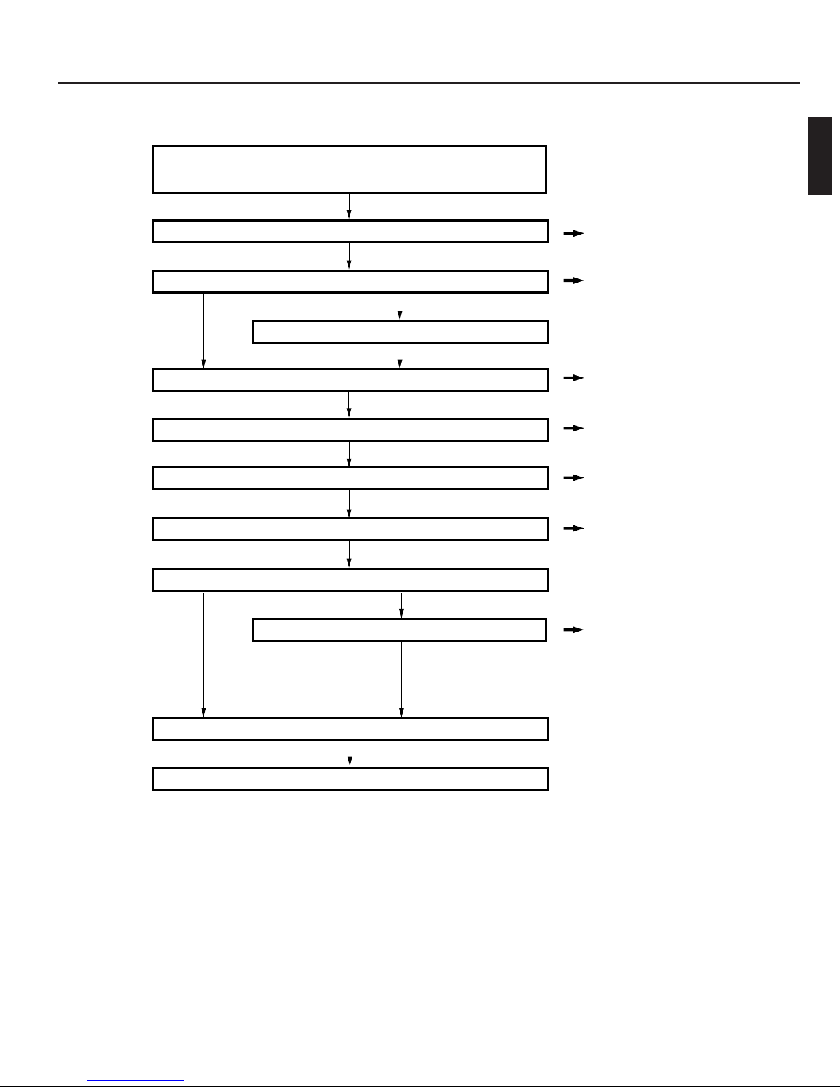
3. SETUP
The standard setup procedure is shown below. Set up the equipment accordingly.
Start
Unpack and check that all the attachments are included.
Open the transport lock
Remove the transport protective materials (2 places.)
Mount the optional carrier *2.
Install the drive units
Initial setup of SCSI-ID No., etc.
Connect the power cord and cables
Execute the automatic drive detection mode.
ENGLISH
P.10
P.11
P.21
P.12
P.13
P.22
Load discs in the magazines *
Turn the power switch on.
Completion
Proceed to the host computer setup
1
A large number of discs can be loaded quickly(bulk load).
*
2
Please have your dealer or nearest JVC service center perform this task.
*
1
P.18, 25
9
Page 14
Setup
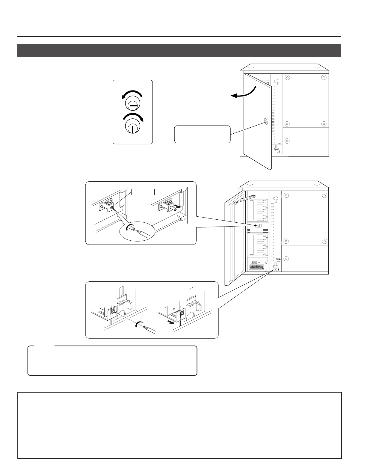
3-1. Opening the transport lock
1.
Open the door by inserting the key and turning it
counterclockwise (90°) to unlock the door.
Unlocked
Locked
2.
Open the transport lock of the mail slot.
• Using a philips screwdriver, continue to turn the lock
counterclockwise until the lock is completely disengaged and moves outwards.
Lock pin
Door opening/closing
key cylinder
3.
Unlock the transport lock of the carrier.
• Continue to turn the screw counterclockwise to loosen
it until the metal device retaining it is disengaged and
moves outwards.
Note:
When using the MC-CF10U Optional Carrier, read "3-3. Removing the optional carrier transport lock screw" on page
12 before continuing on.
Proceed to the operation in the next page without closing the door.
• In the case of re-transporting, lock the transport lock as follows:
1) Remove all the discs and turn off the power.
2) Turn on the power while pressing the “1” of the 10-key pad and enter the PACKING mode.
3) Turn off the power as soon as the “END” display appears on the LCD screen.
2
4) Fix the transport lock as described in
5) When using the MC-CF10U Optional Carrier, read "3-3. Removing the optional carrier transport lock screw" on
page 12 before continuing on.
6) Re-attach the protective transport materials. (a See page 11.)
and 3 above.
10
Page 15

3-2. Removing the transport protective materials
After opening the transport lock, proceed to the following steps without closing the door.
1.
Remove magazine No. 1.
(a See “9-1. Ejecting/loading the magazines” on page 24.)
TOP
2.
Pull out the protective material forwards.
Setup
ENGLISH
2
Protective material
3.
Load magazine No. 1.
(a See “9-1. Ejecting/loading the magazines” on page 24.)
TO
P
4.
Repeat the same operation for magazine No. 2.
• In the case of re-transporting, it is necessary to remove all the discs and re-attach the protective transport materials
using the reverse procedure to the above. When this operation is required, please consult your dealer or nearest JVCauthorized service agent.
• Although the MC-8100U is compatible with the optional MC-AP30U color disc Printer, it should be removed from the
system before transporting it. Otherwise, the printer and its outer panel may get damaged during transport.
11
Page 16

Setup
3-3. Removing the optional carrier transport lock screw
When the MC-CF10U is installed, its special transport lock should be removed in addition to its being unlocked as detailed in "3-
1. Opening the transport lock" on page 10. Use the following procedure when unlocking the optional carrier transport lock.
1.
Remove the transport lock screw
(for optional carrier).
2.
Insert the removed screw into
the designated storage hole for
the transport lock screw.
• If the system is transported with the MC-CF10U Optional Carrier installed, refer to "3-1. Opening the transport lock",
execute the packing mode and clamp the above-mentioned transport lock screw.
3-4. Installing drives and settings SCSI-ID No., etc.
1.
Installing drives
Install the drives ( a See "7. DRIVE UNITS" on page 21).
2.
Initial setting of SCSI-ID No., etc.
The default setting of the SCSI-ID No. of the MC-8100U is "0".
Set the SCSI-ID No. according to your system.
• To change the SCSI-ID No. of the MC-8100Ua Read "8. SETUP OF SCSI ID NUMBER OF THE MAIN UNIT" on
page 23.
• To set the SCSI-ID Nos. and termination of drives a Read the instruction manuals of the installed drives.
• As the MC-8100U should be turned on to allow its SCSI-ID No. to be set, read "3-5. Connecting the power cord and
cables" on page 13 and connect the power cord before proceeding.
• When using an external active terminator, set the termination settings of the installed drives to OFF.
12
Page 17

3-5. Connecting the power cord and cables
CAUTION
Turn OFF the power of all equipment before starting connections.
Connecting the equipment while power is ON may lead to a malfunction.
To SCSI-A
Attach the provided clamp filters.
To AC IN
Setup
ENGLISH
To SCSI port of
host computer
To AC outlet
Always use the power cord provided by JVC. The library system has been designed to conform to
WARNING
“Insulation category Class 1”. In order to assure safety at all times, be sure to ground the system
before use. If other types of power cords other than the specified cord are used, they may overheat and
burn or cause a fire.
Attaching the clamp filters
Tighten until the tabs are
locked completely.
Attach a clamp filter to the end of the cable.
Pull strongly.
Pull hard
Push the clamp filter against the connector
and secure it by using the provided strap.
Cut any
surplus part.
• The allowable length for the SCSI cable inside the equipment is about 1.2 meters. In the case of SCSI-2 10
Mbytes/sec. sync operation, if the total length of the SCSI cabling including those cables outside the equipment
exceeds 3 meters, a malfunction may result. However, if the SCSI-2 5 Mbytes/sec. async mode is used the total
length of the SCSI cabling should be no more than 6 meters.
• Use a shielded SCSI cable with high-impedance specifications and be sure to attach the provided clamp filter to
the cable. Using other type of cable or using a cable without a clamp filter may cause radio wave interference and
a malfunction.
13
Page 18

4.
CONTROL PANEL OPERATIONS AND LCD DISPLAY
The key operation and LCD display system has three main operation and display modes as described below.
Normal display ..... This mode includes two patterns, one of which is displayed automatically when the equipment starts
up normally. The disc numbers in the drive units are displayed in real time.
Menu display ........ This mode allows you to start user operations such as SCSI ID No. checking and setting, internal
history display, access count display, disc loading by the library only, door opening, etc.
Event display ........ This mode overrides other modes in case of an event such as initialization after startup, mail slot
operations, setting up the door/panel opening mode or appearance of errors.
4-1. Normal display
Pattern 1 is displayed automatically when the startup has succeeded normally. The display changes every time the SELECT
key is pressed.
[Pattern 1]
Carrier
Idle Mail slot
CR : – – – MS : – – –
D1 : 0 3 6 D2 : 0 7 5
Drive 1
Disc No.
SELECT
[Pattern 2]
D3 : NC D4 : NC
Drive 3
Drive 4
4-2. Menu display
Pressing the MODE key during normal display starts the menu display.
Select a menu by pressing the SELECT key and enter the selection by pressing the ENTER key.
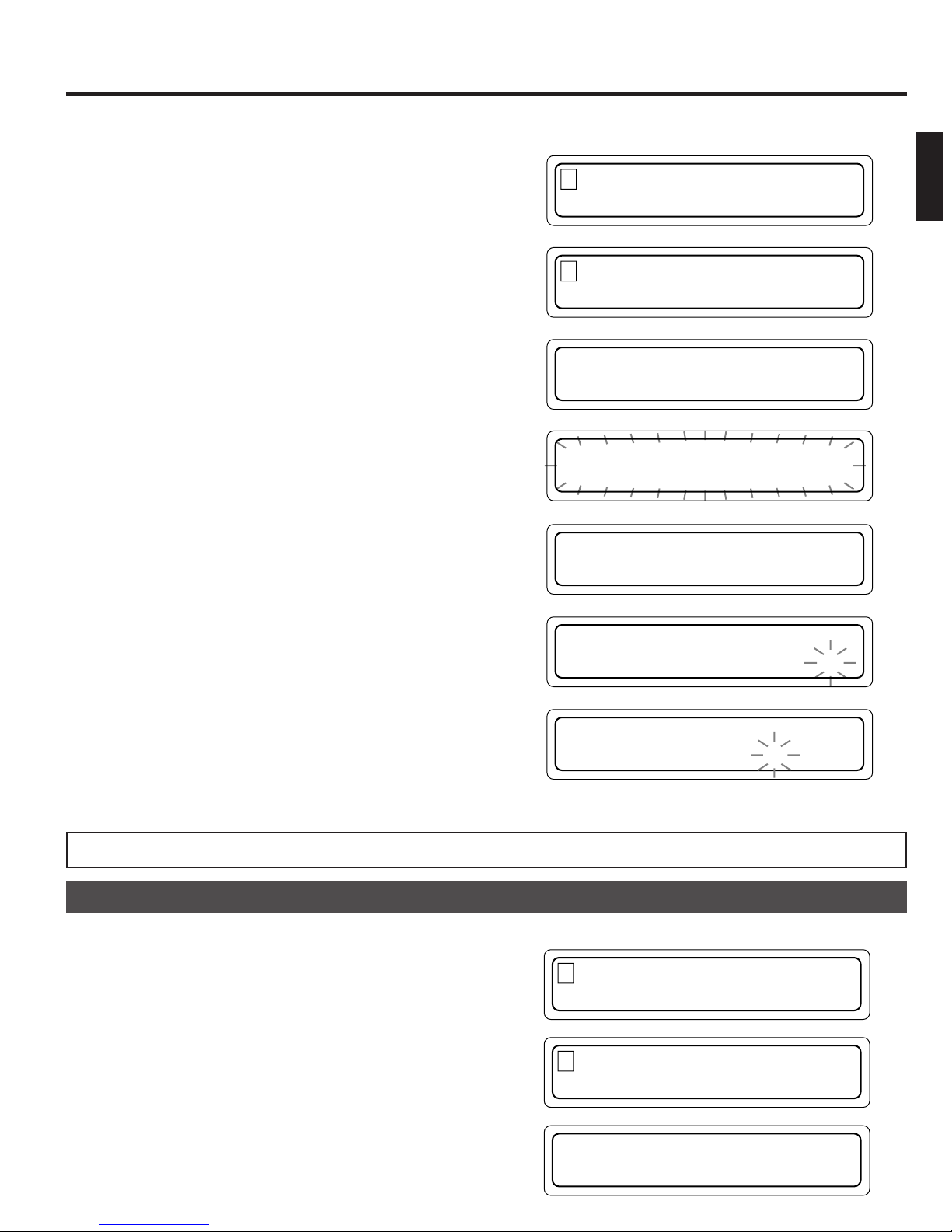
NORMAL DISPLAY
1
(a See "4-1. Normal display" on this page.)
ERROR DISPLAY
2
(a See "10-4. Error history display" on page 29.)
ID No. DISPLAY
3
(a See "8-1. Display for checking the SCSI ID numbers" on page
23.)
PANEL OPEN
4
(a See the instruction manual of the optional MC-AP30U Color
Disc Printer.)
DOOR OPEN MODE
5
(a See "5. Door Opening/Closing" on page 17.)
ID No. SET MODE
6
(a See "8. Setup of SCSI ID number of the main unit" on page
23.)
COUNT DISPLAY
7
(a See "11. Access counts" on page 30.)
IMPORT/EXPORT
8
(a See "6-2. Import/export operation" on page 19.)
DRIVE DISPLAY
9
(a See "7.7. Drive type display" on page 22.)
PRINTER MODE
0
(a Display only when the optional MC-AP30U Color Disc Printer
is installed.)
14
Cursor: Currently selected menu
1 . NORMAL D I SP L AY
2.ERROR DISPLAY
.ERROR DISPLAY
2
3. ID No.DISPLAY
9
.DRIVE DISPLAY
1 . NORMAL DI SPLAY
Drive 2
SELECT
Unconnected
SELECT
SELECT
Page 19
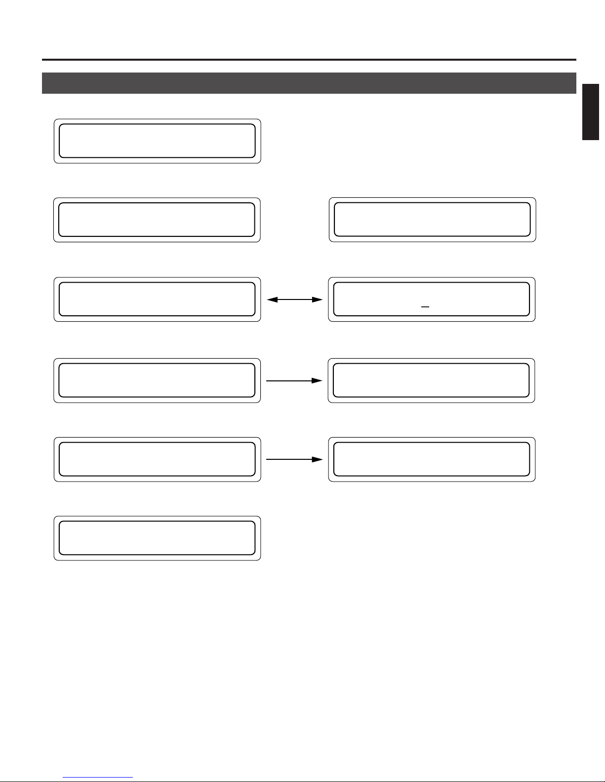
4-3. Event display
Power on
1
POWER ON
Control Panel Operations and LCD Display
ENGLISH
During initialization
2
When the MC-CF10U Optional Carrier is installed
INITIALIZING
Error occurrence (a See “10-2. Error code list” on page 28.)
3
Displayed
E
RROR OCCURRED !
During door opening (a See “5. Door Opening/Closing” on page 17.)
4
alternately.
E X ECUT I NG DOOR
OPEN PROCESS
When door is open (a See “5. Door Opening/Closing” on page 17.)
5
D OOR OR PAN E L
Door closing
IS OPEN
INITIALIZING
FL I P CARR I ER
D ISC=024
CODE =CU
04
THE DOOR
CAN BE OPENED
P USH ENTER KEY
TO RESUME
During mail slot operation (a See “6. Mail Slot” on page 18.)
6
E XPORT DONE
PUSH LOAD KEY
15
Page 20
Control Panel Operations and LCD Display
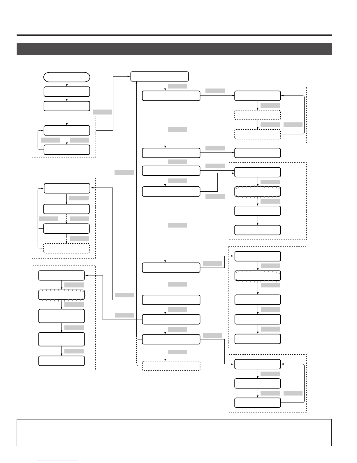
4-4. Display and operation sequence
The sequence of display and operation after turning the power on is as shown below.
Power On
POWER ON
INITIALIZING
Normal display
Pattern 1
SELECT SELECT
Pattern 2
1. TOTAL
2. CR
SELECT
7. DR4
1
*
8. FL
PUSH SEL. KEY
PUSH SEL. KEY
Input the start
tray No.
Input the end
tray No.
Start accessing
SELECT
SELECT
SELECT
SELECT
SELECT
ENTER
ENTER
MODE
SELECT
ENTER
ENTER
1. NORMAL DISPLAY
SELECT
2. ERROR DISPLAY
SELECT
3. ID No. DISPLAY
SELECT
4. PANEL OPEN MODE
SELECT
5. DOOR OPEN MODE
SELECT
6. ID No. SET MODE
SELECT
7. COUNT DISPLAY
SELECT
8. IMPORT/EXPORT
SELECT
9. DRIVE DISPLAY
SELECT
2
*
10. PRINTER MODE
*1. When the MC-CF10U Optional
Carrier is installed.
*2. When the optional MC-AP30U
Color Disc Printer is installed.
ENTER
ENTER
ENTER
ENTER
ENTER
ENTER
Error display 1
SELECT
Error display 2
SELECT SELECT
Error display 8
SCSI-ID display
PUSH SELECT
SELECT
PUSH SELECT
SELECT
EXECUTING ...
... CAN BE OPENED
PUSH SELECT
SELECT
PUSH SELECT
SELECT
ID No. display
SELECT
Input ID No.
ENTER
ID No. entry
DR1 :
SELECT
DR2 :
SELECT SELECT
• If the MODE, SELECT or ENTER key has not been pressed within 10 seconds, the current display will return to “Normal
display - Pattern 1” (except in a situation when an event is displayed or the Import/Export Tray numbers and SCSI-ID
numbers are being input).
16
DR4 :
Page 21

5. DOOR OPENING/CLOSING
The door is closed.
The door is open.
P USH ENTER KEY
TO RESUME
D
OOR OR PANEL
I S OPENED
Once the transport locks have been opened and the power has been turned on for the first time (the optional MC-AP30U label
printer may also have been incorporated), the door is locked by the internal safety locking system in addition to locking by the
door opening/closing key, so that the door cannot be opened by the key alone.
To open the door under these conditions, keep the power on, or turn it on if it had been off, and then perform the following
operations before using the door opening/closing key.
ENGLISH
Door Opening
1.
In the normal display mode, press the MODE key.
(The menu display appears.)
2.
Press the SELECT key 4 times.
("5. DOOR OPEN MODE" appears.)
3.
Press the ENTER key.
(Select "5. DOOR OPEN MODE".)
4.
Press and hold the SELECT key for more than 5 seconds.
(Wait until the display starts to blink.)
5.
Release the SELECT key when the execution display
appears.
*When installing/removing drive units, turn off the power
after the completion display (THE DOOR CAN BE
OPENED) appears.
6.
Insert the door key in the cylinder and turn it
counterclockwise to release the lock and open the door.
1 . NORMAL D I SP L AY
2.ERROR DISPLAY
5
.DOOR OPEN MODE
6 . I D No . SET MODE
P
USH SELECT KEY
TO OPEN THE DOOR
P
USH SELECT KEY
TO OPEN THE DOOR
E
XECUT I NG DOOR
OPEN PROCESS
T
HE DOOR
CAN BE OPENED
Unlocked
Door opening/closing
key cylinder
Locked
Door Closing
1.
Close the door and lock it by turning the door key clockwise.
2.
Press the ENTER key when the display on the right
appears.
• The normal display returns after initialization.
• You cannot perform disc transport operations when the above door opening mode is being executed or the door is open.
17
Page 22
6. MAIL SLOT
Label surface
(With a single-sided disc)
6-1. Disc loading
CAUTION
Do not load or eject a disc before the mail slot has stopped completely.
It may not only damage the disc but also cause the equipment to malfunction because of excessive force being applied
during opening and closing.
Disc loading/ejection method
When a tray is transported to the mail slot under the control of
the host computer or the import/export operation
(a see page 19), the mail slot opens automatically when the
transportation has been completed.
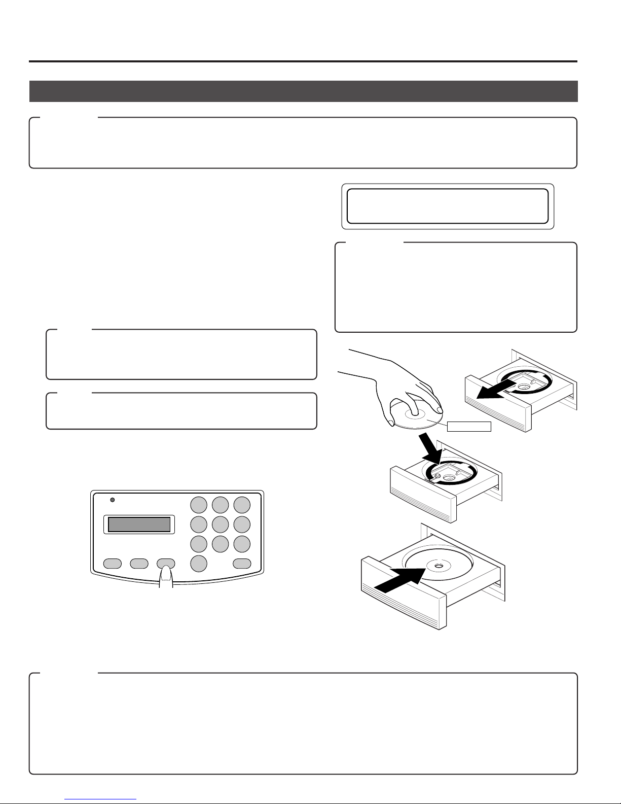
1.
Place a disc gently on the tray with a label surface facing upwards.
(To remove a disc from the tray, hold the disc by the center
hole and the outer edge which is accessible near the notched
section on the front side of the tray.)
Note:
Media compatible with the MC-8100U varies depending on
the installed drive type. For details, refer to the instruction
manuals of the drives.
E XPORT DONE
PUSH LOAD KEY
CAUTION
• A disc may become impossible to write/read due
to dust, fingerprints, scratches, etc. adhering to the
disc surface. Please handle it carefully.
Take special care in handling the DVD-RAM discs
because they are extremely vulnerable to scratches
and contamination.
Note:
When using double-sided discs, handle them with special
care because they do not have a label on the surface.
2.
Press the LOAD/EJECT key.
(The mail slot closes.)
POWER
MODE SELECT LOAD/EJECT
1 2 3
4 5 6
7 8 9
0
ENTER
• Now you can repeat the open/close operations alternately
by pressing the LOAD/EJECT key provided that the mail slot
transportation operation has not started yet.
• While the carrier is in operation, pressing the LOAD/EJECT
key will not start the open/close operations.
CAUTION
• Never use a damaged and/or warped disc or a disc with an attached label. It will lead to a malfunction of the equipment.
• If you are going to use a disc from a different drive, please check the drive specifications carefully before using it.
(Some drives may not be able to read the disc.)
(At the same time, the equipment may not be able to read the disc which has been written and deleted in a different drive.)
• Note that some double-sided discs do not provide a distinction between the top and bottom sides. Take special care
when removing/loading these discs from/in the MC-8100U.
18
Page 23

6-2. Import/export operation
1 .NORMAL DISPLAY
2 . ERROR D I SPLAY
8
. I MPORT / EXPORT
9.DRIVE D ISPLAY
P
USH SEL . KEY FOR
IMPORT/EXPORT
I
NPUT START
TRAY No . : –––
I
NPUT START
TRAY N0o. : 15
I
NPUT END
TRAY No . : –––
I
NPUT END
TRAY N 0o. : 24
IMP ORT / EXPORT
TRAY No . : 015
P
USH SEL . KEY FOR
IMPORT/EXPORT
Mail Slot
When loading/ejecting discs from any chosen tray by the mail slot without the control of the host computer, follow the procedure shown below.
• During the import/export operation, the host computer commands which include the carrier operations cannnot be executed.
1.
In the normal display mode, press the MODE key.
(The menu display appears.)
2.
Press the SELECT key 7 times.
("8. IMPORT/EXPORT" appears.)
3.
Press the ENTER key.
(Select "8. IMPORT/EXPORT".)
4.
Press and hold the SELECT key for more than 5 seconds.
(Wait until the display starts to blink.)
ENGLISH
5.
Release the SELECT key when the input start tray
message is prompted.
6.
Enter the start tray number(001-100) using the 10-key
pad.
•If the number is wrong, input a new 3-digit tray No.(ex.
001) again.
7.
Press the ENTER key.
8.
Enter the end tray number(001-100) using the 10-key
pad.
•If you wish to use the import/export operation for single disc, either enter the same end tray number as the
start tray number or press the ENTER key without
entering any number.
9.
Press the ENTER key.
•You can cancel the following operations by pressing
and holding the ENTER key for 5 seconds during the
import/export operation. If the mail slot opens after
cancelling the operation, press the LOAD/EJECT
key.(The tray in operation will be returned to the magazine; then the import/export operation will be completed.)
19
Page 24

Mail Slot
10.
When the mail slot automatically opens, place the desired disc on the tray (number is displayed on the LCD).
(a See "6-1. Disc loading" on page 18.)
•To remove a disc, lift it out of the tray.
•When the following message appears on the LCD display, it is possible that the transport lock of the mail slot has not
been properly released. Please make sure that that lock pin has been removed completely. (a See "3-1. Opening the
transport lock" on page 10.)
CHECK THE LOCK
PIN!
Press the MODE key to return to the menu display.
11.
Press the LOAD/EJECT key. (The mail slot closes and the tray is returned to the magazine.)
12.
When continuous import/export operations are required, repeat steps 10 and 11.
(The tray number on the LCD display count will increment by one.)
•If the tray cannot be found in the magazine (including instances when the tray is in a drive or the color disc printer), this
tray No. will automatically show up on the LCD display and then the import/export operation will be completed.
NO T RAY
TRAY No. : 015
Press the MODE key to return to the menu display.
In the following instances, the import/export operation cannot be performed and the LCD display will indicate as shown
on the right.
Clear the following conditions on the host computer side first and
then input again.
• When a tray is in the mail slot.
• When the carrier operation is being executed.
• When the host computer control is prohibiting import/export
operations.
• If the disc positioning in the main unit (the changer) has been altered or the contents of a disc have changed bacause
of import/export operations, the disc positioning data on the host computer should, as a rule, be renewed.
(hardware and software must stay in sync to ensure proper system operation.)
IMPORT / EXPORT
I S PROH I B I T ED
20
Page 25

7. DRIVE UNITS
CAUTION
• Make sure that the power is turned off when installing/removing, connecting or setting any drive.
Performing these operations while the power is on will result in the equipment malfunctioning.
Be sure to read the instruction manuals of the drive units before proceeding to any of the following work.
• Note that certain device drivers are incompatible with the simultaneous use of more than one type of drive (mixed use).
Please consult your dealer or nearest JVC service center.
7-1. Removing the panels
1.
Open the door.
(a See "5. Door opening/closing" on page 17.)
Rear panel
2.
Turn off the power.
3.
Remove the rear panel.
• Remove the 6 screws.
• Carefully disconnect the SCSI cable from the drive.
(a See "7-4. Connecting the cables" on page 22.)
ENGLISH
4.
Remove the side panel.
• Remove the 4 screws.
Side panel
7-2. Installing the drive units
• When removing the drive units, be sure to disconnect the control cable and power cable beforehand.
(a See "7-4. Connecting the cables" on page 22.)
1.
Inserting a drive unit.
• Always insert it into a bay with the lowest available
bay No.(from bottom to top)
• Be careful not to snag any cables.
• Be careful not to damage the sensor slit.
2.
Secure the drive unit using the provided metric screws.
• The provided metric screws are attached to the optional drive unit.
* Be careful not
to damage the
sensor slit.
Sensor slit
CAUTION
Be sure to attach the screws securely. If the library system is operated without the screws, either the library or
the drives may be damaged.
21
Page 26
Drive Units
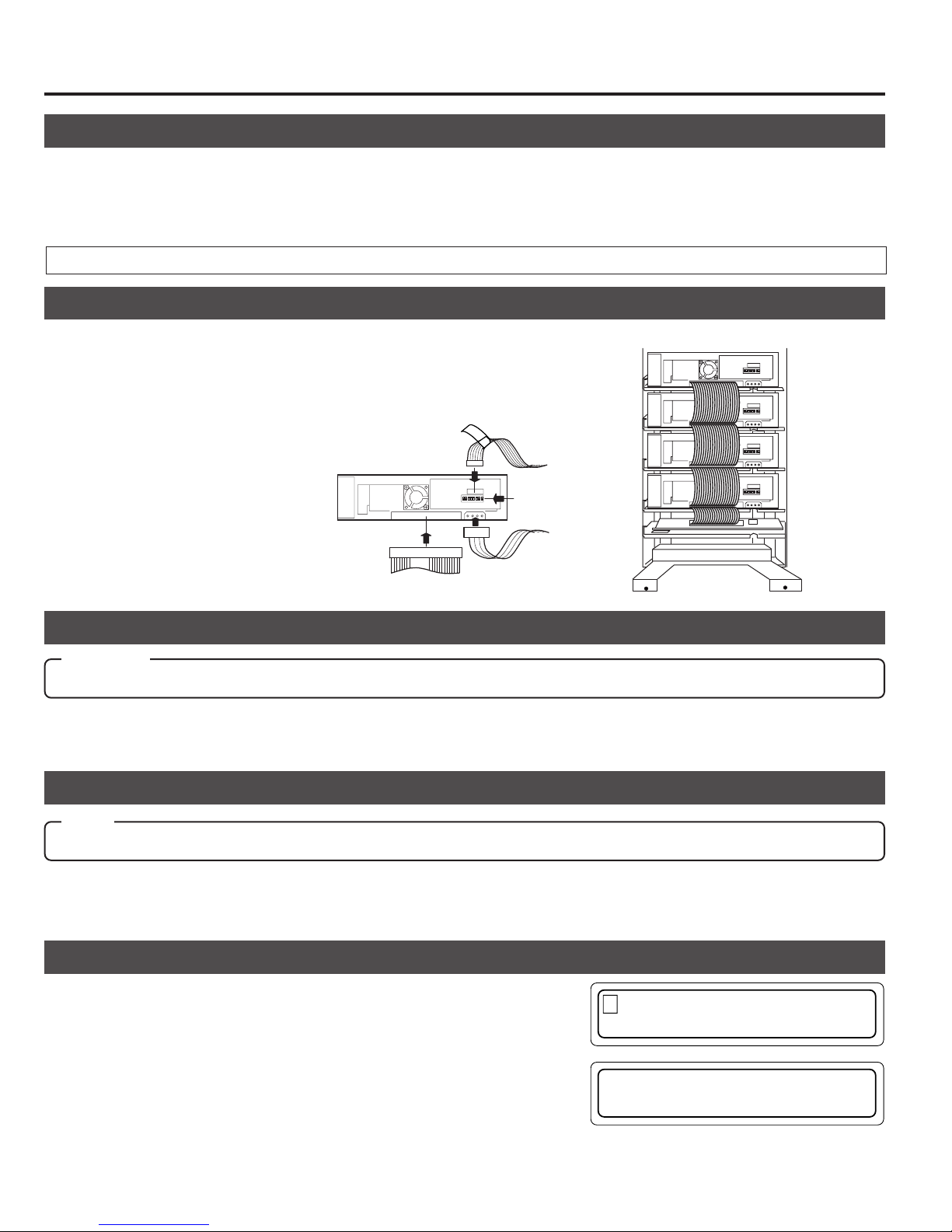
Internal SCSI cable(approx. 1.2 m)
Changer SCSI
board
Drive No. 4
4
Drive No. 3
3
Drive No. 2
2
Drive No. 1
1
9 .DRIVE DISPLAY
1 .NORMAL D I SPLAY
D R1 : DVD– RAM
DR2 : ROM / e t cR
7-3. Setting the SCSI ID numbers, etc.
s Procedure for the setting the SCSI ID Nos. and other jumpers, please refer to the specified section(s) of the corresponding
drive instruction manuals.
s Make sure to turn the power OFF before starting with the setting procedure. If the procedure is carried out with the power
ON, it will cause malfunction.
s The new ID Nos. will become effective from the moment the power is turned on.
s The new SCSI ID Nos. should not conflict with the ID Nos. of other SCSI equipment on the same SCSI bus.
7-4. Connecting the cables
Please refer to a relevant section of an optional drive unit's instruction manual for
the correct connector positions of the cables.
1.
Connect the control cable (14P).
• Connect the cable with the corresponding number to the drive bay No. If the
cable with the wrong number is connected, it will lead to the equipment malfunctioning.
2.
Connect the power cable (4P).(The figure shows the case with the MC-R200U.)
3.
Connect the SCSI cable
3
SCSI cable
1
1
2
Control cable
14p
Drive jumber settings
4p
Power cable
7-5. Installing the panels
CAUTION
Check the installation screws and cables before installing the panel. Insufficient connections may cause malfunctions.
s
1.
Attach rear and side panels.
• Screw the panels on, following the procedure in "7-1
Removing the panel" on page 21 in the reverse order.
7-6. Automatic drive detection mode
Note:
After installing, adding, exchanging or removing drives, be sure to execute the auto drive detection mode to prevent any malfunction.
1.
While holding key "8" on the control panel, turn on the
MC-8100U.
7-7. Drive type display
The types of the installed drives can be confirmed by the display.
1.
Press the MODE key while the LCD display is in normal display mode
(to display Menu display).
2.
Press the SELECT key 8 times (to display "9. DRIVE DISPLAY").
3.
Press the ENTER key (to select "9. DRIVE DISPLAY").
4.
The type of the drive in each drive bay will be displayed. (Each press of
the SELECT key displays the information on the next drive.)
Meaning of the display
"DVD-RAM" : DVD-RAM drive "ROM/R etc" :Non DVD-RAM drive (CD-ROM/R, DVD-ROM, etc.)
"NO DRIVE" : Drive is not connected or installed "UNKNOWN" : When drive detection mode has not been executed.
● If the automatic drive detection mode has not been executed, the LCD displays “UNKNOWN DRIVE DETECTED”.
22
2.
Close the door
(a See "5. Door Opening/Closing" on page 17.)
2.
When the LCD display shows "DRIVE DETECTION
COMPLETED", turn off the power of the MC-8100U.
3.
Turn the MC-8100U on again.
Page 27
8. SETUP OF SCSI ID NUMBER OF THE MAIN UNIT
The SCSI ID No. set for the main unit (changer) can be modified as described below.
1.
In the normal display mode, press the MODE key.
(The menu display appears.)
2.
Press the SELECT key 5 times.
("6. ID No. SET MODE” appears.)
3.
Press the ENTER key.
(Select “6. ID No. SET MODE".)
4.
Press and hold the SELECT key for more than 5 seconds.
(Wait until the display starts to blink.)
1 . NORMAL D I SPL A Y
2 . ERROR D I SPLAY
.IDNo.SETMODE
6
7 . COUNT D I SP L AY
USH SELECT KEY
P
TO CHANGE I D No .
P
USH SELECT KEY
TO CHANGE I D No .
ENGLISH
5.
Release the SELECT key when the current ID No. ap-
C
pears.
HANGER
SCS I I D No . =0
6.
Select a new ID No. using the keys 0 to 7.
HANGER
7.
Press the ENTER key. (The ID No. being displayed is
entered.)
• The set ID No. becomes effective from the next time
power is turned on.
C
SCS I I D No .=3.
C HANGER I D No .
IS SET TO 3
• The new SCSI ID No. should not conflict with the ID Nos. of other SCSI devices existing on the same SCSI bus.
8-1. Display for checking the SCSI ID numbers
The SCSI ID Nos. set for the main unit (changer) and installed drive units can be checked as described below.
1.
In the normal display mode, press the MODE key.
(The menu display appears.)
1 . NORMAL D I SPL A Y
2 . ERROR D I SPL AY
2.
Press the SELECT key twice.
("3. ID No. DISPLAY” appears.)
3.
Press the ENTER key.
(Select “3. ID No. DISPLAY".)
The following information is displayed.
CH: Changer
DR1 to 4: Drives 1 to 4 ("-” indicates “Not Connected".)
. ID No . D I SPLAY
3
4 . PANEL OPEN MODE
C
HDR1234
012––
23
Page 28

9. MAGAZINES
CAUTION
• Do not use a magazine which has been damaged (e.g. dropped), as normal operation cannot be accomplished with
such a magazine. In addition, the use of such a magazine may damage the internal mechanism.
• The magazines and trays used with the MC-1000/2000 series CD-ROM Library (MC-M15U) are not compatible with those
used with the MC-8000 series CD/DVD Library. Do not interchange the magazines and trays between these models, as this
will damage the equipment.
• If it is required to take out or attach a magazine during operation, be sure to perform optimum software processing at the host
in advance.
9-1. Ejecting/loading the magazines
Ejection
1.
Open the door. (a See “5. Door Opening/Closing” on page 17.)
*
Do not turn off the power switch.
2.
Pull the release lever toward the front.
• The magazine unlocks and comes out slightly toward the
front. Be careful not to get your finger caught between
the release lever and grip.
3.
Pull the magazine straight toward the front.
• Use care not to hit or drop the magazine.
• Be careful not to touch the tray lock by mistake.
A tray may spring out.
Release lever
2
3
Grip
Loading
1.
Check the orientation of the magazine.
• The [c TOP] marking is provided on the grip to indicate the
upper direction of the magazine.
2.
Align the magazine rails with the guide on the main unit
(changer) and insert it straight forward.
•
Insert the magazine slowly. Inserting it with a strong force
may damage the equipment.
•
Ensure that the magazine guides are fitted in the guides
located at the left side of the library (both at the top and
bottom of the sides).
3.
Push in the magazine completely until it stops.
•
Then, pull the magazines slightly toward the front to ensure that it is locked.
4.
Close the door (See "5. Door Opening/Closing" on page 17.)
* If a magazine was removed and installed and the door closed
after the power has been turned on, this function will automatically check the disc status inside the magazine.(provided that
the automatic disc checking function has been turned ON AP.26).
TOP
Tray lock
The magazine guides are fitted
in the guides located at the left
side of the library
TOP
Display in case of incomplete insertion
The front panel display will indicate an error if the door is closed while the magazine insertion is incomplete. Check the
incorrectly inserted magazines from the displayed message and re-insert them completely until they are locked.
E RROR OCCURRED !
DISC=–––
CODE = CC– 31
24
RORMAGAZINE
E
R
No . : – 2
Display when the insertion of magazine
No. 2 is unsatisfactory
Page 29
Magazines
9-2. Loading/replacing the discs
CAUTION
• When loading discs directly into the magazine trays without using the mail slot, be careful not to damage the magazines
and trays.
• A disc may become impossible to write/read due to dust, fingerprints, scratches, etc. adhering to the disc surface. Please
handle it carefully.
• Take special care in handling the DVD-RAM discs because they are extremely vulnerable to scratches and contamination.
ENGLISH
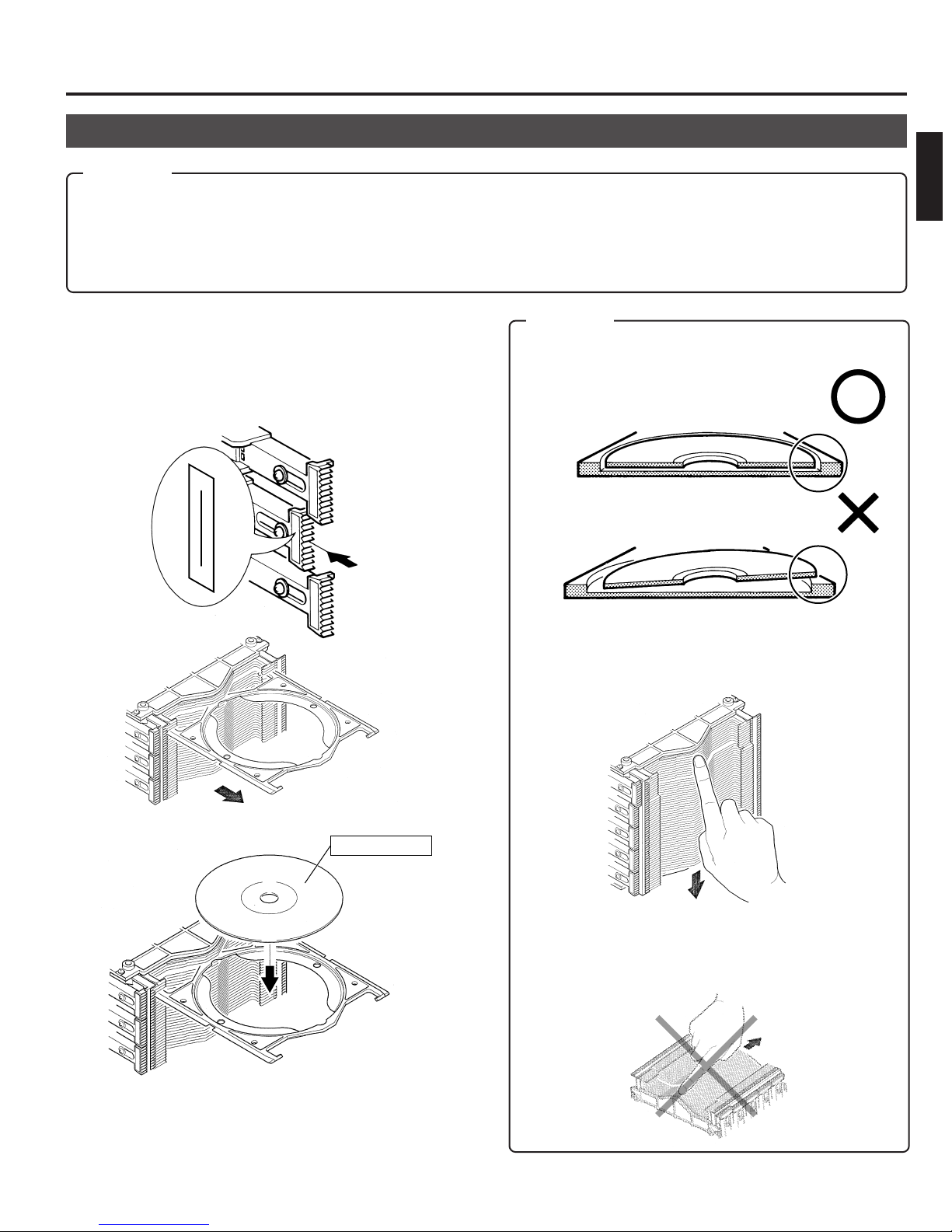
1.
Eject a magazine. (a See “9-1. Ejecting/loading the
magazines” on page 24.)
2.
Unlock the tray lock corresponding to the tray to be used.
(a See “2-3. Magazine numbers, tray numbers, disc
numbers” on page 8.)
30
21
3.
Pull out the tray.
CAUTION
(1) Place the disc correctly on the disc tray so that it does
stay in the guide section of the disc tray.
(2) To prevent projection of a tray or incomplete locking
of the tray lock, align the edges of all the trays in the
magazine by slightly pushing them inward from.
4.
Place the disc on the tray.
5.
Push in the tray and lock the tray lock.
6.
Load the magazine in the changer. (a See “9-1. Ejecting/loading the magazines” on page 24.)
Label surface
(With a single-sided disc)
(3) Always handle the magazine the correct way.
Holding or placing a magazine upside down or on its
side may cause the discs to slip out of position and
result in malfunction.
25
Page 30

Magazines
Note:
• Media compatible with the MC-8100U varies depending on the drive configuration. For details, refer to the instruction
manuals of the drives.
• When using double-sided discs, handle them with special care because they do not have a label on the surface.
CAUTION
• Never use a damaged and/or warped disc. It will lead to malfunction of the equipment.
• If you are going to use a disc from the different drive, please check the drive specifications carefully before using it.
(Some drives may not be able to read the disc.)
(At the same time, the equipment may not be able to read the disc which has been written and deleted in a different
drive.)
• Note that some double-sided discs do not provide a distinction between the top and bottom sides. Take special care
when removing/loading these discs from/in the MC-8100U.
9-3. Automatic disc checking function
If a magazine was removed and reinstalled after the power has been turned on, this function will automatically check the disc
status inside the magazine.
Checking the operation modes.
Press and hold the MODE key for more than 5 seconds.
• The factory default setting for the automatic disc checking function is on.
Automatic disc checking function ON
A UTO DISC CHECK:
ON
Switching the operation modes
Operation modes will alternate (toggle) when you turn the power off, and then on while pressing both the SELECT key and
the LOAD/EJECT keys simultaneously.
sDepending on the management software used, you may still have to update the disc status data of the host computer
even after the automatic disc checking function has updated the disc status data of a magazine.
Automatic disc checking function OFF
A UTO DISC CHECK:
OFF
26
Page 31

10. ERROR CODES
In the event of an error, the control panel indicator blinks and the LCD shows the error details by overriding any other
information.
The indicator blinks.
POWER
MODE SELECT LOAD/EJECT
10-1. Error code explanation
LCD displays in the event of an error
ERROR OCCURRED !
If the transport lock of the carrier
has not been opened,
this section shows “CHECK
CAR. SCREW”.
DISC = 024
CODE = CU–04
E R OR MAGA Z I NE
R
No. : – 2
Display when
CODE = CC-31
1 2 3
4 5 6
7 8 9
0
ENTER
DISC = 024
Disc No.
CODE = CU – 04
Error code
Unit detail code
Unit in error
Disc No. : Shows the disc No. being accessed at the moment of error
occurrence. "---" is displayed if no disc is accessed at the moment
of error occurrence.
ENGLISH
Units in error and unit detail codes
Unit in error Unit detail code
C Carrier
M Mail slot
D1 to D4 Drive
P Color Disc Printer
• When an error occurs, write down the error code before turning the power off, except in the case of an urgent problem
such as smoke.
U Up/down
L Tray lock
C Catcher
D Disc
F Flip
E Ejection
L Loading
T Tray
T Tray
C Clamp
E Ejection
D Disc
S Spindle
T Tray
27
Page 32

Error Code
10-2. Error code list
Device
(D#)
*1: # represents the drive number.
*2: Check the magazine loading condition. (
Device
part
C U 04 UP/DOWN motor does not function
C L 11 Tray lock impossible, or lane change not possible
C C 26 Right catcher sensor does not turn on
C
M L 51 Mail Slot loading is not possible
P T 72 Destination-unknown tray exists in the Label Printer
D 42 No disc in the tray
F
E 50 Mail Slot ejecting is not possible
T 52 Destination-unknown tray exists in the Mail Slot
T
C 62 Disc clamp of the drive does not function
E 63 Drive ejection is not possible
*1
D 64 Failure to remove the disc from the drive
S 65 Spindle motor fails to stop
Error
code
01 UP/DOWN rotary sensor does not change
02 Left slit sensor does not change
03 Right slit sensor does not change
05 UP/DOWN motor doesn’t work correctly or rotary sensor defective
08 UP/DOWN operation exceeds the predetermined duration
09 Upper or lower limit sensor turn on during UP/DOWN operation
10 Tray lock release not possible
12 Tray lock does not exist at the initial position during carrier movement
20 Catcher (right
21 Catcher (left
22 Catcher (right
23 Catcher (left
24 Catcher (right
25 Catcher (left
27 Left catcher sensor does not turn on
28 Catcher motor (right
29 Catcher motor (left
30 Tray does not exist
*2
31 Magazine insertion incomplete, or sensor defective
41 Destination-unknown tray exists on the carrier
43 Flip tray does not exist
80 During the flip raise operation, the expected time required is over
81 During the flip descent operation, the expected time required is over
60 Destination-unknown tray exists in the Drive and the control cable of the Drive is disconnected.
61 Tray removal is not possible at the drive position
left) movement operation exceeds the predetermined duration
a
right) movement operation exceeds the predetermined duration
a
left) convergence operation exceeds the predetermined duration
a
right) convergence operation exceeds the predetermined duration
a
left) tray rotary sensor does not change
a
right) tray rotary sensor does not change
a
left) does not function
a
right) does not function
a
See “9-1. Ejecting/loading the magazines” on page 24.)
a
Description
10-3. How to cancel the Error "64"
Please have your dealer or local JVC-authorized service agent perform this work.
Error “64” occurs when the removal of a disc from a drive fails or when the position of a disc on the tray is unstable.
During the occurrence of Error "64", even if the power is turned ON again, the unit will not startup. Perform the following operation:
1.
Open the door and remove the side and center panels.
2.
Remove both the disc and the tray from the drive and
that is on the carrier. Contact JVC for assistance.
28
3.
Close the door, then while pressing the '0' key, turn the
power ON.
* If the cancellation of the Error "64" is performed without
removing the disc and tray from the carrier, damage to
either or both of them may result.
Page 33

10-4. Error history display
The history of past errors can be displayed as described below.
1.
In the normal display mode, press the MODE key.
(The menu display appears.)
2.
Press the SELECT key once.
("2. ERROR DISPLAY” appears.)
3.
Press the ENTER key.
(Select “2. ERROR DISPLAY".)
"NO ERROR FOUND” appears if no error has occurred
in the past.
If there is any past error, the data on the latest 8 error
occurrences can be recalled from memory and displayed.
4.
Press the SELECT key to display the data on past errors in sequence.
Error history
The smaller the number,
the more recent the error
occurred.
Error codeDisc No.
1 . NORMAL DISPLAY
2 . ERROR DISPLAY
2 . ERROR DISPLAY
3 . ID No. DISPLAY
ER1 : 007 – CU08
–CC20 – CL10 – CU02
Error Code
ENGLISH
When there is
no error history
NO ERROR FOUND
* If a certain error has a history
of successive occurrences, the
second and later errors are
shown in the second line. The
data is displayed in a single line
when there are no successive
errors.
ER1 : 007CU08
ER8 : 025 – CC24
CC20CL10CU02
Error codes
● This data may be lost if the equipment is disconnected from the power source for more than six months.
10-5. Troubleshooting
When the following conditions occur, check items listed on the right.
Conditions Causes
The drive unit SCSI ID No. is conflicting. (a P. 8 )
The end of the SCSI line is not terminated. (a P. 8 )
The SCSI cable is either too long or not sealed sufficiently.(a P. 13)
The changer or drives cannot be recognized by the host computer.
The drive is identified but a disc cannot be transported to the drive.
Read (write) errors occur.
The initial setup of the SCSI device is not possible using a driver software.
The LCD display shows "UNKNOWN DRIVE TYPE DETECTED".
The host computer SCSI board is not set to SCSI-2.(a P. 13)
The drive unit SCSI connector is improperly connected. (a P. 22)
The drive unit power cable is improperly connected. (a P. 22)
Overlapping of the SCSI-ID Nos. has occurred. (
The drive unit control cable is improperly connected. (
The disc is either dirty or damaged. (a P. 5 )
The drive unit SCSI ID No. is conflicting. (a P. 8)
The end of the SCSI line is not terminated. (a P. 8 )
The SCSI cable is either too long or not sealed sufficiently.(a P. 13)
The host computer SCSI board is not set to SCSI-2.(a P. 13)
The drive unit control cable is improperly connected. (
a
SCSI ID Nos. are conflicting. (
The drive detection mode has not been executed. (a
P. 13, 22)
a
P. 22)
a
a
P. 13, 22)
P. 22)
P. 22)
29
Page 34

11. ACCESS COUNTS
Access counts of the main unit (changer) and each unit (carrier, drives 1 - 4 and label printer) can be checked using this
function.
1.
In the normal display mode, press the MODE switch.
(The menu display appears.)
2.
Press the SELECT key 6 times.
("7. COUNT DISPLAY" appears.)
3.
Press the ENTER key.
(Select "7. COUNT DISPLAY".)
4.
Pressing the SELECT key changes the display.
1. TOTAL : The total access count for the Library.
2. CR : Carrier
3. MS : Mail slot
4. DR1 : Drive 1
5. DR2 : Drive 2
6. DR3 : Drive 3
7. DR4 : Drive 4
8. FL : Flip
Only when the MC-CF10U Optional Carrier is installed
9. PR : Printer
Only when the MC-AP30U Label Printer is installed.
However, if an optional carrier is installed “8. PR” will be
displayed.
1 .NORMAL DISPLAY
2 . ERROR D I SPLAY
. COUNT D I SP L AY
7
8 . I MPORT / EXPORT
.TOTAL:000237
1
2 . CR : 0 00179
.CR
2
3. MS
: 000179
: 000020
SELECT
7
. DR4 : 000004
1.TOTAL:000237
SELECT
.TOTAL:000237
1
2. CR :000179
s Access counts of unconnected drive units will appear as[------].
s The initial "TOTAL" access count from the factory may be "999880-999999".
s This data may be lost if the equipment is disconnected from the power source for more than six months.
SELECT
30
Page 35

SPECIFICATIONS
Item
Number of stored discs
Number of magazines
Operating environment
Rated power voltage
Rated power frequency
Rated current
Power Consumption
Interface
Drive slots rack bays
Media size
Applicable options
Drives
Carrier
Magazine
Printer
Weight
Dimensions
(Unit: mm)
MC-8100U
100
2
Temperature: 5°C-35°C (41°F-95°F) Humidity: 10%-80% (no condensation)
AC120 V - 240 V
50 Hz / 60 Hz
1.4 A - 0.8 A (max. value), 1.1 A - 0.6 A (4 Drives are loaded)
105 W (Reference value, 4 DVD-RAM drives are loaded)
SCSI-2 (Amphenol 50-pin full size)
4
12 cm discs
Availabel drives
DVD-RAM drive
DVD-ROM drive
CD-ROM drive MC-D32U
CD-R drive MC-R18U
For the specifications of the drives, refer to their relevant instruction manuals.
For other drives, consult your dealer or nearest JVC service center.
Double-sided disc compatible carrier: MC-CF10U
Magazine set: MC-M25U (B)
Compatible with color disc printer (MC-AP30U)
42 kg (Excluding the discs and optional equipment)
MC-R400U
MC-R200U
MC-D104U
MC-D18U
MC-R14U
MC-R12U
Rec/Play
Play DVD-ROM, CD-ROM/R, etc.
Rec/Play DVD-RAM with 2.6 GBytes/side
Play DVD-ROM, CD-ROM/R, etc.
Play DVD-ROM, CD-ROM/R, etc.
Play CD-ROM/R, etc.
Rec/Play CD-R, CD-RW (Records with MC-R18U only)
Play CD-ROM/R, etc.
View when the door is open (Top view)
DVD-RAM with 4.7 GBytes/side and 2.6 GBytes/side
Compatible discs
ENGLISH
340
616
277
680
Design and specifications are subject to change without notice.
31
Page 36

MC-8100U CD/DVD LIBRARY
is a registered Trademark owned by VICTOR COMPANY OF JAPAN, LTD.
is a registered Trademark in Japan, the U.S.A., the U.K. and many other countries.
© 2000 VICTOR COMPANY OF JAPAN, LIMITED
VICTOR COMPANY OF JAPAN, LIMITED
Printed in Japan
SS961554-002
Page 37

SECTION 1
CIRCUIT BOARD COMPATIBILITY
MC-8100U
Model
Unit Name
SCSI PCB ASS'Y MC81-SCSI MC82-SCSI MC71-SCSI MC72-SCSI MC21-SCSI MC22-SCSI MC12-SCSI
CHASSIS PCB ASS'Y MC81-CHAS MC82-CHAS MC71-CHAS MC72-CHAS MC21-CHAS MC22-CHAS MC12-CHAS
CARRIER MECHA ASS'Y
MAIL SLOT ASS'Y MC12-MAIL
U/D MOTOR ASS'Y MC21-UD-M MC12-UD-M MC21-UD-M MC12-UD-M MC21-UD-M MC12-UD-M MC12-UD-M
MAGAZINE SET MC-M25 (B) MC-M25 MC-M15
POWER UNIT ASS'Y QAL0141-001 QAL0112-001 QAL0141-001 QAL0112-001 QAL0141-001 QAL0112-001 MC12-POWR
CD-ROM DRIVE MC-D32/MC-D18 — — MC-D32/MC-D18
CD-R DRIVE MC-R18/MC-R14/MC-R12 — — MC-R18/MC-R14/MC-R12
DVD-ROM DRIVE MC-D104 — — MC-D104
DVD-RAM DRIVE MC-R400/MC-R200 — — —
MC-8100 MC-8200/8600 MC-7100 MC-7200/7600 MC-2100 MC-1200/1600 Remarks
MC21-CARR MC22-CARR MC21-CARR MC22-CARR MC21-CARR MC22-CARR MC12-CARR
MC-2200/2200P
MC-2600/2600P
*1: The CARRIER MECHA ASS’Y has upward compatibility. (The MC21-CARR can be used with all models.)
SCSI PCB Compatibility Table R: Usable. ^: Usable by replacing ROM. ×: Unusable.
MC-8100
MC-8200/8200
MC-7100 MC-7200/7600 MC-2100
MC-2200/2600 MC-1200/1600
MC81-SCSI R × ^ × ^ ××
MC82-SCSI × R × ^ × ^ ×
MC71-SCSI ^ × R × ^ ××
MC72-SCSI × ^ × R × ^ ×
MC21-SCSI ^ × ^ × R ××
MC22-SCSI × ^ × ^ × R ×
MC12-SCSI ЧЧЧЧЧЧR
CHASSIS PCB Compatibility Table R: Usable. ^: Usable by replacing ROM. ×: Unusable.
MC-8100
MC-8200/8200
MC-7100 MC-7200/7600 MC-2100
MC-2200/2600 MC-1200/1600
MC81-CHAS R × ^ × ^ ××
MC82-CHAS × R ЧЧЧЧЧ
MC71-CHAS ^ × R × ^ ××
MC72-CHAS ×××R × ^^
MC21-CHAS ^ × ^ × R ××
MC22-CHAS ×××^ × R^
MC12-CHAS ×××^ × ^R
CARRIER MECHA ASS’Y Compatibility Table R: Usable. ×: Unusable.
MC-8100
MC-8200/8200
MC-7100 MC-7200/7600 MC-2100
MC-2200/2600 MC-1200/1600
MC21-MCRR RRRRRRR
MC22-MCRR × R × R × RR
MC12-MCRR ЧЧЧЧЧЧR
MC-CF10 RR ЧЧЧЧЧ
1-1
Page 38

MC-8100U
SECTION 2
PRODUCT SPECIFIC SERVICE ITEMS
2.1 Removal of Major Parts
2.1.1 Replacement of Fuses and Batteries
1. Fuses
Note:
Perform fuse replacements correctly.
Never use a fuse other than that specified by the manufacturer (same model number or its equivalent).
There are two fuses on the chassis PCB and one fuse on the SCSI PCB. When replacing a fuse, be sure to use one having the
specified parts number. For the parts number, refer to “5.EIECTRICAL PARTS LIST”.
Chassis PCB : F2, F3
SCSI PCB : F2
2. Batteries
Note:
If the battery is not replaced correctly, it could cause an explosion.
Never use a battery other than one specified by the manufacturer (same model number or its equivalent). After replacement,
dispose of the expired battery according to the instructions of the manufacturer.
There are two batteries; one on the chassis PCB and the other on the SCSI PCB. When replacing a battery, be sure to use one having
the specified parts number. For the parts number, refer to “5. EIECTRICAL PARTS LIST”.
Chassis PCB : BT1
SCSI PCB : BT1
2-1
Page 39

2.1.2 Opening/Closing the Door and Panel Removal
1 . NORMAL D I SPL A Y
2.ERROR DISPLAY
5
.DOOR OPEN MODE
6 . I D No . SET MODE
P
USH SELECT KEY
TO OPEN THE DOOR
P
USH SELECT KEY
TO OPEN THE DOOR
E
XECUT I NG DOOR
OPEN PROCESS
T
HE DOOR
CAN BE OPENED
Pin (2 mm dia.)
Panel mounting
screw
Opening the Door
<In normal condition>
1. In the normal display mode, press the MODE key.
(The menu display appears.)
2. Press the SELECT key 4 times.
("5. DOOR OPEN MODE" appears.)
3. Press the ENTER key.
(Select "5. DOOR OPEN MODE".)
4. Press and hold the SELECT key for more than 5 seconds.
(Wait until the display starts to blink.)
5. Release the SELECT key when the execution display appears.
*When installing/removing drive units, turn off the power af-
ter the completion display appears.
MC-8100U
6. Insert the door key in the cylinder and turn it counterclockwise
to release the lock and open the door.
Unlocked
Locked
<When trouble occurs>
When the power is not turned on or when electrical or mechanical trouble occurs, the unit will not enter the door open mode with the
above operations, and inserting the key cannot open the door. In this case, proceed in the following manner to open the door.
1. Turn the power of the main unit to OFF.
2. Insert a pin having a diameter of approx. 2 mm (or extended spike or clip, etc.) into the emergency hole to release the key lock. With
this, you can turn the key to perform the door opening operation.
Door opening/closing
key cylinder
Key Cylinder
Emergency Hole
C panel
2-2
Page 40

MC-8100U
Removing the C-Panel (Printer Panel)
<In normal condition>
When the power of the main unit is OFF, first turn it to ON.
In most cases, the panel of the printer storage section is not
locked. However, depending on the operation when the power
is turned OFF, the carrier may be located in the lower section.
In this case, since the panel is locked for protection, perform
the operation in the same way as described in “Opening the
door <In normal condition>” to show the MENU display and
perform “4. PANEL OPEN” operation.
Magazine 2
Magazine 1
C panel
Screw
Removing the C-Panel (Printer Panel)
<In abnormal conditions>
Normally the lock is released in the panel-open mode. When
the carrier stops at the lower position and an abnormal condition occurs, first remove the magazine-1 and magazine-2 (refer
to 2.1.3), hold the chassis section of the carrier mechanism
ass'y and lift the carrier mechanism to the lock release position.
2.1.3 Removing the Magazine
1. Open the door. (Refer to 2.1.2.)
3. Grasp the grip to remove the magazine toward you.
Grip
2. Pull the release lever which locks the magazine toward you.
The magazine is slightly protruded toward the front.
Release Lever
4. When loading the magazine, insert the magazine gently until
it clicks.
2-3
Page 41

MC-8100U
2.1.4 Removing the Drive
1. Open the door. (Refer to 2.1.2.)
2. Remove the side cover (R). (Refer to 2.1.8.)
3. Remove the rear panel. (Refer to 2.1.9.)
4. Disconnect the two connector cables from the drive.
5. Disconnect all the SCSI cables from all the drives and the
SCSI PCB. (When removing the drive in the uppermost slot
among the currently mounted drives, disconnect the cable
connected to the uppermost drive only.)
Photo shows situation when removing the Drive 2
Connector cable
SCSI cable
2.1.5 Removing the side stay R
1. Open the door. (Refer to 2.1.2.)
2. Remove the C panel. (Refer to 2.1.2.)
3. Remove the side cover R. (Refer to 2.1.8.)
4. Remove the four screws
Note:
Side stay R must be removed when removing the carrier
mechanism.
to remove the side stay R.
2
2
6. Remove the screw
panel side).
Photo shows situation when removing the Drive 2
7. Remove the drive from the rear.
located on the side of the drive (door
1
1
2-4
Page 42

MC-8100U
2.1.6 Removing the Carrier Mechanism
1. Open the door. (Refer to 2.1.2.)
2. Remove the side stay R. (Refer to 2.1.5.)
3. Remove the #1 and #2 magazines. (Refer to 2.1.3.)
4. Remove the three screws
3
.
6. Remove the carrier mechanism upward.
7. Turn the carrier mechanism upside down, and remove a screw
. retaining the flat cable mounting bracket.
4
Bracket
4
8. Release the flat cable connector lock and disconnect the flat
cable to remove the carrier mechanism.
Note:
Pay attention not to damage the lock of the flat cable connector
3
5. Hold the carrier mechanism by the bottom ass'y and move it
to a position approx. 5 cm lower than the mail slot. (Pay attention during this operation because the carrier mechanism
is very heavy.)
Mail slot Carrier mechanism
2-5
Page 43

MC-8100U
9
8
2.1.7 Removing the Side Panel L
1. Remove the eight screws
When removing the side panel, unscrew while holding the
side panel with your hands. (To prevent the panel from dropping.)
to remove the side panel.
5
5
2.1.9 Removing the Rear Panel
1. Remove the six screws
7
.
7
2.1.8 Removing the Side Panel R
1. Open the door. (Refer to 2.1.2).
2. Remove the four screws
6
.
6
2.1.10 Removing the Power Supply Unit
1. Remove the side panel L. (Refer to 2.1.7.)
2. Disconnect the connector cables connected to the power supply unit.
3. Remove the two screws
4. Slightly loosen the two screws
supply unit by sliding it upward.
8
.
, and remove the power
9
2-6
Page 44

MC-8100U
2.1.11 Removing the Chassis PCB
1. Remove the rear panel. (Refer to 2.1.9.)
2. Remove the side panel L. (Refer to 2.1.7.)
3. Remove the chassis PCB and connector cables from the drive
at the drive side. (Leave the cables connected to the drive
power supply as they are.)
2.1.12 Removing the SCSI PCB
1. Remove the rear panel. (Refer to 2.1.9.)
2. Disconnect the two connector cables and all the SCSI cables connected to the SCSI PCB and the drives.
@
4. Disconnect the connector cables from the chassis PCB.
5. Remove the four screws
0
.
!
0
6. Loosen the two screw
sliding it upward.
, and pull the chassis PCB out by
!
3. Remove the two screws
you until the connector at the right sides are exposed, then
disconnect the two connectors from the chassis side.
4. Remove the SCSI PCB by pulling it toward you.
5. When installing the SCSI board, insert it until the end of the
board is securely held in the groove.
and pull the SCSI PCB toward
@
Connector
cable
2-7
Page 45

MC-8100U
Connector cable
%
2.1.13 Removing the Mail Slot
1. Open the door. (Refer to 2.1.2.)
2. Remove the side panel L. (Refer to 2.1.7.)
3. Remove the power supply unit. (Refer to 2.1.10.)
4. Remove the #1 magazine. (Refer to 2.1.3.)
5. Insert your hand into the #1 slot and gently push the tray of
the mail slot. Pay attention not to push the tray forcibly for it
could damage the gear teeth.
8. Disconnect the connector cable on the mail CN PCB, and
remove the two screws
9. Remove the mail slot from the front of the main unit.
%
.
6. Gently pull out the mail slot tray toward you and push the
guide to the main unit side. Remove a screw
the mail slot panel by sliding it toward the left.
Guide
and pull out
#
#
Mail slot panel
7. Remove the six screws $ to remove the front panel of the
main unit.
$
$
2.1.14 Removing the Top Panel
1. Open the door. (Refer to 2.1.2.)
2. Remove the side panel L. (Refer to 2.1.7.)
3. Remove the side panel R. (Refer to 2.1.8.)
5. Remove the two blind bolts
6. Remove the five screws
using a coin, etc.
^
to remove the top panel.
&
&
^
&
2-8
Page 46

MC-8100U
2.1.15 Removing the U/D Motor
1. Remove the carrier mechanism. (Refer to 2.1.6.)
2. Remove the power supply unit. (Refer to 2.1.10.)
3. Remove the mail slot. (Refer to 2.1.13.)
4. Remove the screws
remove the connector from the U/D mechanism ass'y.
and ) of the magazine stay, then
*, (
(
*
6. Remove the screw
screw
carrier base by hand. (Otherwise, the carrier mechanism may
be dropped.)
of the pulley unit. At this time, be sure to hold the
‹
¤
Remove the belt to pull out the U/D ass'y and the pulley unit,
and remove the sensor of the U/D ass'y. Then remove the
belt between the U/D ass'y and the pulley unit.
2.1.16 How to Operate with the Door Open (for Servicing)
For safety this unit is designed so as not to be operated with
the door open. When operating the unit with the door open for
maintenance or servicing, proceed in the following manner.
1. Open the door. (Refer to 2.1.2.)
2. Remove a interlock release bar on the center panel which
turns the interlock switch to ON.
of the U/D mechanism ass'y and the
¤
‹
5. Remove the screw
magazine stay and the motor cover.
of the motor cover, then remove the
⁄
)
Interlock
release bar
3. With the door open, insert a interlock release bar into the
interlock switch hole located at the left side.
Interlock switch hole
⁄
2-9
4. With this operation, the unit enters the mode in the same
way as with the door closed, and you can operate the unit as
normally.
Page 47

MC-8100U
2.2 Special Operation Mode
• Operating Condition
The external control equipment must not be connected to the SCSI connector. (That is the CD/DVD Library is not operated as a
part of the system.) If the special operation mode is activated in the system operating condition, the correct operation will not be
guaranteed.
• Mode Setting
As shown in the table below, the operation mode is determined depending on the status of each switch at the moment when the
CD/DVD Library's power is turned ON.
("–" in the table below is the conventional symbol for OFF. )
M: Mode S: Select L/E: Load/Eject E: Enter 0-9: Numeric keypad
SW Status
MSL/EE01234589
————————————Normal mode —
—————ON ——————Package mode 2-14
——————ON —————Disc return mode 2-14
———————ON ————Memory clear mode 2-14
—————ON ——ON ———Auto check mode 2-15
ON — ON —————————Disc tray check mode 2-15
— ON ON —————————Auto tray check ON/OFF switching 2-16
Running modes for use in factory production.
Cannot be used in servicing.
———ON ———ON ————
———ON ————ON ———
———ON ———————ON Manual mode 2-12
——————————ON — Drive detection mode 2-15
Other than the above, a self-check mode for use during maintenance is also available (by turning the power ON while pressing the
MODE key).
* In the Disc Return, Memory Clear, Disc Tray Check or Auto Tray Check ON/OFF Select mode, the CD-ROM Library operates in the
normal mode after the corresponding operation is completed.
* Since each operation mode other than normal mode (including Disc Return, Memory Clear, Disc Tray Check and Auto Tray Check
ON/OFF Select modes) is performed with the door open, the interlock release lever must be inserted into the interlock switch hole.
(Each of the mode will not operate correctly with the door open but without the interlock release bar because the 15V power is
turned OFF.)
* Also if the printer panel is open, the 15V power is OFF and the Library operation is not available.)
Running mode (5) (Production running)
Running mode (1) (Mechanism running)
Running mode (3) (Demonstration running)
Running mode (4) (Upper/lower limit check)
Operation Mode
Page
2-11
2
-11
2.2.1 Running Modes
1. Details of Running
* During running mode, the "RUNNING MODE" warning and the number of times appear on the LCD display. During demonstration
mode, the "DEMONSTRATION MODE" warning and the number of times appear.
* All the magazines must be installed. (However the demonstration mode automatically detects the presence of magazines, and only
the installed magazines are accessed.)
2-10
Page 48

MC-8100U
R UNN I NG MODE
4–099
Tray No. being accessed. However, An “END” warning
appears when finished.
Demonstration Mode
1
(1) Purpose
This mode is used to perform a demonstration of the CD/DVD changer operation.
(2) Start
While pressing the “ENTER” key and the numeric key “3” simultaneously, turn the power ON.
* It is not necessary to set the discs on each tray. (A disc presence check is not performed.)
(3) Operation
Repetition of crossing operation.
Disc Access (MC-8100U: when drives 1 and 2 are connected)
•Crossing Operation
Count Access Address
0001 “100” → DR1 → “100”
0002 “001” → DR2 → “001”
0003 “099” → Mail slot → “099”
0004 “002” → DR1 → “002”
0005 “098” → DR2 → “098”
0006 “003” → Mail slot → “003”
0099 “051” → Mail slot → “051”
0100 “050” → DR1 → “050”
(4) Operation Stop
When the numeric key “3” is pressed during demonstration, the operation stops after the disc being accessed is returned to the
original magazine.
(5) Operation Restart
When the “ENTER” key is pressed in the demonstration-stop mode, the operation restarts from the tray next to the one being
accessed the previous time.
Carrier Upper/Lower Limit Check Mode
2
(1) Purpose
Checks whether the tray loading/ejecting operation is possible or not at the upper and lower limits of the address slits.
(2) Start
While pressing the “ENTER” key and the numeric key “4” simultaneously, turn the power ON.
* It is not necessary to set the discs on each tray. (A disc presence check is not performed.)
(3) Operation
Accesses to the 2nd address from the top (Tray No. 49 in the magazine) and the 2nd address from the bottom (Tray No. 02 in the
magazine), drive and the mail slot in order twice for each. Searches for the lower limit at the 1st cycle and for the upper limit at the
2nd cycle as a target.
Operation Sequence (MC-7100U: When drives 1 and 2 are connected)
1) Address 99
2) Address 52
3) Address 49
4) Address 02
5) Address 99
6) Address 52
7) Address 49
8) Address 02
→ Drive 1 → Address 99 (Lower limit)
→ Drive 2 → Address 52 (Upper limit)
→ Address 49 (Lower limit) (When drive 3 exists: To Drive 3)
→ Address 02 (Lower limit) (When drive 4 exists: To Drive 4)
→ Address 99 (Lower limit)
→ Address 52 (Lower limit)
→ Mail Slot → Address 49 (Lower limit)
→ Address 02 (Lower limit) (When printer exists: To Printer)
9) Checks for upper limit for 1) to 8)
(4) LCD display in upper/lower limit check mode
2-11
Page 49

MC-8100U
(5) During upper/lower limit check mode, the phase difference of the Up/Down rotary encoder is automatically checked and its result
is shown on the LCD display.
R UNNING MODE
35 :OK 4– END
“NG” appears when a failure occurs.Phase difference (%)
2.2.2 Access Counter Clearance
1.Set to display the contents shown on page 30 of the instruction manual.
2.Hold the SELECT key until the unit to be cleared appears in the 1st line.
3.With the unit counter to be cleared shown on the 1st line, hold the ENTER key for more than 5 seconds.
2.2.3 Manual Operation
MANUA L MODE
SELECT : 00
Select SUBMODE using the numeric keys
ENTER
(00-07,0- 1;:1-4)
After selecting, press ENTER key
MANUA L MODE
00
Pressing numeric key 1 - 5 activates the corresponding operation
(refer to the table on the this page).
Carrier Manual Operation
1
· Carrier upward operation (SUBMODE = 00)
Function Numeric key
Upward normal move
Upward low-speed move
Upward 1-slit move toward left
Upward 1-slit move toward right
Upward 1-step advance
· Carrier downward operation (SUBMODE = 01)
Function Numeric key
Downward normal move
Downward low-speed move
Downward 1-slit move toward left
Downward 1-slit move toward right
Downward 1-step advance
1
2
3
4
5
1
2
3
4
5
Details
During key is ON (Condition: Tray lock initial position)
During key is ON (Condition: Tray lock initial position)
Each time key is ON (Condition: Tray lock initial position)
Each time key is ON (Condition: Tray lock initial position)
Each time key is ON (Condition: Tray lock initial position)
Details
During key ON, until lower limit sensor is reached (Condition: Tray lock initial position)
During key ON, until lower limit sensor is reached (Condition: Tray lock initial position)
Each time key is ON (Condition: Tray lock initial position)
Each time key is ON (Condition: Tray lock initial position)
Each time key is ON (Condition: Tray lock initial position)
· Tray lock/release operation (SUBMODE = 02)
Function Numeric key
Left tray lock release
Tray lock initial
Right tray lock release
Details
1
2
3
During key ON, until left tray lock is released
Each time key is ON
During key ON, until right tray lock is released
2-12
Page 50

MC-8100U
· Catcher operation (SUBMODE = 03)
Function Numeric key
Catcher leftward move
Catcher rightward move
1
2
During key is ON
During key is ON
· Tray pickup/return operation (SUBMODE = 04)
Function Numeric key
Left tray auto loading
Right tray auto loading
Tray auto return
1
2
3
Each time key is ON (Condition: Tray lock initial, Catcher position right)
Each time key is ON (Condition: Tray lock initial, Catcher position left)
Each time key is ON (Condition: Tray lock initial, Catcher position left or right)
* Left (Right) Tray Auto Loading Operation
1. Catcher moves toward left (right) → 2. Left (right) tray lock release → 3. Tray pickup
* Tray auto return operation
1. Catcher moves toward the direction of the tray lock pin (Tray return) → 2. Tray lock initial When the printer operation is performed,
set the disc-in tray on the printer beforehand.
· Mail slot operation (SUBMODE = 05)
Function Numeric key
Mail slot ejecting
Mail slot loading
1
2
During key is ON, until eject position is reached
During key is ON, until loading position is reached
Details
Details
Details
· Optional printer operation (SUBMODE = 06)
Printer ejecting
Printer loading
Function Numeric key
1
2
Each time key is ON, until ejecting position is reached
Each time key is ON, until loading position is reached
Details
· Disc inversion operation when an inversion carrier is installed (SUBMODE = 07)
Function Numeric key Details
Arm upward movement 1 During key is ON (Condition: Tray lock initial)
Arm downward movement 2 During key is ON (Condition: Tray lock initial)
Disc inversion 3 Every time key is ON (Condition: Tray lock initial)
Drive Manual Operation
2
· Clamping & Clamping release operation (SUBMODE = □ 0) □ : Drive No. 1 - 4
Function Numeric key
Drive clamping
Drive clamping release
1
2
During key is ON, until clamping position is reached
Each time key is ON
Details
When the MC-R200U drive is used and the tray is in the drive, the clamping release operation is activated 3.5 seconds later (however,
the 1st operation for each drive starts after 7 seconds) the key is turned ON (the motor starts rotating) to wait until the disc revolution
stops.
· Play operation (SUBMODE = □ 1) □ : Drive No. 1 - 4
Play ON
Play OFF
Function Numeric key
1
2
Each time key is ON (Condition: CD-ROM disc must be clamped)
Each time key is ON (Condition: CD-ROM disc must be clamped)
Details
2-13
Page 51

2.2.4 Packing Mode
(1) Purpose:
For shipping the library’s main unit, the carrier mechanism is moved to the fixing position located at the lower end of the unit and
the drive is clamped.
(2) Activation:
· While pressing the the key “1” on the 10-key pad, turn the power ON.
(3) Operation: (when Drives 1 and 2 are connected)
Performs carrier initial operation.
1
Checks whether the tray is left in the mail slot or not. If the tray is left, it is returned to the magazine.
2
Checks whether the tray is left in the drive 1 or not. If the tray is left, it is returned to the magazine.
3
Checks whether the tray is left in the drive 2 or not. If the tray is left, it is returned to the magazine. (The same operation is
4
performed when drives 3 to 4 are installed.)
When the printer is connected, the unit also checks whether the tray is left in the printer or not. And if the tray is left, it is
5
returned to the magazine.
Moves the carrier mechanism to the shipping position.
6
Performs clamping operation for the drive 1 & 2.
7
Operation completed.
8
(4) Others
•“PACKING MODE” appears on the LCD display.
• Carrier stop position: Set at the point 100-pulse (approx. 15.6 mm) lower than the position where the lower limit sensor is turned
from ON to OFF.
• When the remaining tray detection is performed with the printer connected, and if the remaining tray is found, the tray is returned
to the magazine.
• When the tray remains in the printer, or when the printer-in tray memory remains in the CD/DVD Library, the tray in the printer will
be returned after the printer initializing operation is completed. For this reason, the printer power must be turned ON.
MC-8100U
2.2.5 Tray Auto Return Mode
(1) Purpose:
Performs the operation to return the tray which is left in the drive, the mail slot or optional printer.
(2) Activation:
While pressing the key “2” on the 10-key pad, turn the power ON.
(3) Operation:
Performs carrier initial operation.
1
Check whether the tray is left in the drive 1 or not. If the tray is left in, it is returned to the memorized magazine.
2
The same operation as 2 is performed for drives 2 to 4 respectively.
3
Checks whether the tray is left in the mail slot or not. If the tray is left in, it is returned to the memorized magazine.
4
When the printer is connected, the unit also checks whether the tray is left in the printer or not. And if the tray is left in, it is
5
returned to the magazine.
Operation completed.
6
2.2.6 Memory Clear Mode
(1) Purpose:
Clears the backup memory for the mechanism CPU and SCSI CPU, including to reset the disc/tray mapping data and SCSI ID of the
main unit, etc.
(2) Activation:
While pressing the key “3” on the 10-key pad, turn the power ON.
(3) Operation:
Performs the tray auto return mode operation.
1
Clears the backup memory for the mechanism CPU and SCSI CPU.
2
* Be sure not to turn the power OFF until the mechanism operation is completed because the memory is cleared after the trays
left in the drive/mail slot are returned.
(Note) Trouble history and access counter will not be cleared.
2-14
Page 52

MC-8100U
2.2.7 Disc/Tray Check Mode
(1) Purpose:
Checks the presence/absence of the tray/disc in the magazine and stores the information in the CPU as the mapping data.
(2) Activation:
While pressing the MODE key and LOAD/EJECT key simultaneously, turn the power ON.
1
After the initializing operation is completed, the disc tray check operation starts.
2
(3) Operation
Picks up the tray on the carrier and returns the tray after checking the tray and the disc, sequentially from the address-1.
1
Performs the same operation until the last address is reached.
2
2.2.8 Auto Check Mode
(1) Purpose:
Simply checks the tray transfer operation for all units.
(2) Activation:
While pressing the key“1” and “4” on the 10key pad, turn the power to ON.
* It is not necessary to set the disc on the tray. (A disc presence check is not performed)
(3) Operation:
Accesses to the 2nd address (Tray No. 49 in the magazine) from the top and the 2nd address (Tray No. 02 in the magazine)
positions, drive and mail slot positions. When the printer is connected, it also accesses to the printer.
Operation Sequence
(MC-8100 : when drive 1, 2 and printer are connected)
Address 99 → Drive 1 → Address 99
1
Address 52 → Drive 2 → Address 52
2
Address 49 → Mail Slot → Address 49
3
Address 2 → Printer → Address 2
4
Address 99 → Address 99
5
Address 52 → Address 52
6
Address 49 → Address 49
7
Address 2 → Address 2
8
(4) Display during auto check mode
R UNN I NG MODE
4 – 099
Tray No. being accessed. However, “END” appears when finished.
2.2.9 Drive Detection Mode
(1) Purpose
Drives are detected in order to prevent simultaneous installation of different drives.
(2) Start
While pressing the “8” key, turn the power ON.
(3) Operation
After the initial operation, each of the installed drives performs the ejection operation for identification.
LCD display during drive detection LCD display after drive detection
DETECTING DRIVES
. . . . PLEASE WAIT
Note: Whenever a drive is added, replaced or removed after the last drive
detection, be sure to repeat drive detection.
* If this is omitted, a mechanism malfunction may result.
DRIVE DETECTION
COMPLETED
* Be sure to turn the power OFF and then ON again after drive detection.
2-15
Page 53

MC-8100U
1 . NORMAL DISPLAY
2 . ERROR DISPLAY
ER1 : 007 — CU08
—CC20 — CL10 — CU02
ER8 : 025 — CC24
NO ERROR FOUND
When there is
no error history
2 . ERROR DISPLAY
3 . ID No. DISPLAY
U TO D I SC CHECK :A
ON
U TO D I SC CHECK :A
OFF
Automatic disc checking function ON Automatic disc checking function OFF
2.2.10 Auto Disc/Tray Check ON/OFF Setting
This mode selects whether or not the disc in the magazine is automatically checked each time when the magazine is inserted with the
power ON.
1. Changing the setting
While pressing the SELECT key and the LOAD/EJECT key located at the side of the LCD, turn the power ON. The operation mode
is alternated between ON and OFF. The default setting is ON (auto check function is activated). With the above operation, the
setting is changed to OFF (auto check function is deactivated).
2. How to check the current setting
· Hold down the MODE switch beside the LCD for more than 5 seconds. The current setting is displayed on the LCD.
3. Others
· This setting is maintained after the power is turned off.
2.3 Self-Diagnostic Display
When a trouble occurs, this unit repeats the required process and then stops operation. In case of the trouble on a drive, the defective
drive is cut by the host PC and the operation continues with the other drives. When the trouble occurs on all drives, this unit enters the
mechanism stop operation. The Indicator blinks when trouble occurs in all cases.)
The trouble codes of the last eight times are stored in the memory and maintained even when the power is turned off.
2.3.1 Displaying Trouble History
(operate with front panel switch to display on the LED)
The history of past errors can be displayed as described below.
In the normal display mode, press the MODE key.
1
(The menu display appears.)
Press the SELECT key once.
2
("2. ERROR DISPLAY” appears.)
Press the ENTER key.
3
(Select “2. ERROR DISPLAY".)
"NO ERROR FOUND” appears if no error has occurred in
the past.
If there is any past error, the data on the latest 8 error occurrences can be recalled from memory and displayed.
Press the SELECT key to display the data on past errors in
4
sequence.
Error history
The smaller the number, the
more recent the error occurred.
Error codeDisc No.
ER1 : 007CU08
CC20CL10CU02
* In case a certain error has a his-
tory of successive occurrences,
the second and later errors are
shown in the second line. The
data is displayed in a single line
when there is no successive errors.
When the following conditions occur, check items listed on the right.
Error codes
2-16
Page 54

MC-8100U
2.3.2 Display When Trouble Occurs
In case of an error, the front panel indicator blinks and the LCD shows the error details by overriding any other information.
The indicator blinks.
LCD displays in case of error
ERROR OCCURRED !
If the transport lock of the carrier has not been unlocked,
this section shows CHECK CAR. SCREW .
DISC = 024
CODE = CU—04
POWER
MODE SELECT LOAD/EJECT
DISC = 024
CODE = CU — 04
1 2 3
4 5 6
7 8 9
0
ENTER
Disc No.
Error code
E R OR MAGA Z I NE
R
No. : — 2
Units in error and unit detail codes
Unit in error Unit detail code
C
M
D1 to D4
P Color Disc Printer
Carrier
Mail slot
Drive
Display when
CODE = CC-31
U
L
C
D
F Flip
E
L
T
T
C
E
D
S
T Tray
Unit detail code
Unit in error
Disc No. : Shows the disc No. being accessed at the moment of error
Up/down
Tray lock
Catcher
Disc
Ejection
Loading
Tray
Tray
Clamp
Ejection
Disc
Spindle
occurrence. "---" is displayed if no disc is accessed at the moment
of error occurrence.
2-17
Page 55

2.3.3 Erasing the Trouble History
The error history can be cleared by pressing ENTER key for more than 5 seconds during displayed error history.
2.3.4 Error code list
MC-8100U
Device
(D#)
Device
part
C U 04 UP/DOWN motor does not function
C L 11 Tray lock impossible, or lane change not possible
C C 26 Right catcher sensor does not turn on
C
M L 51 Mail Slot loading is not possible
P T 72 Destination-unknown tray exists in the Label Printer
D 42 No disc in the tray
F
E 50 Mail Slot ejecting is not possible
T 52 Destination-unknown tray exists in the Mail Slot
T
C 62 Disc clamp of the drive does not function
E 63 Drive ejection is not possible
*1
D 64 Failure to remove the disc from the drive
S 65 Spindle motor fails to stop
Error
code
01 UP/DOWN rotary sensor does not change
02 Left slit sensor does not change
03 Right slit sensor does not change
05 UP/DOWN motor doesn’t work correctly or rotary sensor defective
08 UP/DOWN operation exceeds the predetermined duration
09 Upper or lower limit sensor turn on during UP/DOWN operation
10 Tray lock release not possible
12 Tray lock does not exist at the initial position during carrier movement
20 Catcher (right
21 Catcher (left
22 Catcher (right
23 Catcher (left
24 Catcher (right
25 Catcher (left
27 Left catcher sensor does not turn on
28 Catcher motor (right
29 Catcher motor (left
30 Tray does not exist
*2
31 Magazine insertion incomplete, or sensor defective
41 Destination-unknown tray exists on the carrier
43 Flip tray does not exist
80 During the flip raise operation, the expected time required is over
81 During the flip descent operation, the expected time required is over
60 Destination-unknown tray exists in the Drive and the control cable of the Drive is disconnected.
61 Tray removal is not possible at the drive position
left) movement operation exceeds the predetermined duration
a
right) movement operation exceeds the predetermined duration
a
left) convergence operation exceeds the predetermined duration
a
right) convergence operation exceeds the predetermined duration
a
left) tray rotary sensor does not change
a
right) tray rotary sensor does not change
a
left) does not function
a
right) does not function
a
*1: # represents the drive number.
*2: Check the magazine loading condition.
Description
2-18
Page 56

MC-8100U
1234
6
7
89
5
2.4 Maintenance Mode
2.4.1 Outline
This unit is also equipped with an RS-232C port as an interface
for external equipment other than the SCSI interface which is
used for connection to the host computer. The RS-232C port is
used mainly for the following two purposes:
(a) Remote Maintenance:
It can be used for remote diagnostic operation by connecting to the public telephone line via a modem.
(b) Direct Maintenance:
It can be used for diagnostic operation by direct connection
to a computer, etc.
In either way, while this unit is operated in the system the mechanical operation checking, which is one of the checking functions of the self-diagnosis operation, is not available.
(a) Remote maintenance
RS-232C
SCSI
Modem
HOST
LIBRARY
(b) Direct maintenance
●Maintenance by
LIBRARY
the same host
RS-232C
HOST
SCSI
*Judgment whether remote or direct maintenance Checks
whether the modem is connected or not when the power is
turned ON, and judges the unit is in the “remote maintenance”
or “direct maintenance” mode.
· The modem control AT command (Z: Reset) is transmitted to
the RS-232C port. And if there is a response, the unit is operated as the “remote maintenance” mode, and if there is no
response, the unit is operated as the “direct maintenance”
mode.
NOTES:
In the “direct maintenance” mode, the host computer must
not respond to an AT command.
Public Tel line
Modem
PC
●Maintenance using
LIBRARY
exclusive PC
RS-232C
SCSI
HOST
PC
•Connector: D-Sub 9-pin (male)
•Pin Layout
1
2
3
4
5
DCD (IN)
RXD (IN)
TXD (OUT)
DTR (OUT)
S-GND
6
7
8
9
DSR
RTS (OUT)
CTS (IN)
NC
2.4.3 Maintenance Types and Conditions
Operating environment status
1
Outputs the environmental conditions including the type of
this unit (Model No.), status of connected drives, SCSI ID
No. setting and ROM version, etc.
Trouble contents check
2
Outputs the trouble information stored in this unit.
Self diagnostic function
3
Performs the preset specific operations and outputs the results as the status. Operations
any time. The operation
is available only when this unit is
3
and 2 are available at
1
in the “direct maintenance” mode. Regardless of the currently selected maintenance mode (remote or direct), all the
peripheral components must be turned on before turning on
the power to this unit.
2.4.4 Activating the Maintenance Mode
To activate the maintenance mode with this unit...
Set the maintenance disc in the address 1 before turning
1
the power ON.
While pressing the MODE switch on the front panel, turn
2
the power switch to ON.
2.4.5 Maintenance Program
To perform maintenance on this unit, the maintenance program
software must be installed on the PC connected.
2.4.2 Electrical Specifications
•Signal Format
Signal Level RS232C
Communication System Asynchronous half-duplex
Transfer Rate 9600 bps
Character Start bit: 1
Data: 8 bits
Parity: None
Stop bit: 1
Codes used ASCII character code
Modem Control Command Compliant to Hayes AT command
Compatible Modem ITU-T V.32
2-19
Page 57

MC-8100U
2.5 Maintenance and Periodical Check
The following shows an example of a maintenance reference chart when this unit is used with two drives for 50,000 times a year.
Maintenance period differs depending on the using conditions, etc.
Item Maintenance Contents
Carrier
U/D Motor Unit
Mail slot
Drives
Air filter unit
Magazine
: Replacement. ^ : Maintenance. : Operation check.
1yr 2yrs 3yrs 4yrs 5yrs 6yrs
^
–––––
––^ ––
––^ –– ^
Operation check contents
Item Check Contents
Carrier
U/D motor assembly
Mail slot
Drives
Magazines
Presence/absence of abnormal sound or backlash, Roller defect/wear, No defect on carrier FCC cable
Presence/absence of abnormal sound or backlash
Presence/absence of abnormal sound or backlash
Readout speed check using exclusive software
Cleaning of tray in the position where frequently used (wipe off dust)
Maintenance Intervals
Grease (See Disassembly view.)
Clean filter
Clean tray
NOTES:
1) The maintenance and replacement intervals for the CD/DVD library are variable depending on the operating conditions such as the
number of additional optional drives and the frequency of use. It is recommended to replace each drive after every 30,000 disc
loading cycles. To check the operation of the CD/DVD drive, perform recording and playback of the exclusively designed CD/DVD
disc.
2) The service life of the CD/DVD drive is variable depending on the write count (the total time spent in the write mode).
3) Each disc carrier tray should be replaced after every operation count of 10,000 cycles.
An operation refers to each operation cycle of the carrier. When the carrier has pulled out a magazine tray, inserted a disc in it and
then returned it to its original magazine, the operation count becomes 2.
4) When an MC-CF10 optional carrier is used, it is recommended that it should be replaced after 300,000 inversion operations.
The inversion count can be checked as describe in section “11. Access Count” of the instruction manual.
2-20
Page 58

MC-8100U
2.6 Countermeasures Against Mechanical Trouble (For MC-R400U)
1. How to remove a disc which remains in the drive
(1) When the carrier is not located in front of the drive
1 Set the manual mode, then set the sub-mode to [00] or
[01] using the 10-key, and press the numeric key 2 to
move the carrier close to the upper or lower limit.
2 Ensure that the disc is not rotating.
3 Using a screwdriver or thin rod, push the drive eject lever
in to eject the drive thus making it possible for the tray to
be pulled out.
Enlarged
view
Slider (black)
Loader (black)Disc tray
(Caution) When removing the disc, be careful not to leave fin-
gerprints or to otherwise damage the recording surface (underside) of the disc.
(2) When the carrier is located in front of the drive
1 Set the manual mode. If the tray lock lever on the carrier
mechanism is projected, set the sub-mode to [02] using
the 10-key and press the numeric key 2 to release the
tray lock.
2 Set the sub-mode to [00] or [01] using the 10-key, then
press the numeric key 2 to move the carrier.
3 Take out the tray by performing the steps described in
(1).
2. Caution for manual servicing operation
1 While the tray lock lever is projected, the carrier cannot
be moved up or down in the carrier mechanism. Perform
the operations described in section 1- (2) - 1 above.
2 If the loader of the drive is located in the deep and will
not come out, pull it while slightly lifting the claw on top
of the drive. (Pay attention not to transform the claw.)
Claw
Eject lever
(white)
Tray lock
release lever
(Caution) Use care in handling the flat cable of the carrier
2-21
Page 59

2.7 Countermeasures Against Mechanical Trouble (For MC-R200U)
Claw
1. How to remove a disc which remains in the drive
(1) When the carrier is not located in front of the drive
1 Set the manual mode, then set the sub-mode to [00] or
[01] using the 10-key, and press the numeric key 2 to
move the carrier close to the upper or lower limit.
2 Ensure that the disc is not rotating.
3 Using a screwdriver or thin rod, push the drive eject lever
in to eject the drive thus making it possible for the tray to
be pulled out.
Enlarged
view
MC-8100U
Loader (black)Slider (white)Disc tray
(Caution) When removing the disc, be careful not to leave fin-
gerprints or to otherwise damage the recording surface (underside) of the disc.
(2) When the carrier is located in front of the drive
1 Set the manual mode. If the tray lock lever on the carrier
mechanism is projected, set the sub-mode to [02] using
the 10-key and press the numeric key 2 to release the
tray lock.
2 Set the sub-mode to [00] or [01] using the 10-key, then
press the numeric key 2 to move the carrier
3 Take out the tray by performing the steps described in
(1).
2. When the disc (tray) is located inside the carrier mechanism
1 Set the manual mode, then set the sub-mode to [02] us-
ing the 10-key, and press the numeric key 2 to release
the tray lock.
2 Remove the magazine to a position apart from the carrier
mechanism.
3 Set the sub-mode to [00] or [01] using the 10-key, then
press the numeric key 2 to move the carrier to the position where the removed magazine is located.
4 Set the sub-mode to [02] using the 10-key, then press
the numeric key 1 or 3 so that the tray lock lever is projected toward the position where the removed magazine
is located.
5 Take out the tray from the position where the removed
magazine is located.
Eject lever
Tray lock
release lever
(Caution) Use care in handling the flat cable of the carrier
3 If the tray is pulled inside the drive, see "1" above.
4 If the tray is pulled inside the mail slot, move the carrier
mechanism then push the tray lock release lever of the
mail slot in order to remove the tray.
4. Caution for manual servicing operation
1 While the tray lock lever is projected, the carrier cannot
be moved up or down in the carrier mechanism. Perform
the operations described in section 2-Å above.
2 The magazine rack cannot be removed when in the posi-
tion located by the carrier mechanism. Move the carrier
mechanism away before removing the magazine. (Operation in 1-(1))
3 If the loader of the drive is located in the deep and will
not come out, pull it while slightly lifting the claw on top
of the drive. (Pay attention not to transform the claw.)
3. When the disc (tray) is located between the carrier and the
magazine, drive or mail slot
1 Set the manual mode, then set the sub-mode to [03] us-
ing the 10-key, and press the numeric key 1 or 2 to move
the tray toward the carrier, magazine, drive or mail slot.
2 If the tray is pulled inside the carrier mechanism, see "2"
above.
2-22
Page 60

DIAGRAMS AND CIRCUIT BOARDS
3.1 CD/DVD LIBRARY BLOCK DIAGRAM
CARRIER
ASSEMBLY
MECHANICAL
ASSEMBLY
MAIL SLOT
SECTION 3
DRIVER
U/D MOTOR
SCSI
DRIVE
OPTIONAL
MC-8100U
CONNECTOR
10-KEY
SECTION
LCD DISPLAY
CHASSIS PCB ASSEMBLY
SW POWER
AC 100V - 240V
ASS'Y
SCSI PCB
DRIVE
OPTIONAL
DRIVE
CD-ROM
DRIVE
CD-ROM
SCSI
CONNECTOR
SENSOR
MAGAZINE
SENSOR
MAGAZINE
PCB No.2
PCB No.1
SENSOR
MAGAZINE
SENSOR
MAGAZINE
MC-AP30
OPTIONAL
LABEL PRINTER
PRINTER
CONNECTOR
3-1
Page 61

MC-8100U
3.2 CHASSIS BLOCK DIAGRAM
CN420
LOWER LIMIT SENSOR
CN430
ROTARY ENCODE
CN500
CARRIER
MECHANISM BOARD
CN600
MAIL SLOT BOARD
CN3
U/D MOTOR
SCSI BOARD
+14V
CN205
SCSI BOARD
CN110
POWER SUPPLY
+5V
+12V
4MHz
CPU
MB90T678BPF
ADDRESS A0 TO A15
DATA D0 TO D15
EPROM
27C1024
&
LATCH
DRIVER
MOTOR
CATCHER
MOTOR DRIVER
INPUT
ADDRESS
DECODER
MAIL SLOT,
TRAY LOCK
MOTOR DRIVER
OUTPUT
ADDRESS
DECODER
LATCH
&
MOTOR
DRIVER
BACKUP
BATTERY
LATCH
RESET CIRCUIT
CN730
DRIVE NO. 1
3-2
CN740
DRIVE NO. 2
CN750
DRIVE NO. 3
CN760
DRIVE NO. 4
CN900
DISPLAY BOARD
Page 62

1C
3.3 OVERALL WIRING DIAGRAM
3-3
MAIL SLOT MOTOR
STEPPING MOTOR
DOOR SW (LOWER
)
DOOR SW (UPPER
)
POWER SW
FAN
OPTIONAL DRIVER UNIT
OPTIONAL DRIVER UNIT
DRIVER DRIVER
CATCHER MOTOR
TRAY LOCK MOTOR
LOWER LIMIT SENSOR
MAGAZINE 2
SENSOR
MAGAZINE 1
SENSOR
FAN MOTOR
FAN MOTOR
MC-8100U
Page 63

1C
3.4 CHASSIS SCHEMATIC DIAGRAM
3-4
MC-8100U
Page 64

2C(両面
)
3-5
3-5 3-5
3.5 CHASSIS CIRCUIT BOARD
MC-8100U MC-8100U
Page 65

1C
3-6 3-6
3.6 SCSI SCHEMATIC DIAGRAM
MAGAZINE1
MAGAZINE2
MC-8100U MC-8100U
Page 66

2C(両面
)
3-7
3-7 3-7
3.7 SCSI CIRCUIT BOARD
MC-8100U MC-8100U
Page 67

1C
3-8 3-8
3.8 CARRIER SCHEMATIC DIAGRAM
CATCHER POSOTION 1
CATCHER POSOTION 2
LANE CHANGE
LOADDING ROTARY A
LOADDING ROTARY B
CARRIER UPPER LIMIT
CARRIER LOWER LIMIT
LEFT ADDRESS SLIT
RIGHT ADDRESS SLIT
ERROR HISTORY
RIGHT TRAY LOCK
INITIAL TRAY LOCK
LEFT TRAY LOCK
DISC IN OR NOT
CATCHER MOTOR
TRAY LOCK MOTOR
LEFT TRAY LOCK
RIGHT TRAY LOCK
CATCHER POSITION 2
TRAY LOCK 1
CARRIER UPPER LIMIT
CARRIER LOWER LIMIT
LANE CHANGE 1
LOADING ROTARY A
LOADING ROTARY B
LANE CHANGE 2
DISC IN OR NOT
TRAY LOCK 1A
TRAY LOCK 2A
CATCHER 1A
CATCHER 2A
CATCHER POSITION 1
MC-8100U MC-8100U
RIGHT ADDRESS SLIT
LEFT ADDRESS SLIT
Page 68

2C(両面
)
3-9
3-9 3-9
3.9 CARRIER CIRCUIT BOARD
CARRIER DISC SEN R DISC SEN L R ADD
TRAY LOCK LANE SEN R CATCH
LOADING SEN L ADD L CATCH
MC-8100U MC-8100U
Page 69

1C
3.10 MAIL SLOT SCHEMATIC DIAGRAM
3-10 3-10
MAIL SLOT MOTOR
MECHA SW
MC-8100U MC-8100U
Page 70

3.11 MAIL SLOT CIRCUIT BOARD
MAIL SLOT
MC-8100U
SENSORPOSI IN
3-11
Page 71

MC-8100U
3.12 S.MOT SCHEMATIC DIAGRAM
3-12
Page 72

3.13 S.MOT CIRCUIT BOARD
MC-8100U
3-13
Page 73

MC-8100U
3.14 DISPLAY SCHEMATIC DIAGRAM
3-14
Page 74

2C(両面
)
3-15
3-15 3-15
3.15 DISPLAY CIRCUIT BOARD AND OTHER BOARD
DISPLAY MAIL CN
MAGAZINE SENSORRS232C ROT SENSOR
CONNECTOR
MC-8100UMC-8100U
Page 75

3-16 3-16
MC-8100U MC-8100U
3.16 BLOCK DIAGRAMS of IC's
䡵 BA6239A [ROHM]
(Motor Driver)
䡵 BA6259N [ROHM]
(2-ch Reversible Motor Driver)
䡵 GP1A33R [SHARP]
(Photo Intaraputa)
䡵 ICL232CPE [INTERSIL]
(+5V Powered Dual RS-232 Transmitter/Receiver)
䡵 LM317HVT [NATIONAL SEMICONDUCTOR]
(3-Terminal Adjustable Regulator)
䡵 M27C512-15F1 [STMicroelectronics]
(PLSS1611)
(512k Byte One Time P-ROM
䡵 M27C1024-12F1 [STMicroelectronics]
(PLSS1610)
(EP-ROM)
䡵 MBM29F200BA-90 [FUJITSU]
(Flash Memory)
䡵 MC74AC573N [MOTOROLA]
(Octal D-Type Latch With NONInverted 3-State Outputs)
䡵 MC74HC04AN [MOTOROLA]
(Hex Inverters)
Page 76

MC-8100U MC-8100U
3-17 3-17
䡵 MC74HC08AN [MOTOROLA]
(Quad 2-Input AND Gates)
䡵 MC74HC125AN [MOTOROLA]
(Quad Bus Buffer Gates With 3-State
Outputs)
䡵 MC74HC20N [MOTOROLA]
(Dual 4-Input NAND Gates)
䡵 MC74HCU04AN [MOTOROLA]
(Refer to MC74HC04AN.)
䡵 SLA7026M [SANKEN]
(Motor Driver)
䡵 SN74HC138N [TEXAS]
(3-Line to 8-Line Decoders/Demultiplexers)
䡵 SN74HC174N [TEXAS]
(HEX D-Type Flip Flop With Common Clock and
direct Clear)
䡵 SN74HC245N [TEXAS]
(Octal Bus Transceivers With NON-Inverted
3-State Outputs)
䡵 TC551001BFL-70L [TOSHIBA]
(S RAM)
Page 77

MC-8100U
MC-8100U
SECTION 4
EXPLODED VIEW AND PARTS LIST
Apply grease (G-31KAV)
4.1 FINAL ASSEMBLY
M1
4-1
4-1
95
S28
122
108
S2
123
S2
128
133
CN730
43
S9
122
135
136
137
S25
83
96
94
92
W6
91
90
88
81
89
S2
129
97
98
130
99
103
132
102
105
106
109
107
109
111
110
38
S3
113
S2
112
S2
S32
43
S22
75
S2
77
65
70
119
S28
126
121
120
S2
S2
S2
S27
118
124
S2
S30
W2
S11
127
125
S28
S28
S28
S32
134
28
S2
87
S27
86
85
84
131
S25
117
101
S26
49
S3
41
37
38
S3
MAIL SLOT ASSEMBLY
73
147
S2
S16
S2
S11
S32
S29
S12
W5
S1
S1
S2
S2
S2
S3
S7
S3
S12
S10
S3
S2
S11
S11
S9
S32
W1
W2
S8
S2
S1
S1
S1
S3
S3
S4
S6
S5
S2
S2
S18
W3
S17
S19
W4
S2
S2
S1
S3
S24
S3
115
116
51
78
S2
76
58
S19
56
55
54
53
57
25
24
23
20
26
19
18
48
1
3
2
11
12
13
33
21
16
17
22
27
29
47
45
43
43
44
44
46
43
S1
S2
74
72
43
71
69
42
43
S7
S1
50
51
35
36
34
32
31
30
33
15
10
4
5
4
8
9
14
7
4
S17
61
60
62
149
150
59
66
68
S2
79
80
93
82
83
S7
77
67
MAGAZINE
ASSEMBLY
UD MOTOR
ASSEMBLY
MC21-UD-M
CARRIER MECHA ASSEMBLY
(MC21-CARR)
40
39
6
100
I.L BRACKET
ASSEMBLY
104
S33
140
139
138
141
142
(MC12-MAIL)
130
CN760
CN750
CN740
143
144
145
146
114
S17
148
S17
S34
151
Page 78

MC-8100U
4.2 FINAL ASSEMBLY PARTS LIST
Symbol
No.
1 SS23024-00B DOOR PANEL(100)
2 SS411847-00A HINGE
3 SS412126-F0A STAY
4 SS32387-00C LOCK KEY
5 SS411843-001 CAM
6 SS412123-001 LABEL
7 SS412039-001 LABEL
8 SS411853-D13 SPONGE TAPE
9 SS35945-002 C.LABEL(TRC/JP)
10 SS35448-003 C.LABEL(TRY/JP)
11 SS35943 C.LABEL(TPS/JP)
12 SS35923-003 LOCK HOOK
13 SS412764-00A L.LINK ASSEMBLY
14 SS35924-003 LOCK HOOK 2
15 SS412764-00B L.LINK ASSEMBLY
16 SS35922 BAR
17 SS35921-00A BASE ASSEMBLY
18 SS22744-002 FRONT PANEL
19 SS411931 BRACKET
20 SS11739-002 MAIN PANEL
21 SS35915 FP BRACKET(R)
22 SS35916 FP BRACKET(L)
23 SS35914 SWITCH SHEET
24 SS11732 C.PANEL
25 SS412759 PROTECTOR
26 SSK1654-02-00A DISPLAY BOARD ASSEMBLY
27 SS35442-001 GUIDE RAIL
28 SS412562-001 RATING LABEL
29 SS35824-00A PROTECTOR
30 SS411961 BRACKET
31 SS411959-002 SHAFT
32 SS411923-002 SPRING
33 WDL260550-2 S.WASHER
34 SS11629 BASE
35 SSK1654-03-00A MAIL CL BOARD ASSEMBLY
36 SS412139-001 BAR
37 SS23021-002 SIDE STAY(R)
38 SS412043-001 CAUTION LABEL
39 SS23022 SIDE PANEL(R)
40 SS35946-002 C.LABEL(MOD/JP)
41 SS35994-00A C.PANEL(RRB)
42 SS35917 AC BARRIER 2
43 SS411880-003 CLAMP
44 GP1A61LC IC
45 SS35341-001 LOCK PIN
46 SS412036-002 SPRING
47 SS35918 AC BARRIER
48 SS411842-010 PLATE
49 SS412047-001 LABEL
50 SS35439-001 HOOK
51 SS411085-001 SPRING
52 SS412044-001 LABEL
53 SM3921-001 BLANK LABEL
54 SS410963 BELT HOLDER
55 SSV2728 BELT
56 SS35236-00D CARRIER BASE ASSEMBLY
57 SS413651 T.BRACKET
58 SS411639-001 BEARING HOLDER
59 SS411639-002 BEARING HOLDER
60 SS410961-001 SPRING
M1
M1MM````
DescriptionPart No. Part Name
4-2
Page 79

MC-8100U
4.2 FINAL ASSEMBLY PARTS LIST
Symbol
No.
61 SS410958-00A ROLLER(BEARING)
62 SS410270 R.SHAFT
63 SS410955-00A R.BRACKET ASSEMBLY
64 SS410960 BR-SCREW
65 SS412043-001 CAUTION LABEL
66 SS411638-001 L.B.BEARING
67 SS412757 GUIDE SHAFT
68 SS35925-002 MAGAZINE STAY
69 SS35926 MOTOR COVER
70 SS35909-00B CABINET+DRIVE-H
! 71 QSW0520-001 POWER SWITCH AC250V 10A
72 SS412758 P.S BRACKET
73 SS35340-002 KNOB
74 SS411149-006 HOLDER
! 75 QNC0048-001 AC INLET AC250V 6A
76 SS11740 C-PANEL(T)
77 SS412012-T04 CUSHION
78 SS35443-001 SLIDE BAR
79 SS412035-001 SHAFT
80 SS35342-002 HOLDER
81 SS411880-006 WIRE CLAMP
82 SS412125-001 IL RULER
83 QSW0540-001 MICRO SWITCH
84 SS48933-001 STOPPER
85 SS412022-001 BAR
86 SS412036-003 SPRING
87 SS412025-001 BASE
88 SS411882 HOLDER
89 SS411884-002 SPRING
90 SS48947-002 SHAFT PIN
91 SS412181 BUSHING
92 SSV3334 PULLEY ASSEMBLY
93 SSK1654-05-00A MG SENSOR ASSEMBLY
94 SSK1649-03-00A RS232C BOARD ASSEMBLY
95 SS23023 C-PANEL(L)
96 SS412476-001 BASE
97 SS411956 STUD
98 SSV2459-09 DUSTER COVER
99 MC71-SCSi SCSi BOARD ASSEMBLY
! 100 MC-R200U DVD DRIVE
101 SS412305-001 LABEL
! 102 SSV3673-002 CN CABLE ASSEMBLY
103 SS412019-002 PANEL
104 SS412933 COVER
105 SS48287-002 LABEL
106 SS413622-002 C.LABEL(JPN)
107 SS23020-002 REAR PANEL
108 SS35948 PCB SUPPORT
109 SS412861-001 AC LABEL
110 SC40865-001 LABEL
111 SS412760 BLIND PANEL(PR)
112 SS412761 BLIND PANEL(AC)
113 SSV2458-050 CAP
114 SS412785 LABEL
115 SS22476-002 FILTER CASE
116 SS34931-00A AIR FILTER
117 SS22477-002 FILTER CASE
118 QAR0068-001 FAN MOTOR
119 SS22737 PLATE
120 SS412005-001 BRACKET
M1
DescriptionPart No. Part Name
4-3
Page 80

MC-8100U
MC-8100U
DescriptionPart No. Part Name
Symbol
No.
4-4
4-4
121 SSK1649-02-00B CON-FCB ASSEMBLY
122 SS23019 PCB HOLDER
123 SSK1649-04-00A S.MOT ASSEMBLY
! 124 QAL0141-001 POWER SUPPLY
125 QAR0093-001 DC FAN MOTOR
126 SS11733 COVER
127 MC71-CHAS CHASSIS BOARD ASSEMBLY
128 SS35919 MDP HOLDER
129 SS412732-A0040 GASKET
130 QQR0216-001 CLAMP FILTER
131 SS411880-004 WIRE CLAMP
132 SCV0465-001 FUSE COVER
133 QNZ0375-001 CN COVER
134 SS40341-001 LABEL
135 SS35086-001 FASTENER
136 SSV2923 FLAT CORE
137 HGT19-188UL-NT GLASS TAPE
138 SS36057 FAN BRACKET
139 QAR0101-001 FAN MOTOR
140 SSV3695 FAN GUIDE
141 SS411853-F07 SPONGE TAPE
142 SS411853-F08 SPONGE TAPE
143 SS412047-001 UL LABEL
144 SS412174-002 CE/TV LABEL
145 SS412084-002 FCC LABEL
146 SS412338-002 LABEL
147 SS413680-001 C.LABEL(PRN)
148 SS413572-00A R.BRACKET ASSEMBLY
149 SS413578-001 SPRING
150 SS413575-00A R.BRACKET (B)ASSEMBLY
151 SS413571-00A ROLLER ASSEMBLY
S1 SS413571-00A SCREW
S2 QYSDST3006M SCREW M3 x 6
S3 QYSDSTY3006X SCREW M3 x 6
S4 SS411848-001 SCREW
S5 QYSDSP3005M SCREW M3 x 5
S6 QYSBSFG3006M SCREW M3 x 6
S7 QYSBSF3008M SCREW M3 x 8
S8 QYSDSTY4008N SCREW M4 x 8
S9 QYSBSTG3008M SCREW M3 x 8
S10 QYSPSPD4008M SCREW M4 x 8
S11 QYSDST4008M SCREW M3 x 8
S12 QYSPSPD4010Z SCREW M4 x 10
S13 SS49420-B3006N SCREW M3 x 6
S14 QYSDST4006M SCREW M4 x 6
S15 QYSDST3006N SCREW M3 x 6
S16 QYSBSFG3008M SCREW M3 x 8
S17 QYSDSP3006M SCREW M3 x 6
S18 QYSDSF3008M SCREW M3 x 8
S19 QYSDSF3006M SCREW M3 x 6
S20 QYSSST3008M SCREW M3 x 8
S20 QYSDSP3008M SCREW M3 x 8
S21 QYSPSPD2604Z SCREW M2.6 x 4
S23 QYSPSP3008Z SCREW M3 x 8
S24 SS412031-001 SCREW
S25 QYSPSPL2310Z SCREW M2.3 x 10
S26 QYSBSF3012M SCREW M3 x 12
S27 QYSBSF4035M SCREW M4 x 35
S28 QYSBST3006X SCREW M3 x 6
S29 QYSDST3006M SCREW M3 x 6
DescriptionPart No. Part Name
Symbol
No.
S30 QYSBST3025Z SCREW M3 x 20
S32 SS412229-002 SCREW
S33 QYSPSPD4035Z SCREW
S34 QYSPSP2604N SCREW
W1 QYREE2500 RING
W2 QYWSS439008Z WASHER
W4 QYREE3000X RING
W5 SS48507-002 WASHER
W6 QYWFM82C0130 WASHER
Page 81

MC-8100U
MC-8100U
Apply grease (G-31KAV)
4.3 CARRIER MECHANISM ASSEMBLY
M2
4-5
4-5
17
15
16
18
25
24
26
23
17
20
31
89
90
30
29
33
87 88
35
36
32
38
70
73
74
75
76
77
78
81
82
68
67
65
64
63
62
66
84
61
59
60
48
47
45
43
42
40
41
44
41
40
51
50
52
45
55
58
57
56
1
53
54
49
83
5
6
3
2
42
46
85
79
80
72
71
34
27
28
22
19
21
14
13
12
11
8
86
9
10
7
12
4
S1
D.SEN T.PCB ASSEMBLY
DISC SEN R
PCB ASSEMBLY
L CATCH SEN
PCB ASSEMBLY
TRAY LOCK S
PCB ASSEMBLY
L ADD SEN PCB ASSEMBLY
R ADD SEN PCB ASSEMBLY
LOADING SEN PCB ASSEMBRY
LANE SEN PCB ASSEMBRY
CARRIER MEC PCB ASSEMBRY
R CATCH SEN
PCB ASSEMBRY
S1
S1
S1 S6
W3
W3
W1
S6
S7
S4
S1
S4
S1
S1
S1
S1
S10
W4
W5
S8
S8
S9
W5
S9
S11
S10
S9
S1
W1
S1
S1
S4
S1
S1
S3
S2
S1
S1
S1
S14
W1
W6
S3
W1
S1
W2
W1
S4
W4
W4
S2
S13
S1
W4
W7
69
33 65
Motor pin
* and is solder to case.
Apply grease
on the back
side all over.
Page 82

MC-8100U
MC-8100U
DescriptionPart No. Part Name
Symbol
No.
4.4 CARRIER MECHANISM ASSEMBLY PARTS LIST
M2
DescriptionPart No. Part Name
Symbol
No.
1 SS35345 ILL.CASE
2 SS35406 ILL.BRACKET
3 SS412167 TL-BRACKET
4 SS35343-001 T.L HOLDER
5 SS411943 T-LINK
6 SS35343-002 T.L HOLDER
7 SS22745-00B C.CHASSIS ASSEMBLY
8 SS22739 TRAY GUIDE(F)
9 SS48906-003 STOPPER(1)
10 SS411807-002 PUSHER
11 SS411807-001 PUSHER
12 SS411908-001 SPRING
13 SS22740 DISK STOPPER(F)
14 PHY214PH02N WIRE ASSEMBLY
15 SS411912 H.RAIL
16 SS410979-004 S.SUPPORT
17 SS410982-002 C.H.S.BEARING
18 SS412600-002 C.SLIDER
19 SS412600-001 C.SLIDER
20 SS412737-00A S.SUPPORT ASSEMBLY
21 SS48874 J.GEAR
22 SS411806 J.GEAR
23 SS410295 C.H.S.GEAR
24 SS411904 C.H.W.GEAR
25 SS34908-00D C. HOLDER ASSEMBLY
26 SS411903 H.SHAFT
27 EHT309EH03N WIRE
28 EHT312EH03N WIRE
29 SS35405 T.G.HOLDER
30 SS22741 T.GUIDE(R)
31 SS35344-002 DISK STOPPER(R)
32 SS410976 S.BASE
33 SS412733-00A DC MOTOR
34 SS411906-00A TLM BRA ASSEMBLY
35 SS412735 SL.GEAR
36 SS412736-00A SENSOR GEAR ASS'Y
37 SS23021 WIRE
38 PHY412PH04N WIRE
39 SM3921-001 LABEL
40 SS410973 LSP.SHAFT
41 SS410972-002 L.SPRING
42 SS410966 C.S.SHAFT
43 SS411915-00A LEVER(R) ASSEMBLY
44 SS411902-00A LEVER(L) ASSEMBLY
45 PHY307PH03N WIRE
46 SS411003-001 CS.BRACKET
47 SS411002-002 SPRING
48 SS411907-00B T.STOPPER ASSEMBLY
49 SS411003-002 CS.BRACKET
50 SS411002-001 SPRING
51 SS411907-00A T.STOPPER ASSEMBLY
52 EHT212EH02N WIRE
53 PHYD06PH05N WIRE ASSEMBLY
54 SS410991-00A TL.BRACKET ASSEMBLY
55 SS410993-00A T.L-LINK ASSEMBLY
56 SS411911 TLS.BRACKET
57 SS410997-003 SPRING
58 SS410996 TL SCREW
59 SS410999 SCREW
60 SS35908-00A CAM BRACKET
MC12-LOAD-M (LOADING M ASSY) will be
supplied as it can not be disassembled.
(W4 and S10 is included)
4-6
4-6
M2MM````
61 SS411008-002 BRACKET
62 SS411009 MOTOR BRACKET
63 SS411007 W.SHAFT
64 SS411006 WORM GEAR
65 SSV2793 DC MOTOR
66 SS412741-00A BASE ASSEMBLY
67 SS411025 R.PLATE
68 SS411010 GUIDE
69 SS412747-002 PLATE ASSEMBLY
70 SS412745-00A BRACKET ASSEMBLY
71 SS412747-00B WORM WHEEL ASSEMBLY
72 SS411017-002 PL BASE
73 SS411016 SLIDER
74 SS410961-002 SPRING
75 SS411015 S.BRACKET
76 SS412743-003 L.BRACKET ASSEMBLY
77 SS411021 PIN
78 EHT408EH04N WIRE
79 SS411044-002 CUSHION
80 SS411044-001 CUSHION
81 SS411035 WC BRACKET
82 SS411394-00B C.WIRE ASSEMBLY
83 SS411394-00A C.WIRE ASSEMBLY
84 SS411340 BUSH
85 SSV2622-3084B FLAT CABLE
85 SSV2622-30144B FLAT CABLE
86 QCFB1HZ-104YR C CAP
87 SS411415 S.BRACKET
88 SS411419-001 SPRING
89 SS412141-001 PROTECTOR
90 SS412141-002 PROTECTOR
S1 QYSDSF3008M SCREW M3 X 8
S2 QYSDSP2604M SCREW M2.6 X 4
S3 QYGBSFG3008M SCREW M3 X 8
S4 QYSDSP2004M SCREW M2 X 4
S6 QYSDST2005Z SCREW M2 X 5
S7 QYSBSF2606Z SCREW M2.6 X 6
S8 QYSDSP2006M SCREW M2 X 6
S9 QYSDST3006M SCREW M3 X 6
S10 QYSPSP3003Z SCREW M3 X 3
S11 QYSPSP3006M SCREW M3 X 6
S12 QYSDSF2004M SCREW M2 X 4
S13 QYSDSP3006M SCREW M3 X 6
S14 QYSDST3008M SCREW M3 X 8
W1 QYREE2000X E RING
W2 QYWSS327005Z WASHER
W3 QYWFM264750 POLY WASHER
W4 REE1500 E RING
W5 QYREE3000X E WASHER
W6 QYWFM315450 POLY WASHER
W7 QYWFM315425 WASHER
MC12-LOAD-M (LOADING M ASSY) will be
supplied as it can not be disassembled.
(W4 and S10 is included)
Page 83

MC-8100U
MC-8100U
Apply grease (G-31KAV)
4.5 MAIL SLOT ASSEMBLY
M3
4-7
4-7
13
15
11
14
16
9
10
8
12
W1
W2
S3
S3
S1
S1
W1
W4
3
4
2
1
5
6
7
S1
S2
S1
S1
S1
S2
POSI PCB ASSEMBLY
SENSOR PCB ASSEMBLY
CN6
28
31
32
30
29
27
25
26
24
23
22
35
33
37
36
34
W2
W3
S2
S3
S6
S5
S4
S3
S7
39
MAILSLOT PCB ASSEMBLY
19
17
18
20
21
S3
S3
S1
S3
S3
S1
S4
Motor pin
From MOTOR
From SENSOR BOARD
From POSI BOARD
From SW
Page 84

MC-8100U
4.6 MAIL SLOT ASSEMBLY PARTS LIST
Symbol
No.
1 SS11616-002 GUIDE
2 SS411934 TGR BRACKET
3 SS35350 TRAY GUIDE(R)
4 SS22743 BASE
5 SS35349 T.RAIL(F)
6 SS411927-00B TGF BKT ASSEMBLY
7 SS411923-001 SPRING
8 SS35348 TL PUSHER
9 SS411938 TLG BRACKET
10 SS411920 TRAY LOCK
11 SS411919 SL SHAFT
12 SS411924-002 ST BRACKET
13 SS411925-002 STOPPER
14 SS411922 SPRING
15 SS411935 P.SPRING(UD)
16 SS22742 GEAR BASE
17 SS411929-002 S.GUIDE
18 SS35409 SEN.HOLDER
19 SS35347 BASE GUIDE(F)
20 SS35351 BASE GUIDE(R)
21 SS411936 BGR BRACKET
22 SS411942 P.SPRING
23 SS412048 PCB SPACER
24 SSV3280 PULLEY-GEAR
25 SSV3222 BELT
26 SSV1835 SW
27 SS411932-00B P.G.BKT ASSEMBLY
28 SS411929-001 S.GUIDE
29 SSV2793 DC MOTOR
30 SSV3279 PULLEY
31 SS411930 MOTOR BRACKET
32 SS411880-003 CLAMP
33 SS411811 GEAR-3
34 SS411812 GEAR-4
35 SS411926 STOPPER(B)
36 SS35410 TRAY GUIDE(S)
37 SS411937 TGS BRACKET
38 SS411941-00B B.BASE ASSEMBLY
39 QCFB1HZ-104Y C CAP
S1 QYSDSF3006M SCREW M3 X 6
S2 QYGBSFG3006M SCREW M3 X 6
S3 QYSDST3006M SCREW M3 X 8
S4 QYSDST3010M SCREW M3 X 10
S5 QYSDSP2610Z SCREW M2.6 X 10
S6 QYSDSP2008M SCREW M2 X 8
S7 QYSPSP3003Z SCREW M3 X 3
W1 QYREE2000 WASHER
W2 WDL260550-2 WASHER
W3 QYWDL2140254 WASHER
W4 QYWFM629513 WASHER
M3
M3MM````
DescriptionPart No. Part Name
MC12-RAIL-M (RAIL MOTOR ASSY) will be
supplied as it can not be disassembled.
4-8
Page 85

MC-8100U
4.7 MAGAZINE ASSENBLY
4
3
1
3
M4
1
2
3
S1
6
S1
5
S1
4.8 MAGAZINE ASSENBLY PARTS LIST
S2
5
M4
Symbol
No.
1 SS22736-001 TB PLATE
2 SS11613-001 RAIL BOX
3 SS411080-001 NUT PLATE
4 SS22735-004 TRAY
5 SS412024-001 R-GUIDE BAR
6 SS35337-001 GRIP
7 SS35338-001 TRAY LOCK
8 SS411084-001 SPRING(TL)
9 SS35339-001 T.L.PUSHER
10 SS411851-001 LABEL(ADRS) (1-50)
11 SS411852-001 LABEL(No. 1-2)
S1 QYSDSP3008M SCREW M3 X 8
S2 QYSBSF3008M SCREW M3 X 8
S3 QYGBSFG3008M SCREW M3 X 8
11
9
10
8
7
S3
S3
M4MM````
DescriptionPart No. Part Name
4-9
Page 86

MC-8100U
4.9 IL BLACKET ASSENBLY
S1
7
M5
8
10
S2
9
S1
Caught on to hook
2
5
4
1
4.10 IL BRACKET ASSEMBLY PARTS LIST
Symbol
No.
1 SS412119 SPRING(SDL-A)
2 SS412762 SDL-HOOK
3 SS412763 SDL-SHAFT BRACKET
4 SS412118-001 SDL-SHAFT
5 SS412120 SPRING(SDL-B)
6 SS35500-002 SDL-LEVER
7 SS35949 IL BRACKET
8 SS412475-003 CPLH BASE
9 SS412474-003 CPL-HOOK
10 SS412481-002 SPRING
S1 QYSDST3006M SCREW
S2 SS411339-001 SCREW
3
6
M5
M5MM````
DescriptionPart No. Part Name
4-10
Page 87

MC-8100U
4.11 U/D MECHANISM ASSENBLY
MOTOR UNIT
S1
7
2
SLIT
8
M6
3
S4
W1
S1
1
2
3
S4
W1
5
1
4
Insert senser pulley
5
6
ROT SENSOR BOARD ASSEMBLY
S2
PULLEY UNIT
S3
17
6
5
4
9
S3
9
S3
S3
14
8
16
7
10
S3
15
11
4-11
13
10
11
12
Page 88

MC-8100U
4.12 U/D MECHANISM ASSEMBLY PARTS LIST
Symbol
No.
1 QAR0089-001 MOTOR
2 SS412777-00B SENSOR PULLEY
3 QZW0026-001 BELT
4 SS412772-0RS C.WIRE
5 SS412897-001 CUSHION
6 SS35936-00A MOTOR BASE ASSEMBLY
7 SS35934-001 MOTOR BRACKET
8 SS412802-001 DAMPER
9 SS412778-00B PULLEY
10 SS412779-001 B.HOLDER(105)
11 SS410822-001 BEARING(688ZZ)
12 SS412780-001 STOPPER
13 SS35935-001 P.BRACKET
14 SS412781-001 P.SHAFT
15 SS410813 B.HOLDER
16 SS45160-006 B.BEARING(MR105)
17 SS49074-00B PULLEY(T)ASSEMBLY
S1 QYSPSPL4010Z SCREW
S2 QYSDSP2604M SCREW
S3 QYYASPR3006M SCREW
S4 QYSPSPL3008M SCREW
W1 QYWWS32B008Z WASHER
M6
M6MM````
DescriptionPart No. Part Name
4-12
Page 89

MC-8100U
SECTION 5
ELECTRICAL PARTS LIST
SAFETY PRECAUTION:
Parts identified by the ! symbol are criticaI for safety. Replace only with specified parts numbers.
For maximum reliability and performance, all other replacement parts should be identical to those specified.
NOTE:
● Parts not denoted by parts numbers are not supplied by JVC.
● Abbreviations in this list are as follows:
RESISTORS
In the “Description” column:
All resistance values are in ohms (Ω).
k expresses kilo-ohm (1 000 ohms, kΩ).
M expresses mega-ohm (10
6
ohms, MΩ).
CAPACITORS
In the “Description” column:
All capacitance values are in microfarad (
otherwise indicated.
p expresses picofarad (10
–12
farad,pF).
µ
F) unless
In the “Parts Name”column:
CAR.RESISTOR : Carbon Resistor
C.M.F.RESISTOR : Constant Metalized Film Resistor
COMP.RESISTOR : Composition Resistor
FUSI.RESISTOR : Fusible Resistor
M.F.RESISTOR : Metal Film Resistor
M.G.RESISTOR : Metal Graze Resistor
M.P.RESISTOR : Metal Plate Resistor
O.M.F.RESISTOR : Oxide Metalized Film Resistor
TRIM.RESISTOR : Trimerer Resistor
U.F.RESISTOR : Non-inflammable Resistor
VAL.RESISTOR : Valiable Resistor
W.W.RESISTOR : Wire Wound Resistor
In the “Parts Name” column:
CER.CAPACITOR : Ceramic Capacitor
E.CAPACITOR : Electrolytic Capacitor
FILM CAPACITOR : Film Capacitor
M.F.CAPACITOR : Metalized Film Capacitor
MICA CAPACITOR : Mica Capacitor
MPP CAPACITOR : Metalized PolyPropylene Capacitor
MPPS CAPACITOR : Metalized PolyPhenylene Sulfied film
Capacitor
M.M.CAPACITOR : Metalized Mylar Capacitor
MYLAR CAPACITOR
N.P.CAPACITOR : Non-Poler electrolytic Capacitor
P.P.CAPACITOR : PolyPropylene Capacitor
PPS CAPACITOR : PolyPhenylene Sulfied film Capacitor
P.S.CAPACITOR : PolyStyrene Capacitor
TAN.CAPACITOR : Tantal Capacitor
TRIM.CAPACITOR : Trimer Capacitor
VAL.CAPACITOR : Valiable Capacitor
: Mylar Capacitor
5-1
Page 90

MC-8100U
5.1 CHASSIS BOARD ASSEMBLY PARTS LIST
01
01``````
Symbol
No.
IC2 MC74AC573N I.C.
IC3 MC74AC573N I.C.
IC4 PLSS1610 EP-ROM M27C1024-12F1
IC6 MC74HC04AN I.C(DIGI-MOS) MOTOROLA
IC7 MC74HC08AN I.C.(M) MOTOROLA
IC8 SN74HC138N I.C(DIGI-MOS) TEXAS
IC9 SN74HC138N I.C(DIGI-MOS) TEXAS
IC10 SN74HC174N I.C.(M)
IC11 SN74HC174N I.C.(M)
IC12 SN74HC174N I.C.(M)
IC14 BA6259N I.C(MONO-ANA)
IC15 BA6259N I.C(MONO-ANA)
IC18 SN74HC245N I.C(DIGI-MOS) TEXAS
IC19 SN74HC245N I.C(DIGI-MOS) TEXAS
IC20 SN74HC245N I.C(DIGI-MOS) TEXAS
IC21 SN74HC245N I.C(DIGI-MOS) TEXAS
IC22 SN74HC245N I.C(DIGI-MOS) TEXAS
IC23 BA6239A I.C.
IC24 MP4006 POW TRANSISTOR
IC25 MC74HC04AN I.C(DIGI-MOS) MOTOROLA
Q1 2SC3311A/RS/-T SI.TRANSISTOR MATSUSHITA
Q2 2SC3311A/RS/-T SI.TRANSISTOR MATSUSHITA
Q3 2SC3311A/RS/-T SI.TRANSISTOR MATSUSHITA
D1 ERA82-004-T1 SI.DIODE
D2 HZ3B2 ZENER DIODE HITACHI
D3 MA700A-T2 DIODE MATSUSHITA
D4 ERA82-004-T1 SI.DIODE
D5 ERA82-004-T1 SI.DIODE
D6 ERA82-004-T1 SI.DIODE
D7 ERA82-004-T1 SI.DIODE
D8 ERA15-02-T1 DIODE FIJI ELECTRIC
D9 ERA15-02-T1 DIODE FIJI ELECTRIC
D10 ERA15-02-T1 DIODE FIJI ELECTRIC
LD1 SEL6410G-T L.E.D.
LD2 SEL6410G-T L.E.D.
LD3 SEL6410G-T L.E.D.
R1 QRE141J-152Y CARBON RESISTOR 1.5K 1/4W
R2 QRE141J-152Y CARBON RESISTOR 1.5K 1/4W
R3 QRE141J-471Y CARBON RESISTOR 470 1/4W
R4 QRE141J-472Y CARBON RESISTOR 4.7K 1/4W
R5 QRE141J-472Y CARBON RESISTOR 4.7K 1/4W
R6 QRE141J-103Y CARBON RESISTOR 10K 1/4W
R7 QRE141J-271Y CARBON RESISTOR 270 1/4W
R8 QRE141J-101Y CARBON RESISTOR 100 1/4W
R9 QRE141J-474Y CARBON RESISTOR 470K 1/4W
R10 QRE141J-474Y CARBON RESISTOR 470K 1/4W
R11 QRE141J-103Y CARBON RESISTOR 10K 1/4W
R12 QRE141J-273Y CARBON RESISTOR 27K 1/4W
R13 QRE141J-103Y CARBON RESISTOR 10K 1/4W
R14 QRE141J-472Y CARBON RESISTOR 4.7K 1/4W
R16 QRE141J-2R2Y CR 2.2 1/4W
R17 QRE141J-2R2Y CR 2.2 1/4W
R48 QRE141J-472Y CARBON RESISTOR 4.7K 1/4W
R49 QRE141J-472Y CARBON RESISTOR 4.7K 1/4W
R50 QRE141J-472Y CARBON RESISTOR 4.7K 1/4W
R51 QRE141J-472Y CARBON RESISTOR 4.7K 1/4W
R52 QRE141J-472Y CARBON RESISTOR 4.7K 1/4W
R53 QRE141J-472Y CARBON RESISTOR 4.7K 1/4W
R54 QRE141J-472Y CARBON RESISTOR 4.7K 1/4W
R55 QRE141J-101Y CARBON RESISTOR 100 1/4W
R56 QRE141J-101Y CARBON RESISTOR 100 1/4W
R57 QRE141J-101Y CARBON RESISTOR 100 1/4W
R58 QRE141J-101Y CARBON RESISTOR 100 1/4W
R59 QRE141J-101Y CARBON RESISTOR 100 1/4W
R60 QRE141J-101Y CARBON RESISTOR 100 1/4W
R61 QRE141J-101Y CARBON RESISTOR 100 1/4W
R62 QRE141J-101Y CARBON RESISTOR 100 1/4W
R63 QRE141J-472Y CARBON RESISTOR 4.7K 1/4W
Part No. Part Name Description
Symbol
No.
R64 QRE141J-472Y CARBON RESISTOR 4.7K 1/4W
R65 QRE141J-472Y CARBON RESISTOR 4.7K 1/4W
R66 QRE141J-472Y CARBON RESISTOR 4.7K 1/4W
R67 QRE141J-472Y CARBON RESISTOR 4.7K 1/4W
R68 QRE141J-472Y CARBON RESISTOR 4.7K 1/4W
R69 QRE141J-472Y CARBON RESISTOR 4.7K 1/4W
R70 QRE141J-101Y CARBON RESISTOR 100 1/4W
R71 QRE141J-101Y CARBON RESISTOR 100 1/4W
R72 QRE141J-101Y CARBON RESISTOR 100 1/4W
R73 QRE141J-101Y CARBON RESISTOR 100 1/4W
R74 QRE141J-101Y CARBON RESISTOR 100 1/4W
R75 QRE141J-101Y CARBON RESISTOR 100 1/4W
R76 QRE141J-101Y CARBON RESISTOR 100 1/4W
R77 QRE141J-101Y CARBON RESISTOR 100 1/4W
R78 QRE141J-472Y CARBON RESISTOR 4.7K 1/4W
R79 QRE141J-472Y CARBON RESISTOR 4.7K 1/4W
R80 QRE141J-472Y CARBON RESISTOR 4.7K 1/4W
R81 QRE141J-472Y CARBON RESISTOR 4.7K 1/4W
R82 QRE141J-472Y CARBON RESISTOR 4.7K 1/4W
R83 QRE141J-472Y CARBON RESISTOR 4.7K 1/4W
R84 QRE141J-472Y CARBON RESISTOR 4.7K 1/4W
R85 QRE141J-101Y CARBON RESISTOR 100 1/4W
R86 QRE141J-101Y CARBON RESISTOR 100 1/4W
R87 QRE141J-101Y CARBON RESISTOR 100 1/4W
R88 QRE141J-101Y CARBON RESISTOR 100 1/4W
R89 QRE141J-101Y CARBON RESISTOR 100 1/4W
R90 QRE141J-101Y CARBON RESISTOR 100 1/4W
R91 QRE141J-101Y CARBON RESISTOR 100 1/4W
R92 QRE141J-101Y CARBON RESISTOR 100 1/4W
R93 QRE141J-472Y CARBON RESISTOR 4.7K 1/4W
R94 QRE141J-472Y CARBON RESISTOR 4.7K 1/4W
R95 QRE141J-472Y CARBON RESISTOR 4.7K 1/4W
R96 QRE141J-472Y CARBON RESISTOR 4.7K 1/4W
R97 QRE141J-472Y CARBON RESISTOR 4.7K 1/4W
R98 QRE141J-472Y CARBON RESISTOR 4.7K 1/4W
R99 QRE141J-472Y CARBON RESISTOR 4.7K 1/4W
R100 QRE141J-101Y CARBON RESISTOR 100 1/4W
R101 QRE141J-101Y CARBON RESISTOR 100 1/4W
R102 QRE141J-101Y CARBON RESISTOR 100 1/4W
R103 QRE141J-101Y CARBON RESISTOR 100 1/4W
R104 QRE141J-101Y CARBON RESISTOR 100 1/4W
R105 QRE141J-101Y CARBON RESISTOR 100 1/4W
R106 QRE141J-101Y CARBON RESISTOR 100 1/4W
R107 QRE141J-101Y CARBON RESISTOR 100 1/4W
R108 QRE141J-101Y CARBON RESISTOR 100 1/4W
R109 QRE141J-101Y CARBON RESISTOR 100 1/4W
R110 QRE141J-101Y CARBON RESISTOR 100 1/4W
R111 QRE141J-103Y CARBON RESISTOR 10K 1/4W
R112 QRE141J-103Y CARBON RESISTOR 10K 1/4W
R113 QRE141J-101Y CARBON RESISTOR 100 1/4W
R114 QRE141J-101Y CARBON RESISTOR 100 1/4W
R115 QRE141J-101Y CARBON RESISTOR 100 1/4W
R116 QRE141J-101Y CARBON RESISTOR 100 1/4W
R117 QRE141J-101Y CARBON RESISTOR 100 1/4W
R118 QRE141J-101Y CARBON RESISTOR 100 1/4W
R119 QRE141J-101Y CARBON RESISTOR 100 1/4W
R120 QRE141J-101Y CARBON RESISTOR 100 1/4W
R121 QRE141J-101Y CARBON RESISTOR 100 1/4W
R122 QRE141J-101Y CARBON RESISTOR 100 1/4W
R123 QRE141J-101Y CARBON RESISTOR 100 1/4W
R124 QRE141J-101Y CARBON RESISTOR 100 1/4W
R125 QRE141J-101Y CARBON RESISTOR 100 1/4W
R126 QRE141J-101Y CARBON RESISTOR 100 1/4W
R127 QRE141J-472Y CARBON RESISTOR 4.7K 1/4W
R128 QRE141J-472Y CARBON RESISTOR 4.7K 1/4W
R129 QRE141J-101Y CARBON RESISTOR 100 1/4W
R130 QRE141J-101Y CARBON RESISTOR 100 1/4W
R131 QRE141J-101Y CARBON RESISTOR 100 1/4W
R132 QRE141J-101Y CARBON RESISTOR 100 1/4W
R133 QRE141J-101Y CARBON RESISTOR 100 1/4W
R134 QRE141J-101Y CARBON RESISTOR 100 1/4W
R135 QRE141J-472Y CARBON RESISTOR 4.7K 1/4W
R136 QRE141J-101Y CARBON RESISTOR 100 1/4W
Part No. Part Name Description
5-2
Page 91

MC-8100U
Symbol
No.
R137 QRE141J-101Y CARBON RESISTOR 100 1/4W
R138 QRE141J-101Y CARBON RESISTOR 100 1/4W
R139 QRE141J-101Y CARBON RESISTOR 100 1/4W
R140 QRE141J-472Y CARBON RESISTOR 4.7K 1/4W
R141 QRE141J-472Y CARBON RESISTOR 4.7K 1/4W
R142 QRE141J-472Y CARBON RESISTOR 4.7K 1/4W
R143 QRE141J-472Y CARBON RESISTOR 4.7K 1/4W
R145 QRE141J-472Y CARBON RESISTOR 4.7K 1/4W
R146 QRE141J-472Y CARBON RESISTOR 4.7K 1/4W
R147 QRE141J-472Y CARBON RESISTOR 4.7K 1/4W
R148 QRE141J-472Y CARBON RESISTOR 4.7K 1/4W
R149 QRE141J-472Y CARBON RESISTOR 4.7K 1/4W
R150 QRE141J-472Y CARBON RESISTOR 4.7K 1/4W
R151 QRE141J-472Y CARBON RESISTOR 4.7K 1/4W
R152 QRE141J-472Y CARBON RESISTOR 4.7K 1/4W
R153 QRE141J-472Y CARBON RESISTOR 4.7K 1/4W
R154 QRE141J-472Y CARBON RESISTOR 4.7K 1/4W
R155 QRE141J-472Y CARBON RESISTOR 4.7K 1/4W
R156 QRE141J-101Y CARBON RESISTOR 100 1/4W
R157 QRE141J-101Y CARBON RESISTOR 100 1/4W
R158 QRE141J-101Y CARBON RESISTOR 100 1/4W
R159 QRE141J-101Y CARBON RESISTOR 100 1/4W
R160 QRE141J-101Y CARBON RESISTOR 100 1/4W
R161 QRE141J-101Y CARBON RESISTOR 100 1/4W
R162 QRE141J-101Y CARBON RESISTOR 100 1/4W
R164 QRE141J-101Y CARBON RESISTOR 100 1/4W
R165 QRE141J-101Y CARBON RESISTOR 100 1/4W
R166 QRE141J-101Y CARBON RESISTOR 100 1/4W
R167 QRE141J-101Y CARBON RESISTOR 100 1/4W
R168 QRE141J-101Y CARBON RESISTOR 100 1/4W
R169 QRE141J-472Y CARBON RESISTOR 4.7K 1/4W
R170 QRE141J-472Y CARBON RESISTOR 4.7K 1/4W
R171 QRE141J-101Y CARBON RESISTOR 100 1/4W
R172 QRE141J-101Y CARBON RESISTOR 100 1/4W
R173 QRE141J-471Y CARBON RESISTOR 470 1/4W
R174 QRE141J-101Y CARBON RESISTOR 100 1/4W
R177 QRE141J-103Y CARBON RESISTOR 10K 1/4W
R178 QRE141J-103Y CARBON RESISTOR 10K 1/4W
R179 QRE141J-152Y CARBON RESISTOR 1.5K 1/4W
R180 QRE141J-152Y CARBON RESISTOR 1.5K 1/4W
R181 QRE141J-152Y CARBON RESISTOR 1.5K 1/4W
R182 QRE141J-152Y CARBON RESISTOR 1.5K 1/4W
R183 QRE141J-271Y CARBON RESISTOR 270 1/4W
R184 QRE141J-271Y CARBON RESISTOR 270 1/4W
R185 QRE141J-152Y CARBON RESISTOR 1.5K 1/4W
R186 QRE141J-271Y CARBON RESISTOR 270 1/4W
R187 QRE141J-271Y CARBON RESISTOR 270 1/4W
R188 QRE141J-152Y CARBON RESISTOR 1.5K 1/4W
R190 QRE141J-472Y CARBON RESISTOR 4.7K 1/4W
R191 QRE141J-101Y CARBON RESISTOR 100 1/4W
R192 QRE141J-103Y CARBON RESISTOR 10K 1/4W
R193 QRE141J-103Y CARBON RESISTOR 10K 1/4W
R194 QRE141J-103Y CARBON RESISTOR 10K 1/4W
R195 QRE141J-103Y CARBON RESISTOR 10K 1/4W
R196 QRE141J-472Y CARBON RESISTOR 4.7K 1/4W
R197 QRE141J-472Y CARBON RESISTOR 4.7K 1/4W
R198 QRE141J-472Y CARBON RESISTOR 4.7K 1/4W
R199 QRE141J-472Y CARBON RESISTOR 4.7K 1/4W
R200 QRE141J-472Y CARBON RESISTOR 4.7K 1/4W
R201 QRE141J-472Y CARBON RESISTOR 4.7K 1/4W
R202 QRE141J-472Y CARBON RESISTOR 4.7K 1/4W
R203 QRE141J-103Y CARBON RESISTOR 10K 1/4W
R204 QRE141J-103Y CARBON RESISTOR 10K 1/4W
R205 QRE141J-103Y CARBON RESISTOR 10K 1/4W
R206 QRE141J-470Y CAROBN RESISTOR 47 1/4W
R207 QRE141J-470Y CAROBN RESISTOR 47 1/4W
C1 QETC1CM-476Z AL.E.CAPACITOR 47 16V
C2 QETC1CM-227Z E.CAPACITOR 220 16V
C4 QCZ0206-104Z CER.CAPACITOR-S 0.10
C5 QETC1CM-227Z E.CAPACITOR 220 16V
C6 QCZ0206-104Z CER.CAPACITOR-S 0.10
Part No. Part Name Description
Symbol
No.
C7 QETC1CM-476Z AL.E.CAPACITOR 47 16V
C8 QCZ0206-104Z CER.CAPACITOR-S 0.10
C9 QCZ0206-104Z CER.CAPACITOR-S 0.10
C10 QETC1CM-476Z AL.E.CAPACITOR 47 16V
C11 QCZ0206-104Z CER.CAPACITOR-S 0.10
C12 QETC1CM-476Z AL.E.CAPACITOR 47 16V
C13 QCZ0206-104Z CER.CAPACITOR-S 0.10
C14 QCZ0206-104Z CER.CAPACITOR-S 0.10
C15 QCZ0206-104Z CER.CAPACITOR-S 0.10
C16 QDC31HJ-101Z C CAP
C17 QDC31HJ-101Z C CAP
C18 QCZ0206-104Z CER.CAPACITOR-S 0.10
C19 QCZ0206-104Z CER.CAPACITOR-S 0.10
C20 QCZ0206-104Z CER.CAPACITOR-S 0.10
C21 QCZ0206-104Z CER.CAPACITOR-S 0.10
C22 QCFB1HZ-104Y C CAP 0.10 50V
C23 QCZ0206-104Z CER.CAPACITOR-S 0.10
C24 QETC1CM-476Z AL.E.CAPACITOR 47 16V
C25 QCZ0206-104Z CER.CAPACITOR-S 0.10
C26 QCZ0206-104Z CER.CAPACITOR-S 0.10
C27 QFN31HJ-473Z MY CAP 0.047 50V
C28 QFN31HJ-103Z MY.CAPACITOR/CV 0.010 50V
C29 QCBB1HK-102Y CER.CAPACITOR-S 1000P 50V
C30 QFN31HJ-103Z MY.CAPACITOR/CV 0.010 50V
C31 QFN31HJ-103Z MY.CAPACITOR/CV 0.010 50V
C32 QCBB1HK-102Y CER.CAPACITOR-S 1000P 50V
C33 QCBB1HK-102Y CER.CAPACITOR-S 1000P 50V
C34 QCZ0206-104Z CER.CAPACITOR-S 0.10
C35 QCZ0206-104Z CER.CAPACITOR-S 0.10
C36 QCZ0206-104Z CER.CAPACITOR-S 0.10
C37 QCZ0206-104Z CER.CAPACITOR-S 0.10
C38 QCZ0206-104Z CER.CAPACITOR-S 0.10
C39 QCZ0206-104Z CER.CAPACITOR-S 0.10
C40 QCZ0206-104Z CER.CAPACITOR-S 0.10
C42 QETC1CM-476Z AL.E.CAPACITOR 47 16V
C43 QETC1CM-476Z AL.E.CAPACITOR 47 16V
C60 QCZ0206-104Z CER.CAPACITOR-S 0.10
C61 QCBB1HK-102Y CER.CAPACITOR-S 1000P 50V
C62 QCBB1HK-102Y CER.CAPACITOR-S 1000P 50V
C63 QCBB1HK-102Y CER.CAPACITOR-S 1000P 50V
C64 QCBB1HK-102Y CER.CAPACITOR-S 1000P 50V
C65 QCBB1HK-102Y CER.CAPACITOR-S 1000P 50V
C66 QCBB1HK-102Y CER.CAPACITOR-S 1000P 50V
C67 QCBB1HK-102Y CER.CAPACITOR-S 1000P 50V
C68 QCZ0206-104Z CER.CAPACITOR-S 0.10
C69 QCBB1HK-102Y CER.CAPACITOR-S 1000P 50V
C70 QCBB1HK-102Y CER.CAPACITOR-S 1000P 50V
C71 QCBB1HK-102Y CER.CAPACITOR-S 1000P 50V
C72 QCBB1HK-102Y CER.CAPACITOR-S 1000P 50V
C73 QCBB1HK-102Y CER.CAPACITOR-S 1000P 50V
C74 QCBB1HK-102Y CER.CAPACITOR-S 1000P 50V
C75 QCBB1HK-102Y CER.CAPACITOR-S 1000P 50V
C76 QCZ0206-104Z CER.CAPACITOR-S 0.10
C77 QCBB1HK-102Y CER.CAPACITOR-S 1000P 50V
C78 QCBB1HK-102Y CER.CAPACITOR-S 1000P 50V
C79 QCBB1HK-102Y CER.CAPACITOR-S 1000P 50V
C80 QCBB1HK-102Y CER.CAPACITOR-S 1000P 50V
C81 QCBB1HK-102Y CER.CAPACITOR-S 1000P 50V
C82 QCBB1HK-102Y CER.CAPACITOR-S 1000P 50V
C83 QCBB1HK-102Y CER.CAPACITOR-S 1000P 50V
C84 QCZ0206-104Z CER.CAPACITOR-S 0.10
C85 QCBB1HK-102Y CER.CAPACITOR-S 1000P 50V
C86 QCBB1HK-102Y CER.CAPACITOR-S 1000P 50V
C87 QCBB1HK-102Y CER.CAPACITOR-S 1000P 50V
C88 QCBB1HK-102Y CER.CAPACITOR-S 1000P 50V
C89 QCBB1HK-102Y CER.CAPACITOR-S 1000P 50V
C90 QCBB1HK-102Y CER.CAPACITOR-S 1000P 50V
C91 QCBB1HK-102Y CER.CAPACITOR-S 1000P 50V
C96 QCZ0206-104Z CER.CAPACITOR-S 0.10
C97 QCZ0206-104Z CER.CAPACITOR-S 0.10
C98 QCZ0206-104Z CER.CAPACITOR-S 0.10
C99 QCZ0206-104Z CER.CAPACITOR-S 0.10
C100 QCZ0206-104Z CER.CAPACITOR-S 0.10
Part No. Part Name Description
5-3
Page 92

MC-8100U
Symbol
No.
C101 QCZ0206-104Z CER.CAPACITOR-S 0.10
C102 QCZ0206-104Z CER.CAPACITOR-S 0.10
C103 QCZ0206-104Z CER.CAPACITOR-S 0.10
C104 QCZ0206-104Z CER.CAPACITOR-S 0.10
C105 QCZ0206-104Z CER.CAPACITOR-S 0.10
C106 QCZ0206-104Z CER.CAPACITOR-S 0.10
C107 QCBB1HK-102Y CER.CAPACITOR-S 1000P 50V
C108 QCBB1HK-102Y CER.CAPACITOR-S 1000P 50V
C109 QCZ0206-104Z CER.CAPACITOR-S 0.10
C110 QCBB1HK-102Y CER.CAPACITOR-S 1000P 50V
C111 QCZ0206-104Z CER.CAPACITOR-S 0.10
C112 QCZ0206-104Z CER.CAPACITOR-S 0.10
C113 QCZ0206-104Z CER.CAPACITOR-S 0.10
C114 QCBB1HK-102Y CER.CAPACITOR-S 1000P 50V
C115 QCBB1HK-102Y CER.CAPACITOR-S 1000P 50V
C116 QCBB1HK-102Y CER.CAPACITOR-S 1000P 50V
C117 QCBB1HK-102Y CER.CAPACITOR-S 1000P 50V
C118 QETC1CM-476Z AL.E.CAPACITOR 47 16V
C119 QCZ0206-104Z CER.CAPACITOR-S 0.10
C120 QCBB1HK-102Y CER.CAPACITOR-S 1000P 50V
C121 QCBB1HK-102Y CER.CAPACITOR-S 1000P 50V
C122 QCBB1HK-102Y CER.CAPACITOR-S 1000P 50V
C123 QCBB1HK-102Y CER.CAPACITOR-S 1000P 50V
C124 QCBB1HK-102Y CER.CAPACITOR-S 1000P 50V
C125 QCBB1HK-102Y CER.CAPACITOR-S 1000P 50V
C126 QCBB1HK-102Y CER.CAPACITOR-S 1000P 50V
C127 QCBB1HK-102Y CER.CAPACITOR-S 1000P 50V
C128 QCBB1HK-101Y CAPACITOR 100P 50V
C129 QCBB1HK-101Y CAPACITOR 100P 50V
C130 QCBB1HK-102Y CER.CAPACITOR-S 1000P 50V
C131 QCZ0206-104Z CER.CAPACITOR-S 0.10
C132 QCZ0206-104Z CER.CAPACITOR-S 0.10
C133 QCZ0206-104Z CER.CAPACITOR-S 0.10
C134 QCZ0206-104Z CER.CAPACITOR-S 0.10
C135 QCBB1HK-101Y CAPACITOR 100P 50V
C136 QCBB1HK-101Y CAPACITOR 100P 50V
C137 QCZ0206-104Z CER.CAPACITOR-S 0.10
C138 QCBB1HK-102Y CER.CAPACITOR-S 1000P 50V
C141 QETC1EM-476Z E.CAPACITOR 47 25V
C142 QCZ0206-104Z CER.CAPACITOR-S 0.10
C143 QETC1EM-227Z E.CAPACITOR 220 25V
C144 QETC1EM-227Z E.CAPACITOR 220 25V
C145 QCBB1HK-102Y CER.CAPACITOR-S 1000P 50V
C146 QCZ0206-104Z CER.CAPACITOR-S 0.10
Part No. Part Name Description
Symbol
No.
TP3 QNZ0352-001Z TEST POINT
TP4 QNZ0352-001Z TEST POINT
TP5 QNZ0352-001Z TEST POINT
TP6 QNZ0352-001Z TEST POINT
BT1 SSV2413-002 LITHIUM BATTERY
K1 QQR0601-001Z FERRITE BEAD
K2 QQR0601-001Z FERRITE BEAD
K3 QQR0601-001Z FERRITE BEAD
K4 QQR0601-001Z FERRITE BEAD
K9 QQR0601-001Z FERRITE BEAD
K10 QQR0601-001Z FERRITE BEAD
K11 QQR0601-001Z FERRITE BEAD
K12 QQR0601-001Z FERRITE BEAD
K13 QQR0601-001Z FERRITE BEAD
K14 QQR0601-001Z FERRITE BEAD
K15 QQR0601-001Z FERRITE BEAD
K16 QQR0601-001Z FERRITE BEAD
K17 QQR0601-001Z FERRITE BEAD
K18 QQR0601-001Z FERRITE BEAD
K20 QQR0601-001Z FERRITE BEAD
K22 QQR0601-001Z FERRITE BEAD
K23 QQR0601-001Z FERRITE BEAD
K24 QQR0601-001Z FERRITE BEAD
K25 QQR0601-001Z FERRITE BEAD
Part No. Part Name Description
L1 QQL01BJ-1R0Z PEAKING COIL
L2 SSV3629 SF COIL
L3 SSV3629 SF COIL
X1 QAX0286-001 CER.RESONATOR
F2 QMFZ035-2R0-S FUSE
F3 QMFZ035-2R0-S FUSE
CN3 QGA2501C1-10 CONNECTOR
CN110 QGA3901C1-03 CONNECTOR
CN205 QGA2501C2-06Z CONNECTOR
CN420 QGA2501C2-03Z CONNECTOR
CN430 QGA2001C1-04 CONNECTOR
CN500 QGF1003C1-30 CONNECTOR
CN600 QGA2001C1-10 CONNECTOR
CN730 QGA2004C1-14S DF CONNECTOR
CN740 QGA2004C1-14S DF CONNECTOR
CN750 QGA2004C1-14S DF CONNECTOR
CN760 QGA2004C1-14S DF CONNECTOR
CN900 QGA2001C1-15 CONNECTOR
TP1 QNZ0352-001Z TEST POINT
TP2 QNZ0352-001Z TEST POINT
5-4
Page 93

MC-8100U
5.2 CONNECTOR BOARD ASSEMBLY PARTS LIST
02``````
Symbol
No.
LC1 EXC-EMT103DT EMI.FILTER
LC2 EXC-EMT103DT EMI.FILTER
LC3 EXC-EMT103DT EMI.FILTER
LC4 EXC-EMT103DT EMI.FILTER
LC5 EXC-EMT103DT EMI.FILTER
LC6 EXC-EMT103DT EMI.FILTER
LC7 EXC-EMT103DT EMI.FILTER
LC8 EXC-EMT103DT EMI.FILTER
CN1 SSV2801 CONNECTOR
CN4 SSV2801 CONNECTOR
CN7 QGA3901C1-04 CONNECTOR
CN120 QGA2501C2-02Z CONNECTOR
CN121 QGA2501C2-02Z CONNECTOR
CN122 QGA2501C2-02Z CONNECTOR
TB1 SQMX002-001Z TERMINAL
TB2 SQMX002-001Z TERMINAL
Part No. Part Name Description
02
5.4 S.MOT BOARD ASSEMBLY PARTS LIST
04
04``````
Symbol
No.
IC1 SLA7026M I.C.
IC1 SSV3225 HEAT SINK
IC1 SS47723-001 SCREW
IC1 HLG-G746-SI GREASE
IC3 LM317HVT I.C.
IC3 OSH1625-001 HEAT SINK
IC3 SS47723-001 SCREW
IC3 HLG-G746-SI GREASE
Q1 2SC3311A/RS/-T SI.TRANSISTOR MATSUSHITA
Q4 DTC124ESA-T TRANSISTOR
D1 ERA15-02-T1 DIODE FIJI ELECTRIC
R1 QRE141J-561Y CARBON RESISTOR 560 1/4W
R2 QRE141J-560Y CARBON RESISTOR 56 1/4W
R3 QRE141J-473Y CARBON RESISTOR 47K 1/4W
R4 QRE141J-473Y CARBON RESISTOR 47K 1/4W
R5 QRE141J-222Y CARBON RESISTOR 2.2K 1/4W
R6 QRE141J-222Y CARBON RESISTOR 2.2K 1/4W
R7 QRE141J-103Y CARBON RESISTOR 10K 1/4W
R8 QRE141J-103Y CARBON RESISTOR 10K 1/4W
R9 QRE141J-470Y CAROBN RESISTOR 47 1/4W
R10 QRT027J-R22 RESISTOR 0.22 2W
R11 QRT027J-R22 RESISTOR 0.22 2W
R12 QRE141J-121Y CARBON RESISTOR 120 1/4W
R13 QRE141J-122Y CARBON RESISTOR 1.2K 1/4W
R14 QRE141J-103Y CARBON RESISTOR 10K 1/4W
R15 QRE141J-103Y CARBON RESISTOR 10K 1/4W
Part No. Part Name Description
5.3 RS232C BOARD ASSEMBLY PARTS LIST
03``````
Symbol
No.
CN231 QGA2501C1-08 CONNECTOR
CN232 QNZ0331-001 D-SUB 9P OSU
Part No. Part Name Description
03
C1 QCB31HK-471Z CAPACITOR 470P 50V
C2 QCB31HK-471Z CAPACITOR 470P 50V
C3 QCB31HK-222Z CAPACITOR 2200P 50V
C4 QCB31HK-222Z CAPACITOR 2200P 50V
C5 QETC1VM-227Z E CAP 220 35V
C6 QCF31HZ-473 CAPACITOR 0.047 50V
C7 QCB31HK-102Z C CAP 1000P 50V
C8 QETC1VM-227Z E CAP 220 35V
C9 QETC1EM-107Z E.CAPACITOR-CV- 100 25V
RY1 QSK0044-004 RELAY
CN1 QGA2501C2-06Z CONNECTOR
CN2 QGA3901C1-03 CONNECTOR
CN3 QGA2501C1-10 CONNECTOR
CN4 QGA3901C1-02 CONNECTOR
5-5
Page 94

MC-8100U
5.5 SCSI BOARD ASSEMBLY PARTS LIST
05
05``````
Symbol
No.
IC1 HD6413002FP16 CPU
IC3 PLSS1611 EP-ROM M27C512-15F1
IC4 MBM29F200BA-90 I.C.
IC5 TC551001BFL-70L I.C. TOSHIBA
IC7 MC74HC04AN I.C(DIGI-MOS) MOTOROLA
IC8 MC74HC125AN I.C(DIGI-MOS)
IC9 ICL232CPE I.C.(MONO-ANA) INTERSIL
IC10 ICL232CPE I.C.(MONO-ANA) INTERSIL
IC11 MC74HC04AN I.C(DIGI-MOS) MOTOROLA
IC12 MC74HC20N I.C.(M) MOTOROLA
IC13 MC74HCU04AN M I.C.
D2 HZS6C2L-T2 ZENER DIODE HITACHI
D3 HZS6C2L-T2 ZENER DIODE HITACHI
D4 HZS6C2L-T2 ZENER DIODE HITACHI
D6 GZA3.3X ZENER DIODE SANYO
D7 ERA82-004-T1 SI.DIODE
D8 MA700A-T2 DIODE MATSUSHITA
D9 ERA82-004-T1 SI.DIODE
D10 SB140L-6395 SI DIODE
R1 QRE141J-101Y CARBON RESISTOR 100 1/4W
R2 QRE141J-101Y CARBON RESISTOR 100 1/4W
R3 QRE141J-101Y CARBON RESISTOR 100 1/4W
R17 QRE141J-101Y CARBON RESISTOR 100 1/4W
R18 QRE141J-101Y CARBON RESISTOR 100 1/4W
R19 QRE141J-103Y CARBON RESISTOR 10K 1/4W
R20 QRE141J-103Y CARBON RESISTOR 10K 1/4W
R21 QRE141J-103Y CARBON RESISTOR 10K 1/4W
R22 QRE141J-103Y CARBON RESISTOR 10K 1/4W
R23 QRE141J-103Y CARBON RESISTOR 10K 1/4W
R25 QRE141J-103Y CARBON RESISTOR 10K 1/4W
R26 QRE141J-103Y CARBON RESISTOR 10K 1/4W
R27 QRE141J-101Y CARBON RESISTOR 100 1/4W
R28 QRE141J-181Y CARBON RESISTOR 180 1/4W
R31 QRE141J-105Y CARBON RESISTOR 1.0M 1/4W
R32 QRE141J-181Y CARBON RESISTOR 180 1/4W
R33 QRE141J-103Y CARBON RESISTOR 10K 1/4W
R34 QRE141J-103Y CARBON RESISTOR 10K 1/4W
R35 QRE141J-181Y CARBON RESISTOR 180 1/4W
R55 QRE141J-331Y CR 330 1/4W
R56 QRE141J-331Y CR 330 1/4W
C1 QETC1CM-476Z AL.E.CAPACITOR 47 16V
C2 QCZ0206-104Z CER.CAPACITOR-S 0.10
C5 QCZ0206-104Z CER.CAPACITOR-S 0.10
C6 QCZ0206-104Z CER.CAPACITOR-S 0.10
C7 QCZ0206-104Z CER.CAPACITOR-S 0.10
C8 QETC1EM-226Z AL.E.CAPACITOR 22 25V
C9 QETC1EM-226Z AL.E.CAPACITOR 22 25V
C10 QETC1EM-226Z AL.E.CAPACITOR 22 25V
C11 QETC1EM-226Z AL.E.CAPACITOR 22 25V
C12 QCZ0206-104Z CER.CAPACITOR-S 0.10
C13 QETC1EM-226Z AL.E.CAPACITOR 22 25V
C14 QETC1EM-226Z AL.E.CAPACITOR 22 25V
C15 QETC1EM-226Z AL.E.CAPACITOR 22 25V
C16 QETC1EM-226Z AL.E.CAPACITOR 22 25V
C21 QCZ0206-104Z CER.CAPACITOR-S 0.10
C23 QDC31HJ-330Z CER.CAPACITOR
C24 QDC31HJ-330Z CER.CAPACITOR
C25 QCZ0206-104Z CER.CAPACITOR-S 0.10
C26 QCZ0206-104Z CER.CAPACITOR-S 0.10
C27 QCZ0206-104Z CER.CAPACITOR-S 0.10
C28 QCZ0206-104Z CER.CAPACITOR-S 0.10
C29 QCZ0206-104Z CER.CAPACITOR-S 0.10
C30 QCZ0206-104Z CER.CAPACITOR-S 0.10
C31 QCZ0206-104Z CER.CAPACITOR-S 0.10
C35 QCZ0206-104Z CER.CAPACITOR-S 0.10
C36 QCZ0206-104Z CER.CAPACITOR-S 0.10
C37 QETC1CM-476Z AL.E.CAPACITOR 47 16V
C38 QCZ0206-104Z CER.CAPACITOR-S 0.10
C39 QCZ0206-104Z CER.CAPACITOR-S 0.10
Part No. Part Name Description
Symbol
No.
C40 QDC11HJ-220 CAPACITOR
C41 QDC11HJ-220 CAPACITOR
C42 QCZ0206-104Z CER.CAPACITOR-S 0.10
C50 QCB31HK-102Z C CAP 1000P 50V
C51 QCB31HK-102Z C CAP 1000P 50V
LC1 EXC-EMT103DT EMI.FILTER
LC2 EXC-EMT103DT EMI.FILTER
LC3 EXC-EMT103DT EMI.FILTER
LC4 EXC-EMT103DT EMI.FILTER
LC5 EXC-EMT103DT EMI.FILTER
LC6 EXC-EMT103DT EMI.FILTER
LC7 EXC-EMT103DT EMI.FILTER
LC8 EXC-EMT103DT EMI.FILTER
LC9 EXC-EMT103DT EMI.FILTER
LC10 EXC-EMT103DT EMI.FILTER
LC11 EXC-EMT103DT EMI.FILTER
LC12 EXC-EMT103DT EMI.FILTER
LC13 EXC-EMT103DT EMI.FILTER
LC14 EXC-EMT103DT EMI.FILTER
LC15 EXC-EMT103DT EMI.FILTER
LC16 EXC-EMT103DT EMI.FILTER
LC17 EXC-EMT103DT EMI.FILTER
LC18 EXC-EMT103DT EMI.FILTER
LC19 EXC-EMT103DT EMI.FILTER
LC29 EXC-EMT103DT EMI.FILTER
LC30 EXC-EMT103DT EMI.FILTER
LC31 EXC-EMT103DT EMI.FILTER
X1 QAX0093-001 CRYSTAL
X2 QAX0025-002Z CRYSTAL
F2 QMFZ022-1R0-J1 FUSE
CN1 QGA2001C1-04 CONNECTOR
CN13 QGA2501C2-04Z CONNECTOR
CN205 QGA2501C2-06Z CONNECTOR
CN231 QGA2501C1-08 CONNECTOR
CN240 SC42462-150 CONNECTOR
TP1 QNZ0352-001Z TEST POINT
TP2 QNZ0352-001Z TEST POINT
TP3 QNZ0352-001Z TEST POINT
TP4 QNZ0352-001Z TEST POINT
BT1 SSV2413-002 LITHIUM BATTERY
TB1 SQMX002-001Z TERMINAL
Part No. Part Name Description
5-6
Page 95

MC-8100U
5.6 DISPLAY BOARD ASSEMBLY PARTS LIST
06
06``````
Symbol
No.
IC1 SN74HC245N I.C(DIGI-MOS) TEXAS
IC2 MC74HC04AN I.C(DIGI-MOS) MOTOROLA
D1 ERA15-02-T1 DIODE FIJI ELECTRIC
D2 ERA15-02-T1 DIODE FIJI ELECTRIC
D3 ERA15-02-T1 DIODE FIJI ELECTRIC
D4 ERA15-02-T1 DIODE FIJI ELECTRIC
D5 ERA15-02-T1 DIODE FIJI ELECTRIC
D6 ERA15-02-T1 DIODE FIJI ELECTRIC
D7 ERA15-02-T1 DIODE FIJI ELECTRIC
D8 ERA15-02-T1 DIODE FIJI ELECTRIC
D9 ERA15-02-T1 DIODE FIJI ELECTRIC
D10 ERA15-02-T1 DIODE FIJI ELECTRIC
D11 ERA15-02-T1 DIODE FIJI ELECTRIC
D12 ERA15-02-T1 DIODE FIJI ELECTRIC
D13 ERA15-02-T1 DIODE FIJI ELECTRIC
D14 ERA15-02-T1 DIODE FIJI ELECTRIC
LD1 SLR-56MG3F L.E.D.
R1 QRE141J-122Y CARBON RESISTOR 1.2K 1/4W
R2 QRE141J-153Y CARBON RESISTOR 15K 1/4W
R3 QRE141J-271Y CARBON RESISTOR 270 1/4W
C1 QCZ0206-104Z CER.CAPACITOR-S 0.10
C2 QCZ0206-104Z CER.CAPACITOR-S 0.10
C3 QCZ0206-104Z CER.CAPACITOR-S 0.10
Part No. Part Name Description
5.7 MAIL CN BOARD ASSEMBLY PARTS LIST
07
07``````
Symbol
No.
CN1 QGA2001C1-10 CONNECTOR
CN600 QGA2001C1-10 CONNECTOR
5.8 ROT SENSEOR BOARD ASSEMBLY PARTS LIST
Part No. Part Name Description
08``````
Symbol
No.
IC430 GP1A33R I.C(PH.INTER.)
R430 QRE141J-101Y CARBON RESISTOR 100 1/4W
Part No. Part Name Description
08
S1 QSW0178-001 TACT SWICH
S2 QSW0178-001 TACT SWICH
S3 QSW0178-001 TACT SWICH
S4 QSW0178-001 TACT SWICH
S5 QSW0178-001 TACT SWICH
S6 QSW0178-001 TACT SWICH
S7 QSW0178-001 TACT SWICH
S8 QSW0178-001 TACT SWICH
S9 QSW0178-001 TACT SWICH
S10 QSW0178-001 TACT SWICH
S11 QSW0178-001 TACT SWICH
S12 QSW0178-001 TACT SWICH
S13 QSW0178-001 TACT SWICH
S14 QSW0178-001 TACT SWICH
CN2 QGG2508M1-16 POST HEADER
CN900 QGA2001F1-15 CONNECTOR
RCM2060M-B L.C.DISPLAY
QYSDSP2004N SCREW
CN430 QGA2001C1-04 CONNECTOR
5.9 MG SENSOR BOARD ASSEMBLY PARTS LIST
09``````
Symbol
No.
CN1 QGA2001C1-04 CONNECTOR
CN101 QGA2501C2-03Z CONNECTOR
CN102 QGA2501C2-03Z CONNECTOR
Part No. Part Name Description
09
5-7
Page 96

MC-8100U
5.10 CARRIER MEC BOARD ASSEMBLY PARTS LIST
10``````
Symbol
No.
Q801 2SC3311A/RS/-T SI.TRANSISTOR MATSUSHITA
D801 HZS5CLL-T2 BARICAP DIODE HITACHI
LD21 SEL6210R-T L.E.D.
LD22 SEL6410G-T L.E.D.
LD30 SEL6210R-T L.E.D.
LD31 SEL6410G-T L.E.D.
LD40 SEL6410G-T L.E.D.
LD41 SEL6210R-T L.E.D.
LD50 SEL6410G-T L.E.D.
LD51 SEL6210R-T L.E.D.
LD52 SEL6410G-T L.E.D.
LD60 SEL6210R-T L.E.D.
LD61 SEL6410G-T L.E.D.
LD70 SEL6410G-T L.E.D.
LD71 SEL6210R-T L.E.D.
LD80 SEL6410G-T L.E.D.
R211 QRE141J-821Y CARBON RESISTOR 820 1/4W
R212 QRE141J-101Y CARBON RESISTOR 100 1/4W
R221 QRE141J-821Y CARBON RESISTOR 820 1/4W
R222 QRE141J-101Y CARBON RESISTOR 100 1/4W
R301 QRE141J-821Y CARBON RESISTOR 820 1/4W
R302 QRE141J-101Y CARBON RESISTOR 100 1/4W
R303 QRE141J-101Y CARBON RESISTOR 100 1/4W
R304 QRE141J-821Y CARBON RESISTOR 820 1/4W
R401 QRE141J-821Y CARBON RESISTOR 820 1/4W
R402 QRE141J-101Y CARBON RESISTOR 100 1/4W
R403 QRE141J-103Y CARBON RESISTOR 10K 1/4W
R411 QRE141J-821Y CARBON RESISTOR 820 1/4W
R412 QRE141J-101Y CARBON RESISTOR 100 1/4W
R413 QRE141J-103Y CARBON RESISTOR 10K 1/4W
R501 QRE141J-821Y CARBON RESISTOR 820 1/4W
R502 QRE141J-101Y CARBON RESISTOR 100 1/4W
R511 QRE141J-821Y CARBON RESISTOR 820 1/4W
R512 QRE141J-101Y CARBON RESISTOR 100 1/4W
R521 QRE141J-821Y CARBON RESISTOR 820 1/4W
R522 QRE141J-101Y CARBON RESISTOR 100 1/4W
R601 QRE141J-222Y CARBON RESISTOR 2.2K 1/4W
R611 QRE141J-222Y CARBON RESISTOR 2.2K 1/4W
R701 QRE141J-821Y CARBON RESISTOR 820 1/4W
R702 QRE141J-101Y CARBON RESISTOR 100 1/4W
R711 QRE141J-821Y CARBON RESISTOR 820 1/4W
R712 QRE141J-101Y CARBON RESISTOR 100 1/4W
R801 QRE141J-102Y CARBON RESISTOR 1.0K 1/4W
R802 QRE141J-221Y CARBON RESISTOR 220 1/4W
R803 QRE141J-103Y CARBON RESISTOR 10K 1/4W
R804 QRE141J-103Y CARBON RESISTOR 10K 1/4W
R805 QRE141J-102Y CARBON RESISTOR 1.0K 1/4W
R901 QRE141J-101Y CARBON RESISTOR 100 1/4W
R911 QRE141J-101Y CARBON RESISTOR 100 1/4W
Part No. Part Name Description
10
Symbol
No.
C711 QDYB1CM-103Y C CAP
C712 QCFB1HZ-473Y CER.CAPACITOR-S 0.047 50V
C801 QCFB1HZ-473Y CER.CAPACITOR-S 0.047 50V
C802 QCFB1HZ-473Y CER.CAPACITOR-S 0.047 50V
C901 QCFB1HZ-473Y CER.CAPACITOR-S 0.047 50V
C902 QCFB1HZ-473Y CER.CAPACITOR-S 0.047 50V
C903 QER61CM-107Z E.CAPACITOR 100 16V
C911 QCFB1HZ-473Y CER.CAPACITOR-S 0.047 50V
C912 QER60JM-107Z AL.E.CAPACITOR 100 6.3V
CN19 QGF1004F1-30 CONNECTOR
CN20 QGA2001F1-03 CONNECTOR
CN22 QGA2001F1-03 CONNECTOR
CN30 QGA2501F1-04 CONNECTOR JVC
CN40 QGA2001F1-04 CONNECTOR
CN50 QGA2001F1-05 CONNECTOR
CN70 QGA2501F1-03 CONNECTOR
CN71 QGA2501F1-03 CONNECTOR
CN80 QGA2501F1-02 CONNECTOR
CN83 QGA2001F1-02 CONNECTOR
CN90 QGA2501F1-02 CONNECTOR
CN91 QGA2501F1-02 CONNECTOR
TP80 QNZ0352-001Z TEST POINT
TP91 QNZ0352-001Z TEST POINT
5.11 R CATCH BOARD ASSEMBLY PARTS LIST
Part No. Part Name Description
11
11``````
Symbol
No.
PC21 GP1A53E I.C(PH.INTER)
R213 QRE141J-391Y CARBON RESISTOR 390 1/4W
R214 QRE141J-271Y CARBON RESISTOR 270 1/4W
CN20 QGA2001F1-03 CONNECTOR
Part No. Part Name Description
C202 QCFB1HZ-473Y CER.CAPACITOR-S 0.047 50V
C211 QDYB1CM-103Y C CAP
C221 QDYB1CM-103Y C CAP
C222 QCFB1HZ-473Y CER.CAPACITOR-S 0.047 50V
C301 QDYB1CM-103Y C CAP
C302 QCFB1HZ-473Y CER.CAPACITOR-S 0.047 50V
C303 QDYB1CM-103Y C CAP
C401 QCBB1HK-102Y CER.CAPACITOR-S 1000P 50V
C402 QCFB1HZ-473Y CER.CAPACITOR-S 0.047 50V
C411 QCBB1HK-102Y CER.CAPACITOR-S 1000P 50V
C501 QDYB1CM-103Y C CAP
C502 QCFB1HZ-473Y CER.CAPACITOR-S 0.047 50V
C511 QDYB1CM-103Y C CAP
C521 QDYB1CM-103Y C CAP
C601 QDYB1CM-103Y C CAP
C611 QDYB1CM-103Y C CAP
C701 QDYB1CM-103Y C CAP
C702 QCFB1HZ-473Y CER.CAPACITOR-S 0.047 50V
5.12 L CATCH BOARD ASSEMBLY PARTS LIST
12
12``````
Symbol
No.
PC22 GP1A53E I.C(PH.INTER)
R223 QRE141J-391Y CARBON RESISTOR 390 1/4W
R224 QRE141J-271Y CARBON RESISTOR 270 1/4W
CN22 QGA2001F1-03 CONNECTOR
Part No. Part Name Description
5-8
Page 97

MC-8100U
5.13 LOADING BOARD ASSEMBLY PARTS LIST
13
13``````
Symbol
No.
PC40 GP1A33R I.C(PH.INTER.)
R403 QRE141J-101Y CARBON RESISTOR 100 1/4W
CN40 QGA2001C1-04 CONNECTOR
5.14 TRAY LOCK BOARD ASSEMBLY PARTS LIST
Part No. Part Name Description
14
14``````
Symbol
No.
PC50 GP1A53E I.C(PH.INTER)
PC51 GP1A53E I.C(PH.INTER)
PC52 GP1A53E I.C(PH.INTER)
R503 QRE141J-391Y CARBON RESISTOR 390 1/4W
R504 QRE141J-271Y CARBON RESISTOR 270 1/4W
R513 QRE141J-391Y CARBON RESISTOR 390 1/4W
R514 QRE141J-271Y CARBON RESISTOR 270 1/4W
R523 QRE141J-391Y CARBON RESISTOR 390 1/4W
R524 QRE141J-271Y CARBON RESISTOR 270 1/4W
Part No. Part Name Description
5.16 L ADD BOARD ASSEMBLY PARTS LIST
16
16``````
Symbol
No.
PC70 GP1A53E I.C(PH.INTER)
R703 QRE141J-391Y CARBON RESISTOR 390 1/4W
R704 QRE141J-271Y CARBON RESISTOR 270 1/4W
CN70 QGA2501F1-03 CONNECTOR
5.17 R ADD BOARD ASSEMBLY PARTS LIST
Part No. Part Name Description
17
17``````
Symbol
No.
PC71 GP1A53E I.C(PH.INTER)
R713 QRE141J-391Y CARBON RESISTOR 390 1/4W
R714 QRE141J-271Y CARBON RESISTOR 270 1/4W
CN71 QGA2501F1-03 CONNECTOR
Part No. Part Name Description
CN50 QGA2001F1-05 CONNECTOR
5.15 LANE2 SEN BOARD ASSEMBLY PARTS LIST
15
15``````
Symbol
No.
PC1 GP1A53E I.C(PH.INTER)
PC2 GP1A53E I.C(PH.INTER)
R302 QRE141J-271Y CARBON RESISTOR 270 1/4W
R303 QRE141J-221Y CARBON RESISTOR 220 1/4W
R304 QRE141J-271Y CARBON RESISTOR 270 1/4W
CN30 QGA2501F1-04 CONNECTOR JVC
Part No. Part Name Description
5.18 DISC SEN R BOARD ASSEMBLY PARTS LIST
18``````
Symbol
No.
PC80 PT381F PH TRANSISTOR
PC80 SC43656-015 LED SPACER
CN80 QGA2501F1-02 CONNECTOR
Part No. Part Name Description
18
5-9
Page 98

MC-8100U
5.19 DISC SEN T BOARD ASSEMBLY PARTS LIST
19
19``````
Symbol
No.
R805 QRE141J-391Y CARBON RESISTOR 390 1/4W
CN83 QGA2001F1-02 CONNECTOR
PD80 GL381 L.E.D.
PD80 SC43656-015 LED SPACER
5.20 MAIL SLOT BOARD ASSEMBLY PARTS LIST
Part No. Part Name Description
20
20``````
Symbol
No.
Q1 2SC3311A/RS/ SI.TRANSISTOR
Q2 2SC3311A/RS/ SI.TRANSISTOR
Part No. Part Name Description
5.21 SENSOR BOARD ASSEMBLY PARTS LIST
21
21``````
Symbol
No.
C1 QCFB1HZ-473Y CER.CAPACITOR-S 0.047 50V
C2 QCFB1HZ-473Y CER.CAPACITOR-S 0.047 50V
CN41 QGA2501F1-04 CONNECTOR JVC
PT1 PT381F PH TRANSISTOR
PT1 SC43656-015 LED SPACER
PT2 PT381F PH TRANSISTOR
PT2 SC43656-015 LED SPACER
Part No. Part Name Description
D1 HZS5CLL-T2 BARICAP DIODE HITACHI
D2 HZS5CLL-T2 BARICAP DIODE HITACHI
LD1 GL381 L.E.D.
LD1 SC43656-015 LED SPACER
LD2 GL381 L.E.D.
LD2 SC43656-015 LED SPACER
R2 QRE141J-103Y CARBON RESISTOR 10K 1/4W
R3 QRE141J-391Y CARBON RESISTOR 390 1/4W
R4 QRE141J-391Y CARBON RESISTOR 390 1/4W
R5 QRE141J-221Y CARBON RESISTOR 220 1/4W
R6 QRE141J-221Y CARBON RESISTOR 220 1/4W
R7 QRE141J-103Y CARBON RESISTOR 10K 1/4W
R8 QRE141J-103Y CARBON RESISTOR 10K 1/4W
R9 QRE141J-103Y CARBON RESISTOR 10K 1/4W
R10 QRE141J-103Y CARBON RESISTOR 10K 1/4W
R11 QRE141J-102Y CARBON RESISTOR 1.0K 1/4W
R12 QRE141J-102Y CARBON RESISTOR 1.0K 1/4W
C1 QCFB1HZ-473Y CER.CAPACITOR-S 0.047 50V
C3 QCFB1HZ-473Y CER.CAPACITOR-S 0.047 50V
C4 QCFB1HZ-473Y CER.CAPACITOR-S 0.047 50V
C5 QCFB1HZ-473Y CER.CAPACITOR-S 0.047 50V
CN1 QGA2001F1-10 CONNECTOR
CN2 QGA2005F1-03 CONNECTOR
CN3 QGA2501F1-02 CONNECTOR
CN4 QGA2501F1-04 CONNECTOR JVC
CN6 QGA2501F1-03 CONNECTOR
5.22 POSI IN BOARD ASSEMBLY PARTS LIST
22
22``````
Symbol
No.
PC61 GP1A53E I.C(PH.INTER)
R61 QRE141J-271Y CARBON RESISTOR 270 1/4W
R62 QRE141J-391Y CARBON RESISTOR 390 1/4W
CN6 QGA2501F1-03 CONNECTOR
Part No. Part Name Description
5-10
Page 99

MC-8100U
6.1 PACKING ASSEMBLY M7
SECTION 6
PACKING
13
2
14
11
3
1
4
87
5
20
6
9
10
12
16
17
19
15
18
TDK
Factory setting
Software setting
SCSI-ID of main unit 0
Error history Clear
Note : Accessories above are subject
to change without notice.
12
6.1.2 PACKING ASSEMBLY PARTS LIST
Symbol
No.
1 SS23037-001 PACKING CASE
2 SS35480 PACKING LABEL
3 SS35764-001 ROLL LBL SHEET
4 SS23039-001 CUSHION(T)
5 SS35453-006 POLY COVER
6 SS23041-001 CUSHION(R)
! 7 QMP1C08-250 POWER CORD
8 QMPL018-250-R POWER CORD
9 SS23040-001 CUSHION(F)
10 SS35970-001 CUSHION(S)
11 SS23013-001 BOTTOM CASE
12 SSV3282-001 JOINT
13 QPA02503505 POLY BAG
14 SS961554-002 INSTRUCTION
15 SS47919-00B KEY ASSEMBLY
16 QPA00500705 POLY BAG
17 PRD30413-01-04 AIR CAP BAG
18 QQR0675-001 CLAMP FILTER
19 SSV2250 BAND
20 SS412715-001 W. LABEL
M8
M8MM````
DescriptionPart No. Part Name
6-1
Page 100

R
VICTOR COMPANY OF JAPAN, LIMITED
R
is a registered Trademark owned by VICTOR COMPANY OF JAPAN, LTD.
R
is a registered Trademark in Japan, the U.S.A., the U.K. and many other countries.
Printed in Japan
 Loading...