

Page 1
SERVICE
MANUAL
Model 100 Projector
2310 Camino Vida Roble
Carlsbad, California 92009
Phone: (760) 929-5300
Fax: (760) 929-5410
Page 2

DECLARATION OF CONFORMITY
PER ISO/IEC GUIDE 22 AND EN 45014
Manufacturer: Hughes JVC
2310 Camino Vida Roble
Carlsbad, Ca 92009
USA
Hughes-JVC declares that this product conforms to the following Product
Specifications (Directive/Standard):
Safety:EN 60950
IEC 950 (1992)
EMC: EN 55022 (1988) / CISPR-22 (1986) Class "A"
EN 50082-1 (1992) / IEC 801-2(1991)
EN 50082-1 (1992) / IEC 801-3(1984)
EN 50082-1 (1992) / IEC 801-4(1988)
ANSI C63.4-1992, FCC, Part 15, Class A
In addition, the above product complies with the requirements of the Low Voltage Directive 73/23 EEC and
the EMC Directive 89/336/EEC.
105827 First Edition February 1999
Revision A July 1999
© Copyright 1998 by Hughes-JVC Technology Corporation.
All worldwide rights reserved.
This manual was produced by Hughes-JVC Technology Corporation and may be
revised without prior notice.
No part of this manual may be reproduced in any form without the express written
permission of Hughes-JVC Technology Corporation.
®
is a registered trademark of Hughes-JVC Technology Corporation.
ILA
ii
Model 100 Service Manual
Page 3

Table of Contents
Safety Information
...............................................................................
Chapter 1 Introduction
1.1 Safety...............................................................................................1-1
1.2 Updates............................................................................................1-1
1.3 Tool List..........................................................................................1-2
1.4 Acronyms Used in this Manual......................................................1-2
Chapter 2 Functional Description
2.1 Introduction....................................................................................2-1
2.2 Optical Section...............................................................................2-2
2.3 Electronics System.........................................................................2-9
Chapter 3 Service Adjustments
3.1 Introduction....................................................................................3-1
3.2 Arc Lamp Adjustment....................................................................3-5
3.2 ILA® Back Focus............................................................................3-9
3.3 CRT Electronic Focus....................................................................3-11
3.4 ILA® Overlap..................................................................................3-12
3.5 Front/Rear or Inverted Projection Jumper Settings........................3-13
3.8 Horizontal Size Settings.................................................................3-15
3.9 Software Updating..........................................................................3-17
3.11 Graphic Enhancement Adjustment.................................................3-21
3.12 Cleaning Lenses, ILA® Assemblies and Mirrors............................3-22
v
Chapter 4 Maintenance (Removal/Replacement)
4.1 Introduction....................................................................................4-1
4.2 Projector Covers.............................................................................4-4
4.3 Air Filters .......................................................................................4-4
4.4 Arc Lamp Assembly.......................................................................4-5
4.5 Ignitor Assembly............................................................................4-7
4.6 Arc Lamp Power Supply................................................................4-8
4.7 Low Voltage Power Supply............................................................4-9
4.8 High Voltage Power Supply...........................................................4-9
4.9 System Controller \ Raster Timing Generator................................4-10
4.10 Video Processor PCBs ...................................................................4-11
4.11 Deflection Processor PCB..............................................................4-12
4.12 Vertical Convergence Deflection PCB...........................................4-12
4.13 Horizontal Deflection PCB ............................................................4-13
4.14 Video Input Cards ..........................................................................4-13
4.15 Regulator PCB................................................................................4-13
4.16 Video Amplifier PCBs...................................................................4-14
4.17 CRT/ILA® Assembly.....................................................................4-15
4.18 Projection Lens...............................................................................4-17
4.19 Recommended Spares....................................................................4-19
Model 100 Service Manual
iii
Page 4

Chapter 5 Troubleshooting
5.1 PCB Status LEDs.............................................................................. 5-1
5.2 Error Codes .......................................................................................5-5
5.3 Troubleshooting Guide...................................................................... 5-8
Chapter 6 Parts List
............................................................................
Appendix A Import/Export
Appendix B Glossary
...........................................................................
6-1
............................................................A-1
B-1
iv
Model 100 Service Manual
Page 5
Safety Information
Introduction
Read entire Safety Chapter thoroughly before performing any maintenance or
service on the projector. Only qualified service personnel should perform
procedures and adjustments.
Safety Equipment: Use safety equipment specified in the projector’s
maintenance training and certification program.
Warnings and Cautions!
Warnings and Cautions in this manual should be read thoroughly and strictly
adhered to. Warning and Caution definitions and symbols are as follows:
Safety Information
WARNING SYMBOL!!!
potential electric shock hazard in a procedure or situation that could
result in personal injury if improperly performed.
CAUTION SYMBOL!
safety hazard or potential light hazard from ultraviolet, infrared or
bright light that could cause severe eye injury or a situation that could
result in damage to the equipment if improperly used.
Installation Safeguards
WARNING!!!
require removing the projector’s covers to access internal component
to remove, replace, service and adjust the projector. Only HughesJVC Certified Technicians are qualified to perform these procedures.
Before removing or replacing any internal components or
subassemblies, verify that the circuit breaker on the back panel is in
the Off position
and
remove the power plug. Any adjustments
Warns user of a
Warns user of a potential
Procedures in this service manual
Model 100 Service Manual v
Page 6
Safety Information
performed that require covers off and power on should be performed
with extreme care. Be especially aware of all hazardous areas
indicated by warning and caution labels.
without using a safe shipping pallet. Lifting the projector without
supporting the weight at the foot locations can cause severe damage
to the projector.
If there is any visible damage to the power cable, disconnect power to
the projector until the damaged cable is replaced. Install the projector
on a smooth, vibration-resistant level surface, or ceiling mount, in an
area free from dust and moisture. Do not place the equipment in
direct sunlight or near heat-radiating appliances. Smoke, steam and
exposure to direct sunlight could adversely affect the internal
components.
CAUTION!
Do not use a forklift to lift the projector
If mounting the projector, use hardware that can handle a minimum of three
(3) times the projector weight.
Heat Safeguards
Fans and Ventilation: The projector has multiple fans to cool the system. Do
not block the intake or outflow of any fans. Heat is emitted within the
system and must be properly dissipated to keep the system running correctly.
Blocking air intake or exhaust ports can lead to projector overheating. Do
not enclose the unit in a restricted space (refer to the physical access and
thermal clearance illustration guidelines).
CAUTION!
the arc lamp fan has stopped running. This fan protects the arc lamp
from overheating. Disconnecting power before the cooling fans have
stopped running can shorten Arc Lamp life.
Light Safeguards
Dangerous high voltage, bright light, ultraviolet, and infrared radiation can be
hazardous to personnel. Access must remain restricted to certified engineers
and technicians.
Do not unplug the power cord until after
Ultra Violet and Infrared Li ght
Protect eyes and face from ultra violet light and infrared light by using the
following protective eyewear:
vi Model 100 Service Manual
Page 7
Safety Information
1. X3 (up to 375 nanometers), ANSI approved, shade goggles must be
worn by anyone near the projector when it is lit and the cover is off.
2. X5 (375 to 700 nanometers), ANSI approved, shade goggles when
actually working on the projector near the arc lamp source.
WARNING, BRIGHT LIGHT!!!
Never look directly at the Arc Lamp, the lighted Projection Lens or into
the lamp housing, from any distance, when the projector is on. Direct
exposure to light of this brightness can cause severe eye injury.
Dangerous levels of ultraviolet and infrared radiation, dangerous
glare, very high temperatures and high internal gas pressure are
present at the Xenon Arc Lamp. The lamp is contained in a protective
reflector housing module and should not be operated outside this
housing or outside of the projector. When replacement is needed, the
arc lamp must be replaced as an entire module, as shown in this
manual. Do not open the lamp housing or attempt to replace the Arc
Lamp inside its module! Do not touch the Arc Lamp, or any
connections, when the lamp is ignited or is arcing. Any servicing of
the Arc Lamp must remain restricted to Hughes-JVC certified
maintenance personnel.
Electrical Safeguards
High voltage access. The front cover
contains a safety interlock. Defeat
restricted to certified service
personnel
WARNING!!!
exposed inside the covers. Allow at least one minute for the high
voltage to bleed off, even after power is turned off.
Due to high voltage danger,
!
CRT cables. These cables can cause severe shock from a tiny,
invisible crack or hole and should never be touched while projector
power is on.
!
CRT anodes.
!
Main power ± supply posts.
!
Arc Lamp main power ± posts
!
CRT yoke assemblies and other proximity electrical assemblies,
components and wiring. If performing the ILA® Back Focus, Overlap
High Voltage points up to 40,000 volts are
!
DO NOT TOUCH
Model 100 Service Manual vii
Page 8
Safety Information
adjustment, always use an ANSI/ASTM 10,000 volt rated glove.
Periodically check the condition of the gloves for cracks.
Power Supply
The Model 100 projector operates from a 90V - 264V, 20 Amp, single-phase,
50/60 Hz AC power source. Verify that local power source matches these
requirements before operating! Installation should be performed by an
electrician with current knowledge of electrical codes in the country of use.
For continued safe and reliable operation, only use cables supplied by the
manufacturer for power and signal connections.
Ventilation and Foreign Object Retrieval
CAUTION!
free from obstructions and operating properly. Air filters are located at
vent ports on the cover. Air filters require periodic cleaning to ensure
adequate cooling of the projector (
ports are clear of obstructions.
Ensure the projector’s multiple fans are
Section 4.4
). Ensure that all vent
Keep the inside of the projector free from foreign objects, such as
hairpins, nails, paper, etc. Do not attempt to retrieve any object or
insert metal objects such as wire and screwdrivers inside the unit. If
an object falls inside the projector, immediately unplug the projector
and call a certified technician to remove object.
viii Model 100 Service Manual
Page 9

1.0 Introduction
Contents
1.1 Safety........................................................................................................1-1
1.2 Updates.....................................................................................................1-1
1.3 Tool List...................................................................................................1-2
1.4 Acronyms Used in this manual ................................................................1-2
This Service Manual is designed to be used with the Model 100 User’s Guide.
This Service Manual provides information on the:
!
Projector functional description;
!
Service adjustments
!
Removal and replacement of subassemblies;
!
Troubleshooting.
Chapter 1---Introduction
The User’s Guide covers the projector’s installation, operation, setup
adjustments, and specifications. Together the Service Manual and User’s Guide
provide a qualified service person with information to operate and maintain the
projector.
1.1 Safety
This projector contains high voltages and high intensity light sources in its
internal system and power supplies. Read the entire Safety Chapter at the front
of this manual before performing any adjustments or maintenance.
When performing procedures that call for the projector’s power to be on,
always wear high voltage gloves (ANSI/ASTM 10,000 volt rated) when
working around the CRTs, Arc Lamp or power supplies. Wear safety goggles
(rated X5) when working anywhere near the light path from the Arc Lamp or
the projection lens at all times.
1.2 Updates
Hughes-JVC will periodically provide Service Bulletins and /or manual
supplements to ensure the accuracy of this service manual.
Model 100 Service Manual 1-1
Page 10

Chapter 1---Introduction
1.3 Tool List
The following tools are required to perform service adjustments:
All Purpose Tools=Diagonal Sidecutters, Wirestrippers, Slot Adjustment
Screwdriver (Tweeker), Mirror/Magnet Pick-Up Tool, Flashlight, 6” Crescent
Wrench, Needlenose pliers, 6” Vise Grips
Balldriver, 1.5mm
Balldriver, 3mm
Balldriver, 3mm, Long
Balldriver, 4mm
Balldriver, 5mm, Long, T-handle
Balldriver, 6mm
Balldriver, 8mm
Ballpoint L-Wrench Set, 1.5-5mm
Delrin .100 Hex Alignment Tool
Gloves, ANSI/ASTM 10,000 volt rated, Safety
Goggles, Safety, x3(covers on) and x5(covers off)
Hex Ballpoint Driver, 3mm
Hex Ballpoint Driver, 5mm
Nutdriver, 10mm
Nutdriver, 11mm (or 7/16”)
Nutdriver, 5mm
Nutdriver, 7mm
Nutdriver, 8mm
Screwdriver, Phillips, #1
Screwdriver, Phillips, #2
Screwdriver, Pozidrive, #1
Screwdriver, Pozidrive, #2
Screwdriver, Slot ¼”
Screwdriver, Slot, ½”
Screwdriver, Slot, 3/16”
Socket, ¼” drive, 7mm-deep
1.4 Acronyms Used in this manual
ALPS Arc Lamp Power Supply
CDB Convergence/Deflection Board
CH Channel
CPU Central Processing Unit
CRT Cathode Ray Tube
DP PCB Deflection Processor Printed Circuit Board
EMI Electromagnetic Interference
EPROM Erasable Programmable Read-Only Memory
FPGA Field Programmable Gate Array
F to V Frequency to Voltage
G
1
1-2 Model 100 Service Manual
CRT Grid 1
Page 11

Chapter 1---Introduction
G
2
CRT Grid 2
HD PCB Horizontal Deflection Printed Circuit Board
Hz Hertz
HSYNC Horizontal Sync
VCD PCB Vertical Convergence Deflection Printed Circuit Board
HVPS High Voltage Power Supply
IIC Inter-Integrated Circuit
®
ILA
Image Light Amplifier
I/O Input/Output
I/R Infrared
kHz Kilohertz
LED Light Emitting Diode
LVPS Low Voltage Power Supply
PC Personal Computer
PCB Printed Circuit Board
PLL P hase Lock Loop
RAM Random Access Memory
REG PCB Regulator Printed Circuit Board
RGB Red, Green and Blue
RGBHV Red, Green, Blue, Horizontal, Vertical
ROM Read Only Memory
SC/RTG PCB System Controller/ Raster Timing Generator Printed
Circuit Board
SYNC Synchronization
TTL Transistor-Transistor Logic
UL Underwriter Laboratories
UV Ultraviolet
VA PCB Video Amplifier Printed Circuit Board
VCO Voltage Controlled Oscillator
VIC Video Input Card
VIN Video Input
VP PCB Video Processor Printed Circuit Board
VSYNC Vertical Sync
Model 100 Service Manual 1-3
Page 12

Chapter 1---Introduction
1-4 Model 100 Service Manual
Page 13

2.0 System Description
Contents
2.1 Introduction.................................................................................................. 2-1
2.2 Optical System ............................................................................................. 2-2
The Arc Lamp Module............................................................................... 2-2
The Illumination Path................................................................................. 2-2
CRT \ ILA
Front Projection Lens................................................................................. 2-8
2.3 Electronics System....................................................................................... 2-9
General Description.................................................................................... 2-9
Power Supplies........................................................................................... 2-10
Video Input Cards (VIC)............................................................................2-15
Video Processor PCB................................................................................. 2-24
System Controller/ Raster Timing Generator PCB.................................... 2-28
Deflection Processor PCB.......................................................................... 2-35
Vertical Convergence Deflection PCB.......................................................2-38
Horizontal Deflection PCB ........................................................................ 2-41
Regulator for three CRTs........................................................................... 2-44
Video Amplifier PCBs............................................................................... 2-46
Backplane PCB .......................................................................................... 2-49
®
Module................................................................................... 2-6
Chapter 2---System Description
2.1 Introduction
The Model 100 Projector consists of assemblies and components, which are
grouped into the three main sections listed below. Included in each of the sections
is a list of the main components found in that section and a brief description of
their function (see Figure 4-1 for physical locations of assemblies and
components).
!
The Optics Assembly Section sits toward the front of the projector. It
consists of an Arc Lamp Module, the Illumination Path, the CRT/ILA
Modules and the Front Lens. The Arc Lamp Module provides the 750
Watt high intensity light source for the projected image. The illumination
path consists of optics that filter, polarize, separate the beam into red,
green, and blue light and direct it to the ILA® and then to the Front Lens
Assembly. The ILA® \CRT Modules supply the image and modulate the
light to create the projected image. The Front Lens sends the image to the
screen.
Model 100 Service Manual 2-1
®
Page 14
Chapter 2---System Description
!
The Power Supply Section consists of three power supplies: the Arc Lamp
Power Supply, the Low Voltage Power Supply and the High Voltage
Power Supply. The Arc Lamp Power Supply supplies constant adjustable
current to the arc lamp. The High Voltage Power Supply drives the CRTs
with anode voltage, G
Low Voltage Power Supply provides the standby voltages and bias voltage
for all the digital and analog circuits. It also supplies the CRT filament
voltage and some supply voltages for the Horizontal Deflection PCB, and
the Video Amp PCBs.
!
The Projector Electronics Section is located mainly in the back half of the
projector. It consists of the Electronics Module that houses 6 of the
electronics printed circuit boards used in the projector, and their associated
cabling. It also contains the Backplane PCB which is used to electrically
interconnect the printed circuit boards, power supplies and other units in
the projector, the Video Amp PCBs and Regulator PCB, and the Video
Input Cards that interface with different kinds of input signals.
2.2 Optical System
voltage, the focus voltage and the G1 voltage. The
2
The Arc Lamp Module
The Arc Lamp Module includes a 750-Watt Xenon Arc Lamp that is located
directly below the Front Projector Lens in the front of the projector. The Arc
Lamp is driven by the Arc Lamp Power Supply, which sits in the front of the
projector opposite the Arc Lamp Module.
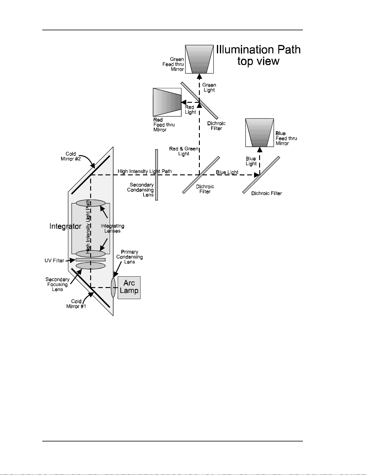
The Illumination Path
The illumination path is a very complex optical system of condensing lenses and
integrator lenses, reflective steering mirrors and Dichroic Filters, polarizing
optics, beamsplitters and combining prisms (see Figure 2-1 for physical layout).
The illumination path actually consists of two sections: the light path and the
image path. The light path begins with a light source, the Arc Lamp, then passes
through Primary Condensing Lens and is reflected off the #1IR Filter/Cold Mirror
where the infrared heat radiation is filtered out.
CAUTION!
mirror passes infrared light and its reflection contains only "cold' light that
does not transmit appreciable heat. As a result of the absorption of
infrared heat radiation, "cold" mirrors can get very hot.
The term "cold mirror" is used because the
From the #1 Cold Mirror the high intensity light passes through the Secondary
Focusing Lens, a UV Filter and into the Integrator, which consists of two “fly’s
eye” integrating lenses. The Primary Condensing Lens collects all the light from
2-2 Model 100 Service Manual
Page 15

Chapter 2---System Description
the Arc Lamp and begins to bend the light rays into a straight path. The Secondary
Focusing Lens works with the Primary Condensing Lens to collimate or
“straighten” the light path before it enters the Integrator. The UV Filter filters out
unwanted ultravioltet light.
After leaving the UV Filter the light passes through the Integrator. The function of
the Integrator is to spread out the beam so that it will have a more uniform
distribution of light across the face of the ILA®. This will result in a more
uniform image on the screen. After leaving the Integrator the white light is
reflected off the #2 IR Filter/Cold Mirror where more IR light is removed. The
white light then travels out to the Secondary Condensing lens and onto the
Dichroic Filters.
The Dichroic Filters divide the white light from the Arc Lamp into its three color
components, Red, Green and Blue. The first filter reflects the green and red light
and allows the blue light to pass through the beamsplitter and continue on to the
Blue Dichroic filter. The red and green light travel on to a second Dichroic Filter
where the red light is separated from the green light. The Blue Dichroic Filter
Mirror reflects the blue light into a Feedthru Beamsplitter. The red light is also
reflected from a Dichroic Filter into a Feedthru Steering Mirror and the green light
is transmitted through the beamsplitter into its respective Feedthru Beamsplitter.
All three light beams are reflected up into the Polarizing Beam Splitter.
Model 100 Service Manual 2-3
Page 16
Chapter 2---System Description
Figure 2-1
2-4 Model 100 Service Manual
Top View of lower level of Illumination Path for the Model 100.
Page 17
Chapter 2---System Description
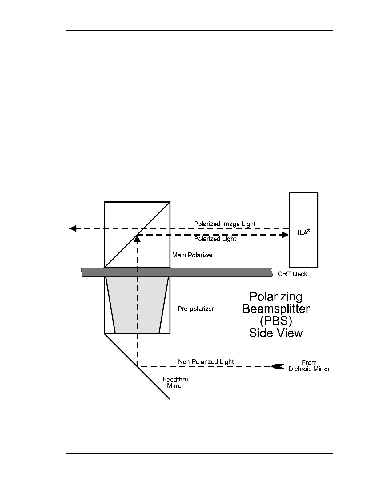
The Polarizing Beam Splitter (PBS) actually consists of a Pre-Polarizer and a
main Polarizer. The process of polarizing light is discussed in the following
paragraph.
Light can be viewed as having two electromagnetic components: a S-electric field
and a P-electric field. These fields are perpendicular to each other. When
unpolarized light travels through a polarizing beamsplitter one of these fields is
reflected and one is transmitted or passes through the beamsplitter. Upon striking
the Pre-Polarizer, the S-electric field is reflected and is wasted, the P-electric field
is passed through the Pre-Polarizing Beamsplitter and continues on to the Main
°
Polarizer. The Main Polarizing Beamsplitter is rotated 90
from the Pre-Polarizing
Beamsplitter so the P-electric field that was transmitted through the Pre-Polarizer
becomes the S-electric field and is reflected by the Main Polarizer. The reflected
polarized light, either red, green or blue, leaves the PBS and goes directly into the
®
ILA
device.
Figure 2-2
Side view of a Feedthru Beamsplitter and the Polarizing
Beamsplitter (PBS).
Model 100 Service Manual 2-5
Page 18
Chapter 2---System Description
The polarized light from each of the PBS’s enters the ILA® and is rotated and
modulated with the image signal. The amount the polarized light is rotated is
controlled by the ILA® bias and the amount of CRT light hitting the input side of
the ILA®, and translates directly to the brightness of the image on the screen.
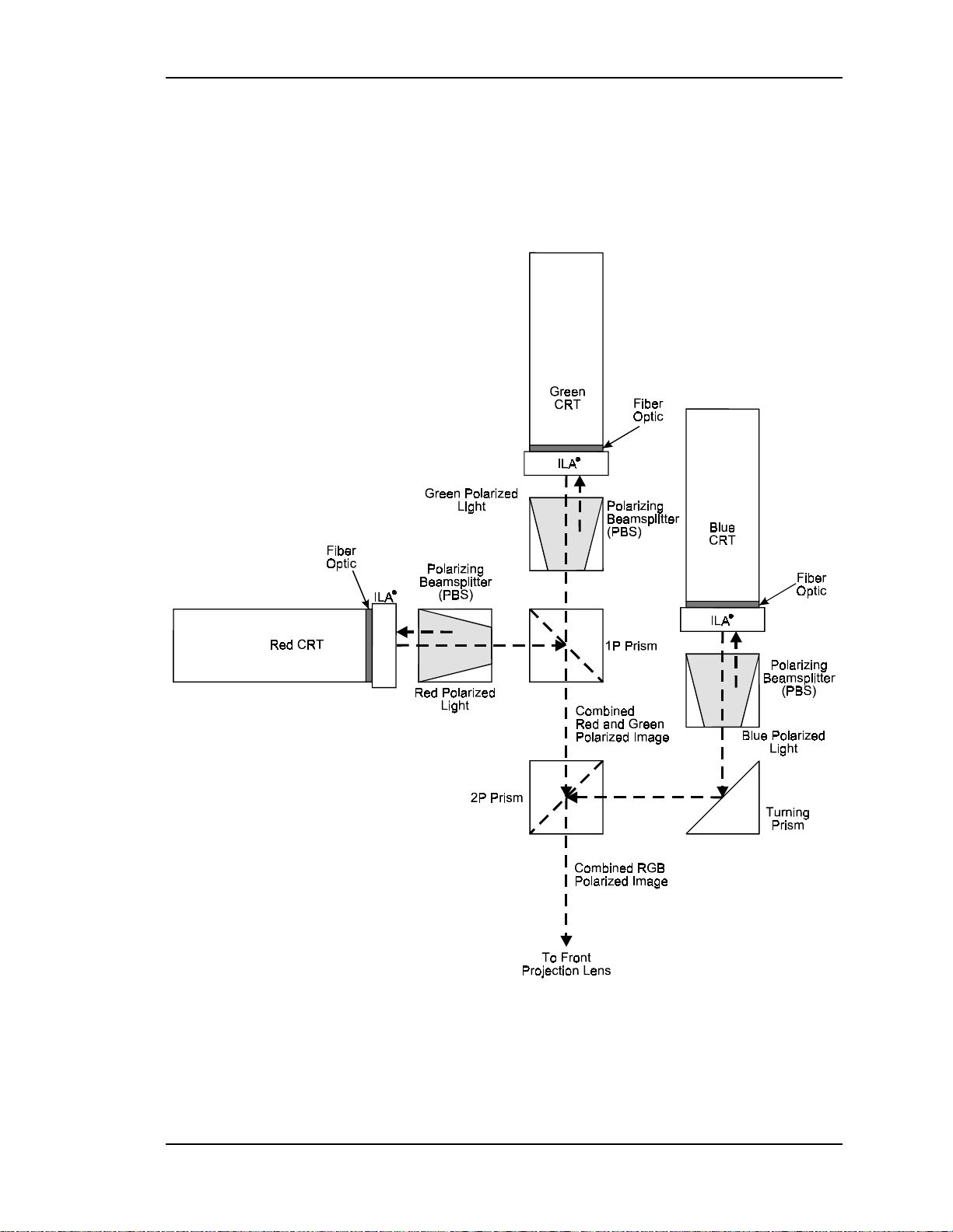
The image light from each of the ILA®s is then sent back through the Main
Polarizer portion of the PBS. The polarized blue image light continues on to a
Turning Prism where it is reflected into the 2P Combining Prism. The red and
green light come from their respective PBSs and are combined in the1P
Combining Prism. From the 1P Combining Prism, the red and green image light
go into the 2P Combining Prism to combine with the blue image light, where the
RGB image light goes through the Front Projection Lens and out onto the screen.
This completes the Illumination Path.
CAUTION!
critical. Replacement of individual mirrors or prisms requires removing the
projector cover and must be performed only by Hughes-JVC Certified
technicians. Consult the factory before removing or aligning any mirrors or
prisms.
The alignment of system optical components is
CRT \ ILA® Module
The three CRT/ILA® assemblies are located in the main body of the projector
above the Dichroic Filters and in front of the Electronics Module card cage. The
red CRT is separated and perpendicular to the green and blue CRT. Two exhaust
fans at the rear help cool the green and blue CRT assemblies. Each CRT is sent a
red, green, or blue image signal, but they do not emit a red, green, or blue color, as
in traditional CRT projectors. The CRTs are not used as a primary light source.
The light output to the screen is the function of the Arc Lamp, ILA® bias, and
CRT output. The purpose of the CRT is to generate an image and to control the
amount of modulation the ILA® assemblies introduce on the light coming from
the Arc Lamp. The Red, Green, and Blue image signals are routed to the CRTs
The
from the Video Amplifier Board through the CRT socket connectors.
image passes through a thin fiber-optic coating on the CRT face and another fiberoptic on the back surface of the ILA
®.
There is a thin layer of optical fluid
between the two fiber optic coatings. The input and output sides of the ILA
assembly are isolated from each other electrically and optically but are coupled
electrostatically.
At the same time the image is received at the input side of the ILA
®
side of the ILA® is receiving high intensity polarized light from the arc lamp
through the PBS. This high intensity polarized light is modulated by the image
from the CRT and the light polarization is rotated (90° at 100% CRT output) by
the liquid crystal on the output side of the ILA®. The light is then reflected back
CRT
®
, the output
2-6 Model 100 Service Manual
Page 19
Chapter 2---System Description
from the output side of the ILA®, and travels through the 1 and 2 Combining
Prisms (red and green). The blue polarized image light goes through the Turning
Mirror and combines with the red and green light in the #2 Combining Prism to be
picked up by the projection lens.
Figure 2-3
Model 100 Service Manual 2-7
Overhead view of top-level optical path.
Page 20
Chapter 2---System Description
Front Projection Lens
The Front Projection Lens picks up the high intensity image from the 2P
Combining Prism and transmits it to the projector screen. The Front Lens options
are:
!
Zoom Lens with a 3:1 to 8:1 range
!
1.5:1 Fixed Range Lens with a variable offset that can be set to 50% of
screen height above or below the centerline of the screen
!
1.1:1 Fixed Range Lens
WARNING!!!
The Xenon Arc Lamp produces high
intensity white, ultraviolet and infrared light capable of severe eye injury.
Never look directly at or touch the Xenon Arc Lamp. Service should
be performed by Hughes-JVC certified
technicians only.
2-8 Model 100 Service Manual
Page 21
Chapter 2---System Description
2.3 Electronics System
General Description
The Model 100 Electronics System includes nine printed circuit assemblies. They
provide all the controlling voltages and signals to adjust and correct picture
settings, geometry, convergence, and shading (see Chapter 4 of the User’s Guide).
The Electronics System also controls video and sync input signals, LED displays
on PCBs on the side of the projector, two RS-232 communications ports, and two
IR receivers for remote control of the projector.
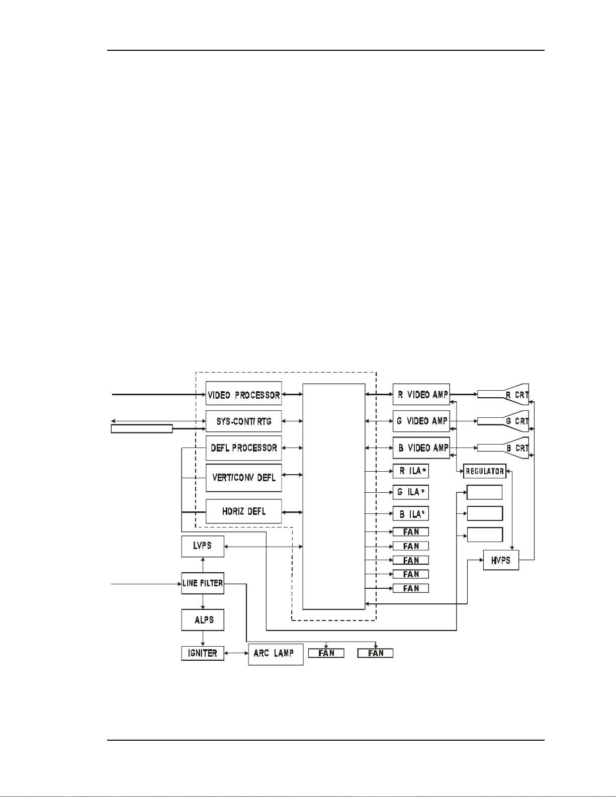
The descriptions in this portion of the manual are based on an overall Electronics
System block diagram and simplified block diagrams for each of the nine printed
circuit assemblies. The diagrams and descriptions serve two purposes; first, to
provide the technician with an overall grasp of how the system works and how
each assembly works with other assemblies in the system, second, to provide the
technician with enough information to troubleshoot to the assembly level, if
needed.
Figure 2-2 provides an overall System Block Diagram to show how the Optical
System, Arc Lamp, and Electronics System combine to provide the bright screen
image.
RGBVH
RS-232C / 422
IR RECEIVE
90-264 AC
50 / 60 Hz
BACKPLANE
R YOKE
G YOK E
FOCUS
B YOKE
RGB / HV
Figure 2-4
Model 100 Electronics System Block Diagram.
Model 100 Service Manual 2-9
Page 22
Chapter 2---System Description
Power Supplies
The Model 100 includes three power supply assemblies.
Low Voltage Power Supply
!
Arc Lamp Power Supply
!
High Voltage Power Supply
!
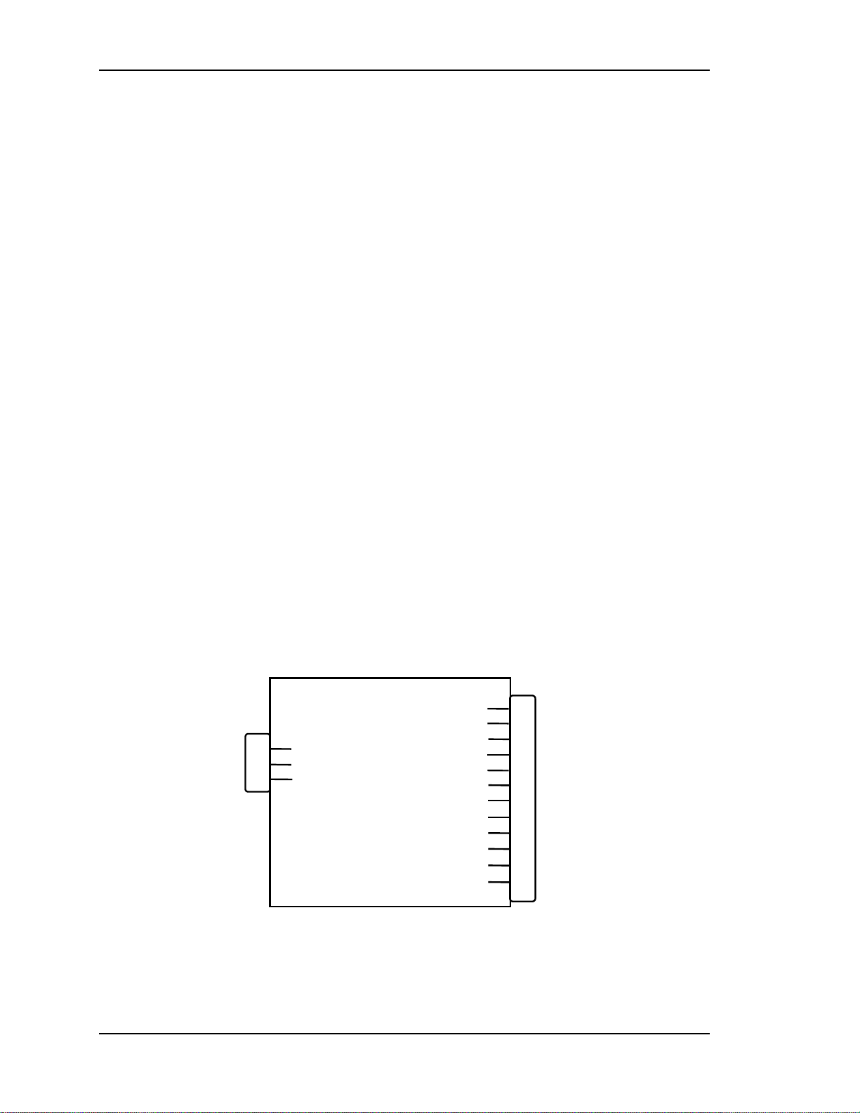
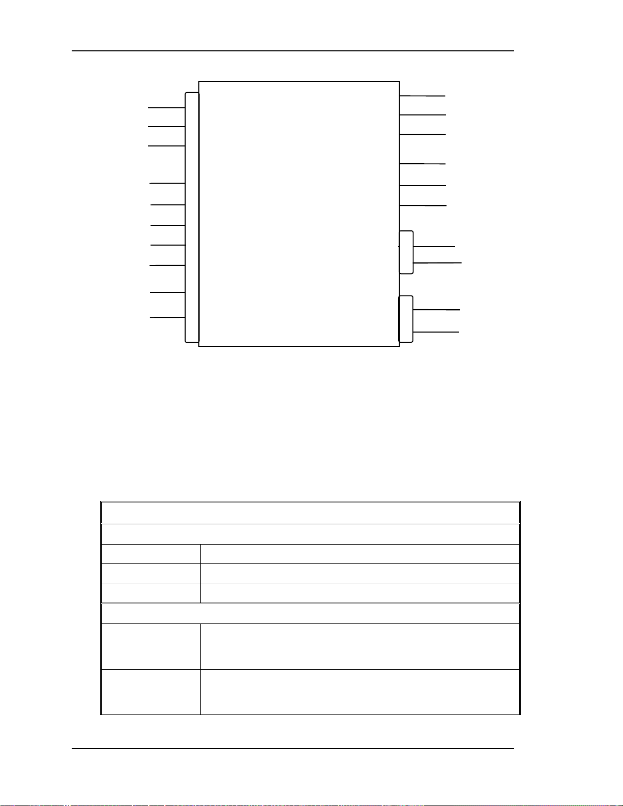
Low Voltage Power Supply (LVPS)
Main Functions:
!
Provides all of the analog, digital, and voltages needed by the projector.
!
Provides standby power when the projector is OFF.
!
Provides power for all cooling fans.
Operation:
The main power is filtered via the input filter to prevent radiation from escaping
back to the power line. From the line filter, AC power is fed into the Low Voltage
Power Supply module where AC is rectified, filtered, and compensated for power
factor correction.
The +5.1V Standby is on whenever AC power is connected to the projector and
the circuit breaker, next to AC power connection, is in the On position. The +24V
standby power for the fans turns on when the /FAN_ENA signal is received from
the System Controller (this turns off in 5-8 minutes if power is not turned on by
the remote control or a PC). All other voltages supplied by the LVPS are activated
when power is turned on at the remote or PC. These include +5.1V for digital
components, +6.2V for CRT filaments, ±15V for analog circuits, and the +80V
supply which is used by the High Voltage Power Supply, Video Amplifier PCB,
and the Horizontal Deflection PCB.
P76
AC
INPUT
P75
1
3
5
Line
Earth
Neutral
LV Ret
/LV_ENA
/LV_OK
+24v Fans
+5.1v STBY
+5.1v
+6.2v
+15V
-15v
+60V
/COVER_ON
/FAN_ENA
1-7
8
9
10
11
12
13
14
15
16
17
18
To P8 on
Backplane
Figure 2-5
LVPS Input/Output Diagram.
2-10 Model 100 Service Manual
Page 23
Chapter 2---System Description
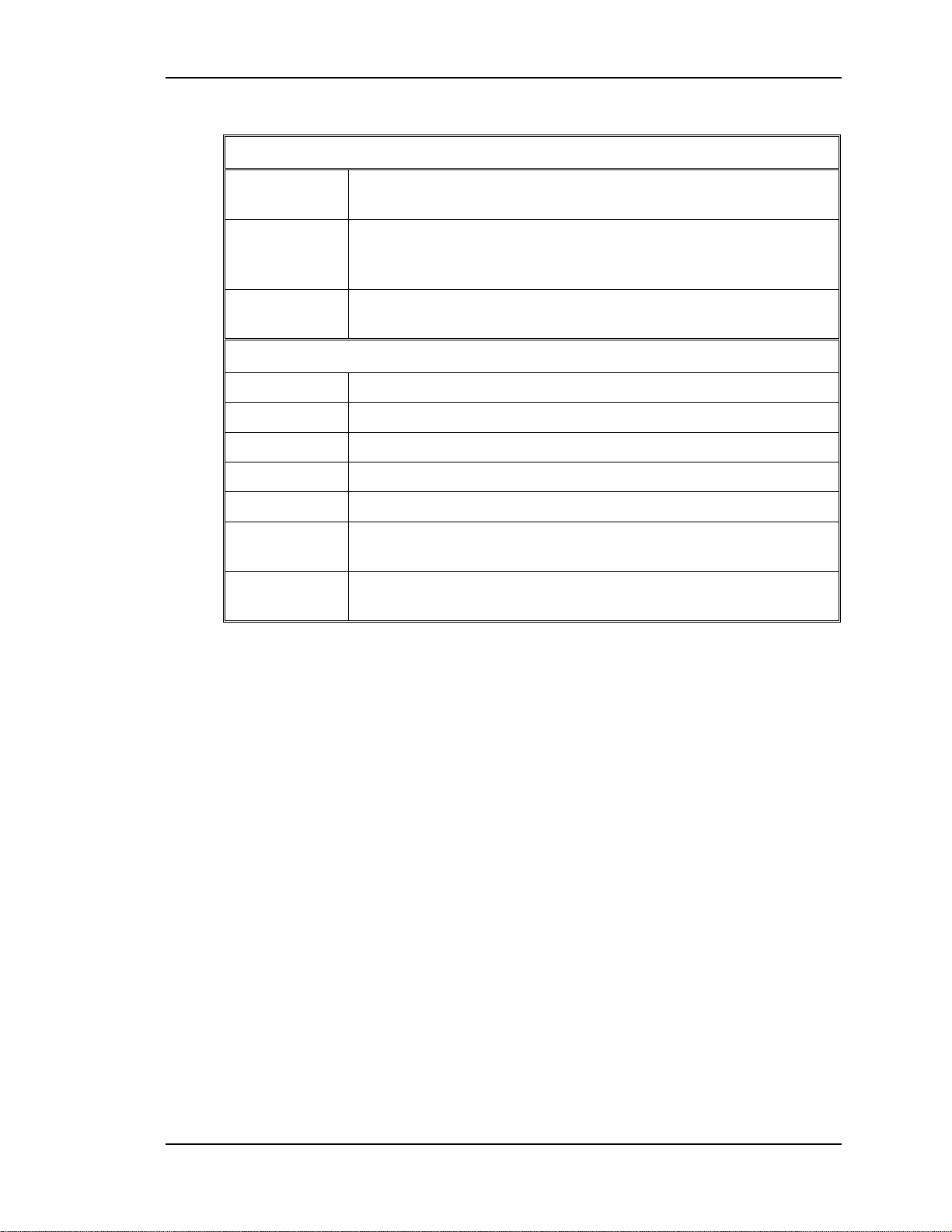
Table 2-1
Inputs and Outputs for the LVPS
Inputs
/ LV_ENA From System Controller/ RTG PCB - enables the LVPS when
the System Controller receives a Power-On command.
/ COVER ON Indicates the front cover is in place or the Interlock is in the
Service Mode. Enables the non-standby outputs. Also includes
Arc Lamp Thermal Shutdown Sensor signal.
/ FAN_ENA From System Controller/ RTG PCB - enables the +24 V
Standby voltage for the projector cooling fans.
Outputs
+24V To cooling fans
+5.1V +5.1 Stdby for CPU and remote operation.
+6.2V For CRT Filaments
+15V For analog circuitry
-15V For analog circuitr y
+60V For Horizontal power Supply section of Horizontal Deflection
PCB and Video Amplifiers PCB.
/ LV_OK Feedback signal indicating to the System Cont r oller, the status
of the non-standby supply (working or not working ).
NOTE:
a “/”in front of signal name means “active low“. This means the signal
will enable a device such as the LVPS in / LV_ENA. A high = 5V and low = 0V.
The /COVER_ON signal from the cover interlock switch tells the Low Voltage
Power Supply that the front cover is in place and the interlock switch is pressed
in. The /COVER ON signal also includes the Thermal Shutdown signal that
comes from a thermocouple attached to the Arc Lamp. If the Arc Lamp exceeds
°
130 ± 5
C or the Interlock Switch is not pushed in (or pulled out) the Low
Voltage Power Supply shuts down the projector.
Model 100 Service Manual 2-11
Page 24
Chapter 2---System Description
Arc Lamp Power Supply (ALPS)
Main Functions:
!
Provides a boost voltage of 150 Volts to Igniter Assembly. The Igniter
then delivers a 32 kV pulse to turn the Xenon Arc Lamp on.
!
Provides steady state power to maintain the lamp ON (approx. 19V at 39
Amps)
!
Current adjustable power supply (located on top of the power supply).
Operation:
The System Controller sends the /LAMP_ENA signal to the ALPS. The
/LAMP_ENA signal turns on the ALPS. The Arc Lamp Power Supply then
provides the +150 VDC boost voltage to the Laser Power Supply The Laser
Power Supply provides the spark gap to the Igniter Transformer (Igniter). The
Igniter steps up the +150 VDC boost voltage to approximately 32KV and ignites
the Xenon Arc Lamp. After the Arc Lamp is lit, it is maintained on by the ALPS
at a constant 19 volts and 39 amps. The /LAMP_LIT output signal informs the
System Controller if the lamp is lit or not. The Arc Lamp Power Supply is
shielded electrically and magnetically to prevent noise or disturbances in the
CRTs or other circuitry.
The / Cover On signal goes to the Arc Lamp Power Supply as well as the Low
Voltage Power Supply. If the Arc Lamp exceeds 130 ± 5° C or the Interlock
Switch is not pushed in (or pulled out) the Arc Lamp Power Supply shuts down.
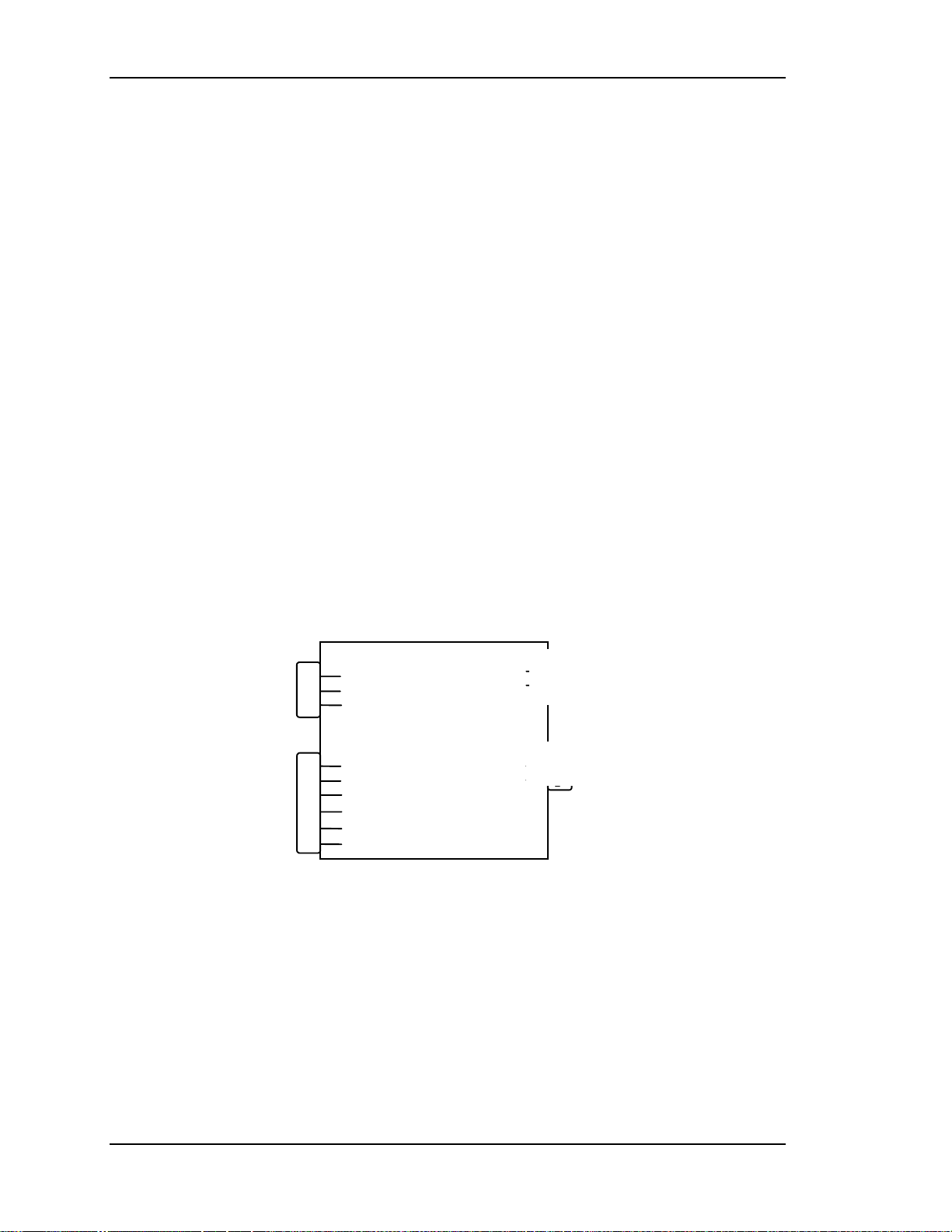
P74
1
2
To Arc
Lamp Igniter
To Arc Lamp
Igniter
P73
Jumper
Jumpered
1
2
A/C Input
To J106
Backplane
P71
AC
INPUT
1
3
5
P72
To J106
Backplane
1
2
3
4
5
6
Figure 2-6
Line
Earth
Neutral
GND
/LAMP_LIT
/LAMP_OK
/LAMP_ENA
/COVER_ON
GND
LAMP_OUT
LAMP_RET
LAMP_OK
GND
Arc Lamp Power Supply, Block Diagram.
2-12 Model 100 Service Manual
Page 25
Chapter 2---System Description
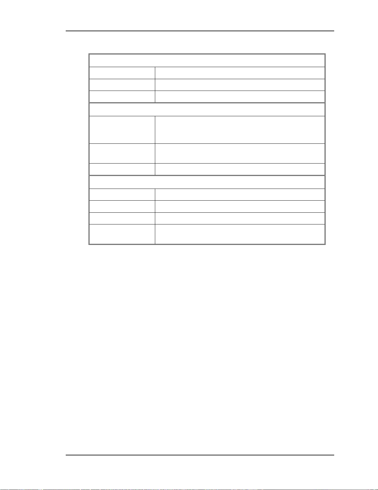
Table 2-2
Inputs and Outputs for the ALPS
A/C Inputs
LINE 90-132 Vac to 200-264 Vac at 50-60 Hz
EARTH Ground
NUETRAL Return
Inputs
/ COVER ON Indicates the front cover is in place or the Interlock is
in the Service Mode. Also includes Arc Lamp Thermal
Shutdown Sensor signal.
/ LAMP ENA Signal from System Controller/ RTG to turn on Arc
Lamp Power Supply
/ LAMP OK Jumpered to ground
Outputs
ARC LAMP OUT +150 V boost voltage to Igniter t o st ar t Arc Lamp
Normal Operation: +19 Volts at 39 Amps
ARC LAMP IN Arc Lamp return
/ LAMP LIT Feedback signal to System Controller / RTG that Arc
Lamp is lit
High Voltage Power Supply (HVPS)
The High Voltage Power Supply (HVPS) is located in front of the LVPS on the
left side of projector (as viewed from rear). This supply provides the anode, focus,
and screen voltages required for the three CRTs in the Model 100 projector.
The following functions are provided by HVPS:
!
Phase locked loop circuit for synchronization to the horizontal sync
!
Generation of anode voltages (15kV) for all three CRTs (RGB)
!
Generation of G3 focus voltage (3.5 to 4.5kV) for all three CRTs (RGB)
!
Generation of the G2 (supply-Black Level voltage for all three CRTs
!
Generation of G1 supply (Blanking) voltage
!
Dynamic focus amplifier using H and V parabolas
!
External ON/OFF and generation of /HV_OK signal
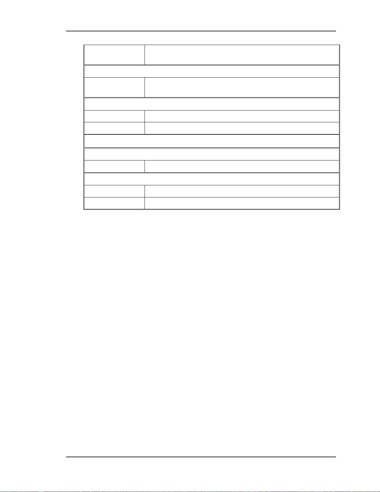
The High Voltage Power Supply I/O diagram (see Figure 2-7) and the list of
inputs and outputs (see Table 2-3), provide an understanding of the operation of
the HVPS to allow the technician to perform module level troubleshooting.
Model 100 Service Manual 2-13
Page 26
FROM SYSTEM
CONTROLLER
H VPS_SYNC
IIC CLK
IIC DATA
FROM LVPS
(VA_OK)
(
From VPB
/
+5V
+15V
+15V
-15
)
CN1
19
Chapter 2---System Description
R ANODE
5
9
11
12
13
17
20
HIGH
VOLTAGE
POWER
SUPPLY
G ANODE
B ANODE
R FOCUS
G FOCUS
B FOCUS
CN5
ARC GND
3
G2 SUPPLY
1
T
O
C
R
T
S
TO
REGULATOR
PCB
FROM
DEFLECTION
PROCESSOR
H FOCUS SIG
V FOCUS SIG
15
16
CN1 IS CONNECTED TO J104 BACKPLANE
CN5 IS CONNECTED TO CN201 REGULATOR PCB
CN1
14
18
G1 SUPPLY
/HV OK
TO
Figure 2-7
High Voltage Power Supply, I/O Diagram.
The HVPS Input/Output
This section provides a comprehensive description of the inputs to and outputs
from the HVPS. The I/O descriptions are arranged by the source/destination of the
signal. The format used is such that the assembly communicated with is used as
the primary heading of each output. Input refers to an input to the HVPS. Output
refers to an output from the HVPS. In each case the signals direction is noted.
Table 2-3
Inputs and Outputs for the HVPS
Inputs
LVPS
+15V Power for analog circuitry.
-15V Power for analog circuitry.
SYST
EM
CONT
+5.1V Power for digital circuitry.
SC/RTG
HVPS SYNC Synchronization pulse for the HVPS, synchronized with the
selected Horiz. Sync at either same, half or on t hir d the
frequency.
IIC DATA IIC data line. Bi- directional serial line for synchronous data
transfer between the SCB/RTG , the HVPS, video processing
and deflection processing PCBs.
2-14 Model 100 Service Manual
Page 27
Chapter 2---System Description
IIC CLK IIC clock line. Unidirectional clock line for control of
synchronous data transfer over the IIC bus interface.
Video Processor
/ VA OK (HV
Low enables HVPS
ENABLE)
Deflection Processor
H FOCUS SIG Horizontal focus parabola.
V FOCUS SIG Vertical Focus parabola.
Outputs
SC/RTG
/HV OK High Voltage status line. Low = HVPS operating normal.
Regulator
G1 SUPPLY -75V
G2 SUPPLY 1kV
Video Input Cards (VIC)
There is only one optional video input card slot on the Model 100. It is located
immediately to the right of the Video Processor PCB on the right side of the
projector. There are five Optional Video Input Cards that can be used with the
Model 100 Projector.
!
RGBHV Wide-Band VIC used as a second input card.
!
Graphics Enhancer RGB VIC
!
Four-Input RGB MUX VIC used in a similar manner as a switcher.
!
HDTV VIC used for High Definition Television.
!
Quad Standard Decoder/ Line Doubler VIC used for NTSC, PAL
SECAM and other composite sources.
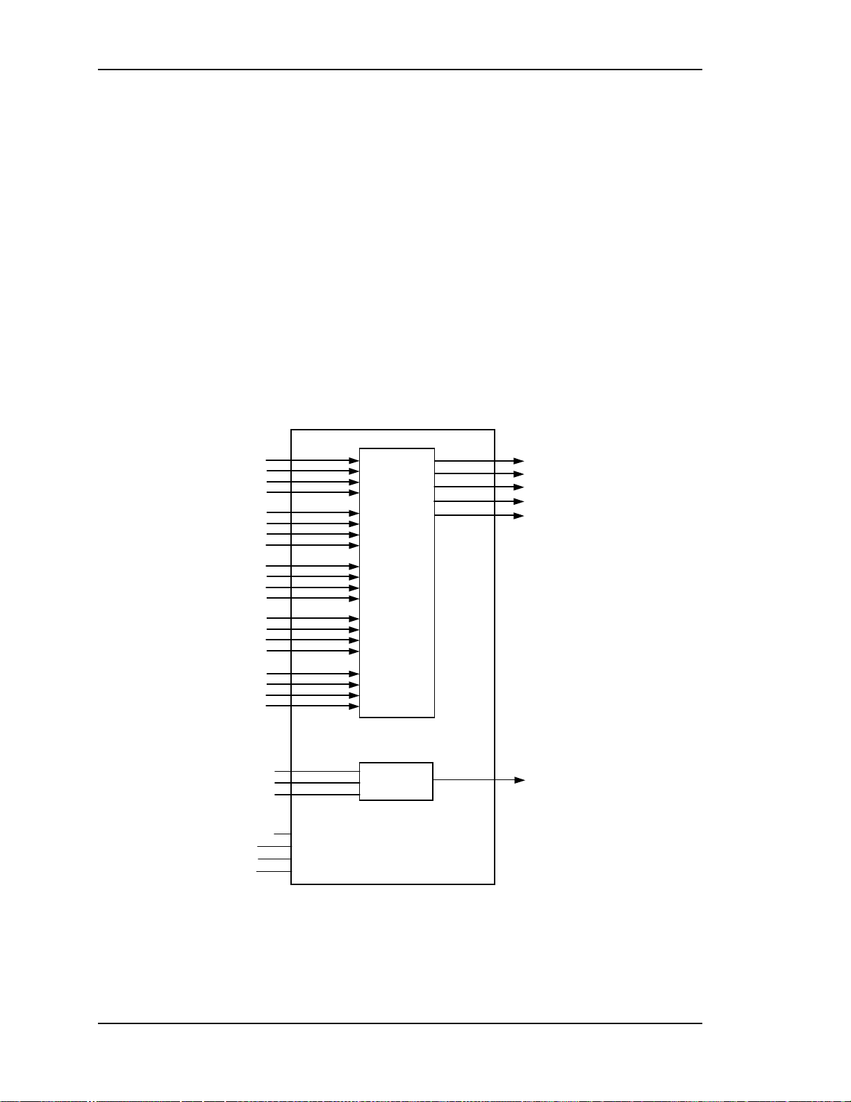
RGBHV Wide-Band VIC
The RGBHV Wide-Band VIC has five BNC inputs. It provides the RGB and HV
sync interface for the projector. This RGB VIC provides a high bandwidth
interface for the three color video signals. The video signals are routed to the
Backplane Board. The sync signals (horizontal and vertical) are also directly
connected to the Backplane Board.
The following functions are provided by the RGB VIC:
!
Video and sync interface for red, green and blue
!
LED indication
!
IIC serial bus interface
Model 100 Service Manual 2-15
Page 28
Chapter 2---System Description
LED indication
The RGB VIC includes an LED which is illuminated when the board is selected
(i.e. when the /SEL_CH line is low) as the input for the Model 100 Projector.
IIC serial bus interface section
The RGBHV Wide Band VIC is controlled by the serial bus interface. The IIC bus
comes from the System Controller Board through the Backplane Board. The
information transferred over the IIC bus is indicated below (I = input to the RGB
VIC, and O = output from the RGB VIC). The RGB VIC does not use the
interrupt line of the IIC bus interface:
RED
GREEN
BLUE
HORIZ
VERT
IIC_CLK
IIC_DATA
IIC_INT
+5.1V_STBY
+5.1V
+15V
-15V
B13
A13
A12
A16
B16
B15
B14
IIC
B2
RED_VIC
B4
GRN_VIC
B6
BLU_VIC
H_VIC
B8
V_VIC
B10
/SEL_VIC
12*
A1 GND
A2 GND
A3 GND
Figure 2-8
RGBHV Wide-Band VIC I/O.
The RGBHV Wide-Band_VIC I/O
This section provides a description of the inputs to and outputs from the
RGB_VIC. The I/O descriptions are arranged by the source/destination of the
signal. The format used is such that the assembly communicated with is used as
the primary heading of each group of signals. Those signals are further subdivided
into inputs and outputs. Input refers to an Input to the RGB_VIC, output refers to
an output from the RGB_VIC.
2-16 Model 100 Service Manual
Page 29
Chapter 2---System Description
Table 2-4
Projector Inputs
Inputs
RED
GREEN
RGBHV Wide-Band VIC I/O signals
Description
Video input signals. about 0.7 to 1VPP
BLUE
HORIZ.
VERTICAL
Video Processor PCB
Outputs
/SEL_VIC
RED_VIC
Horizontal or composite sync signal
Vertical sync signal
Description
Select line for VIC. A low indicates the RGB_VI C is selected.
Video signals. about 0.7 to 1VPP
GRN_VIC
BLU_VIC
H_VIC
V_VIC
Horizontal or composite sync signals
Vertical sync signals
System Controller / RTG PCB
Description
Inputs
IIC_CLK
IIC clock line. Unidirectional clock line for control of
synchronous data transfer over the IIC bus interface.
IIC_DATA
IIC data line. Bi-directional serial line f or synchronous dat a
transfer between System Controller/ RTG PCB and the
RGB_VIC.
Description
Outputs
/IIC_INT
Low Voltage Power Supply
Inputs
+5.1V
+15V
-15V
+ 5.1
IIC interrupt line. RGB_VI C does not initiate an interrupt.
Description
+5.1V supply for use by RGB_VIC.
+ 15V supply for use by RGB_VIC.
-15V supply for use by RGB_VIC.
+ 5.1V standby supply for use by RGB_VIC.
V_STBY
Model 100 Service Manual 2-17
Page 30
Chapter 2---System Description
Graphics Enhancer RGB VIC
The Graphics Enhancer RGB VIC is the same as the RGBHV Wide-Band VIC
except that it has a Graphics Enhancer chip that allows some adjustment to
enhance small black text on a white background. This adjustment is discussed in
section 3.18 of this manual. Refer to the RGBHV Wide-Band VIC section for
inputs and outputs.
Four-Input RGB VIC
The Four-Input RGB VIC consists of four sets of RGBHV inputs and operates in
a manner similar to a switcher. The four inputs are multiplexed so that only one is
enabled at a specific time. Software selects the desired input channel through the
IIC bus and ensures that only one RGB VIC is enabled. When one of the channels
assigned to the Four-Input RGB VIC is selected, the /SEL_VIC line to the Video
Processor is enabled.
RED_CH1
RED_CH2
RED_CH3
RED_CH4
GRN_CH1
GRN_CH2
GRN_CH3
GRN_CH4
BLU_CH1
BLU_CH2
BLU_CH3
BLU_CH4
HOR_CH1
HOR_CH2
HOR_CH3
HOR_CH4
VER_CH1
VER_CH2
VER_CH3
VER_CH4
IIC_CLK
IIC_DATA
IIC_INT
+5.1Vstby
+5.1V
+15V
-15V
4:1
VIDEO
MUX
and
BUFFERS
IIC
RED_VIC
GREEN_VIC
BLUE_VIC
H_VIC
V_VIC
/SEL_VIC
Figure 2-9
Four-Input RGB VIC I.O Diagram.
The same functions performed by the RGB VIC are performed by the Four-Input
RGB VIC. The description of operation and pinouts are the same as the Graphics
2-18 Model 100 Service Manual
Page 31

Chapter 2---System Description
Enhancer RGB VIC. One of four LEDs indicates which of the four RGB inputs is
currently active.
YPbPr VIC
YPbPr is a high-end video signal standard. The HDTV YPbPr VIC converts the
YPbPr component signal to a RGBHV type video signal. It contains three BNC
input connectors that can be used for two different inputs, YPbPr or GBR.
The following functions are provided by YPbPr_VIC:
!
Video input and output buffers
!
Conversion of YPbPr signal format to RGB signals format
!
Separation of syncs from the Y/G input signal
!
Hue, sharpness, gamma, and color adjustment
!
Selection of RGB component input or YPbPr input
!
LED indication
!
IIC serial bus interface
This VIC accepts two types of video signals, color components (YPbPr) and RGB
signals. In either case, the output of this VIC is RGB type signal. If the inputs are
color components they will be converted to RGB type signals.
The selection between color component input mode and RGB input mode is
controlled by an input. This input is controlled by the System Controller/RTG
PCB via the IIC serial bus interface.
LED indication
There are two LEDs on this VIC. The RGB LED is illuminated when the
YPbPr_VIC is selected and is in RGB input mode. The YPbPr LED is illuminated
when the YPbPr_VIC is selected and is in YPbPr input mode. Both LEDs are off
when the YPbPr_VIC is not selected as the input to projector. Only one LED can
be on at one time.
IIC Interface
The YPbPr_VIC is controlled by the serial bus interface. The IIC bus comes from
the System Controller Board through the Backplane Board. All required
adjustments for this board are provided via the IIC serial bus interface. The
information transferred over the IIC bus is indicated below (I = input to
YPbPr_VIC, and O = output of YPbPr_VIC). The selection of this VIC is
accomplished through the IIC control bus which provides the /SEL_VIC signal.
Model 100 Service Manual 2-19
Page 32

Chapter 2---System Description
Y/G
Pb/B
Pr/R
IIC_CLK
IIC_DATA
+5.1V_STBY
+5.1V
+15V
-15V
B13
A13
A16
B16
B15
B14
B2
B4
B6
B8
B12
RED
GRN
BLU
HOR
/SELECT
Figure 2-10
YPbPr VIC I/O Diagram.
The YPbPr_VIC I/O
This section provides a comprehensive description of the inputs to and outputs
from the YPbPr_VIC. The I/O descriptions are arranged by the source/destination
of the signal. The format used is such that the assembly communicated with is
used as the primary heading of each group of signals. Those signals are further
subdivided into inputs and outputs. Input refers to an Input to the YPbPr_VIC,
output refers to an output from the YPbPr_VIC.
Table 2-5
Projector Inputs
Input
Y/G
Pb/B
YPbPr VIC Signals
Description
Video input signals-about 0.7 to 1 VPP
Pr/R
Video Processor PCB
Description
Output
/SELECT
Selection indicator for VIC. Low indicates the selected
YPbPr_VIC.
2-20 Model 100 Service Manual
Page 33

Chapter 2---System Description
RED
Video signals. about 0.7 to 1 VPP
GRN
BLU
HOR
System Controller Board / RTG PCB
Inputs
IIC_CLK
Composite horizontal / vertical sync signal
Description
IIC clock line. Unidirectional clock line for control of synchronous
data transfer over the IIC bus inter face.
IIC_DATA IIC data line. Bi-directional serial line f or synchronous data
transfer between system control board and the YPbPr _VIC.
Outputs
/IIC_INT
Low Voltage Power Supply
Inputs
+5.1V
Description
IIC interrupt line. YPbPr_VI C does not initiate any interrupt
Description
+5.1V supply for use by YPbPr_VIC.
+15V
-15V
+ 15V supply for use by YPbPr_VIC.
-15V supply for use by YPbPr_VIC.
Quad Standard Decoder/ Line Doubler VIC
The Quad Standard Decoder/ Line Doubler VIC has two basic functions. The
Quad Decoder accepts C-Vid and S-Vid signals in four different formats PAL,
SECAM NTSC and 4.43NTSC and converts them to a RGBHV signal. It contains
one BNC input connector for C-Video and two BNC connections for Luminance
(Y) and Chrominance (C) for S-Video. The Model 100 projector does not accept
sources with horizontal scan frequencies lower than 30 kHz. The Line Doubler
takes scan frequencies like NTSC (~15 kHz) and doubles it to ~31 kHz, which the
Model 100 can use.
The following functions are provided by the Quad Standard Decoder/ Line
Doubler VIC:
!
Select input source - Composite or S-video
!
Select standard-AUTO/NTSC/PAL/SECAM/4.43NTSC
!
Conversion of composite and S-video signals to RGB video signals
!
Separation of syncs from the input signal
!
Doubles the Horizontal Scan Frequency
!
Tint, sharpness, and color adjustment
Model 100 Service Manual 2-21
Page 34

!
LED indication of Composite or S-video
!
IIC serial bus interface
Chapter 2---System Description
Comp
Y in
C in
IIC_CLK
IIC_DATA
+5.1V
+15V
B16
Figure 2-11
B13
A13
B15
Quad Standard Decoder/ Line Doubler I/O Diagram.
B2
B4
B6
B8
B10
B12
R
G
B
/H
/V
/SELECT
LED Indication
There are two LEDs on this VIC. The LED on the right side of the board is
illuminated when Composite Video is selected and the LED on the left is
illuminated when S-Video is selected. Only one LED can be illuminated at one
time.
IIC Interface
The Quad Standard Decoder/ Line Doubler VIC is controlled by the serial bus
interface. The IIC bus comes from the System Controller Board through the
Backplane Board. All required adjustments for this board are provided via the IIC
serial bus interface. The information transferred over the IIC bus is indicated
below (I = input to YPbPr_VIC, and O = output of YPbPr_VIC). The selection of
this VIC is accomplished through the IIC control bus which provides the
/SEL_VIC signal.
Quad Standard Decoder/ Line Doubler VIC I/O
This section provides a description of the inputs to and outputs from the Quad
Standard Decoder VIC. The I/O descriptions are arranged by the
source/destination of the signal. The format used is such that the assembly
communicated with is used as the primary heading of each group of signals. Those
signals are further subdivided into inputs and outputs. Input refers to an Input to
the VIC, output refers to an output from the VIC.
2-22 Model 100 Service Manual
Page 35

Chapter 2---System Description
Table 2-6
Projector Inputs
Input
Composite
Quad Standard Decoder/ Line Doubler VIC Signals
Description
Video input signals-about 0.7 to 1VPP
Video
S-Video Y,
C,
System Controller Board
Inputs
IIC_CLK
Video input signal-about 0.7 to 1VPP f or Luminance and
about .3-.6 VPP for Chrominance (C)
Description
IIC clock line. Unidirectional clock line for control of
synchronous data transfer over the IIC bus interface.
IIC_DATA IIC data line. Bi-directional serial line f or synchronous dat a
transfer between SC/ RTG PCB and the VIC.
/ IIC_SINT IIC Interrupt (Output
Low Voltage Power Supply
Description
Inputs
+5.1V
+15V
-15V
GND
Video Processor Board
Output
/SELECT
+5.1V supply for use by The Quad Decoder VIC.
+ 15V supply for use by the Quad Decoder VIC.
- 15V supply for use by the Quad Decoder VIC.
Ground
Description
Selection indicator for VIC. Low indicates the Quad VIC is
selected.
RED
Video signals. about 0.7 to 1VPP
GRN
BLU
H / C
V_VIC
Horizontal Composite input signal, about 1-1. 25VPP
Vertical sync input signal to Video Processor.
Model 100 Service Manual 2-23
Page 36

Chapter 2---System Description
Video Processor PCB
The Video Processor PCB (VP PCB) is the bottom-most card (see Figure 4-10) in
the card cage. It is connected directly to the Backplane board through 2
connectors. When an external signal is being received, the VP-PCB provides
Horizontal Sync, Vertical Sync, and Green Sync signals to the System Controller /
Raster Timing Generator (SC/RTG) Printed Circuit Board (PCB). It also provides
three primary color signals, and G2 Control, and DC RESTORE signals to the
Video Amplifier PCBs (VA PCBs).
The following functions are provided by the VP PCB:
!
Video signal input and multiplexing
!
Sync signal stripping
!
Overlay signal multiplexing
!
Brightness and Contrast control, and DC RESTORE
!
On-screen Switching
!
Video signal gamma correction
!
Sensitivity and Threshold signal input and control
!
Automatic CRT Protection by limiting Contrast Amplifiers.
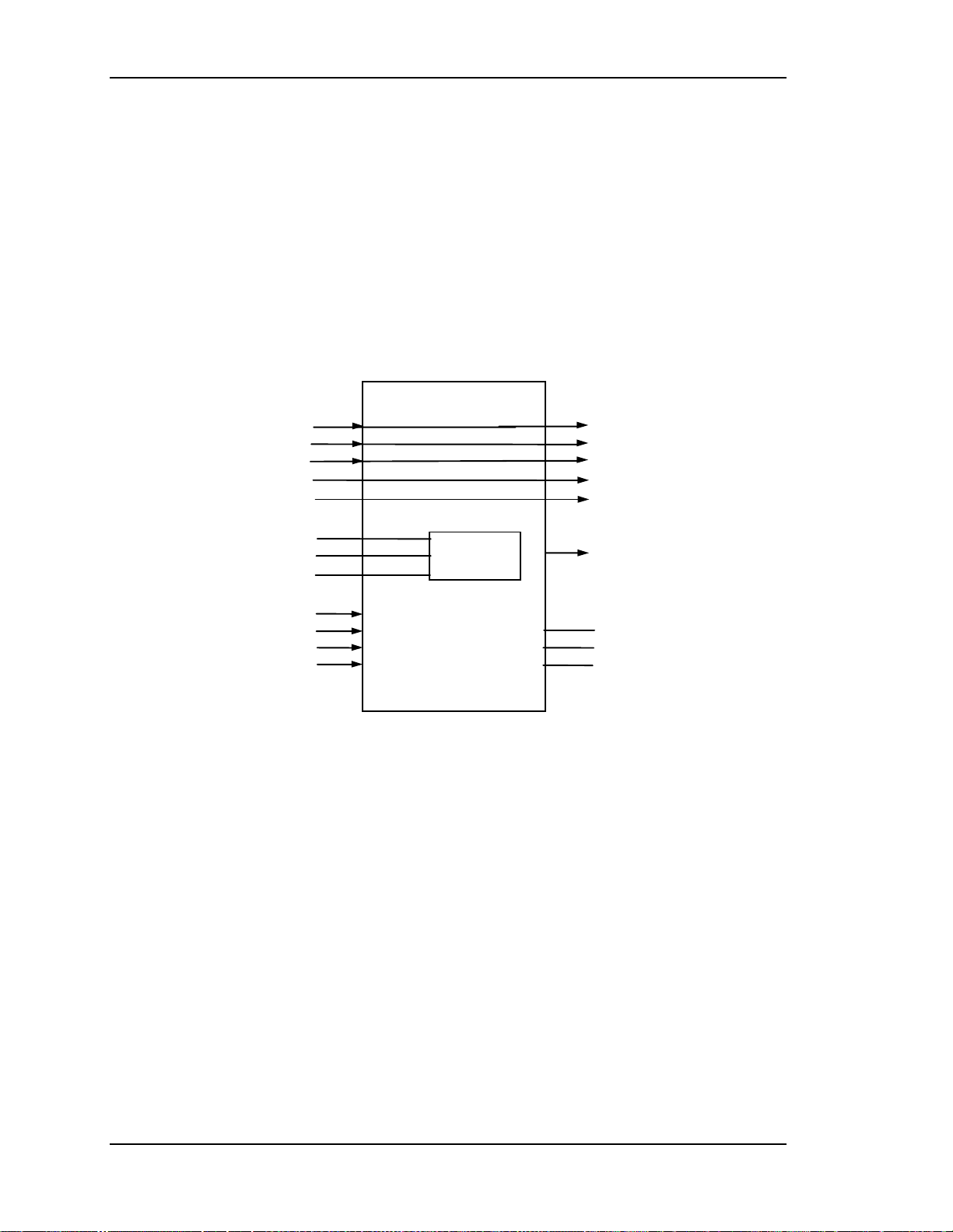
The Video Processor I/O diagram and the list of inputs and outputs provide
information to allow the technician to perform module-level troubleshooting.
2-24 Model 100 Service Manual
Page 37

Chapter 2---System Description
Figure 2-12
Video Processor I/O
This section provides a comprehensive description of the inputs to and outputs
from the Video Processor PCB. The I/O descriptions in Table 2-7 are arranged by
the source/destination of the signal. The format used is such that the assembly
communicated with is used as the primary heading of each group of signals. Those
signals are further subdivided into inputs and outputs. Inputs refers to an input to
the Video Processor PCB, while output refers to an output from the Video
Processor PCB.
Table 2-7
Video Processor I/O signals
Video Processor I/O Diagram.
Video Processor PCB
2.4 Input
Description
s
+15V Power for analog circuitry.
Model 100 Service Manual 2-25
Page 38

Chapter 2---System Description
Video Processor PCB
-15V Power for analog circuitry.
+5.1V Power for digital circuitry.
SC/RTG
Red Sens. Sensitivity correction information for Blu. Real time data at
0 volt to 1 volt.
Grn Sens. Similar to Red Sens.
Blu Sens. Similar to Red Sens.
Red Thres. Threshold correction information for blue. Real time data at
0 volt to 1 volt.
Grn Thres. Similar to Red Thres.
Blu Thres. Similar to Red Thres.
Red Over Red signal of on-screen menu and/or internal test pat t er n.
Grn Over Similar to Red Over.
Blu Over Similar to Red Over.
Overlay Overlay control signal.
IIC DATA IIC data line. Bi- dir ectional serial line for synchronous data
transfer between the SCB/RTG , HVPS, video processing
and deflection processing PCBs.
IIC CLK IIC clock line. Unidirectional clock line for control of
synchronous data transfer over the IIC bus interface.
IICS IRQ Interrupt line.
Video Processor PCB
BLANKING Blanking signal composed of right, left, t op and bottom
blanking.
CLAMP A negative-going video clamp sig nal with about 3 % dut y
cycle.
Video Amplifier PCB
/Red VAMP_OK Signal from the Regulator that the Red Video Amplifier is
working.
/Grn VAMP_OK Similar to Red VA OK.
/Blu VAMP_OK Sim ilar to Red VA OK.
Red Beam Voltage signal proportional to cathode current averaged
over several horizontal lines in the red CRT. Voltage level
is + mV/mA.
2-26 Model 100 Service Manual
Page 39

Chapter 2---System Description
Video Processor PCB
Grn Beam Similar to Red Beam .
Blu Beam Similar to Red Beam.
Video Input Card
/Sel VIC Input signal from RGB VIC that is used to select input video
source.
V VIC Vertical sync input signal from VIC.
H/C VIC Horizontal Com posite input signal.
Red VIC Red video input from VIC.
Grn VIC Green video input from VIC.
Blu VIC Blue video input from VIC.
/VA OK (HV
ENABLE)
After signal is received that the Video Amplifiers are
functional, this signal is sent t o enable the HVPS.
Outputs
Video Amplifiers
Red Video Red video output . 0 Volt to 1 Volt.
Grn Video Similar to Red Video.
Blue Video Similar to Red Video.
Restore DC Restore control signal.
SC/RTG
Grn sync Input vertical sync.
H sync Input Horizontal or composite sync.
V sync Sync on green signal that is stripped from t he green video.
/IIC Sint IIC interrupt line.
Regulator
Red G
2
Red CRT G2 voltage adjust control signal.
Grn G
2
Similar to Red G2.
Blu G2 Similar to Red G2.
/ Video Ok Signal sent to Regulator and Video Amplifier that a video
signal is present at the VIC.
Model 100 Service Manual 2-27
Page 40

Chapter 2---System Description
System Controller/ Raster Timing Generator PCB
The System Controller/ Raster Timing Generator (SC/RTG) is located in the
electronic card cage (see Figure 4-1).
The Electronics System is controlled by the SC/RTG PCB. The SC/RTG PCB
uses digital and analog circuits to direct the operation of image and raster
generation circuits and to control the input/output of power supply operation. The
SC/RTG can be viewed in two sections: the System Controller section and the
Raster Timing Generator section
The System Controller section sets the operating parameters of the image, such as
brightness and contrast. It also produces internal test patterns and generates onscreen display overlays. The SC/RTG PCB sets the timing for the raster
generation to adjust phase, geometric corrections, shading corrections, and
convergence. The program memory and the memory for all convergence and
shading maps are located on the SC/RTG PCB.
The following functions are performed or controlled by the System Controller
section of the System Controller / Raster Timing Generator PCB:
!
Enables control for the Low Voltage Power Supply, Arc Lamp and cooling
fans.
!
Fault monitors the HVPS, LVPS, Arc Lamp, and fans and most of the
other PCBs.
!
Provides interface communication via the IIC serial bus.
!
Controls Zoom and Focus of the Projection Lens.
!
IIC Interface control
!
Provides Video Overlays such as Menus and Internal Test Patterns
!
X and Y convergence control
!
Threshold and Sensitivity for shading
!
I/O control
!
Two RS-232 serial interface ports
!
Infrared (IR) remote control interface. Accepts input from front or rear IR
detectors.
!
A 5-wire JTAG interface port for CPU emulation support.
!
External 3 color system status LEDs. Green indicates normal, yellow is
standby and red indicates a fault condition.
!
External Service Mode Switch (see Figure 3-12). Pressing this switch
while turning on Circuit Breaker allows the technician to get into the
Buffer Memory. This allows the loading of new operation software and
boot manager.
2-28 Model 100 Service Manual
Page 41

Chapter 2---System Description
!
System Reset Switch. Resets the entire projector must be turned back on.
No data loss.
!
Front Lens control (Focus, Zoom, and Memory Position).
!
ILA® Shutter control.
!
CCD Camera control for Autoshading (future use).
The following functions are performed or controlled by the Raster Timing
Generator section of the System Controller / Raster Timing Generator PCB:
!
Provides the ability to handle sources with the following horizontal and
vertical scan frequencies
Horiz. (30-135 kHz)
"
Vert. (50-150 Hz)
"
!
Selects the proper sync from the source (Separate H&V, Comp sync, and
SOG).
!
Removes the serration and equalization pulses from the Composite. and
Sync On Green syncs.
!
Generates the back porch clamping signal.
!
Detects Non-interlaced and Interlaced sources.
!
Separates horizontal and vertical syncs and provides horizontal and
vertical phase adjustment.
!
Generates blanking signals (left, right, top, and bottom).
!
Provides internal sync generation
!
Provides timing signals used by the System Controller section, and the
Horizontal and Vertical Deflection areas.
Model 100 Service Manual 2-29
Page 42

Chapter 2---System Description
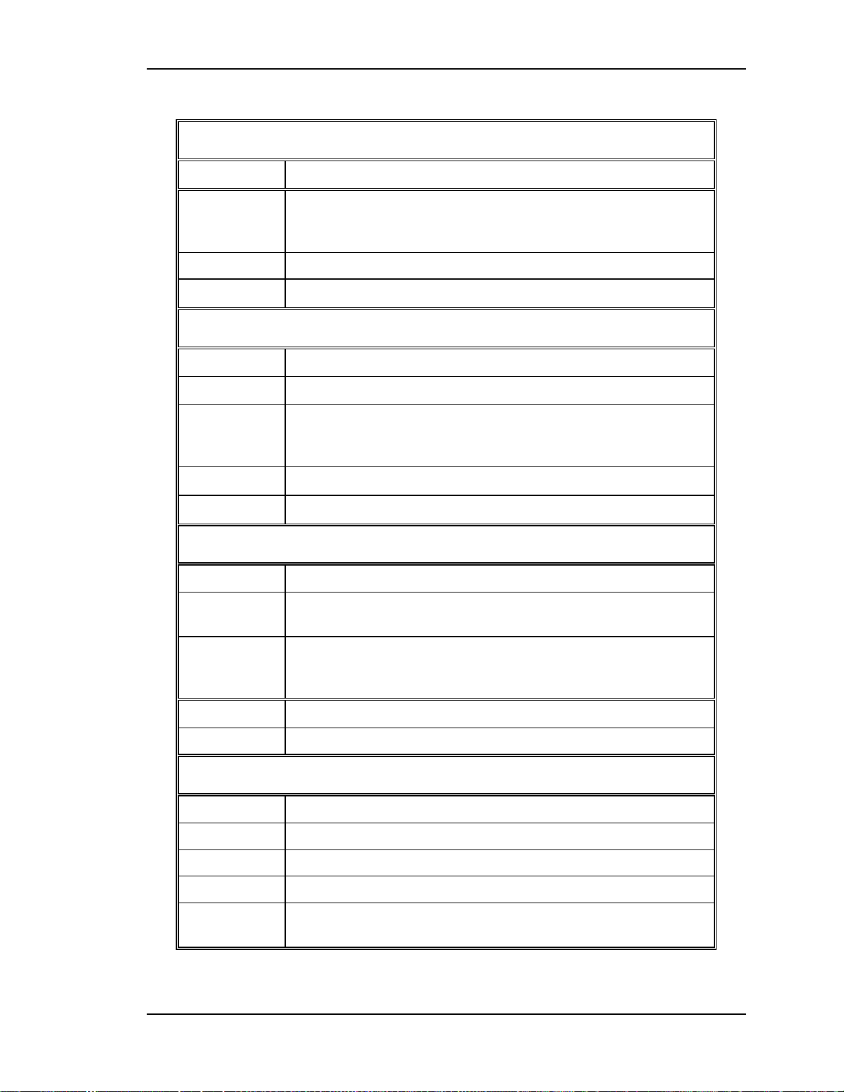
The SC/RTG I/O diagram (see Figure 2-13) and the list of Inputs and Outputs
(see Table 2-8) provide information for the technician to perform module-level
troubleshooting.
Figure 2-13
I/O Diagram of System Controller section of SC/RTG PCB.
IIC Interface
Communications are performed through the IIC bus to the other PCBs in the
system. This three-wire bus interface consists of clock line, data line and interrupt
line. The System Controller PCB controls the IIC bus and tells the other PCB
when to send and receive data over the IIC bus.
System Controller / Raster Timing Generator Input/Output
This section provides a description of the inputs to and outputs from the SC/RTG.
The I/O descriptions are arranged by the source/destination of the signal. The
format used is such that the assembly communicated with is used as the primary
heading of each output. Input refers to an input to the SC/RTG, output refers to an
output from the SC/RTG.
2-30 Model 100 Service Manual
Page 43

Chapter 2---System Description
Table 2-8
System
System Controller/ RTG PCB input/output signals
Controller
/Raster Timing Generator PCB
Inputs
LVPS
+5.1V Stdby Standby voltage for microprocessor contr ol and r emote
+15V Power for analog circuitry.
-15V Power for analog circuitry.
/LV OK Feedback signal from t he LVPS t hat it has powered up.
HVPS
HV OK High Voltage status line. Low = operation HVPS.
ALPS
/LAMP OK
/LAMP LIT Signal from ALPS that t h e Ar c Lamp is lit.
Video Processor
Description
operation.
Jumpered (not used).
V Sync Input vertical sync.
H Sync Input Hor izontal or com posit e sync.
Grn Sync Sync on grn signal that is stripped from the green video.
Misc.
/FRONT IR Input signal from Front IR Detector.
/REAR IR Input signal from Rear IR Detector.
LENS POS
CCD LINE Power to CCD AST camera.
CCD DATA Data from CCD AST camera.
Outputs
LVPS
/LV ENA Signal to enable the LVPS.
/FAN_ENA Signal to enable the 24V standby power.
Model 100 Service Manual 2-31
Page 44

Chapter 2---System Description
System Controller/Raster Timing Generator PCB
HVPS
Synchronization pulse for the HVPS, synchronized wit the
HVPS SYNC
ALPS
/LAMP ENA Enables the ALPS power.
Video Processor
OVERLAY Overlay control signal.
Red_Over Red signal of on-screen menu and/or internal t est pattern.
Grn_Over Similar to Red_Over.
Blu_Over Similar to Red_Over.
selected Horiz. Sync at either same, half or on t hir d the
frequency.
Blu_Thres
Grn_Thres Similar to Blu_Thres.
Red_Thres Similar to Blu_Thres.
Blu_Sens
Grn_Sens Similar to Blu_Sens.
Red_Sens Similar to Blu_Sens.
BLANKING Blanking signal composed of right, left , top and bottom
CLAMP A neg at ive-g oing video clamp signal wit about 3 % duty
Vertical Convergence Deflection
X_Red Conv
X_Red Conv
Threshold correction information for blue. Real time data at
0 volt to 1 volt.
Sensitivity correction information for Blu. Real time data at
0 volt to 1 volt.
blanking.
cycle.
Red X convergence waveform. The amplitude for full scale
correction is about 1 VPP.
Grn X convergence waveform. The am plitude for full scale
correction is about 1 VPP.
X_Red Conv
Y_Red Conv
Y_Grn Conv
2-32 Model 100 Service Manual
Blue X convergence waveform. The amplit ude for full scale
correction is about 1 VPP.
Red Y convergence waveform. The amplitude for full scale
correction is about 1 VPP.
Grn Y convergence waveform. The amplit ude for full scale
correction is about 1 VPP.
Page 45

Chapter 2---System Description
System Controller/Raster Timing Generator PCB
Y_Blu Conv
Deflection Processor
CORR SYNC
V DRIVE
Horizontal Deflection
H DRIVE
H BAND:0 Horizontal frequency band lines.
H BAND:1 Band A = 00, Band B = 01, Band C = 11.
/H ENABLE Low = enabled deflection and high = disabled deflection.
H_F2V A DC voltage proportional to horizontal frequency.
CCD Camera
CCD_EXP Signal to CCD Shading camera to control shutter
Blue Y convergence waveform. The amplitude for full-scale
correction is about 1 VPP.
Square wave HCT level synchronous signal for Horiz.
Axis.
Square wave negative going pulse synchronized to the
selected vertical sync with a pulse width of about 4
horizontal periods.
Square wave 50 % duty cycle synchronized to the
selected horizontal sync.
exposure time.
CCD_CLK Clock pulse for CCD Shading camera.
CCD_ZOOM Signal to CCD Shading camer a for zoom control.
CCD_FOCUS Signal to CCD Shading camera for focus control.
CCD_IRIS Signal to CCD Shading camera fo r aper ture control.
Front Lens
LENS_ZOOM Signal to lens zoom motor.
LENS_FOCUS Signal to lens focus motor.
Shutters
Red Shutter Signal to actuate the Red Shutter Motor.
Grn Shutter Signal t o act uat e the Green Shutter Motor.
Blue Shutter Signal to actuate t he Blue Shut ter Motor.
IIC
/IIC_SINT IIC interrupt line.
IIC data line. Bi-directional serial line f or synchronous dat a
IIC_DATA
transfer between the SCB/RTG and t he Horizontal
Deflection PCB.
Model 100 Service Manual 2-33
Page 46

Chapter 2---System Description
System Controller/Raster Timing Generator PCB
IIC_CLK
IIC clock line. Unidirectional clock line for control of
synchronous data transfer over the IIC bus interface.
Raster Timing Generator Section
Horizontal frequency band selection and LED logic.
The RTG section produces a voltage that is proportional to the horizontal
frequency, which is used by the Horizontal Deflection PCB, and the phase locked
loop (PLL) section of the RTG board. This DC voltage is used to create the
following frequency bands:
Band A: from 30 kHz to 45 kHz.
Band B: from 45 kHz to 90 kHz
Band C: from 90 kHz to 135 kHz
These bands are outputted through the IIC interface to be used by the System
Controller Board. Backplane Board. The Horizontal Deflection Board uses these
lines for proper selection of retrace times.
2-34 Model 100 Service Manual
Page 47

Chapter 2---System Description
Figure 2-14
Output
The RTG will disable the Horizontal Deflection Board by placing a high on the
/H_ENABLE line during any of following events:
Deflection Processor PCB
The Deflection Processor PCB is the circuit board directly above the System
Controller/ Raster Timing Generator in the Electronics Module card cage (see
figure 4-10). The following functions are performed by or controlled by the
Deflection PCB:
I/O diagram of Raster Timing Generator section of SC/RTG PCB.
!
A. During and about 2 seconds after the programming period of the
FPGA.
!
B. During frequency band change period.
!
C. During the period that the phase locked loop is out of lock.
!
Controls the ILA® Bias and Frequency
!
Combines Focus and Dynamic Focus signals to one signal (Focus_sig) for
both the horizontal and vertical for each color
!
L/R and T/B Pincushion
Model 100 Service Manual 2-35
Page 48

!
L/R and T/B Keystone
!
L/R and T/B Bow
!
Horizontal and Vertical Linearity
!
Horizontal and Vertical Edge Linearity
!
Red and Blue Horizontal Size
!
Red and Blue Vertical Size
Chapter 2---System Description
Figure 2-15
I/O diagram of Deflection Processor PCB.
The Deflection Processor PCB I/O diagram (see Figure 2-14) and the list of inputs
and outputs (see Table 2-9) provide information for the technician to perform
module level troubleshooting.
2-36 Model 100 Service Manual
Page 49

Chapter 2---System Description
Table 2-9
Deflection Processor input/outputs signals
Deflection Processor PCB
2.5 Input
s
+15V Power for analog circuitry.
-15V Power for analog circuitry.
+5.1V Power for digital circuitry.
SC/RTG
IIC_CLK IIC data line. Bi-directional serial line f or synchronous dat a
transfer between the SCB/RTG .
IIC_DATA IIC data line. Bi-directional serial line for synchronous data
transfer between the SCB/RTG .
IIC_CLK IIC clock line. Unidirectional clock line for control of
synchronous data transfer over the IIC bus interface.
CORR_SYNC Square wave HCT level synchronous signal for Hor iz. Axis.
V_DRIVE Square wave negative going pulse synchronized to the selected
vertical sync with a pulse width of about 4 horizontal periods.
Outputs
SC/RTG
IICS_IRQ Interrupt line.
BLANKING Blanking signal composed of right, left, top and bot tom
blanking.
CLAMP A negative-going video clamp sig nal wit about 3 % duty cycle.
V_Sync Input vertical sync.
H_Sync Input Horizontal or composit e sync.
Grn_Sync Sync on grn signal that is stripped from the green video.
Vertical Convergence Deflection
RED_ROTATE Signal to rotate the image for convergence alignment.
GRN_ROTATE Similar to RED ROTATE.
BLU_ROTATE Similar to RED ROTAT E.
X RED_SIG Red X-axis geomet r y corr ect ion data and also L/R Bow, L/R
Skew, Horiz. Edge Linearity, and width
X GRN_SIG Similar to X RED SI G except without the width signal.
Model 100 Service Manual 2-37
Page 50

Chapter 2---System Description
Deflection Processor PCB
X BLU_SIG Similar to X RED SIG.
Y RED_SIG Red Y-axis geometr y corr ection data.
Y GRN_SIG Similar to Y RED SI G.
Y BLU_SIG Similar to Y RED SIG.
VERT. SIG Vertical sync signal
Horizontal Deflection
H_PS_INFO Horizontal sweep feedback sig nal.
WIDT H Controls the green im age width.
H_GEO_SIG L/R Pincushion and Keystone combined into one signal.
HVPS
H_FOCUS_SIG Horizontal f ocus par abola.
V_FOCUS_SIG Vertical Focus parabola.
Vertical Convergence Deflection PCB
The Vertical Convergence Deflection PCB is the middle circuit board, above the
Deflection Processor PCB and below the shorter Horizontal Deflection PCB, in
the Electronics Module card cage (see Figure 4-10).
The Vertical Convergence Deflection PCB I/O diagram (see Figure 2-15) and the
list of inputs and outputs (see Table 2-10) provide information for the technician
to perform module level troubleshooting.
The following functions are provided by the Vertical Convergence Deflection
PCB:
!
Horizontal raster centering for all three colors
!
Combines Convergence data from the System Controller/ RTG PCB with
Geometry data signals (X_RGB_SIG and Y_RGB_SIG)
!
Scan reversal via jumper positioning
!
RGB Rotation
!
Drive for Vertical Deflection Coils
!
Vertical Sweep Failure (Vert_OK)
!
Interlock Status for all the Yoke connections
2-38 Model 100 Service Manual
Page 51

Chapter 2---System Description
Figure 2-16
I/O diagram of Vertical Convergence Deflection PCB.
IIC Interface
All adjustments for the Vertical Convergence Deflection PCB are performed by
the System Controller via the IIC serial bus interface. This three-wire bus interface
consists of a clock line, a data line, and an interrupt line. The Vertical
Convergence Deflection PCB does not create any interrupt and the interrupt line is
not used for this application.
Vertical Convergence Deflection Board I/O
This section provides a description of the inputs to and outputs from the Vertical
Convergence Deflection PCB. The I/O descriptions are arranged by the
source/destination of the signal. The assembly communicated with is used as the
primary heading of each group of signals. Those signals are subdivided into inputs
and outputs. Input refers to an Input to the, output refers to an output from the
Vertical Convergence Deflection PCB.
Model 100 Service Manual 2-39
Page 52

Chapter 2---System Description
Table 2-10
Vertical Convergence Deflection input/output signals.
Vertical Convergence Deflection PCB
Inputs
+5.1V Power for digital cir c uit ry.
+15V Power for analog circuitry.
+15V Power for analog circuitry.
+15V Power for analog circuitry.
+15V Power for analog circuitry.
-15V Power for analog circuitry.
-15V Power for analog circuitry.
-15V Power for analog circuitry.
-15V Power for analog circuitry.
SC/RTG
X_Red_Conv Red X convergence waveform. The amplitude for full scale
Description
correction is about 1 VPP.
X_Red_Conv Grn X convergence waveform. The amplit ude for full scale
correction is about 1 VPP.
X_Red_Conv Blue X convergence waveform. The amplitude for full scale
correction is about 1 VPP.
Y_Red_Conv Red Y convergence waveform. The amplitude f or full scale
correction is about 1 VPP.
Y_Grn_Conv Green Y convergence waveform. The amplitude for full scale
correction is about 1 VPP.
Y_Blu_Conv Blue Y convergence waveform. The amplitude for full scale
correction is about 1 VPP.
IIC_CLK IIC data line. Bi- d ir ect ional ser ial line for synchronous data transfer
between the SCB/RTG and the Horizontal Deflect ion PCB.
IIC_DATA IIC data line. Bi-directional serial line for synchronous data transfer
between the SCB/RTG and the Horizontal Deflect ion PCB.
IIC_CLK IIC clock line. Unidirectional clock line for contr ol of synchronous
data transfer over the IIC bus inter face.
Deflection Processor
RED_ROTAT Signal to rotate the image for convergence alignment.
GRN_ROTAT Similar to RED ROTATE.
BLU_ROTAT Similar to RED ROTATE.
2-40 Model 100 Service Manual
Page 53

Chapter 2---System Description
Vertical Convergence Deflection PCB
X RED_SIG Red X-axis geometry correction data and also L/R Bow, L/R
Skew, Horiz. Edge Linearity, and width
X GRN SIG Similar to X RED SIG except without the width signal.
X BLU SIG Similar to X RED SIG.
Y RED_SIG Red Y-axis geometry correction data.
Y GRN_SIG Similar to Y RED SIG.
Y BLU_SIG Similar to Y RED SIG.
VERT_SIG Vertical sync signal
2.6 Outp
uts
/IIC Sint IIC interrupt line.
VERT_OK Vert ical Sweep detect signal to Horizontal Deflection PCB
Outputs
H_LOCK + and H_LOCK-: Used to shut down the switching power supply of the
horizontal deflection amplifier in the event of a loose yoke or loose scan reverse
connector. This prevents the power supply section of the Horizontal/Vertical
Deflection Board from operating when 1 or more yoke connectors are
disconnected.
/SWEEP_OK: Shuts down the video amplifiers in the event of deflection failure
(if DEFL_OK or /H_ENABLE are not present).
Horizontal Deflection PCB
The Horizontal Deflection PCB is the smaller circuit on the top of the Electronics
Module card cage (see Figure 4-10). This board drives the convergence coils of
the projectors.
The following functions are provided by Horizontal Deflection PCB:
!
Power failure detection for the +15V, -15V, and +60V
!
Switching for the three different Flyback modes
!
Processing the Horizontal Frequency to provide the Horizontal Gate Drive
circuitry for timing control of the Horizontal Deflection Coil
!
Horizontal Drive for the Horizontal Deflection Coils
!
Horizontal Size adjustment
Model 100 Service Manual 2-41
Page 54

Chapter 2---System Description
The Horizontal Deflection Input/Output diagram (see Figure 2-17) and the list of
inputs and outputs (see Table 2-11) provide information for the technician to
perform module level troubleshooting.
Figure 2-17
I/O diagram of Horizontal Deflection PCB.
IIC interface
Adjustments for this board are performed by the System Controller via the IIC
serial bus interface. This three-wire bus interface consists of a clock line, a data
line and an interrupt line. The C/D Board does not create any IIC interrupt.
The Horizontal Deflection Board I/O
This section describes the inputs to and outputs from the C/D Board. The I/O
descriptions are arranged by the source and destination of the signal. The
assembly communicated with is the primary heading of each group of signals.
Those signals are subdivided into inputs and outputs. Input refers to an Input to
the C/D Board, output refers to an output from the C/D Board.
Table 2-11
Horizontal Deflection input/output signals
Horizontal Deflection PCB
Inputs
+5.1V Power for digital circuitry.
+15V Power for analog circuitry.
+15V Power for analog circuitry.
2-42 Model 100 Service Manual
Page 55

Chapter 2---System Description
Horizontal Deflection PCB
-15V Power for analog circuitry.
-15V Power for analog circuitry.
+ 60 V for Horizontal sweep generation
+ 60 V for Horizontal sweep generation
Vertical Convergence Deflection
VERT_OK Vert ical Sweep OK
Deflection Processor
WIDT H Controls the green image width.
H_GEO_SIG L/R Pincushion and Keystone combined into one signal.
SC/RTG
H_DRIVE Square wave 50 % duty cycle synchronized to the selected
horizontal sync.
H_BAND:0 Horizontal frequency band lines.
H_BAND:1 Band A = 00, Band B = 01, Band C = 11.
/H_ENABLE Low = enabled deflect ion and high = disabled deflection.
H_F2V A DC voltage proportional to horizontal frequency.
IIC_DATA IIC data line. Bi-directional serial line for synchronous data
transfer between the SCB/RTG and t he Horizontal
Deflection PCB.
IIC_CLK IIC clock line. Unidirectional clock line for control of
synchronous data transfer over the IIC bus interface.
Outputs
/IIC_INT IIC interrupt line.
Regulator PCB
/SWEEP_O K Sweep Failure detect signal to Regulator PCB
Deflection
Processor
H PS INFO Hor izontal sweep feedback signal
Model 100 Service Manual 2-43
Page 56

Chapter 2---System Description
Regulator for three CRTs
The Regulator PCB is located just behind the Green and Blue CRTs and sits next
to the Green Video Amplifier PCB. The Regulator performs the following
functions:
!
Regulates the G2 supply from the HVPS and distributes the regulated
Voltage (+900V) to each of the three Video Amplifier PCBs
!
Regulates the G1 supply from the HVPS and distributes the regulated
Voltage (-75V) to each of the three Video Amplifier PCBs
!
Monitors the status of the Video Amplifier PCBs (VA_OK_1,2,3)
!
Monitors the status of the sweeps (/ Sweeps_OK) and shuts down the G
and G2 circuits if there is a failure
!
Regulates the Video Amplifier Supply Voltage (+60V)
CRT Protection
The Regulator PCB provides CRT protection, in three ways:
!
Sweep Failure Protection - If a Vertical Sweep failure is detected by the
Vertical Convergence Deflection PCB, the VERT_OK signal goes high.
This signal goes to the Horizontal Deflection PCB. If either the
VERT_OK signal is high or there is a Horizontal Sweep failure, the
/SWEEP_OK signal goes high. This signal goes to the Regulator PCB
where it shuts down the G2 supply voltage.
1
!
Beamcurrent Limiting – If the Contrast or G2 is adjusted too high a BEAM
signal is sent to the Video Processor PCB. The CRT beam current limit is
40µA. If the Contrast adjustment causes a CRT beam current limit the
Video Processor will reduce the Contrast. If this doesn’t work, the Video
Processor PCB will reduce the G2 shutdown voltage.
!
Video Amplifier Failure Protection – If the Video Amplifier does not
receive its supply voltage REG_VP from the Regulator PCB, it sends a
high / VAMP_OK signal to the Video Processor PCB. The Video
Processor PCB combines the three / VAMP_OK signals from each of the
three Video Amplifier PCBs and sends a / VIDEO_OK signal to the
Regulator PCB. The Regulator PCB takes the / VIDEO_OK signal and
combines this with a check of the incoming G1 and G2 supply voltages and
sends this signal back to the Video Processor PCB as / VA_OK. The
Video Processor PCB combines this signal with the CRT beam current
limiting signal and to shutdown the G2 control signal going to all the
Video Amplifier PCBs. A high input to any of these signals will shutdown
the G
controls to all the Video Amplifier PCBs.
2
2-44 Model 100 Service Manual
Page 57

Chapter 2---System Description
Table 2-12
Figure 2-18
Regulator Inputs and Outputs
I/O diagram of Regulator PCB.
Regulator PCB
2.7 Inputs
LVPS
+15V Power for analog circuitry.
-15V Power for analog circuitry.
+ 6.2 V CRT Filaments
+ 60 V Video Output drive supply
HVPS
G2 SUPPLY G2 Supply Voltage 1 kV.
ARC_GND Ground
G1_SUPPLY G1 Supply Voltage -75V.
GROUND Ground
BLANKING Blanking signal composed of right, left, top and bottom
blanking.
Model 100 Service Manual 2-45
Page 58

Chapter 2---System Description
Regulator PCB
/SWEEP_O K Monitors sweep signals from the Video Amplifier PCB
/VIDEO_OK Monitors Video Amplifier status.
2.8 Outputs
Video Processor
/ VAMP_OK Feedback signal to Video Processor.
Video Amplifier
REG_G2 + 900V TO Video Amplifier PCBs
GND Ground
G1 DC Bias + Blanking
REG_VP Supply voltage to Video Amplifier PCB
Video Amplifier PCBs
There are three separate Video Amplifier PCBs, one each for the Red, Green, and
Blue Channels. The Video Amplifier PCBs (VA PCBs) are located under the
necks of each of the three CRTs. The outputs from these video amplifiers connect
directly to the CRTs and provide all electrical connections to the CRTs except for
the anode voltages.
The following functions are provided by VA PCB:
!
Amplification of video signals and driving the cathode of all three CRTs
!
Sensing the cathode beam current for all three CRTs
!
G1 regulator for all three CRTs
!
Blanking drive section
!
DC restoration for the video signals
!
CRT interface for focus, heater voltage and ARC ground
The Video Amplifier Board I/O diagram (see Figure 2-19) and the list of Inputs
and Outputs (see Table 2-13) provide information for the technician to perform
module level troubleshooting.
2-46 Model 100 Service Manual
Page 59

Chapter 2---System Description
Figure 2-19
Video Amplifier PCB, Block Diagram.
CRT interfaces for Focus, heater voltages and ARC ground
Each of the three CRTs has a socket permanently attached to the back of it. This
socket is connected to a Video Amplifier PCB by a wire harness. They provide the
necessary interface for the input of the three CRTs. The Focus voltage for each
color is connected directly to the socket of each CRT.
The Video Amplifier PCBs provides ARC grounds for each CRT, which are used
to protect against arcing of the CRT anode supply.
IIC Interface
The Video Amplifier PCBs does not use the IIC interface. All adjustments are
accomplished by the control lines coming from the Video Processor Board.
The Video Amplifier Board I/O
This section provides a description of the inputs to and outputs from the Video
Amplifier PCB. The I/O descriptions are arranged by the source/destination of the
signal. The assembly communicated with is used as the primary heading of each
group of signals. Those signals are subdivided into inputs and outputs. Input refers
to an Input to the Video Amplifier PCB, output refers to an output from the Video
Amplifier PCB.
Model 100 Service Manual 2-47
Page 60

Chapter 2---System Description
Table 2-13
Video Amplifier PCB
Inputs
+15V
-15V
+6.2V
G
1
REG_VP
RESTORE
Video Processor
VIDEO IN
Regulator
G2 CTRL
REG_G
Video Amplifier I/O signals.
Description
Power for analog circuitry
Power for analog circuitry
CRT Filament voltage
DC Bias + Blanking
Supply voltage for Video Amplifier PCB.
DC Restore after blanking
Video signal in
Control signal to adjust G
+900 V to other Video Amplifier PCBs
2
2
GND
HVPS
G2 SUPPLY
ARC GND
Outputs
Video Processor
/ VAMP_OK
BEAM
CRT
CATHODE
G
1
HEAT +
HEAT -
Ground
G2 supply voltage = 1 kV
Ground
VA PCB status line. Low = good VA PCB. High = Bad
VA PCB (This signal is called /HV_ENABLE at the
HVPS).
CRT beam current. Feedback t o Video Processor PCB
for beam current limiting. About 1 volt per 100 UA
Video drive signal to CRT
DC bias + Blanking
+ 6.2V CRT Filament Voltage
Ground
ARC GND
Ground
2-48 Model 100 Service Manual
Page 61

Chapter 2---System Description
Backplane PCB
The Backplane PCB is the interface that connects the Power Supplies, VICs,
PCBs, and other components together, either through a direct connection to a
connector on the Backplane or through cables to connectors on the Backplane
PCB. Signals are not modified in any way by the Backplane. It serves only as an
interconnecting point. Refer to Figure 2-20 for a general idea of how the projector
wiring is interconnected through the Backplane PCB.
Model 100 Service Manual 2-49
Page 62

Chapter 2---System Description
Figure 2-20
2-50 Model 100 Service Manual
Backplane Board Interface Block Diagram.
Page 63

Chapter 2---System Description
Model 100 Service Manual 2-51
Page 64

3.0 Service Adjustments
Contents
3.1 Introduction...................................................................................................3-1
3.2 Arc Lamp Adjustment...................................................................................3-5
Arc Lamp Current Adjustment.....................................................................3-5
Arc Lamp Alignment....................................................................................3-7
3.3 ILA® Back Focus..........................................................................................3-9
3.4 CRT Electronic Focus..................................................................................3-11
3.5 ILA® Overlap ...............................................................................................3-12
3.6 Front/Rear or Inverted Projection Jumper Settings.......................................3-13
Front / Rear Jumper Setting (Horizontal Scan Reverse)...............................3-13
Floor/ Ceiling Jumper Setting (Vertical Scan Reverse)................................3-15
3.7 Horizontal Size Settings................................................................................3-15
3.8 Software Updating.........................................................................................3-17
3.9 Graphic Enhancement Adjustment................................................................3-21
3.10 Cleaning Lenses, CRT, ILA® Assemblies and Mirrors................................3-22
Chapter 3---Service Adjustments
3.1 Introduction
This chapter details adjustment procedures required to maintain the Model 100.
Refer to Figure 3-1 and Figure 3-2 to locate assemblies and components. A tool list,
required to perform adjustments, is in Chapter 1.
CAUTION!
review the chapter on Safety at the beginning of this manual.
WARNING!!!
that require projector covers to be off,
(ANSI/ASTM 10,000 volt rated) when working near the CRTs, Arc
Lamp, or power supplies. Wear safety goggles (rated X5) when
working anywhere near the light path from the arc lamp or the
projection lens
Before performing procedures in this chapter,
When performing procedures in this chapter
wear high voltage gloves
.
Model 100 Service Manual 3-1
Page 65

Chapter 3---Service Adjustments
CAUTION!
cover removed, pull out the power interlock switch. This allows power to be
applied to the projector for maintainence. Do not use the interlock switch to
power-off the projector because it maintains power to the fans to cool the
Arc Lamp. The power interlock switches for front cover are attached to the
chassis frame.
If the projector is to be powered on with the front
3-2
Model 100 Service Manual
Page 66

Chapter 3---Service Adjustments
Arc Lamp
Arc Lamp
Power
Supply
LVPS
Reg
ulat
HVPS
CRTs
Arc Lamp
Electr
onics
Igniter
Assembly
Front
Projection
Lens
Video
Amplifier PCB
Figure 3-1 Major components of the Model 100 Projector.
3-3Model 100 Service Manual 3-3
Page 67

Page 68

®
ILA
CRT
(inside
shield)
Chapter 3---Service Adjustments
Figure 3-2 View of Green and Blue CRT and ILA® Assemblies.
3.2 Arc Lamp Adjustment
Arc Lamp adjustment must be performed whenever an Arc Lamp is replaced and
may be needed if the projector is heavily jarred during shipment. The Arc Lamp
Adjustment consists of 2 separate adjustment procedures; Arc Lamp Current
adjustment and Arc Lamp Alignment.
Arc Lamp Current Adjustment
The Arc Lamp Current Adjustment must be performed whenever the Arc Lamp
Power Supply is replaced.
1. Remove the front cover.
1. Apply power to the projector and allow it to operate for a minimum of 15
minutes.
Measure the voltage across the Arc Lamp Power Supply ± output terminals
2.
using a DVM (see Figure 3-3).
CAUTION
: Do Not place DVM leads across Igniter
Terminals ± during projector power up because there is a 32 kV
pulse that lights the Arc Lamp that is present across these leads
during power up.
Model 100 Service Manual 3-5
Page 69

Chapter 3---Service Adjustments
Arc Lamp
Power
Supply
Arc Lamp
Output ±
Terminals
Place DVM
leads here
Use a clamp-on type ammeter such as AMPROBE Model AC/DC 1000, or
3.
equivalent, and measure the Arc Lamp current around the Ignitor cable.
Place the clamp-on current meter around either end of the white cable that
goes from the Ignitor to the Arc Lamp and measure the current going to the
lamp (see Figure 3-3).
Igniter leads
Figure 3-3 Arc Lamp current adjustment.
Figure 3-4 Zoom view of aperture on top of Arc Lamp Power Supply cover.
5. Multiply the voltage by the current. The result should be 750 ±25 watts.
6. If the result is not 750 ±25 watts, adjust the trimmer pot (see Figure 3-4)
until the result is 750 ±25. If increasing the current, observe that the voltage
may increase slightly.
7. Wait approximately 10 minutes, then recheck the current and voltage and
make final adjustments, if necessary. Leave the front cover off to perform
the Arc Lamp Alignment procedure.
3-6 Model 100 Service Manual
Page 70

Chapter 3---Service Adjustments
Arc Lamp Alignment
Arc Lamp Alignment insures the brightest area of the Arc Lamp is in the center of
the screen.
For best results, perform ILA® Back Focus procedure with 2 people. One person to
®
watch the screen close-up and the other to move the CRT/ ILA
assemblies back
and forth. The adjustment is factory-set but may need some touch-up in the field.
1. Remove the front cover.
2. Apply power to the projector and allow it to operate for a minimum of 15
minutes.
3. Verify that the "Shutters on Hide" box is checked in the SystemPreferences menu, then use the RGB key and the HIDE key to hide Red and
Blue. This blocks the light coming from the Red and Blue ILA®s.
4. Access the "Shutters on Hide" box again from the System-Preferences
menu and uncheck the box, then use the RGB and HIDE keys to hide
Green. This mutes the image from the Green ILA® but leaves the Green
shutter open to allow Arc Lamp light from the Green ILA
®
on the screen.
5. Select ILA® Bias from the System-Factory Adjustments menu. Record this
®
current ILA
bias level. This bias level will be returned to when this
adjustment is complete. The Green value only need be recorded because
Red and Blue will return to their original levels when Green is reset.
6. Use the up arrow key and adjust the ILA® bias for Green for maximum
light output.
7. Measure the light output in the center of the screen using a calibrated light
meter (Minolta Illuminance Meter T-1 or equivalent).
8. Loosen the 4 Phillips-head retaining screws on the top of the Arc Lamp
Module (see Figure 3-5) to allow the Arc Lamp to move.
9. Turn the 5mm Hex nut on the
the center screen brightness
side of the Arc Lamp Module
in the X-axis
on the screen.
. Maximize
10. When the center-screen brightness is maximized in the X-Axis, tighten the
4 Phillips-head retaining retaining screws (see Figure 3-5).
11. Loosen the 4 Phillips-head retaining screws on the side of the Arc Lamp
Module (see Figure 3-5) to allow the Arc Lamp to move.
12. Turn the 5mm Hex nut on the
top of the Arc Lamp Module
back and
forth(see Figure 3-5) while another person continues to monitor the center
screen brightness with the light meter. Maximize the center screen
brightness
in the Y-axis
on the screen.
13. When the center screen brightness is maximized in the Y-Axis, tighten the
4 Phillips-head retaining screws (see Figure 3-5).
Model 100 Service Manual 3-7
Page 71

Chapter 3---Service Adjustments
Loos
en
these
scre
ws
X-
for
Axis
adjus
Loosen
these
screws for
Y-Axis
adjustment
Arc Lamp
Module (top
Y-Axis
Adjustme
Arc Lamp
Module (side
X-Axis
Adjustmen
t
Figure 3-5 Arc Lamp X and Y-Axis adjustment screws.
14. With the center-screen brightness maximized, measure the light output at
the center of the screen and each corner with the light meter to determine
the screen rolloff. Screen rolloff is the gradual decrease in brightness from
the screen center to the screen corners, expressed as a ratio i.e. 3:1.
15. Divide each corner brightness into the center-screen brightness. The screen
rolloff should be less than 3:1 from center to corners. Each corner should be
balanced evenly so that no corner is excessively brighter or darker than any
other corner.
16. Recheck rolloff with the light meter again. Readjust, recheck, and readjust
until a rolloff of 3:1 from screen center to screen corners is obtained
17. Loosen the 4 Phillips-head retaining screws (see Figure 3-6) to allow the
Arc Lamp Module to move. Use a Phillips screw driver with a long shank
to get to the 2 screws (not visible in photo in Figure 3-6) on the bottom of
the Arc Lamp Module.
3-8 Model 100 Service Manual
Page 72

Chapter 3---Service Adjustments
18. Adjust the Z-Axis to increase light output. Use either a 10mm socket or a
5mm hex wrench (see Figure 3-6).
19. When the desired light output is achieved, tighten the 4 retaining screws.
20. When proper rolloff is obtained, return the ILA® bias adjustment to the
level from Step 4, and recheck the "Shutters on Hide" box.
Loosen these
screws for
Z-Axis
adjustment
(two more
screws under
Z-Axis
Adjustmen
the Arc Lamp
Module)
Figure 3-6 Arc Lamp Z-Axis adjustment.
3.3 ILA® Back Focus
The ILA® Back Focus adjustment moves the CRT/ ILA® assemblies together to
adjust the focal length so that the image will be focused on the screen. When using
a zoom lens this adjustment allows the zoom lens’ tracking to remain focused
throughout the entire range. Use the Pluge/Grey test pattern to perform this
adjustment one color at a time. The procedures below perform the ILA® Back
Focus for the Green lens. The first procedure is for a zoom lens. The second
procedure is for a fixed lens.
To adjust the ILA® Back Focus for a Zoom Lens:
1. Remove all the covers (seeSection 4.2).
2. View the Green Channel. Hide the Red and Blue Channels.
3. Select Test Pattern #7 (the Pluge/Grey test pattern).
4. Select Projection Lens from the menu.
5. Use the up/down arrow keys to zoom the Projection Lens to smallest
image.
6. Use left and right arrows to focus the projection lens to get sharply focused
spacer balls.
NOTE: Spacer balls are used inside the ILA
separate the layers. They are tiny, random, irregularly-shaped spots that are
®
Assembly to
Model 100 Service Manual 3-9
Page 73

Chapter 3---Service Adjustments
visible (looks like pepper spray) throughout the image. Stand directly in
front of the screen and look in the white areas of the image. From throw
distances shorter than 4 meters, spacer balls are difficult to see.
7. Zoom the lens to the largest image.
8. Put on safety gloves (see Safety section for gloves type) then loosen the 2
Phillips screws on the Green ILA® Assembly base (or whichever lens is
being focused).
9. Stick a small flat-blade screwdriver in the adjustment slot and move the
ILA® Assembly back and forth until the spacer balls are in focus (see
Figure 3-7).
NOTE: Do not use the zoom lens focus while performing this step.
Loosen these
screws (one on
other side of
®
Assembly)
ILA
Adjustment Slot
Insert flat-blade
screwdriver here
Figure 3-7 ILA® Back Focus Adjustment.
10. Repeat Steps 5-9 until the spacer balls stay in focus through the entire zoom
range. The spacer balls may go slightly out of focus in spots while zooming
up or down, but they should be in focus at the smallest and largest images.
®
11. Tighten the 2 phillips on the Green ILA
12. Once the Green ILA
®
is properly focused, loosen the 2 ILA® screws for the
Assembly (see Figure 3-7).
Red Channel. Move the ILA® back and forth until the Red Channel
spacerballs are in focus.
®
13. Repeat Step 12 for the Blue ILA
To adjust the ILA
®
Back Focus for a Fixed Lens:
.
1. Remove all the covers (see Section 4.2).
2. View the Green Channels. Hide the Red and Blue Channels.
Select Test Pattern #7 (the Pluge/grey test pattern).
3.
3-10 Model 100 Service Manual
Page 74

Chapter 3---Service Adjustments
4. Put on safety gloves (see Safety section for gloves type) and loosen the 2
Phillips screws on the Green ILA® Assembly base (or whichever channel is
being focused) (see Figure 3-7).
5. Manually position the Front Lens Focus Adjust at the mid position. Grasp
the end of the Front Projection Lens and turn until the Adjustment Pin in
the Adjustment Slot is at midpoint (see Figure 3-8).
6. Stick a flat-blade screwdriver in the adjustment slot and move the ILA
®
Assembly back and forth until the spacer balls are in focus (see Figure 3-7).
7. Tighten the 2 Phillips-head screws (see Figure 3-7) on the Green ILA
®
Assembly base.
8. Repeat Steps 4-6 above for other Red and Blue Channels as need. Be sure
to hide the other 2 colors.
Adjustment
Slot
Figure 3-8 Front Projection Lens Adjust
3.4 CRT Electronic Focus
The CRT Electronic Focus is factory-set and will not normally need to be adjusted
except after component replacement, maintenance, or if wide temperature
variations exist between the factory and the field location. View one color at a
time.
1. Select the Test Pattern #6 (the Focus test pattern).
2. Attach a non-interlaced source, approximately 31.5 kHz X 60 Hz (this
makes it easier to see the raster lines).
3. Maximize the size on all three colors.
4. Hide the channels that are not being adjusted.
5. Zoom the Projection Lens to the widest angle and adjust the Projection
Lens focus for the sharpest image (ensure Spacerballs are properly
focused).
Adjustment
pin
Model 100 Service Manual 3-11
Page 75

Chapter 3---Service Adjustments
6. Adjust the Electronic Focus (located under the Factory Settings Menu) until
the center of the H pattern at the center of the screen is as sharp as possible.
7. Adjust the Dynamic Focus (located under the Factory Settings Menu) until
the edges are as sharp as possible (Dynamic Focus affects all three colors).
8. Repeat the above steps for Red and Blue.
3.5 ILA® Overlap
This adjustment positions the ILA® assemblies in their sockets so that the Red,
Green and Blue images will be aligned on the screen. Adjustment should only be
made once or whenever an ILA® is replaced.
To determine if this adjustment is necessary:
1. Note the value of the ILA
returned to these levels when this procedure is complete.
2. Hide all three channels (make sure the shutter mode is off).
3. Increase the ILA
maximum, the image on the screen should be a white screen with some
colors at the edges.
®
®
bias for red, green and blue so they can be
biases to maximum for all 3 colors. With all colors at
4. Observe the right, left, top, and bottom of the screen. Normally, green is the
reference to which blue and red will be matched.
NOTE: If the green ILA® has been replaced, the blue or red image should
be used as the reference to match green to. If a red or blue border is present
on either side the ILA® overlap needs adjustment. If both red and blue
overlap, the border will be yellow. In either case, proceed with the
adjustment below. If there is no overlap, reset the ILA® biases to their
previous levels from Step 1.
To perform an ILA
®
Overlap adjustment:
1. Remove all the covers (see Section 4.2).
2. Continue with all three colors hidden.
3. Loosen the 2 slotted screws at the top of the ILA® assembly to be adjusted
(see Figure 3-9).
4. If the overlap is at the left or right, grasp the ILA® assembly and slide it to
the right or left so that the edges coincide with the edges of the other two
®
assemblies.
ILA
CAUTION!
the ILA® assembly itself,
To avoid damaging the connector, grasp
not
the connector at the top.
3-12 Model 100 Service Manual
Page 76

Chapter 3---Service Adjustments
Slotted screws
Figure 3-9 ILA® Assembly top view.
5. If the overlap is at the top or bottom, make sure the projector is level. If
there is still excessive ILA® overlap replace the CRT/ILA®, there is no
adjustment for top and bottom overlap.
6. Retighten the slotted nuts.
7. Reset the ILA® biases to their previous levels from Step 1.
3.6 Front/Rear or Inverted Projection Jumper Settings
NOTE:
purpose: CN702 and CN701 are for the horizontal scanning jumper, CN713 and
CN714 are for the vertical scanning jumper, and CN708 and CN707 are for the
convergence jumper.
Front / Rear Jumper Setting (Horizontal Scan Reverse)
The Horizontal Scan Reversal Jumper reverses the image projection for front or
rear projection. Figure 3-13 illustrates the jumpers’ location on the Vertical
Convergence Deflection PCB.
NOTE: When the Horizontal Scan Reversal Jumper is changed, the Front/Rear
Convergence Jumper must also be changed.
The Model 100 Projector is shipped with the Horizontal Front / Rear jumper plug
is in CN702 for front/upright projection. The Front / Rear Convergence jumper
plug is in CN708. For other orientations refer to Table 3-1.
In the procedures below each of the jumpers mentioned have a specific
To change the Horizontal Scan Jumper:
1. Turn power off at the projector and wait 10 minutes for the arc lamp to
cool.
Model 100 Service Manual 3-13
Page 77

Chapter 3---Service Adjustments
2. Remove the Electronics Module cover (Section 4.2).
3. Verify the Horizontal Front/Rear jumper is plugged into CN702 for
front/upright projection. Remove the connector from CN702 and insert it
into CN701 (see Figure 3-10).
4. Verify the Front/Rear Convergence jumper is plugged into CN708. Remove
the jumper from CN708 and insert it into CN707. Refer to Table 3-1 for
other orientations.
NOTE: The Vertical Convergence Deflection PCB does not need to be
removed from the Electronics Module to change these connections.
5. Replace the Electronic Module cover.
6. Restart the projector.
When changing jumpers for front or rear screen projection, Centering,
7.
convergence and shading must be rechecked.
Horizontal
Deflection
PCB
Floor/Ceiling
Vertical
Jumper
Front/Rear
Convergence
Jumper
Horizontal
Scan
Reversal
Front/Rear
Jumper
Vertical
Convergence
Deflection
PCB
Figure 3-10 Vertical Convergence Deflection PCB
3-14 Model 100 Service Manual
Page 78

Table 3-1 Projection orientation jumper settings.
Chapter 3---Service Adjustments
ORIENTATION
Front / Floor
Front / Rear
Convergence.
Jumper
CN708 CN713 CN702
Floor / Ceiling
Vertical.
Jumper
Horizontal
Scan Reversal
Jumper
Upright
Front / Ceiling
CN707 CN714 CN701
Upside Down
Rear / Floor
CN707 CN713 CN701
Upright
Rear / Ceiling
CN708 CN714 CN702
Upside Down
Floor/ Ceiling Jumper Setting (Vertical Scan Reverse)
The Ceiling/Floor jumpers invert the image vertically for use in some situations
that use mirrors or ceiling projections. Figure 3-10 illustrates the location of the
jumpers on the Vertical Convergence Deflection PCB. The Model 100 Projector is
shipped in the upright vertical projection position with the jumper plug inserted
into CN713. For an upside down vertical setup this jumper plug must be inserted
into CN714. (see Table 3-1 for other orientations).
To invert the vertical image:
1. Turn power off at the projector and wait for the arc lamp to cool.
2. Remove the Electronics Module cover (see Section 3.2).
3. Verify that the vertical jumper is inserted into CN713 for upright vertical
operation (see Figure 3-10 and Table 3-1). Remove the connector from
CN713 and insert it into CN714.
NOTE: The Vertical Convergence Deflection PCB does not need to be
removed from the Electronics Module to change these connections.
4. Replace the Electronic Module cover.
5. Restart the projector.
6. When changing jumpers for floor or ceiling screen projection, Centering,
Convergence and Shading must be rechecked.
3.7 Horizontal Size Settings
The Horizontal Adjustment Coils are located on the front of the Horizontal
Deflection PCB. These coils are used to make
size. Adjust the horizontal size coils when replacing the Horizontal Deflection
PCB, or CRT Assembly. These adjustments may also be needed when the
convergence adjustment procedures fail to bring the colors into convergence.
coarse adjustments
for horizontal
Model 100 Service Manual 3-15
Page 79

Chapter 3---Service Adjustments
Heat Sink
Horizontal
Size Coils
Figure 3-11 Horizontal Deflection Board.
To adjust the horizontal size coils (see Figure 3-11):
1. Remove the Electronics Module cover.
2. Apply power to the projector and allow to warm up for a minimum of 15
minutes.
Heat Sink
Capacitors
CN002
CN702 / CN701
Goes to
3. Use Test Pattern #5 (the X-hatch test pattern).
4. Clear X and Y Convergence Data (Convergence Menu / Reset /
Registration).
5. Set all the Horizontal Sizes to 128 (Geometry Menu / Size).
6. Hide the Blue Channel. View the Red and Green Channel.
7. If Red is outside of Green on both sides, or inside of Green on both sides,
use a Delrin .100 hex alignment tool to adjust the Red horizontal size coil
to correct the error. If Red is outside of Green on one side and inside of
Green on the other side, this is most likely caused by Red not being
centered correctly and can be corrected with the centering adjustment
(User’s Guide, Chapter 5).
If the Red horizontal size coil does not completely eliminate the size error
between Red and Green, balance the error on both sides to allow for easier
convergence.
8. Repeat Steps 2 and 3 above for Blue while hiding Red.
9. Recheck all Geometry and Convergence settings and readjust wherever
necessary.
10. Replace the Electronic Module cover.
3-16 Model 100 Service Manual
Page 80

3.8 Software Updating
The Model 100 software resides in Flash Memory and is updated via the projector's
serial Port A. To perform an update, a disk containing the updated Boot Software
(boot.hex) and/or System Software (zsys.hex) and a PC with Windows 3.1
(Windows 95/98 with Procomm Plus fax/modem software) is required to perform
update.
Boot Manager Software and System Software are separate files. Each may be
updated independently. The System Software will depend on a specific version of
the Boot Manager. Refer to the System Software release bulletin for Boot Manager
version dependencies.
To setup the PC terminal (Windows 3.1):
1. Verify that the projector circuit breaker is off. Use a Null Modem cable to
connect a PC to the projector’s Serial Port A.
2. Start Windows 3.1.
3. Click on the terminal icon from the Accessories Directory.
4. From the Terminal menu, select Settings-Terminal Emulation, click on
DEC-VT-100(ANSI) and select OK.
Chapter 3---Service Adjustments
5. Under Settings choose Terminal Preferences.
6. Under Terminal Preferences the following selections are appropriate;
!
Terminal Modes=Sound, CR->CR/LF=Both off
!
Columns=80, Cursor=Block & Blink
!
Terminal Font=Fixedsys 15, Translation=None, Show Scroll
Bars=On, Buffer Lines=100
!
Use Function Arrow & Control Keys for Windows=Off.
7. Select OK.
8. Under Settings, select Text Transfer=Standard Flow Control. Select OK.
9. Under Settings select Communications and choose:
!
Connector=select the PC port being used
!
Baud Rate=9600 or 19200 (depending on the System Controller
Switch block Pos 4-see note below this step)
!
Data Bits=8, Stop Bits=1, Parity=None, Parity Check=Off, Carrier
Detect=Off, Flow Control=XON/XOFF
10. Select OK.
To setup the Model 100 Projector:
1. Remove the System Controller/Raster Timing Generator and
the DIPswitches are in the up position.
The switch in position 4 on the
verify that all
switch block (see Figure 3-12) controls the baud rate for Serial Port A for
the Boot Manager and System Software. Up=9600, Down=19200. The
switch in position 4 should be in the up position.
Model 100 Service Manual 3-17
Page 81

Chapter 3---Service Adjustments
2. Reinstall the System Controller/ Raster Timing Generator PCB.
Figure 3-12 DIP Switches on SC/ RTG PCB.
3. Apply power to the projector.
4. In the Main Menu, go to System.
5. In System, go to Comm Setup.
DIP Switches
on SC/RTG
(makes sure all
the switches
are up)
UP
6. In Comm Setup, go to Port A Device.
7. In Port A Device, go to ANSI Terminal and select OK.
8. Press ESC.
9. Power off the Projector.
10. Cycle off the A/C Main Circuit Breaker. This serves to reset the software.
11. Insert a small screwdriver into the Service Mode Switch Access hole on on
the SC/RTG PCB (see Figure 3-13). Depress and hold down the Service
Mode Switch. While holding down the switch, turn the projector A/C
circuit breaker on.
Service Mode
Switch Access
Hole.
Figure 3-13 Service Mode Switch access hole.
3-18 Model 100 Service Manual
Page 82

Chapter 3---Service Adjustments
12. Verify that "Boot Manager" appears on the terminal monitor. The Power
On LED on the projector, stays Red and the cooling fans do not come on.
Alternate for Step 9: In "Power Off" Standby mode, Press "Control, Shift +
_ (underscore), hex "IF (international keyboard may vary in key placement).
13. The following should be displayed on the Windows Terminal screen (where
x.x.0 is the currently loaded Boot Manager version (e.g. 0.9.0 or 1.1.0).
*Power Off*
Boot Manager Ver x.x.0 (Service Mode Startup)
Copyright (c) 1994 Hughes JVC Technology
Command: _
To Update the Boot Manager:
14. Verify that the Boot Manager version is correct. If it is necessary to update
the Boot Manager, perform the following steps. If the Boot Manager is
already up to date, skip to Update the System Software.
15. Enter the command "loadboot" at the prompt. You should see the following
output:
Command: loadboot (to update Boot Manager)
<Enter>
Boot Manager software update procedure
***WARNING: IMPROPER USE MAY MAKE THIS SYSTEM
UNBOOTABLE*** (This warning relates to the Flash
Memory updating that occurs in Step 11D. Do not turn
projector power off while the Flash Memory is
updating)
Memory buffer reset to 0xff
Begin your S-Record upload now (Esc to abort).
16. From the Windows Terminal Menu (normally in Accessories window),
select "Transfers/Send Text File", then select "List Files of Type:All Files",
and select the disk and/or directory with the Model 100 software. You
should see a file named "boot.hex". Select this file and press the OK button
to begin the upload.
17. During upload, a progress indicator updates the number of records received.
At the completion of the upload, the system will display the following
(numerical values are for example only and depend on the Boot Manager
version):
S-Records processed: 823
Upload Successful
Address Range: 0x00000000-0x00006687
Bytes Loaded: 26248
***WARNING: FLASH WILL NOW BE UPDATED***
Press Enter to continue, Esc to abort.
Model 100 Service Manual 3-19
Page 83

Chapter 3---Service Adjustments
18. The system has verified that the load module is correct and is ready to
update the Flash.
19. Press Enter to perform the update (press Esc now to abort the update with
no changes). While the Flash memory is being updated (15-30 seconds),
CAUTION
DO NOT turn off the projector circuit
:
breaker or the machine could be made unbootable, requiring a new
set of flash chips to be installed. When the update is complete, the
system will display the following:
Reprogramming Flash Sector 0 1
Boot Manager software update successful
Command: _
20. The Boot software has been successfully updated. To restart the projector
under control of the updated boot manager, enter the "reboot" command
while depressing the service mode switch (see Figure 5-1). The projector
will now restart with the updated boot manager software. (NOTE: If normal
software starts, see Step 9 to reenter Boot Manager.) You should see the
following displayed, where y.y.0 is the updated Boot Manager's version.
Boot Manager Ver y.y.0 (Service Mode Startup)
Copyright (c) 1994-1996 Hughes-JVC Technology
Command: _
To update the System Software:
21. From the Boot Manager prompt, type in the command “loadsys”. At the
prompt, the following should be displayed:
Command: loadsys
System software update procedure
***WARNING: IMPROPER USE MAY MAKE THIS SYSTEM
UNBOOTABLE*** (NOTE: This warning relates to the
Flash Memory updating that occurs in Step 12D
below. Do not turn projector power off while the
Flash Memory is updating.)
Memory buffer reset to Oxff
Begin your S-Record upload now (Esc to abort)
22. Select “Transfers/Send Text File” from the Windows Terminal Menu
(normally in Accessories window). In the “Send Text File Dialog” box,
select “List Files of Type: All Files *.*” and select the disk and/or directory
with the Model 100 software. Select file named “zsys.hex”. Press OK to
start upload.
23. During upload, a progress indicator updates the number of records received.
When the upload is complete, the system will display the following
3-20 Model 100 Service Manual
Page 84

Chapter 3---Service Adjustments
(numerical values are for example only and depend on the System Software
version):
S-Records processed:11282
Upload Successful
Address Range: 0x00020000-0x000781cf
Bytes Loaded:360912
***WARNING: FLASH WILL NOW BE UPDATED***
Press Enter to continue, Esc to abort
24. At this point the system has verified that the load module is correct and is
ready to update the Flash memory. Press Enter to perform the update (Esc
will abort the update process with no changes). While the Flash is being
updated (approx 15-30 seconds),
CAUTION
DO NOT turn off the projector circuit
:
breaker, this may make the machine unbootable, requiring a new
set of flash chips to be installed. When the update is complete, the
system will display the following:
Reprogramming Flash Sector 2 3 4 5 6 7 8 9
System software update successful
Command: _
The software update is complete. To restart the projector, type in the “sys”
command and press Enter. The projector will now go back to the standard mode in
standby, ready to power up with the updated System Software.
3.9 Graphic Enhancement Adjustment
The optional Graphic Enhancer RGBHV VIC has a very small adjustable pot (see
Figure 3-14) that was designed primarily to improve the visibility of computer
black text on white background (such as spreadsheets). This pot is factory-set at
mid-range to provide an appreciable enhancement of small black text on white
background. HJT recommends this pot be left at the factory mid-range setting.
If it is absolutely necessary to adjust this pot to optimize a specific type of graphic
image, be sure to check that other sources viewed from the Graphic Enhancer VIC
are not adversely affected. This enhancement adjustment only affects computer
graphics and does not appreciably affect images from VCRs, DVDs etc.
Increasing (clockwise) sharpens the appearance of black on white text but
overadjustment will adversely affect other types of graphics. This is a fixed
adjustment and a compromise setting may be needed for best overall performance.
Model 100 Service Manual 3-21
Page 85

Chapter 3---Service Adjustments
Figure 3-14 Graphic Enhancer Video Input Card.
3.10 Cleaning Lenses, CRT, ILA® Assemblies and Mirrors
The projection lens is the only item that requires periodic cleaning. Other
assemblies are covered to prevent dust entering or finger smudging. Cleaning may
be needed for special circumstances such as replacing an assembly. Cleaning
should only require removing excessive dust (use canned air such as “Office
Duster” or "Aero Duster") or removing fingerprint smudges (use “Kodak Lens
paper”, or equivalent) from the projection lens. As much as possible, clean the
optics only when absolutely necessary.
Projection Lens
Use lens paper and wipe the lens clean in a vertical motion from top to bottom. Use
compressed air to blow excess dust from the lens. An optical lens cleaning solution
can also be used to remove finger smudges.
CRT/ ILA® Assembly
The CRTand ILA® should be treated as one unit. The CRT has a fiber optic on its
output.The ILA
by optical fluid. Separating the CRT and ILA® should be performed by a trained
technician in a clean room environment.
®
also has a fiber optic on its input. These fiber optics are separated
Mirrors and Pol arizing Beam Splitter Wi ndows.
Normally cleaning is not needed. Clean only if absolutely necessary using
compressed air. Do not wipe mirrors.
3-22 Model 100 Service Manual
Page 86

Chapter 4---Maintenance (Removal/Replacement)
4.0 Maintenance (Remove/Replace)
Contents
4.1 Introduction................................................................................................. 4-1
4.2 Projector Covers.......................................................................................... 4-4
4.3 Air Filters .................................................................................................... 4-4
4.4 Arc Lamp Assembly....................................................................................4-5
4.5 Ignitor Assembly......................................................................................... 4-7
4.6 Arc Lamp Power Supply.............................................................................4-8
4.7 Low Voltage Power Supply.........................................................................4-9
4.8 High Voltage Power Supply........................................................................ 4-9
4.9 System Controller / Raster Timing Generator PCB.................................... 4-10
4.10 Video Processor PCB.................................................................................. 4-11
4.11 Deflection Processor PCB........................................................................... 4-12
4.12 Vertical Convergence Deflection PCB........................................................4-12
4.13 Horizontal Deflection PCB ......................................................................... 4-13
4.14 Video Input Cards (VICs)...........................................................................4-13
4.15 Regulator PCB.............................................................................................4-13
4.16 Video Amplifier PCB.................................................................................. 4-14
4.17 CRT/ ILA® Assembly.................................................................................4-15
4.18 Projection Lens............................................................................................ 4-17
4.19 Recommended Spares.................................................................................4-19
4.1 Introduction
NOTE:
or subassemblies, please review the Safety Chapter at the front of this manual.
Removal and replacement procedures in this chapter must be performed by factory
certified technicians and engineers only.
When performing any maintenance, protect yourself and the equipment by
following these guidelines:
Model 100 Service Manual 4-1
Before removing the front, top or side covers or replacing any components
!
Turn the projector off with the remote.
!
After the cooling fans have automatically stopped running, turn off the
circuit breaker.
!
Allow a discharge time of at least one minute for the high voltage to bleed
off, then unplug the power cord from the AC wall outlet.
!
Observe all Cautions and Warnings
Page 87

Chapter 4---Maintenance (Removal/Replacement)
Tools required to perform removal and replacement of projector components and
subassemblies are listed in Chapter 1, Introduction.
Various procedures in this chapter involve
WARNING
the removal and replacement of system subassemblies. Ensure that the
projector circuit breaker is turned off
from the AC outlet PRIOR to attempting any of these procedures.
!!!
and
When performing any maintenance procedures in this chapter, follow the
guidelines below:
the AC power plug is removed
Left/Right Orientation:
When left and right is mentioned in this chapter, it is
with reference to standing at the rear of the projector, facing the screen.
Connectors
on subassemblies and PCBs have tabs that must be released first
before pulling on the connector. The proper procedure is to push slightly IN on the
connector, then squeeze the tab, then pull the connector out.
NOTE:
While performing any maintenance procedures, check the optics for
crazing (peeling or cracking of layers), or cracking. If any problems are observed,
call the factory (800-392-9666).
When references are made in this chapter to assemblies and components, refer to
Figure 4-1 for their locations.
CAUTION!!!
It is very strongly recommended that setup
data be downloaded (Exported, see Model 100 Data Import/Export
Procedure section A-1) before performing any of the following procedures.
Exporting baseline source setup data to disk is an excellent precautionary
measure. It will save the time of having to re-setup a new source file (s) in
the case of an unexpected problem.
4-2 Model 100 Service Manual
Page 88

Chapter 4---Maintenance (Removal/Replacement)
Electronic
card cage
Arc Lamp
Module
Igniter
Assembly
Module
CRT/ ILA
Assembly
®
Figure 4-1 Major Components.
High Voltage
Power Supply
Low Voltage
Power Supply
Arc Lamp
Power Supply
Model 100 Service Manual 4-3
Page 89

Chapter 4---Maintenance (Removal/Replacement)
4.2 Projector Covers
Prior to removing any of the four covers, review the chapter on Safety and adhere
to all warnings and cautions.
Figure 4-2
To remove the front, top or side covers:
1. Disconnect the projector power plug.
2. The two side covers can be removed independently of any other cover.
They are removed by unscrewing six Phillips-head screws. There are two
small cables connecting the side covers to the top cover. The purpose of
these cables is to hold the side covers and allow them to flip over, out of
the way, for projectors mounted upside down in the ceiling. These cables
can be unclipped when removing covers for floor mounted projectors.
3. The front cover can also be removed without removing any other covers. It
also has two retaining cables. It can be removed by unscrewing three
Phillips-head screws, one on top and one on each side.
NOTE:
Switch (see Figure 4-2). To operate the projector with the Front Cover
removed, pull the Interlock Switch out.
4. The top cover can be removed only after all the other covers have been
removed. After the front and side covers have been removed, there are two
additional screws in the center to be removed. After the screws are
removed, Slide the cover forward and lift and the cover will come off.
When the Front Cover is removed, it disengages the Interlock
Front Cover Interlock Switch.
5. Replace the covers in reverse order.
4.3 Air Filters
There are 2 air filters in the Model 100. They should be checked and cleaned
whenever necessary. Both filters can be easily removed for periodic cleaning by
sliding the filter element out of it’s tray. In extremely dusty or dirty conditions, the
4-4 Model 100 Service Manual
Page 90

Chapter 4---Maintenance (Removal/Replacement)
filters should be cleaned more frequently. To clean the filters, remove, vacuum
out or blow the filters with compressed air.
!
One filter is a foam filter located in the rear of the projector.
!
The other filter is located on the on the bottom left side of the projector,
just in front of the HVPS.
Figure 4-3
Air Filter (bottom left side).
4.4 Arc Lamp Assembly
The Arc Lamp Assembly consists of a Xenon Arc Lamp, a Docking Module, a
light shield and an Arc Lamp cooling duct. The Arc Lamp fits inside the Docking
Module.
CAUTION!:
current be turned down (
Lamp to help prevent possible damage that could reduce the life of the
new lamp.
WARNING!!!
projector. Before proceeding with the removal of any subassemblies
below, always:
see Section 3.1
It is strongly recommended that the Arc Lamp
) before installing a new Arc
Dangerous light exists in this area of the
!
Turn the projector off, allow the projector to cool for 5 minutes.
!
Power off the main ac circuit breaker at the front right corner of the
projector
!
Remove the power plug from the AC outlet.
To remove the Arc Lamp Docking Module:
Model 100 Service Manual
Page 91

Chapter 4---Maintenance (Removal/Replacement)
1. Remove the front cover (see Section 4.2).
2. Disconnect Heat Sensor cable.
3. Remove the 2 Phillips-head screws from the light shield on the left side of
the Arc Lamp Module and carefully remove shield. The top screw can just
be loosened.
Arc Lamp
Light Shield
Arc Lamp
Horizontal
Adjustment
screw
Arc Lamp
Housing
clamp
screws
Arc Lamp
Docking Module
Arc Lamp Air
Duct
Arc Lamp
Docking Module
Mounting Bolts
(circled)
Figure 4-4
Arc Lamp Module with air duct and light shield.
4. Disconnect the Arc Lamp cooling fan cable.
5. Loosen the screw on the bottom of the Arc Lamp cooling duct and remove
the top screw. Lift and slide the air duct out.
6. Remove the 4 mounting bolts that secure the Arc Lamp Module to the
projector (see Figure 4-4).
7. Carefully slide the Arc Lamp Docking Module Assembly out.
8. To replace the Arc Lamp, the lamp must be removed from the Docking
Module.
9. Once the Docking Module is removed from the projector, remove the 4
Arc Lamp Housing Phillips-head clamp screws, two on the top and two on
the side of the Arc Lamp Housing.
10. Remove and retain the Heat Sensor from the Arc Lamp.
NOTE:
The Thermal Sensor attached to the Arc Lamp must be removed
from the old Arc Lamp and installed on the Anode of the new Arc Lamp.
Do not allow it to be shipped with the old Arc Lamp. If the Thermal
Sensor is not installed properly, the Arc Lamp will not light.
11. Remove the two Connector Plugs (see Figure 4-5) using a slotted
screwdriver. The Arc Lamp should be loose now and slide out.
4-6 Model 100 Service Manual
Page 92

Chapter 4---Maintenance (Removal/Replacement)
NOTE:
Docking Module with the Arc Lamp.
12. Reinstall the Arc Lamp into Arc Lamp Docking Module and the Docking
Module into the projector in the reverse order from above.
13. After reinstalling the Arc Lamp, perform the Arc Lamp adjustment
procedure as shown in Chapter 3.
the Arc Lamp with your bare fingers. Oil from your skin will damage
the optic and cause the Arc Lamp to fail.
The old Arc Lamp is returned to factory. Do not return the
CAUTION!:
Do not touch the front glass window on
Figure 4-5
Arc Lamp Module Power Terminals (Arc Lamp
removed from projector).
4.5 Ignitor Assembly
The Igniter Assembly consists of the Igniter and the Laser Power Supply. When
either of these two components require replacing, the Ignitor Assembly is returned
and replaced as a unit. The Igniter sits directly underneath the Arc Lamp Module.
To remove the Ignitor Assembly:
1. Remove the front cover (see Section 4.2).
2. Disconnect the Arc Lamp ouput cables from the ALPS (see Figure 4-7).
3. Disconnect and label the cables attached to the Ignitor (see Figure 4-6).
4. Remove the 3 screws securing the Ignitor Assembly (see Figure 4-6).
5. Replace the Ignitor Assembly in reverse order.
Arc Lamp Module
Connector Plug
(circled).
Model 100 Service Manual
Page 93

Chapter 4---Maintenance (Removal/Replacement)
+
Laser Power
Supply
Igniter Assy.)
(for
Igniter
Cables
-
Igniter
Assembly
Figure 4-6
Ignitor Assembly (Arc Lamp Docking Module removed).
4.6 Arc Lamp Power Supply
To remove the Arc Lamp Power Supply (ALPS):
1. Remove the front cover (see Section 4.2).
CAUTION!:
Lamp current be turned down (
new Arc Lamp to help prevent possible damage that could reduce
the life of the new lamp.
2. Disconnect the control cable (P11) from (J72) and remove the cable from
the cable ties.
3. Disconnect the ALPS Ouput cables from the (+) and (-) terminals on (J74).
Control Cable
(P11)
It is strongly recommended that the Arc
see Section 3.1
) before installing a
A/C Plug
Arc Lamp Output
± Cables (J74)
Figure 4-7
Arc Lamp Power Supply connections.
(P71)
4. Disconnect the A/C plug (P71) from (J71).
4-8 Model 100 Service Manual
Page 94

Chapter 4---Maintenance (Removal/Replacement)
5. Remove the 2 Phillips-head screws from the front of the ALPS.
6. Loosen the 3 Phillips-heads screws at the rear of the ALPS.
7. Slide the ALPS forward and out.
8. Replace the power supply in the reverse order.
9. Reset the power setting (see section 3.1).
4.7 Low Voltage Power Supply
To remove the Low Voltage Power Supply (LVPS):
1. Remove all the covers.
2. Remove the High Voltage Power Supply (see Section 4.8).
3. Remove the 2 Phillips-head screws from the base of the LVPS.
4. Slide the LVPS out slowly.
5. Reach behind the LVPS and disconnect the A/C cable (P79 from (J75).
Also disconnect the control cable (P07) from (J76).
6. Reinstall the LVPS in reverse order. After the LVPS is installed, recheck
Timing, Geometry, Electronic Focus, ILA® Bias/Sensitivity, Convergence,
G2, and Shading.
Figure 4-8
Low Voltage Power Supply.
4.8 High Voltage Power Supply
To remove the High Voltage Power Supply (HVPS):
1. Remove all the covers (see Section 4.2).
2. Disconnect the 3 CRT Anode leads(unscrew black connector).
Mounting
Screws for
Low Voltage
Power Supply
Model 100 Service Manual
Page 95

Chapter 4---Maintenance (Removal/Replacement)
CRT Anode leads
CRT Focus Leads
Mounting screws
for the HVPS
Figure 4-9
High Voltage Power Supply.
3. Disconnect the 3 grey CRT focus leads.
4. Disconnect the G2 supply cable from (CN5) on the HVPS.
5. Remove the 2 Phillips-head screws from the base of the HVPS.
6. Carefully slide the HVPS slowly out.
7. Unplug the I/O cable (CN1) in the rear of the power supply.
8. Reinstall the HVPS in the reverse order from above.
9. Replace the projector covers.
Horizontal Deflection PCB
Vertical Convergence Deflection PCB
Deflection Processor PCB
System Controller / Raster Timing
Generator PCB
Video Processor PCB
Figure 4-10
Printed Circuit Board orientation inside Electronics Module.
4.9 System Controller / Raster Timing Generator PCB
NOTE
Laptop or PC prior to replacing the SC/RTG PCB, to retain data otherwise all
the setup data will stay will the old SC/RTG PCB (see Appendix A
Import/Export).
4-10 Model 100 Service Manual
: It is strongly recommended to download (Export) setup data to a
Page 96

Chapter 4---Maintenance (Removal/Replacement)
When replacing any printed circuit boards (PCB), always:
!
Turn the projector off and allow to cool off for 5 minutes.
!
Verify that the power is off at the circuit breaker and the power plug is
disconnected.
!
Verify there are no bent pins on any connectors before installing the PCB.
!
Make sure the PCB is properly and securely seated before reapplying
power.
The System Controller / Raster Timing Generator PCB is located just above the
Video Processor PCB and can be identified by the external control connections on
it (see Figure 4-10). All internal electrical connections to the System Controller /
Raster Timing Generator PCB, are routed through the backplane board. There are
only the external interface cables to remove.
To remove the System Controller / Raster Timing Generator (SC/RTG),:
1. Disconnect the control cables.
2. Remove the right side cover (optional).
3. Use a small, flat-head screwdriver to loosen the retaining screws
4. Grasp the D-handle and pull out the SC/RTG PCB.
5. Reverse the order to install SC/RTG PCB.
Figure 4-11
System Controller/ RTG and Video Processor PCBs.
4.10 Video Processor PCB
The Video Processor, VIC PCB is located below all the other circuit boards and
can be identified by the Video Input BNC connectors on it (see Figure 4-10). All
internal electrical connections to the Video Processor PCB are routed through the
backplane board. There are only the external Video Input cables to remove.
System Controller/
Raster Timing
Generator PCB
Video
Processor PCB
To remove the Video Processor PCB :
1. Disconnect the Video Input cables.
2. Remove the right side cover (optional).
3. Use a small, flat-blade screwdriver to remove the retaining screws
4. Grasp the D-handle and pull out the.
Model 100 Service Manual
Page 97

Chapter 4---Maintenance (Removal/Replacement)
5. Reverse the order to install Video Processor PCB.
4.11 Deflection Processor PCB.
The Deflection Processor PCB is located above the SC/ RTG PCB of the
Electronic Module card cage (see Figure 4-10).
To remove the Deflection Processor PCB.
1. Remove the right side cover.
2. Remove the panel covering the top three circuit boards.
3. Grab the PCB by edges and pull it out of the Electronics Module card
cage.
4. Replace the Deflection PCB in the reverse order.
4.12 Vertical Convergence Deflection PCB.
The Vertical Convergence/Deflection PCB is located just above the Deflection
Processor (see Figure 4-10).
To remove the Vertical Convergence Deflection PCB:
1. Remove the right side cover.
2. Remove the panel covering the top three circuit boards.
3. Pull the PCB out about 2 inches in order to get access to the plugs and
jacks.
4. Remove the Horizontal Scan Reversal Jumper cable from either (CN702
or CN701). This the cable that runs from the Horizontal Deflection PCB to
the Vertical Convergence Deflection PCB (see Figure 4-12).
NOTE:
below, push the connector in slightly, then squeeze the tab and pull the
connector out.
5. Remove the Red (CN711), Green (CN710), and Blue (CN709)
Convergence cables from their connections and move them out of the way.
6. Remove the Red (CN705), Green (CN704), and Blue (CN703) Yoke
cables from their connections and move them out of the way.
7. Grab the PCB by the edges and pull it out of the Electronics Module card
cage.
8. Replace the Vertical Convergence Deflection PCB in the reverse order.
To remove connectors on the printed circuit boards in the sections
4-12 Model 100 Service Manual
Page 98

Chapter 4---Maintenance (Removal/Replacement)
RGB
Convergence
Cables CN709,
CN710, CN711
connector CN711
is hidden by
CN 701
RGB CRT
Yoke
Cables
Horizontal Scan
Reversal Jumper
CN 701 or CN702
Figure 4-12
Vertical Convergence Deflection PCB.
4.13 Horizontal Deflection PCB
The Horizontal Deflection PCB is the smaller PCB on the top level of the
Electronic Module card cage (see Figure 4-10).
To remove the Horizontal Deflection PCB:
1. Remove the right side cover (Section 4.2).
2. Remove the panel covering the top three circuit boards.
3. Remove the Horizontal Scan Reversal Jumper from either (CN702) on the
Vertical Convergence Deflection PCB.
4. Loosen the Phillips-head screw on the slide in front of the Horizontal PCB
and push the slide up.
5. Grab the PCB by the edges and pull it out of the Electronics Module card
cage.
6. Replace the Horizontal Deflection PCB in the reverse order.
4.14 Video Input Cards (VICs)
Instructions for installing, removing, editing and VIC Settings are covered in
Chapter 4 Section 4.11.1 of the Model 100 User's Guide.
4.15 Regulator PCB
The Regulator PCB is located next to the Green Video Amplifier PCB. These two
circuit boards appear to be just one board. They sit just above the LVPS.
1. Remove the left side cover.
2. Remove the G2 Input (CN201) from connector CN5 (on HVPS).
Model 100 Service Manual
Page 99

Chapter 4---Maintenance (Removal/Replacement)
3. Remove the three G2 Output cables from connectors CN202 (to the blue
Video Amplifier), CN203 (to the red Video Amplifier), and CN204 (to the
green Video Amplifier).
4. Remove the P10REG cables from connector CN205 and connector
CN206.
5. Remove the white standoff retainer from in front of the PCB.
6. Slide the Regulator PCB out.
7. Replace the PCB in the reverse.
Control Input
and Outputs
(CN
G2 Supply
(from HVPS,
CN201)
RGB G2 Output
to Video
Amplifier PCBs
(CN202-blu,
CN203-red,
CN204-grn)
Figure 4-13
4.16 Video Amplifier PCB
On the Model 100, there are three Video Amplifier PCBs, one for each of the 3
CRTs. Each VA PCB is located directly under its respective CRT.
To remove a Video Amplifier PCB:
1. To remove any of the Video Amplifier PCBs it will make the job easier to
remove all the covers from the projector (Section 4.2). To remove the
Video Amplifier for the green CRT, remove the Regulator PCB first
(Section 4.15).
2. Disconnect the Video Input cable from connector CN101.
3. Disconnect the G2 Output connector fron connector CN107.
4. Disconnect the ground connector from connector CN109.
5. Disconnect the G1 Cathode and Filament cable from connector CN108.
6. Disconnect the Power/Control cable from connector CN102 (and
connector CN103 if it is daisy chained).
7. Disconnect the cable from connector CN106.
Regulator PCB.
4-14 Model 100 Service Manual
Page 100

Chapter 4---Maintenance (Removal/Replacement)
8. Remove the white standoff retainer from in front of the PCB.
9. Slide the Video Amplifier PCB out.
10. Replace the PCB in the reverse order.
Figure 4-14
Video Amplifier PCB for Red CRT.
11. Green and Blue Video Amps are turned around 180°.
4.17 CRT/ ILA® Assembly
In the Model 100 the CRT and ILA® are removed from the projector and replaced
as one part.
CN101
BNC
CN102
CN103
CN106
Heat
Sink
CN108
CN107
CN109
CN105
Standoff
NOTE:
The CRTand ILA® should be treated as one unit. The CRT has a fiber
optic on its output.The ILA® also has a fiber optic on its input. These fiber optics
are separated by a thin film of optical fluid. Disassembly of the CRT/ILA
®
Assembly should not be attempted except by Hughes-JVC trained technicians in a
clean room environment.
WARNING!!!
The CRT/ILA® Assemblies should be handled
with extreme caution. If dropped, they can implode and flying glass can
cause severe injury to personnel. Be careful not to bump or drop the CRT.
Place in a safe area immediately after removal.
®
The CRT/ILA
Assemblies are located in the main body of the projector. The
Red CRT/ILA® assembly is turned perpendicular to the Green and Blue
CRT/ILA
To remove a CRT/ILA
®
assemblies
®
Assembly (see Figure 4-15):
1. Remove all the covers. (Section 4.2).
Model 100 Service Manual
 Loading...