

Page 1
DIGITAL HD PLAYER
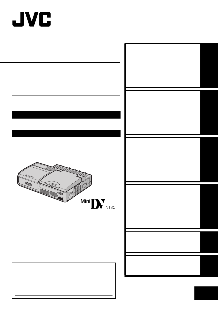
CU-VH1
Please visit our Homepage on the World Wide
Web for Digital Video Camera:
http://www.jvc.co.jp/english/cyber/
For Accessories:
http://www.jvc.co.jp/english/accessory/
ENGLISH
GETTING STARTED 11
VIDEO PLAYBACK
18
INSTRUCTIONS
For Customer Use:
Enter below the Model No. and Serial No. which is
located on the bottom of the player. Retain this
information for future reference.
Model No.
Serial No.
DIGITAL STILL CAMERA
(D.S.C.) PLAYBACK
ADVANCED FEATURES
REFERENCES
TERMS
LYT1221-001A
22
28
44
61
EN
Page 2
2 EN
Dear Customer,
Thank you for purchasing this digital HD player. Before use, please read the safety information and
precautions contained in the following pages to ensure safe use of this product.
Using This Instruction Manual
● All major sections are listed in the Table Of Contents on the cover page.
● Notes appear after most subsections. Be sure to read these as well.
● Basic and advanced features/operation are separated for easier reference.
It is recommended that you…
… refer to the Index (墌 pg. 58 – 60) and familiarize yourself with button locations, etc. before use.
… read thoroughly the Safety Precautions and Safety Instructions that follow. They contain extremely
important information regarding the safe use of this product.
You are recommended to carefully read the cautions on pages 52 through 54 before use.
SAFETY PRECAUTIONS
CAUTION
RISK OF ELECTRIC SHOCK
DO NOT OPEN
CAUTION: TO REDUCE THE RISK OF ELECTRIC SHOCK,
DO NOT REMOVE COVER (OR BACK).
NO USER-SERVICEABLE PARTS INSIDE.
REFER SERVICING TO QUALIFIED SERVICE PERSONNEL.
The lightning flash with arrowhead symbol, within an
equilateral triangle, is intended to alert the user to the
presence of uninsulated "dangerous voltage" within the
product's enclosure that may be of sufficient magnitude
to constitute a risk of electric shock to persons.
The exclamation point within an equilateral triangle is
intended to alert the user to the presence of important
operating and maintenance (servicing) instructions in
the literature accompanying the appliance.
The AA-V40U AC Power Adapter/Charger should
be used with:
AC 120 Vd, 60 Hz in the USA and Canada, AC
110 V - 240 Vd, 50 Hz/60 Hz in other countries.
CAUTION (applies to the AA-V40U)
TO PREVENT ELECTRIC SHOCK MATCH WIDE
BLADE OF PLUG TO WIDE SLOT, FULLY INSERT.
ATTENTION (s’applique à l’AA-V40U)
POUR ÉVITER LES CHOCS ÉLECTRIQUES,
INTRODUIRE LA LAME LA PLUS LARGE DE LA
FICHE DANS LA BORNE CORRESPONDANTE
DE LA PRISE ET POUSSER JUSQU’AU FOND.
NOTES:
● The rating plate (serial number plate) and safety
caution are on the bottom and/or the back of
the main unit.
● The rating plate (serial number plate) of the AC
Power Adapter/Charger is on its bottom.
CAUTIONS:
● This player is designed to be used with NTSCtype color television signals. It cannot be used
for playback with a television of a different
standard. However, LCD monitor playback is
possible anywhere.
● Use the JVC BN-V416U/V428U battery packs
and, to recharge them or supply power to the
player from an AC outlet, use the provided
multi-voltage AC Power Adapter/Charger. (An
appropriate conversion adapter may be
necessary to accommodate different designs of
AC outlets in different countries.)
WARNING:
TO PREVENT FIRE OR SHOCK
HAZARD, DO NOT EXPOSE THIS
UNIT TO RAIN OR MOISTURE.
Page 3
EN 3
When the equipment is installed in a cabinet or on a shelf, make sure that it has sufficient space on all sides
to allow for ventilation (10 cm (3-15/16”) or more on both sides, on top and at the rear).
Do not block the ventilation holes.
(If the ventilation holes are blocked by a newspaper, or cloth etc. the heat may not be able to get out.)
No naked flame sources, such as lighted candles, should be placed on the apparatus.
When discarding batteries, environmental problems must be considered and the local rules or laws
governing the disposal of these batteries must be followed strictly.
The apparatus shall not be exposed to dripping or splashing.
Do not use this equipment in a bathroom or places with water.
Also do not place any containers filled with water or liquids (such as cosmetics or medicines, flower vases,
potted plants, cups etc.) on top of this unit.
(If water or liquid is allowed to enter this equipment, fire or electric shock may be caused.)
This product has a fluorescent lamp that contains a small amount of mercury. Disposal of these materials
may be regulated in your community due to environmental considerations.
For disposal or recycling information please contact your local authorities, or the Electronics Industries
Alliance:
<http://www.eiae.org>
Page 4
4 EN
A
IMPORTANT PRODUCT SAFETY
INSTRUCTIONS
Electrical energy can perform many useful functions.
But improper use can result in potential electrical
shock or fire hazards. This product has been
engineered and manufactured to assure your
personal safety. In order not to defeat the built-in
safeguards, observe the following basic rules for its
installation, use and servicing.
TTENTION:
Follow and obey all warnings and instructions
marked on your product and its operating
instructions. For your safety, please read all the
safety and operating instructions before you operate
this product and keep this manual for future
reference.
INSTALLATION
1. Grounding or Polarization
(A)Your product may be equipped with a polarized
alternating-current line plug (a plug having one
blade wider than the other). This plug will fit into
the power outlet only one way. This is a safety
feature.
If you are unable to insert the plug fully into the
outlet, try reversing the plug. If the plug should
still fail to fit, contact your electrician to replace
your obsolete outlet. Do not defeat the safety
purpose of the polarized plug.
(B) Your product may be equipped with a 3-wire
grounding-type plug, a plug having a third
(grounding) pin. This plug will only fit into a
grounding-type power outlet. This is a safety
feature.
If you are unable to insert the plug into the outlet,
contact your electrician to replace your obsolete
outlet. Do not defeat the safety purpose of the
grounding-type plug.
2. Power Sources
Operate your product only from the type of power
source indicated on the marking label. If you are not
sure of the type of power supply to your home,
consult your product dealer or local power
company. If your product is intended to operate from
battery power, or other sources, refer to the
operating instructions.
3. Overloading
Do not overload wall outlets, extension cords, or
integral convenience receptacles as this can result in
a risk of fire or electric shock.
4. Power Cord Protection
Power supply cords should be routed so that they
are not likely to be walked on or pinched by items
placed upon or against them, paying particular
attention to cords at plugs, convenience receptacles,
and the point where they exit from the product.
5. Ventilation
Slots and openings in the cabinet are provided for
ventilation. To ensure reliable operation of the
product and to protect it from overheating, these
openings must not be blocked or covered.
● Do not block the openings by placing the product
on a bed, sofa, rug or other similar surface.
● Do not place the product in a built-in installation
such as a bookcase or rack unless proper
ventilation is provided or the manufacturer’s
instructions have been adhered to.
6. Wall or Ceiling Mounting
The product should be mounted to a wall or ceiling
only as recommended by the manufacturer.
ANTENNA INSTALLATION INSTRUCTIONS
1. Outdoor Antenna Grounding
If an outside antenna or cable system is connected
to the product, be sure the antenna or cable system
is grounded so as to provide some protection against
voltage surges and built-up static charges. Article
810 of the National Electrical Code, ANSI/NFPA 70,
provides information with regard to proper
grounding of the mast and supporting structure,
grounding of the lead-in wire to an antenna
discharge unit, size of grounding conductors,
location of antenna discharge unit, connection to
grounding electrodes, and requirements for the
grounding electrode.
2. Lightning
For added protection for this product during a
lightning storm, or when it is left unattended and
unused for long periods of time, unplug it from the
wall outlet and disconnect the antenna or cable
system. This will prevent damage to the product due
to lightning and power-line surges.
3. Power Lines
An outside antenna system should not be located in
the vicinity of overhead power lines or other electric
light or power circuits, or where it can fall into such
power lines or circuits. When installing an outside
antenna system, extreme care should be taken to
keep from touching such power lines or circuits as
contact with them might be fatal.
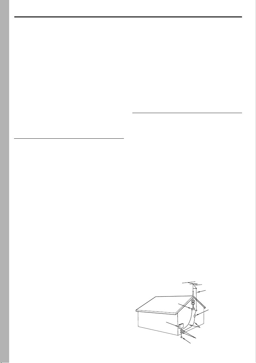
EXAMPLE OF ANTENNA GROUNDING AS PER
NATIONAL ELECTRICAL CODE, ANSI/NFPA 70
ANTENNA
LEAD IN WIRE
GROUND CLAMP
ANTENNA
DISCHARGE UNIT
(NEC SECTION
ELECTRIC SERVICE
EQUIPMENT
POWER SERVICE GROUNDING ELECTRODE SYSTEM
(NEC ART 250. PART H)
NEC – NATIONAL ELECTRICAL CODE
810-20)
GROUNDING CONDUCTORS
(NEC SECTION 810-21)
GROUND CLAMPS
Page 5
EN 5
USE
1. Accessories
To avoid personal injury:
● Do not place this product on an unstable cart,
stand, tripod, bracket or table. It may fall, causing
serious injury to a child or adult, and serious
damage to the product.
● Use only with a cart, stand, tripod, bracket, or
table recommended by the manufacturer or sold
with the product.
● Use a mounting accessory recommended by the
manufacturer and follow the manufacturer’s
instructions for any mounting of the product.
● Do not try to roll a cart with small casters across
thresholds or deep-pile carpets.
2. Product and Cart Combination
A product and cart
combination should be
moved with care. Quick
stops, excessive force, and
uneven surfaces may cause
the product and cart
combination to overturn.
3. Water and Moisture
Do not use this product near
water-for example, near a
bath tub, wash bowl, kitchen sink or laundry tub, in
a wet basement, or near a swimming pool and the
like.
4. Object and Liquid Entry
Never push objects of any kind into this product
through openings as they may touch dangerous
voltage points or short-out parts that could result in a
fire or electric shock. Never spill liquid of any kind
on the product.
5. Attachments
Do not use attachments not recommended by the
manufacturer of this product as they may cause
hazards.
6. Cleaning
Unplug this product from the wall outlet before
cleaning. Do not use liquid cleaners or aerosol
cleaners. Use a damp cloth for cleaning.
7. Heat
The product should be situated away from heat
sources such as radiators, heat registers, stoves, or
other products (including amplifiers) that produce
heat.
PORTABLE CART WARNING
(Symbol provided by RETAC)
SERVICING
1. Servicing
If your product is not operating correctly or exhibits
a marked change in performance and you are
unable to restore normal operation by following the
detailed procedure in its operating instructions, do
not attempt to service it yourself as opening or
removing covers may expose you to dangerous
voltage or other hazards. Refer all servicing to
qualified service personnel.
2. Damage Requiring Service
Unplug this product from the wall outlet and refer
servicing to qualified service personnel under the
following conditions:
a. When the power supply cord or plug is
damaged.
b. If liquid has been spilled, or objects have fallen
into the product.
c. If the product has been exposed to rain or water.
d. If the product does not operate normally by
following the operating instructions. Adjust only
those controls that are covered by the operating
instructions as an improper adjustment of other
controls may result in damage and will often
require extensive work by a qualified technician
to restore the product to its normal operation.
e. If the product has been dropped or damaged in
any way.
f. When the product exhibits a distinct change in
performance-this indicates a need for service.
3. Replacement Parts
When replacement parts are required, be sure the
service technician has used replacement parts
specified by the manufacturer or have the same
characteristics as the original part. Unauthorized
substitutions may result in fire, electric shock or
other hazards.
4. Safety Check
Upon completion of any service or repairs to this
product, ask the service technician to perform safety
checks to determine that the product is in safe
operating condition.
Page 6
6 EN
SAFETY PRECAUTIONS
CAUTION!
The following notes concern possible physical damage to the player and to the user.
When carrying, be sure to always securely attach and use the provided strap. Carrying or holding the player
by the LCD monitor can result in dropping the unit, or in a malfunction.
Take care not to get your finger caught in the cassette holder cover. Do not let children operate the player, as
they are particularly susceptible to this type of injury.
CAUTION!
Connecting cables (S, audio/video, USB, etc.) to the player and leaving it on top of the TV is not
recommended, as tripping on the cables will cause the player to fall, resulting in damage.
䡲 This player is designed exclusively for the digital video cassette, SD Memory Card and MultiMediaCard.
Only cassettes marked “ ” and memory cards marked “ ” or “ ” can be used
with this unit.
Before using the player…
… make sure you only use cassettes with the Mini DV mark .
… make sure you only use memory cards with the mark or .
… remember that this player is not compatible with other digital video formats.
… remember that this player is intended for private consumer use only. Any commercial use without proper
permission is prohibited. (Even if you record an event such as a show, performance or exhibition for
personal enjoyment, it is strongly recommended that you obtain permission beforehand.)
Page 7
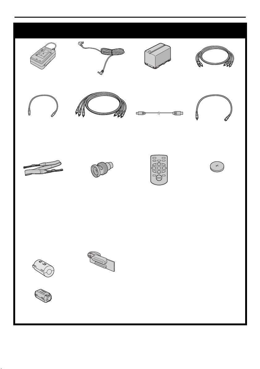
Provided Accessories
EN 7
AC Power Adapter/
Charger AA-V40U
DC Cord Battery Pack
BN-V416U
Audio/Video Cable
(RCA plug to RCA plug)
S-Video Cable Component Video Cable USB Cable Audio Cable x 2
(for connection of
optional headphones
and external microphone
6
0
9
3
4
2
5
we
T
W
Shoulder Strap
(墌 pg. 9 for attachment)
RCA-BNC Adapter x 3 Remote Control Unit
RM-V718U
Lithium Battery CR2025*
(for remote control unit)
* A lithium battery is pre-
installed in the Remote
Control Unit at time of
shipment (with
insulation sheet). To use
the Remote Control
Unit, remove the
insulation sheet.
Core Filter
(墌 pg. 8 for attachment)
墌 pg. 9)
•Large (A) x 2
Connector Cover
•Large (B) x 1
•Medium x 2
•Small x 3
NOTES:
● In order to maintain optimum performance of the player, provided cables may be equipped with one or
more core filter. If a cable has only one core filter, the end that is closest to the filter should be connected to
the player.
● Make sure to use the provided cables for connections. Do not use any other cables.
Page 8
8 EN
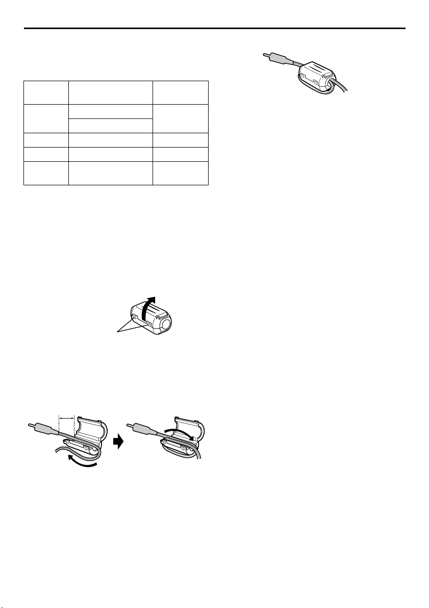
How To Attach The Core Filter
Attach the core filters to the cables. The core filter
reduces interference.
Types of core filters
Size Cable
Large (A)
Large (B) i.LINK cable* Twice
Medium USB cable** Once
Small
* Optional
(If you have an optional JVC i.LINK cable
VC-VDV206U or VC-VDV204U with core
filters, it is not necessary to attach the provided
core filter. If you are going to use any other
i.LINK cable, attach the provided core filter.)
** Attach two core filters to both ends of the cable.
The procedure below is an example of winding
cable once.
Audio/video cable
S-video cable
DC cord
Audio cable
Tim es to
wind
Once
Once
1 Release the stoppers on both ends of the core
filter.
Stopper
2 Run the cable through the core filter, leaving
approx. 3 cm of cable between the cable plug
and the core filter. Wind the cable once around
the outside of the core filter as shown in the
illustration.
● Wind the cable so that it is not slack.
3 cm
3 Close the core filter until it clicks shut.
NOTES:
● Take care not to damage the cable.
● When connecting a cable, attach the end with the
core filter to the player.
Wind once.
Page 9
EN 9
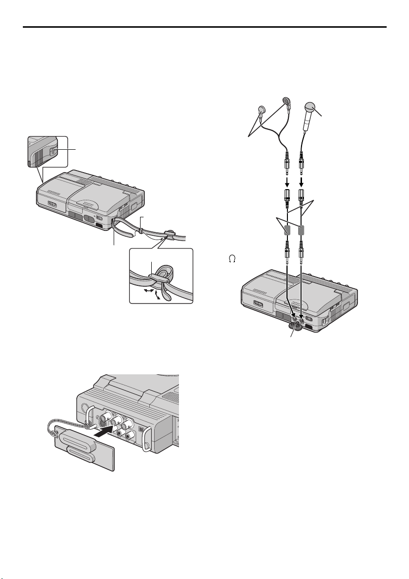
How To Attach The Strap
1 Thread the strap through the eyelet a.
2 Fold it back and thread it through the strap guide
and the buckle.
● To adjust the length of the strap, loosen and
then tighten the strap in the buckle.
3 Repeat the procedure to attach the other end of
the strap to the other eyelet b.
4 Confirm the strap is not twisted.
Eyelet b
Strap guide
Eyelet a
Buckle
How To Use The Audio Cable
When using optional headphones or external
microphone, connect to the provided audio cable
(with a core filter attached), then connect the audio
cable to the player. The core filter reduces
interference.
Microphone
Headphones
Audio cable
Core filter
To (headphones)
(provided)
To MI C
How To Attach The Connector
Cover
To protect the connectors, attach the provided
connector cover to the rear panel of the player when
the player is not in use.
Open the connector cover.
Page 10

10 EN
CONTENTS
GETTING STARTED 11
Power .......................................................................11
Operation Mode .......................................................13
LCD Monitor ............................................................14
Brightness Adjustment Of The Display ......................14
Date/Time Settings ....................................................15
Loading A Cassette
/Unloading A Cassette ..........................................16
Loading A Memory Card
/Unloading A Memory Card .................................17
VIDEO PLAYBACK 18
Normal Playback ......................................................18
Still Playback ............................................................18
Frame-By-Frame Playback ........................................18
Shuttle Search ...........................................................19
Blank Search ............................................................19
Connections To A TV Or VCR ..................................20
DIGITAL STILL CAMERA (D.S.C.) PLAYBACK 22
Normal Playback Of Images .....................................22
Auto Playback Of Images .........................................22
Index Playback Of Files ............................................23
Viewing File Information ..........................................23
Removing On-Screen Display ...................................23
Protecting Files .........................................................24
Deleting Files ...........................................................25
Resetting The File Name ...........................................26
Setting Print Information (DPOF Setting) ...................26
Initializing A Memory Card ......................................27
ADVANCED FEATURES 28
MENUS FOR DETAILED ADJUSTMENT ...........................28
Changing The Menu Settings ....................................28
PLAYBACK MENUS .....................................................29
NAVIGATION............................................................. 32
NAVIGATION Function ...........................................32
DUBBING ..................................................................34
Dubbing To Or From A VCR ....................................34
Dubbing To Or From A Video Unit Equipped With
An i.LINK Connector (Digital Dubbing) ................35
Recording From The Middle Of A Tape ....................36
Dubbing Still Images Recorded On A Tape To
A Memory Card ....................................................38
USING THE REMOTE CONTROL UNIT ...........................39
Audio Dubbing (DV mode only) ...............................42
SYSTEM CONNECTIONS ..............................................43
Connection To A Personal Computer ........................43
REFERENCES 44
DETAILS ....................................................................44
TROUBLESHOOTING ................................................... 45
CAUTIONS ................................................................. 52
USER MAINTENANCE .................................................. 55
SPECIFICATIONS ........................................................ 56
INDEX .......................................................................58
TERMS 61
Page 11
EN 11
A
Power
This player’s 2-way power supply system lets you
choose the most appropriate source of power. Do
not use provided power supply units with other
equipment.
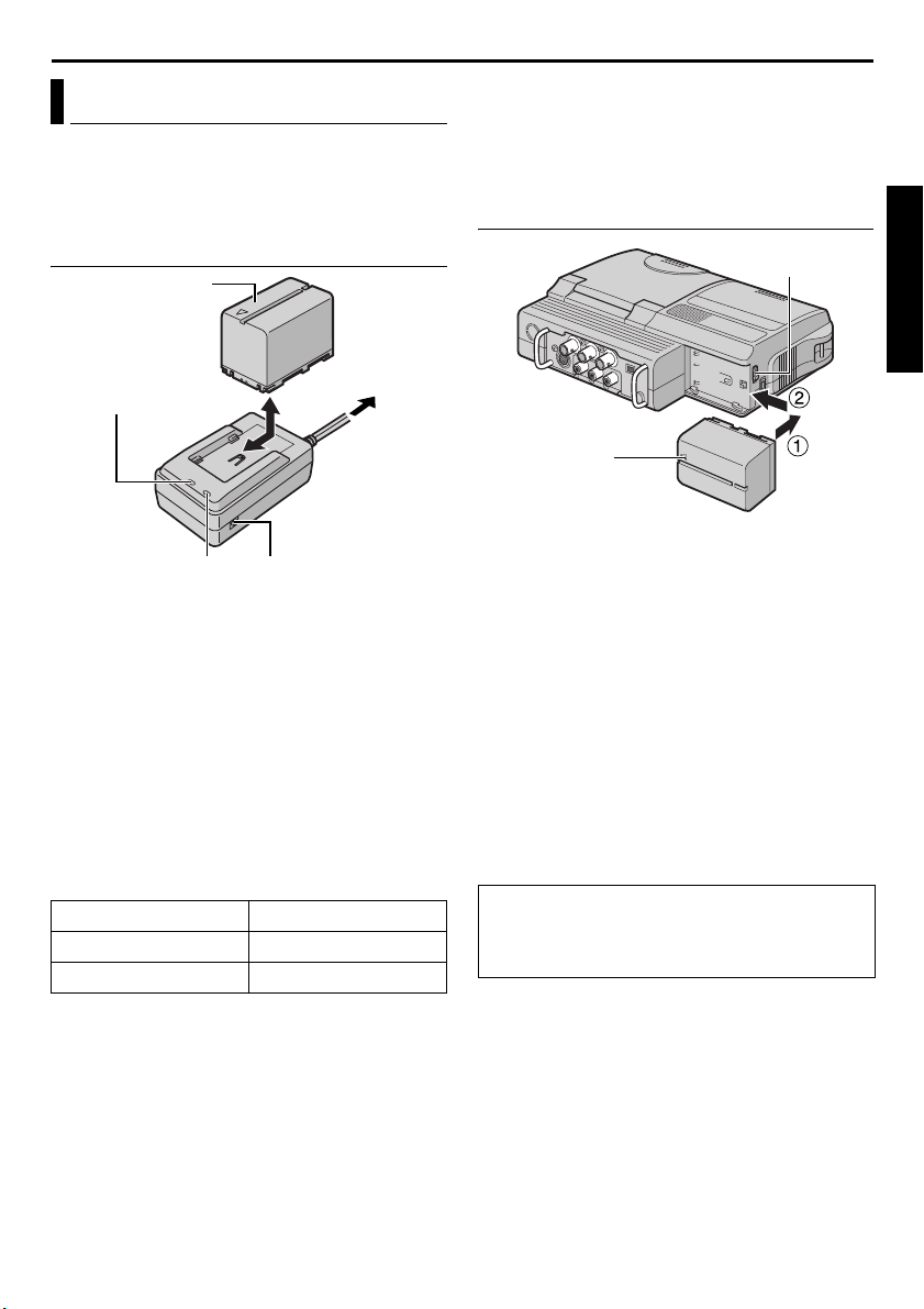
Charging The Battery Pack
Battery pack
BN-V416U or
BN-V428U
POWER indicator
AC Power Adapter/
Charger
CHARGE indicator
Make sure you unplug the player’s DC cord from
1
the AC Power Adapter/Charger.
2 Plug the AC Power Adapter/Charger’s power cord
into an AC outlet. The POWER indicator lights.
3 Attach the battery pack with the YZ mark
aligned with the corresponding marks on the AC
Power Adapter/Charger. The CHARGE indicator
begins blinking to indicate charging has started.
4 When the CHARGE indicator stops blinking but
stays lit, charging is finished. Remove the battery
pack.
5 Unplug the AC Power Adapter/Charger’s power
cord from the AC outlet.
Battery pack Charging time
BN-V416U* Approx. 2 hr.
BN-V428U Approx. 3 hr. 20 min.
*Provided
NOTES:
● If the protective cap is attached to the battery
pack, remove it first.
● If you connect the player’s DC cord to the AC
Power Adapter/Charger during battery charging,
power is supplied to the player and charging stops.
● Charging is not possible if the wrong type of
battery is used.
● When charging the battery pack for the first time
or after a long storage period, the CHARGE
indicator may not light. In this case, remove the
battery pack from the AC Power Adapter/Charger,
then try charging again.
DC OUT connector
To AC o utl et
● If the battery operation time remains extremely
short even after having been fully charged, the
battery is worn out and needs to be replaced.
Please purchase a new one.
● For other notes, 墌 pg. 44.
Using The Battery Pack
BATT.RELEASE
Switch
Arrow
With the arrow on the battery pack pointing to
1
the left, push the battery pack slightly against the
battery pack mount a.
2 Slide the battery pack to the left until it locks in
place b.
To detach the battery pack...
Slide the battery pack to the right slightly while
sliding BATT. RELEASE to detach it.
NOTES:
● Available time is reduced significantly under the
following conditions:
• The LCD monitor is used repeatedly.
• The playback mode is engaged repeatedly.
● Before extended use, it is recommended that you
prepare enough battery packs to cover 3 times the
planned recording time.
TTENTION:
Before detaching the power source, make sure
that the player’s power is turned off. Failure to do
so can result in a player malfunction.
CONTINUED ON NEXT PAGE
GETTING STARTED
Page 12
12 EN
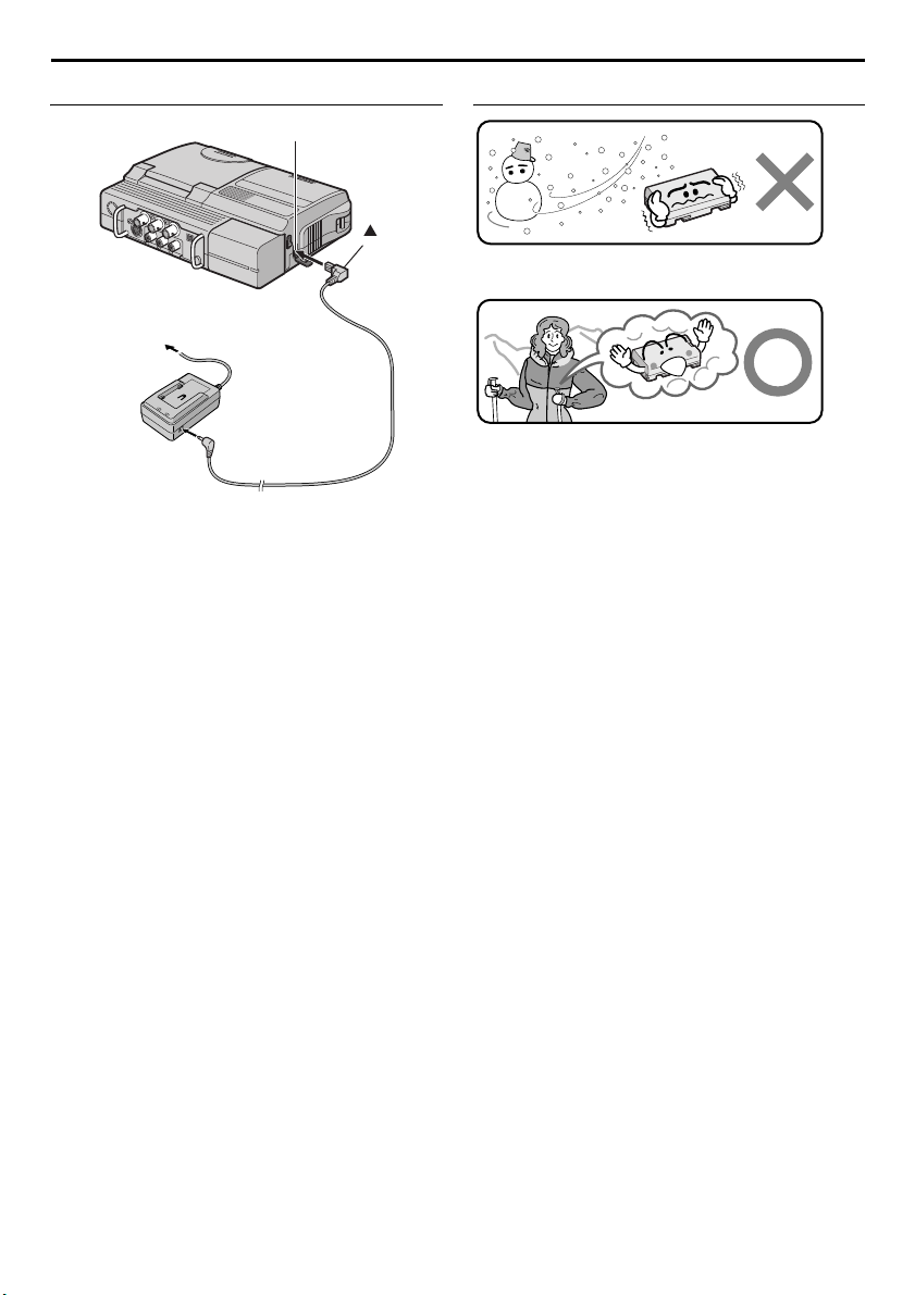
Using AC Power
Open the cover.
Mark
To DC connector
To AC outlet
Power cord
AC Power Adapter/
Charger
To DC O U T
connector
DC cord
Make sure you unplug the player’s DC cord from
1
the AC Power Adapter/Charger.
2 Connect the AC Power Adapter/Charger to the
player as shown in the illustration above.
NOTES:
● The provided AC Power Adapter/Charger features
automatic voltage selection in the AC range from
110 V to 240 V.
● For other notes, 墌 pg. 44.
About Batteries
Lithium-ion is vulnerable in colder temperatures.
DANGER! Do not attempt to take the batteries apart,
or expose them to flame or excessive heat, as it may
cause a fire or explosion.
WARNING! Do not allow the battery or its terminals
to come in contact with metals, as this can result in
a short circuit and possibly start a fire.
The Benefits Of Lithium-Ion Batteries
Lithium-ion battery packs are small but have a large
power capacity. However, when one is exposed to
cold temperatures (below 10°C/50°F), its usage time
becomes shorter and it may cease to function. If this
happens, place the battery pack in your pocket or
other warm, protected place for a short time, then
re-attach it to the player. As long as the battery pack
itself is not cold, it should not affect performance.
(If you’re using a heating pad, make sure the battery
pack does not come in direct contact with it.)
For other notes, 墌 pg. 44.
Page 13
EN 13
Operation Mode
To turn on the player, set the Power Switch to “ON”
while pressing down the Lock Button located on the
switch.
Video Output Mode
Power Switch
Choose the appropriate operation mode according
to your preference using Playback Mode Switch for
playback and Video Output Mode Switch for signal
output.
ON:
Allows you to switch on the player.
OFF:
Allows you to switch off the player.
Switch
Playback Mode Switch
Lock Button
Power Switch Position
Playback Mode Switch Position
VIDEO:
Allows you to play back a tape.
MEMORY:
Allows you to play back images stored in a
memory card or access data stored in a memory
card.
Video Output Mode Switch Position
COMPONENT VIDEO OUT:
Allows you to output signals from the Component
Video connector. When you view images on the
connected TV, set the switch to this mode.
(墌 pg. 20)
LCD MONITOR:
When you view images on the player’s LCD
monitor or TV connected via video or S-video
cable, set the switch to this mode.
GETTING STARTED
Page 14
14 EN
BR IGHT
LCD Monitor
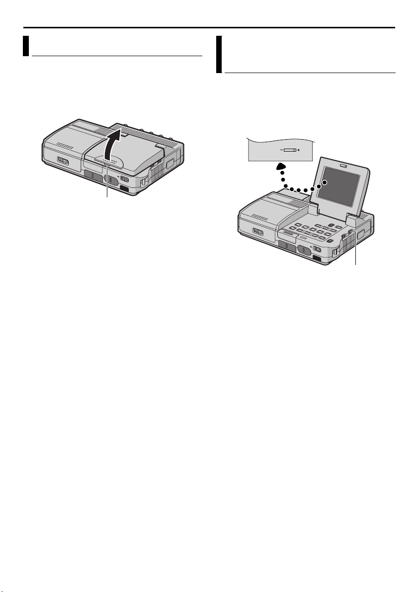
Press the Monitor Opening Button and open the
LCD monitor fully.
To view images on the LCD monitor, set the Video
Output Mode Switch to “LCD MONITOR”.
(墌 pg. 13)
Monitor Opening Button
NOTES:
● The image on the LCD monitor and the image on
the TV screen may look differently in terms of the
brightness and color. Confirm the final image on
the TV screen.
● Colored bright spots may appear all over the LCD
monitor. However, this is not a malfunction.
(墌 pg. 47)
Brightness Adjustment Of The Display
1 Set the Power Switch to “ON” while pressing
down the Lock Button located on the switch.
2 Open the LCD monitor fully.
3 Rotate the BRIGHT Wheel until the appropriate
brightness is reached.
BRIGHT Wheel
Page 15
EN 15
Date/Time Settings
The date/time display can be turned on or off during
playback. (墌 pg. 28, 31)
R T Button
MENU Button
Power Sw itc h
1 Set the Power Switch to “ON” while pressing
down the Lock Button located on the switch.
2 Open the LCD monitor fully.
3 Press MENU. The Menu
Screen appears.
4 Press R or T to select
“n” (DISPLAY), and press
MENU. The DISPLAY
Menu appears.
5 Press R or T to select
“CLOCK ADJ.”, and press
MENU. The parameter for
“Month” is highlighted.
6 Press R or T to input the
month, and press MENU.
Repeat to input the day,
year, hour and minute.
7 Press R or T to select
“BRETURN”, and press
MENU twice. The Menu
Screen closes.
CL C 2
AD . 3:5
ST RE–EO
DU
DMSO N EO
L.V.DENA I
NRETUR
A
SERA CM I
D
NCREON S E
D
J AD .
NRETUR
OK
J
NRETUR
ID O V E
LA
Y IS L D P
LC –
OFMET–/TI DA E F
OFDEM– CO TI E
DE OK CL C 2 C
YIS LDPA
DEC
OF. –ARR DV N F
E C–MO D RE
ONCO Y P –
OFPUA IN S/ V T F–
YP
A
F
3:5
5'0 3
5'0 3
0 PM
0 PM
GETTING STARTED
Page 16
16 EN
Loading A Cassette /Unloading A Cassette
The player needs to be powered up to load or eject a
cassette
Cassette holder
OPEN/EJECT
Cassette
holder
Make sure the
window side is
facing up.
1 Slide and hold OPEN/EJECT in the direction of
arrow, then pull the cassette holder cover open
until it locks. The cassette holder opens
automatically.
● Do not touch internal components.
2 Insert or remove a tape and press “PUSH HERE”
to close the cassette holder.
● Be sure to press only the section labeled
“PUSH HERE” to close the cassette holder;
touching other parts may cause your finger to
get caught in the cassette holder, resulting in
injury or product damage.
● Once the cassette holder is closed, it recedes
automatically. Wait until it recedes completely
before closing the cassette holder cover.
● When the battery pack’s charge is low, you may
not be able to close the cassette holder cover.
Do not apply force. Replace the battery pack
with a fully charged one or use AC power
before continuing.
3 Close the cassette holder cover firmly until it
locks into place.
To protect valuable recordings…
Slide the erase protection tab on the back of the tape
in the direction of “SAVE”. This prevents the tape
from being recorded over. To record on this tape,
slide the tab back to “REC” before loading it.
cover
Switch
Erase protection tab
PUSH HERE
Approximate recording time
Ta pe
30 min. 30 min. 45 min.
60 min. 60 min. 90 min.
80 min. 80 min. 120 min.
To switch the recording mode, refer to pages 28 and
29.
NOTES:
● It takes a few seconds for the cassette holder to
open. Do not apply force.
● If you wait a few seconds and the cassette holder
does not open, close the cassette holder cover and
try again. If the cassette holder still does not open,
turn the player off then on again.
● If the tape does not load properly, open the
cassette holder cover fully and remove the
cassette. A few minutes later, insert it again.
● When the player is suddenly moved from a cold
place to a warm environment, wait a short time
before opening the cassette holder cover.
● Closing the cassette holder cover before the
cassette holder recedes may cause damage to the
player.
● Even when the player is switched off, a cassette
can be loaded or unloaded. After the cassette
holder is closed with the player switched off,
however, it may not recede. It is recommended to
turn the power on before loading or unloading.
● When resuming recording, once you open the
cassette holder cover a blank portion will be
recorded on the tape or a previously recorded
scene will be erased (recorded over) regardless of
whether the cassette holder came out or not. See
“Recording From The Middle Of A Tape”
(墌 pg. 36).
Recording mode
SP LP
Page 17
EN 17
A
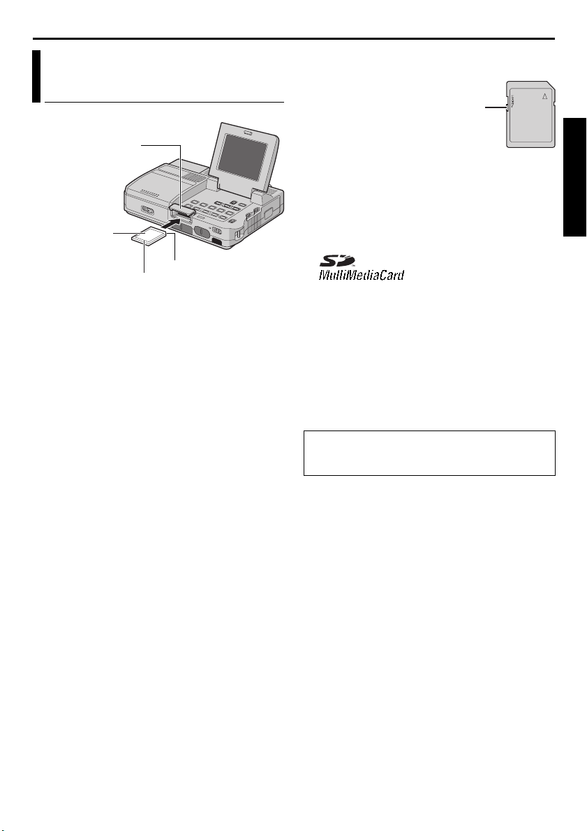
Loading A Memory Card /Unloading A Memory Card
Card Cover
(MEMORY CARD)
Memory card
Clipped edge
Label
1 Make sure the player’s power is off.
2 Slide to open the card cover (MEMORY CARD).
3 To load a memory card, firmly insert it with its
clipped edge first.
To unload a memory card, push it once. After the
memory card comes out of the player, pull it out.
● Do not touch the terminal on the reverse side
of the label.
4 Close the card cover.
To protect valuable files (available only for SD
Memory Card)…
Write/erase protection tab
Slide the write/erase protection tab on the side of the
memory card in the direction of “LOCK”. This
prevents the memory card from being recorded over.
To record on this memory card, slide the tab back to
the position opposite to “LOCK” before loading it.
NOTES:
● Be sure to use only SD Memory Cards marked
“ ” or MultiMediaCards marked
“”.
● Some brands of memory cards are not compatible
with this player. Before purchasing a memory
card, consult its manufacturer or dealer.
● Before using a new memory card, it is necessary to
FORMAT the card. (墌 pg. 27)
TTENTION:
Do not insert or remove the memory card while the
player is turned on, as this may cause the memory
card to be corrupted or cause the player to become
unable to recognize whether or not the card is
installed.
Information On SD Memory Card
SD Memory Cards up to 64 MB have been verified
for use with this player. (As of October 2003)
GETTING STARTED
Page 18
18 EN
VIDEO PLAYBACK
Normal Playback
Fast-Forward Button (5)
Play/Pause Button (4/9)
Rewind Button (3)
Stop Button (8)
Speaker
Power Switch
1 Open the LCD monitor fully.
VIDEO PLAYBACK
● Set the Video Output Mode Switch to “LCD
MONITOR”. (墌 pg. 13)
2 Load a cassette. (墌 pg. 16)
3 Set the Playback Mode Switch to “VIDEO”.
4 Set the Power Switch to “ON” while pressing
down the Lock Button located on the switch.
5 To start playback, press 4/9.
6 To stop playback, press 8.
● During Stop mode, press 3 to rewind, or
5 to fast-forward the tape.
Maximum continuous playback time
Battery pack DV mode HD/SD mode
BN-V416U* 1 hr. 40 min. 1 hr. 30 min.
BN-V428U 3 hr. 2 hr. 50 min.
*Provided
BLANK SEARCH
VOLUME Wheel
Playback Mode
Switch
Button
NOTES:
● Clean the video heads using an optional dry
cleaning cassette when:
• No picture during playback.
• Blocks of noise appear during playback.
For details, 墌 pg. 53.
● If Stop mode continues for 5 minutes when power
is supplied from a battery, the player shuts off
automatically. To turn on again, set the Power
Switch to “OFF”, then “ON”.
● The playback picture can be viewed in the LCD
monitor or on a connected TV. (墌 pg. 20)
● LCD monitor indications:
• When power is supplied from a battery: the
“ ” battery indicator is displayed. (墌 pg. 49)
• When power is supplied from an AC outlet: the
“ ” battery indicator does not appear.
● When a cable is connected to the S2, AUDIO (L/
R), VIDEO or headphone connector, sound cannot
be heard from the speaker.
To control the speaker volume…
Rotate the VOLUME Wheel towards “+” to turn up
the volume, or towards “–” to turn down the
volume.
Still Playback
Pauses during video playback.
1) Press 4/9 during playback.
2) To resume normal playback, press 4/9 again.
● If still playback continues for more than about
3 minutes, the player’s Stop mode is
automatically engaged.
● When 4/9 is pressed, the image may not
pause immediately while the player stabilizes
the still image.
Frame-By-Frame Playback
Allows frame-by-frame search during video
playback. This feature is available only with a tape
recorded in DV recording mode.
1) Press 4/9 during playback.
2) Press R for forward and T for reverse.
Page 19
EN 19
A
Shuttle Search
Allows high-speed search in either direction during
video playback.
1) During playback, press 5 for forward search,
or 3 for reverse search.
2) To resume normal playback, press 4/9.
● During playback, press and hold 5 or 3.
The search continues as long as you hold the
button. Once you release the button, normal
playback resumes.
● A slight mosaic effect appears on the display
during Shuttle Search. This is not a
malfunction.
TTENTION:
(DV mode only)
During Shuttle Search, parts of
the picture may not be clearly
visible, particularly on the left
side of the screen.
Blank Search
Helps you find where you should start recording in
the middle of a tape to avoid time code interruption.
(墌 pg. 36)
1 Load a cassette. (墌 pg. 16)
2 Set the Playback Mode Switch to “VIDEO”.
3 During Stop mode,
press BLANK
SEARCH.
● The “BLANK
SEARCH”
indication appears
and the player
automatically starts
reverse or forward search, then stops at the
spot which is about 3 seconds of tape before
the beginning of the detected blank portion.
● To cancel Blank Search midway, press 8.
BLANK SEARCH
PUSH "STOP" BUTTON
TO CANCEL
NOTES:
● Before starting Blank Search, if the current position
is at a blank portion, the player searches in the
reverse direction. If the current position is at a
recorded portion, the player searches in the
forward direction.
● Blank Search does not work if “USE CLEANING
CASSETTE” has appeared with the tape.
● If the beginning or end of the tape is reached
during Blank Search, the player stops
automatically.
● A blank portion which is shorter than 5 seconds of
tape may not be detected.
● The detected blank portion may be located
between recorded scenes. Before you start
recording, make sure there is no recorded scene
after the blank portion.
Slow-Motion Playback
Playback Zoom
Available only with the remote control (provided).
(墌 pg. 40, 41)
VIDEO PLAYBACK
Page 20
20 EN
VIDEO PLAYBACK (cont.)
Connections To A TV Or VCR
These are some basic types of connections. When
making the connections, refer also to your VCR and
TV instruction manuals.
To Connect A Conventional TV or VCR
COMPONENT
COMPONENT
YY
S2S2
PbPb PrPr
VIDEOVIDEO AUDIOAUDIOLLRR
Audio/Video cable
(provided)
To AUDIO/
VIDEO
VIDEO
VIDEO
OUT
OUT
To S2
S-Video cable
(provided)
To Connect To A TV or VCR Equipped With The
Component Video Connectors
To Y/ P b /Pr
RCA-BNC
Adapter
COMPONENT
COMPONENT
YY
S2S2
cable
PbPb PrPr
VIDEOVIDEO AUDIOAUDIOLLRR
A
To AUDIO
Component video cable
(provided)
VIDEO
VIDEO
OUT
OUT
Audio/Video
(provided)
BCD
A
VCR
A To S- V I D EO IN*
B Yellow to VIDEO IN**
C White to AUDIO L IN***
D Red to AUDIO R IN***
TV
* Connect when your TV/VCR has S-VIDEO IN
and A/V input connectors. In this case, it is not
necessary to connect the yellow video cable.
** Connect when your TV/VCR has only A/V input
connectors.
*** Not required for watching still images only.
A
CB
D
Wide-screen TV or
high definition TV
VCR
A Not required for connection.
B White to AUDIO L IN*
C Red to AUDIO R IN*
D To component video connectors
* Not required for watching still images only.
Page 21

EN 21
1 Make sure all units are turned off.
2 Connect the player to a TV or VCR as shown in
the illustration.
If using a VCR, go to step 3.
If not, go to step 4.
3 Connect the VCR output to the TV input,
referring to your VCR’s instruction manual.
4 For S-video or video connection
Set “S/VIDEO” to “16:9 TV” or “4:3 TV”
depending on the aspect ratio of the TV you are
connecting. (墌 pg. 28, 30)
● Set the Video Output Mode Switch to “LCD
MONITOR”.
For component video connection
● Set “Y/Pb/Pr” to any picture size depending on
the TV to which you are connecting.
(墌 pg. 28, 30)
● Set the Video Output Mode Switch to
“COMPONENT VIDEO OUT”.
5 Turn on the VCR and the TV.
6 Set the VCR to its AUX input mode, and set the
TV to appropriate input mode.
To choose whether or not the following displays
appear on the connected TV…
● Date/Time
Set “DATE/TIME” to “AUTO”, “ON” or “OFF”.
(墌 pg. 28, 31)
Or, press DISPLAY on the remote control to turn
on/off the date indication.
● Time Code
Set “TIME CODE” to “ON” or “OFF”.
(墌 pg. 28, 31)
● Indications other than date/time and time code
Set “ON SCREEN” to “OFF”, “LCD” or “LCD/TV”.
(墌 pg. 28, 31)
NOTES:
● It is recommended to use the AC Power Adapter/
Charger as the power supply instead of the
battery pack. (墌 pg. 12)
● Make sure you adjust the TV sound volume to its
minimum level to avoid a sudden burst of sound
when the player is turned on.
● If you have a TV or speakers that are not specially
shielded, do not place the speakers adjacent to the
TV as interference will occur in the player
playback picture.
● During playback in HD mode, the images may not
appear on the player’s LCD monitor if the
component video cable is connected.
● When a cable is connected to the S2, AUDIO (L/
R), VIDEO or headphone connector, sound cannot
be heard from the speaker.
● According to the type of the connected TV and the
recording mode, the playback picture may be
squeezed vertically or horizontally. For details,
refer to the Instructions of the TV.
VIDEO PLAYBACK
Page 22

22 EN
DIGITAL STILL CAMERA (D.S.C.) PLAYBACK
Normal Playback Of Images
You can view the stored images in the memory card,
one at a time, much like flipping through a photo
album.
Fast-Forward Button (5)
Play/Pause Button (4/9)
Rewind Button (3)
Stop Button (8)
INDEX Button
INFO Button
Power Switch
1 Open the LCD monitor fully.
● Set the Video Output Mode Switch to “LCD
MONITOR”. (墌 pg. 13)
2 Load a memory card. (墌 pg. 17)
3 Set the Playback Mode Switch to “MEMORY”.
4 Set the Power Switch to “ON” while pressing
down the Lock Button located on the switch.
● The still image which has been played back at
the last time is displayed.
5 Press 3 to display the previous file. Press 5
to display the next file.
● Pressing INFO gives you details on the
displayed file. (墌 pg. 23)
● You can also look for the desired file using
Index Screen. (墌 pg. 23)
● You can turn off the on-screen playback
display. (墌 pg. 23)
MENU Button/
R T Button
Playback Mode
Switch
D.S.C. PLAYBACK
NOTES:
● Images shot in a file size other than “640 x 480”,
“848 x 480”, “1280 x 720” and “1280 x 960”
with another devices will be displayed thumbnail
images. These thumbnail images cannot be
transferred to a PC.
● Images shot with devices (such as JVC GRDVM70) that are not compatible with DCF cannot
be viewed with this player; “UNSUPPORTED
FILE!” will be displayed.
Playback Zoom
Available only with the remote control (provided).
(墌 pg. 41)
Auto Playback Of Images
You can run through all the images stored in
memory card automatically.
1 Perform steps 1 – 4 in “Normal Playback Of
Images”.
2 Press 4/9 to start Auto Playback. Files are
displayed in descending order.
● If you press 3 during Auto Playback, files
are displayed in ascending order.
3 To end Auto Playback, press 8.
[For Normal Playback]
To display the next image
Image playback screen
[For Auto Playback]
100-0013
100-0014
100-0015
To display the previous image
100-0016
Page 23

EN 23
Index Playback Of Files
You can view several different files stored in the
memory card at a time. This browsing capability
makes it easy to locate a particular file you want.
1 Perform steps 1 – 4 in “Normal Playback Of
Images” (墌 pg. 22).
2 Press INDEX. The Index Screen of the image files
appears.
Selected file
Index number
Index Screen
3
2
1
4
5
6
8 9
7
3 Press R or T to move the frame to the desired
file.
● Press 3 to display the previous page. Press
5 to display the next page.
4 Press MENU. The selected file is displayed.
● Pressing INFO gives you details on the
displayed file. (See below.)
Viewing File Information
You can get the relevant file information by pressing
the INFO Button during normal playback or Index
Playback.
FOLDER : Folder name (墌 pg. 26)
FILE : File name (墌 pg. 26)
DATE : Date the file was made
SIZE : Image size
QUALITY : Picture quality
PROTECT : When set to “ON”, the file is
protected from accidental erasure.
(墌 pg. 24)
F
O
L
D
E
R
:
1
0
0
J
V
C
F
I
L
E
D
A
T
E
S
I
Z
E
Q
U
A
L
P
R
O
T
G
:
D
V
C
0
0
0
1
OCT 0
3
:
:
1
2
8
0
X
7
2
I
T
Y
:
F
I
N
E
E
C
T
:
O
F
F
R
0
3
0
0
Information Screen
● Press the INFO Button again to close the
Information Screen.
NOTE:
With images shot with other devices or processed on
a PC, “QUALITY: – – –” will be displayed.
Removing On-Screen Display
1 Perform steps 1 – 4 in “Normal Playback Of
Images” (墌 pg. 22).
2 Press MENU. The Menu Screen appears.
3 Press R or T to select “DISPLAY”, and press
MENU. The Sub Menu appears.
4 Press R or T to select “OFF”, and press MENU.
The operation mode indicator, folder/file number
and battery indicator ( ) disappear.
● To display the indicators again, select “ON”.
Operation mode indicator
Folder/file number
100-0013
DISPLAYM E NU
OFF
ON
RETURN
Battery indicator
DIGITAL STILL CAMERA (D.S.C.) PLAYBACK
Page 24

24 EN
D.S.C. PLAYBACK (cont.)
Protecting Files
The Protect mode helps prevent the accidental
erasure of files.
RT Button
MENU Button
Rewind Button (3)
Power Switch
Fast-Forward Button (5)
1 Open the LCD monitor fully.
● Set the Video Output Mode Switch to “LCD
MONITOR”. (墌 pg. 13)
2 Load a memory card. (墌 pg. 17)
3 Set the Playback Mode Switch to “MEMORY”.
4 Set the Power Switch to “ON” while pressing
down the Lock Button located on the switch.
● The still image which has been played back at
the last time is displayed.
5 Press MENU. The Menu Screen appears.
6 Press R or T to select
“PROTECT”, and press
MENU. The Sub Menu
appears.
Playback Mode
Switch
MENU
PROTECT
DELE TE
DPOF
NO . RESE T
FORMAT
DISPLAY
END
To protect the currently displayed file
7 Press R or T to select
“CURRENT”, and press
MENU. The PROTECT
screen appears.
8 Press 3 or 5 to
select the desired file.
9 Press R or T to select
“EXECUTE”, and press
MENU.
● To cancel protection,
select “RETURN”.
● Repeat steps 8 and 9 for
all files you want to
protect.
To protect all files stored in the memory
card
CUR
PROTECTM E NURENT
PROT.ALL
CANC.ALL
RETURN
ROT ECTP
PROTECTED
RETURN
7 Press R or T to select “PROT.ALL”, and press
MENU. The PROTECT screen appears.
8 Press R or T to select “EXECUTE”, and press
MENU.
● To cancel protection, select “RETURN”.
NOTES:
● If the “ ” mark appears, the currently displayed
file is protected.
● When the memory card is initialized or corrupted,
even protected files are deleted. If you do not want
to lose important files, transfer them to a PC and
save them.
To Remove Protection
Before doing the following, perform steps 1 – 6 in
“Protecting Files” in the left column.
To remove protection from the currently
displayed file
7 Press R or T to select “CURRENT”, and press
MENU. The PROTECT screen appears.
8 Press 3 or 5 to select the desired file.
9 Press R or T to select “EXECUTE”, and press
MENU.
● To cancel selection, select “RETURN”.
● Repeat steps 8 and 9 for all files you want to
remove protection.
Page 25

EN 25
To remove protection from all files stored
in the memory card
7 Press R or T to select “CANC.ALL”, and press
MENU. The PROTECT screen appears.
8 Press R or T to select “EXECUTE”, and press
MENU.
● To cancel selection, select “RETURN”.
Deleting Files
Previously stored files can be deleted either one at a
time or all at once.
RT Button
MENU Button
Rewind Button (3)
Power Switch
Fast-Forward Button (5)
1 Open the LCD monitor fully.
● Set the Video Output Mode Switch to “LCD
MONITOR”. (墌 pg. 13)
2 Load a memory card. (墌 pg. 17)
3 Set the Playback Mode Switch to “MEMORY”.
4 Set the Power Switch to “ON” while pressing
down the Lock Button located on the switch.
● The still image which has been played back at
the last time is displayed.
5 Press MENU. The Menu Screen appears.
6 Press R or T to select “DELETE”, and press
MENU. The Sub Menu appears.
Playback Mode
Switch
To delete the currently displayed file
7 Press R or T to select
“CURRENT”, and press
MENU. The DELETE
screen appears.
DELE TE M E NURENT
CUR
ALL
RET URN
8 Press 3 or 5 to
select the desired file.
9 Press R or T to select
“EXECUTE”, and press
MENU.
● To cancel deletion,
select “RETURN”.
● Repeat steps 8 and 9 for
all files you want to
delete.
NOTE:
If the “ ” mark appears, the selected file is
protected and cannot be deleted.
ELETED
DELE TE?
EXECUTE
RETURN
To delete all files stored in the memory
card
7 Press R or T to select “ALL”, and press MENU.
The DELETE screen appears.
8 Press R or T to select “EXECUTE”, and press
MENU.
● To cancel deletion, select “RETURN”.
NOTES:
● Protected files (墌 pg. 24) cannot be deleted. To
delete them, remove protection first.
● Once files are deleted, they cannot be restored.
Check files before deleting.
CAUTION:
Do not remove the memory card or perform any
other operation (such as turning off the player)
during deletion. Also, be sure to use the provided
AC Power Adapter/Charger, as the memory card
may be corrupted if the battery becomes
exhausted during deletion. If the memory card
becomes corrupted, initialize it. (墌 pg. 27)
DIGITAL STILL CAMERA (D.S.C.) PLAYBACK
Page 26

26 EN
D.S.C. PLAYBACK (cont.)
Resetting The File Name Setting Print Information (DPOF
By resetting the file name, a new folder will be
made. The new files you are going to make will be
stored in the new folder. It is convenient to separate
the new files from previously made files.
1 Open the LCD monitor fully.
● Set the Video Output Mode Switch to “LCD
MONITOR”. (墌 pg. 13)
2 Load a memory card. (墌 pg. 17)
3 Set the Playback Mode Switch to “MEMORY”.
4 Set the Power Switch to “ON” while pressing
down the Lock Button located on the switch.
● The still image which has been played back at
the last time is displayed.
5 Press MENU. The Menu Screen appears.
6 Press R or T to select “NO. RESET”, and press
MENU. The NO. RESET screen appears.
7 Press R or T to select “EXECUTE”, and press
MENU. The new folder (such as “101JVCGR”)
will be made and the file made of the next shot
starts from DVC00001.
Folder and File names
Each time you dub still images recorded on a tape to
a memory card, a file name is made using a number
which is larger by one than the largest number of the
file names which are in use. Even if you delete an
image file with a number in the middle of range, the
number will not be used for a new shot; a gap will
remain in the numerical sequence. If the file name
reaches DVC09999, a new folder (such as
“101JVCGR”) will be made and the file name will
start again from DVC00001.
Setting)
This player is compatible with the DPOF (Digital
Print Order Format) standard in order to support
future systems such as automatic printing. You can
select one of the 2 print information settings for
images stored in the memory card: “To Print All Still
Images (One Print For Each)” or “To Print By
Selecting Still Images And Number Of Prints”.
NOTES:
● If you load a memory card already set as shown
below in a printer compatible with DPOF, it will
make prints of the selected still images
automatically.
● To print images recorded on a tape, first dub them
to a memory card. (墌 pg. 38)
To Print All Still Images (One Print For Each)
1
Open the LCD monitor fully.
● Set the Video Output Mode Switch to “LCD
MONITOR”. (墌 pg. 13)
2 Load a memory card. (墌 pg. 17)
3 Set the Playback Mode Switch to “MEMORY”.
4 Set the Power Switch to “ON” while pressing
down the Lock Button located on the switch.
● The still image which has been played back at
the last time is displayed.
5 Press MENU. The Menu Screen appears.
6 Press R or T to select
“DPOF”, and press
MENU. The Sub Menu
appears.
7 Press R or T to select
“ALL 1”, and press MENU.
The DPOF screen appears.
8 Press R or T to select
“EXECUTE”, and press
MENU. The normal
playback screen appears.
● To cancel selection,
select “RETURN”.
DPOF M E NURENT
CUR
ALL 1
RESET
RETURN
DPOF
ALL1 ?
EXECUTE
RETURN
Page 27

EN 27
To Print By Selecting Still Images And Number
Of Prints
Perform steps 1 – 6 in “To Print All Still Images
1
(One Print For Each)” (墌 pg. 26).
2 Press R or T to select
“CURRENT”, and press
DPOF
MENU. The DPOF screen
appears.
3 Press 3 or 5 to
SHEETS
00
RETURN
select the desired file.
4 Press R or T to select the number indication
(00), and press MENU.
5 Select the number of prints
by pressing R to increase
DPOF
number, or “T” to
decrease the number, and
press MENU.
SHEETS
05
● Repeat steps 3 through 5
for the desired number
of prints.
● The number of prints can be set up to 15.
● To correct the number of prints, select the
image again and change the number.
6 Press R or T to select
“RETURN”, and press
MENU. The “SAVE?”
appears.
● If you did not change
any settings in step 3
DPOF
SAVE?
EXECUTE
CANCEL
through 5, the Menu
Screen reappears.
7 Press R or T to select “EXECUTE” to save the
setting you have just made, and press MENU.
● To cancel selection, select “CANCEL”.
To Reset The Number Of Prints
1
Perform steps 1 – 6 in “To Print All Still Images
(One Print For Each)” (墌 pg. 26).
2 Press R or T to select “RESET”, and press
MENU. The DPOF screen appears.
3 Press R or T to select “EXECUTE”, and press
MENU. The normal playback screen appears.
● To cancel selection, select “RETURN”.
● The number of prints is reset to 0 for all still
images.
Initializing A Memory Card
You can initialize a memory card any time.
After initializing, all files and data stored in the
memory card, including those which have been
protected, are cleared.
1 Open the LCD monitor fully.
● Set the Video Output Mode Switch to “LCD
MONITOR”. (墌 pg. 13)
2 Set the Playback Mode Switch to “MEMORY”.
3 Set the Power Switch to “ON” while pressing
down the Lock Button located on the switch.
4 Press MENU. The Menu
Screen appears.
5 Press R or T to select
“FORMAT”, and press
MENU. The FORMAT
screen appears.
6 Press R or T to select
“EXECUTE”, and press
MENU. The memory card
is initialized.
● When initialization is finished, “NO IMAGES
STORED” appears.
● To cancel initialization, select “RETURN”.
CAUTION:
Do not perform any other operation (such as
turning off the player) during initialization. Also,
be sure to use the provided AC Power Adapter/
Charger, as the memory card may be corrupted if
the battery becomes exhausted during
initialization.
MENU
PROTECT
DELE TE
DPOF
NO . RESE T
FORMAT
DISPLAY
END
ORMATF
ERASE A LL
EXECUTE
RETURN
DATA ?EX I ST ING
DIGITAL STILL CAMERA (D.S.C.) PLAYBACK
CAUTION:
While performing the above, never disconnect
power, as this may cause the memory card to be
corrupted.
Page 28

28 EN
ADVANCED FEATURES
Changing The Menu Settings
This player is equipped with an easy-to-use, onscreen menu system that simplifies many of the
more detailed player settings. (墌 pg. 29 – 31)
RT Button
MENU Button
Playback Mode
Power Switch
1 Open the LCD monitor fully.
● Set the Video Output Mode Switch to “LCD
MONITOR”. (墌 pg. 13)
2 For Video Playback Menus:
1) Set the Playback Mode Switch to “VIDEO”.
2) Set the Power Switch to “ON” while pressing
down the Lock Button located on the switch.
For D.S.C. Playback Menus:
For details, refer to “D.S.C. PLAYBACK”
(墌 pg. 22).
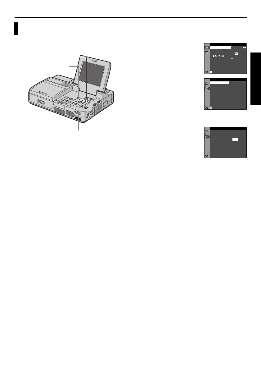
3 Press MENU. The Menu
Screen appears.
4 Press R or T to select the
desired function, and press
MENU. The selected
function menu appears.
5 Press R or T to select the desired function, and
press MENU. The Sub Menu appears.
Switch
U
DMSO N EO
L.V.DENA I
NRET UR
ID O V E
ST RE–EO D
OF. –ARR DV N F
E C–MO D RE
ONCO Y P –
OFPUA IN S/ V T F–
MENUS FOR DETAILED ADJUSTMENT
Example: t VIDEO Menu
Selected menu icon blinks.
6 Press R or T to select the
desired parameter.
7 Press MENU. Selection is
complete.
● Repeat the procedure if
you wish to set other
function menus.
8 Press MENU. The Menu
Screen returns.
● Repeat the procedure if you wish to set other
function menus.
9 Press MENU again. The Menu Screen closes.
NOTES:
● The “n” (DISPLAY) settings are effective only for
video playback.
● The date indication can also be turned on/off by
pressing the DISPLAY Button on the remote
control (provided). (墌 pg. 21, 34)
Selected function
V
ID O
E
U
ST RE–EO D
DMSO N EO
OF. –ARR DV N F
E C–MO D RE
ONCO Y P –
L.V.DENA I
OFPUA IN S/ V T F–
NRET UR
Sub Menu
ID O V E
DU
ST RE– EO
DMSO N EO
OU DNSL
OSU D NR
NRET UR
DMSO N EO
NRET UR
L.V.DENA I
ID O V E
ST RE–EO DU
OF. –ARR DV N F
E C–MO D RE
ONCO Y P –
OFPUA IN S/ V T F–
Page 29

PLAYBACK MENUS
EN 29
Video Menu
VIDEO
Playback sound
During tape playback, the player detects the sound
mode in which the recording was made, and plays
the sound back. Select the type of sound to
accompany your playback picture. According to the
menu access explanation on page 28, select
“SOUND MODE” or “DV NARR.” from the Menu
Screen and set it to the desired parameter.
SOUND MODE (Factory-preset: STEREO )
STEREO : Sound is output from both “L” and
“R” channels in stereo.
SOUND L : Sound from the “L” channel is
output.
SOUND R : Sound from the “R” channel is
output.
DV NARR. (Factory-preset: OFF)
OFF: Original sound is output from both “L” and
“R” channels in stereo.
ON: Dubbed sound is output from both “L” and
“R” channels in stereo.
MIX: Original and dubbed sounds are combined
and output in stereo on both “L” and “R”
channels.
NOTES:
● The “SOUND MODE” setting is available for both
12-bit and 16-bit sound. (In previous models’
functions, “12-bit” is called “32 kHz” and “16-bit”
is called “48 kHz”.)
● The player cannot detect the sound mode in which
the recording was made during fast-forward or
rewind. During playback the sound mode is
displayed in the upper left corner.
Recording mode
Allows you to set the video recording mode (SP or
LP) depending on your preference. It is
recommended you use “REC MODE” in VIDEO
Menu when using this player as a recorder during
dubbing. (墌 pg. 34, 36)
REC MODE (Factory-preset: SP)
SP / LP
Dubbing from tape to memory card
COPY (Factory-preset: ON)
OFF: When the SNAP SHOT button is pressed
during tape playback, the playback image pauses
and normal playback will resume after
approximately 6 seconds. (The still image is not
recorded.)
ON: Enables dubbing of images recorded on a
tape to a memory card. (墌 pg. 38)
Deleting thumbnail images
For details, refer to “To delete thumbnail images”
(墌 pg. 33).
NAVI.DEL.
IMAGE SEL. / TAPE SEL. / ALL / RETURN
S-Video/AV input
S/AV INPUT (Factory-preset: OFF)
OFF: Enables audio and video signal output to a
TV, VCR, etc. via the AUDIO (L/R) and VIDEO or
AUDIO (L/R) and S2 connectors. (墌 pg. 20, 36)
ON: Enables audio and video signal input from
the AUDIO (L/R) and VIDEO connectors, or audio
and S-video signal input from the AUDIO (L/R)
and S2 connectors. (墌 pg. 34)
NOTE:
When VIDEO and S2 connectors are simultaneously
connected, S-video signal is input from the S2
connector.
ADVANCED FEATURES
Page 30

30 EN
PLAYBACK MENUS (cont.)
System Menu
SYSTEM
Beep and melody sound
BEEP (Factory-preset: OFF)
OFF: The beep does not sound even when the
operation is performed.
BEEP: The beep sounds when the operation is
performed.
MELODY: Instead of a beep, a melody sounds
when any operation is performed.
Remote control setting
For details, refer to “USING THE REMOTE
CONTROL UNIT” (墌 pg. 39).
REMOTE (Factory-preset: ON)
OFF: Disables the remote control operations.
ON: Enables the remote control operations.
Component video output setting
When connecting the player to a TV or video unit
equipped with component video inputs (墌 pg. 20),
select the output picture size depending on the
connected TV or video unit.
Y/Pb/Pr (Factory-preset: NO CONV.)
NO CONV.: Outputs with the original size.
Signals are output in 480p during recording.
720 to 1080: Converts to 1080i. Signals are
output in 480p during recording.
ALL to 480p: Converts to 480p.
ALL to 480i: Converts to 480i.
ALL to 1080: Converts to 1080i. Select this setting
if your TV is compatible to 1080i input only.
Signals are not output during recording (in any
mode) or playback in DV mode.
NOTE:
Signals are output in 480i during recording or
playback in DV mode regardless of the output
setting.
S-Video output setting
When connecting the player to a 4:3 TV or widescreen TV using the S-video cable (墌 pg. 20), select
the aspect ratio of the connected TV.
S/VIDEO (Factory-preset: 4:3 TV)
16:9 TV: For a TV which has an aspect ratio of
16:9.
4:3 TV: For a TV which has an aspect ratio of 4:3.
i.LINK output setting
During digital tape dubbing, select whether the
video signal outputs according to the Switch setting.
i.LINK OUT (Factory-preset: SW)
SW: Normally, set to this position. Outputs the DV
or MPEG2 format signal selected with the i.LINK
OUT Switch.
AUTO: For future use. If the connected video unit
automatically detects the input signal via an
i.LINK connector, set to “AUTO”.
Picture quality
The Picture Quality mode can be selected to best
match your needs. Two Picture Quality modes are
available: FINE ( ) and STANDARD ( ) (in order
of quality).
QUALITY (Factory-preset: FINE)
FINE / STANDARD
NOTE:
The number of storable images depends on the
selected picture quality as well as the composition
of the subjects in the images and the type of memory
card being used.
Resetting menu settings
RESET
EXECUTE: Resets all settings to the factory-preset.
RETURN: Does not reset all settings to the factory-
preset.
Page 31

EN 31
Display Menu
DISPLAY
Display setting
ON SCREEN (Factory-preset: LCD)
OFF: The player’s display disappears.
LCD: Keeps the player’s display (except the date,
time and time code) from appearing on the
connected TV screen.
LCD/TV: Makes the player’s display appear on
screen when the player is connected to a TV.
Date and time display setting
DATE/TIME (Factory-preset: OFF)
OFF: The date/time do not appear.
AUTO: The date/time are displayed in the
following cases:
•When playback starts. The player displays the
date/time when scenes are recorded.
•When the date is changed during playback.
ON: The date/time are always displayed.
Time code setting
TIME CODE (Factory-preset: OFF)
OFF: Time code is not displayed.
ON: Time code is displayed on the player and on
the connected TV. Frame numbers are not
displayed during recording.
NOTE:
The date indication can also be turned on/off by
pressing the DISPLAY Button on the remote control
(provided). (墌 pg. 21, 34)
Display
ON SCREEN Setting:
DV 2
bi t/NARR.
1
L
12: 34 :24
4
For playback mode,
playback sound, tape
speed and tape running
during video playback.
DATE/TIME Setting:
For date/time.
0
3
'
C
52
ED
5: 03
PM
TIME CODE Setting:
For time code.
Minutes
Seconds
Frames*
* 30 frames = 1 second
ADVANCED FEATURES
Clock adjustment
CLOCK ADJ.
•Allows you to set the current date and time.
(墌 pg. 15)
Page 32

32 EN
NAVIGATION
NAVIGATION Function
The Navigation Function helps you check tape
contents by making thumbnail images on a memory
card.
RT Button
MENU Button
Play/Pause Button (4/9)
Rewind Button (3)
Stop Button (8)
NAVI Button
NAVI STORE Button
Power Swit ch
To find scenes on tape using thumbnail images
(NAVIGATION Search)
1
Load a cassette. (墌 pg. 16)
2 Load a memory card. (墌 pg. 17)
3 Set the Playback Mode switch to “VIDEO”.
4 Set the Power Switch to “ON” while pressing
down the Lock Button located on the switch.
5 Press NAVI during video playback or stop mode.
● The loaded cassette’s
NAVIGATION thumbnail
image screen appears.
● Press 3 to display the
previous page. Press 5
to display the next page.
6 Press R or T to select the desired image, and
press MENU.
● The “NAVIGATION SEARCH” indication
appears blinking and the player starts searching
the tape for the relevant point of the selected
thumbnail image.
To cancel NAVIGATION search midway...
Press 8 or 4/9.
Fast-Forward
Button (5)
Playback Mode
Switch
ONITNAV I GA
TC : 13 : 23 :1 5
1 2 3
4 5 006
3 224YDATE : AM :’30:329AM
To add thumbnail images during video
playback
Perform steps 1 to 4 in “To find scenes on tape
1
using thumbnail images (NAVIGATION Search)”.
2 Press 4/9 to start video playback.
3 Press NAVI STORE at the desired point.
● The “ ” indicator appears briefly and the
image of the point where NAVI STORE is
pressed is stored in the memory card as a
thumbnail image.
● If you use the tape recorded in SD or HD
mode, it will enter the playback pause mode.
To play, press 4/9.
Page 33

EN 33
To delete thumbnail images
1
Load a memory card. (墌 pg. 17)
2 Set the Playback Mode switch to “VIDEO”.
3 Set the Power Switch to “ON” while pressing
down the Lock Button located on the switch.
4 Press MENU. The Menu Screen appears.
5 Press R or T to select “t” (VIDEO), and press
MENU. The VIDEO Menu appears.
ID O V E
6 Press R or T to select
“NAVI.DEL.”, and press
MENU. The Sub Menu
appears.
7 By pressing R or T...
Select “IMAGE SEL.” to
delete the currently displayed thumbnail image.
Select “TAPE SEL.” to delete all thumbnail images
for the tape which contains the currently
displayed image.
Select “ALL” to delete all thumbnail images
stored in the memory card at once.
8 Press MENU. The
NAVIGATION screen
appears.
9 Press R or T to select
“EXECUTE”, and press
MENU.
● Press 3 to display the previous page. Press
5 to display the next page.
● To cancel deletion, select “RETURN”.
● Thumbnail images cannot be deleted during
video playback.
CAUTION:
Do not remove the memory card or perform any
other operation (such as turning off the player)
during deletion. Also, be sure to use the provided
AC Power Adapter/Charger, as the memory card may
be corrupted if the battery becomes exhausted
during deletion. If the memory card becomes
corrupted, initialize it.
NOTE:
Once images are deleted, they cannot be restored.
Check images before deleting.
DU
DMSO N EO
ST– ERE O
OF. –ARR DV N F
E C–MOD RE
ONCO Y P –
L.V.DENA I
OFPUA IN S/ V T F–
NRET UR
IG NANAV T IO
ETEDE L CURRENT ?
3 CED:2060’0 P3M
EXECUTE
RETURN
IMPORTANT:
● Be sure to always use the same tape and memory
card together as they were during recording;
otherwise, the player cannot recognize Tape and
Memory Card IDs to perform NAVIGATION
function properly.
● Check if an appropriate tape and memory card are
loaded when the following messages appear:
“UNABLE TO USE NAVIGATION”, “THIS
MEMORY CARD IS NOT COMPATIBLE”.
● NAVIGATION Search does not work if the current
position is at a blank portion on the tape. Also, do
not leave a blank portion partway through the tape
when recording; otherwise, NAVIGATION
function does not work properly.
● Before recording newly over a recorded tape, be
sure to delete all thumbnail images of the previous
recording from the relevant memory card.
● If you copy thumbnail images from one memory
card to another via a PC, NAVIGATION Search
does not work with the copied memory card.
ADVANCED FEATURES
Page 34

34 EN
DUBBING
Dubbing To Or From A VCR
COMPONENT
COMPONENT
YY
S2S2
PbPb PrPr
VIDEOVIDEO AUDIOAUDIOLLRR
Audio/video cable
(provided)
VCR
To AV
TV
VIDEO
VIDEO
OUT
OUT
To S2
S-video cable
(provided)
1234
A To S-VIDEO* IN or OUT
B Yellow to VIDEO IN or OUT
C White to AUDIO L IN or OUT
D Red to AUDIO R IN or OUT
* Connect when your TV/VCR has an S-VIDEO
IN/OUT connector. In this case, it is not
necessary to connect the yellow video cable.
To use this player as a player
1 Following the illustrations, connect the player
and the VCR. Also refer to page 20.
2 Set the player’s Playback Mode Switch to
“VIDEO”.
3 Set the Power Switch to “ON” while pressing
down the Lock Button located on the switch.
4 Turn on the VCR’s power.
5 Insert the source cassette in the player.
6 Insert the recording cassette in the VCR.
7 Engage the VCR’s AUX and Record-Pause modes.
● Refer to the instruction manual for the VCR.
8 Press 4/9 on the player to start playback of the
source tape.
9 At the point you want to start dubbing, engage
the VCR’s Record mode.
10 To pause dubbing, engage the VCR’s Record-
Pause mode and press 4/9 on the player.
11 Repeat steps 8 – 10 for additional editing. Stop
the VCR and player.
NOTES:
● It is recommended to use the AC Power Adapter/
Charger as the power supply instead of the
battery pack. (墌 pg. 12)
● As the player starts to play your footage, it will
appear on your TV. This will confirm the
connections and the AUX channel for dubbing
purposes.
● Before you start dubbing, make sure that the
indications do not appear on the connected TV. If
they do, they are being recorded onto the new
tape.
To choose whether or not the following displays
appear on the connected TV...
• Date/time
Set “DATE/TIME” to “AUTO”, “ON” or “OFF”.
(墌 pg. 28, 31) Or, press DISPLAY on the remote
control to turn on/off the date indication.
• Time code
Set “TIME CODE” to “OFF” or “ON”.
(墌 pg. 28, 31)
• Indications other than date/time and time code
Set “ON SCREEN” to “OFF”, “LCD” or “LCD/
TV”. (墌 pg. 28, 31)
● Playback images recorded in HD or SD mode with
this player will be converted to DV format (480i)
image.
To use this player as a recorder
1) Perform steps 1 to 3 in the left column.
2) Set “S/AV INPUT” to “ON”. (墌 pg. 28, 29)
3) Set “REC MODE” to “SP” or “LP”. (墌 pg. 28, 29)
4) Insert the recording cassette in this player.
5) Press and hold REC (7), then press 4/9 to
engage the Record-Pause mode. The “ ”
indication appears on the screen.
6) Press 4/9 to start recording. The indication
rotates.
7) Press 8 to stop recording. The indication
stops rotating.
A/V in
Page 35

EN 35
NOTES:
● After dubbing, set “S/AV INPUT” back to “OFF”.
● Analog signals can be converted to digital signals
with this procedure.
● It is also possible to dub from another player.
● Depending on the tape source input, images may
appear with horizontal jitter on the player’s LCD
monitor during dubbing. This does not affect the
actual recording.
Dubbing To Or From A Video Unit
Equipped With An i.LINK
Connector (Digital Dubbing)
Using an i.LINK cable (optional), it is possible to dub
recorded scenes in DV format from the player onto
another video unit equipped with i.LINK connector.
Since a digital signal is sent, there is little if any
image or sound deterioration.
Images recorded in SD or HD mode can be dubbed
only to a D-VHS VCR with HS mode or digital HD
video camera (ex. GR-HD1 or JY-HD10).
MPEG2MPEG2
DVDV
I.LINK OUTI.LINK OUT
To i.LINK Connector
i.LINK cable
(optional)
To i.LINK IN/OUT
i.LINK Output
Select Switch
Video unit equipped
with i.LINK connector
NOTES:
● It is recommended to use the AC Power Adapter/
Charger as the power supply instead of the
battery pack. (墌 pg. 12)
● When using an i.LINK cable, be sure to use the
optional JVC VC-VDV204U i.LINK cable.
● If the remote control is used when both the player
and recorder are JVC video units, both units will
perform the same operation. To prevent this from
happening, press the buttons on both units.
● It is possible to dub in MPEG2 format from a
D-VHS VCR, if the source tape (D-VHS) has been
originally dubbed from this digital HD player or
digital HD video camera (ex. GR-HD1 or
JY-HD10) in MPEG2 format.
To use this player as a player
1 Make sure all units are turned off.
2 Connect this player to a video unit equipped with
an i.LINK input connector using an i.LINK cable
as shown in the illustration.
3 Set this player’s Playback Mode Switch to
“VIDEO”.
4 Set “i.LINK OUT” to “SW”. (墌 pg. 28, 30)
● If, in future, the connected video unit
automatically detects the DV and MPEG2
formats, set “i.LINK OUT” to “AUTO”. In this
case, proceed to step 6.
5 Set the i.LINK Output Select Switch on this player
to “DV” to output scenes recorded in DV mode,
or “MPEG2” to output scenes recorded in HD or
SD mode.
6 Turn on the video unit’s power.
7 Insert the source cassette in this player.
8 Insert the recording cassette in the video unit.
9 Press 4/9 on this player to start playback of the
source cassette.
10 At the point you want to start dubbing, engage
the video unit’s Record mode.
11 To pause dubbing, engage the video unit’s
Record-Pause mode and press 4/9 on this
player.
12 Repeat steps 10 – 11 for additional editing.
Stop the video unit and player.
NOTES:
● If a blank portion or disturbed image is played
back on the player during dubbing, unusual
images may be dubbed or the dubbing may stop.
● If a scene which has been paused during
recording is dubbed to other devices, playback
may stop at the point.
● Do not connect the player through a hub.
ADVANCED FEATURES
CONTINUED ON NEXT PAGE
Page 36

36 EN
DUBBING (cont.)
To use this player as a recorder
Dubbing from other devices in MPEG2 format is
possible if the connected device is another same
model of this unit. It is also possible to dub in
MPEG2 format from a D-VHS VCR, if the source
tape (D-VHS) has been originally dubbed from this
digital HD player in MPEG2 format.
● However, if signals on the D-VHS tape are
originally from an ATSC tuner etc., dubbing from a
D-VHS VCR in MPEG2 format is not possible.
1 Perform step 1 to 4 of “To use this player as a
player” (墌 pg. 35).
2 Set “REC MODE” to “SP” or “LP”. (墌 pg. 28, 29)
3 Turn on the video unit’s power.
4 Insert the source cassette in the video unit.
5 Insert the recording cassette in this player.
6 Press and hold REC (7), then press 4/9 to
engage the Record Pause mode.
● The “ ” indication appears on the
i.LINK in
screen.
7 Press 4/9 again to start recording.
● The indication rotates.
8 Press 4/9 again to engage the Record-Pause
mode.
● The indication stops rotating.
9 Repeat steps 7 – 8 for additional editing. Stop the
video unit and player.
NOTES:
DV to DV dubbing
● If a blank portion or disturbed image is played
back on the player during dubbing, unusual
images may be dubbed or the dubbing may stop.
MPEG2 to MPEG2 dubbing
● It is not possible to dub signals in MPEG2 format
from devices other than D-VHS VCRs or another
same model of this player.
● MPEG2 signals that are copy-guarded may not be
recorded with this player.
● When dubbing MPEG2 video to the player, image
may not appear on the LCD monitor. However, the
recording is performed properly.
Notes on dubbing to a D-VHS VCR
Dubbing cannot be conducted properly when
dubbing a tape which is recorded in both DV and
HD (or SD) mode. In this case, perform the
following procedure.
1) Disconnect the i.LINK cable.
2) Reset the i.LINK device number on the D-VHS
VCR.
● For the operation, refer to the instruction
manual of the D-VHS VCR.
3) Set “i.LINK OUT” to “SW” on this player.
(墌 pg. 28, 30)
4) Set the i.LINK Output Select Switch on this player
to “DV” to output scenes recorded in DV mode,
or “MPEG2” to output scenes recorded in HD or
SD mode.
5) Connect the i.LINK cable again.
6) Start playback on this player, and then start
recording on the D-VHS VCR.
Recording From The Middle Of A Tape
1) Play back a tape or use Blank Search (墌 pg. 19)
to find the spot at which you want to start
recording, then engage the Still Playback mode.
(墌 pg. 18)
NOTES:
● The time code cannot be reset.
● During fast-forwarding and rewinding, the time
code indication does not move smoothly.
● The time code is displayed only when “TIME
CODE” is set to “ON”. (墌 pg. 31)
When a blank portion is recorded on a tape
Time code
00:00:00
Tape
recorded scene
Recording start
Proper recording
point
Time code
00:00:00
Ta pe
recorded scene
Recording start
Already
Recording stop
Already
point
Time code
05:43:21
Time code
05:43:21
Recording start
Blank
point
New
scene
point
Time code
00:00:00
Newly recorded
scene
Recording start
Time code
05:44:00
Latest scene
Recording
start point
point
Page 37

EN 37
Recording Mode
DV (480i):
The player records signals in the interlace scan
mode (half of 525 scanning lines at 1/60th of a
second).
The image will be recorded in an aspect ratio of 4:3.
The DV mode is suitable for playback on a
conventional 4:3-screen TV.
SD (480p):
The player records signals in the progressive scan
mode (525 scanning lines at 1/60th a second at one
time).
The SD mode reduces flickering more effectively
than a recording in DV mode.
The image will be recorded in an aspect ratio of
16:9. The SD mode is suitable for playback on a
wide-screen TV or high definition TV.
HD (720p):
The player records signals in the progressive scan
mode (750 scanning lines at 1/30th of a second for
recording and 1/60th of a second for playback at
one time).
The HD mode enables digital high definition
recording that offers higher picture quality than a
recording in SD or DV mode.
The image will be recorded in an aspect ratio of
16:9. The HD mode is suitable for playback on a
wide-screen TV or high definition TV.
Supported formats
Horizontal lines Vertical lines Aspect ratio
1280 720 16:9 30 Progressive HD
720 480 16:9 60 Progressive SD
720 480 4:3 60 Interlaced DV
Recording modes and features
There are some features which are not available
depending on the recording mode.
Yes: Available
No: Not Available
Features DV SD HD
Frame-By-Frame Playback
(墌 pg. 18)
Slow-Motion Playback (墌 pg. 40)
Playback Zoom (墌 pg. 41)
Audio Dubbing (墌 pg. 42)
Frames per sec.
(PB.)
Scan mode Recording mode
Ye s No N o
Ye s No N o
Ye s No N o
Ye s No N o
ADVANCED FEATURES
Page 38

38 EN
DUBBING (cont.)
Dubbing Still Images Recorded On A Tape To A Memory Card
Still images can be dubbed from a tape to a memory
card.
SNAP SHOT Button
RT Button
MENU Button
Play/Pause Button (4/9)
Playback Mode
Power Switch
1 Load a cassette. (墌 pg. 16)
2 Load a memory card. (墌 pg. 17)
3 Set the Playback Mode Switch to “VIDEO”.
4 Set the Power Switch to “ON” while pressing
down the Lock Button located on the switch.
5 Set “ COPY” to “ON”. (墌 pg. 28, 29)
6 Press 4/9 to start playback.
7 At the point you want to dub, press 4/9 again to
engage Still Playback.
8 To dub the image, press SNAP SHOT.
● The “ ” indication appears during
dubbing.
● The selected image is stored in the memory
card.
NOTES:
● If SNAP SHOT is pressed in step 8 when a
memory card is not loaded, the message
“COPYING FAILED” is displayed.
● To use Playback Special effects with a video image
you wish to dub, perform up to step 8 using the
remote control (provided). (墌 pg. 41)
● Images are dubbed in the following image sizes:
Scenes recorded in HD mode: 1280 x 720 pixels
Scenes recorded in SD mode: 848 x 480 pixels
Scenes recorded in DV mode: 640 x 480 pixels
Switch
Approximate Number of Storable Images
Image Size/Picture
Quality
640 x 480/FINE 30 68 144 297
640 x 480/
STANDARD
848 x 480/FINE 25 55 117 241
848 x 480/
STANDARD
1280 x 720/FINE 10 22 48 99
1280 x 720/
STANDARD
Image Size/Picture Quality
640 x 480/FINE 36 74 149
640 x 480/STANDARD 95 192 388
848 x 480/FINE 29 60 121
848 x 480/STANDARD 79 160 323
1280 x 720/FINE 12 24 49
1280 x 720/STANDARD 31 64 129
SD Memory Card
8 MB 16 MB 32 MB 64 MB
80 178 376 772
66 148 313 643
26 59 125 257
MultiMediaCard
8 MB 16 MB 32 MB
Page 39

USING THE REMOTE CONTROL UNIT
EN 39
The Full-Function Remote Control Unit can operate
this player from a distance. It also makes additional
playback functions possible. (墌 pg. 40, 41)
Installing The Battery
The remote control uses one lithium battery
(CR2025).
1 Pull out the battery holder by inserting a pointed
instrument into the slot.
2 Insert the battery in the holder, and be sure to
have the “+” mark visible.
3 Slide the holder back in until you hear a click.
2
Slot
1
3
1
Beam Effective Area (indoor use)
When using the remote
control, be sure to point it at
the remote sensor. The
transmitted beam’s
approximate effective
distance for indoor use is
5 m (16 ft).
NOTE:
The transmitted beam may not be effective or may
cause incorrect operation when the remote sensor is
directly exposed to sunlight or powerful lighting.
Remote sensor
Buttons And Functions
A Infrared beam transmitting window
B S.SHOT (Snapshot) Button*
C AUDIO Button ........................... (墌 pg. 28, 29)
D PAUSE Button* .................................. (墌 pg. 40)
Up Button* ....................................... (墌 pg. 41)
E SLOW Rewind Button ....................... (墌 pg. 40)
F REW Button* ............................... (墌 pg. 19, 22)
Left Button ....................................... (墌 pg. 41)
G INSERT Button**
H STOP Button*.............................. (墌 pg. 18, 22)
Down Button* .................................. (墌 pg. 41)
I SHIFT Button .................................... (墌 pg. 41)
J START/STOP Button*
K EFFECT ON/OFF Button.................... (墌 pg. 41)
L EFFECT Button................................... (墌 pg. 41)
M SLOW Forward Button ...................... (墌 pg. 40)
N FF Button* ................................... (墌 pg. 19, 22)
Right Button ..................................... (墌 pg. 41)
O PLAY Button*............................... (墌 pg. 18, 22)
P A. DUB Button .................................. (墌 pg. 42)
Q DISPLAY Button ......................... (墌 pg. 21, 34)
R Zoom (T/W) Buttons ........................ (墌 pg. 41)
* Functions the same as each corresponding
button on the player. (墌 pg. 59)
** Unavailable with this player
ADVANCED FEATURES
Page 40

40 EN
.
SLOW Rewind
Left Button
Down Button or
Button
STOP
SHIFT
T
W
Up Button or
PAUSE
SLOW Forward
Button
Right Button
PLAY
Zoom Buttons
USING THE REMOTE CONTROL UNIT (cont.)
Slow-Motion Playback (DV mode only)
Allows slow-speed search in either direction during
video playback.
During normal video playback, press SLOW (YI or
IU) more than approx. 2 seconds.
● After approx. 5 minutes (approx. 20 seconds with
an 80-minute cassette) in Slow Rewind or approx.
5 minutes in Slow Forward, normal playback
resumes.
● To pause Slow-Motion playback, press PAUSE (9).
● To stop Slow-Motion playback, press PLAY (U).
NOTES:
● You can also engage Slow-Motion Playback from
Still Playback by pressing SLOW (YI or IU) more
than approx. 2 seconds.
● During Slow-Motion Playback, due to digital
image processing, the picture may take on a
mosaic effect.
● After SLOW (YI or IU) is pressed and held, the still
image may be displayed for a few seconds,
followed by a blue screen for a few seconds. This
is not a malfunction.
● There may be a small margin between the slowmotion playback start point you chose and the
actual start point for Slow-Motion Playback.
● During Slow-Motion Playback, there will be
disturbances in video and the picture may seem
unstable, especially with steady images. This is not
a malfunction.
Frame-By-Frame Playback (DV mode only)
Allows frame-by-frame search during video
playback.
During normal or still playback, press SLOW (IU)
repeatedly for forward or SLOW (YI) repeatedly for
reverse. Each time SLOW (YI or IU) is pressed, the
frame is played back.
Page 41

EN 41
Playback Zoom (DV mode only)
Magnifies the recorded image up to 10X at any time
during video playback and D.S.C. playback.
1) Press PLAY (U) to start video
playback. Or perform normal
playback of images.
2) At the point you want to zoom
in, press the Zoom Button (T).
● To zoom out, press the Zoom
Button (W).
3) You can move the image on the
screen around to find a particular
portion of the picture. While
holding down SHIFT, press L
(Left), (Right), U (Up) and E
(Down).
● To end zoom, press and hold W until
magnification returns to normal. Or, press
STOP (8) and then press PLAY (U) during video
playback.
NOTES:
● Zoom can also be used during slow-motion and
still playback.
● Due to digital image processing, the quality of the
image may suffer.
Playback Special Effects (DV mode only)
Allows you to add creative effects to the video
playback image that was recorded in DV mode.
The effects that can be used during playback are
CLASSIC FILM, MONOTONE, SEPIA and STROBE.
CLASSIC FILM: Gives recorded scenes a
strobe effect.
MONOTONE: Like classic black and white
films, your footage is shot in B/W.
SEPIA: Recorded scenes have a brownish tint
like old photos.
STROBE: Your recording looks like a series of
consecutive snapshots.
1) To start playback, press PLAY (U).
2) Press EFFECT. The PLAYBACK EFFECT Select
Menu appears.
3) Press EFFECT repeatedly to move the highlight
bar to the desired effect.
● The selected function is activated and after
2 seconds the menu disappears.
● To deactivate the selected effect, press EFFECT
ON/OFF. To reactivate the selected effect press
EFFECT ON/OFF again.
● To change the selected effect, repeat from
step 2 above.
ADVANCED FEATURES
Page 42

42 EN
USING THE REMOTE CONTROL UNIT (cont.)
Audio Dubbing (DV mode only)
The audio track of a tape recorded in DV format can
be customized only when recorded in the 12-bit and
SP modes. (墌 pg. 29)
Microphone
Speaker
Audio
cable
(provided)
Open the cover.
Headphone Connector
1 Play back the tape to locate the point where
editing will start, then press PAUSE (9).
2 While holding A. DUB (D) on the remote
control, press PAUSE (9). The “9D” and “MIC”
indicators appear.
3 Press PLAY (U), then begin “narrating”. Speak
into the microphone.
● To pause dubbing, press PAUSE (9).
4 To end Audio Dubbing, press PAUSE (9), then
STOP (8).
To hear the sound during Audio Dubbing...
Connect optional headphones to the headphone
connector or use the S2, AUDIO(L/R), VIDEO
connector, and set “DV NARR.” to the desired mode;
•“OFF” for the playback sound.
•“ON” for the dubbed sound.
•“MIX” for the playback and dubbed sound.
To hear the dubbed sound during playback…
Set “DV NARR.” to “ON” or “MIX”. (墌 pg. 28, 29)
NOTES:
● When editing onto a tape that was recorded at
12-bit, the old and new soundtracks are recorded
separately.
● If you dub onto a blank space on the tape, the
sound may be disrupted. Make sure you only edit
recorded areas.
● If feedback or howling occurs during TV playback,
move the microphone away from the TV, or turn
down the TV’s volume.
● If you change from 12-bit to 16-bit in mid-
recording and then use the tape for Audio
Dubbing, it is not effective from the point where
16-bit recording began.
● During Audio Dubbing, when the tape moves to
scenes recorded in the LP mode, scenes recorded
in 16-bit audio or a blank portion, Audio Dubbing
stops.
● To perform Audio Dubbing while watching on the
television, make connections. (墌 pg. 20)
● To perform Audio Dubbing with a video unit
connected to the player’s S2, AUDIO(L/R), VIDEO
connector, first set “S/AV INPUT” to “ON” in
VIDEO Menu. (墌 pg. 28, 29)
The “AUX” indication appears instead of “MIC”.
Page 43

SYSTEM CONNECTIONS
Connection To A Personal Computer
[A] Using USB cable
EN 43
To USB connector
USB cable (provided)
To USB
[B] Using i.LINK cable
To i.LINK
[A] Using USB cable
It is possible to do the following things:
● Transfer still images stored on a memory card to a
PC.
[B] Using i.LINK cable
It is also possible to transfer still/moving images to a
PC with an i.LINK connector by using the software
equipped with the PC or commercially available
software.
● Set “i.LINK OUT” to “SW”. (墌 pg. 30)
● Set the i.Link Output Select Switch on this player
to the appropriate mode (墌 pg. 35);
“DV”: when using the DV editing software
“MPEG2”: when using the MPEG2 editing
software
● Set the i.Link Output Select Switch to the
appropriate mode before connecting the i.Link
cable.
NOTES:
● It is recommended to use the AC Power Adapter/
Charger as the power supply instead of the
battery pack. (墌 pg. 12)
● Never connect the USB cable and the i.LINK
cable simultaneously to the player. Connect only
the cable you wish to use to the player.
● Do not connect the player through a hub.
PC
OR
i.LINK cable
(optional)
● When using an i.LINK cable, be sure to use the
optional JVC VC-VDV206U or VC-VDV204U
i.LINK cable depending on the type of i.LINK
connector (4 or 6 pins) on the PC.
● If the PC connected to the player via the USB
cable is not powered, the player does not enter the
USB mode.
● The date/time information cannot be captured into
the PC.
● Refer to the instruction manuals of the PC and
Software.
● The still images can also be transferred to a PC
with an i.LINK connector-equipped capture board.
● The system may not work properly depending on
the PC or capture board you are using.
“USB MODE” and/or “ACCESSING FILES”
appears on the LCD monitor while the PC is
accessing data in the player or the player is
transferring a file to the PC.
NEVER disconnect the USB cable while
“ACCESSING FILES” is displayed on the LCD
monitor since this can result in product damage.
To i. L I NK
connector
PC with i.LINK
connector
ADVANCED FEATURES
Page 44

44 EN
REFERENCES
ITEMS NOTES
V Power (墌 pg. 11) ● Perform charging where the temperature is between 10°C and 35°C (50°F and
V VIDEO PLAYBACK
(墌 pg. 18)
95°F). 20°C to 25°C (68°F to 77°F) is the ideal temperature range for charging. If
the environment is too cold, charging may be incomplete.
● Charging times are for a fully discharged battery pack.
● Charging time varies according to the ambient temperature and the status of the
battery pack.
● To avoid interference with reception, do not use the AC Power Adapter/Charger
near a radio.
● Since the AC Power Adapter/Charger processes electricity internally, it becomes
warm during use. Be sure to use it only in well-ventilated areas.
● When you use the LCD monitor outdoors in direct sunlight, the LCD monitor may
be difficult to see.
● The cassette holder cannot be opened unless a power supply is attached.
● There may be a delay after you open the cassette holder cover until the cassette
holder opens. Do not use force.
● Once the cassette holder is closed, it recedes automatically. Wait until it recedes
completely before closing the cassette holder cover.
● “TAPE END” appears when the tape reaches its end, and the power goes off
automatically if left in this condition for 5 minutes. “TAPE END” also appears
when a cassette at its end is loaded.
DETAILS
Page 45

TROUBLESHOOTING
If, after following the steps in the chart below, the problem still exists, please consult your nearest JVC dealer.
The player is a microcomputer-controlled device. External noise and interference (from a TV, a radio, etc.)
might prevent it from functioning properly. In such cases, first disconnect its power supply unit (battery pack,
AC Power Adapter/Charger, etc.) and wait a few minutes; and then re-connect it and proceed as usual from
the beginning.
EN 45
Power
SYMPTOM POSSIBLE CAUSES CORRECTIVE ACTION
1. No power is supplied. 1. • The power is not connected
properly.
•The battery is dead.
1. •Connect the AC Power
Adapter/Charger securely.
(墌 pg. 12)
•Replace the dead battery
with a fully charged one.
(墌 pg. 11, 12)
Video and D.S.C. Playback
SYMPTOM POSSIBLE CAUSES CORRECTIVE ACTION
2. Play, Rewind and Fast-Forward
functions do not work.
3. The tape is moving, but there is
no picture.
4. Blocks of noise appear during
playback, or there is no
playback picture and the
screen becomes blue.
5. A memory card cannot be
played back.
6. The image on the 4:3 TV is
elongated vertically (squeeze).
7. The screen of the LCD monitor
is blackened or blocks of noise
appear on its right side but 4/
9 is not pressed.
8. When the screen is under
direct sunlight, the screen
becomes red or black for an
instant.
2. •The Playback Mode Switch is
set to “MEMORY”.
3. •Your TV has AV input
terminals, but is not set to its
VIDEO mode.
•The cassette holder cover is
open.
4. •—
•The tape is recorded in LP
mode.
5. •The Playback Mode Switch is
set to “VIDEO”.
6. •This occurs during recording
in HD or SD mode when a
tape (its erase protection tab
is set to “REC”) is loaded.
•The component video cable
and S-video or audio/video
cable are connected
simultaneously.
7. •The S-Video or audio/video
cable is connected and “S/AV
INPUT” (墌 pg. 29) is set to
“ON”.
8. •This is not a malfunction. 8.
2. •Set the Playback Mode
Switch to “VIDEO”.
3. •Set the TV to the mode or
channel appropriate for
video playback. (墌 pg. 20)
•Close the cassette holder
cover. (墌 pg. 16)
4. •Clean the video heads with
an optional cleaning
cassette.
•This is not a malfunction.
5. •Set the Playback Mode
Switch to “MEMORY”.
6. •This is not a malfunction.
•Disconnect either of two
cables.
7. •This is not a malfunction.
After dubbing, set “S/AV
INPUT” back to “OFF”.
—
REFERENCES
Page 46

46 EN
Advanced features
SYMPTOM POSSIBLE CAUSES CORRECTIVE ACTION
9. During recording, the date/
time does not appear.
10. During recording, sound
cannot be heard.
11. Cannot record signals from a
device which is connected to
the i.LINK connector.
TROUBLESHOOTING (cont.)
9. •“DATE/TIME” is set to “OFF”. 9. •Set “DATE/TIME” to “ON”.
10. • The optional headphones are
not connected to the
headphones connector.
11. •The connected device is not
compatible with this player.
(墌 pg. 28, 31)
10. •Connect the optional
headphones to the
headphone connector.
(墌 pg. 59)
11. •Dubbing from other devices
in MPEG2 format is possible
if the connected device is
another same model of this
unit. It is also possible to dub
in MPEG2 format from a DVHS VCR, if the source tape
(D-VHS) has been originally
dubbed from this digital HD
player in MPEG2 format.
Page 47

Other problems
SYMPTOM POSSIBLE CAUSES CORRECTIVE ACTION
12. The CHARGE indicator on the
AC Power Adapter/Charger
does not light.
13. “SET DATE/TIME!” appears. 13. •The built-in clock’s battery
14. There is no picture. 14. •The player is not getting
15. Files stored in the memory
card cannot be deleted.
16. When the player is connected
via the i.LINK connector, the
player does not operate.
17. The rear of the LCD monitor is
hot.
18. Images on the LCD monitor
appear dark or whitish.
19. Colored bright spots appear all
over the LCD monitor.
12. •The temperature of the
battery is extremely high/low.
•Charging is difficult in places
subject to extremely high/
low temperatures.
has run out.
•The previously set date/time
is erased.
power, or some other
malfunction exists.
15. •Files stored in the memory
card are protected.
16. •The i.LINK cable was
plugged/unplugged with
power turned on.
17. •The light used to illuminate
the LCD monitor causes it to
become hot.
18. •In places subject to low
temperature, images become
dark due to the
characteristics of the LCD
monitor. When this happens,
the displayed colors differ
from those that are actually
recorded. This is not a defect
of the player.
•When the LCD monitor’s
fluorescent light reaches the
end of its service life, images
on the LCD monitor become
dark. Consult your nearest
JVC dealer.
19. •The LCD monitor is made
with high-precision
technology. However, black
spots or bright spots of light
(red, green or blue) may
appear constantly on the
LCD monitor.
These spots are not recorded
on the tape. This is not due to
any defect of the unit.
(Effective dots: more than
99.99 %)
EN 47
12. •To protect the battery, it is
recommended to charge it in
places with a temperature of
10°C to 35°C (50°F to 95°F).
(墌 pg. 52)
13. •Consult your nearest JVC
dealer for replacement.
14. •Turn the player’s power off
and on again. (墌 pg. 13)
15. •Remove protection from the
files stored in the memory
card and delete them.
(墌 pg. 24 – 25)
16. •Turn the player’s power off
and on again, then operate it.
17. •Close the LCD monitor to
turn it off or set the Power
Switch to “OFF”, and let the
unit cool down.
18. •Adjust the brightness and
angle of the LCD monitor.
(墌 pg. 14)
REFERENCES
19.
—
CONTINUED ON NEXT PAGE
Page 48

48 EN
TROUBLESHOOTING (cont.)
20. The indicators and the image
color on the LCD monitor are
not clear.
21. The cassette will not load
properly.
22. The memory card cannot be
removed from the player.
23. Picture does not appear on the
LCD monitor.
24. Images on the LCD monitor
are jittery.
25. The LCD monitor has become
dirty (ex. fingerprints).
26. Time code does not appear. 26. • “TIME CODE” is set to
27. An error indication (E01, E02
or E06) appears.
28. An error indication (E03 or
E04) appears.
29. The remote control does not
work.
20. •This may occur when the
surface or the edge of the
LCD monitor is pressed.
21. •The battery’s charge is low. 21. • Install a fully charged battery.
22.
23. •The LCD monitor’s brightness
setting is too dark.
24. •The speaker volume is too
great.
25.
“OFF”.
27. •A malfunction of some kind
has occurred. In this case the
player’s functions become
unusable.
28. •A malfunction of some kind
has occurred. In this case the
player’s functions become
unusable.
29. •“REMOTE” is set to “OFF”.
•The remote control does not
point at the remote sensor.
•The remote control batteries
are exhausted.
—
—
20.
—
(墌 pg. 11, 12)
22. •Push in the memory card a
few more times. (墌 pg. 17)
23. •Adjust the brightness of the
LCD monitor. (墌 pg. 14)
24. •Turn the speaker volume
down. (墌 pg. 18)
25. •Wipe them gently with soft
cloth. Wiping strongly can
cause damage. (墌 pg. 55)
26. •Set “TIME CODE” to “ON”.
(墌 pg. 28, 31)
27. •墌 pg. 51.
28. •墌 pg. 51.
29. •Set “REMOTE” to “ON”.
(墌 pg. 28, 30)
•Point at the remote sensor.
(墌 pg. 39)
•Replace the batteries with
fresh ones. (墌 pg. 39)
Page 49

Warning Indications
Indications Meaning
Displays the battery remaining power.
Remaining power level: high
Remaining power level: exhausted
As the battery power comes close to nil, the battery indicator blinks.
When the battery power is exhausted, power turns off automatically.
Appears when no tape is loaded. (墌 pg. 16)
CHECK TAPE’S ERASE
PROTECTION TAB
USE CLEANING
CASSETTE
CONDENSATION
OPERATION PAUSED
PLEASE WAIT
TAPE!
TAPE END Appears when the tape ends during recording or playback. (墌 pg. 44)
CAN NOT PLAY BACK
THIS TAPE
CAN NOT DISPLAY
ON LCD MONITOR
IN THIS MODE
Appears if the erase protection tab is set to “SAVE” when the REC (7) Button is
pressed when dubbing.
Appears if dirt is detected on the heads during recording. Use an optional
cleaning cassette.
Appears if condensation occurs. When this indication is displayed, wait more
than 1 hour until condensation disappears.
Appears if a tape is not loaded when the REC (7) Button is pressed when
dubbing.
Appears when you attempt to play back a tape that is not compatible with this
player.
Appears when dubbing a scene recorded in HD mode through the component
video connectors. (墌 pg. 35)
EN 49
CONTINUED ON NEXT PAGE
REFERENCES
Page 50

50 EN
Warning Indications
Indications Meaning
i.LINK CONNECTION
ERROR! CHECK
CABLE CONNECTION
TO CHANGE i.LINK
OUTPUT SETTING,
DISCONNECT i.LINK
CABLE, FIRST
INVALID DATA!
CAN NOT INPUT
COPY PROTECTED
CAN NOT INPUT
CAN NOT DECODE
VIDEO OR AUDIO
A. DUB ERROR! Appears if Audio Dubbing is attempted on a blank portion of a tape. (墌 pg. 42)
A. DUB ERROR!
<MPEG2 RECORDED>
<CANNOT DUB ON A
LP RECORDED TAPE>
<CANNOT DUB ON A
16bit RECORDING>
<CHECK TAPE’S
ERASE PROTECTION
TAB>
Appears when an i.LINK cable is connected but not detected. Disconnect the
cable once and connect it again, or disconnect other connected cables.
Appears when you attempt to change the i.LINK output mode while an i.LINK
cable is connected. (墌 pg. 35)
Appears when you attempt to dub signals which are copygurded or not
compatible with this player through an i.LINK cable.
● Appears if Audio Dubbing is attempted on a tape recorded in SD or HD mode.
● Appears if Audio Dubbing is attempted on a tape recorded in the LP mode.
● Appears if Audio Dubbing is attempted on a tape recorded in 16-bit audio.
● Appears if A. DUB (D) on the remote control is pressed when the erase
protection tab is set to “SAVE”. (墌 pg. 42)
TROUBLESHOOTING (cont.)
(墌 pg. 35)
(墌 pg. 42)
(墌 pg. 42)
(墌 pg. 42)
Page 51

Warning Indications
Indications Meaning
● Appears if dubbing of copyguarded signals is attempted while this player is
being used as a recorder.
● Appears in the following cases when dubbing still images from a tape to a
COPYING FAILED
MEMORY CARD!
PLEASE FORMAT
NO IMAGES STORED
CARD ERROR!
UNSUPPORTED FILE!
CHECK CARD’S WRITE
PROTECTION SWITCH
E01, E02 or E06
UNIT IN SAFEGUARD
MODE REMOVE AND
REATTACH BATTERY
E03 or E04
UNIT IN SAFEGUARD
MODE EJECT AND
REINSERT TAPE
memory card:
– when no memory card is loaded.
– when the memory card’s memory is full.
– when the memory card is not formatted.
– when a write-protected SD Memory Card is loaded. (墌 pg. 38)
Appears if there is no memory card loaded when you attempt to access data on a
memory card.
Appears when there is a problem with a memory card and its memory is corrupt,
or it has not been initialized. Initialize the memory card. (墌 pg. 27)
Appears if there are no image files stored in the memory card when you attempt
memory card playback.
Appears when the player does not recognize the loaded memory card. Remove
the memory card once and insert it again. Repeat these procedures until no
indication appears. If the indication still appears, the memory card is corrupted.
Appears when playing back a file that is not compatible with DCF or a file with a
size that is not compatible with this player.
● Appears when you attempt to dub digital still images when the write protection
tab on the SD Memory Card is set to the “LOCK” position.
● Appears when you attempt MEMORY SELECT menu operation with a writeprotected SD Memory Card loaded.
The error indications (E01, E02 or E06) show what type of malfunction has
occurred. When an error indication appears, the player turns off automatically.
Remove the power supply (battery, etc.) and wait a few minutes for the indication
to clear. When it does, you can resume using the player. If the indication remains,
consult your nearest JVC dealer.
The error indications (E03 or E04) show what type of malfunction has occurred.
When an error indication appears, the player turns off automatically. Eject the
cassette once and re-insert it, then check if the indication clears. When it does,
you can resume using the player. If the indication remains, consult your nearest
JVC dealer.
EN 51
REFERENCES
Page 52

52 EN
CAUTIONS
When using the AC Power Adapter/Charger in areas
other than the USA
䡲 The provided AC Power Adapter/Charger features
automatic voltage selection in the AC range from
110 V to 240 V.
USING HOUSEHOLD AC PLUG ADAPTER
In case of connecting the unit’s power cord to an AC
wall outlet other than American National Standard
C73 series type use an AC plug adapter, called a
“Siemens Plug”, as shown.
For this AC plug adapter, consult your nearest JVC
dealer.
Plug adapter
Caution on Replaceable lithium battery
The battery used in this device may present a fire or
chemical burn hazard if mistreated.
Do not recharge, disassemble, heat above 100°C
(212°F) or incinerate.
Replace battery with Panasonic (Matsushita Electric),
Sanyo, Sony or Maxell CR2025.
Danger of explosion or Risk of fire if the battery is
incorrectly replaced.
•Dispose of used battery promptly.
•Keep away from children.
•Do not disassemble and do not dispose of in fire.
Battery Packs
The supplied battery pack
is a lithium-ion battery.
Before using the supplied
battery pack or an
optional battery pack, be
sure to read the following
cautions:
1. To avoid hazards…
... do not burn.
... do not short-circuit the terminals. When
transporting, make sure the provided battery
cap is attached to the battery. If the battery cap
is misplaced, carry the battery in a plastic bag.
... do not modify or disassemble.
... do not expose the battery to temperatures
exceeding 60°C (140°F), as this may cause the
battery to overheat, explode or catch fire.
... use only specified chargers.
2. To prevent damage and prolong service life…
... do not subject to unnecessary shock.
... charge in an environment where temperatures
are within the tolerances shown in the chart
below. This is a chemical reaction type
battery — cooler temperatures impede
Terminals
chemical reaction, while warmer
temperatures can prevent complete charging.
... store in a cool, dry place. Extended exposure
to high temperatures will increase natural
discharge and shorten service life.
... fully charge and then fully discharge the
battery every 6 months when storing the
battery pack over a long period time.
... remove from charger or powered unit when
not in use, as some machines use current even
when switched off.
NOTES:
● It is normal for the battery pack to be warm after
charging, or after use.
Temperature Range Specifications
Charging........10°C to 35°C (50°F to 95°F)
Operation ......0°C to 40°C (32°F to 104°F)
Storage ..........–20°C to 50°C (–4°F to 122°F)
● Recharging time is based on room temperature of
20°C (68°F).
● The lower the temperature, the longer recharging
takes.
Cassettes
To properly use and store your cassettes, be sure to
read the following cautions:
1. During use…
... make sure the cassette bears the Mini DV
mark.
... be aware that recording onto prerecorded
tapes automatically erases the previously
recorded video and audio signals.
... make sure the cassette is positioned properly
when inserting.
... do not load and unload the cassette
repeatedly without allowing the tape to run at
all. This slackens the tape and can result in
damage.
... do not open the front tape cover. This exposes
the tape to fingerprints and dust.
2. Store cassettes…
... away from heaters or other heat sources.
... out of direct sunlight.
... where they won’t be subject to unnecessary
shock or vibration.
... where they won’t be exposed to strong
magnetic fields (such as those generated by
motors, transformers or magnets).
... vertically, in their original cases.
Page 53

EN 53
Memory Cards
To properly use and store your memory cards, be
sure to read the following cautions:
1. During use…
... make sure the memory card bears the SD or
MultiMediaCard mark.
... make sure the memory card is positioned
properly when inserting.
2. While the memory card is being accessed
(during recording, playback, deletion,
initialization, etc.)…
... never unload the memory card and never turn
off the player.
3. Store memory cards…
... away from heaters or other heat sources.
... out of direct sunlight.
... where they won’t be subject to unnecessary
shock or vibration.
... where they won’t be exposed to strong
magnetic fields (such as those generated by
motors, transformers or magnets).
LCD Monitor
1. To prevent damage to the LCD monitor,
DO NOT…
... push it strongly or apply any shocks.
... place the player with the LCD monitor on the
bottom.
2. To prolong service life…
... avoid rubbing it with coarse cloth.
3. Be aware of the following phenomena for LCD
monitor use.
These are not malfunctions:
•While using the player, the surface around the
LCD monitor and/or the back of the LCD
monitor may heat up.
•If you leave power on for a long time, the
surface around the LCD monitor becomes hot.
Main Unit
1. For safety, DO NOT…
... open the player’s chassis.
... disassemble or modify the unit.
... short-circuit the terminals of the battery pack.
Keep it away from metallic objects when not
in use.
... allow inflammables, water or metallic objects
to enter the unit.
... remove the battery pack or disconnect the
power supply while the power is on.
... leave the battery pack attached when the
player is not in use.
2. Avoid using the unit…
... in places subject to excessive humidity or
dust.
... in places subject to soot or steam such as near
a cooking stove.
... in places subject to excessive shock or
vibration.
... near a television set.
... near appliances generating strong magnetic or
electric fields (speakers, broadcasting
antennas, etc.).
... in places subject to extremely high (over 40°C
or 104°F) or extremely low (under 0°C or
32°F) temperatures.
3. DO NOT leave the unit…
... in places of over 50°C (122°F).
... in places where humidity is extremely low
(below 35%) or extremely high (above 80%).
... in direct sunlight.
... in a closed car in summer.
... near a heater.
4. To protect the unit, DO NOT…
... allow it to become wet.
... drop the unit or strike it against hard objects.
... subject it to shock or excessive vibration
during transportation.
... carry it by holding the LCD monitor.
... swing it excessively when using the shoulder
strap.
5. Dirty heads can cause the following problems:
•No picture during playback.
•Blocks of noise appear during playback.
•During playback, the Head Clog Warning indicator
“ ” appears.
In such cases, use an optional cleaning cassette.
Insert it and play back. If the cassette is used more
than once consecutively, damage to the video heads
may result. After the player plays back for about 20
seconds, it stops automatically. Also refer to the
cleaning cassette’s instructions.
If, after using the cleaning cassette, the problems still
exist, consult your nearest JVC dealer.
Mechanical moving parts used to move the video
heads and video tape tend to become dirty and
worn out over time. In order to maintain a clear
picture at all times, periodic check-ups are
recommended after using the unit for about 1,000
hours. For periodic check-ups please consult your
nearest JVC dealer.
REFERENCES
CONTINUED ON NEXT PAGE
Page 54

54 EN
CAUTIONS (cont.)
About moisture condensation...
● You have observed that pouring a cold liquid
into a glass will cause drops of water to form on
the glass’ outer surface. This same phenomenon
occurs on the head drum of a player when it is
moved from a cool place to a warm place, after
heating a cold room, under extremely humid
conditions or in a place directly subjected to the
cool air from an air conditioner.
● Moisture on the head drum can cause severe
damage to the video tape, and can lead to
internal damage to the player itself.
Serious malfunctioning
If malfunctioning occurs, stop using the unit
immediately and consult your local JVC dealer.
The player is a microcomputer-controlled device.
External noise and interference (from a TV, a
radio, etc.) might prevent it from functioning
properly. In such cases, first disconnect its power
supply unit (battery pack, AC Power Adapter/
Charger, etc.) and wait a few minutes and then reconnect it and proceed as usual from the
beginning.
Declaration of Conformity
Model Number : CU-VH1U
Trade Name : JVC
Responsible party : JVC AMERICAS CORP.
Address : 1700 Valley Road Wayne,
N J 07470
Telephone Number : 973-317–5000
This device complies with Part 15 of FCC Rules.
Operation is subject to the following two
conditions: (1) This device may not cause harmful
interference, and (2) this device must accept any
interference received, including interference that
may cause undesired operation.
Changes or modifications not approved by JVC
could void the user’s authority to operate the
equipment. This equipment has been tested and
found to comply with the limits for a Class B
digital device, pursuant to Part 15 of the FCC
Rules. These limits are designed to provide
reasonable protection against harmful interference
in a residential installation. This equipment
generates, uses, and can radiate radio frequency
energy and, if not installed and used in
accordance with the instructions, may cause
harmful interference to radio communications.
However, there is no guarantee that interference
will not occur in a particular installation. If this
equipment does cause harmful interference to
radio or television reception, which can be
determined by turning the equipment off and on,
the user is encouraged to try to correct the
interference by one or more of the following
measures:
Reorient or relocate the receiving antenna.
Increase the separation between the equipment
and receiver.
Connect the equipment into an outlet on a
circuit different from that to which the receiver is
connected.
Consult the dealer or an experienced radio/ TV
technician for help.
This Class B digital apparatus complies with
Canadian ICES-003.
Cet appareil numérique de la classe B est
conforme à la norme NMB-003 du Canada.
Page 55

USER MAINTENANCE
EN 55
After Use
1 Turn off the player.
2 Slide and hold OPEN/EJECT in the direction of
the arrow, then pull the cassette holder cover
open until it locks. The cassette holder opens
automatically. Remove the cassette.
3 Press “PUSH HERE” to close the cassette holder.
● Once the cassette holder is closed, it recedes
automatically. Wait until it recedes completely
before closing the cassette holder cover.
4 Slide BATT.RELEASE 1 and remove the battery
pack 2 3.
Cassette holder
Remove.
cover
Cassette
holder
OPEN/EJECT Switch
PUSH HERE
BATT.RELEASE Switch
Cleaning The Player
1 To clean the exterior, wipe gently with a soft
cloth.
Put the cloth in diluted mild soap and wring it
well to wipe off heavy dirt. Then wipe again with
a dry cloth.
2 Press the Monitor Opening Button and open the
LCD monitor. Wipe gently with a soft cloth. Be
careful not to damage the monitor. Close the
LCD monitor.
NOTES:
● Avoid using strong cleaning agents such as
benzine or alcohol.
● Cleaning should be done only after the battery
pack has been removed or other power units have
been disconnected.
● When using a cleaner or chemically treated cloth
refer to the cautions of each product.
REFERENCES
Page 56

56 EN
SPECIFICATIONS
Player
For General
Power supply : DC 6.3 V (Using AC Power Adapter/Charger)
Power consumption : Approx. 6.3 W (DV)/6.9 W (HD, SD)
Dimensions (W x H x D) : 211 mm x 52 mm x 154 mm (8-5/16" x 2-1/16" x 6-1/8")
Weight : Approx. 1005 g (2.3 lbs)
Operating temperature : 0°C to 40°C (32°F to 104°F)
Operating humidity : 35% to 80%
Storage temperature : –20°C to 50°C (–4°F to 122°F)
LCD monitor : 3.5" diagonally measured, LCD panel/TFT active matrix system
Speaker : Monaural
For Video Playback
Signal format :NTSC standard
Cassette : Mini DV cassette
Tape s p e ed : SP: 18.8 mm/s
Maximum recording time
(using 80 min. cassette)
For D.S.C. Playback
Storage media : SD Memory Card/MultiMediaCard
Compression system : JPEG (compatible)
File size : 3 modes
DC 7.2 V (Using battery pack)
(with the LCD monitor closed)
(without cassette, memory card and battery)
Approx. 1145 g (2.6 lbs)
(incl. cassette, memory card and battery)
LP: 12.5 mm/s
: SP: 80 min.
LP: 120 min.
(DV: 640 x 480 pixels/SD: 848 x 480 pixels/HD:1280 x 720 pixels)
Page 57

For Connectors
S2
S-Video input : Y: 0.8 V to 1.2 V (p-p), 75 Ω, analog
C: 0.2 V to 0.4 V (p-p), 75 Ω, analog
S-Video output : Y: 1.0 V (p-p), 75 Ω, analog
C: 0.29 V (p-p), 75 Ω, analog
VIDEO
Video input : Y: 0.8 V to 1.2 V (p-p), 75 Ω, analog
Video output : Y: 1.0 V (p-p), 75 Ω, analog
AUDIO
Audio input : 300 mV (rms), 50 kΩ, analog, stereo
Audio output : 300 mV (rms), 1 kΩ, analog, stereo
Headphone output :Stereo
Microphone input :Stereo
i.LINK
Input/output : 4-pin, IEEE 1394 compliant
USB :5-pin
Y/Pb/Pr output : Y: 1.0 V (p-p), 75 Ω, analog
Pb: 0.7 V (p-p), 75 Ω, analog
Pr: 0.7 V (p-p), 75 Ω, analog
AC Power Adapter/Charger
For General
Power requirement
U.S.A. and Canada : AC 120 Vd, 60 Hz
Other countries : AC 110 V to 240 Vd, 50 Hz/60 Hz
Power consumption : 23 W
Output
Charge :DC 7.2 VG, 1.2 A
VTR :DC 6.3 VG, 1.8 A
EN 57
Specifications shown are for SP mode unless otherwise indicated. E & O.E. Design and specifications subject
to change without notice.
REFERENCES
Page 58

58 EN
INDEX
INDEX Controls, Connectors And Indicators
ON
k
hg
ji
MPEG2MPEG2
DVDV
I.LINK OUTI.LINK OUT
PWXY
A
B
C
D
INDEX NAVI STORENAVIINFO
COMPONENT
VIDEO OUT
LCD MONITOR
MENU
SNAP SHOT
BLANK SEARCH
REC
EFGHI
fQR STU
m
PLAY MODE
VIDEO
MEMORY
M
L
K
J
COMPONENT
COMPONENT
VIDEO
VIDEO
OUT
OUT
YY
PbPb PrPr
S2S2
VIDEOVIDEO AUDIOAUDIOLLRR
baZcd
jl
eV
Page 59

EN 59
Controls
a Menu Button [MENU] (墌 pg. 28)
b Rewind Button [
c Stop Button [8](墌 pg. 18)
d Play/Pause Button [4/9](墌 pg. 18)
e Index Button [INDEX] (墌 pg. 23)
f Information Button [INFO] (墌 pg. 23)
g Navigation Button [NAVI] (墌 pg. 32)
h Thumbnail Storing Button [NAVI STORE]
i Recording Start/Stop Button [REC (7)]
j Playback Mode Switch [VIDEO/MEMORY]
k Blank Search Button [BLANK SEARCH]
l Fast-Forward Button [
m RT Button (墌 pg. 15, 18)
n Snapshot Button [SNAP SHOT] (墌 pg. 38)
o Video Output Mode Switch [COMPONENT
VIDEO OUT/LCD MONITOR] (墌 pg. 13, 34)
p i.LINK Output Select Switch [DV/MPEG2]
q Cassette Open/Eject Switch
[OPEN/EJECT] (墌 pg. 16)
r Monitor Opening Button (墌 pg. 14)
s Power Switch [ON, OFF] (墌 pg. 13)
t Speaker/Headphone Volume Control
[VOLUME +, –] (墌 pg. 18)
u LCD Monitor Brightness Control
[BRIGHT +, –] (墌 pg. 14)
v Battery Release Switch [BATT.RELEASE]
3
](墌 pg. 18)
(墌 pg. 32)
(墌 pg. 34)
(墌 pg. 13)
5
](墌 pg. 18)
(墌 pg. 19)
(墌 pg. 35)
(墌 pg. 11)
Indicators
J Power Lamp
Other Parts
h Cassette Holder Cover (墌 pg. 16)
i Card Cover [MEMORY CARD] (墌 pg. 17)
j Remote Sensor (墌 pg. 39)
k Shoulder Strap Eyelet (墌 pg. 9)
l LCD Monitor (墌 pg. 14)
m Battery Pack Mount (墌 pg. 11)
n Speaker (墌 pg. 18)
Connectors
The connectors are located beneath the covers.
W USB (Universal Serial Bus) Connector
(墌 pg. 43)
X Headphone Connector [ ] (墌 pg. 9, 42)
No sound is output from the speaker when
headphones are connected to this connector.
Y Microphone connector [MIC] (墌 pg. 9)
Open the connector cover, and attach the
optional microphone.
Z Component Video Connectors [Y/Pb/Pr]
(墌 pg. 20)
a S-Video connector [S2] (墌 pg. 20, 34)
b Video Connector [VIDEO] (墌 pg. 20, 34)
c Audio Connectors [AUDIO (L/R)]
(墌 pg. 20, 34, 42)
d Digital Video Connector [i] (i.Link*)
(墌 pg. 35, 36, 43)
* “i” refers to the IEEE1394-1995 industry
specification and extensions thereof. The logo
is used for products compliant with the i.Link
standard.
e DC Input Connector [DC] (墌 pg. 11, 12)
REFERENCES
Page 60

60 EN
21
INDEX Indications
LCD Monitor Indications
During Video Playback
5
4
3
BLANK SEARCH
PUSH "STOP" BUTTON
TO CANCEL
q
a Video Playback Mode Indicator (墌 pg. 37)
b Sound Mode Indicator (墌 pg. 29)
c Blank Search Indicator (墌 pg. 19)
d Thumbnail Storing Indicator (墌 pg. 32)
(Appears while the captured image is being
stored as a thumbnail image in the memory
card.)
e Tape Spe e d (墌 pg. 29)
f •U : Playback
•
5
: Fast-Forward/Shuttle Search
•
3
: Rewind/Shuttle Search
•9 : Pause
•9 U : Forward Frame-By-Frame Playback/
Slow-Motion
•Y 9 : Reverse Frame-By-Frame Playback/SlowMotion
•D : Audio Dubbing
•9D : Audio Dubbing Pause
(Appear while a tape is running.)
g Input Mode Indicator (墌 pg. 34, 36)
h Battery Indicator (墌 pg. 49)
i Date/Time (墌 pg. 31)
j •VOLUME : Volume Level Indicator (Speaker or
headphone) (墌 pg. 18)
(The level indicator g moves.)
•BRIGHT +, – : Brightness Control Indicator
(The level indicator g moves.)
k Time Code* (墌 pg. 31)
* This code is to confirm the location of the
recorded scene on the tape during playback.
Display
g
0
6
i.LINK in
:
9
7
8
(墌 pg. 14)
During D.S.C. Playback
1
BR I GHT
4
a Operation Mode Indicator (墌 pg. 23)
b Folder/File Number (墌 pg. 23)
c Battery Indicator (墌 pg. 49)
d Brightness Control Indicator (墌 pg. 14)
(The level indicator g moves.)
100-0013
g
2
3
12:34:24
Minutes
Seconds
Frames
(30 frames = 1 second)
Page 61

TERMS
TERMS
A
AC Power Adapter/Charger ...........................11, 12
Audio Dubbing ...................................................42
Auto Playback Of Images ....................................22
B
Battery Pack ............................................11, 12, 52
Beep (BEEP) .........................................................30
Blank search ........................................................19
Brightness Adjustment Of The Display ................14
C
Changing The Menu Settings ...............................28
Channels (Left/Right) ...........................................29
Charging The Battery Pack ..................................11
Cleaning The Player ............................................55
Clock adjustment (CLOCK ADJ.) .........................15
Component video output setting (Y/Pb/Pr) ...........20
Connections
Charging .......................................................11
Dubbing ...............................................34 – 38
To A PC ........................................................43
To A TV Or VCR ...........................................20
D
Date/Time
Display (DATE/TIME) ....................................31
Settings .........................................................15
DCF (Design rule for Camera File system) ...........22
Deleting Files (DELETE) .......................................25
Deleting thumbnail images (NAVI.DEL.) ..............29
Display ................................................................31
DPOF Setting (Digital Print Order Format) .....26, 27
Dubbing ......................................................34 – 38
Dubbing from tape to memory card
( COPY) .........................................29, 38
E
Erase Protection .............................................16, 17
F
Fast-Forward The Tape ........................................18
Frame-By-Frame Playback ...................................40
I
i.LINK output setting (i.LINK OUT) ......................30
Index Playback Of Files .......................................23
Indications on the LCD Monitor ..........................60
Initializing A Memory Card (FORMAT) ................27
L
Loading A Cassette ..............................................16
Loading A Memory Card .....................................17
EN 61
M
Memory Card ................................................ 17, 53
Menu Screen
D.S.C. Playback .................................... 23 – 27
DISPLAY ....................................................... 31
SYSTEM ........................................................ 30
VIDEO .......................................................... 29
MultiMediaCard ............................................ 17, 53
N
Navigation (NAVIGATION) ................................32
P
Picture Quality (QUALITY) .................................30
Playback Mode Switch Position ..........................13
Playback sound (SOUND MODE,
NARRATION) ..................................................... 29
Playback Special Effects ...................................... 41
Playback Zoom ................................................... 41
Power Switch Position ........................................13
Protecting Files (PROTECT) ................................. 24
Provided Accessories ............................................7
R
Recording Mode (REC MODE) ............................ 29
Recording Time
Tape ............................................................. 16
Record-Standby .................................................. 34
Remaining Power Level ......................................49
Remote Control ................................................... 39
Remote control setting (REMOTE) ....................... 30
Resetting Menu Settings (RESET) .......................... 30
Resetting The File Name ..................................... 26
Rewind The Tape ................................................ 18
S
SD Memory Card .......................................... 17, 53
Shuttle Search ..................................................... 19
Slow-Motion Playback ........................................ 40
Sound Mode (SOUND MODE) ...........................29
Speaker Volume .................................................. 18
Special Effects (EFFECT)
Classic Film (CLASSIC FILM) ......................... 41
Monotone (MONOTONE) ............................ 41
Sepia (SEPIA) ................................................ 41
Strobe (STROBE) ...........................................41
Specifications ................................................ 56, 57
Still Playback ......................................................18
S-Video output setting (S/VIDEO) ........................ 30
S-Video/AV input (S/AV INPUT) .................... 29, 34
T
Time Code (TIME CODE) .................................... 31
U
Unloading A Cassette .......................................... 16
Unloading A Memory Card .................................17
TERMS
Page 62

62 EN
Page 63

EN 63
Page 64

EN
CU-VH1
COPYRIGHT© 2003 VICTOR COMPANY OF JAPAN, LTD.
US
Printed in Japan
1203-FOH-ID-VP
 Loading...