

Page 1
中
文
○R
LCD VIDEO MONITOR
BEDIENUNGSANLEITUNG : LCD-VIDEO-MONITOR
MANUEL D’INSTRUCTIONS : MONITEUR VIDEO LCD
MANUALE DI ISTRUZIONI : MONITOR VI DEO LCD
INSTRUCCIONES : MONITOR DE VIDEO LCD
使用・明・:液晶・・・・器
LM-17G INSTRUCTIONS
LM-15G
ENGLISH DEUTSCH FRANÇAIS ITALIANO ESPAÑOL
Page 2

INSTRUCTIONS
LCD VIDEO MONITOR
LM-17G
LM-15G
Thank you for purchasing this JVC LCD video monitor. Before using it, read
and follow all instructions carefully to take full advantage of the monitor’s
capabilities.
ENGLISH
(* “LCD” stands for Liquid Crystal Display.)
For Customer Use:
Enter below the Serial No. which is located on the rear of the cabinet. Retain this
information for future reference.
Model No. : LM-17G,LM-15G Serial No. :
Page 3

Contents
Safety Precautions.................................................................................................... 3
Installation.................................................................................................................. 5
Unpacking the Monitor................................................................................................. 5
Controls and Features................................................................................................. 5
Using Y our Monitor .................................................................................................. 7
Turning the Monitor On and Off ................................................................................. 7
Caring for and Cleaning the Monitor .......................................................................... 7
Using the Menu ........................................................................................................ 8
Summary of Control Buttons........................................................................................ 8
Menu Operations......................................................................................................... 8
Using the Monitor in the PC mode............................................................................... 13
Basic Connection Example ..................................................................................... 16
Troubleshooting ....................................................................................................... 17
Specifications............................................................................................................ 18
2
Page 4
SAFETY PRECAUTIONS
In order to prevent any fatal accidents caused by disoperation or mishandling the monitor, be fully aware of all the
following precautions.
WARNINGS
To prevent fire or shock hazard, do not expose this monitor to rain or moisture. Dangerous high voltages are present
inside the unit. Do not remove the back cover of the cabinet. When servicing the monitor, consult qualified service
personnel. Never try to service it yourself.
WARNING: THIS APPARATUS MUST BE EARTHED.
This monitor is equipped with a 3-blade grounding-type plug to satisfy FCC rule. If you are unable to insert the
plug into the outlet, contact your electrician.
FCC NOTICE (U.S.A. only)
CAUTION: Changes or modifications not approved by JVC could void the user’s authority to operate the
equipment.
NOTE: This equipment has been tested and found to comply with the limits for a Class A digital device, pursuant to
Part 15 of the FCC Rules. These limits are designed to provide reasonable protection against harmful interference
when the equipment is operated in a commercial environment. This equipment generates, uses, and can radiate
radio frequency energy and, if not installed and used in accordance with the instruction manual, may cause harmful
interference to radio communications. Operation of this equipment in a residential area is likely to cause harmful
interference in which case the user will be required to correct the interference at his own expense.
PRECAUTIONS
● Use only the power source specified on the unit.
● When not using this unit for a long period of time, or when cleaning it, be sure to disconnect the power plug from
the AC outlet.
● Do not allow anything to rest on the power cord. And do not place this unit where people will tread on the cord. Do
ENGLISH
not overload wall outlets or power cords as this can result in a fire or electric shock.
● Avoid using this unit under the following conditions:
– in extremely hot, cold or humid places,
– in dusty places,
– near appliances generating strong magnetic fields,
– in places subject to direct sunlight,
– in badly ventilated places,
– in automobiles with doors closed.
● Do not cover the ventilation slots while in operation as this could obstruct the required ventilation flow.
● When dust accumulates on the screen surface, clean it with a soft cloth.
3
Page 5
● Unplug this unit from the AC outlet and refer servicing to qualified service personnel under the following conditions:
– when the power cord is frayed or the plug is damaged,
– if liquid has been spilled into the unit,
– if the unit has been dropped or the cabinet has been damaged,
– when the unit exhibits a distinct change in performance.
● Do not attempt to service this unit yourself as opening or removing covers may expose you to dangerous voltage or
other hazards. Always refer servicing to qualified service personnel.
● When replacement parts are required, have the service personnel verify in writing that the replacement parts
he/she uses have the same safety characteristics as the original parts. Use of manufacture’s specified
replacement parts can prevent fire, shock, or other hazards.
● Upon completion of any servicing or repair work to this unit, please ask the service personnel to perform the safety
check described in the manufacturer’s service literature.
● When this unit reaches the end of its useful life, improper disposal could result in a picture tube implosion. Ask
qualified service personnel to dispose of this unit.
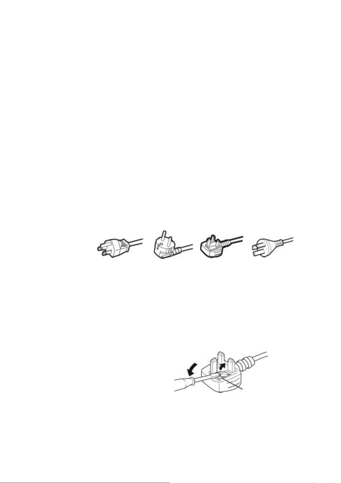
POWER CONNECTION
The power supply voltage rating of this product is AC 120 V (For U.S.A. and Canada only) and AC 230 V (For
European countries or United Kingdom), the power cord attached conforms to the following power supply voltage
and countries. Use only the power cord designated to ensure Safety and EMC regulations of each countries.
Power cord
Power supply voltage : AC 120 V AC 230 V AC 230 V AC 220V
Countries : U.S.A. and Canada European countries United Kingdom China
Warning:
● Do not use the same Power Cord for AC 120 V as for AC 230 V. Doing so may cause malfunction, electric shock or
fire.
Note for the United Kingdom power cord only
The plug on the United Kingdom power cord has a built-in fuse. When replacing the fuse, be sure to use only a
correctly rated approved type, re-fit the fuse cover. (Consult your dealer or qualified service personnel.)
How to replace the fuse
Open the fuse compartment with the blade screw driver,
And replace the fuse.
(* An example is shown in the illustration.)
Fuse
4
Page 6
Installation
Please follow the instructions in this chapter to install your LCD Monitor.
Note: Before connecting your monitor, first read through the instructions in this chapter and the safety precautions in
the previous chapter.
Unpacking the Monitor
When you are unpacking the monitor, make sure that you have the following items:
Ö The LCD monitor
Ö AC power cord
Ö Stand and screw
Ö This instruction book
Note: Place the monitor on a flat, sturdy surfac e. Choose an area free from excessive heat, moisture, and sunlight.
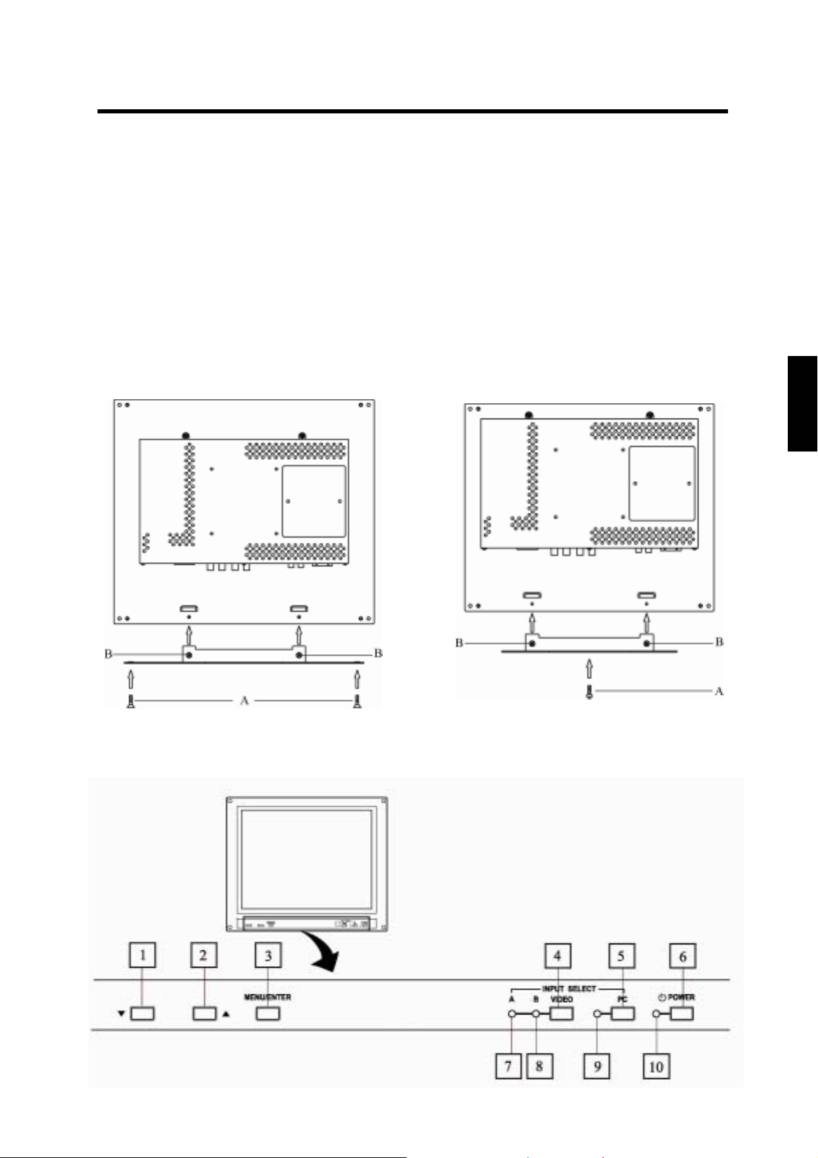
<LM-17G> <LM-15G>
ENGLISH
Attach the supplied stand to the monitor as shown, and then fix it with the screws. Please fix the stand with the
supplied screw (A) first, and then fix it with the screws (B).
Controls and Features
5
Page 7

□1 Down ( ▼ ) button
2
□
UP ( ▲ ) button
3
□
MENU/ENTER button
4
□
Video button
5
□
PC button
□6 Power switch [POWER]
7
□
VIDEO A indicator
8
□
VIDEO B indicator
9
□
PC indicator
□10 Power indicator
To AC outlet
(120 V AC,
50 Hz/60 Hz)
Use this button for menu operation. (See page 8)
Displays the “AUTO SET UP” menu in the PC mode. (See page 13)
Use this button for menu operation. (See page 8)
Displays the “AUTO SET UP” menu in the PC mode. (See page 13)
Use this button for menu operation. (See page 8)
Selects the VIDEO A or B input.
Selects the PC input.
Press this to turn the power on or off.
Lights when VIDEO A input is selected.
Lights when VIDEO B input is selected.
Lights when PC input is selected.
Lights in green when the power is on.
Unlit when the power is off.
Lights in amber when the monitor is in a reduced power mode, when there is
no signal or when the signal is out of range.
For U.S.A. and Canada
To AC outlet
(230 V AC,
50 Hz/60 Hz)
For Europe
To AC outlet
(220 V AC,
50 Hz/60 Hz)
For the United Kingdom
China
□11 AC inlet
□12 VIDEO A terminals
□13 VIDEO B terminals
□14 Remote (external
control) terminals
□15 PC input terminal
□16 AC power cord
(Provided)
Note: For more details about connections, see the "Basic Connection Example" on page 16.
Connect the provided AC power cord 16 to this inlet. Then connect the AC
power cord 16 to the AC outlet (120V AC/220V AC or 230V AC, 50Hz/60Hz)
Video signal input (IN) and output (OUT) terminals for VIDEO A input.
Video signal input (IN) and output (OUT) terminals for VIDEO B input.
Terminals for controlling the monitor from external unit.
You can select input signals, or change the ASPECT RETIO setting via the
Remote terminals.
You can connect this monitor to your PC.
Before using this terminal, please see the "Video Modes (Analog PC signal)”
and “Unknown Video Modes (Analog PC signal)” on page 20.
CAUTION:
In North America (USA and Canada), this monitor comes with one power cord.
In Europe and the United kingdom, two power cords are provided.
Be sure to use the power cable that is appropriate for the AC outlets used in your
region.
If none of the power cord provided is suitable, please contact your dealer or
qualified service personnel to obtain the correct type of power cord.
6
Page 8

Using Your Monitor
This chapter contains information about using your LCD Monitor.
Turning the Monitor On and Off
Use the power button located at the lower right side of the front panel of the monitor to turn the monitor on and off.
When the monitor is on, the Power indicator near the Power button lights green.
The monitor goes into the reduced power mode when there is no video signal input. And then the Power indicator
changes amber from green.
The Power indicator lights amber when the video signal input is out of range .
Note: Because of the technology used in LCD panels, screen savers will not prolong the life of your monitor . So if
the monitor will not be used for an extended period, be sure to turn it off.
Caring for and Cleaning the Monitor
To maximize screen life and prevent damage to the LCD panel, we recommend that you:
Ö Turn the monitor off when you are not using this monitor for a long period of time.
Ö Don’t press, rub, or poke the monitor with your finger or other object.
Ö Handle your monitor with care.
ENGLISH
Your LCD module is a high-quality optical device that requires special care when cleaning.
Warning
To clean the screen:
1. Turn off and unplug the monitor.
2. Gently dust the screen with a dry, soft, line-free cloth.
Note: If the screen is still dirty, you can dampen the cloth with several drops of distilled water. Make sure the LCD
panel is completely dry before you turn the monitor on.
Don’t use liquid, aerosol, or abrasive cleaning solutions to clean the screen.
Connecting the monitor to the PC
When you connect the monitor to a PC, you might be requested to install the specific driver. In this case do the
following:
-use the driver attached with the video card of the PC you use.
or
-set the monitor as standard monitor in the PC menu.Recommended mode, 1024x768 at 60Hz for LM-15G and
1280x1024 at 60Hz for LM-17G .
7
Page 9

Using the Menu
This chapter contains information about how to changing monitor settings for your LCD Monitor. It is designed with
an menu to help you easily adjust to its optimum performance.
Note: In the PC mode, do the “AUTO SET UP” setting first, before adjusting any settings. For details, see “AUTO
SET UP” on page 13.
Summary of Control Buttons
There are three control buttons located at the lower part of the front panel of your monitor:
Ö MENU/ENTER: Display and select a menu. You can also exit a menu by pressing this button repeatedly.
Ö UP(▲): Move upward through the choice in the submenu. If an adjustment bar is displayed, this button increases
the setting value.
Ö Down(▼) : Move downward through the choice in the submenu. If an adjustment bar is displayed, this button
decreases the setting value.
Menu Operation
1. Press the ‘MENU/ENTER’ button to display the “BACK LIGHT” menu..
2. Press the ‘MENU/ENTER’ button repeatedly to display the menu you want to use.
− +100
PICTURE ADJ.
COLOR TEMP.
LOW LIGHT ADJ.
BACK LIGHT
Next page
PICTURE
PHASE
CHROMA
ASPECT
3. Press the ‘UP’ and ‘DOWN’ button to choose the item, and then press the ‘MENU/ENTER’ button to display the
sub-menu.
ASPECT
4:3
16:9
・ If the item do not have sub-menu, go to the step 4.
4. Press ‘UP’ and ‘DOWN’ button to adjust it, or choose a setting.
5. Press the ‘MENU/ENTER’ button repeatedly to exit the menu.
・ To return to the menu from the sub-menu, press the ‘MENU/ENTER’ button
・The menu will disappear if no operation is performed for approximately 15 seconds.
8
Page 10

In the VIDEO A or B mode (composite video input):
Menu Items
BACK LIGHT You can adjust the light output of the backlight.
PICTURE ADJ. PICTURE, PHASE, CHROMA, ASPECT, COLOR TEMP., LOW LIGHT ADJ. .
SYSTEM SETTING SIGNAL LEVEL, DISPLAY, OSD POSITION, COLOR SYSTEM, AGC, REMOTE,
All reset
In the PC mode (analog RGB input):
Menu Items
BACK LIGHT You can adjust the light output of the backlight.
CONTRAST You can adjust the contrast of the picture.
POSITION ADJ. H.POSITION, V. POSITION
WHITE BALANCE
ADJ.
DISPLAY ADJ. AUTO SET UP, CLOCK, PHASE
SYSTEM SETTING DISPLAY, OSD POSITION, REMOTE, All reset
COLOR TEMP., LOW LIGHT ADJ.
BACK LIGHT menu
You can adjust the light output of the backlight.
BACK LIGHT
− +100
PICTURE ADJ. menu
PICTURE ADJ.
Next page
PICTURE
PHASE
CHROMA
ASPECT
COLOR TEMP.
LOW LIGHT ADJ.
PICTURE: You can adjust the levels of black and white on the screen, giving you a darker or brighter picture
overall.
.
ENGLISH
PHASE: You can adjust the picture hue. When the COLOR SYSTEM is BW60, BW50 or PAL, you cannot adjust
the PHASE.
CHOROMA: You can adjust the picture color density. When the COLOR SYSTEM is BW60 or BW50, you cannot
adjust the CHOROMA.
ASPECT: You can choose the screen aspect ratio between “4:3 ” and “ 16:9 ”.
COLOR TEMP.: If you select ‘COLOR TEMP.’ and press the ‘MENU/ENTER’ button, the “COLOR TEMP.” menu will
appear. For details, see the following “COLOR TEMP.” menu.
LOW LIGHT ADJ.: At the video mode: You can adjust the brightness of the dark part of picture.
At the PC mode: You can adjust the R.G.B. balance of the dark part of picture. For details of the
adjustments, see “HIGH LIGHT ADJ.” in page10
Next page: If you select ‘Next page’ and press the ‘MENU/ENTER’ button, the next menu will appear.
9
Page 11

COLOR TEMP. menu
1. Press the ‘UP’ and ‘DOWN’ button to choose the “COLOR TEMP.”, and then press the ‘MENU/ENTER’ button
to display the sub-menu.
COLOR TEMP.
HIGH
NATURAL
LOW
USER
2. Press ‘UP’ and ‘DOWN’ button to choose one of four Color temp settings: HIGH, NATURAL, LOW and USER.
“USER” setting:
You can store the adjustments of “HIGH LIGHT ADJ.” to the “USER” setting.
・ In “HIGH”, “NATURAL” and “LOW”, you cannot use “HIGH LIGHT ADJ.”.
1. Press the ‘UP’ or ‘DOWN’ button to choose the “USER” , and then press the ‘MENU/ENTER’ button to return to
the “HIGH LIGHT ADJ.” menu.
HIGH LIGHT ADJ.
Next page
RED
GREEN
BLUE
2. Press ‘UP’ and ‘DOWN’ button to choose “RED”, and then press ‘MENU/ENTER’ button to display the adjusting
menu.
3. Press ‘UP’ or ‘DOWN’ button to adjust the level, and then press ‘MENU/ENTER’ button to return to the
4. Repeat step 3 and 4 for other colors “GREEN” and “BLUE” to complete the “HIGH LIGHT ADJ.” setting.
−
sub-menu
RED
+
50
10
Page 12

SYSTEM SETTING menu
SYSTEM SETTING
Exit
SIGNAL LEVEL
DISPLAY
OSD POSITION
COLOR SYSTEM
AGC
REMOTE
All reset
SIGNAL LEVEL: You can choose the signal level from ”STD.” or “AMP.”.
STD.: Select this for normal operation.
AMP.: Select this to watch dark part of the picture better.
DISPLAY: If you select ‘DISPLAY’ and press the ‘MENU/ENTER’ button, you can confirm the current status;
resolution, Horizontal frequency and Vertical frequency.
COLOR SYSTEM: You can choose the color system from NTSC, PAL, BW60 or BW50. Choose the correct color
system when the color is abnormal or no color appears.
AGC: You can turn the AGC (Auto Gain Control) function on (ON) or off (OFF).If you select off(OFF), you can adjust
contrast bar.
REMOTE: If you select ON, you can only do remote control. If you select OFF, you can control only by using the
monitor’s buttons.
Exit: If you select “Exit” and press the ‘MENU/ENTER’ button, the menu will disappear.
All reset: If you select “All reset” and press the ‘MENU/ENTER’ button, the settings will be return to the factory
settings.
* “COLOR SYSTEM” and the input select will not be return to the factory settings.
OSD POSITION:
You can adjust the position of the menu on the screen as following procedure.
1. Select “OSD POSITION” and press the ‘MENU/ENTER’ button, the sub-menu will appear.
ENGLISH
OSD POSITION
Next page
H. POSITION
V. POSIT IO N
2. Press ‘UP’ and ‘DOWN’ button to choose “H. POSITION” (horizontal position) or “V. POSITION” (vertical
position), and then press ‘MENU/ENTER’ button to display the adjusting menu
3. Press ‘UP’ and ‘DOWN’ button to adjust the position of the menu on the screen.
4. Press ‘MENU/ENTER’ button to return to the “OSD POSITION” menu.
Next page: If you select ‘Next page’ and press the ‘MENU/ENTER’ button, the next menu will appear.
CONTRAST menu
You can adjust the contrast of the image from the PC.
−
CONTRAST
+ 50
11
Page 13

POSITION ADJ. menu
You can adjust the position of the image from the PC on the screen.
POSITION ADJ.
Next page
H. POSITION
V. POSITION
1. Press ‘UP’ and ‘DOWN’ button to choose “H. POSITION” (horizontal position) or “V. POSITION” (vertical
position), and then press ‘MENU/ENTER’ button to display the adjusting menu
2. Press ‘UP’ and ‘DOWN’ button to adjust the position of the picture on the screen.
3. Press ‘MENU/ENTER’ button to return to the “POSITION ADJ.” menu.
Next page: If you select ‘Next page’ and press the ‘MENU/ENTER’ button, the next menu will appear.
DISPLAY ADJ. menu
You can do the necessary adjustments to display the image from the PC.
DISPLAY ADJ.
Next page
AUTO SET UP
CLOCK
PHASE
AUTO SET UP:
We recommend you to do the AUTO SET UP first. And then adjust the CLOCK or PHASE if necessary.
To use the AUTO SET UP, select this item and press ‘MENU/ENTER’ button. And follow the step 2 of the description
“AUTO SET UP” on page13 .
CLOCK: You can adjust the Clock.
PHASE: You can adjust the Phase.
Next page: If you select ‘Next page’ and press the ‘MENU/ENTER’ button, the next menu will appear.
12
Page 14

Using the Monitor in the PC mode
Since the inherent format of this monitor is 1024 pixels by 768 lines, the monitor will perform best when your PC is
set to a screen resolution of 1024 x 768. If you use a lower resolution (such as 640 x 480), the image is expanded to
fill the screen
Your monitor supports many common video modes, as shown in “Video Modes” on page 20. Check the manuals
supplied with your PC and video adapter card to find out which modes they support. To see what the video mode in
your Microsoft Windows, please check Windows’settings in your PC.
Do the AUTO SET UP first when you use the monitor in the PC mode.
AUTO SET UP
You can setup this monitor to display the analog RGB signal from your PC. Please do the AUTO SET UP whenever
you apply a new video mode or change the refresh rate from the PC.
1. Press ‘UP’ or ‘DOWN’ button while no menu appears on the screen.
The “AUTO SET UP” menu appears on the screen
AUTO SET UP
YES NO
2. Press ‘UP’ or ‘DOWN’ button to choose “YES”, and then press ‘MENU/ENTER’ button to start the AUTO SET
UP.
The monitor will do the necessary settings for new PC input automatically.
AUTO SET UP
Please wait…
When you start the AUTO SET UP, do not display moving images (games, videos, etc) on the screen.
ENGLISH
3. After the AUTO SET UP is complete, you will be asked whether the image is displayed correctly or
not.
AUTO SET UP
Does this image
look correct?
YES NO
4. If the image looks correct, press ‘UP’ or ‘DOWN’ button to choose “YES”.
The menu disappears.
If the image requires further adjustment, press ‘UP’ or ‘DOWN’ button to choose “NO”. “PHASE” menu will
appear and you can adjust the PHASE by ‘UP’ or ‘DOWN’ button.
When all text appears well focused and there is no instability in the image, press the ‘MENU/ENTER’ button.
The menu disappears.
Note: You can also start the AUTO SET UP with “DISPLAY ADJ.” menu.
13
Page 15

The menu flowchart of the VIDEO mode
*The menu can not be displayed when "No Sync" is displayed.
14
Page 16

The menu flowchart of the PC mode
ENGLISH
*The menu cannot be displayed when "No Sync" is displayed.
15
Page 17

)
)
Basic Connection Example
Notes:
・ Before connecting your system, make sure that all devices are turned off.
・ The illustration shows some examples of different connections. Terminal connections may differ depending on
the devices. Be sure to refer to the manuals provided with the devices.
・ Each pair of input (IN) and output (OUT) terminals are bridge-connected
・ If you’re not connecting any equipment to a bridged output (OUT) terminal, be sure not to connect any other
cables to the bridged output (OUT) terminal as this will cause the terminating resistance switch to open (auto
terminate function).
・ When making a bridge connection, connect the input (IN) and output (OUT) terminals on the monitor to separate
video components.(For example, if both terminals are connected to the same VCR, resonance may occur except
during playback. This is caused by the same video signal “looping” between the VCRs, and is not a malfunction.)
・ The ASPECT or INPUT A/B settings can be controlled via the ASPECT or INPUT jack in the REMOTE terminal.
・ When using REMOTE terminal, set REMOTE function ON . See “SYSTEM SETTING menu “ on page 11.
Video Camera
Video Camera
VCR
VCR
Video Monitor
VCR
Video Monitor
Video Monitor
PC
Video Monitor
VCR
External control switch
open circuit (open)
RCA pin
closed circuit (short
External control
functions Open circuit
INPUT INPUT A INPUT B
External control switch
(open)
Closed circuit
(short)
REMOTE
(Remote cable)
Signal Flow
REMOTE
(Remote cable)
External control switch
RCA pin
closed circuit (short
External control
functions
ASPECT
RATIO
open circuit (open)
External control switch
Open circuit
(open)
4 – 3 (4:3) 16 – 9 (16:9)
Closed circuit
(short)
16
Page 18

Troubleshooting
Solutions to common problems related to your monitor are described here. If none of the solutions presented here
solove the problem, unplug the monitor and consult a JVC-authorised dealer or service centre for assistance.
A. My monitor doesn’t work.
Check that the power cable is securely plugged into the monitor.
Check that the monitor is turned on.
Turn the monitor off and pull the plug out, then put the plug in again and turn the monitor on.
B. My monitor shows no colors, wrong color, or dark pictures.
Check that the color system is selected correctly. See “SYSTEM SETTING menu” on page 11.
Check the BACK LIGHT and PICTURE ADJ. settings. See “BACK LIGHT menu” and “PICTURE ADJ.
menu” on page 9.
In the PC mode, check the CONTRAST setting. See “CONTRAST menu” on page 11.
C. Dark stripes appear at the top and bottom of the screen, picture vertically squeezed.
Set the ASPECT setting to “4:3”. See “PICTURE ADJ. menu” on page 9.
D. The message “No Sync” appears .
This message appears when there is no video signal. After few seconds, the monitor goes into the reduced
power mode.
Check the connection.
Select the required video signal input.
Connect the video signal cable firmly.
Check that your graphic card outputs the analog RGB signal.
E. The message “Signal Out of Range” appears on my monitor.
This message appears when the input signal is beyond the monitor capability.
Set your PC to a supported video mode; preferably 1024 x 768 at 60 Hz for LM-15G, 1280x1024 at
ENGLISH
60Hz for LM-17G.
F. The image is very unstable in the PC mode.
Set your PC to a supported video mode; preferably 1024 x 768 at 60 Hz for LM-15G, 1280x1024 at
60Hz for LM-17G.
Restore the original factory settings by “All reset”. See “SYSTEM SETTING menu” on page 11.
Do the “AUTO SET UP”. See “AUTO SET UP” on page 13.
G. When connecting to the PC,installation of the device is required. See "Connecting the monitor to the PC" on
page 7
Note: Even if your PC’s setting is out of the range of video modes that are supported by your LCD monitor, it
may still be displayed with reduced quality. This provides you with an opportunity to change your PC’s
setting to a correct one.
The following are not malfunctions:
・The monitor emits a strange sound when the room temperature changes suddenly. This is only a problem if an
abnormality appears on the screen as well.
・When a still image as been displayed for a long period, a faint residual image may remain on the screen for a short
time after the power has been turned off or when another image is displayed. The image will eventually
disappear.
・When you see the monitor from the side, the color or brightness look different.
・The LCD panel is made with high-precision technology and has more than 99.99% effective pixels.
Fewer than 0.01% of pixels may be chipped or always lit.
17
Page 19

Specifications
Item
Type: LCD Video Monitor
Color system: PAL,NTSC, BW60,BW50
LCD panel:
Display colors: 16700000 colors 16700000 colors
Display area(W x H x D)
Scanning frequency:
Viewing Angle:
Power Input: 100V~240V AC,50Hz/60Hz ,1.2A at 100V ,0.6A at 230V
Input terminals
Video A:
Video B:
PC input: Analog RGB: D-sub (16 pins) x1, positive 0.7V
Model
LM-17G LM-15G
17-in(43.275cm),TFT active matrix
1280 x 1024 dot
337.92mmx270.34mmx432.75mm 304.1mmx228.1mmx380mm
(H) 31.5kHz~80kHz(Analog)
15.734kHz (NTSC)
15.625kHz (PAL)
(V)56Hz~75Hz (Analog)
59.94Hz (NTSC)
50Hz (PAL)
Left/Right 85/85,Up/Down 85/85 Left/Right 60/60,Up/Down 55/45
Composite video:
1line, BNC connector x 2, 1 V(p-p), 75Ω, bridge-connected (auto termination)
Composite video:
1line, BNC connector x 2, 1 V(p-p), 75 Ω,bridge-connected (auto termination)
15-in(38.1cm),TFT active matrix
1204 x 768 dot
(H) 31.5kHz~60kHz(Analog)
15.734kHz (NTSC)
15.625kHz (PAL)
(V)56Hz~70Hz (Analog)
59.94Hz (NTSC)
50Hz (PAL)
PP
Recommended mode:
REMOTE For INPUT: 1 line, RCA pin x 1
REMOTE For ASPECT: 1 line, RCA pin x 1
Conditions Temperature : 5℃~35℃ at altitude 0~2000m,5℃~30℃ at altitude 2000~3000m,
Humidity Altitude: 20%~85%RH,non-condensing 3000m Max.
Storage Conditions
Temperature/Humidity/Altitude:
Maximum power Consumption: 45W 35W
Dimensions
Monitor only(W x H x D):
With supplied stand:
(W x H x D)
Net weight:
100mm mount based on VESA regulation is equipped.
1280 x 1024 at 60Hz (Analog)
-20℃~60℃/ 5%~95% RH/ 10000m Max
402mmx348mmx68.6mm
402mmx349.2mmx162mm
5kg / 5.8kg (with stand)
1024 x 768 at 60Hz (Analog)
370mmx309mmx66.1mm
370 mmx310.6 mmx142 mm
3.75kg / 4.2 kg (with stand)
*Pictures may not appear on the some of PC even if frequencies are within this range.
*Design and specifications subject to change without notice
18
Page 20

Dimensions
<LM-17G>
<Front View>
<Side View>
ENGLISH
<LM-15G>
<Front View>
<Side View>
19
Page 21

Video Modes (Analog RGB Signal)
Your LCD monitor supports the following industry-standard combinations of screen resolution and refresh rates.
For optimum performance, set your PC to the screen resolution of 1024 x 768 at 60 Hz refresh rate.
<LM-17G> <LM-15G>
Supported Resolution
(dots x lines)
VGA
640 x 480
640 x 350
SVGA
XGA
SXGA
US TEXT 720 x 400 70 Hz
Power MAC
800 x 600
800 x 600
1024 x 768
1024 x 768
1280 x 1024 60 Hz
640 x 480 67 Hz
Vertical Frequency
(Refresh Rate)
60 Hz
70 Hz
56 Hz
60 Hz
60 Hz
70 Hz
Supported Resolution
(dots x lines)
VGA
SVGA
XGA
US TEXT
Power MAC
640 x 350
640 x 480
800 x 600
800 x 600
1024 x 768
1024 x 768
720 x 400
640 x 480
Unknown Video Modes (Analog RGB Signal)
Vertical Frequency
(Refresh Rate)
70 Hz
60 Hz
56 Hz
60 Hz
60 Hz
70 Hz
70 Hz
67 Hz
Like all other monitors, the your LCD monitor is designed to work with standard video modes. However, not all
video/graphic cards use only standard display modes.
Your LCD monitor uses state-of-the-art technology, which is designed to synchronize to any display mode. We
recommend choosing one of the supported modes listed above. If you want to use an unknown mode, do the AUTO
SET UP at first. If AUTO SET UP doesn’t make adjustments corrrectly, adjust the CLOCK, PHASE , horizontal
position and vertical position manually.
R
○
VICTOR COMPANY OF JAPAN, LIMITED
20
Page 22

LM-17G /LM-15G LCD VIDEO MONITOR
®
Registered Trademark owned by VICTOR COMPANY OF JAPAN, LTD. P/N: 5030054005
© 2003 VICTOR COMPANY OF JAPAN, LIMITED 1003-MK-TU
VICTOR COMPANY OF J APAN, LIMITED
 Loading...