

Page 1
LCD DISPLAY MONITOR
BEDIENUNGSANLEITUNG: LCD-DISPLAYMONITOR
MANUEL D’INSTRUCTIONS: MONITEUR LCD
ISTRUZIONI: SCHERMO A CRISTALLI LIQUIDI
MANUAL DE INSTRUCCIONES: MONITOR PANTALLA LCD
ENGLISH
DEUTSCHFRANÇAISITALIANOESPAÑOL
LM-170A
LM-150A
INSTRUCTIONS
The illustration of the monitor is of LM-170A.
Die Abbildung des Monitors zeigt das Modell LM-170A.
Les illustrations du moniteur sont du LM-170A.
L’illustrazione del monitor si riferisce al modello LM-170A.
La ilustración muestra el monitor LM-170A.
E030053042
Page 2
Dear Customer,
This apparatus is in conformance with the valid European directives and standards regarding electromagnetic
compatibility and electrical safety.
European representative of Victor Company of Japan, Limited is:
JVC Technology Centre Europe GmbH
Postfach 10 05 52
61145 Friedberg
Germany
Sehr geehrter Kunde, sehr geehrte Kundin,
dieses Gerät stimmt mit den gültigen europäischen Richtlinien und Normen bezüglich elektromagnetischer
Verträglichkeit und elektrischer Sicherheit überein.
Die europäische Vertretung für die Victor Company of Japan, Limited ist:
JVC Technology Centre Europe GmbH
Postfach 10 05 52
61145 Friedberg
Deutschland
Cher(e) client(e),
Cet appareil est conforme aux directives et normes européennes en vigueur concernant la compatibilité
électromagnétique et à la sécurité électrique.
Représentant européen de la société Victor Company of Japan, Limited :
JVC Technology Centre Europe GmbH
Postfach 10 05 52
61145 Friedberg
Allemagne
Gentile Cliente,
Questa apparecchiatura è conforme alle direttive e alle norme europee relative alla compatibilità elettromagnetica e
alla sicurezza elettrica.
Il rappresentante europeo della Victor Company of Japan, Limited è:
JVC Technology Centre Europe GmbH
Postfach 10 05 52
61145 Friedberg
Germania
Apreciado cliente,
Este aparato cumple con las normativas y normas europeas respecto a la seguridad eléctrica y a la compatibilidad
electromagnética.
El representante europeo de Victor Company of Japan, Limited es:
JVC Technology Centre Europe GmbH
Postfach 10 05 52
61145 Friedberg
Alemania
Page 3
LCD DISPLAY MONITOR
ENGLISH
LM-170A
LM-150A
INSTRUCTIONS
The illustration of the monitor is of LM-170A.
Page 4
Safety Precautions
IMPORTANT SAFEGUARDS
Electrical energy can perform many useful functions. This unit has been engineered and manufactured to assure
your personal safety. But IMPROPER USE CAN RESULT IN POTENTIAL ELECTRICAL SHOCK OR FIRE
HAZARD. In order not to defeat the safeguards incorporated into this product, observe the following basic rules for
its installation, use, and service. Please read these “IMPORTANT SAFEGUARDS” carefully before use.
• All the safety and operating instructions should be read before the product is operated.
• The safety and operating instructions should be retained for future reference.
• All warnings on the product and in the operating instructions should be adhered to.
• All operating instructions should be followed.
FCC NOTICE (U.S.A. only)
CAUTION: Changes or modifications not approved by JVC could void the user’s authority to operate the
equipment.
NOTE: This equipment has been tested and found to comply with the limits for a Class B digital device,
pursuant to Part 15 of the FCC Rules. These limits are designed to provide reasonable protection against
harmful interference in a residential installation. This equipment generates, uses and can radiate radio
frequency energy and, if not installed and used in accordance with the instructions, may cause harmful
interference to radio communications. However, there is no guarantee that interference will not occur in a
particular installation. If this equipment does cause harmful interference to radio or television reception, which
can be determined by turning the equipment off and on, the user is encouraged to try to correct the interference
by one or more of the following measures:
– Reorient or relocate the receiving antenna.
– Increase the separation between the equipment and receiver.
– Connect the equipment into an outlet on a circuit different from that to which the receiver is connected.
– Consult the dealer or an experienced radio/TV technician for help.
WARNING: TO REDUCE THE RISK OF FIRE AND ELECTRIC SHOCK, DO NOT EXPOSE THIS
APPARATUS TO RAIN, MOISTURE, DRIPPING OR SPLASHING AND THAT NO OBJECTS
FILLED WITH LIQUIDS, SUCH AS VASES, SHALL BE PLACED ON THE APPARATUS.
IMPORTANT RECYCLING INFORMATION
This product has a fluorescent lamp that contains mercury. Disposal of these materials may be regulated in your
community due to environmental considerations. For disposal or recycling information, please contact your local
authorities or for USA, the Electronic Industries Alliance: http://www.eiae.org
2
Page 5
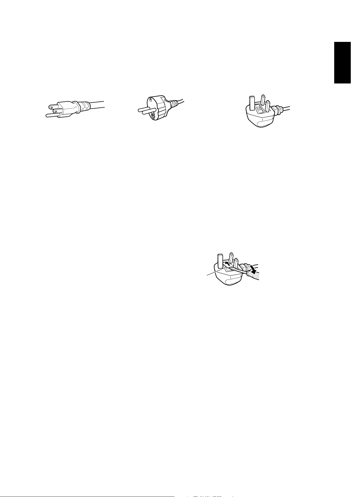
POWER CONNECTION
The power supply voltage rating of this product is AC 100 – 240 V.
The power cord attached conforms to the following power supply voltage and countries. Use only the power cord
designated to ensure safety and EMC regulations of each countries.
For U.S.A. and Canada:
AC 120 V
• This product is equipped with a
grounding-type plug to satisfy FCC
rule. If you are unable to insert the
plug into the outlet, contact your
electrician.
For European and Asian
countries: AC 220 – 240 V
For United Kingdom:
AC 220 – 240 V
• This product should be operated only with the type of power source indicated on the label. If you are not sure of the
type of power supply of your home, consult your product dealer or local power company.
Warning:
• Do not use the same power cord for AC 120 V as for AC 220 – 240 V. Doing so may cause malfunction, electric
shock or fire.
ENGLISH
Note for United Kingdom power cord only
The plug on United Kingdom power cord has a built-in fuse. When replacing the fuse, be sure to use only a correctly
rated approved type, re-fit the fuse cover. (Consult your dealer or qualified personnel.)
How to replace the fuse
Open the fuse compartment with the blade screwdriver, and replace
the fuse.
Fuse
3
Page 6
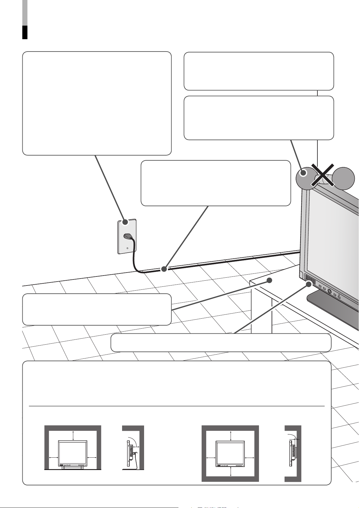
Safety Precautions (cont.)
• Make enough room for inserting or removing the
power plug. Place the product as close to the
outlet as possible. The main power supply for the
product is controlled by inserting or removing the
power plug.
• When the product is left unattended and unused
for long periods of time, unplug it from the wall
outlet and disconnect the cables.
• Do not overload wall outlets, extension cords, or
convenience receptacles on other equipment as
this can result in a risk of fire or electric shock.
• Use only the accessory cord designed for this
product to prevent shock.
• Power-supply cords should be routed so that
they are not likely to be walked on or pinched by
items placed upon or against them. Pay particular
attention to cords at doors, plugs, receptacles, and
the point where they exit from the product.
Do not attempt to service this product yourself, as
opening or removing covers may expose you to
dangerous voltages and other hazards. Refer all
service to qualified service personnel.
• Do not put heavy objects on the product.
• Do not rest your arm on the product or lean
against the product.
• Do not hang on the product when installing the
product on the wall.
The illustration of the
monitor is of LM-170A.
• When the product is used on a table with casters,
lock the casters to prevent the product from falling
over.
• Do not use the monitor for a long time if the sound is distorted. (LM-170A only)
• Do not use this product near water.
• Do not use immediately after moving from a low
temperature to high temperature, as this causes
condensation, which may result in a fire, electric
shock, or other hazards.
When installing the monitor on a stand Unit: mm (inch)
Front view Side view
100
(4)
100 (4)
100
(4)
100 (4)
• Leave the following distance of space (minimum)
around the monitor (see diagram below).
This product may become hot during use. To avoid
overheating, keep enough space around the product
and take enough care when handling the product.
When installing the monitor on the wall
Front view Side view
100 (4)
100
(4)
100 (4)
100
(4)
Unit: mm (inch)
50 (2)
4
Page 7
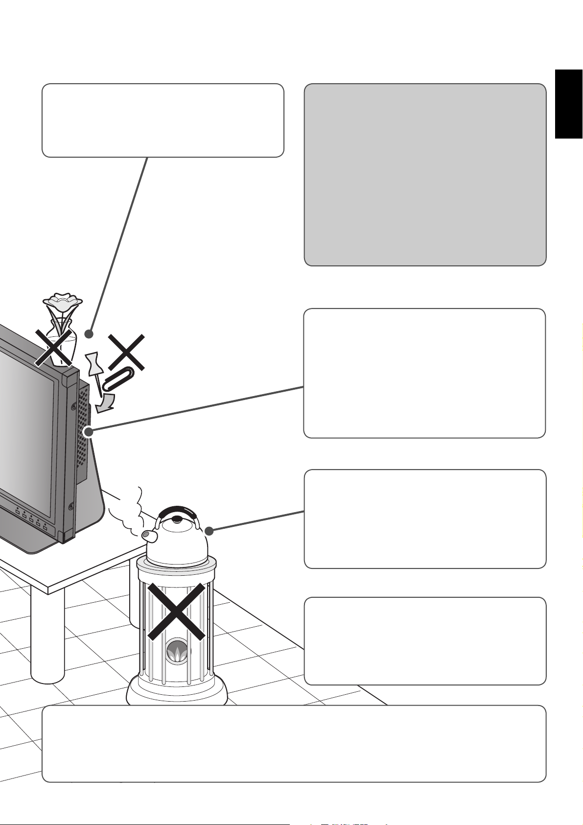
• Never push objects of any kind into this product
through openings as they may touch dangerous
voltage points or short out parts that could result
in a fire or electric shock.
• Never spill liquid of any kind on the product.
Under the following conditions,
1. Turn off the power.
2. Unplug this product from the wall outlet.
3. Refer service to qualified service personnel.
a) When the product emits smoke or unusual smell.
b) When the product exhibits a distinct change
in performance —for example, no picture or no
sound.
c) If liquid has been spilled, or objects have fallen on
the product.
d) If the product has been exposed to rain or water.
e) If the product has been dropped or damaged in
any way.
f) When the power supply cord or plug is damaged.
• Slots and openings in the cabinet are provided
for ventilation. These ensure reliable operation of
the product and protect it from overheating. These
openings must not be blocked or covered.
• The openings should never be blocked by placing
the product on bed, sofa, rug, or similar surface. It
should not be placed in a built-in installation such
as a bookcase or rack unless proper ventilation is
provided and the manufacturer’s instructions have
been adhered to.
ENGLISH
Do not install this product in the following places:
• in a damp or dusty room
• where the product is exposed to soot or steam,
such as near the cooking counter or a humidifier
• near heat sources
• where condensation easily occurs, such as near
the window
• When connecting other products such as VCR’s
and personal computers, you should turn off the
power of this product for protection against electric
shock.
• Do not use attachments not recommended by the
product manufacturer as they may be hazardous.
• When replacement parts are required, be sure the service technician has used replacement parts specified
by the manufacturer or equivalents. Unauthorized substitutions may result in fire, electric shock, or other
hazards.
• Upon completion of any service or repairs to this product, ask the service technician to perform safety
checks to determine that the product is in proper operating condition.
5
Page 8
Safety Precautions (cont.)
Maintenance
Unplug this product from the wall outlet before cleaning.
Screen
To avoid irreparable change in appearance of the screen such as uneven color, discoloration, scratches, be careful
about the following:
• Do not paste or stick anything with any glues or adhesive tapes.
• Do not write anything on the screen.
• Do not strike the screen with a hard object.
• Avoid condensation on the screen.
• Do not wipe the screen with solvent such as alcohol, thinner, or benzine.
• Do not wipe the screen hard.
If the screen gets stained, wipe it with a soft dry cloth, a soft damp cloth, or a soft cloth soaked in water-diluted
neutral detergent and wrung well.
Cabinet
To avoid the deterioration or damages of the cabinet such as its paint’s peeling away, be careful about the following:
• Do not wipe the cabinet using solvent such as alcohol, thinner, or benzine.
• Do not expose the cabinet to any volatile substance such as insecticides.
• Do not remain any rubber or plastic in contact for a long time.
• Do not wipe the cabinet hard.
Wipe stains off the cabinet with a soft cloth. If the cabinet gets heavily stained, wipe it with a soft cloth soaked in
water-diluted neutral detergent and wrung well, and then wipe with a soft dry cloth.
Ventilation openings
• Use a vacuum cleaner to get rid of the dust around the intakes (all the openings). If a vacuum cleaner is not
available, use a cloth and wipe it off. Leaving the dust around the intakes may raise up the internal heat and cause
damage to the product.
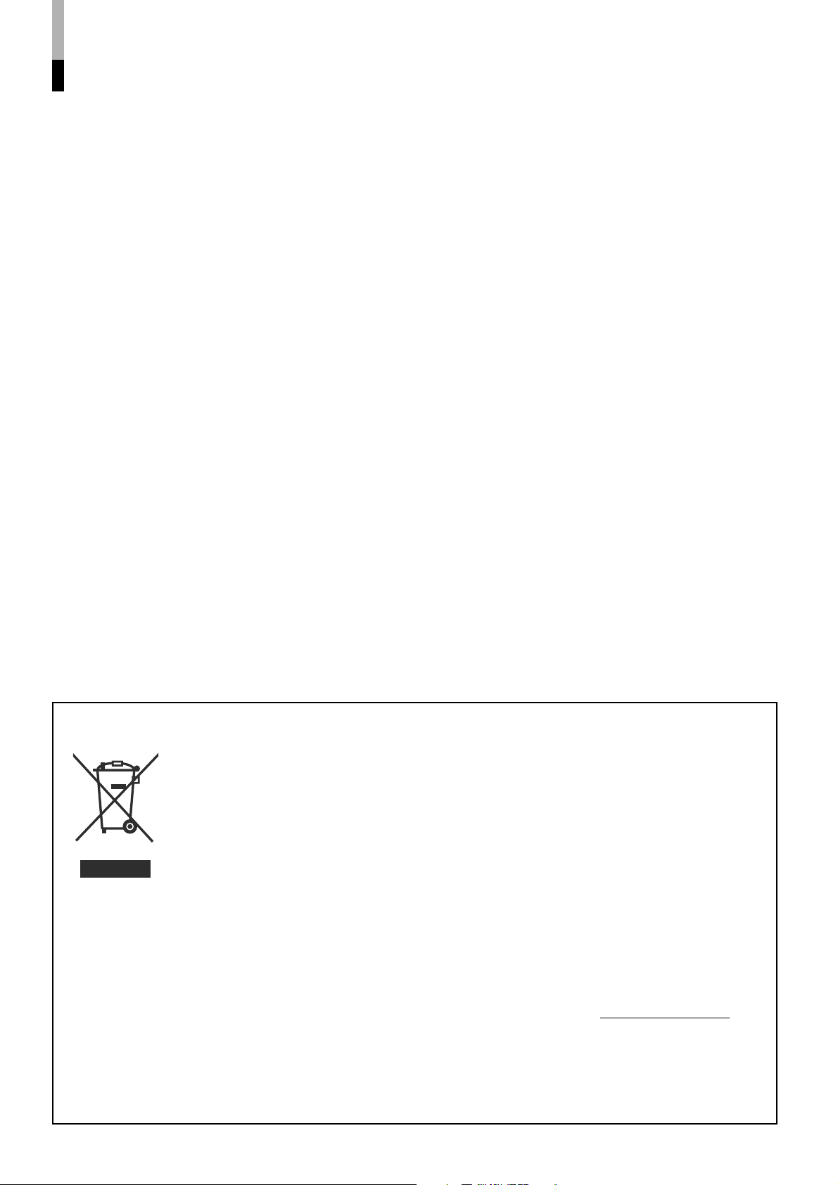
Information for Users on Disposal of Old Equipment
[European Union]
This symbol indicates that the electrical and electronic equipment should not be disposed
as general household waste at its end-of-life. Instead, the product should be handed over
to the applicable collection point for the recycling of electrical and electronic equipment for
proper treatment, recovery and recycling in accordance with your national legislation.
By disposing of this product correctly, you will help to conserve natural resources and will
help prevent potential negative effects on the environment and human health which could
otherwise be caused by inappropriate waste handling of this product. For more information
Attention:
This symbol
is only valid in
the European
Union.
about collection point and recycling of this product, please contact your local municipal
office, your household waste disposal service or the shop where you purchased the
product.
Penalties may be applicable for incorrect disposal of this waste, in accordance with
national legislation.
(Business users)
If you wish to dispose of this product, please visit our web page www.jvc-europe.com to
obtain information about the take-back of the product.
[Other Countries outside the European Union]
If you wish to dispose of this product, please do so in accordance with applicable national
legislation or other rules in your country for the treatment of old electrical and electronic
equipment.
6
Page 9

Contents
Safety Precautions ........................................................ 2
IMPORTANT SAFEGUARDS ................................... 2
Maintenance ............................................................. 6
Controls and Features .................................................. 8
Front panel ............................................................... 8
Rear panel .............................................................. 10
Installation ................................................................... 11
Using the monitor on the stand ............................... 11
Installing the monitor on the wall ............................ 12
Installing the monitor on the rack ............................ 12
How to Use the MAIN MENU ....................................... 13
MAIN MENU items ................................................. 13
How to Use the SET-UP MENU ................................... 14
ENGLISH
SET-UP MENU items .............................................. 15
How to Use the External Control ............................... 17
About the external control ....................................... 17
How to use the MAKE/TRIGGER terminal ............. 17
Troubleshooting .......................................................... 18
Specifications .............................................................. 20
Dimensions ............................................................. 21
Available computer signals ..................................... 22
7
Page 10
Controls and Features
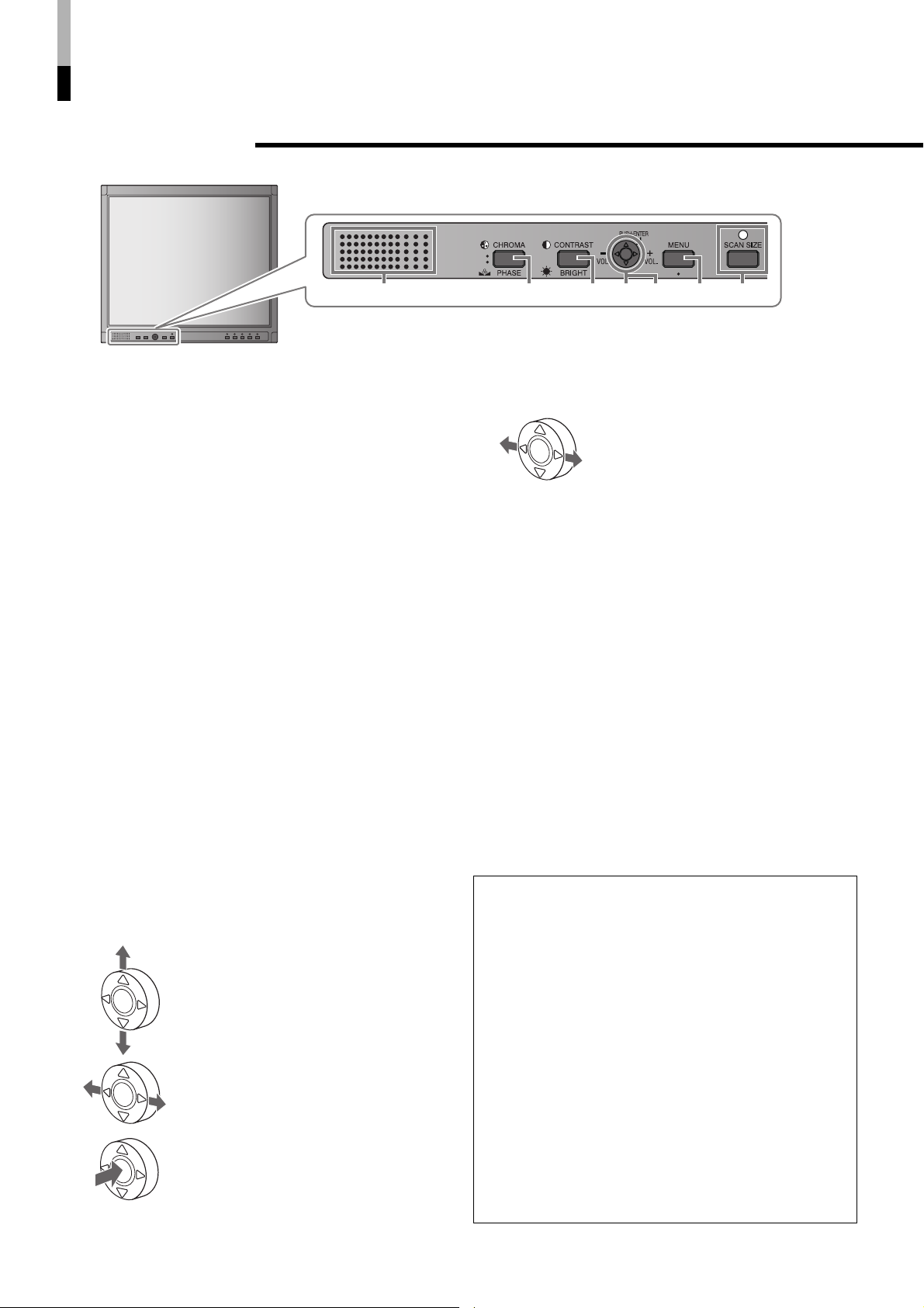
7 Front panel
243 65 71
The illustration of the monitor is of LM-170A.
1 Speaker (Monaural) (LM-170A only)
Outputs the audio signal of the selected input.
NOTE:
• For audio signals input to the DVI-D or RGB terminal,
left and right audio channel are mixed and output as
monaural audio.
2 CHROMA/PHASE button*
Activates the Chroma (picture color density)
adjustment mode or the Phase (picture hue)
adjustment mode.
• Press the button to select the mode, then adjust
the value (–25 - 00 - +25) by pushing the menu
control button (4) left or right.
NOTE:
• Chroma is adjustable when the NTSC or PAL signal is
input.
• Phase is adjustable when the NTSC signal is input.
3 CONTRAST/BRIGHT button*
Activates the picture contrast adjustment mode or
picture brightness adjustment mode.
• Press the button to select the mode, then adjust
the value (–25 - 00 - +25) by pushing the menu
control button (4) left or right.
1
1
4 Menu control button
Operates the menu by pushing or pressing the
button to the indicated direction.
+ pages 13 and 14
Pushing the button up or down:
Selects a menu item.
Pushing the button left or right:
Adjusts the selected menu item.
Pressing the center of the button:
• Goes to the next step.
• Performs the selected function.
5 Volume control button (LM-170A only)*
While the menu is not displayed,
adjust the volume level (00 to 50) by
pushing the button left or right.
2
6 MENU button
Displays the MAIN MENU.
+ page 13
To display the SET-UP MENU:
Press the CHROMA/PHASE button (2) while
pressing the MENU button. (+ page 14)
7 SCAN SIZE button/lamp
Selects the screen size.
OVER = 100% = USER = (back to the beginning)
NOTE:
• Memorized for each input.
• For LM-170A: when “100%” is selected, black bars
appear on the top and the bottom of the screen because
the aspect ratio of the LCD panel is 5:4.
• When “USER” is selected, horizontal/vertical size and
position can be manually adjusted. (+ “SIZE/POSI. ADJ.
(USER)” on page 15)
• When “100%” or “USER” is selected, the lamp lights up.
• This function is not available for the computer signals.
*1 During picture adjustment:
• The adjustment bar will disappear in about 10
seconds after the last operation.
• Pressing MENU will also make the adjustment bar
disappeared.
• “NO EFFECT” is displayed when the operation
you have tried is not available for the current input
or setting.
• The position of the adjustment bar can be
changed. (+ “ADJ. BAR POSI.” on page 13)
*2 During volume adjustment (LM-170A only):
• The adjustment bar will disappear in about 5
seconds after the last operation.
• Pressing MENU will also make the adjustment bar
disappeared.
• The position of the adjustment bar can be
changed. (+ “ADJ. BAR POSI.” on page 13)
8
Page 11

VIDEO 1
NTSC
OVER
The illustration of the monitor is of LM-170A.
ENGLISH
8 p9
8 INPUT SELECT buttons/lamps
Select an input to display.
VIDEO 1: Selects the video signal input to the
VIDEO 1 terminal.
VIDEO 2: Selects the video signal input to the
VIDEO 2 terminal.
DVI: Selects the video signal input to the DVI-
D terminal.
RGB: Selects the video signal input to the RGB
terminal.
• For LM-170A, the corresponding audio signal is
also selected.
9 STANDBY/ON button
Tu r ns on and off (standby) the monitor.
NOTE:
• To disconnect the mains line completely, unplug the AC
plug from the wall outlet.
p Power lamp
Lights in orange:
The monitor is off (standby).
Flashes in orange:
The monitor is in the suspend mode.
Lights in Green:
The monitor is on.
Unlit:
The monitor is off (the AC plug is not
connected).
7 About the status display
When “STATUS DISPLAY” is set to “ON” (+ page
16), the status (information of the current input
and the monitor settings) is displayed for about 5
seconds in the following cases:
• When you press the INPUT SELECT button of the
current input.
• When you change the inputs.
• When the signal condition of the current input
changes.
1 Input status
2 Signal format
• “NO SYNC” is displayed when no video signal
is input.
• When “COLOR SYSTEM” is set to “AUTO”
(+ page 13), “OTHERS” is displayed for a
noncompliant video signal input.
• “Out of range” is displayed for a noncompliant
computer signal input.
3 Setting of SCAN SIZE
+ “7 SCAN SIZE button/lamp” on page 8
NOTE:
• Not displayed for computer signals.
9
Page 12

Controls and Features (cont.)
7 Rear panel
dba
c
2
3
6
The illustration of the monitor is of LM-170A.
1
fe g
4 5
h
1 AC inlet
Power input connector. Connect the provided AC
power cord to an AC outlet (AC 120 V/AC 220 - 240
V, 50 Hz/60 Hz).
2 VIDEO terminals
VIDEO 1 terminals (BNC)
a
Input (IN) and output (OUT) terminals for the
composite signals.
• The IN and OUT terminals are bridgeconnected (auto termination).
• Use the AUDIO 1 terminal* for the audio
connection.
b VIDEO 2 terminals (BNC)
Input (IN) and output (OUT) terminals for the
composite signals.
• The IN and OUT terminals are bridgeconnected (auto termination).
• Use the AUDIO 2 terminal* for the audio
connection.
c AUDIO 1 terminal (pin jack)*
Input terminal for the analog audio signals.
• Use the VIDEO 1 terminal for the video
connection.
d AUDIO 2 terminal (pin jack)*
Input terminal for the analog audio signals.
• Use the VIDEO 2 terminal for the video
connection.
3 REMOTE (external control) terminal (MAKE/
TRIGGER)
Te r minals for controlling the monitor by an external
control.
• Enables the monitor to be controlled by shortcircuiting the pin terminal in this terminal or by
inputting the pulse signal.
+ “How to Use the External Control” on page 17
4 DVI-D terminals
AUDIO terminal (stereo mini jack)*
e
Input terminal for the analog audio signals.
NOTE:
• The built-in speaker of the monitor is monaural.
f DVI-D terminal
Input terminal for the DVI-D signals.
NOTE:
• Use a DVI-D cable with two ferrite cores
(commercially available) to avoid electromagnetic
interference.
5 RGB terminals
AUDIO terminal (stereo mini jack)*
g
Input terminal for the analog audio signals.
NOTE:
• The built-in speaker of the monitor is monaural.
h RGB terminal (D-sub 15-pin)
Input terminal for the analog RGB signals.
10
6 Security slot
Install a security wire to this slot.
* Equipped on LM-170A only
Page 13

Installation
NOTE:
• Do not rest your arm on the monitor or lean against the monitor.
• Do not hold the LCD panel when installing the monitor.
• Make sure to install the monitor securely to prevent the monitor from falling over, which causes damage to the monitor or injury.
• The illustrations of the monitor is of LM-170A.
7 Using the monitor on the stand
You can place the monitor in the following two ways when using the monitor on the supplied stand.
ENGLISH
You can tilt the monitor upward or downward within
the range of about 20° in each direction.
about 20°
about 20°
NOTE:
• Be careful not to pinch your fingers in the gap between the
monitor and the stand.
• Do not tilt the monitor upward more than 20°; otherwise
the monitor may fall over.
• When the monitor is attached to the lower position of the
stand (see below), you cannot tilt the monitor downward.
To adjust the stand height
You can select the stand height—higher
position or lower position.
• For how to detach the stand, see below.
Screw holes
for lower
position
When the monitor is attached to the higher position of
the stand (see below), you can lift the stand up by 90°
and place the monitor as illustrated below.
NOTE:
• Be careful not to pinch your fingers in the moving parts.
• Make sure to lift the stand up until it stops; otherwise the
monitor may fall over.
• Place the monitor on a mat to avoid scratching the table
surface.
• Do not place the monitor in this way when the monitor is
attached to the lower position of the stand.
Screw holes
for higher
position
To detach the stand
NOTE:
• Lay the monitor on a cloth with the LCD panel
facing down to prevent the LCD panel being
damaged.
Screw (M4 x 10)
Stand
VESA mounting holes
Monitor
11
Page 14
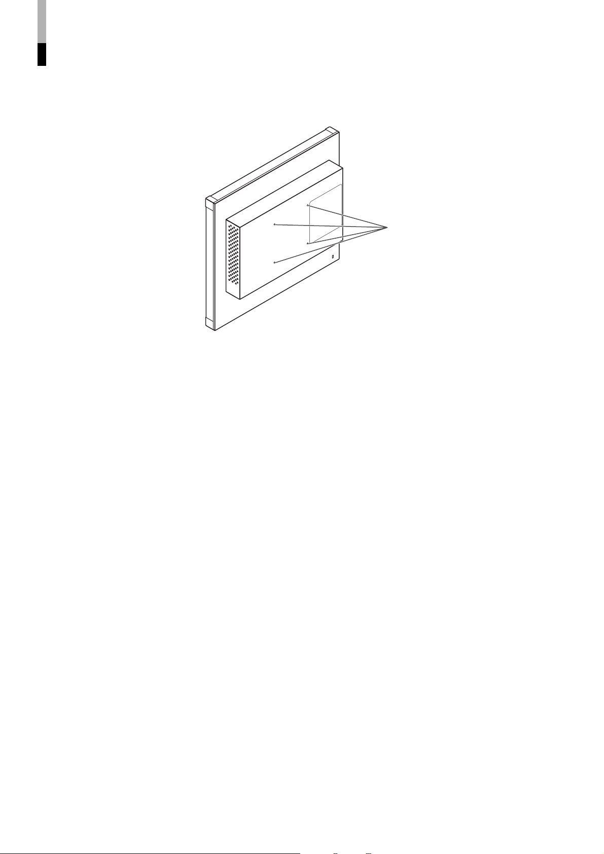
Installation (cont.)
7 Installing the monitor on the wall
Use a commercial wall mounting unit compliant with the VESA standard (100 mm x 100 mm).
NOTE:
• Detach the stand first. (+ page 11)
• Ask your dealer to install.
VESA mounting holes
(See page 21 for the specifications
of the mounting holes.)
7 Installing the monitor on the rack
Use a JVC’s RACK MOUNT ADAPTER (RK-C157L1G; not supplied).
NOTE:
• Detach the stand first. (+ page 11)
• Ask your dealer to install.
12
Page 15

How to Use the MAIN MENU
The MAIN MENU contains the functions for daily use.
MAIN MENU
Select
Adjust
When analog RGB signals are input from the computer
Select “AUTO
ADJ.”
Operation guide
Shows the buttons for
each operation.
7 To exit the menu:
Perform “AUTO
ADJ.”
Select “all
reset”
ENGLISH
NOTE:
• The menu automatically disappears in about 30
seconds after the last menu operation.
• Some items may not appear on the menu. Those
items are not available for the current input or the
current input signal.
7 MAIN MENU items
BACK LIGHT
Adjusts the brightness of the display.
Setting value: 00 - 25
SHARPNESS
Adjusts the clearness of the picture.
Setting value: 00 - 10
CTI.
Adjusts the clearness of the outlines of the color signals
(R/G/B).
Setting value: OFF, NORMAL, HARD
LTI.
Adjusts the clearness of the outlines of the luminance
signal.
Setting value: OFF, NORMAL, HARD
Next
Perform “all reset”
Cancel
ASPECT
Selects the aspect ratio.
Setting value: 4:3, 16:9
NOTE:
• Memorized for each input.
ADJ. BAR POSI.
Selects the position of the adjustment bars.
Setting value: UPPER, LOWER
AUTO ADJ.
Adjusts the position of the picture automatically when
analog RGB signals are input from the computer. By
using this function, the picture is displayed as large as
possible in the effective screen area.
• Adjust the items in “SIZE/POSI. ADJ. (RGB)” (+ page
15) manually when you cannot get a good picture
quality with “AUTO ADJ.”
COLOR SYSTEM
Selects the color system.
Setting value: AUTO, NTSC, PAL
NOTE:
• If the picture is unstable with “AUTO,” select “NTSC” or “PAL.”
all reset
Restores all the settings and adjustments of the
monitor to the factory settings.
• Adjustments made by using the buttons on the
front panel will also be reset.
NOTE:
• “HOUR METER X100h” (+ page 16) and the settings of
“SIZE/POSI. ADJ. (RGB)” (+ page 15) will not be reset.
• After performing “all reset,” the screen goes back to the
MAIN MENU.
13
Page 16

How to Use the SET-UP MENU
The SET-UP MENU contains the initial settings of the monitor.
SET-UP MENU
7 PICTURE SUB ADJ.
Press CHROMA/
PHASE while
pressing MENU.
Operation guide
Shows the buttons for
each operation.
7 To exit the menu:
Select
Next
7 COLOR TEMP.
Select
Adjust
Next
(When selecting “USER1” or
“USER2” in 2)
7 SIZE/POSI. ADJ.
Select
Next
Select
Adjust
Select
“reset”
Perform
“reset”
Select
Adjust
When video signals are input and
“SCAN SIZE” is “USER”
Select
Adjust
NOTE:
• The menu automatically disappears in about
30 seconds after the last menu operation.
• Some items may not appear on the menu.
Those items are not available for the current
input or the current input signal.
• “HOUR METER X100h” shows the total hors of
use of the monitor. This item is not selectable.
Ex. When “ASPECT” is “4:3”
When analog RGB signals are
input from the computer
7 NO SYNC FUNCTION
Select
Next
7 REMOTE SYSTEM
7 STATUS DISPLAY
7 CONTROL LOCK
Select
Adjust
(+ page 16)
7 To go back to the previous screen:
Select
Adjust
Select
Adjust
14
Page 17

7 SET-UP MENU items
PICTURE SUB ADJ.
Sets the standard level for the picture adjustments by using the CHROMA/PHASE and CONTRAST/BRIGHT buttons
on the front panel.
CONTRAST*
BRIGHT*
CHROMA*
PHASE*
reset
1
1
1
1
Adjusts the standard level for contrast adjustment. –20 - 00 - +20
Adjusts the standard level for brightness adjustment. –20 - 00 - +20
Adjusts the standard level for chroma adjustment. –20 - 00 - +20
Adjusts the standard level for phase adjustment. –20 - 00 - +20
Restores the items in “PICTURE SUB ADJ.” to the factory settings.
COLOR TEMP.
Selects the color temperature and adjusts the drive level of each color (R/G/B).
COLOR TEMP.*
R DRIVE
G DRIVE
B DRIVE
1
Selects the color temperature.
• When selecting “USER1” or “USER2,” adjust the R/G/B
drive level below.
Adjusts the drive level of red. –40 - 00 - +40
Adjusts the drive level of green. –40 - 00 - +40
Adjusts the drive level of blue. –40 - 00 - +40
HIGH (9300), LOW (6500),
USER1, USER2
ENGLISH
SIZE/POSI. ADJ. (USER)
Adjusts the position and size of the picture. This item is available only when video signals are input and “SCAN SIZE”
(+ page 8) is set to “USER.”
H. SIZE*
H. POSI.*
V. SIZE (4:3)*
V. SIZE (16:9)*
V. POSI. (4:3)*
V. POSI. (16:9)*
1
1
1
1
1
Adjusts the horizontal picture size. –40 - 00 - +40
Adjusts the horizontal picture position. –40 - 00 - +40
Adjusts the vertical picture size (for 4:3 aspect ratio). –40 - 00 - +40
Adjusts the vertical picture size (for 16:9 aspect ratio). –40 - 00 - +40
Adjusts the vertical picture position (for 4:3 aspect ratio). –40 - 00 - +40
1
Adjusts the vertical picture position (for 16:9 aspect ratio). –40 - 00 - +40
SIZE/POSI. ADJ. (RGB)
Adjusts the position of the picture. This item is available only when analog RGB signals are input from the computer.
H. POSI.*
V. POSI.*
DOT CLOCK*
CLOCK PHASE*
NOTE:
1
*
Memorized for each input.
2
*
Memorized for each signal.
2
2
2
Adjusts the horizontal picture position. 00 - 99
Adjusts the vertical picture position. 00 - 99
Eliminates stripes or flickering by adjusting the both settings.
2
00 - 99
00 - 99
15
Page 18

How to Use the SET-UP MENU (cont.)
REMOTE SYSTEM
Selects the external control system of the MAKE/TRIGGER terminal.
Setting value: MAKE (make contact system), TRIG. (trigger system)
NO SYNC FUNCTION
Selects the screen status when no signal is being input.
NO SYNC DISPLAY
DELAY TIME
STATUS DISPLAY
Selects whether or not to display the status. (+ page 9)
Setting value: ON, OFF
NOTE:
• While this item is set to “ON,” warning messages except “Control lock on!” do not appears.
CONTROL LOCK
Tu r ns on (or off) the control lock function to disable the buttons on the front panel.
Setting value: ON, OFF
NOTE:
• The following operations are available while this function is activated:
– Turning on/off the monitor
– Displaying the SET-UP MENU (by pressing CHROMA/PHASE button while pressing the MENU button) and turning
“CONTROL LOCK” to “OFF”
– Operating the monitor by the external control
If you try other operations, “Control lock on!” appears on the screen.
Sets the screen status when no signal is being input. OFF, SUSPEND (suspend
mode), GRAY (gray screen)
Sets the period until the screen status changes after
signals stop coming in.
5, 20, 60 (seconds, approx.)
HOUR METER X100h
Shows the total hours of use.
NOTE:
• The hour is shown in 100-hour unit.
• The hour is reset to “000” after the total hours of use have reached to “999.”
• Use time less than 1 hour is not accumulated.
16
Page 19

How to Use the External Control
7 About the external control
The monitor has the MAKE/TRIGGER terminal, which allows you to control the monitor by the MAKE (make contact)
or TRIG. (trigger) system.
MAKE (make contact) system: Controls the function by short-circuiting the corresponding pin terminal to the
GND pin terminal, or disconnecting (opening) it.
TRIG. (trigger) system: Controls the function by inputting the pulse signal instantaneously to the
corresponding pin terminal.
* Select “MAKE” or “TRIG.” from “REMOTE SYSTEM” in the SET-UP MENU.
+ “REMOTE SYSTEM” on page 16
NOTE:
• When using the make contact system, you cannot use the buttons on the front panel or menu to utilize functions which are
controlled through the MAKE/TRIGGER terminal. (When using the trigger system, you can also use those functions using the
buttons on the front panel or the menu.)
7 How to use the MAKE/TRIGGER terminal
ENGLISH
No. Functions to be controlled Opening Short-circuiting
1
Changes the input to VIDEO 1 Invalid Valid
2
Changes the input to VIDEO 2 Invalid Valid
3
Changes the input to DVI Invalid Valid
4
This is a female
terminal.
*1 The TRIG. (trigger) system switches each function by short-circuiting for approx. 1 second.
*2 External control (the 7th pin terminal) is controlled by the MAKE (make contact) system even when you select
the “TRIG.” (trigger) system.
Operation
1. Short-circuit the 7th pin terminal (External control) to the 8th pin terminal (GND) so that the monitor can be
controlled externally.
2. When selecting the “MAKE” (make contact) system, operate each function by short-circuiting the
corresponding pin terminal to the 8th pin terminal (GND) or opening it.
When selecting the “TRIG.” (trigger) system, operate each function by pulse control, that is short-circuiting the
corresponding pin terminal to the 8th pin terminal (GND) for about 1 second.
NOTE:
• When controlling No. 1 to 4 pin terminals by the MAKE (make contact) system, only one terminal must be short-circuited. (Other
terminals must be opened.)
• When selecting the “TRIG.” (trigger) system, you can operate only one function at a time. Operate the functions one by one.
Changes the input to RGB Invalid Valid
5
———
6
Changes ASPECT to 16:9 Off On
7
External control Invalid Valid *2
8
GND ——
*1
17
Page 20

Troubleshooting
Solutions to common problems related to your monitor are described here. If none of the solutions presented here
solves the problem, unplug the monitor and consult a JVC-authorized dealer or service center for assistance.
Problems Points to be checked Measures (Remedy)
No power supply
No picture with the
power on
“OTHERS” or “Out
of range” appears.
“NO SYNC”
appears.
No sound (LM-170A
only)
Wrong color, no
color
Unnatural picture
Is the power plug loosened or
disconnected?
Is the signal cable disconnected? Connect the signal cable firmly. 10
Is the power of the connected
component on?
Is the signal being output from the
connected component?
Is the input selected correctly? Select the correct input with the INPUT
Is the input signal adapted to the monitor’s
specification?
Is the input signal adapted to the monitor’s
specification?
Is the signal cable disconnected? Connect the signal cable firmly. 10
Is the input selected correctly? Select the correct input with the INPUT
Is the power of the connected
component on?
Is the signal being output from the
connected component?
Is the signal cable disconnected? Connect the signal cable firmly. 10
Is the signal being output from the
connected component?
Is the volume set to minimum? Adjust the volume level. 8
Has the picture adjustment been changed? Adjust the picture by using the buttons on
Has the white balance setting been
changed?
Is the correct color system selected? Set “COLOR SYSTEM” correctly in the
Has “CONTRAST” or “BRIGHT” been
changed?
Firmly insert the power plug.
Tu rn on the power of the connected
component and set the output correctly.
SELECT buttons.
Check if the input signal format is
acceptable to the monitor.
Check if the input signal format is
acceptable to the monitor.
SELECT buttons.
Tu rn on the power of the connected
component and output video signals.
Or, check if the video output of the
component (video output setting of the
VCR or graphic board of the computer) is
set correctly.
Tu rn on the power of the connected
component and set the output correctly.
the front panel or the items in “PICTURE
SUB ADJ.” in the SET-UP MENU. Or,
perform “reset” in “PICTURE SUB ADJ.”
Change “COLOR TEMP.” in the SET-UP
MENU. Or, perform “all reset” in the MAIN
MENU.
MAIN MENU.
Adjust picture contrast or brightness
by using the buttons on the front panel.
Or, adjust “CONTRAST” or “BRIGHT”
in “PICTURE SUB ADJ.” in the SET-UP
MENU.
Reference
pages
—
—
9
20
20
9
—
—
8, 15
13, 15
13
8, 15
18
Page 21

Problems Points to be checked Measures (Remedy)
Wrong picture
position, wrong
picture size
Some items do not
appear on the menu.
The buttons on the
front panel do not
function.
Installing the driver
is required when
a computer is
connected.
Has the picture position or size been
changed?
Is the input signal adapted to the monitor’s
specification?
Has the SCAN SIZE button been pressed? Press the SCAN SIZE button to select
Is “ASPECT” in the MAIN MENU set to
“16:9”?
The items which are not available for the
current input or the current input signal do
not appear on the menu.
Is “CONTROL LOCK” in the SET-UP
MENU set to “ON”?
Has the monitor’s setting been changed
to enable control by the external control
connected to the REMOTE terminal?
—
Adjust the picture size (H. SIZE/V. SIZE) or
position (H. POSI./V. POSI.) in “SIZE/POSI.
ADJ.” in the SET-UP MENU.
When analog RGB signals are input from
the computer, perform “AUTO ADJ.” in the
MAIN MENU.
For some signals, the picture cannot be
displayed fully in the effective screen area.
There is no sure method to solve this
problem.
Check if the input signal format is
acceptable to the monitor.
“OVER.”
Set it to “4:3.”
Change the input or the input signal.
Set it to “OFF.”
Disable the external control.
Use the driver of the graphic board
installed into your computer (the driver is
supplied with the graphic board).
Or, set the monitor to the standard display.
• Recommended display setting:
1280 x 1024, 60 Hz (LM-170A)
1024 x 768, 60 Hz (LM-150A)
Reference
pages
ENGLISH
13, 15
—
20
8
13
—
16
17
—
The following are not malfunctions:
• When a still image is displayed for a long time, it may remains on the screen after the picture changes. This is
due to the characteristics of the LCD display and is not malfunction. The remaining picture will disappear after
a while.
• The red spots, blue spots and green spots on the panel surface are a normal characteristic of LCD displays,
and not a problem. The LCD display is built with very high precision technology, however, be aware that a few
pixels may be missing or constantly lit.
The following symptoms are problems only when pictures or sounds are not played back normally:
• A slight electric shock occurs when you touch the monitor.
• The top and/or rear panel of the monitor becomes hot.
• The monitor emits a cracking noise.
• The monitor emits a mechanical noise.
19
Page 22

Specifications
Model LM-170A LM-150A
Type
LCD panel
Effective Screen Size
Number of Pixels Displayed
PC Scanning Frequency
Input/Output
Terminals
Compliant Video Signal
Format
Audio Output
Environmental Conditions
Power Requirements
Rated Input Current
Dimensions
Weight
Accessory
VIDEO 1
VIDEO 2
DVI-D
RGB
Video
AUDIO 1
AUDIO 2
AUDIO (DVI-D)
Audio
AUDIO (RGB)
17”, active matrix TFT 15”, active matrix TFT
Width: 337.9 mm (13 1/4”)
Height: 270.3 mm (10 5/8”)
1280 x 1024 1024 x 768
H: 31.5 kHz – 80 kHz
V: 56 Hz – 75 Hz
* Some signals within this frequency range may not be displayed depending on the
computer you use (“Out of range” appears).
Composite video: 1 line, BNC connector x 2, 1 V(p-p), 75 Ω
* The input (IN) and output (OUT) terminals are bridge-connected.
(Auto termination)
DVI-D: DVI-D connector x 1 (compatible with DDC2B)
Analog RGB: D-Sub 15-pin x 1
Video signal: G: 1 V(p-p), 75 Ω (including sync)
Horizontal sync (HD)/Composite sync (Cs):
Vertical sync (VD): 1 V(p-p) – 5 V(p-p) (positive/negative polarity)
* Computer signals are compatible with DDC2B.
Analog audio:
1 line, RCA connector x 1,
500 mV (rms), high impedance
Analog audio:
1 line, Stereo mini jack (φ 3.5 mm) x 1,
500 mV (rms), high impedance
Video signal:
Composite video: NTSC, PAL, B/W (50 Hz/60 Hz)
Computer signal:
DVI-D: + “Available computer signals” on page 22
Analog RGB: + “Available computer signals” on page 22
Internal: 1 W (monaural)
Operating temperature: 5°C – 35°C (41°F – 95°F)
Operating humidity: 20% – 85% (non-condensing)
AC 100 - 240 V, 50 Hz/60 Hz
0.9 A 0.9 A
Width: 374 mm (14 3/4”) 374 mm (14 3/4”)
Height: 373.6 mm (14 3/4”) 334 mm (13 1/4”)
Depth: 184 mm (7 1/4”) 70.5 mm (2 7/8”)
7.2 kg (15.8 lbs) (including the stand)
4.6 kg (10.1 lbs) (excluding the stand)
AC power cord
(with the stand) (without the stand)
LCD Display Monitor
Width: 304.1 mm (11 15/16”)
Height: 228.1 mm (8 15/16”)
H: 31.5 kHz – 60 kHz
V: 56 Hz – 75 Hz
R, B: 0.7 V(p-p), 75 Ω
1 V(p-p) – 5 V(p-p) (positive/negative polarity)
Width: 342 mm (13 1/2”) 342 mm (13 1/2”)
Height: 330.6 mm (13 1/8”) 291 mm (11 1/2”)
Depth: 184 mm (7 1/4”) 70.5 mm (2 7/8”)
6.2 kg (13.6 lbs) (including the stand)
3.6 kg (7.9 lbs) (excluding the stand)
(with the stand) (without the stand)
* Illustrations and pictures used in this manual have been exaggerated, abbreviated or compounded for explanatory purposes
only. The appearance of the actual product may differ slightly.
* Dimensions and weight are approximate.
* Design and specifications are subject to change without notice.
* All company names and product names mentioned herein are used for identification purposes only, and may be the trademarks
or registered trademarks of their respective companies.
20
Page 23
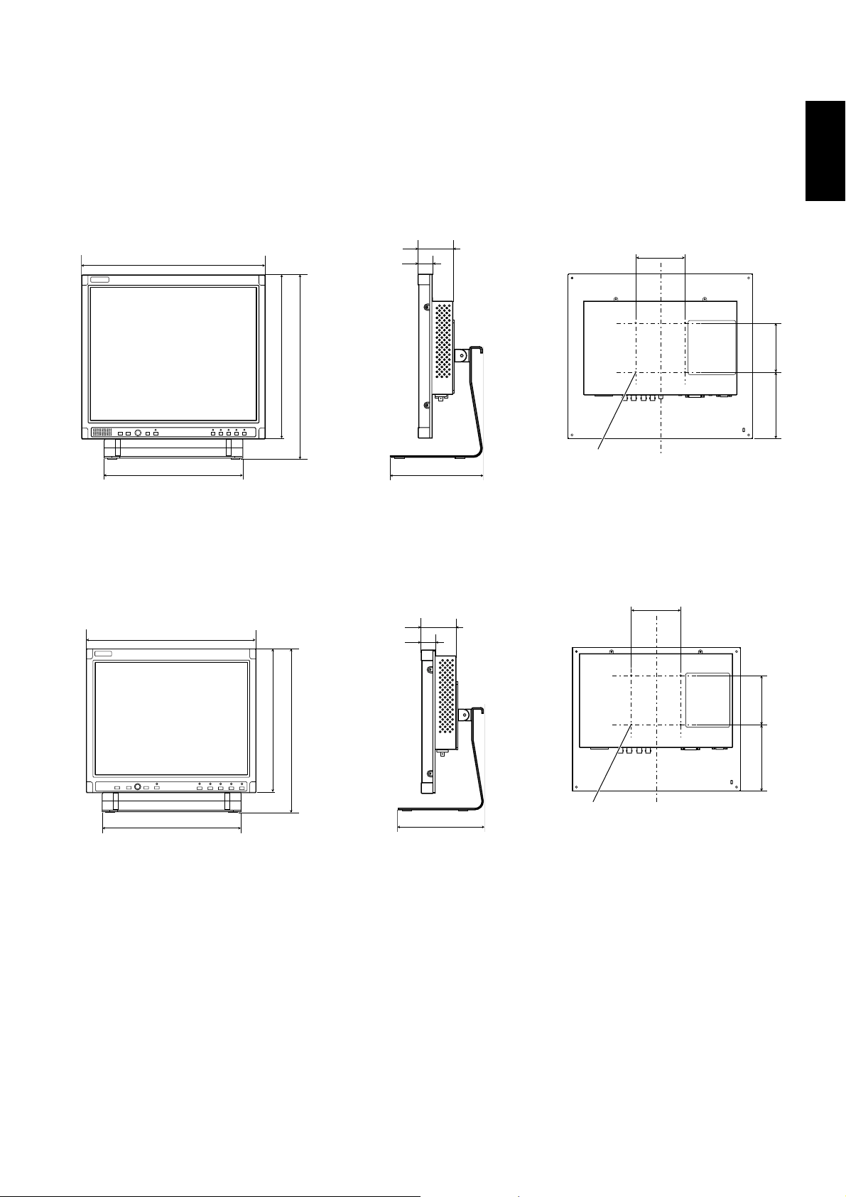
7 Dimensions
Unit : mm (inch)
LM-170A
Front View Side View Rear View (without the stand)
374 (14 3/4)
280 (11 1/8)
* at the higher position
** at the lower position
70.5 (2 7/8)
28.5 (1 1/8)
334 (13 1/4)
373.6 (14 3/4)* / 338.6 (13 3/8)**
184 (7 1/4)
VESA mounting holes
(Size: M4, depth: 10 mm)
100
LM-150A
Front View Side View Rear View (without the stand)
100
342 (13 1/2)
70.5 (2 7/8)
28.5 (1 1/8)
ENGLISH
135 (5 3/8) 100
280 (11 1/8)
* at the higher position
** at the lower position
291 (11 1/2)
330.6 (13 1/8)* / 295.6 (11 3/4)**
184 (7 1/4)
135 (5 3/8) 100
VESA mounting holes
(Size: M4, depth: 10 mm)
21
Page 24

Specifications (cont.)
Specification of the DVI-D terminal
Pin No. Input signal Pin No. Input signal Pin No. Input signal
1 8
9 16
17 24
Specification of the RGB terminal (D-sub 15-pin)
1
T.M.D.S Data 2–
2
T.M.D.S Data 2+
3
T.M.D.S Data 2/4 shield
4
NC
5
NC
6
DDC Clock
7
DDC Data
8
NC
Pin No. Input signal Pin No. Input signal
9
T.M.D.S Data 1–
10
T.M.D.S Data 1+
11
T.M.D.S Data 1/3 shield
12
NC
13
NC
14
+5 V Power
15
GND
16
Hot Plug Detect
1
Red
2
Green
3
Blue
4
—
5
GND
6
GND
7
GND
8
GND
17
18
19
20
21
22
23
24
9
10
11
12
13
14
15
External
T.M.D.S Data 0–
T.M.D.S Data 0+
T.M.D.S Data 0/5 shield
NC
NC
T.M.D.S Clock shield
T.M.D.S Clock+
T.M.D.S Clock–
+5 V
GND
GND
DDC data
Horizontal sync/
composite sync
Vertical sync
DDC clock
GND
7 Available computer signals
The following computer signals can be displayed on the monitor.
Preset signals
Signal name
VGA
SVGA
XGA
Screen
resolution
640 x 350*
640 x 480
800 x 600*
800 x 600
1024 x 768
1024 x 768*
SXGA
(LM-170A
1280 x 1024 60 Hz
only)
US TEXT
Macintosh
720 x 400* 70 Hz*
640 x 480* 67 Hz*
* Analog RGB signals only
Vertical frequency
(reflesh rate)
70 Hz*
60 Hz
56 Hz*
60 Hz
60 Hz
70 Hz*
For analog RGB signals:
In the following cases, perform “AUTO ADJ.” (+ page
13)
• When inputting other signals than those listed in
• If the picture of the listed signals is displayed in
If “AUTO ADJ.” does not solve the problem, adjust the
items in “SIZE/POSI. ADJ. (RGB).” (+ page 15)
this table
wrong position or size
22
Page 25

© 2007 Victor Company of Japan, Limited
1007MKH-MW-TU
 Loading...