

Page 1
2
V
AUTO
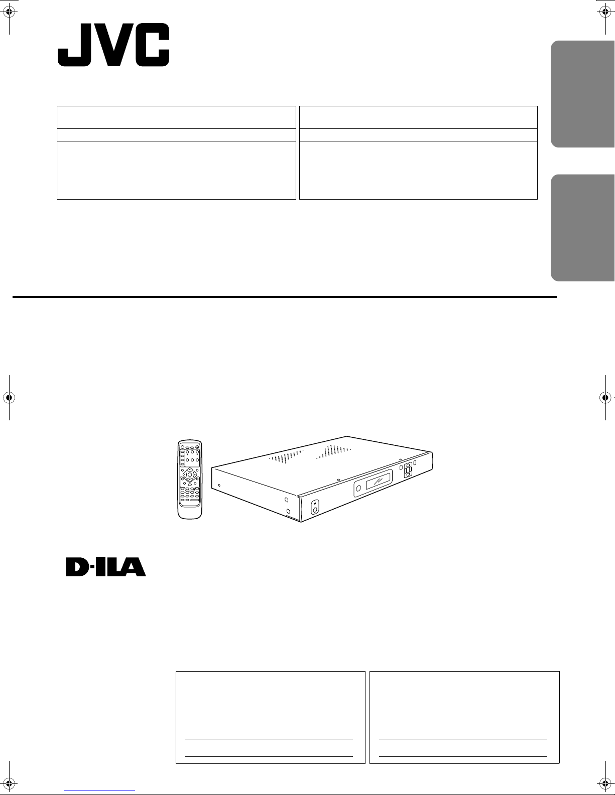
Machine Models Compatible for Connection with this
Product
DLA-HD10K Series Séries DLA-HD10K
This product (LD-HD1KU/LD-HD1KE) is exclusively for the abovementioned model. The performance cannot be guaranteed when
using with other models.
This processor is used as a dedicated machine and this manual
(instruction manual) may contain description of features as well as
specifications not used by the processor.
Ce produit (LD-HD1KU/LD-HD1KE) est compatible uniquement avec le
modèle indiqué ci-dessus. Il est impossible de garantir la performance
avec d'autres modèles.
Ce processeur doit être utilisé tel un appareil spécialisé; il est possible
que certaines des fonctions et spécifications décrites dans le présent
manuel de directives ne puissent pas être utilisées avec ce processeur.
AV HUB PROCESSOR
PROCESSEUR AV CENTRAL
Appareils compatibles pouvant être connectés à ce
produit
ENGLISHFRANÇAIS
LD-HD1KU
LD-HD1KE
STANDBY
POWER
INFO
CURTAIN
OUTPUT
SETUP
ON/OFF
TESTPATTERN
CONFIG
PICTURE
DISPLAY
VIEWING
INPUT
CONTROL
PROFILES
MODES
ASPECT
RATIO
MEMORIES
INPUT
ADJUST
MENU
EXIT
ENTER
BORDER
CROP
ZOOM PAN
ASPECT
HDMI1
4:316:9SDI
HDMI2
COMP1 S-VIDEO1 VIDEO1
HDMI3
COMP2 S-VIDEO2VIDEO
HDMI4
RGBH
INPUTSELECT
®
INSTRUCTIONS
MANUEL D’INSTRUCTIONS
For Customer use :
Enter below the serial No. which is located
on the side panel of the cabinet. Retain
this information for future reference.
Model No.
Serial No.
Pour utilisation par le client :
Entrer ci-dessous le N° de série qui est situé
sur le panneau latéral du coffret. Garder cette
information comme référence pour le futur.
LD-HD1KU LD-HD1KU
N° de modèle
N° de série
LCT1980-001A
Page 2
SAFETY PRECAUTIONS
IMPORTANT INFORMATION
WARNING: TO PREVENT FIRE OR SHOCK HAZARDS, DO NOT EXPOSE THIS APPLIANCE TO
RAIN OR MOISTURE.
CAUTION:
To reduce the risk of electric shock, do not remove cover.
Refer servicing to qualified service personnel.
This product is equipped with a 3-blade grounding type plug
to satisfy UL, CUL, TUV, FCC rules.
If you are unable to insert the plug into the outlet, contact
your electrician.
FCC INFORMATION (U.S.A. ONLY)
CAUTION:
Changes or modifications not approved by JVC could void
the user’s authority to operate the equipment.
Note: This equipment has been tested and found to comply
with the limits for a Class B digital devices, pursuant to Part
15 of the FCC Rules. These limits are designed to provide
reasonable protection against harmful interference in a residential installation. This equipment generates, uses, and can
radiate radio frequency energy and, if not installed and used
in accordance with the instructions, may cause harmful interference to radio communications.
However, there is no guarantee that interference will not
occur in a particular installation. If this equipment does cause
harmful interference to radio or television reception, which
can be determined by turning the equipment off and on, the
user is encourage to try to correct the interference by one or
more of the following measures:
- Reorient or relocate the receiving antenna.
- Increase the separation between the equipment.
- Connect the equipment into an outlet on a circuit different
from that to which the receiver is connected.
- Consult the dealer or an experienced radio/TV technician
for help.
About the installation place
Do not install the processor in a place that cannot support its
weight securely, or that does not allow for proper heat ventilation.
IMPORTANT SAFEGUARDS
IMPROPER USE OF THIS EQUIPMENT CAN
RESULT IN POTENTIAL ELECTRICAL SHOCK OR
FIRE HAZARD.
In order not to defeat the safeguards incorporated into this
product, observe the following basic rules for its installation,
use and service.
- All the safety and operating instructions should be read
before the product is operated.
- The safety and operating instructions should be followed
and retained for future reference.
- All warnings on the product and in the operating instructions should be adhered to.
- Unplug this product from the wall outlet before cleaning.
Do not use liquid cleaners or aerosol cleaners. Use a
damp cloth for cleaning.
- Do not use attachments not recommended by the product
manufacturer as they may be hazardous.
- Do not use this product near water. Do not use immediately after moving from a low temperature to high temperature, as this causes condensation, which may result in
fire, electric shock, or other hazards.
- Do not place this product on an unstable cart, stand, or
table. The product may fall, causing serious injury to a
child or adult, and serious damage to the product. The
product should be mounted according to the manufacturer’s instructions, and should use a mount recommended by the manufacturer.
- When the product is used on a cart, care should be taken
to avoid quick stops, excessive force, and uneven surfaces which may cause the product and cart to overturn,
damaging equipment or causing possible injury to the
operator.
- Slots and openings in the cabinet are provided for ventilation. These ensure reliable operation of the product and
protect it from overheating. These openings must not be
blocked or covered. (The openings should never be
blocked by placing the product on bed, sofa, rug, or similar
surface. It should not be placed in a built-in installation
such as a bookcase or rack unless proper ventilation is
provided and the manufacturer’s instructions have been
adhered to.)
- This product should be operated only with the type of
power source indicated on the label. If you are not sure of
the type of power supply to your home, consult your product dealer or local power company.
- This product is equipped with a three-wire plug. This plug
will fit only into a grounded power outlet. If you are unable
to insert the plug into the outlet, contact your electrician to
install the proper outlet. Do not defeat the safety purpose
of the grounded plug.
- Power-supply cords should be routed so that they are not
likely to be walked on or pinched by items placed upon or
against them. Pay particular attention to cords at doors,
plugs, receptacles, and the point where they exit from the
product.
- For added protection of this product during a lightning
storm, or when it is left unattended and unused for long
periods of time, unplug it from the wall outlet and disconnect the cable system. This will prevent damage to the
product due to lightning and power line surges.
2
Page 3
- Do not overload wall outlets, extension cords, or convenience receptacles on other equipment as this can result
in a risk of fire or electric shock.
- Never push objects of any kind into this product through
openings as they may touch dangerous voltage points or
short out parts that could result in a fire or electric shock.
Never spill liquid of any kind on the product.
- Do not attempt to service this product yourself as opening
or removing covers may expose you to dangerous voltages and other hazards. Refer all service to qualified service personnel.
- Unplug this product from the wall outlet and refer service
to qualified service personnel under the following conditions:
a) When the power supply cord or plug is damaged.
b) If liquid has been spilled, or objects have fallen on the
product.
c) If the product has been exposed to rain or water.
d) If the product does not operate normally by following
the operating instructions. Adjust only those controls
that are covered by the Operation Manual, as an
improper adjustment of controls may result in damage
and will often require extensive work by a qualified
technician to restore the product to normal operation.
e) If the product has been dropped or damaged in any
way.
f) When the product exhibits a distinct change in perfor-
mance – this indicates a need for service.
- When replacement parts are required, be sure the service
technician has used replacement parts specified by the
manufacturer or with same characteristics as the original
part. Unauthorized substitutions may result in fire, electric
shock, or other hazards.
- Upon completion of any service or repairs to this product,
ask the service technician to perform safety checks to
determine that the product is in proper operating condition.
- The product should be placed more than one foot away
from heat sources such as radiators, heat registers,
stoves, and other products (including amplifiers) that produce heat.
- When connecting other products such as VCR’s, and personal computers, you should turn off the power of this
product for protection against electric shock.
- Use only the accessory cord designed for this product to
prevent shock.
The power supply voltage rating of this product is AC 120 V,
AC 100 V - AC 240 V, the power cord attached conforms to
the following power supply voltage. Use only the power cord
designated by our dealer to ensure Safety and EMC. When it
is used by other power supply voltage, power cable must be
changed.
ENGLISH
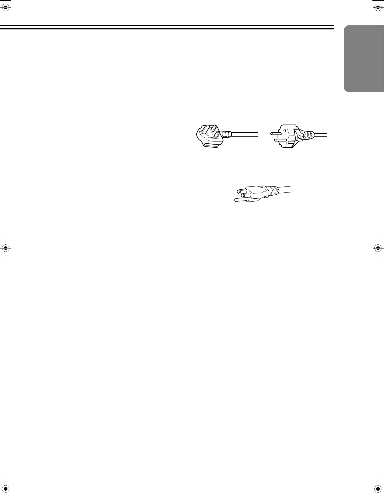
Ensure that the power cable used for the projector is the correct type for the AC outlet in your country.
Consult your product dealer.
Power cord
For United Kingdom For European continent
countries
Power cord
Power supply voltage: AC 120 V
*DO NOT allow any unqualified person to install
the unit.
Be sure to ask your dealer to install the unit since special
technical knowledge and skills are required for installation
and connection to multiple devices.
If installation is performed by an unqualified person, it may
cause personal injury or electrical shock.
Precautions for using the screen terminal
Connect the cable to the screen before using the screen terminal of this unit.
Signal with DC+12 V/100 mA max. is output from the screen
terminal of this unit.
Short-circuit will result in malfunction, fire and electric shock.
Leave the connection of the wires to the installation contrac-
tor.
3
Page 4
SAFETY PRECAUTIONS (continued)
ENGLISH
Information for Users on Disposal of Old Equipment
Attention:
This symbol is only
valid in the European
Union.
[European Union]
This symbol indicates that the electrical and electronic equipment
should not be disposed as general household waste at its end-oflife. Instead, the product should be handed over to the applicable
collection point for the recycling of electrical and electronic equipment for proper treatment, recovery and recycling in accordance
with your national legislation.
By disposing of this product correctly, you will help to conserve
natural resources and will help prevent potential negative effects
on the environment and human health which could otherwise be
caused by inappropriate waste handling of this product. For more
information about collection point and recycling of this product,
please contact your local municipal office, your household waste
disposal service or the shop where you purchased the product.
Penalties may be applicable for incorrect disposal of this waste, in
accordance with national legislation.
(Business users)
If you wish to dispose of this product, please visit our web page
www.jvc-europe.com
the product.
to obtain information about the take-back of
[Other Countries outside the European Union]
If you wish to dispose of this product, please do so in accordance
with applicable national legislation or other rules in your country
for the treatment of old electrical and electronic equipment.
DEUTSCH
Benutzerinformationen zur Entsorgung alter
Geräte
Hinweis:
Dieses Symbol ist nur
in der Europäischen
Uniongültig.
[Europäische Union]
Dieses Symbol zeigt an, dass das elektrische bzw. elektronische
Gerät nicht als normaler Haushaltsabfall entsorgt werden soll.
Stattdessen sollte das Produkt zur fachgerechten Entsorgung, Weiterverwendung und Wiederverwertung in Übereinstimmung mit der
Landesgesetzgebung einer entsprechenden Sammelstelle für das
Recycling elektrischer und elektronischer Geräte zugeführt werden.
Die korrekte Entsorgung dieses Produkts dient dem Umweltschutz
und verhindert mögliche Schäden für die Umwelt und die menschliche Gesundheit, welche durch unsachgemäße Behandlung des
Produkts auftreten können. Weitere Informationen zu Sammelstellen
und dem Recycling dieses Produkts erhalten Sie bei Ihrer
Gemeindeverwaltung, Ihrem örtlichen Entsorgungsunternehmen
oder in dem Geschäft, in dem Sie das Produkt gekauft haben.
Für die nicht fachgerechte Entsorgung dieses Abfalls können
gemäß der Landesgesetzgebung Strafen ausgesprochen werden.
(Geschäftskunden)
Wenn Sie dieses Produkt entsorgen möchten, besuchen Sie bitte
unsere Webseite www.jvc-europe.com
Rücknahme des Produkts zu erhalten.
, um Informationen zur
[Andere Länder außerhalb der Europäischen Union]
Wenn Sie dieses Produkt entsorgen möchten, halten Sie sich
dabei bitte an die entsprechenden Landesgesetze und andere
Regelungen in Ihrem Land zur Behandlung elektrischer und elektronischer Geräte.
FRANÇAIS
Informations relatives à l’élimination des appareils usagés, à l’intention des utilisateurs
Attention:
Ce symbole n’est
reconnu que dans
l’Union européenne.
[Union européenne]
Lorsque ce symbole figure sur un appareil électrique et électronique, cela signifie qu’il ne doit pas être éliminé en tant que déchet
ménager à la fin de son cycle de vie. Le produit doit être porté au
point de pré-collecte approprié au recyclage des appareils électriques et électroniques pour y subir un traitement, une récupération et un recyclage, conformément à la législation nationale.
En éliminant correctement ce produit, vous contriburez à la conservation des ressources naturelles et à la prévention des éventuels effets négatifs sur l’environnement et la santé humaine,
pouvant être dus à la manipulation inappropriée des déchets de ce
produit. Pour plus d’informations sur le point de pré-collecte et le
recyclage de ce produit, contactez votre mairie, le service d’évacuation des ordures ménagères ou le magasin dans lequel vous
avez acheté le produit.
Des amendes peuvent être infligées en cas d’élimination incorrecte de ce produit, conformément à la législation nationale.
(Utilisateurs professionnels)
Si vous souhaitez éliminer ce produit, visitez notre page Web
www.jvc-europe.com
récupération.
afin d’obtenir des informations sur sa
[Pays ne faisant pas partie de l’Union européenne]
Si vous souhaitez éliminer ce produit, faites-le conformément à la
législation nationale ou autres règles en vigueur dans votre pays
pour le traitement des appareils électriques et électroniques
usagés.
NEDERLANDS
Informatie voor gebruikers over het weggooien
van oude apparatuur
Let op:
Dit symbool is alleen
geldig in de
Europese Unie.
[Europese Unie]
Deze markering geeft aan dat de elektrische en elektronische
apparatuur bij het einde van de gebruiksduur niet bij het
huishoudelijk afval mag worden gegooid. Het product moet in
plaats daarvan worden ingeleverd bij het relevante inzamelingspunt voor hergebruik van elektrische en elektronische apparatuur, voor juiste verwerking, terugwinning en hergebruik in
overeenstemming met uw nationale wetgeving.
Door dit product naar het inzamelingspunt te brengen, werkt u
mee aan het behoud van natuurlijke hulpbronnen en met het
voorkomen van potentiële negatieve effecten op het milieu en de
volksgezondheid, die anders veroorzaakt zouden kunnen worden
door onjuiste afvalverwerking van dit product. Neem voor meer
informatie over inzamelingspunten en hergebruik van dit product
contact op met de gemeente in uw woonplaats, het afvalverwerkingsbedrijf of de winkel waar u het product hebt aangeschaft.
Er kunnen boetes gelden voor een onjuiste verwijdering van dit
afval, in overeenstemming met de nationale wetgeving.
(Zakelijke gebruikers)
Bezoek als u dit product wilt weggooien onze website www.jvceurope.com voor informatie over het terugnemen van het product.
[Landen buiten de Europese Unie]
Wanneer u dit product wilt verwijderen, houdt u dan aan de geldende nationale wetgeving of andere regels in uw land voor de
verwerking van oude elektrische en elektronische apparatuur.
4
Page 5
ESPAÑOL
PORTUGUÊS
Información para los usuarios sobre la eliminación de equipos usados
Atención:
Este símbolo sólo es
válido en la Unión
Europea.
[Unión Europea]
Este símbolo indica que los aparatos eléctricos y electrónicos no
deben desecharse junto con la basura doméstica al final de su vida
útil. El producto deberá llevarse al punto de recogida correspondiente para el reciclaje y el tratamiento adecuado de equipos eléctricos y electrónicos de conformidad con la legislación nacional.
Si desecha el producto correctamente, estará contribuyendo a
conservar los recursos naturales y a prevenir los posibles efectos
negativos en el medio ambiente y en la salud de las personas
que podría causar el tratamiento inadecuado del producto
desechado. Para obtener más información sobre el punto de recogida y el reciclaje de este producto, póngase en contacto con
su oficina municipal, su servicio de recogida de basura doméstica o la tienda en la que haya adquirido el producto.
De acuerdo con la legislación nacional, podrían aplicarse multas
por la eliminación incorrecta de estos desechos.
(Empresas)
Si desea desechar este producto, visite nuestra página Web
www.jvc-europe.com
rada del producto.
para obtener información acerca de la reti-
[Otros países no pertenecientes a la Unión
Europea]
Si desea desechar este producto, hágalo de conformidad con la
legislación nacional vigente u otras normativas de su país para el
tratamiento de equipos eléctricos y electrónicos usados.
ITALIANO
Informações para os Utilizadores sobre a Eliminação de Equipamento Antigo
Atenção:
Este símbolo apenas
é válido na União
Europeia.
[União Europeia]
Este símbolo indica que o equipamento eléctrico e electrónico
não deve ser eliminado como um resíduo doméstico geral, no fim
da respectiva vida útil. Pelo contrário, o produto deve ser
entregue num ponto de recolha apropriado, para efectuar a reciclagem de equipamento eléctrico e electrónico e aplicar o tratamento, recuperação e reciclagem adequados, de acordo com a
respectiva legislação nacional.
Ao eliminar este produto da forma correcta, ajudará a conservar
recursos naturais e ajudará a evitar potenciais efeitos negativos
no ambiente e saúde humana, que poderiam ser causados pelo
tratamento residual inadequado deste produto. Para mais informações sobre o ponto de recolha e reciclagem deste produto,
contacte a respectiva entidade local, o serviço de eliminação de
resíduos ou a loja onde adquiriu o produto.
Caso estes resíduos não sejam correctamente eliminados,
poderão ser aplicadas penalizações, em conformidade com a
respectiva legislação nacional.
(utilizadores profissionais)
Se pretender eliminar este produto, visite a nossa página da web
em www.jvc-europe.com
olução do produto.
para obter informações sobre a dev-
[Outros países fora da União Europeia]
Se pretender eliminar este produto, faça-o de acordo com a legislação nacional aplicável ou outras regras no seu país para o
tratamento de equipamento eléctrico e electrónico velho.
ΕΛΛΗΝΙΚΑ
ENGLISH
Informazioni per gli utenti sullo smaltimento
delle apparecchiature obsolete
Attenzione:
Questo simbolo è
valido solo nell'Unione
Europea.
[Unione Europea]
Questo simbolo indica che l’apparecchiatura elettrica ed elettronica
a cui è relativo non deve essere smaltita tra i rifiuti domestici generici
alla fine della sua vita utile. Il prodotto, invece, va consegnato a un
punto di raccolta appropriato per il riciclaggio di apparecchiature
elettriche ed elettroniche, per il trattamento, il recupero e il riciclaggio
corretti, in conformità alle proprie normative nazionali.
Mediante lo smaltimento corretto di questo prodotto, si contribuirà a
preservare le risorse naturali e a prevenire potenziali effetti negativi
sull'ambiente e sulla salute umana che potrebbero essere provocati,
altrimenti, da uno smaltimento inappropriato del prodotto. Per ulteriori informazioni sul punto di raccolta e il riciclaggio di questo prodotto, contattare la sede comunale locale, il servizio di smaltimento
rifiuti domestici o il negozio in cui si è acquistato il prodotto.
L’utente è responsabile del conferimento dell’apparecchio a fina
vita alle appropriate strutture di raccolta, pena le sanzioni previste dalla vigente legislazione sui rifiuti.
(Per gli utenti aziendali)
Qualora si desideri smaltire questo prodotto, visitare la nostra
pagina web
ritiro del prodotto.
www.jvc-europe.com
per ottenere informazioni sul
[Per altre nazioni al di fuori dell'Unione Europea]
Qualora si desideri smaltire questo prodotto, effettuare lo smaltimento in conformità alla normativa nazionale applicabile o alle
altre leggi della propria nazione relative al trattamento delle
apparecchiature elettriche ed elettroniche obsolete.
Πληροφορίες σχετικά µε την απόρριψη
εξοπλισµού
Προσοχή:
Αυτή η σήµανση ισχύει
µόνο για την
Ευρωπαϊκή Ένωση.
[Ευρωπαϊκή Ένωση]
Αυτή η σήµανση υποδηλώνει ότι ο ηλεκτρικός και ηλεκτρονικός
εξοπλισµός δεν πρέπει να απορριφθεί ως κοινό οικιακό
απόρριµµα. Αντ' αυτού, το προϊόν πρέπει να παραδοθεί στο
ανάλογο σηµείο περισυλλογής για την ανακύκλωση των
ηλεκτρικών και ηλεκτρονικών µερών και την κατάλληλη
επεξεργασία, σύµφωνα µε τη νοµοθεσία της ώρας σας.
Η σωστή απόρριψη αυτού το προϊόντος βοηθάει στη διαφύλαξη
των φυσικών πόρων και στην αποφυγή αρνητικών επιπτώσεων
στο περιβάλλον και στην ανθρώπινη υγεία, κάτι που ενδέχεται να
προκληθεί από την ακατάλληλη διαχείριση αυτού του προϊόντος
ως απρριµµα. Για περισσότερες πληροφορίες σχετικά µε τα
σηµεία περισυλλογής και ανακύκλωσης αυτού του προϊόντος,
επικοινωνήστε µε τα γραφεία της τοπικής αυτοδιοίκησης, την
υπηρεσία περισυλλογής απορριµµάτων ή το κατάστηµα από το
οποίο αγοράσατε το προϊόν.
Ανάλογα µε τη νοµοθεσία της χώρας σας, ενδέχεται να
επιβληθούν κυρώσεις σε περίπτωση λανθασµένης απόρριψης
αυτού του προόϊντος.
(Επιχειρήσεις)
Αν επιθυµείτε να απορρίψετε αυτό το προϊόν, επισκεφτείτε το
διαδικτυακό µας τόπο www.jvc-europe.com
πληροφορίες σχετικά µε την επιστροφή του προϊόντος.
για περισσότερες
[Άλλες χώρες εκτός Ευρωπαϊκής Ένωσης]
Αν επιθυµείτε να απορρίψετε αυτό το προϊόν, πρέπει να
τηρήσετε την ισχύουσα εθνική νοµοθεσία ή όποιους άλλους
κανονισµούς για τη χώρα σας για την απόρριψη ηλεκτρικού και
ηλεκτρονικού εξοπλισµού.
5
Page 6
SAFETY PRECAUTIONS (continued)
DANSK
Brugerinformation om bortskaffelse af gammelt
udstyr
Bemærk:
Dette symbol er kun
gyldigt i EU.
[EU]
Elektriske produkter og elektroniske apparater med dette symbol
må ikke afhændes på samme måde som almindeligt husholdningsaffald, når det skal smides ud. I stedet skal produktet indleveres på det relevante indsamlingssted for elektriske apparater
og elektronisk udstyr, hvor det vil blive håndteret korrekt og efterfølgende genanvendt og recirkuleret i henhold til de love, der
gælder i dit land.
Ved at bortskaffe dette produkt korrekt, medvirker du til at bevare
naturens ressourcer samt forhindre eventuelle negative
påvirkninger af miljøet og folkesundheden, der ellers kunne forårsages ved forkert affaldshåndtering af dette produkt. Mere information om indsamlingssteder og genanvendelse af dette produkt
kan du få ved at kontakte din lokale kommune, dit renovationsselskab eller den forretning, hvor du har købt produktet.
Ukorrekt bortskaffelse af dette affald kan være strafbar ifølge lovgivningen i nogle lande.
(Professionelle brugere)
Hvis du ønsker at bortskaffe dette produkt, kan du på vores webside www.jvc-europe.com
produktet.
få information om tilbagetagning af
[Lande uden for EU]
Hvis du ønsker at bortskaffe dette produkt, bedes du gøre det i
overensstemmelse med gældende lovgivning eller andre regler i
dit land for behandling af gammelt elektrisk og elektronisk udstyr.
SUOMI
Tietoja käyttäjille vanhojen laitteiden hävittämisestä
Huomio:
Tämä symboli on voimassa vain Euroopan
unionissa.
[Euroopan unioni]
Tämä symboli tarkoittaa, että sähkö- ja elektroniikkalaitteita ei
tule laittaa talousjätteisiin, kun ne poistetaan käytöstä. Sen sijaan
tuotteet tulee toimittaa asianmukaiseen sähkö- ja elektroniikkalaitteiden kierrätyspisteeseen, jossa ne käsitellään
uusiokäyttöä ja kierrätystä varten paikallisen lainsäädännön
mukaan.
Kun hävität tuotteen asianmukaisella tavalla, autat säästämään
luonnonvaroja ja estämään mahdollisia ympäristö- ja terveyshaittoja, joita voisi aiheutua tämän tuotteen vääränlaisesta hävittämisestä. Lisätietoja keräyspisteistä ja tämän tuotteen
kierrätyksestä saat paikkakuntasi viranomaisilta, kotitalousjätteiden keräyksestä huolehtivasta yrityksestä tai liikkeestä, josta
ostit tuotteen.
Tuotteen vääränlaisesta hävittämisestä voi seurata paikallisen
lainsäädännön mukaisia rangaistuksia.
(Yrityskäyttäjät)
Jos haluat hävittää tämän tuotteen, web-sivustoltamme osoitteessa www.jvc-europe.com
palautuksesta.
löydät tietoja käytetyn tuotteen
[Muut maat Euroopan unionin ulkopuolella]
Jos haluat hävittää tämän tuotteen, tee se kansallisen lainsäädännön tai muiden maassasi voimassa olevien määräysten
mukaan, jotka koskevat vanhojen sähkö- ja elektroniikkalaitteiden käsittelyä.
SVENSKA
Information till användare gällande kassering av
gammal utrustning
Tänk på:
Att denna symbol
endast gäller inom den
Europeiska
gemenskapen.
[Europeiska gemenskapen]
Denna symbol anger att elektrisk och elektronisk utrustning inte
ska kasseras som vanligt hushållsavfall, när de inte ska användas mer. Istället ska produkten lämnas in på lämplig återvinningsstation för elektrisk eller elektronisk utrustning, så att den
kan tas om hand och återvinnas i enlighet med ert lands lagstiftning.
Genom att avyttra denna profukt på rätt sätt, bidrar du till att bevara naturen och förhindrar potentiellt negativa effekter på miljön
och den mänskiliga hälsan, som annars kan bli resultatet vid
felaktig hantering av denna produkt. Kontakta ditt kommunkontor,
det företag som hanterar dina hushållssopor eller butiken där du
köpt produkten, för mer information om återvinningscentraler.
Det kan hända att du bötfälls i enlighet med ert lands lagstiftning
om detta avfall kasseras på fel sätt.
(Företagsanvändare)
Om ni vill kassera denna produkt, besök vår webbsida www.jvceurope.com för att få information om returnering av produkten.
[Övriga länder utanför den Europeiska
gemenskapen]
Om du vill kassera denna produkt, ska detta göras i enlighet med
gällande lagstiftning i landet, eller enligt andra bestämmelser i
ditt land, för behandling av gammal elektrisk eller elektronisk
utrustning.
NORSK
Informasjon til brukerne om kassering av gammelt utstyr
OBS!
Dette symbolet er kun
gyldig i den Europeiske
Union og i EFTA-landene
Norge, Island og Sveits.
[Europeiske Union]
Dette symbolet betyr at det elektriske eller elektroniske utstyret
ikke skal kasseres som vanlig husholdningsavfall når det har
nådd slutten av sin levetid. I stedet skal produktet leveres til en
passende mottaksstasjon for kasserte elektriske og elektroniske
produkter, slik at disse kan behandles, gjenvinnes og resirkuleres
i samsvar med nasjonal lovgivning.
Hvis du kasserer dette produktet på riktig måte, bidrar til du til å
bevare naturlige ressurser og til å motvirke de negative virkningene på miljøet og den menneskelige helse som kan oppstå hvis
produktet kasseres på feil måte. Hvis du vil ha mer informasjon
om mottaksstasjoner og gjennvinning av dette produktet, kan du
ta kontakt med kommunen din, renovasjosselskapet ditt eller den
forhandleren du kjøpte produktet av.
Feilaktig kassering av dette utstyret kan kanskje bøtelegges,
avhengig av nasjonale lover og regler.
(Bedriftsbrukere)
Hvis du ønsker å kassere dette produktet, kan du gå til hjemmesiden vår på www.jvc-europe.com
informasjon om retur av dette produktet.
eller www.elretur.no for å få
[Andre land utenfor EU]
Hvis du ønsker å kassere dette produktet, må du gjøre det i
samsvar med gjeldende nasjonal lovgivning eller andre regler
som gjelder i landet ditt når det gjelder behandling av gammelt
elektrisk og elektronisk utstyr.
6
Page 7
РУССКИЙ
Информация для пользователей,
выбрасывающих старое оборудование
Внимание:
Действие этого символа
распространяется
только на Европейский
Союз.
[Европейский Союз]
Это символ указывает, что после окончания срока службы
соответствующего электрического или электронного
оборудования, нельзя выбрасывать его вместе с обычным
бытовым мусором. Вместо этого, оно подлежит сдаче на
утилизацию в соответствующий пункт приема
электрического и электронного оборудования для
последующей переработки и утилизации в соответствии с
национальным законодательством.
Обеспечивая правильную утилизацию данного продукта, Вы
помогаете сберечь природные ресурсы и предотвращаете
ущерб для окружающей среды и здоровья людей, который
возможен в случае ненадлежащего обращения. Более
подробную информацию о пунктах приема и утилизации
данного продукта можно получить в местных
муниципальных органах, на предприятии по вывозу
бытового мусора или по месту приобретения продукта.
Нарушение правил утилизации данного типа отходов в
соответствии с национальным законодательством является
административным правонарушением.
(Организации-пользователи)
Прежде чем выбрасывать данный продукт, ознакомьтесь с
информацией о приемке отработавших продуктов,
приведенной на веб-узле www.jvc-europe.com
.
[Страны, не входящие в Европейский Союз]
Если Вы собираетесь выбросить данный продукт,
руководствуйтесь национальным законодательством или
другими правилами, действующими в Вашей стране по
отношению к переработке старого электрического и
электронного оборудования.
ENGLISH
7
Page 8

TABLE OF CONTENTS
SAFETY PRECAUTIONS...................................................................................................................................... 2
TABLE OF CONTENTS ........................................................................................................................................ 8
Accessories/Controls and Features................................................................................................................... 9
Accessories...........................................................................................................................................................................9
FRONT..................................................................................................................................................................................9
REAR ..................................................................................................................................................................................10
Remote Control...................................................................................................................................................................12
Installation and Connection .............................................................................................................................. 15
Precautions for Installation..................................................................................................................................................15
Connecting to Devices ........................................................................................................................................................16
Turning on the power ..........................................................................................................................................................17
Basic Operation Procedures............................................................................................................................. 18
Setting the Output ...............................................................................................................................................................18
Screen (Onscreen) Display and Operation .........................................................................................................................19
Adjustments and Settings Using Menus ......................................................................................................... 20
Menu List.............................................................................................................................................................................20
Menu Configuration.............................................................................................................................................................20
Specifications..................................................................................................................................................... 26
Memo................................................................................................................................................................... 27
8
Page 9
Accessories/Controls and Features
Accessories
The following accessories are packed together with this unit. Please confirm all items.
If any item is missing, please contact your dealer.
Instructions.............................................................................................................................................................x 1
Guarantee ...............................................................................................................................................................x 1
Power Cord (LD-HD1KU) .......................................................................................................................................x 1
(LD-HD1KE) .........................................................................x 1 (for European continental countries)
(LD-HD1KE) ...................................................................................................x 1 (for United Kingdom)
AC Adapter .............................................................................................................................................................x 1
HDMI-DVI Cable.....................................................................................................................................................x 1
Remote Control ......................................................................................................................................................x 1
AAA size Batteries (for operation confirmation).................................................................................................x 2
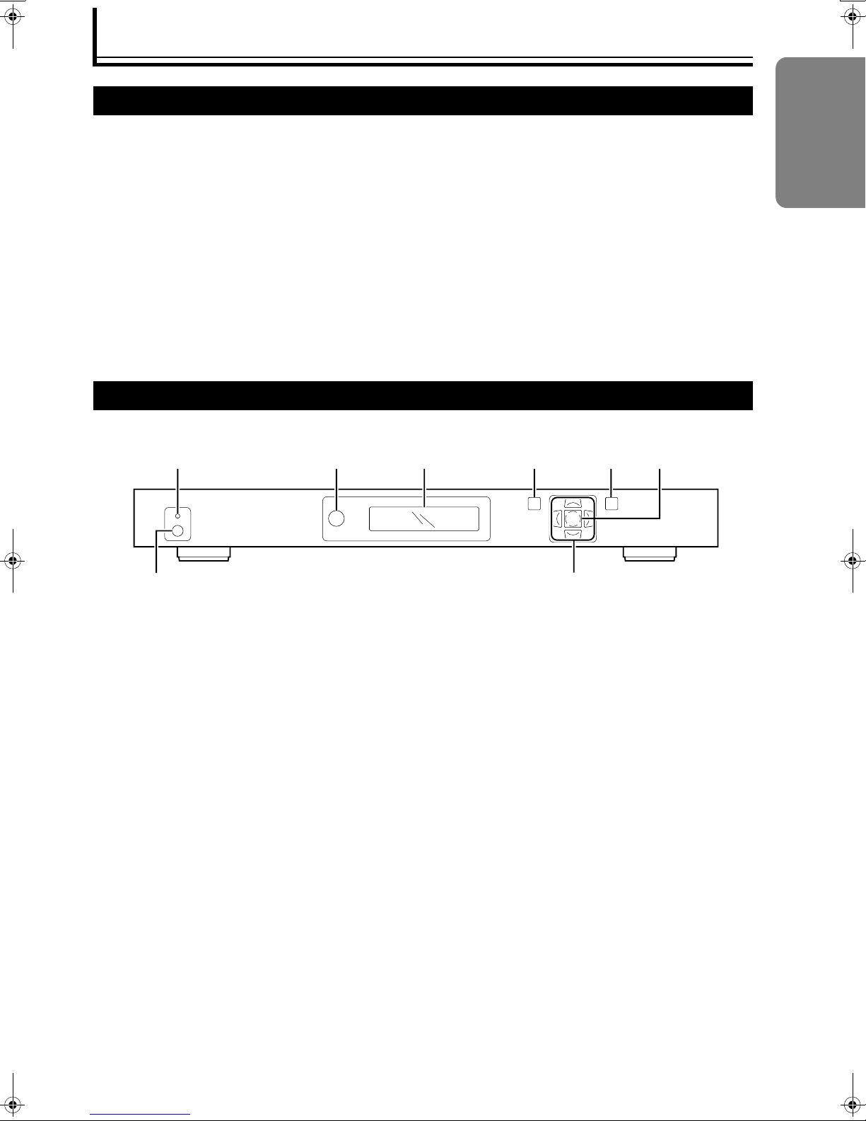
FRONT
ENGLISH
ABCDEF
GH
A Status LED
Light off:
Unit is in standby mode.
Red:
No device is connected to the selected input terminal.
The cable is connected to the selected input terminal
but there is no input signal.
NInput the signals to the selected input terminal.
Blue:
Signals are input while in operation.
Green:
A signal that cannot be used with this unit has been
input.
NInput a signal that can be used with this unit.
(A Page 11)
B Remote Control Sensor Window
When operating with the remote control, aim it
towards the sensor.
C LCD
Displays the menu items and information of this
processor.
D [MENU] Button
Press to change the settings of this processor. Press
again to exit the setting mode. (Display on the
processor and the menu disappear.)
E [EXIT] Button
Press to return to the previous menu.
The menu will disappear when there is none to return
to.
F [ENTER] Button
Press this to confirm the selected item in the menu.
G Power/Standby Button
Press to turn the unit On when it is in the standby
mode. Press again to switch to the standby mode.
H [J / K / H / I] (Navigation) Buttons
Press these buttons to move the cursor from one
menu item to another.
Use the [H/I] buttons to switch the input source.
9
Page 10

Accessories/Controls and Features (continued)
REAR
ABCDEFGHI
SDI
INPUT
OUTPUT INTPUT
1234
I
N
P
U
T
O
U
T
P
U
T
ANALOG VIDEOHDMI
(R)
Pb
(B)
Y
(G)
A [SDI INPUT] Terminal
Not used.
B [ANALOG VIDEO INPUT] Terminal
(Y(G), Pb(B), Pr(R), H and V BNC Terminals)
For input of color difference component signals and
analog RGB signals.
C [SYNC INPUT 1/2] Terminal (RCA Terminal)
For sending RGB signal input to the [COMPONENT
INPUT 1/2] terminal as synchronous signals.
D [COMPONENT INPUT 1/2] Terminal
(Y(G), Pb(B) and Pr(R) RCA Terminal)
For input of color difference component signals and
analog RGB signals.
E [S-VIDEO INPUT 1/2] Terminal (Mini DIN 4 Pin)
For input of S-video (Y/C) signals of sources such as
video decks.
F [VIDEO INPUT 1/2] Terminal (RCA Terminal)
For input of composite video signals of sources such
as video decks.
VHPr
DC In
I
N
+6V @5A
P
U
T
2
S
POWER
Pb
(B)Pr(R)
Y
(G)
121
1
1
2
2
21
ANALOG AUDIO INPUTINPUTOUTPUT
43
G [DIGITAL AUDIO OUTPUT] Terminal
(Optical/Coaxial Terminal)
For output of digital audio signals.
H [DIGITAL AUDIO INPUT 1/2] Terminal (Optical
Terminal)
[DIGITAL AUDIO INPUT 3/4] Terminal (Coaxial
RCA Terminal)
For input of digital audio signals of sources such as
DVD players.
I [ANALOG AUDIO INPUT L/R] Terminal (RCA
Terminal)
For input of analog audio output signals of sources
such as video decks.
J [HDMI OUTPUT] Terminal
For output of HDCP-compliant digital video signals.
K [HDMI INPUT 1/2/3/4] Terminal
For input of HDCP-compliant digital video signals of
sources such as DVD recorders.
L [ANALOG VIDEO OUTPUT] Terminal
This is an analog signal output. Use this for
connecting to a display device with an input terminal
for RGBHV or YPbPr signals.
● Not normally used.
LR
SERIAL PORTDIGITAL AUDIOVIDEOS-VIDEOCOMPONENTSYNC
NMLKJ
10
M [POWER] Terminal (DC IN +6 V)
Connect the supplied AC adapter to this terminal.
(A Page 17)
N [SERIAL PORT] Terminal (Dsub 9 Pin)
Not used.
Page 11

Signals corresponding to each terminal are listed in the table below.
Input Terminal Input Signal
Video
VIDEO INPUT 1/2
S-VIDEO INPUT 1/2
COMPONENT INPUT 1/2
SYNC INPUT 1/2
ANALOG VIDEO INPUT
HDMI INPUT 1/2/3/4
Audio
DIGITAL AUDIO INPUT 1/2
(Optical Digital)
DIGITAL AUDIO INPUT 3/4
(Coaxial Digital)
HDMI INPUT 1/2/3/4 Compliant with HDMI audio format
Output Terminal Output Signal
Video
ANALOG VIDEO OUTPUT
HDMI OUTPUT
Audio
DIGITAL AUDIO OUTPUT Same as audio input signals
HDMI OUTPUT Compliant with HDMI audio format
NT S C, PA L, PAL - M, SE C AM
480i, 480p, 576i, 576p, 720p/50 Hz, 720p/60 Hz, 1080i/50 Hz, 1080i/60 Hz
(YPbPr/RGBS)
480p, 576p, 720p/50 Hz, 720p/60 Hz, 1080i/50 Hz, 1080i/60 Hz
(YPbPr/RGBHV)
480i, 480p, 576i, 576p, 720p/50 Hz, 720p/60 Hz, 1080i/50 Hz, 1080i/60 Hz
(RGB/YCbCr 4:4:4/YCbCr 4:2:2)
24bit/24 kHz-96 kHz
24bit/24 kHz-192 kHz
YPbPr, RGBHV, RGB (Sync on G), RGBS (Sync from H)
(Refer to AFormatB of AOUTPUT SETUPB for details on resolution) (A Page 23)
RGB 4:4:4 (8bit), YCBCr 4:4:4 (8bit), YCbCr 4:2:2 (10bit)
(Refer to AFormatB of AOUTPUT SETUPB for details on resolution) (A Page 23)
ENGLISH
11
Page 12

Accessories/Controls and Features (continued)
2
V
AUTO
Remote Control
Some buttons may not function depending on your input source or unit’s settings.
C Submenu Button
A
B
C
D
E
F
G
STANDBY
INFO
OUTPUT
SETUP
TEST PATTERN
CONFIG
PICTURE
DISPLAY
CONTROL
PROFILES
INPUT
ADJUST
MENU
ENTER
BORDER
ZOOM PA N
ASPECT
HDMI 1
4:316:9SDI
HDMI 2
COMP 1 S-VIDEO 1 VIDEO 1
HDMI 3
COMP 2 S-VIDEO2VIDEO
HDMI 4
RGBH
INPUT SELECT
CURTAIN
ON/OFF
VIEWING
MODES
MEMORIES
POWER
INPUT
ASPECT
RATIO
EXIT
CROP
H
I
J
K
L
M
N
O
P
Q
R
[OUTPUT SETUP] Button
Displays items in the AOUTPUT SETUPB menu.
Press this button to move the cursor from one item to
another. (A Page 23)
[CONFIG] Button
Displays items in the ACONFIGURATIONB menu.
Press this button to move the cursor from one item to
another. (A Page 22)
[PICTURE CONTROL] Button
Displays items in the APICTURE CONTROLB menu.
Press this button to move the cursor from one item to
another. (A Page 22)
[INPUT ADJUST] Button
Displays items in the AINPUT ADJUSTB menu. Press
this button to move the cursor from one item to
another. (A Page 21)
D [MENU] Button
Press to change the settings of this processor. Press
again to exit the setting mode. (Display on the
processor and the menu disappear.)(A Page 20)
A [INFO] Button
Displays items in the AInformationB menu of the
ACONFIGURATIONB menu. (A Page 23)
B [STANDBY] Button
Press this to switch to the standby mode when the
power of this unit is turned On.
E [BORDER] Button
Displays items in the ABordersB menu of the AINPUT
ASP. RATIOB menu. (A Page 21)
F [ZOOM] Button
Displays items in the AZoomB menu of the AINPUT
ASP. RATIOB menu. (A Page 20)
G Aspect Button
[ASPECT] Button
Displays items in the AINPUT ASP. RATIOB menu.
Press this button to move the cursor from one item to
another. (A Page 20)
[4:3] Button
Sets APresetB of the AINPUT ASP. RATIOB menu to
A4:3 F.FrameB. (A Page 21)
[16:9] Button
Sets APresetB of the AINPUT ASP. RATIOB menu to
A16:9 F.FrameB. (A Page 21)
12
Page 13

H [CURTAIN] Button
Press this button to temporarily hide the video image.
I [POWER] Button
Press to turn the unit On when it is in the standby
mode.
J Test Pattern Button
[ON/OFF] Button
Displays the test pattern or turns off the display.
[H] and [I] Buttons
Switches the test pattern.
K [VIEWING MODE] Button
Not used.
L [INPUT ASPECT RATIO] Button
Displays the APresetB items in the AINPUT ASP.
RATIOB menu. (A Page 21)
M [DISPLAY PROFILE] Button
Displays the ADisplay ProfileB items in the AOUTPUT
SETUPB menu. (A Page 25)
N [EXIT] Button
Press to return to the previous menu. The menu will
disappear when there is none to return to.
O [J / K / H / I] and [ENTER] Buttons
Use these buttons to operate the menu.
P [CROP] Button
Not used.
Q [PAN] Button
Displays items in the APanB menu of the AINPUT
ASP. RATIOB menu. (A Page 20)
R Buttons for Direct Input Selection
[HDMI 1] Button
Switches to the image from the [HDMI INPUT 1]
terminal.
[HDMI 2] Button
Switches to the image from the [HDMI INPUT 2]
terminal.
[HDMI 3] Button
Switches to the image from the [HDMI INPUT 3]
terminal.
[HDMI 4] Button
Switches to the image from the [HDMI INPUT 4]
terminal.
[COMP 1] Button
Switches to the image from the [COMPONENT
INPUT 1] terminal.
[COMP 2] Button
Switches to the image from the [COMPONENT
INPUT 2] terminal.
[RGBHV] Button
Switches to the image from the [ANALOG VIDEO
INPUT] terminal (BNC terminal).
[S-VIDEO 1] Button
Switches to the image from the [S-VIDEO INPUT 1]
terminal.
[S-VIDEO 2] Button
Switches to the image from the [S-VIDEO INPUT 2]
terminal.
[SDI] Button
Switches to the image from the [SDI INPUT] terminal.
(Not used)
[VIDEO 1] Button
Switches to the image from the [VIDEO INPUT 1]
terminal.
[VIDEO 2] Button
Switches to the image from the [VIDEO INPUT 2]
terminal.
[AUTO] Button
Automatically differentiates the input signals and
switches to the input terminal’s image.
ENGLISH
13
Page 14

Accessories/Controls and Features (continued)
Load batteries into the remote control. If the remote control starts to function erratically, replace the batteries with new
ones.
a Open the back cover
To open, push the top of the back cover towards you.
b Load the batteries
Insert the 2 (AAA) batteries supplied according to the
F, G marks. To prevent short circuit, be sure to insert
the G (minus) end of the battery first.
Precautions for Using Batteries
If batteries are incorrectly used, they may crack or
leak. This could cause fire, burn, malfunction, and
staining or damaging of the surroundings.
Beware of the following:
● Do not mix new and old batteries.
● Do not mix different type of batteries as they are
different in characteristics.
● Insert batteries according to the F and G marks on the
battery case.
● Be sure to insert the G end in first to prevent short
circuit.
● Do not put batteries into fire or recharge them.
● Use only designated batteries.
● Remove the batteries if the remote control is not to be
used for a prolonged period.
● Use manganese batteries wherever possible. Do not
use rechargeable or alkaline batteries.
● Read the safety precautions displayed on the batteries.
c Close the back cover
To close, fit the tab of the back cover into the groove of
the remote control.
Battery Life
Batteries last for 6 months to 1 year under normal use.
However, batteries provided are for confirming operation
and may not last that long.
Battery Leakage
When the batteries are totally exhausted and can no
longer be used, replace them immediately.
Leaving the batteries in the battery compartment causes
leakage, which may in turn lead to malfunction.
14
Page 15

Installation and Connection
Precautions for Installation
Please read the following carefully when installing this unit.
Installation Environment
This unit is a precision device. Do not install it at the following places. Doing so may cause fire or malfunction of
the unit.
● Where there is water, humidity or dust
● Where the unit may be subjected to oily or cigarette smoke
● On a soft surface such as carpet or cushion
● Where the unit may be subjected to high temperature due to direct sunlight
● When temperature is high or low
Check that it is well ventilated before installing on a rack. When devices that emit heat, such as power amplifiers, are to
be installed on a rack, mount a fan on the rack as well.
Allowable operation temperature range: +5 I to +35 I
Allowable relative humidity range: 20 % to 80 % (no condensation)
Allowable storage temperature range: -10 I to +60 I
Minimum Space Required
30 mm and above
100 mm and above 30 mm and above
● Do not place this unit in an enclosed area or block the
air vents. Allow sufficient space around this unit for
emission of heat.
● The unit’s air vents are at the top and bottom.
● Do not place objects on top of this unit when electricity
is flowing.
ENGLISH
100 mm and above
100 mm and above
15
Page 16

Installation and Connection (continued)
SERIALPORTDIGITAL AUDIOVIDEOS-VIDEOCOMPONENTSYNC
POWER
ANALOG VIDEOHDMI
ANALOG AUDIOINPUTINPUTOUTPUT
LR
21
1
2
121
2
1
2
43
Pb
(B)Pr(R)
Y
(G)
VHPr
(R)
Pb
(B)
Y
(G)
I
N
P
U
T
S
I
N
P
U
T
O
U
T
P
U
T
OUTPUT INTPUT
1234
SDI
INPUT
DCIn
+6V@5A
SERIALPORTDIGITAL AUDIOVIDEOS-VIDEOCOMPONENTSYNC
POWER
ANALOG VIDEOHDMI
ANALOG AUDIOINPUTINPUTOUTPUT
LR
21
1
2
121
2
1
2
43
Pb
(B)Pr(R)
Y
(G)
VHPr
(R)
Pb
(B)
Y
(G)
I
N
P
U
T
S
I
N
P
U
T
O
U
T
P
U
T
OUTPUT INTPUT
1234
SDI
INPUT
DCIn
+6V@5A
Connecting to Devices
Before connection, be sure to turn off both this unit and the device to be connected.
Connecting to Input Devices
● Exclusive connection cables and adapters may be required for the connection of some devices. Refer to the instruction
manual on the device to be connected for details.
● See below for an illustration of the devices used and method of connection.
HDD/DVD Recorder,
Video Deck, etc.
Digital Tuner, etc.
Digital Audio (Optical/Coaxial)
HDMI
Component Video
Video/S-Video
Analog Audio
Rear View
Connecting to the Projector and Amplifier
● Read the manual that is supplied with the projector to be connected thoroughly.
● Use the HDMI-DVI cable supplied with this unit. The use of a split system or optical fiber cable is recommended when
using a cable longer than that supplied.
● Depending on the capability of the cable used, signals may attenuate or video images may become unstable.
Rear View
HDMIYDVI-D
(Supplied)
DLA-HD10KU/E Series
16
Digital Audio
(Optical/Coaxial)
AV Amplifier, etc.
Page 17

Turning on the power
Before plugging in the power cord, ensure that all devices have been connected.
c
a Connect the AC adapter output cord to the [DC In]
ENGLISH
terminal of this unit.
b Attach the power cord to the AC adapter
a
b
c Insert the power cord into the power outlet
● The following message is displayed on the LCD for about 3 seconds.
JVC LD-HD1K
Powered by ABT
Perform the following procedures to switch this unit to the operating mode
if the Status LED does not light up.
d Turn on the power by pressing the Power/Standby
button on this unit
● The Status LED lights up in red.
e Turn on the power of the input source.
f Press the [H/I] buttons to select the input source
fd
● The Status LED lights up in blue when signals are detected.
Precautions Against Fire and Electric Shock
● When not using devices, remove the power plug from the wall outlet.
● Do not use power cords for connection other than those supplied.
● Do not use AC adapters for connection other than those supplied.
● Do not use a power voltage different from that which is indicated.
● Do not cut, tear or modify the power cords. Also, do not place a heavy object on, heat or stretch the power cords as this
may cause damage to the cords.
● Do not modify or disassemble the AC adapter.
● Do not use the supplied AC adapter on other devices.
● Do not insert or pull out plugs with a wet hand.
● Do not allow dirt or metal to adhere to the power plug.
● When the electricity is turned on, do not cover the AC adapter with a rug or place it near equipment emitting heat, such
as heaters.
● Do not use with the power plug and AC adapter, or the AC adapter and this unit not properly connected.
● Be sure to plug the power plug firmly into the outlet.
17
Page 18

Basic Operation Procedures
Setting the Output
The factory settings of this unit are as follows.
● Input terminal selection: Auto (Detects input signals sent to the input terminal automatically.)
● Output terminal selection: HDMI (Digital) (Outputs as RGB 4:4:4 signals.)
Follow the procedures below to set the output if the screen does not appear when in the default state.
● It may take a while to display the screen upon input of a HDCP signal.
Set using the remote control or buttons at the front of this unit while monitoring the LCD.
Remote control Buttons on this unit
MENU
EXIT
ENTER
BORDER
● Press the [EXIT] button when an erratic operation is performed. Alternatively, press the [MENU] button to exit the menu,
then you will be able to repeat the operation from the beginning.
a Press the [MENU] button.
● The menu appears on the LCD.
CROP
g Press the [K] button.
OUTPUT SETUP
MAIN MENU
Format
INPUT SELECT
h Press the [ENTER] button.
b Press the [J] button.
Format
MAIN MENU
420p
OUTPUT SETUP
i Press the [K] button a few times to
c Press the [ENTER] button.
OUTPUT SETUP
Analog/Digital
d Press the [ENTER] button.
select A1080p-60B or A1080p-50B.
● Select A1080p-60B when the input signal is NTSC.
● Select A1080p-50B when the input signal is PAL/
SECAM.
Format
1080p-60
Analog/Digital
BNC (Analog)
e Press the [K] button to select AHDMI
(Digital)B.
Analog/Digital
HDMI (Digital)
f Press the [ENTER] button.
OUTPUT SETUP
Analog/Digital
18
jPress the [ENTER] button to confirm
selection.
k Press the [MENU] button to end the
setting.
● The display on the LCD disappears.
(The processor exits the setting mode automatically
and the display disappears when no operation is
performed for about 30 seconds.
Page 19

Screen (Onscreen) Display and Operation
As the menu is displayed on top of the video image, it is possible to check the image while altering the settings. If the
video image disappears, restore the original settings while monitoring the LCD.
ENGLISH
INPUT SELECT
INPUT ASP.RATIO
INPUT ADJUST
PICTURE CONTROL
CONFIGURATION
OUTPUT SETUP
INPUT SELECT
INPUT ASP.RATIO
INPUT ADJUST
PICTURE CONTROL
CONFIGURATION
OUTPUT SETUP
Analog/Digital
Format
Aspect Ratio
Sync Type
Color Space
Framerate
Color Depth
Display Profile
INPUT SELECT
INPUT ASP.RATIO
INPUT ADJUST
PICTURE CONTROL
CONFIGURATION
OUTPUT SETUP
Analog/Digital
Format
Aspect Ratio
Sync Type
Color Space
Framerate
Color Depth
Display Profile
BNC(Analog
HDNI(Digital
Press the [MENU] button to display the menu.
Press the [MENU] button again to clear the menu.
The menu can also be cleared by pressing the [EXIT] button.
The left diagram shows an example where AOUTPUT SETUPB is selected.
Press the [ENTER] or [I] button to display the submenu.
Press the [ENTER] or [I] button to display the next submenu.
Press the [J] or [K] button to alter the set value.
)
)
INPUT SELECT
INPUT ASP.RATIO
INPUT ADJUST
PICTURE CONTROL
CONFIGURATION
OUTPUT SETUP
Analog/Digital
Format
Aspect Ratio
Sync Type
Color Space
Framerate
Color Depth
Display Profile
INPUT SELECT
INPUT ASP.RATIO
INPUT ADJUST
PICTURE CONTROL
CONFIGURATION
OUTPUT SETUP
Analog/Digital
Format
Aspect Ratio
Sync Type
Color Space
Framerate
Color Depth
Display Profile
Display
Screen
Shift
Underscan
Display 4:3
2.35:1
User
A more detailed submenu is available for submenu items with a I on its right.
To return to the previous menu, press the [EXIT] or [H] button.
To exit the menu display, press the [MENU] button.
5:4
16:9
19
Page 20

Adjustments and Settings Using Menus
.
.
The menus of this unit form a structure as shown below.
The menu is displayed on the LCD as well as the screen through the projector that is connected to this unit.
Menu List Menu Configuration
INPUT SELECT
INPUT ASP. RATIO
Frame AR
Active Input AR
Zoom
Pan
Borders
Preset
Save
INPUT ADJUST
Border Level
Overscan
Line Offset
HDMI Input Control
VCR Mode
Film Mode
Auto Priority
Audio Input
AV Lip Sync
PICTURE CONTROL
Brightness
Contrast
Saturation
Hue
Sharpness(Comp)
Y/C Delay
CUE-Correction
CONFIGURATION
Test Patterns
Auto Standby
HDCP Mode
Power LED
User Mode
Serial Port Rate
Factory Default
Software Update
Information
OUTPUT SETUP
Analog/Digital
Format
Aspect Ratio
Sync Type
Sync Polarity
Colorspace
Frame Rate
Color Depth
Display Profile
................................................................................................
INPUT SELECT
Switches the input source. This has the same function as
the input selection buttons on the remote control unit. SDI
is not supported.
Setting Values:
Video 1, Video 2, S-Video 1, S-Video 2,
Component 1, Component 2, RGBHV, HDMI 1,
HDMI 2, HDMI 3, HDMI 4, Auto, SDI
Default Value: Auto
................................................................................................
INPUT ASP. RATIO
Sets the aspect ratio and size of the input image.
Frame AR (Frame Aspect Ratio)
Set to A16:9B when the input image is compressed for
widescreen TVs.
Setting Values: 4:3, 16:9
Default Value: 16:9
Active Input AR (Active Input Aspect Ratio)
This is the preset aspect ratio of the video image or
program (movie). This aspect ratio is normally stated at
the back cover of the DVD. The upper and lower borders
(black bands) may appear wider or narrower, depending
on the set value. When the aspect ratio of AFrame ARB
and AActive Input ARB are the same, this is known as a
full frame.
Setting Values: 1.33:1, 1.55:1, 1.66:1, 1.78:1, 1.85:1,
2.35:1, User (1.01:1-3.00:1)
Default Value: 1.33:1
● The relationship between Active Input AR and Frame AR is
as follows: 1.33:1=4:3, 1.55:1=14:9, 1.66:1=15:9,
1.78:1=16:9.
Zoom
Enables the displayed input image to be enlarged in the
horizontal (Hor.) or vertical (Ver.) direction.
Setting Values: Hor. (0-100), Ver. (0-100)
Default Value: Hor. (0), Ver. (0)
Pan
Enables movement of the display area in the vertical
(Ver.) or horizontal (Hor.) direction upon zooming.
Setting Values: Hor. (0-100), Ver. (0-100)
Default Value: Hor. (0), Ver. (0)
20
Page 21

Borders
.
Puts borders (black bands) around the video image (top
and bottom (Ver.)/left and right (Hor.) edges). When the
output aspect ratio is set to A16:9B while the input aspect
ratio is 4:3, a black band will appear both left and right
edges. The width of this band can be changed.
Setting Values: Hor. (0-200), Ver. (0-200)
Default Value: Hor. (0), Ver. (0)
Preset
There is a total of 2 fixed preset values and 4 preset
values that the user is able to store.
Setting Values:
4:3 F.Frame, 16:9 F.Frame, Preset 1-4
Default Value:
● The fixed preset values are as follows:
4:3 F.Frame
[Frame AR(4:3), Active Input AR(1.33:1)]
16:9 F.Frame
[Frame AR(16:9), Active Input AR(1.78:1)]
Save
Saves the current set values for AFrame ARB, AActive
Input ARB, AZoomB, APanB and ABordersB.
Setting Values: Preset 1-4
● Note that upon saving, the previous preset values will be
overwritten.
................................................................................................
INPUT ADJUST
Adjusts the input video images.
Border Level
When the aspect ratio is altered, a black band appears on
the top, bottom, left and right edges. Increasing the value
changes the color from black to gray. This setting applies
regardless of the input source or other settings.
Setting Values: 0-100
Default Value: 0
Overscan
Enlarges the input video image equally in the horizontal/
vertical directions. Press this button to temporarily hide
the information around the video image.
Setting Values: 0-20
Default Value: 0
● This value corresponds to all input aspect ratios and is
independent from the AZoomB value.
Line Offset
Enables adjustment of the video image in the vertical
direction when HDMI signals are input. This feature
allows different settings for NTSC and PAL/SECAM.
Setting Values: 0-30
Default Value: 0
HDMI Input Control
Sets the signal format at the HDMI input terminal.
Setting Values: RGB 4:4:4, YCbCr 4:2:2, YCbCr 4:4:4
Default Value: RGB 4:4:4
● RGB 4:4:4 is a standard DVI format.
VCR Mode
The output timing is completely separated from the input
timing to ensure proper transmission of output signals
from this unit during playback on a video deck
(particularly during fast-forward, rewind, slow-motion and
pause).
Setting Values: Off, On, Auto
Default Value: Off
● On:
The output timing is separated from the input timing
regardless of the AFrame RateB setting.
● Off:
The output timing is dependent on the AFrame RateB
setting.
● Auto:
Functions in the same way as AOnB when signals from the
video deck are detected.
Film Mode
Detects film images when the film image signals undergo
progressive encoding. This to normally set to auto
detection (Auto).
Setting Values: Off, Film Bias, Auto
Default Value: Auto
● Off:
Do not detect film during progressive encoding.
● Film Bias:
Improves film mode detection, such as improving detection
of input film image when in the PAL/SECAM mode.
● Auto:
Improves detection of film video signals.
Auto Priority
This feature changes the sequence of input selection
using an order of priority that is different from the AAutoB
input selection setting.
Setting Values:
Video 1 (1-12), Video 2 (1-12), S-Video 1 (1-12),
S-Video 2 (1-12), Component 1 (1-12),
Component 2 (1-12), RGBHV (1-12),
HDMI 1 (1-12), HDMI 2 (1-12), HDMI 3, (1-2),
HDMI 4 (1-12), SDI (1-12)
Default Value:
Video 1 (1), Video 2 (2), S-Video 1 (3), S-Video 2 (4),
Component 1 (5), Component 2 (6), RGBHV (7),
HDMI 1 (8), HDMI 2 (9), HDMI 3 (10), HDMI 4 (11),
SDI (12)
ENGLISH
21
Page 22

Adjustments and Settings Using Menus (continued)
.
.
Audio Input
Assigns the audio input terminal for the video input that is
currently selected. Change the video input selection to
enable assignment for other inputs.
Setting Values: Off, Digital 1-4, Analog, HDMI
Default Value:
Digital 1 (Component 1), Digital 2 (S-Video 1),
Digital 3 (S-Video 2), Digital 4 (Component 2),
Analog (Video 1)
● The audio input for HDMI is normally assigned to the same
terminal. However, it is also possible to assign other audio
input terminals.
AV Lip Sync
This unit delays the output of audio input to ensure
synchronization with delays in video signals due to image
processing. The amount of audio delay can be adjusted.
Delay values can be set in units of milliseconds.
Setting Values: 0-200
Default Value: 0
● Upon selecting the menu, the current delay setting is
displayed.
● Delay time cannot be set to a negative value.
................................................................................................
PICTURE CONTROL
Adjusts the output image quality.
Brightness
Adjusts the brightness of the image.
Setting Values: -100-100
Default Value: 0
● Increasing the value changes the color from black to gray.
Contrast
Adjusts the contrast of the image.
Setting Values: -100-100
Default Value: 0
Saturation
Adjusts the color density of the picture image.
Setting Values: -100-100
Default Value: 0
Hue
Adjusts the hue of the image.
Setting Values: -100-100
Default Value: 0
● Component (YPrPb) signals and PAL/SECAM signals
cannot be adjusted.
Sharpness(Comp)
Adjusts the outline of the image.
Setting Values: -100-100
Default Value: 0
Y/C Delay
Delay may arise between the brightness signals (Y) and
color signals (C), depending on the S-video signal input.
This may cause smudges to appear in the image. This is
because the delay leads to improper overlapping between
the color component and the black-and-white brightness
component. This unit corrects the time error (delay)
between these input signals by adjusting the phase of the
brightness signals according to the color signals.
Setting Values: -5-5
Default Value: 0
CUE-Correction
Reduces symptoms such as smudging or discoloration
(CUE: chroma upsampling error), which occur when
MPEG encoded video signals are inappropriately
decoded. Set to AAutoB if you are not sure whether CUE
is found in the input signals.
Setting Values: Off, On, Auto
Default Value: Off
● Off: When CUE is not found in the input signals.
● On: When CUE is found in the input signals.
● Auto: Automatically detects and reduces errors.
................................................................................................
CONFIGURATION
Sets the operating mode of this unit.
Test Patterns
Sets the test pattern in this unit.
● Use the [TEST PATTERN ON/OFF] button on the remote
control unit to select whether to display or hide the test
pattern.
Auto Standby
When this is set to AOnB, the processor switches
automatically to the standby mode after 30 seconds when
no signals are sent to the selected input terminal.
Setting Values: Off, On
Default Value: Off
22
Page 23

HDCP Mode
.
Sets the method for processing HDCP signals input from
the HDMI terminal.
HDCP signals are not output from the analog terminal.
Connect the HDMI output terminal of this unit to a HDCPcompatible display device via HDMI or DVI.
Setting Values: Off, On
Default Value: On
● Off:
Disables HDCP at the HDMI input terminal of this unit.
● On:
Enables HDCP at the HDMI input terminal of this unit.
Power LED
Sets the backlight of the LCD at the front of this unit.
Setting Values: Off, On, Auto
Default Value: Auto
● Off: Backlight is turned off at all times.
● On: Backlight turns on.
● Auto: Backlight turns off automatically after 30 seconds
when no operation is performed on this unit.
User Mode
Limits adjustment of the timing parameter of the AFormatB
item in the AOUTPUT SETUPB menu.
Setting Values: Basic, Advanced
Default Value: Basic
● Normal: Limit on the settings has been specified.
● Advanced: Setting is not limited.
Serial Port Rate
Sets the baud rate of the [SERIAL PORT] terminal.
Not used with this processor.
Setting Values:
1200, 2400, 4800, 9600, 14400, 19200, 38400, 57600
Default Value: 19200
Factory Default
Restores to the factory settings.
Setting Values: No, Yes
Software Update
Not used with this processor. Do not run this as it may
cause malfunction or errors.
Setting Values: No, Yes
Information
Displays the following information:
● Input Status
0 Video Source: Video image input terminal
0 Signal Type: Signal type
0 Audio Source: Audio input terminal
0 Aspect Ratio (Frame/Active):
Aspect ratio (Frame/Active)
● Output Status
0 Resolution: Resolution
0 Frame Rate: Frame rate
0 Line Rate: Line rate
0 Aspect Ratio (Display/Screen):
Aspect ratio (Display/Screen)
................................................................................................
OUTPUT SETUP
Sets the video output signal.
Analog/Digital
Sets the terminal that outputs video signals.
Set to AHDMI (Digital)B for this unit.
Setting Values: BNC (Analog), HDMI (Digital)
Default Value: HDMI (Digital)
● BNC (Analog):
Sends output from the [ANALOG VIDEO OUTPUT]
terminal.
Not normally used.
● HDMI (Digital):
Sends output from the [HDMI OUTPUT] terminal.
Format
Sets the resolution of output signals.
This is normally set to A1080p-50B or A1080p-60B.
● Set to A1080p-60B when the input signal is NTSC.
● Set to A1080p-50B when the input signal is PAL/SECAM.
Setting Values:
480p, 540p, 576p, 720p-50, 720p-60, 1080i-50,
1080i-60, 1080p-50, 1080p-60, VGA, SVGA, XGA,
SXGA, 852 ⳯ 480, 852 ⳯ 576, 1366 ⳯ 768,
1280 ⳯ 768, 1024 ⳯ 1024, 1024 ⳯ 852,
1024 ⳯ 567, 848 ⳯ 600, 1365 ⳯ 1024,
1400 ⳯ 1050, 1400 ⳯ 788, 960 ⳯ 540, 1280 ⳯ 960,
1440 ⳯ 960, 1440 ⳯ 1152,
User
Default Value: 1080p-60
● User:
You can adjust and store the following timing parameters.
Parameter values:
H-Shift, H-Size, H-Front, H-Sync, H-Back, V-Shift, V-Size,
V-Front, V-Sync, V-Back
ENGLISH
23
Page 24

Adjustments and Settings Using Menus (continued)
Aspect Ratio
Sets the output aspect ratio.
1. Display
Use this to set the aspect ratio of display devices
connected to this unit. Output signals change
accordingly with the aspect ratio selected. This is
normally set to 16:9.
Setting Values:
4:3, 5:4, 16:9, 2.35:1, User (1.00-3.00)
Default Value: 16:9
● The initial AUserB value is 1.78.
2. Screen
Use this to set the aspect ratio of output video signals.
Aspect ratio of video images is set within the display
range of ADisplayB, and black bands may appear
around the image on the display.
Setting Values:
4:3, 16:9, 2.35:1, User (1.00-3.00)
Default Value: 16:9
● The initial AUserB value is 1.78.
3. Shift
When the settings for ADisplayB and AScreenB differ,
this feature enables the position of the image on the
screen to be shifted horizontally (Hor.) as well as
vertically (Ver.).
Setting Values: Hor. (-30-30), Ver. (-30-30)
Default Value: Hor. (0), Ver. (0)
4. Underscan
Normally set for viewing the image information
appearing outside the screen.
Setting Values: 0-100
Default Value: 0
Sync Type
Sets the sync signal type. This feature functions only for
analog outputs. Not normally used.
Setting Values: Basic, Tri-Level, Csync, HV
Default Value: Basic
● Basic:
Bi-level sync signals that are imposed on the G/Y signal.
(Sync can also be imposed on R and B signals in an RGB
color space.)
● Tri-Level:
Tri-level sync signals that are imposed on the G/Y signal.
(Sync can also be imposed on R and B signals in an RGB
color space.)
● Csync:
Composite sync signals (Output from the [ANALOG
VIDEO OUTPUT H] terminal.)
● HV:
Separate sync signals (Output from the [ANALOG VIDEO
OUTPUT H/V] terminal.)
Sync Polarity
Sets the separate sync signal type. This feature functions
only for analog outputs. Not normally used.
Setting Values: H+/V+, H+/V-, H-/V+, H-/VDefault Value: H+/V+
● H+/V+: Horizontal and vertical sync signals with a positive
polarity
● H+/V-: Horizontal sync signal with a positive polarity and
vertical sync signal with a negative polarity
● H-/V+: Horizontal sync signal with a negative polarity and
vertical sync signal with a positive polarity
● H-/V-: Horizontal and vertical sync signals with a
negative polarity
Colorspace
Sets the color space of the output format. Analog output
supports YPbPr and RGB. Digital output supports RGB
and YCbCr.
oAnalog (Normally not used.)
Setting Values: RGB, YPbPr
Default Value: YPbPr
oDigital
Setting Values: RGB, YPbPr (4:2:2 or 4:4:4)
Default Value: RGB
Frame Rate
Performs frame rate conversion. This can be set to 50 Hz
or 60 Hz.
o50 Hz Input Signal
Setting Values:
50Hz Lock, 75Hz Lock, Unlock (25-120)
Default Value: 50Hz Lock
o60 Hz Input Signal
Setting Values:
48Hz Lock, 60Hz Lock, 72Hz Lock, Unlock (24-120)
Default Value: 60Hz Lock
● When 50 Hz input signal, signals may be output with the
output frame rate locked to 50 Hz or 75 Hz. This is also
possible with 60 Hz input signal.
● Unlock:
It is also possible to send output at a specific frame rate.
(Unlock mode)
Color Depth
Sets the grayscale width of the video image.
Setting Values: Video, PC
Default Value: PC
● Video: Outputs signals corresponding to image on the
video. Not normally used.
● PC: Outputs signals corresponding to the images on the
computer.
24
NOTE:
Do not project images except for those at 16:9 (e.g.
4:3, etc.) on display devices with a screen size of 16:9.
This can cause permanent image burn-in. Image burnin is not covered by warranty.
Page 25

Display Profile
This feature enables items set at the AOUTPUT SETUPB
menu (AAnalog/DigitalB, AFormatB, AAspect RatioB and
AColorspaceB) to be stored as profiles. The items below
will be stored.
Setting Values:
Select (Profile 1-4), User, Save (Profile 1-4), Auto
(Off, On)
Default Value:
● Select:
Loads a profile. The AUserB profile keeps a record of the
current settings.
● Save:
Saves a profile.
● Auto:
Upon setting to AOnB, settings performed according to the
input signals are stored into the 4 profiles automatically.
ENGLISH
25
Page 26
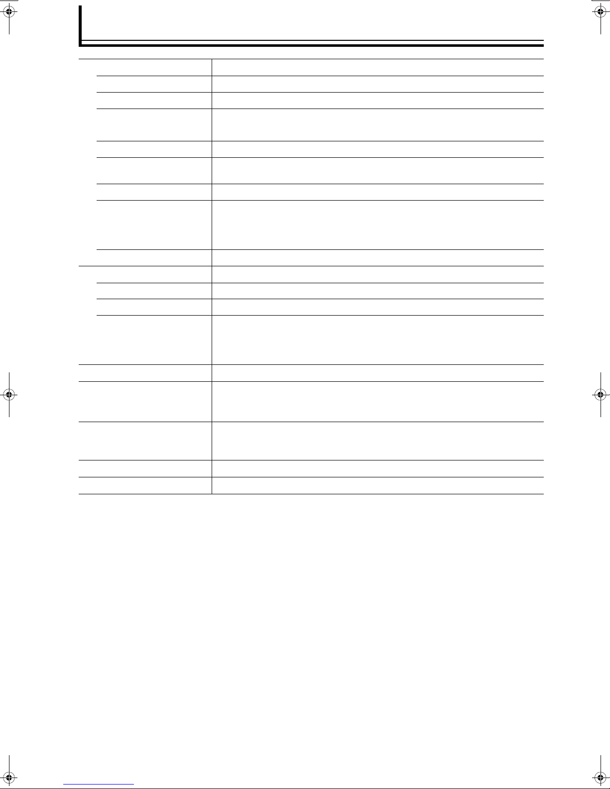
Specifications
o Input Terminal
VIDEO
S-VIDEO
COMPONENT/RGB
SYNC
COMPONENT/RGBHV
HDMI
ANALOG AUDIO
DIGITAL AUDIO
Optical Digital
Coaxial Digital
SERIAL PORT
o Output Terminal
COMPONENT/RGBHV
HDMI
DIGITAL AUDIO
Optical Digital
Coaxial Digital
o Power Requirements
o Operation Environment
o Dimensions
(Width x Height x Depth)
o Mass
o Accessories
2-line, RCA ⳯ 2 1.0 Vp-p
2-line, mini-DIN 4 pin ⳯ 2 Y: 1.0 Vp-p, C: 0.286 Vp-p
2-line, RCA ⳯ 6 Y/Gs (Sync on G): 1.0 Vp-p, Pb/Pr/R/G/B: 0.7 Vp-p
2-line, RCA ⳯ 2 1.0 Vp-p compatible with binary and ternary sync signals
1-line, BNC ⳯ 5 Y/Gs (Sync on G)/H/V: 1.0 Vp-p, Pb/Pr/R/G/B: 0.7 Vp-p
4-line
(Refer to the input terminal signal table for the video format. (A Page 11))
1-line 2-channel (L/R) RCA
2-line, S/PDIF Toslink
2-line, S/PDIF RCA
Not used.
1-line, BNC ⳯ 5 Y/Gs (Sync on G)/H/V: 1.0 Vp-p, Pb/Pr/R/G/B: 0.7 Vp-p
1-line
1-line, S/PDIF Toslink
1-line, S/PDIF RCA
DC6 V, 5 A and below (When using supplied AC adapter: AC100 V, 50 Hz/60 Hz)
Temperature : 41 J to 95 J (+5 I to +35 I)
Humidity : 20 % to 80 % (No condensation)
Storage Temperature : 14 J to 140 J (-10 I to +60 I)
Approx. 1 4/5" ⳯ approx. 17 " ⳯ approx. 10 2/5"
(Approx. 46 mm ⳯ Approx. 434 mm ⳯ Approx. 263 mm)
(Excluding protruding portion)
Approx. 6.6 lbs (Approx. 3.0 kg)
(Refer to Page 9.)
● Design and specifications (including menus) are subject to change without prior notice.
● Please note that some of the pictures and illustrations may have been abridged, enlarged or contextualized in order to aid
comprehension. Images may differ from the actual product.
26
Page 27

Memo
ENGLISH
27
Page 28

LD-HD1KU/LD-HD1KE
AV HUB PROCESSOR
© 2005 Victor Company of Japan, Limited
 Loading...