

Page 1
ENGLISH FRANÇAIS ESPAÑOL
D-ILA PROJECTOR
PROJECTEUR D-ILA
PROYECTOR D-ILA
DLA-RS2
INSTRUCTIONS
MANUEL D’INSTRUCTIONS
MANUAL DE INSTRUCCIONES
Getting Started Preparation Basic Operation Settings Troubleshooting Others
LCT2441-001B
Page 2
1
Getting Started
Safety Precautions
IMPORTANT INFORMATION
WARNING:
TO PREVENT FIRE OR SHOCK HAZARDS, DO NOT
EXPOSE THIS APPLIANCE TO RAIN OR MOISTURE.
WARNING:
THIS APPARATUS MUST BE EARTHED.
CAUTION:
To reduce the risk of electric shock, do not remove
cover. Refer servicing to qualified service personnel.
MACHINE NOISE INFORMATION (Germany only)
Changes Machine Noise Information Ordinance 3.
GSGV, January 18, 1991: The sound pressure level at
the operator position is equal or less than 70 dB (A)
according to ISO 7779.
About the installation place
Do not install the projector in a place that cannot support
its weight securely.
If the installation place is not sturdy enough, the projector
could fall or overturn, possibly causing personal injury.
- When the product is used on a cart,
care should be taken to avoid quick
stops, excessive force, and uneven
surfaces which may cause the product
and cart to overturn, damaging
equipment or causing possible injury to
the operator.
- Slots and openings in the cabinet are
provided for ventilation. These ensure
reliable operation of the product and protect it from
overheating. These openings must not be blocked or
covered. (The openings should never be blocked by
placing the product on bed, sofa, rug, or similar surface. It
should not be placed in a built-in installation such as a
bookcase or rack unless proper ventilation is provided and
the manufacturer’s instructions have been adhered to.)
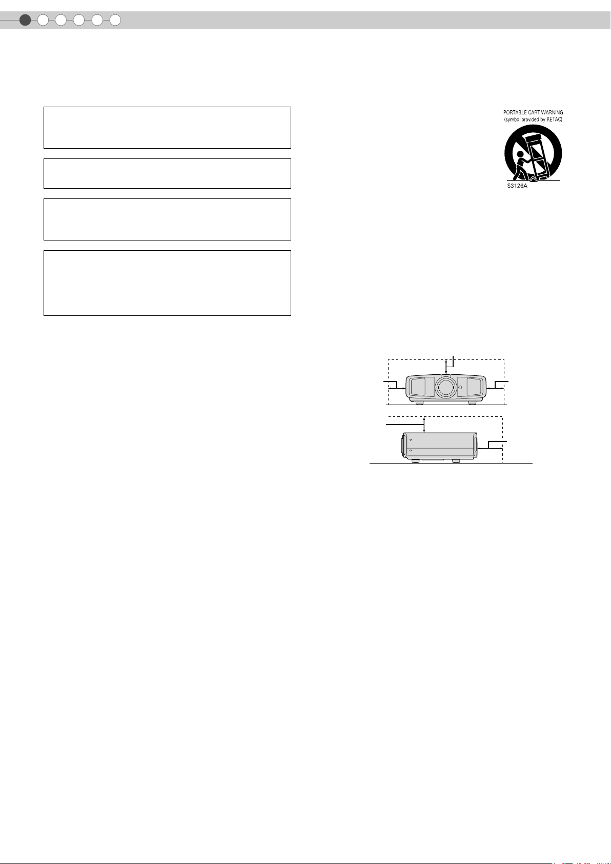
- To allow better heat dissipation, keep a clearance between
this unit and its surrounding as shown below. When this
unit is enclosed in a space of dimensions as shown below,
use an air-conditioner so that the internal and external
temperatures are the same.
150 mm and above
300 mm
and above
300 mm
and above
IMPORTANT SAFEGUARDS
Electrical energy can perform many useful functions. This
unit has been engineered and manufactured to assure
your personal safety. But IMPROPER USE CAN RESULT
IN POTENTIAL ELECTRICAL SHOCK OR FIRE
HAZARD. In order not to defeat the safeguards
incorporated into this product, observe the following basic
rules for its installation, use and service. Please read
these Important Safeguards carefully before use.
- All the safety and operating instructions should be read
before the product is operated.
- The safety and operating instructions should be retained
for future reference.
- All warnings on the product and in the operating
instructions should be adhered to.
- All operating instructions should be followed.
- Place the projector near a wall outlet where the plug can
be easily unplugged.
- Unplug this product from the wall outlet before cleaning.
Do not use liquid cleaners or aerosol cleaners. Use a
damp cloth for cleaning.
- Do not use attachments not recommended by the product
manufacturer as they may be hazardous.
- Do not use this product near water. Do not use
immediately after moving from a low temperature to high
temperature, as this causes condensation, which may
result in fire, electric shock, or other hazards.
- Do not place this product on an unstable cart, stand, or
table. The product may fall, causing serious injury to a
child or adult, and serious damage to the product. The
product should be mounted according to the
manufacturer’s instructions, and should use a mount
recommended by the manufacturer.
150 mm
and above
- This product should be operated only with the type of
power source indicated on the label. If you are not sure of
the type of power supply to your home, consult your
product dealer or local power company.
- This product is equipped with a three-wire plug. This plug
will fit only into a grounded power outlet. If you are unable
to insert the plug into the outlet, contact your electrician to
install the proper outlet. Do not defeat the safety purpose
of the grounded plug.
- Power-supply cords should be routed so that they are not
likely to be walked on or pinched by items placed upon or
against them. Pay particular attention to cords at doors,
plugs, receptacles, and the point where they exit from the
product.
- For added protection of this product during a lightning
storm, or when it is left unattended and unused for long
periods of time, unplug it from the wall outlet and
disconnect the cable system. This will prevent damage to
the product due to lightning and power line surges.
- Do not overload wall outlets, extension cords, or
convenience receptacles on other equipment as this can
result in a risk of fire or electric shock.
- Never push objects of any kind into this product through
openings as they may touch dangerous voltage points or
short out parts that could result in a fire or electric shock.
Never spill liquid of any kind on the product.
- Do not attempt to service this product yourself as opening
or removing covers may expose you to dangerous
voltages and other hazards. Refer all service to qualified
service personnel.
200 mm
and above
2
Page 3
-
Unplug this product from the wall outlet and refer service to
qualified service personnel under the following conditions:
a) When the power supply cord or plug is damaged.
b) If liquid has been spilled, or objects have fallen on the product.
c) If the product has been exposed to rain or water.
d) If the product does not operate normally by following the
operating instructions. Adjust only those controls that are
covered by the Operation Manual, as an improper adjustment
of controls may result in damage and will often require
extensive work by a qualified technician to restore the product
to normal operation.
e) If the product has been dropped or damaged in any way.
f) When the product exhibits a distinct change in performance -
this indicates a need for service.
- When replacement parts are required, be sure the service
technician has used replacement parts specified by the
manufacturer or with same characteristics as the original
part. Unauthorized substitutions may result in fire, electric
shock, or other hazards.
-
Upon completion of any service or repairs to this product,
ask the service technician to perform safety checks to
determine that the product is in proper operating condition.
- The product should be placed more than one foot away
from heat sources such as radiators, heat registers,
stoves, and other products (including amplifiers) that
produce heat.
- When connecting other products such as VCR’s, and DVD
players, you should turn off the power of this product for
protection against electric shock.
- Do not place combustibles behind the cooling fan. For
example, cloth, paper, matches, aerosol cans or gas
lighters that present special hazards when over heated.
- Do not look into the projection lens while the illumination
lamp is turned on. Exposure of your eyes to the strong
light can result in impaired eyesight.
- Do not look into the inside of this unit through vents
(ventilation holes), etc. Do not look at the illumination lamp
directly by opening the cabinet while the illumination lamp
is turned on. The illumination lamp also contains ultraviolet
rays and the light is so powerful that your eyesight can be
impaired.
- Do not drop, hit, or damage the light-source lamp (lamp
unit) in any way. It may cause the light-source lamp to
break and lead to injuries. Do not use a damaged light
source lamp. If the light-source lamp is broken, ask your
dealer to repair it. Fragments from a broken light-source
lamp may cause injuries.
- The light-source lamp used in this projector is a high
pressure mercury lamp. Be careful when disposing of the
lightsource lamp. If anything is unclear, please consult
your dealer.
- Do not ceiling-mount the projector to a place which tends
to vibrate; otherwise, the attaching fixture of the projector
could be broken by the vibration, possibly causing it to fall
or overturn, which could lead to personal injury.
- Use only the accessory cord designed for this product to
prevent shock.
ENGLISH
Getting Started Preparation Basic Operation Settings Troubleshooting Others
*DO NOT allow any unqualified person to install the
unit.
Be sure to ask your dealer to install the unit (e.g.
attaching it to the ceiling) since special technical
knowledge and skills are required for installation. If
installation is performed by an unqualified person, it
may cause personal injury or electrical shock.
3
Page 4
1
Getting Started
Safety Precautions (Continued)
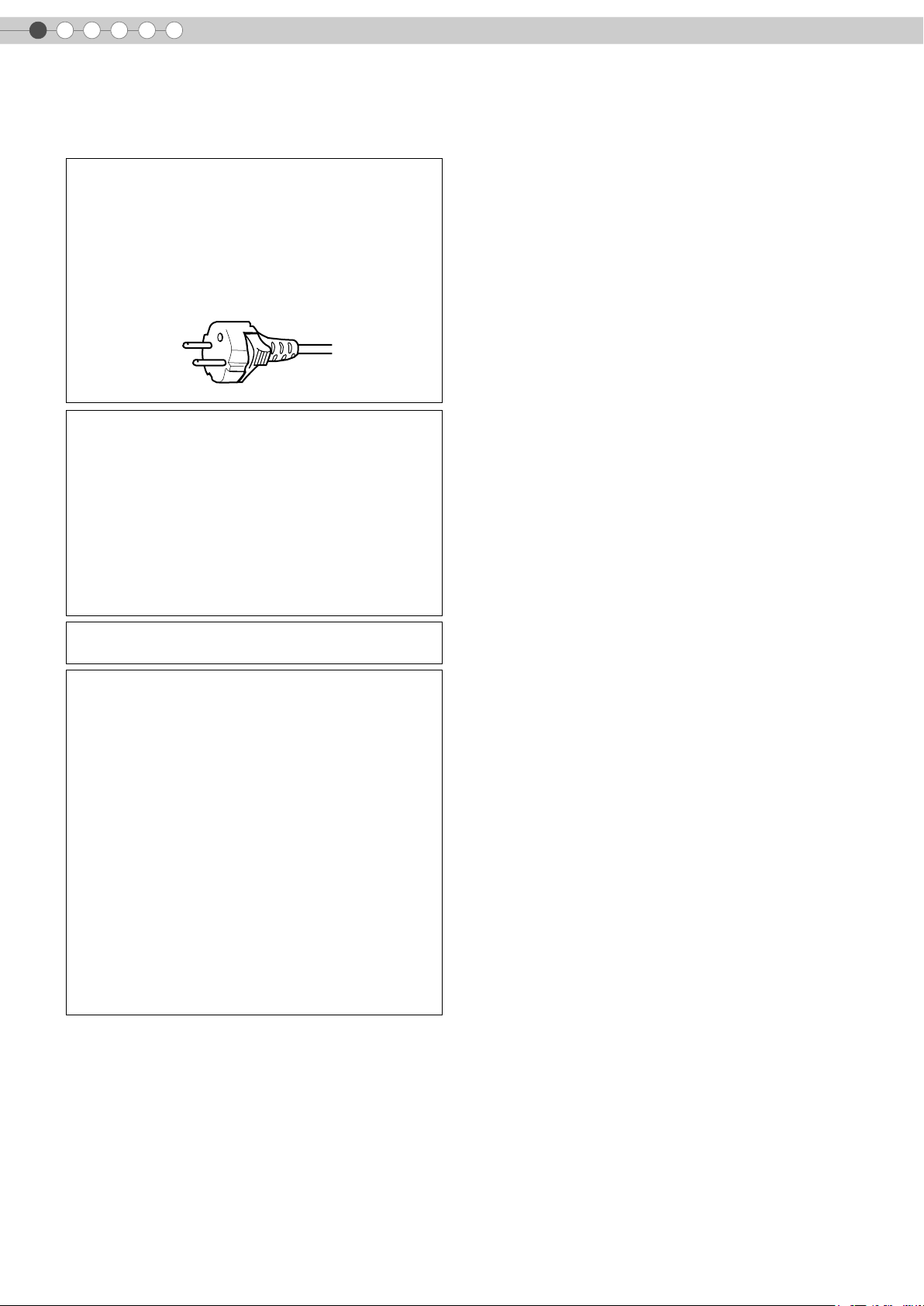
POWER CONNECTION
The power supply voltage rating of this product is
AC110 V – AC240 V. Use only the power cord
designated by our dealer to ensure Safety and EMC.
Ensure that the power cable used for the projector is the
correct type for the AC outlet in your country. Consult
your product dealer.
Power cord
WARNING:
Do not cut off the main plug from this equipment.
If the plug fitted is not suitable for the power points in
your home or the cable is too short to reach a power
point, then obtain an appropriate safety approved
extension lead or adapter or consult your dealer.
If nonetheless the mains plug is cut off, dispose of the
plug immediately, to avoid a possible shock hazard by
inadvertent connection to the main supply. If a new main
plug has to be fitted, then follow the instruction given
below.
WARNING:
THIS APPARATUS MUST BE EARTHED.
IMPORTANT:
The wires in the mains lead on this product are coloured
in accordance with the following cord:
Green-and-yellow : Earth
Blue : Neutral
Brown : Live
As these colours may not correspond with the coloured
making identifying the terminals in your plug, proceed
as follows:
The wire which is coloured green-and-yellow must be
connected to the terminal which is marked M with the
letter E or the safety earth or coloured green or greenand-yellow.
The wire which is coloured blue must be connected to
the terminal which is marked with the letter N or
coloured black.
The wire which is coloured brown must be connected to
the terminal which is marked with the letter L or
coloured red.
4
Page 5
ENGLISH
Dear Customer,
This apparatus is in conformance with the valid European directives and standards regarding electromagnetic
compatibility and electrical safety.
European representative of Victor Company of Japan, Limited is:
JVC Technical Services Europe GmbH
Postfach 10 05 04
61145 Friedberg
Germany
Getting Started Preparation Basic Operation Settings Troubleshooting Others
5
Page 6
Main Features
.
Supports Multiple Digital
Devices
...............................................
z Comes with a dual HDMI terminal that
allows digital transmission of high
definition signals. (pP14)
6
Page 7
.
Beautiful Images on Big Screen
.................................................................
z Enjoy smooth and high resolution video images with no
visible grid, brought about by full high definition resolution
of 1920 c 1080 pixels. (pP20)
Getting Started Preparation Basic Operation Settings Troubleshooting Others
Perfect for Any Location
........................................................
z Comes with an 80 % vertical and 34 % horizontal
lens shift function. (pP18)
7
Page 8

1
.
.
.
.
.
.
Getting Started
Contents
Getting Started
..................................................
Safety Precautions................................................2
Main Features .....................................................6
Contents..............................................................8
How to Read this Manual/
Accessories/Optional Accessories.......................9
About this Manual...........................................................9
Check the Accessories......................................................9
Optional Accessories.......................................................9
Controls and Features ........................................10
How to Use the Remote Control...........................13
Loading Batteries...........................................................13
Effective Range of Remote Control Unit............................13
Preparation
..................................................
Selecting Connecting Devices..............................14
Connecting........................................................15
Connecting via Video Cable and S-video Cable...............15
Connecting via Component Video Cable .........................15
Connecting via HDMI Cable...........................................16
Connecting via HDMI-DVI Conversion Cable ...................16
Connecting via SCART-RCA Cable..................................17
Connecting via RGB Video Cable ...................................17
Troubleshooting
..................................................
Troubleshooting.................................................36
What to Do When These Messages
Are Displayed .................................................38
About Warning Indicators..................................39
Actions to Be Taken for Warning Mode .......................... 39
Replacing the Lamp ...........................................40
Procedure for Lamp Replacement ................................... 40
Resetting Lamp Time...................................................... 42
Cleaning and Replacing the Filter........................43
Others
..................................................
RS-232C Interface .............................................44
RS-232C Specifications ................................................. 44
Command Format ......................................................... 44
RS-232C Communication Examples................................ 48
Copyright and Caution.......................................50
About Trademarks and Copyright .................................. 50
Caution........................................................................ 50
Mounting this Unit......................................................... 51
Specifications ....................................................52
Dimensions................................................................... 53
Installing the Projector and Screen.......................18
Screen Size and Projection Distance................................19
Basic Operation
..................................................
Projecting Image................................................20
Convenient Features during Projection.................22
Setting the Screen Size...................................................22
Masking the Surrounding Area of an Image ....................22
Settings
..................................................
Setting Menu .....................................................24
Procedures for Menu Operation .....................................24
Setting Menu.................................................................25
Customizing Projected Images ............................34
Changing the Default Image Profile Values......................34
Registering User-defined Image Profiles...........................35
Registering User-defined Image Profiles from the Menu ....35
8
Page 9
ENGLISH
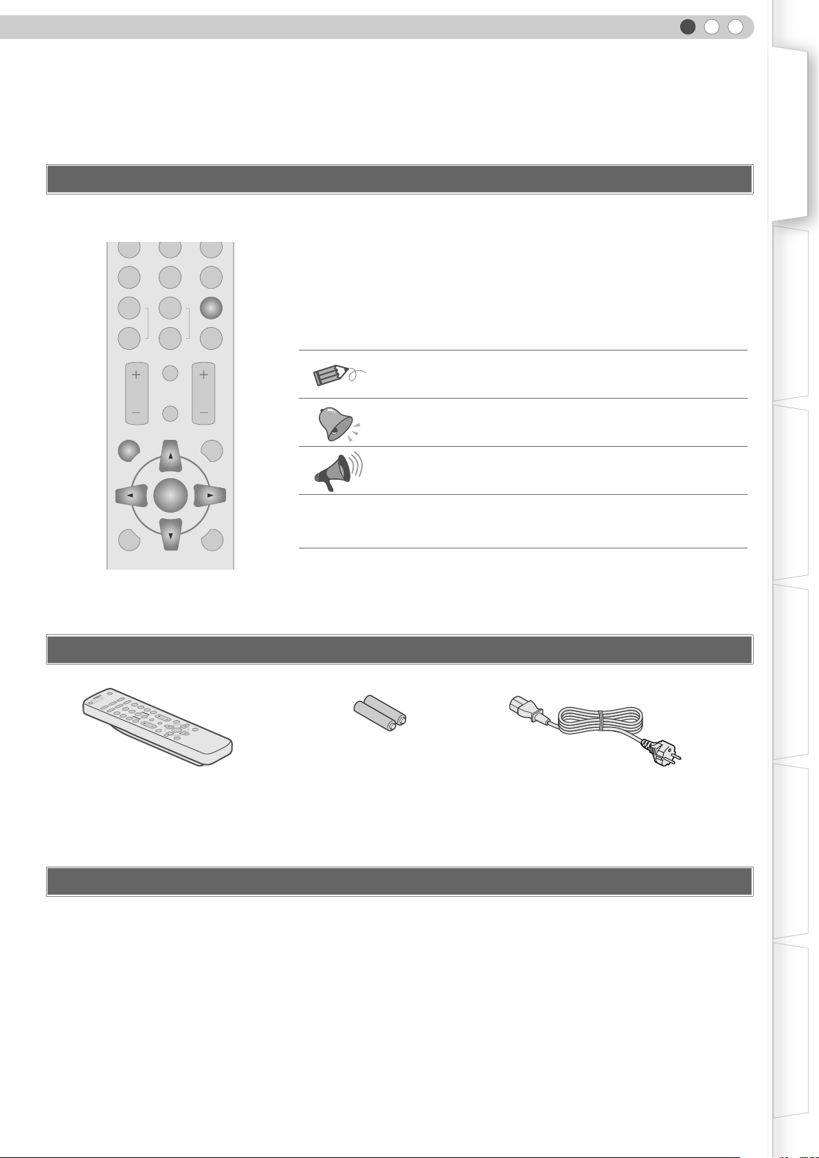
How to Read this Manual/ Accessories/Optional Accessories
About this Manual
Getting Started Preparation Basic Operation Settings Troubleshooting Others
N
C
USER
1
COLOR
+
COLOR
-
CONTRAST
USER
SHARP
SHARP
D
USER
2
3
GAMMA
+
COLOR
-
TEMP
BRIGHT
INFO
HIDE
MENU
EXIT
ENTER
LIGHTTEST
Buttons to be used are coloured in a
darker shade.
This manual mainly describes the operating method using the remote
control.
Buttons on the remote control are described as [Button Name].
z
z Selection items on the menu are described as “Selection Item”.
Conventions in this manual
Describes the limitations of the functions or usage.
Indicates good-to-know information.
Describes operational precautions.
pP9
Indicates related pages.
Check the Accessories
N
O
.
.
..
.
.
.
.
E
AT
R
PE
O
P
.
M
.
..
O
.
.
C
.
.
T
F
C
F
O
C
E
P
MI
2
S
I
A
A
M
N
D
H
DY
D
O
E
D
I
AL
R
V
1
-
E
R
I
S
S
U
M
3
U
D
AT
H
N
A
N
M
O
M
E
A
D
I
G
V
SER
EMA
2
U
O
N
L
I
C
E
CO
P
T
C
R
A
H
+
S
SER
P
B
1
U
AR
-
SH
R
O
L
+
CO
O
F
N
R
I
T
O
S
L
A
-
CO
R
T
N
CO
Remote Control
R
P
M
T
H
G
I
R
T
I
EX
E
D
I
H
T
R
H
E
IG
U
L
T
EN
M
EN
T
ES
T
AAA size Batteries
(for operation confirmation)
z Instruction manual and other printed material are also included.
Optional Accessories
Please check with your authorized dealer for details.
Replacement Lamp: BHL5009-S (Lamp Unit)
z
z Replacement Filter: LC32058-002A (Inner Filter)
Power Cord
(2 m)
9
Page 10
1
Getting Started
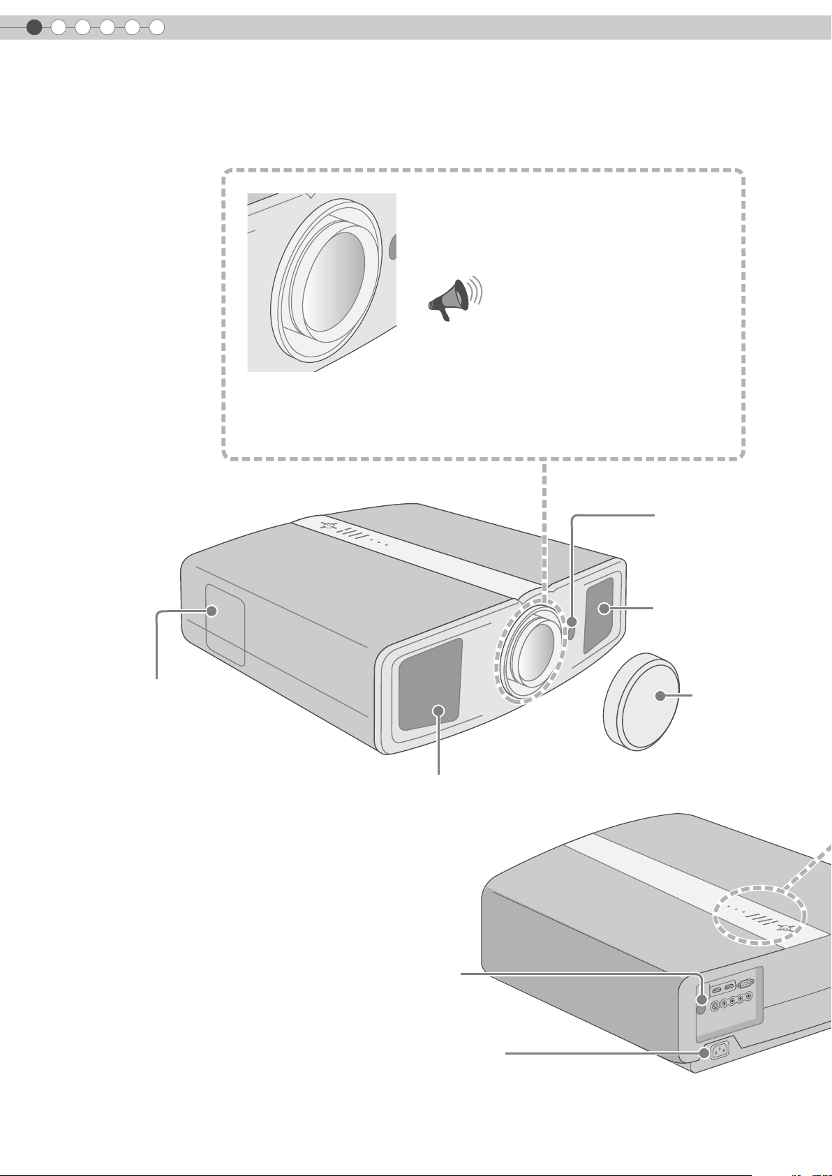
Controls and Features
z This unit comes with buffer material that cushions the lens. Remove the buffer
material before use.
z Do not throw away the buffer material, retain for future use. (pP50)
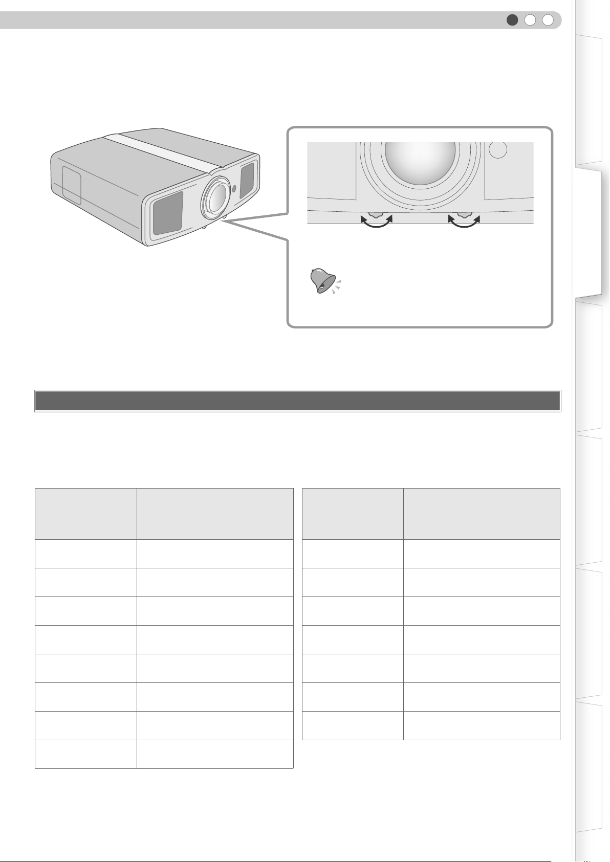
To adjust the focus.
To adjust the size of the image.
z Operate using the remote control. (pP20)
CAUTION
z Do not turn the lens with your hands.
Front Side/Left Side
Lamp Cover (pP40)
Remote Sensor
(pP13)
Air Inlets
Lens Cap
Exhaust Vent
Rear Side/Top Surface
10
Remote Sensor (pP13)
To connect the power cord (pP20)
Page 11
ENGLISH
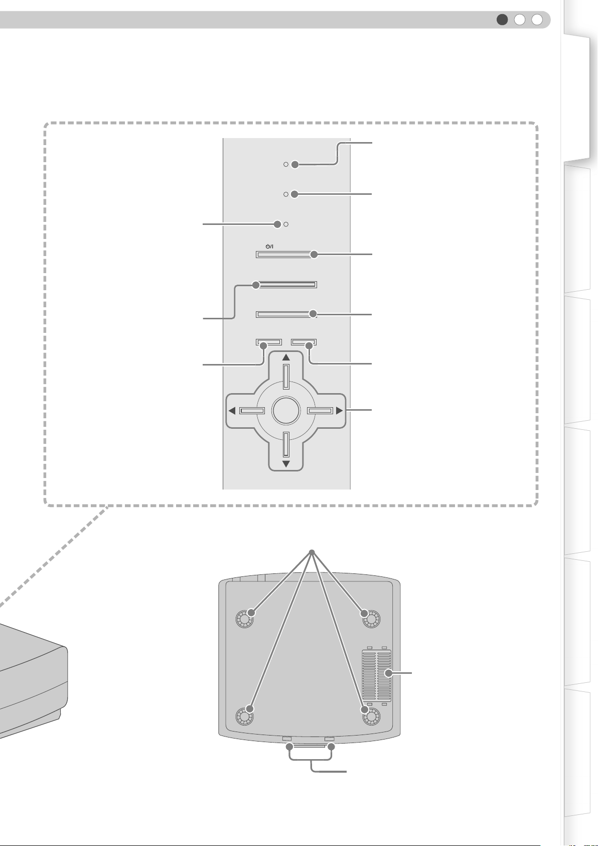
Getting Started Preparation Basic Operation Settings Troubleshooting Others
Light on (Red):
Standby mode
Light on (Green):
During projection
Blinking (Green):
Image is temporarily hidden
(pP21)
Blinking (Red):
Cool Down mode (pP21)
To switch input
To display the menu
(pP20)
(pP24)
STANDBY/ON
MENU
WARNING
LAMP
STANDBY/ON
INPUT
HIDE
ENTER
Light on (Red):
Warning mode (pP39)
Light on/Blinking (Orange):
Lamp warning (pP39)
To turn on/off the power
To hide the image temporarily (pP21)
EXIT
To return to the previous menu
To select or confirm
Bottom Surface
Feet: The height (0 to 5 mm) can be adjusted by turning the foot.
Air Inlets/Filter (pP43)
To adjust the position of the image (pP19)
11
Page 12
1
Getting Started
Controls and Features (Continued)
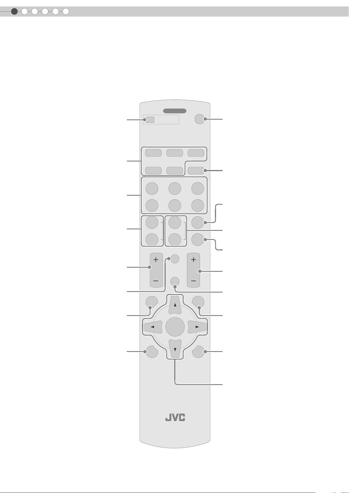
Remote Control
To turn off the power
Select input mode (pP20)
To switch image profile
(pP34)
To adjust colour density
(pP34)
To adjust contrast
(pP34)
To display information
........ ........
OFF
COLOR
COLOR
CONTRAST
MENU
OPERATE
HDMI 1 COMP.
C
USER
1
+
-
HDMI 2
S-VIDEOVIDEO ASPECT
NATURALCINEMA DYNAMIC
N
USER
2
SHARP
+
SHARP
-
BRIGHT
INFO
HIDE
ON
D
USER
3
GAMMA
COLOR
TEMP
EXIT
To turn on the power
To set the screen size
(pP22)
To set gamma
(pP34)
To adjust the outline of the image
(pP34)
To set colour temperature
(pP34)
To adjust brightness
(pP34)
To hide the image temporarily
(pP21)
12
To display the menu
(pP24)
To display test patterns
For adjusting the image size
(zoom) and the focus. (pP20)
ENTER
PROJECTOR
To return to the previous menu
LIGHTTEST
To illuminate buttons on the remote control
To select or confirm
Page 13
ENGLISH
How to Use the Remote Control
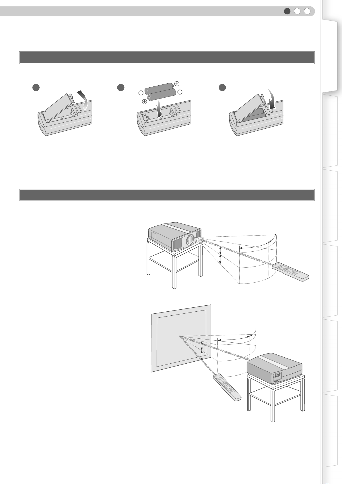
Loading Batteries
12 3
z If the remote control has to be brought closer to the projector to operate, it means that the batteries are wearing out. When this
happens, replace the batteries. Insert the batteries according to the +- marks.
z Be sure to insert the - end first.
z If an error occurs when using the remote control, remove the batteries and wait for 5 minutes. Load the batteries again and
operate the remote control.
Getting Started Preparation Basic Operation Settings Troubleshooting Others
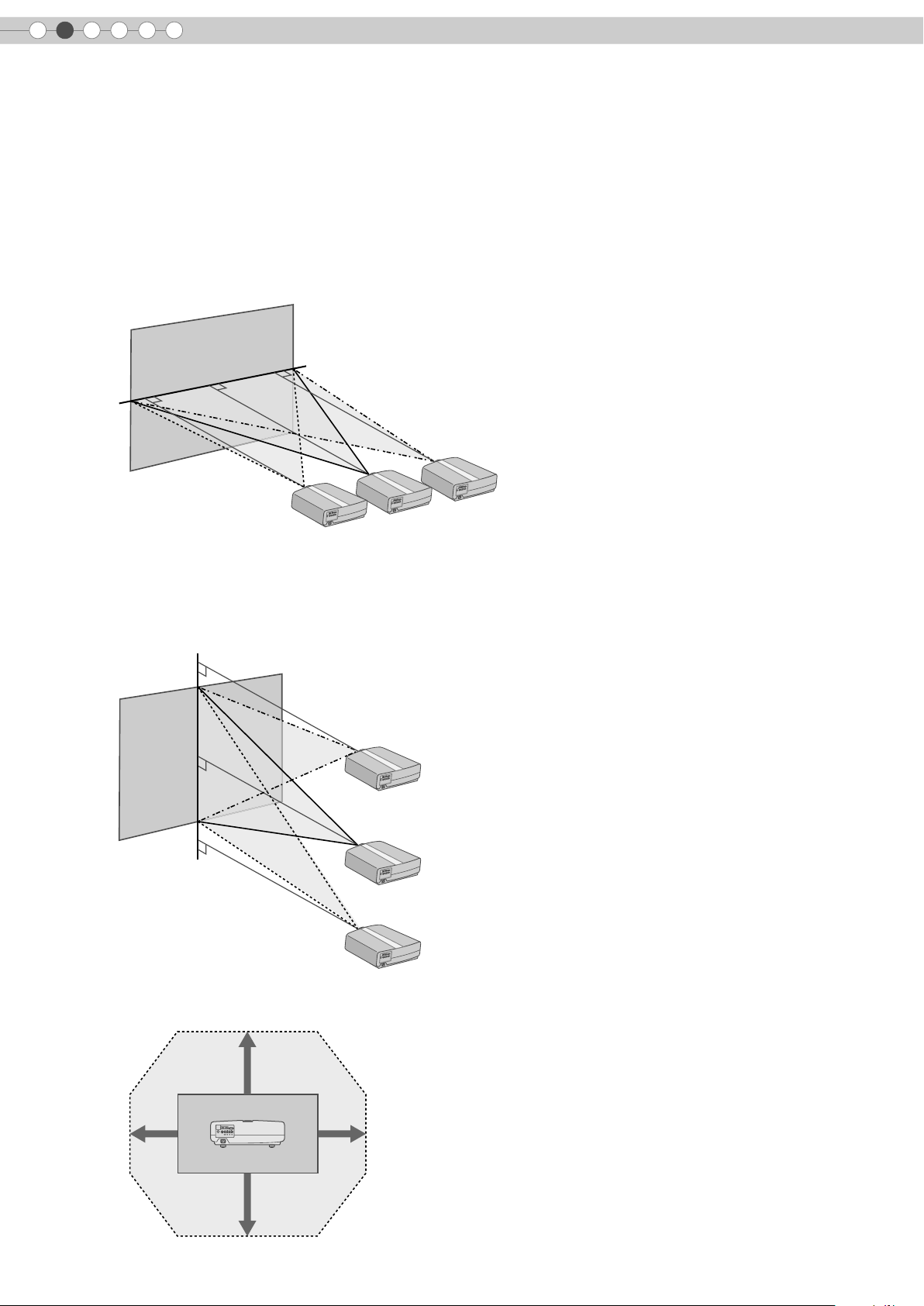
Effective Range of Remote Control Unit
When directing the remote control
toward this unit
When aiming the remote control towards the
z
remote sensor on this unit, ensure that the
distance to the sensor in front or at the rear of
this unit is within 7 m.
z If the remote control fails to work properly,
move closer to this unit.
When reflecting off a screen
Ensure that total of distance A between this
z
unit and screen and distance B between
remote control and screen is within 7 m.
z As the efficiency of signals reflected from the
remote control unit differ with the type of
screen used, operable distance may
decrease.
Screen
This unit
30°
30°
30°
30°
30°
30°
30°
20°
20°
20°
N
O
.
.....
..
E
T
A
20°
20°
20°
R
E
P
O
.
MP
..
O
...
C
..
T
F
C
F
C
E
I
O
P
M
2
S
I
A
A
M
N
D
Y
H
D
D
O
E
L
D
I
A
R
V
1
-
E
R
S
S
U
MI
3
U
T
D
A
H
N
A
N
M
O
M
E
A
D
I
G
A
R
V
E
M
S
R
E
2
U
O
P
N
L
I
M
O
C
E
C
P
T
C
R
T
A
H
H
+
S
G
I
R
E
R
S
P
B
1
U
R
A
H
S
R
O
L
O
+
C
O
F
N
R
I
T
O
S
L
A
O
T
C
R
I
X
T
E
E
ON
D
I
C
H
T
R
H
G
E
I
U
L
N
NT
E
M
E
T
S
E
T
Remote Control
30°
30°
30°
30°
This unit
20°
20°
A
A
20°
20°
B
B
ON
...
.
.
..
E
T
RA
E
P
O
..
..
..
..
.
F
F
O
P
M
O
C
2
I
M
D
H
1
I
M
D
T
H
C
ASPE
C
I
EO
M
D
A
I
V
N
Y
S-
D
L
A
EO
R
D
I
U
V
T
A
D
N
A
M
INE
C
N
R
E
S
C
U
3
R
E
S
U
2
R
E
S
A
U
M
M
1
A
G
P
R
A
H
S
+
R
O
L
R
O
O
L
C
O
C
P
+
M
E
T
P
R
A
H
S
T
-
H
G
I
R
R
B
O
L
O
C
-
T
S
A
R
T
N
O
F
O
N
I
C
E
D
I
H
T
I
X
E
U
N
E
M
R
E
NT
E
T
H
G
I
L
T
S
E
T
Remote Control
13
Page 14
2
C
O
M
PONEN
T
Preparation
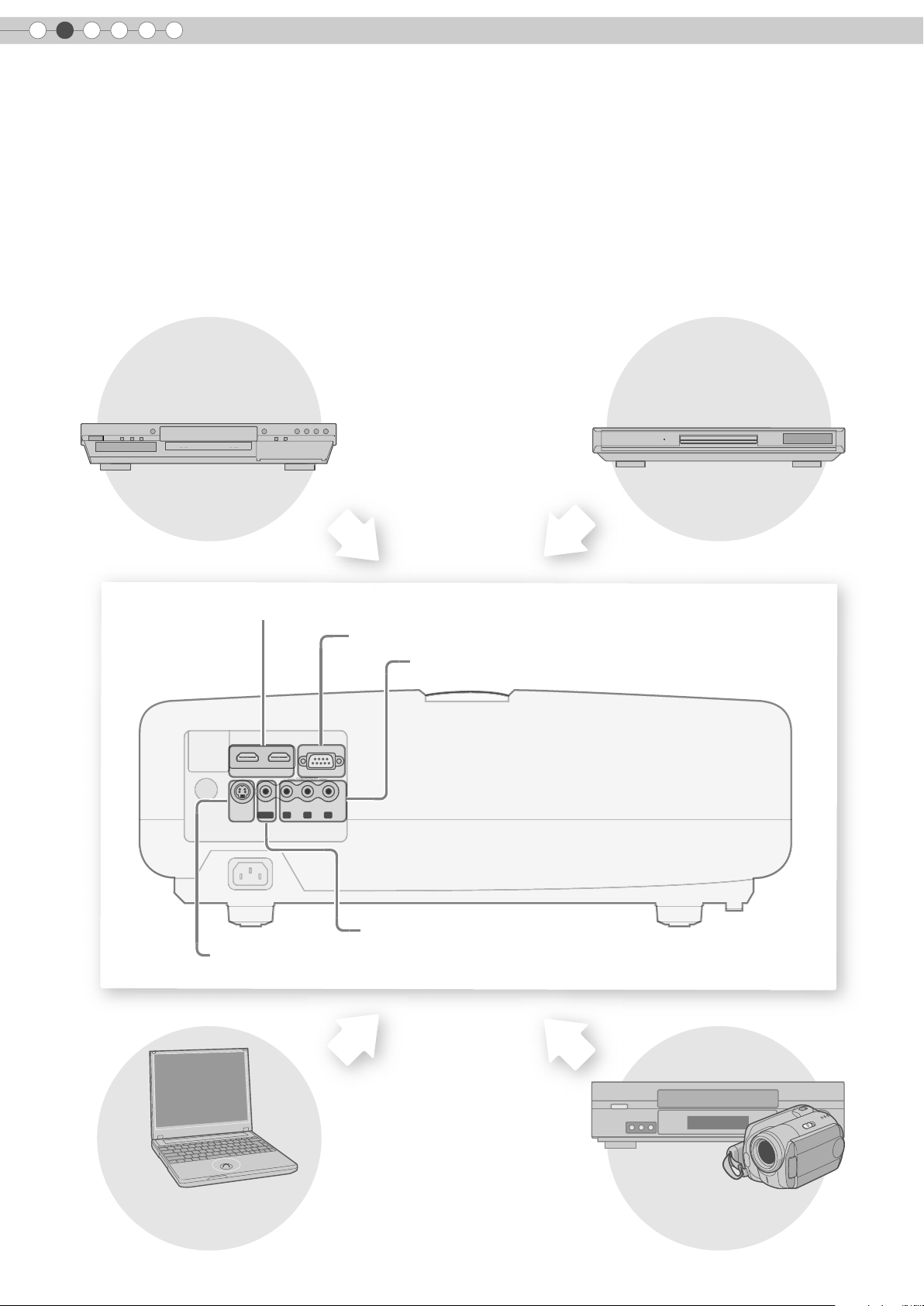
Selecting Connecting Devices
z Do not turn on the power until connection is complete.
z The connection procedures differ according to the device used. For details, refer to the instruction manual of the device to be
connected.
z For audio output, connect the device to an amplifier.
z The images may not be displayed depending on the devices and cables to be connected.
Use an HDMI compliant cable (sold separately) with the HDMI logo.
z It may not be possible to connect to this unit depending on the dimension of the connector cover of the cables to be
connected.
DVD Recorder DVD Player
To connect via HDMI terminal (pP16)
To connect RS-232C terminal
To connect via component video terminals (pP15)
HDMI 2 HDMI 1 RS-232C
S-VIDEO
VIDEO
Y CB/PB CR/PR
GBR
SYNC
COMPONENT
To connect via video terminal (pP15)
To connect via S-video terminal (pP15)
Notebook PC
VCR and camcorder
14
Page 15
Connecting
S-3
C
M
PONEN
T
C
B
/
P
BCR
/
P
R
G
B
R
S
VID
E
O
S3C
VID
E
O
S
Y
N
C
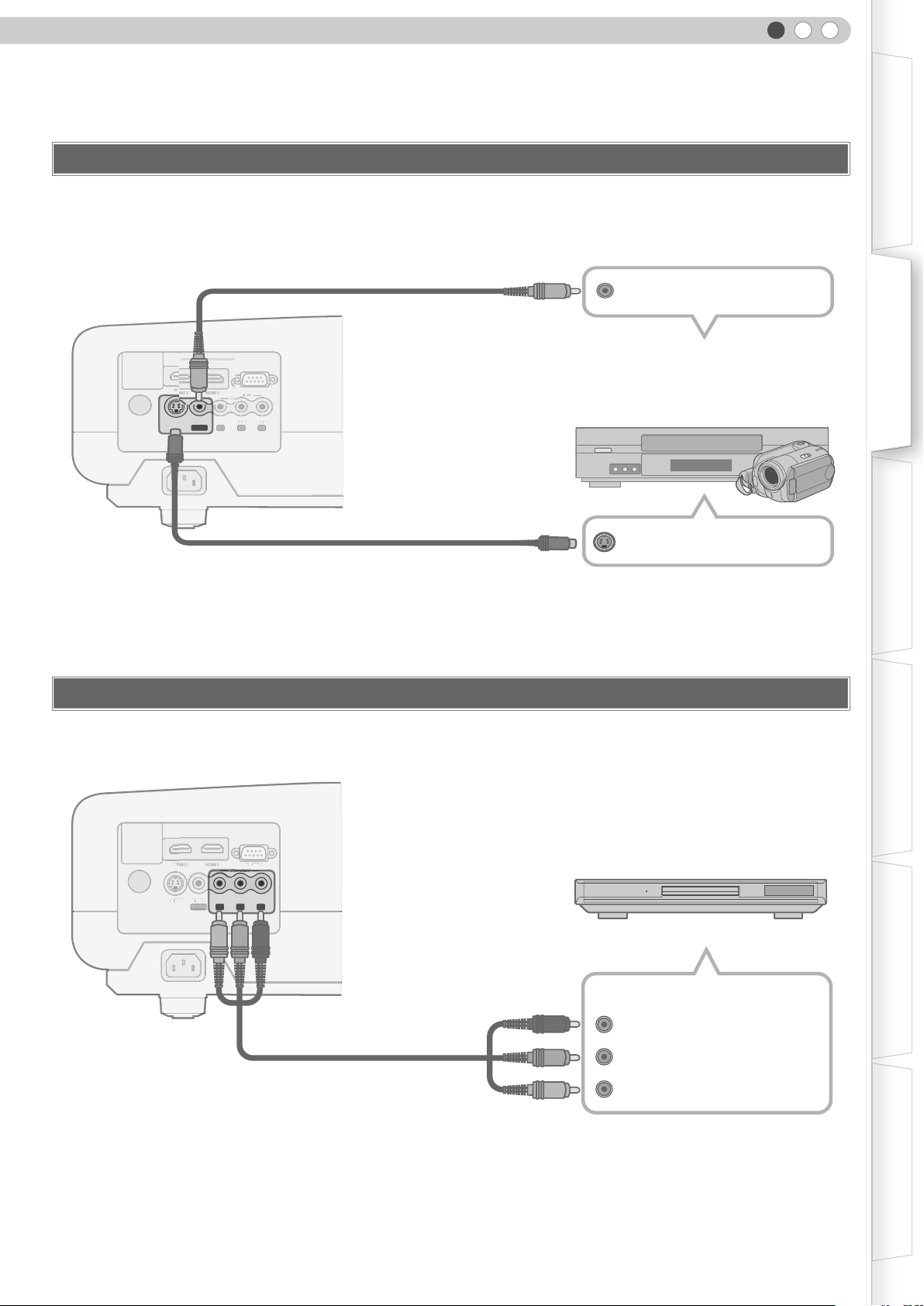
Connecting via Video Cable and S-video Cable
This unit
ENGLISH
Getting Started Preparation Basic Operation Settings Troubleshooting Others
To video input terminal
HD RS-232C
S-VIDEO
VIDEO
SYNC
OMPONENT
Y CB/PBCR/P
Y
GBR
Video cable (sold separately)
R
S-video cable (sold separately)
To S-video input terminal
Connecting via Component Video Cable
Video output
VCR and camcorder
S-video output
This unit
HD RS-232C
S-VIDEO
VIDEO
Y CB/PB CR/PR
SYNC
GBR
OMPONENT
Component video cable
(sold separately)
To component video input terminals
z Set “COMP” in the setting menu to “Y Pb/Cb Pr/Cr”. (pP28 - Q)
DVD player
Component video output terminals
(Red)
C
R/PR
CB/PB(Blue)
Y (Green)
15
Page 16
2
S
O
RS-232
C
C
OPO
O
S
C
C/C
/
G
S
O
RS232
C
COO
O
S
C
C/C
/
G
Preparation
Connecting (Continued)
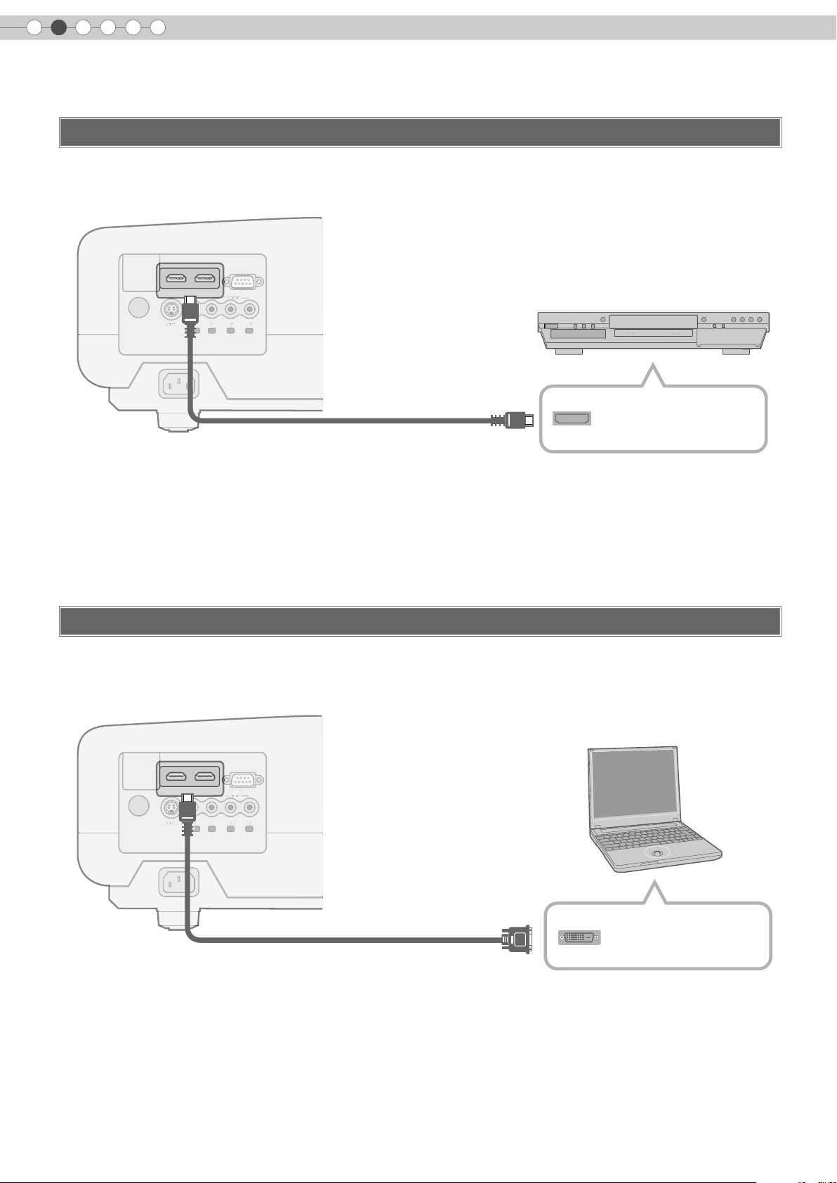
Connecting via HDMI Cable
This unit
HDMI 2 HDMI 1 RS-232C
S-VIDEO
VIDEO
Y CB/PB CR/PR
Y
SYNC
GBR
COMPONENT
E
R
HDMI cable (sold separately)
To HDMI 1 or HDMI 2
input terminal
Connecting via HDMI-DVI Conversion Cable
DVD recorder
HDMI output terminal
This unit
MDMI 2 MDMI1 RS-232C
S-VIDEO
To HDMI 1 or HDMI 2
input terminal
COMPONENT
VIDEO
Y CB/PB CR/PR
SYNC
GBR
HDMI-DVI conversion cable (sold separately)
Notebook PC
DVI output terminal
16
Page 17
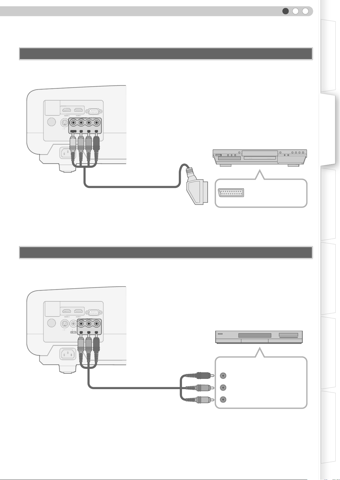
Connecting via SCART-RCA Cable
S
VID
E
O
S3C
S
VID
E
O
S3C
VID
E
O
S
Y
N
C
This unit
ENGLISH
Getting Started Preparation Basic Operation Settings Troubleshooting Others
HD RS-232C
S-VIDEO
VIDEO
Y CB/PB CR/PR
GBR
SYNC
OMPONENT
SCART-RCA cable
(sold separately)
To RGB video and sync signal input terminals
z Set “COMP” in the setting menu to “SCART”. (pP28 - Q)
Connecting via RGB Video Cable
This unit
DVD player for European market
SCART terminal
HD RS-232C
S-VIDEO
-
VIDEO
Y CB/PB CR/PR
SYNC
GBR
OMPONENT
Device equipped with RGB output
RGB video output terminals
RGB video cable
R (Red)
(sold separately)
B (Blue)
To RGB video input terminals
G (Green) (Includes sync signal)
z Set “COMP” in the setting menu to “RGB”. (pP28 - Q)
z For information on compatible input signals, see “Specifications”. (pP52)
17
Page 18
2
Preparation
Installing the Projector and Screen
Install this unit and the screen. Place this unit and the screen perpendicular to each other.
Failing to do so may give rise to trapezoidal distortion of the projected image.
A Install the projector and screen
Left/Right position
*0 % up/down position (centre)
Approximately 34 % (maximum) of the projected image
(Turn the dial to the right for maximum)
Approximately 34 % (maximum) of the projected image
(Turn the dial to the left for maximum)
Up/Down position
*0 % left/right position (centre)
Approximately 80 % (maximum) of the projected image
(Turn the dial to the left for maximum)
Approximately 80 % (maximum) of the projected image
(Turn the dial to the right for maximum)
18
Shifting range of projected image
80%
34% 34%
80%
MDMI2 MDMI1 RS-232C
COMPONENT
S-VIDEO
VIDEO
Y CB/PBCR/P
R
SYNC
GBR
Page 19
ENGLISH
B Adjust such that the projected image is in the centre of the screen
Getting Started Preparation Basic Operation Settings Troubleshooting Others
Moves the image to the
left or right
Moves the image up or
down
TIPS
z Adjustment can be done easily by moving the image
upwards towards the centre.
z It may be necessary to set “Pixel Adjust” in the setting menu after adjusting the image position. (pP27 - J)
Screen Size and Projection Distance
Determine the distance from the lens to the screen to achieve your desired screen size.
This unit uses a 2.0x power zoom lens for projection.
Relationship Between Projection Screen Size and Projection Distance
Projection Screen
Size
(Diagonal Length)
Aspect Ratio 16:9
60"
(Approx. 1.52 m)
Approximate Projection Distance
W (Wide) to T (Tele)
Approx.
1.78 m
to
Approx.
3.63 m
Projection Screen
Size
(Diagonal Length)
Aspect Ratio 16:9
140"
(Approx. 3.56 m)
Approximate Projection Distance
W (Wide) to T (Tele)
Approx.
4.24 m
to
Approx.
8.54 m
70"
(Approx. 1.78 m)
80"
(Approx. 2.03 m)
90"
(Approx. 2.29 m)
100"
(Approx. 2.54 m)
110"
(Approx. 2.79 m)
120"
(Approx.3.05 m)
130"
(Approx. 3.30 m)
z
The projection distances in the table are provided only as a guide. Use them as a reference during installation.
Approx.
2.09 m
Approx.
2.40 m
Approx.
2.71 m
Approx.
3.01 m
Approx.
3.32 m
Approx.
3.63 m
Approx.
3.93 m
to
to
to
to
to
to
to
Approx.
4.24 m
Approx.
4.86 m
Approx.
5.47 m
Approx.
6.08 m
Approx.
6.70 m
Approx.
7.31 m
Approx.
7.93 m
150"
(Approx. 3.81 m)
160"
(Approx. 4.06 m)
170"
(Approx. 4.32 m)
180"
(Approx. 4.57 m)
190"
(Approx. 4.83 m)
200"
(Approx. 5.08 m)
Approx.
4.55 m
Approx.
4.86 m
Approx.
5.16 m
Approx.
5.47 m
Approx.
5.78 m
Approx.
6.08 m
z To adjust the installation, use a projected image of aspect ratio 16:9.
to
to
to
to
to
to
Approx.
9.16 m
Approx.
9.77 m
Approx.
10.38 m
Approx.
11.00 m
Approx.
11.61 m
Approx.
12.23 m
19
Page 20
3
.
Basic Operation
Projecting Image
This section describes the basic operations to project input images on the screen.
Preparation
......................................................................
........ ........
OFF
OPERATE
HDMI 1 COMP.
HDMI 2
S-VIDEOVIDEO ASPECT
NATURALCINEMA DYNAMIC
N
C
USER
USER
2
1
USER
ON
D
3
z Remove the lens cap.
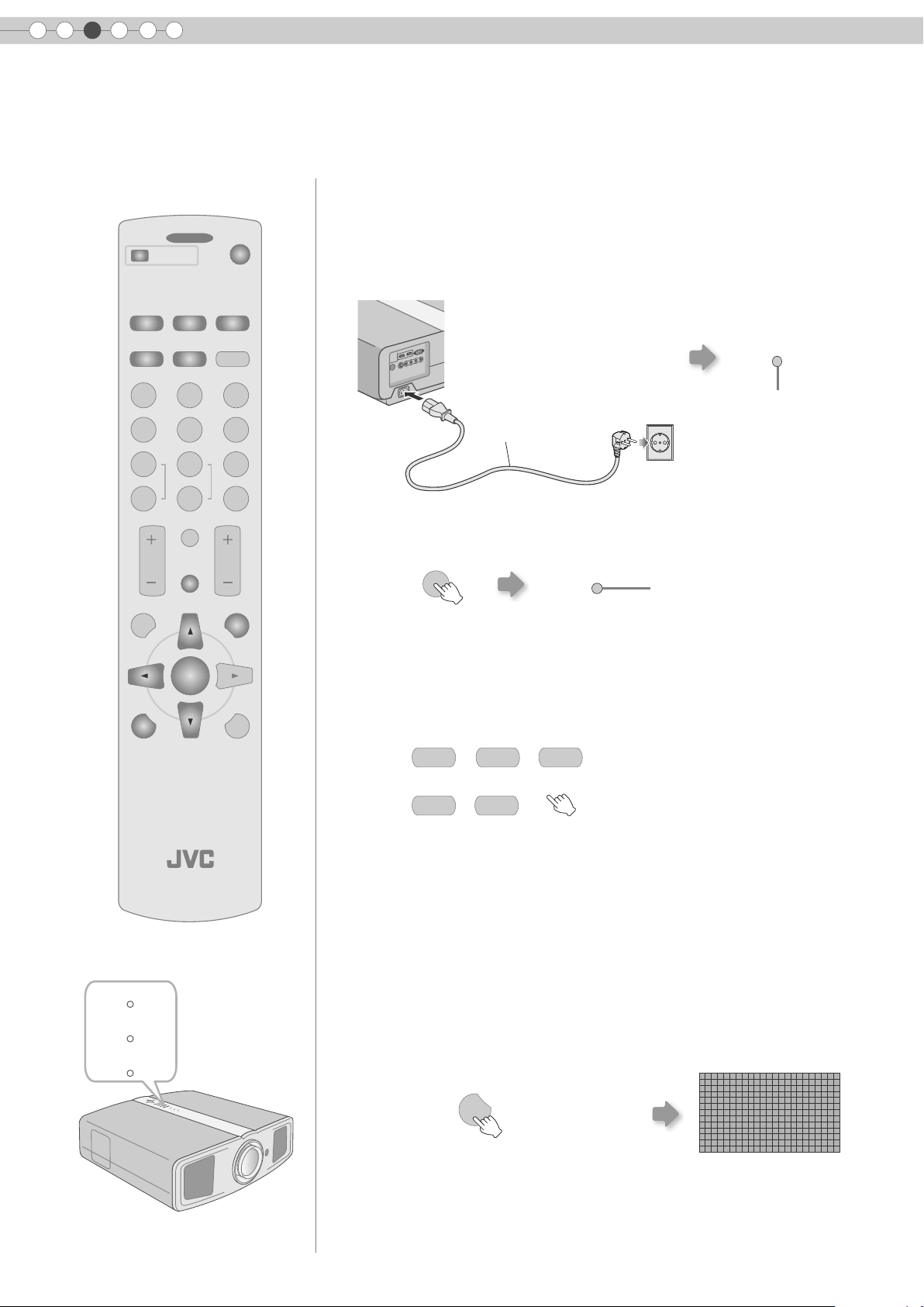
A Insert the power plug to the power outlet
A Connect to this unit
B Connect to the power outlet
A
Power Cord
(Supplied)
B
STANDBY/ON
Light on (Red)
COLOR
+
COLOR
-
CONTRAST
MENU
PROJECTOR
SHARP
+
SHARP
-
INFO
HIDE
ENTER
GAMMA
COLOR
BRIGHT
TEMP
EXIT
LIGHTTEST
B Turn on the power
ON
STANDBY/ON
z You can also press the [STANDBY/ON] button on the unit to turn on the
power. (pP11)
C Project the image
a Select input mode
COMP.HDMI 2HDMI 1
VIDEO S-VIDEO
z You can also select the input mode by pressing the [INPUT] button on
the unit. (pP11)
b Play back the selected device
Light on (Green)
20
WARNING
LAMP
STANDBY/ON
D Adjust the position of the projection screen
z See “Installing the Projector and Screen” for procedures on adjusting the
position. (pP18)
E Adjust the image size (zoom) and the focus
a Display the test pattern (crosshatch)
TEST
Press repeatedly
Page 21
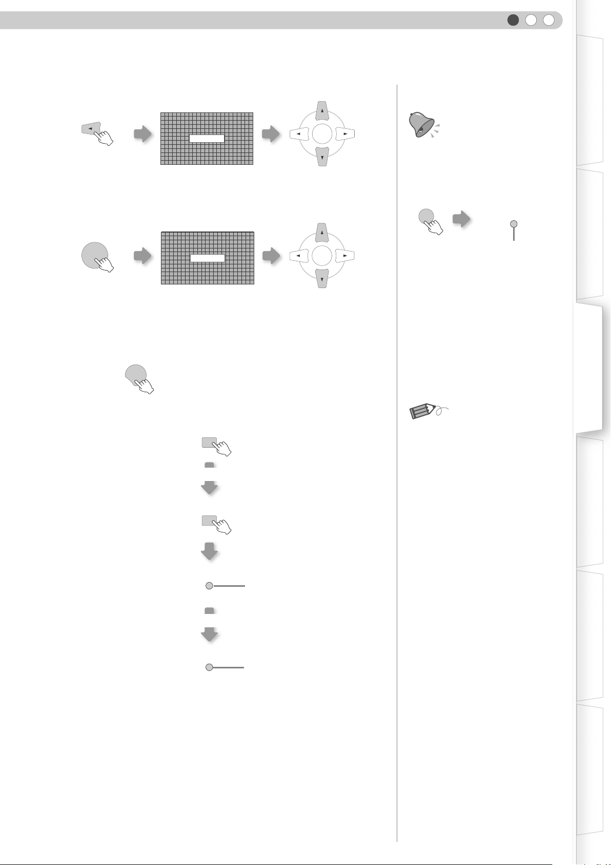
b Adjust the focus
ENGLISH
Getting Started Preparation Basic Operation Settings Troubleshooting Others
Press for 1 second
or more
c Adjust the image size (zoom)
ENTER
z Switches between “Focus” and “Zoom” whenever the [ENTER] button is
pressed.
d To end
EXIT
F Turn off the power
While a confirmation screen is displayed
STANDBY/ON
Cool Down mode
STANDBY/ON
z The power cannot be turned off within approximately 90 seconds after it
has been turned on. Start operation only after 90 seconds time.
z You can also press the [STANDBY/ON] button on the unit to turn off the
power. (pP11)
z Put back the lens cap after use to prevent the lens from dirt.
z Pull out the power plug when the unit will not be used for a prolonged time.
Focus
Zoom
OFF
OFF
ENTER
Adjust accordingly by
pressing the up down buttons
ENTER
Adjust accordingly by
pressing the up down buttons
Blinking (Red)
Light on (Red)
TIPS
You can hide the image
temporarily
...............................
You can hide the image temporarily.
HIDE
STANDBY/ON
Green light blinks when
the image is hidden
z Press the [HIDE] button again to
display image.
z The power cannot be turned off
when the image is temporarily
hidden.
MEMO
About Cool Down mode
...............................
z
The Cool Down mode is a function
to cool down the lamp for
approximately 60 seconds after
projection is complete.
This function prevents the internal
parts of the unit from deformation
or damage due to overheating of
the lamp. It also prevents lamp
blowout and premature shortening
of lamp life.
z During Cool Down mode, the
[STANDBY/ON] indicator blinks in
red.
z After the Cool Down mode is
complete, the unit automatically
returns to standby mode.
z Do not pull out the power plug
during Cool Down mode. This may
shorten the lamp life and cause a
malfunction.
21
Page 22
3
Basic Operation
Convenient Features during Projection
You can change the screen size of the projected image or hide the surrounding area of an image for which
quality at the outer area has deteriorated.
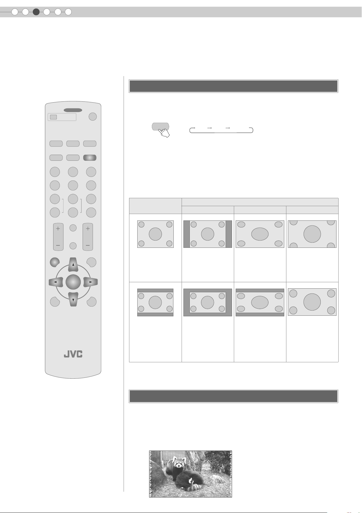
Setting the Screen Size
The projected image can be set to a most appropriate screen size (aspect
........ ........
OFF
OPERATE
ON
ratio).
HDMI 1 COMP.
HDMI 2
S-VIDEOVIDEO ASPECT
NATURALCINEMA DYNAMIC
N
C
USER
COLOR
COLOR
CONTRAST
MENU
USER
2
1
SHARP
+
+
SHARP
-
-
BRIGHT
INFO
HIDE
ENTER
D
USER
3
GAMMA
COLOR
TEMP
EXIT
LIGHTTEST
ASPECT
The screen size can also be set from “Aspect” of the setting menu. (pP29 - S)
z
4:3 16:9 ZOOM
z When high definition images are input, the “V-Stretch” setting will be available
instead. (pP29 - T)
z When PC signals are input, the “Resize” setting will be available instead.
(pP29 - U)
Input Image and Projected Image by Different Screen Size Settings
Input Image
SDTV(4:3)
4:3 16:9 Zoom
Aspect Ratio: Same
Most appropriate
screen size
Screen Size
Aspect Ratio:
Landscape
Image is stretched
horizontally
Aspect Ratio: Same
Top and bottom of the
image are missing
PROJECTOR
SDTV(4:3)
Image recorded in
landscape (black
bands on top and
Aspect Ratio: Same
Small image is
projected
Aspect Ratio:
Landscape
Image is stretched
horizontally
Aspect Ratio: Same
Most appropriate
screen size
bottom) of DVD
software
Depending on the input image, selecting “4:3” may result in a vertically stretched
z
image while selecting “16:9” provides you with the most appropriate screen size.
Masking the Surrounding Area of an Image
Images for which quality at the outer area has deteriorated can be projected
by masking (hiding) the surrounding area of the projected image.
A Project the image
iImage for which quality at the outer
area has deteriorated.
22
Page 23
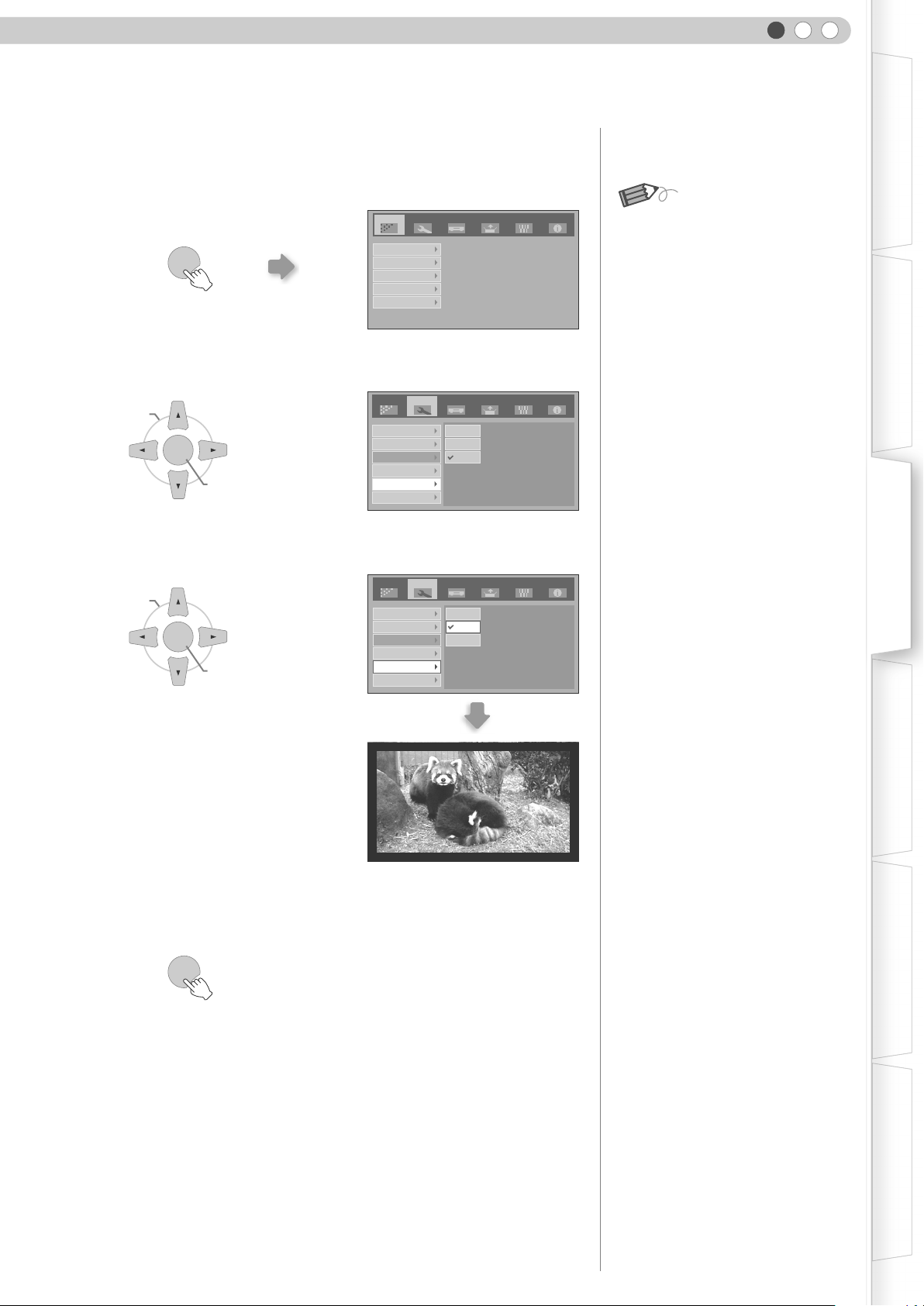
B Mask the image
ENGLISH
Getting Started Preparation Basic Operation Settings Troubleshooting Others
a Display the setting menu
MENU
b Select “Setup” g “Mask”
ASELECT
ENTER
BCONFIRM
c Set a mask value
ASELECT
ENTER
BCONFIRM
Setup
Image
Image Adjust
Color Temp.
Gamma
Offset
Pixel Adjust
Image Profile
Profile Memory
Picture Position
HDMI Input Level
Mask
Overscan
Image Profile
Profile Memory
Picture Position
HDMI Input Level
Mask
Overscan
Source Install. Func. Info.
SetupImage Source Install. Func. Info.
2.5%
5%
Off
SetupImage Source Install. Func. Info.
2.5%
5%
Off
MEMO
z Masking is available only when high
definition images are input.
Example:
When the “Mask” value is changed
from “Off” g “5%”
C To end
MENU
23
Page 24
4
Settings
Setting Menu
Projected images can be adjusted to a desired view by changing the default settings.
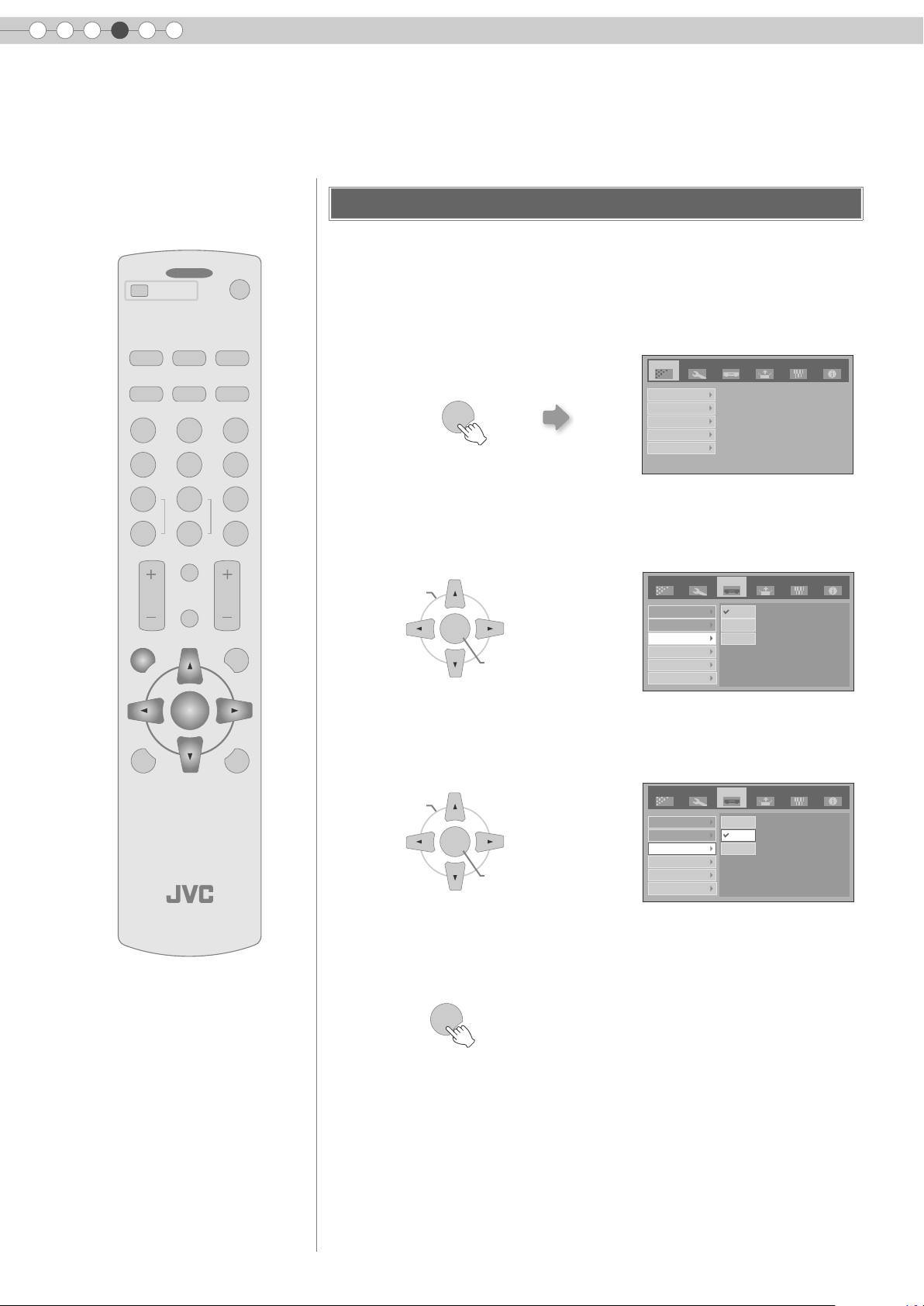
Procedures for Menu Operation
Example:
........ ........
OFF
OPERATE
HDMI 1 COMP.
HDMI 2
ON
When changing “Aspect” from “4:3” to “16:9”
A Display the setting menu
Image
Setup
Source Install. Func. Info.
C
USER
1
COLOR
+
COLOR
-
CONTRAST
MENU
S-VIDEOVIDEO ASPECT
NATURALCINEMA DYNAMIC
N
D
USER
USER
2
3
SHARP
GAMMA
+
SHARP
ENTER
INFO
HIDE
COLOR
-
TEMP
BRIGHT
EXIT
LIGHTTEST
Image Adjust
MENU
Color Temp.
Gamma
Offset
Pixel Adjust
B Select “Source” g “Aspect”
ASELECT
ENTER
BCONFIRM
Image
COMP
HDMI
Aspect
Film Mode
Color System
Black Level
C Set to “16:9”
ASELECT
ENTER
BCONFIRM
Image
COMP
HDMI
Aspect
Film Mode
Color System
Black Level
Setup
Source Install. Func. Info.
4:3
16:9
Zoom
Setup
Source Install. Func. Info.
4:3
16:9
Zoom
24
PROJECTOR
D To end
MENU
Page 25
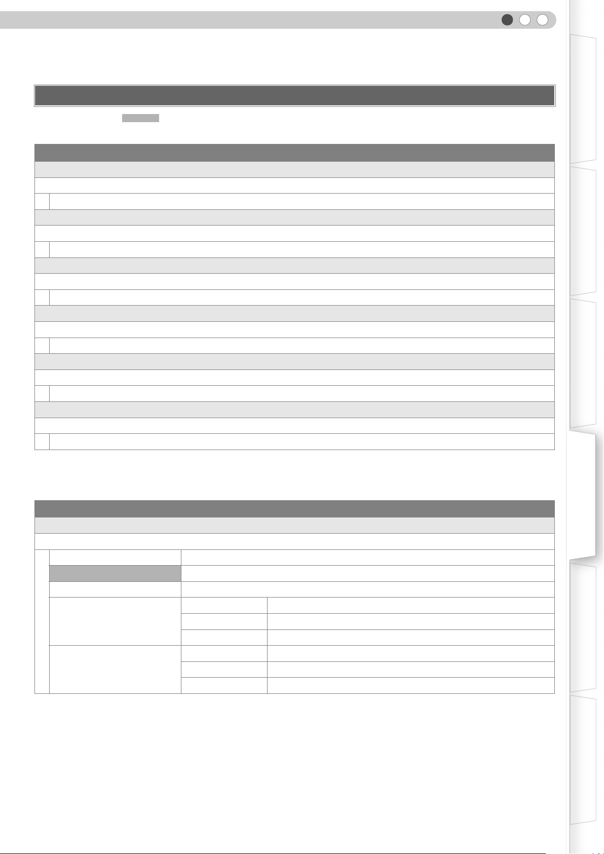
Setting Menu
Item values shown in are factory settings.
z Items that can be configured differ according to the input signals.
Image > Image Adjust
A Contrast
Adjusts the contrast of the projected image.
(Black) b50 to 50 (White)
B Brightness
Adjusts the brightness of the projected image.
(Darken) b30 to 30 (Brighten)
C Color
Adjusts the colour density of the projected image.
(Lighten) b50 to 50 (Darken)
D Tint
Adjusts the hue of the projected image.
(Red) b30 to 30 (Green)
E Sharpness
Adjusts the outline of the projected image.
(Soft) b30 to 30 (Sharp)
F DNR
Adjusts the strength of noise removal of the projected image.
(Weak) 0 to 30 (Strong)
ENGLISH
Getting Started Preparation Basic Operation Settings Troubleshooting Others
z “Contrast”, “Brightness”, “Color” and “Sharpness” can also be configured from the remote control. (pP12)
z “Tint” can only be adjusted when NTSC signals are input to the video or S-video input terminal.
Image > Color Temp.
G Color Temp.
Sets the colour temperature of the projected image.
Low Select this to give a reddish tinge to the image.
Middle Select this to have a balanced image.
High Select this to give a bluish tinge to the image.
Red (Less red) b255 to 0 (More red)
Memory10
Memory20
* The red, green and blue colours can be adjusted and registered respectively.
Green (Less green) b255 to 0 (More green)
Blue (Less blue) b255 to 0 (More blue)
Red (Less red) b255 to 0 (More red)
Green (Less green) b255 to 0 (More green)
Blue (Less blue) b255 to 0 (More blue)
z This setting can also be configured from the remote control. (pP12)
25
Page 26
4
Settings
Setting Menu (Continued)
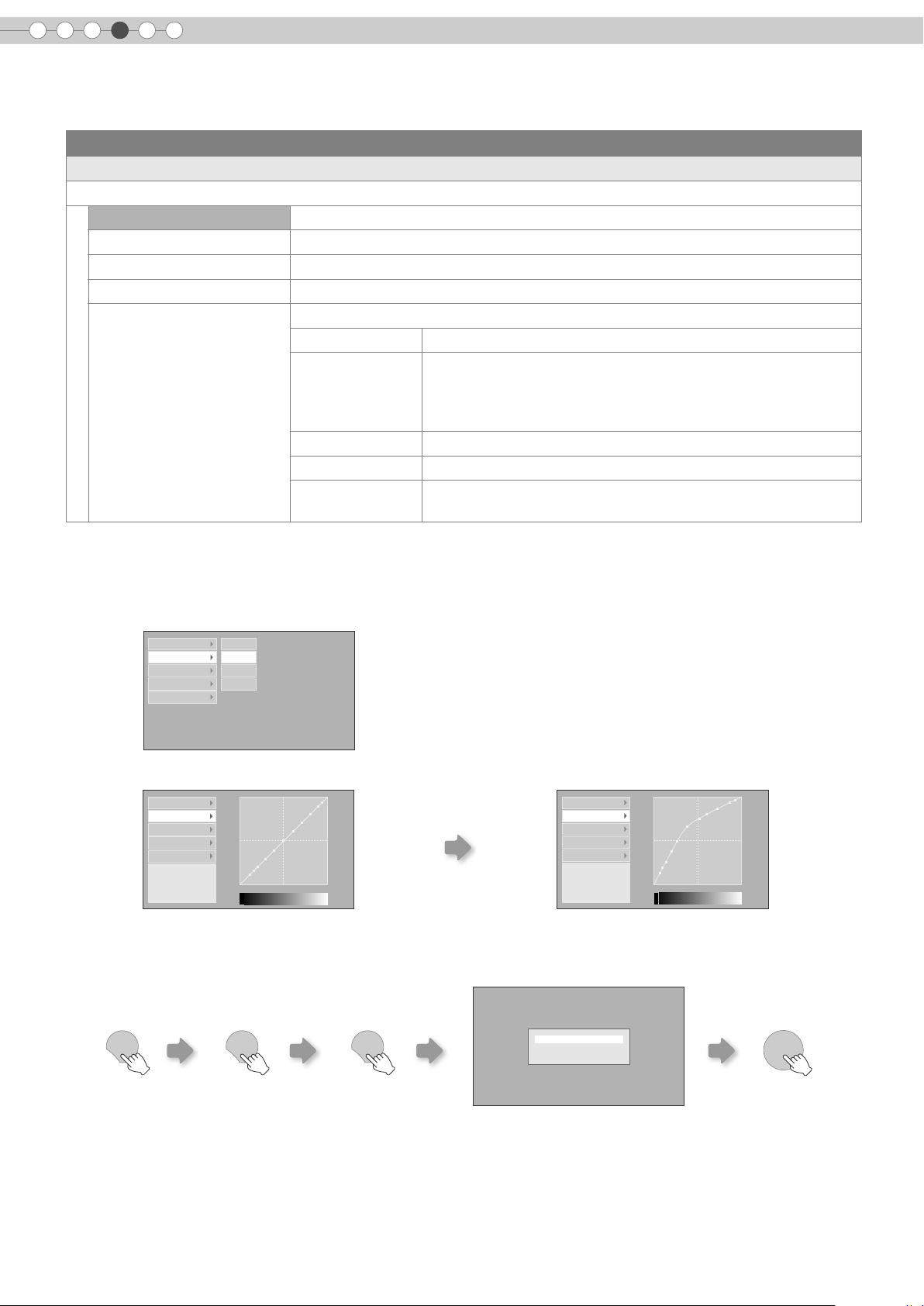
Image > Gamma
H Gamma
Sets the gradation characteristics of the projected image.
Normal For normal circumstances, select this setting.
Theater1 Sets gamma to “Theater1”.
Theater2 Sets gamma to “Theater2”.
Dynamic Select this when in well-lighted areas (such as living room) or when playing games.
Custom
(Gamma Setup)
z
“Normal” is suitable for normal circumstances but other settings can be selected according to your preferences.
z This setting can also be configured from the remote control. (pP12)
*“Gamma Adjust”
A Select the reference gamma curve coefficient (1.8 to 2.6) in “Correction Value”.
B Select the colour to be adjusted in the gamma adjustment screen.
The gamma can be set according to your preferences.
Correction Value The coefficient (1.8 to 2.6) of the gamma curve can be selected.
The gamma curve for the colours (R, G, B) can be adjusted
Gamma Adjust *
separately.
Adjusting “W” will adjust for all “R, G, B” values. Gamma curves
are represented by a “G”.
Save Saves the adjusted gamma data.
Load Loads the gamma data that was saved.
All Reset
Returns the gamma coefficients to the values set by “Correction
Value”.
Correction Value W
Gamma Adjust R
Save G
Load B
All Reset
C Adjust the gamma curve in the gamma curve adjustment screen.
Correction Value
Gamma Adjust
Save
Load
All Reset
Adjustment Point (R)
X: 5 %
Y: 51
1023
512
0 50 100 (%)
Select the point where the gradation (brightness) is to
be adjusted with the H / I buttons.
D To end
EXIT
EXIT EXIT
Correction Value
Gamma Adjust
Save
Load
All Reset
Adjustment Poi nt (R)
X: 5 %
Y: 51
1023
512
0 50 100 (%)
Adjust the gradation (brightness) with the
J / K buttons.
Save gamma data?
Yes : Press [ENTER] button
No : Press [EXIT] button
ENTER
26
z If gamma curve is adjusted repeatedly, calculation errors will be accumulated and the gamma curve may not be able to
revert back to its original form. In that case, select the coefficient in “Correction Value” again or retrieve the previous gamma
data using “Load”.
Page 27
ENGLISH
Image > Offset
I Offset
Adjusts the respective brightness of the red, green and blue colours in dark image areas. (Offset level)
Red (Less red) b60 to 60 (More red)
Green (Less green) b60 to 60 (More green)
Blue (Less blue) b60 to 60 (More blue)
Image > Pixel Adjust
J Pixel Adjust
Makes fine adjustments of 1 pixel unit for each minor colour shift in the horizontal/vertical direction of the image.
Horiz. Red (Moves red to left) 1 to 7 (Moves red to right)
Horiz. Green (Moves green to left) 1 to 7 (Moves green to right)
Horiz. Blue (Moves blue to left) 1 to 7 (Moves blue to right)
Vert. Red (Moves red down) 1 to 5 (Moves red up)
Vert. Green (Moves green down) 1 to 5 (Moves green up)
Vert. Blue (Moves blue down) 1 to 5 (Moves blue up)
Getting Started Preparation Basic Operation Settings Troubleshooting Others
z The horizontal and vertical directions are reversed when the image is flipped to the left or right, or flipped up or down.
z To adjust, use still images with distinct outlines.
z As the adjustments are minor, the effect may be difficult to see for some images.
Setup > Image Profile
K Image Profile
Configures the image profile. (pP34)
Cinema Select this to view images with movie quality in a dark room.
Natural Select this to view projected images with quality as-is in a dark room.
Dynamic Select this to view images with clear quality in a bright room.
User1 Selects image profile registered in “User1”.
User2 Selects image profile registered in “User2”.
User3 Selects image profile registered in “User3”.
z This setting can also be configured from the remote control. (pP12)
Setup > Profile Memory
L Profile Memory
Registers or deletes image profiles.
Save User1 Registers image profile in “User1”.
Save User2 Registers image profile in “User2”.
Save User3 Registers image profile in “User3”.
Clear User1 Returns image profile in “User1” to factory setting (natural).
Clear User2 Returns image profile in “User2” to factory setting (natural).
Clear User3 Returns image profile in “User3” to factory setting (natural).
Reset Cinema Returns image profile in “Cinema” to factory setting.
Reset Natural Returns image profile in “Natural” to factory setting.
Reset Dynamic Returns image profile in “Dynamic” to factory setting.
z “Contrast”, “Brightness”, “Color”, “Sharpness”, “DNR”, “Color Temp.”, “Gamma” and “Offset” are registered in “Image Profile”.
27
Page 28
4
Settings
Setting Menu (Continued)
Setup > Picture Position
M Picture Position
Adjusts the horizontal/vertical position of the projected image.
z
The display position value varies with the input signal.
z This adjustment is available for analogue input signals, or for COMPONENT and HDMI-1/2 input signals when “V-Stretch” is set
to “On”.
Setup > HDMI Input Level
N HDMI Input Level
Configures the input level setting of the HDMI input terminal.
Standard For normal circumstances, select this setting.
Enhanced
z This setting is available only when projecting the HDMI input.
Select this setting when the black-and-white of the projected image is unclear when
RGB video signals are input from DVI devices.
Setup > Mask
O Mask
Masks (Hides) the outer area of the projected image.
2.5% Masks 2.5 % of the screen.
5% Masks 5 % of the screen.
Off No masking.
z Masking is available only when high definition images are input.
Setup > Overscan
P Overscan
Selects whether or not to set overscan for the 4:3 video signals (NTSC, PAL, SECAM, 480i, 576i, 480p and 576p).
Off No overscan.
On Overscans the top, left, bottom and right at 2.5 % each.
z This setting is not available when PC signals are input to HDMI terminal.
Source > COMP
Q COMP
Configures the input signals of the component video input terminals.
Y Pb/Cb Pr/Cr Select this when component video signals are input.
RGB Select this when RGB video signals are input.
SCART
Select this when RGB video signals and sync signals are input from SCART plug for
European market.
28
z This setting is available only when projecting the component video input.
Source > HDMI
R HDMI
Configures the input signals of the HDMI input terminal.
Auto Automatically configures input signals.
YCbCr(4:4:4) Select this when Y Cb Cr (4:4:4) video signals are input.
YCbCr(4:2:2) Select this when Y Cb Cr (4:2:2) video signals are input.
RGB Select this when RGB video signals are input.
z This setting is available only when projecting the HDMI input.
Page 29
ENGLISH
Source > Aspect (When SD video signals are being input)
S Aspect
Configures the screen size (aspect ratio) of the projected image.
4:3 Sets screen size of the projected image to 4:3.
16:9 Sets screen size of the projected image to 16:9.
Zoom Zooms the image.
z This setting can also be configured from the remote control. (pP12, 22)
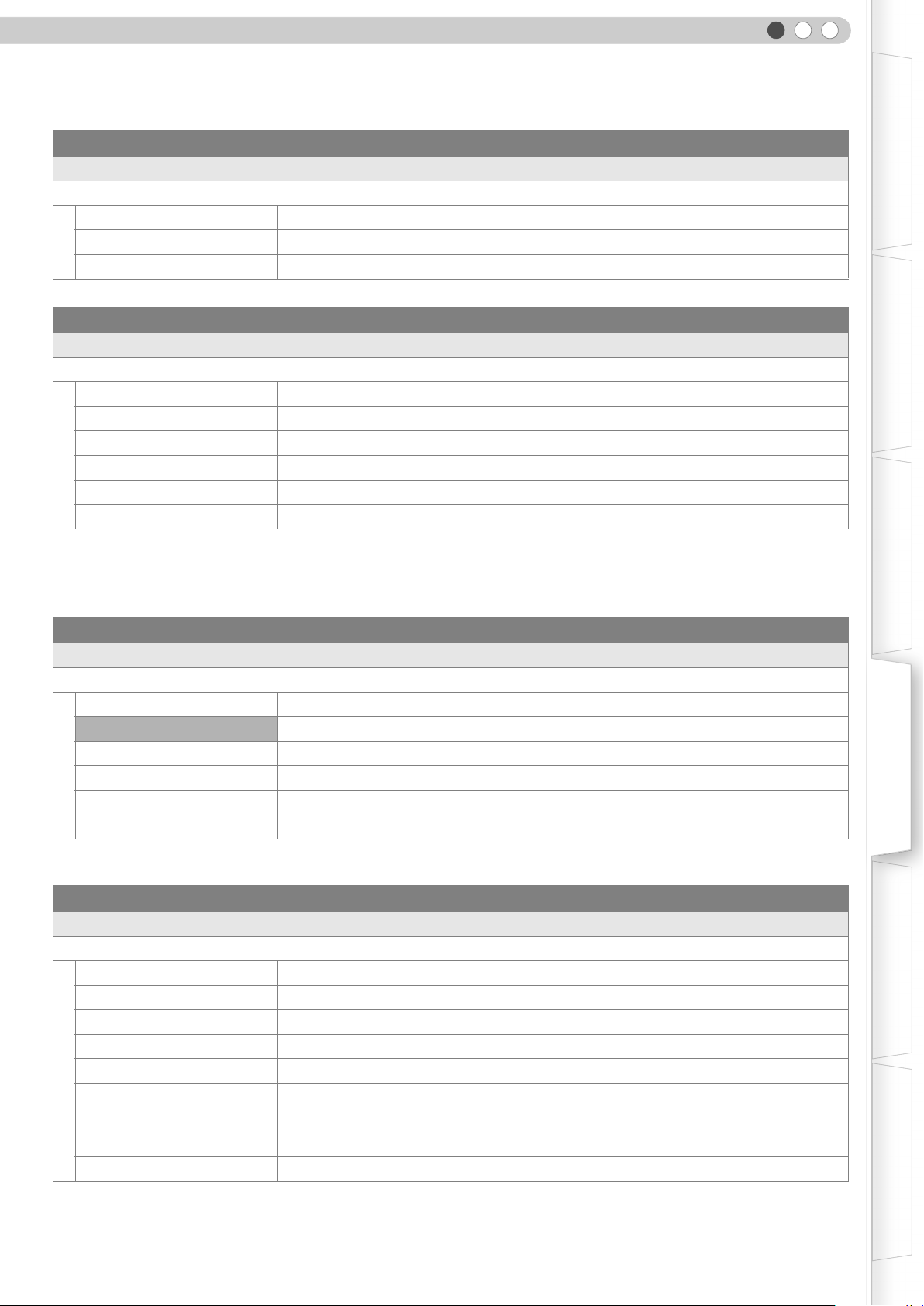
Source > V-Stretch (When HD video signals are being input)
T V-Stretch
When set to “On”, the projected 2.35:1 image will be stretched vertically to the panel resolution.
Off Projects the 2.35:1 image as-is. (Black bands will be displayed on the top and bottom.)
On The projected 2.35:1 image will be stretched vertically to the panel resolution.
Getting Started Preparation Basic Operation Settings Troubleshooting Others
“On”“Off”
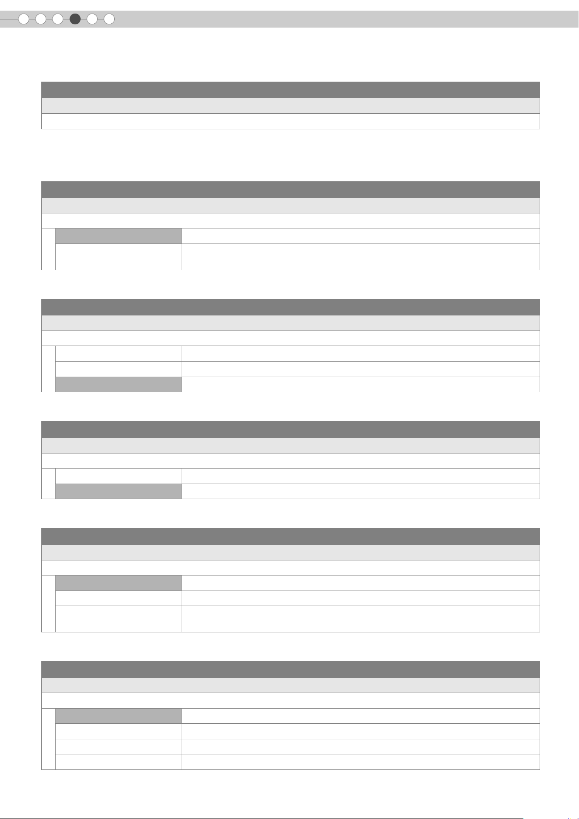
Source > Resize (When PC signals are being input)
U Resize
Sets the screen size of the projected image.
Aspect
Panel Enlarges the PC signal horizontally/vertically, and displays it in 16:9 aspect ratio.
1:1
Enlarges the PC signal horizontally/vertically until it fits the panel height, and displays it
in the original aspect ratio.
Displays the PC signal corresponding to the panel at one dot per pixel ratio. The PC
screen can be shown in the original size.
“Panel”“Aspect” “1:1”
XGA(1024 x 768) XGA(1024 x 768) XGA(1024 x 768)
Source > Film Mode
V Film Mode
Select this to view movies shot on film.
Auto For normal circumstances, select this setting.
Off Select this when you are not watching movies shot on film.
z This setting is not available when PC signals are input to HDMI terminal.
29
Page 30
4
Settings
Setting Menu (Continued)
Source > Color System
W Color System
Configures the colour system.
Auto Configures the colour system automatically.
NTSC Select this when the colour system is NTSC.
NTSC4.43 Select this when the colour system is NTSC4.43.
PAL Select this when the colour system is PAL.
PAL-M Select this when the colour system is PAL-M.
PAL-N Select this when the colour system is PAL-N.
SECAM Select this when the colour system is SECAM.
z
This setting is available only when projecting the video or S-video input.
Source > Black Level
X Black Level
Configures the black level.
0 %
7.5 % Select this when the dark portions of an image appear washed out with the 0 % setting.
Select this when the gradation of the dark portions of an image is indistinct with the
7.5 % setting.
z This setting can only be adjusted when NTSC signals are input to the video or S-video input terminal.
Install. > Menu Position
Y Menu Position
Sets the display position of the menu.
Upper left Displays menu on the upper left of the screen.
Upper centre Displays menu on the upper centre of the screen.
Upper right Displays menu on the upper right of the screen.
Left centre Displays menu on the left centre of the screen.
Centre Displays menu on the centre of the screen.
Right centre Displays menu on the right centre of the screen.
Lower left Displays menu on the lower left of the screen.
Lower centre Displays menu on the lower centre of the screen.
Lower right Displays menu on the lower right of the screen.
Install. > Menu Display
Z Menu Display
Sets the duration for displaying the menu.
15 sec Displays for 15 seconds.
On Always display.
30
Page 31

ENGLISH
Install. > Line Display
a Line Display
Sets whether to display the input when switching input.
5 sec Displays for 5 seconds.
Off Do not display.
Install. > Flip H
b Flip H
Select this when the image is projected from the back of the screen or when the projector is hung from the ceiling.
Off Do not flip image to the left or right.
On Flips image to the left or right.
Install. > Flip V
c Flip V
Select this when the projector is hung from the ceiling.
Off Do not flip image up or down.
On Flips image up or down.
Getting Started Preparation Basic Operation Settings Troubleshooting Others
Install. > High Altitude Mode
d High Altitude Mode
Select this when using the projector in a location of low atmospheric pressure (higher than 900 meters above sea level).
Off Do not activate.
On Activate.
Func. > Back Color
e Back Color
Configures the screen colour displayed when there is no input signal.
Blue Sets screen colour to “Blue”.
Black Sets screen colour to “Black”.
Func. > Sleep Timer
f Sleep Timer
Sets the lapse time before automatically switching to the standby mode when there is no input signal.
15 Switch to standby mode after 15 minutes.
30 Switch to standby mode after 30 minutes.
60 Switch to standby mode after 60 minutes.
Off Do not switch to standby mode.
31
Page 32

4
Settings
Setting Menu (Continued)
Func. > Logo
g Logo
Sets whether to display “Logo” during startup.
Off Do not display.
On Displays for 5 seconds.
Func. > Lamp Power
h Lamp Power
Configures the output of the light-source lamp.
Normal For normal circumstances, select this setting. (170 W)
High Select this when it is difficult to see the image in a bright room. (200 W)
Changing the lamp power will not change the lamp time (lamp life).
z
z The setting cannot be changed within approximately 90 seconds after this unit has been turned on.
z Settings cannot be changed within approximately 60 seconds after they are made.
Func. > Test Pattern
i Test Pattern
Displays 6 types of test patterns. For adjusting the image size (zoom) and the focus. (pP20)
z This can also be displayed from the remote control. (pP12)
Func. > Language
j Language
Sets the language of the menu display.
日本語 Japanese
English English
Deutsch German
Français French
Español Spanish
Português Portuguese
Italiano Italian
Nederlands Dutch
Svenska Swedish
Norsk Norwegian
中文 Chinese (Simplified)
32
Page 33

Info. (During video signal input)
k Input
Displays the currently selected video input.
l Format
Displays the types of the current input video signals.
m H Frequency
This item is grayed out with no value display.
n V Frequency
This item is grayed out with no value display.
o Lamp Time
Displays the accumulated hours of usage of the light-source lamp.
z This can also be displayed from the remote control. (pP12)
Info. (During PC signal input)
p Input
Displays the currently selected PC signal input.
q Resolution
Displays the resolution of the currently inputted PC signal.
r H Frequency
Displays the horizontal frequency of the currently inputted PC signal.
s V Frequency
Displays the vertical frequency of the currently inputted PC signal.
t Lamp Time
Displays the accumulated hours of usage of the light-source lamp.
ENGLISH
Getting Started Preparation Basic Operation Settings Troubleshooting Others
z This can also be displayed from the remote control. (pP12)
33
Page 34

4
Settings
Customizing Projected Images
You can adjust the projected image to a desired image quality and register the adjusted value. (Image
Profile) Besides the default “Cinema”, “Natural” and “Dynamic” settings, there are 3 more types of userdefined settings for image profile.
Changing the Default Image Profile Values
“Contrast”, “Brightness”, “Color”, “Sharpness”, “DNR”, “Color Temp.”, “Gamma” and
........ ........
OFF
OPERATE
HDMI 1 COMP.
HDMI 2
S-VIDEOVIDEO ASPECT
NATURALCINEMA DYNAMIC
N
C
USER
USER
2
1
USER
ON
D
3
“Offset” are registered in the image profile.
A Select the image profile
CINEMACNATURALNDYNAMIC
D
B Adjust image quality
Example: To adjust “Contrast”
COLOR
+
COLOR
-
CONTRAST
MENU
PROJECTOR
SHARP
+
SHARP
-
INFO
HIDE
ENTER
GAMMA
COLOR
TEMP
BRIGHT
a Display the setting menu
MENU
b Select “Image” g “Image Adjust” g “Contrast”
Image
Setup
Source Install. Func. Info.
EXIT
LIGHTTEST
SELECT
ENTER
Image Adjust
Color Temp.
Gamma
Offset
Pixel Adjust
Contrast
Brightness
Color
Tint
Sharpness
DNR
0
0
0
4
0
0
c Adjust the setting
ENTER
ADJUST
Contrast
0
34
d To end the adjustments
EXIT
C Other items can also be adjusted
D To end
z “Contrast”, “Brightness”, “Color”, “Sharpness”, “Color Temp.”
MENU
and “Gamma” can also be adjusted from the remote control.
(pP12)
z To return to the default values, reset the registered settings
with “Profile Memory” in the setting menu. (pP27 - L)
Page 35

Registering User-defined Image Profiles
ENGLISH
Getting Started Preparation Basic Operation Settings Troubleshooting Others
A Select the image profile
USER
USER
1
USER
2
3
B Adjust image quality
z See “Changing the Default Image Profile Values” for procedures on
adjusting the image quality. (pP34)
C To end
MENU
Registering User-defined Image Profiles from the Menu
A Adjust image quality
z See “Changing the Default Image Profile Values” for procedures on
adjusting the image quality. (pP34)
CAUTION
z Adjustment settings of image
quality will not be registered if other
image profiles are selected before
registering these settings.
B Display the setting menu
MENU
C Select “Setup” g “Profile Memory” g
“Save User1”
Image
Setup
ASELECT
ENTER
BCONFIRM
Image Profile
Profile Memory
Picture Position
HDMI Input Level
Mask
Source I nstall. Func. Info .
Save User1
Save User2
Save User3
Clear User1
Clear User2
Clear User3
Reset Cinema
Reset Natura l
Reset Dynamic
D Register the setting
ENTER
Complete
z To return to the default values, reset the registered settings with “Profile
Memory” in the setting menu. (pP27 - L)
35
Page 36

5
Troubleshooting
Troubleshooting
Before sending the unit to your authorized dealer for repair, check the following points.
The following situations are not malfunctions.
You do not need to worry under the following situations if there is no abnormality on the screen.
z Part of the top surface or front of the unit is hot.
z A creaking sound is heard from the unit.
z An operating sound is heard from the internal of the unit.
z Colour smear occurs on some screens.
Perform the following operations when the unit is unable to operate normally due to external static or noises.
A When the unit is in standby mode, pull out the power plug, then insert again.
B Press the power button on the unit to turn on the power again.
A sound may be heard when the lamp is off but there is no danger.
D-ILA device is manufactured using high-precision technology but there may be some missing pixels or pixels that remain
permanently lit up.
Power is not supplied
Is the power cord disconnected? Insert the power cord (plug) firmly. pP20
Remove the power plug when the unit is in standby mode and
Is the lamp cover properly shut?
Is the lamp in Cool Down mode?
close the lamp cover properly. After that, insert the plug
again.
After the Cool Down mode is complete, turn on the power
again.
pP41
pP21
Projected image is dark
Check the lamp time on the information menu. Prepare a new
Is the lamp near exhaustion?
lamp unit or replace as soon as possible when the lamp is near
exhaustion.
pP40 - 42
The unit works when power is turned on but stops abruptly after a few minutes
Are the air inlets and exhaust vent
blocked?
Is the filter dirty? Clean the filter. pP43
Remove the power plug when the unit is in standby mode and
remove any blocking object. After that, insert the plug again.
pP2, 10
Video image does not appear
36
Is the lens cap removed? Remove the lens cap. pP20
Is the correct external input selected? Select the correct external input. pP20
Is the AV device properly connected? Connect the AV device properly. pP14 - 17
Is the power of the AV device turned on? Turn on the power of the AV device and play the video. pP20
Are the correct signals being output from
the AV device?
Is the setting of the input terminal correct?
Is the video image temporarily hidden? Press the [HIDE] button to display the video image again. pP21
Set the AV device properly. pP14 - 17
Set “COMP” and “HDMI” in the setting menu according to the
input signal.
pP28 - Q
pP28 - R
Colour does not appear or looks strange
Is the image correctly adjusted? Adjust “Color” and “Tint” in the setting menu. pP25 - CD
Page 37

ENGLISH
Video image is fuzzy
Is the focus correctly adjusted? Adjust the focus. pP21
Getting Started Preparation Basic Operation Settings Troubleshooting Others
Is the unit placed too near or too far away
from the screen?
Set the unit at a correct distance from the screen. pP18, 19
Video images are missing
Has setting been performed for screen
mask?
Is the display out of position?
Set “Mask” in the setting menu to “Off”. pP23, 28 - O
Alter the “Picture Position” value in the setting menu to ensure
that images are not missing.
pP28 - M
Remote control does not work
Are batteries installed correctly?
Are batteries exhausted? Replace with new batteries. pP13
Is there an obstructive object between the
remote control and remote sensor?
Is the remote control held too far away
from the unit?
Match the polarities (+ or -) correctly when inserting the
batteries.
Remove any obstructive objects. pP13
Hold the remote control closer to the sensor when using. pP13
pP13
Power is cut off suddenly
Has setting been performed for sleep
time?
Set “Sleep Timer” in the setting menu to “Off”. pP31 - f
37
Page 38

5
Troubleshooting
What to Do When These Messages Are Displayed
Message Cause (Details)
No device is connected to the input terminal.
COMP
No input
The input terminal is connected but there is no signal.
gInput the video signals.
HDMI-2
Out of range
Lamp replacement
Lamp replacement
Warning
EXIT
EXIT
A video signal that cannot be used in this unit has been input.
gInput video signals that can be used.
The message is displayed when the accumulated lamp time has exceeded
1900 hours.
To clear the message, press the [EXIT] button.
gGet ready a new lamp unit and replace as soon as possible.
The message is displayed when the accumulated lamp time has exceeded
2000 hours.
The message is displayed each time during projection.
To clear the message, press the [EXIT] button.
gReplace with a new lamp unit and reset the lamp time. (pP40 - 42)
38
Page 39
ENGLISH
About Warning Indicators
The accumulated lamp time or warning mode of this unit is displayed by the indicators.
For information on indicator display during normal operation, see “Controls and Features” (pP10).
Getting Started Preparation Basic Operation Settings Troubleshooting Others
No.
1
2
3
4 Lamp is turned off during projection
5 Lamp cover is removed
6
7
8
9
10
LAMP WARNING
Light on b
Blinking Light on
Indicator
b Light on
Lamp replacement is near (pP40 - 42)
(When accumulated lamp time has exceeded 1900 hours)
Lamp has reached end of life (pP40 - 42)
(When accumulated lamp time has exceeded 2000 hours)
Lamp does not light up and unit is unable to project
There is an error in the circuit operation
(Operation error in microcomputer circuit)
There is an error in the circuit operation
(Operation error in drive circuit)
Internal temperature is abnormally high
(Internal temperature error)
External temperature is high
(External temperature error)
Cooling fan has stopped
(Fan locked)
Content
Actions to Be Taken for Warning Mode
When the unit enters into warning mode (No. 3 to 10), it will automatically stop projection and run the cooling fan for
about 60 seconds.
After the cooling fan has stopped, pull out the power plug from the power outlet.
Then, follow the procedures below.
No. Check Action
z Check that an impact shock has not occurred during
3
4
5
6
7
8
9
10
If the warning indication is displayed again, wait for the cooling fan to stop. Then pull out the power plug from the power outlet.
Call your authorized dealer for repair.
operation.
z Check that the lamp unit and lamp cover are correctly
installed.
z Check that nothing is blocking the air inlets.
z Check that the external temperature is normal.
Turn on the power again.
Leave the unit until it cools down.
After that, turn on the power again.
39
Page 40

5
Troubleshooting
Replacing the Lamp
The lamp is a consumable item. If the image is dark or the lamp is turned off, replace the lamp unit.
When the lamp replacement time approaches, a message is displayed on the screen and the condition is indicated by the
z
indicator. (pP38, 39)
Procedure for Lamp Replacement
CAUTION
z Pull the power plug from the power
outlet. Failure to do so may cause
injuries or electric shocks.
z Do not replace the lamp
immediately after the unit has been
used. Allow a cooling period of 1
hour or more before replacement.
The temperature of the lamp is still
high and this may cause a burn.
z Do not apply shock to the lamp
unit. It may cause lamp blowout.
z Do not use flammable air duster to
clean the internal parts of the unit.
This may cause fire.
MEMO
Usable Lamp Life
...............................
The usable lamp life for this unit is
z
approximately 2000 hours. The
usable lamp life of 2000 hours is
merely the average usable life of
lamps and we do not provide any
guarantee for this figure.
z The lamp life may not reach 2000
hours depending on the operating
conditions.
z When the lamp has reached the
end of its usable life, deterioration
progresses rapidly.
z If the image is dark or the colour
tone is abnormal, replace the lamp
unit as soon as possible.
A Remove the lamp cover
z Remove the screws with a + screwdriver.
B Loosen the screws on the lamp unit
z Loosen the screws with a + screwdriver.
C Pull out the lamp unit
z Grasp the handle and pull out the lamp unit.
40
Purchasing the Lamp Unit
...............................
Please consult your authorized
dealer.
Lamp Unit
Part No. : BHL5009-S
Handle
Page 41

D Install the new lamp unit
E Tighten the screws of the lamp unit
z Fasten the screws with a + screwdriver.
ENGLISH
CAUTION
z Use only genuine replacement
parts for the lamp unit. Also, never
attempt to re-use an old lamp unit.
This may cause a malfunction.
z Do not touch the surface of a new
lamp. This may shorten the lamp
life and cause lamp blowout.
MEMO
After Replacing the Lamp
...............................
z
Do not place the removed lamp
unit at locations reachable by
children or near combustible items.
z Dispose used lamp units in the
same way as fluorescent lamps.
Follow your local community rules
for disposal.
Getting Started Preparation Basic Operation Settings Troubleshooting Others
F Attach the lamp cover
z Insert the top part (with 2 claws) of the lamp cover into the unit.
z Fasten the screws with a + screwdriver.
Claws
41
Page 42

5
Troubleshooting
Replacing the Lamp (Continued)
........ ........
OFF
OPERATE
HDMI 1 COMP.
HDMI 2
S-VIDEOVIDEO ASPECT
NATURALCINEMA DYNAMIC
N
C
USER
USER
COLOR
COLOR
-
CONTRAST
MENU
2
1
SHARP
+
+
SHARP
-
BRIGHT
INFO
HIDE
ENTER
ON
D
USER
3
GAMMA
COLOR
TEMP
EXIT
Resetting Lamp Time
After installing a new lamp unit, reset the lamp time.
A Insert the power plug to the power outlet
STANDBY/ON
Light on (Red)
B Reset lamp time
z Press in the order as shown.
z Press each button within 2-second intervals and press the last button for 2
seconds or more.
EXIT
ENTER
HIDE
LIGHTTEST
WARNING
LAMP
STANDBY/ON
PROJECTOR
CAUTION
z Reset the lamp time only when you
have replaced the lamp.
z Never reset it when the lamp is still
in use. Otherwise, the approximate
standard for gauging replacement
time may be inaccurate and lamp
blowout may occur.
Press for 2 seconds or more
z The [LAMP] indicator and [STANDBY/ON] indicator blink alternately for 3
seconds. After that, the unit switches to standby mode.
42
Page 43

ENGLISH
Cleaning and Replacing the Filter
Clean the filter regularly or air intake efficiency may deteriorate and malfunction may occur.
Getting Started Preparation Basic Operation Settings Troubleshooting Others
A Remove the inner filter
Lift up while pushing the claw
B Clean the filter
CAUTION
z Pull the power plug from the power
outlet.
MEMO
If the filter is damaged or too
dirty to be cleaned
...............................
Replace with a new filter. A dirty
z
filter will dirty the internal parts of
the unit and cause shadows on the
video image.
z To purchase a new filter or when
there is dirt in the internal parts,
consult your authorized dealer.
Inner Filter
Part No. : LC32058-002A
z Wash the filter with water and dry it in a shaded area.
z In extremely soiled cases, use of a neutral detergent is recommended.
Put on rubber gloves when using a neutral detergent.
z After washing the filter with water, make sure that it is completely dry before
reinstalling. Otherwise, electric shocks or malfunctions may occur.
z Do not clean the filter with a vacuum cleaner or air duster. The filter is soft
and may be damaged.
C Reinstall the inner filter
Check that the left and right
claws are locked onto the unit
43
Page 44
Others
6
RS-232C Interface
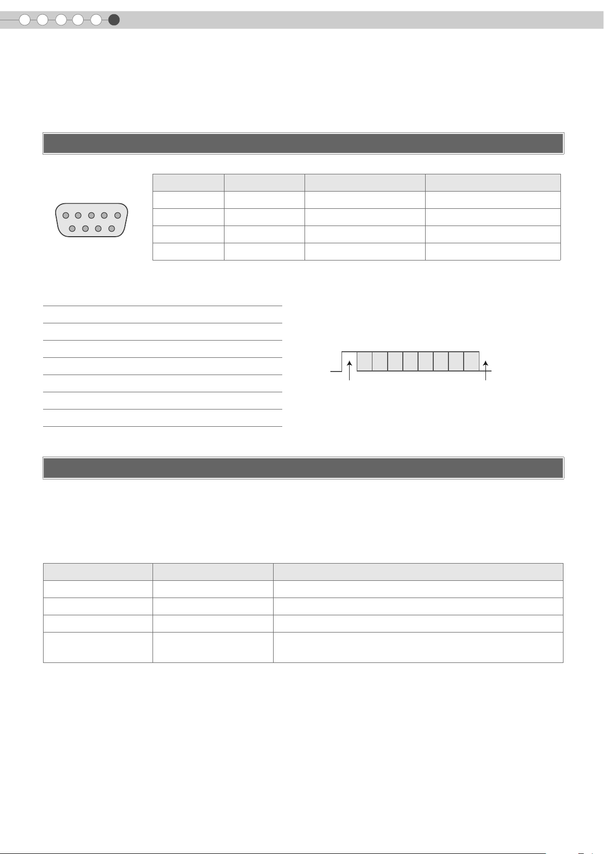
Control of this unit via a computer is possible by connecting the computer to this unit with a RS-232C cross
cable (D-Sub 9 pin).
RS-232C Specifications
Pin No. Signal Operation Signal Direction
2 RxD Receive data This unit PC
3 TxD Transmit data This unit PC
5 GND Signal ground b
1, 4, 6 b 9N/C bb
1
6
This unit
5
9
z PC refers to the controller such as a personal computer.
Mode Non-synchronous
Character Length 8 bit
Parity None
Start Bit 1
Stop Bit 1
Data Rate 19200 bps
Data Format Binary
Command Format
D6 D7D4 D5D2 D3D0 D1
Start Bit Stop Bit
The command between this unit and the computer consists of “Header”, “Unit ID”, “Command”, “Data” and “End”.
z
Header (1 byte), Unit ID (2 bytes), Command (2 bytes), Data (n bytes), End (1 byte)
Header
This binary code indicates the start of communication.
Binary code Type Description
21 Operating command PC This unit
3F Reference command PC This unit
40 Response command This unit PC
06 ACK
This unit PC
(When the command is accepted without error, it returns to PC)
Unit ID
This code specifies the unit. The binary code is fixed at “8901”.
44
Page 45

Command and data
Operating command and data (Binary code)
Command Type Data description
0000 Connection check
5057 Power supply
4950 Input
4754 Gamma table
ENGLISH
Getting Started Preparation Basic Operation Settings Troubleshooting Others
Checks whether communication is available between this unit and
the PC during standby.
During standby
31 : Turns on the power.
During power on
30 : Turns off the power. (Standby mode)
During power on
30 : S-VIDEO
31 : VIDEO
32 : COMP.
36 : HDMI 1
37 : HDMI 2
During power on
30 : Switches to “Normal”.
31 : Switches to “Theater1”.
32 : Switches to “Theater2”.
33 : Switches to “Dynamic”.
34 : Switches to “Custom”.
30 : 1.8 35 : 2.3
31 : 1.9 36 : 2.4
4750 Gamma coefficient
4752 Gamma data (R)
4747 Gamma data (G) Same as gamma data (R).
4742 Gamma data (B) Same as gamma data (R).
5453 Test pattern
5243 Remote Control
32 : 2.0 37 : 2.5
33 : 2.1 38 : 2.6
34 : 2.2
Sets the gradation (0 to 1023) of the output signal in hexadecimal.
The data is 16 bit (2 byte) with the 2 byte data in the high/low order.
During power on
30 : Do not display.
36 : Displays staircase (gray).
Sends the same code as the supplied remote control.
z “Remote control code” (pP47)
45
Page 46

Others
6
RS-232C Interface (Continued)
Reference command and data (Binary code)
Command Type Data description
During standby or power on
30 : Standby mode
5057 Power supply
4950 Input
4754 Gamma table
31 : Power-on mode
32 : During Cool Down mode
34 : Warning mode
During power on
30 : S-VIDEO
31 : VIDEO
32 : COMP.
36 : HDMI 1
37 : HDMI 2
During power on
30 : “Normal”
31 : “Theater1”
32 : “Theater2”
33 : “Dynamic”
34 : “Custom”
30 : 1.8 35 : 2.3
31 : 1.9 36 : 2.4
4750 Gamma coefficient
4752 Gamma data (R) Gradation of the output signal (0 to 1023)
4747 Gamma data (G) Gradation of the output signal (0 to 1023)
4742 Gamma data (B) Gradation of the output signal (0 to 1023)
5453 Test pattern
32 : 2.0 37 : 2.5
33 : 2.1 38 : 2.6
34 : 2.2
During power on
30 : Do not display.
36 : Staircase (gray).
End
This code indicates the end of communication. The binary code is fixed at “0A”.
46
Page 47

Remote control code
z Binary code is sent during communication.
ENGLISH
Getting Started Preparation Basic Operation Settings Troubleshooting Others
Remote control button
name
J 37 33 30 31 USER1 37 33 36 43
K 37 33 30 32 USER2 37 33 36 44
EXIT 37 33 30 33 USER3 37 33 36 45
OPERATE ON 37 33 30 35 HDMI 1 37 33 37 30
OPERATE OFF 37333036 HDMI 2 37333731
HIDE 37 33 31 44 INFO 37 33 37 34
MENU 37 33 32 45 GAMMA 37 33 37 35
ENTER 37 33 32 46 COLOR TEMP 37 33 37 36
I 37 33 33 34 ASPECT 37 33 37 37
H 37 33 33 36 CONTRAST (a) 37333738
VIDEO 37333442 CONTRAST (b) 37333739
S-VIDEO 37333443 BRIGHT (a) 37333741
COMP. 37333444 BRIGHT (b) 37333742
TEST 37 33 35 39 COLOR (a) 37333743
Binary code
Remote control button
name
Binary code
CINEMA 37 33 36 39 COLOR (b) 37333744
NATURAL 37 33 36 41 SHARP (a) 37333745
DYNAMIC 37333642 SHARP (b) 37333746
47
Page 48

Others
6
RS-232C Communication Examples
This section shows the communication examples of RS-232C.
Operating command
Type Command Description
Connection check
Power (On)
Power (Off)
Input (COMP.)
Remote Control
(MENU)
Gamma table
(Custom)
Gamma coefficient
(1.8)
Gamma data
(R)
Test pattern
(Staircase)
PC This unit:21890100000A
This unit PC: 06 89 01 00 00 0A
PC This unit: 21 89 01 50 57 31 0A
This unit PC: 06 89 01 50 57 0A
PC This unit: 21 89 01 50 57 30 0A
This unit PC:06890150570A
PC This unit:2189014950 32 0A
This unit PC: 06 89 01 49 50 0A
PC This unit: 21 89 01 52 43 37 33 32 45 0A
This unit PC:06890152430A
PC This unit:2189014754340A
This unit PC:06890147540A
PC This unit:2189014750300A
This unit PC:06890147500A
PC This unit:21890147520A
This unit PC:06890147520A
PC This unit: 512 bytes of gamma data
This unit PC:06890147520A
PC This unit:2189015453360A
This unit PC:06890154530A
Checks connection
When power is turned on from standby mode
When power is turned off (standby mode)
from power-on mode
When video input is set to component
When the same operation as pressing the
[MENU] button on the remote control is made
When switched to “Custom”
When set to “1.8”
When the red gamma data is set
When staircase (gray) is set
48
Page 49

Reference command
Type Command Description
ENGLISH
Getting Started Preparation Basic Operation Settings Troubleshooting Others
Power (On)
Input (S-VIDEO)
Gamma table
(Custom)
Gamma coefficient
(1.8)
Gamma data
(R)
Test pattern
(Staircase)
PC This unit: 3F 89 01 50 57 0A
This unit PC:06890150 570A
This unit PC:4089015057310A
PC This unit: 3F 89 01 49 50 0A
This unit PC:06890149500A
This unit PC:4089014950300A
PC This unit: 3F 89 01 47 54 0A
This unit PC:06890147540A
This unit PC:4089014754340A
PC This unit: 3F 89 01 47 50 0A
This unit PC:06890147500A
This unit PC:4089014750300A
PC This unit: 3F 89 01 47 52 0A
This unit PC:06890147520A
This unit PC: 512 bytes of gamma data
PC This unit: 3F 89 01 54 53 0A
This unit PC:06890154530A
This unit PC:4089015453360A
When information on power-on mode is
acquired
When information on S-VIDEO input is
acquired
When information on “Custom” is acquired
When information on “1.8” is acquired
When information on red gamma data is
acquired
When information on staircase (gray) is
acquired
49
Page 50

Others
6
Copyright and Caution
About Trademarks and Copyright
z HDMI, HDMI logo and high definition multimedia interface
are trademarks or registered trademarks of HDMI
Licensing LCC.
Caution
D-ILA Device Characteristics
..................................................
Do not project still pictures or pictures that have still
segments for a long period of time. The still parts of the
picture may remain on the screen.
Take special notice of images on the screens of video
games and computer programs.
There is no problem when playing normal video images
such as movies.
When Unit is Unused for a Long Time
..................................................
Prolonged disuse of the unit may effect an error on the
functions. Turn on the power occasionally and operate the
unit.
Usage Environment
..................................................
z Avoid direct exposure of screen to direct sunlight and
illumination. Block light using a curtain. Images can be
well projected by darkening the brightness of the room.
z Do not use this unit in rooms with cigarette smoke or oily
smoke. This may cause the unit to malfunction.
Parts Replacement
..................................................
This unit contains parts (optical part, cooling fan, etc.) that
require replacement to maintain its functioning. The
estimated time for parts replacement varies greatly
depending on the usage and environment. Please consult
your authorized dealer for replacement.
z This product uses Ricoh TrueType fonts manufactured
and sold by Ricoh Co., Ltd.
Maintenance Procedures
..................................................
Dirt on the cabinet
z Gently clean dirt on the cabinet with a soft cloth. In the
case of heavy soiling, soak a cloth in water, wring dry and
wipe, followed by wiping again with a dry cloth.
Pay attention to the following as the cabinet may
deteriorate in condition or paint may come off.
• Do not wipe with thinner or benzene
• Do not spray volatile chemicals like insecticide
• Do not allow prolonged contact with rubber or plastic
products
Dirt in the air inlets
z Use a vacuum cleaner to suck up the dirt. Otherwise, use
a cloth to wipe off the dirt. If dirt is allowed to accumulate
in the air inlets, the internal temperature cannot be
adjusted and this may cause a malfunction.
Dirt on the lens
z Clean the dirt using commercial blowers or lens cleaning
papers for cleaning glasses and cameras.
Do not use fluid-type cleaning agents. This may lead to
peeling of the surface coating film.
Transporting this Unit
..................................................
Before transporting or shipping this unit, attach the buffer
material on the top and bottom of the lens for protection.
Failure to do so may subject the lens to shock causing
damage.
Attach the buffer material after adjusting the lens to the
centre position.
50
Page 51

ENGLISH
Mounting this Unit
Measures to prevent the unit from toppling or dropping should be taken for safety reasons and accident prevention
during emergencies including earthquakes.
When mounting this unit on a pedestal or ceiling, remove the 4 feet on the bottom surface and use all the 4 screw
holes (M5 screws) to mount.
Ceiling
Bottom Surface
4 locations
Getting Started Preparation Basic Operation Settings Troubleshooting Others
Air inlets
Precautions for Mounting
.........................................................................................................
z Special expertise and techniques are required for
mounting this unit. Be sure to ask your dealer or a
specialist to perform mounting.
z Depth of the screw holes (screw length) is 30 mm. Use
screws shorter than 30 mm but longer than 19 mm.
Using other screws will result in malfunctioning or
cause the unit to drop.
z Regardless whether the unit is still under guarantee, JVC
is not liable for any product damage caused by mounting
the unit with non-JVC ceiling fittings or when the
environment is not suitable for ceiling-mount.
z When using the unit hanging from a ceiling, pay attention
to the surrounding temperature. When a heater is in use,
temperature around the ceiling is higher than expected.
z When mounting to a pedestal, ensure sufficient space
(foot height of 21.5 mm or higher) around the unit so that
the air inlets are not blocked.
z Do not tilt this unit more than ±5 degrees from side to side
when using. This may result in uneven colours or
shortening of lamp life.
51
Page 52

Others
6
Specifications
Product Name D-ILA Projector
Model Name DLA-RS2
Display Panel/Size
Projection Lens 2.0x power zoom lens (1.4: 1 to 2.8: 1) (Zoom/Focus: Power)
Light-source Lamp 200 W Ultra-high pressure mercury lamp [Part No.: BHL5009-S]
Screen Size Approx. 60" to 200" (Aspect ratio: 16:9)
Projection Distance Approx. 1.8 m to 12.2 m
Colour System NTSC, NTSC4.43, PAL, PAL-M, PAL-N, SECAM (Auto/Manual switch)
Analogue Video Input Format 480i, 480p, 576i, 576p, 720p/50 Hz, 720p/60 Hz, 1080i/50 Hz, 1080i/60 Hz
Digital Video Input Format
Resolution 1920 dots c 1080 dots
D-ILA device 1 2 /
0.7" (1920 pixels c1080 pixels) c 3 (Total no. of pixels: Approx. 6.22 million)
480i, 480p, 576i, 576p, 720p/50 Hz, 720p/60 Hz, 1080i/50 Hz, 1080i/60 Hz,
1080p/24 Hz, 1080p/50 Hz, 1080p/60 Hz, VGA/60Hz, SVGA/60Hz,
XGA/60Hz, SXGA/60Hz
Input Terminals
Video Input
(VIDEO)
S-video Input
(S-VIDEO)
Component Video Input
(COMPONENT)
HDMI Input
(HDMI 1, HDMI 2)
Power Requirements AC 110 V - 240 V 50/60 Hz
Power Consumption 280 W (Standby mode: 2.7 W)
Operation Environment
Installation Height Below 5000 ft (Approx. 1524 m)
Dimensions (Width c Height c Depth)
1-line, RCA pin jack c 1
1.0 V(p-p), 75 &, synchronous
1-line, mini DIN 4 pin c 1
Y: 1.0 V(p-p), 75 &
C: 0.286 V(p-p), 75 & (NTSC); 0.3 V(p-p), 75 & (PAL)
1-line, RCA pin jack c 3
Y: 1.0 V(p-p), 75 &
, CR/PR: 0.7 V(p-p), 75 &
C
B/PB
2-line, HDMI 19 pin c 2 (HDCP compliant) 3
Temperature: 5 % to 35 %
Humidity: 20 % to 80 % (No condensation)
(Storage Temperature: b10 % to 60 %)
455 mm c 172.5 mm c 418.5 mm
(17 7/8" c 6 7/8" c 16 1/2")
(Excluding lens and protrusion portion)
52
Mass 11.6 kg (25.5 lbs)
Accessories (See Page 9)
*1 D-ILA is the abbreviation for Direct drive Image Light Amplifier.
*2 D-ILA devices are manufactured using extremely high-precision technology. Pixel effectiveness is 99.99 %. Only 0.01 % or less of the pixels
are either missing or would remain permanently lit up.
*3 HDCP is the abbreviation for High-bandwidth Digital Content Protection system.
The image of HDMI input terminal may not be displayed due to HDCP specification change.
• Design and specifications are subject to change without prior notice.
• Please note that some of the pictures and illustrations may have been abridged, enlarged or contextualized in order to aid comprehension.
Images may differ from the actual product.
Page 53

PC compatible signals
ENGLISH
Getting Started Preparation Basic Operation Settings Troubleshooting Others
No. Resolution
1 640 c 480 31.500 60.000 25.200 bb 800 525 640 480
2 640 c 480 31.469 59.940 25.175 bb 800 525 640 480
3 800 c 600 37.879 60.317 40.000 aa 1056 628 800 600
41024c 768 48.363 60.004 65.000 bb 1344 806 1024 768
5 1280 c 1024 63.981 60.020 108.000 aa 1688 1066 1280 1024
Images may not be displayed if the above timings are not met.
fh
[kHz]
fv
[kHz]
dot CLK
[MHz]
Polarity Total no. of
H V
dots
[dot]
Total no. of
lines
[line]
No. of
effective dots
[dot]
effective lines
Dimensions
Top Surface Bottom Surface
300
No. of
[line]
(Unit: mm)
418.512
84
455
Front Left Side
227.5
77
42
172.5
21.5
88.5
23068.5
245.5
149.5
Centre of Lens
53
Page 54

6
Memo
Others
54
Page 55

PROJECTEUR D-ILA
DLA-RS2
FRANÇAIS
Pour commencer Préparation Fonctionnement Réglages Dépannage Autres
MANUEL D’INSTRUCTIONS
Page 56

1
Pour commencer
Importantes Mesures De Sécurité
INFORMATIONS IMPORTANTES
AVERTISSEMENT:
POUR ÉVITER TOUT RISQUE D’INCENDIE OU
D’ÉLÉCTROCUTION, N’EXPOSEZ PAS CET
APPAREIL À LA PLUIE OU À L’HUMIDITÉ.
AVERTISSEMENT:
CET APPAREIL DOIT ETRE MIS A LA TERRE.
ATTENTION:
Pour réduire les risques d’électrocution, ne retirez pas
le couvercle de l’appareil. Référez-vous à un technicien
qualifié.
INFORMATION SUR LE BRUIT MACHINE
(Allemagne uniquementy)
Modification de l’arrêté n°3 sur le bruit machine. GSGV,
18 janvier 1991: Le niveau de pression accoustique à
l’emplacement de l’utilisateur est inférieur ou égal à
70 dB (A) conformément à ISO 7779.
À propos du choix de l’emplacement
N’installez pas le projecteur dans un endroit qui ne peut
pas soutenir son poids en toute sécurité.
Si l’emplacement de l’installation n’est pas suffisamment
solide, le projecteur risque de tomber ou de se renverser
et de blesser quelqu’un.
IMPORTANTES MESURES DE
SÉCURITÉ
L’énergie électrique peut remplir beaucoup de fonctions
utiles. Cet appareil a été conçu et fabriqué pour assurer
votre propre sécurité. Mais UNE UTILISATION
INCORRECTE PEUT ENTRAÎNER UN RISQUE
POTENTIEL D’ÉLECTROCUTION OU D’INCENDIE. Afin
de ne pas annuler les dispositifs de sécurité incorporés
dans cet appareil, observez les règles fondamentales
suivantes pour son installation, son utilisation et sa
réparation. Veuillez lire attentivement ces Importantes
mesures de sécurité avant d’utiliser l’appareil.
- Toutes les instructions de sécurité et de fonctionnement
doivent être lues avant l’utilisation de l’appareil.
- Les instructions de sécurité et de fonctionnement doivent
être conservées à titre d’information.
- Tous les avertissements sur l’appareil et dans le mode
d’emploi doivent être compris et acceptés.
- Toutes les instructions de fonctionnement doivent être
suivies.
- Mettre le projecteur près d’une prise de courant, de façon
à pouvoir le brancher et débrancher facilement.
- Débranchez cet appareil de la prise murale avant de le
nettoyer. Ne pas utiliser de netoyyant ou en aérosol.
Utilisez un chiffon humide pour le nettoyage.
- N’utilisez pas d’accessoires non recommandés par le
fabricant de l’appareil car ils pourraient être dangereux.
- N’utilisez pas ce produit près de l’eau. Ne pas l’utiliser non
plus après l’avoir déplacé d’une basse température à une
température élévée. Cela produit une condensation
d’humidité qui peut entraîner un incendie, une
électrocution ou d’autres dangers.
- Ne placez pas cet appareil sur un chariot, une table ou
tout autre support instable. L’appareil pourraît tomber, et
ainsi blesser gravement un enfant ou un adulte, ainsi
qu’être ui même sérieusement endommagé. L’appareil
doit être monté conformément aux instructions du
fabricant et doit utiliser un support recommandé par le
fabricant.
- Quand vous utilisez l’appareil sur un
chariot, faites attention aux arrêts
brusques, aux forces excessives et aux
surfaces accidentées qui pourraient
causer un renversement de l’appareil,
risquant de l’endommager ou de blesser
l’opérateur.
- Les fentes et les ouvertures du coffret
sont nécessaires pour la ventilation. Elles assurent un
fonctionnement sûr de l’appareil et le protège d’une
surchauffe. Ces ouvertures ne doivent pas être bloquées
ou recouvertes. (Les ouvertures ne doivent jamais être
bloquées en plaçant l’appareil sur un lit, un divan, un tapis
ou une surface similaire. Il ne doit pas être encastré dans
un emplacement comme une bibliothèque ou un bâti sauf
si une ventilation correcte existe et si les instructions du
fabricant ont été respectées.)
-
Afin de permettre une meilleure dissipation de la chaleur,
laissez un espace libre tout autour de cet appareil, tel
qu’illustré ci-dessous. Lorsque cet appareil se trouve dans un
espace dont les dimensions correspondent à celles indiquées
ci-dessous, utilisez un climatiseur pour que la température
soit la même à l’intérieur et à l’extérieur de cet espace.
Au moins 150 mm
Au moins
300 mm
Au moins
150 mm
- Cet appareil doit être alimenté uniquement avec le type
d’alimentation indiquée sur l’étiquette. Si vous n’êtes pas
sûr du type d’alimentation secteur de votre maison,
consultez le revendeur de l’appareil ou votre compagnie
d’électricité.
- Cet appareil est équipé d’une fiche à trois broches. Elle ne
peut être branchée que dans une prise secteur avec mise
à la terre. Si vous ne pouvez pas insérer la fiche dans la
prise, contactez votre électricien afin qu’il installe une
prise correcte. N’essayez pas de défaire le principe de
sécurité de la fiche avec mise à la terre.
- Les cordons d’alimentation doient être positionnés de
façon à ce qu’ils ne soient pas écrasés ou coincés par des
objets placés sous ou contre eux. Faites particulièrement
attention aux cordons au niveau des portes, des fiches et
prises ainsi qu’au niveau de la sortie de l’appareil.
- Pour une meilleure protection pendant un orage ou quand
il est laissé sans surveillance ou n’est pas utilisé pendant
une longue période de temps, débranchez-le de la prise
secteur murale et déconnectez le système de câbles. Cela
évitera qu’il soit endommagé du fait d’un éclair ou d’une
surtension.
Au moins
300 mm
Au moins
200 mm
2
Page 57

FRANÇAIS
Pour commencer Préparation Fonctionnement Réglages Dépannage Autres
- Ne surchargez pas les prises murales, les cordons
prolongateurs ou les prises de courant sur les autres
appareils car cela pourrait entraîner un risaue d’incendie
ou d’électrocution.
- Ne jamais insérer d’objet d’aucune sorte à l’intérier de cet
appareil à travers les ouvertures car ils pourraient toucher
des points de tension dangeureuse ou créer un court
circuit qui pourrait entraîner un incendie ou une
éléctrocution. Ne jamais verser de liquide d’aucune sorte
sur l’appareil.
- N’essayez pas de réparer cet appareil vous-même car
l’ouvrir ou retirez les couvercles peut vous exposer à des
tensions dangeureuses ou à d’autres dangers.
Référezvous à un personnel qualifié pour toute réparation.
- Débranchez l’appareil de la prise secteur murale et
contactez un réparateur qualifié dans les conditions
suivantes:
a) Quand le cordon ou la fiche d’alimentation secteur est
endomagé.
b) Si un liquide à coulé ou si un objet est tombé l’intérieur de
l’appareil.
c) Si l’appareil a été exposé à la pluie ou à l’eau.
d) Si l’appareil ne fonctionne pas normalement en suivant les
instructions de fonctionnement. Ajustez uniquement les
commandes couvertes par le mode d’emploi, car un
ajustement incorrect des commandes peut endommager
l’appareil et demandera souvent beaucoup de temps à un
technicien qualifié pour ramener l’appareil en état de
fonctionnement normal.
e) Si le produit est tombé ou a été endommagé de n’importe
quelle autre façon.
f) Quand l’appareil montre un changement évident dans ses
performances, cela indique qu’il doit être réparé.
- Quand le remplacement des pièces est nécessaire,
assurezvous que le réparateur a utilisé les pièces de
rechange spécifiées par le fabricant ou possédant les
mêmes caractéristiques que la pièce originale. Un
remplacement non autorisé peut entraîner in incendie, une
éléctrocution ou autres dangers.
-
Après que cet appareil a subi une réparation ou un
entretien, demandez au réparateur de réaliser les
vérifications de sécurité pour déterminer si l’appareil est en
état de fonctionnement correct.
- L’appareil doit être placé à plus de trente centimètres de
sources de chaleur, comme un radiateur, un accumulateur
de chaleur, un fourneau ou tout autre appareil
(amplificateurs inclus) produisant de la chaleur.
- Lors d’un raccordement avec un magnétoscope ou un
lecteur de DVD, vous devez mettre cet appareil hors
tension pour éviter tout choc électrique.
- Ne placez pas de produits combustibles derrière le
ventilateur de refroidissement. Par exemple, du tissu, du
papier, des allumettes, une bombe aérosol ou un briquet à
gaz qui présentent des dangers particuliers s’ils sont
chauffés.
- Ne regardez pas dans l’objectif de projection quand la
lampe du projecteur est allumée. Une exposition des yeux
à une forte lumière peut affaiblir votre vue.
- Ne regardez pas à l’intérieur de l’appareil au travers de
évents (orifices de ventilation), etc. Ner regardez pas
directement la lampe de projection en ouvrant le coffret
pendant que celle-ci est allumée. La lampe de projection
émet aussi des rayons ultrviolets et la lumière est si forte
que votre vue pourrait être affaiblie.
- Ne pas laisser tomber, frapper ou autrement endommager
la source de lumière (module lampe). La source de
lumière peut se briser et entraîner des blessures. Ne
jamais utiliser de lampe endommagée. Si la source de
lumière est cassée, demandez à votre revendeur
d’eefectuer la réparation. Des fragments provenants d’une
lampes brisée pourraient causer des blessures.
- La lampe utiliser dans ce projecteur est une lampe au
mercure sous haute pression. Faire attention lorsque cette
lampe doit être jetée. S’il y a quelque chose que vous ne
comprenez pas, contactez votre revendeur.
- N’effectuez pas de “montage au plafond” du projecteur
dans endroit soumis à beaucoup de vibrations. Les
fixations pourraient se défaire du fait des vibrations
causant ainsi la chute de l’appareil et une éventuelle
blessure physique.
- Utilisez uniquement le cordon fourni conçu pour cet
appareil afin d’éviter tout choc éléctrique.
*NE LAISSEZ PAS une personne non qualifiée
installer l’appareil.
Demandez au revendeur d’installer l’appareil (par
exemple, la fixation au plafond) car cela demande des
connaissances et des techniques spéciales. Si
l’installation est réalisée par une personne non
qualifiée, cela pourrait entraîner des blessures
personnelles ou une éléctrocution.
3
Page 58

1
Pour commencer
Importantes Mesures De Sécurité (Suite)
CONNEXION ELECTRIQUE
La tension d’alimentation secteur de cet appareil est de
110 V – 240 V CA. N’utilisez que le cordon
d’alimentation désigné par nos revendeurs pour la
sécurité et la compatibilité électromagnétique (EMC).
Assurez- vous que le cordon d’alimentation utilisé pour
le projecteur correspond bien au type de prise de votre
pays. Consultez votre revendeur.
Cordon díalimentation
\
AVERTISSEMENT:
Ne débranchez pas la fiche principale de cet
appareil.
Si la fiche existante ne convient pas aux prises de
courant de votre maison ou si le cordon est trop court
pour atteindre une prise de courant, procurez-vous un
cordon prolongateur ou un adapteur de sécurité
approuvé ou consultez votre revendeur.
Si la fiche secteur etait coupée, jetez la prise
immédiatement, pour éviter tout danger d’électrocution
par une connexion accidentelle à l’alimentation secteur.
Si la nouvelle fiche secteur doit être adapté, suivez les
instructions données ci-dessous.
AVERTISSEMENT:
CET APPAREIL DOIT ETRE MIS A LA TERRE.
IMPORTANT:
Les codes couleurs des fils du cordon d’alimentation de
cet appareil sont les suivants:
Vert et jaune : Terre
Bleu : Neutre
Marron : Sous tension
Comme ces couleurs ne correspondent peut être pas
avec les couleurs identifiant les bornes de votre fiche.
Procédez comme suit:
Le fil coloré en vert et jaune doit être connecté à la
borne marquée M par la lettre E ou le symbole de terre
ou de couleur vert et jaune.
Le fil qui est coloré en bleu doit être connecté à la borne
qui est marqué par la lettre N ou de couleur noire.
Le fil qui est coloré en marron doit être connecté à la
borne qui est marquée de la lettre L ou de couleur
rouge.
4
Page 59

FRANÇAIS
Cher(e) client(e),
Cet appareil est conforme aux directives et normes européennes en vigueur concernant la compatibilité
électromagnétique et à la sécurité électrique.
Représentant européen de la société Victor Company of Japan, Limited :
JVC Technical Services Europe GmbH
Postfach 10 05 04
61145 Friedberg
Allemagne
Pour commencer Préparation Fonctionnement Réglages Dépannage Autres
5
Page 60

Principales caractéristiques
.
Compatible avec de
nombreux appareils
numériques
...............................................
z Livré avec un double HDMI terminal
permettant la transmission numérique de
signaux haute définition. (pP14)
6
Page 61

.
Superbes images sur grand écran
.................................................................
z Profitez d’images vidéo lisses à résolution élevée, sans
scintillement, grâce à la résolution complète en haute
définition de 1920 c 1080 pixels. (pP20)
Pour commencer Préparation Fonctionnement Réglages Dépannage Autres
Parfait dans tous les locaux
........................................................
z Livré avec une fonction de décalage de l’objectif:
80 % verticalement et 34 % horizontalement.
(pP18)
7
Page 62

1
.
.
.
.
.
.
Contenu
Pour commencer
Pour commencer
..................................................
Importantes Mesures De Sécurité...........................2
Principales caractéristiques...................................6
Contenu..............................................................8
Comment lire ce manuel/
Accessoires/Accessoires facultatifs ......................9
À propos de ce manuel....................................................9
Vérifier les accessoires.....................................................9
Accessoires facultatifs ......................................................9
Commandes et fonctionnalités.............................10
Comment utiliser la télécommande ......................13
Mise en place des piles ..................................................13
Portée efficace de la télécommande ................................13
Préparation
..................................................
Sélectionner les périphériques à raccorder...........14
Raccordements ..................................................15
Raccordement via câble vidéo et câble S-vidéo................15
Raccordement via un câble vidéo composante .................15
Raccordement par câble HDMI.......................................16
Raccordement par câble de conversion HDMI-DVI ...........16
Raccordement via un câble SCART-RCA (Péritel-RCA) ......17
Raccordement via câble vidéo RVB .................................17
Dépannage
..................................................
Dépannage.......................................................36
Que faire lorsque ces messages s’affichent ..........38
À propos des indicateurs d’alertes ......................39
Mesures à prendre en cas d’avertissement ...................... 39
Remplacement de la lampe.................................40
Procédure pour le remplacement de la lampe.................. 40
Réinitialisez la durée de vie de la lampe ......................... 42
Nettoyage et remplacement du filtre....................43
Autres
..................................................
Interface RS-232C .............................................44
Caractéristiques RS-232C.............................................. 44
Format de commande.................................................... 44
Exemples de communication RS-232C ............................ 48
Droits d’auteurs et mise en garde........................50
À propos des marques de commerce et droits d’auteurs ... 50
Mises en garde............................................................. 50
Fixation de l’appareil .................................................... 51
Caractéristiques.................................................52
Dimensions................................................................... 53
Installation du projecteur et de l’écran .................18
Taille de l’écran et distance de projection ........................19
Fonctionnement
..................................................
Projection des images ........................................20
Fonctions utiles pendant la projection ..................22
Réglage de la taille de l’écran ........................................22
Masquage de la zone périphérique d’une image .............22
Réglages
..................................................
Menu de configuration.......................................24
Procédures d’utilisation du menu ....................................24
Menu de configuration...................................................25
Personnalisation des images projetées.................34
Modification des valeurs par défaut du profil d’image......34
Enregistrement des profils d’image définis
par l’utilisateur............................................................35
Enregistrement des profils d’image définis par
l’utilisateur à partir du menu ........................................35
8
Page 63

FRANÇAIS
Comment lire ce manuel/ Accessoires/Accessoires facultatifs
À propos de ce manuel
Ce manuel décrit principalement le mode de fonctionnement de l’appareil
N
C
USER
1
COLOR
+
COLOR
-
CONTRAST
MENU
USER
SHARP
SHARP
INFO
HIDE
D
USER
2
3
au moyen de la télécommande.
z
Les boutons de la télécommande sont appelés [Nom du bouton].
z Les éléments à sélectionner sur le menu sont décrits comme “Élément à
GAMMA
+
COLOR
TEMP
-
BRIGHT
EXIT
sélectionner”.
Conventions utilisées dans ce manuel
Décrit les limites des fonctions ou de leur utilisation.
Indique une information “bonne à savoir”.
Pour commencer Préparation Fonctionnement Réglages Dépannage Autres
Décrit les précautions à observer au cours du fonctionnement.
ENTER
LIGHTTEST
pP9
Indique les pages de renvoi.
Les boutons à utiliser sont colorés avec
une teinte plus foncée.
Vérifier les accessoires
N
O
.
.
..
.
.
.
.
E
AT
R
PE
O
P
.
M
.
..
O
.
.
C
.
.
T
F
C
F
O
z Le manuel d’instructions ainsi que les autres documents imprimés sont également inclus.
C
E
P
MI
2
S
I
A
A
M
N
D
H
DY
D
O
E
D
I
AL
V
1
-
ER
R
I
S
S
U
M
3
U
D
AT
H
N
A
N
M
O
M
E
A
D
I
G
V
SER
EMA
2
U
O
N
L
I
C
E
CO
P
T
C
R
A
H
+
S
SER
P
B
1
U
AR
-
SH
R
O
L
+
CO
O
F
N
R
I
T
O
S
L
A
-
CO
TR
N
CO
Télécommande
R
P
M
T
H
G
I
R
T
I
X
E
E
D
I
H
R
HT
E
IG
U
L
T
N
EN
M
E
T
ES
T
Piles AAA
(pour confirmation du fonctionnement)
Câble d’alimentation
(2 m)
Accessoires facultatifs
Veuillez vérifier auprès de votre revendeur officiel pour les détails.
Lampe de rechange: BHL5009-S (Lampe)
z
z Filtre de rechange: LC32058-002A (Filtre interne)
9
Page 64

1
Pour commencer
Commandes et fonctionnalités
Pour mettre au point.
Pour régler la taille de l’image.
z Utilisation de la télécommande. (pP20)
AVERTISSEMENT
z Ne tournez pas l’objectif avec vos mains.
z Cet appareil est livré avec une plaque de protection coussinant l’objectif. Retirer la
plaque de protection avant utilisation.
z Ne pas jeter cette plaque, la conserver pour une utilisation ultérieure. (pP50)
Face avant/Côté gauche
Couvercle de la lampe
(pP40)
Récepteur de commande à
distance
(pP13)
Entrées d’air
Capuchon de
l’objectif
Évent de sortie d’aération
Face arrière/Dessus
10
Récepteur de commande à distance (pP13)
Pour brancher le câble d’alimentation (pP20)
Page 65

FRANÇAIS
Pour commencer Préparation Fonctionnement Réglages Dépannage Autres
Témoin allumé (rouge):
Mode veille (Stand-by)
Témoin allumé (vert):
Au cours de la projection
Clignotant (vert):
l’image est temporairement
cachée
(pP21)
Clignotant (rouge):
Mode de refroidissement (pP21)
Pour brancher une entrée
(pP20)
Pour afficher le menu
(pP24)
STANDBY/ON
MENU
WARNING
LAMP
STANDBY/ON
INPUT
HIDE
ENTER
Témoin allumé (rouge):
Mode alerte (pP39)
Témoin allumé/clignotant (orange):
Témoin d’avertissement de lampe
(pP39)
Pour allumer/éteindre
Pour cacher l’image temporairement
(pP21)
EXIT
Pour retourner au menu précédent
Pour sélectionner ou confirmer
Face inférieure
Pieds: Vous pouvez ajuster la hauteur (0 à 5 mm) en tournant les pieds.
Entrées d’air/Filtre (pP43)
Pour régler la position de l’image (pP19)
11
Page 66

1
Pour commencer
Commandes et fonctionnalités (Suite)
Télécommande
Pour éteindre l’appareil
Sélectionner le mode d’entrée (pP20)
Changer le profil image
(pP34)
Pour régler la densité de la couleur
(pP34)
Pour régler le contraste
(pP34)
Pour afficher les informations
........ ........
OFF
COLOR
COLOR
CONTRAST
MENU
OPERATE
HDMI 1 COMP.
C
USER
1
+
-
HDMI 2
S-VIDEOVIDEO ASPECT
NATURALCINEMA DYNAMIC
N
USER
2
SHARP
+
SHARP
-
BRIGHT
INFO
HIDE
ON
D
USER
3
GAMMA
COLOR
TEMP
EXIT
Pour allumer l’appareil
Pour régler la taille de l’écran
(pP22)
Définir le facteur de contraste (gamma)
(pP34)
Pour régler le contour de l’image
(pP34)
Définir la température de la couleur
(pP34)
Pour régler la luminosité
(pP34)
Pour cacher l’image temporairement
(pP21)
12
Pour afficher le menu
(pP24)
Pour afficher les mires
Pour ajuster la taille de l’image
(zoom) et mise au point. (pP20)
ENTER
PROJECTOR
Pour retourner au menu précédent
LIGHTTEST
Pour illuminer les boutons de la
télécommande
Pour sélectionner ou confirmer
Page 67

FRANÇAIS
Comment utiliser la télécommande
Mise en place des piles
12 3
z S’il est nécessaire de rapprocher la télécommande du projecteur pour qu’elle fonctionne, cela signifie que les piles sont
faibles. Quand cela survient, remplacer les piles. Insérer les piles selon les +- marques.
z Assurez-vous d’insérer l’extrémité - en premier.
z Si une erreur survient lors de l’utilisation de la télécommande, retirer les piles et attendre 5 minutes. Remettre en place les
piles et faire fonctionner la télécommande.
Pour commencer Préparation Fonctionnement Réglages Dépannage Autres
Portée efficace de la télécommande
En dirigeant la télécommande en
direction de l’appareil
En visant le récepteur de commande à
z
distance avec la télécommande, s’assurer
que le capteur situé à l’avant ou l’arrière de
l’appareil se trouve à une distance de moins
de 7 m.
z Si la télécommande ne fonctionne pas
correctement, se rapprocher de l’appareil.
En cas de réflexion à partir de l’écran
S’assurer que la distance totale A - entre
z
l’appareil et l’écran - plus B - entre la
télécommande et l’écran - ne dépasse pas
7m.
z Dans la mesure où le rendement des signaux
réfléchis depuis la télécommande diffèrent
selon le type d’écran utilisé, la distance de
fonctionnement peut diminuer.
Écran
Cet appareil
20°
20°
20°
20°
B
B
30°
30°
30°
30°
30°
30°
30°
20°
20°
20°
N
O
.
.....
..
E
T
A
20°
20°
20°
R
E
P
O
.
MP
..
O
...
C
..
T
F
C
F
C
E
I
O
P
M
2
S
I
A
A
M
N
D
Y
H
D
D
O
E
L
D
I
A
R
V
1
-
E
R
S
S
U
MI
3
U
T
D
A
H
N
A
N
M
O
M
E
A
D
I
G
A
R
V
E
M
S
R
E
2
U
O
P
N
L
I
M
O
C
E
C
P
T
C
R
T
A
H
H
+
S
G
I
R
E
R
S
P
B
1
U
R
A
H
-
S
R
O
L
O
+
C
O
F
N
R
I
T
O
S
L
A
O
T
C
R
I
X
T
E
E
ON
D
I
C
H
T
R
H
G
E
I
U
L
N
NT
E
M
E
T
S
E
T
Télécommande
30°
30°
30°
30°
Cet appareil
A
A
ON
...
.
.
..
E
T
RA
E
P
O
..
..
..
..
.
F
F
O
P
M
O
C
2
I
M
D
H
1
I
M
D
T
H
C
ASPE
C
I
EO
M
D
A
I
V
N
Y
S-
D
L
A
EO
R
D
I
U
V
T
A
D
N
A
M
INE
C
N
R
E
S
C
U
3
R
E
S
U
2
R
E
S
A
U
M
M
1
A
G
P
R
A
H
S
+
R
O
L
R
O
O
L
C
O
C
P
+
M
E
T
P
R
A
H
S
T
-
H
G
I
R
R
B
O
L
O
C
-
T
S
A
R
T
N
O
F
O
N
I
C
E
D
I
H
T
I
X
E
U
N
E
M
R
E
NT
E
T
H
G
I
L
T
S
E
T
Télécommande
13
Page 68

2
C
O
M
PONEN
T
Préparation
Sélectionner les périphériques à raccorder
z Ne pas allumer avant d’avoir fini le raccordement.
z Les procédures de raccordement peuvent varier selon le type de périphérique utilisé. Pour les détails, se reporter au manuel
d’instructions du périphérique à raccorder.
z Pour une sortie audio, raccorder l’appareil à un amplificateur.
z Il est possible que les images ne s’affichent pas, dépendamment des câbles et périphériques qui restent à brancher.
Utilisez un câble compatible HDMI (vendu séparément), présentant le logo HDMI.
z Dépendamment de la dimension du couvercle du connecteur du câble à branché, il se peut qu’il soit impossible de brancher
cet appareil.
Enregistreur DVD Lecteur DVD
Pour raccordement via une borne HDMI (pP16)
Pour raccordement via une borne RS-232C
Pour raccordement via une bornes de vidéo composante (pP15)
HDMI 2 HDMI 1 RS-232C
S-VIDEO
VIDEO
Y CB/PB CR/PR
SYNC
GBR
COMPONENT
Pour raccordement via une borne vidéo (pP15)
Pour raccordement via une borne S-vidéo (pP15)
Bloc-notes PC
Magnétoscope et camescope
14
Page 69

Raccordements
S-3
C
M
PONEN
T
C
B
/
P
BCR
/
P
R
G
B
R
S
VID
E
O
S3C
VID
E
O
S
Y
N
C
Raccordement via câble vidéo et câble S-vidéo
Cet appareil
FRANÇAIS
Pour commencer Préparation Fonctionnement Réglages Dépannage Autres
Vers la borne d’entrée vidéo
HD RS-232C
S-VIDEO
VIDEO
SYNC
OMPONENT
Y CB/PBCR/P
Y
GBR
R
Câble vidéo
(vendu séparément)
Câble S-vidéo (vendu séparément)
Vers la borne d’entrée S-vidéo
Raccordement via un câble vidéo composante
Sortie vidéo
Magnétoscope et camescope
Sortie S-vidéo
Cet appareil
HD RS-232C
S-VIDEO
VIDEO
Y CB/PB CR/PR
SYNC
GBR
OMPONENT
Bornes de sortie vidéo composante
Câble vidéo composante
(vendu séparément)
Vers les bornes d’entrée vidéo composante
z Régler “Composantes” dans le menu de configuration sur “Y Pb/Cb Pr/Cr”. (pP28 - Q)
Lecteur DVD
(Rouge)
C
R/PR
CB/PB(Bleu)
Y(Vert)
15
Page 70

2
S
O
RS-232
C
C
OPO
O
S
C
C/C
/
G
S
O
RS232
C
COO
O
S
C
C/C
/
G
Préparation
Raccordements (Suite)
Raccordement par câble HDMI
Cet appareil
HDMI 2 HDMI 1 RS-232C
S-VIDEO
VIDEO
Y CB/PB CR/PR
Y
SYNC
GBR
COMPONENT
E
R
Câble HDMI (vendu séparément)
Vers borne d’entrée
HDMI 1 ou HDMI 2
Raccordement par câble de conversion HDMI-DVI
Enregistreur DVD
Borne de sortie HDMI
Cet appareil
MDMI 2 MDMI 1 RS-232C
S-VIDEO
Vers borne d’entrée
HDMI 1 ou HDMI 2
COMPONENT
VIDEO
Y CB/PB CR/PR
SYNC
GBR
Câble de conversion HDMI-DVI (vendu séparément)
Bloc-notes PC
Borne de sortie DVI
16
Page 71

Raccordement via un câble SCART-RCA (Péritel-RCA)
S
VID
E
O
S3C
S
VID
E
O
S3C
VID
E
O
S
Y
N
C
Cet appareil
FRANÇAIS
Pour commencer Préparation Fonctionnement Réglages Dépannage Autres
HD RS-232C
S-VIDEO
-
VIDEO
Y CB/PB CR/PR
GBR
SYNC
OMPONENT
Câble SCART-RCA
(vendu séparément)
Vers les bornes d’entrée vidéo RVB et signal sync.
z Régler “Composantes” dans le menu de configuration sur “SCART”. (pP28 - Q)
Raccordement via câble vidéo RVB
Cet appareil
Lecteur DVD pour le marché européen
Borne SCART
HD RS-232C
S-VIDEO
VIDEO
Y CB/PB CR/PR
SYNC
GBR
OMPONENT
Périphérique équipé d’une sortie RVB
Bornes de sortie vidéo RVB
Câble vidéo RVB
R (Rouge)
(vendu séparément)
B (Bleu)
Vers les bornes d’entrée vidéo RVB
G (Vert) (inclus un signal sync.)
z Régler “Composantes” dans le menu de configuration sur “RVB”. (pP28 - Q)
z Pour plus de renseignements sur les signaux d’entrée, consultez “Caractéristiques”. (pP52)
17
Page 72

2
Préparation
Installation du projecteur et de l’écran
Installer cet appareil et l’écran. Placez cet appareil et l’écran perpendiculairement l’un par rapport à l’autre.
Si ce n’est pas le cas, cela peut entraîner une distorsion trapézoïdale de l’image projetée.
A Installer le projecteur et l’écran
Position gauche/droite
*Centrage vertical (0 % de décalage dans l’axe vertical)
Approximativement 34 % (au maximum) de l’image projetée
(Tourner la molette vers la droite pour obtenir le maximum)
Approximativement 34 % (au maximum) de l’image projetée
(Tourner la molette vers la gauche pour obtenir le maximum)
Position dans l’axe vertical
*Centrage horizontal (0 % de décalage dans l’axe horizontal)
Approximativement 80 % (au maximum) de l’image projetée
(Tourner la molette vers la gauche pour obtenir le maximum)
Approximativement 80 % (au maximum) de l’image projetée
(Tourner la molette vers la droite pour obtenir le maximum)
18
Changer la portée de l’image projetée
80%
34% 34%
80%
MDMI2 MDMI1 RS-232C
COMPONENT
S-VIDEO
VIDEO
Y CB/PBCR/P
R
SYNC
GBR
Page 73

FRANÇAIS
B Régler de telle façon que l’image projetée soit au centre de l’écran
Pour commencer Préparation Fonctionnement Réglages Dépannage Autres
Déplace l’image vers la
gauche ou la droite
Déplace l’image vers le
haut ou le bas
CONSEILS
z L’ajustement peut se faire facilement en bougeant
l’image vers le haut et vers le centre.
z Il peut être nécessaire de régler “Décalage pixels” dans le menu de configuration après avoir réglé la position de l’image.
(pP27 - J)
Taille de l’écran et distance de projection
Déterminer la distance entre l’objectif et l’écran pour obtenir la taille d’écran que vous souhaitez.
Cet appareil utilise un objectif avec zoom automatique x2,0 pour la projection.
Taille de l’écran projeté par rapport à la distance de projection
Taille de l’écran de
projection
(en diagonale)
Rapport de format
16:9
Distance approximative de
projection
W (Large) à T (Télé)
Taille de l’écran de
projection
(en diagonale)
Rapport de format
16:9
Distance approximative de
projection
W (Large) à T (Télé)
60"
(Environ 1,52 m)
70"
(Environ 1,78 m)
80"
(Environ 2,03 m)
90"
(Environ 2,29 m)
100"
(Environ 2,54 m)
110"
(Environ 2,79 m)
120"
(Environ 3,05 m)
130"
(Environ 3,30 m)
z
Les distances de projection du tableau ci-dessus dont fournies uniquement à titre indicatif. Veuillez en tenir compte lors de
l’installation du projecteur.
Environ
1,78 m
Environ
2,09 m
Environ
2,40 m
Environ
2,71 m
Environ
3,01 m
Environ
3,32 m
Environ
3,63 m
Environ
3,93 m
à
à
à
à
à
à
à
à
Environ
3,63 m
Environ
4,24 m
Environ
4,86 m
Environ
5,47 m
Environ
6,08 m
Environ
6,70 m
Environ
7,31 m
Environ
7,93 m
140"
(Environ 3,56 m)
150"
(Environ 3,81 m)
160"
(Environ 4,06 m)
170"
(Environ 4,32 m)
180"
(Environ 4,57 m)
190"
(Environ 4,83 m)
200"
(Environ 5,08 m)
Environ
4,24 m
Environ
4,55 m
Environ
4,86 m
Environ
5,16 m
Environ
5,47 m
Environ
5,78 m
Environ
6,08 m
à
à
à
à
à
à
à
Environ
8,54 m
Environ
9,16 m
Environ
9,77 m
Environ
10,38 m
Environ
11,00 m
Environ
11,61 m
Environ
12,23 m
z Pour régler l’installation, utiliser une image projetée au format 16:9.
19
Page 74

3
.
Fonctionnement
Projection des images
Ce chapitre décrit les opérations de base pour projeter des images entrantes sur l’écran.
Préparation
......................................................................
........ ........
OFF
OPERATE
HDMI 1 COMP.
HDMI 2
ON
z Retirez le capuchon de l’objectif.
A Branchez la prise du câble d’alimentation
dans la prise électrique
C
USER
1
COLOR
+
COLOR
-
CONTRAST
MENU
S-VIDEOVIDEO ASPECT
NATURALCINEMA DYNAMIC
N
USER
SHARP
SHARP
INFO
HIDE
ENTER
D
USER
2
3
GAMMA
+
COLOR
TEMP
-
BRIGHT
EXIT
LIGHTTEST
A Raccordez le câble à cet
appareil
B Raccordez à la prise
d’alimentation
A
Câble d’alimentation
(Fourni)
B Allumer l’appareil
ON
z Vous pouvez également appuyer sur le bouton [STANDBY/ON] pour
allumer l’appareil. (pP11)
STANDBY/ON
C Projetez l’image
a Sélectionner le mode d’entrée
COMP.HDMI 2HDMI 1
STANDBY/ON
Témoin allumé (rouge)
B
Témoin allumé (vert)
20
WARNING
LAMP
STANDBY/ON
PROJECTOR
VIDEO S-VIDEO
z Vous pouvez également sélectionner la mode d’entrée en appuyant
sur le bouton [INPUT] sur l’appareil. (pP11)
b Affichez les images du périphérique sélectionné
D Réglez la position de l’écran de projection
z Voir “Installation du projecteur et de l’écran” pour les procédures de
réglage de la position. (pP18)
E Réglez la taille de l’image (zoom) et la mise
au point
a Afficher la mire (hachurage croisé)
TEST
Appuyez à plusieurs
reprises
Page 75

b Réglez la mise au point
FRANÇAIS
Pour commencer Préparation Fonctionnement Réglages Dépannage Autres
ENTER
Appuyez pendant
1 seconde ou plus
Mise au point
Ajustez en conséquence en
appuyant sur les boutons haut
et bas
c Réglez la taille de l’image (zoom)
ENTER
Zoom
Ajustez en conséquence en
appuyant sur les boutons haut
et bas
z Bascule entre “Mise au point” et “Zoom” chaque fois que vous appuyez sur
le bouton [ENTER].
ENTER
d Pour terminer
EXIT
CONSEILS
Vous pouvez masquer
temporairement l’image
...............................
Vous pouvez masquer
temporairement l’image.
HIDE
STANDBY/ON
Le témoin vert clignote
lorsque l’image est
masquée
z Appuyez sur le bouton [HIDE] pour
afficher à nouveau l’image.
z L’appareil ne peut être éteint
lorsque l’image est temporairement
masquée.
F Éteignez l’appareil
Alors qu’un écran de confirmation est affiché
STANDBY/ON
Mode de refroidissement
STANDBY/ON
z L’appareil ne peut être éteint avant au moins 90 secondes suivant sa mise
sous tension. Débutez l’opération uniquement après 90 secondes.
z Vous pouvez également appuyer sur le bouton [STANDBY/ON] pour
éteindre l’appareil. (pP11)
z Remettez le capuchon de l’objectif après emploi pour protéger l’objectif de
la poussière.
z Débranchez le câble d’alimentation lorsque vous n’utilisez pas l’appareil
pour une longue période.
OFF
OFF
Clignotant (rouge)
Témoin allumé (rouge)
NOTE
À propos du mode de
refroidissement
...............................
Le mode de refroidissement est
z
une fonction permettant le
refroidissement de la lampe
pendant environ 60 secondes
suivant la fin de la projection.
Cette fonction empêche la
déformation ou l’endommagement
des pièces internes de l’appareil
du fait de la surchauffe de la
lampe. Elle empêche également un
éclatement ou un
raccourcissement prématuré de la
durée de vie de la lampe.
z Au cours de la phase de
refroidissement, l’indicateur
[STANDBY/ON] clignote en rouge.
z Suivant la phase de
refroidissement, l’appareil retourne
automatiquement en mode veille.
z Ne débranchez pas la prise
d’alimentation durant la phase de
refroidissement. Cela pourrait
raccourcir la durée de vie de la
lampe et entraîner un mauvais
fonctionnement.
21
Page 76

3
Fonctionnement
Fonctions utiles pendant la projection
Vous pouvez modifier la taille de l’écran de l’image projetée ou masquer la zone entourant une image dont la
qualité de la zone périphérique s’est détériorée.
Réglage de la taille de l’écran
L’image projetée peut être réglée pour correspondre à la taille d’écran la plus
........ ........
OFF
OPERATE
ON
appropriée (rapport de format).
HDMI 1 COMP.
HDMI 2
S-VIDEOVIDEO ASPECT
NATURALCINEMA DYNAMIC
N
C
USER
COLOR
COLOR
CONTRAST
MENU
USER
2
1
SHARP
+
+
SHARP
-
-
BRIGHT
INFO
HIDE
ENTER
D
USER
3
GAMMA
COLOR
TEMP
EXIT
LIGHTTEST
ASPECT
La taille de l’écran peut également être réglée à partir de “Aspect” dans le menu de
z
4:3 16:9 ZOOM
configuration. (pP29 - S)
z Si des images haute définition sont entrées, le réglage “Etirement V” sera
disponible. (pP29 - T)
z Si des signaux PC sont entrés, le réglage “Redimension” sera disponible.
(pP29 - U)
Image source et image projetée par différents paramètres de taille
d’écran
Image source
SDTV(4:3)
4:3 16:9 Zoom
Rapport de format:
Identique
Taille d’écran la plus
appropriée
Format de l’écran
Rapport de format:
Paysage
L’image est étirée
horizontalement
Rapport de format:
Identique
Le haut et le bas de
l’image sont
manquants
22
PROJECTOR
SDTV(4:3)
L’image a été
enregistrée au format
paysage (bandes
Rapport de format:
Identique
Une petite image est
projetée
Rapport de format:
Paysage
L’image est étirée
horizontalement
Rapport de format:
Identique
Taille d’écran la plus
appropriée
noires en haut et en
bas) avec le logiciel
de DVD
En fonction de l’image source, la sélection de “4:3” peut se traduire par un
z
étirement vertical de l’image alors qu’en sélectionnant “16:9”, vous obtiendrez la
taille d’écran la plus appropriée.
Masquage de la zone périphérique d’une image
Les images dont la qualité de la bordure externe est détériorée peuvent être
projetées en masquant (cachant) le pourtour de l’image projetée.
Page 77

A Projetez l’image
FRANÇAIS
Pour commencer Préparation Fonctionnement Réglages Dépannage Autres
B Masquez l’image
a Affichez le menu de configuration
MENU
b Sélectionnez “Réglages” g “Masque”
ASÉLECTIONNER
ENTER
BCONFIRMER
iImage dont la qualité de la bordure
externe est détériorée.
Réglages
Image
Qualité image
Temp. Couleur
Gamma
Gain
Décalage pixels
Profils image
Profils mémoire
Position d’image
Niveau entrée HDMI
Masque
Surbalayage
Source Installation Fonction Info
RéglagesImage Source Installation Fonction Info
2.5%
5%
Arrêt
NOTE
z Le masquage est disponible
uniquement pour des images haute
définition.
c Établissez une valeur de masque
ASÉLECTIONNER
ENTER
BCONFIRMER
Exemple:
Lorsque la valeur “Masque” est
changée à partir de “Arrêt” g “5%”
C Pour terminer
MENU
RéglagesImage Source Installation Fonction Info
Profils image
Profils mémoire
Position d’image
Niveau entrée HDMI
Masque
Surbalayage
2.5%
5%
Arrêt
23
Page 78

4
Réglages
Menu de configuration
Les images projetées peuvent être réglées pour correspondre au format souhaité en changeant les
paramètres par défaut.
Procédures d’utilisation du menu
Exemple:
........ ........
OFF
OPERATE
HDMI 1 COMP.
HDMI 2
ON
Si vous changez “Aspect” de “4:3” à “16:9”
A Affichez le menu de configuration
Réglages
Image
Source Installation Fonction Info
C
USER
1
COLOR
+
COLOR
-
CONTRAST
MENU
S-VIDEOVIDEO ASPECT
NATURALCINEMA DYNAMIC
N
D
USER
USER
2
3
SHARP
GAMMA
+
SHARP
ENTER
INFO
HIDE
COLOR
-
TEMP
BRIGHT
EXIT
LIGHTTEST
Qualité image
MENU
Temp. Couleur
Gamma
Gain
Décalage pixels
B Sélectionnez “Source” g “Aspect”
Réglages
ASÉLECTIONNER
ENTER
BCONFIRMER
Image
Composantes
HDMI
Aspect
Film
Système Couleur
Niveau de noir
Source Installation Fonction Info
4:3
16:9
Zoom
C Réglez sur “16:9”
Réglages
ASÉLECTIONNER
ENTER
BCONFIRMER
Image
Composantes
HDMI
Aspect
Film
Système Couleur
Niveau de noir
Source Installation Fonction Info
4:3
16:9
Zoom
24
PROJECTOR
D Pour terminer
MENU
Page 79

Menu de configuration
Les valeurs des éléments présentées en sont les réglages prédéfinis en usine.
z Les éléments pouvant être configurés varient selon les signaux entrants.
Image > Qualité image
A Contraste
Règle le contraste de l’image projetée.
(Noir) b50 à 50 (Blanc)
B Luminosité
Règle la luminosité de l’image projetée.
(Assombrit) b30 à 30 (Éclaircit)
C Couleur
Règle la densité de la couleur de l’image projetée.
(Éclaircit) b50 à 50 (Assombrit)
D Teinte
Règle la teinte de l’image projetée.
(Rouge) b30 à 30 (Vert)
E Détail
Règle la netteté de l’image projetée.
(Douce) b30 à 30 (Nette)
F DNR
Règle le niveau de suppression de bruit (interférences) de l’image projetée.
(Faible) 0 à 30 (Fort)
FRANÇAIS
Pour commencer Préparation Fonctionnement Réglages Dépannage Autres
z “Contraste”, “Luminosité”, “Couleur” et “Détail” peuvent également être configurés à partir de la télécommande. (pP12)
z “Teinte” peut uniquement être réglé lorsque les signaux NTSC entrent par la borne vidéo ou S-vidéo.
Image > Temp. Couleur
G Temp. Couleur
Fixe la température de la couleur de l’image projetée.
Bas Sélectionnez pour donner une teinte rougeâtre à l’image.
Moyen Sélectionnez pour avoir une image équilibrée.
Haut Sélectionnez pour donner une teinte bleuâtre à l’image.
Rouge (Moins rouge) b255 à 0 (Plus rouge)
Mémoire10
Mémoire20
* Les couleurs rouge, vert et bleu peuvent être réglées et enregistrées indépendamment.
Vert (Moins vert) b255 à 0 (Plus vert)
Bleu (Moins bleu) b255 à 0 (Plus bleu)
Rouge (Moins rouge) b255 à 0 (Plus rouge)
Vert (Moins vert) b255 à 0 (Plus vert)
Bleu (Moins bleu) b255 à 0 (Plus bleu)
z Ce paramétrage peut également être configuré à partir de la télécommande. (pP12)
25
Page 80

4
Réglages
Menu de configuration (Suite)
Image > Gamma
H Gamma
Fixe les caractéristiques de dégradé de l’image projetée.
Normal Dans les cas habituels, choisir ce paramétrage.
Théâtre1 Fixe le facteur de contraste à “Théâtre1”.
Théâtre2 Fixe le facteur de contraste à “Théâtre2”.
Dynamique
Personnalisé
(Réglage Gamma)
“Normal” convient aux cas habituels, mais d’autres réglages peuvent être sélectionnés selon vos préférences.
z
z Ce paramétrage peut également être configuré à partir de la télécommande. (pP12)
*“Réglage Gamma”
A Sélectionnez le coefficient de la courbe gamma de référence (1,8 à 2,6) dans “Réglage de Base”.
B Sélectionnez la couleur que vous désirez ajuster dans l’écran d’ajustement gamma.
Sélectionnez cette option pour les zones bien éclairées (comme les salons) ou lorsque
vous jouez à des jeux.
Le gamma peut être ajusté selon vos préférences.
Réglage de Base
Vous pouvez choisir le coefficient (1,8 à 2,6) de la courbe gamma
(facteur de contraste).
Vous pouvez ajuster séparément la courbe gamma (facteur de
Réglage Gamma *
contraste) des couleurs (R, G, B).
Ajuster “W” ajustera toutes les valeurs “R, G, B”. Les courbes
gamma sont représentées pas la lettre G.
Enregistrer Sauvegarde les données gamma ajustées.
Charger Charge les données gamma préalablement sauvegardées.
RAZ
Ramène les coefficients gamma aux valeurs réglées à “Réglage
de Base”.
Réglage de Base W
Réglage Gamma R
Enregistrer G
Charger B
RAZ
C Ajustez la courbe gamma dans l’écran d’ajustement courbe gamma.
Réglage de Base
Réglage Gamma
Enregistrer
Charger
RAZ
Point de réglage (R)
X: 5 %
Y: 51
1023
512
0 50 100 (%)
Sélectionnez le point où la gradation (luminosité)
sera ajustée au moyen des boutons H / I.
D Pour terminer
EXIT
EXIT EXIT
Réglage de Base
Réglage Gamma
Enregistrer
Charger
RAZ
Point de réglage (R)
X: 5 %
Y: 51
1023
512
0 50 100 (%)
Ajustez la gradation (luminosité) au moyen des
boutons J / K.
Voulez vous enregistrez les données Gamma ?
Oui : Appuyer sur le bouton [ENTER]
Non : Appuyer sur le bouton [EXIT]
ENTER
26
z Si la courbe gamma est ajustée plusieurs fois, des erreurs de calcul s’accumuleront et il est possible que la courbe gamma
ne puisse revenir pas à sa forme originale. Dans ce cas, sélectionnez une fois de plus le coefficient dans “Réglage de
Base” ou récupérez les données gamma précédentes avec “Charger”.
Page 81

FRANÇAIS
Image > Gain
I Gain
Règle la luminosité respective du rouge, du vert et du bleu dans les zones sombres de l’image. (Niveau de décalage)
Rouge (Moins rouge) b60 à 60 (Plus rouge)
Vert (Moins vert) b60 à 60 (Plus vert)
Bleu (Moins bleu) b60 à 60 (Plus bleu)
Image > Décalage pixels
J Décalage pixels
Fait des ajustements fins de 1 pixel pour chaque couleur déplacée dans la direction horizontale/verticale de l’image.
Rouge horiz. (Décale le rouge vers la gauche) 1 à 7 (Décale le rouge vers la droite)
Vert horiz. (Décale le vert vers la gauche) 1 à 7 (Décale le vert vers la droite)
Bleu horiz. (Décale le bleu vers la gauche) 1 à 7 (Décale le bleu vers la droite)
Rouge vert. (Décale le rouge vers le bas) 1 à 5 (Décale le rouge vers le haut)
Vert vert. (Décale le vert vers le bas) 1 à 5 (Décale le vert vers le haut)
Bleu vert. (Décale le bleu vers le bas) 1 à 5 (Décale le bleu vers le haut)
Pour commencer Préparation Fonctionnement Réglages Dépannage Autres
z Les directions horizontales et verticales sont inversées lorsque l’image est tournée vers la gauche ou la droite, ou renversée
vers le haut ou le bas.
z Pour effectuer le réglage, utilisez des images statiques aux contours nets.
z Lorsque les réglages sont minimes, l’effet peut être difficile à voir sur certaines images.
Réglages > Profils image
K Profils image
Configure le profil de l’image. (pP34)
Cinéma Sélectionnez pour voir des images ayant une qualité cinéma dans une pièce sombre.
Naturel
Dynamique Sélectionnez pour voir des images nettes, de qualité, dans une pièce éclairée.
Util. 1 Sélectionne le profil de l’image enregistré dans “Util. 1”.
Util. 2 Sélectionne le profil de l’image enregistré dans “Util. 2”.
Util. 3 Sélectionne le profil de l’image enregistré dans “Util. 3”.
Sélectionnez pour voir des images projetées avec une qualité naturelle dans une pièce
sombre.
z Ce paramétrage peut également être configuré à partir de la télécommande. (pP12)
Réglages > Profils mémoire
L Profils mémoire
Enregistre ou supprime les profils d’image.
Enreg. util. 1 Enregistre le profil d’image dans “Util. 1”.
Enreg. util. 2 Enregistre le profil d’image dans “Util. 2”.
Enreg. util. 3 Enregistre le profil d’image dans “Util. 3”.
Suppr. util. 1
Suppr. util. 2
Suppr.util. 3
Réinit. Cinéma Ramène le profil d’image enregistré dans “Cinéma” aux paramètres préréglés en usine.
Réinit. Naturel Ramène le profil d’image enregistré dans “Naturel” aux paramètres préréglés en usine.
Réinit. Dynamique
Ramène le profil d’image enregistré dans “Util. 1” aux paramètres préréglés en usine
(naturels).
Ramène le profil d’image enregistré dans “Util. 2” aux paramètres préréglés en usine
(naturels).
Ramène le profil d’image enregistré dans “Util. 3” aux paramètres préréglés en usine
(naturels).
Ramène le profil d’image enregistré dans “Dynamique” aux paramètres préréglés en
usine.
z “Contraste”, “Luminosité”, “Couleur”, “Détail”, “DNR”, “Temp. Couleur”, “Gamma” et “Gain” sont enregistrés dans “Profils
image”.
27
Page 82

4
Réglages
Menu de configuration (Suite)
Réglages > Position d’image
M Position d’image
Règle la position horizontale/verticale de l’image projetée.
z
La valeur de la position d’affichage varie selon le signal entrant.
z Cet ajustement est disponible pour les signaux d’entrée analogiques, ou pour les signaux d’entrées COMPONENT et HDMI-1/
2 lorsque “Etirement V” est réglé à “Marche”.
Réglages > Niveau entrée HDMI
N Niveau entrée HDMI
Configure le réglage de niveau d’entrée de la borne d’entrée HDMI.
Standard Dans les cas habituels, choisir ce paramétrage.
Amélioré
z Ce paramétrage est disponible uniquement lors de la projection d’une entrée HDMI.
Sélectionnez ce paramétrage quand le noir et blanc de l’image projetée n’est pas clair
lorsque les signaux vidéo RVB proviennent d’appareils DVI.
Réglages > Masque
O Masque
Masque (cache) la zone externe de l’image projetée.
2.5% Masque 2,5 % de l’écran.
5% Masque 5 % de l’écran.
Arrêt Aucun masquage.
z Le masquage est disponible uniquement pour des images haute définition.
Réglages > Surbalayage
P Surbalayage
Sélectionne ou non pour régler le surbalayage des signaux vidéo 4:3 (NTSC, PAL, SECAM, 480i, 576i, 480p et 576p).
Arrêt Pas de surbalayage.
Marche Surbalaies le dessus, la gauche, le bas et la droite à 2,5 % chacun.
z Ce paramétrage n’est pas disponible lorsque les signaux PC sont entrés dans le terminal HDMI.
Source > Composantes
Q Composantes
Configure les signaux entrants de la bornes d’entrée vidéo en composante.
Y Pb/Cb Pr/Cr Sélectionnez lors de l’entrée de signaux vidéo composante.
RVB Sélectionnez lorsque les signaux vidéo RVB sont entrants.
SCART
Sélectionnez lorsque des signaux vidéo RVB et des signaux sync. entrent en
provenance d’une prise SCART (Péritel) pour le marché européen.
28
z Ce paramétrage est disponible uniquement lors de la projection d’une entrée vidéo en composante.
Source > HDMI
R HDMI
Configure les signaux entrants de la borne d’entrée HDMI.
Auto Configure automatiquement les signaux entrants.
YCbCr(4:4:4) Sélectionnez lorsque les signaux vidéo Y Cb Cr (4:4:4) sont entrants.
YCbCr(4:2:2) Sélectionnez lorsque les signaux vidéo Y Cb Cr (4:2:2) sont entrants.
RVB Sélectionnez lorsque les signaux vidéo RVB sont entrants.
z Ce paramétrage est disponible uniquement lors de la projection d’une entrée HDMI.
Page 83

FRANÇAIS
Source > Aspect (Lorsque les signaux vidéo SD ont été entrés)
S Aspect
Configure la taille d’écran (rapport de format) de l’image projetée.
4:3 Fixe la taille d’écran de l’image projetée à 4:3.
16:9 Fixe la taille d’écran de l’image projetée à 16:9.
Zoom Agrandit l’image (zoom).
z Ce paramétrage peut également être configuré à partir de la télécommande. (pP12, 22)
Source > Etirement V (Lorsque les signaux vidéo HD ont été entrés)
T Etirement V
Si elle est réglée à “Marche”, l’image 2,35:1 projetée sera étirée verticalement à la résolution de l’affichage.
Arrêt Projette l’image 2,35:1 telle quelle. (Des bandes noires apparaîtront en haut et en bas.)
Marche L’image 2,35:1 projetée sera étirée verticalement à la résolution de l’affichage.
Pour commencer Préparation Fonctionnement Réglages Dépannage Autres
Source > Redimension (Lorsque les signaux vidéo PC ont été entrés)
U Redimension
Règle la taille de l’écran pour l’image projetée.
Aspect
Panel
1:1
Agrandit le signal PC horizontalement/verticalement jusqu’à ce qu’il ait atteint la hauteur
de l’affichage, et l’affiche selon le rapport de format original.
Agrandit le signal PC horizontalement/verticalement, et l’affiche à un rapport d’affichage
de 16:9.
Affiche le signal PC correspondant à l’affichage à un point par rapport de pixel. L’écran
de l’ordinateur peut être affiché à sa taille originale.
“Panel”“Aspect” “1:1”
“Marche”“Arrêt”
XGA(1024 x 768) XGA(1024 x 768) XGA(1024 x 768)
Source > Film
V Film
Sélectionnez pour visionner des films enregistrés sur film.
Auto Dans les cas habituels, choisir ce paramétrage.
Arrêt Sélectionnez lorsque vous ne regardez pas des images de film sur film.
z Ce paramétrage n’est pas disponible lorsque les signaux PC sont entrés dans le terminal HDMI.
29
Page 84

4
Réglages
Menu de configuration (Suite)
Source > Système Couleur
W Système Couleur
Configure le système de couleurs.
Auto Configure automatiquement le système de couleurs.
NTSC Sélectionnez lorsque le système de couleurs est NTSC.
NTSC4.43 Sélectionnez lorsque le système de couleurs est NTSC4.43.
PAL Sélectionnez lorsque le système de couleurs est PAL.
PAL-M Sélectionnez lorsque le système de couleurs est PAL-M.
PAL-N Sélectionnez lorsque le système de couleurs est PAL-N.
SECAM Sélectionnez lorsque le système de couleurs est SECAM.
z
Ce paramétrage est disponible uniquement lors de la projection d’une entrée vidéo ou S-vidéo.
Source > Niveau de noir
X Niveau de noir
Configure le niveau de noir.
0 %
7.5 %
Sélectionnez cette option lorsque la gradation de la partie sombre d’une image est floue
avec un réglage de 7,5 %.
Sélectionnez cette option lorsque les parties sombres d’une image paraissent claires
avec un réglage à 0 %.
z Ce paramétrage peut uniquement être réglé lorsque les signaux NTSC entrent par la borne vidéo ou S-vidéo.
Installation > Position menus
Y Position menus
Fixe la position d’affichage du menu.
Supérieur gauche Affiche le menu dans le coin supérieur gauche de l’écran.
Centre en haut Affiche le menu au centre dans le haut de l’écran.
Supérieur droit Affiche le menu dans le coin supérieur droit de l’écran.
Centre gauche Affiche le menu à gauche, au centre de l’écran.
Centre Affiche le menu au centre de l’écran.
Centre droit Affiche le menu à droite, au centre de l’écran.
Inférieur gauche Affiche le menu dans le coin inférieur gauche de l’écran.
Centre en bas Affiche le menu au centre dans le bas de l’écran.
Inférieur droit Affiche le menu dans le coin inférieur droit de l’écran.
Installation > Affichage menus
Z Affichage menus
Fixe la durée d’affichage du menu.
15sec Affichage pendant 15 secondes.
Marche Affichage permanent.
30
Page 85

FRANÇAIS
Installation > Aff. source
a Aff. source
Détermine si doit afficher l’entrée lors d’un changement d’entrée.
5 sec Affichage pendant 5 secondes.
Arrêt Ne pas afficher.
Installation > Invers. Hor.
b Invers. Hor.
Sélectionnez cette option lorsque l’image est projetée de l’arrière de l’écran ou lorsque le projecteur est suspendu au
plafond.
Arrêt N’inverse pas l’image vers la gauche ou la droite.
Marche Inverse l’image vers la gauche ou la droite.
Pour commencer Préparation Fonctionnement Réglages Dépannage Autres
Installation > Invers. Vert.
c Invers. Vert.
Sélectionnez lorsque le projecteur est suspendu au plafond.
Arrêt Ne pas inverser l’image dans le sens vertical.
Marche Inverse l’image dans le sens vertical.
Installation > Mode Haute Altitude
d Mode Haute Altitude
Sélectionnez lorsque le projecteur est utilisé dans un endroit où la pression atmosphérique est faible (plus de 900 mètres audessus du niveau de la mer).
Arrêt Ne pas activer.
Marche Activer.
Fonction > Couleur fond
e Couleur fond
Configure la couleur de l’écran affichée en l’absence de signaux entrants.
Bleu Règle la couleur de l’écran sur “Bleu”.
Noir Règle la couleur de l’écran sur “Noir”.
Fonction > Arrêt Auto
f Arrêt Auto
Détermine le délai écoulé avant de basculer automatiquement en mode veille lorsqu’il n’y a aucun signal entrant.
15 Basculer en mode veille après 15 minutes.
30 Basculer en mode veille après 30 minutes.
60 Basculer en mode veille après 60 minutes.
Arrêt Ne pas basculer en mode veille.
31
Page 86

4
Réglages
Menu de configuration (Suite)
Fonction > Logo
g Logo
Détermine si “Logo” doit être affiché lors du démarrage.
Arrêt Ne pas afficher.
Marche Affichage pendant 5 secondes.
Fonction > Puissance lampe
h Puissance lampe
Configure la puissance de la lampe source de lumière.
Normal Dans les cas habituels, choisir ce paramétrage. (170 W)
Haut Sélectionnez lorsqu’il est difficile de voir l’image dans une pièce éclairée. (200 W)
La modification de la puissance de la lampe ne modifiera pas sa durée de vie.
z
z Les réglages ne peuvent être changés pendant environ 90 secondes après que cet appareil ait été allumé.
z Les réglages ne peuvent être changés pendant environ 60 secondes après qu’ils aient été réglés.
Fonction > Mire de test
i Mire de test
Affiche 6 types de mires. Pour régler la taille de l’image (zoom) et la mise au point. (pP20)
z Peut également être configuré à partir de la télécommande. (pP12)
Fonction > Langue
j Langue
Détermine la langue d’affichage du menu.
日本語 Japonais
English Anglais
Deutsch Allemand
Français Français
Español Espagnol
Português Portugais
Italiano Italien
Nederlands Néerlandais
Svenska Suédois
Norsk Norvégien
中文 Chinois (simplifié)
32
Page 87

Info (Pendant l’entrée du signal vidéo)
k Entrée
Affiche l’entrée vidéo actuellement sélectionnée.
l Format
Affiche les types des signaux vidéo entrants actuels.
m Fréquence H
Cet élément est grisé sans affichage de valeur.
n Fréquence V
Cet élément est grisé sans affichage de valeur.
o Temps lampe
Affiche le nombre d’heures cumulé d’utilisation de la lampe.
z Peut également être configuré à partir de la télécommande. (pP12)
Info (Pendant l’entrée du signal PC)
p Entrée
Affiche l’entrée PC actuellement sélectionnée.
q Résolution
Affiche la résolution du signal PC actuellement entré.
r Fréquence H
Affiche la fréquence horizontale du signal PC actuellement entré.
s Fréquence V
Affiche la fréquence verticale du signal PC actuellement entré.
t Temps lampe
Affiche le nombre d’heures cumulé d’utilisation de la lampe.
FRANÇAIS
Pour commencer Préparation Fonctionnement Réglages Dépannage Autres
z Peut également être configuré à partir de la télécommande. (pP12)
33
Page 88

4
Réglages
Personnalisation des images projetées
Vous pouvez régler l’image projetée pour obtenir une qualité d’image souhaitée et enregistrer la valeur
modifiée. (Profils image) À côté des paramètres “Cinéma”, “Naturel” et “Dynamique” par défaut, il y a trois
autres types de réglages définis par l’utilisateur pour le profil d’image.
Modification des valeurs par défaut du profil d’image
........ ........
OFF
OPERATE
HDMI 1 COMP.
HDMI 2
S-VIDEOVIDEO ASPECT
NATURALCINEMA DYNAMIC
N
C
USER
COLOR
COLOR
CONTRAST
MENU
USER
2
1
SHARP
+
+
SHARP
-
-
BRIGHT
INFO
HIDE
ENTER
ON
D
USER
3
GAMMA
COLOR
TEMP
EXIT
“Contraste”, “Luminosité”, “Couleur”, “Détail”, “DNR”, “Temp. Couleur”, “Gamma” et
“Gain” sont enregistrés dans le profil d’image.
A Sélectionnez le profil d’image
CINEMACNATURALNDYNAMIC
D
B Réglez la qualité d’image
Exemple: Pour ajuster “Contraste”
a Affichez le menu de configuration
MENU
b Sélectionnez “Image” g “Qualité image” g
“Contraste”
Image
Réglages
Source Installation Fonction Info
SÉLECTIONNER
ENTER
Qualité image
Temp. Couleur
Gamma
Gain
Décalage pixels
Contraste
Luminosité
Couleur
Teinte
Détail
DNR
0
0
0
4
0
0
PROJECTOR
LIGHTTEST
c Réglez le paramétrage
ENTER
AJUSTER
Contraste
0
d Pour terminer les ajustements
EXIT
C D’autres éléments peuvent également être
réglés
D Pour terminer
z “Contraste”, “Luminosité”, “Couleur”, “Détail”, “Temp.
MENU
Couleur” et “Gamma” peuvent également être réglés à partir
de la télécommande. (pP12)
z Pour rétablir les valeurs par défaut, rétablissez les paramètres
enregistrés avec “Profils mémoire” dans le menu de
configuration. (pP27 - L)
34
Page 89

Enregistrement des profils d’image définis par l’utilisateur
FRANÇAIS
Pour commencer Préparation Fonctionnement Réglages Dépannage Autres
A Sélectionnez le profil d’image
USER
USER
1
USER
2
3
B Réglez la qualité d’image
z Voir “Modification des valeurs par défaut du profil d’image” pour les
procédures de réglage de la qualité d’image. (pP34)
C Pour terminer
MENU
Enregistrement des profils d’image définis par l’utilisateur à partir du menu
A Réglez la qualité d’image
z Voir “Modification des valeurs par défaut du profil d’image” pour les
procédures de réglage de la qualité d’image. (pP34)
AVERTISSEMENT
z Le réglage des paramètres de
qualité d’image ne sera pas
enregistré si d’autres profils
d’image sont sélectionnés avant
l’enregistrement de ces
paramètres.
B Affichez le menu de configuration
MENU
C Sélectionnez “Réglages” g “Profils
mémoire” g “Enreg. util. 1”
Image
Réglages
ASÉLECTIONNER
ENTER
BCONFIRMER
Profils image
Profils mémoire
Position d’image
Niveau entrée HDMI
Masque
Source Installation Fonction Info
Enreg. util. 1
Enreg. util. 2
Enreg. util. 3
Suppr. util. 1
Suppr. util. 2
Suppr.util. 3
D Enregistrez le réglage
ENTER
Effectué
z Pour rétablir les valeurs par défaut, rétablissez les paramètres enregistrés
avec “Profils mémoire” dans le menu de configuration. (pP27 - L)
Réinit. Cinéma
Réinit. Naturel
Réinit. Dynamique
35
Page 90
5
Dépannage
Dépannage
Avant d’envoyer votre appareil à votre détaillant agréé pour une réparation, vérifiez les points suivants.
Les situations suivantes ne sont pas des défectuosités.
Vous ne devez pas vous inquiéter dans les situations suivantes si vous ne constatez aucune anomalie à l’écran.
z Une partie du dessus ou la face avant de l’appareil est chaude.
z L’appareil émet un craquement.
z Un bruit lié à son fonctionnement provient de l’intérieur de l’appareil.
z Une tache de couleur apparaît sur certains écrans.
Effectuez les opérations suivantes lorsque l’appareil est incapable de fonctionner normalement en raison de parasites ou de
bruits externes.
A Lorsque l’appareil est en mode veille, débranchez l’alimentation électrique puis rebranchez la prise.
B Appuyez sur le bouton marche/arrêt pour remettre l’appareil sous tension.
On peut entendre un son lorsque la lampe est éteinte mais cela est sans danger.
La construction de l’appareil D-ILA fait appel à une technologie de haute précision mais il est possible de constater l’absence de
quelques pixels ou la présence permanente de pixels activés.
Il n’y a pas de courant
Le câble d’alimentation électrique est-il
branché ?
Le couvercle de la lampe est-il
correctement fermé ?
La lampe est-elle en phase de
refroidissement ?
Insérez fermement la prise du câble d’alimentation. pP20
Retirez la prise du câble d’alimentation lorsque l’appareil est en
mode veille et fermez correctement le couvercle de la lampe.
Rebranchez ensuite la prise de courant.
Suivant la fin de la phase de refroidissement, rallumez l’appareil. pP21
pP41
L’image projetée est sombre
La lampe est-elle proche de la fin de sa
durée de vie ?
Vérifiez la durée de vie de la lampe dans le menu d’informations.
Préparez une nouvelle lampe ou remplacez-la dès que possible
lorsqu’elle approche de sa limite de durée.
pP40 - 42
L’appareil fonctionne lorsqu’il est allumé puis s’arrête brusquement après quelques minutes
Les entrées et sorties d’air sont-elles
bloquées ?
Le filtre est-il sale ? Nettoyez le filtre. pP43
Retirez la prise du câble d’alimentation lorsque l’appareil est en
mode veille et retirez tout objet qui bloquerait la ventilation.
Rebranchez ensuite la prise de courant.
pP2, 10
L’image vidéo n’apparaît pas
36
Le capuchon de l’objectif a-t-il été
enlevé ?
Le bon type d’entrée externe a-t-il été
sélectionné ?
Le périphérique audiovisuel est-il
correctement raccordé ?
Le périphérique audiovisuel est-il allumé
(sous tension)?
Le périphérique audiovisuel émet-il les
bons signaux vidéo ?
Le réglage de la borne d’entrée est-il
correct ?
L’image vidéo est-elle temporairement
masquée?
Retirez le capuchon de l’objectif. pP20
Sélectionnez le bon type d’entrée externe. pP20
Raccordez correctement le périphérique audiovisuel. pP14 - 17
Mettez le périphérique audiovisuel sous tension et faites défiler la
vidéo.
Réglez correctement le périphérique audiovisuel. pP14 - 17
Réglez “Composantes” et “HDMI” dans le Menu de configuration
en fonction des signaux entrants.
Appuyez sur le bouton [HIDE] pour afficher à nouveau l’image
vidéo.
pP20
pP28 - Q
pP28 - R
pP21
Page 91

FRANÇAIS
Les couleurs n’apparaissent pas ou semblent étranges
L’image est-elle correctement réglée ? Réglez “Couleur” et “Teinte” dans le menu de configuration. pP25 - CD
L’image vidéo est floue
Pour commencer Préparation Fonctionnement Réglages Dépannage Autres
La mise au point est-elle correctement
réglée ?
L’appareil est-il placé trop près ou trop
loin de l’écran ?
Réglez la mise au point. pP21
Installez l’appareil à la bonne distance de l’écran. pP18, 19
Absence d’images vidéo
Le réglage du masque d’écran a-t-il été
effectué ?
L’affichage n’est-il pas en position
normale ?
Régler “Masque” dans le menu de configuration sur “Arrêt”. pP23, 28 - O
Modifiez la valeur de “Position d’image” dans le menu de
configuration pour garantir que des images ne sont pas
manquantes.
pP28 - M
La télécommande ne fonctionne pas
Les piles sont-elles installées
correctement ?
Les piles sont-elles déchargées ? Remplacez les piles. pP13
Y a-t-il un objet qui bloque la
communication entre la télécommande
et le capteur de télécommande ?
La télécommande est-elle tenue trop
loin de l’appareil ?
Assurez-vous que les pôles (+ ou -) correspondent bien lors de
la mise en place des piles.
Enlevez tout objet pouvant faire obstruction. pP13
Tenez la télécommande plus près du capteur lors de son
utilisation.
pP13
pP13
L’alimentation électrique est brutalement interrompue
Une heure de repos a-t-elle été
programmée ?
Régler “Arrêt Auto” dans le menu de configuration sur “Arrêt”. pP31 - f
37
Page 92

5
Dépannage
Que faire lorsque ces messages s’affichent
Message Cause (description)
Aucun appareil n’est raccordé à la borne d’entrée.
COMPOSANTES
Pas de signal
La borne d’entrée est raccordée mais il n’y a pas de signal.
gActivez l’entrée des signaux vidéo.
HDMI-2
Hors norme
Remplacement de la lampe
Remplacement de la lampe
Avertissement
Un signal vidéo ne pouvant être utilisé par cet appareil a été reçu.
gLes signaux vidéo entrants ne peuvent être utilisés.
Ce message s’affiche lorsque le temps cumulé d’utilisation de la lampe a
dépassé 1900 heures.
Pour effacer le message, appuyez sur le bouton [EXIT].
EXIT
gPréparez une nouvelle lampe et remplacez-la dès que possible.
Ce message s’affiche lorsque le temps cumulé d’utilisation de la lampe a
dépassé 2000 heures.
Ce message s’affiche à chaque fois au cours de la projection.
Pour effacer le message, appuyez sur le bouton [EXIT].
EXIT
gRemplacez par une nouvelle lampe et réinitialisez le temps d’utilisation de
la lampe. (pP40 - 42)
38
Page 93

FRANÇAIS
À propos des indicateurs d’alertes
Le temps cumulé d’utilisation de la lampe ou le mode d’avertissement de cet appareil est affiché par les
indicateurs.
Pour des informations concernant l’affichage des indicateurs au cours du fonctionnement normal, voir
“Commandes et fonctionnalités” (pP10).
Pour commencer Préparation Fonctionnement Réglages Dépannage Autres
N°
1
2
3
4 La lampe s’éteint pendant la projection
5 Le couvercle de la lampe est retiré
6
7
8
9
10
LAMP WARNING
Témoin allumé b
Clignotant Témoin allumé
Indicateur
b Témoin allumé
Avertissement
Le remplacement de la lampe est proche (pP40 - 42)
(Lorsque le temps cumulé d’utilisation de la lampe a dépassé 1900 heures)
La lampe est parvenue à la limite de sa durée de vie (pP40 - 42)
(Lorsque le temps cumulé d’utilisation de la lampe a dépassé 2000 heures)
La lampe ne s’allume pas et l’appareil est incapable de projeter les images
Il y a une erreur dans le fonctionnement du circuit
(Erreur de fonctionnement dans le microcircuit intégré)
Il y a une erreur dans le fonctionnement du circuit
(Erreur de fonctionnement dans le circuit du pilote)
La température interne est anormalement élevée
(Erreur de température interne)
La température extérieure est élevée
(Erreur de température extérieure)
Le ventilateur s’est arrêté
(Ventilateur bloqué)
Mesures à prendre en cas d’avertissement
Lorsque l’appareil passe en mode alerte (n° 3 à 10), la projection s’arrêtera automatiquement et le ventilateur de
refroidissement fonctionnera pendant environ 60 secondes.
Suivant l’arrêt du ventilateur, débranchez l’alimentation électrique de l’appareil.
Suivez ensuite la procédure ci-dessous.
N° Vérifier Action
z Assurez-vous que l’appareil n’a pas subit de choc
3
4
5
6
7
8
9
10
Si l’indicateur d’avertissement s’allume à nouveau, attendez que le ventilateur s’arrête. Débranchez ensuite le câble
d’alimentation de la prise électrique.
Appelez votre détaillant agréé pour faire réparer l’appareil.
d’impact pendant qu’il fonctionnait.
z Assurez-vous que la lampe et le couvercle de lampe
sont installés correctement.
z Assurez-vous que rien ne bloque les entrées d’air.
z Assurez-vous que la température externe est normale.
Rallumez l’appareil.
Laissez refroidir complètement l’appareil.
Rallumez ensuite l’appareil.
39
Page 94

5
Dépannage
Remplacement de la lampe
La lampe est un produit non durable. Si l’image est sombre ou si la lampe est éteinte, remplacez la lampe.
Lorsque le moment de remplacer la lampe approche, un message s’affiche à l’écran et son état est indiqué par le témoin.
z
(pP38, 39)
Procédure pour le remplacement de la
AVERTISSEMENT
lampe
z Débranchez le câble d’alimentation
de la prise électrique. Ne pas le
faire peut être une cause de
blessure ou de décharge
électrique.
z Ne remplacez pas la lampe
immédiatement après une
utilisation de l’appareil. Laissez-le
refroidir une heure ou plus avant
de procéder au remplacement. La
température de la lampe est
encore élevée et cela peut
provoquer une brûlure.
z Ne pas cogner la lampe. Cela
pourrait provoquer son éclatement.
z Ne pas utiliser de dépoussiérant à
gaz inflammable pour nettoyer les
pièces internes de l’appareil. Cela
peut provoquer un incendie.
NOTE
Durée d’utilisation de la lamp
...............................
La durée d’utilisation de la lampe
z
de ce produit est d’environ 2000
heures. La durée d’utilisation de
2000 heures représente seulement
la durée moyenne d’utilisation de la
lampe et nous n’offrons aucune
garantie quant à cette durée.
z Selon les conditions de
fonctionnement, il se peut que la
durée d’utilisation de la lampe
n’atteint pas 2000 heures.
z Une fois que la lampe atteint la fin
de sa durée d’utilisation, le
processus de détérioration avance
rapidement.
z Si l’image est sombre ou si la
tonalité chromatique est anormale,
remplacez l’unité de la lampe le
plus vite possible.
A Retirez le couvercle de la lampe
z Retirez les vis à l’aide d’un tournevis +.
B Desserrez les vis du couvercle de la lampe
z Desserrez les vis à l’aide d’un tournevis +.
C Retirez le module de la lampe
z Saisissez la poignée et sortez le module de la lampe.
Poignée
40
Acheter une lampe
...............................
Veuillez consulter votre détaillant
agréé.
Lampe
Pièce n° : BHL5009-S
Page 95

D Installez le nouveau module de la lampe
E Resserrez les vis de la lampe
z Serrez les vis à l’aide d’un tournevis +.
FRANÇAIS
Pour commencer Préparation Fonctionnement Réglages Dépannage Autres
AVERTISSEMENT
z N’utilisez que des produits
d’origine pour remplacer le module
de lampe. De plus, n’essayez
jamais de réutiliser un module de
lampe usagé. Cela peut provoquer
un dysfonctionnement.
z Ne pas toucher la surface de la
nouvelle lampe. Cela peut
raccourcir la durée de vie de la
lampe et provoquer son
éclatement.
NOTE
F Fixez le couvercle de lampe
z Insérez la partie supérieure (comportant deux pattes) du couvercle de la
lampe dans l’appareil.
z Serrez les vis à l’aide d’un tournevis +.
Pattes
Suivant le remplacement de la
lampe
...............................
Ne placez pas la lampe que vous
z
venez de retirer à la portée
d’enfants ou à proximité
d’éléments combustibles.
z Éliminez les lampes usagées de la
même façon que des lampes
fluorescentes. Respectez votre
réglementation locale pour leur
élimination.
41
Page 96

5
Dépannage
Remplacement de la lampe (Suite)
........ ........
OFF
OPERATE
HDMI 1 COMP.
HDMI 2
S-VIDEOVIDEO ASPECT
NATURALCINEMA DYNAMIC
N
C
USER
USER
COLOR
COLOR
-
CONTRAST
MENU
2
1
SHARP
+
+
SHARP
-
BRIGHT
INFO
HIDE
ENTER
ON
D
USER
3
GAMMA
COLOR
TEMP
EXIT
Réinitialisez la durée de vie de la lampe
Après avoir réinstallé une nouvelle lampe, réinitialisez sa durée de vie.
A Branchez la prise du câble d’alimentation
dans la prise électrique
STANDBY/ON
Témoin allumé (rouge)
B Réinitialisez la durée de vie de la lampe
z Appuyez dans l’ordre indiqué.
z Appuyez sur chaque bouton dans des intervalles de 2 secondes et
appuyez sur le dernier bouton pendant 2 secondes ou plus.
EXIT
ENTER
HIDE
LIGHTTEST
WARNING
LAMP
STANDBY/ON
PROJECTOR
AVERTISSEMENT
z Réinitialisez la durée de vie de la
lampe uniquement une fois cette
dernière remplacée.
z Ne la réinitialisez jamais alors
qu’elle est toujours en service.
Sinon, la mesure d’évaluation du
délai de remplacement de la lampe
pourrait être inexacte, et elle
pourrait exploser.
Appuyez pendant 2 secondes ou plus
z Les témoins [LAMP] et [STANDBY/ON] clignent à tour de rôle pendant 3
secondes. L’appareil passe ensuite en mode veille.
42
Page 97

FRANÇAIS
Nettoyage et remplacement du filtre
Nettoyez le filtre régulièrement faute de quoi l’efficacité de l’entrée d’air risque de diminuer, et un
dysfonctionnement pourrait survenir.
Pour commencer Préparation Fonctionnement Réglages Dépannage Autres
A Retirez le filtre interne
Soulevez tout en poussant la patte
B Nettoyez le filtre
z Lavez le filtre avec de l’eau et séchez-le à l’abri du soleil.
z Dans le cas de salissures très importantes, l’utilisation d’un détergent
neutre est recommandée.
Portez des gants en caoutchouc lors de l’utilisation d’un détergent neutre.
z Après avoir nettoyé le filtre à l’eau, assurez-vous qu’il est complètement
sec avant de le remettre en place. Sinon, une décharge électrique ou des
dysfonctionnements pourraient survenir.
z Ne pas nettoyer le filtre avec un aspirateur ou de l’air comprimé. Le filtre
est souple et pourrait être endommagé.
AVERTISSEMENT
z Débranchez le câble d’alimentation
de la prise électrique.
NOTE
Si le filtre est endommagé ou
trop sale pour être nettoyé
...............................
z
Le remplacer par un nouveau filtre.
Un filtre sale salira les pièces
internes de l’appareil et entraînera
des ombres sur l’image vidéo.
z Pour acheter un nouveau filtre ou
s’il y a de la saleté sur des pièces
internes, consulter votre détaillant
agréé.
Filtre interne
Pièce n° : LC32058-002A
C Réinstallez le filtre interne
Vérifiez que les pattes
gauches et droites sont
bloquées sur l’appareil
43
Page 98

Autres
6
Interface RS-232C
Il est possible de contrôler cet appareil par le biais d’un ordinateur en les reliant par un câble croisé RS-232C
(D-Sub 9 broches).
Caractéristiques RS-232C
Cet appareil
1
6
5
9
Broche n° Signal Opération Direction du signal
2 RxD Recevoir des données Cet appareil PC
3 TxD Transmettre des données Cet appareil PC
5 GND Retour commun du signal b
1, 4, 6 b 9N/C bb
z PC renvoie à l’appareil assurant le contrôle, par exemple un ordinateur personnel.
Mode Non-synchrone
Longueur de caractère 8 bits
Parité Aucune
Bit de départ 1
Bit d’arrêt 1
Débit binaire 19.200 bps
Format des données Binaire
Format de commande
D6 D7D4 D5D2 D3D0 D1
Bit de départ Bit d’arrêt
La commande entre cette appareil et l’ordinateur est “En tête”, “Identification d’unité”, “Commande”, “Donnée” et
“Fin”.
z
En-tête (1 octet), Identification d’unité (2 octets), Commande (2 octets), Données (n octets), Fin (1 octet)
En-tête
Ce code binaire indique le début de la communication.
Code binaire Type Description
21
3F Commande de référence PC Cet appareil
40 Commande de réponse Cet appareil PC
06 ACK
Commande pour
l’utilisation
PC Cet appareil
Cet appareil PC
(Lorsque la commande est acceptée sans erreur, elle retourne au
PC)
Identification d’unité
Ce code spécifie l’unité. Le code binaire est fixé à “8901”.
44
Page 99

Commande et données
Commande de fonctionnement et données (Code binaire)
Commande Type Description des données
0000
5057 Alimentation électrique
4950 Entrée
4754 Table gamma
Vérification de la
connexion
FRANÇAIS
Pour commencer Préparation Fonctionnement Réglages Dépannage Autres
Vérifie si la communication est disponible entre cet appareil et le PC
au cours du mode veille.
Au cours du mode veille
31 : Allumez l’appareil.
Lorsque l’appareil est sous tension
30 : Éteignez l’appareil. (Mode veille)
Lorsque l’appareil est sous tension
30 : S-VIDEO
31 : VIDEO
32 : COMP.
36 : HDMI 1
37 : HDMI 2
Lorsque l’appareil est sous tension
30 : Passe à “Normal”.
31 : Passe à “Théâtre1”.
32 : Passe à “Théâtre2”.
33 : Passe à “Dynamique”.
34 : Passe à “Personnalisé”.
30 : 1,8 35 : 2,3
31 : 1,9 36 : 2,4
4750 Coefficient gamma
4752 Donnée gamma (R)
4747 Donnée gamma (G) Identique à la donnée gamma (R).
4742 Donnée gamma (B) Identique à la donnée gamma (R).
5453 Mire
5243 Télécommande
32 : 2,0 37 : 2,5
33 : 2,1 38 : 2,6
34 : 2,2
Règle la gradation (0 à 1023) du signal de sortie en hexadécimal.
La donnée est 16 bits (2 bytes) avec la donnée 2 bytes dans l’ordre
haut/bas.
Lorsque l’appareil est sous tension
30 : Ne pas afficher.
36 : Affiche l’escalier (gris).
Envoie le même code que la télécommande fournie avec l’appareil.
z “Code de la télécommande” (pP47)
45
Page 100

Autres
6
Interface RS-232C (Suite)
Commande et données de référence (Code binaire)
Commande Type Description des données
Au cours du mode veille ou lorsque l’appareil est sous tension
30 : Mode veille (Stand-by)
5057 Alimentation électrique
4950 Entrée
4754 Table gamma
31 : Mode sous tension
32 : Au cours de la mode de refroidissement
34 : Mode alerte
Lorsque l’appareil est sous tension
30 : S-VIDEO
31 : VIDEO
32 : COMP.
36 : HDMI 1
37 : HDMI 2
Lorsque l’appareil est sous tension
30 : “Normal”
31 : “Théâtre1”
32 : “Théâtre2”
33 : “Dynamique”
34 : “Personnalisé”
30 : 1,8 35 : 2,3
31 : 1,9 36 : 2,4
4750 Coefficient gamma
4752 Donnée gamma (R) Gradation du signal de sortie (0 à 1023)
4747 Donnée gamma (G) Gradation du signal de sortie (0 à 1023)
4742 Donnée gamma (B) Gradation du signal de sortie (0 à 1023)
5453 Mire
32 : 2,0 37 : 2,5
33 : 2,1 38 : 2,6
34 : 2,2
Lorsque l’appareil est sous tension
30 : Ne pas afficher.
36 : Escalier (gris).
Fin
Ce code indique la fin de la communication. Le code binaire est fixé à “0A”.
46
 Loading...