

Page 1
PROJECTOR
DLA-SH7NL
Getting Started Connection and
Installation
INSTRUCTIONS
Network Settings Operation and
Thank you for purchasing this JVC product.
Please study this instruction manual carefully before
starting to operate the unit, in order to use the unit correctly.
We take no responsibility for any problems resulting from
misuse of this unit by operating this equipment other than
instructed in this manual.
(Lens is optional)
For Customer use :
Enter below the serial No. which is
located on the bottom side of the
cabinet. Retain this information for
future reference.
Model No. DLA-SH7NL
Serial No.
LCT2370-003A
Settings
Others
Page 2
Getting Started
Safety Precautions
IMPORTANT INFORMATION
This product has a High Intensity
Discharge (HID) lamp that contains
mercury.
Disposal of these materials may be
regulated in your community due to
environmental considerations. For
disposal or recycling information, please
contact your local authorities or for USA,
the Electronic Industries Alliance:
http://www.eiae.org.
WARNING:
TO PREVENT FIRE OR SHOCK HAZARDS, DO
NOT EXPOSE THIS APPLIANCE TO RAIN OR
MOISTURE.
WARNING:
THIS APPARATUS MUST BE EARTHED.
CAUTION:
To reduce the risk of electric shock, do not remove
cover. Refer servicing to qualified service personnel.
This projector is equipped with a 3-blade grounding
type plug to satisfy FCC rule. If you are unable to
insert the plug into the outlet, contact your
electrician.
FCC INFORMATION (U.S.A. only)
CAUTION:
Changes or modification not approved by JVC could
void the user’s authority to operate the equipment.
NOTE:
This equipment has been tested and found to
comply with the limits for a Class A digital device,
pursuant to Part 15 of the FCC Rules. These limits
are designed to provide reasonable protection
against harmful interference when the equipment is
operated in a commercial environment. This
equipment generates, uses, and can radiate radio
frequency energy and, if not installed and used in
accordance with the instruction manual, may cause
harmful interference to radio communications.
Operation of this equipment in a residential area is
likely to cause harmful interference in which case
the user will be required to correct the interference
at his own expense.
MACHINE NOISE INFORMATION (Germany
only)
Changes Machine Noise Information Ordinance 3.
GSGV, January 18, 1991: The sound pressure level
at the operator position is equal or less than 70 dB
(A) according to ISO 7779.
About the installation place
Do not install the projector in a place that cannot
support its weight securely.
If the installation place is not sturdy enough, the
projector could fall or overturn, possibly causing
personal injury.
IMPORTANT SAFEGUARDS
Electrical energy can perform many useful functions.
This unit has been engineered and manufactured to
assure your personal safety. But IMPROPER USE
CAN RESULT IN POTENTIAL ELECTRICAL SHOCK
OR FIRE HAZARD. In order not to defeat the
safeguards incorporated into this product, observe the
following basic rules for its installation, use and
service. Please read these Important Safeguards
carefully before use.
- All the safety and operating instructions should be
read before the product is operated.
- The safety and operating instructions should be
retained for future reference.
- All warnings on the product and in the operating
instructions should be adhered to.
- All operating instructions should be followed.
- Place the projector near a wall outlet where the plug
can be easily unplugged.
- Unplug this product from the wall outlet before
cleaning. Do not use liquid cleaners or aerosol
cleaners. Use a damp cloth for cleaning.
- Do not use attachments not recommended by the
product manufacturer as they may be hazardous.
- Do not use this product near water. Do not use
immediately after moving from a low temperature to
high temperature, as this causes condensation, which
may result in fire, electric shock, or other hazards.
- Do not place this product on an unstable cart, stand,
or table. The product may fall, causing serious injury
to a child or adult, and serious damage to the product.
The product should be mounted according to the
manufacturer’s instructions, and should use a mount
recommended by the manufacturer.
- When the product is used on a cart,
care should be taken to avoid quick
stops, excessive force, and uneven
surfaces which may cause the
product and cart to overturn,
damaging equipment or causing
possible injury to the operator.
2
Page 3

- Slots and openings in the cabinet are provided for
ventilation. These ensure reliable operation of the
product and protect it from overheating. These
openings must not be blocked or covered. (The
openings should never be blocked by placing the
product on bed, sofa, rug, or similar surface. It should
not be placed in a built-in installation such as a
bookcase or rack unless proper ventilation is provided
and the manufacturer’s instructions have been
adhered to.) For proper ventilation, separate the
product from other equipment, which may prevent
ventilation and keep a distance (A Page 14).
- This product should be operated only with the type of
power source indicated on the label. If you are not
sure of the type of power supply to your home, consult
your product dealer or local power company.
- This product is equipped with a three-wire plug. This
plug will fit only into a grounded power outlet. If you
are unable to insert the plug into the outlet, contact
your electrician to install the proper outlet. Do not
defeat the safety purpose of the grounded plug.
- The lens for this product is optional. Do not attach the
power cord when the lens is not attached. Turning on
the power when no lens is attached may result in fire,
electric shock, or other hazards.
- Power-supply cords should be routed so that they are
not likely to be walked on or pinched by items placed
upon or against them. Pay particular attention to cords
at doors, plugs, receptacles, and the point where they
exit from the product.
- For added protection of this product during a lightning
storm, or when it is left unattended and unused for
long periods of time, unplug it from the wall outlet and
disconnect the cable system. This will prevent
damage to the product due to lightning and power line
surges.
- Do not overload wall outlets, extension cords, or
convenience receptacles on other equipment as this
can result in a risk of fire or electric shock.
- Never push objects of any kind into this product
through openings as they may touch dangerous
voltage points or short out parts that could result in a
fire or electric shock. Never spill liquid of any kind on
the product.
- Do not attempt to service this product yourself as
opening or removing covers may expose you to
dangerous voltages and other hazards. Refer all
service to qualified service personnel.
- Unplug this product from the wall outlet and refer
service to qualified service personnel under the
following conditions:
a) When the power supply cord or plug is damaged.
b) If liquid has been spilled, or objects have fallen on the
product.
c) If the product has been exposed to rain or water.
d) If the product does not operate normally by following the
operating instructions. Adjust only those controls that are
covered by the Operation Manual, as an improper
adjustment of controls may result in damage and will often
require extensive work by a qualified technician to restore
the product to normal operation.
e) If the product has been dropped or damaged in any way.
f) When the product exhibits a distinct change in
performance - this indicates a need for service.
- When replacement parts are required, be sure the
service technician has used replacement parts
specified by the manufacturer or with same
characteristics as the original part. Unauthorized
substitutions may result in fire, electric shock, or other
hazards.
- Upon completion of any service or repairs to this
product, ask the service technician to perform safety
checks to determine that the product is in proper
operating condition.
- The product should be placed more than one foot
away from heat sources such as radiators, heat
registers, stoves, and other products (including
amplifiers) that produce heat.
- When connecting other products such as VCR’s, and
DVD players, you should turn off the power of this
product for protection against electric shock.
- Do not place combustibles behind the cooling fan. For
example, cloth, paper, matches, aerosol cans or gas
lighters that present special hazards when over
heated.
- Do not look into the projection lens while the
illumination lamp is turned on. Exposure of your eyes
to the strong light can result in impaired eyesight.
- Do not look into the inside of this unit through vents
(ventilation holes), etc. Do not look at the illumination
lamp directly by opening the cabinet while the
illumination lamp is turned on. The illumination lamp
also contains ultraviolet rays and the light is so
powerful that your eyesight can be impaired.
- Do not drop, hit, or damage the light-source lamp
(lamp unit) in any way. It may cause the light-source
lamp to break and lead to injuries. Do not use a
damaged light source lamp. If the light-source lamp is
broken, ask your dealer to repair it. Fragments from a
broken light-source lamp may cause injuries.
- The light-source lamp used in this projector is a high
pressure lamp. Be careful when disposing of the
lightsource lamp. If anything is unclear, please consult
your dealer.
- Do not ceiling-mount the projector to a place which
tends to vibrate; otherwise, the attaching fixture of the
projector could be broken by the vibration, possibly
causing it to fall or overturn, which could lead to
personal injury.
- Use only the accessory cord designed for this product
to prevent shock.
*DO NOT allow any unqualified person to
install the unit.
Be sure to ask your dealer to install the unit (e.g.
attaching it to the ceiling) since special technical
knowledge and skills are required for installation. If
installation is performed by an unqualified person, it
may cause personal injury or electrical shock.
3
Page 4
Getting Started
Safety Precautions
(Cont’d)
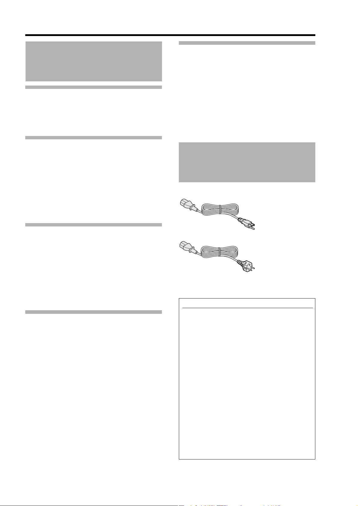
POWER CONNECTION
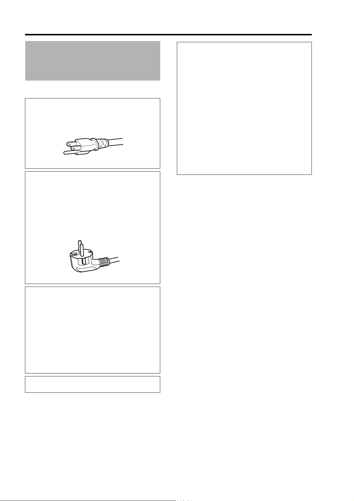
For USA and Canada only
Use only the following power cord.
Power cord
The power supply voltage rating of this product is
AC110V – AC240V. Use only the power cord
designated by our dealer to ensure Safety and
EMC.
Ensure that the power cable used for the projector is
the correct type for the AC outlet in your country.
Consult your product dealer.
IMPORTANT:
The wires in the mains lead on this product are
colored in accordance with the following cord:
Green-and-yellow : Earth
Blue : Neutral
Brown : Live
As these colors may not correspond with the colored
making identifying the terminals in your plug,
proceed as follows:
The wire which is colored green-and-yellow must be
connected to the terminal which is marked M with
the letter E or the safety earth or colored green or
green-and-yellow.
The wire which is colored blue must be connected to
the terminal which is marked with the letter N or
colored black.
The wire which is colored brown must be connected
to the terminal which is marked with the letter L or
colored red.
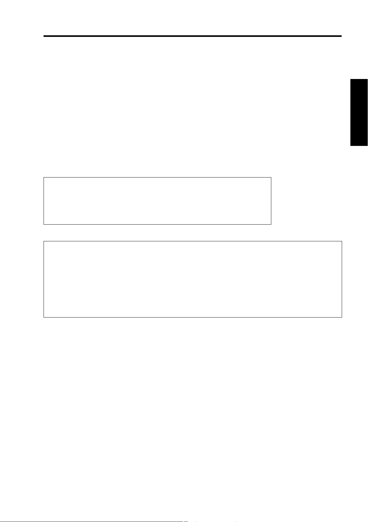
Power cord
For European continent countries
WARNING:
Do not cut off the main plug from this
equipment.
If the plug fitted is not suitable for the power points in
your home or the cable is too short to reach a power
point, then obtain an appropriate safety approved
extension lead or adapter or consult your dealer.
If nonetheless the mains plug is cut off, dispose of
the plug immediately, to avoid a possible shock
hazard by inadvertent connection to the main
supply. If a new main plug has to be fitted, then
follow the instruction given below.
WARNING:
THIS APPARATUS MUST BE EARTHED.
4
Page 5
EMC Supplement
- This equipment is in conformity with the provisions and protection requirements of the corresponding European
Directives.
This equipment is designed for professional projector appliances and can be used in the following environments.
● Controlled EMC environment (for example purpose built broadcasting or recording studio), and the rural outdoors
environment (far away from railways, transmitters, overhead power lines, etc).
In order to keep the best performance and furthermore for electromagnetic compatibility we recommend to use the
cables not exceeding the following length:
Cables Length
Power cord Power supply cord 3.3 m
DVI (X4) Cable Shielded cable 5.0 m
USB Cable Shielded cable 2.0 m
LAN Cable Shielded cable 2.0 m
RS-232C Cable Shielded cable 1.6 m
● The inrush current of this apparatus is 11.945 amperes.
WARNING
This is a Class A product. In a domestic environment this product may cause radio
interference in which case the user may be required to take adequate measures.
In case where the strong electromagnetic waves or magnetism are near the signal
cable, the picture will contain noise. In such cases, please keep the cable away from
the sources of the disturbance.
Dear Customer,
This apparatus is in conformance with the valid European directives and standards regarding electromagnetic
compatibility and electrical safety.
European representative of Victor Company of Japan, Limited is:
JVC Technical Services Europe GmbH
Postfach 10 05 04
61145 Friedberg
Germany
5
Page 6
Getting Started
ENGLISH
Information for Users on Disposal of Old
Equipment
Attention:
This symbol is only
valid in the European
Union.
[European Union]
This symbol indicates that the electrical and electronic
equipment should not be disposed as general household waste
at its end-of-life. Instead, the product should be handed over to
the applicable collection point for the recycling of electrical and
electronic equipment for proper treatment, recovery and
recycling in accordance with your national legislation.
By disposing of this product correctly, you will help to conserve
natural resources and will help prevent potential negative effects
on the environment and human health which could otherwise be
caused by inappropriate waste handling of this product. For more
information about collection point and recycling of this product,
please contact your local municipal office, your household waste
disposal service or the shop where you purchased the product.
Penalties may be applicable for incorrect disposal of this
waste, in accordance with national legislation.
(Business users)
If you wish to dispose of this product, please visit our web
page www.jvc.eu to obtain information about the take-back of
the product.
[Other Countries outside the European Union]
If you wish to dispose of this product, please do so in accordance
with applicable national legislation or other rules in your country
for the treatment of old electrical and electronic equipment.
DEUTSCH
Benutzerinformationen zur Entsorgung alter Geräte
Hinweis:
Dieses Symbol ist nur
in der Europäischen
Uniongültig.
[Europäische Union]
Dieses Symbol zeigt an, dass das elektrische bzw.
elektronische Gerät nicht als normaler Haushaltsabfall entsorgt
werden soll. Stattdessen sollte das Produkt zur fachgerechten
Entsorgung, Weiterverwendung und Wiederverwertung in
Übereinstimmung mit der Landesgesetzgebung einer
entsprechenden Sammelstelle für das Recycling elektrischer
und elektronischer Geräte zugeführt werden.
Die korrekte Entsorgung dieses Produkts dient dem
Umweltschutz und verhindert mögliche Schäden für die
Umwelt und die menschliche Gesundheit, welche durch
unsachgemäße Behandlung des Produkts auftreten können.
Weitere Informationen zu Sammelstellen und dem Recycling
dieses Produkts erhalten Sie bei Ihrer Gemeindeverwaltung,
Ihrem örtlichen Entsorgungsunternehmen oder in dem
Geschäft, in dem Sie das Produkt gekauft haben.
Für die nicht fachgerechte Entsorgung dieses Abfalls können
gemäß der Landesgesetzgebung Strafen ausgesprochen
werden.
(Geschäftskunden)
Wenn Sie dieses Produkt entsorgen möchten, besuchen Sie
bitte unsere Webseite www.jvc.eu, um Informationen zur
Rücknahme des Produkts zu erhalten.
[Andere Länder außerhalb der Europäischen Union]
Wenn Sie dieses Produkt entsorgen möchten, halten Sie sich
dabei bitte an die entsprechenden Landesgesetze und
andere Regelungen in Ihrem Land zur Behandlung
elektrischer und elektronischer Geräte.
ENGLISH
If this symbol is shown, it is only valid in the
European Union.
FRANÇAIS
Informations relatives à l’élimination des
appareils usagés, à l’intention des utilisateurs
Attention:
Ce symbole n’est
reconnu que dans
l’Union européenne.
[Union européenne]
Lorsque ce symbole figure sur un appareil électrique et
électronique, cela signifie qu’il ne doit pas être éliminé en
tant que déchet ménager à la fin de son cycle de vie. Le
produit doit être porté au point de pré-collecte approprié au
recyclage des appareils électriques et électroniques pour y
subir un traitement, une récupération et un recyclage,
conformément à la législation nationale.
En éliminant correctement ce produit, vous contriburez à la
conservation des ressources naturelles et à la prévention
des éventuels effets négatifs sur l’environnement et la santé
humaine, pouvant être dus à la manipulation inappropriée
des déchets de ce produit. Pour plus d’informations sur le
point de pré-collecte et le recyclage de ce produit, contactez
votre mairie, le service d’évacuation des ordures ménagères
ou le magasin dans lequel vous avez acheté le produit.
Des amendes peuvent être infligées en cas d’élimination
incorrecte de ce produit, conformément à la législation
nationale.
(Utilisateurs professionnels)
Si vous souhaitez éliminer ce produit, visitez notre page Web
www.jvc.eu
récupération.
afin d’obtenir des informations sur sa
[Pays ne faisant pas partie de l’Union
européenne]
Si vous souhaitez éliminer ce produit, faites-le conformément
à la législation nationale ou autres règles en vigueur dans
votre pays pour le traitement des appareils électriques et
électroniques usagés.
NEDERLANDS
Informatie voor gebruikers over het
weggooien van oude apparatuur
Let op:
Dit symbool is alleen
geldig in de
Europese Unie.
[Europese Unie]
Deze markering geeft aan dat de elektrische en
elektronische apparatuur bij het einde van de gebruiksduur
niet bij het huishoudelijk afval mag worden gegooid. Het
product moet in plaats daarvan worden ingeleverd bij het
relevante inzamelingspunt voor hergebruik van elektrische
en elektronische apparatuur, voor juiste verwerking,
terugwinning en hergebruik in overeenstemming met uw
nationale wetgeving.
Door dit product naar het inzamelingspunt te brengen, werkt
u mee aan het behoud van natuurlijke hulpbronnen en met
het voorkomen van potentiële negatieve effecten op het
milieu en de volksgezondheid, die anders veroorzaakt
zouden kunnen worden door onjuiste afvalverwerking van dit
product. Neem voor meer informatie over inzamelingspunten
en hergebruik van dit product contact op met de gemeente in
uw woonplaats, het afvalverwerkingsbedrijf of de winkel waar
u het product hebt aangeschaft.
Er kunnen boetes gelden voor een onjuiste verwijdering van
dit afval, in overeenstemming met de nationale wetgeving.
(Zakelijke gebruikers)
Bezoek als u dit product wilt weggooien onze website
www.jvc.eu
product.
voor informatie over het terugnemen van het
[Landen buiten de Europese Unie]
Wanneer u dit product wilt verwijderen, houdt u dan aan de
geldende nationale wetgeving of andere regels in uw land
voor de verwerking van oude elektrische en elektronische
apparatuur.
6
Page 7
ESPAÑOL / CASTELLANO
PORTUGUÊS
Información para los usuarios sobre la
eliminación de equipos usados
Atención:
Este símbolo sólo es
válido en la Unión
Europea.
[Unión Europea]
Este símbolo indica que los aparatos eléctricos y
electrónicos no deben desecharse junto con la basura
doméstica al final de su vida útil. El producto deberá llevarse
al punto de recogida correspondiente para el reciclaje y el
tratamiento adecuado de equipos eléctricos y electrónicos
de conformidad con la legislación nacional.
Si desecha el producto correctamente, estará contribuyendo
a conservar los recursos naturales y a prevenir los posibles
efectos negativos en el medio ambiente y en la salud de las
personas que podría causar el tratamiento inadecuado del
producto desechado. Para obtener más información sobre el
punto de recogida y el reciclaje de este producto, póngase
en contacto con su oficina municipal, su servicio de recogida
de basura doméstica o la tienda en la que haya adquirido el
producto.
De acuerdo con la legislación nacional, podrían aplicarse
multas por la eliminación incorrecta de estos desechos.
(Empresas)
Si desea desechar este producto, visite nuestra página Web
www.jvc.eu para obtener información acerca de la retirada
del producto.
[Otros países no pertenecientes a la Unión
Europea]
Si desea desechar este producto, hágalo de conformidad con la
legislación nacional vigente u otras normativas de su país para
el tratamiento de equipos eléctricos y electrónicos usados.
ITALIANO
Informazioni per gli utenti sullo smaltimento
delle apparecchiature obsolete
Attenzione:
Questo simbolo è
valido solo nell’Unione
Europea.
[Unione Europea]
Questo simbolo indica che l’apparecchiatura elettrica ed
elettronica a cui è relativo non deve essere smaltita tra i rifiuti
domestici generici alla fine della sua vita utile. Il prodotto,
invece, va consegnato a un punto di raccolta appropriato per
il riciclaggio di apparecchiature elettriche ed elettroniche, per
il trattamento, il recupero e il riciclaggio corretti, in conformità
alle proprie normative nazionali.
Mediante lo smaltimento corretto di questo prodotto, si
contribuirà a preservare le risorse naturali e a prevenire
potenziali effetti negativi sull’ambiente e sulla salute umana
che potrebbero essere provocati, altrimenti, da uno
smaltimento inappropriato del prodotto. Per ulteriori
informazioni sul punto di raccolta e il riciclaggio di questo
prodotto, contattare la sede comunale locale, il servizio di
smaltimento rifiuti domestici o il negozio in cui si è acquistato
il prodotto.
L’utente è responsabile del conferimento dell’apparecchio a
fina vita alle appropriate strutture di raccolta, pena le
sanzioni previste dalla vigente legislazione sui rifiuti.
(Per gli utenti aziendali)
Qualora si desideri smaltire questo prodotto, visitare la nostra
pagina web www.jvc.eu per ottenere informazioni sul ritiro del
prodotto.
[Per altre nazioni al di fuori dell’Unione
Europea]
Qualora si desideri smaltire questo prodotto, effettuare lo
smaltimento in conformità alla normativa nazionale
applicabile o alle altre leggi della propria nazione relative al
trattamento delle apparecchiature elettriche ed elettroniche
obsolete.
Informações para os Utilizadores sobre a
Eliminação de Equipamento Antigo
Atenção:
Este símbolo apenas é
válido na União
Europeia.
[União Europeia]
Este símbolo indica que o equipamento eléctrico e
electrónico não deve ser eliminado como um resíduo
doméstico geral, no fim da respectiva vida útil. Pelo contrário,
o produto deve ser entregue num ponto de recolha
apropriado, para efectuar a reciclagem de equipamento
eléctrico e electrónico e aplicar o tratamento, recuperação e
reciclagem adequados, de acordo com a respectiva
legislação nacional.
Ao eliminar este produto da forma correcta, ajudará a
conservar recursos naturais e ajudará a evitar potenciais
efeitos negativos no ambiente e saúde humana, que
poderiam ser causados pelo tratamento residual inadequado
deste produto. Para mais informações sobre o ponto de
recolha e reciclagem deste produto, contacte a respectiva
entidade local, o serviço de eliminação de resíduos ou a loja
onde adquiriu o produto.
Caso estes resíduos não sejam correctamente eliminados,
poderão ser aplicadas penalizações, em conformidade com
a respectiva legislação nacional.
(utilizadores profissionais)
Se pretender eliminar este produto, visite a nossa página da
web em www.jvc.eu para obter informações sobre a
devolução do produto.
[Outros países fora da União Europeia]
Se pretender eliminar este produto, faça-o de acordo com a
legislação nacional aplicável ou outras regras no seu país
para o tratamento de equipamento eléctrico e electrónico
velho.
ΕΛΛΗΝΙΚΑ
Πληροφορίες σχετικά µε την απόρριψη
εξοπλισµού
Προσοχή:
Αυτή η σήµανση ισχύει
µόνο για την
Ευρωπαϊκή Ένωση.
[Ευρωπαϊκή Ένωση]
Αυτή η σήµανση υποδηλώνει ότι ο ηλεκτρικός και
ηλεκτρονικός εξοπλισµός δεν πρέπει να απορριφθεί ως κοινό
οικιακό απόρριµµα. Αντ' αυτού, το προϊόν πρέπει να
παραδοθεί στο ανάλογο σηµείο περισυλλογής για την
ανακύκλωση των ηλεκτρικών και ηλεκτρονικών µερών και
την κατάλληλη επεξεργασία, σύµφωνα µε τη νοµοθεσία
χώρας σας.
Η σωστή απόρριψη αυτού το προϊόντος βοηθάει στη
διαφύλαξη των φυσικών πόρων και στην αποφυγή
αρνητικών επιπτώσεων στο περιβάλλον και στην ανθρώπινη
υγεία, κάτι που ενδέχεται να προκληθεί από την ακατάλληλη
διαχείριση αυτού του προϊόντος ως απόρριµµα. Για
περισσότερες πληροφορίες σχετικά µε τα σηµεία
περισυλλογής
επικοινωνήστε µε τα γραφεία της τοπικής αυτοδιοίκησης, την
υπηρεσία περισυλλογής απορριµµάτων ή το κατάστηµα από
το οποίο αγοράσατε το προϊόν.
Ανάλογα µε τη νοµοθεσία της χώρας σας, ενδέχεται να
επιβληθούν κυρώσεις σε περίπτωση λανθασµένης
απόρριψης αυτού του προϊόντος.
και ανακύκλωσης αυτού του προϊόντος,
της
(Επιχειρήσεις)
Αν επιθυµείτε να απορρίψετε αυτό το προϊόν, επισκεφτείτε το
διαδικτυακό µας τόπο www.jvc.eu για περισσότερες
πληροφορίες σχετικά µε την επιστροφή του προϊόντος.
[Άλλες χώρες εκτός Ευρωπαϊκής Ένωσης]
Αν επιθυµείτε να απορρίψετε αυτό το προϊόν, πρέπει να
τηρήσετε την ισχύουσα εθνική νοµοθεσία ή όποιους άλλους
κανονισµούς για τη χώρα σας για την απόρριψη ηλεκτρικού
και ηλεκτρονικού εξοπλισµού.
7
Page 8
Getting Started
DANSK
Brugerinformation om bortskaffelse af
gammelt udstyr
Bemærk:
Dette symbol er kun
gyldigt i EU.
[EU]
Elektriske produkter og elektroniske apparater med dette
symbol må ikke afhændes på samme måde som almindeligt
husholdningsaffald, når det skal smides ud. I stedet skal
produktet indleveres på det relevante indsamlingssted for
elektriske apparater og elektronisk udstyr, hvor det vil blive
håndteret korrekt og efterfølgende genanvendt og
recirkuleret i henhold til de love, der gælder i dit land.
Ved at bortskaffe dette produkt korrekt, medvirker du til at
bevare naturens ressourcer samt forhindre eventuelle
negative påvirkninger af miljøet og folkesundheden, der
ellers kunne forårsages ved forkert affaldshåndtering af dette
produkt. Mere information om indsamlingssteder og
genanvendelse af dette produkt kan du få ved at kontakte din
lokale kommune, dit renovationsselskab eller den forretning,
hvor du har købt produktet.
Ukorrekt bortskaffelse af dette affald kan være strafbar ifølge
lovgivningen i nogle lande.
(Professionelle brugere)
Hvis du ønsker at bortskaffe dette produkt, kan du på vores
webside www.jvc.eu få information om tilbagetagning af
produktet.
[Lande uden for EU]
Hvis du ønsker at bortskaffe dette produkt, bedes du gøre det
i overensstemmelse med gældende lovgivning eller andre
regler i dit land for behandling af gammelt elektrisk og
elektronisk udstyr.
SVENSKA
Information till användare gällande kassering
av gammal utrustning
Tänk på:
Att denna symbol
endast gäller inom den
Europeiska
gemenskapen.
[Europeiska gemenskapen]
Denna symbol anger att elektrisk och elektronisk utrustning
inte ska kasseras som vanligt hushållsavfall, när de inte ska
användas mer. Istället ska produkten lämnas in på lämplig
återvinningsstation för elektrisk eller elektronisk utrustning,
så att den kan tas om hand och återvinnas i enlighet med ert
lands lagstiftning.
Genom att avyttra denna profukt på rätt sätt, bidrar du till att
bevara naturen och förhindrar potentiellt negativa effekter på
miljön och den mänskiliga hälsan, som annars kan bli
resultatet vid felaktig hantering av denna produkt. Kontakta
ditt kommunkontor, det företag som hanterar dina
hushållssopor eller butiken där du köpt produkten, för mer
information om återvinningscentraler.
Det kan hända att du bötfälls i enlighet med ert lands
lagstiftning om detta avfall kasseras på fel sätt.
(Företagsanvändare)
Om ni vill kassera denna produkt, besök vår webbsida
www.jvc.eu
produkten.
för att få information om returnering av
[Övriga länder utanför den Europeiska
gemenskapen]
Om du vill kassera denna produkt, ska detta göras i enlighet
med gällande lagstiftning i landet, eller enligt andra
bestämmelser i ditt land, för behandling av gammal elektrisk
eller elektronisk utrustning.
SUOMI
Tietoja käyttäjille vanhojen laitteiden
hävittämisestä
Huomio:
Tämä symboli on
voimassa vain
Euroopan unionissa.
[Euroopan unioni]
Tämä symboli tarkoittaa, että sähkö- ja elektroniikkalaitteita
ei tule laittaa talousjätteisiin, kun ne poistetaan käytöstä. Sen
sijaan tuotteet tulee toimittaa asianmukaiseen sähkö- ja
elektroniikkalaitteiden kierrätyspisteeseen, jossa ne
käsitellään uusiokäyttöä ja kierrätystä varten paikallisen
lainsäädännön mukaan.
Kun hävität tuotteen asianmukaisella tavalla, autat
säästämään luonnonvaroja ja estämään mahdollisia
ympäristö- ja terveyshaittoja, joita voisi aiheutua tämän
tuotteen vääränlaisesta hävittämisestä. Lisätietoja
keräyspisteistä ja tämän tuotteen kierrätyksestä saat
paikkakuntasi viranomaisilta, kotitalousjätteiden keräyksestä
huolehtivasta yrityksestä tai liikkeestä, josta ostit tuotteen.
Tuotteen vääränlaisesta hävittämisestä voi seurata
paikallisen lainsäädännön mukaisia rangaistuksia.
(Yrityskäyttäjät)
Jos haluat hävittää tämän tuotteen, web-sivustoltamme
osoitteessa www.jvc.eu löydät tietoja käytetyn tuotteen
palautuksesta.
[Muut maat Euroopan unionin ulkopuolella]
Jos haluat hävittää tämän tuotteen, tee se kansallisen
lainsäädännön tai muiden maassasi voimassa olevien
määräysten mukaan, jotka koskevat vanhojen sähkö- ja
elektroniikkalaitteiden käsittelyä.
NORSK
Informasjon til brukerne om kassering av
gammelt utstyr
OBS!
Dette symbolet er kun
gyldig i den Europeiske
Union og i EFTA-landene
Norge, Island og Sveits.
[Europeiske Union]
Dette symbolet betyr at det elektriske eller elektroniske
utstyret ikke skal kasseres som vanlig husholdningsavfall når
det har nådd slutten av sin levetid. I stedet skal produktet
leveres til en passende mottaksstasjon for kasserte
elektriske og elektroniske produkter, slik at disse kan
behandles, gjenvinnes og resirkuleres i samsvar med
nasjonal lovgivning.
Hvis du kasserer dette produktet på riktig måte, bidrar til du til
å bevare naturlige ressurser og til å motvirke de negative
virkningene på miljøet og den menneskelige helse som kan
oppstå hvis produktet kasseres på feil måte. Hvis du vil ha
mer informasjon om mottaksstasjoner og gjennvinning av
dette produktet, kan du ta kontakt med kommunen din,
renovasjosselskapet ditt eller den forhandleren du kjøpte
produktet av.
Feilaktig kassering av dette utstyret kan kanskje bøtelegges,
avhengig av nasjonale lover og regler.
(Bedriftsbrukere)
Hvis du ønsker å kassere dette produktet, kan du gå til
hjemmesiden vår på www.jvc.eu eller www.elretur.no for å få
informasjon om retur av dette produktet.
[Andre land utenfor EU]
Hvis du ønsker å kassere dette produktet, må du gjøre det i
samsvar med gjeldende nasjonal lovgivning eller andre
regler som gjelder i landet ditt når det gjelder behandling av
gammelt elektrisk og elektronisk utstyr.
8
Page 9
РУССКИЙ
Информация для пользователей,
выбрасывающих старое оборудование
Внимание:
Действие этого символа
распространяется
только на Европейский
Союз.
ČESKY
Informace pro uživatele k likvidaci starého
zařízení
Upozornění:
Te n to sy mb o l j e pl at ný
jen v Evropské unii.
[Европейский Союз]
Это символ указывает, что после окончания срока службы
соответствующего электрического или электронного
оборудования, нельзя выбрасывать его вместе с обычным
бытовым мусором. Вместо этого, оно подлежит сдаче на
утилизацию в соответствующий пункт приема
электрического и электронного оборудования для
последующей переработки и утилизации в соответствии с
национальным законодательством.
Обеспечивая правильную утилизацию данного продукта,
Вы помогаете сберечь природные ресурсы и
предотвращаете ущерб для окружающей среды и
здоровья людей, который возможен в случае
ненадлежащего обращения. Более подробную
информацию о пунктах приема и утилизации данного
продукта можно получить в местных муниципальных
органах, на предприятии по вывозу бытового мусора или
по месту приобретения продукта.
Нарушение правил утилизации данного типа отходов в
соответствии с национальным законодательством
является административным правонарушением.
(Организации-пользователи)
Прежде чем выбрасывать данный продукт, ознакомьтесь
с информацией о приемке отработавших продуктов,
приведенной на веб-узле www.jvc.eu.
[Страны, не входящие в Европейский Союз]
Если Вы собираетесь выбросить данный продукт,
руководствуйтесь национальным законодательством или
другими правилами, действующими в Вашей стране по
отношению к переработке старого электрического и
электронного оборудования.
POLSKI
Informacja dla użytkowników, dotycząca
utylizacji niesprawnych urządzeń
Uwaga:
Taki symbol jest ważny
tylko w Unii Europejskej.
[Kraje Unii Europejskiej]
Symbol przedstawiony obok oznacza, że urządzeń
elektrycznych i elektronicznych po zakończeniu okresu ich
eksploatacji nie należy wyrzucać razem z odpadami
gospodarczymi. Należy je natomiast przekazać do punktu
odbioru urządzeń elektrycznych i elektronicznych w celu ich
odpowiedniego przerobu, odzysku i utylizacji zgodnie z
krajowym ustawodawstwem.
Dbając o prawidłową utylizację produktu, przyczyniasz się do
ochrony zasobów naturalnych i zmniejszasz negatywny wpływ
oddziaływania na środowisko i zdrowie ludzi, zagrożone
niewłaściwym traktowaniem odpadów elektronicznych.
Szczegółowe informacje dotyczące punktów zbiórki i
powtórnego przerobu odpadów można uzyskać u władz
lokalnych, w firmach zajmujących się zagospodarowaniem
odpadów lub w sklepie z artykułami elektronicznymi.
Zgodnie z krajowym ustawodawstwem w przypadku
nieprawidłowego usuwania wspomnianych odpadów mogą
być nakładane kary.
(Użytkownicy biznesowi)
Jeśli zaszła potrzeba pozbycia się niniejszego produktu,
prosimy zajrzeć na strony www.jvc.eu
informacje o możliwości jego odbioru.
, aby uzyskać
[Kraje poza Unią Europejską]
W razie konieczności pozbycia się niniejszego produktu
prosimy postępować zgodnie z lokalnymi przepisami lub
innymi zasadami postępowania ze zużytym sprzętem
elektrycznymi i elektronicznymi.
[Evropská unie]
Tento symbol udává, že elektrické a elektronické vybavení
nesmí být po skončení životnosti likvidován jako běžný
komunální odpad. Produkt musí být předán na příslušném
sběrném místě k správnému zpracování, regeneraci a
recyklaci elektrického a elektronického vybavení. Musí být
zlikvidován správně v souladu s národními předpisy vaší
země.
Správnou likvidací tohoto produktu pomůžete zachovat
přírodní zdroje a napomáháte prevenci potenciálních
negativních dopadů na životní prostředí a lidské zdraví, což
by mohly být důsledky nesprávné likvidace tohoto produktu.
Podrobnější informace o sběrném místě a recyklaci tohoto
produktu si vyžádejte od místních úřadů, podniku
zabývajícího se likvidací komunálních odpadů ve vašem místě
nebo obchodu, kde jste produkt zakoupili.
Nesprávná likvidace tohoto odpadu může mít za následek
postih podle národní legislativy.
(Firemní uživatelé)
Přejete-li si tento produkt zlikvidovat, navštivte prosím naši
webovou stránku www.jvc.eu
možnosti vrácení produktu.
, kde získáte informace o
[Ostatní země mimo Evropskou unii]
Přejete-li si zlikvidovat tento produkt, proveďte to prosím v
souladu s příslušnými národními zákony nebo jinými předpisy
platnými ve vaší zemi, které se vztahují k likvidaci starého
elektrického a elektronického vybavení.
MAGYAR
Felhasználói tájékoztató az elhasznált
berendezések ártalmatlanításáról
Figyelem!
Ez a szimbólum csak az
Európai Unióban
érvényes.
[Európai Unió]
Ez a szimbólum azt jelzi, hogy az elektromos és elektronikus
berendezést a hasznos élettartama végén nem szabad
háztartási szemétként kezelni. Ehelyett a terméket a
megfelelő, elektromos és elektronikus berendezések
hulladékainak hasznosítására szakosodott gyűjtőhelyre kell
vinni, hogy a nemzeti törvényeknek megfelelően történjék
kezelése, visszanyerése és újrahasznosítása.
A termék megfelelő ártalmatlanításával segít megőrizni a
természetes erőforrásokat és megelőzheti azokat a
környezetre és az egészségre gyakorolt ártalmas hatásokat,
amelyeket a termék hulladékának helytelen kezelése
egyébként okozhat, továbbá csökkenti az elektromos
berendezésekből származó hulladékok mennyiségét és segíti
az újrahasznosítást és újrafeldolgozást.
A nemzeti törvények értelmében az ilyen hulladék helytelen
ártalmatlanítása esetén büntetést szabhatnak ki.
(Üzleti felhasználók)
Amennyiben ártalmatlanítani kívánja ezt a terméket, kérjük,
látogasson el weboldalunkra: www.jvc.eu, ahol tájékoztatást
kaphat a termék visszavételével kapcsolatban.
[Az Európai Unión kívüli országok]
Amennyiben ártalmatlanítani kívánja ezt a terméket, kérjük, a
megfelelő nemzeti jogszabályok, illetve az Ön országának az
elektromos és elektronikus berendezések hulladékának
kezelésére vonatkozó, egyéb szabályai szerint végezze.
9
Page 10
Getting Started
Contents
Getting Started
Safety Precautions . . . . . . . . . . . . . . . . . . . . . . . . . . . 2
Contents . . . . . . . . . . . . . . . . . . . . . . . . . . . . . . . . . . 10
Accessories . . . . . . . . . . . . . . . . . . . . . . . . . . . . . . . . 10
Precautions During Use . . . . . . . . . . . . . . . . . . . . . . 11
Names and Functions of Parts . . . . . . . . . . . . . . . . . 12
Connection and Installation
Installation . . . . . . . . . . . . . . . . . . . . . . . . . . . . . . . . . 14
Optional Projection Lens . . . . . . . . . . . . . . . . . . . . 14
Minimum Space Required . . . . . . . . . . . . . . . . . . . 14
Projector Installation Angle . . . . . . . . . . . . . . . . . . 15
Installing the Projector and Screen . . . . . . . . . . . . . . 15
Screen Size and Projection Distance . . . . . . . . . . 18
Connecting Video Signals of the Computer . . . . . . . 20
Connection During Single-Screen
Mode Display . . . . . . . . . . . . . . . . . . . . . . . . . . . . . 20
Connection During Two-Screen/Four-Screen
Mode Display . . . . . . . . . . . . . . . . . . . . . . . . . . . . . 22
Others
Troubleshooting . . . . . . . . . . . . . . . . . . . . . . . . . . . . 51
What to do when these messages are displayed . . . 53
Warnings Using Indicators . . . . . . . . . . . . . . . . . . . . 54
Warning Status . . . . . . . . . . . . . . . . . . . . . . . . . . . . . 55
RS-232C Interface . . . . . . . . . . . . . . . . . . . . . . . . . . 56
Communication Specifications . . . . . . . . . . . . . . . . 56
Command Format . . . . . . . . . . . . . . . . . . . . . . . . . 56
Maintenance . . . . . . . . . . . . . . . . . . . . . . . . . . . . . . . 58
Cleaning and Replacing the Filter . . . . . . . . . . . . . 58
Routine Servicing . . . . . . . . . . . . . . . . . . . . . . . . . . 59
Replacement of Light Source Lamp . . . . . . . . . . . 59
Specifications . . . . . . . . . . . . . . . . . . . . . . . . . . . . . . 60
Dimensional Outline Drawing . . . . . . . . . . . . . . . . 62
Accessories
● Power Cord
For the US market (3.3 m x 1)
Network Settings
Connection Using a LAN Cable . . . . . . . . . . . . . . . . 24
Connection Example . . . . . . . . . . . . . . . . . . . . . . . 24
Specifications of PC for Controlling this
Projector . . . . . . . . . . . . . . . . . . . . . . . . . . . . . . . . 24
Turning On the Main Power . . . . . . . . . . . . . . . . . . . 25
IP Address Settings . . . . . . . . . . . . . . . . . . . . . . . . . . 26
Assigning a static IP address . . . . . . . . . . . . . . . . . 26
Assigning IP Address from the DHCP Server . . . . 29
Using the Mail Delivery Feature . . . . . . . . . . . . . . . . 29
Connection Example (When DHCP Server is
Used) . . . . . . . . . . . . . . . . . . . . . . . . . . . . . . . . . . . 29
Operation and Settings
Projecting Image . . . . . . . . . . . . . . . . . . . . . . . . . . . . 30
Useful Features During Projection . . . . . . . . . . . . . 31
Displaying the Menu . . . . . . . . . . . . . . . . . . . . . . . . . 32
User Settings Menu . . . . . . . . . . . . . . . . . . . . . . . . . . 33
User Settings Menu Structure . . . . . . . . . . . . . . . . 33
(1) Main Menu . . . . . . . . . . . . . . . . . . . . . . . . . . . . 34
(2) Image Menu . . . . . . . . . . . . . . . . . . . . . . . . . . . 37
(3) Setting Menu . . . . . . . . . . . . . . . . . . . . . . . . . . 38
(4) Convergence Menu . . . . . . . . . . . . . . . . . . . . . 39
(5) Lens Menu . . . . . . . . . . . . . . . . . . . . . . . . . . . . 40
(6) Option Menu . . . . . . . . . . . . . . . . . . . . . . . . . . . 41
Administrator Settings Menu . . . . . . . . . . . . . . . . . . . 43
Administrator Settings Menu Structure . . . . . . . . . 43
(7) Admin. Network Menu . . . . . . . . . . . . . . . . . . . 44
(8) Admin. E-mail Menu . . . . . . . . . . . . . . . . . . . . . 46
(9) Admin. Option Menu . . . . . . . . . . . . . . . . . . . . . 48
(10) Admin. Signal Menu . . . . . . . . . . . . . . . . . . . . 49
For the EU market (3.3 m x 1)
● Plug Holder x1
● Other items include the instruction manual, warranty,
and other printed materials.
How to Read this Manual
Symbols used in this manual
CAUTION: Describes precautions to note when
operating this product.
NOTE : Describes reference information, such as
functions and restrictions during use.
A
: Indicates the page or section to refer to.
Content of this manual
● Personal computers or computers are expressed as
computers or PCs in this manual.
● Contents of this manual are the copyright of JVC. All
rights reserved. Unauthorized reproduction and
duplication of this manual, in whole or in part,
without the permission of JVC is strictly prohibited.
●
The names of other companies’ products that appear
in this manual are the trademark or registered
trademark of the respective companies. Symbols
such as
● Designs, specifications, and other details described
in this manual may be modified for improvement
without prior notice.
™,
, and are omitted in this manual.
10
Page 11

Precautions During Use
Burning-in of D-ILA Device
oDo not allow the same still picture to be
projected for a long time or an abnormally
bright video image to be projected
Do not project still images with a high brightness or
high contrast on the screen for a long time. This video
image could be burnt into the D-ILA device.
Pay special attention when projecting video games and
computer program images.
Motion images such as normal video playback images
do not pose the burning-in problem.
Viewing Conditions (Brightness
of Room)
oBrightness of the room
Avoid direct exposure of screen to direct sunlight and
lights such as by using a curtain. Images can be well
projected by darkening the brightness of the room.
oDo not view screen for prolonged hours
Looking at the screen continually for a prolonged time
is tiring to the eyes. Allow your eyes to rest at intervals.
oDo not use this unit when image flickers
Image may flicker due to installation conditions and
environment. This may cause your eyesight to
deteriorate.
Maintenance Procedures
oClean dirt on the cabinet
Do this with a soft cloth. In case of heavy soiling, soak
a cloth in neutral detergent diluted with water, wring dry
and wipe, followed by wiping again using a dry cloth.
oPay attention to the following to prevent the
cabinet from deteriorating in condition,
getting damaged, or the paint from coming
off.
● Do not wipe with a stiff cloth
● Do not wipe with force
● Do not wipe with thinner or benzene
● Do not spray volatile chemicals like insecticide
● Do not allow prolonged contact with rubber or plastic
products
oClean dirt on the lens
Do this using commercial blowers or lens cleaning
papers (for cleaning glasses and cameras).
Do not use fluid-type cleaning agents. This may lead to
peeling of the surface coating film.
Lens surface is fragile. Avoid rubbing it hard or
knocking it.
Environment of Use
oDo not use this projector in rooms with
cigarette smoke or oily smoke
Do not use this projector in rooms with cigarette smoke
or oily smoke. This may cause the unit to malfunction.
oWhen mounting this projector to the ceiling
Check the temperature around the projector unit.
When a heater is in use, the ceiling may reach a
temperature higher than anticipated, hence leading to
malfunction of the unit.
Gauging replacement time of components
This product comes with replacement components required for maintaining the functions of this product, such as
optical components, cooling fan and filters. The timing for replacing components varies considerably according
to the frequency and environment of use. For details on replacement of components (except filters), please
consult your authorized dealer.
11
Page 12
Getting Started
F
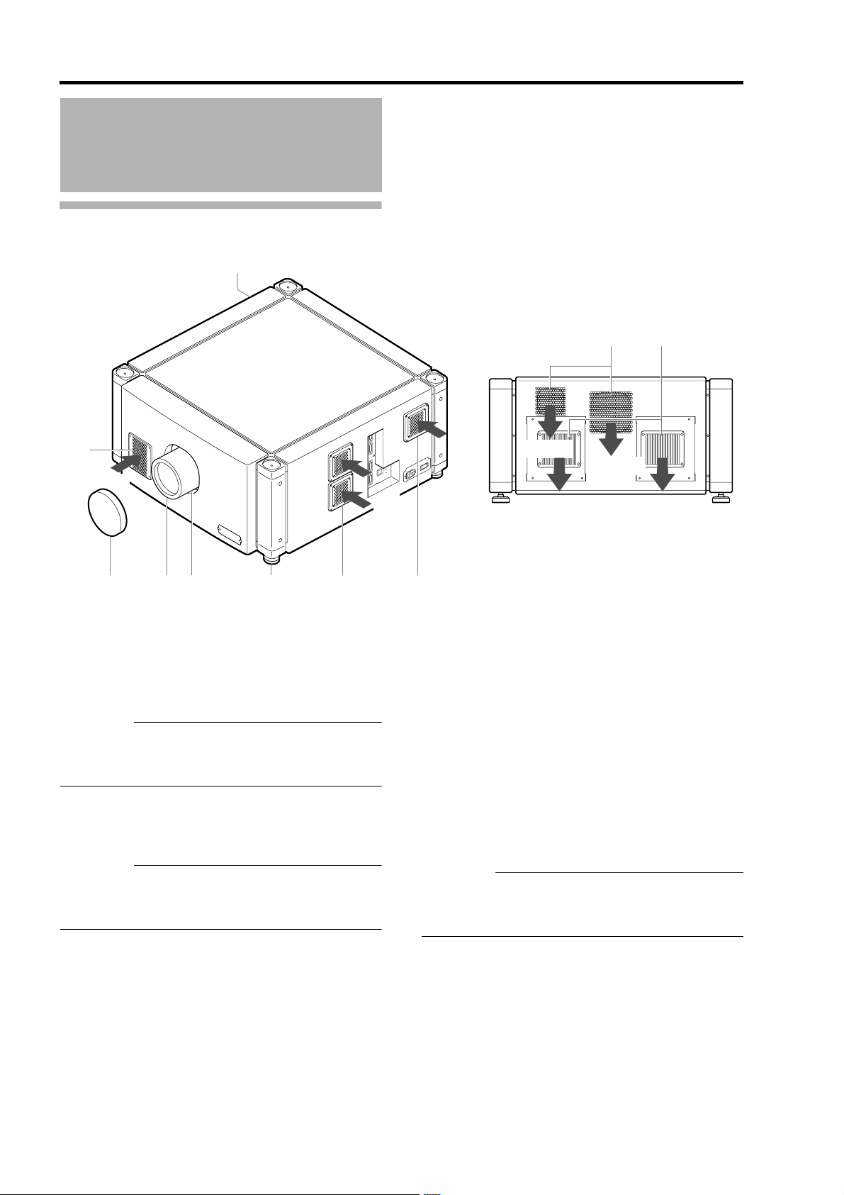
Names and Functions of Parts
Front/Right/Rear Side
A
Intake air
L
O
R
T
N
O
C
Intake
air
Intake
air
G H
Exhaust air
Exhaust air
B
C D E F
A Air Inlet/Filter
The air inlets absorb air to cool the interior of the
projector. A filter is mounted inside the projector to
remove dirt in the air that enters through the inlets. Clean
the filter regularly. (A Page 58)
CAUTION:
● Do not block the air inlets with papers, cloth, or soft
cushions. Doing so may cause heat to trap inside the
projector and result in fire or malfunction.
B Lens Cap (included with the optional lens)
Fit the cap on the lens when this projector is not in use to
prevent the lens from becoming dirty.
CAUTION:
● Do not project images with the lens cap attached. The
lens cap may be deformed due to the heat, or the
projector may malfunction.
C Projection Lens (optional)
Zoom lens or short focal length lens is optional.
(A Page 60)
Remove the lens cap before projection.
F
D Lens Mounting Bracket
Mount the optional projection lens.
E Adjustable Feet (x4)
Adjust the feet until the projector is level. The adjustable
range is 20 mm for each. (A Page 15)
F Air Inlet/Filter (Right Side: x3, Left Side: x1)
The air inlets absorb air to cool the interior of the
projector. A filter is mounted inside the projector to
remove dirt in the air that enters through the inlets. Clean
the filter regularly. (A Page 58)
G Vent Hole
Warm air exits from the hole after cooling the projector.
CAUTION:
● Do not block the vent holes with papers, cloth, or soft
cushions. Doing so may cause heat to trap inside the
projector and result in fire or malfunction.
H Vent Hole
Warm air exits from the hole after cooling the lamp.
12
Page 13
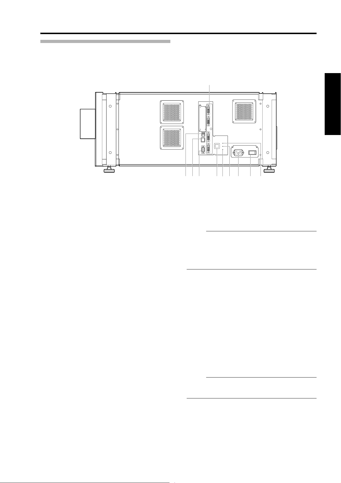
Right Side
I
RO
J K LNM P Q
DVI 1
DVI 2
CONTROL
USB
DVI 3
LAN
RS-232C
STANDBY/ON
OPERATE I/B
LAMP
DVI 4
WARNING
I [DVI 1 to 4] Terminal
This is an input terminal for video signals. Connect it to
the video output terminal of the computer.
(A Page 21, 23)
J [USB] Terminal
Enables control of this projector by connecting it to a
computer.
K [LAN] Terminal
Enables control of this projector using a computer that is
connected to the network.
L [RS-232C] Terminal
This is the RS-232C interface-specific terminal. This
projector can be controlled by connecting it to a computer
using a RS-232C cable.
M [OPERATE I/B] Button
Pressing this button for one second or longer when in the
standby mode (main power supply is ON) turns on the
power of the projector unit. Pressing it for one second or
longer when the power is ON switches the projector to
the standby mode.
N [WARNING] Indicator
This indicator lights up in red when abnormality occurs on
this projector. For details, refer to AWarnings Using
IndicatorsB. (A Page 54)
O [LAMP] Indicator
This indicator lights up in yellow when the lamp time
exceeds 1900 hours.
NOTE:
● For details on indicator displays during warnings, refer
to AWarnings Using IndicatorsB. (A Page 54)
● A lamp life message appears when the lamp time has
exceeded 2000 hours.
(A Page 53)
P AC Power Input Terminal
Connect the supplied cord to this terminal.
Q Main Power Supply Switch
Use this to turn ON/OFF the main power supply of the
projector unit.
R [STANDBY/ON] Indicator
Lit (Red) : When in the standby mode.
Lit (Green) : When power is supplied.
Blinking (Red) : When cooling down (cool down mode).
(A Page 31)
Blinking (Green) : When the projected image is
temporarily hidden. (A Page 31)
NOTE:
● For details on indicator displays during warnings, refer
to AWarnings Using IndicatorsB. (A Page 54)
13
Page 14
Connection and Installation
Installation
Please read the following carefully when installing this unit.
Optional Projection Lens
Mount the optional projection lens (A Page 60). For details on mounting the lens, please consult your authorized dealer.
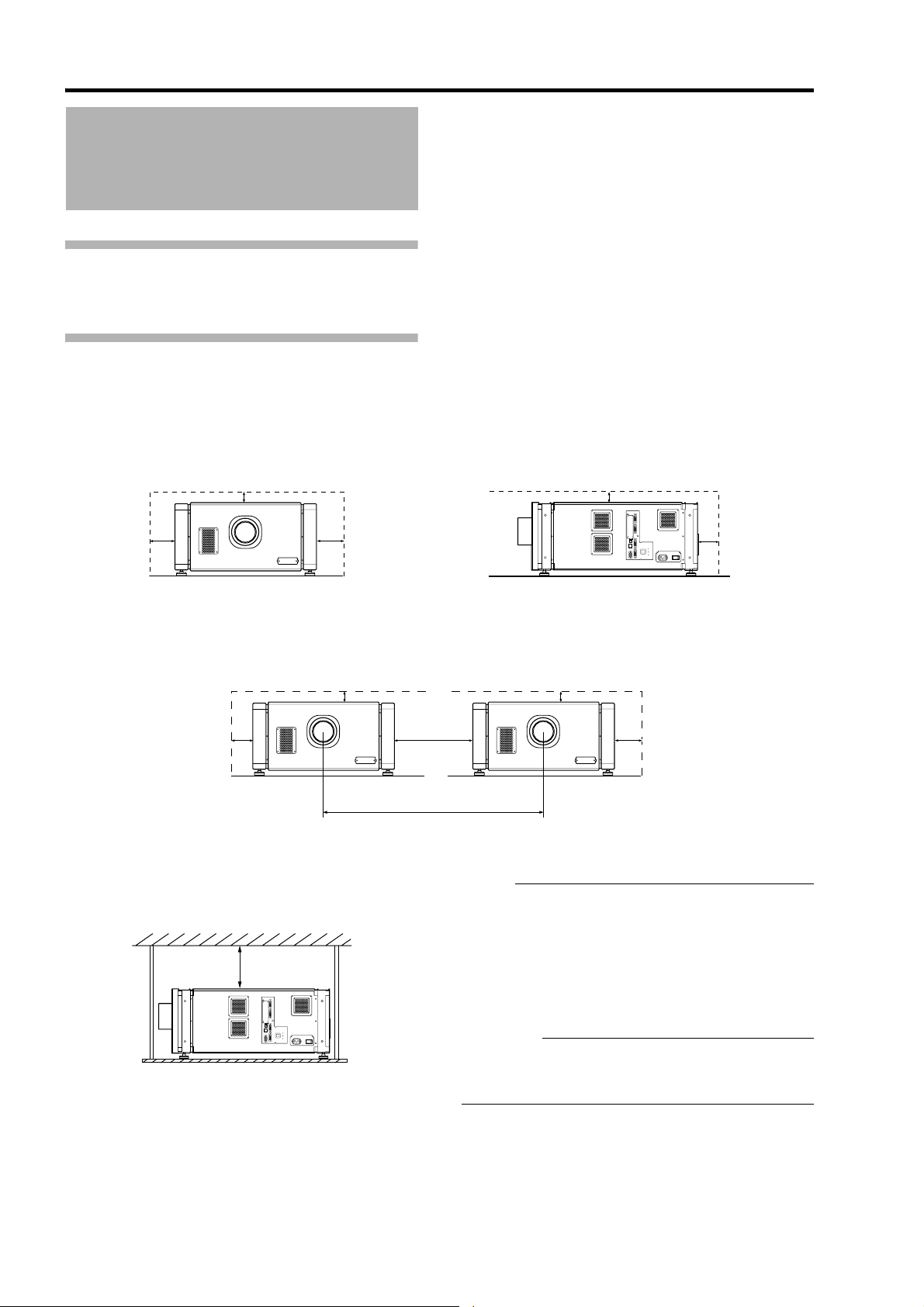
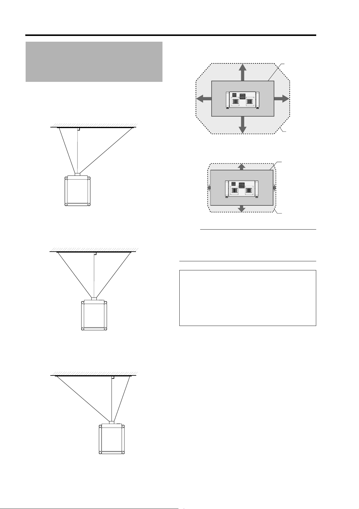
Minimum Space Required
Do not use a cover that may enclose this unit or block the air inlets/vent holes. Allow sufficient space around this unit.
When this unit is enclosed in a space with dimensions as indicated below, ventilate accordingly so that the internal and
external temperatures are the same.
When using one set of projector
300 mm
600 mm600 mm
When using two sets of projectors side by side
300 mm
600 mm
640 mm
When the projector is suspended
600 mm and
above
DVI 1
DVI 2
CONTROL
USB
DVI 3
LAN
STANDBY/ON
OPERATE I/B
LAMP
DVI 4
WARNING
RS-232C
300 mm
DVI 1
DVI 2
CONTROL
USB
DVI 3
LAN
STANDBY/ON
OPERATE I/B
LAMP
DVI 4
WARNING
RS-232C
600 mm
300 mm
600 mm
1,300 mm
NOTE:
● To prevent the projector from falling or toppling, it is
recommended that the holder be fastened to the unit
using bolts.
● To mount the projector to the ceiling, mount a special
shelf to the ceiling, followed by installing the unit on
the shelf. For safety and maintenance purposes,
equipment that eases adjustment to a suitable height
for maintenance is required.
CAUTION:
● Special expertise and techniques are required for
mounting this unit. Be sure to ask your dealer or a
specialist to perform mounting.
14
Page 15
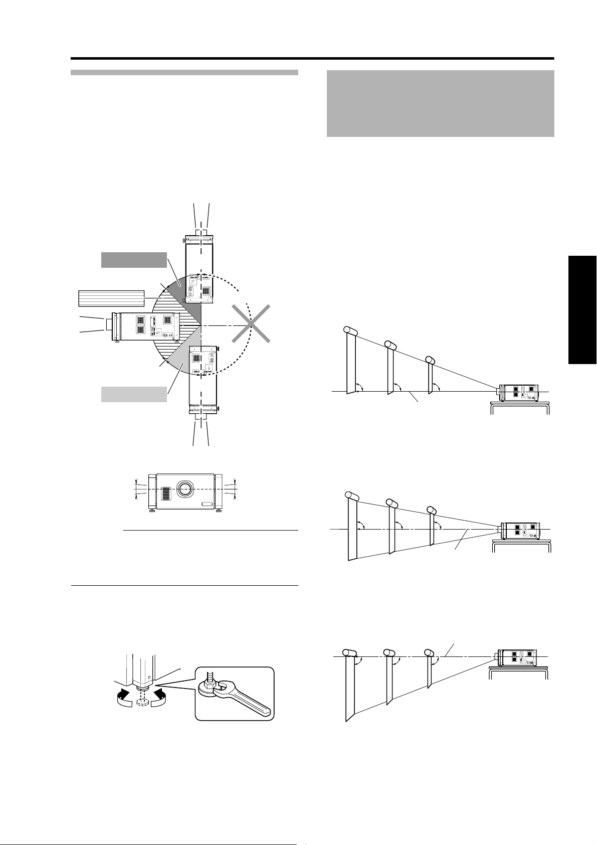
Projector Installation Angle
Installing the Projector
You can install this projector between 90.
Images will be properly displayed if the horizontal angle
is between the range of 5.
However, you have to configure using [Installation
Style](A Page 48) for certain installation orientations.
A: Upward installation (+45 to +90)
B: Horizontal installation (-45 to +45)
C: Downward installation (-45 to -90)
A: +45 to +90
B: -45 to +45
C: -45 to -90
+45
USB
LAN
RS-232C
-45
DVI 1
DVI 2
CONTROL
DVI 3
STANDBY/ON
OPERATE I/B
LAMP
DVI 4
WARNING
+90
RS-232C
LAN
USB
DV
DV
I 3
I 4DVI 1DVI 2
OPERA
TE I/
B
STANDBY/ON
WA
LAMP
RNING
-90
CONTR
OL
T Not applicable
ING
RN
LAMP
WA
STANDBY/ON
B
TE I/
OPERA
I 3
I 4DVI 1DVI 2
DV
DV
OL
CONTR
USB
LAN
RS-232C
and Screen
It is recommended that this projector be installed at right
angle to the screen.
When a zoom lens (optional) is in use, you can make use
of the lens shift feature of this projector to shift the
projection screen vertically between 0% to 50%, and
horizontally between 0% to 25%.
When a short focal length lens (optional) is in use, you
can shift the projection screen position vertically between
0% to 15%, and horizontally between 0% to 5%.
Below are some examples on the layout when a zoom
lens is used.
When shift amount in the upward direction is
+50 %
Install the projector such that the lower end of the
projection screen is at the same height as the center of
the lens.
Screen
90 90 90
Center Line of Lens
55
CAUTION:
● To ceiling-mount this unit, special expertise and skills
are necessary. Make to sure request the authorized
dealer or specialized work contractors for installation.
● The projector cannot be installed upside down.
Adjusting the Inclination
Adjust the horizontal angle of the projector.
Lift the projector and turn the nut of the adjustable foot
with a spanner in the direction indicated by the arrow to
extend or retract the foot. The adjustable range is 20 mm.
Extend Retract
When shift amount in the upward/downward
direction is 0 %
Install the projector such that the center of the projection
screen is at the same height as the center of the lens.
Screen
90 90 90
Center Line of Lens
When shift amount in the downward direction
is -50 %
Install the projector such that the upper end of the
projection screen is at the same height as the center of
the lens.
Screen
90 90 90
Center Line of Lens
15
Page 16
Connection and Installation
Installing the Projector
Movable Range of Projected Image
GL-MS4015SZG Zoom lens
and Screen (Cont’d)
When shift amount in the right direction is
+25 %
Install the projector such that the center of the lens is
aligned with the 1/4 position from the left edge of the
screen.
When shift amount in the left/right direction
is 0 %
Install the projector such that the center of the lens is
aligned with the center of the screen.
Projected
50 %
25 %
50 %
Image
25 %
Movable
Range
GL-MS4011SG Short focal length lens
15 %
5 %
15 %
Projected
Image
5 %
Movable
Range
NOTE:
● When using the lens shift feature, do not exceed the
range (shift amount) as shown above. If the shift
amount exceeds the range as shown, shadows will
appear on the projected image.
When shift amount in the left direction is -25 %
Install the projector such that the center of the lens is
aligned with the 1/4 position from the right edge of the
screen.
Lens Fixation Mechanism
A screw for securing the lens mechanism is attached in
the factory shipment to prevent damage of the
equipment during transportation. If the lens does not
move horizontally or vertically when you operate
AShiftB in the Lens menu, this could be because the
screw has not been removed. When this occurs,
please consult your authorized dealer.
16
Page 17
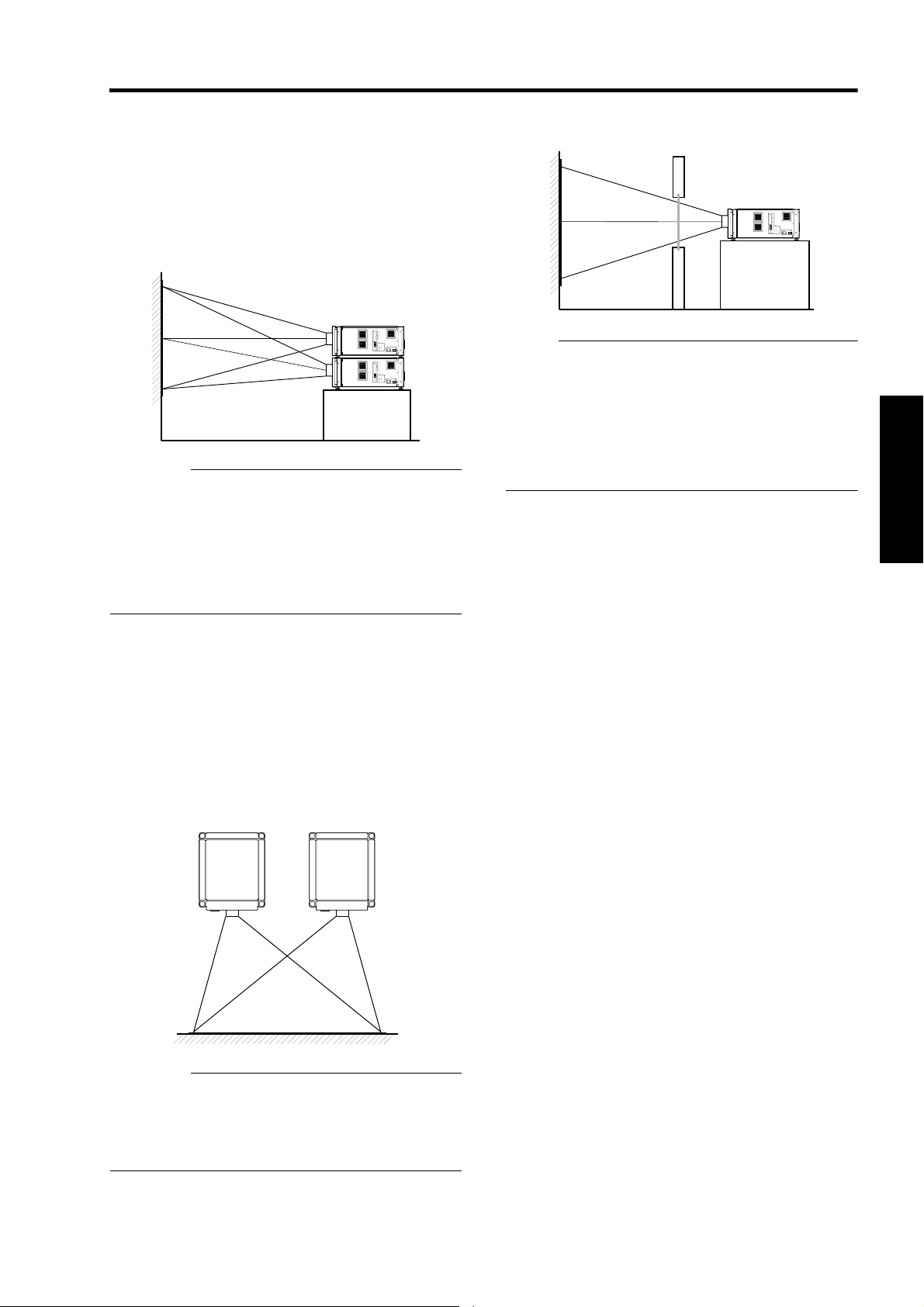
Overlaying projected images (when zoom
lens is in use)
Projecting images by stacking projectors
The lens shift feature enables you to use up to three
stacked projectors at the same time.
Stacking the projectors enhances the brightness level,
and helps to project images that are sufficiently bright
even when the venue is relatively big or bright.
CAUTION:
● When the projectors are stacked together during use,
ensure that the installation site is sufficiently strong
and there is proper air cooling around the projectors.
Take the necessary measures to prevent the
projectors from toppling or falling off so as to ensure
safety during emergency situations, such as
earthquakes, and to prevent accidents from occurring.
For details, please consult your authorized dealer.
When light passes through the glass of
projection booth
NOTE:
● When light passes through the glass, the quantity of
light decreases. Make sure that the glass of the
projection booth is not more than one piece.
● Do not use glass if possible.
● When projecting light on an inclined glass surface,
adjust the glass angle as well as installation angle of
this unit accordingly to prevent impact on the image
due to diffuse reflection.
Projecting images by arranging projectors
side by side
The lens shift feature enables you to use up to two
projectors that are arranged side by side.
Arranging two projectors side by side enhances the
brightness level, and helps to project images that are
sufficiently bright even when the venue is relatively big or
bright.
When projecting images by arranging the projectors side
by side, adjust the shift amount of both projectors
accordingly to superimpose the images.
CAUTION:
● When using the projectors by arranging them side by
side, ensure that the installation site is sufficiently
strong and there is proper air cooling around the
projectors. For details, please consult your authorized
dealer.
17
Page 18
Connection and Installation
Installing the Projector
and Screen (Cont’d)
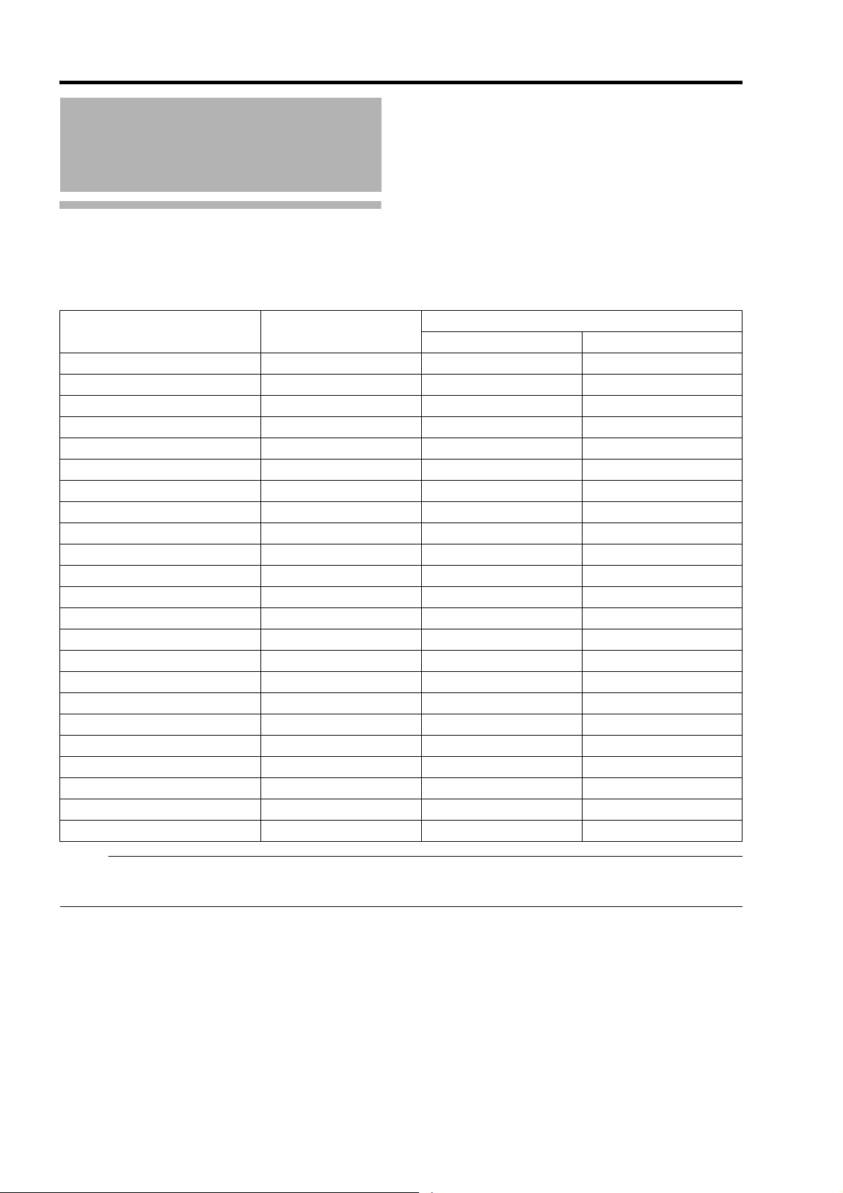
Screen Size and Projection Distance
Adjust the distance from the lens to the screen to achieve your desired screen size.
GL-MS4015SZG Zoom lens
Projection Screen Size
(Diagonal Length)
80" (Approx. 2.03 m) 1.75 m 3.19 m 2.58 m
90" (Approx. 2.29 m) 1.97 m 3.60 m 2.91 m
100" (Approx. 2.54 m) 2.19 m 4.01 m 3.25 m
110" (Approx. 2.79 m) 2.41 m 4.42 m 3.58 m
120" (Approx. 3.05 m) 2.63 m 4.83 m 3.91 m
130" (Approx. 3.30 m) 2.85 m 5.24 m 4.25 m
140" (Approx. 3.56 m) 3.07 m 5.65 m 4.58 m
150" (Approx. 3.81 m) 3.29 m 6.06 m 4.91 m
160" (Approx. 4.06 m) 3.51 m 6.46 m 5.25 m
170" (Approx. 4.32 m) 3.73 m 6.87 m 5.58 m
180" (Approx. 4.57 m) 3.94 m 7.28 m 5.91 m
190" (Approx. 4.83 m) 4.16 m 7.69 m 6.24 m
200" (Approx. 5.08 m) 4.38 m 8.10 m 6.58 m
210" (Approx. 5.33 m) 4.60 m 8.51 m 6.91 m
220" (Approx. 5.59 m) 4.82 m 8.92 m 7.24 m
230" (Approx. 5.84 m) 5.04 m 9.33 m 7.58 m
240" (Approx. 6.10 m) 5.26 m 9.74 m 7.91 m
250" (Approx. 6.35 m) 5.48 m 10.15 m 8.24 m
260" (Approx. 6.60 m) 5.70 m 10.55 m 8.58 m
270" (Approx. 6.86 m) 5.92 m 10.96 m 8.91 m
280" (Approx. 7.11 m) 6.14 m 11.37 m 9.24 m
290" (Approx. 7.37 m) 6.36 m 11.78 m 9.57 m
300" (Approx. 7.62 m) 6.57 m 12.19 m 9.91 m
Image Width
Tele End Wide End
Projection distance
NOTE:
● The distance indicated in the table is an estimated value when an image with a resolution of 40962400 is projected.
Please use them as reference during installation.
18
Page 19
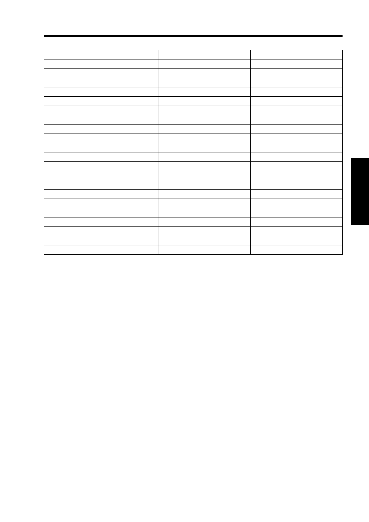
GL-MS4011SG Short focal length lens
Projection Screen Size (Diagonal Length) Image Width Projection distance
50" (Approx. 1.27 m) 1.10 m 1.16 m
60" (Approx. 1.52 m) 1.31 m 1.41 m
70" (Approx. 1.78 m) 1.53 m 1.66 m
80" (Approx. 2.03 m) 1.75 m 1.91 m
90" (Approx. 2.29 m) 1.97 m 2.16 m
100" (Approx. 2.54 m) 2.19 m 2.41 m
110" (Approx. 2.79 m) 2.41 m 2.66 m
120" (Approx. 3.05 m) 2.63 m 2.91 m
130" (Approx. 3.30 m) 2.85 m 3.17 m
140" (Approx. 3.56 m) 3.07 m 3.42 m
150" (Approx. 3.81 m) 3.29 m 3.67 m
160" (Approx. 4.06 m) 3.51 m 3.92 m
170" (Approx. 4.32 m) 3.73 m 4.17 m
180" (Approx. 4.57 m) 3.94 m 4.42 m
190" (Approx. 4.83 m) 4.16 m 4.67 m
200" (Approx. 5.08 m) 4.38 m 4.92 m
210" (Approx. 5.33 m) 4.60 m 5.17 m
220" (Approx. 5.59 m) 4.82 m 5.43 m
230" (Approx. 5.84 m) 5.04 m 5.68 m
240" (Approx. 6.10 m) 5.26 m 5.93 m
250" (Approx. 6.35 m) 5.48 m 6.18 m
NOTE:
● The distance indicated in the table is an estimated value when an image with a resolution of 40962400 is projected.
Please use them as reference during installation.
19
Page 20
Connection and Installation
Connecting Video Signals of the Computer
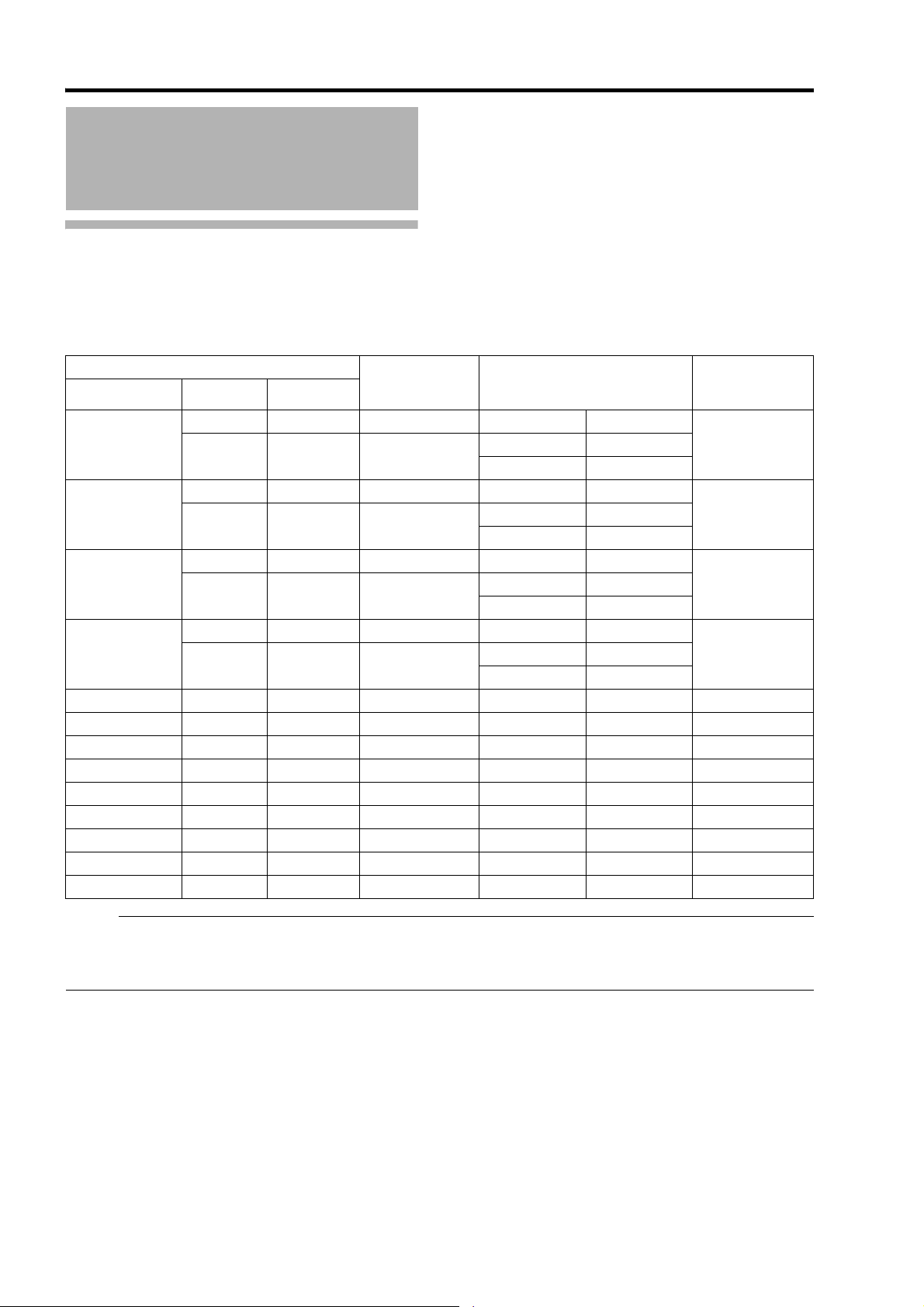
Connection During Single-Screen Mode Display
The single-screen mode displays signals (up to four signals) from a computer as a single video image.
To select to the single-screen mode, set ADisplay ModeB in the Setting menu to ASingleB. (A Page 38)
Possible Input Signals and Projected Image
Computer Projector
Resolution Channel Link Status
2ch Dual DVI 1, DVI 3 2 Stripes 20482400
40962400
40962160
38402400
38402160
20481200 1ch Single DVI 1 Normal 20481200 40962400
20481080 1ch Single DVI 1 Normal 20481080 40962160
19201200 1ch Single DVI 1 Normal 19201200 38402400
19201080 1ch Single DVI 1 Normal 19201080 38402160
1200 1ch Single DVI 1 Normal 16001200 32002400
1600
12801024 1ch Single DVI 1 Normal 12801024 25602048
1024768 1ch Single DVI 1 Normal 1024768 20481536
800600 1ch Single DVI 1 Normal 800600 16001200
640480 1ch Single DVI 1 Normal 640480 1280960
4ch Single DVI 1 to DVI 4
2ch Dual DVI 1, DVI 3 2 Stripes 20482160
4ch Single DVI 1 to DVI 4
2ch Dual DVI 1, DVI 3 2 Stripes 19202400
4ch Single DVI 1 to DVI 4
2ch Dual DVI 1, DVI 3 2 Stripes 19202160
4ch Single DVI 1 to DVI 4
Terminal for
Connection
Output Status
Cross 20481200
4 Stripes 10242400
Cross 20401080
4 Stripes 10242160
Cross 19201200
4 Stripes 9602400
Cross 19201080
4 Stripes 9602160
Displayed
Projector Image
40962400
40962160
38402400
38402160
NOTE:
● This projector converts the frame rate to 60 Hz regardless of the synchronizing signal frequency at the computer’s end.
● If the resolution of the PC is 20481200 or lower, images are displayed upon doubling the number of the vertical and
horizontal pixels.
20
Page 21

Normal 2 Stripes
OPERATE I/B
DVI 3
USB
LAN
RS-232C
STANDBY/ON
CONTROL
LAMP
WARNING
DVI 4
DVI 1
DVI 2
4 Stripes Cross
DVI 3DVI 1DVI 1
DVI 4DVI 3DVI 2DVI 1 DVI 1
DVI 2
DVI 4DVI 3
Connection During Single-Screen Mode Display
Below is the connection example for four-channel signals from the computer.
For two-channel signals from the computer, connect to the [DVI 1] and [DVI 3] terminals of this projector.
Desktop Computer
DVI-D Cable (Sold Separately)
To DVI Terminal
NOTE:
● Depending on your DVI-D cable, the signal may attenuate and the image become unstable.
● Use of DVI-D cables compliant with the DDWG standard is recommended.
21
Page 22

Connection and Installation
Connecting Video
Signals of the Computer
(Cont’d)
Connection During Two-Screen/ Four-Screen Mode Display
The two-screen/four-screen mode enables simultaneous display of signals from two or four computers.
To select the two-screen mode, set ADisplay ModeB in the Setting menu to ADoubleB. To select the four-screen mode, set
ADisplay ModeB to ACrossB. (A Page 38)
Possible Input Signals and Projected Image
Computer 1, Computer 2
Resolution Channel Link Status
20481200 1ch Single Normal 20481200
20481080 1ch Single Normal 20481080
19201200 1ch Single Normal 19201200
19201080 1ch Single Normal 19201080
16001200 1ch Single Normal 16001200
12801024 1ch Single Normal 12801024
1024768 1ch Single Normal 1024768
800600 1ch Single Normal 800600
640480 1ch Single Normal 640480
NOTE:
● This projector converts the frame rate to 60 Hz regardless of the synchronizing signal frequency at the computer’s end.
● The respective signals are displayed at the center of the split screen.
● When in the two-screen mode, the screen appears blue (or black depending on the setting) when there is no input.
Two-Screen Mode
(Example) DVI 1: 19201080,
DVI 3: 19201080
4096
Four-Screen Mode
(Example) DVI 1: 20481200, DVI 2: 19201080,
DVI3:1024768, DVI 4: 16001200
Output Status
4096
2400
22
DVI 1 DVI 3
2048
2400
DVI 1
DVI 3
2048
DVI 2
DVI 4
1200
Page 23

Connection Example During Two-Screen Mode
OPERATE I/B
DVI 3
USB
LAN
RS-232C
STANDBY/ON
CONTROL
LAMP
WARNING
DVI 4
DVI 1
DVI 2
OPERATE I/B
DVI 3
USB
LAN
RS-232C
STANDBY/ON
CONTROL
LAMP
WARNING
DVI 4
DVI 1
DVI 2
Desktop Computer
To DVI Terminal
DVI-D Cable (Sold Separately)
Laptop Computer
To DVI Terminal
Connection Example During Four-Screen Mode
Desktop Computer
Laptop Computer
To DVI Terminal
DVI-D Cable
(Sold Separately)
To DVI Terminal
To DVI Terminal
To DVI Terminal
NOTE:
● Depending on your DVI-D cable, the signal may attenuate and the image become unstable.
● Use of DVI-D cables compliant with the DDWG standard is recommended.
23
Page 24

Network Settings
OPERATE I/B
DVI 3
USB
LAN
RS-232C
STANDBY/ON
CONTROL
LAMP
WARNING
DVI 4
DVI 1
DVI 2
OPERATE I/B
DVI 3
USB
LAN
RS-232C
STANDBY/ON
CONTROL
LAMP
WARNING
DVI 4
DVI 1
DVI 2
Connection Using a LAN Cable
Connect this projector, the computer for controlling this
projector, and the switching hub using LAN cables,
followed by configuring the network.
Connection Example
When assigning a static IP address
You can acquire the IP address from the controlling
computer simply by configuring a network that consists of
this projector, the controlling computer, and switching
hub. Please refer to technical books on networks for
details.
Switching Hub
Specifications of PC for Controlling this Projector
OS Windows XP Professional SP2/
Windows XP Home Edition SP2
CPU Pentium3 1 GHz or higher
Memory 256 MB and above
NOTE:
● Make use of Internet Explorer Ver. 6.0.
● Windows is either registered trademark or trademark
of Microsoft Corporation in the United States and/or
other countries.
CAUTION:
● The PC specifications above are reference values for
the application software to run smoothly, and are not
intended to guarantee their operation.
Note that the applications may not run smoothly
depending on the condition of use of the respective
users even when the system requirements are
satisfied.
To Network
Terminal
To L A N
Terminal
NOTE:
● Make use of Cat. 5 (equivalent or higher) straight
100Base-TX LAN cables.
CAUTION:
● When connecting this projector and the controlling
computer for this projector using other network, be
sure to consult the network administrator of the
network in use or refer to technical books on networks.
When assigning IP address from the DHCP
server
Router
(DHCP Server)
LAN1
WAN
LAN2 LAN3 LAN4
LAN
To N e two r k
Terminal
To L A N
Terminal
NOTE:
● Make use of Cat. 5 (equivalent or higher) 100Base-TX
LAN cables.
24
Page 25

Turning On the Main Power
1 Check to ensure that this projector, computer, and switching hub are properly connected
2 Connect the power cord to the power input terminal of this projector
5
CAUTION:
Power Cord
2
(Supplied)
You can secure the power cord to this projector.
A Attach the plug holder to the power cord.
B Insert the plug holder into the projector until the upper and lower securing levers are locked.
3
Securing Levers (Upper and lower)
● Do not connect the power cord when a lens (optional)
is not attached.
AC INLET
3 Insert plug into the power outlet on the wall
4 Remove the lens cap
5 Turn on the main power of the projector to set to [I]
● The [STANDBY/ON], [LAMP], and [WARNING] indicators light up for about 45 seconds, after which the
[STANDBY/ON] indicator turns red.
NOTE:
● The default IP address of all DLA-SH7NL is “192.168.0.2”. If multiple units of DLA-SH7NL are used on the same
network, do not turn on the main power of more than one projector unit at the same time. Doing so will result in
duplication of the IP address, and thereby preventing proper access.
● When using multiple units of DLA-SH7NL, turn on the main power of the second unit and configure accordingly only
after configuration of the first unit is complete. Configure subsequent units using the same procedure.
● When duplication occurs in the IP address, make sure that only one unit of DLA-SH7NL is connected on the same
network (turn off the main power of the other DLA-SH7NL units). Allow a time interval of at least 10 minutes before
accessing. If access fails, turn off the power of all network equipments on the same network, followed by turning them
on again.
25
Page 26

Network Settings
E
D
IP Address Settings
Set the IP address for this projector. There are 2 methods to set the IP address.
Assigning a static IP address
Assigning an IP address from the DHCP Server
Assigning a static IP address
The AIP Address SettingB of this projector is set to ASTATIC IPB (the DHCP client function is OFF) by default.
Upon turning on the power, this projector starts running with the following IP address.
IP Address : 192.168.0.2
Subnet Mask : 255.255.255.0
Default Gateway : 192.168.0.254
IP address setting at the computer
Set the computer to an IP address that enables communication with this projector.
1 Click AStartB and select AControl PanelB
2 Double click ANetwork ConnectionsB
3 Right-click on ALocal AreaB and select APropertiesB
● Check to ensure that the AClient for Microsoft NetworksB and AInternet Protocol(TCP/IP)B check boxes are selected.
4 Select AInternet Protocol(TCP/IP)B and click APropertiesB
5 Set the IP address
Select AUse the following IP addressB
A
B
Set AIP addressB
(For example, use 192.168.0.100 when DLA-SH7NL is in its
default settings)
NOTE:
● Make sure that you take note of the original IP address
before altering.
● When setting, ensure that a duplicate IP address is not
used within the same network environment.
Set ASubnet maskB
C
Set to a value that is appropriate for the setting operation.
Clarify with the network administrator if you have any queries.
(Use 255.255.255.0 when the camera is in its default settings)
When a ADefault gatewayB is present, make use of the IP
address (e.g., 192.168.0.254)
Click AOKB
6 Click AOKB on the ALocal Area Connection PropertiesB screen
26
Page 27

Setting (Changing) the IP address of this
projector
1 Launch the Internet Explorer on the
computer
2 Check if the proxy has been set in the ALAN
SettingB of the Internet Explorer
A Click ATo o ls B and select AInternet OptionsB
B Click AConnectionsB and click ALAN SettingB
C Check if the check for AUse a proxy server for your
LANB has been selected
● If the check mark has been selected, deselect it.
3 Check if the AActive scriptingB of the Internet
Explorer is disabled
A Click AToolsB and select AInternet OptionsB
B Click in the order of ASecurityB ATrusted SitesB
ASitesB
C Deselect the check ARequired server verification
(https:) for all sites in this zoneB
D Enter Ahttp://192.168.0.2B under AAdd this web site
to the zoneB and click AAddB
E Click AOKB
F Select ATrusted SitesB and click ACustom LevelB
G Check if the check for AActive scriptingB under
AScriptingB has been selected
● If the check mark has been deselected, select it.
Deselect the check
Select AEnableB
27
Page 28

Network Settings
Assign
IP Address Settings
(Cont’d)
Assigning a static IP address
(Cont’d)
Enter Ahttp://192.168.0.2B in the address field
4
of the Internet Explorer, and click
● A login screen for this projector appears.
http://192.168.0.2
NOTE:
● When ALAN SettingB in Internet Explorer is set to AUse
a proxy server for your LANB it may not be possible to
designate addresses directly. Change the proxy
settings.
● If a ASecurity WarningB screen appears, click AOKB
and continue.
AGoB
4
7 Click AAdmin.NetworkB in the main menu
host PJ-1
user: advanced
Logout
Main
Image
Setting
Convergence
Lens
Option
Admin.Network
Admin.E-Mail
Admin.Option
Admin.Signal
Power
ON OFF
Lamp Mode
Lamp Information Hide
Lamp Status Time
1 ok 10h59m
2 ok 12h3m
Signal Status
DVI Rate(Hz) Pixel H Pixel V Link
1 60.00 2048 2400 Dual
2
3 60.00 2048 2400 Dual
4
PROJECTION None
Lamp1 Lamp2 AutoBoth
Warning Status
ONOFF
Temperature
Lamp
30.3 deg.C
Outside
30.3 deg.C
Inside
30.3 deg.C
8 Set the IP address for this projector
host PJ-1
user: advanced
Logout
Main
Image
Setting
Convergence
Lens
Option
Admin.Network
Admin.Mail
Admin.Option
Admin.Signal
Host Name Setting
Host Name
IP Address Setting
DHCP Client DHCP
IP Address 192.168.1.100
Subnet Mask 255.255.255.0
Default Gateway 192.168.1.1
Mac Address 01:23:45:67:89:AB
User Login Name/Password Change
User Name root
New Password
Confirm
New Password
Admin. Login Password Change
User Name advanced
New Password
Confirm
New Password
PJZZZZZZ
SET
STATIC IP
SET
Initialize
SET
SET
A
B
C
5 Enter AadvancedB in Login Name
Input Your Login Name & Password
Login Name advanced
Password
LOGIN
6 Click ALOGINB
● The main menu for this projector appears.
NOTE:
● You can alter the user name and password in the
AAdmin.NetworkB menu. Specify a user name and
password of not more than eight single-byte
alphanumeric characters. (A Page 44)
● If you have forgotten the password, please consult
your authorized dealer.
28
A Select ASTATIC IPB in ADHCP ClientB
B Enter the values for AIP AddressB, ASubnet MaskB
and ADefault GatewayB
C Click ASETB
NOTE:
● Access from computers may not be sucessful as this
projector’s IP address has been changed. Set and
change the computer’s IP address when accessing
this projector.
Page 29

Assigning IP Address from the
OPERATE I/B
DVI 3
USB
LAN
RS-232C
STANDBY/ON
CONTROL
LAMP
WARNING
DVI 4
DVI 1
DVI 2
DHCP Server
The IP address is automatically assigned by the DHCP
server.
1 After connecting, turn on the main power
● Refer to Page 24 on the details of connection.
● Refer to Page 25 on procedures to turn on the main
power.
2 Set the ADHCP ClientB setting of this
projector to ADHCPB
● The ADHCP ClientB of this projector is set to
ASTATIC IPB (the DHCP client function is OFF) by
default. When assigning an IP address from the
DHCP server, access this projector from the
computer to alter the settings. For details on the
setting procedures, refer to ASetting (Changing) the
IP address of this projectorB. (A Page 27)
NOTE:
● Please consult the network administrator on the IP
address assigned to this projector.
● When ADHCP ClientB is set to ADHCPB, and if the
projector is started up in a LAN where a DHCP server
does not exist, the projector will start up using the
default IP address instead.
CAUTION:
● Configure the DHCP server such that the same IP
address is assigned to the AMac AddressB of this
projector by the DHCP server at all times. Connection
may fail if the above setting is not performed.
Using the Mail Delivery Feature
This feature enables delivery of mail (error message) to
the preset e-mail address when error occurs inside this
projector unit.
Connection Example (When DHCP Server is Used)
To Internet Connection
LAN1
WAN
DHCP Server
LAN2 LAN3 LAN4
To LAN Terminal
ADSL modem, etc.
ETHER
LAN
Connecting this projector and the computer
using a USB cable
You can connect this projector and the controlling
computer using a USB cable.
● You need to install a driver in order to connect the
projector and computer using a USB cable.
NOTE:
● For details on the installation of the USB driver,
please consult your authorized dealer.
29
Page 30

Operation and Settings
Projecting Image
If setting for this projector is not completed, refer to AUser
Settings MenuB(A Page 33) upon turning on the power
and configure the settings accordingly.
Once the basic settings are configured, this projector can
be used by simply performing the following operation
procedures.
PREPARATION:
● Remove the lens cap.
●
Connect this projector to the computer. (APage 21, 23)
● Connect the LAN cable. (A Page 24)
3 Adjust the zoom ratio (screen size) (when
zoom lens is in use)
You can adjust the focus using the AZoomB item of the
Lens menu.
host PJ-1
user: root
Logout
Shift
Focus
Main
Image
Setting
Convergence
Lens
Option
Zoom
+
w
_
T
Test Pattern
OFF OFF
U
LR
D
SET
1 Set this projector to the standby mode, and
display the main menu
● Refer to ATurning On the Main PowerB
(A Page 25), and steps 4 to 6 of AAssigning a
static IP addressB (A Page 28).
● The [STANDBY/ON] indicator lights up in red.
2 Click the AONB button under the APowerB
item of the main menu to project the image
● The power of this projector turns on, and formatting
is done taking a few minutes. A gray image will be
displayed during formatting. The projected image
appears once formatting ends.
● The [STANDBY/ON] indicator lights up in green.
host PJ-1
user: root
Logout
Main
Image
Setting
Convergence
Lens
Option
Power
ON OFF
Lamp Mode
Lamp Information Hide
Lamp Status Time
1 ok 10h54m
2 ok 11h58m
Signal Status
DVI Rate(Hz) Pixel H Pixel V Link
1 60.00 2048 2400 Dual
2
3 60.00 2048 2400 Dual
4
PROJECTION None
Lamp1 Lamp2 AutoBoth
NOTE:
● You can also turn on the power by pressing the
[OPERATE I/B] button on the projector unit for more
than one second.
● The image may flicker for a few seconds immediately
after projection starts. This is not a malfunction.
● After the lamp lights up, it takes about 1 minute or
longer for the brightness of the video image on the
screen to stabilize.
Warning Status
ONOFF
Temperature
Lamp
26.8 deg.C
Outside
26.3 deg.C
Inside
34.0 deg.C
To enlarge the screen size:
Press the AWB (Wide) end of AZoomB
To reduce the screen size:
Press the ATB (Tele) end of AZoomB
NOTE:
● The screen size changes each time you click on the
inner buttons ( / ). (Fine control)
The outer buttons ( / ) change the screen size when
they are depressed. (Coarse control)
4 Adjust the position of the projection screen
You can adjust the focus using the AShiftB item of the
Lens menu.
To shift the image upward:
Press the AUB end of AShiftB
To shift the image downward:
Press the ADB end of AShiftB
To shift the image rightward:
Press the ARB end of AShiftB
To shift the image leftward:
Press the ALB end of AShiftB
NOTE:
● When a zoom lens is used, the adjustment range for
lens shift is between 0 % to ±50 % in the vertical
direction, and between 0 % to ±25 % in the horizontal
direction (during single-screen display).
When a short focal length lens is used, the adjustment
range for lens shift is between 0 % to ±15 % in the
vertical direction, and between 0 % to ±5 % in the
horizontal direction (during single-screen display).
(A Page 16)
● The position changes each time you click on the inner
buttons ( / ). (Fine control)
The image shifts when the outer buttons ( / ) are
depressed. (Coarse control)
● The lens shift feature does not function if the lens
mechanism is secured.( A Page 16 ALens Fixation
MechanismB)
30
Page 31

5 Adjust the focus
You can adjust the focus using the AFocusB item of the
Lens menu.
To move the focus point closer:
Press the A+B (Near) end of AFocusB
To move the focus point away:
Press the AB (Far) end of AFocusB
NOTE:
● The focus changes each time you click on the inner
buttons ( / ). (Fine control)
The outer buttons ( / ) change the focus when they
are depressed. (Coarse control)
8 Turn the main power at the rear of the
projector unit to off [O]
● The [STANDBY/ON] indicator on the projector unit
goes off.
CAUTION:
● Do not turn off the main power supply switch when in
the cool down mode. Doing so may shorten the lamp
life and cause a malfunction.
● Upon using, attach the lens cap to prevent soiling of
the lens.
● When the projector is not to be used for a long time,
disconnect the power plug.
6 Select a screen mode for projection
You can specify the screen mode using ADisplay
ModeB of the Setting menu. (A Page 38)
host PJ-1
user: root
Logout
Main
Image
Setting
Convergence
Lens
Option
Input Level
0-255(PC)
Display Mode
1133
16-235
12
4
NOTE:
● The projected image varies according to the mode of
connection. (A Page 21, 23)
7 Click the AOFFB button under the APowerB
item of the Main menu to end the projection
● The projector switches to the cool down mode, and
the [STANDBY/ON] indicator appears blinking in
red.
● A gray image will be displayed for a maximum
duration of 2 minutes during the ending process
only after several hours of image projection. The
lamp starts cooling down thereafter.
● After exiting the cool down mode, the projector
switches automatically to the standby mode, and
the [STANDBY/ON] indicator lights up in red.
● You can also turn off the power by pressing the
[OPERATE I/B] button on the projector unit for
more than one second.
Useful Features During Projection
Hiding the projected image temporarily
The projected image can be hidden by clicking the AONB
button under the AHideB item of the Main menu or Image
menu.
● When the image is not displayed, pressing AOFFB
under the AHideB item to display the hidden image.
host PJ-1
user: root
Logout
Main
Image
Setting
Convergence
Lens
Option
NOTE:
● When the image is hidden, the [STANDBY/ON]
indicator appears blinking in green.
Brightness
Contrast
Gamma Hide
-30 +30
Red
-30 +30
Green
-30 +30
Blue
-30 +30
Red
-30 +30
Green
-30 +30
Blue
0
0
0
0
0
0
ONOFFB CA
Cool down mode
The cool down mode is a function that cools down the
lamp for an interval of about 180 seconds after
projection ends (ending process).
This function is to prevent deformation and damage of
the internal components of the projector due to heat
from the overheated lamp. It also prevents lamp
breakage and shortened lamp life.
● When the projector is in the cool down mode, the
[STANDBY/ON] indicator appears blinking in red.
● Do not shut down the main power supply or unplug
the power cord when in the cool down mode. Also,
do not block the air inlets and vent holes. Doing so
may shorten the lamp life and cause a malfunction.
31
Page 32

Operation and Settings
Displaying the Menu
1 Enter the IP address assigned in the address
field of the Internet Explorer, and click AGoB
(A Page 28)
● Example: When IP address assigned is
A192.168.0.2B, enter
Ahttp://192.168.0.2B.
http://192.168.0.2
1
3 Click ALOGINB
● The main menu for this projector appears.
NOTE:
● You can alter the user name and password in the
AAdmin.NetworkB menu. Specify a user name and
password of not more than eight single-byte
alphanumeric characters. (A Page 44)
NOTE:
● When ALAN SettingB in Internet Explorer is set to
AUse a proxy server for your LANB it may not be
possible to designate addresses directly. Change the
proxy settings.
● If a ASecurity WarningB screen appears, click AOKB
and continue.
2 Enter the login name and the password in the
ALogin NameB and APasswordB fields
respectively
Input Your Login Name & Password
Login Name
Password
LOGIN
NOTE:
● If you have forgotten the password, please consult
your authorized dealer.
32
Page 33

User Settings Menu
After installation and connection are complete, perform the necessary adjustment and setting.
Operate the menus using the computer’s browser to make adjustments and configure settings.
User Settings Menu Structure
Page Menu Name Page Display Item Simplified Description of Item
(1) Main Power
Warning Status
Lamp Mode
Lamp Information
Signal Status
Temperature
Hide
(2) Image Brightness
Contrast
Gamma
Hide
(3) Setting Input Level
Display Mode
(4) Convergence Red
Blue
Test Pattern
(5) Lens Zoom
Focus
Shift
Test Pattern
(6) Option Flip
Lamp Power
Back Color
Message Display
Test Pattern
Power ON/OFF operation
Error code display
Illumination mode setting
Lamp information display
Input signal information display
Projector’s interior temperature display
Mute operation
Brightness adjustment
Contrast adjustment
Gamma setting
Mute operation
Input level setting
Display method setting
Pixel position adjustment
Pixel position adjustment
Test pattern setting
Zoom adjustment
Focus adjustment
Image position adjustment
Test pattern setting
Image inversion setting
Lamp power setting
Background color setting
Message display setting
Test pattern setting
33
Page 34

Operation and Settings
User Settings Menu
(Cont’d)
(1) Main Menu
This menu displays the ON/OFF status of the power supply and information on signals input to the projector.
host PJ-1
user: root
Logout
Main
Image
Setting
Convergence
Lens
Option
Power
ON OFF
Lamp Mode
Lamp Information Hide
Lamp Status Time
1 ok 10h54m
2 ok 11h58m
Signal Status
DVI Rate(Hz) Pixel H Pixel V Link
1 60.00 2048 2400 Dual
2
3 60.00 2048 2400 Dual
4
PROJECTION None
Lamp1 Lamp2 AutoBoth
Warning Status
ONOFF
Temperature
Lamp
26.8 deg.C
Outside
26.3 deg.C
Inside
34.0 deg.C
NOTE:
● When the power of this unit is off (main power is on), the AMainB, AImageB, ASettingB, AConvergenceB, ALensB and
AOptionB menus will be grayed out and will not be selectable.
34
Page 35

indicates the factory default.
Item Setting Value Description
Power ON
OFF
For turning on/off the lamp selected in ALamp ModeB.
ON : Turns on the lamp.
OFF : Turns off the lamp.
NOTE:
● The following operating modes of the projector are displayed to the
right of the OFF button.
STANDBY : Standby (OFF)
PROJECTION : Lamp Illuminated (ON)
FAN ENABLE : FAN Enable (OFFON)
LAMP ENABLE : LAMP Enable (OFFON)
DEVICE ENABLE : Elemental Device Enable (OFFON)
COOLING : Cooling (OFF)
EMERGENCY : Error Occurred (Cooling not performed)
EMERGENCY COOLING : Error Occurred (Cooling performed)
● When in the standby mode, clicking the ON button each time
switches the mode in the sequence of STANDBYDEVICE
ENABLELAMP ENABLEFAN ENABLEPROJECTION.
● Clicking the OFF button when the power is on switches the projector
to the cooling mode. The power of the projector cannot be turned on
during the cooling process (180 seconds).
Warning Status ^ Displays the latest error number.
NOTE:
● For details on the error code and description, please refer to
AWarning StatusB. (A Page 55)
● ANoneB is displayed when no error is detected.
Lamp Mode Q Both
Lamp1
Lamp2
Auto
For selecting the lamp to turn on during power on.
Both : Selects both lamps.
Lamp1 : Selects only Lamp 1.
Lamp2 : Selects only Lamp 2.
Auto : Selects only the lamp with the least lamp time.
However, ALamp1B is selected when both lamps have
the same lamp time.
NOTE:
● This setting is only available in the ASTANDBYB, ACOOLINGB,
AEMERGENCYB and AEMERGENCY COOLINGB operating modes.
Lamp Information ^ For displaying the information on Lamp 1 and 2.
Status
ON : Lamp illuminated
OFF : Lamp off
Failed : The lamp fails to light up even though the operation of
illuminating the lamp is performed.
Time Lamp time (in minutes)
35
Page 36

Operation and Settings
User Settings Menu
(Cont’d)
(1) Main Menu (Cont’d)
indicates the factory default.
Item Setting Value Description
Signal Status
DVI
Rate(Hz)
Pixel H
Pixel V
Link
Temperature
Lamp
Outside
Inside
Hide Q OFF
^
^
^
^
^
^
^
^
ON
Displays information on the input signals.
DVI : Displays the DVI input terminal number.
Rate(Hz) : Displays the vertical frequency.
Pixel H : Displays the horizontal resolution.
Pixel V : Displays the vertical resolution.
Link : Displays the link status of the DVI terminal.
NOTE:
● This item is not displayed when there is no signal input.
● The text color of Rate (vertical frequency) turns red in the case of
interlaced signal. And the text turns white in the case of progressive
signal.
Displays the interior temperature of the projector.
Lamp : Lamp’s ambient temperature
Outside : External temperature
Inside : Internal temperature
NOTE:
● The color of the text turns red if the temperature becomes abnormal.
● The text appears white at normal temperature.
Enables temporary hiding of the image.
OFF : Do not hide image.
ON : Hide image.
NOTE:
● When the image is hidden, the ASTANDBY/ONB indicator appears
blinking in green.
36
Page 37

(2) Image Menu
This menu is used for adjusting the picture quality.
host PJ-1
user: root
Logout
Main
Image
Setting
Convergence
Lens
Option
indicates the factory default.
Item Setting Value Description
Brightness
Red
-30 to +30
(Default Value: 0)
Green
-30 to +30
(Default Value: 0)
Blue
-30 to +30
(Default Value: 0)
Brightness
-30 +30
Red
-30 +30
Green
-30 +30
Blue
Contrast
-30 +30
Red
-30 +30
Green
-30 +30
Blue
Gamma Hide
0
0
0
0
0
0
For adjusting the brightness of the red, green, and blue colors.
ONOFFB CA
Contrast
Red
-30 to +30
(Default Value: 0)
Green
-30 to +30
(Default Value: 0)
Blue
-30 to +30
(Default Value: 0)
Gamma Q A
B
C
Hide Q OFF
ON
For adjusting the contrast of the red, green, and blue colors.
For specifying the tone characteristics of the image.
A : Sets gamma to “2.2”.
B : Sets gamma to “1.8”.
C : Sets gamma to “2.6”.
Enables temporary hiding of the image.
OFF: Do not hide image.
ON : Hide image.
NOTE:
● When the image is hidden, the ASTANDBY/ONB indicator appears
blinking in green.
37
Page 38

Operation and Settings
User Settings Menu
(Cont’d)
(3) Setting Menu
This menu is used for specifying the input level of the terminal and the display mode.
host PJ-1
user: root
Logout
Main
Image
Setting
Convergence
Lens
Option
indicates the factory default.
Item Setting Value Description
Input Level Q 0-255(PC)
16-235
Display Mode Q Single
Double
Cross
Input Level
0-255(PC)
Display Mode
11
Single Double Cross
16-235
3
For specifying the input level of the video signals.
0-255(PC) : Set to this value under normal circumstances.
16-235 : For specifying when the signal level is between 16
For specifying the display mode of the projection screen.
Single : Displays input signals on a single screen.
Double : Displays two different input signals on two screens.
The left screen displays images of the DVI 1 terminal,
and the right screen displays images of the DVI 3
terminal.
Cross : Displays four different input signals on four screens.
The top left screen displays images of the DVI 1
terminal, the top right screen displays images of the DVI
2 terminal, the bottom left screen displays images of the
DVI 3 terminal, while the bottom right screen displays
images of the DVI 4 terminal.
NOTE:
● Please refer to AConnecting Video Signals of the ComputerB for
details. (A Page 20 to 23)
12
3
4
(Signal level 0 to 255)
and 235.
38
Page 39

(4) Convergence Menu
This menu is used for correcting color shifts in the optical system.
host PJ-1
user: root
Logout
Main
Image
Setting
Convergence
Lens
Option
Red
U
LR
D
Test Pattern
OFF OFF
Blue
U
LR
D
SET
indicates the factory default.
Item Setting Value Description
Red ^ For adjusting the horizontal/vertical position of red and blue colors on
the image.
Blue ^
NOTE:
● The green color value is fixed.
● The outer buttons are used for adjustment in units of 1/4 pixels, and
the inner buttons in units of 1/10 pixels.
● When the image is flipped horizontally or vertically, the horizontal and
vertical directions are reversed.
● Use images with a clear outline (such as Color Cross Hatch patterns
available in this projector) for adjustment.
CAUTION:
● When the movement exceeds the limit, the color of the button turns
red.
Test Pattern Q OFF
Color Bars
Color Cross Hatch
Cross Hatch
Staircase
Ramp
Flat
For projecting the test pattern.
OFF : Do not display the test pattern.
Color Bars : Displays the color bar.
Color Cross Hatch
: Displays the color cross hatch pattern.
Cross Hatch : Displays the cross hatch pattern.
Staircase : Displays the staircase (white color).
Ramp : Displays the ramp pattern (white color).
Flat : Displays the flat pattern (white color).
39
Page 40

Operation and Settings
User Settings Menu
(Cont’d)
(5) Lens Menu
This menu is used for adjusting the projection lens.
host PJ-1
user: root
Logout
Main
Image
Setting
Convergence
Lens
Option
Item Setting Value Description
Zoom ^ For adjusting the zoom ratio (screen size).
Zoom
Test Pattern
Focus
w
T
+
_
OFF OFF
Shift
U
LR
D
SET
NOTE:
● The zoom position changes each time the inner button is clicked.
The zoom position changes when the outer button is depressed.
CAUTION:
● Due to backlash, the response may not be immediate.
Focus ^ For adjusting the focus position.
NOTE:
● The focus position changes each time the inner button is clicked.
The focus position changes when the outer button is depressed.
CAUTION:
● Due to backlash, the response may not be immediate.
Shift ^
For adjusting the horizontal and vertical positions of the projection screen.
NOTE:
● The shift position changes each time the inner button is clicked.
The shift position changes when the outer button is depressed.
CAUTION:
● When the movement exceeds the limit, the color of the button turns
red.
● Due to backlash, the response may not be immediate.
Test Pattern ^ For projecting the test pattern.
NOTE:
● Same as ATest PatternB in the Convergence Menu. (A Page 39)
40
Page 41

(6) Option Menu
This menu is used for specifying settings for the method of screen display, lamp brightness and others.
host PJ-1
user: root
Logout
Main
Image
Setting
Convergence
Lens
Option
Flip
Horz.
ON OFF
Lamp Power
High Low
Message Display
ON OFF
Test Pattern
OFF OFF
Ver t .
Back Color
Blue Black
indicates the factory default.
Item Setting Value Description
Flip
Horz.
Vert.
ON
Q OFF
ON
Q OFF
For specifying settings if images are vertically or horizontally flipped
when they are projected from the opposite side of the screen, or when
mirrors are used for projection.
ON : Flips image horizontally.
OFF : Do not flip image horizontally.
ON : Flips image vertically.
OFF : Do not flip image vertically.
Lamp Power Q High
For switching the brightness of the lamp between Low and High.
Low
Back Color Q Blue
Black
For specifying the background color during message display or when
projection fails, such as when there is no input signal.
Blue : Sets the screen to blue color.
Black : Sets the screen to black color.
Message
Display
ON
Q OFF
For specifying whether to display the message.
ON : Displays message.
OFF : Do not display the test pattern.
CAUTION:
● When AOFFB is set, the ANo InputB, AOut of RangeB and ALamp
Time OverB messages will not be displayed on the screen.
Test Pattern ^ For projecting the test pattern.
NOTE:
● Same as ATest PatternB in the Convergence Menu. (A Page 39)
ON OFF
SET
41
Page 42

Memo :
42
Page 43

Administrator Settings Menu
After installation and connection are complete, perform the necessary adjustment and setting.
Operate the menus using the computer’s browser to make adjustments and configure settings.
Administrator Settings Menu Structure
For details on page menu (1) to (6), refer to AUser Settings MenuB (A Page 33 to 41).
Page Menu Name Page Display Item Simplified Description of Item
(1) Main Power
Warning Status
Lamp Mode
Lamp Information
Signal Status
Temperature
Hide
(2) Image Brightness
Contrast
Gamma
Hide
(3) Setting Input Level
Display Mode
(4) Convergence Red
Blue
Test Pattern
(5) Lens Zoom
Focus
Shift
Test Pattern
(6) Option Flip
Lamp Power
Back Color
Message Display
Test Pattern
(7) Admin.Network Host Name Setting
IP Address Setting
User Login Password Change
Admin. Login Password Change
(8) Admin.E-mail E-Mail Setting
Test Mail
(9) Admin.Option Color Depth
Frame Lock
Mecha. Shutter
High Altitude
Lamp Time Reset
(10) Admin.Signal Force Signal
Display Mode
Signal Status
EDID
Power ON/OFF operation
Error code display
Illumination mode setting
Lamp information display
Input signal information display
Projector’s interior temperature display
Mute operation
Brightness adjustment
Contrast adjustment
Gamma setting
Mute operation
Input level setting
Display method setting
Pixel position adjustment
Pixel position adjustment
Test pattern setting
Zoom adjustment
Focus adjustment
Image position adjustment
Test pattern setting
Image inversion setting
Lamp power setting
Background color setting
Message display setting
Test pattern setting
Host name setting
IP address setting
User login setting
Administrator login setting
E-mail setting
Test e-mail setting
Color balance setting
Frame synchronization setting
Mechanical shutter setting
High altitude mode setting
Resetting lamp time
Input/output signal setting
Display method setting
Input signal information display
EDID information rewrite
43
Page 44

Operation and Settings
Administrator Settings
Menu (Cont’d)
(7) Admin.Network Menu
For configuring the network settings.
host PJ-1
user: advanced
Logout
Main
Image
Setting
Convergence
Lens
Option
Admin.Network
Admin.Mail
Admin.Option
Admin.Signal
indicates the factory default.
Item Setting Value Description
Host Name Setting
Host Name
IP Address Setting
DHCP Client
IP Address
Subnet Mask
Default Gateway
Mac Address
Host Name Setting
IP Address Setting
Default Gateway 192.168.1.1
User Login Name/Password Change
New Password
New Password
Admin. Login Password Change
New Password
New Password
^
(Default Value:
PJZZZZZZ)
DHCP
Q STATIC IP
(Default Value:
192.168.0.2)
(Default Value:
255.255.255.0)
(Default Value:
192.168.0.254)
^
Host Name
DHCP Client DHCP
IP Address 192.168.1.100
Subnet Mask 255.255.255.0
Mac Address 01:23:45:67:89:AB
User Name root
Confirm
User Name advanced
Confirm
PJ ZZZZZZ
STATIC IP
SET
SET
Initialize
SET
SET
For specifying the host name.
NOTE:
● You can change it to a random name. You can input up to 8
characters using single-byte alphanumeric characters and “ ”.
● “ZZZZZZ” of the default value displays the lower 3 bytes of the
MAC address of this projector.
For configuring the network settings.
DHCP : Select this to acquire the IP address from the
DHCP server automatically.
STATIC IP : Select this to configure the IP address manually.
IP Address : Specify the IP address.
Subnet Mask : Specify the subnet mask.
Default Gateway : Specify the default gateway.
Mac Address : Displays the MAC address. (Cannot be
specified)
44
Page 45

Item Setting Value Description
User Login Name/
Password Change
User Name
New Password
Confirm New
Password
Initialize
Admin. Login Password
Change
User Name
New Password
Confirm New
Password
Initialize
root
^
^
^
advanced
^
^
^
For changing the login name and password.
User Name : For changing the login name.
New Password : For changing the login password.
Confirm New Password : Re-enter the new password. (For
confirmation)
Initialize : For resetting the username/password.
NOTE:
● You can change it to a random name. You can input up to 8
characters using single-byte alphanumeric characters and “ ”.
● If you have forgotten the password, please consult any nearby JVC
servicing center.
For changing the administrator’s password.
User Name : Cannot be changed. (fixed)
New Password : For changing the login password.
Confirm New Password : Re-enter the new password. (For
confirmation)
Initialize : For resetting the password.
NOTE:
● You can change it to a random name. You can input up to 8
characters using single-byte alphanumeric characters and “ ”.
● If you have forgotten the password, please consult your authorized
dealer.
45
Page 46

Operation and Settings
Administrator Settings
Menu (Cont’d)
(8) Admin.E-mail Menu
This menu is for configuring the mail settings,
which sends out an error message to the computer of the preset address when an abnormality occurs within this projector.
host PJ-1
user: advanced
Logout
Main
Image
Setting
Convergence
Lens
Option
Admin.Network
Admin.E-Mail
Admin.Option
Admin.Signal
E-Mail Setting
E-Mail
E-Mail Sender
E-Mail Address
SMTP Server Address
E-Mail Auth.
Auth. Type
Auth. User Account
Auth. Password
Port No.
Tset Mail
Error message sent from this projector
(Example) When error occurs at the DD-RB board
Sender
ZZZZZZ (setting value for AE-Mail SenderB)
ON OFF
user@localhost
user@localhost
1.1.1.1
ON OFF
LOGIN CRAM-MD5PLAN
465 58725
SET
SEND
Mail title
4KPJU2 report mail
Message
Error Code
System Time
Lamp1 Time
Lamp2 Time
Lamp Temp.
Inside Temp.
Outside Temp.
32 “Trouble with DD-RB circuit board.”
106 h 57 m
41h 59 m
41h 31 m
42 deg.C
40 deg.C
24 deg.C
NOTE:
● Refer to the code in the AWarning StatusB for the error code. (A Page 55)
46
Page 47

indicates the factory default.
Item Setting Value Description
E-Mail Setting
For configuring the e-mail feature.
E-Mail
E-Mail Sender ^
E-Mail Address ^
SMTP Server
Address
E-Mail Auth. ON
Auth. Type Q PLAIN
ON
Q OFF
(Default Value: lower 3
bytes of the MAC address)
(Default Value:
user@localhost)
^
(Default Value: 1.1.1.1)
Q OFF
LOGIN
CRAM-MD5
ON : Use the mail feature.
OFF : Do not use the mail feature.
For specifying the destination e-mail address of this
projector.
For specifying the destination e-mail address.
NOTE:
● Specify an address up to a maximum of 64 characters.
● Make use of single-byte alphanumeric characters and
A-B A.B A_B A@B.
For specifying the address of the outgoing mail server
(SMTP).
NOTE:
● Specify an address up to a maximum of 15 characters.
● Make use of numbers and A.B.
ON : Enable the e-mail authentication feature.
OFF : Disable the e-mail authentication feature.
For configuring the e-mail authentication type.
PLAIN : Set e-mail authentication to APLAINB.
LOGIN : Set e-mail authentication to ALOGINB.
CRAM-MD5 : Set e-mail authentication to ACRAM-
MD5B.
Auth. User
Account
^ For configuring the account name during e-mail
authentication.
NOTE:
● Specify an address up to a maximum of 31 characters.
●
Make use of single-byte alphanumeric characters and A-B.
Auth. Password ^ For configuring the password during e-mail authentication.
NOTE:
● Specify an address up to a maximum of 31 characters.
●
Make use of single-byte alphanumeric characters and A-B.
Port No. Q 25
465
587
Set ^ The details of the configuration will be saved.
Test Mail ^ When the ASENDB button is clicked, the test mail with the
For configuring the SMTP server port number when using
the e-mail authentication feature.
contents configured in the E-Mail Setting will be sent.
47
Page 48

Operation and Settings
Administrator Settings
Menu (Cont’d)
(9) Admin.Option Menu
This menu is used for specifying settings including image and option, and for resetting the lamp.
host PJ-1
user: advanced
Logout
Main
Image
Setting
Convergence
Lens
Option
Admin.Network
Admin.E-Mail
Admin.Option
Admin.Signal
Color Depth
8bit 12bit
Mech. Shutter
ON
Installation Style
A B C
Lamp Time Reset
Lamp1 11h1m
Lamp2 12h5m
OFF
Reset
Reset
Frame Lock
ON OFF
High Altitude
ON OFF
indicates the factory default.
Item Setting Value Description
Color Depth Q 8bit
For configuring the color balance.
12bit
Frame Lock Q ON
For configuring the frame synchronization of each DVI input.
OFF
Mech. Shutter ON
Q OFF
High Altitude ON
For configuring to ON/OFF the Mech. Shutter (model number: PKVS4MSG, optional, sold separately). Click ON to operate the Mecha
Shutter.
Configure to ON when using at high altitude (above 1,500 m).
Q OFF
Installation
Style
Q B
A
For configuring the installation method (orientaion mode) of the
projector.
C
A : Orientation mode A (upward installation)
B : Orientation mode B (horizontal installation/normal mode)
C : Orientation mode C (downward installation)
Lamp Time
^ For resetting the lamp time of Lamp 1 and 2.
Reset
Lamp1
Lamp2
48
Page 49

(10) Admin.Signal Menu
This menu is for configuring settings such as display format, and for rewriting EDID.
Main
Image
Setting
Convergence
Lens
Option
Admin.Network
Admin.E-Mail
Admin.Option
Admin.Signal
Force Signal
OFF
OFF
Signal Status
DVI Rate(Hz) Pixel H Pixel V Link
1 60.00 2048 2400 Dual
2
3 60.00 2048 2400 Dual
4
Display Mode
11
EDID
3
12
3
4
SET
Browse
host PJ-1
user: advanced
Logout
SET
indicates the factory default.
Item Setting Value Description
Force Signal Q OFF
40962400, None,
Dual
40962400, None,
Single
20482400,
2Stripe, Dual
20482400,
2Stripe, Single
20481200,
Cross, Dual
20481200,
Cross, Single
10242400,
4Stripe, Dual
10242400,
4Stripe, Single
Single Double Cross
For forcibly configuring the output signal. Make use of this setting
when there is no display due to configuration changes at the input
source.
NOTE:
● Some portions of the image may not be displayed and the image
may become noisy.
OFF : Turns off the display by force.
40962400, None, Dual
: Displays a normal screen using dual link.
40962400, None, Single
: Displays a normal screen using single link.
20482400, 2Stripe, Dual
: Displays a 2 stripes screen using dual link.
20482400, 2Stripe, Single
: Displays a 2 stripes screen using single link.
20481200, Cross, Dual
: Displays a cross screen using dual link.
20481200, Cross, Single
: Displays a cross screen using single link.
10242400, 4Stripe, Dual
: Displays a 4 stripes screen using dual link.
10242400, 4Stripe, Single
: Displays a 4 stripes screen using single link.
49
Page 50

Operation and Settings
Administrator Settings
Menu (Cont’d)
(10) Admin.Signal Menu (Cont’d)
indicates the factory default.
Item Setting Value Description
Signal Status
DVI
Rate(Hz)
Pixel H
Pixel V
Link
Display Mode Q Signal
EDID ^ For rewriting EDID.
^
^
^
^
^
Double
Cross
Displays information on the input signals. Same as ASignal StatusB in the
User Menu.
DVI : Displays the DVI input terminal number.
Rate(Hz) : Displays the vertical frequency.
Pixel H : Displays the horizontal resolution.
Pixel V : Displays the vertical resolution.
Link : Displays the link status of the DVI terminal.
NOTE:
● This item is not displayed when there is no signal input.
● The text color of Rate (vertical frequency) turns red in the case of
interlaced signal. And the text turns white in the case of progressive
signal.
For specifying the display mode of the projection screen. Same
configuration as ADisplay ModeB in the User Menu.
Signal : Displays input signals on a single screen.
Double : Displays two different input signals on two screens. The
Cross : Displays four different input signals on four screens.
Click the ABrowseB button and select an EDID file.
Click the ASETB button to start writing.
Write AOKB will be displayed for each channel. “NG (number)” is displayed
when writing fails.
left screen displays images of the DVI1 terminal, and the
right screen displays images of the DVI3 terminal.
The top left screen displays images of the DVI1 terminal,
the top right screen displays images of the DVI2
terminal, the bottom left screen displays images of the
DVI3 terminal, while the bottom right screen displays
images of the DVI4 terminal.
50
Error Code
1: System error
7: Unable to execute due to power off
8: Unable to rewrite due to DVI cable connection
CAUTION:
● Do not turn off the power during rewrite.
● The EDID file capacity is within 256 byte.
● Rewriting to individual channel is not available.
● It is not possible to move on to other pages during rewrite.
NOTE:
● EDID: Extended Display Information Data
A data to describe the specifications (resolution, model number, etc.) of
the projector. The compatible transmitting device will output the
optimum video signal based on this data.
Page 51

Others
Troubleshooting
Check the following points before sending this product for repair.
The following phenomena are not malfunctions.
If there is no abnormality on the screen when the phenomena below appear, they are not malfunctions.
● The top or front part as well as the rear of the projector unit is hot
● A creaking sound is heard from the projector
● Device noise is heard from the interior of the projector
● There is color bleeding on the screen
When the projector fails to run properly due to external noises, perform the following operations.
A Check to ensure that the power is shut down. Unplug the power cord, and insert again.
B Turn on the power of the projector.
A sound maybe heard when the lamp burn out. However, this is not a hazard.
D-ILA devices are manufactured using extremely high-precision technology. However, some of the
pixels may not lit up or remain permanently lit up.
Symptom Probable Cause Corrective Action
Power is not
supplied
Image is dark ● Is the lamp near exhaustion? ● Check the ALamp InformationB setting
Projector works
when the power
is turned on, but
stops abruptly
after a few
minutes
Video image
does not appear
● Is the power cord disconnected? ● Insert the power cord (plug) properly. A Page 25
● Is the main power supply switched
turned on?
● Is the lamp in the cool down mode? ● Turn on the power again after the cool
● Is the lamp protection function
triggered?
(This function is triggered when the
power shuts down such as during
power failures.)
● Are the air inlets and vent holes
blocked?
● Is the temperature of the room high? ● Set the temperature of the room or the
● Are the filters dirty? ● Clean the filters. A Page 58
● Is the lens cap removed? ● Remove the lens cap. A Page 12
● Are devices properly connected? ● Connect the devices correctly. A Page 21,
● Is the power of the connected
devices turned on?
● Are correct signals being output
from the connected devices?
● Are the signals of the connected
devices possible input signals?
● Is the image temporarily hidden? ● Set AHideB of the Main menu or Image
● Turn on the main power supply switch
of the projector unit.
down mode ends.
● Wait till the temperature of the lamp
has gone down. (Turn on the main
power supply switch to run the fan and
cool down the lamp.) Turn on the
power after about 180 seconds.
of the Main menu. When the lamp life
is near its end, please consult your
authorized dealer.
● Turn off the main power supply switch,
and remove the blockage. After
removing, turn on the power again.
surrounding temperature of this
projector to an appropriate level.
● Turn on the power of the connected
devices.
● Configure the connected devices
correctly.
● Check to ensure that they are possible
input signals, and input compatible
signals accordingly.
menu to AOFFB to display the image.
Reference
Page
A Page 25
A Page 31
^
A Page 35
A Page 12 to
14, 31
A Page 60
23
^
^
A Page 20,
22
A Page 31,
36, 37
51
Page 52

Others
Troubleshooting (Cont’d)
Symptom Probable Cause Corrective Action
Video image is
blur
Image is
unusually dark
or bright
Coloring of the
image is poor or
distorted
Projection
position on the
screen has
shifted
Image
disappears
suddenly
Images do not
appear on the
two-screen
mode display
Images do not
appear
immediately
after power is
turned on
The screen does
not darken
immediately
when the
projection has
ended
● Is the projector out of focus? ● Adjust the focus using AFocusB of the
● Is the projection distance too short
or too long?
● Is the brightness level properly
adjusted?
● Is the contrast level properly
adjusted?
● Are the signals of the connected
devices possible input signals?
● Is the input cable correctly
connected?
● Has the setup position of the
projector been shifted?
● Are the video signals correctly
input?
● Are the DVI 1 and DVI 3 terminals
connected for input?
● Formatting is in progress. ● Please wait for a maximum duration of
● The ending process is in progress. ● Please wait for a maximum duration of
Lens menu.
● Set it to a correct distance. A Page 18,
● Adjust accordingly using ABrightnessB
of the Image menu.
● Adjust ALamp PowerB in the Option
menu.
● Adjust accordingly using AContrastB of
the Image menu.
● Check to ensure that they are possible
input signals, and input compatible
signals accordingly.
● Connect the input cable correctly. A Page 21,
● Check the setup position of the
projector.
● Check the signals and connection. A Page 20 to
● To display images in the two-screen
mode, connect the DVI 1 and DVI 3
terminals. The left screen displays
images of the DVI 1 terminal, and the
right screen displays images of the
DVI 3 terminal.
3 minutes for the formatting progress
to end.
2 minutes for the ending progress to
complete after several hours of image
projection.
Reference
Page
A Page 31,
40
19
A Page 37
A Page 41
A Page 37
A Page 20,
22
23
^
23
A Page 22,
23
A Page 30
A Page 31
52
Page 53

What to do when these messages are displayed
Messages are displayed when the lamp life has expired and when there is input of signals that cannot be used.
Message
Lamp Time Over
Message Cause (Details)
● Displayed when the lamp time has exceeded 2000 hours.
The message is displayed for a period of 3 minutes during each
Lamp Time Over
Out of Range
No Input
NOTE:
● The messages will not be displayed under factory default conditions.
● Set AMessage DisplayB in the Option menu to AONB. (A Page 41)
projection.
Replace with a new lamp unit.
For details on replacement of the lamp unit, please consult your
authorized dealer.
● When there is input of video signals that cannot be used with this
unit
Input video signals that can be used.
● When no device is connected to the input terminal
● When the input terminal is connected but there is no signal
Input the video signals.
53
Page 54

Others
Warnings Using Indicators
The lamp time and warning mode are indicated using the indicator.
For indicator displays during normal operation, refer to the note below.
Indicator
No.
10 *1
*1: The indicator lights up in red when in the standby mode, and in green when in the operating mode.
*2: The indicator lights up in red when in the warning mode, and blinks in red when in the cool down mode.
STANDBY/
ON
1
*1
2
3
4 When the lamp goes off during projection
5
6 When the external temperature is unusually high
7 When the internal temperature is unusually high
8 When an abnormality has occurred in the cooling fan
9 When error occurs in the circuit operation
*2
*2 -
LAMP WARNING
Light On
(Yellow)
Blinking
(Yellow)
Blinking
(Yellow)
-
Light On
(Red)
Light On
(Red)
- One of the lamp does not turn on
About time to replace lamp
(Lamp time has exceeded 1900 hours.)
When the lamp life has expired
(Lamp time has exceeded 2000 hours. Message displayed.
(A Page 53))
When lamp does not light up and projection fails
Temperature around the lamp is high
Description
Measures when the warning mode appears
When the projector switches to the warning mode (Nos. 3 to 9), projection stops automatically, and the cooling fan runs for
about 180 seconds.
After the cooling fan stops running, turn off the main power supply switch, and remove the power plug from the outlet.
Perform the following checks and take the corresponding measures.
No. Check Measure
3
4
5
6
7
8
9
If the warning indication is displayed again, turn off the main power supply switch after the cooling fan stops running.
Then pull out the power plug from the power outlet. Call your authorized dealer for repair.
● Check whether the projector has been subject to
shock during operation.
● Check whether the air inlets are blocked by
objects.
● Check to ensure that the external temperature of
the projector is normal.
● Turn on the power again.
● Allow some time for the projector to cool down.
NOTE:
● Indicator display during normal condition.
Indicator
STANDBY/ON LAMP WARNING
Light On (Red) - - When in the standby mode.
Light On (Green) - - When power is supplied (operating mode).
Blinking (Red) - - When cooling down (cool down mode). (A Page 31)
Blinking (Green) - - When the projected image is temporarily hidden. (A Page 31)
Description
54
Page 55

Warning Status
The latest error code (Warning Status) appears in the Main Menu when an abnormality occurs in the projector. Error
details are as follows:
Error Code Meaning
1 Lamp 1 does not turn on.
2 Accumulated lamp time for Lamp 1 has exceeded 2000 hours.
6 Lamp 1 goes off during projection.
8 Abnormally high temperature in the projector.
9 Abnormally high temperature around the intake vent.
A Abnormally high ambient temperature around the lamp.
15 The lamp cover is open.
30 Trouble with CPU circuit board.
31 Trouble with MAIN circuit board.
32 Trouble with DD-RB circuit board.
33 Trouble with DD-G circuit board.
40 FAN1 (the cooling fan for Lamp 1) has stopped.
41 FAN2 (the cooling fan for Lamp 2) has stopped.
42 FAN3 (the cooling fan for overall exhaust/prism) has stopped.
43 FAN4 (the auxiliary cooling fan for exhaust) has stopped.
44 FAN5 (the cooling fan for the lighting system (PCS)) has stopped.
45 FAN6 (the cooling fan for the device) has stopped.
46 FAN7 (the cooling fan for the MAIN circuit board) has stopped.
47 FAN8 (the cooling fan for the DD circuit board) has stopped.
48 FAN9 (the cooling fan for the power supply of the circuit) has stopped.
49 FAN10 (the cooling fan for the power supply of Lamp 1) has stopped.
4A FAN11 (the cooling fan for the power supply of Lamp 2) has stopped.
50 Trouble with mechanical shutter.
51 Lamp 2 does not turn on.
52 Accumulated lamp time for Lamp 2 has exceeded 2000 hours.
56 Lamp 2 goes off during projection.
55
Page 56

Others
RS-232C Interface
You can control this projector via a computer by connecting the computer to this unit using a RS-232C cross cable (D-sub
9 pins). The commands to control this unit and the response data format against the received commands are explained
here.
For details, please consult your authorized dealer.
Communication Specifications
Communication specifications for this unit are as follows:
Transfer Rate 19200 bps
Data Length 8 bit
Parity None
Stop Bit 1 bit
Flow Control None
Command Format
Command Data Format (PCProjector)
When sending a control command to this unit, use the following data format:
Header ID SP Command SP Parameter SP Parameter SP • • • CR
Header : Designates the head of data and the data type.
“!” (21h): Assigns command to the projector (Command)
“?” (3Fh): Query to the projector (Asking command)
ID : “1”: Identification number of the projector (Factory setting is 1)
SP : Designates the delimiter between ID and command, command and parameter, as well as parameter and
parameter. (20h)
CR : Designates the terminal of the data. (0Dh)
* [ ] is not necessary for Asking command.
Response Data Format (ProjectorPC)
Upon executing a control command, this unit sends back response data to the computer in this format.
Header ID SP
Header : Designates the head of the response data.
ID : “1”: Identification number of the projector (Factory setting is 1)
SP : Designates the delimiter between ID and normal termination status, normal termination
Normal Termination Status : “0” (30h)
CR : Designates the terminal of the data. (0Dh)
* [ ] is not applicable when sending commands to the projector.
Normal Termination
Status
“@” (40h): Fetches data from the projector
status and parameter, as well as parameter and parameter. (20h)
[]
SP Parameter SP Parameter SP • • • CR
[]
56
Page 57

Parameters used for the data format
The following 2 types of parameters are used for command and response data:
(1) ON/OFF (2) Special Parameter
Each parameter is as follows:
(1) ON/OFF
Shows the status (ON or OFF) of the unit, such as POWER and HIDE.
Character Hex Meaning
030OFF
131 ON
(2) Special parameters
Operation mode parameters
Character Hex Meaning
0000 30 30 30 30 Standby state
0001 30 30 30 31 Power ON state
0002 30 30 30 32 Cooling state
0003 30 30 30 33 Emergency cooling state
0004 30 30 30 34 Emergency state
DHCP client parameters
Character Hex Meaning
0 30 DHCP
1 31 STATIC IP
IP address parameters
Display the IP address using the dot (“.” (2HE)) delimiter.
Example: “192.168.0.10”
External control command table
Setting Asking Data Type
Function Command
Power U0F
Hide U00
Operation Mode UA0
DHCP Client UD2
IP Address UD3
Network Restart UDC
Power On ELSE Power On ELSE ON/OFF Special
3 (OFF) 3 (ON)
--3 -
Parameter
3 - 3 - 3 -
--33-
333333333333-
Standby...
DHCP...
192.168. ...
[0] Fixed
NOTE:
● After configuring ADHCP ClientB and AIP AddressB, execute ANetwork RestartB.
57
Page 58

Others
Maintenance
Turn off the power of the projector unit,
and unplug the power cord when
cleaning or replacing the filter.
Cleaning and Replacing the Filter
Clean the filter regularly. If the filter is soiled, air intake efficiency may deteriorate, thus resulting in malfunction of the
product. Replace with a new one if the filter fails to remove dust thoroughly or if it is damaged. Failure to do so may cause
dust to enter the projector and shadows to appear on the projected image.
If dirt has entered this product or if you need to purchase the filter, please consult the authorized dealer from which this
product is purchased or any nearby JVC servicing center.
Sponge
Filter Cover
CAUTION:
● Remove the four screws on the
inner side (for fastening the
filter cover).
Filter Cover
CAUTION:
● Remove the four screws on the inner side
(for fastening the filter cover).
L
TRO
ON
C
Filter Cover
Filter
Sponge
58
Page 59

1 Remove the filter cover
The filter is located at the front side of the projector
unit.
2 Remove the sponge and filter
Hold the center of the filter using your fingers, and pull
the filter toward you to remove it.
3 Clean the sponge and filter
Remove any dirt or dust using a vacuum cleaner.
CAUTION:
● Do not clean using a flammable air duster. This may
cause fire.
4 Mount the sponge and filter
Mount the filter and sponge to the projector using the
reverse removed procedure.
Finally, check to ensure that the filter cover is firmly
mounted.
NOTE:
● Mount the filter correctly. Failure to do so may cause
the projector to malfunction.
● The projector may stop operating if a damaged filter or
filter panel is used. In this case, replace the filter or
filter panel with a new one.
Routine Servicing
Clean dirt on the cabinet
Do this with a soft cloth. In case of heavy soiling, soak a
cloth in neutral detergent diluted with water, wring dry
and wipe, followed by wiping again using a dry cloth.
Pay attention to the following to prevent the cabinet from
deteriorating in condition, getting damaged, or the paint
from coming off.
● Do not wipe with a stiff cloth
● Do not wipe with force
● Do not wipe with thinner or benzene
● Do not spray volatile chemicals like insecticide
● Do not allow prolonged contact with rubber or
plastic products
Remove dirt that is attached to the vent holes
Do this using a vacuum cleaner. Wipe using a cloth if a
vacuum cleaner cannot be used. Leaving dust attached
may prevent adjustment of the internal temperature and
result in malfunction of the projector.
Clean dirt on the lens
Do this using commercial blowers or lens cleaning
papers (for cleaning glasses and cameras).
Do not use fluid-type cleaning agents. This may lead to
peeling of the surface coating film.
Lens surface is fragile. Avoid rubbing or knocking it.
Replacement of Light Source Lamp
The light source lamp is a consumable item. Replace
with a new lamp unit if the image appears dull or if the
lamp burns out.
● When the lamp needs to be replaced soon, users will
be notified through a message on the screen and the
indicator. (A Page 53, 54)
● The life of the lamp used for this projector is about
2000 hours.
This is the average life of lamps, and not a guaranteed
value.
● The lamp life may not reach 2000 hours depending on
the operating conditions.
● Deterioration progresses rapidly when the remaining
lamp usable time is short.
● If the image is dark or color tone abnormal, replace the
lamp unit as soon as possible.
● For details on replacement of the lamp unit, please
consult your authorized dealer.
● Lamp has to be replaced by an authorized person.
Do not remove LAMP DOOR and lamp unit. This may
cause fire and electric shock hazards. Access to the
lamp unit only possible with use of tool.
59
Page 60

Others
Specifications
General
Power supply AC 110 V to AC 240 V
50 Hz/60 Hz
Power consumption 1100 W (Standby mode: 6 W)
Current consumption Max 9.5 A
Calorific power 3960 kJ/h (946 kcal/h)
Air capacity Intake: Approx. 3 m
Exhaust: Approx. 3 m
Allowable operating temperature range
10 f to 35 f
Allowable operating humidity range
Less than 80 % (no condensation)
Allowable storage temperature range
5 f to 60 f
Installation height Operation guarantee: 2000 m and
below
Performance guarantee: 1500 m
and below
Dimensions 660 mm342 to 362 mm
783 mm
(WidthHeightDepth)
(Excluding lens and small
protrusions)
Mass 50.5 kg (Excluding lens)
3
/min
3
/min
Optical System
Projection method D-ILA analog drive system 3
D-ILA element
Projection lens
(optional) GL-MS4015SZG
Light-source Lamp 330 W high pressure mercury lamp
Screen size 80" to 300" (zoom lens)
Projection distance Approx. 2.6 m to 12 m (zoom lens)
*1*2
1.27" (40962400 pixels) 3 pcs
(total no. of pixels: 29,491,200
pixels)
(1.50:1 to 1.84:1 zoom lens)
GL-MS4011SG
(1:1.1 Short focal length lens)
50" to 250" (short focal length lens)
Approx. 1.2 m to 6 m (short focal
length lens)
Optional Items
Projection lens
GL-MS4015SZG
● 1.50:1 to 1.84:1 1.22x zoom lens (80" to 300")
GL-MS4011SG
● 1:1.1 short focal length lens (50" to 250")
Replacement filter/sponge (front)
LC43010-003A (Filter)
LC43030-003A (Sponge)
Replacement sponge (right/left side)
LC43030-002A
*1
D-ILA is the abbreviation for Direct drive Image Light
Amplifier.
*2
D-ILA devices are manufactured using extremely highprecision technology. Pixel effectiveness is 99.99 %.
Only 0.01 % or less of the pixels would either not lit up
or remain permanently lit up.
*3
HDCP is the abbreviation for High-bandwidth Digital
Content Protection system. Images from the DVI input
terminal may not be displayed due to HDCP
specification changes.
The open source software is embedded in this product.
●
For more information, please go to:
http://www.jvc-victor.co.jp/english/download/lnx/07jvc-pj/
● Specifications and appearance of this product may be
subject to change for improvement without prior
notice.
● Please note that some of the pictures and illustrations
may have been abridged, enlarged or contextualized
in order to aid comprehension. Images may differ from
the actual product.
Terminal
Video input DVI-D (dual link) 24 pins
(supports 12-bit extended input)
(supports HDCP
LAN RJ45 1
USB Type B (Slave) 1
RS-232C D-sub 9 pins (male) 1
*3
)
60
4
Page 61

Pin Arrangement
RS-232C Terminal
5
9
6
1
Pin No. Signal Action Signal Direction
2 RxD Incoming Data This Projector PC
3 TxD Outgoing Data This Projector PC
5 GND Signal Ground ^
1, 4, 6-9NC ^^
DVI-D Terminal
24
16
8
23
15
7
22
14
6
13
21
5
12
20
4
19
11
3
18
10
2
17
1
9
Pin No. Signal Pin No. Signal
1 TMDS Data 2 13 TMDS Data 3+
2 TMDS Data 2+ 14 TMDS +5 V Power Supply
3 TMDS Data 2/4 Shield 15 Earth (+5 V)
4 TMDS Data 4 16 Hot Plug Detection
5 TMDS Data 4+ 17 TMDS Data 0
6 DDC Clock 18 TMDS Data 0+
7 DDC Data 19 TMDS Data 0/5 Shield
8NC 20TMDS Data 5
9 TMDS Data 1 21 TMDS Data 5+
10 TMDS Data 1+ 22 TMDS Clock Shield
11 TMDS Data 1/3 Shield 23 TMDS Clock +
12 TMDS Data 3 24 TMDS Clock
TMDS = Transition Minimized Differential Signaling
DDC = Display Data Channel
61
Page 62

Others
Specifications (Cont’d)
Dimensional Outline Drawing
Top
(Unit: mm)
Side
30688
30
Front
156
(Projection lens
is optional)
127
660
660
Center of lens
783
Rear
67735
DVI 1
DVI 2
CONTROL
USB
DVI 3
LAN
STANDBY/ON
OPERATE I/B
DVI 4
WARNING
RS-232C
M10 hole (x 12)
Tightening depth: 10 to 20
494
330
LAMP
199 59.559.5
133
181
342 to 362
43.5
26 to 46
CAUTION:
● Using screws with dimensions other than those specified in the above diagram may cause the projector to drop or
malfunction.
62
Page 63

Memo :
63
Page 64

DLA-SH7NL
PROJECTOR
© 2010 Victor Company of Japan, Limited
Printed in Japan
0210TTH-SW-VP
 Loading...