

Page 1
49785200311
SERVICE MANUAL
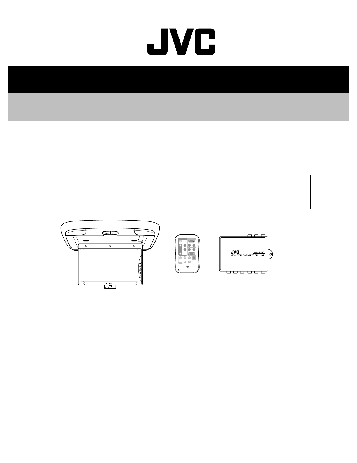
9-INCH WIDE COLOR MONITOR
KV-MR9000
Area Suffix
J -------------- Northern America
E ------------ Continental Europe
U --------------------- Other Areas
MONITOR
TV TUNER
T
V
C
H
SKI
P
MOD
E
A.MEM
O
VOCA
L
MENU
R F
H/P
VOLUM
E
CA
LL
VCP
RM-RK500
TABLE OF CONTENTS
1 PRECAUTION. . . . . . . . . . . . . . . . . . . . . . . . . . . . . . . . . . . . . . . . . . . . . . . . . . . . . . . . . . . . . . . . . . . . . . . . . 1-3
2 SPECIFIC SERVICE INSTRUCTIONS. . . . . . . . . . . . . . . . . . . . . . . . . . . . . . . . . . . . . . . . . . . . . . . . . . . . . . 1-4
3 DISASSEMBLY . . . . . . . . . . . . . . . . . . . . . . . . . . . . . . . . . . . . . . . . . . . . . . . . . . . . . . . . . . . . . . . . . . . . . . . 1-5
4 ADJUSTMENT . . . . . . . . . . . . . . . . . . . . . . . . . . . . . . . . . . . . . . . . . . . . . . . . . . . . . . . . . . . . . . . . . . . . . . . 1-13
5 TROUBLESHOOTING . . . . . . . . . . . . . . . . . . . . . . . . . . . . . . . . . . . . . . . . . . . . . . . . . . . . . . . . . . . . . . . . . 1-14
COPYRIGHT © 2003 VICTOR COMPANY OF JAPAN, LIMITED
No.49785
2003/11
Page 2
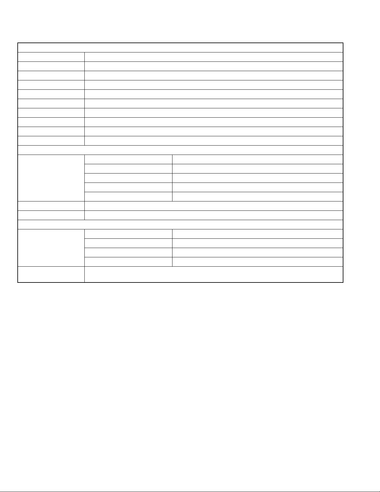
SPECIFICATION
WIDE COLOR MONITOR
Display 9 inch Liquid crystal panel
Number of Pixel 336,960 pixels (480 vertical × 234 horizontal × 3)
Drive Method TFT (Thin Film Transistor) active matrix format
Cordless Audio Infrared audio transmitter (Support IR receiver stereo headphones)
L-channel 2.3 MHz
R-channel 2.8 MHz
Effective listening angle 30°
Effective range 4 m (13.1 ft)
Dimensions (W × H × D) 314mm × 38mm × 257mm (12-3/8" × 1-1/2" × 10-1/8") including Shroud
Mass 1.2 kg (2.7 lbs) including Shroud
MONITOR CONNECTION UNIT
Input Video RCA pin × 2 circuits 1 V(p-p), 75 Ω Audio RCA pin × 2 circuits 0.5 V(rms)
Tuner 8-pin DIN connector (only for JVC's KV-C10) Output
Display 13-pin DIN connector
Video RCA pin × 1 circuit 1 V(p-p), 75 Ω
Audio RCA pin × 1 circuit 1 0.5 V(rms)
Dimensions (W × H × D) 108.5mm × 28.5mm × 78mm (4-5/16" × 1-1/8" × 3-1/8") excluding projections
Mass 160 g (0.36 lbs)
GENERAL
Power Requirement Operating Voltage DC 14.4 V (11 V to 16 V allowance)
Grounding System Negative ground
Allowable Operating Temperature 0°C to +40°C (32°F to 104°F)
Allowable Storage Temperature -20°C to +80°C (-4°F to 176°F) Ceiling light bulb12V/3W
ACCESSORIES Metal plate × 1, Shroud × 1, Extension cord × 1, Power cord × 1, Ceiling light cord × 1, Remote
controller(with the battery) × 1, Screw(M4 × 5mm)(M4 × 1/4") × 4, Screw(M4 × 12mm)(M4 × 1/2") × 4
Design and specifications are subject to change without notice.
The liquid crystal panel is built with very high precision technology and h as at least 99.99% precision techn ology and has a t least
99.99% effective image pixels. Be aware that on 0.01% of the panel there may be missing pixels or constantly lit pixels.
1-2 (No.49785)
Page 3
1.1 Safety Precautions
SECTION 1
PRECAUTION
!
Burrs formed during molding may be left over on some parts of the chassis. Therefore,
pay attention to such burrs in the case of preforming repair of this system.
(No.49785)1-3
Page 4

SECTION 2
SPECIFIC SERVICE INSTRUCTIONS
This service manual does not describe SPECIFIC SERVICE INSTRUCTIONS.
1-4 (No.49785)
Page 5
SECTION 3
DISASSEMBLY
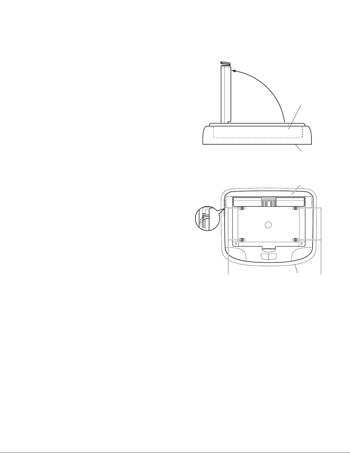
3.1 Base cover section
3.1.1 Removing the base cover aseembly
(See Figs.1 to 2)
(1) Move the monitor unit in the direction arrow.
(2) Remove the four screws A attaching the base cover as-
sembly.
REFERENCE:
Reassembly of the base cover aseembly
Before attaching the base cover, put the cable through the hole
a of the shroud. (See Fig.2)
Monitor unit
Shroud
Fig.1
Base cover
assmbly
Hole
a
Shroud
AA
Fig.2
(No.49785)1-5
Page 6

3.1.2 Removing the monitor unit
(See Figs.3 to 5)
• Prior to performing the following procedure, remove the base
cover aseembly.
(1) Release the four claws b attaching the shaft cover.
(2) Remove the four screws B attaching the hinge on the base
cover aseembly.
(3) Remove the two screws C attaching the conne ct bo ard on
the back of the base cover aseembly.
(4) Disconnect the two connectors B1
board.
REFERENCE:
Reassembly of the monitor unit section
Before attaching the monitor unit, put the flexible wire through
the hole c of the base cover aseembly. (See Fig.3)
and B2 on the connect
Hole c
Cover shaftCover shaft
Claw b Claw b
3.1.3 Removing the connect board
(See Fig.5)
• Prior to performing the following procedure, remove the base
cover aseembly.
(1) Remove the two screws C attaching the conne ct bo ard on
the base cover aseembly.
(2) Disconnect the two connectors B1
on the connect board.
, B2, CON1 and CON2
Connect board
Base cover assembly
Fig.3
BB
Fig.4
CON1
B1
B2
CON2
C
Fig.5
1-6 (No.49785)
Page 7

3.1.4 Removing the lamp control board
A
(See Fig.6)
• Prior to performing the following procedure, remove the base
cover aseembly.
(1) Disconnect the three connectors B3
lamp control board.
(2) Remove the three screws D attaching the lamp control
board on the base cover aseembly.
3.1.5 Removing the lamp bulb(L) and lamp bulb(R) bo ard
(See Figs.7 to 8)
• Prior to performing the following procedure, remove the base
cover aseembly.
(1) Remove the two screws E and four screws F attaching the
acryl covers(L) and (R) on the back of the base cover
aseembly.
(2) Disconnect the two connectors B3
trol board.
(3) Remove the lamp bulb board(L) and lamp bulb board(R) in
the direction arrow.
, B4 and B6 on the
and B4 on the lamp con-
cryl cover (R)
E
F
D
B6B4 B3
Lamp control board
B4 B3
Lamp control board
Fig.6
Fig.7
Acryl cover (L)
E
F
Lamp bulb
board (R)
Lamp bulb
board (L)
Fig.8
(No.49785)1-7
Page 8

3.1.6 Removing the cable assembly
(See Fig.9)
• Prior to performing the following procedure, remove the base
cover aseembly.
(1) Remove the two screws G attaching the connect board on
the back of the base cover aseembly.
(2) Remove the screw H and screw J attaching the wire brack-
et and wire fixer on the base cover aseembly.
(3) Disconnect the two connectors CON1
connect board.
(4) Disconnect the conne ctor B6
(5) Remove the cable attaching the wire bracket and wrire fixer
on the base cover aseembly.
on the lamp control board.
and CON2 on the
Lamp control boardB6
CON1
CON2
3.1.7 Removing the lamp bulb
(See Figs.10 to 11)
• Prior to performing the following procedure, remove the base
cover assembly.
(1) Release the two claws d attaching the lamp cover(L) and
lamp cover (R), remove the base cover aseembly.
(2) Remove the lamp bulb attaching the lamp holder.
HJ G
Wire bracketwire fixer
Fig.9
Lamp cover (L)
Claw d Claw d
Shroud Shroud
Fig.10
Lamp cover (R)
Code holder
Connect board
1-8 (No.49785)
LampLamp
Lamp holderLamp holder
Fig.11
Page 9

3.2 Shroud section
3.2.1 Removing the metal plate
(See Fig.12)
(1) Remove the four screws K attaching the metal plate on the
shroud.
KK
ShroudMetal plate
Fig.12
(No.49785)1-9
Page 10

3.3 Monitor unit seciton
r
r
3.3.1 Removing the bottom cover
(See Fig.13 to 16)
(1) Remove the three rubbers e attaching the top cover.
(2) Remove the three screws L attaching the top cover on the
bottom cover.
(3) Remove the four screws M and screw N attaching the bot-
tom cover.
(4) Release the bottom cover in the direction arrow.
Top cove
Rubber eRubber e
Fig.13
Top cove
M
Fig.14
N
Fig.15
LL
Bottom cover
M
Bottom cover
1-10 (No.49785)
Top cover
Fig.16
Page 11

3.3.2 Removing the monitor board
r
(See Fig.17)
• Prior to performing the following procedure, remove the bottom
cover.
(1) Disconnect the connectors B1
itor board.
(2) Disconnect the connector M1
board.
(3) Remove the solder from the ground wi re f on the back of
panel.
(4) Remove the four screws P attaching the monitor board.
, B2 and CON2 on the mon-
, B3 and W1 on the monitor
M1 B3CON2
B1
B2
Monitor boardTap e g
W1
3.3.3 Removing the panel
(See Fig.18)
• Prior to performing the following procedure, remove the bottom
cover.
(1) Remove the three screws Q atta ching the lcd bracket on
the top coverr.
(2) Remove the screw R attaching the panel.
(3) Remove the two screws S attaching the lcd bracket on the
top cover.
(4) Release the PC shield plate from flexible wire h, flexible
wire j.
CAUTION:
Be careful when release the PC shield plate do not damage
flexible wires.(See Fig. 18 )
3.3.4 Removing the mico switch bracket
(See Fig.19)
• Prior to performing the following procedure, remove the bottom
cover.
(1) Disconnect the connector W1
(2) Remove the two screws T attaching the mico switch brack-
et on the top cover.
on the monitor board.
LCD
bracket
Panel
R
Fig.17
Flexible wire h
Flexible wire j
Fig.18
Ground wire f
PC shield plate
LCD bracket
PP
Q
S
Monito
board
W1
T
Fig.19
Mico switch bracket
(No.49785)1-11
Page 12

3.4 Monitor connection box section
3.4.1 Monitor connection box
(Figs.20 to 21)
(1) Remove the screws A attaching the monitor connectoin
box.
(2) Release the bottom cover in the direction arrow.
A
Fig.20
Fig.21
1-12 (No.49785)
Page 13

SECTION 4
ADJUSTMENT
This service manual does not describe ADJUSTMENT.
(No.49785)1-13
Page 14

SECTION 5
TROUBLESHOOTING
This service manual does not describe TROUBLESHOOTING.
1-14 (No.49785)
Page 15

(No.49785)1-15
Page 16

VICTOR COMPANY OF JAPAN, LIMITED
AV & MULTIMEDIA COMPANY MOBILE ENTERTAINMENT CATEGORY 10-1,1chome,Ohwatari-machi,Maebashi-city,371-8543,Japan
(No.49785)
Printed in Japan
WPC
 Loading...