

Page 1
49785200311
SERVICE MANUAL
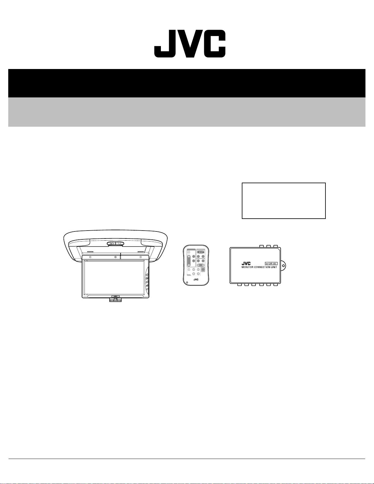
9-INCH WIDE COLOR MONITOR
KV-MR9000
Area Suffix
J -------------- Northern America
E ------------ Continental Europe
U --------------------- Other Areas
MONITOR
TV TUNER
T
V
C
H
SKI
P
MOD
E
A.MEM
O
VOCA
L
MENU
R F
H/P
VOLUM
E
CA
LL
VCP
RM-RK500
TABLE OF CONTENTS
1 PRECAUTION. . . . . . . . . . . . . . . . . . . . . . . . . . . . . . . . . . . . . . . . . . . . . . . . . . . . . . . . . . . . . . . . . . . . . . . . . 1-3
2 SPECIFIC SERVICE INSTRUCTIONS. . . . . . . . . . . . . . . . . . . . . . . . . . . . . . . . . . . . . . . . . . . . . . . . . . . . . . 1-4
3 DISASSEMBLY . . . . . . . . . . . . . . . . . . . . . . . . . . . . . . . . . . . . . . . . . . . . . . . . . . . . . . . . . . . . . . . . . . . . . . . 1-5
4 ADJUSTMENT . . . . . . . . . . . . . . . . . . . . . . . . . . . . . . . . . . . . . . . . . . . . . . . . . . . . . . . . . . . . . . . . . . . . . . . 1-13
5 TROUBLESHOOTING . . . . . . . . . . . . . . . . . . . . . . . . . . . . . . . . . . . . . . . . . . . . . . . . . . . . . . . . . . . . . . . . . 1-14
COPYRIGHT © 2003 VICTOR COMPANY OF JAPAN, LIMITED
No.49785
2003/11
Page 2
SPECIFICATION
WIDE COLOR MONITOR
Display 9 inch Liquid crystal panel
Number of Pixel 336,960 pixels (480 vertical × 234 horizontal × 3)
Drive Method TFT (Thin Film Transistor) active matrix format
Cordless Audio Infrared audio transmitter (Support IR receiver stereo headphones)
L-channel 2.3 MHz
R-channel 2.8 MHz
Effective listening angle 30°
Effective range 4 m (13.1 ft)
Dimensions (W × H × D) 314mm × 38mm × 257mm (12-3/8" × 1-1/2" × 10-1/8") including Shroud
Mass 1.2 kg (2.7 lbs) including Shroud
MONITOR CONNECTION UNIT
Input Video RCA pin × 2 circuits 1 V(p-p), 75 Ω Audio RCA pin × 2 circuits 0.5 V(rms)
Tuner 8-pin DIN connector (only for JVC's KV-C10) Output
Display 13-pin DIN connector
Video RCA pin × 1 circuit 1 V(p-p), 75 Ω
Audio RCA pin × 1 circuit 1 0.5 V(rms)
Dimensions (W × H × D) 108.5mm × 28.5mm × 78mm (4-5/16" × 1-1/8" × 3-1/8") excluding projections
Mass 160 g (0.36 lbs)
GENERAL
Power Requirement Operating Voltage DC 14.4 V (11 V to 16 V allowance)
Grounding System Negative ground
Allowable Operating Temperature 0°C to +40°C (32°F to 104°F)
Allowable Storage Temperature -20°C to +80°C (-4°F to 176°F) Ceiling light bulb12V/3W
ACCESSORIES Metal plate × 1, Shroud × 1, Extension cord × 1, Power cord × 1, Ceiling light cord × 1, Remote
controller(with the battery) × 1, Screw(M4 × 5mm)(M4 × 1/4") × 4, Screw(M4 × 12mm)(M4 × 1/2") × 4
Design and specifications are subject to change without notice.
The liquid crystal panel is built with very high precision technology and h as at least 99.99% precision techn ology and has a t least
99.99% effective image pixels. Be aware that on 0.01% of the panel there may be missing pixels or constantly lit pixels.
1-2 (No.49785)
Page 3

1.1 Safety Precautions
SECTION 1
PRECAUTION
!
Burrs formed during molding may be left over on some parts of the chassis. Therefore,
pay attention to such burrs in the case of preforming repair of this system.
(No.49785)1-3
Page 4

SECTION 2
SPECIFIC SERVICE INSTRUCTIONS
This service manual does not describe SPECIFIC SERVICE INSTRUCTIONS.
1-4 (No.49785)
Page 5
SECTION 3
DISASSEMBLY
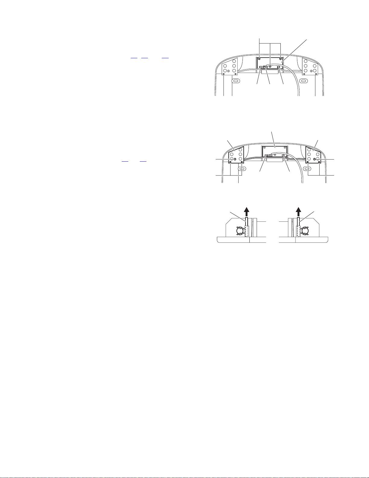
3.1 Base cover section
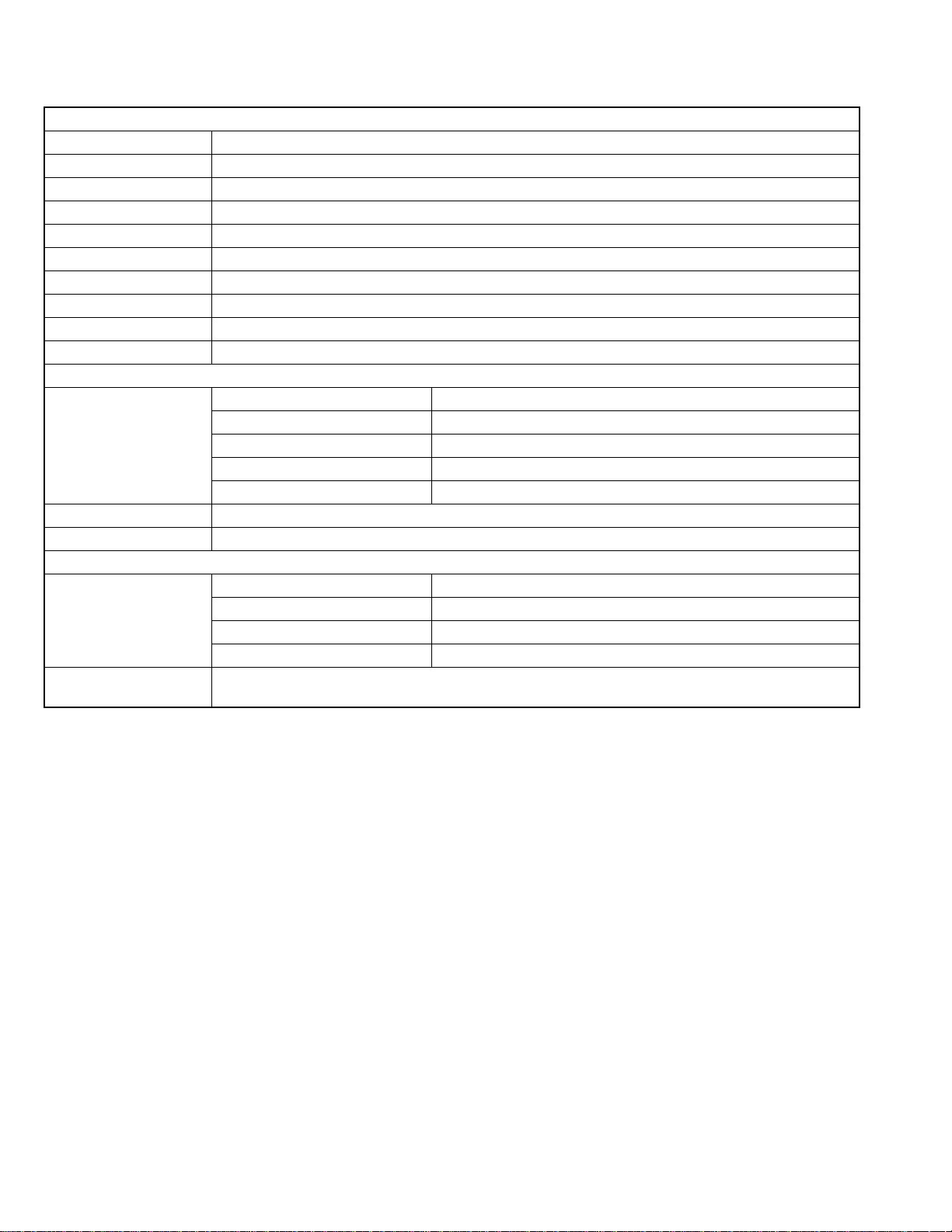
3.1.1 Removing the base cover aseembly
(See Figs.1 to 2)
(1) Move the monitor unit in the direction arrow.
(2) Remove the four screws A attaching the base cover as-
sembly.
REFERENCE:
Reassembly of the base cover aseembly
Before attaching the base cover, put the cable through the hole
a of the shroud. (See Fig.2)
Monitor unit
Shroud
Fig.1
Base cover
assmbly
Hole
a
Shroud
AA
Fig.2
(No.49785)1-5
Page 6
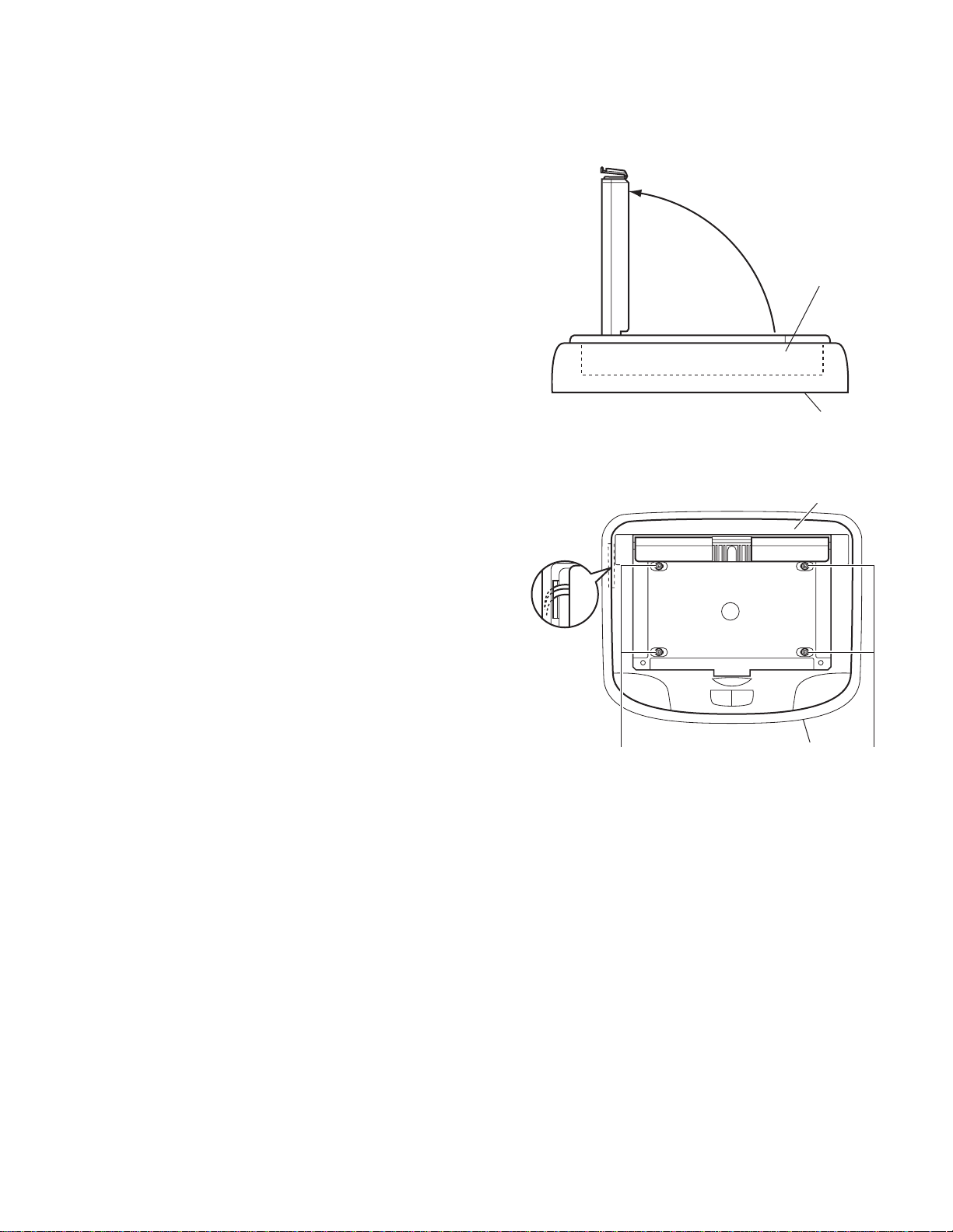
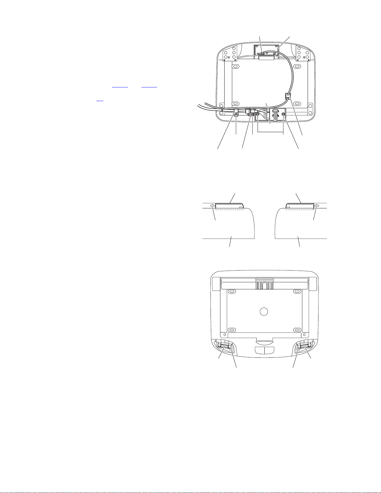
3.1.2 Removing the monitor unit
(See Figs.3 to 5)
• Prior to performing the following procedure, remove the base
cover aseembly.
(1) Release the four claws b attaching the shaft cover.
(2) Remove the four screws B attaching the hinge on the base
cover aseembly.
(3) Remove the two screws C attaching the conne ct bo ard on
the back of the base cover aseembly.
(4) Disconnect the two connectors B1
board.
REFERENCE:
Reassembly of the monitor unit section
Before attaching the monitor unit, put the flexible wire through
the hole c of the base cover aseembly. (See Fig.3)
and B2 on the connect
Hole c
Cover shaftCover shaft
Claw b Claw b
3.1.3 Removing the connect board
(See Fig.5)
• Prior to performing the following procedure, remove the base
cover aseembly.
(1) Remove the two screws C attaching the conne ct bo ard on
the base cover aseembly.
(2) Disconnect the two connectors B1
on the connect board.
, B2, CON1 and CON2
Connect board
Base cover assembly
Fig.3
BB
Fig.4
CON1
B1
B2
CON2
C
Fig.5
1-6 (No.49785)
Page 7
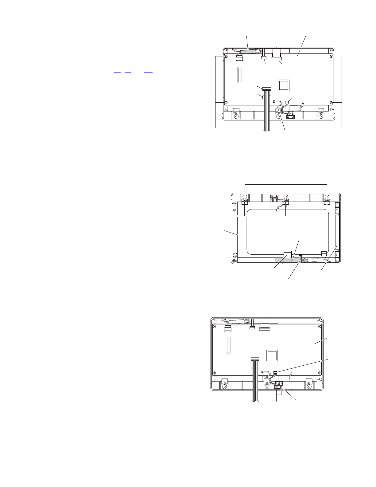
3.1.4 Removing the lamp control board
A
(See Fig.6)
• Prior to performing the following procedure, remove the base
cover aseembly.
(1) Disconnect the three connectors B3
lamp control board.
(2) Remove the three screws D attaching the lamp control
board on the base cover aseembly.
3.1.5 Removing the lamp bulb(L) and lamp bulb(R) bo ard
(See Figs.7 to 8)
• Prior to performing the following procedure, remove the base
cover aseembly.
(1) Remove the two screws E and four screws F attaching the
acryl covers(L) and (R) on the back of the base cover
aseembly.
(2) Disconnect the two connectors B3
trol board.
(3) Remove the lamp bulb board(L) and lamp bulb board(R) in
the direction arrow.
, B4 and B6 on the
and B4 on the lamp con-
cryl cover (R)
E
F
D
B6B4 B3
Lamp control board
B4 B3
Lamp control board
Fig.6
Fig.7
Acryl cover (L)
E
F
Lamp bulb
board (R)
Lamp bulb
board (L)
Fig.8
(No.49785)1-7
Page 8
3.1.6 Removing the cable assembly
(See Fig.9)
• Prior to performing the following procedure, remove the base
cover aseembly.
(1) Remove the two screws G attaching the connect board on
the back of the base cover aseembly.
(2) Remove the screw H and screw J attaching the wire brack-
et and wire fixer on the base cover aseembly.
(3) Disconnect the two connectors CON1
connect board.
(4) Disconnect the conne ctor B6
(5) Remove the cable attaching the wire bracket and wrire fixer
on the base cover aseembly.
on the lamp control board.
and CON2 on the
Lamp control boardB6
CON1
CON2
3.1.7 Removing the lamp bulb
(See Figs.10 to 11)
• Prior to performing the following procedure, remove the base
cover assembly.
(1) Release the two claws d attaching the lamp cover(L) and
lamp cover (R), remove the base cover aseembly.
(2) Remove the lamp bulb attaching the lamp holder.
HJ G
Wire bracketwire fixer
Fig.9
Lamp cover (L)
Claw d Claw d
Shroud Shroud
Fig.10
Lamp cover (R)
Code holder
Connect board
1-8 (No.49785)
LampLamp
Lamp holderLamp holder
Fig.11
Page 9
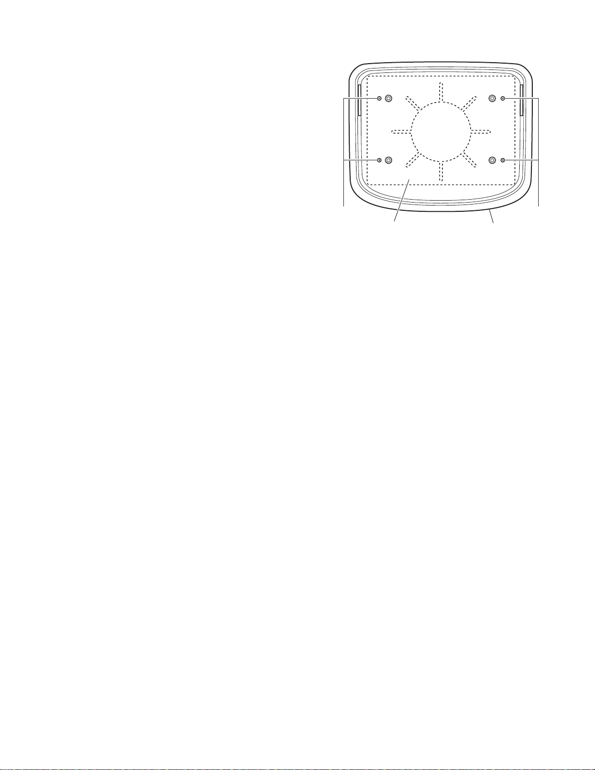
3.2 Shroud section
3.2.1 Removing the metal plate
(See Fig.12)
(1) Remove the four screws K attaching the metal plate on the
shroud.
KK
ShroudMetal plate
Fig.12
(No.49785)1-9
Page 10
3.3 Monitor unit seciton
r
r
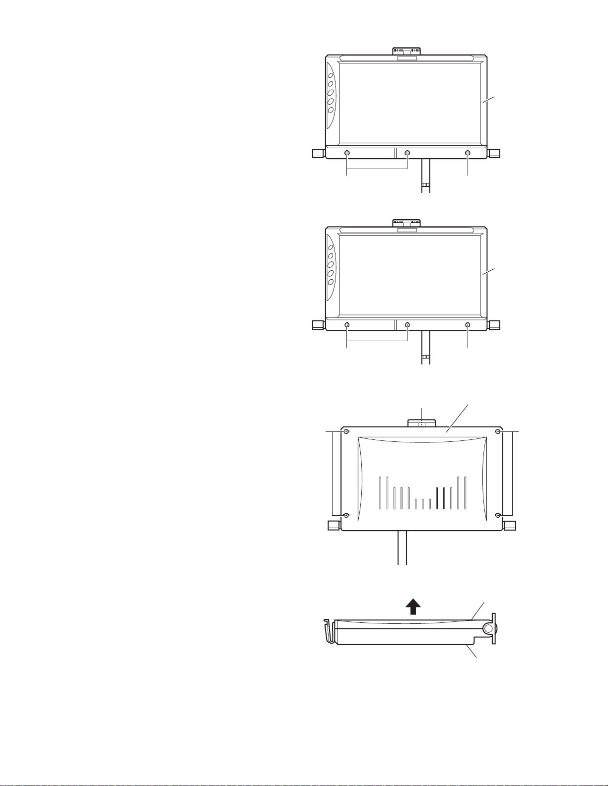
3.3.1 Removing the bottom cover
(See Fig.13 to 16)
(1) Remove the three rubbers e attaching the top cover.
(2) Remove the three screws L attaching the top cover on the
bottom cover.
(3) Remove the four screws M and screw N attaching the bot-
tom cover.
(4) Release the bottom cover in the direction arrow.
Top cove
Rubber eRubber e
Fig.13
Top cove
M
Fig.14
N
Fig.15
LL
Bottom cover
M
Bottom cover
1-10 (No.49785)
Top cover
Fig.16
Page 11
3.3.2 Removing the monitor board
r
(See Fig.17)
• Prior to performing the following procedure, remove the bottom
cover.
(1) Disconnect the connectors B1
itor board.
(2) Disconnect the connector M1
board.
(3) Remove the solder from the ground wi re f on the back of
panel.
(4) Remove the four screws P attaching the monitor board.
, B2 and CON2 on the mon-
, B3 and W1 on the monitor
M1 B3CON2
B1
B2
Monitor boardTap e g
W1
3.3.3 Removing the panel
(See Fig.18)
• Prior to performing the following procedure, remove the bottom
cover.
(1) Remove the three screws Q atta ching the lcd bracket on
the top coverr.
(2) Remove the screw R attaching the panel.
(3) Remove the two screws S attaching the lcd bracket on the
top cover.
(4) Release the PC shield plate from flexible wire h, flexible
wire j.
CAUTION:
Be careful when release the PC shield plate do not damage
flexible wires.(See Fig. 18 )
3.3.4 Removing the mico switch bracket
(See Fig.19)
• Prior to performing the following procedure, remove the bottom
cover.
(1) Disconnect the connector W1
(2) Remove the two screws T attaching the mico switch brack-
et on the top cover.
on the monitor board.
LCD
bracket
Panel
R
Fig.17
Flexible wire h
Flexible wire j
Fig.18
Ground wire f
PC shield plate
LCD bracket
PP
Q
S
Monito
board
W1
T
Fig.19
Mico switch bracket
(No.49785)1-11
Page 12
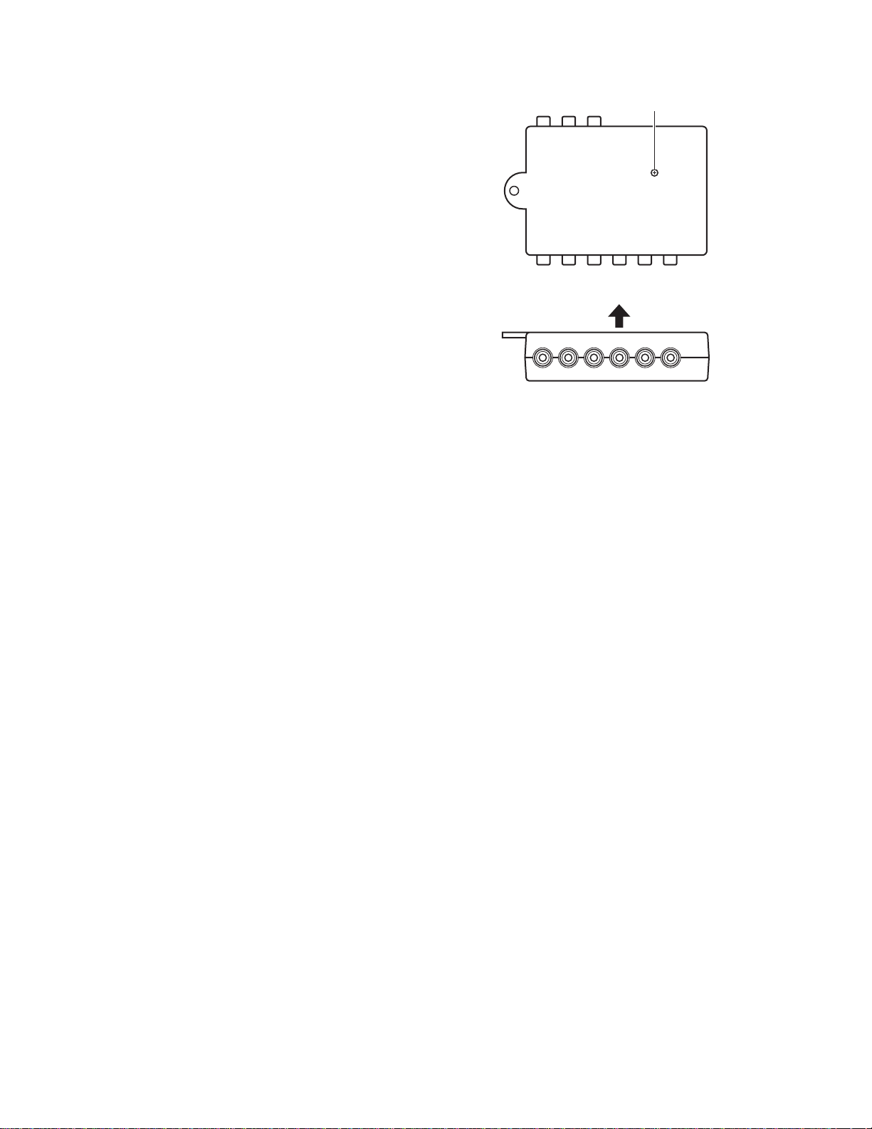
3.4 Monitor connection box section
3.4.1 Monitor connection box
(Figs.20 to 21)
(1) Remove the screws A attaching the monitor connectoin
box.
(2) Release the bottom cover in the direction arrow.
A
Fig.20
Fig.21
1-12 (No.49785)
Page 13

SECTION 4
ADJUSTMENT
This service manual does not describe ADJUSTMENT.
(No.49785)1-13
Page 14

SECTION 5
TROUBLESHOOTING
This service manual does not describe TROUBLESHOOTING.
1-14 (No.49785)
Page 15

(No.49785)1-15
Page 16

VICTOR COMPANY OF JAPAN, LIMITED
AV & MULTIMEDIA COMPANY MOBILE ENTERTAINMENT CATEGORY 10-1,1chome,Ohwatari-machi,Maebashi-city,371-8543,Japan
(No.49785)
Printed in Japan
WPC
Page 17

PARTS LIST
[ KV-MR9000 ]
* All printed circuit boards and its assemblies are not available as service parts.
Area suffix
E ----------- Continental Europe
J -------------- Northern America
U ---------------------- Other Areas
49785
- Contents -
Exploded view of general assembly and parts list (Block No.M1)
Electrical parts list (Block No.01~04)
Packing materials and accessories parts list (Block No.M3)
3- 2
3- 4
3-10
3-1
Page 18

Exploded view of general assmbly and parts list
6
18
16
17
15
14
Block No.
11
M
M
1
M
6
22
4
13
12
21
3
22
5
7
8
1
19
16
10
2
9
3-2
20
Page 19

General assembly
Block No. [M][1][M][M]
Symbol No.
1 CB-MR9000JEU MAIN PCB ASSY
2 CB-MR9000CON CONECT.PCB ASSY
3 CB-MR9000LAMP-L LAMP P.C.B.ASSY
4 CB-MR9000LAMP-R LAMP P.C.B.ASSY
5 CB-MR9000SW SWITCH PCB ASSY
6 MR9000-CLA CLUTCH ASSY (x2)
7 MR9000-LCD LCD.P.C.B.ASSY
8 MR9000-FPA FRONT PANEL ASSY
9 PU191070V01 FPC
10 PU191071V01 FPC
11 PUPL01012910 BUTTOM COVER
12 PUPL02002711 LAMP KEY
13 PUPL04001510 LAMP COVER L
14 PUPL04001610 LAMP COVER R
15 PUPL05002312 BASE COVER
16 PUPL10003914 COVER SHAFT (x2)
17 PU141690 CABLE
18 PU14116301 CONNECTOR WIRE
19 PUPL04005310 FLAT WIRE
20 PU311004 MICRO SW
21 PUPL02002812 DOOR KEY
22 PU312003 FUSE (x2)
Part No. Part Name Description Local
3-3
Page 20

Electrical parts list
Monitor board
Symbol No.
Q1 PU62KN3904S TRANSISTOR
Q2 PU622SC4672 TRANSISTOR
Q3 PU622SC4672 TRANSISTOR
Q4 PU622SD1048 TRANSISTOR
Q5 PU622SD1048 TRANSISTOR
Q6 PU622SC2712GR TRANSISTOR
Q7 PU622SC2712GR TRANSISTOR
Q8 PU622SA1797 TRANSISTOR
Q9 PU62KN3904S TRANSISTOR
Q11 PU62KN3906S TRANSISTOR
Q12 PU622SC2712GR TRANSISTOR
Q14 PU62KN3904S TRANSISTOR
Q15 PU62KN3904S TRANSISTOR
Q16 PU62KN3906S TRANSISTOR
Q17 PU62KN3904S TRANSISTOR
Q105 PU62KN3904S TRANSISTOR
Q106 PU62KN3904S TRANSISTOR
Q108 PU62KN3904S TRANSISTOR
Q301 PU62KTC2022 TRANSISTOR
Q414 PU622SA1182 TRANSISTOR
Q501 PU62DTC124EKA TRANSISTOR
Q502 PU62DTC124EKA TRANSISTOR
Q503 PU62DTC124EKA TRANSISTOR
Q510 PU622SA1797 TRANSISTOR
Q511 PU62KN3904S TRANSISTOR
Q604 PU622SC2412KR TRANSISTOR
Q610 AIC1732-33CX IC
Q660 PU622SA1037AKR TRANSISTOR
Q701 PU622SC2412KR TRANSISTOR
Q702 PU622SA1037AKR TRANSISTOR
Q703 PU62IMZ1A TRANSISTOR
Q770 PU622SA1037AKR TRANSISTOR
D1 PU6114Z12V0S Z DIODE
D2 PU6112Z6V8S Z DIODE
D3 PU6112Z5V6S Z DIODE
D4 PU6114Z7V5S Z DIODE
D6 PU611SS356 FR DIODE
D8 PU611SS356 FR DIODE
D9 PU6112Z6V8S Z DIODE
D10 PU61DA204UT1064 FR DIODE
D11 PU611SS356 FR DIODE
D12 PU6114Z7V5S Z DIODE
D13 PU6114Z7V5S Z DIODE
D301 PU61BAS16 FR DIODE
D302 PU61BAS16 FR DIODE
D303 PU61BAS16 FR DIODE
D304 PU61RB160L40 FR DIODE
D401 PU61DA204UT1064 FR DIODE
D408 PU61DA204UT1064 FR DIODE
D409 PU61DA204UT1064 FR DIODE
D410 PU61BAS16 FR DIODE
D412 PU61BAS16 FR DIODE
D413 PU61BAS16 FR DIODE
D701 PU611SS356 FR DIODE
D702 PU61MA338 FR DIODE
D703 PU611SS356 FR DIODE
D704 PU611SS356 FR DIODE
C1 PU175KW820J CHIP CAPACITOR
C2 PU175KW121J CHIP CAPACITOR
C3 PU175KW560J CHIP CAPACITOR
C4 PU175KW330J CHIP CAPACITOR
C5 PU175KW221J CHIP CAPACITOR
C6 PU175KW560J CHIP CAPACITOR
C7 PU175KW180J CHIP CAPACITOR
C8 PU175KW180J CHIP CAPACITOR
C9 PU175KW104Z CHIP CAPACITOR
C10 PU175KW104Z CHIP CAPACITOR
C11 PU175KW104Z CHIP CAPACITOR
C13 PU172.5BC476M E CAPACITOR
C14 PU175KW331J CHIP CAPACITOR
Part No. Part Name Description Local
Block No. [0][1][0][0]
Symbol No.
C15 PU175KW104Z CHIP CAPACITOR
C16 PU175KW331J CHIP CAPACITO R
C17 PU175KW104Z CHIP CAPACITOR
C18 PU171.6BC107M E CAPACITOR
C19 PU175KW680J CHIP CAPACITO R
C20 PU175KW471J CHIP CAPACITO R
C21 PU175KW680J CHIP CAPACITO R
C22 PU175KW471J CHIP CAPACITO R
C23 PU175KW102J CHIP CAPACITO R
C24 PU175KW102J CHIP CAPACITO R
C25 PU175KW104Z CHIP CAPACITOR
C26 PU175KW103K CHIP CAPACITOR
C27 PU175KW103K CHIP CAPACITOR
C28 PU175KW104Z CHIP CAPACITOR
C29 PU175KW104Z CHIP CAPACITOR
C30 PU172.5KZ106Z CHIP CAPACITOR
C31 PU175KW103K CHIP CAPACITOR
C32 PU175KW104Z CHIP CAPACITOR
C33 PU175KW102J CHIP CAPACITO R
C35 PU172.5BC476M E CAPACITOR
C36 PU172.5BC476M E CAPACITOR
C37 PU171.6KY225Z CHIP CAPACITOR
C38 PU175KW103K CHIP CAPACITOR
C39 PU175KW104Z CHIP CAPACITOR
C40 PU171.6KY225Z CHIP CAPACITOR
C41 PU175KW104Z CHIP CAPACITOR
C42 PU175KW104Z CHIP CAPACITOR
C43 PU171KW105Z CHIP CAPACITOR
C44 PU171KW105Z CHIP CAPACITOR
C45 PU171.6KW474Z CHIP CAPACITOR
C46 PU175KW104Z CHIP CAPACITOR
C47 PU175KW104Z CHIP CAPACITOR
C48 PU172.5BC476M E CAPACITOR
C49 PU172.5KZ106Z CHIP CAPACITOR
C51 PU175KW103K CHIP CAPACITOR
C52 PU175KW103K CHIP CAPACITOR
C53 PU172.5KY475Z CHIP CAPACITOR
C54 PU175KW104Z CHIP CAPACITOR
C55 PU171008 VOLTAGE CAP
C56 PU175KW104Z CHIP CAPACITOR
C57 PU175KW104Z CHIP CAPACITOR
C58 PU171LL228MH E CAPACITOR
C59 PU175KW104Z CHIP CAPACITOR
C60 PU171.6KY225Z CHIP CAPACITOR
C154 PU171.6BC107M E CAPACITOR
C200 PU172.5BC476M E CAPACITOR
C201 PU171.6KW474Z CHIP CAPACITOR
C202 PU171.6KW474Z CHIP CAPACITOR
C205 PU175KW471J CHIP CAPACITOR
C301 PU175KW471J CHIP CAPACITOR
C302 PU175KW471J CHIP CAPACITOR
C304 PU171.6KW474Z CHIP CAPACITOR
C305 PU175KW471J CHIP CAPACITOR
C306 PU175KW104Z CHIP CAPACITOR
C307 PU172.5BC476M E CAPACITOR
C309 PU172.5BC476M E CAPACITOR
C310 PU175KW104Z CHIP CAPACITOR
C311 PU172.5BC476M E CAPACITOR
C312 PU173.5BC226M E CAPACITOR
C313 PU175KW104Z CHIP CAPACITOR
C315 PU172.5BC476M E CAPACITOR
C316 PU175KW104Z CHIP CAPACITOR
C317 PU172.5BC476M E CAPACITOR
C318 PU172.5BC476M E CAPACITOR
C319 PU175KW104Z CHIP CAPACITOR
C320 PU172.5BC476M E CAPACITOR
C321 PU175KW102J CHIP CAPACITOR
C418 PU175KW102J CHIP CAPACITOR
C419 PU172.5KZ106Z CHIP CAPACITOR
C422 PU175KW102J CHIP CAPACITOR
C423 PU172.5KZ106Z CHIP CAPACITOR
C424 PU175KW102J CHIP CAPACITOR
C425 PU172.5KZ106Z CHIP CAPACITOR
C501 PU172.5KY475Z CHIP CAPACITOR
C502 PU175KW270J CHIP CAPACITOR
C503 PU175KW270J CHIP CAPACITOR
Part No. Part Name Description Local
3-4
Page 21

Symbol No.
Part No. Part Name Description Local
Symbol No.
Part No. Part Name Description Local
C504 PU171KW105Z CHIP CAPACITOR
C505 PU175KW104Z CHIP CAPACITOR
C506 PU172.5KZ106Z CHIP CAPACITOR
C508 PU175KW330J CHIP CAPACITOR
C509 PU175KW330J CHIP CAPACITOR
C510 PU175KW180J CHIP CAPACITOR
C511 PU175KW180J CHIP CAPACITOR
C513 PU171.6BC107M E CAPACITOR
C516 PU175KW104Z CHIP CAPACITOR
C517 PU175KW104Z CHIP CAPACITOR
C521 PU175KW103K CHIP CAPACITOR
C522 PU175KW103K CHIP CAPACITOR
C525 PU172.5KZ106Z CHIP CAPACITOR
C530 PU172.5KZ106Z CHIP CAPACITOR
C602 PU172.5KZ106Z CHIP CAPACITOR
C604 PU175KW104Z CHIP CAPACITOR
C605 PU171.6BC107M E CAPACITOR
C606 PU175KW104Z CHIP CAPACITOR
C607 PU175KW104Z CHIP CAPACITOR
C608 PU175KW104Z CHIP CAPACITOR
C609 PU175KW104Z CHIP CAPACITOR
C610 PU175KW104Z CHIP CAPACITOR
C611 PU175KW682K CHIP CAPACITOR
C612 PU171.6KY335Z CHIP CAPACITOR
C613 PU175KW103K CHIP CAPACITOR
C614 PU175KW122K CHIP CAPACITOR
C615 PU175KW103K CHIP CAPACITOR
C616 PU175KW103K CHIP CAPACITOR
C617 PU175KW103K CHIP CAPACITOR
C618 PU175KW103K CHIP CAPACITOR
C619 PU175KW103K CHIP CAPACITOR
C620 PU175KW473Z CHIP CAPACITOR
C621 PU175KW104Z CHIP CAPACITOR
C622 PU175KW103K CHIP CAPACITOR
C623 PU175KW103K CHIP CAPACITOR
C624 PU171KW105Z CHIP CAPACITOR
C625 PU171KW105Z CHIP CAPACITOR
C626 PU171KW105Z CHIP CAPACITOR
C627 PU171.6KW474Z CHIP CAPACITOR
C628 PU175KW103K CHIP CAPACITOR
C630 PU175KW103K CHIP CAPACITOR
C631 PU175KW104Z CHIP CAPACITOR
C632 PU175KW103K CHIP CAPACITOR
C633 PU172.5BC476M E CAPACITOR
C634 PU175KW103K CHIP CAPACITOR
C637 PU175KW104Z CHIP CAPACITOR
C638 PU175KW104Z CHIP CAPACITOR
C639 PU175KW121J CHIP CAPACITOR
C640 PU171.6BC107M E CAPACITOR
C641 PU171.6BC107M E CAPACITOR
C643 PU172.5BC476M E CAPACITOR
C663 PU175KW122K CHIP CAPACITOR
C664 PU175KW681J CHIP CAPACITOR
C665 PU175KW103K CHIP CAPACITOR
C666 PU175KW560J CHIP CAPACITOR
C667 PU175KW103K CHIP CAPACITOR
C668 PU175KW562K CHIP CAPACITOR
C669 PU175KW103K CHIP CAPACITOR
C701 PU172.5KZ106Z CHIP CAPACITOR
C702 PU172.5KZ106Z CHIP CAPACITOR
C703 PU175KW104Z CHIP CAPACITOR
C704 PU172.5BC476M E CAPACITOR
C705 PU175KW104Z CHIP CAPACITOR
C706 PU172.5KZ106Z CHIP CAPACITOR
C707 PU172.5KZ106Z CHIP CAPACITOR
C709 PU171.6KY225Z CHIP CAPACITOR
C710 PU175KW104Z CHIP CAPACITOR
C711 PU175KW104Z CHIP CAPACITOR
C712 PU175KW104Z CHIP CAPACITOR
C718 PU175KW104Z CHIP CAPACITOR
C719 PU171KW105Z CHIP CAPACITOR
C720 PU172.5KZ106Z CHIP CAPACITOR
C721 PU175KW102J CHIP CAPACITOR
C722 PU175KW104Z CHIP CAPACITOR
C723 PU175KW561J CHIP CAPACITOR
C725 PU175KW152K CHIP CAPACITOR
C726 PU175KW104Z CHIP CAPACITOR
C727 PU175KW121J CHIP CAPACITOR
C728 PU175KW104Z CHIP CAPACITOR
C729 PU175KW104Z CHIP CAPACITOR
C742 PU172.5KZ106Z CHIP CAPACITOR
C743 PU175KW104Z CHIP CAPACITOR
C744 PU175KW104Z CHIP CAPACITOR
C745 PU172.5KZ106Z CHIP CAPACITOR
C746 PU172.5KZ106Z CHIP CAPACITOR
C747 PU172.5KZ106Z CHIP CAPACITOR
C748 PU172.5KZ106Z CHIP CAPACITOR
C749 PU175KW104Z CHIP CAPACITOR
C750 PU175KW104Z CHIP CAPACITOR
C751 PU175KW104Z CHIP CAPACITOR
C752 PU175KW104Z CHIP CAPACITOR
C760 PU172.5KZ106Z CHIP CAPACITOR
C761 PU175KW122K CHIP CAPACITOR
C770 PU175KW122K CHIP CAPACITOR
R1 PU16110TW103J CHIP RESIS TOR
R2 PU16110TW470J CHIP RESIS TOR
R3 PU16110TW224J CHIP RESIS TOR
R4 PU16110TW0R0J CHIP RESISTOR
R5 PU16110TW302J CHIP RESIS TOR
R6 PU16110TW152J CHIP RESIS TOR
R7 PU16110TW0R0J CHIP RESISTOR
R8 PU16110TW101J CHIP RESIS TOR
R9 PU16110TW392J CHIP RESIS TOR
R10 PU16110TW303J CH IP RESIS TOR
R11 PU16110TW224J CH IP RE SISTOR
R12 PU16110TW0R0J CHIP RESISTOR
R14 PU16110TW182J CH IP RESIS TOR
R15 PU16110TW682J CH IP RESIS TOR
R16 PU16110TW682J CH IP RESIS TOR
R18 PU16110TW222J CH IP RESIS TOR
R19 PU16110TW222J CH IP RESIS TOR
R20 PU16110TW332J CH IP RESIS TOR
R21 PU16110TW272J CH IP RESIS TOR
R22 PU16110TW104J CH IP RESIS TOR
R23 PU16110TW101J CH IP RESIS TOR
R24 PU16110TW560J CH IP RESIS TOR
R25 PU16110TW332J CH IP RESIS TOR
R26 PU16110TW332J CH IP RESIS TOR
R27 PU16110TW183J CH IP RESIS TOR
R28 PU16110TW223J CH IP RESIS TOR
R30 PU16110TW103J CH IP RESIS TOR
R31 PU16110TW182J CH IP RESIS TOR
R32 PU16110TW332J CH IP RESIS TOR
R33 PU16110TW103J CH IP RESIS TOR
R34 PU16110TW0R0J CHIP RESISTOR
R35 PU16110TW153J CH IP RESIS TOR
R36 PU16110TW103J CH IP RESIS TOR
R37 PU16110TW101J CH IP RESIS TOR
R38 PU16110TW104J CH IP RESIS TOR
R39 PU16110TW101J CH IP RESIS TOR
R40 PU16110TW472J CH IP RESIS TOR
R41 PU16110TW472J CH IP RESIS TOR
R42 PU16110TW222J CH IP RESIS TOR
R43 PU16110TW3R3J CHIP RESISTOR
R44 PU16110TW473J CH IP RESIS TOR
R45 PU16110TW223J CH IP RESIS TOR
R46 PU16110TW333J CH IP RESIS TOR
R47 PU16110TW182J CH IP RESIS TOR
R48 PU16110TW473J CH IP RESIS TOR
R49 PU16110TW104J CH IP RESIS TOR
R50 PU16110TW243J CH IP RESIS TOR
R51 PU16110TW103J CH IP RESIS TOR
R52 PU16110TW104J CH IP RESIS TOR
R53 PU16110TW683J CH IP RESIS TOR
R54 PU16110TW223J CH IP RESIS TOR
R55 PU16110TW474J CH IP RESIS TOR
R56 PU16110TW124J CH IP RESIS TOR
R57 PU16110TW513J CH IP RESIS TOR
R58 PU16110TW824J CH IP RESIS TOR
R59 PU16110TW104J CH IP RESIS TOR
R61 PU16110TW394J CH IP RESIS TOR
R62 PU16110TW224J CH IP RESIS TOR
R63 PU16110TW243J CH IP RESIS TOR
R64 PU16110TW101J CH IP RESIS TOR
R67 PU16110TW103J CH IP RESIS TOR
3-5
Page 22

Symbol No.
Part No. Part Name Description Local
Symbol No.
Part No. Part Name Description Local
R68 PU16110TW681J CHIP RESISTOR
R69 PU16110TW223J CHIP RESISTOR
R70 PU16110TW223J CHIP RESISTOR
R71 PU16110TW824J CHIP RESISTOR
R72 PU16110TW681J CHIP RESISTOR
R73 PU16110TW332J CHIP RESISTOR
R74 PU16110TW332J CHIP RESISTOR
R75 PU16110TW0R0J CHIP RESISTOR
R76 PU16110TW122J CHIP RESISTOR
R78 PU16110TW223J CHIP RESISTOR
R79 PU16110TW473J CHIP RESISTOR
R80 PU16110TW0R0J CHIP RESISTOR
R81 PU16110TW153J CHIP RESISTOR
R82 PU16110TW820J CHIP RESISTOR
R83 PU16110TW333J CHIP RESISTOR
R84 PU16110TW102J CHIP RESISTOR
R85 PU16110TW153J CHIP RESISTOR
R86 PU16110TW103J CHIP RESISTOR
R89 PU16110TW010J CHIP RESISTOR
R90 PU16110TW3R3J CHIP RESISTOR
R92 PU16110TW0R0J CHIP RESISTOR
R92 PU16110TW3R3J CHIP RESISTOR
R93 PU16110TW3R3J CHIP RESISTOR
R94 PU16110TW393J CHIP RESISTOR
R95 PU16110NW103J CHIP THERMISTOR
R96 PU16110TW0R0J CHIP RESISTOR
R97 PU16110TW0R0J CHIP RESISTOR
R98 PU16110TW0R0J CHIP RESISTOR
R99 PU16110TW0R0J CHIP RESISTOR
R100 PU16110TW183J CHIP RESISTOR
R101 PU16110NW103J CHIP THERMISTOR
R104 PU16110TW104J CHIP RESISTOR
R123 PU16110TW104J CHIP RESISTOR
R124 PU16110TW101J CHIP RESISTOR
R127 PU16110TW473J CHIP RESISTOR
R130 PU16110TW562J CHIP RESISTOR
R131 PU16110TW104J CHIP RESISTOR
R135 PU16110TW333J CHIP RESISTOR
R201 PU16110TW393J CHIP RESISTOR
R202 PU16110TW393J CHIP RESISTOR
R203 PU16110TW224J CHIP RESISTOR
R214 PU16110TW183J CHIP RESISTOR
R215 PU16110TW333J CHIP RESISTOR
R216 PU16110TW102J CHIP RESISTOR
R301 PU16110TW393J CHIP RESISTOR
R302 PU16110TW393J CHIP RESISTOR
R303 PU16110TW332J CHIP RESISTOR
R305 PU16110TW333J CHIP RESISTOR
R306 PU16110TW333J CHIP RESISTOR
R307 PU16110TW242J CHIP RESISTOR
R308 PU16110TW122J CHIP RESISTOR
R309 PU16110TW513J CHIP RESISTOR
R310 PU16110TW153J CHIP RESISTOR
R313 PU16110TW183J CHIP RESISTOR
R314 PU16110TW333J CHIP RESISTOR
R316 PU16110TW221J CHIP RESISTOR
R437 PU16110TW102J CHIP RESISTOR
R438 PU16110TW331J CHIP RESISTOR
R439 PU16110TW221J CHIP RESISTOR
R440 PU16110TW471J CHIP RESISTOR
R441 PU16110TW101J CHIP RESISTOR
R445 PU16110TW101J CHIP RESISTOR
R446 PU16110TW473J CHIP RESISTOR
R447 PU16110TW103J CHIP RESISTOR
R448 PU16110TW223J CHIP RESISTOR
R453 PU16110TW243J CHIP RESISTOR
R454 PU16110TW823J CHIP RESISTOR
R455 PU16110TW153J CHIP RESISTOR
R456 PU16110TW101J CHIP RESISTOR
R457 PU16110TW473J CHIP RESISTOR
R458 PU16110TW223J CHIP RESISTOR
R459 PU16110TW433J CHIP RESISTOR
R460 PU16110TW101J CHIP RESISTOR
R461 PU16110TW182J CHIP RESISTOR
R4A1 PU1618TX201J CHIP RESISTOR
R4B1 PU1618TX201J CHIP RESISTOR
R4C1 PU1618TX201J CHIP RESISTOR
R4D1 PU1618TX201J CHIP RESISTOR
R4D2 PU1618TX201J CHIP RESISTOR
R501 PU16110TW104J CHIP RESISTOR
R502 PU16110TW102J CHIP RESISTOR
R503 PU16110TW104J CHIP RESISTOR
R504 PU16110TW102J CHIP RESISTOR
R505 PU16110TW102J CHIP RESISTOR
R506 PU16110TW102J CHIP RESISTOR
R507 PU16110TW105J CHIP RESISTOR
R508 PU16110TW101J CHIP RESISTOR
R509 PU16110TW104J CHIP RESISTOR
R510 PU16110TW103J CHIP RESISTOR
R511 PU16110TW103J CHIP RESISTOR
R513 PU16110TW104J CHIP RESISTOR
R517 PU16110TW102J CHIP RESISTOR
R519 PU16110TW101J CHIP RESISTOR
R520 PU16110TW101J CHIP RESISTOR
R521 PU16110TW101J CHIP RESISTOR
R525 PU16110TW103J CHIP RESISTOR
R526 PU16110TW101J CHIP RESISTOR
R528 PU16110TW104J CHIP RESISTOR
R535 PU16110TW103J CHIP RESISTOR
R536 PU16110TW103J CHIP RESISTOR
R539 PU16110TW103J CHIP RESISTOR
R550 PU16110TW473J CHIP RESISTOR
R551 PU16110TW473J CHIP RESISTOR
R553 PU16110TW223J CHIP RESISTOR
R561 PU16110TW473J CHIP RESISTOR
R608 PU16110TW750J CHIP RESISTOR
R609 PU16110TW750J CHIP RESISTOR
R610 PU16110TW750J CHIP RESISTOR
R612 PU16110TW121J CHIP RESISTOR
R613 PU16110TW153J CHIP RESISTOR
R614 PU16110TW153J CHIP RESISTOR
R615 PU16110TW183J CHIP RESISTOR
R616 PU16110TW105J CHIP RESISTOR
R617 PU16110TW474J CHIP RESISTOR
R618 PU16110TW153J CHIP RESISTOR
R619 PU16110TW153J CHIP RESISTOR
R620 PU16110TW102J CHIP RESISTOR
R621 PU16110TW102J CHIP RESISTOR
R622 PU16110TW334J CHIP RESISTOR
R623 PU16110TW101J CHIP RESISTOR
R624 PU16110TW102J CHIP RESISTOR
R625 PU16110TW684J CHIP RESISTOR
R626 PU16110TW101J CHIP RESISTOR
R627 PU16110TW102J CHIP RESISTOR
R628 PU16110TW563J CHIP RESISTOR
R629 PU16110TW393J CHIP RESISTOR
R630 PU16110TW563J CHIP RESISTOR
R631 PU16110TW393J CHIP RESISTOR
R632 PU16110TW565J CHIP RESISTOR
R633 PU16110TW103J CHIP RESISTOR
R634 PU16110TW103J CHIP RESISTOR
R635 PU16110TW562J CHIP RESISTOR
R636 PU16110TW101J CHIP RESISTOR
R637 PU16110TW101J CHIP RESISTOR
R638 PU16110TW101J CHIP RESISTOR
R640 PU16110TW103J CHIP RESISTOR
R641 PU16110TW102J CHIP RESISTOR
R642 PU16110TW562J CHIP RESISTOR
R643 PU16110TW183J CHIP RESISTOR
R644 PU16110TW153J CHIP RESISTOR
R645 PU16110TW393J CHIP RESISTOR
R646 PU16110TW183J CHIP RESISTOR
R651 PU16110TW562J CHIP RESISTOR
R653 PU16110TW103J CHIP RESISTOR
R654 PU16110TW103J CHIP RESISTOR
R655 PU16110TW123J CHIP RESISTOR
R656 PU16110TW123J CHIP RESISTOR
R660 PU16110TW102J CHIP RESISTOR
R661 PU16110TW910J CHIP RESISTOR
R662 PU16110TW471J CHIP RESISTOR
R663 PU16110TW331J CHIP RESISTOR
R665 PU16110TW106J CHIP RESISTOR
R666 PU16110TW562J CHIP RESISTOR
R667 PU16110TW152J CHIP RESISTOR
R669 PU16110TW562J CHIP RESISTOR
R701 PU16110TW101J CHIP RESISTOR
3-6
Page 23

Symbol No.
Part No. Part Name Description Local
Symbol No.
Part No. Part Name Description Local
R702 PU16110TW101J CHIP RESISTOR
R703 PU16110TW563J CHIP RESISTOR
R704 PU16110TW563J CHIP RESISTOR
R705 PU16110TW223J CHIP RESISTOR
R706 PU16110TW223J CHIP RESISTOR
R707 PU16110TW393J CHIP RESISTOR
R708 PU16110TW822J CHIP RESISTOR
R709 PU16110TW273J CHIP RESISTOR
R710 PU16110TW223J CHIP RESISTOR
R711 PU16110TW153J CHIP RESISTOR
R712 PU16110TW393J CHIP RESISTOR
R713 PU16110TW302J CHIP RESISTOR
R714 PU16110TW153J CHIP RESISTOR
R715 PU16110TW224J CHIP RESISTOR
R716 PU16110TW222J CHIP RESISTOR
R717 PU16110TW472J CHIP RESISTOR
R719 PU16110TW273J CHIP RESISTOR
R720 PU16110TW103J CHIP RESISTOR
R721 PU16110TW0R0J CHIP RESISTOR
R722 PU16110TW105J CHIP RESISTOR
R723 PU16110TW683J CHIP RESISTOR
R725 PU16110TW333J CHIP RESISTOR
R726 PU16110TW223J CHIP RESISTOR
R727 PU16110TW152J CHIP RESISTOR
R728 PU16110TW473J CHIP RESISTOR
R729 PU16110TW683J CHIP RESISTOR
R730 PU16110TW474J CHIP RESISTOR
R731 PU16110TW472J CHIP RESISTOR
R732 PU16110TW222J CHIP RESISTOR
R736 PU16110TW202J CHIP RESISTOR
R737 PU16110TW102J CHIP RESISTOR
R738 PU16110TW102J CHIP RESISTOR
R739 PU16110TW102J CHIP RESISTOR
R740 PU16110TW472J CHIP RESISTOR
R741 PU16110TW472J CHIP RESISTOR
R742 PU16110TW472J CHIP RESISTOR
R745 PU16110TW101J CHIP RESISTOR
R746 PU16110TW101J CHIP RESISTOR
R751 PU16110TW223J CHIP RESISTOR
R752 PU16110TW0R0J CHIP RESISTOR
R754 PU16110TW153J CHIP RESISTOR
R760 PU16110TW332J CHIP RESISTOR
R761 PU16110TW101J CHIP RESISTOR
R763 PU16110TW103J CHIP RESISTOR
R765 PU16110TW103J CHIP RESISTOR
R770 PU16110TW101J CHIP RESISTOR
R771 PU16110TW103J CHIP RESISTOR
R772 PU16110TW333J CHIP RESISTOR
R773 PU16110TW103J CHIP RESISTOR
R776 PU16110TW0R0J CHIP RESISTOR
R7A1 PU1618TX201J CHIP RESISTOR
R7B1 PU1618TX201J CHIP RESISTOR
R7C1 PU1618TX201J CHIP RESISTOR
R7D1 PU1618TX201J CHIP RESISTOR
R7D2 PU1618TX201J CHIP RESISTOR
R,668 PU16110TW331J CHIP RESISTOR
R556B PU16110TW332J CHIP RESISTOR
R556C PU16110TW332J CHIP RESISTOR
VR1 PU29R3S502 MVR32
VR2 PU29R3S502 MVR32
VR+5 PU29R3S502 MVR32
L1 PU291007220 COIL
L2 PU291007220 COIL
L4 PU291011 COIL
L200 PU291012 COIL
L301 PU291011 COIL
L302 PU291007330 COIL
L303 PU292002 TRANSFORMER
L304 PU291007330 COIL
L305 PU291011 COIL
L403 PU292021 TRANSFORMER
L501 PU291007150 COIL
L504 PU291007100 COIL
L600 PU291007100 COIL
L602 PU291007100 COIL
L661 PU291002 COIL SMD
L701 PU291007100 COIL
L702 PU291007100 COIL
L703 PU291007100 COIL
L704 PU291007100 COIL
L706 PU291007100 COIL
L707 PU291007012 COIL
L712 PU291007100 COIL
CON2 PU12100104 CONNECTOR
DN PU311041 TACT SWITCH
F1 PU32C1252K0FU FUSE SMD /TU
FB602 PU181009 FERRITE BEAD
FB606 PU181009 FERRITE BEAD
GASC PU16110TW0R0J CHIP RESISTOR
GAUD PU16110TW0R0J CHIP RESISTOR
GDC1 PU16110TW0R0J CHIP RESISTOR
GDC2 PU16110TW0R0J CHIP RESISTOR
GDC3 PU16110TW0R0J CHIP RESISTOR
GINV PU16110TW0R0J CHIP RESISTOR
GINV PU16110TW0R0J CHIP RESISTOR
GINV PU16110TW0R0J CHIP RESISTOR
GMCU PU16110TW0R0J CHIP RESISTOR
GMCU PU16110TW0R0J CHIP RESISTOR
GVID PU16110TW0R0J CHIP RESISTOR
GVID PU16110TW0R0J CHIP RESISTOR
IR PUOT06003710 RUBBER
M1 PU121013 WAFER
M2 PU611058 INFRARED
MENU PU311041 TACT SWITCH
MODE PU311041 TACT SWITCH
QM301 PU62IMZ1A TRANSISTOR
QM701 PU62IMX1 TRANSISTOR
U1 74HC4053D IC
U2 TC203G04AF IC
U3 TC4W53F IC
U4 HS9913ST IC
U5 PJ78L05A IC
U8 AP4532M IC
U9 AP4532M IC
U201 TL1451ACPWLE IC
U401 BIT3105 IC
U501 PIC16C77-04/L IC
U503 MB90097-PFV IC
U504 24LC02B IC
U506 M66242FP IC
U600 IR3Y29BM IC
U601 74HC4053D IC
U602 DG419DY IC
U701 LF353MX IC
U702 MN13821G IC
U704 LMC7101BIM5 IC
UP PU311041 TACT SWITCH
VBRI PU29R3S473 MVR32
VCDC PU29R3S473 MVR32
VCNT PU29R3S473 MVR32
VCOL PU29R3S473 MVR32
VCOM PU29R3S473 MVR32
VFREQ PU29R3S103 MVR32
VFRQ PU29R3S103 MVR32
VGA1 PU29R3S473 MVR32
VGA2 PU29R3S473 MVR32
VPIC PU29R3S473 MVR32
VRGB PU29R3S473 MVR32
VSUB PU29R3S473 MVR32
VSUR PU29R3S473 MVR32
VTIN PU29R3S473 MVR32
W702 PU16110TW0R0J CHIP RESISTOR
W703 PU16110TW0R0J CHIP RESISTOR
W705 PU16110TW0R0J CHIP RESISTOR
W706 PU16110TW0R0J CHIP RESISTOR
W710 PU16110TW0R0J CHIP RESISTOR
W711 PU16110TW0R0J CHIP RESISTOR
W719 PU16110TW0R0J CHIP RESISTOR
XXXXX PU192440V03 PCB
XXXXX PU6126410GT LED
XXXXX PU6126410GT LED
XXXXX PU6126410GT LED
XXXXX PU6126410GT LED
XXXXX PU121040 IC SOKET
3-7
Page 24

Connector board
Symbol No.
C1 PU175KW102J CHIP CAPACITOR
L1 PU181016 FERRITE BEAD
CON1 PU12101104 CONNECTOR
CON2 PU12101110 CONNECTOR
XXXXX PU192441V01 PCB
Part No. Part Name Description Local
Lamp Control board
Symbol No.
Part No. Part Name Description Local
Block No. [0][2][0][0]
Block No. [0][3][0][0]
Symbol No.
R182 PU16110TW104J CHIP RESISTOR
R186 PU16110TW223J CHIP RESISTOR
R187 PU16110TW473J CHIP RESISTOR
R190 PU16110TW103J CHIP RESISTOR
R191 PU16110TW103J CHIP RESISTOR
R192 PU16110TW220J CHIP RESISTOR
R222 PU16110TW104J CHIP RESISTOR
L1 PU291012 COIL
S1 PU311022 T ACT SWITCH
S2 PU311022 T ACT SWITCH
U18 PIC16C505 IC
XXXXX PU192443V02 PCB
XXXXX PU191072V03 PCB
XXXXX PU312003 TOSHIBA
XXXXX PU322007 HOLDER
XXXXX PU14116204 CONNECTOR
Part No. Part Name Description Local
Q1 PU62HMBT5551 TRANSISTOR
Q3 PU62KN3904S TRANSISTOR
Q4 PU62KN3904S TRANSISTOR
Q5 PU62KN3904S TRANSISTOR
Q6 PU62KN3904S TRANSISTOR
Q7 PU62IRF5410 TRANSISTOR
Q8 PU62KN3904S TRANSISTOR
Q9 PU62KN3904S TRANSISTOR
Q11 PU62KN3904S TRANSISTOR
Q12 PU62HMBT5551 TRANSISTOR
Q13 PU62KN3904S TRANSISTOR
D1 PU611SS356 FR DIODE
D2 PU6112Z5V6S Z DIODE
D3 PU61SS38 FR DIODE
D5 PU6114Z13V0S Z DIODE
D27 PU61SML010LTT86 LED
C1 PU171.6KZ106Z CHIP CAPACITOR
C2 PU171.6KZ106Z CHIP CAPACITOR
C3 PU171.6KZ106Z CHIP CAPACITOR
C4 PU171.6KZ106Z CHIP CAPACITOR
C5 PU172.5BC476M E CAPACITOR
C66 PU171.6KW104K CHIP CAPACITOR
C69 PU173.5BC106M E CAPACITOR
C71 PU175KW103K CHIP CAPACITOR
R1 PU16110TW223J CHIP RESISTOR
R2 PU16110TW223J CHIP RESISTOR
R3 PU16110TW223J CHIP RESISTOR
R4 PU16110TW220J CHIP RESISTOR
R5 PU16110TW223J CHIP RESISTOR
R6 PU16110TW473J CHIP RESISTOR
R7 PU16110TW223J CHIP RESISTOR
R9 PU16110TW104J CHIP RESISTOR
R10 PU16110TW104J CHIP RESISTOR
R11 PU16110TW472J CHIP RESISTOR
R12 PU16110TW472J CHIP RESISTOR
R13 PU16110TW0R0J CHIP RESISTOR
R16 PU16110TW104J CHIP RESISTOR
R22 PU16110TW220J CHIP RESISTOR
R23 PU16110TW473J CHIP RESISTOR
R24 PU16110TW223J CHIP RESISTOR
R25 PU16110TW103J CHIP RESISTOR
R26 PU16110TW104J CHIP RESISTOR
R27 PU16110TW472J CHIP RESISTOR
R28 PU16110TW104J CHIP RESISTOR
R29 PU16110TW682J CHIP RESISTOR
R30 PU16110TW123J CHIP RESISTOR
R31 PU16110TW222J CHIP RESISTOR
R34 PU16110TW472J CHIP RESISTOR
R35 PU16110TW104J CHIP RESISTOR
R36 PU16110TW104J CHIP RESISTOR
R44 PU16110TW224J CHIP RESISTOR
R113 PU16110TW223J CHIP RESISTOR
R180 PU16110TW223J CHIP RESISTOR
R181 PU16110TW103J CHIP RESISTOR
BOX board
Symbol No.
Q1 PU62KN3906S TRANSISTOR
Q2 PU62KN3906S TRANSISTOR
Q3 PU622SD1048 TRAN SISTOR
Q4 PU62KN3904S TRANSISTOR
Q5 PU62KN3904S TRANSISTOR
Q6 PU622SD1048 TRAN SISTOR
Q7 PU62KN3904S TRANSISTOR
Q8 PU62KN3904S TRANSISTOR
Q9 PU62KN3904S TRANSISTOR
Q10 PU62KN3906S TRANSISTOR
Q11 PU62KN3904S TRANSISTOR
Q12 PU62KN3904S TRANSISTOR
Q13 PU62KN3904S TRANSISTOR
Q14 PU622SA1797 TRANSISTOR
Q15 PU62KN3904S TRANSISTOR
Q16 PU62KN3906S TRANSISTOR
Q17 PU62KN3906S TRANSISTOR
Q101 PU62KN3904S TRANSISTOR
D1 PU611SS356 FR DIODE
D2 PU61SS38 FR DIODE
D3 PU611SS356 FR DIODE
D4 PU6114Z9V1S Z DIODE
D5 PU6114Z16V0S Z DIODE
D6 PU611SS356 FR DIODE
D8 PU6114Z9V1S Z DIODE
D9 PU611SS356 FR DIODE
D10 PU611SS356 FR DIODE
D11 PU611SS356 FR DIODE
D12 PU611SS356 FR DIODE
C1 PU171.6OY106M E CAPACITOR
C2 PU171.6OY106M E CAPACITOR
C3 PU172.5LL108M E CAPACITOR
C4 PU171.6OY225M TA SMD A +-20%
C5 PU172.5BC476M E CAPACITOR
C6 PU175KW104Z CHIP CAPACITOR
C7 PU171.6OY225M TA SMD A +-20%
C8 PU172.5KZ106Z CHIP CAPACITOR
C9 PU172.5KZ106Z CHIP CAPACITOR
C10 PU172.5KZ106Z CHIP CAPACITOR
C11 PU171.6OY106M E CAPACITOR
C12 PU171.6OY106M E CAPACITOR
C13 PU175KW104Z CHIP CAPACITOR
C14 PU171.6OY106M E CAPACITOR
C15 PU171.6OY106M E CAPACITOR
C16 PU171KZ226Z CHIP CAPACITOR
C17 PU175KW104Z CHIP CAPACITOR
C18 PU172.5KZ106Z CHIP CAPACITOR
C19 PU175KW103K CHIP CAPACITOR
Part No. Part Name Description Local
Block No. [0][4][0][0]
3-8
Page 25

Symbol No.
Part No. Part Name Description Local
Symbol No.
Part No. Part Name Description Local
C20 PU175KW104Z CHIP CAPACITOR
C21 PU171.6BC227M E CAPACITOR
C22 PU171.6BC227M E CAPACITOR
C23 PU172.5KZ106Z CHIP CAPACIT OR
C24 PU175KW104Z CHIP CAPACITOR
C25 PU175KW104Z CHIP CAPACITOR
C26 PU175KW104Z CHIP CAPACITOR
C27 PU172.5BC476M E CAPACITOR
C28 PU171.6OY105M TA SMD A +-20%
C29 PU171.6BC226M E CAPACITOR
C30 PU171.6OY106M E CAPACITOR
C31 PU171.6OY105M TA SMD A +-20%
C32 PU172.5KZ106Z CHIP CAPACIT OR
C33 PU175KW103K CHIP CAPACITOR
C34 PU175KW101J CHIP CAPA CITOR
C35 PU175KW101J CHIP CAPA CITOR
C36 PU1710PF103K MEI
C37 PU1710PF103K MEI
C45 PU172.5KZ106Z CHIP CAPACIT OR
C46 PU171.6OY106M E CAPACITOR
C47 PU171.6OY106M E CAPACITOR
C92 PU171.6OY106M E CAPACITOR
C101 PU172.5LL108M E CAPACITOR
C106 PU171.6BC107M E CAPACITOR
C123 PU175KW104Z CHIP CAPACITOR
R1 PU16110TW473J CHIP RESISTOR
R2 PU16110TW562J CHIP RESISTOR
R3 PU16110TW334J CHIP RESISTOR
R4 PU16110TW223J CHIP RESISTOR
R5 PU16110TW223J CHIP RESISTOR
R6 PU16110TW473J CHIP RESISTOR
R7 PU16110TW0R0J CHIP RESISTOR
R8 PU16110TW0R0J CHIP RESISTOR
R9 PU16110TW103J CHIP RESISTOR
R10 PU16110TW222J CHIP RESISTOR
R11 PU16110TW103J CHIP RESISTOR
R12 PU16110TW750J CHIP RESISTOR
R13 PU16110TW562J CHIP RESISTOR
R14 PU16110TW562J CHIP RESISTOR
R15 PU16110TW102J CHIP RESISTOR
R16 PU16110TW822J CHIP RESISTOR
R17 PU16110TW273J CHIP RESISTOR
R18 PU16110TW101J CHIP RESISTOR
R19 PU16110TW103J CHIP RESISTOR
R20 PU16110TW101J CHIP RESISTOR
R21 PU16110TW103J CHIP RESISTOR
R22 PU16110TW361J CHIP RESISTOR
R23 PU16110TW361J CHIP RESISTOR
R24 PU16110TW620J CHIP RESISTOR
R25 PU16110TW750J CHIP RESISTOR
R26 PU16110TW273J CHIP RESISTOR
R27 PU16110TW182J CHIP RESISTOR
R28 PU16110TW103J CHIP RESISTOR
R29 PU16110TW272J CHIP RESISTOR
R30 PU16110TW103J CHIP RESISTOR
R31 PU16110TW102J CHIP RESISTOR
R32 PU16110TW102J CHIP RESISTOR
R33 PU16110TW122J CHIP RESISTOR
R34 PU16110TW361J CHIP RESISTOR
R35 PU16110TW361J CHIP RESISTOR
R36 PU16110TW472J CHIP RESISTOR
R37 PU16110TW183J CHIP RESISTOR
R38 PU16110TW124J CHIP RESISTOR
R39 PU16110TW103J CHIP RESISTOR
R40 PU16110TW562J CHIP RESISTOR
R41 PU16110TW822J CHIP RESISTOR
R42 PU16110TW103J CHIP RESISTOR
R43 PU16110TW750J CHIP RESISTOR
R44 PU16110TW101J CHIP RESISTOR
R45 PU16110TW101J CHIP RESISTOR
R46 PU16110TW104J CHIP RESISTOR
R47 PU16110TW104J CHIP RESISTOR
R48 PU16110TW104J CHIP RESISTOR
R49 PU16110TW104J CHIP RESISTOR
R50 PU16110TW101J CHIP RESISTOR
R51 PU16110TW183J CHIP RESISTOR
R52 PU16110TW101J CHIP RESISTOR
R53 PU16110TW750J CHIP RESISTOR
R54 PU16110TW681J CHIP RESISTOR
R55 PU16110TW124J CHIP RESISTOR
R56 PU16110TW183J CHIP RESISTOR
R57 PU16110TW103J CHIP RESISTOR
R58 PU16110TW563J CHIP RESISTOR
R59 PU16110TW681J CHIP RESISTOR
R60 PU16110TW104J CHIP RESISTOR
R61 PU16110TW102J CHIP RESISTOR
R62 PU16110TW273J CHIP RESISTOR
R63 PU16110TW273J CHIP RESISTOR
R64 PU16110TW273J CHIP RESISTOR
R65 PU16110TW273J CHIP RESISTOR
R66 PU16110TW102J CHIP RESISTOR
R67 PU1614TY472J CHIP RESISTOR
R68 PU16110TW472J CHIP RESISTOR
R69 PU16110TW821J CHIP RESISTOR
R70 PU16110TW152J CHIP RESISTOR
R71 PU16110TW273J CHIP RESISTOR
R72 PU16110TW152J CHIP RESISTOR
R73 PU16110TW010J CHIP RESISTOR
R74 PU16110TW273J CHIP RESISTOR
R94 PU16110TW104J CHIP RESISTOR
R95 PU16110TW102J CHIP RESISTOR
R96 PU16110TW222J CHIP RESISTOR
R97 PU16110TW222J CHIP RESISTOR
R101 PU16110TW102J CHIP RESISTOR
R103 PU16110TW104J CHIP RESISTOR
L1 PU291090 COIL
L2 PU181016 FERRITE BEAD
J1 PUCN09LP4004 POWER WAFER
JIN1 PU122007 RCA JACK
JIN2 PU122007 RCA JACK
U1 NJM2521M IC
U3 NJM2246M IC
U4 NJM2521M IC
U6 BA4558F IC
U102 BA17808FP IC
XXXXX PU192445V02 PCB
3-9
Page 26

Packing materials and accessories parts list
J :A3,A9
U :A4,A5,A10,A11
E :A6,A7,A8,A12
A13,A14
Block No.
3
M
M
M
A2
A1
A19
A17
A18
A16
A15
3-10
Page 27

Packing and accessories
Block No. [M][3][M][M]
Symbol No.
A 1 PUPL08003315 MOUNTING SLEEVE
A 2 PUME03000911 BRACKET
A 3 LVT0986-001A INST (Jver) ENG SPA FRE
A 4 LVT0988-001A INST (Uver) ENG CHI THA ARA
A 5 LVT0988-002A INST (Uver) KOR
A 6 LVT0987-001A INST (Ever)
A 7 LVT0987-002A INST (Ever) SPA ITA POL RUS
A 8 LVT0987-003A INST (Ever)
A 9 LVT0986-002A INST SHEET J
A 10 LVT0988-003A INST SHEET U
A 11 LVT0988-004A INST SHEET U
A 12 LVT0987-004A INST SHEET E
A 13 LVT0987-005A INST SHEET E
A 14 LVT0987-006A INST SHEET E
A 15 PUKV90BOX CONNECTION UNIT
A 16 PU141611 DIN CORD
A 17 PU141164 DOM LIGHT WIRE
A 18 PU141942 POWER CORD
A 19 PURC9000 W.LESS REMOCON
Part No. Part Name Description Local
ENG GER FRE
DUT
SWE DAN FIN
GRE
3-11
Page 28

SCHEMATIC DIAGRAMS
9-INCH WIDE COLOR MONITOR
KV-MR9000
CD-ROM No.SML200311
Area Suffix
J -------------- Northern America
E ------------ Continental Europe
U --------------------- Other Areas
MONITOR
TV TUNER
T
V
C
H
SKI
P
MOD
E
A.MEM
O
VOCA
L
MENU
R F
H/P
VOLUM
E
CA
LL
VCP
RM-RK500
Contents
Block diagram
Standard schematic diagrams
Printed circuit boards
2-1
2-3
2-11 to 14
COPYRIGHT 2003 VICTOR COMPANY OF JAPAN, LTD.
No.49785SCH
2003/11
Page 29

Safety precaution
!
Burrs formed during molding may be left over on some parts of the chassis. Therefore,
pay attention to such burrs in the case of preforming repair of this system.
Page 30

< MEMO >
Page 31

C
Block diagram
W1
Monitor board
TO
Cable
TO
Cable
Connect board
CON1
AUD_L/R
ACC / CVBS_O
/ MUTE/ ON_DET
/ REM_SIG
CON2
/TUNER_DET
B+
MICRO SW
S1
B1
B2
B2
B1
REM_S
ACC
MUTE
ACC
Q105
Q108
A/B_SEL / TUNER_DET / ON_DET
POW_CTL
B+
MUTE_O
AUD_R
AUD_L
VR1 2.3MHz
VR2 2.8MHz
Q4
Q5
Q14
Q16
M2
REMOTE
CONTROL
SENSOR
U4
U5
Q414
Q15
U504
+12V_B
Q2
Q4
CON2
CVBS
REMOTE
ACC_DET
SCL / SDA
LED1-4
U501
MCU
TFT_ON / DIMMER
SIDE1 / JUST / ZOOM / VIDEO_DET
UC_MITPWM_CS
/ UC_MITPWM_WR
/ UC_MIT_SIN
/ UC_MIT_SCK
U506
X_SIN
/ X_SCK
/ OSD_CS
KEY0
NPC
Q9
Q501
-Q503
POW_CTL
U503
MENU / UP
DOWN / MODE
SW
COLOR / CONT
TINT / BRIGHT
HSYNC
/ VSYNC
/ OSD_R
/ OSD_G
/ OSD_B
/ SW
VTIN
TIN
VCOM
CVBS
TINT
NPC
TO
Power input
TO
Tuner box
Input1
Input2
Monitor connection board
BATT
J1
SW
TUNER_DET
/ON_DET
J2
CBST
/REM_S
CVBS1
JIN1
/A1L_IN
/A1R_IN
CVBS2
JIN2
/A2L_IN
/A2R_IN
Q14
ACC
U3
VIDEO
SW
U1/U4
AUDIO
SW
U102
+8V
REG
Q101
REM_S
A/B_SEL
IR led board
+8V
B+
POW_CTL
TUNER_DET
/ ON_DET
U6
AMP
CON4
LED1-8
CVBS_O
AL_O/AR_O
J3
TO
Monitor
JOUT2
Output
+12V_B / B+
2-1
Page 32

Q8/Q12
U401
POUT1
/ POUT2
/ NOUT1
/ NOUT2
U8
/ U9
M3
L403
VCOM
CVBS
TINT
NPC
COLORCTRL
Q6
Q7
OSD_R
/ OSD_G
/ OSD_B
/ SW
COM-AMP
CONT
VCNT
VID / TINTT
/ VCOIN / VCON
U1
/ VCOP
SYN_S
C_IN
TFT_ON
HSYNC / VSYNC /JUST / SIDE1 / ZOOM / VIDEO_DET
HSYNC
U600
BRIGHT
/ GAM1 / GAM2
/ RGB-AMP
/ PICTURE
CONTRAST
Q1
COLORCTRL
VCOL
/ WB/R /WB/B
VBRI / VGA1 / VGA2
/ VRGB / VPIC
/ WB/R / WB/B
POW_CTL
TINTT / VCOIN
SYNC_OUT
/ G_OUT
R-Y
/ B-Y
/C-MA
VCON / VCOP
Y1 / Y2
R_OUT
/ B_OUT
Q510
Q511
U601
Q660
COM-OUT / POL
DIMMER
CSYNC
RED / GREEN /BLUE
QM701
Q770
U602
SW.
U702
RESET
Q604
RESET
SYNCI
BLK
POL
NPC
VIN
COM-OUT
U2
R0
OP AMP
U701
U704
U3
VREQ
STH1 / STH2 / RL
CPH1 / CPV / OEH
/ STV1 / STV2
/ OEV1 / OEV2 / OEV3
Q701
-Q703
VCOM
VGH / VSS
VDD / U/D /VB
M1
LCD panel
B3
TO
Cable
Lamp control board
ACC_DET
B6
DOOR_SW
Q5
Q6
U201
REG
VFRQ
U18
Q301
/QM301
LAMP_ON
LAMP_DET
/ AUTO
Q1
Q7
F33007
TRANS.
LAMP_SW
AUTO_SW
Q8,Q11
/ Q3,Q9
VSS / VGH
VEE
+5V
VCC
+5V
Lamp bulb(R) board
B2
B4
B3
S1
S2
LAMP
B1
LAMP
Lamp bulb(L) board
2-2
Page 33

Standard schematic diagrams
25
GAMMA2
ACC FIL
12
O
A
_
G
R
Monitor section (1/2)
+5V
[1,2]
R22 100K
U506
M66242FP
1
2
3
4
5
6
7
100
R521
R520
R519
R38 100K
/CS
/R
/WR
SIN
SCLK
/OC
GND
10U
GND_MCU
10U
GND_MCU
DA204U
3
3
DA204U
R517 1K
10U
D409
D408
C425
R459
C419
C423
2
1
1
2
100
100
SW
U501
3
RA0/AN0
4
RA1/AN1
5
RA2/AN2
6
RA3/AN3/VR
7
RA4/TOCK
8
RA5/AN4
9
RE0/AN5
10
RE1/AN6
11
RE2/AN7
14
OSC1/CLKIN
15
OSC2/CLKOUT
2
MCLR
16
RC0/T1SO/T1CK1
18
RC1/T1S1/CCP2
19
RC2/CCP1
20
RC3/SCK/SCL
25
RC4/SDI/SDA
26
RC5/SD0
27
RC6/TX/CK
29
RC7/RX/DT
C522
0.01U
GND_MCU
14
VCC
13
PWM1
12
PWM2
11
PWM3
10
PWM4
9
XOUT
8
XIN
D413
BAS16
43K
BAS16
D410
22K
R448
15K
R455
B+_P
HSYNC
VSYNC
100
OSD_G
B12 [1]
Q17
3904
10U
27pC503
GND
GND
OSD_B [1]
C30
C517
R507
D412
BAS16
B49
[1,2]
B50
[2]
OSD_R [1]
B10 [1]
PIC16C77_PLCC
R1 10K
D3
5.6V
GND_MCU
0.1U
Y3
4M/22P
R458
22K
R447
10K
50K
RD7/PSP7
RD6/PSP6
RD5/PSP5
RD4/PSP4
RD3/PSP3
RD2/PSP2
RD1/PSP1
RD0/PSP0
1M
C525 10U
12
R316 220
REMOTE CONTROL SENSOR
100
[1]
R124
REM_S
Q105
3904
[1,2] B+
[1] A/B_SEL
[1] POW_CTL1
[2] AUD_R
[2] AUD_L
ACC
[1,2]
W2P_1.25
GND_MCU
VCC
B03
R125
[1,2] GND
MICRO_SW
U504
1
NC0
2
NC1
3
NC2
4
VSS
[1]
X_SCK
GND_P
3
(4.7K)
GND
[1] TUNER_DET
C40
C37
R30
10K
W1
1
2
24LC02BT
R551 47K
R550 47K
OSD_CS
[1]
R48 47K
[1]
X_SIN
GND_P
IRM-2038
R91
F1
B+_P
[1,2] ACC
[1] REM_S
[2] MUTE
[1,2] GND_VID
[1] CVBS
[1] ON_DET
2.2U
2.2U
0.1U
NCC
NC3
SCL
SDA
0.1U
C505
2
[1]
GND_P
8
7
6
5
D2
6.8V
R123
3904
Q108
GND_MCU
0
??
C28
GND
GND_MCU
DTC124EKA
Q501
GND_MCU
DTC124EKA
GND_MCU
1
M2
100K
AUDIOG
R31
1.8K
C516
0.1U
Q502
R513 100K
10K
R535
GND_MCU
R509 100K
47K
GND_MCU
10
9
8
7
6
5
4
3
2
1
B1
10
9
8
7
6
5
4
3
2
1
B2
4.7K
10K
R536
B04
VDD
C506
10U
[1]
REOTE
Q414
2SA1182
[1] POW_CNT
[2] DIMMER
[1] X_SCK
[1] X_SIN
SIDE1[2] B79
[1] OSD_CS
R127
JST10P_1.0DNJST10P_1.0DN
R41
GND
+5V
GND_MCU
GND_MCU
C12
??
[2]
[2] B08
JUST
ACC_DET
Q15
3904
GND
GND_MCU
R510
R511
C508
33P
KEY0
[1]
UC_MITPWM_CS
UC_MITPWM_WR
[1]
UC_MIT_SIN
[1]
[1]
UC_MIT_SCK
[1]
SCL [1]
SDA [1]
DTC124EKA
Q503
C504
1U
L501
15uH
R74
VIDEO_DET [1,2]B13
[1] ON_DET
[1] TUNER_DET
[1] ACC_DET
+5V
[1,2]
47K
R525
R561
R23
R503 100K
R505 1K
[1] TIN
COLORCTRL
[1] A08
COM-AMP
A10 [1]
GND_MCU
10K
10K
C509
33p
GND_MCU
3.3K
Y4
4MHz
C510
18P
10K
100R441
R526
100
R64
R506 1K
B03
U503
1
2
3
4
5
6
7
8
9
10
GND_MCU
GND_MCU
R501 100K
R504 1K
SCLK
/CS
SIN
/RST
VDD
SDR
XD
EXD
TEST
GND
MB90097
18P
C511
R539
10K
R508 100
100
100
B03
R502 1K
C501
4.7U
C424 1000P
1
1000P
2
C418
1
1000P
2
C422
GND_VID
[1] ON_DET
[1] TUNER_DET
/HSYNC
/VSYNC
VC0
VC1
VC2
BLKA
VC3
BLKB
TEST0
BLKC
R67 10K
R457
47K
R460
GND_VID
R445
GND_VID
R453
24K
20
19
18
17
16
15
14
13
12
11
GND_MCU
R446
47K
100
R456
100
GND_MCU
RB0/INT
C26
0.01U
R454
82K
R613VCOM
R614
RB7
RB6
RB5
RB4
RB3
RB2
RB1
NC1
NC2
NC3
NC4
VDD1
VDD2
VSS1
VSS2
GND_MCU
COLOR [1]
CONT
BRIGHT [1]
TINT [1]
27pC502
GND_MCU
TINT [1]
COLOR
15K
15K
44
43
42
41
39
38
37
36
33
32
31
30
24
23
22
21
1
40
28
17
35
12
34
13
GND_MCU
C530
10U
[1]
A10
COM-AMP
0.01U
C613
R8
L504
10U
[1,2] B03
R36
R39
R37
R73
R45
C513
[1,2] B01
[1,2] B02
[1,2] B03
[1,2] B06
[1] B10
[1] B11
[1] B12
[1]
BRIGHT
100K R528
B+_MCU
VID
R618
50K
VRGB
R619
100
[1]
R104
10K
100
100
3.3K
22K
100U/16V
[2]
2
15K
15K
100K
GND_MCU
C42
0.1U
[1]
POW_CNT
Q610
VI
GND
GND_VID
[1] CVBS
A04
RGB-AMP
R86 10K
1
R79 47K
GND_MCU
AME8805AEFT
3
VO
1
C643
47U/25V
OSD-G B10
R662
GND_VID
C615
0.01U
NPC [1,2]
SDA[1]
SCL[1]
UC_MITPWM_CS[1]
UC_MITPWM_WR[1]
UC_MIT_SIN [1]
UC_MIT_SIK [1]
REMOTE [1]
B07 [2]ZOOM
R54
22K
TFT_ON[2]
C44
MUTE_O[2]
AV1=A/B_SEL-HIGH
1U
+5V
[1,2]
4.7K
R40
32
Q9
3904
VGH B01
VEE B02
VCC B03
VDD
B04
VSS B06
OSD-B B11
SW B12
SW
COM-OUT
OSD-G
OSD-R
470
R663
1K
R620
50K
VPIC
1K
R621
A/B_SEL
POW_CTL
R78
22K
C43
1U
B[01:50]
B03
B12
B21
B10
330
A11
PICTURE
C616
0.01U
[1]
[1]
TP8
47U/25V
[1]
POW_CT
L600
10uH
R7
OSD_B
OSD_R [1]
R661 91
GND_VID
R87
??
R27 18K
R623
50K
VGA1
R624
C200
C59
0.1U
[1]
R608 75
GAM1
100
1K
C604
A05
TP1
R85 15K
GND_VID
0.1U
0
R609 75
C617
0.01U
C201
GND
100u/16v
R83 33K
C301
R301
39K
GND_VID
OSD-B
C663
R216
1K
R201
39K
470P
1
R610 75
C602 10U
L200
R203
0.01U
C521
220K
0.47U
16
15
RBP
SCP
C202
39K
R202
0.47U
C205
470P
14
13
IN+
IN2-
R215R214
33K
18K
GND
12
11
FB2
10
DTC2
OUT2
150uH(CD1
9
U201
VCC
TL1451AC
C1
RT
IN1+
IN1-
FB1
DTC1
OUT1
1
21
3
4
5
3
VFRQ
10K
2
3.3K
R303
GND
39K
R302
GND
C609
0.1U
C605
C641
100u/16v
32
Q7
C2712
GND_VID
R664 ?
1200P
GAM2
100
R626
50K
VGA2
1K
R627
100u/16v
GND_VID
GND_VID
3
Q6
1
C2712
2
C60 2.2U
R84 1K
C606 0.1U
0.1U
C607
0.1U
C608
0.1U
C610
R615
18K
C611
6800P
R616
1M
C612
3.3U
GND_VID
A06
C618
0.01U
WB/B
56K
R628
50K
VSUB
39K
R629
C302
470P
C640
R612
120
1200P
GND_VID
A02
C619
0.01U
R313
C304
0.47U
18K
VCC1
C58
R617
C614
A11 PICTURE
6
2200U/10V
GND_VID
470K
R665
A10 COM-AMP
R630
50K
VSUR
R631
GND
7
8
GND
33K
C305
R314
33K
R622
330K
COM_ADJ
COM_OUT
SW
B_IN
G_IN
R_IN
VCC1
F_ADJ
CLAMP
AGC_FILTER
AGC_OUT
PICTURE
50K
R305
R306
GND
B13
B49
POL B15
HSYNC
CSYNC
A[01:30]
[1]
WB/R A01
3635343332313029282726
FRP
SYN_S
SYNC_IN
COM_FRP
SYNC_OUT
SUB_BRIGHT_R
U600
IR3Y29BM
TAR P
CON
V_IN
IDFITER
C_IN
COLOR
123456789
A08 COLORCTRL
A09
CONTRAST
R633
10K
CONTRAST
CONTR
VCNT
Q1
3904
C623
10K
R634
0.01U
33K
VC
1
A03
WB/B A02
GAME1A05
RGB-AMP A04
BRIGHT
BRIGHT
GAMMA0
RGB_AMP
SUB_BRIGHT_B
BURST_OUT
KIL_FILTER
R-Y
B-Y
10
C620
0.047U
50K
30K
R10
GND
GAM2A06
11
R29
(470K)
470P
R660
1K
R625
680K
37
38
39
40
41
42
43
44
45
46
47
48
10M
C664
680P
A01
WB/R
56K
C622
0.01U
39K
2-3
Page 34

CONTRAST
CONTRAST
34
SYNC
OUT
CON
3
U201
R305
R306
L200
150uH(CD105)
33K
33K
GND
+12V_B
C306
0.1U
GND
R89
B+
[1,2]
Q510
2SA1797
[2]
R90
3.3
2.4K
R308
R307
QM301
6
1
C1
E1
5
2
B2
B1
4
3
E2
C2
IMZ1A
3.3K
R556B
Q511
3904
150uH(CD54)
1.2K
3.3K
R556C
L301
R76
R553
22K
GND
C307
47u/25v
GND
1.2K
1
R46
POW_CTL[1]
L303
GND_DC
GND
-10V
GND
6
KTC2022
D301
BAS16
12345
VIN
+5V
-15V
+7.5V
GND
GND
GND
PULSE
987
10
Q301
1000P
C321
82
R82
GND
F33007
DC/DC ER-11.5
RB160L-40
D304
D302
BAS16
D303
BAS16
47U/25V
C309
R309
R310
51K
VR+5
15K
GND_DC
C312
22U/35V
C315
47U/25V
C318
47U/25V
5K
VGH
VEE
VCC
VSS
VDD
L302
22UH
47U/25V
C310
0.1U
0.1U0.1U
C313
C316
150uH(CD54)
0.1U
C319
DC_VOL
C311
R760
3.3K
L304
22UH
C317
47U/25V
L305
C320
47U/25V
+17V
+7.5V
+5V
-10V
+3.3V
33K
C41
0.1U
GND
VGH
D1
GND_DC
B06
VSS
[1,2]
B01
1
[1,2]
12V
2
B02
VEE
[1,2]
B03
VCC
[1,2]
GND_DC[1,2]
B49
POL B15
HSYNC
A[01:30]
[1]
WB/B A02
WB/R A01
333231302928272625
FRP
_
SYNC_IN
COM_FRP
SUB_BRIGHT_B
SUB_BRIGHT_R
U600
IR3Y29BM
V_IN
IDFITER
C_IN
COLOR
BURST_OUT
45678
C620
0.047U
A08 COLORCTRL
CONTR
Q1
3904
C623
0.01U
VCO
1
A03
GAM2A06
GAME1A05
RGB-AMP A04
BRIGHT
BRIGHT
GAMMA0
RGB_AMP
G_DC_DET
R_DC_DET
KIL_FILTER
R-Y
B-Y
9
101112
R29
(470K)
50K
30K
R10
GND_VID
B_DC
GAMMA2
G_OUT
R_OUT
VCO_IN
APC_FIL
ACC_FIL
C_MA
R640
VCOL
R641
BOUT
VCC2
GND2
GND1
VCOIN
TINTT
[1]
C621
0.1U
TINT
5.6M R632
GND_VID
10K
1K
24
23
22
21
20
19
18
17
16
15
14
13
23uH
C626
R636
R637 100
R638
[1]
VCOIN
R635 5.6K
C665
0.01U
56P
C666
L661
A08A09
R643
COLORCTRL
VTIN
50K
C6280.01U
R644
A29
1U
100
18K
15K
TP4
100
C627
0.47U
A21
A22
C632
0.01U
C624 1U
C625
C630
R642
5.6K
[1] VCON
[1] VCOP
[1]
TIN
50K
C631
1U
0.01U
GND_VID
3.58M/16P
A03
BRIGHT
39K
R645
VBRI
2
13
C634
18K
R646
0.01U
47U/25V
C633
12K
C10
0.1U
GND_VID
G_V
G_VI
RED B16
GREEN B17
BLUE B18
BLK B22
POL B15
HD-OUT1 B14
POL B15
VDD B14
CVBS
GND_VID
B01 VGH
B02 VEE1
B03 VCC
B04 VDD
B06 VSS
B21 COM-OUT
B17 GREEN
B18 BLUE
B13 CSYNC
B16 RED
[1]
1
2
3
4
5
6
7
8
GND_VID
[1,2] NPC
L1
33P
56P
C6
GND_VID
TINTT [1]
VCON [1]
V1
V0
Z1
Z
Z0
INH
VEE
VSS
4053D
22UH
TINT [1]
VCOP [1]
U1
VDD
L2
22UH
B01 [1,2]
B02 [1,2]
B03 [1,2]
B04 [1,2]
B05 [1,2]
B21 [1,2]
B17 [1,2]
B18 [1,2]
B13 [1,2]
B16 [1,2]
C9
0.1U
VCC1
16
[1]
15
VCOIN
V
14
X
VID
13
X1
[1]
12
X0
11
A
10
B
9
C
C4
C3
56P
VEE1 B02
12K
R655
9101112131415
16
C11
0.1U
GND_VID
L602
10uH
0.1U
TP2
TP3
3K
R6
1.5K
R5
C8
C7
18p
18p
Y1
Y2
4.4M/16P
A07
A07
[1]
TINT
A08
[1]
A08
COLORCTRL
A09
[1]
A09
CONTRAST
A10
[1]
A10
COM-AMP
A22
A21
A29
[1]
A[01:30]
B
A
X
V
C
X0
X1
VDD
U601
1
R651
5.6K
VCC1
4053D
VSS
VEE
INHZ0ZZ1V0
V1
8765432
GND_ VID
10K
R653
GND_VID
R654
R668
330
R666
5.6K
C667
C669
10K
0.01U
0.01U
C637
0.1U
C638
0.1U
GND_VID
Q604
2SC2412KR
C639
R656
120P
[1,2] B15
[1,2] B14
876
5
U602
DG419DY
234
1
GND_VID
Q660
2SA1037AKR
R667
1.5K
R669
5.6K
5600P
C668
2-4
Page 35

Monitor section (2/2)
0
1
K
C
I
_
Q8
2SA1797
L4
R93
3.3
R92
3.3
[1,2]
B+
R43
3.3
C154
PA1
1
PAD
GND
47U/25V
GND_P
Q12
TFT_ON
[1]
AUDIO G
3904
GND_INV
GND_INV
0 G_INV0
0 G_INV1
0 G_INV2
0 G_DC1
0 G_DC2
0 G_DC3
0 G_MCU1
0 G_MCU2
0 G_ASC
0 G_VID0 G_AUD
GND
B+
[1,2]
[1]
+5V
[1]
KEY0
GND
R42
2.2K
D9
GND_P
R47 1.8K
R461
P
R135
R437
1K
6.8V
1.8K
ACC
150uH(CD54)
R44
47K
C48
3.3K R25
GND_INV
0.1U
C46
D4
0.1U
GND_INV
R62
220K
GND_INV
GND_DC
GND_MCU
GND_ASC
0 G_VID1
GND_VID
MUTE
Q16
3906
R52 100K
10K
GND
Q11
3906
56
100K
R28 22K
Q106
3904
5.6K R130
GND
R438
330
PT-004-E1
UP
LED2 LED3 LED4
47U/25V
7.5V
[1,2]
R51
3904
0.01U
3.3K R26
0.47U
C45
R61 390K
C39
R59 100K
DIMMER
[1]
[1,2]
+5V
100K R49
MUTE_0
[1]
R24
R131
33K
0.1U
C29
PT-004-E1
LED1
L-10GT L-10GT L-10GT L-10GT
R68 680
R57 51K
201918171615141312
SST
AVDD
DIMDC
CLAMP
CTPWM
PWMOUT
LOAD
RTDLY
OLP
AGND
CMP
INN
123456789
470KR55
C31
0.01U
24KR50
R56 120K
R53 68K
GND_INV
COM-OUT
ISS356 D11
Q14
[1,2] ZOOM
PT-004-E1
[1,2] JUST
[1,2] SIDE1
DN
MENU
B+_MCU
C27
GND
[1]
R439
220
EA
CTOSC
VEE1
[1,2] B02
[1,2] B04
[1,2] B03
[1,2] B06
[1,2] B21
[1,2] B16
GREEN
[1,2] B17
CSYNC
[1,2] B13
[1,2] B22
[1,2] B15
HD-OUT1
[1,2] B14
[1,2] RL
HYSNC
[1,2] B49
VYSNC
[1,2] B50
R440
470
VDD
VCC
VSS
RED
BLK
POL
0.1U C47
220P
C5
PVDD
PGND
B01
[1,2]
D13 7.5V
GND_INV
POUT2
NOUT2
VGH
B07
B08
B79
B20
PT-004-E1
+12V_B
[1,2]
0.01U
0.01U
C52
11
POUT1
NOUT1
10
GND_INV
GND_P
3
1
2
1
2
3
4
GND_A
10U
5
VSS
4
TX-18.5
VCDC
GND_A
2.2U
50K
D10
L403
39K R712
R72 680
GND_A
LF353MX
C710
0.1U
C709
C38
6
5
C711
0.1U
GND_ASC
0.01U
10P/3KV
C55
4
3
2
1
L706
10uH
R716
2.2K
10K
VFEQ
C718
0.1U
4.7K
R717
GND_ASC
1
OUT
U702
3
VDD
GND
MN13821
R63 24K
120P
C2
GND_ASC
R81
15K
R754
15K
B13
CSYNC
7.5V
C56
0.1U
C49
R69 22K
R70 22K
0.1U
D12
C51
BIT3105
U401
B01
VDD
B04
B02
B04
B03
B06
B21
SIDE1
B79
B16
JUST
B08
ZOOM
B07
B17
B13
B02 VEE1
L701
10uH
B22
B15
B14
COM-OUT
B21
B07
B08
B79
B20
VSS
B06
B49
B50
B69VCOM
MODE
??
C57
C50
10U/25V
0
0
0
R99
R34
R98
4
GND_INV
GND_A
10U
C760
GND_ASC
C701
10U
C702
L702
10uH
3
2
1
ao4600
4
3
2
1
ao4600
C54
0.1U
GND_A
L704
10uH
C703
R703 56K
0.1U
GND_ASC
10U
56K
R704
C705
C704
47u/25V
0.1U
GND_ASC
Q701
2SC2412KR
Q702
2SA1037AKR
C32
0.1U
U9
U8
C707
R701 100
R702 100
GND_A
5
6
7
8
5
6
7
8
R71 820K
L703
10uH
10U
R707
8.2K R708
IMZ1A
Q703
R33 10K
R58 820K
123
654
R705 22K
C53
4.7U/25V
C712
0.1U
GND_ASC
39K
R709 27K
R706 22K
D401
C706
GND_ASC
876
-
+
VCC
+
-
U701
123
GND_ASC
TP9
R710 22K
R751 22K
M3
M1
1
2
3
4
CM02B-BHSS-1TB
10U
C720
GND_ASC
ISS356
R75
2
R752
GND_ASC
R714
C770
1200P
[1]
AUD_L
[1]
AUD_R
10K
R720
D702
MA338
GND_ASC
W701
W702
W703
W704
W705
W706
W707
W708
W709
W710
D701
R719
0
0
0
??W712
NPC
[1]
W711
R715
220K15K
C761
1200P
R4
0
AUDIOG
R12
0
AUDIOG
C721
1000P
GND_ASC
[1,2]
MUTE
D6
ISS356
3.3K
R20
D8
ISS356
AU
2.7K
R21
AUDIOG
AUD
R722
1M
R723
C722
27K
C719
1U
15K R711
10K R771
QM701
6
5
4
68
0.1U
560PC723
??
0
0
?
0
0
??
33
34
??
35
36
??
37
38
0
39
40
41
42
43
44
45
46
47
48
GND_AS
33K R772
Q77
2SA
1
2
3
IMX1
2-5
Page 36

ISS356
[1,2]
MUTE
D6
ISS356
D8
AUDIOG
AUDIOG
AUDIOG
R18
2.2K
R96
0
R19
2.2K
Q5
D1048
AUDIOG
VR1
12
Q4
D1048
R97
1
0
VR2 5K
10KTH
R101
C15
3
0.1U
5K
10KTH
C17
0.1U
3
???
2.3MHZ
R95
2.8MHZ
U4
HS-9913-ST
20
1
C14
330P
R3
R17
220K
R11
220K
R13
???
R14
2
1.8K
R100
18K
2
3
R9
3.9K
4
R94
39K
5
6
C16
330P
7
8
10
AUDIOG
C13
19
47U/25V
18
17
16
15
14
C18
13
129
11
100U/16V
AUDIOG
U5
KIA78L05F
R2
1
47
3
1
2
0.1U
R4A1 200
2
C25
GND
TP7
2.3Mhz
C20
470P
C19
68P
123
CON2
1.0MM_4PDN
1
R15
6.8K
Q2
2SC4672
GND
2.8Mhz TP6
C21
68P
C22
AUDIOG
R4B1 200
4
R4C1 200
R16
6.8K
470P
1000P
R4D1 200
C23
R4D2 200
R7D2 200
Q3
2SC4672
GND
R7A1 200
C35
47U/25V
R7B1 200
121
GND
1000P
GND
R7C1 200
2
C24
R7D1 200
C36
47U/25V
+12V_B
[1,2]
L712
10uH
FULLNORMALCINEMAZOOM
CPH1 B51
CPH2 B04
CPH3 B04
10K B04
OEH B67
STV1 B71
STV2 B72
VDD B04
OEV1 B74
OEV2 B75
OEV3 B76
CPV
VB
RL B20
STH2
B[01:80]
B3
VCOM
B55
B63
B16
B17
B18
B67
0
W719
B04
W720
?
GND_ASC
B51
B20
B58
B69
VDD
B72
B76
B75
B74
B78
B19
B71
VSS
B06
[1,2]
B58
B01
[1,2]
B55
STH1
D704
B04
ISS356
D703
B04
ISS356
B03
B19
UD
B78
VCC
[1,2]
B04
B03
B63
VGH
VEE
VCC
VSS
VDD
C749
R32 3.3K
10U
C750
10U
+17V
+7.5V
+5V
-10V
+3.3V
GND_ASC
1
STH1
2
VB
3
RFD
4
GREEN
5
BLUE
6
OFH
7
VDD
8
MODE
9
CPH1
10
CPH2
11
CPH3
12
RL
13
STH2
14
+5V(VFF)
15
GND
16
VCOM
17
STV2
18
OFV3
19
OFV2
20
OFV1
21
CPV
22
U/D
23
STV1
24
NC
25
VSS1
26
GND_ASC
27
VDD
28
NC
29
VGH
30
30P_0.5
C748
10U
0.1U
C745
0.1U
C746
0.1UC751
10UC747
0.1UC752
GND_ASC
22K
UONS
SIDE2
SIDE1
Z.J/SEL
TC203G04AF-0011
VOUT
VDFIN
VDFOUT
VIN
0
R721
100R745
5
V-
JUST
U2
HYSNC
V+
ZOOM
HOOUT1
4
-
+
321
C726
0.1U
GND_ASC
C725
AVSS
DVSS
HDSEL
VYSNC
100R746
1500P
R726
U704
LMC7101BIM5X
R725 33K
AGS
AVDD
BPDV2
BPDV1
INT/EXT
VDMODE
BLK
POL1
100
R761
4.7K
4.7K
R728
R731
2.2K
68K
R732
R729
C727
120P
470K
R730
L707
1.2UH
1.5K
R727
17
DVDD
VCOO
16
VCO1
15
/PLL
14
/BP
13
R0
12
DVSS
11
CPH1
10
CPH2
9
CPH3
8
STH
7
DEH
6
STV
5
DVE1
4
DEV2
3
DEV3
2
CPV
1
DVDD
C728
POL2
ZOOMC
64
0
R80
GND_ASC
100
TP5
R770
GND_ASC
C729
0.1U
GND_ASC
0.1U
74279204
GND_ASC
ZOOM
JUST
SIDE1
SIDE2
R733
FB602
R735
FB606
74279204
GND_ASC
GND_ASC
H
?
?
R764 ?
R763
U3 TC4W53F
COM
INH
VEE
CSS
R742
GND_ASC
H
2K
(2K)
1K
GND_ASC
1K
1K
1K
C742
8
VDD
7
CH0
6
CH1
5
A
R765 10K
R776 0
4.7K
C743
0.1U
10U
GND_ASC
C744
0.1U
H
1
2
3
4
R736
W713
W714
R737
R738
R739
R740
4.7K
R741
4.7K
R722
1M
R723
68K
.1U
723
560P
GND_ASC
32313029282726252423222120 1918
VPOS2
VPOS3
33
VPOS1
34
VPOS0
35
HPOS4
36
HPOS3
37
HPOS2
38
HPOS1
39
HPOS0
40
DVSS
41
PESET
42
PAI R
43
DMODE
44
COPY
45
HOOT
46
PN
47
DVDD
48
SYNCI
SYNC0
HDB_N
495051525354555657582260616263
15K
R35
C1
82P
GND_ASC
33K R772
771
Q770
2SA1037
01
1
2
3
1
3K R713
10K R773
GND_ASC
B49 HYSNC
B50 VYSNC
B22 BLK
B15POL
2-6
Page 37

Micro sw / IR led / Connect / Lamp control / Lamp bulb section
U
3
R
4
9
0
Q
B
D
B
IR led section
Micro sw section
CON-1.25-2P
CON3
1
2
S1
1
2
D1D2D3
2
1
LED_0805
2
1
LED_0805
2
1
LED_0805
LED_0805
21
D8
IRT
IRT
IRT
IRT
D4D5D6
2
1
2
1
2
1
IRT
LED_0805
IRT
LED_0805
IRT
IRT
LED_0805
LED_0805
21
D7
CON4
1
2
3
4
1.0MM_4PDN
[1] B+
[1] GND
[1] ON_DET
[1] ACC
[1] REM_SIG
[1] GND_VID
[1] CVBS_0
[1] TUNER_DET
[1] GND_P
[1] MUTE
C1
1000P
L1
(A/B_SEL)
[1] AUD_R
[1] AUD_L
(POW_CTL1)
GND_AUD
DOOR_SW
JST4P_2.0
B6
+5V
[1]
R2
D1
10U
R13 0
DOOR_A
1
2
3
4
GND
22K
1SS356
C2
GND
R8 ??
[1]
[1]
150uH(CD105)
R24
22K
D5 13V
6.8K R29
+5V
R19
(10K)
Q10
??
GND
ACC_DET
L1
R30
12K
R14(2K)
(47K)
D3 SS38
B
2.2K R31
R15
Q13
3904
C5
47U/25V
GND
C
E
GND
Lamp control section
D2
R25
5.6V
C
10K
R23 47K
ACC_DET
[1]
Q8
3904
3904
Q9
Q12
5551
B
GND
R222 100K
R22
22
C
E
C
E
10U
GND
C3
E
+5V
C1
GND
B
B
Q5 3904
B
R1
22K
GND
R27
4K7
R34
4K7
AUTO_SW
[1]
10U
R190
GND
100K
R191
10K
10K
/ACC_DET
C
E
LAMP_ON
R35
100K
C
E
+5V
Q11
3904
GND
C71
0.01U
[1]
R26
+5V
R16 100K
B
[1]
100K R28
/LAMP_SW
U18
PIC16C505
1
VDD
2
RB5/0SC1
3
RB4/0SC2
4
RB3/MCLR/VPP
5
RC5/TOCKI
6
RC4
7
RC3
R21
??
??
R17
B
R18 ??
GND
D22
??
C
E
C4
GND
R20
??
Q2
C66
0.1U
10U
/AUTO_DET
?? R41
D4
??
C
E
GND
Q14
BATT_1
?? R42
??
VSS
RB0
RB1
RB2
RC0
RC1
RC2
+5V
R3
22K
R192
GND
22
A
LAMP
4.7K
REDE
D27
??
220K R44
GND
AUTO
4.7K
R11
12
C
E
2
R
R1
Q6
390
C
E
GN
Q4
3904
C
E
GND
14
/LAMP_DET
13
12
/DOOR
11
10
9
8
R12
??
AUTO1
R43
B
C
B
E
GND
BATT_1
3
Q7
22K
R113
2
1
IRF R5410
B3
GND
2P_2.0
Q1
5551
C
B
E
GND
GND
2P_2.0
100K
R181 10K
22K R180
B4
GND
+5V
R182
LAMP_ON
[1]
C69
10U/25V
2-7
Page 38

Connect section
4
7K
D_AUD
CON2
1
2
3
4
5
6
7
8
9
10
CON1
1
2
3
4
W4P_2.0
6
10
7
5
12
9
11
W10P_2.0MM
8
SH
13
1
2
3
4
[1] ACC
[1] REM_SIG
[1] MUTE
[1] GND_VID
[1] CVBS_0
[1] TUNER_DET
[1] ON_DET
[1] AUD_R
[1] GND_AUD
[1] AUD_L
[1] GND_P
[1] GND
[1] B+
B+
[1]
1
2
3
4
5
6
7
8
9
10
JST10P_1.0DN
1
2
3
4
5
6
7
8
9
10
JST10P_1.0DN
B1
B2
STS-B5
[1]
47K R6
GND
+5V
R7 22K
47K R187
22K R186
S1
/LAMP_SW
[1]
+5V
22K
AUTO
GND
DOOR_A
[1]
R5
S2
LAMP
STS-B5
GND
Lamp bulb section
2P_2.0
2P_2.0
B2
B1
LAMP1_B
LAMP1
LAMP2_A
LAMP2
LAMP2_B
R3
22K
R192
22
AUTO_SW
C
R36
B
Q3
100K
3904
E
ND
R4
22
R9 100K
O
R10 100K
Q6
3904
C
B
E
.
GND
Q4
3904
C
B
E
GND
GND
2-8
Page 39

Monitor connection unit section
7
3
3
6
6
A
C
S
L1
2.2mH
[1]
POW_CTL
SW
GND
1
2
3
4
J1
BATT
ACC
GND
POWER INPUT
P4
B+[1]
SS38 D2
GND
C9
10U
BATT
C36
0.01U(100V)
C37
0.01U(100V)
GND
1000u/25V
R101
1K
9.1V D4
16V D5
+C101
0.1UC13
R73
1
GND
R29 2.7K
C3
Q101
3904
GND
R16 8.2K
R28 10K
1000u/25V
R27 1.8K
Q14 2SA1797
100K
R103
1KR32
1KR31
R67 4.7K(1/4W)
R41 8.2K
R30 10K
C5
3904
Q7
C16 22U
GND
Q8
3904
GND
47U/25V
Q10
3906
R38 120K
R37 18K
D6
1SS356
0.1U C6
GND
R36 4.7K
D8 9.1V
R57 10K
1
C17 0.1U
ACC[1]
Q9
3904
R39 10K
Q15
3904
U102
BA17808
IN OUT
GND
2
GND
330K R3
R59 680
R33 1.2K
GND
3
1SS356
R55 120K
C26 0.1U
1000U/16V
Q12
3904
D9
C27
+8v
C106
47U/25V
R56 18K
C123 0.1U
Q16
3906
R54 680
D10
1SS356
Q17
3906
R51 18K
C29
GND
1SS356
22U /25V
R56 56K
D11
POW_
1SS356
A/B_
[1]
[1]
[1]
D12
C32 10U
A1L_IN [1]
A1R_IN [1]
CVBS2
[1]
A2L_IN
[1]
A2R_IN
[1]
100 R45
100 R44
GND_AUX
C45 10U
R50 100
R52 100
R66 1K
C33 0.01U GND_AUX
75 R43
GND_VID
100K R47
100K R46
75 R53
GND_VID
100K R48
RL-2016-3
8
9
7
5
6
4
2
3
1
100K R49
JIN1
RL-2016-3
JIN2
8
9
7
5
6
4
2
3
1
V1_IN
A1L_IN
A1R_IN
V2_IN
A2L_IN
A2R_IN
[1] CVBS1CVBS1 [1]
[1] CVBS2
[1] CVBST
TUNER_DET
[1]
47K R1
A1L_IN
[1]
A2L_IN
[1]
[1]
A1R_IN
A2R_IN [1]
+8V
R42 10K
R40 5.6K
Q4
3904
C11 10U
C1 10U
C12 10U
C14 10U
C2 10U
C15 10U
GND
U3
NJM2246
1
VIN1
2
SW1
3
VIN2
4
SW2
1
2
3
4
1
2
3
4
Q5
3904
U4
NJM2521
VIN1
SW1
VIN2
SW2
U1
NJM2521
VIN1
SW1
VIN2
SW2
GND_VID
8
GND
7
VOUT
6
V+
5
VIN3
AV1=HIGH
R15 1K
8
GND
7
VOUT
6
V+
5
VIN3
R2 5.6K
8
GND
7
VOUT
6
V+
5
VIN3
[1]
A/B_SEL
C10 10U
10U C23
C20 0.1U
C19 0.01U
C18 10U
C24 0.1U
C25 0.1U
+8V
R34 3
R22 3
R18 10
R35
R23
R20 10
R
2-9
Page 40

1SS356
0
POW_CTL
A/B_SEL
1
6
+8V
R34 360
R22 360
R18 100
R35 360
R23 360
R20 100
[1] AR_0
[1]
[1]
D12
R74 27K
R71 27K
[1] TUNER_DET
[1] AL_0
22K
22K
220U/10V
C21
R19 10K
GND_VID
R21 10K
GND_VID
[1] ACC
[1] B+
R5
R4
SCN600S810
9
7
10
TO TUNER BOX
GND
GND_VID
220U/10V
Q2
3906
GND_VID
GND
R69 820
J2
5
6
8
GND_VID
R24 62
Q1
3906
C22
R8
0
GND_VID
[1] ON_DET
[1] REM_S
[1] MUTE
+5V(ACC)
R68 4.7K
1
2
3
4
CVB_0
10U
C92
27K
R17
GND_VID
R9
10K
REM_S
[1]
[1]
R25 75
C47 10U
27K
R26
GND
R6 47K
+12V
JOUT2
RL-2016-3
GND_VID
L2
5
1
6
2
7
3
8
4
[1]
CVBS_0
Q11
3904
GND
C8 10U
R12 75
GND_VID
1
3
2
4
6
5
7
9
8
C46
C30
GND_AUX
J3
9
10
11
12
TUNER_DET
GND
R11 10K
CVBST
10U
10U
SW1
SW2
OUT
L
L
VIN1
H
L
DJSL13S
13
14
15
L/H
VIN2
H
VIN3
TO MONITOR
GND
[1]
Q13
ON_DET
3904
R10 2.2K
[1]
GND
1.5K R70
1.5K R72
[1]
GND
27K R64
27K
6
U6-B
5
+
27K R65
27K
2
U6-A
3
+
D1048
Q3
R61 1K
R60 100K
C35 100P
R94 100K
C34 100P
R62
4558
7
4.2V
R63
1
4558
R96 2.2K
4.2V
1SS356
D1
C31 1U
5.6K R14
D3 1SS356
R97 2.2K
R95 1K
1U
C28
5.6K R13
MUTE
[1]
A
K
Q6
D1048
AL_
AR_0
[1]
[1]
C7
C4
2.2U
2.2U
2-10
Page 41

Printed circuit boards
5
R
Monitor board
R665
C664
Q7
R27
C604
R640
R316
L661
R644
C632
C424
VTIN
R643
C525
R668
R660
Q660
U1
C9
C4
L2
C3
R642
L1
R661
R637
G_V
U601
R655
R77
Q604
C639
R656
G_VID1
R460 R459
D2
C630
C6
C631
R448
R445
R453
R455
Y2 Y1
C627
R635
C8
C633
R638
R636
C623
R10
Q1
VCNT
C33
R456
C613
C34
C423
C419
C425
C704
R437
C746
L602
R667
R632
R633
R65
R446
R457
PA1
D9
R74
R438
R439
R440
R461
R47
C666
R634
D410
VCOL
R6
D412
R641
R87
C628
C621
C418
C668
C501
Q610
C641
R458
R501
R29
C620
U600
C669
C665
C626
C624
C617
C615
C618
C640
R626
R624
R627
C605
C502
D5
R60
R507
R447
R454
R502
R503
R704
C702
U701
R712
R707
C710
C701
R703
R669
C667
R666
C625
C7
C11
R5
R66
C517
D413
C705
L702
C663
R622
R83
R504
R709
R662
C634
C643
R663
C602
R708
R623
L701
C59
C612
C503
C709
R616
C614
U506
R619
R85
R612
C60
R617
R625
R618
R506R505
Forward side
C58
Q6
R84
C611
VCDC
C422
Y3
R770
C703
R646
R620
R664
VCOM
C622
R746
VPIC
R645
R621
R761
R751
C606
Q703
R705
R629
R745
C616
R615
R628
R714
R771
R715
C761
R651
C609
R614
VSUR
VGA2
QM701
R702
R772
VGA1
R706R710
C638
C610
R713
R654
R7
VRGB
R701
C619
VBRI
R653
C1
R631
G_VID
C637
L501
U503
C10
U602
R519
G_VI
R520
R521
R608
R517
R609
R23
R550
C608
C607
R86
R610
VCO
R613
R104
Q414
R754
Q701
R711
Q702
R81
R721
U504
C2
Q770
C728
W712
R63
C516
R73
R8
R535
W711
R752
R75
U2
R630
VSIB
C770
R773
R35
R80
C509
Q503
R48
R551
R64
C719
R441
C44
R526
W710
R733
R735
D701
R37
W709
R719
U702
W708
R738
R739
W706
W705
W704
W703
W702
W701
W707
C725
FB602
R737
R725
R727
R511
Q502
R510
C721
C712
W1
C506
C508
C12
R513
C505
C504
C513
Q501
R528
R508
R39
R36
R539
R536
L706
R717
R732
C729
C726
D702
C707
R731
C727
R729
R728
L707
R730
R736
W714
R740
W713
C720
R38
C530
VFREQ
C722
R726
L504
R525
U501
R716
R561
R720
U704
GND_P1
C26
R1
Q17
D3
C522
C511
R22
R67
Q108
R509
C711
C750
C745
R723
R722
C723
Y4
R127
C706
G_MCU1
G_MCU2
C30
C510
C42
R49
Q14
R123
L703
C760
C747
D704
B3
R765
R741
C752
R52
W720
R742
R776
C751
1
D408
D409
R54
R51
D11
R20
Q16
C37
C749
D703
U3
FB606
W719
C742
R763 R76 4
Q5
R97
R4
R101
R88
C23
Q2
C748
C24
4
C743
L704
R32
C744
R303
10
VFRQ
R301
R302
B1
C302
Q511
C43
R78
101
B2
R79
R124
R125
Q105
C40
R12
R21
C17
R11
D8
C16
D6
R19
R18
VR2
Q4
R13
R14
R100
C15
R3
U4
C14
R15
C22
C20
Q3
R16
1
1
G_ASC
CON2
L712
R556C
R556B
C201
R216
R203
R314
R313
C301
C304
R201
R202
R21
R309
C36
R306
R305
QM301
G_DC1
G_DC3
R94R9
U5
C25
C205
R307
C305
R76
C202
R214
R308
Q301
VR1
R2
C35
D301
R17
R7D1
C313
G_AUD
R4C1
C306
R82
C321
D303D302
C315
C309
C310
R96
R95
L302
D1
C311
R4D2
C13
R4B1
R4A1
R4D1
R7C1
R7B1
R7A1
U201
VR+5
R46
R310
R40
G_DC2
C21
C18
C19
MEN
Reverse side
U
P
L
E
D
4
U
L
E
D
3
N
D
L
E
D
2
L
E
D
1
M
ODE
2-11
M
2
Page 42

_
6C
1
3
7
6B
01
16
03
07
6
01
313
AUD
7
4C1
R96
R95
R7C1
C309
C205
C13
C311
R4A1
C202
C310
R4D1
R4B1
R7B1
L302
R4D2
C321
L200
R215
R214
C306
R82
D303D302
C315
R760
D1
R7D2
R7A1
C312
F1
R91
Q510
R553
C200
R89
C521
L301
R90
C41
L4
C307
C48
L303
D304
C318
C319
C316
L305
C320
L403
C55
L304
M1
M3
C317
R140
Q10
Q11
C27
R24
R131
C154
D10
C38
R43
Q8
R25
R33
Q106
R28
R93
R92
R130
R41
C29
R135
C53
C50
R58
C32
D401
Q15
C28
R42
R44
R26
Q12
R45
U9
C57D12
U8
C49
C47C46
R99
C39
R34
R98
R54
R71
R72
C45
R59
R57
G_INV1
R69
G_INV2
D13
R70
C56
C52
G_INV0
D4
R30
R31
R56
R55
C51
C5
U401
C31
R62
R68
R53
R50
R61
2-12
Page 43

Connection board
B2
Forward side
C1
L1
Lamp control
C3
D2
B1
CON2CON1
Reverse side
Forward side Lamp bulb board (L)
B3
C2
R192
B6
L1
B4
R24
2-13
Q12
C69
R222
C1
R1
C71
Q5
R44
R180
Q15 R17
R81
R23
R190
C66
R191
Q8
R22
R10
R16
Q9
R182
U18
C5
R18
R26
R27
Q14
R2
R187
D22
Q2
Q11
R28
Reverse side
D1
S1
R13
R6
Q6
R4R36
Q3
R35R3
R14
R186
R5R34
C4
Lamp bulb board (R)
R15
Q10
R7
Q4
S2
R20
D4
D27
R43
R8
R21
R11
R9
R41
R19
R42
Q1
R12
R25
R113
Q13
R25
D5
R30
Q7
R29
R31
Page 44

Monitor connection board
Forward side
Reverse side
2-14
Page 45

VICTOR COMPANY OF JAPAN, LIMITED
AV & MULTIMEDIA COMPANY MOBILE ENTERTAINMENT CATEGORY 10-1,1chome,Ohwatari-machi,Maebashi-city,371-8543,Japan
(No.49785SCH)
Printed in Japan
WPC
 Loading...