

Page 1
49795200311
SERVICE MANUAL
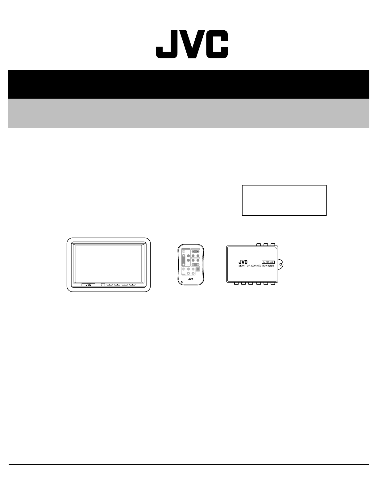
6.5-INCH WIDE COLOR MONITOR
KV-MH6500
Area Suffix
J -------------- Northern America
E ------------ Continental Europe
MONITOR
TV TUNER
T
V
C
H
SKI
P
MOD
E
A.MEM
O
VOCA
L
MENU
R F
H/P
VOLUM
E
CA
LL
VCP
RM-RK500
TABLE OF CONTENTS
1 PRECAUTION. . . . . . . . . . . . . . . . . . . . . . . . . . . . . . . . . . . . . . . . . . . . . . . . . . . . . . . . . . . . . . . . . . . . . . . . . 1-3
2 SPECIFIC SERVICE INSTRUCTIONS. . . . . . . . . . . . . . . . . . . . . . . . . . . . . . . . . . . . . . . . . . . . . . . . . . . . . . 1-4
3 DISASSEMBLY . . . . . . . . . . . . . . . . . . . . . . . . . . . . . . . . . . . . . . . . . . . . . . . . . . . . . . . . . . . . . . . . . . . . . . . 1-5
4 ADJUSTMENT . . . . . . . . . . . . . . . . . . . . . . . . . . . . . . . . . . . . . . . . . . . . . . . . . . . . . . . . . . . . . . . . . . . . . . . . 1-8
5 TROUBLESHOOTING . . . . . . . . . . . . . . . . . . . . . . . . . . . . . . . . . . . . . . . . . . . . . . . . . . . . . . . . . . . . . . . . . . 1-9
COPYRIGHT © 2003 VICTOR COMPANY OF JAPAN, LIMITED
No.49795
2003/11
Page 2
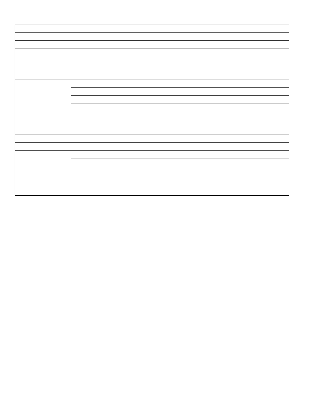
WIDE COLOR MONITOR
Display 6.5 inch Liquid crystal panel
Number of Pixel 280, 800 pixels (400 vertical × 234 horizontal × 3)
Drive Method TFT (Thin Film Transistor) active matrix format
Dimensions (W × H × D) 184 mm × 124 mm × 31 mm including Shroud
Mass 325 g including Shroud
MONITOR CONNECTION UNIT
Input Video RCA pin × 2 circuits 1 V(p-p), 75 Ω
Audio RCA pin × 2 circuits 0.5 V(rms)
Tuner 8-pin DIN connector (only for JVC's KV-C10)
Output Display 13-pin DIN connector
Video RCA pin × 1 circuit 1 V(p-p), 75 Ω
Audio RCA pin × 1 circuit 0.5 V(rms)
Dimensions (W × H × D) 108.5 mm × 28.5 mm × 78 mm excluding projections
Mass 160 g
GENERAL
Power Requirement Operating Voltage DC 14.4 V (11 V to 16 V allowance)
Grounding System Negative ground
Allowable Operating Temperature 0°C to +40°C
Allowable Storage Temperature -20°C to +80°C
ACCESSORIES Mounting spacer × 1, Shroud × 1, System cord × 1, Power cord × 1, Remote controller (with the battery)
× 1, Paper pattern × 1
Design and specifications are subject to change without notice.
The liquid crystal panel is built with very high precision technology and has at leas t 99.99% effecti ve image pixels. Be aware that
on 0.01% of the panel there may be missing pixels or constantly lit pixels.
1-2 (No.49795)
Page 3

1.1 Safety Precautions
SECTION 1
PRECAUTION
!
Burrs formed during molding may be left over on some parts of the chassis. Therefore,
pay attention to such burrs in the case of preforming repair of this system.
(No.49795)1-3
Page 4

SECTION 2
SPECIFIC SERVICE INSTRUCTIONS
This service manual does not describe SPECIFIC SERVICE INSTRUCTIONS.
1-4 (No.49795)
Page 5

SECTION 3
DISASSEMBLY
3.1 Monitor unit section
3.1.1 Removing the bottom cover aseembly
(See Fig.1)
(1) Remove the four screws A attaching the bottom cover as-
sembly on the back of the monitor unit.
(2) Release the two claws a atta ching the bottom cover as-
sembly.
3.1.2 Removing the monitor board
(See Fig.2)
• Prior to performing the following procedure, remove the bottom
cover aseembly.
(1) Disconnect the three connectors J2
monitor board.
(2) Remove the four screws B attaching the monitor board.
(3) Remove the solder from the PVC wire b on the jack board.
3.1.3 Removing the jack board
(See Fig.2 to 3)
• Prior to performing the following procedure, remove the bottom
cover aseembly and remove the monitor board aseembly.
(1) Remove the two screws C attaching the jack board on the
back of the monitor uboard.
(2) Remove 11 solders b on the jack board.
, J3 and M3 on the
J2
Claw a
Claw a
J3
Bottom cover assembly
AA
Fig.1
Monitor board
M3
Jack board
Solders b
PVC wire b
BB
Fig.2
C
Monitor board
Jack board
Fig.3
(No.49795)1-5
Page 6

3.1.4 Removing the TFT LCD panel
(See Fig.4)
• Prior to performing the following procedure, remove the bottom
cover aseembly and remove the monitor board aseembly.
(1) Remove the four screws D attaching the top cover assem-
bly.
TFT LCD panel
DD
Fig.4
1-6 (No.49795)
Page 7

3.2 Monitor connection box section
3.2.1 M onitor connection box
(Figs.5 to 6)
(1) Remove the screws A attaching the monitor connectoin
box.
(2) Release the bottom cover in the directi on arrow.
A
Fig.5
Fig.6
(No.49795)1-7
Page 8

SECTION 4
ADJUSTMENT
This service manual does not describe ADJUSTMENT.
1-8 (No.49795)
Page 9

SECTION 5
TROUBLESHOOTING
This service manual does not describe TROUBLESHOOTING.
(No.49795)1-9
Page 10

VICTOR COMPANY OF JAPAN, LIMITED
AV & MULTIMEDIA COMPANY MOBILE ENTERTAINMENT CATEGORY 10-1,1chome,Ohwatari-machi,Maebashi-city,371-8543,Japan
(No.49795)
Printed in Japan
WPC
 Loading...