

Page 1
6.5-INCH WIDE COLOR MONITOR KV-MH6500
;
;
;;;;;;
;
;
;
;
;
;
;
;
;
MONITOR COLOR DE PANTALLA ANCHA
DE 6,5-PULGADAS KV-MH6500
MONITEUR COULEUR À ÉCRAN LARGE
DE 6,5 POUCES KV-MH6500
MONITOR
TV TUNER
TV
CH
;;;;
SKIP
MODE
A.MEMO
;;
;;
;;
VOCAL
MENU
R F
;;
;;;;
;;
;;
H/P
VOLUME
CALL
;;;;;;
;;;;;;
VCP
RM-RK500
ENGLISH
ESPAÑOL
FRANÇAIS
For installation and connections, refer to
the separate manual.
Para la instalación y las conexiones,
refiérase al manual separado.
Pour l’installation et les raccordements,
référez-vous au manuel séparé.
* This system cannot receive television broadcasts and is primarily designed
for use with a VCR or a DVD player. Use the separately sold mobile TV tuner
unit KV-C10 for optional television broadcast reception.
* Este sistema no puede recibir emisiones de televisión y ha sido diseño para
utilizarse esencialmente con un VCR o un reproductor DVD. Utilice la unidad
de sintonizador de TV móvil KV-C10 vendido por separado para una recepción
opcional de emisiones de televisión.
* Ce système ne peut pas recevoir les émissions de télévision et il est
essentiellement conçu pour l’utilisation avec un magnétoscope ou un lecteur
de DVD. Utilisez le module de tuner de télévision mobile KV-C10 vendu
séparément afin de pouvoir recevoir les émissions de télévision.
INSTRUCTIONS
MANUAL DE INSTRUCCIONES
MANUEL D’INSTRUCTIONS
For customer Use:
Enter below the Model No. and Serial
No. which are located on the top or
bottom of the cabinet. Retain this
information for future reference.
Model No.
Serial No.
LVT0989-001A
[J]
Page 2
WARNING:
TO PREVENT FIRE OR SHOCK
HAZARD, DO NOT EXPOSE THIS
UNIT TO RAIN OR MOISTURE.
ENGLISH
CAUTION:
This monitor system should be used with DC 12V only.
To prevent electric shocks and fire hazards, DO NOT
use any other power source.
Installation requires some special
knowledge.
Do not install the monitor system
yourself. Consult a dealer having
special knowledge of this kind for safe
and reliable installation.
WARNINGS
• DO NOT INSTALL THE MONITOR IN A LOCATION WHICH
OBSTRUCTS DRIVING, VISIBILITY OR WHICH IS
PROHIBITED BY APPLICABLE LAWS AND
REGULATIONS.
• THERE MAY BE LEGAL REGULATIONS DEFINING THE
PERMISSIBLE INSTALLATION LOCATIONS FOR THE
DISPLAY UNIT WHICH DIFFER BY COUNTRY OR BY
STATE. BE SURE TO INSTALL THE DISPLAY UNIT IN A
CORRECT LOCATION ACCORDING TO SUCH LAWS.
• DO NOT INSTALL THE MONITOR IN A LOCATION WHICH
OBSTRUCTS THE OPERATION OF AN AIR BAG.
• THE DRIVER MUST NOT OPERATE THE MONITOR
SYSTEM WHILE DRIVING.
OPERATING THE MONITOR WHILE DRIVING MAY LEAD
TO CARELESSNESS AND CAUSE AN ACCIDENT.
* STOP YOUR VEHICLE IN A SAFE LOCATION WHEN
OPERATING THE MONITOR.
• THE DRIVER MUST NOT WATCH THE TELEVISION OR
VIDEOS WHILE DRIVING.
IF THE DRIVER WATCHES THE TELEVISION OR A VIDEO
WHILE DRIVING, IT MAY LEAD TO CARELESSNESS
AND CAUSE AN ACCIDENT.
• WHEN LIGHTNING OCCURS, DO NOT TOUCH THE
ANTENNA WIRE OR THE TELEVISION.
TOUCHING THE ANTENNA WIRE OR THE TELEVISION
UNDER SUCH CONDITIONS MAY CAUSE
ELECTROCUTION.
• KEEP THE MONITOR AT AN APPROPRIATE SOUND
LEVEL WHILE DRIVING.
DRIVING WITH THE SOUND AT A LEVEL THAT
PREVENTS YOU FROM HEARING SOUNDS OUTSIDE
OF AND AROUND THE VEHICLE MAY CAUSE AN
ACCIDENT.
• ASK A TRAINED TECHNICIAN TO INSTALL THE
MONITOR SYSTEM.
INSTALLATION AND WIRING REQUIRE TRAINING AND
EXPERIENCE.
* TO BE SAFE, ASK THE SALES OUTLET WHERE YOU
PURCHASED THE MONITOR SYSTEM TO PERFORM THE
INSTALLATION.
• BE SURE NOT TO LET THE MONITOR FALL OR BE
STRONGLY IMPACTED SINCE THIS MAY CAUSE A
MALFUNCTION OR FIRE.
• DO NOT USE THE MONITOR WITH THE ENGINE OFF.
WATCHING THE MONITOR WITH THE ENGINE OFF WILL
CONSUME BATTERY POWER AND MAY PREVENT THE
ENGINE FROM STARTING.
2
Page 3
Thank you for purchasing a JVC product. Please read all instructions carefully before operation, to
ensure your complete understanding and to obtain the best possible performance from the unit.
CONTENTS
PRECAUTIONS ............................................................ 4
CONTROLS AND FEATURES ......................................... 5
Wide color monitor ......................................................................... 5
Remote controller ........................................................................... 6
Replacing the battery ..................................................................... 7
BASIC OPERATIONS.................................................... 8
When you use JVC FM modulator KS-IF200 ............................. 9
Selecting the RF signals to the receiver ...................................... 9
ADJUSTMENTS ......................................................... 10
Using the Menu ............................................................................. 10
Basic procedure ......................................................................... 10
Adjustable items on the menu ................................................... 11
MAINTENANCE ........................................................ 13
TROUBLESHOOTING ................................................. 14
SPECIFICATIONS ....................................................... 15
ENGLISH
BEFORE USE
* For safety....
• Do not raise the volume level too much, as this
will block outside sounds, making driving
dangerous.
• Stop the car before performing any complicated
operations.
* Temperature inside the car....
If you have parked the car for a long time in hot
or cold weather, wait until the temperature in the
car becomes normal before operating the unit.
3
Page 4
PRECAUTIONS
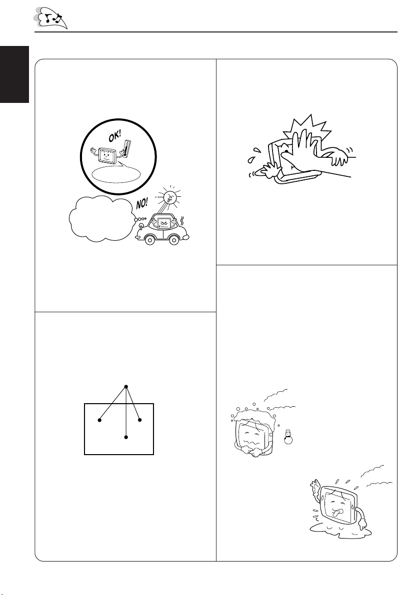
Cautions for handling the liquid crystal panel
Do not expose the liquid crystal display to
direct sunlight.
ENGLISH
• Storage temperature range:
–20 °C to +80 °C
+80°C
–20°C
–20°C to +80°C
During the summer,
temperatures can
reach as high as
100 °C.
When the liquid crystal panel reaches high
temperatures or low temperatures, chemical
changes occur within the liquid crystal panel
which may cause it to malfunction.
The red spots, blue spots and green spots
on the panel surface are a normal
characteristic of liquid crystal panels, and
not a problem.
Do not drop the liquid crystal display or strike
it sharply.
When the temperature is very cold or very
hot, the image may not appear clearly or
may move slowly.
The image may not be synchronized with
the sound or the image quality may decline
in such environments. Note that this is not
a malfunction or problem.
• Usage temperature range: 0 °C to +40 °C
Spots
The liquid crystal panel is built with very high
precision technology and has at least
99.99% effective image pixels. Be aware
that on 0.01% of the panel there may be
missing or constantly light pixels.
4
0 °C or colder
40 °C or hotter
Page 5
CONTROLS AND FEATURES
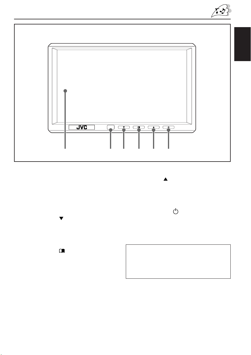
Wide color monitor
654321
ENGLISH
1 Screen (Liquid crystal panel)
2 Remote sensor
Aim at this area when operating the
monitor from the remote controller.
3 Down button (
Decrease the adjustment level of (or select
an appropriate setting for) the item
selected by the Menu button.
4 Menu button ( )
Select an adjustment item.
)
5 Up button (
Increase the adjustment level of (or select
an appropriate setting for) the item
selected by the Menu button.
6 Power button ( )
• Press to turn on the power.
Each time you press the button, the input
mode changes when the power is on.
• Press and hold to turn off the power.
Note:
When you watch the screen at an angle, the
picture might not be clear. This is not a
malfunction. The finest picture can be seen
when you watch the screen straight-on.
)
5
Page 6
Remote controller RM-RK500
;
;
;
;
;
;
;
;
;
;
;
;
;
;
;
;
;
;
;
;
;
;
;
;
;
;
;
;
;
;
;
;
;
;
;
;
;
;
;
;
;
;
;
;
;
;
;
;
;
;
;
;
;
;
;
;
;
;
;
;
;
;
;
;
;
;
;
;
;
;
;
;
;
;
;
;
;
;
;
;
;
;
;
;
;
;
;
;
;
;
;
;
;
;
;
;
;
;
;
Monitor section
ENGLISH
1
2
3
MONITOR
;;;;;;
MODE
;;;;;;
;;;;;;
;;;;;;
;;;;;;
;;;;;;
;;;;;;
;;;;;;
;;;;;;
MENU
;;;;;;
;;;;;;
;;;;;;
;;;;;;
;;;;;;
;;;;;;
;;;;;;
;;;;;;
;;;;;;;;;;;;;;;;;
;;;;;;;;;;;;;;;;;
;;;;;;;;;;;;;;;;;
;;;;;;;;;;;;;;;;;
;;;;;;;;;;;;;;;;;
;;;;;;;;;;;;;;;;;
VCP
TV TUNER
TV
CH
;;;;;;;;;;;
;;;;;;;;;;;
;;;;;;;;;;;
;;;;;;;;;;;
;;;;;;;;;;;
SKIP
;;;;;;;;;;;
VOCAL
;;;;;;;;;;;
;;;;;;;;;;;
;;;;;;;;;;;
;;;;;;;;;;;
H/P
VOLUME
A.MEMO
R F
CALL
4
5
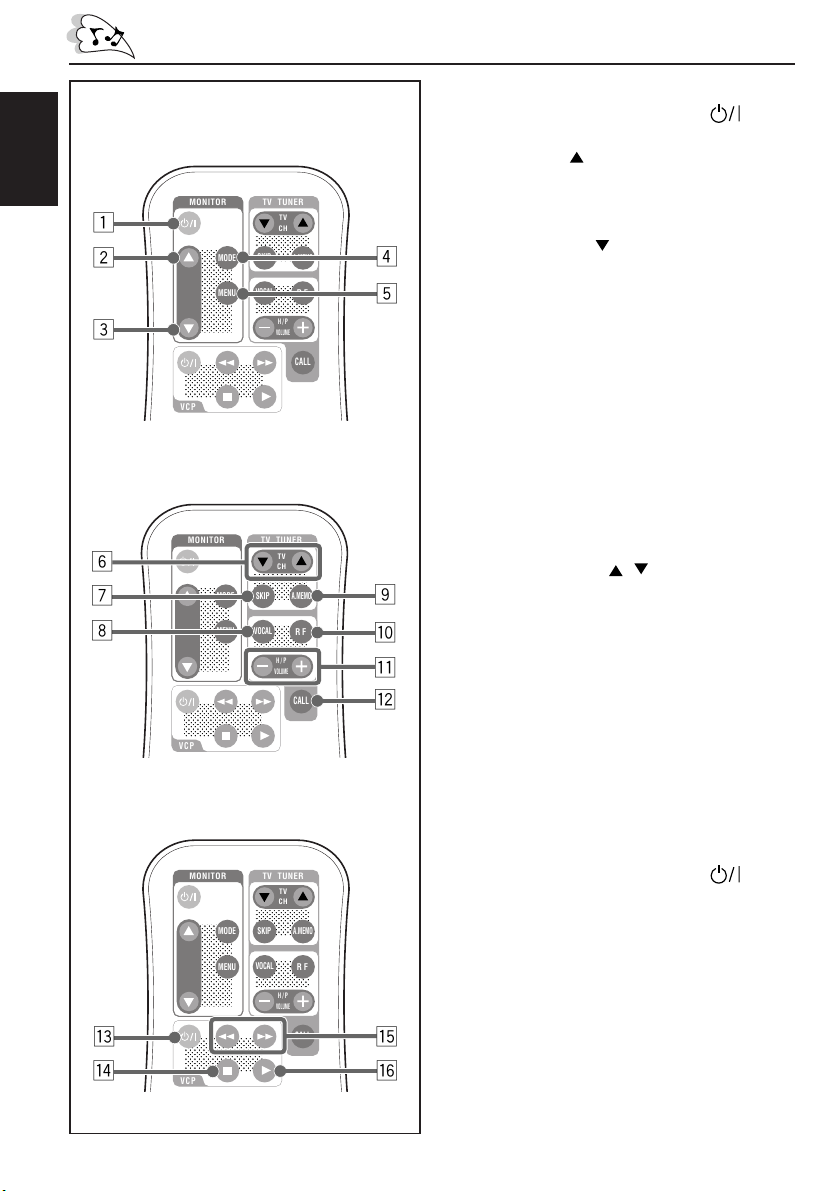
Monitor section
1 Power On/Standby button (
Turn on or off the monitor system.
2 Up button (
)
Increase the adjustment level of (or select
an appropriate setting for) the item
selected by the MENU button.
3 Down button ( )
Decrease the adjustment level of (or select
an appropriate setting for) the item
selected by the MENU button.
4 MODE button
Each time you press the button, the input
mode changes.
5 MENU button
Call up or erase the Menu screen.
)
TV tuner section
MONITOR
6
;;;;;;
7
8
Video cassette player section
e
r
6
;;;;;;
;;;;;;
;;;;;;
;;;;;;
;;;;;;
;;;;;;
;;;;;;
;;;;;;
;;;;;;
;;;;;;
;;;;;;
;;;;;;
;;;;;;
;;;;;;
;;;;;;
;;;;;;
;;;;;;;;;;;;;;;;;
;;;;;;;;;;;;;;;;;
;;;;;;;;;;;;;;;;;
;;;;;;;;;;;;;;;;;
;;;;;;;;;;;;;;;;;
;;;;;;;;;;;;;;;;;
VCP
MONITOR
;;;;;;
;;;;;;
;;;;;;
;;;;;;
;;;;;;
;;;;;;
;;;;;;
;;;;;;
;;;;;;
;;;;;;
;;;;;;
;;;;;;
;;;;;;
;;;;;;
;;;;;;
;;;;;;
;;;;;;
;;;;;;;;;;;;;;;;;
;;;;;;;;;;;;;;;;;
;;;;;;;;;;;;;;;;;
;;;;;;;;;;;;;;;;;
;;;;;;;;;;;;;;;;;
;;;;;;;;;;;;;;;;;
VCP
MODE
MENU
MODE
MENU
TV TUNER
TV
CH
;;;;;;;;;;;
;;;;;;;;;;;
;;;;;;;;;;;
;;;;;;;;;;;
;;;;;;;;;;;
SKIP
;;;;;;;;;;;
VOCAL
;;;;;;;;;;;
;;;;;;;;;;;
;;;;;;;;;;;
;;;;;;;;;;;
H/P
VOLUME
TV TUNER
TV
CH
;;;;;;;;;;;
;;;;;;;;;;;
;;;;;;;;;;;
;;;;;;;;;;;
;;;;;;;;;;;
SKIP
;;;;;;;;;;;
VOCAL
;;;;;;;;;;;
;;;;;;;;;;;
;;;;;;;;;;;
;;;;;;;;;;;
H/P
VOLUME
A.MEMO
R F
CALL
A.MEMO
R F
CALL
9
p
q
w
t
y
TV tuner section
The following buttons can be used for operating
JVC’s KV-C10.
• For specific operations, refer to the instructions
for the KV-C10.
6 TV CH buttons ( / )
7 SKIP button
8 VOCAL button
9 A.MEMO (auto memory) button
p RF (radio frequency) button
q H/P (headphones) VOLUME buttons
(+/–)
w CALL button
Video cassette player (VCP) section
The following buttons can be used for operating
JVC’s KV-V8 or KV-V10.
• For specific operations, refer to the instructions
for the KV-V8 or KV-V10
e Power On/Standby button (
)
r 7 (Stop) button
t 1 (Rewind)/¡ (Fast-forward)
buttons
y 3 (Play) button
Page 7

Before using the remote controller:
When you use the remote controller for the
first time, pull out the insulation sheet as
illustrated to the right.
• Aim the remote controller directly at the
remote sensor on the color monitor. Make
sure there is no obstacle in between.
• Do not expose the remote sensor to strong
light (direct sunlight or artificial lighting).
Replacing the battery
When the controllable range or effectiveness
of the remote controller decreases, replace
the battery.
1. Remove the battery holder.
While pushing in the lock using a ball-point
pen or a similar tool (1), pull out the
battery holder in the direction indicated by
the arrow (2).
(back side)
2
1
2. Replace the battery.
Slide a new battery into the holder with
the + side facing upwards so that the
battery is fixed in the holder.
(back side)
ENGLISH
Pull out
Insulation sheet
(The battery has been installed when shipped
from the factory.)
WARNING:
• Store the battery in a place which children
cannot reach.
If a child accidentally swallows the battery,
immediately consult a doctor.
• Do not recharge, short, disassemble or heat
the battery or dispose of in a fire.
Doing any of these things may cause the
battery to give off heat, crack or start a fire.
• Do not leave the battery with other metallic
materials.
Doing this may cause the battery to give off
heat, crack or start a fire.
• When throwing away or saving the battery,
wrap in tape and insulate; otherwise, it may
cause the battery to give off heat, crack or
start a fire.
• Do not poke the battery with tweezers or
similar tools.
Doing this may cause the battery to give off
heat, crack or start a fire.
Lithium coin battery
(product number:
CR2025)
3. Return the battery holder.
Insert the battery holder again pushing it
until you hear a clicking sound.
(back side)
CAUTION:
DO not leave the remote controller in a place
(such as dashboard) exposed to direct sunlight
for a long time. Otherwise, it may be damaged.
7
Page 8
BASIC OPERATIONS
;
;
;
;
;
;
;
;
;
;
;
;
;
;
;
;
;
;
;
;
;
;
;
;
;
;
;
;
;
VIDEO 1
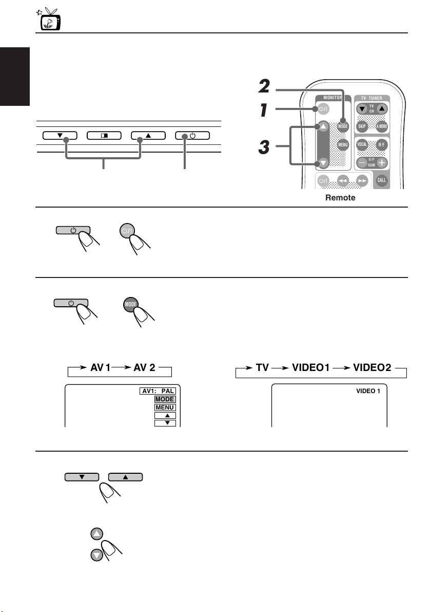
Preparation
Before operating the monitor system, make sure that all external components are
correctly connected and installed.
ENGLISH
2
1
3
3
Monitor
1, 2
1
Turn on the power.
Monitor Remote
2
MODE
Monitor Remote
• When KV-C10 is not connected: • When KV-C10 is connected:
AV 1
AV 2
Select the input source.
Each time you press the button, the input source changes
as follows:
TV
VIDEO 1
MONITOR
;;;;;;
;;;;;;
MODE
;;;;;;
;;;;;;
;;;;;;
;;;;;;
;;;;;;
;;;;;;
;;;;;;
MENU
;;;;;;
;;;;;;
;;;;;;
;;;;;;
;;;;;;
;;;;;;
;;;;;;
;;;;;;
;;;;;;
;;;;;;;;;;;;;;;;;
;;;;;;;;;;;;;;;;;
Remote
TV TUNER
TV
CH
;;;;;;;;;;;
;;;;;;;;;;;
;;;;;;;;;;;
;;;;;;;;;;;
SKIP
A.MEMO
;;;;;;;;;;;
VOCAL
R F
;;;;;;;;;;;
;;;;;;;;;;;
;;;;;;;;;;;
;;;;;;;;;;;
H/P
VOLUME
CALL
VIDEO 2
AV1: PAL
MODE
MENU
Ex. When “AV 1” is selected
Ex. When “VIDEO 1” is selected
3
Select the video format— PAL or NTSC, while
the indication of the video format is still on the
Monitor
8
Remote
screen.
Each time you press the button, the video format
alternates between PAL (initial setting) and NTSC. Select
whichever matches to the incoming signals.
Note:
When not using the KV-C10: You can preset the video format
separately for “AV 1” and “AV 2.”
Page 9
4
Play back the external component.
To operate the external components, refer to the manuals for the connected
components.
5
Select the external component and adjust the volume on the car
receiver.
ENGLISH
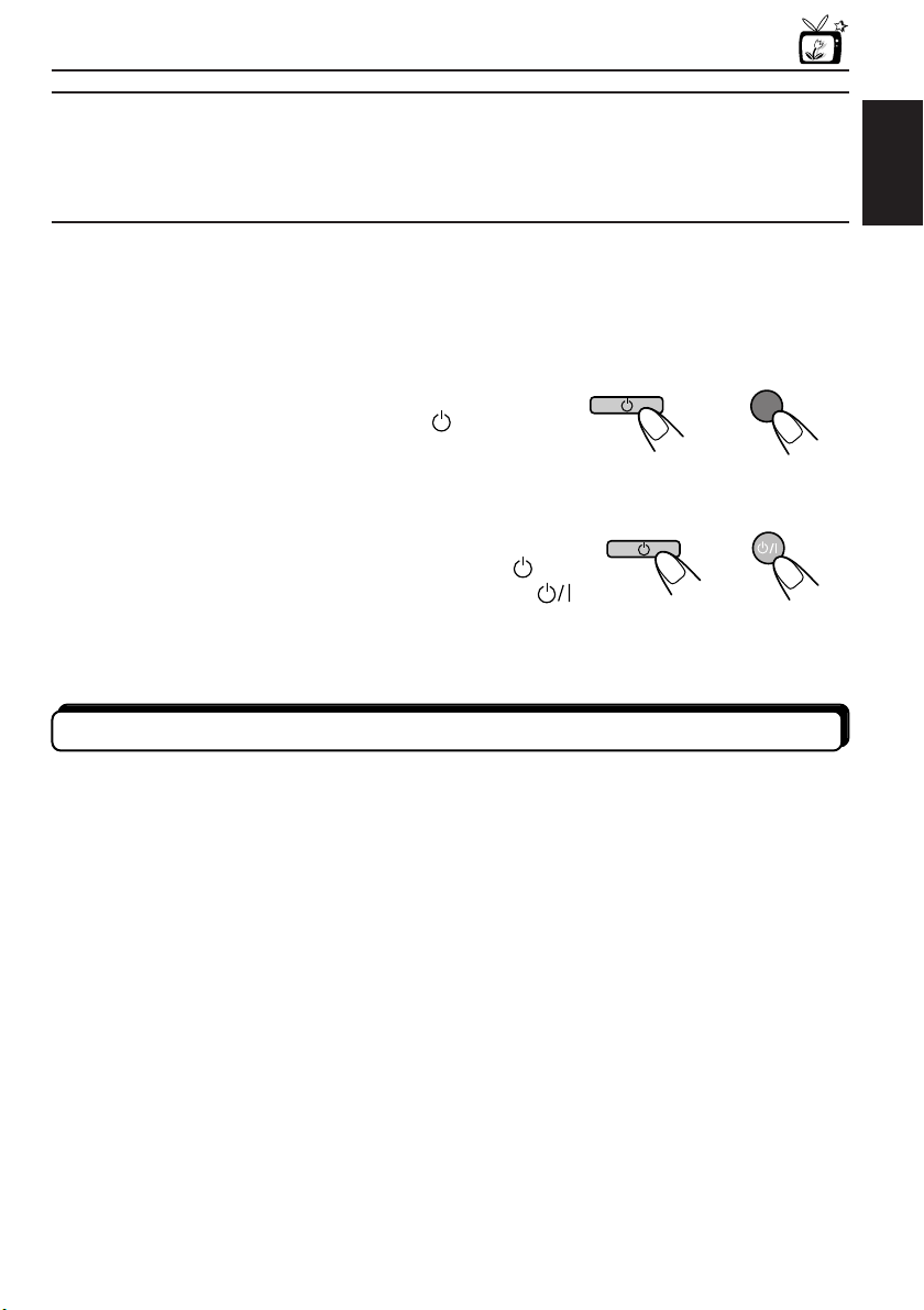
To check the current input source
On the monitor: Press the Power button ( ) once.
On the remote: Press the MODE button once.
The on-screen display appears for about 5 seconds.
Monitor Remote
MODE
To turn off the power
On the monitor: Press and hold the Power button ( ).
On the remote: Press the Power On/Standby button (
) .
Monitor Remote
When you use JVC FM modulator KS-IF200
Selecting the RF signals to the receiver
You can listen to playback sounds from the external component through the receiver even if
it is equipped with no line input.
• Refer also to the instructions of KS-IF200.
When KV-C10 is connected:
Press the RF button on the remote controller.
Each time you press the button, “RF ON” and “RF OFF” alternate and the sounds you hear
through the car speakers change accordingly.
RF ON : Select to listen to the sound of the external component.
RF OFF : Select to listen to the radio (through the receiver).
9
Page 10
ADJUSTMENTS
;
;
;
;
;
;
;
;
;
;
;;;;;;;;;;;;
;
;
;
;
;
;
;
;
;
;
;
;
;
;
;
;
;
;
;
;
;
;
;
;
;
;
;
;;;;;;;;;;;;
;
;
;
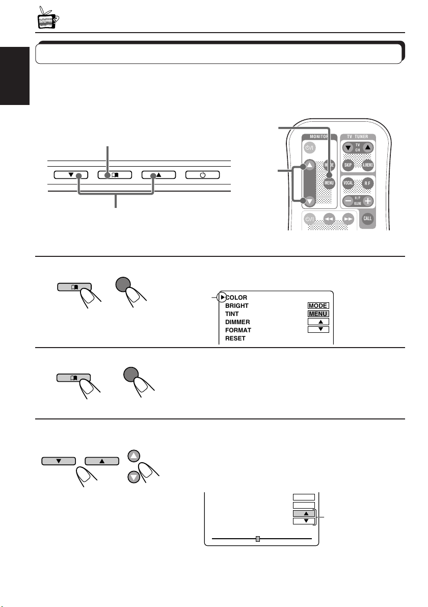
Using the Menu
You can make your own adjustments using the Menu.
• For the adjustable items, see the next page.
ENGLISH
Basic procedure
1, 2, 4
1
Monitor Remote
2
Monitor Remote
3
Monitor
MENU
MENU
1, 2, 4
3
MONITOR
;;;;;;;
MODE
;;;;;;;
;;;;;;;
;;;;;;;
;;;;;;;
;;;;;;;
;;;;;;;
;;;;;;;
;;;;;;;
MENU
;;;;;;;
;;;;;;;
;;;;;;;
;;;;;;;
;;;;;;;
;;;;;;;
;;;;;;;
;;;;;;;
;;;;;;;;;;;;;;;;
;;;;;;;;;;;;;;;;
;;;;;;;;;;;;;;;;
TV TUNER
TV
CH
;;;;;;;;;;
;;;;;;;;;;
;;;;;;;;;;
;;;;;;;;;;
;;;;;;;;;;
SKIP
;;;;;;;;;;
VOCAL
;;;;;;;;;;
;;;;;;;;;;
;;;;;;;;;;
;;;;;;;;;;
H/P
VOLUME
A.MEMO
R F
CALL
Remote
Call up the Menu.
Cursor
COLOR
BRIGHT
TINT
DIMMER
FORMAT
RESET
MODE
MENU
Select an item you want to adjust.
Each time you press the button, the cursor moves to the
next item.
10
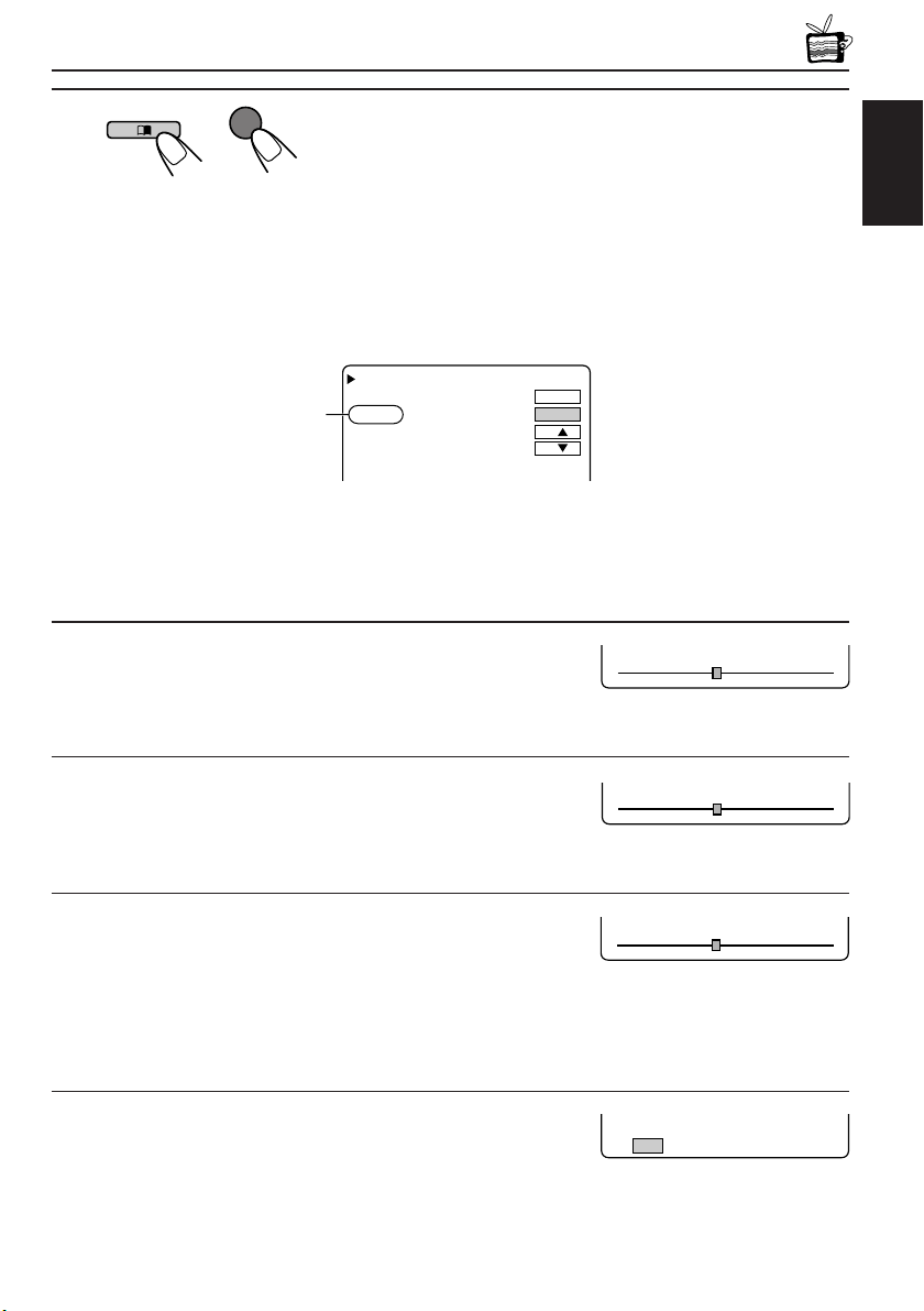
3
Adjust the level of the selected item (or select
an appropriate setting for the selected item).
• When “RESET” is selected in the above step, the Color,
Brightness, and Tint settings are reset.
Monitor Remote
TINT 32
Ex: When adjusting Tint
MODE
MENU
Activated button is
highlighted.
Page 11
4
BRIGHT 32
TINT 32
DIMMER
OFF ON
MENU
Exit from the Menu.
• Press the button repeatedly until the Menu is erased.
Monitor Remote
Adjustable items on the menu
COLOR
Appears only for
NTSC video format
Note:
Menu goes off if no operation is done for about 5 seconds.
BRIGHT
TINT
DIMMER
FORMAT
RESET
MODE
MENU
ENGLISH
COLOR : Adjust the color of the picture—lighter or
darker.
• Adjustable range: 0 to 63
• Initial level: 32
BRIGHT : Adjust this if the picture is too bright or too
dark.
• Adjustable range: 0 to 63
• Initial level: 32
TINT : Adjust this if the human skin color is unnatural.
• Adjustable range: 0 to 63
• Initial level: 32
Note:
This can be shown and adjusted when the video
format is NTSC.
DIMMER : Activate the dimmer if the inside of the car is
too bright to view the picture on the screen.
• Selectable settings: ON/OFF
• Initial setting: OFF
COLOR 32
CONTINUED ON THE NEXT PAGE
11
Page 12

FORMAT : Select an appropriate display size.
FORMAT FULL
MODE
MENU
COLOR
BRIGHT
TINT
RESET
32
32
32
• Selectable settings: FULL/NORMAL/ZOOM
• Initial setting: FULL
ENGLISH
When viewing 16:9 video signals:
FULL: Pictures are fully shown on the screen.
• The black bars will be shown both at the top and the bottom of
the screen.
NORMAL: Pictures are shown at the center of the screen.
ZOOM: Pictures are enlarged on the screen so that no black bars will be
shown on the screen. (The entire picture cannot be shown on
the screen.)
FULL
NORMAL
ZOOM
When viewing 4:3 video signals:
FULL: Pictures are enlarged horizontally and are fully shown on the
screen.
NORMAL: Pictures are shown at the center of the screen.
• The black bars will be shown at the left and right sides of the
screen.
ZOOM: Pictures are enlarged on the screen so that no black bars will be
shown on the screen. (The entire picture cannot be shown on
the screen.)
FULL
RESET : Reset the Color, Brightness, and Tint levels
to the initial settings.
12
NORMAL
ZOOM
Page 13

MAINTENANCE
To prevent damage to the exterior
• Do not apply pesticides, benzine, thinner or other volatile substances to the unit.
The cabinet surface primarily consists of plastic materials.
• Do not wipe with benzine, thinner or similar substances because this will results in
discoloration or removal of the paint.
• When a cloth with a cleansing chemical is used, follow the caution points.
– Do not leave the unit in contact with rubber or vinyl products for long periods of time.
– Do not use cleansers which have polishing granules because this could damage the
surface of the unit.
Clean off dirt by wiping lightly with a soft cloth
When the unit is very dirty, wipe with a well-wrung cloth dipped in a kitchen cleanser (neutral)
thinned by water and then go over the same surface with a dry cloth.
(Since there is the possibility of water drops getting inside of the unit, do not directly apply
cleanser to the surface.)
Caution:
If water drops or similar wet substances get inside of the monitor via the liquid crystal panel surface,
it may cause a malfunction.
ENGLISH
13
Page 14

TROUBLESHOOTING
What appears to be trouble is not always serious. Check the following points before calling a
service center.
ENGLISH
Symptoms
• Colored spots (red, blue and
green) appear on the screen.
• No picture appears and sound
is not heard.
• Picture shakes vertically or
colors are abnormal.
• Remote controller does not
work.
Causes
This is a characteristic of liquid
crystal panels and is not a
malfunction.
Correct input mode is not
selected.
The video format (NTSC/PAL) is
not correct.
The battery has lost its charge.
Remote sensor is exposed to
strong light.
Remedies
See “Note” on page 15.
Select the correct input mode.
Select the correct video format.
Install a new battery.
Do not expose the remote
sensor to strong light.
14
Page 15
SPECIFICATIONS
WIDE COLOR MONITOR
Display:
6.5 inch Liquid crystal panel
Number of Pixel:
280 800 pixels
×
(400 vertical
Drive Method:
TFT (Thin Film Transistor) active matrix
format
Dimensions (W × H × D):
184 mm × 124 mm × 31 mm
including Shroud
Mass: 325 g including Shroud
234 horizontal × 3)
MONITOR CONNECTION
UNIT
Input
Video: RCA pin × 2 circuits
1 V(p-p), 75 Ω
Audio: RCA pin × 2 circuits
0.5 V(rms)
Tuner: 8-pin DIN connector
(only for JVC’s KV-C10)
Output
Display:
13-pin DIN connector
Video: RCA pin × 1 circuit
1 V(p-p), 75 Ω
Audio: RCA pin × 1 circuit
0.5 V(rms)
Dimensions (W × H × D):
108.5 mm × 28.5 mm × 78 mm
excluding projections
Mass: 160 g
GENERAL
Power Requirement
Operating Voltage:
DC 14.4 V (11 V to 16 V allowance)
Grounding System:
Negative ground
Allowable Operating Temperature:
0°C to +40°C
Allowable Storage Temperature:
–20°C to +80°C
ACCESSORIES
Mounting spacer × 1
Shroud × 1
System cord × 1
Power cord × 1
Remote controller (with the battery) × 1
Paper pattern × 1
Design and specifications are subject to change
without notice.
Note:
The liquid crystal panel is built with very high
precision technology and has at least 99.99%
effective image pixels. Be aware that on 0.01%
of the panel there may be missing pixels or
constantly lit pixels.
ENGLISH
15
Page 16

VICTOR COMPANY OF JAPAN, LIMITED
EN, GE, FR, NL
© 2003 VICTOR COMPANY OF JAPAN, LIMITED
0303MNMMDWPUN
JVC
Page 17
KV-MH6500
AV1
VIDEO
A
V2
L A
U
D
IO
R
L
A
U
D
IO
R
V
ID
E
O
AV OUT
R AUDIO L
VIDEO
13 PIN
TO MONITOR
8 PIN
TO TV TUNER
IN
P
U
T
2
INPUT 1
;
;
;
;
;
;
;
;
;
;
;
;
;
;
;
;
;
Installation/Connection Manual
Einbau/Anschlußanleitung
Manuel d’installation/raccordement
Handleiding voor installatie/aansluiting
LVT0990-004A
[E]
0303MNMMDWPUN
JVC
EN, GE, FR, NL
ENGLISH
WARNING
Installation requires some special knowledge.
Do not install the monitor system yourself.
Consult a dealer having special knowledge of
this kind for safe and reliable installation.
• DO NOT INSTALL THE MONITOR IN A LOCATION
WHICH OBSTRUCTS DRIVING, VISIBILITY OR
WHICH IS PROHIBITED BY APPLICABLE LAWS
AND REGULATIONS.
If the monitor is installed in a location which obstructs
forward visibility or operation of the air bag or other
safety equipment or which interferes with operation
of the vehicle, it may cause an accident.
• NEVER USE BOLTS OR NUTS FROM THE
VEHICLE’S SAFETY DEVICES FOR
INSTALLATION.
If bolts or nuts from the steering wheel, brakes or other
safety devices are used for installation of the monitor,
it may cause an accident.
• ATTACH THE WIRES CORRECTLY.
If the wiring is not correctly performed, it may cause a
fire or an accident. In particular, be sure to run and
secure the lead wire so that it does not get tangled
with a screw or the moving portion of a seat rail.
• USE WITH DC 12 V NEGATIVE GROUND
VEHICLES.
This monitor system is only for use in a DC 12 V
negative ground vehicle.
It cannot be used in large trucks or diesel vehicles
which are DC 24 V vehicles.
If it is used in the wrong type of vehicle, it may
cause a fire or accident.
• To prevent short circuits, we recommend that you
disconnect the battery’s negative terminal and make
all electrical connections before installing the unit. If
you are not sure how to install this unit correctly, have
it installed by a qualified technician.
• Avoid installing the monitor connection unit in the
following places
– Where it would hinder your safe driving.
– Where it would be exposed to direct sunlight or heat
directly from the heater or placed in an extremely
hot place.
– Where it would be subject to rain, water splashes
or excessive humidity.
– Where it would be subject to dust.
– Where it would be positioned on an unstable place.
– Where it could damage the car’s fittings.
– Where proper ventilation would not be maintained,
such as under a floor mat.
CAUTION
Since there may be legal regulations defining the
permissible installation locations for the color
monitor which differ by country or by state, be sure
to install the color monitor in a location complying
with any such laws.
DEUTSCH
WARNUNGEN
Die Installation erfordert entsprechende
Fachkenntnisse.
Installieren Sie das Monitorsystem nicht selbst.
Wenden Sie sich für eine sichere und fachgerechte
Installation an einen Vertragshändler.
• INSTALLIEREN SIE DEN MONITOR NICHT AN
EINEM ORT, AN DEM DAS FÜHREN DES
FAHRZEUGS ODER DIE SICHT BEEINTRÄCHTIGT WIRD ODER DER AUFGRUND
GELTENDER GESETZE UND VERORDNUNGEN
UNZULÄSSIG IST.
Wenn Sie den Monitor an einem Ort installieren, an dem
die Voraussicht oder der Betrieb des Airbags oder
anderer Sicherheitseinrichtungen des Fahrzeugs
beeinträchtigt wird oder das Führen des Fahrzeugs
gestört wird, kann er die Ursache für einen Unfall sein.
• VERWENDEN SIE NIEMALS SCHRAUBEN ODER
MUTTERN DER SICHERHEITSEIN-RICHTUNGEN
DES FAHRZEUGS ZUR INSTALLATION.
Wenn Schrauben oder Muttern des Lenkrads, der
Bremsen oder anderer Sicherheitsein-richtungen zur
Installation des Monitors verwendet werden, kann
ein Unfall verursacht werden.
•
BRINGEN SIE DIE DRÄHTE ORDNUNGSGEMÄSS AN.
Wenn die Verkabelung nicht richtig durchgeführt wird,
entsteht hierdurch möglicherweise ein Feuer oder
Unfall. Achten Sie insbesondere darauf, das Kabel
so zu verlegen und zu sichern, daß es sich nicht mit
einer Schraube oder dem beweglichen Teil einer
Sitzschiene verheddert.
• VERWENDEN SIE DAS GERÄT NUR IN
FAHRZEUGEN MIT 12-V-GLEICHSTROM-SYSTEM
UND NEGATIVER ERDUNG.
Dieser Monitor darf nur in Fahrzeugen mit einem
12-V-Gleichstromsystem und Negativer Erdung
verwendet werden.
Er darf nicht in großen Lkw oder Diesel-fahrzeugen
mit 24-V-Gleichstrom-systemen verwendet werden.
Wenn der Monitor im falschen Fahrzeugtyp
verwendet wird, kann er ein Feuer oder einen Unfall
verursachen.
• Um einen Kurzschluß zu vermeiden, empfiehlt es
sich, den negativen Pol der Batterie abzutrennen und
alle elektrischen Anschlüsse vorzunehmen, bevor der
Monitor installiert wird. Wenn Sie sich nicht sicher sind,
wie das Gerät installiert wird, lassen Sie es von einem
qualifizierten Techniker einbauen.
• Die Monitor-Anschlußeinheit nicht an den
folgenden Orten installieren
– an denen die Fahrsicherheit gefährdet wäre.
– an denen es direkter Sonneneinstrahlung oder
Hitzeeinwirkung durch die Heizung ausgesetzt
wäre. Installieren Sie es auch nicht an einem
extrem heißen Ort.
– an denen es Regen, Wasserspritzern oder
übermäßiger Feuchtigkeit ausgesetzt wäre.
– an denen es Staub ausgesetzt wäre.
– die instabil sind.
– an denen die Fahrzeugarmaturen beschädigt
werden könnten.
– an denen keine ordnungsgemäße Belüftung
aufrechterhalten werden kann, z.B. unterhalb von
Bodenmatten.
VORSICHT
Da es möglicherweise gesetzliche Vorschriften gibt,
mit denen zulässige Installationsorte für den
Farbmonitor geregelt werden und die von Staat zu
Staat oder Bundesland zu Bundesland unterschiedlich sein können, vergewissern Sie sich, daß
Sie den Farbmonitor an einem Ort installieren, der
mit den gesetzlichen Vorschriften im Einklang steht.
FRANÇAIS NEDERLANDS
AVERTISSEMENT
L’installation nécessite certaines
connaissances spéciales.
N’installez pas le moniteur vous-même.
Consultez un revendeur possédant les
connaissances spéciales nécessaires pour une
installation correcte et sûre.
•
N’INSTALLEZ PAS LE MONITEUR DANS UN
ENDROIT QUI GÊNE LA CONDUITE, LA VISIBILITÉ
OU QUI EST INTERDIT PAR LE CODE DE LA ROUTE
ET LES RÈGLEMENTS.
Si le moniteur était installé à un emplacement gênant
la visibilité avant, ou le déploiement du sac à air, et
autres dispositifs de sécurité, ou à un emplacement
gênant pour la conduite du véhicule, comme près du
levier des vitesses ou de la pédale du frein, cela
risquerait de provoquer des accidents.
• NE JAMAIS UTILISER POUR L’INSTALLATION
DES BOULONS OU DES ÉCROUS PROVENANT
DES DISPOSITIFS DE SÉCURITÉ DU VÉHICULE.
Si l’on utilisait pour l’utilisation du moniteur des boulons
et des écrous cannibalisés du volant, des freins ou
autres dispositifs de sécurités, cela risquerait de
provoquer des accidents.
• ATTACHER LES CORDONS CORRECTEMENT.
Si le câblage n’est pas exécuté correctement, cela
risque de provoquer un incendie ou autre accident.
Veiller, en particulier, à tirer et attacher les fils en sorte
qu’ils me s’accrochent pas à une vis ou ne se coincent
dans les parties mobiles des rails des sièges.
• USAGE SUR LES VÉHICULES DE 12 V CC AVEC
NÉGATIF À LA MASSE.
Ce moniteur ne peut être utilisé que sur les véhicules
de 12 V CC avec négatif à la masse.
Il ne peut pas être utilisé sur les gros camions ou les
véhicules diesel de 24 V CC.
S’il était utilisé sur un type de véhicule inadéquat cela
risquerait de provoquer un incendie ou autres
accidents.
• Pour éviter les courts-circuits, nous
recommandons que vous déconnectiez la borne
négative de la batterie et réalisiez toutes les
connexions électriques avant d’installer l’appareil. Si
vous n’êtes pas sûr de savoir comment installer cet
appareil correctement, faites-le installer par un
technicien qualifié.
•
Évitez d’installer l’unité de connexion du
moniteur dans les endroits suivants
– Où il peut gêner la conduite de la voiture.
– Où il est exposé à la lumière directe du soleil, à la
chaleur directe du chauffage ou placé dans un
endroit très chaud.
– Où il est sujet à la pluie, aux éclaboussures ou à
une humidité excessive.
– Où il est sujet à la poussière.
– Où il est positionné dans un endroit instable.
– Où il peut endommager les accessoires de la
voiture.
– Où une ventilation correcte ne peut pas être
maintenue, comme sous un tapis de sol.
ATTENTION
Il peut y avoir des réglementations définissant les
emplacements d’installation autorisés pour un
moniteur couleur et celles-ci peuvent varier d’une
région à l’autre. Assurez-vous d’installer le moniteur
dans un endroit conforme à ces lois.
WAARSCHUWING
Het installeren vereist een specifieke kennis.
Installeer het monitorsysteem derhalve niet zelf.
Raadpleeg de plaats van aankoop of een vakman
die deze speciale kennis heeft voor het veilig en
betrouwbaar installeren.
• INSTALLEER DE MONITOR NIET OP EEN
PLAATS WAAR DIT HET RIJDEN, OF HET
UITZICHT BELEMMERT, OF WAAR DIT BIJ WET
OF ANDERE REGELGEVING IS VERBODEN.
Als de monitor op een plaats is geïnstalleerd waar dit het
uitzicht op de weg belemmert, dit de werking van de airbag
of dit andere veiligheidsvoorzieningen hindert, of waar het
besturen van het voertuig in gevaar wordt gebracht, kan dit
tot een ongeval lijden.
• GEBRUIK NOOIT SCHROEVEN OF MOEREN
VOOR DE INSTALLATIE DIE NODIG ZIJN VOOR DE
VEILIGHEIDSVOORZIENINGEN VAN DE AUTO.
Als schroeven of moeren van het stuur, de rem of andere
veiligheidsvoorzieningen worden gebruikt voor de
installatie van de monitor, kan dit tot een ongeval lijden.
• SLUIT DE BEDRADING OP DE JUISTE WIJZE AAN.
Als de bedrading verkeerd wordt aangesloten, kan dit tot
brand of een ongeval lijden. Let er met name op dat de
stroomvoorzieningskabel nergens achter blijft steken of in
contact komt met de bewegende delen van de rails van de
stoelen.
• ALLEEN GEBRUIKEN IN COMBINATIE MET
VOERTUIGEN DIE WERKEN MET EEN NEGATIEVE
AARDING VAN 12 V GELIJKSTROOM.
Dit monitorsysteem is alleen bedoeld voor voertuigen die
zijn gebaseerd op een negatieve aarding van 12 V
gelijkstroom.
Het systeem kan niet worden gebruikt in vrachtwagens of
diesels, die met 24 V gelijkstroom werken.
Wanneer dit systeem in een verkeerd type voertuig wordt
gebruikt, kan dit tot brand of een ongeval lijden.
• Ter voorkoming van kortsluiting, raden we aan dat u
de negatieve aansluiting van de accu losmaakt en daarna
alle benodigde verbindingen tot stand brengt alvorens de
eenheid te installeren. Als u niet zeker weet hoe u de eenheid
moet installeren, kunt u dit beter door een erkend vakman
laten doen.
• Installeer het monitor-aansluitgedeelte niet op de
volgende plaatsen
– waar deze een gevaar vormt voor het besturen van de
auto.
– waar deze wordt blootgesteld aan direct zonlicht, een
verwarming of een andere hittebron.
– waar deze wordt blootgesteld aan regen, spatwater of
extreme vochtigheid.
– waar deze wordt blootgesteld aan stof.
– waar deze op een instabiele ondergrond komt te staan.
– waar deze de auto kan beschadigen.
– waar geen ventilatie is, zoals onder een vloermat.
LET OP!
Mogelijk zijn er in uw land of regio wetten of
bepalingen die de installatie van de kleurenmonitor op
bepaalde plaatsen in de auto verbieden. Installeer de
kleurenmonitor altijd in overeenstemming met
dergelijke regelgeving.
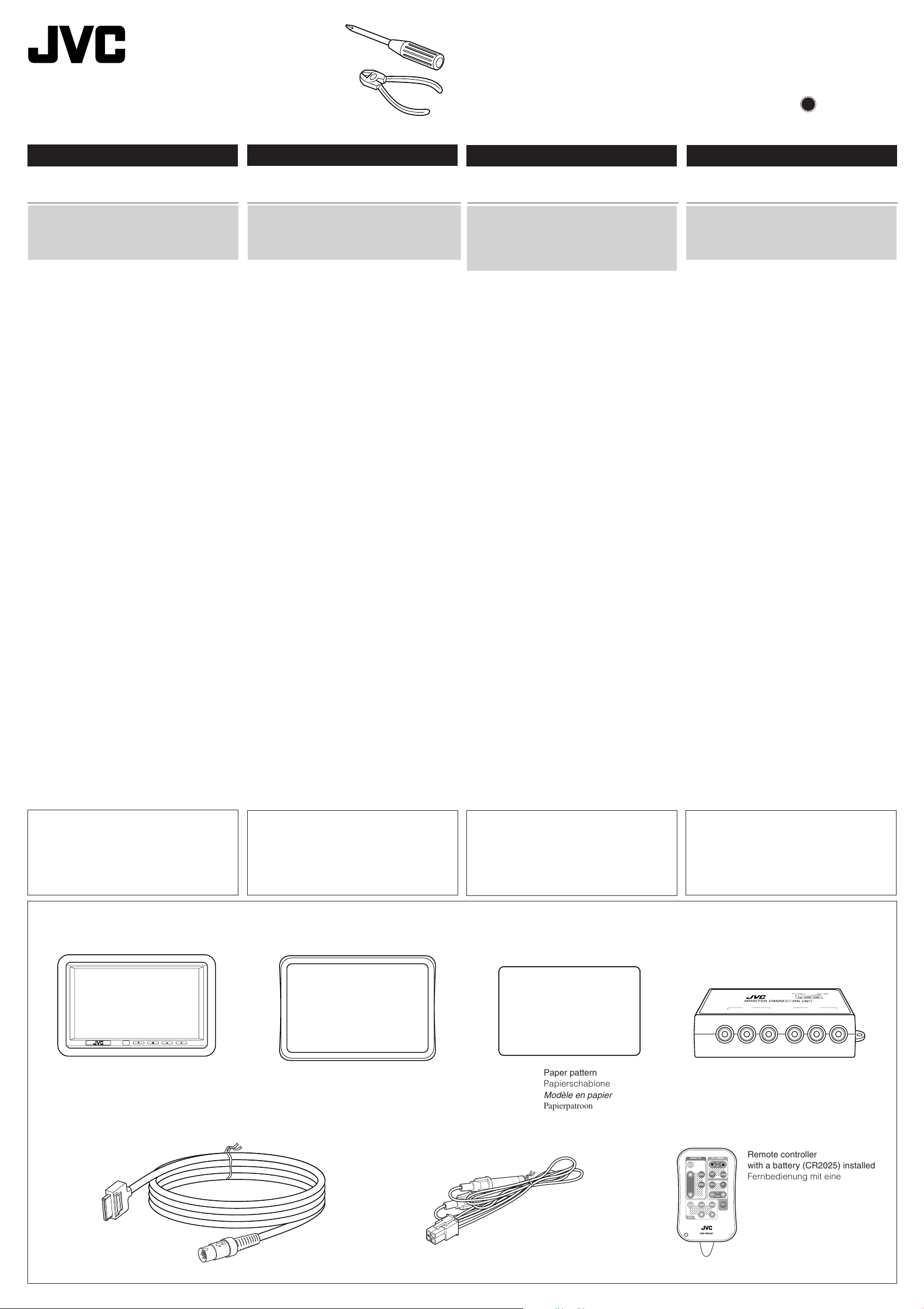
Parts list for installation and connection
The following parts are provided with this unit.
After checking them, please set them correctly.
Wide color monitor (center unit and shroud)
Breitbild-Farbmonitor
(Mittlere Einheit und Abschirmung)
Moniteur couleur à écran large
(unité centrale et socle
de montage au plafond)
Breedkleur-monitor
(centrale toestel en versteviging)
Teileliste für den Einbau und Anschluß
Die folgenden Teile werden zusammen mit diesem
Gerät geliefert.
Nach ihrer Überprüfung, die Teile richtig einsetzen.
Mounting spacer
Montagerahmen
Entretoise de montage
Tussenstuk voor bevestiging
System cord (3 m)
Systemkabel (3 m)
Cordon de système (3 m)
Systeemsnoer (3 meter)
Liste des pièces pour l’installation et
raccordement
Les pièces suivantes sont fournies avec cet appareil.
Après vérification, veuillez les placer correctement.
Paper pattern
Papierschablone
Modèle en papier
Papierpatroon
Power cord
Spannunsgversorgungskabel
Cordon d’alimentation
Electriciteitskabel
– 1 –
Lijst van onderdelen die u bij installatie
en aansluiting nodig hebt
De volgende onderdelen worden bij het apparaat geleverd.
Installeer ze op de juiste wijze, nadat u ze hebt gecontroleerd.
Monitor connection unit
Monitor-Anschlußeinheit
Unité de connexion du moniteur
Aansluitgedeelte van de monitor
MONITOR
;;;;
;;;;
;;;;
;;;;
;;;;
;;;;
;;;;
;;;;
;;;;
;;;;;;;;;
;;;;;;;;;
;;;;;;;;;
VCP
MODE
MENU
RM-RK500
TV TUNER
;;;;;;
;;;;;;
SKIP
;;;;;;
VOCAL
;;;;;;
;;;;;;
Remote controller
TV
CH
with a battery (CR2025) installed
A.MEMO
Fernbedienung mit einer
R F
eingebauten Batterie des Typs
H/P
VOLUME
CR2025
CALL
Télécommande
avec une pile en place (CR2025)
Afstandsbediening met een batterij
(CR2025) geplaatst
Page 18
INSTALLATION
Einbau
INSTALLATION
INSTALLATIE
• The following illustration shows a typical installation.
However, you should make adjustments
corresponding to your specific car. If you have any
questions or require information regarding
installation kits, consult your JVC IN-CAR
ENTERTAINMENT dealer or a company supplying
kits.
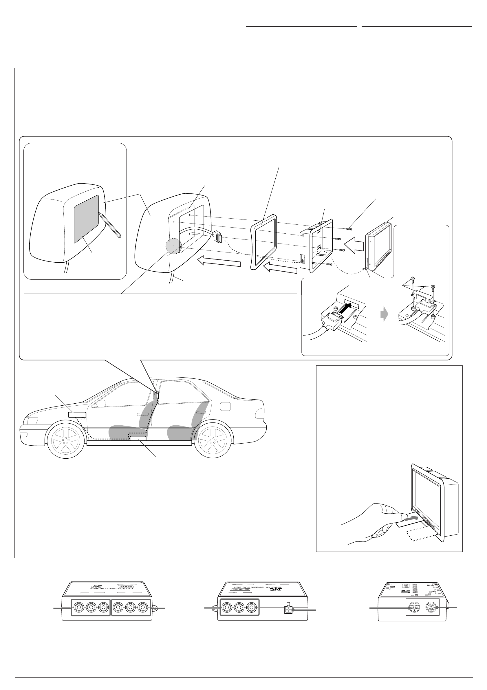
Mounting the color monitor
It is recommended to have the monitor system
installed by a qualified technician.
Before mounting the monitor to the headrest:
• Perform the required external connections first.
• Using the supplied paper pattern, mark the area to
be cut out of the headrest, then carefully cut it.
• Die folgende Abbildung zeigt einen typischen
Einbau. Dennoch müssen Sie entsprechend Ihrem
jeweiligen Auto Anpassungen vornehmen. Bei
irgendwelchen Fragen oder wenn Sie Informationen
hinsichtlich des Einbausatzes brauchen, wenden
Sie sich an ihren
JVC-Autoradiofachhändler
oder
ein Unternehmen das diese Einbausätze vertreibt.
Monitor befestigen
Es wird empfohlen, daß das Monitorsystem durch
einen qualifizierten Techniker installiert wird.
Vor der Installation des Monitors an der Decke
Kopfstütze:
• Schließen Sie die externen Anschlüsse zuerst an.
• Markieren Sie mit Hilfe der mitgelieferten
Papierschablone den Bereich auf der Kopfstütze,
der ausgeschnitten werden soll und schneiden Sie
•
L’illustration suivante est un exemple d’installation
typique. Cependant, vous devez faire les ajustements
correspondant à votre voiture particulière. Si vous
avez des questions ou avez besoin d’information sur
des kits d’installation, consulter votre revendeur
d’autoradios JVC ou une compagnie
d’approvisionnement.
Montage du moniteur couleur
Il est recommandé de faire installer le système de
moniteur par un technicien qualifié.
Avant de fixer le moniteur au repose-tête:
•
Réalisez d’abord les connexions extérieures
nécessaires.
•
En utilisant le modèle en papier fourni, marquez la
zone à couper sur le repose-tête, puis coupez-la
avec précaution.
den Bereich vorsichtig aus.
Mounting spacer (if required to fit the shroud to the rear surface of the headrest)
Mark the area to be cut out, and carefully cut it.
Markieren Sie den Bereich, der ausgeschnitten
werden soll und schneiden Sie den Bereich
vorsichtig aus.
Marquez la zone à couper et coupez-la avec
précaution.
Markeer het uit te snijden gedeelte en snijd vervolgens
voorzichtig uit.
Headrest
Kopfstütze
Repose-tête
Installation plate (not supplied)
Montageplatte (nicht mitgeliefert)
Plaque d’installation (non fournis)
Installatieplaat (niet bijgeleverd)
Montagerahmen (wenn zur Befestigung der Abschirmung an der Hinterseite der Kopfstütze notwendig)
Entretoise de montage (s’il est nécessaire de monter le socle de montage sur la surface arrière du
repose-tête)
Tussenstuk voor bevestiging (indien de versterking aan de achterkant van de hoofdsteun moet worden bevestigd)
Hoofdsteun
Paper pattern
Papierschablone
Modèle en papier
Papierpatroon
System cord (from the monitor connection unit)
Systemkabel (vom Monitoranschluss)
Cordon de système (à partir de l’unité de connexion)
Systeemsnoer (vanaf het aansluitgedeelte van de monitor)
• For safety, use neither a sharp-pointed screw nor a long screw which will protrude more than 5 mm from the
back of the installation plate.
• Aus Sicherheitsgründen verwenden Sie weder eine spitze Schraube noch eine lange Schraube, die mehr
als 5 mm aus der Rückseite der Montageplatte hervorsteht.
• Pour des raisons de sécurité, n’utilisez jamais une vis pointue ni une vis longue qui dépasse de plus de
5 mm de l’arrière de la plaque d’installation.
• Gebruik voor de veiligheid beslist geen schroef met scherpe punt of een lange schroef die meer dan 5 mm
vanaf de achterkant van de installatieplaat zou uitsteken.
Shroud
Abschirmung
Socle de montage au
plafond au plafond
Versteviging
• Op de volgende afbeelding kunt u zien hoe de installatie,
normaal gesproken, in zijn werk gaat. U moet echter bij
de installatie rekening houden met de bijzonderheden
van uw eigen auto. Neem bij vragen of voor meer
bijzonderheden over inbouwpakketten contact op met uw
JVC auto audiohandelaar of een dealer of een bedrijf dat
inbouwpakketten levert.
Bevestigen van de kleurenmonitor
Laat bij voorkeur het monitorsysteem door een
erkend technicus installeren.
Alvorens de monitor aan het plafond te hoofdsteun:
• Maak eerst de vereiste externe verbindingen.
• Gebruik het bijgeleverde papierpatroon, markeer het uit
te snijden gedeelte van de hoofdsteun en snijd het
gemarkeerde gedeelte vervolgens uit.
Screws (not supplied)
Schrauben (nicht mitgeliefert)
Vis (non fournis)
Schroeven (niet bijgeleverd)
Center unit
Mittlere Einheit
Unité centrale
Centrale toestel
* Attached to the center
unit when purchased.
* Beim Kauf an der
Mittlere Einheit
befestigt.
* Fixées à l’unité
centrale à l’achat.
* Bij aankoop aan het
centrale toestel bevestigd.
*
VCR or DVD/CD receiver, etc.
Videorecorder oder DVD-/CD-Reciever usw.
Magnétoscope, recepteur DVD/CD, etc.
Videocassettespeler, DVD/CD-receiver, enz.
Monitor connection unit
Monitor-Anschlußeinheit
Unité de connexion du moniteur
Aansluitgedeelte van de monitor
CAUTION / VORSICHT / ATTENTION / LET OP!:
• Take preventative measures to avoid unexpected disconnection of the cord and damage to the cord by being caught somewhere. This
trouble may happen while adjusting the headrest position or while moving or reclining the seat.
• Stellen Sie sicher, dass das Kabel nicht unbeabsichtigt abgezogen und eingeklemmt werden kann—Dies kann geschehen, wenn die
Kopfstütze bewegt, der Sitz verschoben oder die Rückenlehne nach hinten bewegt wird.
• Prenez des mesures préventives pour éviter que le cordon soit déconnecté accidentellement ou coincé quelque part—Cela peut se
produire quand vous bougez le repose-tête, ou quand vous bougez ou inclinez le siège.
• Neem voorzorgsmaatregelen zodat het snoer niet onverwachts los kan schieten en ergens tussen kan worden vastgekneld—Het
snoer zou anders namelijk los kunnen schieten bij het verstellen van de hoofdsteun of het verplaatsen of verstellen van de stoel.
How to detach the center unit from the shroud
So entfernen Sie die mittlere Einheit von der
Abschirmung
Comment détacher l’unité centrale du socle de
montage
Verwijderen van het centrale toestel van de
versteviging
Release the lock levers by inserting something like a card into
the gap between the center unit and the shroud, then remove
the center unit.
Entriegeln Sie die Verriegelungshebel, indem Sie einen
Kunststoffstreifen o. ä. in den Zwischenraum zwischen der
mittleren Einheit und der Abschirmung schieben und die
mittlere Einheit entfernen.
Libérez les leviers de verrouillage en insérant quelque chose
comme une carte dans l’espace entre l’unité centrale et le socle
de montage, puis retirez l’unité centrale.
Ontgrendel de vergrendelhendels door
bijvoorbeeld een kaart in de opening tussen het
centrale toestel en de versteviging te steken en
verwijder vervolgens het centrale toestel.
Monitor connection unit /Monitor-Anschlußeinheit / Unité de connexion du moniteur / Aansluitgedeelte van de monitor
L AU R
Front
Vorderseite
Avant
TO MONITOR
8 PIN
TO TV TUNER
13 PIN
L A
V
ID
E
O
Voor
1
1 AV 2 (INPUT 2) jacks
• VIDEO/AUDIO L (left)/AUDIO R (right)
2 AV 1 (INPUT 1) jacks
• VIDEO/AUDIO L (left)/AUDIO R (right)
3 AV OUT jacks
• VIDEO/AUDIO L (left)/AUDIO R (right)
4 Power Supply connector
5 TO MONITOR (13 PIN) connector
6 TO TV TUNER (8 PIN) connector
L
DIO
VIDEO
AU
R
AV OUT
IN
P
U
T
2
AV2
U
D
IO
R
VIDEO
INPUT 1
AV1
L AUDIO R
Back
Rückseite
Arrière
VIDEO
VIDEO
AV1
INPUT 1
AV OUT
R AUDIO L
Achter
2
1 AV 2 (INPUT 2) Anschlüsse
• VIDEO/AUDIO L (links)/AUDIO R (rechts)
2 AV 1 (INPUT 1) Anschlüsse
• VIDEO/AUDIO L (links)/AUDIO R (rechts)
3 AV OUT Anschlüsse
• VIDEO/AUDIO L (links)/AUDIO R (rechts)
4 Stromversorgungsanschluß
5 TO MONITOR (13 PIN) Anschluß
6 TO TV TUNER (8 PIN) Anschluß
3
1
Prises AV 2 (INPUT 2)
•
VIDEO/AUDIO L (gauche)/AUDIO R (droit)
2
Prises AV 1 (INPUT 1)
•
VIDEO/AUDIO L (gauche)/AUDIO R (droit)
3
Prises AV OUT
•
VIDEO/AUDIO L (gauche)/AUDIO R (droit)
4
Connecteur d’alimentation
5
Connecteur TO MONITOR (13 PIN)
6
Connecteur TO TV TUNER (8 PIN)
– 2 –
AV2
IN
P
U
T 2
VIDEO
L AUDIO R
TO TV TUNER
8 PIN
TO MONITOR
13 PIN
4
Side
Seitenansicht
Côté
Zijkant
5
1 AV 2 (INPUT 2) aansluitingen
• VIDEO/AUDIO L (links)/AUDIO R (rechts)
2 AV 1 (INPUT 1) aansluitingen
• VIDEO/AUDIO L (links)/AUDIO R (rechts)
3 AV OUT aansluitingen
• VIDEO/AUDIO L (links)/AUDIO R (rechts)
4 Aansluiting voor stroomtoevoer
5 TO MONITOR (13 PIN) aansluiting
6 TO TV TUNER (8 PIN) aansluiting
6
Page 19

ENGLISH
DEUTSCH FRANÇAIS NEDERLANDS
ELECTRICAL CONNECTIONS
To prevent short circuits, we recommend that you
disconnect the battery’s negative terminal and make all
electrical connections before installing the unit. If you
are not sure how to install this unit correctly, have it
installed by a qualified technician.
Note:
This unit is designed to operate on 12 V DC, NEGATIVE
ground electrical systems. If your vehicle does not
have this system, a voltage inverter is required, which
can be purchased at JVC car audio.
• Replace the fuse with one of the specified ratings. If
the fuse blows frequently, consult your JVC IN-CAR
ENTERTAINMENT dealer.
ELEKTRISCHE ANSCHLÜSSE
Zur Vermeidung von Kurzschlüssen empfehlen wir, daß
Sie den negativen Batterieanschluß abtrennen und alle
elektrischen Anschlüsse herstellen, bevor das Gerät
eingebaut wird. Sind Sie sich über den richtigen Einbau
des Geräts nicht sicher, lassen Sie es von einem
qualifizierten Techniker einbauen.
Hinweis:
Dieses Gerät ist für den Betrieb in elektrischen
Anlagen mit 12 V Gleichstrom und (–) Erdung
ausgelegt. Verfügt Ihr Fahrzeug nicht über diese
Anlage, ist ein Spannungsinverter erforderlich, der
bei JVC-Autoradiofachhändler erworben werden
kann.
• Die Sicherung mit einer der entsprechenden
Nennleistung ersetzen. Brennt die Sicherung
häufig durch, wenden Sie sich an ihren JVCAutoradiofachhändler.
RACCORDEMENTS ELECTRIQUES
Pour éviter tout court-circuit, nous vous
recommandons de débrancher la borne négative de
la batterie et d’effectuer tous les raccordements
électriques avant d’installer l’appareil. Si l’on n’est pas
sûr de pouvoir installer correctement cet appareil, le
faire installer par un technicien qualifié.
Remarque:
Cet appareil est conçu pour fonctionner sur des
sources de courant continu de
NEGATIVE
d’alimentation, il vous faut un convertisseur de
tension, que vous pouvez acheter chez un revendeur
d’autoradios JVC.
• Remplacer le fusible par un de la valeur précisée. Si
le fusible saute souvent, consulter votre revendeur
d’autoradios JVC
. Si votre véhicule n’offre pas ce type
.
Typical Connections / Typische Anschlüsse / Raccordements typiques / Normale verbindingen
Before connecting: Check the wiring in the vehicle
carefully. Incorrect connection may cause serious
damage to this unit.
The leads of the power cord and the ceiling light cord
and those of the connector from the car body may be
different in color.
7 Power supply connection
1
Connect the colored leads of the power cord to
the car battery, remote control and parking brake
in the following sequence.
1 Black: ground
2 Yellow: to car battery (constant 12 V)
3 Red: to an accessory terminal
4 Blue: to remote control lead of the external
component (such as KS-IF200)
2
Finally connect the wiring harness to the unit.
Vor dem Anschließen: Die Verdrahtung im Fahrzeug
sorgfältig überprüfen. Falsche Anschlüsse können
ernsthafte Schäden am Gerät hervorrufen.
Die Kabel von Stromversorgung, Innenbeleuchtung
und der Anschluss zur Fahrzeugmasse haben
möglicherweise unterschiedliche Farben.
7 Stromversorgungsanschluß
1
Schließen Sie die farbigen Kabel des
Spannunsgversorgungskabels in der folgenden
Reihenfolge an die Autobatterie, Fernbedienung
und Feststellbremse an.
1 Schwarz: an Erde
2 Gelb: an die Autobatterie (12 V Gleichstrom)
3 Rot: an den Hilfsanschluß
4 Blau: an Fernsteuerkabel der externen
Komponente (wie z. B. KS-IF200)
2
Schließen Sie zum Schluß den Kabelbaum an das
Gerät an.
Avant de commencer la connexion:
attentivement le câblage du véhicule. Une connexion
incorrecte peut endommager sérieusement l’appareil.
Les fils du cordon d’alimentation et du cordon du
plafonnier et ceux du connecteur provenant de la
voiture peuvent être de couleur différente.
7 Connexion de l’alimentation
1
Connectez les fils de couleur du cordon
d’alimentation à la batterie de la voiture, aux
enceintes et à l’antenne automatique (s’il y en a
une) dans l’ordre suivant.
1
Noir: à la masse
2
Jaune: à la batterie de la voiture (12 V constant)
3
Rouge: à la prise accessoire
4
Bleu: au fil de télécommande de l’appareil
extérieur (tel que le KS-IF200)
2
Finalement, connectez le faisceau de fils à l’appareil.
12 V à masse
Vérifiez
ELEKTRISCHE VERBINDINGEN
Om kortsluiting te voorkomen adviseren wij u om de
minpool van de accu los te maken en alle elektrische
verbindingen tot stand te brengen voordat u het apparaat in
de auto installeert. Als u niet zeker weet hoe u dit apparaat
moet installeren, kunt u dit beter door een daartoe
gekwalificeerde technicus laten doen.
Opmerking:
Dit apparaat mag worden gebruikt bij elektrische systemen
die werken op 12 V gelijkstroom met negatieve
aarding. Als uw auto niet is uitgerust met een dergelijk
systeem, is een spanningsomzetter vereist. Dit instrument
kan worden aangeschaft bij JVC auto audiohandelaar.
• Vervang de zekering door een exemplaar met het
aangegeven vermogen. Als de zekering vaak doorslaat,
moet u uw JVC auto audiohandelaar raadplegen.
Alvorens de verbindingen tot stand te brengen:
Moet u de bedrading in de auto zorgvuldig. Het apparaat
kan door verkeerde verbindingen ernstige schade oplopen.
De draden van het stroomsnoer en het plafondlicht-snoer
en die van de aansluitingen in de auto zijn mogelijk
verschillend van kleur.
7 Aansluiten van de stroomtoevoer
1
Sluit de gekleurde draden van de stroomtoevoer in de
onderstaande volgorde aan op de accu van de auto, de
afstandsbediening en de parkeerrem:
1 Zwart: aarde
2 Geel: naar de accu van de auto (constant 12 V)
3 Rood: naar het aansluitpunt van een accessoire
4 Blauw: Naar het afstandsbedieningsdraad van het
externe component (bijvoorbeeld de KS-IF200)
2
Sluit tot slot de bedrading naar de eenheid aan.
2
1
Black / Schwarz /
1
Yellow*
1
Gelb*
1
Jaune
*
1
Geel*
Red
Rot
Rouge
Rood
Blue
Blau
Bleu
Blauw
*1: Before checking the operation of this unit prior to installation, this lead must be connected, otherwise power cannot be
*1: Vor der Überprüfung der Funktionsfähigkeit des Geräts vor dem Einbau, muß diese Leitung angeschlossen werden, da
*
1: Pour vérifier le fonctionnement de cet appareil avant installation, ce fil doit être raccordé, sinon l’appareil ne peut pas
*1: Voordat u controleert of het apparaat werkt (alvorens het te installeren), moet deze draad aangesloten zijn. Als dit niet het geval is, kan
Noir
/ Zwart
250V 5A250V 1A
5 A fuse
5 A-Sicherung
Fusible 5 A
5 A zekering
1 A fuse
1 A-Sicherung
Fusible 1 A
1 A zekering
turned on.
sonst die Stromversorgung nicht eingeschaltet werden kann.
être mis sous tension.
de stroom niet worden ingeschakeld.
To metallic body or chassis of the car
Zur Metallkarosserie oder zum Fahrwerk des Fahrzeugs
Vers corps métallique ou châssis du véhicule
1
Naar de metalen ombouw of chassis van de auto
To a live terminal in the fuse block connecting to the car battery (bypassing the ignition switch)
Zu einem stromführenden Anschluß im Sicherungsblock, der an die Autobatterie
angeschlossen ist (Umgehen des Zündschalters)
A une borne sous tension du porte-fusible connectée à la batterie de la voiture (en dérivant
2
l’interrupteur d’allumage)
Naar een aansluiting in het zekeringenblok die op de accu is aangesloten (waarbij de ontsteking wordt omzeilt)
To an accessory terminal in the fuse block
Zu einem Hilfsanschluß im Sicherungsblock
Vers borne accessoire du porte-fusible
3
Naar de aansluiting voor een accessoire in het zekeringenblok
To remote lead of the external component (such as KS-IF200)
An Fernsteuerkabel der externen Komponente (wie z. B. KS-IF200)
Au fil de télécommande de l’appareil extérieur (tel que le KS-IF200)
4
Naar het afstandsbedieningsdraad van het externe component (bijvoorbeeld de KS-IF200)
*
Ignition switch
Zündschalter
Interrupteur d’allumage
Contactschakelaar
2
2
*
Fuse block
Sicherungsblock
Porte-fusible
Zekeringblok
*2Not included with this unit.
*2Wird nicht mit Gerät mitgeliefert.
*2Non fourni avec cet appareil.
*2Niet bij het apparaat inbegrepen.
Connecting the leads / Anschließen der Leitungen / Raccordement des fils / Aansluiting van de gekleurde draden
Twist the core wires when connecting.
Die Kerndrähte beim Anschließen
verdrehen.
Torsader les âmes des fils en les
raccordant.
Draai de kerndraden om elkaar heen
wanneer u ze wilt aansluiten.
TROUBLESHOOTING
• The fuse blows.
* Are the red and black leads connected correctly?
• Power cannot be turned on.
* Is the yellow lead connected?
• Picture does not come on screen.
* Is the correct input selected?
• Picture does not appear clearly.
* Is the color monitor installed at the right angle?
Solder the core wires to connect them securely.
Die Kerndrähte anlöten, um sie fest anzuschließen.
Souder les âmes des fils pour les raccorder entre
eux de façon sûre.
Soldeer de kerndraden zodat ze stevig vast zitten.
FEHLERSUCHE
• Die Sicherung brennt durch.
* Sind das rote und das schwarze Kabel
ordnungsgemäß angeschlossen?
• Die Stromversorgung kann nicht eingeschaltet
werden.
* Ist das gelbe Kabel angeschlossen?
• Auf dem Bildschirm erscheint kein Bild.
* Wurde der richtige Eingang ausgewählt?
• Das Bild scheint nicht klar zu sein.
* Ist der Farbmonitor im richtigen Winkel installiert?
CAUTION / VORSICHT / PRECAUTION / LET OP!:
• To prevent short-circuit, cover the terminals of the UNUSED leads with insulating tape.
• Zur Vermeidung eines Kurzschlusses die Anschlußklemmen der NICHT VERWENDETEN
Leitungen mit Isolierklebeband umwickeln.
• Pour éviter les court-circuits, couvrir les bornes des fils qui ne sont PAS utilisés avec de la
bande isolante.
• Om kortsluiting te voorkomen, moet u de aansluitklemmen van ONGEBRUIKTE gekleurde
draden met isolatieband bedekken.
EN CAS DE DIFFICULTÉS
• Le fusible saute.
* Les fils rouge et noir sont-ils racordés
correctement?
• L’appareil ne peut pas être mise sous tension.
* Le fil jaune est-elle raccordée?
• Aucune image n’apparaît sur l’écran.
*L’entrée correcte est-elle choisie?
• L’image n’apparaît pas clairement.
* Le moniteur couleur est-il installé avec un angle
correct?
PROBLEMEN OPLOSSEN
• De zekering brandt door.
* Zijn de rode en zwarte kabels goed aangesloten?
• De stroom kan niet worden ingeschakeld.
* Is de gele kabel aangesloten?
• Er is geen beeld op het scherm.
* Is de juiste ingang gekozen?
• Het beeld is niet helder.
* Is de kleurenmonitor onder de juiste hoek geïnstalleerd?
– 3 –
Page 20
CONNECTING THE EXTERNAL
ANSCHLIESSEN EXTERNER
CONNEXION DES APPAREILS
DE EXTERNE ONDERDELEN
COMPONENTS
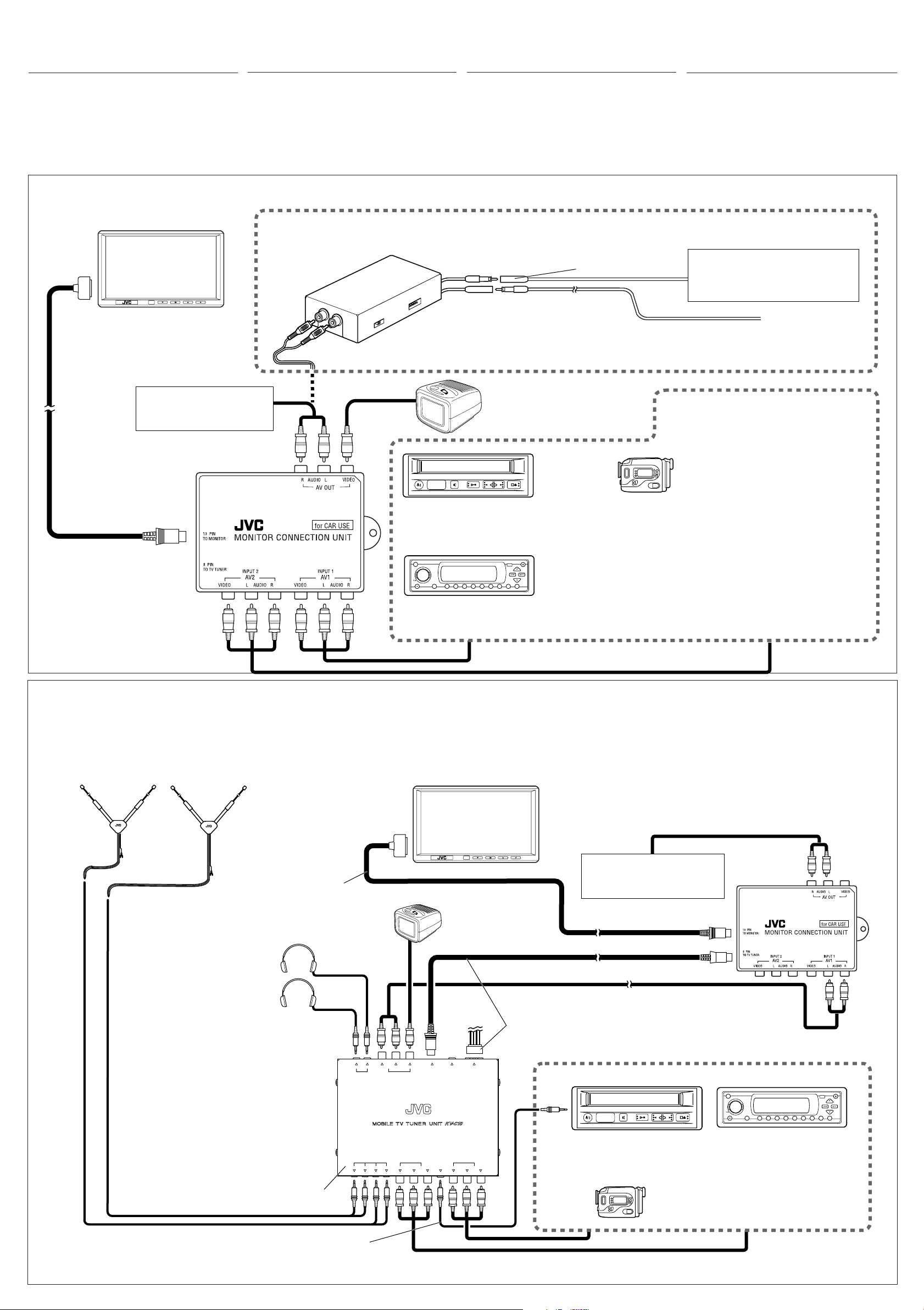
Connect the monitor to TO MONITOR jack using the
system cord supplied with the unit.
The monitor connection unit provides 2 input circuits
and 1 output circuit. Connect one or two playback
sources to AV 1 (INPUT 1) and/or AV 2 (INPUT 2) and
connect reproducing components, such as a car
receiver, to AV OUT.
KOMPONENTEN
Schließen Sie den Monitor an die Buchse mit der
Bezeichnung TO MONITOR mit Hilfe des
Systemkabels an (im Lieferumfang enthalten).
Die Monitor-Anschlußeinheit stellt zwei 2 Eingangsund einen Ausgangskreis zur Verfügung. Schließen
Sie eine oder zwei Wiedergabesignalquellen an AV 1
(INPUT 1) und/oder AV 2 (INPUT 2) und eine
Reproduktionskomponente, z.B. einen Autoreceiver,
EXTÉRIEURS
Connectez le moniteur à la prise TO MONITOR en
utilisant le cordon de système fourni avec cet appareil.
L’unité de connexion du moniteur possède 2 circuits
d’entrée et un circuit de sortie.
sources de lecture à la prise AV 1 (INPUT 1) et/ou à la
prise AV 2 (INPUT 2) et connectez un appareil de
traitement du son tel qu’un récepteur d’autoradio à la AV
OUT.
Connectez une ou deux
AANSLUITEN
Verbind de monitor met de TO MONITOR aansluiting met
gebruik van het bij dit toestel bijgeleverde systeemsnoer.
Het monitor-aansluitgedeelte heeft 2 ingangscircuits en 1
uitgangscircuit. Sluit 1 of 2 afspeelbronnen aan op de AV 1
(INPUT 1)-bus en/of AV 2 (INPUT 2)-bus, en sluit een
reproductiebron, zoals een autoradio-ontvanger, aan op de
AV OUT.
an AV OUT.
• When not using the mobile TV tuner system KV-C10 / Bei Nichtbenutzung des mobilen TV-Tuner-Systems KV-C10 /
Lorsque vous n’utilisez pas le système de tuner de télévision mobile KV-C10 / Indien u het draagbare KV-C10 TV-tunersysteem niet gebruikt
When using KS-IF200 / Bei Verwendung von KS-IF200 / Lors de l’utilisation du KS-IF200 / Bij gebruik van de KS-IF200
Aerial input
Antenneneingang
Wide color monitor
Breitbild-Farbmonitor
Moniteur couleur à écran large
Breedkleur-monitor
KS-IF200
Entrée d’antenne
Antenne-ingang
Refer also to the Instructions supplied for KS-IF200.
Siehe auch mitgelieferte Anweisungen für KS-IF200.
Référez-vous aussi aux instructions fournies avec le KS-IF200.
Zie tevens de bij de KS-IF200 geleverde aanwijzingen.
Car receiver, etc.
Autoreceiver usw.
Récepteur d’autoradio, etc.
Autoradio-ontvanger, enz.
To aerial
An Antenne
À l’antenne
Naar antenne
Car receiver, etc.
Autoreceiver usw.
Récepteur d’autoradio, etc.
Autoradio-ontvanger, enz.
System cord (supplied)
Systemkabel (gehört zum
Lieferumfang)
Cordon de système (fourni)
Systeemsnoer (meegeleverd)
• When using the mobile TV tuner system KV-C10 /
Bei Verwendung des mobilen TV-Tuner-Systems KV-C10 /
Lors de l’utilisation du système de tuner de télévision mobile KV-C10
Bij gebruik van het draagbare KV-C10 TV-tunersysteem
Aerial elements (supplied with KV-C10)
Antennenelemente (Lieferumfang von KV-C10)
Éléments d’antenne (fournis avec le KV-C10)
Antenne-elementen (bijgeleverd bij de KV-C10)
2nd monitor
Zweiter Monitor
2d. moniteur
2e monitor
VCR (KV-V8 or KV-V10*3)
Videorecorder (KV-V8 oder KV-V10*3)
Magnétoscope (KV-V8 ou KV-V10*3)
Videorecorder (KV-V8 of KV-V10*3)
ATT
DVD/CD receiver (KD-DV5000)
DVD-/CD-Reciever (KD-DV5000)
Recepteur DVD/CD (KD-DV5000)
DVD/CD-receiver (KD-DV5000)
/
Wide color monitor
Breitbild-Farbmonitor
Moniteur couleur à écran large
Breedkleur-monitor
Playback source
Wiedergabesignalquelle
Source de lecture
Afspeelbron
Camcorder
Camcorder
Caméscope
Camcorder
*3Carefully differentiate the power supply cords supplied for KV-V10 and for the
monitor connection unit. Their connectors are the same in shape, but their
wirings are different.
*3Halten Sie die Stromversorgungskabel für KV-V10 und Monitor-
Anschlußeinheit gut auseinander. Die Steckverbinder haben die gleiche Form,
die Anschlußbelegung ist jedoch unterschiedlich.
*3Prenez soin de bien distinguer les cordons d’alimentation fournis pour les
KV-V10 et ceux de l’unité de connexion du moniteur. Leurs connecteurs ont
la même forme mais leur câblage est différent.
*3Zorg dat er een duidelijke onderscheid is tussen de stroomsnoeren die bij de KV-V10 en
het monitor-aansluitgedeelte zijn geleverd. De stekkers zijn hetzelfde qua vorm, maar de
bedrading is verschillend.
*4When JVC’s KV-V8 or KV-V10 is connected, you can control it by using the
remote controller supplied with the system. Connect the remote control data
cord supplied for KV-V8 or KV-V10.
*4Wenn JVC’s KV-V8 oder KV-V10 angeschlossen ist, können diese mit der
mitgelieferten Fernbedienung gesteuert werden. Schließen Sie das mit KV-V8
oder KV-V10 mitgelieferte Fernbedienungs-Daten an.
*4Quand le KV-V8 ou KV-V10 de JVC est connecté, vous pouvez le commander
en utilisant la télécommander fournie avec ce système. Connectez le cordon
de données de télécommande fourni avec le KV-V8 ou le KV-V10.
*4Indien de JVC KV-V8 of KV-V10 is aangesloten, kunt u deze met de bij het systeem
geleverde afstandsbediening bedienen. Verbind het afstandsbedieningssnoer dat voor
de KV-V8 of KV-V10 is bijgeleverd.
System cord (supplied)
Systemkabel (gehört zum
Lieferumfang)
Cordon de système (fourni)
Systeemsnoer (meegeleverd)
Headphones (not supplied)
Kopfhörer (nicht mitgeliefert)
Casque d’écoute (non fourni)
Hoofdtelefoon (niet meegeleverd)
*5When using JVC’s KV-C10, TV tuner adapter
KS-U17K (extension cord and power cord) are
required to be purchased separately. Consult your
JVC IN-CAR ENTERTAINMENT dealer.
*5Wenn ein KV-C10 von JVC verwendet wird, sind ein
Adapter für TV-Tuner KS-U17K (Verlängerungskabel
und Stromversorgungskabel) notwendig und
müssen separat erworben werden. Wenden Sie sich
an ihren JVC-Autoradiofachhändler.
*5Lors de l’utilisation du KV-C10 de JVC, l’adaptateur
de tuner de télévision KS-U17K (cordon d’extension
et cordon d’alimentation) est nécessaire et doit être
acheté séparément. Consultez votre revendeur
d’autoradios JVC
.
*5Bij gebruik van de JVC KV-C10 moet u de los
verkrijgbare KS-U17K TV-tuneradapter (verlengsnoer en
stroomsnoer) kopen. Raadpleeg uw JVC autoaudiohandelaar.
KV-C10
AUDIO
RL
12
HEADPHONE
ANTENNA INPUT INPUT 2
OUTPUT
234
VIDEO TO DISPLAY VOCAL POWER
VIDEO L R
VIDEO
CONTAUDIO
2nd monitor
Zweiter Monitor
2d. moniteur
2e monitor
SUPPLY
INPUT 1
L RAUDIOVIDEO1
Car receiver, etc.
Autoreceiver usw.
Récepteur d’autoradio, etc.
Autoradio-ontvanger, enz.
TV tuner adapter KS-U17K (not supplied)*
Adapter für TV-Tuner KS-U17K (nicht mitgeliefert)*
Adaptateur de tuner de télévision KS-U17K (non fourni)*
TV-tuneradapters KS-U17K (niet bijgeleverd)*
5
5
5
5
Playback source / Wiedergabesignalquelle / Source de lecture / Afspeelbron
ATT
VCR (KV-V8 or KV-V10)
Videorecorder (KV-V8 oder KV-V10)
Magnétoscope (KV-V8 ou KV-V10)
Videorecorder (KV-V8 of KV-V10)
Camcorder
Camcorder
Caméscope
Camcorder
DVD/CD receiver (KD-DV5000)
DVD-/CD-Reciever (KD-DV5000)
Recepteur DVD/CD (KD-DV5000)
DVD/CD-receiver (KD-DV5000)
Remote control data cord (supplied with KV-V8 or KV-V10)*
Fernbedienungs-Datenkabel (gehört zum Lieferumfang des Modells KV-V8 oder KV-V10)*
Cordon de données de télécommande (fourni avec le KV-V8 ou KV-V10)*
Afstandsbedieningssnoer (meegeleverd met de KV-V8 of KV-V10)*
4
4
4
4
– 4 –
Page 21
6.5-INCH WIDE COLOR MONITOR
;
;
;
;
;
;
;
;
;
;
6.5"-BREITBILD-FARBMONITOR
MONITEUR COULEUR À ÉCRAN LARGE DE 6.5 POUCES
6.5-INCH BREED KLEURENMONITOR
KV-MH6500
MONITOR
TV TUNER
TV
CH
;;;;
SKIP
MODE
A.MEMO
;;
;;
;;
VOCAL
MENU
R F
;;
;;;;
;;
;;
H/P
VOLUME
CALL
;;;;;;
;;;;;;
VCP
RM-RK500
ENGLISH
DEUTSCH
FRANÇAIS
NEDERLANDS
For installation and connections, refer to
the separate manual.
Für den Einbau und die Anschlüsse siehe
das eigenständige Handbuch.
Pour l’installation et les raccordements,
référez-vous au manuel séparé.
Bijzonderheden over de installatie en
aansluiting van het apparaat vindt u in de
desbetreffende handleiding.
MANUEL D’INSTRUCTIONS
GEBRUIKSAANWIJZING
* This system cannot receive television broadcasts and is primarily
designed for use with a VCR or a DVD player. Use the separately sold
mobile TV tuner unit KV-C10 for optional television broadcast reception.
* Dieses System kann keine Fernsehsignale empfangen und wurde in
erster Linie für die Verwendung mit einem Videorecorder oder einem
DVD-Spieler konzipiert. Verwenden Sie den separat erhältlichen
Fernsehtuner KV-C10, um Fernsehsignale zu empfangen.
* Ce système ne peut pas recevoir les émissions de télévision et il est
essentiellement conçu pour l’utilisation avec un magnétoscope ou un
lecteur de DVD. Utilisez le module de tuner de télévision mobile KV-C10
vendu séparément afin de pouvoir recevoir les émissions de télévision.
* Met dit systeem kunt u geen televisie-uitzendingen ontvangen. Dit
systeem is voornamelijk ontworpen voor het gebruik met een
videorecorder of een DVD-speler. Gebruik de los verkrijgbare draagbare,
KV-C10 TV-tuner voor ontvangst van televisie-uitzendingen.
INSTRUCTIONS
BEDIENUNGSANLEITUNG
LVT0990-001A
[E]
Page 22

CAUTION
RISK OF ELECTRIC SHOCK
DO NOT OPEN
CAUTION: TO REDUCE THE RISK OF ELECTRIC SHOCK.
DO NOT REMOVE COVER (OR BACK).
ENGLISH
NO USER-SERVICEABLE PARTS INSIDE.
REFER SERVICING TO QUALIFIED SERVICE PERSONNEL.
The lightning flash with arrowhead symbol, within an equilateral
triangle, is intended to alert the user to the presence of
uninsulated "dangerous voltage" within the product's enclosure
that may be of sufficient magnitude to constitute a risk of electric
shock to persons.
The exclamation point within an equilateral triangle is intended to
alert the user to the presence of important operating and
maintenance (servicing) instructions in the literature
accompanying the appliance.
WARNING:
TO PREVENT FIRE OR SHOCK
HAZARD, DO NOT EXPOSE THIS
UNIT TO RAIN OR MOISTURE.
CAUTION:
This monitor system should be used with DC 12V only.
To prevent electric shocks and fire hazards, DO NOT
use any other power source.
CAUTION:
This product has a fluorescent lamp
that contains a small amount of
mercury. It also contains lead in some
components. Disposal of these
materials may be regulated in your
community due to environmental
considerations.
For disposal or recycling information
please contact your local authorities, or
the Electronics Industries Alliance:
http://www.eiae.org./
Installation requires some special
knowledge.
Do not install the monitor system
yourself. Consult a dealer having
special knowledge of this kind for safe
and reliable installation.
WARNINGS
• DO NOT INSTALL THE MONITOR IN A LOCATION WHICH
OBSTRUCTS DRIVING, VISIBILITY OR WHICH IS
PROHIBITED BY APPLICABLE LAWS AND
REGULATIONS.
• THERE MAY BE LEGAL REGULATIONS DEFINING THE
PERMISSIBLE INSTALLATION LOCATIONS FOR THE
DISPLAY UNIT WHICH DIFFER BY COUNTRY OR BY
STATE. BE SURE TO INSTALL THE DISPLAY UNIT IN A
CORRECT LOCATION ACCORDING TO SUCH LAWS.
• DO NOT INSTALL THE MONITOR IN A LOCATION WHICH
OBSTRUCTS THE OPERATION OF AN AIR BAG.
• THE DRIVER MUST NOT OPERATE THE MONITOR
SYSTEM WHILE DRIVING.
OPERATING THE MONITOR WHILE DRIVING MAY LEAD
TO CARELESSNESS AND CAUSE AN ACCIDENT.
* STOP YOUR VEHICLE IN A SAFE LOCATION WHEN
OPERATING THE MONITOR.
• THE DRIVER MUST NOT WATCH THE TELEVISION OR
VIDEOS WHILE DRIVING.
IF THE DRIVER WATCHES THE TELEVISION OR A VIDEO
WHILE DRIVING, IT MAY LEAD TO CARELESSNESS
AND CAUSE AN ACCIDENT.
• WHEN LIGHTNING OCCURS, DO NOT TOUCH THE
ANTENNA WIRE OR THE TELEVISION.
TOUCHING THE ANTENNA WIRE OR THE TELEVISION
UNDER SUCH CONDITIONS MAY CAUSE
ELECTROCUTION.
• KEEP THE MONITOR AT AN APPROPRIATE SOUND
LEVEL WHILE DRIVING.
DRIVING WITH THE SOUND AT A LEVEL THAT
PREVENTS YOU FROM HEARING SOUNDS OUTSIDE
OF AND AROUND THE VEHICLE MAY CAUSE AN
ACCIDENT.
• ASK A TRAINED TECHNICIAN TO INSTALL THE
MONITOR SYSTEM.
INSTALLATION AND WIRING REQUIRE TRAINING AND
EXPERIENCE.
* TO BE SAFE, ASK THE SALES OUTLET WHERE YOU
PURCHASED THE MONITOR SYSTEM TO PERFORM THE
INSTALLATION.
• BE SURE NOT TO LET THE MONITOR FALL OR BE
STRONGLY IMPACTED SINCE THIS MAY CAUSE A
MALFUNCTION OR FIRE.
• DO NOT USE THE MONITOR WITH THE ENGINE OFF.
WATCHING THE MONITOR WITH THE ENGINE OFF WILL
CONSUME BATTERY POWER AND MAY PREVENT THE
ENGINE FROM STARTING.
2
Page 23

Thank you for purchasing a JVC product. Please read all instructions carefully before operation, to
ensure your complete understanding and to obtain the best possible performance from the unit.
CONTENTS
PRECAUTIONS ............................................................ 4
CONTROLS AND FEATURES ......................................... 5
Wide color monitor ......................................................................... 5
Remote controller ........................................................................... 6
Replacing the battery ..................................................................... 7
BASIC OPERATIONS.................................................... 8
When you use JVC FM modulator KS-IF200 ............................. 9
Selecting the RF signals to the receiver ...................................... 9
ADJUSTMENTS ......................................................... 10
Using the Menu ............................................................................. 10
Basic procedure ......................................................................... 10
Adjustable items on the menu ................................................... 11
MAINTENANCE ........................................................ 13
TROUBLESHOOTING ................................................. 14
SPECIFICATIONS ....................................................... 15
INFORMATION (For U.S.A. only)
This equipment has been tested and found to comply with the limits for a Class B digital device, pursuant to Part 15
of the FCC Rules. These limits are designed to provide reasonable protection against harmful interference in a
residential installation. This equipment generates, uses, and can radiate radio frequency energy and, if not installed
and used in accordance with the instructions, may cause harmful interference to radio communications. However,
there is no guarantee that interference will not occur in a particular installation. If this equipment does cause
harmful interference to radio or television reception, which can be determined by turning the equipment off and on,
the user is encouraged to try to correct the interference by one or more of the following measures:
– Reorient or relocate the receiving antenna.
– Increase the separation between the equipment and receiver.
– Connect the equipment into an outlet on a circuit different from that to which the receiver is connected.
– Consult the dealer or an experienced radio/TV technician for help.
ENGLISH
BEFORE USE
* For safety....
• Do not raise the volume level too much, as this
will block outside sounds, making driving
dangerous.
• Stop the car before performing any complicated
operations.
* Temperature inside the car....
If you have parked the car for a long time in hot
or cold weather, wait until the temperature in the
car becomes normal before operating the unit.
3
Page 24

PRECAUTIONS
Cautions for handling the liquid crystal panel
Do not expose the liquid crystal display to
direct sunlight.
ENGLISH
• Storage temperature range: –20 °C to +80
°C (–4 °F to 176 °F)
+80°C
–20°C
–20°C to +80°C
During the summer,
temperatures can
reach as high as
100 °C (212 °F).
When the liquid crystal panel reaches high
temperatures or low temperatures, chemical
changes occur within the liquid crystal panel
which may cause it to malfunction.
The red spots, blue spots and green spots
on the panel surface are a normal
characteristic of liquid crystal panels, and
not a problem.
Spots
Do not drop the liquid crystal display or strike
it sharply.
When the temperature is very cold or very
hot, the image may not appear clearly or
may move slowly.
The image may not be synchronized with
the sound or the image quality may decline
in such environments. Note that this is not
a malfunction or problem.
• Usage temperature range: 0 °C to +40 °C
(32 °F to 104 °F)
The liquid crystal panel is built with very high
precision technology and has at least
99.99% effective image pixels. Be aware
that on 0.01% of the panel there may be
missing or constantly light pixels.
4
0 °C (32 °F) or colder
40 °C (104 °F) or hotter
Page 25

CONTROLS AND FEATURES
Wide color monitor
654321
ENGLISH
1 Screen (Liquid crystal panel)
2 Remote sensor
Aim at this area when operating the
monitor from the remote controller.
3 Down button (
Decrease the adjustment level of (or select
an appropriate setting for) the item
selected by the Menu button.
4 Menu button ( )
Select an adjustment item.
)
5 Up button (
Increase the adjustment level of (or select
an appropriate setting for) the item
selected by the Menu button.
6 Power button ( )
• Press to turn on the power.
Each time you press the button, the input
mode changes when the power is on.
• Press and hold to turn off the power.
Note:
When you watch the screen at an angle, the
picture might not be clear. This is not a
malfunction. The finest picture can be seen
when you watch the screen straight-on.
)
5
Page 26

Remote controller RM-RK500
;
;
;
;
;
;
;
;
;
;
;
;
;
;
;
;
;
;
;
;
;
;
;
;
;
;
;
;
;
;
;
;
;
;
;
;
;
;
;
;
;
;
;
;
;
;
;
;
;
;
;
;
;
;
;
;
;
;
;
;
;
;
;
;
;
;
;
;
;
;
;
;
;
;
;
;
;
;
;
;
;
;
;
;
;
;
;
;
;
;
;
;
;
;
;
;
;
;
;
Monitor section
ENGLISH
1
2
3
MONITOR
;;;;;;
MODE
;;;;;;
;;;;;;
;;;;;;
;;;;;;
;;;;;;
;;;;;;
;;;;;;
;;;;;;
MENU
;;;;;;
;;;;;;
;;;;;;
;;;;;;
;;;;;;
;;;;;;
;;;;;;
;;;;;;
;;;;;;;;;;;;;;;;;
;;;;;;;;;;;;;;;;;
;;;;;;;;;;;;;;;;;
;;;;;;;;;;;;;;;;;
;;;;;;;;;;;;;;;;;
;;;;;;;;;;;;;;;;;
VCP
TV TUNER
TV
CH
;;;;;;;;;;;
;;;;;;;;;;;
;;;;;;;;;;;
;;;;;;;;;;;
;;;;;;;;;;;
SKIP
;;;;;;;;;;;
VOCAL
;;;;;;;;;;;
;;;;;;;;;;;
;;;;;;;;;;;
;;;;;;;;;;;
H/P
VOLUME
A.MEMO
R F
CALL
4
5
Monitor section
1 Power On/Standby button (
Turn on or off the monitor system.
2 Up button (
)
Increase the adjustment level of (or select
an appropriate setting for) the item
selected by the MENU button.
3 Down button ( )
Decrease the adjustment level of (or select
an appropriate setting for) the item
selected by the MENU button.
4 MODE button
Each time you press the button, the input
mode changes.
5 MENU button
Call up or erase the Menu screen.
)
TV tuner section
MONITOR
6
;;;;;;
7
8
Video cassette player section
e
r
6
;;;;;;
;;;;;;
;;;;;;
;;;;;;
;;;;;;
;;;;;;
;;;;;;
;;;;;;
;;;;;;
;;;;;;
;;;;;;
;;;;;;
;;;;;;
;;;;;;
;;;;;;
;;;;;;
;;;;;;;;;;;;;;;;;
;;;;;;;;;;;;;;;;;
;;;;;;;;;;;;;;;;;
;;;;;;;;;;;;;;;;;
;;;;;;;;;;;;;;;;;
;;;;;;;;;;;;;;;;;
VCP
MONITOR
;;;;;;
;;;;;;
;;;;;;
;;;;;;
;;;;;;
;;;;;;
;;;;;;
;;;;;;
;;;;;;
;;;;;;
;;;;;;
;;;;;;
;;;;;;
;;;;;;
;;;;;;
;;;;;;
;;;;;;
;;;;;;;;;;;;;;;;;
;;;;;;;;;;;;;;;;;
;;;;;;;;;;;;;;;;;
;;;;;;;;;;;;;;;;;
;;;;;;;;;;;;;;;;;
;;;;;;;;;;;;;;;;;
VCP
MODE
MENU
MODE
MENU
TV TUNER
TV
CH
;;;;;;;;;;;
;;;;;;;;;;;
;;;;;;;;;;;
;;;;;;;;;;;
;;;;;;;;;;;
SKIP
;;;;;;;;;;;
VOCAL
;;;;;;;;;;;
;;;;;;;;;;;
;;;;;;;;;;;
;;;;;;;;;;;
H/P
VOLUME
TV TUNER
TV
CH
;;;;;;;;;;;
;;;;;;;;;;;
;;;;;;;;;;;
;;;;;;;;;;;
;;;;;;;;;;;
SKIP
;;;;;;;;;;;
VOCAL
;;;;;;;;;;;
;;;;;;;;;;;
;;;;;;;;;;;
;;;;;;;;;;;
H/P
VOLUME
A.MEMO
R F
CALL
A.MEMO
R F
CALL
9
p
q
w
t
y
TV tuner section
The following buttons can be used for operating
JVC’s KV-C10.
• For specific operations, refer to the instructions
for the KV-C10.
6 TV CH buttons ( / )
7 SKIP button
8 VOCAL button
9 A.MEMO (auto memory) button
p RF (radio frequency) button
q H/P (headphones) VOLUME buttons
(+/–)
w CALL button
Video cassette player (VCP) section
The following buttons can be used for operating
JVC’s KV-V8 or KZ-V10.
• For specific operations, refer to the instructions
for the KV-V8 or KZ-V10
e Power On/Standby button (
)
r 7 (Stop) button
t 1 (Rewind)/¡ (Fast-forward)
buttons
y 3 (Play) button
Page 27
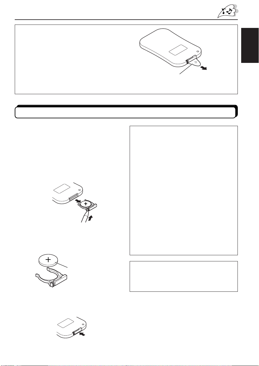
Before using the remote controller:
When you use the remote controller for the
first time, pull out the insulation sheet as
illustrated to the right.
• Aim the remote controller directly at the
remote sensor on the color monitor. Make
sure there is no obstacle in between.
• Do not expose the remote sensor to strong
light (direct sunlight or artificial lighting).
Replacing the battery
When the controllable range or effectiveness
of the remote controller decreases, replace
the battery.
1. Remove the battery holder.
While pushing in the lock using a ball-point
pen or a similar tool (1), pull out the
battery holder in the direction indicated by
the arrow (2).
(back side)
2
1
2. Replace the battery.
Slide a new battery into the holder with
the + side facing upwards so that the
battery is fixed in the holder.
(back side)
ENGLISH
Pull out
Insulation sheet
(The battery has been installed when shipped
from the factory.)
WARNING:
• Store the battery in a place which children
cannot reach.
If a child accidentally swallows the battery,
immediately consult a doctor.
• Do not recharge, short, disassemble or heat
the battery or dispose of in a fire.
Doing any of these things may cause the
battery to give off heat, crack or start a fire.
• Do not leave the battery with other metallic
materials.
Doing this may cause the battery to give off
heat, crack or start a fire.
• When throwing away or saving the battery,
wrap in tape and insulate; otherwise, it may
cause the battery to give off heat, crack or
start a fire.
• Do not poke the battery with tweezers or
similar tools.
Doing this may cause the battery to give off
heat, crack or start a fire.
Lithium coin battery
(product number:
CR2025)
3. Return the battery holder.
Insert the battery holder again pushing it
until you hear a clicking sound.
(back side)
CAUTION:
DO not leave the remote controller in a place
(such as dashboard) exposed to direct sunlight
for a long time. Otherwise, it may be damaged.
7
Page 28

BASIC OPERATIONS
;
;
;
;
;
;
;
;
;
;
;
;
;
;
;
;
;
;
;
;
;
;
;
;
;
;
;
;
;
VIDEO 1
Preparation
Before operating the monitor system, make sure that all external components are
correctly connected and installed.
ENGLISH
2
1
3
3
Monitor
1, 2
1
Turn on the power.
Monitor Remote
2
MODE
Monitor Remote
• When KV-C10 is not connected: • When KV-C10 is connected:
AV 1
AV 2
Select the input source.
Each time you press the button, the input source changes
as follows:
TV
VIDEO 1
MONITOR
;;;;;;
;;;;;;
MODE
;;;;;;
;;;;;;
;;;;;;
;;;;;;
;;;;;;
;;;;;;
;;;;;;
MENU
;;;;;;
;;;;;;
;;;;;;
;;;;;;
;;;;;;
;;;;;;
;;;;;;
;;;;;;
;;;;;;
;;;;;;;;;;;;;;;;;
;;;;;;;;;;;;;;;;;
Remote
TV TUNER
TV
CH
;;;;;;;;;;;
;;;;;;;;;;;
;;;;;;;;;;;
;;;;;;;;;;;
SKIP
A.MEMO
;;;;;;;;;;;
VOCAL
R F
;;;;;;;;;;;
;;;;;;;;;;;
;;;;;;;;;;;
;;;;;;;;;;;
H/P
VOLUME
CALL
VIDEO 2
AV1: PAL
MODE
MENU
Ex. When “AV 1” is selected
Ex. When “VIDEO 1” is selected
3
Select the video format—PAL or NTSC, while
the indication of the video format is still on the
Monitor
8
Remote
screen.
Each time you press the button, the video format
alternates between PAL (initial setting) and NTSC. Select
whichever matches to the incoming signals.
Note:
When not using the KV-C10: You can preset the video format
separately for “AV 1” and “AV 2.”
Page 29

4
Play back the external component.
To operate the external components, refer to the manuals for the connected
components.
5
Select the external component and adjust the volume on the car
receiver.
ENGLISH
To check the current input source
On the monitor: Press the Power button ( ) once.
On the remote: Press the MODE button once.
The on-screen display appears for about 5 seconds.
Monitor Remote
MODE
To turn off the power
On the monitor: Press and hold the Power button ( ).
On the remote: Press the Power On/Standby button (
) .
Monitor Remote
When you use JVC FM modulator KS-IF200
Selecting the RF signals to the receiver
You can listen to playback sounds from the external component through the receiver even if
it is equipped with no line input.
• Refer also to the instructions of KS-IF200.
When KV-C10 is connected:
Press the RF button on the remote controller.
Each time you press the button, “RF ON” and “RF OFF” alternate and the sounds you hear
through the car speakers change accordingly.
RF ON : Select to listen to the sound of the external component.
RF OFF : Select to listen to the radio (through the receiver).
9
Page 30

ADJUSTMENTS
;
;
;
;
;
;
;
;
;
;
;;;;;;;;;;;;
;
;
;
;
;
;
;
;
;
;
;
;
;
;
;
;
;
;
;
;
;
;
;
;
;
;
;
;;;;;;;;;;;;
;
;
;
Using the Menu
You can make your own adjustments using the Menu.
• For the adjustable items, see the next page.
ENGLISH
Basic procedure
1, 2, 4
1
Monitor Remote
2
Monitor Remote
3
Monitor
MENU
MENU
1, 2, 4
3
MONITOR
;;;;;;;
MODE
;;;;;;;
;;;;;;;
;;;;;;;
;;;;;;;
;;;;;;;
;;;;;;;
;;;;;;;
;;;;;;;
MENU
;;;;;;;
;;;;;;;
;;;;;;;
;;;;;;;
;;;;;;;
;;;;;;;
;;;;;;;
;;;;;;;
;;;;;;;;;;;;;;;;
;;;;;;;;;;;;;;;;
;;;;;;;;;;;;;;;;
TV TUNER
;;;;;;;;;;
;;;;;;;;;;
;;;;;;;;;;
;;;;;;;;;;
;;;;;;;;;;
SKIP
;;;;;;;;;;
VOCAL
;;;;;;;;;;
;;;;;;;;;;
;;;;;;;;;;
;;;;;;;;;;
TV
CH
H/P
VOLUME
A.MEMO
R F
CALL
Remote
Call up the Menu.
Cursor
COLOR
BRIGHT
TINT
DIMMER
FORMAT
RESET
MODE
MENU
Select an item you want to adjust.
Each time you press the button, the cursor moves to the
next item.
10
3
Adjust the level of the selected item (or select
an appropriate setting for the selected item).
• When “RESET” is selected in the above step, the Color,
Brightness, and Tint settings are reset.
Monitor Remote
TINT 32
Ex: When adjusting Tint
MODE
MENU
Activated button is
highlighted.
Page 31

4
BRIGHT 32
TINT 32
DIMMER
OFF ON
MENU
Exit from the Menu.
• Press the button repeatedly until the Menu is erased.
Monitor Remote
Adjustable items on the menu
COLOR
Appears only for
NTSC video format
Note:
Menu goes off if no operation is done for about 5 seconds.
BRIGHT
TINT
DIMMER
FORMAT
RESET
MODE
MENU
ENGLISH
COLOR : Adjust the color of the picture—lighter or
darker.
• Adjustable range: 0 to 63
• Initial level: 32
BRIGHT : Adjust this if the picture is too bright or too
dark.
• Adjustable range: 0 to 63
• Initial level: 32
TINT : Adjust this if the human skin color is unnatural.
• Adjustable range: 0 to 63
• Initial level: 32
Note:
This can be shown and adjusted when the video
format is NTSC.
DIMMER : Activate the dimmer if the inside of the car is
too bright to view the picture on the screen.
• Selectable settings: ON/OFF
• Initial setting: OFF
COLOR 32
CONTINUED ON THE NEXT PAGE
11
Page 32
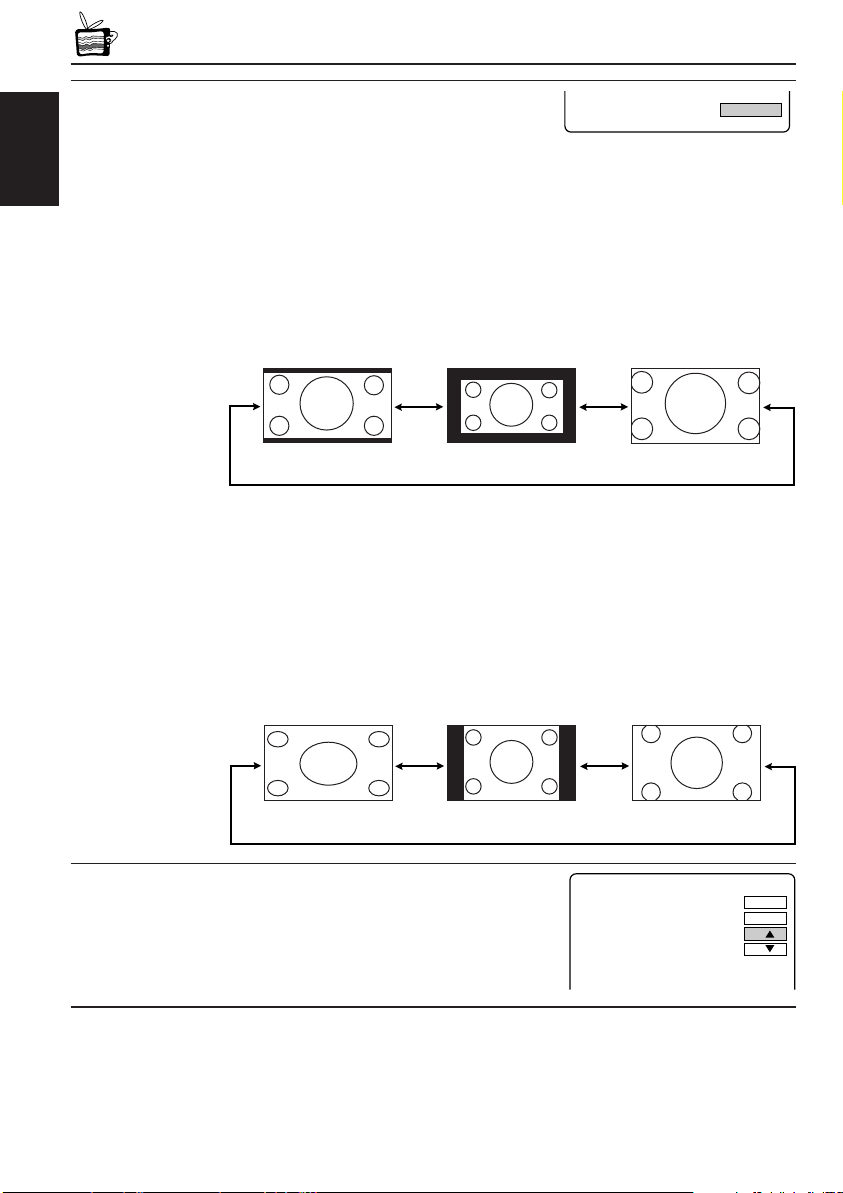
FORMAT : Select an appropriate display size.
FORMAT FULL
MODE
MENU
COLOR
BRIGHT
TINT
RESET
32
32
32
• Selectable settings: FULL/NORMAL/ZOOM
• Initial setting: FULL
ENGLISH
When viewing 16:9 video signals:
FULL: Pictures are fully shown on the screen.
• The black bars will be shown both at the top and the bottom of
the screen.
NORMAL: Pictures are shown at the center of the screen.
ZOOM: Pictures are enlarged on the screen so that no black bars will be
shown on the screen. (The entire picture cannot be shown on
the screen.)
FULL
NORMAL
ZOOM
When viewing 4:3 video signals:
FULL: Pictures are enlarged horizontally and are fully shown on the
screen.
NORMAL: Pictures are shown at the center of the screen.
• The black bars will be shown at the left and right sides of the
screen.
ZOOM: Pictures are enlarged on the screen so that no black bars will be
shown on the screen. (The entire picture cannot be shown on
the screen.)
FULL
RESET : Reset the Color, Brightness, and Tint levels
to the initial settings.
12
NORMAL
ZOOM
Page 33

MAINTENANCE
To prevent damage to the exterior
• Do not apply pesticides, benzine, thinner or other volatile substances to the unit.
The cabinet surface primarily consists of plastic materials.
• Do not wipe with benzine, thinner or similar substances because this will results in
discoloration or removal of the paint.
• When a cloth with a cleansing chemical is used, follow the caution points.
– Do not leave the unit in contact with rubber or vinyl products for long periods of time.
– Do not use cleansers which have polishing granules because this could damage the
surface of the unit.
Clean off dirt by wiping lightly with a soft cloth
When the unit is very dirty, wipe with a well-wrung cloth dipped in a kitchen cleanser (neutral)
thinned by water and then go over the same surface with a dry cloth.
(Since there is the possibility of water drops getting inside of the unit, do not directly apply
cleanser to the surface.)
Caution:
If water drops or similar wet substances get inside of the monitor via the liquid crystal panel surface,
it may cause a malfunction.
ENGLISH
13
Page 34
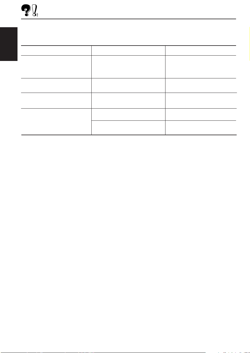
TROUBLESHOOTING
What appears to be trouble is not always serious. Check the following points before calling a
service center.
ENGLISH
Symptoms
• Colored spots (red, blue and
green) appear on the screen.
• No picture appears and sound
is not heard.
• Picture shakes vertically or
colors are abnormal.
• Remote controller does not
work.
Causes
This is a characteristic of liquid
crystal panels and is not a
malfunction.
Correct input mode is not
selected.
The video format (NTSC/PAL) is
not correct.
The battery has lost its charge.
Remote sensor is exposed to
strong light.
Remedies
See “Note” on page 15.
Select the correct input mode.
Select the correct video format.
Install a new battery.
Do not expose the remote
sensor to strong light.
14
Page 35

SPECIFICATIONS
WIDE COLOR MONITOR
Display:
6.5 inch Liquid crystal panel
Number of Pixel:
280 800 pixels
×
(400 vertical
Drive Method:
TFT (Thin Film Transistor) active matrix
format
Dimensions (W × H × D):
184 mm × 124 mm × 31 mm
(7-1/4” × 4-15/16” × 1-1/4”)
including Shroud
Mass: 325 g (0.52 lbs) including Shroud
234 horizontal × 3)
MONITOR CONNECTION
UNIT
Input
Video: RCA pin × 2 circuits
1 V(p-p), 75 Ω
Audio: RCA pin × 2 circuits
0.5 V(rms)
Tuner: 8-pin DIN connector
(only for JVC’s KV-C10)
Output
Display:
13-pin DIN connector
Video: RCA pin × 1 circuit
1 V(p-p), 75 Ω
Audio: RCA pin × 1 circuit
0.5 V(rms)
Dimensions (W × H × D):
108.5 mm × 28.5 mm × 78 mm
(4-5/16” × 1-1/8” × 3-1/8”)
excluding projections
Mass: 160 g (0.36 lbs)
GENERAL
Power Requirement
Operating Voltage:
DC 14.4 V (11 V to 16 V allowance)
Grounding System:
Negative ground
Allowable Operating Temperature:
0°C to +40°C (32°F to 104°F)
Allowable Storage Temperature:
–20°C to +80°C (–4°F to 176°F)
ACCESSORIES
Mounting spacer × 1
Shroud × 1
System cord × 1
Power cord × 1
Remote controller (with the battery) × 1
Paper pattern × 1
Design and specifications are subject to change
without notice.
Note:
The liquid crystal panel is built with very high
precision technology and has at least 99.99%
effective image pixels. Be aware that on 0.01%
of the panel there may be missing pixels or
constantly lit pixels.
ENGLISH
15
Page 36

http://www.jvcmobile.c
om
Visit us on-line for
Technical Support & Customer Satisfaction Survey.
US RESIDENTS ONLY
VICTOR COMPANY OF JAPAN, LIMITED
EN, SP, FR
© 2003 VICTOR COMPANY OF JAPAN, LIMITED
0303MNMMDWPUN
JVC
Page 37

KV-MH6500
JVC
AV1
VIDEO
AV2
L AUDIO R
L AUDIO R
VIDEO
AV OUT
R AUDIO L
VIDEO
13 PIN
TO MONITOR
8 PIN
TO TV TUNER
INPUT 2
INPUT 1
;
;
;
;
;
;
;
;
;
;
;
;
;
;
;
;
;
TV TUNER
TV
CH
H/P
VOLUME
MONITOR
MODE
MENU
CALL
VCP
R F
VOCAL
SKIP
A.MEMO
RM-RK500
Installation/Connection Manual
Manual de instalación/conexión
Manuel d’installation/raccordement
LVT0989-002A
[J]
0303MNMMDWPUN
EN, SP, FR
ENGLISH
WARNING
Installation requires some special knowledge.
Do not install the monitor system yourself. Consult a dealer
having special knowledge of this kind for safe and reliable
installation.
• DO NOT INSTALL THE MONITOR IN A LOCATION WHICH
OBSTRUCTS DRIVING, VISIBILITY OR WHICH IS PROHIBITED
BY APPLICABLE LAWS AND REGULATIONS.
If the monitor is installed in a location which obstructs forward
visibility or operation of the air bag or other safety equipment or
which interferes with operation of the vehicle, it may cause an
accident.
• NEVER USE BOLTS OR NUTS FROM THE VEHICLE’S
SAFETY DEVICES FOR INSTALLATION.
If bolts or nuts from the steering wheel, brakes or other safety
devices are used for installation of the monitor, it may cause an
accident.
• ATTACH THE WIRES CORRECTLY.
If the wiring is not correctly performed, it may cause a fire or an
accident. In particular, be sure to run and secure the lead wire
so that it does not get tangled with a screw or the moving portion
of a seat rail.
• USE WITH DC 12 V NEGATIVE GROUND VEHICLES.
This monitor system is only for use in a DC 12 V negative ground
vehicle.
It cannot be used in large trucks or diesel vehicles which are DC
24 V vehicles.
If it is used in the wrong type of vehicle, it may cause a fire or
accident.
• To prevent short circuits, we recommend that you disconnect
the battery’s negative terminal and make all electrical connections
before installing the unit. If you are not sure how to install this
unit correctly, have it installed by a qualified technician.
• Avoid installing the monitor connection unit in the following
places
– Where it would hinder your safe driving.
– Where it would be exposed to direct sunlight or heat directly
from the heater or placed in an extremely hot place.
– Where it would be subject to rain, water splashes or excessive
humidity.
– Where it would be subject to dust.
– Where it would be positioned on an unstable place.
– Where it could damage the car’s fittings.
– Where proper ventilation would not be maintained, such as
under a floor mat.
CAUTION
Since there may be legal regulations defining the permissible
installation locations for the color monitor which differ by country
or by state, be sure to install the color monitor in a location
complying with any such laws.
ADVERTENCIA
La instalación requiere cierto conocimiento especial.
No instale el sistema del monitor por sí mismo. Para una
instalación segura y confiable, consulte con un
concesionario que tenga conocimientos especiales en
esta área.
• NO INSTALE EL MONITOR EN UN LUGAR QUE IMPIDA EL
MANEJO O LA VISIBILIDAD, NI DONDE LOS PROHIBAN LAS
LEYES Y REGLAMENTOS APLICABLES.
Si el monitor se instala en un lugar que obstruye la visibilidad
hacia adelante o la operación de una bolsa de aire u otro equipo
de seguridad, o que interfiere con la operación del vehículo,
cerca de la palanca de cambios o pedal del freno por ejemplo,
podrá causarse un accidente.
• NUNCA UTILICE PERNOS O TUERCAS DE LOS
DISPOSITIVOS DE SEGURIDAD DEL VEHÍCULO PARA
HACER LA INSTALACIÓN.
Si los pernos o tuercas del volante, frenos u otros dispositivos
de seguridad se utilizan para instalar el monitor podrá causarse
un accidente.
• REALICE EL CABLEADO CORRECTAMENTE.
Si no se hace bien el cableado puede producirse un incendio
o un accidente. En particular, asegúrese de instalar el cable
conductor para que éste no quede enredado en un tornillo ni
en la parte móvil del raíl del asiento.
• UTILICE EL MONITOR EN VEHÍCULOS DE 12 V CC CON
PUESTA A TIERRA NEGATIVA.
Este monitor ha sido diseñado para ser utilizado solamente en
vehículos de 12 V CC con puesta a tierra negativa.
No puede utilizarse en camiones grandes ni vehículos diesel
de 24 V CC.
Si se utiliza en el tipo equivocado de vehículo se puede causar
un incendio o accidente.
• Para evitar cortocircuitos, se recomienda desconectar el
terminal negativo de la batería y realizar todas las conexiones
eléctricas antes de instalar la unidad. Si tiene dudas sobre cómo
realizar la instalación correctamente, déjela en manos de un
técnico cualificado.
• Evite instalar la unidad de conexión del monitor en los
siguientes lugares:
– Donde pueda constituir un obstáculo para la conducción.
– Donde pueda quedar expuesto a la luz solar directa o al calor
directo de un calefactor, o en un lugar muy caliente.
– Donde pueda mojarse debido a la lluvia, etc., o en un lugar
excesivamente húmedo.
– En un lugar polvoriento.
– En un sitio inestable.
– Donde pueda producir daños en los herrajes del automóvil.
– En lugares donde no pueda obtenerse una ventilación
adecuada, como debajo de la alfombra del piso.
PRECAUCION
Dependiendo de los estados, pueden haber reglamentos
locales que determinan los lugares de instalación permisibles
para el monitor de color; por lo tanto, asegúrese de instalar el
monitor en un sitio que cumpla con tales reglamentos.
FRANÇAISESPAÑOL
AVERTISSEMENT
L’installation nécessite certaines connaissances
spéciales.
N’installez pas le moniteur vous-même. Consultez un
revendeur possédant les connaissances spéciales
nécessaires pour une installation correcte et sûre.
• N’INSTALLEZ PAS LE MONITEUR DANS UN ENDROIT QUI
GÊNE LA CONDUITE, LA VISIBILITÉ OU QUI EST INTERDIT
PAR LE CODE DE LA ROUTE ET LES RÈGLEMENTS.
Si le moniteur était installé à un emplacement gênant la visibilité
avant, ou le déploiement du sac à air, et autres dispositifs de
sécurité, ou à un emplacement gênant pour la conduite du
véhicule, comme près du levier des vitesses ou de la pédale du
frein, cela risquerait de provoquer des accidents.
• NE JAMAIS UTILISER POUR L’INSTALLATION DES
BOULONS OU DES ÉCROUS PROVENANT DES DISPOSITIFS
DE SÉCURITÉ DU VÉHICULE.
Si l’on utilisait pour l’utilisation du moniteur des boulons et des
écrous cannibalisés du volant, des freins ou autres dispositifs
de sécurités, cela risquerait de provoquer des accidents.
• ATTACHER LES CORDONS CORRECTEMENT.
Si le câblage n’est pas exécuté correctement, cela risque de
provoquer un incendie ou autre accident. Veiller, en particulier,
à tirer et attacher les fils en sorte qu’ils me s’accrochent pas à
une vis ou ne se coincent dans les parties mobiles des rails des
sièges.
• USAGE SUR LES VÉHICULES DE 12 V CC AVEC NÉGATIF
À LA MASSE.
Ce moniteur ne peut être utilisé que sur les véhicules de 12 V CC
avec négatif à la masse.
Il ne peut pas être utilisé sur les gros camions ou les véhicules
diesel de 24 V CC.
S’il était utilisé sur un type de véhicule inadéquat cela risquerait
de provoquer un incendie ou autres accidents.
• Pour éviter les courts-circuits,
déconnectiez la borne négative de la batterie et réalisiez toutes
les connexions électriques avant d’installer l’appareil. Si vous
n’êtes pas sûr de savoir comment installer cet appareil
correctement, faites-le installer par un technicien qualifié.
• Évitez d’installer l’unité de connexion du moniteur dans
les endroits suivants:
– Où il peut gêner la conduite de la voiture.
– Où il est exposé à la lumière directe du soleil, à la chaleur
directe du chauffage ou placé dans un endroit très chaud.
– Où il est sujet à la pluie, aux éclaboussures ou à une humidité
excessive.
– Où il est sujet à la poussière.
– Où il est positionné dans un endroit instable.
– Où il peut endommager les accessoires de la voiture.
– Où une ventilation correcte ne peut pas être maintenue,
comme sous un tapis de sol.
ATTENTION
Il peut y avoir des réglementations définissant les
emplacements d’installation autorisés pour un moniteur couleur
et celles-ci peuvent varier d’une région à l’autre. Assurez-vous
d’installer le moniteur dans un endroit conforme à ces lois.
nous recommandons que vous
Parts list for installation and connection
The following parts are provided with this unit.
After checking them, please set them correctly.
Wide color monitor (center unit and shroud)
Monitor color de pantalla ancha
(unidad central y refuerzo)
Moniteur couleur à écran large
(unité centrale et socle de montage au plafond)
Lista de piezas para instalación y conexión
Con esta unidad se suministran las siguientes piezas.
Después de inspeccionarlas, colóquelas correctamente.
Mounting spacer
Espaciador de montaje
Entretoise de montage
System cord (3 m) (9.8 ft)
Cordón del sistema (3 m) (9.8 pies)
Cordon de système (3 m) (
9.8
pieds)
– 1 –
Paper pattern
Patrón de papel
Modèle en papier
Power cord
Cordón de alimentación
Cordon d’alimentation
Liste des pièces pour l’installation et
raccordement
Les pièces suivantes sont fournies avec cet appareil.
Après vérification, veuillez les placer correctement.
Monitor connection unit
Unidad de conexión del monitor
Unité de connexion du moniteur
;;;;
;;;;
;;;;
;;;;
;;;;
;;;;
;;;;
;;;;
;;;;
;;;;;;;;;
;;;;;;;;;
;;;;;;;;;
;;;;;;
;;;;;;
;;;;;;
;;;;;;
;;;;;;
Remote controller
with a battery (CR2025) installed
Unidad de control remote
con una pila instalada (CR2025)
Télécommande
avec une pile en place (CR2025)
Page 38

INSTALLATION
AV1
VIDEO
AV2
L AUDIO R
L AUDIO R
VIDEO
AV OUT
R AUDIO L
VIDEO
13 PIN
TO MONITOR
8 PIN
TO TV TUNER
INPUT 2
INPUT 1
1
2
3
4
AV1
VIDEO
AV2
L AUDIO R
L AU R
VIDEO
AV OUT
R AUDIO L
VIDEO
13 PIN
TO MONITOR
8 PIN
TO TV TUNER
INPUT 2
INPUT 1
6
5
• The following illustration shows a typical installation. However,
you should make adjustments corresponding to your specific
car. If you have any questions or require information regarding
installation kits, consult your JVC car audio dealer or a company
supplying kits.
INSTALACION
• La siguiente ilustración muestra una instalación típica. Sin
embargo usted deberá efectuar los ajustes correspondientes
a su automóvil. Si tiene alguna pregunta o necesita información
acerca de las herramientas para instalación, consulte con su
concesionario de JVC de equipos de audio para automóviles o
a una compañía que suministra tales herramientas.
INSTALLATION
•
L’illustration suivante est un exemple d’installation typique.
Cependant, vous devez faire les ajustements correspondant à votre
voiture particulière. Si vous avez des questions ou avez besoin
d’information sur des kits d’installation, consulter votre revendeur
d’autoradios JVC ou une compagnie d’approvisionnement.
Mounting the color monitor
It is recommended to have the monitor system installed by
a qualified technician.
Before mounting the monitor to the headrest:
• Perform the required external connections first.
• Using the supplied paper pattern, mark the area to be cut out
of the headrest, then carefully cut it.
Mark the area to be cut out, and carefully cut it.
Marque el área que se va a recortar en el
reposacabezas, y corte con cuidado.
Marquez la zone à couper et coupez-la avec
précaution.
Paper pattern
Patrón de papel
Modèle en papier
Headrest
Reposacabezas
Repose-tête
Montaje del monitor de color
Se recomienda que el sistema de monitor sea instalado por
un técnico cualificado.
Antes de instalar el monitor en el echo reposacabezas:
Efectúe primero las conexiones externas requeridas.
•
• Utilizando el patrón de papel suministrado, marque el área
que se va a recortar en el reposacabezas, y corte con cuidado.
Mounting spacer (if required to fit the shroud to the rear surface of the headrest)
Installation plate (not supplied)
Placa de instalación (no suministrada)
(not supplied)
Plaque d’installation (non fournie)
System cord (from the monitor connection unit)
Cordón del sistema (desde la unidad de conexión del
monitor)
Cordon de système (à partir de l’unité de connexion)
Espaciador de montaje (si es necesario acoplar el refuerzo a la superficie trasera del
reposacabezas)
Entretoise de montage S’il est nécessaire de monter le socle de montage sur la surface
arrière du repose-tête.
Shroud
Refuerzo
Socle de montage au plafond
Montage du moniteur couleur
Il est recommandé de faire installer le système de moniteur
par un technicien qualifié.
Avant de fixer le moniteur au repose-tête:
• Réalisez d’abord les connexions extérieures nécessaires.
• En utilisant le modèle en papier fourni, marquez la zone à couper
sur le repose-tête, puis coupez-la avec précaution.
Screws (not supplied)
Tornillos (no suministrados)
Vis (non fournis)
Center unit
Unidad central
Unité centrale
* Attached to the center
unit when purchased.
* Fijado a la unidad
central en el momento
de la compra.
* Fixées à l’unité centrale
à l’achat.
*
• For safety, use neither a sharp-pointed screw nor a long screw which will protrude more than 5 mm (1/4”)
from the back of the installation plate.
• Para fines de seguridad, no utilice tornillos de punta afilada ni tornillos que sobresalgan mas de 5 mm
(1/4”) del lado trasero de la placa de instalación.
• Pour des raisons de sécurité, n’utilisez jamais une vis pointue ni une vis longue qui dépasse de 5 mm
(1/4 po.) de l’arrière de la plaque d’installation.
VCR or DVD/CD receiver, etc.
VCR o receptor con DVD/CD, etc.
Magnétoscope, recepteur DVD/CD, etc.
Monitor connection unit
Unidad de conexión del monitor
Unité de connexion du moniteur
How to detach the center unit from the shroud
Cómo separar la unidad central del refuerzo
Comment détacher l’unité centrale du socle de
montage
Release the lock levers by inserting something like a card
into the gap between the center unit and the shroud, then
remove the center unit.
Libere las palancas de bloqueo insertando un objeto tal
como una tarjeta o similar entre la unidad central y el
refuerzo, y luego retire la unidad central.
Libérez les leviers de verrouillage en
insérant quelque chose comme une
carte dans l’espace entre l’unité
centrale et le socle de montage, puis
retirez l’unité centrale.
CAUTION / PRECAUCION / ATTENTION:
• Take preventative measures to avoid unexpected disconnection of the cord and damage to the cord by being caught
somewhere. This trouble may happen while adjusting the headrest position or while moving or reclining the seat.
• Tome las medidas de prevención necesarias para evitar que el cordón se desconecte imprevistamente y que quede
enganchado en algún lugar. Esto podría producirse al mover el reposacabezas, o al mover o reclinar el asiento.
• Prenez des mesures préventives pour éviter que le cordon soit déconnecté accidentellement ou coincé quelque part—
Cela peut se produire quand vous bougez le repose-tête, ou quand vous bougez ou inclinez le siège.
Monitor connection unit / Unidad de conexión del monitor / Unité de connexion du moniteur
Front
Lado delantero
Avant
1 AV 2 (INPUT 2) jacks
• VIDEO/AUDIO L (left)/AUDIO R (right)
2 AV 1 (INPUT 1) jacks
• VIDEO/AUDIO L (left)/AUDIO R (right)
3 AV OUT jacks
• VIDEO/AUDIO L (left)/AUDIO R (right)
4 Power Supply connector
5 TO MONITOR (13 PIN) connector
6 TO TV TUNER (8 PIN) connector
Back
Lado trasero
Arrière
1 Jacks AV 2 (INPUT 2)
• VIDEO/AUDIO L (izquierdo)/AUDIO R (derecho)
2 Jacks AV 1 (INPUT 1)
• VIDEO/AUDIO L (izquierdo)/AUDIO R (derecho)
3 Jacks AV OUT
• VIDEO/AUDIO L (izquierdo)/AUDIO R (derecho)
4 Conector de la fuente de alimentación
5 Conector TO MONITOR (13 clavijas)
6 Conector TO TV TUNER (8 clavijas)
– 2 –
Side
Lateral
Côté
Prises AV 2 (INPUT 2)
1
• VIDEO/AUDIO L (gauche)/AUDIO R (droit)
2
Prises AV 1 (INPUT 1)
• VIDEO/AUDIO L (gauche)/AUDIO R (droit)
3
Prises AV OUT
• VIDEO/AUDIO L (gauche)/AUDIO R (droit)
4
Connecteur d’alimentation
5
Connecteur TO MONITOR (13 PIN)
6
Connecteur TO TV TUNER (8 PIN)
Page 39
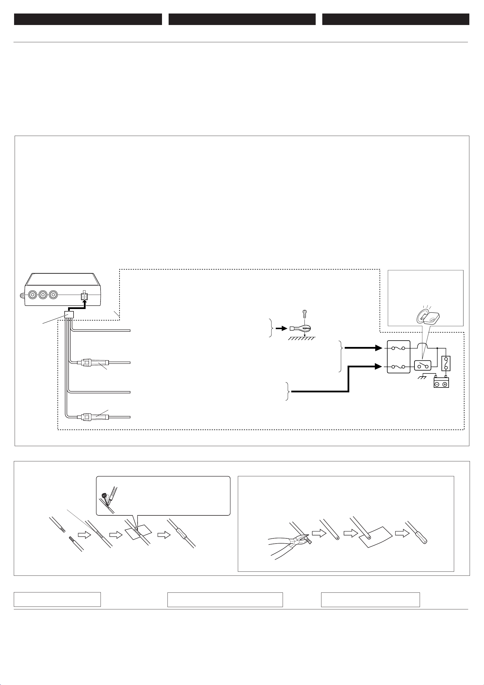
250V 5A250V 1A
4
1
2
3
ENGLISH ESPAÑOL FRANÇAIS
ELECTRICAL CONNECTIONS
To prevent short circuits, we recommend that you disconnect the
battery’s negative terminal and make all electrical connections
before installing the unit. If you are not sure how to install this unit
correctly, have it installed by a qualified technician.
Note:
This unit is designed to operate on 12 V DC, NEGATIVE ground
electrical systems. If your vehicle does not have this system, a
voltage inverter is required, which can be purchased at JVC car
audio dealers.
• Replace the fuse with one of the specified ratings. If the fuse
blows frequently, consult your JVC car audio dealer.
CONEXIONES ELECTRICAS
Para evitar cortocircuitos, recomendamos que desconecte el
terminal negativo de la batería y que efectúe todas las conexiones
eléctricas antes de instalar la unidad. Si usted no está seguro de
cómo instalar correctamente la unidad, hágala instalar por un
técnico cualificado.
Nota:
Esta unidad está diseñada para funcionar con 12 V de CC, con
sistemas eléctricos de masa NEGATIVA. Si su vehículo no
posee este sistema, será necesario un inversor de tensión, que
puede ser adquirido en los concesionarios de JVC de equipos
de audio para automóviles.
• Reemplace el fusible por uno con la corriente especificada. Si
el fusible se quemase frecuentemente, consulte con su
concesionario car audio de JVC.
Typical Connections / Conexiones tipicas / Raccordements typiques
Before connecting: Check the wiring in the vehicle carefully.
Incorrect connection may cause serious damage to this unit.
The leads of the power cord and those of the connector from the
car body may be different in color.
7 Power supply connection
1
Connect the colored leads of the power cord in the following
sequence.
1 Black: ground
2 Yellow: to car battery (constant 12 V)
3 Red: to an accessory terminal
4 Blue: to remote control lead of the external component
(such as KS-IF200).
2
Finally connect the wiring harness to the unit.
Antes de la conexión: Verifique atentamente el conexionado
del vehículo. Una conexión incorrecta podría producir daños
graves en la unidad.
Los conductores del cordón de alimentación y de los conectores
procedentes de la carrocería del vehículo podrían ser diferentes
en color.
7 Conexión de la fuente de alimentación
1
Conecte los conductores de color del cordón de alimentación
en la secuencia siguiente.
1 Negro: a tierra
2 Amarillo: a la batería del automóvil (12 V constantes)
3 Rojo: a un terminal de accesorio
4 Azul: para el conductor del controlador remoto del
componente externo (como por ejemplo KS-IF200).
2
Por último, conecte el cable de alimentación a la unidad.
RACCORDEMENTS ELECTRIQUES
Pour éviter tout court-circuit, nous vous recommandons de
débrancher la borne négative de la batterie et d’effectuer tous les
raccordements électriques avant d’installer l’appareil. Si l’on n’est
pas sûr de pouvoir installer correctement cet appareil, le faire
installer par un technicien qualifié.
Remarque:
Cet appareil est conçu pour fonctionner sur des sources de courant
continu de
ce type d’alimentation, il vous faut un convertisseur de tension,
que vous pouvez acheter chez un revendeur d’autoradios JVC.
•
Remplacer le fusible par un de la valeur précisée. Si le fusible
saute souvent, consulter votre revendeur d’autoradios JVC.
Avant de commencer la connexion:
câblage du véhicule. Une connexion incorrecte peut endommager
sérieusement l’appareil.
Les fils du cordon d’alimentation et ceux du connecteur provenant
de la voiture peuvent être de couleur différente.
7 Connexion de l’alimentation
1
Connectez les fils de couleur du cordon du plafonnier dans
l’ordre suivant.
2
Finalement, connectez le faisceau de fils à l’appareil.
12 V à masse NEGATIVE
1
Noir: à la masse
2
Jaune: à la batterie de la voiture (12 V constant)
3
Rouge: à la prise accessoire
4
Bleu: au fil de télécommande de l’appareil extérieur (tel
que le KS-IF200).
. Si votre véhicule n’offre pas
Vérifiez attentivement le
2
Black / Negro /
1
Yellow*
Amarillo*
Jaune*
Red
Rojo
Rouge
Blue
Azul
Bleu
1
1
1
Noir
5 A fuse
Fusible de 5A
Fusible 5 A
1 A fuse
Fusible de 1A
Fusible 1 A
*1: Before checking the operation of this unit prior to installation, this lead must be connected, otherwise
power cannot be turned on.
*1: Antes de comprobar el funcionamiento de esta unidad previa a de la instalación, es necesario conectar
este cable, de lo contrario no se podrá conectar la alimentación.
*1: Pour vérifier le fonctionnement de cet appareil avant installation, ce fil doit être raccordé, sinon l’appareil ne
peut pas être mis sous tension.
To metallic body or chassis of the car
A un cuerpo metálico o chasis del automóvil
Vers corps métallique ou châssis du véhicule
To a live terminal in the fuse block connecting to the car battery (bypassing the ignition switch)
A un terminal activo del bloque de fusibles conectado a la batería del automóvil (desviando
el interruptor de encendido)
A une borne sous tension du porte-fusible connectée à la batterie de la voiture (en dérivant
l’interrupteur d’allumage)
To an accessory terminal in the fuse block
A un terminal accesorio del bloque de fusibles
Vers borne accessoire du porte-fusible
To remote lead of the external component (such as KS-IF200)
Para el conductor del controlador remoto del componente externo (como por ejemplo KS-IF200)
Au fil de télécommande de l’appareil extérieur (tel que le KS-IF200)
2
*
2
*
Ignition switch
Interruptor de encendido
Interrupteur d’allumage
Fuse block
Bloque de fusibles
Porte-fusible
*2Not included with this unit.
*2No suministrado con esta unidad.
*2Non fourni avec cet appareil.
Connecting the leads / Conexión de los conductores / Raccordement des fils
Twist the core wires when
connecting.
Retuerza los alambres de alma
para conectarlos.
Torsader les âmes des fils en les
raccordant.
Solder the core wires to connect them securely.
Suelde los alambres de alma para conectarlos
con firmeza.
Soudez les âmes des fils pour les raccorder
entre eux de façon sûre.
TROUBLESHOOTING
• The fuse blows.
* Are the red and black leads connected correctly?
• Power cannot be turned on.
* Is the yellow lead connected?
• Picture does not come on screen.
* Is the correct input selected?
• Picture does not appear clearly.
* Is the color monitor installed at the right angle?
LOCALIZACION DE AVERIAS
• El fusible se quema.
* ¿Están los conductores rojo y negro correctamente conectados?
• No es posible conectar la alimentación.
* ¿Está el cable amarillo conectado?
• La imagen no aparece en la pantalla.
* ¿Se ha seleccionado la entrada correcta?
• La imagen no aparece con claridad.
* ¿Está el monitor de color instalado en un ángulo correcto?
– 3 –
CAUTION / PRECAUCION / PRECAUTION:
• To prevent short-circuit, cover the terminals of the UNUSED leads with insulating
tape.
• Para evitar cortocircuitos, cubra los cables NO UTILIZADOS con cinta aislante.
• Pour éviter les court-circuits, couvrir les bornes des fils qui ne sont PAS utilisés
avec de la bande isolante.
EN CAS DE DIFFICULTÉS
• Le fusible saute.
Les fils rouge et noir sont-ils racordés correctement?
*
• L’appareil ne peut pas être mise sous tension.
*
Le fil jaune est-elle raccordée?
• Aucune image n’apparaît sur l’écran.
*
L’entrée correcte est-elle choisie?
• L’image n’apparaît pas clairement.
Le moniteur couleur est-il installé avec un angle correct?
*
Page 40

HEADPHONE
ANTENNA INPUT INPUT 2
INPUT 1
12
234
VIDEO L R
VIDEO
CONTAUDIO
L RAUDIOVIDEO1
OUTPUT
RL
VIDEO TO DISPLAY VOCAL POWER
SUPPLY
AUDIO
ATT
ATT
CONNECTING THE EXTERNAL
CONEXION DE LOS COMPONENTES
CONNEXION DES APPAREILS
COMPONENTS
Connect the monitor to TO MONITOR jack using the system cord
supplied with the unit.
The monitor connection unit provides 2 input circuits and 1 output
circuit. Connect one or two playback sources to AV 1 (INPUT 1)
and/or AV 2 (INPUT 2) and connect reproducing components, such
as a car receiver, to AV OUT.
EXTERNOS
Conecte el monitor al jack TO MONITOR. Utilice el cable
prolongador suministrado con la unidad cuando la longitud del
cable del monitor no sea suficiente para la conexión.
Esta unidad de conexión del monitor posee 2 circuitos de entrada
y 1 circuito de salida. Conecte uno o dos fuentes de reproducción
a AV 1 (INPUT 1) y/o AV 2 (INPUT 2) y conecte los componentes
de reproducción, como un receptor de audio para automóvil, a
AV OUT.
EXTÉRIEURS
Connectez le moniteur à la prise TO MONITOR. Si le cordon du
moniteur n’est pas assez long pour la connexion, utilisez le cordon
prolongateur fourni avec cet appareil.
Cet unité de connexion du moniteur possède 2 circuits d’entrée
et un circuit de sortie. Connectez une ou deux sources de lecture
à la prise AV 1 (INPUT 1) et/ou à la prise AV 2 (INPUT 2) et
connectez un appareil de traitement du son tel qu’un récepteur
d’autoradio à la prise AV OUT.
• When not using the mobile TV tuner system KV-C10 / Cuando no se utilice el sistema de sintonizador de TV móvil KV-C10 /
Lorsque vous n’utilisez pas le système de tuner de télévision mobile KV-C10
When using KS-IF200 / Cuando se utiliza el KS-IF200/ Lors de l’utilisation du KS-IF200
Antenna input
Entrada de antena
Entrée d’antenne
Wide color monitor
Monitor color de pantalla ancha
Moniteur couleur à écran large
KS-IF200
Car receiver, etc.
Receptor de automóvil, etc.
Récepteur d’autoradio, etc.
Refer also to the Instructions supplied for KS-IF200.
Refiérase también a las instrucciones suministradas para el KS-IF200.
Référez-vous aussi aux instructions fournies avec le KS-IF200.
2nd monitor
Segundo monitor
2d. moniteur
Car receiver, etc.
Receptor de automóvil, etc.
Récepteur d’autoradio, etc.
To antenna
A la antena
À l’antenne
Playback source
Fuente de reproducción
Source de lecture
System cord (supplied)
Cordón del sistema (suministrado)
Cordon de système (fourni)
• When using the mobile TV tuner system KV-C10 /
Cuando se utiliza el sistema de sintonizador de TV móvil KV-C10 /
Lors de l’utilisation du système de tuner de télévision mobile KV-C10
Antenna elements (supplied with KV-C10)
Elementos de antena (suministrados con KV-C10)
Éléments d’antenne (fournis avec le KV-C10)
VCR (KV-V8 or KZ-V10*3)
VCR (KV-V8 o KZ-V10*3)
Magnétoscope (KV-V8 ou KZ-V10*3)
DVD/CD receiver (KD-DV5000)
Receptor con DVD/CD (KD-DV5000)
Recepteur DVD/CD (KD-DV5000)
Wide color monitor
Monitor color de pantalla ancha
Moniteur couleur à écran large
Camcorder
Videocámera
Caméscope
*3Carefully differentiate the power supply cords supplied for KZ-V10
and for the monitor connection unit. Their connectors are the same
in shape, but their wirings are different.
*3Identifique cuidadosamente los cordones de alimentación
suministrados para el KZ-V10 y para la unidad de conexión del
monitor. Si bien sus conectores son aparentemente iguales, sus
conexionados son diferentes.
*3Prenez soin de bien distinguer les cordons d’alimentation fournis
pour les KZ-V10 et ceux de l’unité de connexion du moniteur. Leurs
connecteurs ont la même forme mais leur câblage est différent.
4
When JVC’s KV-V8 or KZ-V10 is connected, you can control it by using the
*
remote controller supplied with the system. Connect the remote control data
cord supplied for KV-V8 or KZ-V10.
*4Cuando está conectado el KV-V8 o KZ-V10 de JVC, podrá controlarlo
utilizando el controlador remoto suministrado con el sistema. Conecte el
cable de datos del control remoto suministrado con la KV-V8 o KZ-V10.
*4Quand le KV-V8 ou KZ-V10 de JVC est connecté, vous pouvez le commander
en utilisant la télécommander fournie avec ce système. Connectez le cordon
de données de télécommande fourni avec le KV-V8 ou le KZ-V10.
System cord (supplied)
Cordón del sistema (suministrado)
Cordon de système (fourni)
Headphones (not supplied)
Auriculares (no suministrado)
Casque d’écoute (non fourni)
*5When using JVC’s KV-C10, TV tuner adapter
KS-U17K (extension cord and power cord) are
required to be purchased separately. Consult
your JVC car audio dealer.
5
Cuando se utiliza el KV-C10 de JVC, se deberá
*
adquirir separadamente el adaptador del
sintonizador de TV KS-U17K (cordón
prolongador y cordón de alimentación).
Consulte con su concesionario car audio de
JVC.
*5Lors de l’utilisation du KV-C10 de JVC,
l’adaptateur de tuner de télévision KS-U17K
(cordon d’extension et cordon d’alimentation)
est nécessaire et doit être acheté séparément.
Consultez votre revendeur autoradio JVC.
KV-C10
Remote control data cord (supplied with KV-V8 or KZ-V10)*
Cable de datos del control remoto (suministrado con KV-V8 o KZ-V10)*
Cordon de données de télécommande (fourni avec le KV-V8 ou le KZ-V10)*
4
Car receiver, etc.
Receptor de automóvil, etc.
Récepteur d’autoradio, etc.
2nd monitor
Segundo monitor
2d. moniteur
TV tuner adapter KS-U17K (not supplied)*
Adaptador del sintonizador de TV KS-U17K (no suministrado)*
Adaptateur de tuner de télévision KS-U17K (non fourni)*
5
5
5
Playback source / Fuente de reproducción / Source de lecture
4
4
VCR (KV-V8 or KZ-V10)
VCR (KV-V8 o KZ-V10)
Magnétoscope (KV-V8 ou KZ-V10)
Camcorder
Videocámera
Caméscope
DVD/CD receiver (KD-DV5000)
Receptor con DVD/CD (KD-DV5000)
Recepteur DVD/CD (KD-DV5000)
– 4 –
 Loading...