

Page 1
MA209200510
SERVICE MANUAL
IN-DASH 7-INCH WIDESCREEN MONITOR
KV-M705,KV-M706
KV-M705
Area suffix
E ------------- Southern Europe
UT ------------------------- Taiwan
UN --------------------- Indonesia
HUN ------------------ Indonesia
U -------------------- Other Areas
KV-M706
Area suffix
J ------------- Northern America
E ------------- Southern Europe
UT ------------------------- Taiwan
UN --------------------- Indonesia
U -------------------- Other Areas
Lead free solder used in the board (material : Sn-Ag-Cu, melting point : 219 Centigrade)
TABLE OF CONTENTS
1 PRECAUTION. . . . . . . . . . . . . . . . . . . . . . . . . . . . . . . . . . . . . . . . . . . . . . . . . . . . . . . . . . . . . . . . . . . . . . . . . 1-3
2 SPECIFIC SERVICE INSTRUCTIONS . . . . . . . . . . . . . . . . . . . . . . . . . . . . . . . . . . . . . . . . . . . . . . . . . . . . . . 1-3
3 DISASSEMBLY . . . . . . . . . . . . . . . . . . . . . . . . . . . . . . . . . . . . . . . . . . . . . . . . . . . . . . . . . . . . . . . . . . . . . . . 1-4
4 ADJUSTMENT . . . . . . . . . . . . . . . . . . . . . . . . . . . . . . . . . . . . . . . . . . . . . . . . . . . . . . . . . . . . . . . . . . . . . . . 1-10
5 TROUBLESHOOTING . . . . . . . . . . . . . . . . . . . . . . . . . . . . . . . . . . . . . . . . . . . . . . . . . . . . . . . . . . . . . . . . . 1-14
COPYRIGHT © 2005 Victor Company of Japan, Limited
No.MA209
2005/10
Page 2

SPECIFICATION
Screen 7 inch liquid crystal panel
Number of pixel 336 960 pixels (480 vertical × 234 horizontal × 3)
Drive method TFT (Thin Film Transistor) active matrix format
Color system NTSC/PAL
Input Video RCA pin × 2 circuits 1 V(p-p), 75 Ω
Audio RCA pin × 2 circuits 1.5 V(rms)
Output Video RCA pin × 1 circuit 1 V(p-p), 75 Ω
Audio RCA pin × 1 circuit 1.5 V(rms)
Other terminal AV bus (AV BUS)
Power requirement Operating voltage DC 14.4 V (11 V to 16 V allowance)
Grounding system Negative ground
Allowable operating temperature 0°C to +40°C (32°F to 104°F)
Allowable storage temperature -10°C to +60°C (14°F to 140°F)
Dimensions (W × H × D) Installation size (approx.) With sleeve-mounting plate Type B (standard)
: 182 mm × 52 mm × 165 mm (7-3/16 in. × 2-1/16 in. × 6-1/2 in.)
With sleeve-mounting plate Type A
: 182 mm × 52 mm × 160 mm (7-3/16 in. × 2-1/16 in. × 6-5/16 in.)
Panel size (approx.) 188 mm × 58 mm × 14 mm (7-7/16 in. × 2-5/16 in. × 5/8 in.)
Mass (approx.) 1.6 kg (3.6 lbs)
Design and specifications are subject to change without notice.
1-2 (No.MA209)
Page 3

1.1 Safety Precautions
SECTION 1
PRECAUTION
!
Burrs formed during molding may be left over on some parts of the chassis. Therefore,
pay attention to such burrs in the case of preforming repair of this system.
SECTION 2
SPECIFIC SERVICE INSTRUCTIONS
This service manual does not describe SPECIFIC SERVICE INSTRUCTIONS.
(No.MA209)1-3
Page 4
SECTION 3
DISASSEMBLY
3.1 Main body section
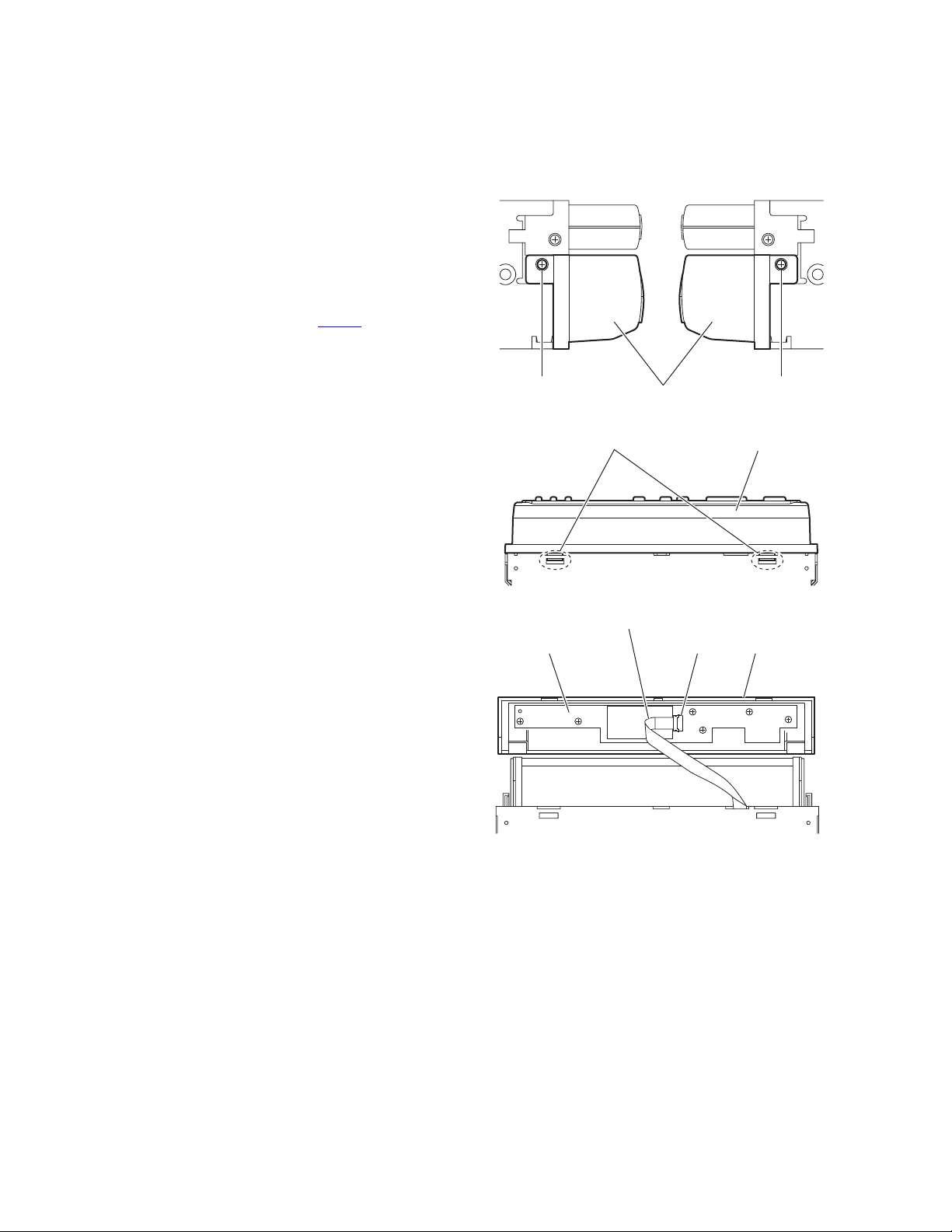
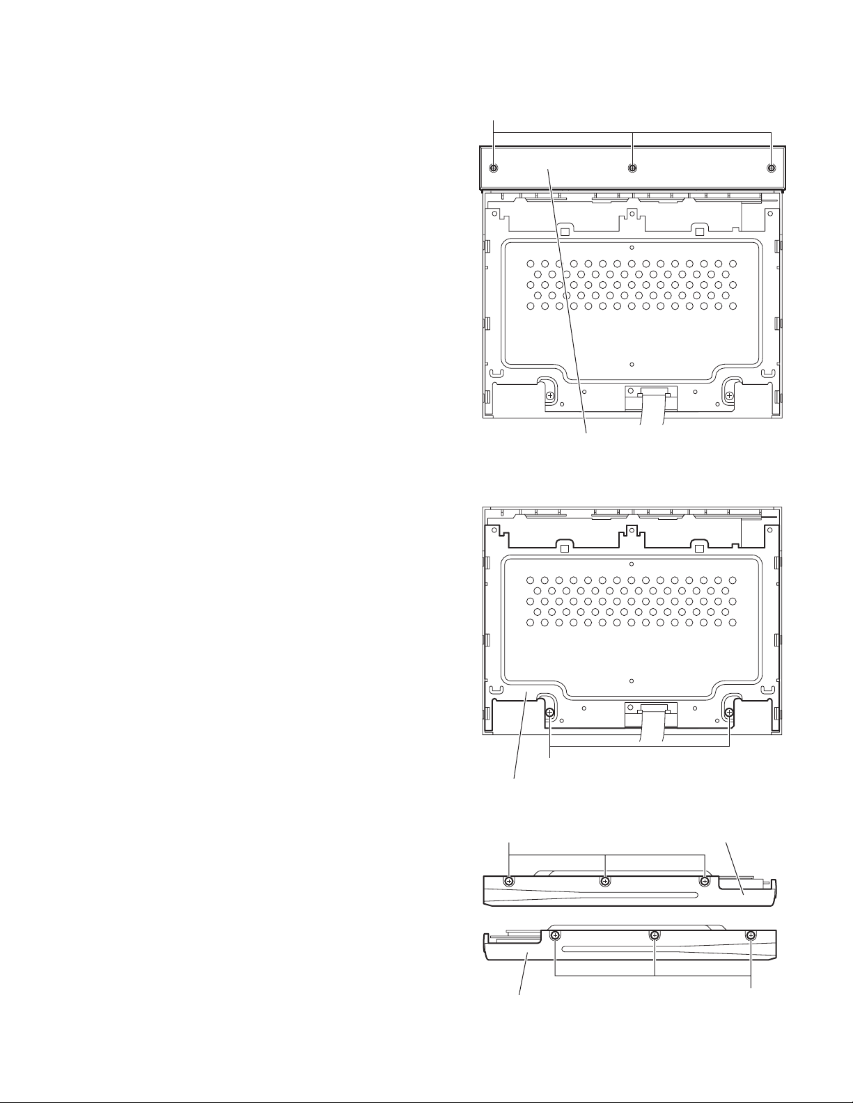
3.1.1 Removing the front assembly
(See Figs.1 to 3)
(1) From the both sides of the main body, remove the two
screws A attaching the front assembly to the main body.
(See Fig.1.)
(2) From the bottom side of the main body, release the two
claws a attaching the front assembly to the main body.
(See Fig.2.)
(3) Take out the front assembly forward from the main body.
(4) Lift up the lock lever of the connector CN471
key board and disconnect the card wire from it. (See Fig.3.)
on the front
A A
Front assembly
Fig.1
Fig.2
Card wire
Fig.3
CN471
Front assemblyClaws a
Front assemblyFront key board
1-4 (No.MA209)
Page 5
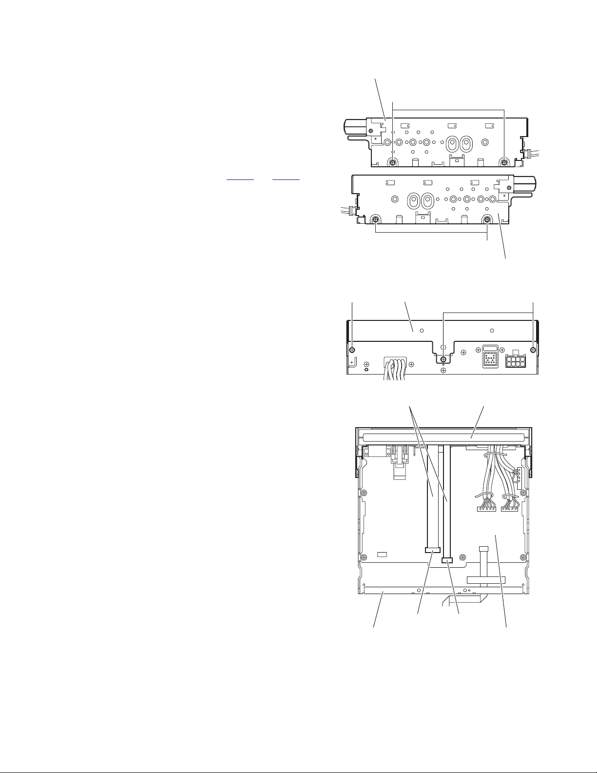
3.1.2 Removing the top drive unit
(See Figs.4 to 6)
• Prior to performing the following procedure, remove the front
assembly.
(1) From the both sides of the main body, remove the four
screws B attaching the top drive unit to the main body. (See
Fig.4.)
(2) From the back side of the main body, remove the three
screws C attaching the top drive unit to the main body. (See
Fig.5.)
(3) From the top side of the main body, lift the top drive unit
from the bottom case assembly.
(4) Lift up the lock lever of the connectors (CN391
on the system control board and disconnect the flexible
wires from it. (See Fig.6.)
(5) Take out the top drive unit from the bottom case assembly.
and CN392)
Top drive unit
B
B
Top case assembly
Fig.4
Top drive unit
Flexible wires
CC
Fig.5
Top drive unit
Fig.6
CN391CN392
System control boardBottom case assembly
(No.MA209)1-5
Page 6
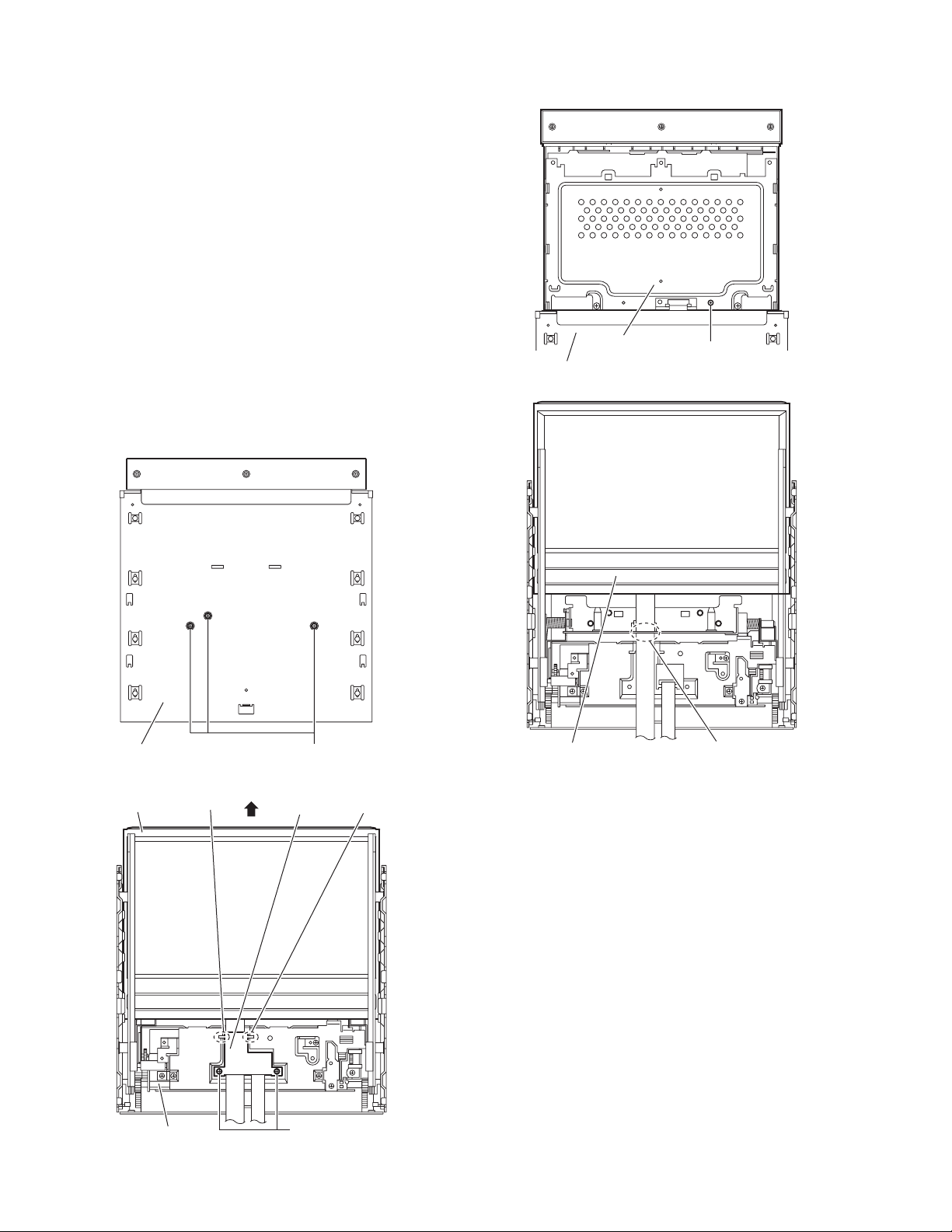
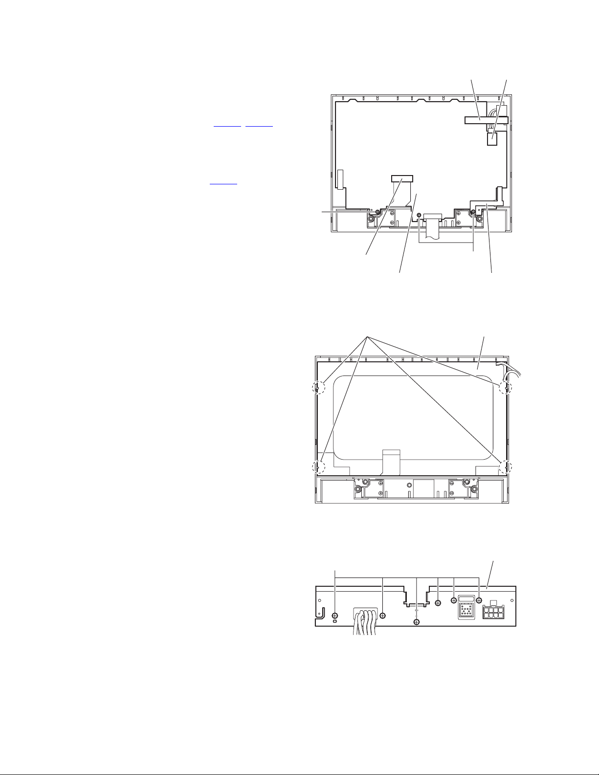
3.1.3 Removing the LCD assembly
(See Figs.7 to 10)
• Prior to performing the following procedures, remove the front
assembly and top drive unit.
(1) From the top side of the top drive unit, remove the three
screws D attaching the LCD assembly to the top drive unit.
(See Fig.7.)
(2) From the bottom side of the top drive unit, remove the two
screws E attaching the FPC guide and take out it. (See
Fig.8.)
(3) Move the LCD assembly in the direction of the arrow by
turning the feed gear. (See Fig.8.)
(4) From the top side of the top drive unit, remove the screw D
attaching the LCD assembly to the top drive unit. (See
Fig.9.)
(5) Take out the LCD assembly from the top drive unit.
Reference:
• When reattaching the LCD assembly, pass the flexible wire
through the slot c of the mecha assembly as before. (See
Fig.10.)
• When reattaching the FPC guide, pass it through the section
b as before. (See Fig.8.)
LCD assembly
D
Bottom case assembly
Fig.9
Bottom case assembly
LCD assembly Section b
Feed gear
1-6 (No.MA209)
Fig.7
Fig.8
D
FPC guide
E
Section b
LCD assembly
Slot c
Fig.10
Page 7
3.1.4 Removing the display rear cover
(See Fig.11)
• Prior to performing the following procedures, remove the front
assembly, top drive unit and LCD assembly.
(1) From the back side of the LCD assembly, remove the three
screws F attaching the display rear cover to the LCD assembly.
(2) Take out the display rear cover from the LCD assembly.
3.1.5 Removing the display back panel
(See Figs.12 and 13)
• Prior to performing the following procedures, remove the front
assembly, top drive unit, LCD assembly and display rear cover.
(1) From the back side of the LCD assembly, remove the two
screws G attaching the display back panel to the LCD assembly. (See Fig.12.)
(2) From the both sides of the LCD assembly, remove the six
screws H attaching the display back panel to the LCD assembly. (See Fig.13.)
(3) Take out the display back panel from the LCD assembly.
F
Display rear cover
Fig.11
G
Display back panel
H
Display back panel
Fig.12
Display back panel
H
Fig.13
(No.MA209)1-7
Page 8
3.1.6 Removing the monitor board
(See Fig.14)
• Prior to performing the following procedures, remove the front
assembly, top drive unit, LCD assembly, display rear cover
and display back panel.
(1) From the back side of the LCD assembly, remove the three
screws J attaching the monitor board to the LCD assembly.
(2) Disconnect the wires from the connectors (CN791
on the monitor board.
(3) Take out the monitor board with the insulator.
Reference:
• When attaching the screw J, attach it with the ground spring.
• After connecting the wire to the connector CN851
the new tape.
, CN851)
, fix it with
Ta pe
CN851
J
3.1.7 Removing the LCD module
(See Fig.15)
• Prior to performing the following procedures, remove the front
assembly, top drive unit, LCD assembly, display rear cover,
display back panel and monitor board.
(1) From the back side of the LCD assembly, release the four
section d attaching the LCD module while lifting up the LCD
module.
(2) Take out the LCD module from the LCD assembly.
Reference:
When releasing the LCD module, take care not to break it.
3.1.8 Removing the rear bracket
(See Fig.16)
• Prior to performing the following procedures, remove the front
assembly and top drive unit.
(1) From the back side of the bottom case assembly, remove
the six screws K attaching the rear bracket to the bottom
case assembly.
(2) Take out the rear bracket from the bottom case assembly.
K
CN791
Monitor board
Fig.14
Fig.15
J
Ground spring
LCD moduleSection d
Rear bracket
1-8 (No.MA209)
Fig.16
Page 9

3.1.9 Removing the system control board
(See Fig.17)
• Prior to performing the following procedures, remove the front
assembly, top drive unit and rear bracket.
(1) From the top side of the bottom case assembly, remove the
five screws M attaching the system control board to the bottom case assembly.
(2) Disconnect the wire from the connector CN351
tem control board.
(3) Take out the system control board from the bottom case
assembly.
3.1.10 Removing the front key board
(See Fig.18)
• Prior to performing the following procedure, remove the front
assembly.
(1) From the back side of the front assembly, remove the spac-
er from the front key board.
(2) Remove the eight screws N attaching the front key board
to the front assembly.
(3) Take out the front key board from the front assembly.
Reference:
After reattaching the front key board, cover it with the new
spacer.
on the sys-
M System control boardCN351 MM
Fig.17
N
Front key board Spacer
Fig.18
(No.MA209)1-9
Page 10
4.1 Service mode
4.1.1 Standard conditions
Power supply voltage:DC14.4V (11V to 16V)
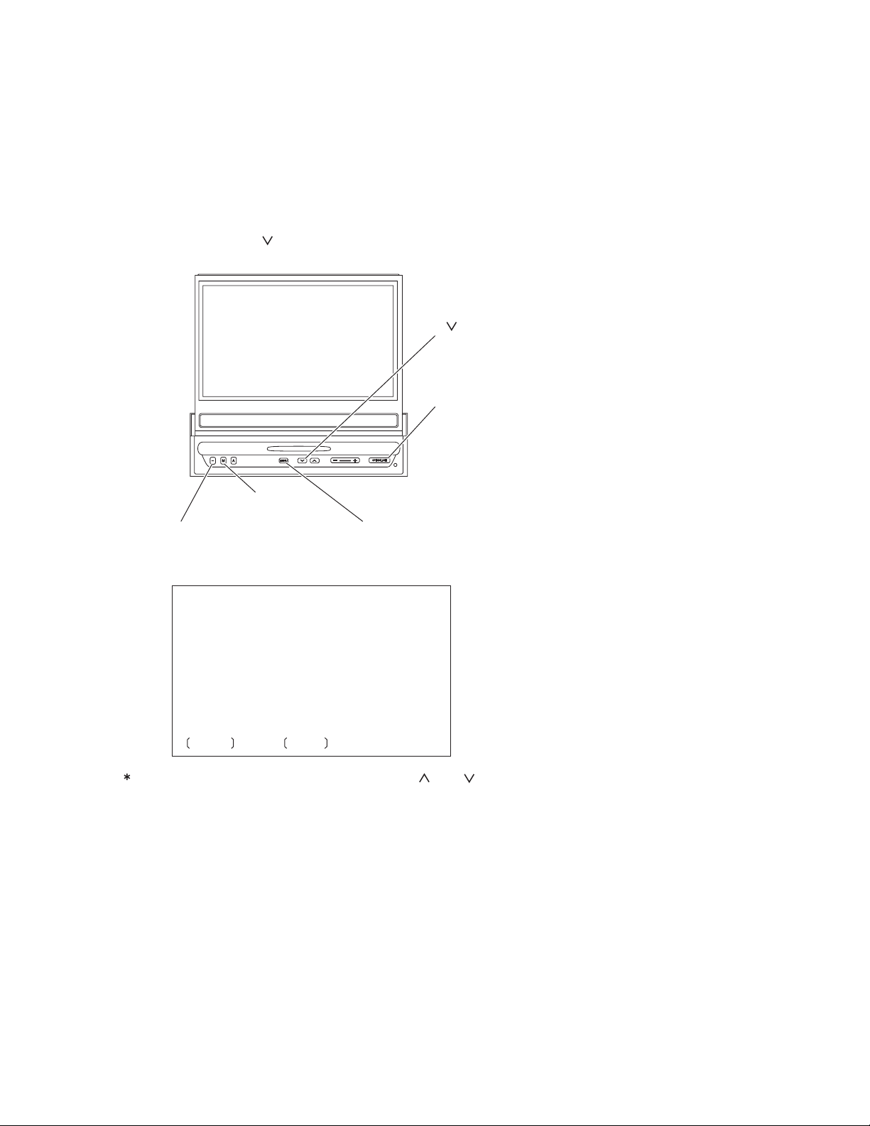
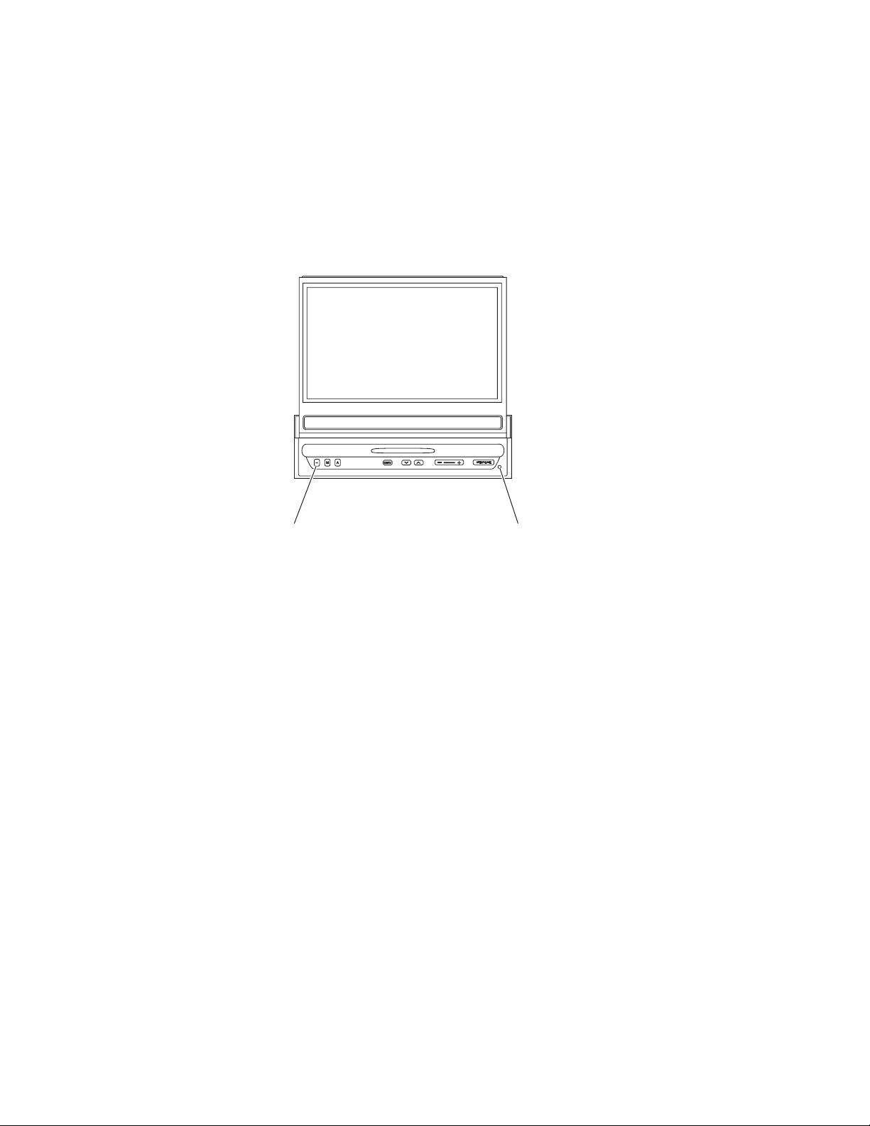
4.1.2 Service mode setting procedure
1. Press the [POWER] button, and the display panel will come out and stand upright.
2. Press the [POWER], [ ] and [OPEN/CLOSE] buttons in this order, and keep them
pressed for 3 seconds or more.
SECTION 4
ADJUSTMENT
[ ] button
[OPEN/CLOSE] button
[MODE] button
[POWER] button [MENU] button
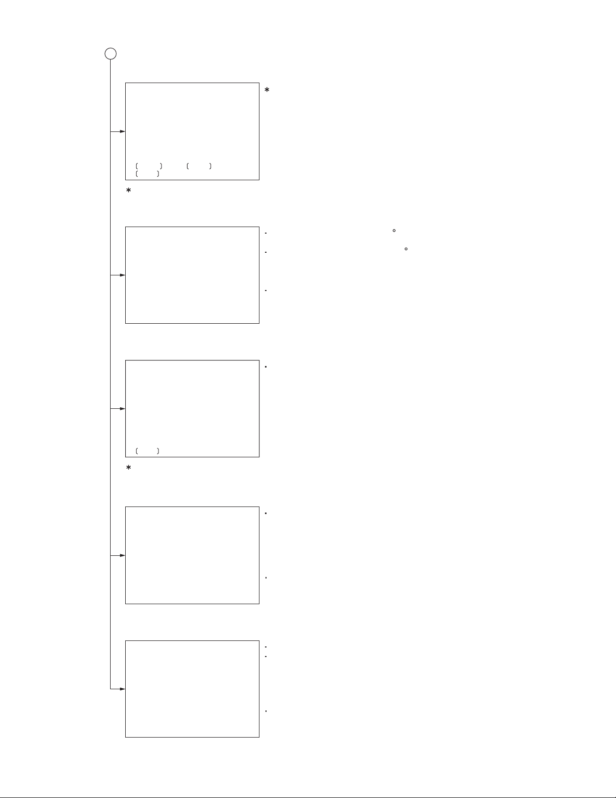
3. The service mode menu is displayed in the monitor.
Service Mode Menu
>
INITIALIZE ALL
INFORMATION
LCD SETTING MODE
MONITOR MECHA RUNNING
MONITOR MECHA CHECK
READ MECHA ERROR
CLEAR MECHA ERROR
INITIALIZE
DW/UP : SEL MODE : ENT
The service mode menu is selected with the [ ] or [ ] button on the main unit,
and the service mode menu is entered with the [MODE] button on the main unit.
4. To exit the service mode, press the [POWER] button on the main unit for more than 3 seconds.
1-10 (No.MA209)
Page 11
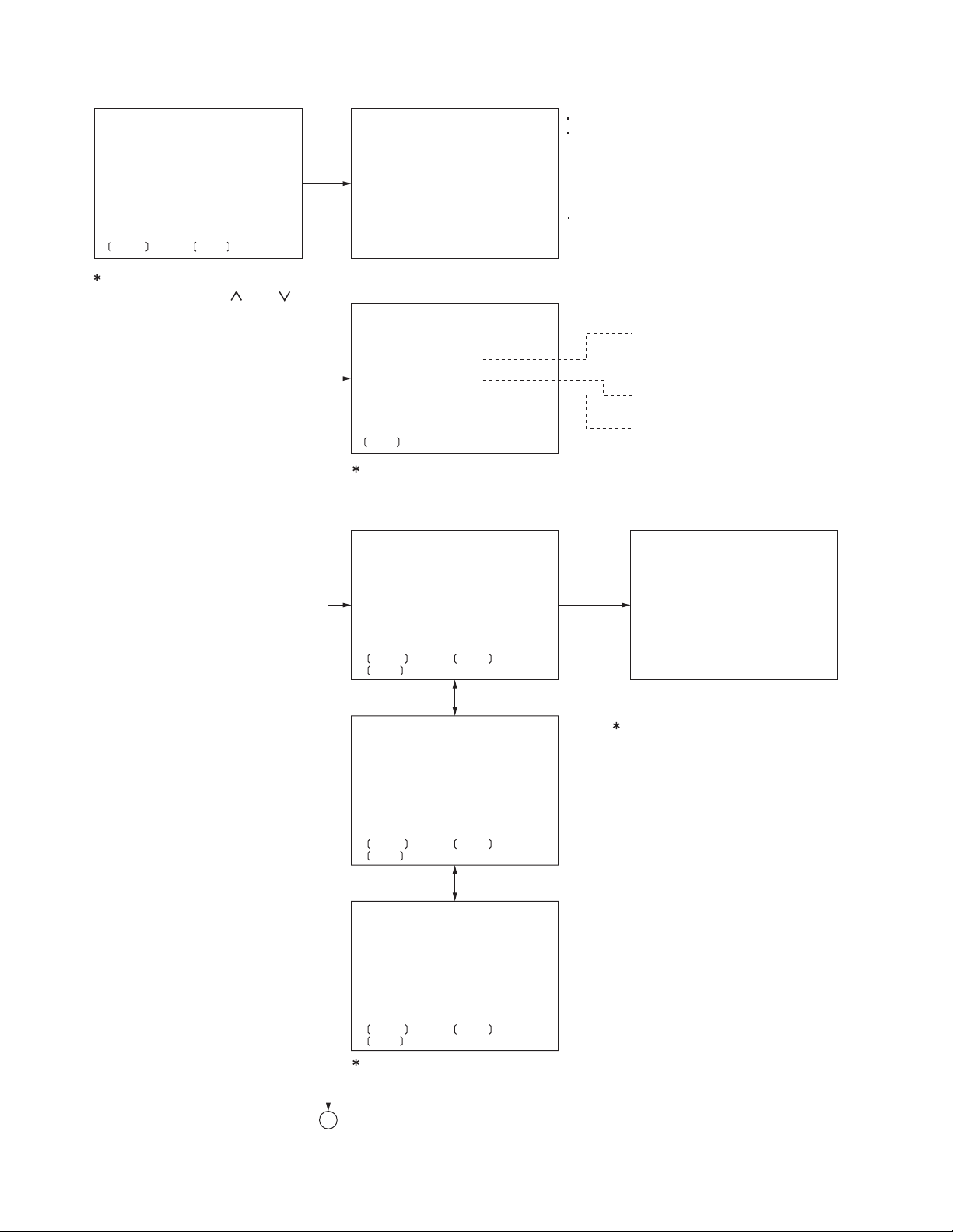
4.1.3 Operation procedures
Service Mode Menu
>
INITIALIZE ALL
INFORMATION
LCD SETTING MODE
MONITOR MECHA RUNNING
MONITOR MECHA CHECK
READ MECHA ERROR
CLEAR MECHA ERROR
INITIALIZE
DW/UP : SEL MODE : ENT
INITIALIZE ALL : All data are initialized to the factory default.
INITIALIZE ALL
"NOW EXECUTING" is displayed while the data is cleared.
After the data clear is completed, the screen returns to
NOW EXECUTING
COMPLETED
normal indication after "COMPLETED" is displayed for 3
seconds.
Data to be Initialized
All EEPROM data except the factory default of the system
micom and ROM collection data.
The service mode menu is
selected with the [ ] or [ ]
button on the main unit,
and the service mode menu
is entered with the [MODE]
button on the main unit.
INFORMATION : Area / Region indication / Version indication
INFORMATION
KV-M705
SYS VER XXXX XX
LCD INFO XX
TV TUNER VER XXXX
DOM
Version number of system micom and
ROM collection
This is used for technical support only.
Version number of TV tuner
(TV TUNER is connected.)
Area suffix of TV tuner
MENU : BACK
(TV TUNER is connected.)
Press the [MENU] button and the screen returns to the service mode menu.
LCD adjustment mode
LCD SETTING NTSC
COM AMPLITUDE
>
COM DC
DAC OUT
RGB AMPLITUDE
BRIGHT
GAMMA1
GAMMA2
SUB-BRIGHT R
SUB-BRIGHT B
DW/UP : SEL MODE : ENT
MENU : EEPROM WRITE
Indication
reshuffling
LCD SETTING NTSC
PHASE
>
CONTRAST
TINT
COLOR
PICTURE
INPUT MODE/SW
AGC SW ON
GAMMA TEST OFF
NTSC/PAL CHANGE
DW/UP : SEL MODE : ENT
MENU : EEPROM WRITE
Press the
[MENU]
button.
LCD SETTING NTSC
EEPROM WRITE
NOW EXECUTING
COMPLETED
Each setting value is written in EEPROM
by pressing the [MENU] button.
"NOW EXECUTING" is displayed while the data
is written.
After the data writing is completed, the screen
returns to service mode menu after
"COMPLETED" is displayed.
Indication
reshuffling
LCD SETTING NTSC
SETTING DISP ON>
DW/UP : SEL MODE : ENT
MENU : EEPROM WRITE
See "LCD adjustment" for details.
A
(No.MA209)1-11
Page 12
A
Monitor Mecha Running mode
MONITOR MECHA RUNNING
>
RUNNING MODE-1
RUNNING MODE-2
RUNNING MODE-3
RUNNING MODE-4
RUNNING MODE-5
RUNNING MODE-6
DW/UP : SEL MODE : ENT
MENU : BACK
This mode is not used for service.
To exit running mode, press the [POWER] button for
more than 3 seconds.
Then service mode is finished.
Press the [MENU] button and the screen returns to service mode menu.
Monitor Mecha Check mode
MONITOR MECHA CHECK
ANGLE SENSOR MIN : XXXX
ANGLE SENSOR MAX : XXXX
INITIALIZE OK
MIN : Value of the monitor angle 0 C entered by the
initialization processing.
MAX : Value of the monitor angle 105 C entered by the
initialization processing.
(The displayed value is the AD value, which is taken into
the system micom.)
"INITIALIZE OK/NG" indicates completion/incompletion
end of the initialization processing.
("NG" is displayed when mechanism initialization have
not been completed.)
Read Mecha Error history
READ MECHA ERROR
TOTAL ERROR : XXXXXX
E-1 : XXXXXX E01 : XXXXXX
E-2 : XXXXXX E02 : XXXXXX
E-3 : XXXXXX E03 : XXXXXX
E-4 : XXXXXX
E-5 : XXXXXX
MENU : BACK
Total number of errors, the first five and the latest three
errors are displayed.
Press the [MENU] button and the screen returns to service mode menu.
Clear Mecha Error history
CLEAR MECHA ERROR
NOW EXECUTING
COMPLETED
The Monitor Mecha Error history is cleared.
Data to be cleared
Monitor Mecha Error history stored in EEPROM.
Initialization of user setting data
INITIALIZE
"NOW EXECUTING" is displayed while the data is cleared.
After the data clear is completed, the screen returns to
NOW EXECUTING
COMPLETED
normal indication after "COMPLETED" is displayed
for 3 seconds.
Data to be Initialized
User setting data of the system micom
(All EEPROM data except the factory default of system
micom, ROM collection data and the Monitor Mecha
Error history.)
1-12 (No.MA209)
Page 13
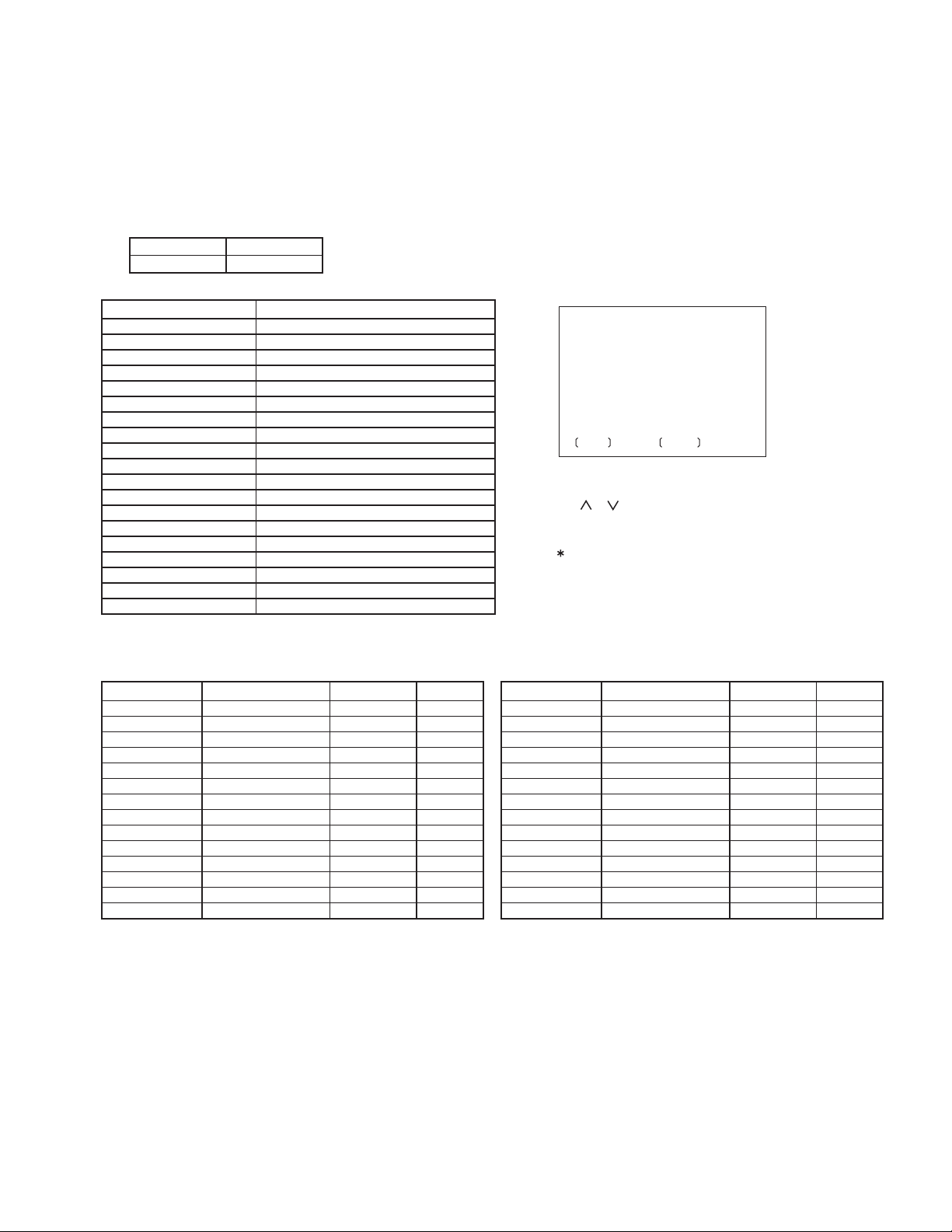
4.1.4 LCD adjustment
LCD free run frequency adjustment
(1) Set the main unit in a service mode.
(2) Select "LCD SETTING" of the service mode.
(3) Connect the frequency counter to TP708 and TP761 (GND) on the monitor board.
(Not supplying a signal in the input.)
(4) Select "DAC OUT" of LCD SETTING menu to adjust.
(5) Carry out this adjustment with both modes of NTSC and PAL.
(Change "NTSC/PAL CHANGE" of LCD SETTING menu)
NTSC
15.734kHz
LCD SETTING MENU
Item Contents
COM AMPLITUDE
COM DC
DAC OUT
RGB AMPLITUDE
BRIGHT
GAMMA1
GAMMA2
SUB-BRIGHT R
SUB-BRIGHT B
PHASE
CONTRAST
TINT
COLOR
PICTURE
INPUT MODE/SW
AGC SW ON
GAMMA TEST OFF
NTSC/PAL CHANGE
SETTING DISP ON
PAL
15.625kHz
Amplitude of the common voltage
Center value of the LCD pulse
Free run frequency of the LCD
Amplitude of black-black
Brightness
GAMMA point 1
Difference with GAMMA point 1
Red brightness
Blue brightness
Phase of R-Y/B-Y
Contrast of video input
Hue
Deepness of a color
Picture
This mode not using it by service.
This mode not using it by service.
This mode not using it by service.
Reshuffling of NTSC/PAL
On/off for indication of adjustment value
LCD SETTING NTSC
COM AMPLITUDE XXH
MODE : BACK DW/UP : SET
Main unit operation in adjustment
[MODE] key : Return to LCD SETTING menu.
[ ], [ ] key : Change value, one step changes by one
time of input
Carry out this operation with both modes of NTSC and PAL.
When all the adjustment values are input, press the
[MENU] button to memorize the values in EEPROM.
When the power supply is turned off without pressing
the [MENU] button, the adjustment values are not
memorized.
Adjustment for all version (Carry out this adjustment with both modes of NTSC and PAL.)
NTSC adjustment
Item Production jig Def value
COM AMPLITUDE
COM DC
DAC OUT
RGB AMPLITUDE
BRIGHT
GAMMA1
GAMMA2
SUB-BRIGHT R
SUB-BRIGHT B
PHASE
CONTRAST
TINT
COLOR
PICTURE
Adjustment of frequency
3E
0A
DD
30
85
FF
80
85
30
A0
98
7B
10
Reference value
6D
28
CE
30
85
FF
84
8A
30
AB
98
7D
10
Adjustment
Adjustment
Adjustment
Adjustment
Fixed value
Fixed value
Fixed value
Adjustment
Adjustment
Adjustment
Adjustment
Adjustment
Adjustment
Fixed value
PAL adjustment
Item Production jig Def value
COM AMPLITUDE
COM DC
DAC OUT
RGB AMPLITUDE
BRIGHT
GAMMA1
GAMMA2
SUB-BRIGHT R
SUB-BRIGHT B
PHASE
CONTRAST
TINT
COLOR
PICTURE
Adjustment of frequency
3F
1A
D0
30
85
FF
80
85
30
A0
92
7F
10
Reference value
72
25
D0
30
85
FF
84
8A
30
AB
91
84
10
Adjustment
Adjustment
Adjustment
Adjustment
Fixed value
Fixed value
Fixed value
Adjustment
Adjustment
Adjustment
Adjustment
Adjustment
Adjustment
Fixed value
(No.MA209)1-13
Page 14
SECTION 5
TROUBLESHOOTING
5.1 Mechanism initialization
Operate the mechanism initialization when replacing the top drive unit.
5.1.1 Operation procedure of mechanism initialization
(1) Setup the service mode, and operate "INITIALIZE ALL".
(Refer to "4.1.2 Service mode setting procedure" and "4.1.3 Operation procedures")
(2) After the all data are initialized, press the [RESET] button of the main unit.
(3) After the display panel is closed, start the operating the mechanism initialization.
(4) After the operating mechanism initialization, press the [POWER] button of the main unit for more than 3 seconds.
[POWER] button [RESET] button
1-14 (No.MA209)
Page 15
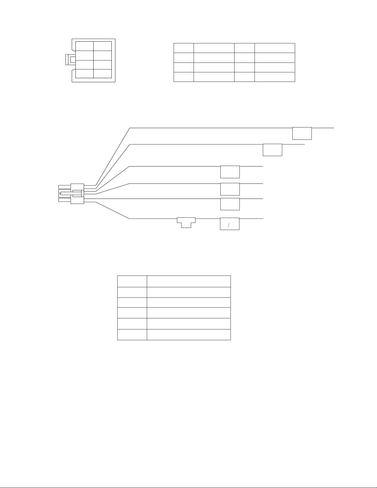
5.2 8 PIN CORD DIAGRAM
OR/WH
RD
VI/WH
L.GN
NC
NC
YL
BK
BK
RD
OR
L.GN
VI/WH REVERSE
Black
Red
Orange
Light Green
WH
YL
VI
White
Yellow
Violet
ACC
MEMORY
GND
ILL
PARKING
L.GN PARKING
OR/WH ILL
RD ACC
BK GND
YL MEMORY
ACC Line
Memory Backup Battery+
Ground
Illuminations Control
Parking Brake
3 A
ILLUMI
POWER
LEAD
GROUND
POWER MEMORY
LEAD BACKUP
REVERSE
PARKING
REVERSE
Reverse Gear Signal Lead
(No.MA209)1-15
Page 16

Victor Company of Japan, Limited
AV & MULTIMEDIA COMPANY CAR ELECTRONICS CATEGORY 10-1,1chome,Ohwatari-machi,Maebashi-city,371-8543,Japan
(No.MA209)
Printed in Japan
VPT
Page 17

SCHEMATIC DIAGRAMS
IN-DASH 7-INCH WIDESCREEN MONITOR
KV-M705, KV-M706
CD-ROM No.SML200510
KV-M705
Area suffix
E ------------- Southern Europe
UT ------------------------- Taiwan
UN --------------------- Indonesia
HUN ------------------ Indonesia
U -------------------- Other Areas
KV-M706
Area suffix
J ------------- Northern America
E ------------- Southern Europe
UT ------------------------- Taiwan
UN --------------------- Indonesia
U -------------------- Other Areas
Lead free solder used in the board (material : Sn-Ag-Cu, melting point : 219 Centigrade)
Contents
Block diagram
Standard schematic diagrams
Printed circuit boards
COPYRIGHT 2005 Victor Company of Japan, Limited.
2-1
2-3
2-11 to 14
No.MA209SCH
2005/10
Page 18

Safety precaution
!
Burrs formed during molding may be left over on some parts of the chassis. Therefore,
pay attention to such burrs in the case of preforming repair of this system.
Page 19

< MEMO >
Page 20

e
C
O
N
C
C
N
E
E
E
S
V
C
Y
G
Block diagram
TFT
LCD
MODULE
Monitor section
CN791 CN851
CONTROL
STH1, STH2
STV1, STV2
CLK1 to CLK3
OEV1 to OEV3
CPV, OEH
IC701
TFT
HSYNCIN
VDBIN
BLACK, POL
PD
POSSET
HPOS1
VPOS1
RESET
ROUT, GOUT, BOUT
VCOM
Q651 to Q654
VCOM
IC741
SYNC BUFF.
IC761
PLL
Q701, Q702
POSITION SET
IC702
RESET
COM_OUT
SYNC_OUT
DAC_OUT
NTSC/PAL_OUT
HSY_IN
R_IN2
G_IN2
B_IN2
SW1, SW2
IC601
VIDEO
PROCESSOR
CLK_LCD
TX_LCD
Mecha
VIDEO_IN
IC691
VIDEO IN
BUFFER
C_VIDEO(+)_IN
Main s
BACK
LIGHT
T851
TRANS.
IC811
B/L DRIVER
LTBOX, CPHSEL, QHSEL
HOUT
VOUT
IC703
INVERTER
12V
ENA
HSYNC
VSYNC
5V
IC911
17V 12V
REG.
CS
IC521
PORT
EXPANDER
CS
IC631
OSD
CONTROLLER
IC801
14V 5V
REG.
IC901
SW
REG.
EXP_DAT
EXP_CLK
EXP_STRB
EEP_DAT
EEP_CLK
IC511
LEVEL
TOLERANCE
TX_LCD
CLK_LCD
INV_PWR
SYS5V
CN501
CN392
I
S
RE
P
CON
2-1
Page 21

echa section
S3201
CLOSE SW
CLSW ANGSW
P3201
ANGLE SW
S3601
SLIDE PULSE
S361
HSW
CN332
HSW, PULSE
VR351
ANGLE SENSOR
CN331
ANGSENS
ain section
VOUT+
CCLK
CDATA
NTSC/PAL
EPSDATA, EPSCL
EXPDAT, EXPCLK
EXPSTRB
VIDEO5V
IC303
8V 5V
REG.
SW5V, A9V, 8V
IC301
SYSTEM
REGULATOR
ACC
CN301
POWER
CONNECTOR
SW+B, PWR
MVCNT
CNTL0, CNTL1, CNTL2
CN301
CN391
PULSE, HSW, ANGSW, CLSW
ANG_SENS, MO_PWR, MVCNTL
MO_CTL0, MO_CTL1, MO_CTL2
IC101
SYSTEM
CTL
ACCCHK
REVERSE
PARKING
FPKEY0
FPKEY1
FP_REM
OPEN/CLOSE
LED_CONT
RESET
IC102
RESET
IC301
REGULATOR
VMUTE
MONIMUTE
JBUSIO, JBUSSCK
JBUSSI, JBUSSO
IC103
JBUS BUFF.
RST
ASEL0
ASEL1
CN351
IC253
AUDIO
SELECT
IC202, IC203
Front section
REMOCON
CN471
S431 to S434
S441 to S444
IC312
MOTOR
VR
VOLTAGE
IC251
AUDIO
ISOLATION
IC252
AUDIO
ISOLATION
AMUTE
VSEL0
VSEL1
VIDEO
AMP
IC461
REMOCON LED_CONT
FPKEY0
FPKEY1
SWITCH
VIDEO SELECT
TV_L, TV_R
Q411, Q412
DIMMER
S435
OPEN/CLOSE
SWITCH
IC331
MOTOR
DRIVER
INP1L, INP1R, INP1_V
OUT_L, OUT_R
INP2_L, INP2_R, INP2_V
Q256 to Q258
AUDIO MUTE
IC201
ISO &
TV_V
OPEN/CLOSE
OUT_V
SI/SO, SCK
D401 to D421
CN312CN311
INPUT1
INPUT2
CN372CN371CN373
OUTPUT
CN361
AV_BUS
PAN EL
LIGHT
RESET
S451
RESET
SWITCH
2-2
Page 22

1
R
Standard schematic diagrams
Main section
LVA10619-1
TP353
TP351
TP352
TP354
TP355
TP303
PARKING
TP307
TP356
FP_REM
DGND
RST
FPKEY0
FPKEY1
OPEN/CLOSE
LED_CONT
R347
Q342
R345
Q341
47k
R342
R341
TP357
TP358
TP359
TP360
TP305
TP304
NI
C302
0.1/50
C303
NI
C301
47k
MA8062/M/-X
REVERSE
L301
QQR1620-001
NIC305
0.1/50
C304
L302
22
NQL79GM-220X
R311
NI
NI
C308
0.1/50
C309
UN2211-X
D341
C341
0.01
REMOTE_IN
REVE
R302
D302
10k
MA111-X
C310
47/16
100k
R301
0.01C307
3300/16C306
D301
1N5401-F64
PGND
47k
NI
REM_IN
4.7k
R348
5.1k
R346
10k
C343
10/16
PARKING
PARK
R303
47k
TP308
82k
R304
D303
TP309
MA8062/M/-X
100k
R306
33k
R305
R343
NI
D342
C342
NI
NI
Q301
2SD601A/QR/-X
REMOCON
TO_FP
OPEN/CLOSE
TO CN471
(SHEET 2)
LED_CONT
REVERSE
REMOTE_IN
POWER_CON
GND
5V
GND
RESET
FPKEY0
FPKEY1
ILL_B
ILL_GND
ILL10V
ILL_GND
CN301
QGA4201F1-08
ILLMI
ACC
PARKING
NC
GND
MEMORY
CN351
QGF0534F1-13X
13
R351 0
12
11
10
R352 0
9
R353 0
8
R354 0
7
R356 0
6
5
4
3
R355 0
2
1
1
2
3
4
5
6
7
8
C337
0.1/50
TP301
TP302
REVERSE
D317
MA111-X
TP306
Q343
UN2211-X
Q302
2SD601A/QR/-X
Q303
UN2213-X
TP310
Q304
2SB709A/QR/-X
R357
NI
R358
0
Q311
2SB709A/QR/-X
R324
22k
47k
C334
0.1
R325
2.2k
R326
Q312
UN2211-X
ILL
18k
R307
BAT_DET
82k
R308
R309
10k
ACCCHK
8.2kR310
R312
C311
0.01
C312
10/16
SYSTEM_REG
IC301
R2S25400DS-E
EXT
ANT
ACC
VDD
SW5V
ACC5V
ANTC
0V
5.0V
5.8V0V5.1V
D304
MA111-X
0.01C317
5.4V
14.2V
R328
10k
TP315
TP314
TP313
C319
0.1/16
10/16
C318
0.01
C320
R327
47k
13.6V
TP311
TP312
4.7k
0.1/16C314
100/10C316
47/16
0.01C315
C313
8V
CTRL
ILMI
VCC
0.4V
TP316
AJ
BAT
9V
9.1V
4.9V
8.1V
1.3V
8.8V
TP317
A9V
R313
5.6k
TP318
1k
R314
10/16
C323
C322
47/16
0.01
C324
0.01
C321
PWCONT
TP319
GND
151413121110987654321
0V
NI
R315
Q305
NI
Q306
NI
C325
47/16
INP2
OUT
INP1
QNZ0690-001
TV_V_GND
MEMORY
AV_BUS
REMOTE
TV_S_GND
QGA2501C1-05
INP2_VGND
INO2_AGND
QGA2501C1-07
OUTVGND
OUTAGND
OUTAGND
QGA2501C1-06
INP1VGND
INP1GND
INP1GND
INP2_R
CN372
VMUTE
VSEL1
VSEL0
C203
R231
10/16
100
C227
R232
150
R208
150
R207
10/16
100
C225
R226
10/16
100
C201
R225
10/16
6.8k
R202
180
R201
100
C226
R228
10/16
100
C202
INP1_VGND
INP2_VGND
C251
4.7/25
C252
4.7/25
C253
4.7/25
C254
4.7/25
C255
4.7/25
C256
4.7/25
INP1_V
150
R203
0R241
1kR242
1kR243
0R244
0R245
1kR246
R227
150
R204
100
IC251
NJM4565V-X
0V
4.5V
4321
VCC-
AUDIO_ISO1
2IN+
5678
4.5V
4.5V
0V
4.5V
4321
VCC-
AUDIO_ISO2
2IN+
5678
4.5V
4.5V
IC252
NJM4565V-X
10/16
C257
100p
R263
15k
4.5V
4.5V
1OUT1OUT
1IN-
1IN+
VCC+
2OUT
2IN-
4.5V
9.1V
R264
15k
C259
100p
C258
100p
R265
15k
4.5V
4.5V
1IN-
1IN+
VCC+
2OUT
2IN-
4.5V
9.1V
R266
15k
C260
100p
TP361
TP362
TP363
TP364
TP365
CN361
GND
1
C361
NC
2
NI
3
L361
TV_V
4
0
SCK
5
NC
6
D361
RB160M-30-X
7
8
9
R361
TV_L
10
100
SI/SO
11
TV_R
12
R362 NI
100p
C362
CN371
INP2_V
1
2
3
INP2_L
4
5
OUTV
1
2
OUTL
3
4
OUTR
5
6
NC
7
CN373
INP1_V
1
2
INP1L
3
4
INP1R
5
6
C384
TP366
SCK
AGND2
TV_L
SI/SO
TV_R
D364
NI
3
2
-
1
NI
NI
100p
C363
D362
C371
0.001
C372
0.001
C373
0.001
C374
0.001
PGND
TP370
TP371
100p
100p
C375
100p
C376
TP367
TP368
D363
TP372
TP373
100p
C377
TP369
TP380
TP379
TP381
TP382
TP374
TP375
TP376
TP377
TP378
C381
NI
INP2_V
INP2_VGND
C382
NI
OUT_V
VGND
R297
OUT_L
100
AGND1
R298
OUT_R
100
C383
NI
INP1_V
INP1_VGND
C380
100p
0.001
C378
0.001
C379
PGND
C331
0.01
C332
0.01
C333
0.01 NI
NI
NI
INP2_V
R255
15k
R256
100k
22k
R251
R257
15k
22k
R252
R258
15k
R259
15k
R260
100k
22k
R253
R261
15k
22k
R254
R262
15k
C231
0.1
C232
0.1
C206
0.01
47/16C261
1.7V
1.7V
1.7V
1.7V
1.7V
1.7V
1.7V
8.0V
47k
R267
47k
R268
47k
R269
0.1/16C266 0.1/16C262
47k
R270
ISO&VSEL
IC201
NJM2526V-X
VIN4 GND
VGND4
VOUT2
VIN3
MUTE
VGND3
SW2
VGND1
VOUT1
VIN1
SW3
VGND2
SW1
V+
VIN2
87654321
R273
22/16
C265
C263
0.1/16
15k
100p
C264
R271
R274
R275
22/16
C269
C267
0.1/16
R276
15k
100p
C268
R272
0V
161514131211109
1.0V
0V
R233
10k
0V
1.0V
R206
470
0V
4.8V
1.7V
R205
470
R277
0
1k
1k
1k
1k
TP201
D202
MA111-X
R234
NI
C207
0.1
47k
R238
C208
10/25
D201
MA111-X
21250R278
47kR279
47kR280
4.5V
9.1V
16 15 14 13 12 11 10 9
2X
VDD
0.1/16C271
47/16C270
0Y2YY3Y1Y
4.6V
4.5V
MONIMUTE
100k
R209
100k
R237
R235
0
4.5V
1X
CD4052BM-X
4.5V0V4.5V
R217
1M
C217
0.1
R221
1M
C221
0.1
C272
4.7/25
1k
R281
AUDIO_SEL
C209
0.1/16
IC202
MM1228XF-X
1.9V
IN
0V
0V
SW2 IN3
4321
R219
VIDEO_AMP_MONI
47k
C210
0.1/16
IC203
MM1228XF-X
1.9V
IN
0V
SW1
1.9V
IN1
0V
SW2
4321
VIDEO_AMP_OUT
R220
47k
TV_L
TV_R
C273
4.7/25
1k
R282
0.1V0V4.5V
4.5V
0XX3X
IC253
INH
0V0V0V 0V
C204
NQR0288-004X
100/10
K201
C205
0.1/16
R215
0
C211
470/16
0V
GND
8765
8.0V
OUTSW1
1.8V
VCCIN1
0V0V
0V
GND
8765
1.8V
OUT
8.0V
VCC
1.9V
IN3
47kR283
47kR284
100pC275
100pC274
A
B
VEE
VSS
87654321
R210
150
R218
C218
0.1
C213
470/16
R222
1M
C222
0.1
AGND2
VOUT+
R211
1M
150
R214
0
R212
150
R213
150
VGND
OUT_V
R285
10k
R286
10k
Q252
UN2211-X
C276
4.7/25
R290
R291
C277
4.7/25
VIDEO+5V
IC303
BA00ASFP-X
CNTL
VIN
GND
VOUT
ADJ
12345
4.7V
C344NIC347
Q251
UN2211-X
R287
1k
C278
100p
47k
C279
100p
47k
R288
1k
8.1V0V5.0V
C345
0.1
R295
NI
2.2kR289
R332
1.2V
1k
MONI5V
R333
6.8k
R334
2.2k
0.01
C346
10/16
D251
MA111-X
Q254
UN2111-X
AMUTE
Q253
C280
47/16
Q258
2SB709A/QR/-X
UN2211-X
ASEL0
ASEL1
C281
NI
R293
2.2k
D252
MA152WA-X
3
R294
2.2k
1
2
C282
NI
2-3
Page 23

R315
Q308
2
A
2
R
1
R318 47k
Q307
UN2211-X
C329 10/25
2SD601A/QR/-X
R317
10k
R323
22k
R322
47k
RSQ035P03-W
L303
4.7
C335 10/25
R321
47k
C328
0.1
C327
0.1
Q310
UN2211-X
IC302
14.2V
D
DDG
123
14.2V
14.2V
14.2V7.1V
456
D
S
R320
47k
14.2V
C330
0.1
47k
R319
Q309
UN2211-X
NTSC/PAL
VMUTE
AMUTE
MONIMUTE
PULSE
MO_PWR
MO_CNTL0
MO_CNTL1
MO_CNTL2
ANGSW
HSW
CLSW
OPEN/CLOSE
MVCNTL
CN101
QGA1002F1-07X
1
TX
FLHCLK
2
CLK
FLHDI
3
DI
FLHDO
4
DO
5
RESET
NI
6
VDD
7
GND
R153
CCFL_DIM
TX
NI
47kR154
R155
ANG_SENS
DGND
R157 NI
RST
FPKEY0
FPKEY1
R158 NI
LED_CONT
FP_REM
R159 470
4.9V
R144 470
R145
0V
470
R167
4.9V
470
R172
0V
470
0V
TP131
4.5V
R156
470
4.9V
R146
4.9V
470
0V
470R147
0V
470R148
R149
0V
470
4.7V
5.1V
5.1V
0V
TP132
0V
TP133
0V
TP134
0V
TP135
4.9V
0V
0.2V
470R150
0V
TP137
R151
2.8V
470
0.3V
TP138
C124
5.0V
0.1
C125
100p
47k
R103
470k
R152
R160
0
10kR101
10k
R102
10k
R171
ASEL1
VSEL0
VSEL1
470R143
470
470
470
TP129
R142
R141
R168
0V0V4.9V0V4.9V0V4.8V0V4.9V
ASEL1
VSEL0
VSEL1
DIMMER
76
NTSC/PAL
77
VMUTE
78
AMUTE
79
MONIMUTE
80
81
PULSE
82
FPPWR
83
MOTPWR
84
MOTCNT0
85
MOTCNT1
86
MOTCNT2
87
ANGSW
88
HSW
89
CLSW
90
91
92
93
94
OPEN/CLOSE
95
DAVSS
96
MOTVR
97
98
CCFL_DIM
99
100
DAVDD
VREF-
FP_KEY0
1 2 3 4 5 6 7 8 9 10111213141516171819202122232425
0V0V0V
C103
C102
C129
0.001
0.001
0.001
R163
10k
R161
10k
R162
10k
MON_PWR
PWCONT
C326
0.1
TP319
NI
Q305
NI
Q306
NI
C325
47/16
R316
NI
R335
0
NMFZ018-3R0X-E
F301
332
k
MONI5V
51
111-X
ILL
ACCCHK
PWCONT
MON_PWR
EPSCL
EPSDA
ASEL0
MONI5V
470R140
470
470R138
470R169
TP127
TP125
TP124
R137 470
ANGLE
4.4V0V5.0V
0.1
C104
4.9V
MONI5V
10k
R118
0V
5.3V0V5.0V
ACC
PWCONT
IC101
MN101C49KEF
VREF+
VDD
OSCO
5.0V
2.3V
0.1
0.1
C105
C106
3p
X101
C1073pC108
NAX0688-001X
OSCI
2.3V0V2.0V
470
R105
20MHz
5.1V
ILLUMI
VSSXIXO
22p
C127
R136 470
0V
EPSDA
2.4V0V5.0V
X102
32.768kHz
R139
ASEL0
MON_PWR
FP_KEY1
SENCK
5.0V0V5.0V
2.7V
470
R104
SENCK
TP123
TP122
TP121
TP120
0V0V0V0V0V0V0V
EPSCL
MMODTXRX
EXPCLK
0V
0V
4.9V
2.2kR176
2.2kR175
3.3kR107
22p
C128
NAX0244-001X
EXPCLK
TP119
FLHSDA
PARK
REVE
SI/SO
TP118
TP117
5.1V
0V
51525354555657585960616263646566676869707172737475
BACK
PARKING
JBUSSCK
CHROCLK
CHRODATA
EXPSTRB
EXPDATA
LED_CONT
BUZZER
FLHBSY
FLHCLK
0V0V0V
5.0V
330R108
TP141
FLHCLK
FLHDITXFLHDO
JBUSIO
JBUSSI
JBUSSO
JBUSINT
REM_IN
FP_REM
C109
100p
R123 100
R122 1k
0V
50
0V
49
0V
48
0V
47
0.1V
46
0.1V
R121
45
470
0V
44
0V
TP114
43
0V
42
470R120
0V
41
VPP
0V
TP113
40
0V
TP112
39
0V
38
3.3kR106
0V
37
0V
TP109
36
0V
R119
35
470
0V
TP108
34
5.0V
33
RESET
5.0V
R165
32
VDD2
0
0V
31
5.0V
30
5.0V
29
0V
28
0V
27
BATT
0V
26
TP105
100k
R117
TP101
0R109
NIR110
C110
100p
TP102
BZ101
QAN0023-001Z
TP142
Q101
UN2211-X
3.9k
3.9k
3.9k
3.9k
R114
R111
R113
R112
R126
100k
R125 100
R124 4.7k
R127
TP116
22k
TP115
CCLK
CDATA
EXPSTRB
EXPDATA
C118
0.1
C119
0.1
REM_IN
R177
10k
BAT_DET
R178
10k
330/6.3
C113
0.1
C112
C114
R115
47k
TP104
C111
BD4833FVE-W
NI
5.0V
123
OUT
0V
SUB
0V
NC
R130 10k
0V
5.0V
1OE
VDD
141312111098
0V
5.0V
4OE
1A
0V
0V
4A
1Y
R128
0V
0V
2OE
4Y
100
0V
0V
2A
3OE
5.0V
0V
2Y
3A
0V
0V
3Y
GND
7654321
NI
C120
NI
IC102
IC103
R129 47k
SN74AHCT126PW-X
L101
22
TP103
C116
0.1
220
R116
D101
MA111-X
5.0V
VCC
0V
45
GND
47/16
C117
Q102
C126
NI
UN2111-X
SCK
PGND
F391
R131
100k
R132
330
R133
100
C123
C121
0.047
NMFZ018-1R5X-E
TP321
TP322
TP323
TP324
MO_CNTL0
MO_CNTL1
MO_CNTL2
MVCNTL
MO_PWR
R134
NI
TP325
22k
ANG_SENS
CLSW
ANGSW
HSW
PULSE
R135
47k
TP327
TP328
TP331
TP333
TP332
NTSC/PAL
CDATA
CCLK
EXPSTRB
EXPDATA
EXPCLK
EPSDA
EPSCL
TP335
TP336
TP337
TP338
TP339
R396 NI
R395 NI
SENCK
CCFL_DIM
TP340
TP341
TO_MONITOR
CN391
C391
0.1
QGF0534F1-16X
1
SYS14
2
SYS14
3
GND
4
GND
5
CNTL0
6
CNTL1
7
CNTL2
8
MVCNT
9
PWR
C392 0.1
10
5V
11
TP329
TP330
TP334
R381 0
R382 0
R383 0
R384 0
R385 0
R386 0
R387 0
R388 0
R389 0
R390 0
R391 0
C393
0.1
C395
100/10
C394
0.1
L391
R3920
10
R3930
NQL49CM-100X
C396
10/25
C397
10/25
GND
12
ANGSENS
13
CLSW
14
ANGSW
15
HSW
16
PULSE
CN392
QGF0534F1-24X
1
NTSC/PAL
2
GND
3
VIDEO
4
GND
5
DATA
6
CLK
7
STROBE
8
DATA
9
CLK
10
DATA
11
CLK
12
VCC
13
GND
14
GND
15
+B
16
+B
17
SENCK
18
DIMMER
19
+B
20
+B
21
+B
22
GND
23
GND
24
GND
TO CN301
(SHEET 4)
TO CN501
(SHEET 3)
TP326
VGND
AMUTE
C280
47/16
Q258
UN2211-X
Q255
UN2111-X
R292
D253
10k
ASEL0
ASEL1
C281
NI
R293
2.2k
WA-X
3
R294
2.2k
2
C282
NI
C283
47/16
Q256
2SD1781K/QR/-X
Q257
2SD1781K/QR/-X
OUT_L
AGND1
OUT_R
MA8110/M/-X
1.VOLTAGES ARE DC-MEASURED WITH A DIGITAL VOLT METER.
CONDITION...DC SUPPLY 14.4V
2.UNLESS OTHERWISE SPECIFIED
ALL RESISTORS AER 1/10W 5% METAL GLAZE RESISTOR
ALL CAPACITORS ARE 50V OR 25V CERAMIC CAPACITOR
ALL RESISTANCE VALUES ARE IN OHM
ALL CAPACITANCE VALUES ARE IN uF(p=pF)
ALL E.CAPACITORS ARE SHOWN IN THE FORM OF CAPACITANCE(uF)/RATED VOLTAGE(V)
3.N.I STANDS FOR NOT MOUNTED PARTS.
SHEET 1
2-4
Page 24

1
2
3
Front section
LVA10619-2
OUT
GND
123
4.9V0V4.9V
470
VCC
C461
10/25
R461
47
REMOCOM
IC461
RPM6938-V4
R462
R463
10k
R419
0
Q411
NI
R411
NI
R421
270
D421
SML-310VT/JK/-X
POWER
C411
NI
R412
R414
R418
NI
R416
R417
NI
D417
NI
C417
C421
NI
NI
R415
470
470
D415
NECBB205/WQR/-X
NI
R413
NI
D413
NI
C415
NI
C413
NI
NI
R405
R404
*
*
D403
UP
C405
NI
D404
**
ANGLE-
R403
R402
R401
*
*
*
D401
**
MENU
ASPECT
C403
NI
C401
NI
D402
MODE
DOWN
R444
10k
S444
NSW0206-001X
POWER
12
S434
NSW0206-001X
12
R407
R406
Q412
NI
R408
*
*
*
D407
D405
**
**
C407
NI
D406
D408
OPEN/CLOSE ANGLE+
2-5
Page 25

12
VCC
3
4.9V
C461
10/25
R461
47
CN471
QGF0534F1-13X
GND
1
S435
NSW0206-001X
R435
470
12
OPEN/CLOSE
R471 0
C471
0.1
R472 0
R473 0
C474
R474 0
NI
C472
0.1
C473
0.1
R475 0
R451
470
4
C452
NI
S451
NSW0220-001X
RESET
2
13
C451
0.01
R452
R441
0
0
2
3
4
5
6
7
8
9
10
11
12
13
REMOCON
5V
GND
RESET
FPKEY0
FPKEY1
OPEN/CLOSE
ILL_B
ILL_GND
ILL10V
LED_CONT
ILL_GND
TO CN351
(SHEET 1)
R443
4.7k
MODE
S443
NSW0206-001X
12
R434
10k
S433
ANGLE+
12
1.VOLTAGES ARE DC-MEASURED WITH A DIGITAL VOLT METER.
2.UNLESS OTHERWISE SPECIFIED
3.N.I STANDS FOR NOT MOUNTED PARTS.
NSW0206-001X
CONDITION...DC SUPPLY 14.4V
ALL RESISTORS AER 1/10W 5% METAL GLAZE RESISTOR
ALL CAPACITORS ARE 50V OR 25V CERAMIC CAPACITOR
ALL RESISTANCE VALUES ARE IN OHM
ALL CAPACITANCE VALUES ARE IN uF(p=pF)
ALL E.CAPACITORS ARE SHOWN IN THE FORM OF CAPACITANCE(uF)/RATED VOLTAGE(V)
POWER
R444
10k
S434
NSW0206-001X
S442
NSW0206-001X
R433
4.7k
ANGLE-
12
R442
2.2k
ASPECT
12
S432
NSW0206-001X
S441
NSW0206-001X
12
R432
2.2k
UP
12
MENU
C441
NI
S431
NSW0206-001X
DOWN
12
* MARK LIST
D401
D402
D403
D404
D405
D406
D407
D408
C431
NI
R401
R402
R403
R404
R405
R406
R407
R408
D U/UT/UN/A/J/E
SML-310PT/KL/-X SML-310VT/JL/-X
NRSA63J-102X NRSA63J-821X
SHEET 2
2-6
Page 26

Monitor section
LVA10620-1
FROM_PCB_POWER
CN501
QGF0522F1-24W
INV_GND
INV_GND
INV_GND
INV_PWR
INV_PWR
INV_PWR
DIMMER
SENCHK
SYS5V
SYS5V
LCD_GND
LCD_GND
M5V
EEP_CLK
EEP_DAT
EXP_CLK
TO CN392
(SHEET 1)
EXP_DAT
EXP_STRB
CLK_LCD
TX_LCD
VIDEO_GND
C_VIDEO(+)_IN
VIDEO_GND
NTSC/PAL
17V
C905
1/25
IC921
MM1563DF-X
TP921
0V
4321
0V
0V
0V
10k
R622
Q601
IC631
LC74772V-9015-X
0V
VSS
OSCIN
OSCOUT
0V
CTLR1
0V
TESTIN
CS
0V
SCLK
0V
SIN
0V
CKOUT
BLANK(BLK2)
0V
BLK4
0V
CHA4
0V
N.C.
12 11 10 9 8 7 6 5 4 3 2 1
TP902
RL
LTBOX
CPHSEL
QHSEL
UNR9212J-X
47
L601
HSYNC
VSYNC
OUTMCD
B(CHA1)
G(BLK1)
R(CHA2)
CHA3
BLK3
N.C.
L907
47
10/25
C912
L904
47
10/25
C906
33kR521
33kR522
C602
0.1/16
C603
100/10
4.9V
VCD
242322212019181716151413
C633
4.8V
1/6.3
RST
4.5V
4.8V
0V
0V
0V
0V
0V
0V
0V
0V
IC901
MM3203AF-X
R902
R903
R901
33k
100k
910k
4.9V0V1.3V
2.1V
5678
FB2
FB1
VREF
CNTRL
RSX201L-30-X
TP901
D901
0V
L901
C901
47
10/25
TP512
NNZ0009-001X
TP513
GND
TP516
TP515 TP514
TP517
TP519
TP518
10/25
C505
K501
NQR0251-004X
NQR0251-004X
IC691
0.47
C694
R692
0.1/25C506
NQR0251-004X
K508
NQR0251-004X
0.01
C501
0R503
K506
K505
K504
100
100R505
100R504
K502
0R502
4.9V
VCC
IN
MM1510XN-X
456
1.3V0V4.9V
C691
NI
150
TP511TP510 TP509TP508 TP507 TP506 TP505
TP521
NAD0025-223X
TH501
0.01
C502
0.1/16
C504
C503
0.1/16
0
R501
NQR0251-004X
NQR0251-004X
NQR0251-004X
NQR0251-004XK503
TP504 TP503 TP501
TP502
NNZ0009-001X
VIN
R693
NI
R694
0
1.2V
1.2V
123
OUT
SAG
GND
PS
C692
0.01
L691
22
0
R695
C693
47/10
R909 0
R910 0
R911 0
R912 0
R913 0
R914
R915 0
TP520
24
23
22
21
20
19
18
17
K507
16
NQR0251-004X
15
14
13
12
11
10
R506
9
8
7
6
5
NQR0251-004X
4
3
2
1
R691
150
0.1/16
C903
1/25
SW2
10kR511
0
C904
VIN
SW1
GND
4321
0V
4.9V
4.6V
L902
10
C902
10/25
1/6.3
C924
10k
R512
R696
0
R513
100
R514
100
D902
RSX201L-30-X
C921
0.01
BR24L02F-W-X
4.9V
5678
0.2V
0V
5.0V
C631
L631
4.9V0V4.9V
567
CONT
CN
GND
0V
3.3V
IC511
SDA
SCL
WP
VCC
22p
33
TP636
TP637
75k
R904
10k
R905
VIN
SUB
N.C.
VO
1234
0V
1.3V
C923
C922
47/10
0.1/16
GND
A2
A1
A0
0.1/16C511
2.4V
2.4V
27pC632
5.0V
33kR523
L908
47
C913
L905
47
C907
R525
33kR524
R601
100
C601
1/6.3
R602
270
R603
15k
1per
TP635
R640
NI
L909
47
C914
C915
C916
10/25
10/25
10/25
10/25
L906
47
10/25
C908
10/25
C909
10/25
C910
10/25
IC521
CD4094BPW-X
0V
VDD
STROBE
SERIAL_IN
0V
OUTPUT_ENABLE
0V
CLOCK
0V
Q1
0V
Q2
0V
Q3
22kR528
0V
7654321
Q4
0V
8
VSS
Q5
Q6
Q7
Q8
Q'S
QS
22k
22kR526
22kR527
MA111-X
5.0V0V0V
48
DI
CS
4.8V
HSY_IN
123456789101112
0.2V
SYNC_OUT
4.6V
SYNC_IN2
1.6V
SYNC_IN1
3.3V
HFIL_OUT
0V
SYNC_SW
0V
GND1
1.3V
F_ADJ
4.6V
VCC1
4.6V
P_SAVE
0V
SW2
0V
SW1
G_IN1
B_IN1
1314151617181920212223
0.7V
0.7V
R605
R604
470
0
L632
22
C635
C634
0.1/16
100/10
TP631
2SC4097/R/-X
3.3kR631
1kR632
C917
10/25
IC911
NJM78L12UA-X
C911
10/25
C931
10/25
1k
R534
5.0V
5.0V
15 16
R535
NI
5.0V
R531
0
4.9V
R532
1k
5.0V
R533
1k
5.0V
5.0V
5.0V
91011121314
C521
0.1/16
R621
10k
D601
RB521S-30-X
D602
C625
0
R619
0.1/16
4.8V
1.3V0V1.5V
CLK
FRP
BLK_IN
DAC_OUT
NTSC/PAL_OUT
IC601
RB5P0090M
R_IN1
B_IN2
G_IN2
R_IN2
HFIL_IN
0.8V
0.7V
0.7V
0.7V
0.7V
Q631
C636
0.033
C604
10kR633
0.1/16
C606
0.1/16
C605
R624NIR625
2SC4097/R/-X
TP632
0.22C607
R628 NI
0.1/16
470p
C608
NI
R623
3.3kR634
1k
R635
123
17.4V
C933
0.033
TP931
GND
VOUT
VIN
0V
12.0V
10/25
C934
0.1
C932
1/25
TP903
L651
47
C652
0.1/16
C651
10/25
C655
10/25
R651
NI
R653
R652
68k
15k
0.1/16
C656
C654
C653
R654
NI
0.1/16
10/25
L652
47
R626
15k
D603
MA8150/M/-X
47
L603
0
R618
C624
0.1/16
C630
C623
10/25
0.1/16
C626
10/25
1.5V
12.0V
5.9V0V0.5V0.1V
3738394041424344454647
VCC3
GND3
COM_DC
COM_FRP
COM_OUT
VCC2
B_OUT
G_OUT
R_OUT
GND2(RGB_OUT)
GN1
VC0_OUT(PAL)
VC0_IN(PAL)
APC_FIL
VC0_OUT(NTSC)
VC0_IN(NTSC)
TC1
VIDEO_IN
AGC_FIL
CLP
C_IN
ACC_FIL
24
0V
1.1V
2.2V
1.9V
1MR609
C611
0.0068
1M
TP633
2SC4097/R/-X
3.3kR637
0.1/16C613
TP601
Q633
C638
0.033
1kR638
C609
10/10
C612
1/6.3
R608
470R607
R620 390k
150R606
NI
Q632
C637
10kR636
R627NITP602
47
L602
C622
47/10
C621
4.9V
0.1/16
R617
2.3V
100
R616
2.3V
100
R615
2.3V
100
0V
0V
R614
2.6V
680
C618
8p
8.2k
0.01
C617
3.9V
X602
NAX0728-001X
NAX0728-001X
1.9V
2.6V
3.9V
X601
NAX0727-001X
NAX0727-001X
0.9V
25 26 27 28 29 30 31 32 33 34 35 36
C614
0.022
TP634
10kR639
R612
C616
0.47
2.2kR613
C615
5.6k
R611
8p
L633
22
C639
C640
47/10
0.1/16
2SB709A/QR/-X
R655
100
2SC4097/R/-X
Q652
Q651
10k
R656
R657
C725
0.01
39
R659
Q653
10k
2SC4097/R/-X
R663
1
R664
1
Q654
2SB709A/QR/-X
39
R658
SN74AHCT04PW-X
2.9V
0.4V
0.4V
2A
4.5V
2Y
0.1V
3A
4.8V
3Y
0V
7654321
GND
COM
NNZ0009-001X
TP651
C657
NI
R661
0
R662 NI
BOUT
GOUT
ROUT
NNZ0009-001X
IC703
TP708
4.9V
VCC
2.8V
6A1A1Y
C724
560p
0.4V
6Y
0.1V
5A
0V
5Y
3.0V
4A
0.1V
8 9 10 11 12 13 14
4Y
R735
2.7k
2-7
Page 27

T
k
3
F831
P
9
NMFZ018-2R5X-E
NMFZ018-2R5X-E
10/25
C823
0.001
R816
R817
47
R819
NI
45
C766
0.1/16
560pC765
100
R721
VPOS3
1kR701
47R813
47R814
47
4.9V
1.6V
CPH2RLCPH1
VPOS2
0V0V0V
NIR702
C834
C832
10/25
C833
10/25
C819
100p
C821
51kR815
100p
C822
0.047
C825
100p
C824
100p
MA357-X
R768
C768
C767 D762
1000p
NQR0321-001X
252627282930313233343536
CPH3
STV2
INEXT
VPOS1
LTBOX
1kR703
LTBOX
Q841
10/25
C836
10/25
C835
C841
0.047
C842
0.047
L762
NQR0288-004X
3.3k
R769
0.01
10kR771
1M
R773
100R717
12
LC703
3
0V
STH2
24
0V
STH1
23
0.4V
QH
22
0V
OEH
21
0V
STV1
20
0V
OEV1
19
0V
OEV2
18
0V
OEV3
17
0V
CPU
16
0V
15
1.5V
POL
14
3.1V
UD
13
100
R706
1.VOLTAGES ARE DC-MEASURED WITH A DIGITAL VOLT METER.
CONDITION...DC SUPPLY 14.4V
2.UNLESS OTHERWISE SPECIFIED
ALL RESISTORS AER 1/10W 5% METAL GLAZE RESISTOR
ALL CAPACITORS ARE 50V OR 25V CERAMIC CAPACITOR
ALL RESISTANCE VALUES ARE IN OHM
ALL CAPACITANCE VALUES ARE IN uF(p=pF)
ALL E.CAPACITORS ARE SHOWN IN THE FORM OF CAPACITANCE(uF)/RATED VOLTAGE(V)
3.N.I STANDS FOR NOT MOUNTED PARTS.
7.1V
D1
0V
S1
0V
S1
2.5V
4321
G1
UPA1890GR-9JG-X
Q842
6.7V
D1
0V
S1
0V1.3V
S1
2.6V
4321
G1
UPA1890GR-9JG-X
R772
1.2k
0.01C769
LC701 NQR0321-001X
12
LC702
12
3
NQR0321-001X
3
R715
100
R714
100
R713
100
R712
100
R711
100
R709
100
R708
100
R707
100
C701
TP703
0.1/16
D2
S2
S2
G2
MA8047/M/-X
D2
S2
S2
G2
MA8047/M/-X
RL
7.1V
8765
14.1V
14.1V
12.5V
10/25
5.1k
R841
C843
D841
6.7V
8765
14.1V
14.1V
12.6V
5.1k
R842
D842
R705
33k
Q703
UNR9212J-X
BACK LIGHT
T851
C851
10/25
2
10
3
4
5
NQR0596-001
10/25
C844
0.1C852
NID854
1MR851
C715
18p
C714
18p
C713
18p
C712
18p
C711
18p
C709
NNZ0009-001X
18p
TP706
C708
18p
ROUT
GOUT
BOUT
C707
18p
C706
18p
C703
18p
C702
18p
C704
18p
C705
18p
1
3
BAV99L-X
TP705
D851
-
47
L781
0.1/16C781
RGB
NNZ0009-001X
TP704
NNZ0009-001X
6
2
47/10C782
C854
0.015
R908NIR9070R906
5.1k
R781
4.7k
R782
C853
10p/3k
2
D852
1
3
BAV99L-X
R852
51k
470
R853
D853
NI
0
0
R784
0
R783
L783
C787
10/25
10/25
C795
0.1/16
C783
C794
NI
R704
33k
C791
0.1/16
C793
0.1/16
CN851
QGA3501F1-02X
QGA3501F1-02X
2
1
47
47
L785
47
L782
C785
10/25
47
L784
C784
47/10
C786
47/10
D782
RB521S-30-X
TO_TFT-LCD
D781
CN791
RB521S-30-X
VCOM
30
STH1
29
VB
28
RED
27
GREEN
26
BLUE
25
OEH
24
VDD
23
0.1/16C788
MODE
22
CLK1
21
CLK2
20
CLK3
19
RL
18
STH2
17
VEE
16
GND
C789
0.1/16
15
VCOM
14
STV2
13
OEV3
12
OEV2
11
OEV1
10
CPV
9
UD
8
STV1
7
N.C.
6
VSS
C792
0.1/16
5
GND
4
VDD
3
N.C.
2
VGON
1
QGF0523F3-30W
C831
NQR0450-001X
IC801
NJM78L05UA-X
5.0V
C802
C801
0.1/16
10/25
47
L702
K701
NQR0251-004X
R725
22kR731
5.6k
Q702
2SB709A/QR/-X
Q701
UNR9212J-X
33k
R734
R732
R733
27k
33k
0V0V3.0V
D701
123
MA111-X
NC
SUB
VOUT
0.01
T
T
-001X
708
5
45
0V
TP707
C722
VDD
GND
IC702
BD4827FVE-W
3.1V
C723
0.01
K702
NQR0251-004X
1k
TP741
R741
Q741
2SC4097/R/-X
R744
R750
NI
1k
R742
R745
R743
68k
68k
68k
820p
C742
220p
C741
123
C811
0.01
C812
1.0
R820
NI
C813
VIN
NNZ0009-001X
C744
NI
220p
0.47
C816
0.1
C804
10/25
L761
NQL085J-470X
47
0.1/16
C761
C762
47/10
GND
C719
0.22
2.2V
37
0V
38
C716
47p
2.9V
39
2.9V
40
0V
41
R726
0V
42
NI
R727
3.0V
43
1k
R728
3.0V
44
1k
R729
2.9V
45
1k
0V
46
3.1V
47
C721
0.22
0V
48
L741
47
10k
R747
47/10
C745
0.1/16
C747
Q742
1.5k
R746
2SC4097/R/-X
VOUT
GND
0V
14.1V
C803
0.1/16
TP761
C717
0.1/16
C718
47/10
R752560k
C743
IC811
NIR818
OZ961ISN-X
2.5V
0V
CTIMR
NDRB
20191817161514131211
0.5V
2.5V
OVP
PDRA
2.0V
5.0V
ENA
4.8V
SST
5.0V
C815
100p
0V
GNDA
0.1C814
2.6V
REF
1.4V
RT1
FB
1.8V
CMP
10987654321
C817
0.015
C855
1000p
R764
D761
68k
MA111-X
5.6k
R761
47k
R763
0.1/16
C763
3.3k
R762
470kR722
R724
1.5L701
1.7V
3.1V
2.8V
VDD
VCOI
QVD2MSEL
VCOO
VSS
RESET
HDOT1
WH
HPOS4
HPOS3
HPOS2
HPOS1
NP1
VDD
VSS
SYSCIN
HSYNCIN
CPHSEL
123456789101112
0V
0V
3.3V
CPHSEL
TP701
100
R749
3.3V
3.3V
2.5V
8765
1Y3A2Y
VCC
1A3Y2A
1234
0V0V0V
0.2V
0
R748
C746
PGNDVDDA
LPWM
PDRC
NDRD
R765
10k
1.6V
PD
TFT_CONTROL
IC701
MN5814
QHSEL
0V
QHSEL
R751
3.3V
GND
NI
CT
RT
LCT
DIM
33kR811
120kR812
C764
22k
1.5V
0V
2.0V
2.6V
1.4V
2.7V
2.6V
NJM2107F-X
1/6.3
1.5V
123
+
0V
V-
1.6V
-V+OUT
R767 10k
68k
1k
R723
3.0V0V3.0V
JUST
HDOT2
POSSET
VDBIN
HOUT
VOUT
3.3V
2.8V
3.0V0V3.0V
TP702
100
IC741
SN74LVC3G14U-X
C818
220p
IC761
R766
1M
1.2V0V1.2V0V1.2V
BLACK
SHEET 3
2-8
Page 28

S
N
k
A
Mecha section
TO
ANGLE_MOTOR
TO
SLIDE_MOTOR
CN311
QGA1002C1-02X
0.6V
2
0.6V
1
CN312
QGA1002C1-02X
0.6V
2
0.6V
1
C3107
C3106
0.1
0.1
C3103
0.1
C3104
0.1
C3105
R3107
0.01
11.4V
0.6V
0.6V
MOTOR DRIVER
470
0V
14
VR
NC
1516
VCC2
NC
17
18
OUT1
0V
19
GND
0V
27
GND
0V
20
GND
NC
21
22
OUT2
IC311
BA6247FP-Y
VCC1
IN3
GND
GND
IN2
IN1
MOTOR VOLT
NC
NC
NC
NC
10 11 12 13
11.4V
9
0.2V
8
0V
7
47/16
R3106
R3103
470
0.01
C3102
R3105
470
R3104
470
C3101
0V
26
0.2V
6
0.2V
NC
10k
R3102
R3108
22k
10k
R3101
10k
C3108
R3110
22p
33k
40V5
OUT
GND
VIN-
11.4V
+B
VIN+
1
0V20V30V
1k
R3109
232425
LVB10497-A1
SLIDE PULSE & HSW
15k
R3602
P3601
GP2S60B-X
R3601
180
C3601
0.1
S361
NSW0120-002X
OUT3
NC
TP312
TP313
2345
NC
0.6V
1
TP314
TP322
CLSW
R3
10
NC
NC
NC
CLOSE SW
TO
CN331
5V
PULSE
HPOSI
GND
TO
CN332
ANGLE SENS
VR351
NVQ0008-B14X
LVB10497-A3
C3501
0.1
5V
ANGSENS
GND
2-9
LVB10497-A2
Page 29

OLTAGE
11.4V
5
+B
VIN+
GND
10V2
0V
1k
R3109
IC312
NJM2125F
0.1
C3109
TP311
C3006
0.1
REGULATOR
IC301
BA00CC0WFP
CNTL
VIN
GND
VOUT
1
2
30V4
4.7V
13.9V
11.4V
0.01
C3008
C3007
C3005
10/16
10/16
ADJ
5
1.2V
R3003
1k
C3004
0.01
18kR3001
RB160M-30
R3002
2.2k
D3001
C3001
C3003
0.1
14.1V
0.1
C3002
100p
QGF0503C1-16V
0.2V
0.2V
0.2V
4.8V
4.6V
0.5V
1.2V
0.2V
CN301
TO MAIN
BOARD
16
SW+B
15
SW+B
0V
14
GND
13
GND
12
CNTL0
11
CNTL1
10
CNTL2
0V
9
MVCNT
8
PWR
7
5V
0V
6
GND
5
ANGSENS
0V
4
CLSW
3
ANGSW
0V
2
HSW
1
PULSE
TO CN391
(SHEET 1)
R3204
10k
S3201
NSW0120-002X
ANGLE SW
TP331
ANGSENS
R3202
22k
TP321
ANGSW
P3201
GP2S27T6J00F-X
1.VOLTAGES ARE DC-MEASURED WITH A DIGITAL VOLT METER.
CONDITION...DC SUPPLY 14.4V , WITHOUT MONITOR
2.UNLESS OTHERWISE SPECIFIED
ALL RESISTORS AER 1/10W 5% METAL GLAZE RESISTOR
ALL CAPACITORS ARE 50V OR 25V CERAMIC CAPACITOR
ALL RESISTANCE VALUES ARE IN OHM
ALL CAPACITANCE VALUES ARE IN uF(p=pF)
ALL E.CAPACITORS ARE SHOWN IN THE FORM OF CAPACITANCE(uF)/RATED VOLTAGE(V)
3.N.I STANDS FOR NOT MOUNTED PARTS.
R3201
180
TP332
HSW
10k
R3302
C3302
0.1
C3303
0.01
C3301
0.1
4.6V
0.5V
QGA1002C1-03X
QGA1002C1-04X
CN331
CN332
4.6V
0.2V
5V
1
ANGSENS
2
0V
GND
3
1
5V
2
PULSE
0V
3
HSW
0V
4
GND
SHEET 4
2-10
Page 30

Printed circuit boards
Main board
Lead free solder used in the board (material : Sn-Ag-Cu, melting point : 219 Centigrade)
Forward side
R384
R383
R382
R157
CN101
R159
C126
Q102
D101
R116
C111
IC102
BZ101
Q101
C117
CN392
R145
R150
TP340
R146
R147
R148
R149
R151
R156
R161
R162
R163
IC101
C395
R143
R108
C103
C102
R142
R101
R139
R102
C107
R137
R105
R169
TP123
R136
TP336
TP129
C108
X101
TP122
TP120
TP121
TP119
X102
R126
TP118
C114
R127
TP117
TP116
IC103
TP115
C119
C127
C128
C121
R115
TP101
C118
TP109
TP108
R122
R117
R123
C113
R124
TP106
TP107
R125
Q301
Q341
Q343
C329
C335
R178
R177
F301
L303
R303
R342
R348
R345
R361
D362
C347
C310
C346
C343
D363
L361
D364
C345
IC303
D302
D341
R362
C362
C363
L301
C307
CN361
D361
C323
D342
Q342
C316
R326
C334
R357
C306
C313
C305
C308
C361
C303
C301
C302
C304
C312
R327
C309
D317
C337
D301
R311
C318
R328
L302
R310
C319
CN301
C317
R312
C311
C321
C320
C324
IC301
C314
D417D415D413
IC461
R461
R462
C461
R463
S451
D408
D407
S434S435
S433
S432
D404D405D406
CN391
C391
F391
R323
R322
C327
R317
Q310 Q307
C328
R321
TP360
Q308
TP358
CN351
R214
R355
R215
C326
TP359
R351
C211
TP351
R234
C218
R238
C231
TP331
R218
IC202
R233
C232
C217
R206
R211
C207
R205
C202
C226
C201
C225
C227
C203
R217
R210
R220
R209
IC201
R237
C208
R232
R244
R208
R243
R231
D202
C221
C206
R207
IC203
R221
TP201
R225
R242
R201
R241
R226
R202
C213
R204
R222
R227
R246
R245
R228
R203
C222
R219
R172
C205
R235
D201
C373 C374
C383
C375
C384
C378C379
K201
CN373
C204
C377
C380
C381
R251 R252 R253 R254
R255
R257
R258
R256
R260
R259
R261
R262
CN371
R264
C258
C259
R265
IC252
C251
C252
C253
C254
C255
C256
R274 R275
C283
D253
IC251
PP3
R266
C260
C280
PP2
C257
R263
PP4
R273
C262
R276
Q255
C266
C265
C269
Q253
R292
D251
R289
C261
R295
IC253
C270
C382
C271
C325
Q254
Q258
C272
C273
Q251
C276
C279
R291
C277
C372
C371
R297
R288
CN372
R298
(System control board)
Q257
C376
Q252
R287
R290
Q256
R212
C278
R293
D252
R294
R213
D403 D421
S441 S442 S443 S444S431
C322
D402
C281 C282
D401
PP1
(Front key board)
2-11
Page 31

Reverse side
TP327
TP328
TP329
TP330
TP353
TP354
TP355
TP356
TP324
C392
TP332
TP103
TP323
TP322
TP325
R352
R353
R354
R356
R381
R395
TP321
R155
R154
R396
C393
R393
R153
TP357
TP335
R392
L391
TP352
BZ101
TP104
R391
R390
TP137
TP135
TP133
R167
R385
R386
R387
R388
R389
C129
TP341
R144
C209 C210
TP334
TP333
TP339
TP338
TP337
C396
C397
C394
R171
R160
R104
TP102
R109
R110
C112
TP134
TP132
R103
TP131
TP127
R112
R111
R113
TP138
TP128
R114
C109
C106
C105
C110
R118
C104
R152
C125
C124
TP125
TP326
TP124
TP141
R175
R141
TP376
R140
R168
R138
R176
TP112
TP113
TP142
R106
C120
R107
R121
TP114
TP373
R129
TP374
TP372
TP371
TP370
TP382
TP381
TP380
TP383
TP379
R128
R131
R130
C116
R132
L101
R120
R318
R158
R135
C123
R133
R134
R119
CN371
TP105
R165
CN373
R319
R347
IC302
C341
R346
R316
PP4
Q309
Q312
TP378
TPX193
PP3
C267
R269 C268
R281
R270
R272
R280
R268
C264
R271
R267
C263
R306
Q302
D303
TP309
R333
C344
R332
R334
TP363
TP366
R305
R304
TP368
L301
R320
R335
C330
TP367
R358
R325
Q311
R324
C342
R343
R341
R301
R302PP2
CN372
C306
TP377
TP319
C333
C274
R284
TP310
Q303
TP369
R277
Q306
Q304
TP308
C332
TP375
C275
R278
R307
R308
R279
R282
R285
C331
R283
R314
Q305
R309
TP364
TP306
D301
C315
CN361
TP362
CN301
R286
R315
TP312
TP313
R313
TP361
TP318
TP315
D304
TP317
TP316
TP314
TP311
C421
R421
R444
C401
R472
R475
CN471
C474
C473
R408
R451
R402
R404
C471
C452
R473
C472
R443
R442
R441
R401
R403
C403
R471
C407
R407
R433 R434
R435
C451
C441
R406
R432
C431
R452
R474
C405
R405
PP1
R417
R415R418 R414
R416
R413
C413C415C417
C411
IC301
TP305
TP307
TP301
TP302
TP303
TP304
TP365
Q411
R411
R419
R412
Q412
IC461
(Front key board)
(System control board)
2-12
Page 32

Monitor board
R632
R633
TP632
R635
R636
TP633
R638
R639
TP634
C640
C639
R622
R621
Q601
R602
C601
C602
L601
Lead free solder used in the board (material : Sn-Ag-Cu, melting point : 219 Centigrade)
Forward side
D853
R852
D602
R601
C603
IC631
TP635
L633
R603
C604
C605
C606
R640
C625
TP631
R618
R619
R628
TP637
R631
Q631
C636
R634
Q632
C637
R637
Q633
C638
D601
C607
R912
R626
C913
C912
C915
C914
C917
TP636
L631
C626
C623
C630
R607
R620
R909
R662
TP703
C608
L907
C633
L603
R606
C916
C632
C657
Q653
L651
C609
C904
D901
C631
R623
R659
C651
D603
C635
IC703
C652
R609
C613
C611
C612
R608
R657
C624
IC601
TP601
R901
L901
C634
Q652
L602
C621
C614
R911
TP708
C725
R614
C616
L908
L909
R903
R661
R696
R902
C902
C622
C617
L632
C724
R613
R605
CN851
C901
TP901
R735
X601
D902
R604
C903
L902
TP707
X602
R612
R654
R615
R616
R617
IC901
L904
L905
TP651
L652
C654
C653
R611
R693
R694
R905
R663
R695
IC691
R853
D852
R904
R664
Q651
L906
C655
R651
R652
D851
C853
C933
C932
TP902
C905
Q654
R656
R658
C618
C615
TP931
C907
C906
C909
C908
C911
C910
TP704
C656
TP602
R627
TH501
L691
C692
C691
C694
C854
R910
C782
L781
TP705
L702
R655
R653
R763
C924
TP706
L761
R762
C763
L784
C718
C762
R761
C504
R914
R692
C931
TP921
C781
L785
R913
C693
R691
C934
IC911
C922
C923
R781
C761
D761
C764
R764
R765
R725
R624
C784
L782
C785
C717
R731
R625
D854
TP903
C921
R512
D782
C852
D781
L783
R768
Q701
R851
R533
R532
R534
R782
Q702
R531
C795
D762
R767
T851
IC921
C783
C794
C786
C792
LC702
C714
LC701
R734
IC761
C765
R766
C766
R513R511
R514
TP761
C819
R814
R813
C821
R818
TP516
C788
C715
R721
C713
L762
R772
IC811
C811
C511
R535
R783
C789
C787
C767
R915
C813
R784
R704
C793
C711
C769
C818
C521
C791
R723
R724
L701
C768
R771
R773
R815
C812
R722
R819
K508
CN791
R717
R769
C719
R528
R527
R526
R525
R726
Q841
C822
R820
IC511 IC521
C712
LC703
IC701
K701
C722
R728
R727
R732
C823
C815
C716
C851
R817
C814
R729
R733D701
Q842
R524
R523
R522
R521
C721
K702
C824
R816
C825
C816
C855
C804
C709
R715
IC702
R841
R907
C708
R714
R706
C723
R812
C802
TP506
TP510
TP509
C707
R713
TP701
C745
TP521
TP512
TP513
TP507
TP505
C706
R712
TP702
C747
L741
D841
F831
C803
TP503
C705
R711
Q703
R749
TP741
C746
R748
R743
Q741
C844
C841
C843
K507
TP515
TP504
TP511
TP508
C704
C703
R709
R708
R906
C701
R751
R842
C842
R506
R504
C702
R707
R705
D842
C817
IC801
C801
TP519
TP520
K503
K502
R702
R703
IC741
R741
K505
R505
R747
R811
C831
C503
R908
R701
C744
R745
R744
R750
C832
C833
C834
C835
C836
TP517
K504
TP502
R746
C743
C742
R752
Q742
TP518
TP514
C741
R742
K506
R501
C502
R502
TP501
C506
R503
C505
C501
K501
CN501
2-13
Page 33

Monitor board
Lead free solder used in the board (material : Sn-Ag-Cu, melting point : 219 Centigrade)
Reverse side
2-14
Page 34

Victor Company of Japan, Limited
AV & MULTIMEDIA COMPANY CAR ELECTRONICS CATEGORY 10-1,1chome,Ohwatari-machi,Maebashi-city,371-8543,Japan
(No.MA209SCH)
Printed in Japan
VPT
Page 35

PARTS LIST
[ KV-M705 ] [ KV-M706 ]
* All printed circuit boards and its assemblies are not available as service parts.
KV-M705
Area suffix
E ----------------- Southern Europe
UT -----------------------------Taiwan
UN ------------------------ Indonesia
HUN----------------------- Indonesia
U ----------------------- Other Areas
KV-M706
Area suffix
J ------------- Northern America
E ----------------- Southern Europe
UT -----------------------------Taiwan
UN ------------------------ Indonesia
U ----------------------- Other Areas
- Contents -
Exploded view of general assembly and parts list (Block No.M1)
Electrical parts list (Block No.01~02)
Packing materials and accessories parts list (Block No.M3)
3- 2
3- 6
3-12
MA209
3-1
Page 36

Exploded view of general assembly and parts list
Block No.
19
21
20
9
53
9
9
g
57
15
M
M
1
M
4
24
24
Monitor board
17
16
25
25
23
14
7
18
31
52
f
a
41
41
15
48
15
18
4
46
6
47
31
3-2
35
22
13
8
8
8
5
11
13
12
10
a
8
8
8
42
39
40
37
38
34
36
e
42
Page 37

M
8
M
56
4
31
4
4
31
50
1
28
c
50
50
g
31
8
52
f
e
31
b
32
29
30
55
49
30
54
f
a
30
47
48
System control board
d
41
41
2
3
3
44
41
5
41
27
41
41
36
e
Front key board
19
45
c
34
42
43
51
33
d
b
26
3-3
Page 38

General Assembly
Symbol No. Part No. Part Name Description Local
1 LV11150-001A TOP DRIVE UNIT
2 LV34862-002A F.P.C.GUIDE
3 LV44159-001A MINI SCREW (x2)
4 LV44159-001A MINI SCREW (x4)
5 LV11145-003A DISPLAY PANEL
5 LV11145-004A DISPLAY PANEL
6 LV36181-002A BLIND SHEET
7 LV22124-002A DISP BACK PANEL
8 LV43819-004A SPECAL SCREW (x6)
8 LV43819-003A SPECAL SCREW (x6)
9 LV44320-001A SP SCREW (x3)
10 LV22125-001A GUIDE BASE
11 LV36178-001A GUIDE COVER(L)
12 LV36179-001A GUIDE COVER(R)
13 LV44320-001A SP SCREW (x4)
14 LV22123-001A DISP REAR COVER
14 LV22123-002A DISP REAR COVER
15 LV43819-004A SPECAL SCREW (x3)
15 LV43819-003A SPECAL SCREW (x3)
16 LV36524-002A TFT SHIELD
17 LV36599-001A PWB SHIELD
18 QYSDSF2006MA TAP SCREW M2 x 6mm(x2)
19 LV40847-011A SPACER(H) (x2)
20 LV44423-002A GROUND SPRING
21 LV44522-001A SPACER(CU)
22 QLD0382-001 LCD MODULE
23 VYSH101-009 SPACER
24 LV40848-066A SPACER(P) (x2)
25 LV40848-067A SPACER(P) (x2)
26 LV11147-001A BOTTOM CHASSIS
27 LV36186-001A INSULATER
28 LV36185-001A REAR BKT
29 QYSDST3006MA TAP SCREW M3 x 6mm
30 LV41200-004A SPECIAL SCREW (x5)
31 QYSDST2606ZA TAP SCREW M2.6 x 6mm(x13)
32 LV36409-002A EJECT LEVER
33 LV36570-002A FFC HOLDER
34 LV11146-003A FRONT PANEL
34 LV11146-004A FRONT PANEL
35 LV22126-001A BUTTON L
35 LV22126-002A BUTTON L
36 LV22127-001A BUTTON R
36 LV22127-002A BUTTON R
37 LV36182-001A FINDER
38 LV36183-003A REFLECT CASE
39 LV36184-001A SILICON COVER
40 LV44321-001A LED FILTER
41 VKZ4777-006 MINI SCREW (x8)
42 LV44159-001A MINI SCREW (x2)
43 LV40848-065A SPACER(P)
44 LV40847-030A SPACER(H)
45 LV36774-002A NAME PLATE
45 LV36187-001A NAME PLATE
45 LV36777-002A NAME PLATE
45 LV36773-001A NAME PLATE
45 LV36188-001A NAME PLATE
46 LV44536-001A CAUTION LABEL
47 LV35135-002A SIDE SPRING B (x2)
48 QYSSSP5006ZA SCREW M5 x 6mm(x2)
49 QAM0775-001 CAR CABLE
50 GE40101-001A PIN CAP (x9)
51 QUQ105-1318AL-E FFC WIRE 13pin 18cm
52 QAL0777-001 FPC
53 QAL0778-001 FPC
54 LV41993-003A REG BKT
55 LV36410-001A BUS BKT
56 LV35755-011A UT LABEL
56 LV35755-012A UT LABEL
57 LV44164-002A CAUTION LABEL
57 LV44164-001A CAUTION LABEL
Block No. [M][1][M][M]
M705E,M705HUN,M705U,M705UN,M705UT
M706E, M706J,M706U,M706UN,M706UT
M705E,M705HUN,M705U,M705UN,M705UT
M706E, M706J,M706U,M706UN,M706UT
M705E,M705HUN,M705U,M705UN,M705UT
M706E, M706J,M706U,M706UN,M706UT
M705E,M705HUN,M705U,M705UN,M705UT
M706E, M706J,M706U,M706UN,M706UT
M705E,M705HUN,M705U,M705UN,M705UT
M706E, M706J,M706U,M706UN,M706UT
M705E,M705HUN,M705U,M705UN,M705UT
M706E, M706J,M706U,M706UN,M706UT
M705E,M705HUN,M705U,M705UN,M705UT
M706E, M706J,M706U,M706UN,M706UT
M705E
M705HUN,M705U, M705UN, M705UT
M706E
M706J
M706U,M706UN,M706UT
M705E,M705U,M7 05UN,M70 5UT,M706E,M70
6J,M706U,M706UN,M706UT
M705E,M705U,M7 05UN,M70 5UT,M706E,M70
6J,M706U,M706UN,M706UT
M705UT
M706UT
M705E
M706E
3-4
Page 39

<MEMO>
3-5
Page 40

Electrical parts list
Main board
Block No. [0][1]
Symbol No.
IC101 MN101C49KEF IC
IC102 BD4833FVE-W IC
IC103 SN74AHCT126PW-X IC(DIGITAL)
IC201 NJM2526V-X IC
IC202 MM1228XF-X IC
IC203 MM1228XF-X IC
IC251 NJM4565V-X IC
IC252 NJM4565V-X IC
IC253 CD4052BM-X IC
IC301 R2S25400DS-E IC
IC302 RSQ035P03-W MOS FET
IC303 BA00ASFP-X IC
IC461 RPM6938-V4 RM.RECEIVER
Q101 UN2211-X TRANSISTOR
Q102 UN2111-X TRANSISTOR
Q251 UN2211-X TRANSISTOR
Q252 UN2211-X TRANSISTOR
Q253 2SB709A/QR/-X TRANSISTOR
Q254 UN2111-X TRANSISTOR
Q255 UN2111-X TRANSISTOR
Q256 2SD1781K/QR/-X TRANSISTOR
Q257 2SD1781K/QR/-X TRANSISTOR
Q258 UN2211-X TRANSISTOR
Q301 2SD601A/QR/-X TRANSISTOR
Q302 2SD601A/QR/-X TRANSISTOR
Q303 UN2213-X DIGI TRANSISTOR
Q304 2SB709A/QR/-X TRANSISTOR
Q307 UN2211-X TRANSISTOR
Q308 2SD601A/QR/-X TRANSISTOR
Q309 UN2211-X TRANSISTOR
Q310 UN2211-X TRANSISTOR
Q311 2SB709A/QR/-X TRANSISTOR
Q312 UN2211-X TRANSISTOR
Q341 UN2211-X TRANSISTOR
Q343 UN2211-X TRANSISTOR
D101 MA111-X SI DIODE
D201 MA111-X SI DIODE
D202 MA111-X SI DIODE
D251 MA111-X SI DIODE
D252 MA152WA-X DIODE
D253 MA8110/M/-X Z DIODE
D301 1N5401-F64 DIODE
D302 MA111-X SI DIODE
D303 MA8062/M/-X Z DIODE
D304 MA111-X SI DIODE
D317 MA111-X SI DIODE
D341 MA8062/M/-X Z DIODE
D361 RB160M-30-X SB DIODE
D401 SML-310VT/JK/-X LED
D402 SML-310VT/JK/-X LED
D403 SML-310VT/JK/-X LED
D404 SML-310VT/JK/-X LED
D405 SML-310VT/JK/-X LED
D406 SML-310VT/JK/-X LED
D407 SML-310VT/JK/-X LED
D408 SML-310VT/JK/-X LED
D415 NECBB205/WQR/-X LED
D421 SML-310VT/JK/-X LED
C102 NCB31HK-102X C CAPACITOR 1000pF 50V K
C103 NCB31HK-102X C CAPACITOR 1000pF 50V K
C104 NCF31CZ-104X C CAPACITOR 0.1uF 16V Z
C105 NCF31CZ-104X C CAPACITOR 0.1uF 16V Z
C106 NCF31CZ-104X C CAPACITOR 0.1uF 16V Z
C107 NDC31HJ-3R0X C CAPACITOR 3pF 50V J
C108 NDC31HJ-3R0X C CAPACITOR 3pF 50V J
C109 NDC31HJ-101X C CAPACITOR 100pF 50V J
C110 NDC31HJ-101X C CAPACITOR 100pF 50V J
C112 NCF31CZ-104X C CAPACITOR 0.1uF 16V Z
C113 NEHN0JM-337X E CAPACITOR 330uF 6.3V M
Part No. Part Name Description Local
Symbol No.
C116 NCF31CZ-104X C CAPACITOR 0.1uF 16V Z
C117 NEAF1CM-476X E CAPACITOR 47uF 16V M
C118 NCF31CZ-104X C CAPACITOR 0.1uF 16V Z
C119 NCF31CZ-104X C CAPACITOR 0.1uF 16V Z
C121 NCF31HZ-473X C CAPACITOR 0.047uF 50V Z
C124 NCF31CZ-104X C CAPACITOR 0.1uF 16V Z
C125 NDC31HJ-101X C CAPACITOR 100pF 50V J
C127 NDC31HJ-220X C CAPACITOR 22pF 50V J
C128 NDC31HJ-220X C CAPACITOR 22pF 50V J
C129 NCB31HK-102X C CAPACITOR 1000pF 50V K
C201 NEAF1CM-106X E CAPACITOR 10uF 16V M
C202 NEAF1CM-106X E CAPACITOR 10uF 16V M
C203 NEAF1CM-106X E CAPACITOR 10uF 16V M
C204 NEAF1AM-107X E CAPACITOR 100uF 10V M
C205 NCF31CZ-104X C CAPACITOR 0.1uF 16V Z
C206 NCB31HK-103X C CAPACITOR 0.01uF 50V K
C207 NCZ1063-104X C CAPACITOR 0.1uF
C208 NCJ11EK-106X-R C CAPACITOR
C209 NCF31CZ-104X C CAPACITOR 0.1uF 16V Z
C210 NCF31CZ-104X C CAPACITOR 0.1uF 16V Z
C211 NEHN1CM-477X E CAPACITOR 470uF 16V M
C213 NEHN1CM-477X E CAPACITOR 470uF 16V M
C217 NCF31CZ-104X C CAPACITOR 0.1uF 16V Z
C218 NCF31CZ-104X C CAPACITOR 0.1uF 16V Z
C221 NCF31CZ-104X C CAPACITOR 0.1uF 16V Z
C222 NCF31CZ-104X C CAPACITOR 0.1uF 16V Z
C225 NEAF1CM-106X E CAPACITOR 10uF 16V M
C226 NEAF1CM-106X E CAPACITOR 10uF 16V M
C227 NEAF1CM-106X E CAPACITOR 10uF 16V M
C231 NCF31CZ-104X C CAPACITOR 0.1uF 16V Z
C232 NCF31CZ-104X C CAPACITOR 0.1uF 16V Z
C251 NEAF1EM-475X E CAPACITOR 4.7uF 25V M
C252 NEAF1EM-475X E CAPACITOR 4.7uF 25V M
C253 NEAF1EM-475X E CAPACITOR 4.7uF 25V M
C254 NEAF1EM-475X E CAPACITOR 4.7uF 25V M
C255 NEAF1EM-475X E CAPACITOR 4.7uF 25V M
C256 NEAF1EM-475X E CAPACITOR 4.7uF 25V M
C257 NDC31HJ-101X C CAPACITOR 100pF 50V J
C258 NDC31HJ-101X C CAPACITOR 100pF 50V J
C259 NDC31HJ-101X C CAPACITOR 100pF 50V J
C260 NDC31HJ-101X C CAPACITOR 100pF 50V J
C261 NEAF1CM-476X E CAPACITOR 47uF 16V M
C262 NCF31CZ-104X C CAPACITOR 0.1uF 16V Z
C263 NCF31CZ-104X C CAPACITOR 0.1uF 16V Z
C264 NDC31HJ-101X C CAPACITOR 100pF 50V J
C265 NEAF1CM-226X E CAPACITOR 22uF 16V M
C266 NCF31CZ-104X C CAPACITOR 0.1uF 16V Z
C267 NCF31CZ-104X C CAPACITOR 0.1uF 16V Z
C268 NDC31HJ-101X C CAPACITOR 100pF 50V J
C269 NEAF1CM-226X E CAPACITOR 22uF 16V M
C270 NEAF1CM-476X E CAPACITOR 47uF 16V M
C271 NCF31CZ-104X C CAPACITOR 0.1uF 16V Z
C272 NEAF1EM-475X E CAPACITOR 4.7uF 25V M
C273 NEAF1EM-475X E CAPACITOR 4.7uF 25V M
C274 NDC31HJ-101X C CAPACITOR 100pF 50V J
C275 NDC31HJ-101X C CAPACITOR 100pF 50V J
C276 NEAF1EM-475X E CAPACITOR 4.7uF 25V M
C277 NEAF1EM-475X E CAPACITOR 4.7uF 25V M
C278 NDC31HJ-101X C CAPACITOR 100pF 50V J
C279 NDC31HJ-101X C CAPACITOR 100pF 50V J
C280 NEAF1CM-476X E CAPACITOR 47uF 16V M
C283 NEAF1CM-476X E CAPACITOR 47uF 16V M
C303 NCB31HK-104X C CAPACITOR 0.1uF 50V K
C304 NCB31HK-104X C CAPACITOR 0.1uF 50V K
C306 QEZ0625-338 E CAPACITOR 3300uF
C307 NCB31HK-103X C CAPACITOR 0.01uF 50V K
C309 NCB31HK-104X C CAPACITOR 0.1uF 50V K
C310 NEAF1CM-476X E CAPACITOR 47uF 16V M
C311 NCB31HK-103X C CAPACITOR 0.01uF 50V K
C312 NEAF1CM-106X E CAPACITOR 10uF 16V M
C313 NEAF1CM-476X E CAPACITOR 47uF 16V M
C314 NCF31CZ-104X C CAPACITOR 0.1uF 16V Z
C315 NCB31HK-103X C CAPACITOR 0.01uF 50V K
C316 NEAF1AM-107X E CAPACITOR 100uF 10V M
C317 NCB31HK-103X C CAPACITOR 0.01uF 50V K
C318 NEAF1CM-106X E CAPACITOR 10uF 16V M
Part No. Part Name Description Local
3-6
Page 41

Symbol No.
Part No. Part Name Description Local
Symbol No.
Part No. Part Name Description Local
C319 NCF31CZ-104X C CAPACITOR 0.1uF 16V Z
C320 NCB31HK-103X C CAPACITOR 0.01uF 50V K
C321 NCB31HK-103X C CAPACITOR 0.01uF 50V K
C322 NEAF1CM-476X E CAPACITOR 47uF 16V M
C323 NEAF1CM-106X E CAPACITOR 10uF 16V M
C324 NCB31HK-103X C CAPACITOR 0.01uF 50V K
C325 NEAF1CM-476X E CAPACITOR 47uF 16V M
C326 NCF31CZ-104X C CAPACITOR 0.1uF 16V Z
C327 NCF31CZ-104X C CAPACITOR 0.1uF 16V Z
C328 NCF31CZ-104X C CAPACITOR 0.1uF 16V Z
C329 NCJ11EK-106X-R C CAPACITOR
C330 NCF31CZ-104X C CAPACITOR 0.1uF 16V Z
C334 NCF31CZ-104X C CAPACITOR 0.1uF 16V Z
C335 NCJ11EK-106X-R C CAPACITOR
C337 NCB31HK-104X C CAPACITOR 0.1uF 50V K
C341 NCB31HK-103X C CAPACITOR 0.01uF 50V K
C343 NEAF1CM-106X E CAPACITOR 10uF 16V M
C345 NCF31CZ-104X C CAPACITOR 0.1uF 16V Z
C346 NEAF1CM-106X E CAPACITOR 10uF 16V M
C347 NCB31HK-103X C CAPACITOR 0.01uF 50V K
C362 NDC31HJ-101X C CAPACITOR 100pF 50V J
C363 NDC31HJ-101X C CAPACITOR 100pF 50V J
C371 NCB31HK-102X C CAPACITOR 1000pF 50V K
C372 NCB31HK-102X C CAPACITOR 1000pF 50V K
C373 NCB31HK-102X C CAPACITOR 1000pF 50V K
C374 NCB31HK-102X C CAPACITOR 1000pF 50V K
C375 NDC31HJ-101X C CAPACITOR 100pF 50V J
C376 NDC31HJ-101X C CAPACITOR 100pF 50V J
C377 NDC31HJ-101X C CAPACITOR 100pF 50V J
C378 NCB31HK-102X C CAPACITOR 1000pF 50V K
C379 NCB31HK-102X C CAPACITOR 1000pF 50V K
C380 NDC31HJ-101X C CAPACITOR 100pF 50V J
C384 NDC31HJ-101X C CAPACITOR 100pF 50V J
C391 NCF31CZ-104X C CAPACITOR 0.1uF 16V Z
C392 NCF31CZ-104X C CAPACITOR 0.1uF 16V Z
C393 NCF31CZ-104X C CAPACITOR 0.1uF 16V Z
C394 NCF31CZ-104X C CAPACITOR 0.1uF 16V Z
C395 NEAF1AM-107X E CAPACITOR 100uF 10V M
C396 NCJ11EK-106X-R C CAPACITOR
C397 NCJ11EK-106X-R C CAPACITOR
C451 NCB31HK-103X C CAPACITOR 0.01uF 50V K
C461 NCJ11EK-106X-R C CAPACITOR
C471 NCF31CZ-104X C CAPACITOR 0.1uF 16V Z
C472 NCF31CZ-104X C CAPACITOR 0.1uF 16V Z
C473 NCF31CZ-104X C CAPACITOR 0.1uF 16V Z
R101 NRSA63J-103X MG RESISTOR 10k
R102 NRSA63J-103X MG RESISTOR 10k
R103 NRSA63J-473X MG RESISTOR 47k
R104 NRSA63J-471X MG RESISTOR 470
R105 NRSA63J-471X MG RESISTOR 470
R106 NRSA63J-332X MG RESISTOR 3.3k
R107 NRSA63J-332X MG RESISTOR 3.3k
R108 NRSA63J-331X MG RESISTOR 330
R109 NRSA63J-0R0X MG RESISTOR 0
R111 NRSA63J-392X MG RESISTOR 3.9k
R112 NRSA63J-392X MG RESISTOR 3.9k
R113 NRSA63J-392X MG RESISTOR 3.9k
R114 NRSA63J-392X MG RESISTOR 3.9k
R115 NRSA63J-473X MG RESISTOR 47k
R116 NRSA63J-221X MG RESISTOR 220
R117 NRSA63J-104X MG RESISTOR 100k
R118 NRSA63J-103X MG RESISTOR 10k
R119 NRSA63J-471X MG RESISTOR 470
R120 NRSA63J-471X MG RESISTOR 470
R121 NRSA63J-471X MG RESISTOR 470
R122 NRSA63J-102X MG RESISTOR 1k
R123 NRSA63J-101X MG RESISTOR 100
R124 NRSA63J-472X MG RESISTOR 4.7k
R125 NRSA63J-101X MG RESISTOR 100
R126 NRSA63J-104X MG RESISTOR 100k
R127 NRSA63J-223X MG RESISTOR 22k
R128 NRSA63J-101X MG RESISTOR 100
R129 NRSA63J-473X MG RESISTOR 47k
R130 NRSA63J-103X MG RESISTOR 10k
R131 NRSA63J-104X MG RESISTOR 100k
R132 NRSA63J-331X MG RESISTOR 330
R133 NRSA63J-101X MG RESISTOR 100
Ω
1/16W J
Ω
1/16W J
Ω
1/16W J
Ω
1/16W J
Ω
1/16W J
Ω
Ω
Ω
1/16W J
Ω
1/16W J
Ω
Ω
Ω
Ω
Ω
1/16W J
Ω
1/16W J
Ω
Ω
1/16W J
Ω
1/16W J
Ω
1/16W J
Ω
1/16W J
Ω
1/16W J
Ω
1/16W J
Ω
Ω
1/16W J
Ω
Ω
1/16W J
Ω
1/16W J
Ω
1/16W J
Ω
1/16W J
Ω
Ω
1/16W J
Ω
1/16W J
1/16W J
1/16W J
1/16W J
1/16W J
1/16W J
1/16W J
1/16W J
1/16W J
1/16W J
1/16W J
R134 NRSA63J-223X MG RESISTOR 22kΩ 1/16W J
R135 NRSA63J-473X MG RESISTOR 47k
R136 NRSA63J-471X MG RESISTOR 470
R137 NRSA63J-471X MG RESISTOR 470
R138 NRSA63J-471X MG RESISTOR 470
R139 NRSA63J-471X MG RESISTOR 470
R140 NRSA63J-471X MG RESISTOR 470
R141 NRSA63J-471X MG RESISTOR 470
R142 NRSA63J-471X MG RESISTOR 470
R143 NRSA63J-471X MG RESISTOR 470
R144 NRSA63J-471X MG RESISTOR 470
R145 NRSA63J-471X MG RESISTOR 470
R146 NRSA63J-471X MG RESISTOR 470
R147 NRSA63J-471X MG RESISTOR 470
R148 NRSA63J-471X MG RESISTOR 470
R149 NRSA63J-471X MG RESISTOR 470
R150 NRSA63J-471X MG RESISTOR 470
R151 NRSA63J-471X MG RESISTOR 470
R152 NRSA63J-474X MG RESISTOR 470k
R154 NRSA63J-473X MG RESISTOR 47k
R156 NRSA63J-471X MG RESISTOR 470
R159 NRSA63J-471X MG RESISTOR 470
R160 NRSA63J-0R0X MG RESISTOR 0
R161 NRSA63J-103X MG RESISTOR 10k
R162 NRSA63J-103X MG RESISTOR 10k
R163 NRSA63J-103X MG RESISTOR 10k
R165 NRSA63J-0R0X MG RESISTOR 0
R167 NRSA63J-471X MG RESISTOR 470
R168 NRSA63J-471X MG RESISTOR 470
R169 NRSA63J-471X MG RESISTOR 470
R171 NRSA63J-103X MG RESISTOR 10k
R172 NRSA63J-471X MG RESISTOR 470
R175 NRSA63J-222X MG RESISTOR 2.2k
R176 NRSA63J-222X MG RESISTOR 2.2k
R177 NRSA63J-103X MG RESISTOR 10k
R178 NRSA63J-103X MG RESISTOR 10k
R201 NRSA63J-181X MG RESISTOR 180
R202 NRSA63J-682X MG RESISTOR 6.8k
R203 NRSA63J-151X MG RESISTOR 150
R204 NRSA63J-151X MG RESISTOR 150
R205 NRSA63J-471X MG RESISTOR 470
R206 NRSA63J-471X MG RESISTOR 470
R207 NRSA63J-151X MG RESISTOR 150
R208 NRSA63J-151X MG RESISTOR 150
R209 NRSA63J-104X MG RESISTOR 100k
R210 NRSA63J-151X MG RESISTOR 150
R211 NRSA63J-151X MG RESISTOR 150
R212 NRSA63J-151X MG RESISTOR 150
R213 NRSA63J-151X MG RESISTOR 150
R214 NRSA63J-0R0X MG RESISTOR 0
R215 NRSA63J-0R0X MG RESISTOR 0
R217 NRSA63J-105X MG RESISTOR 1M
R218 NRSA63J-105X MG RESISTOR 1M
R219 NRSA63J-473X MG RESISTOR 47k
R220 NRSA63J-473X MG RESISTOR 47k
R221 NRSA63J-105X MG RESISTOR 1M
R222 NRSA63J-105X MG RESISTOR 1M
R225 NRSA63J-101X MG RESISTOR 100
R226 NRSA63J-101X MG RESISTOR 100
R227 NRSA63J-101X MG RESISTOR 100
R228 NRSA63J-101X MG RESISTOR 100
R231 NRSA63J-101X MG RESISTOR 100
R232 NRSA63J-101X MG RESISTOR 100
R233 NRSA63J-103X MG RESISTOR 10k
R235 NRSA63J-0R0X MG RESISTOR 0
R237 NRSA63J-104X MG RESISTOR 100k
R238 NRSA63J-473X MG RESISTOR 47k
R241 NRSA63J-0R0X MG RESISTOR 0
R242 NRSA63J-102X MG RESISTOR 1k
R243 NRSA63J-102X MG RESISTOR 1k
R244 NRSA63J-0R0X MG RESISTOR 0
R245 NRSA63J-0R0X MG RESISTOR 0
R246 NRSA63J-102X MG RESISTOR 1k
R251 NRSA63J-223X MG RESISTOR 22k
R252 NRSA63J-223X MG RESISTOR 22k
R253 NRSA63J-223X MG RESISTOR 22k
R254 NRSA63J-223X MG RESISTOR 22k
R255 NRSA63J-153X MG RESISTOR 15k
Ω
1/16W J
Ω
1/16W J
Ω
1/16W J
Ω
1/16W J
Ω
1/16W J
Ω
1/16W J
Ω
1/16W J
Ω
1/16W J
Ω
1/16W J
Ω
1/16W J
Ω
1/16W J
Ω
1/16W J
Ω
1/16W J
Ω
1/16W J
Ω
1/16W J
Ω
1/16W J
Ω
1/16W J
Ω
Ω
1/16W J
Ω
1/16W J
Ω
1/16W J
Ω
1/16W J
Ω
1/16W J
Ω
1/16W J
Ω
1/16W J
Ω
1/16W J
Ω
1/16W J
Ω
1/16W J
Ω
1/16W J
Ω
1/16W J
Ω
1/16W J
Ω
Ω
Ω
1/16W J
Ω
1/16W J
Ω
1/16W J
Ω
Ω
1/16W J
Ω
1/16W J
Ω
1/16W J
Ω
1/16W J
Ω
1/16W J
Ω
1/16W J
Ω
Ω
1/16W J
Ω
1/16W J
Ω
1/16W J
Ω
1/16W J
Ω
1/16W J
Ω
1/16W J
Ω
1/16W J
Ω
1/16W J
Ω
1/16W J
Ω
1/16W J
Ω
1/16W J
Ω
1/16W J
Ω
1/16W J
Ω
1/16W J
Ω
1/16W J
Ω
1/16W J
Ω
1/16W J
Ω
1/16W J
Ω
1/16W J
Ω
1/16W J
Ω
Ω
1/16W J
Ω
1/16W J
Ω
1/16W J
Ω
1/16W J
Ω
1/16W J
Ω
1/16W J
Ω
1/16W J
Ω
1/16W J
Ω
1/16W J
Ω
1/16W J
Ω
1/16W J
Ω
1/16W J
1/16W J
1/16W J
1/16W J
1/16W J
1/16W J
1/16W J
3-7
Page 42

Symbol No.
Part No. Part Name Description Local
Symbol No.
Part No. Part Name Description Local
R256 NRSA63J-104X MG RESISTOR 100kΩ 1/16W J
R257 NRSA63J-153X MG RESISTOR 15k
R258 NRSA63J-153X MG RESISTOR 15k
R259 NRSA63J-153X MG RESISTOR 15k
R260 NRSA63J-104X MG RESISTOR 100k
R261 NRSA63J-153X MG RESISTOR 15k
R262 NRSA63J-153X MG RESISTOR 15k
R263 NRSA63J-153X MG RESISTOR 15k
R264 NRSA63J-153X MG RESISTOR 15k
R265 NRSA63J-153X MG RESISTOR 15k
R266 NRSA63J-153X MG RESISTOR 15k
R267 NRSA63J-473X MG RESISTOR 47k
R268 NRSA63J-473X MG RESISTOR 47k
R269 NRSA63J-473X MG RESISTOR 47k
R270 NRSA63J-473X MG RESISTOR 47k
R271 NRSA63J-153X MG RESISTOR 15k
R272 NRSA63J-153X MG RESISTOR 15k
R273 NRSA63J-102X MG RESISTOR 1k
R274 NRSA63J-102X MG RESISTOR 1k
R275 NRSA63J-102X MG RESISTOR 1k
R276 NRSA63J-102X MG RESISTOR 1k
R277 NRSA63J-0R0X MG RESISTOR 0
R278 NRSA63J-0R0X MG RESISTOR 0
R279 NRSA63J-473X MG RESISTOR 47k
R280 NRSA63J-473X MG RESISTOR 47k
R281 NRSA63J-102X MG RESISTOR 1k
R282 NRSA63J-102X MG RESISTOR 1k
R283 NRSA63J-473X MG RESISTOR 47k
R284 NRSA63J-473X MG RESISTOR 47k
R285 NRSA63J-103X MG RESISTOR 10k
R286 NRSA63J-103X MG RESISTOR 10k
R287 NRSA63J-102X MG RESISTOR 1k
R288 NRSA63J-102X MG RESISTOR 1k
R289 NRSA63J-222X MG RESISTOR 2.2k
R290 NRSA63J-473X MG RESISTOR 47k
R291 NRSA63J-473X MG RESISTOR 47k
R292 NRSA63J-103X MG RESISTOR 10k
R293 NRSA63J-222X MG RESISTOR 2.2k
R294 NRSA63J-222X MG RESISTOR 2.2k
R297 NRSA63J-101X MG RESISTOR 100
R298 NRSA63J-101X MG RESISTOR 100
R301 NRSA63J-104X MG RESISTOR 100k
R302 NRSA63J-103X MG RESISTOR 10k
R303 NRSA63J-473X MG RESISTOR 47k
R304 NRSA63J-823X MG RESISTOR 82k
R305 NRSA63J-333X MG RESISTOR 33k
R306 NRSA63J-104X MG RESISTOR 100k
R307 NRSA63J-183X MG RESISTOR 18k
R308 NRSA63J-823X MG RESISTOR 82k
R309 NRSA63J-103X MG RESISTOR 10k
R310 NRSA63J-822X MG RESISTOR 8.2k
R312 NRSA63J-472X MG RESISTOR 4.7k
R313 NRSA63J-562X MG RESISTOR 5.6k
R314 NRSA63J-102X MG RESISTOR 1k
R317 NRSA63J-103X MG RESISTOR 10k
R318 NRSA63J-473X MG RESISTOR 47k
R319 NRSA63J-473X MG RESISTOR 47k
R320 NRSA63J-473X MG RESISTOR 47k
R321 NRSA63J-473X MG RESISTOR 47k
R322 NRSA63J-473X MG RESISTOR 47k
R323 NRSA63J-223X MG RESISTOR 22k
R324 NRSA63J-223X MG RESISTOR 22k
R325 NRSA63J-222X MG RESISTOR 2.2k
R326 NRSA63J-473X MG RESISTOR 47k
R327 NRSA63J-473X MG RESISTOR 47k
R328 NRSA63J-103X MG RESISTOR 10k
R332 NRSA63J-102X MG RESISTOR 1k
R333 NRSA63J-682X MG RESISTOR 6.8k
R334 NRSA63J-222X MG RESISTOR 2.2k
R335 NRSA63J-0R0X MG RESISTOR 0
R341 NRSA63J-473X MG RESISTOR 47k
R342 NRSA63J-473X MG RESISTOR 47k
R345 NRSA63J-473X MG RESISTOR 47k
R346 NRSA63J-103X MG RESISTOR 10k
R347 NRSA63J-472X MG RESISTOR 4.7k
R348 NRSA63J-512X MG RESISTOR 5.1k
R351 NRSA63J-0R0X MG RESISTOR 0
R352 NRSA63J-0R0X MG RESISTOR 0
Ω
1/16W J
Ω
1/16W J
Ω
1/16W J
Ω
Ω
1/16W J
Ω
1/16W J
Ω
1/16W J
Ω
1/16W J
Ω
1/16W J
Ω
1/16W J
Ω
1/16W J
Ω
1/16W J
Ω
1/16W J
Ω
1/16W J
Ω
1/16W J
Ω
1/16W J
Ω
1/16W J
Ω
1/16W J
Ω
1/16W J
Ω
1/16W J
Ω
1/16W J
Ω
1/16W J
Ω
1/16W J
Ω
1/16W J
Ω
1/16W J
Ω
1/16W J
Ω
1/16W J
Ω
1/16W J
Ω
1/16W J
Ω
1/16W J
Ω
1/16W J
Ω
1/16W J
Ω
1/16W J
Ω
1/16W J
Ω
1/16W J
Ω
1/16W J
Ω
1/16W J
Ω
1/16W J
Ω
1/16W J
Ω
1/16W J
Ω
Ω
1/16W J
Ω
1/16W J
Ω
1/16W J
Ω
1/16W J
Ω
Ω
1/16W J
Ω
1/16W J
Ω
1/16W J
Ω
1/16W J
Ω
1/16W J
Ω
1/16W J
Ω
1/16W J
Ω
1/16W J
Ω
1/16W J
Ω
1/16W J
Ω
1/16W J
Ω
1/16W J
Ω
1/16W J
Ω
1/16W J
Ω
1/16W J
Ω
1/16W J
Ω
1/16W J
Ω
1/16W J
Ω
1/16W J
Ω
1/16W J
Ω
1/16W J
Ω
1/16W J
Ω
1/16W J
Ω
1/16W J
Ω
1/16W J
Ω
1/16W J
Ω
1/16W J
Ω
1/16W J
Ω
1/16W J
Ω
1/16W J
Ω
1/16W J
1/16W J
1/16W J
1/16W J
R353 NRSA63J-0R0X MG RESISTOR 0Ω 1/16W J
R354 NRSA63J-0R0X MG RESISTOR 0
R355 NRSA63J-0R0X MG RESISTOR 0
R356 NRSA63J-0R0X MG RESISTOR 0
R358 NRSA63J-0R0X MG RESISTOR 0
R361 NRSA63J-101X MG RESISTOR 100
R381 NRSA63J-0R0X MG RESISTOR 0
R382 NRSA63J-0R0X MG RESISTOR 0
R383 NRSA63J-0R0X MG RESISTOR 0
R384 NRSA63J-0R0X MG RESISTOR 0
R385 NRSA63J-0R0X MG RESISTOR 0
R386 NRSA63J-0R0X MG RESISTOR 0
R387 NRSA63J-0R0X MG RESISTOR 0
R388 NRSA63J-0R0X MG RESISTOR 0
R389 NRSA63J-0R0X MG RESISTOR 0
R390 NRSA63J-0R0X MG RESISTOR 0
R391 NRSA63J-0R0X MG RESISTOR 0
R392 NRSA63J-0R0X MG RESISTOR 0
R393 NRSA63J-0R0X MG RESISTOR 0
R401 NRSA63J-821X MG RESISTOR 820
R402 NRSA63J-821X MG RESISTOR 820
R403 NRSA63J-821X MG RESISTOR 820
R404 NRSA63J-821X MG RESISTOR 820
R405 NRSA63J-821X MG RESISTOR 820
R406 NRSA63J-821X MG RESISTOR 820
R407 NRSA63J-821X MG RESISTOR 820
R408 NRSA63J-821X MG RESISTOR 820
R415 NRSA63J-471X MG RESISTOR 470
R416 NRSA63J-471X MG RESISTOR 470
R419 NRSA63J-0R0X MG RESISTOR 0
R421 NRSA63J-271X MG RESISTOR 270
R432 NRSA63J-222X MG RESISTOR 2.2k
R433 NRSA63J-472X MG RESISTOR 4.7k
R434 NRSA63J-103X MG RESISTOR 10k
R435 NRSA63J-471X MG RESISTOR 470
R441 NRSA63J-0R0X MG RESISTOR 0
R442 NRSA63J-222X MG RESISTOR 2.2k
R443 NRSA63J-472X MG RESISTOR 4.7k
R444 NRSA63J-103X MG RESISTOR 10k
R451 NRSA63J-471X MG RESISTOR 470
R452 NRSA63J-0R0X MG RESISTOR 0
R461 NRSA63J-470X MG RESISTOR 47
R462 NRSA63J-471X MG RESISTOR 470
R463 NRSA63J-103X MG RESISTOR 10k
R471 NRSA63J-0R0X MG RESISTOR 0
R472 NRSA63J-0R0X MG RESISTOR 0
R473 NRSA63J-0R0X MG RESISTOR 0
R474 NRSA63J-0R0X MG RESISTOR 0
R475 NRSA63J-0R0X MG RESISTOR 0
L101 NQL085J-220X COIL 22uH J
L301 QQR1620-001 CHOKE COIL
L302 NQL79GM-220X COIL 22uH M
L303 NQL49CM-4R7X COIL 4.7uH M
L361 NRSA63J-0R0X MG RESISTOR 0
L391 NQL32CM-100X COIL 10uH M
BZ101 QAN0023-001Z BUZZER
CN101 QGA1002F1-07X CONNECTOR W-B (1-7)
CN301 QGA4201F1-08 CONNECTOR W-B (1-8)
CN351 QGF0534F1-13X CONNECTOR FFC/FPC (1-13)
CN361 QNZ0690-001 D CONNECTOR
CN371 QGA2501C1-05 CONNECTOR W-B (1-5)
CN372 QGA2501C1-07 CONNECTOR W-B (1-7)
CN373 QGA2501C1-06 CONNECTOR W-B (1-6)
CN391 QGF0534F1-16X CONNECTOR FFC/FPC (1-16)
CN392 QGF0534F1-24X CONNECTOR FFC/FPC (1-24)
CN471 QGF0534F1-13X CONNECTOR FFC/FPC (1-13)
F301 NMFZ018-3R0X-E FUSE 3A
F391 NMFZ018-1R5X-E FUSE 1.5A
K201 NQR0288-004X FERRITE BEADS
PP1 QZW0010-001 STYLE PIN
PP2 QZW0010-001 STYLE PIN
PP3 QZW0010-001 STYLE PIN
S431 NSW0206-001X TACT SWITCH
S432 NSW0206-001X TACT SWITCH
S433 NSW0206-001X TACT SWITCH
S434 NSW0206-001X TACT SWITCH
Ω
1/16W J
Ω
1/16W J
Ω
1/16W J
Ω
1/16W J
Ω
1/16W J
Ω
1/16W J
Ω
1/16W J
Ω
1/16W J
Ω
1/16W J
Ω
1/16W J
Ω
1/16W J
Ω
1/16W J
Ω
1/16W J
Ω
1/16W J
Ω
1/16W J
Ω
1/16W J
Ω
1/16W J
Ω
1/16W J
Ω
1/16W J
Ω
1/16W J
Ω
1/16W J
Ω
1/16W J
Ω
1/16W J
Ω
1/16W J
Ω
1/16W J
Ω
1/16W J
Ω
1/16W J
Ω
1/16W J
Ω
1/16W J
Ω
1/16W J
Ω
Ω
Ω
1/16W J
Ω
1/16W J
Ω
1/16W J
Ω
Ω
Ω
1/16W J
Ω
1/16W J
Ω
1/16W J
Ω
1/16W J
Ω
1/16W J
Ω
1/16W J
Ω
1/16W J
Ω
1/16W J
Ω
1/16W J
Ω
1/16W J
Ω
1/16W J
Ω
1/16W J
1/16W J
1/16W J
1/16W J
1/16W J
3-8
Page 43

Symbol No.
Part No. Part Name Description Local
Symbol No.
Part No. Part Name Description Local
S435 NSW0206-001X TACT SWITCH
S441 NSW0206-001X TACT SWITCH
S442 NSW0206-001X TACT SWITCH
S443 NSW0206-001X TACT SWITCH
S444 NSW0206-001X TACT SWITCH
S451 NSW0220-001X TACT SW
X101 NAX0688-001X CRYSTAL
X102 NAX0244-001X CRYSTAL
Monitor board
Block No. [0][2]
Symbol No.
IC511 BR24L02F-W-X IC
IC521 CD4094BPW-X IC
IC601 RB5P0090M IC
IC631 LC74772V-9015-X IC
IC691 MM1510XN-X IC
IC701 MN5814 IC
IC702 BD4827FVE-W IC
IC703 SN74AHCT04PW-X IC
IC741 SN74LVC3G14U-X IC
IC761 NJM2107F-X IC
IC801 NJM78L05UA-X IC
IC811 OZ961ISN-X IC
IC901 MM3203AF-X IC
IC911 NJM78L12UA-X IC
IC921 MM1563DF-X IC
Q601 UNR9212J-X DIGI TRANSISTOR
Q631 2SC4097/R/-X TRANSISTOR
Q632 2SC4097/R/-X TRANSISTOR
Q633 2SC4097/R/-X TRANSISTOR
Q651 2SC4097/R/-X TRANSISTOR
Q652 2SB709A/QR/-X TRANSISTOR
Q653 2SC4097/R/-X TRANSISTOR
Q654 2SB709A/QR/-X TRANSISTOR
Q701 UNR9212J-X DIGI TRANSISTOR
Q702 2SB709A/QR/-X TRANSISTOR
Q703 UNR9212J-X DIGI TRANSISTOR
Q741 2SC4097/R/-X TRANSISTOR
Q742 2SC4097/R/-X TRANSISTOR
Q841 UPA1890GR-9JG-X POWER MOS FET
Q842 UPA1890GR-9JG-X POWER MOS FET
D601 RB521S-30-X SB DIODE
D602 MA111-X SI DIODE
D603 MA8150/M/-X Z DIODE
D701 MA111-X SI DIODE
D761 MA111-X SI DIODE
D762 MA357-X VARI CAP DIODE
D781 RB521S-30-X SB DIODE
D782 RB521S-30-X SB DIODE
D841 MA8047/M/-X Z DIODE
D842 MA8047/M/-X Z DIODE
D851 BAV99L-X SI DIODE
D852 BAV99L-X SI DIODE
D901 RSX201L-30-X SB DIODE
D902 RSX201L-30-X SB DIODE
C501 NCB31HK-103X C CAPACITOR 0.01uF 50V K
C502 NCB31HK-103X C CAPACITOR 0.01uF 50V K
C503 NCB31CK-104X C CAPACITOR 0.1uF 16V K
C504 NCB31CK-104X C CAPACITOR 0.1uF 16V K
C505 NCJ11EK-106X-R C CAPACITOR
C506 NCB21EK-104X C CAPACITOR 0.1uF 25V K
C511 NCB31CK-104X C CAPACITOR 0.1uF 16V K
C521 NCB31CK-104X C CAPACITOR 0.1uF 16V K
C601 NCB30JK-105X C CAPACITOR 1uF 6.3V K
C602 NBE51AM-107X TA E CAPACITOR 100uF 10V M
C603 NCB31CK-104X C CAPACITOR 0.1uF 16V K
C604 NCB31CK-104X C CAPACITOR 0.1uF 16V K
C605 NCB31CK-104X C CAPACITOR 0.1uF 16V K
Part No. Part Name Description Local
C606 NCB31CK-104X C CAPACITOR 0.1uF 16V K
C607 NCB31CK-224X C CAPACITOR 0.22uF 16V K
C608 NCB31HK-471X C CAPACITOR 470pF 50V K
C609 NBE21AM-106X TA E CAPACITOR 10uF 10V M
C611 NCB31HK-682X C CAPACITOR 6800pF 50V K
C612 NCB30JK-105X C CAPACITOR 1uF 6.3V K
C613 NCB31CK-104X C CAPACITOR 0.1uF 16V K
C614 NCB31HK-223X C CAPACITOR 0.022uF 50V K
C615 NDC31HJ-8R0X C CAPACITOR 8pF 50V J
C616 NCB31AK-474X C CAPACITOR 0.47uF 10V K
C617 NCB31HK-103X C CAPACITOR 0.01uF 50V K
C618 NDC31HJ-8R0X C CAPACITOR 8pF 50V J
C621 NCB31CK-104X C CAPACITOR 0.1uF 16V K
C622 NBE41AM-476X TA E CAPACITOR 47uF 10V M
C623 NCJ11EK-106X-R C CAPACITOR
C624 NCB31CK-104X C CAPACITOR 0.1uF 16V K
C625 NCB31CK-104X C CAPACITOR 0.1uF 16V K
C626 NCJ11EK-106X-R C CAPACITOR
C630 NCB31CK-104X C CAPACITOR 0.1uF 16V K
C631 NDC31HJ-220X C CAPACITOR 22pF 50V J
C632 NDC31HJ-270X C CAPACITOR 27pF 50V J
C633 NCB30JK-105X C CAPACITOR 1uF 6.3V K
C634 NBE51AM-107X TA E CAPACITOR 100uF 10V M
C635 NCB31CK-104X C CAPACITOR 0.1uF 16V K
C636 NCB31CK-333X C CAPACITOR 0.033uF 16V K
C637 NCB31CK-333X C CAPACITOR 0.033uF 16V K
C638 NCB31CK-333X C CAPACITOR 0.033uF 16V K
C639 NBE41AM-476X TA E CAPACITOR 47uF 10V M
C640 NCB31CK-104X C CAPACITOR 0.1uF 16V K
C651 NCB31CK-104X C CAPACITOR 0.1uF 16V K
C652 NCJ11EK-106X-R C CAPACITOR
C653 NCJ11EK-106X-R C CAPACITOR
C654 NCB31CK-104X C CAPACITOR 0.1uF 16V K
C655 NCJ11EK-106X-R C CAPACITOR
C656 NCB31CK-104X C CAPACITOR 0.1uF 16V K
C692 NCB31HK-103X C CAPACITOR 0.01uF 50V K
C693 NBE41AM-476X TA E CAPACITOR 47uF 10V M
C694 NCB31AK-474X C CAPACITOR 0.47uF 10V K
C701 NCB31CK-104X C CAPACITOR 0.1uF 16V K
C702 NDC31HJ-180X C CAPACITOR 18pF 50V J
C703 NDC31HJ-180X C CAPACITOR 18pF 50V J
C704 NDC31HJ-180X C CAPACITOR 18pF 50V J
C705 NDC31HJ-180X C CAPACITOR 18pF 50V J
C706 NDC31HJ-180X C CAPACITOR 18pF 50V J
C707 NDC31HJ-180X C CAPACITOR 18pF 50V J
C708 NDC31HJ-180X C CAPACITOR 18pF 50V J
C709 NDC31HJ-180X C CAPACITOR 18pF 50V J
C711 NDC31HJ-180X C CAPACITOR 18pF 50V J
C712 NDC31HJ-180X C CAPACITOR 18pF 50V J
C713 NDC31HJ-180X C CAPACITOR 18pF 50V J
C714 NDC31HJ-180X C CAPACITOR 18pF 50V J
C715 NDC31HJ-180X C CAPACITOR 18pF 50V J
C716 NDC31HJ-470X C CAPACITOR 47pF 50V J
C717 NCB31CK-104X C CAPACITOR 0.1uF 16V K
C718 NBE41AM-476X TA E CAPACITOR 47uF 10V M
C719 NCB31CK-224X C CAPACITOR 0.22uF 16V K
C721 NCB31CK-224X C CAPACITOR 0.22uF 16V K
C722 NCB31HK-103X C CAPACITOR 0.01uF 50V K
C723 NCB31HK-103X C CAPACITOR 0.01uF 50V K
C724 NCB31HK-561X C CAPACITOR 560pF 50V K
C725 NCB31HK-103X C CAPACITOR 0.01uF 50V K
C741 NCB31HK-821X C CAPACITOR 820pF 50V K
C742 NDC31HJ-221X C CAPACITOR 220pF 50V J
C743 NDC31HJ-221X C CAPACITOR 220pF 50V J
C745 NBE41AM-476X TA E CAPACITOR 47uF 10V M
C747 NCB31CK-104X C CAPACITOR 0.1uF 16V K
C761 NCB31CK-104X C CAPACITOR 0.1uF 16V K
C762 NBE41AM-476X TA E CAPACITOR 47uF 10V M
C763 NCB31CK-104X C CAPACITOR 0.1uF 16V K
C764 NCB30JK-105X C CAPACITOR 1uF 6.3V K
C765 NCB31HK-561X C CAPACITOR 560pF 50V K
C766 NCB31CK-104X C CAPACITOR 0.1uF 16V K
C767 NCB31HK-102X C CAPACITOR 1000pF 50V K
C768 NCB31HK-103X C CAPACITOR 0.01uF 50V K
C769 NCB31HK-103X C CAPACITOR 0.01uF 50V K
C781 NCB31CK-104X C CAPACITOR 0.1uF 16V K
C782 NBE41AM-476X TA E CAPACITOR 47uF 10V M
C783 NCB31CK-104X C CAPACITOR 0.1uF 16V K
3-9
Page 44

Symbol No.
Part No. Part Name Description Local
Symbol No.
Part No. Part Name Description Local
C784 NBE41AM-476X TA E CAPACITOR 47uF 10V M
C785 NCJ11EK-106X-R C CAPACITOR
C786 NBE41AM-476X TA E CAPACITOR 47uF 10V M
C787 NCJ11EK-106X-R C CAPACITOR
C788 NCB31CK-104X C CAPACITOR 0.1uF 16V K
C789 NCB31CK-104X C CAPACITOR 0.1uF 16V K
C791 NCB31CK-104X C CAPACITOR 0.1uF 16V K
C792 NCB31CK-104X C CAPACITOR 0.1uF 16V K
C793 NCB31CK-104X C CAPACITOR 0.1uF 16V K
C795 NCJ11EK-106X-R C CAPACITOR
C801 NCJ11EK-106X-R C CAPACITOR
C802 NCB31CK-104X C CAPACITOR 0.1uF 16V K
C803 NCB31CK-104X C CAPACITOR 0.1uF 16V K
C804 NCJ11EK-106X-R C CAPACITOR
C811 NCB31HK-103X C CAPACITOR 0.01uF 50V K
C812 NCB30JK-105X C CAPACITOR 1uF 6.3V K
C813 NCB31AK-474X C CAPACITOR 0.47uF 10V K
C814 NCB31CK-104X C CAPACITOR 0.1uF 16V K
C815 NDC31HJ-101X C CAPACITOR 100pF 50V J
C816 NCB31CK-104X C CAPACITOR 0.1uF 16V K
C817 NCB31CK-153X C CAPACITOR 0.015uF 16V K
C818 NDC31HJ-221X C CAPACITOR 220pF 50V J
C819 NDC31HJ-101X C CAPACITOR 100pF 50V J
C821 NDC31HJ-101X C CAPACITOR 100pF 50V J
C822 NCB31CK-473X C CAPACITOR 0.047uF 16V K
C823 NCB31HK-102X C CAPACITOR 1000pF 50V K
C824 NDC31HJ-101X C CAPACITOR 100pF 50V J
C825 NDC31HJ-101X C CAPACITOR 100pF 50V J
C831 NQR0450-001X EMI FILTER 0.022uF 50V M
C832 NCJ11EK-106X-R C CAPACITOR
C833 NCJ11EK-106X-R C CAPACITOR
C834 NCJ11EK-106X-R C CAPACITOR
C835 NCJ11EK-106X-R C CAPACITOR
C836 NCJ11EK-106X-R C CAPACITOR
C841 NCB31CK-473X C CAPACITOR 0.047uF 16V K
C842 NCB31CK-473X C CAPACITOR 0.047uF 16V K
C843 NCJ11EK-106X-R C CAPACITOR
C844 NCJ11EK-106X-R C CAPACITOR
C851 NCJ11EK-106X-R C CAPACITOR
C852 NCB31CK-104X C CAPACITOR 0.1uF 16V K
C853 NCZ1011-100X C CAPACITOR 10pF
C854 NCB31EK-153X C CAPACITOR 0.015uF 25V K
C855 NCB31HK-102X C CAPACITOR 1000pF 50V K
C901 NCJ11EK-106X-R C CAPACITOR
C902 NCJ11EK-106X-R C CAPACITOR
C903 NCB31CK-104X C CAPACITOR 0.1uF 16V K
C904 NCB11EK-105X C CAPACITOR 1uF 25V K
C905 NCB11EK-105X C CAPACITOR 1uF 25V K
C906 NCJ11EK-106X-R C CAPACITOR
C907 NCJ11EK-106X-R C CAPACITOR
C908 NCJ11EK-106X-R C CAPACITOR
C909 NCJ11EK-106X-R C CAPACITOR
C910 NCJ11EK-106X-R C CAPACITOR
C911 NCJ11EK-106X-R C CAPACITOR
C912 NCJ11EK-106X-R C CAPACITOR
C913 NCJ11EK-106X-R C CAPACITOR
C914 NCJ11EK-106X-R C CAPACITOR
C915 NCJ11EK-106X-R C CAPACITOR
C916 NCJ11EK-106X-R C CAPACITOR
C917 NCJ11EK-106X-R C CAPACITOR
C921 NCB31HK-103X C CAPACITOR 0.01uF 50V K
C922 NCB31CK-104X C CAPACITOR 0.1uF 16V K
C923 NBE41AM-476X TA E CAPACITOR 47uF 10V M
C924 NCB30JK-105X C CAPACITOR 1uF 6.3V K
C931 NCJ11EK-106X-R C CAPACITOR
C932 NCB11EK-105X C CAPACITOR 1uF 25V K
C933 NCB31CK-104X C CAPACITOR 0.1uF 16V K
C934 NCJ11EK-106X-R C CAPACITOR
R501 NRSA63J-0R0X MG RESISTOR 0
R502 NRSA63J-0R0X MG RESISTOR 0
R503 NRSA63J-0R0X MG RESISTOR 0
R504 NRSA63J-101X MG RESISTOR 100
R505 NRSA63J-101X MG RESISTOR 100
R506 NRSA63J-101X MG RESISTOR 100
R511 NRSA63J-103X MG RESISTOR 10k
R512 NRSA63J-103X MG RESISTOR 10k
R513 NRSA63J-101X MG RESISTOR 100
Ω
1/16W J
Ω
1/16W J
Ω
1/16W J
Ω
1/16W J
Ω
1/16W J
Ω
1/16W J
Ω
1/16W J
Ω
1/16W J
Ω
1/16W J
R514 NRSA63J-101X MG RESISTOR 100Ω 1/16W J
R521 NRSA63J-333X MG RESISTOR 33k
R522 NRSA63J-333X MG RESISTOR 33k
R523 NRSA63J-333X MG RESISTOR 33k
R524 NRSA63J-333X MG RESISTOR 33k
R525 NRSA63J-223X MG RESISTOR 22k
R526 NRSA63J-223X MG RESISTOR 22k
R527 NRSA63J-223X MG RESISTOR 22k
R528 NRSA63J-223X MG RESISTOR 22k
R531 NRSA63J-0R0X MG RESISTOR 0
R532 NRSA63J-102X MG RESISTOR 1k
R533 NRSA63J-102X MG RESISTOR 1k
R534 NRSA63J-102X MG RESISTOR 1k
R601 NRSA63J-101X MG RESISTOR 100
R602 NRSA63J-271X MG RESISTOR 270
R603 NRSA63F-183X MG RESISTOR 18k
R604 NRSA63J-0R0X MG RESISTOR 0
R605 NRSA63J-471X MG RESISTOR 470
R606 NRSA63J-151X MG RESISTOR 150
R607 NRSA63J-471X MG RESISTOR 470
R608 NRSA63J-105X MG RESISTOR 1M
R609 NRSA63J-105X MG RESISTOR 1M
R611 NRSA63J-562X MG RESISTOR 5.6k
R612 NRSA63J-822X MG RESISTOR 8.2k
R613 NRSA63J-222X MG RESISTOR 2.2k
R614 NRSA63J-681X MG RESISTOR 680
R615 NRSA63J-101X MG RESISTOR 100
R616 NRSA63J-101X MG RESISTOR 100
R617 NRSA63J-101X MG RESISTOR 100
R618 NRSA63J-0R0X MG RESISTOR 0
R619 NRSA63J-0R0X MG RESISTOR 0
R620 NRSA63J-394X MG RESISTOR 390k
R621 NRSA63J-103X MG RESISTOR 10k
R622 NRSA63J-103X MG RESISTOR 10k
R626 NRSA63J-153X MG RESISTOR 15k
R631 NRSA63J-332X MG RESISTOR 3.3k
R632 NRSA63J-102X MG RESISTOR 1k
R633 NRSA63J-103X MG RESISTOR 10k
R634 NRSA63J-332X MG RESISTOR 3.3k
R635 NRSA63J-102X MG RESISTOR 1k
R636 NRSA63J-103X MG RESISTOR 10k
R637 NRSA63J-332X MG RESISTOR 3.3k
R638 NRSA63J-102X MG RESISTOR 1k
R639 NRSA63J-103X MG RESISTOR 10k
R652 NRSA63J-153X MG RESISTOR 15k
R653 NRSA63J-683X MG RESISTOR 68k
R655 NRSA63J-101X MG RESISTOR 100
R656 NRSA63J-103X MG RESISTOR 10k
R657 NRSA63J-103X MG RESISTOR 10k
R658 NRSA63J-390X MG RESISTOR 39
R659 NRSA63J-390X MG RESISTOR 39
R661 NRSA63J-0R0X MG RESISTOR 0
R663 NRSA63J-1R0X MG RESISTOR 1
R664 NRSA63J-1R0X MG RESISTOR 1
R691 NRSA63J-151X MG RESISTOR 150
R692 NRSA63J-151X MG RESISTOR 150
R694 NRSA63J-0R0X MG RESISTOR 0
R695 NRSA63J-0R0X MG RESISTOR 0
R696 NRSA63J-0R0X MG RESISTOR 0
R701 NRSA63J-102X MG RESISTOR 1k
R703 NRSA63J-102X MG RESISTOR 1k
R704 NRSA63J-333X MG RESISTOR 33k
R705 NRSA63J-333X MG RESISTOR 33k
R706 NRSA63J-101X MG RESISTOR 100
R707 NRSA63J-101X MG RESISTOR 100
R708 NRSA63J-101X MG RESISTOR 100
R709 NRSA63J-101X MG RESISTOR 100
R711 NRSA63J-101X MG RESISTOR 100
R712 NRSA63J-101X MG RESISTOR 100
R713 NRSA63J-101X MG RESISTOR 100
R714 NRSA63J-101X MG RESISTOR 100
R715 NRSA63J-101X MG RESISTOR 100
R717 NRSA63J-101X MG RESISTOR 100
R721 NRSA63J-101X MG RESISTOR 100
R722 NRSA63J-474X MG RESISTOR 470k
R723 NRSA63J-102X MG RESISTOR 1k
R724 NRSA63J-103X MG RESISTOR 10k
R725 NRSA63J-562X MG RESISTOR 5.6k
Ω
1/16W J
Ω
1/16W J
Ω
1/16W J
Ω
1/16W J
Ω
1/16W J
Ω
1/16W J
Ω
1/16W J
Ω
1/16W J
Ω
1/16W J
Ω
1/16W J
Ω
1/16W J
Ω
1/16W J
Ω
1/16W J
Ω
1/16W J
Ω
1/16W F
Ω
1/16W J
Ω
1/16W J
Ω
1/16W J
Ω
1/16W J
Ω
1/16W J
Ω
1/16W J
Ω
Ω
Ω
Ω
1/16W J
Ω
1/16W J
Ω
1/16W J
Ω
1/16W J
Ω
1/16W J
Ω
1/16W J
Ω
Ω
1/16W J
Ω
1/16W J
Ω
1/16W J
Ω
Ω
1/16W J
Ω
1/16W J
Ω
Ω
1/16W J
Ω
1/16W J
Ω
Ω
1/16W J
Ω
1/16W J
Ω
1/16W J
Ω
1/16W J
Ω
1/16W J
Ω
1/16W J
Ω
1/16W J
Ω
1/16W J
Ω
1/16W J
Ω
1/16W J
Ω
1/16W J
Ω
1/16W J
Ω
1/16W J
Ω
1/16W J
Ω
1/16W J
Ω
1/16W J
Ω
1/16W J
Ω
1/16W J
Ω
1/16W J
Ω
1/16W J
Ω
1/16W J
Ω
1/16W J
Ω
1/16W J
Ω
1/16W J
Ω
1/16W J
Ω
1/16W J
Ω
1/16W J
Ω
1/16W J
Ω
1/16W J
Ω
1/16W J
Ω
1/16W J
Ω
1/16W J
Ω
Ω
1/16W J
Ω
1/16W J
Ω
1/16W J
1/16W J
1/16W J
1/16W J
1/16W J
1/16W J
1/16W J
1/16W J
1/16W J
3-10
Page 45

Symbol No.
Part No. Part Name Description Local
Symbol No.
Part No. Part Name Description Local
R727 NRSA63J-102X MG RESISTOR 1kΩ 1/16W J
R728 NRSA63J-102X MG RESISTOR 1k
R729 NRSA63J-102X MG RESISTOR 1k
R731 NRSA63J-223X MG RESISTOR 22k
R732 NRSA63J-273X MG RESISTOR 27k
R733 NRSA63J-333X MG RESISTOR 33k
R734 NRSA63J-333X MG RESISTOR 33k
R735 NRSA63J-272X MG RESISTOR 2.7k
R741 NRSA63J-102X MG RESISTOR 1k
R742 NRSA63J-102X MG RESISTOR 1k
R743 NRSA63J-683X MG RESISTOR 68k
R744 NRSA63J-683X MG RESISTOR 68k
R745 NRSA63J-683X MG RESISTOR 68k
R746 NRSA63J-152X MG RESISTOR 1.5k
R747 NRSA63J-103X MG RESISTOR 10k
R748 NRSA63J-0R0X MG RESISTOR 0
R749 NRSA63J-101X MG RESISTOR 100
R751 NRSA63J-101X MG RESISTOR 100
R752 NRSA63J-564X MG RESISTOR 560k
R761 NRSA63J-562X MG RESISTOR 5.6k
R762 NRSA63J-332X MG RESISTOR 3.3k
R763 NRSA63J-473X MG RESISTOR 47k
R764 NRSA63J-683X MG RESISTOR 68k
R765 NRSA63J-223X MG RESISTOR 22k
R766 NRSA63J-105X MG RESISTOR 1M
R767 NRSA63J-683X MG RESISTOR 68k
R768 NRSA63J-103X MG RESISTOR 10k
R769 NRSA63J-332X MG RESISTOR 3.3k
R771 NRSA63J-103X MG RESISTOR 10k
R772 NRSA63J-122X MG RESISTOR 1.2k
R773 NRSA63J-105X MG RESISTOR 1M
R781 NRSA63J-512X MG RESISTOR 5.1k
R782 NRSA63J-472X MG RESISTOR 4.7k
R783 NRSA63J-0R0X MG RESISTOR 0
R784 NRSA63J-0R0X MG RESISTOR 0
R811 NRSA63J-333X MG RESISTOR 33k
R812 NRSA63J-124X MG RESISTOR 120k
R813 NRSA63J-470X MG RESISTOR 47
R814 NRSA63J-470X MG RESISTOR 47
R815 NRSA63J-513X MG RESISTOR 51k
R816 NRSA63J-470X MG RESISTOR 47
R817 NRSA63J-470X MG RESISTOR 47
R841 NRSA63J-512X MG RESISTOR 5.1k
R842 NRSA63J-512X MG RESISTOR 5.1k
R851 NRSA63J-105X MG RESISTOR 1M
R852 NRSA63J-513X MG RESISTOR 51k
R853 NRSA63J-471X MG RESISTOR 470
R901 NRSA63J-914X MG RESISTOR 910k
R902 NRSA63J-333X MG RESISTOR 33k
R903 NRSA63J-104X MG RESISTOR 100k
R904 NRSA63J-753X MG RESISTOR 75k
R905 NRSA63J-103X MG RESISTOR 10k
R906 NRSA63J-0R0X MG RESISTOR 0
R907 NRSA63J-0R0X MG RESISTOR 0
R909 NRSA63J-0R0X MG RESISTOR 0
R910 NRSA63J-0R0X MG RESISTOR 0
R911 NRSA63J-0R0X MG RESISTOR 0
R912 NRSA63J-0R0X MG RESISTOR 0
R913 NRSA63J-0R0X MG RESISTOR 0
R914 NRSA63J-0R0X MG RESISTOR 0
R915 NRSA63J-0R0X MG RESISTOR 0
Ω
1/16W J
Ω
1/16W J
Ω
1/16W J
Ω
1/16W J
Ω
1/16W J
Ω
1/16W J
Ω
Ω
1/16W J
Ω
1/16W J
Ω
1/16W J
Ω
1/16W J
Ω
1/16W J
Ω
Ω
1/16W J
Ω
1/16W J
Ω
1/16W J
Ω
1/16W J
Ω
Ω
Ω
Ω
1/16W J
Ω
1/16W J
Ω
1/16W J
Ω
1/16W J
Ω
1/16W J
Ω
1/16W J
Ω
Ω
1/16W J
Ω
Ω
1/16W J
Ω
Ω
Ω
1/16W J
Ω
1/16W J
Ω
1/16W J
Ω
Ω
1/16W J
Ω
1/16W J
Ω
1/16W J
Ω
1/16W J
Ω
1/16W J
Ω
Ω
Ω
1/16W J
Ω
1/16W J
Ω
1/16W J
Ω
Ω
1/16W J
Ω
Ω
1/16W J
Ω
1/16W J
Ω
1/16W J
Ω
1/16W J
Ω
1/16W J
Ω
1/16W J
Ω
1/16W J
Ω
1/16W J
Ω
1/16W J
Ω
1/16W J
Ω
1/16W J
1/16W J
1/16W J
1/16W J
1/16W J
1/16W J
1/16W J
1/16W J
1/16W J
1/16W J
1/16W J
1/16W J
1/16W J
1/16W J
1/16W J
L783 NQL085J-470X COIL 47uH J
L784 NQL085J-470X COIL 47uH J
L785 NQL085J-470X COIL 47uH J
L901 NQL32CM-470X COIL 47uH M
L902 NQL49CM-100X COIL 10uH M
L904 NQL085J-470X COIL 47uH J
L905 NQL085J-470X COIL 47uH J
L906 NQL085J-470X COIL 47uH J
L907 NQL085J-470X COIL 47uH J
L908 NQL085J-470X COIL 47uH J
L909 NQL085J-470X COIL 47uH J
T851 NQR0596-001 C FL TRANSF
CN501 QGF0522F1-24W CONNECTOR FFC/FPC (1-24)
CN791 QGF0523F3-30W CONNECTOR FFC/FPC (1-30)
CN851 QGA3501F1-02X CONNECTOR W-B (1-2)
F831 NMFZ018-2R5X-E FUSE 2.5A
K501 NQR0251-004X FERRITE BEADS
K502 NQR0251-004X FERRITE BEADS
K503 NQR0251-004X FERRITE BEADS
K504 NQR0251-004X FERRITE BEADS
K505 NQR0251-004X FERRITE BEADS
K506 NQR0251-004X FERRITE BEADS
K507 NQR0251-004X FERRITE BEADS
K508 NQR0251-004X FERRITE BEADS
K701 NQR0251-004X FERRITE BEADS
K702 NQR0251-004X FERRITE BEADS
LC701 NQR0321-001X EMI FILTER
LC702 NQR0321-001X EMI FILTER
LC703 NQR0321-001X EMI FILTER
TH501 NAD0025-223X N THERMISTOR 22k
TP502 NNZ0009-001X TEST POINT
TP513 NNZ0009-001X TEST POINT
TP651 NNZ0009-001X TEST POINT
TP704 NNZ0009-001X TEST POINT
TP705 NNZ0009-001X TEST POINT
TP706 NNZ0009-001X TEST POINT
TP708 NNZ0009-001X TEST POINT
TP761 NNZ0009-001X TEST POINT
X601 NAX0727-001X CRYSTAL
X602 NAX0728-001X CRYSTAL
Ω
L601 NQL085J-470X COIL 47uH J
L602 NQL085J-470X COIL 47uH J
L603 NQL085J-470X COIL 47uH J
L631 NQL085J-330X COIL 33uH J
L632 NQL085J-220X COIL 22uH J
L633 NQL085J-220X COIL 22uH J
L651 NQL085J-470X COIL 47uH J
L652 NQL085J-470X COIL 47uH J
L691 NQL085J-220X COIL 22uH J
L701 NQL334J-1R5X COIL 1.5uH J
L702 NQL085J-470X COIL 47uH J
L741 NQL085J-470X COIL 47uH J
L761 NQL085J-470X COIL 47uH J
L762 NQR0288-004X FERRITE BEADS
L781 NQL085J-470X COIL 47uH J
L782 NQL085J-470X COIL 47uH J
3-11
Page 46

Packing materials and accessories parts list
No additional / supplemental order of WARRANTY CARDs are available.
P2
KIT :
A7 A8 A9 A10
A11 A12 A13
A16
A17
Block No.
P1
A1 A2 A3 A4 A5
A18 A19 A20 A21
P7
A15
M
3
M
M
P5
A14
P3
P6
A6
P4
3-12
Page 47

Packing and Accessories
Block No. [M][3][M][M]
Symbol No. Part No. Part Name Description Local
A 1 LVT1483-001A INST BOOK ENG GER FRE DUT M705E,M706E
A 1 LVT1484-001A INST BOOK ING SPA FRE M706J
A 1 LVT1399-002A INST BOOK TUR ARA PER M705U,M706U
A 1 LVT1399-003A INST BOOK ENG INA M705HUN,M705UN,M706UN
A 1 LVT1399-001A INST BOOK ENG CHI(TAIWAN) KOR THA M705UT,M706UT
A 2 LVT1483-003A INSTALL MANUAL M705E,M706E
A 2 LVT1484-002A INSTALL MANUAL M706J
A 2 LVT1399-005A INSTALL MANUAL M705U,M706U
A 2 LVT1399-006A INSTALL MANUAL M705HUN,M705UN,M706UN
A 2 LVT1399-004A INSTALL MANUAL M705UT,M706UT
A 3 ------------ WARRANTY CARD BT-51018-4 M706J
A 4 BT-51034-2 REGISTRATION CARD M706J
A 5 ------------ WARRANTY CARD BT-52006-2 M706J
A 6 LVT1484-003A CAUTION SHEET M705E,M706E,M706J
A 6 LVT1451-002A CAUTION SHEET
A 7 VKZ4027-202 PLUG NUT
A 8 VKH4871-003 MOUNT BOLT
A 9 VKZ4328-003 LOCK NUT
A 10 QYWSS50A010ZA WASHER 0.1mm/5mm x
A 11 LV35136-001A HOOK (x2)
A 12 LV41478-002A CORD CONNECTOR (x2)
A 13 LV35134-002A SIDE SPRING A (x2)
A 14 LV21778-002A MOUNTING SLEEVE
A 15 LV21779-002A TRIM PLATE M705E,M705U,M705UN,M705UT
A 15 LV21779-001A TRIM PLATE M706E,M706J,M706U,M706UN,M706UT
A 16 QAM0776-001 CAR CABLE
A 17 QAM0788-001 VIDEO CABLE
A 18 LVT1483-002A INST BOOK SPA ITA RUS SWE M705E,M706E
A 18 LVT1399-001A INST BOOK ENG CHI(TAIWAN) KOR THA M705U,M706U
A 19 LVT1483-004A INSTALL MANUAL M705E,M706E
A 19 LVT1399-004A INSTALL MANUAL M705U,M706U
A 20 LVT1435-001A INST SHEET M705E,M706E
A 21 ------------ WARRANTY CARD BT-54027-1 M705E,M706E
KIT SRW-M705U SCREW PART KIT A11 A12 A13 A14 A15 A16 A17
P 1 FSPG4002-001 POLY BAG
P 2 QPA01001205 POLY BAG 10cm x 12cm
P 3 QPC03004315P POLY BAG 30cm x 43cm
P 4 LV36189-004A CARTON M705E
P 4 LV36503-003A CARTON M705HUN
P 4 LV36189-003A CARTON M705U,M705UN,M705UT
P 4 LV36190-004A CARTON M706E
P 4 LV36775-001A CARTON M706J
P 4 LV36190-003A CARTON M706U,M706UN,M706UT
P 5 LV36719-001A CARTON
P 6 LV11148-002A CUSHION(L)
P 7 LV11149-002A CUSHION(R)
M705HUN,M705U,M705UN,M705UT
M706U,M706UN,M706UT
M705E,M705U,M705UN,M705UT
M706E,M706J,M706U,M706UN,M706UT
M705E,M705U,M705UN,M705UT
M706E,M706J,M706U,M706UN,M706UT
M705E,M705U,M705UN,M705UT
M706E,M706J,M706U,M706UN,M706UT
M705E,M705U,M705UN,M705UT
M706E,M706J,M706U,M706UN,M706UT
M705E,M705U,M705UN,M705UT
M706E,M706J,M706U,M706UN,M706UT
M705E,M705U,M705UN,M705UT
M706E,M706J,M706U,M706UN,M706UT
M705E,M705U,M705UN,M705UT
M706E,M706J,M706U,M706UN,M706UT
M705E,M705U,M705UN,M705UT
M706E,M706J,M706U,M706UN,M706UT
M705E,M705U,M705UN,M705UT
M706E,M706J,M706U,M706UN,M706UT
M705E,M705U,M705UN,M705UT
M706E,M706J,M706U,M706UN,M706UT
M705E,M705U,M705UN,M705UT
M706E,M706J,M706U,M706UN,M706UT
M705E,M705U,M705UN,M705UT
M706E,M706J,M706U,M706UN,M706UT
3-13
 Loading...