

Page 1
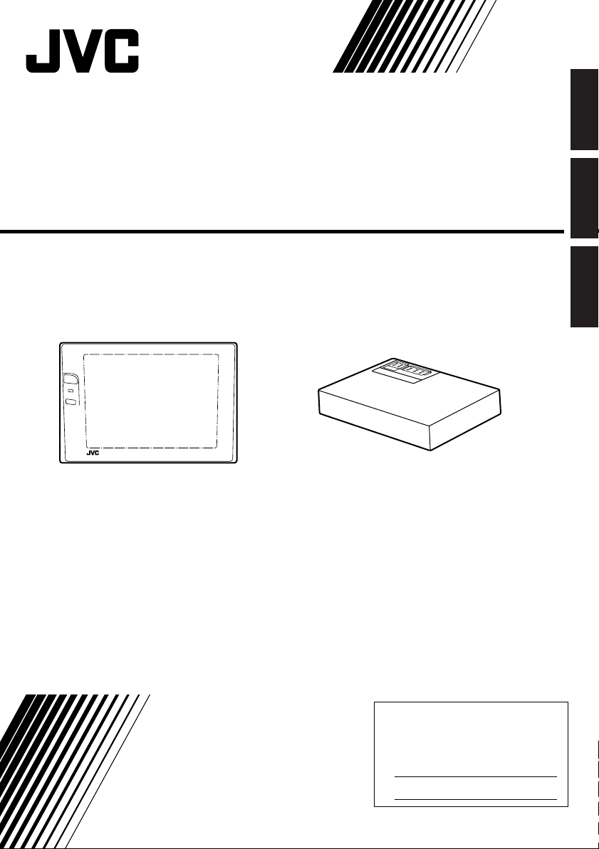
MOBILE COLOR MONITOR SYSTEM
SISTEMA DE MONITOR EN COLOR MÓVIL
SYSTÈME DE MONITEUR MOBILE EN COULEUR
KV-M65
KV-M65
MOBHE COLOR SYSTEMMOBHE COLOR SYSTEM
KV-M65
MOBILE COLOR MONITOR SYSTEM
Controller unit
Display unit
Unided de visualización
Unité d’affichange
Unidad controladora
Unité de commande
ENGLISH
ESPAÑOLFRANÇAIS
For installation and connections, refer to the
separate manual.
Para realizar la instalación y las conexiones,
consulte el manual separado.
Pour l’installation et les raccordements, se
référer au manuel séparé.
INSTRUCTIONS
MANUAL DE INSTRUCCIONES
MANUEL D’INSTRUCTIONS
*
This system cannot receive television broadcasts and is primarily
designed for use with a VCR. Use the separately sold mobile TV tuner
system KV-C1 for optional television broadcast reception.
*
Este sistema no puede recibir emisiones de televisión, y ha sido
diseñado principalmente para ser utilizado con una videograbadora.
Utilice el sistema de sintonizador de TV móvil KV-C1 vendido por
separado para reciber emisiones de televisión opcionales.
Ce système ne peut recevoir les emissions de télévision, et il est
*
essentiellement conçu pour l’utilisation avec un magnétoscope.
Utilisez le tuner avec système de tuner TV mobile KV-C1 vendu
séparément pour la réception optionnelle des émissions de télévision.
For customer Use:
Enter below the serial No. which is
located on the rear of cabinet. Retain
this information for future reference.
Model No. KV-M65
Serial No.
TQBX0223
[J]
Page 2
2
Safety points (Be sure to follow these points)
CAUTIONS
CAUTION
RISK OF ELECTRIC SHOCK
DO NOT OPEN
CAUTION: TO REDUCE THE RISK OF ELECTRIC SHOCK.
DO NOT REMOVE COVER (OR BACK).
NO USER-SERVICEABLE PARTS INSIDE.
REFER SERVICING TO QUALIFIED SERVICE PERSONNEL.
The lightning flash with arrowhead symbol, within an equilateral
triangle, is intended to alert the user to the presence of
uninsulated "dangerous voltage" within the product's enclosure
that may be of sufficient magnitude to constitute a risk of electric
shock to persons.
The exclamation point within an equilateral triangle is intended to
alert the user to the presence of important operating and
maintenance (servicing) instructions in the literature
accompanying the appliance.
WARNING:
TO PREVENT FIRE OR SHOCK
HAZARD, DO NOT EXPOSE THIS
UNIT TO RAIN OR MOISTURE.
CAUTION:
This monitor system should be used with DC 12V only.
T o prevent electric shocks and fire hazards, DO NOT use
any other power source.
This Class B digital apparatus meets all requirements of the
Canadian Interference–Causing Equipment Regulations.
“Cet appareil numérique de la classe B respecte toutes les
exigences du Règlement sur le matériel brouilleur du Canada.”
Warnings
• DO NOT INSTALL THE MONITOR IN A LOCATION
WHICH OBSTRUCTS DRIVING, VISIBILITY OR
WHICH IS PROHIBITED BY APPLICABLE LAWS
AND REGULATIONS.
• THERE MAY BE LEGAL REGULATIONS DEFINING THE PERMISSIBLE INSTALLATION LOCATIONS FOR THE DISPLAY UNIT WHICH DIFFER
BY COUNTRY OR BY STATE, BE SURE TO
INSTALL THE DISPLAY UNIT IN A CORRECT
LOCATION ACCORDING TO SUCH LAWS.
• DO NOT INSTALL THE MONITOR SYSTEM IN A
LOCATION WHICH OBSTRUCTS THE OPERATION OF AN AIR BAG.
• THE DRIVER MUST NOT OPERATE THE COLOR
MONITOR SYSTEM WHILE DRIVING.
OPERATING THE COLOR MONITOR SYSTEM
WHILE DRIVING MAY LEAD TO CARELESSNESS
AND CAUSE AN ACCIDENT.
* STOP YOUR VEHICLE IN A SAFE LOCATION WHEN
OPERATING THE TV TUNER SYSTEM.
• THE DRIVER MUST NOT WATCH THE TELEVISION OR VIDEOS WHILE DRIVING.
IF THE DRIVER WATCHES THE TELEVISION OR
A VIDEO WHILE DRIVING, IT MAY LEAD TO
CARELESSNESS AND CAUSE AN ACCIDENT.
Page 3

3
CAUTION :
Change or modifications not approved by JVC could void
user's authority to operate the equipment. This equipment has been tested and found to comply with the limits for a Class B digital device, pursuant to Part
FCC Rules. These limits are designed to provide reasonable protection against harmful interference in a residential installation. This equipment generates, uses, and
can radiate radio frequency energy and, if not installed
and used in accordance with the instructions, may cause
harmful interference to radio communications.
However, there is no guarantee that interference will not
occur in a particular installation. If this equipment does
cause harmful interference to radio or television reception, which can be determined by turning the equipment
off and on, the user is encouraged to try to correct the
interference by one or more of the following measures:
Reorient or relocate the receiving antenna.
Increase the separation between the equipment and
receiver.
Connect the equipment into an outlet on a circuit
different from that to which the receiver is connected.
Consult the dealer or an experienced radio/TV
technician for help.
15 of the
• WHEN LIGHTNING OCCURS, DO NOT TOUCH
THE ANTENNA WIRE OR THE TELEVISION.
TOUCHING THE ANTENNA WIRE OR THE TELEVISION UNDER SUCH CONDITIONS MAY CAUSE
ELECTROCUTION.
• KEEP THE MONITOR SYSTEM AT AN APPROPRIATE SOUND LEVEL WHILE DRIVING.
DRIVING WITH THE SOUND AT A LEVEL THAT
PREVENTS YOU FROM HEARING SOUNDS
OUTSIDE OF AND AROUND THE VEHICLE MAY
CAUSE AN ACCIDENT .
• ASK A TRAINED TECHNICIAN TO INSTALL THE
MONITOR SYSTEM.
INSTALLATION AND WIRING REQUIRE TRAINING
AND EXPERIENCE.
* TO BE SAFE, ASK THE SALES OUTLET WHERE
YOU PURCHASED THE MONITOR SYSTEM TO
PERFORM THE INSTALLATION.
• DO NOT LET THE MONITOR SYSTEM FALL OR
BE STRONGLY IMPACTED.
BE SURE TO NOT LET THE MONITOR SYSTEM
FALL OR BE STRONGLY IMPACTED SINCE THIS
MAY CAUSE A MALFUNCTION OR FIRE.
• DO NOT WATCH THE MONITOR WITH THE
ENGINE OFF.
WATCHING THE MONITOR WITH THE ENGINE OFF
WILL CONSUME BATTERY POWER AND MAY
PREVENT THE ENGINE FROM STARTING.
ENGLISH
ESPAÑOLFRANÇAIS
Page 4
4
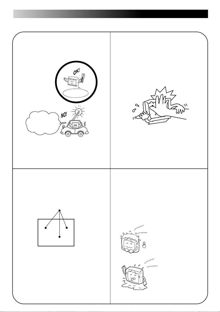
Cautions for the liquid crystal panel
• Do not leave the liquid crystal panel surface
facing upwards on top of the dashboard.
(storage temperature range: –20 °C to +80 °C
(–4 °F to +176 °F) )
+80°C
–20
–20°C to +80°C
During the summer,
temperatures can
reach as high as
100 °C (212 °F).
When the liquid crystal panel reaches high
temperatures or low temperatures, chemical
changes occur within the liquid crystal panel
which may cause malfunctions.
• There are red spots, blue spots and green
spots on the panel surface. This is a characteristic of liquid crystal panels and is not a
problem.
Spots
• Do not strongly impact the liquid crystal panel.
• When the temperature is very cold or very hot,
the image may not appear clearly or may
move slowly.
Also, movement of the image may seem to be
out of sync or the image quality may decline in
such environments. Note that this is not a
malfunction or problem.
(usage temperature range: 0 °C to +40 °C (32
°F to 104 °F) )
The liquid crystal panel is built with very high
precision technology and has at least 99.99%
effective image pixels. Be aware that on
0.01% of the panel there may be missing
pixels or constantly light pixels.
0 °C (32 °F) or colder
40 °C (104 °F) or hotter
Page 5

Thank you for purchasing a JVC product. Please read all instructions carefully before operation,
to ensure your complete understanding and to obtain the best possible performance from the
unit.
5
Table of Contents
Introduction to the Roles of the System Components ................6
How to Use the Monitor System
Controlling the Sound .................................................................9
Adjusting Brightness .................................................................12
Adjusting the Sound..................................................................16
Adjusting the Image..................................................................18
Connecting to External Devices................................................20
How to Best Use the Monitor System
Troubleshooting ........................................................................21
Maintenance .............................................................................22
Specifications............................................................................23
ENGLISH
ESPAÑOLFRANÇAIS
Page 6
6
Introduction to the Roles of the System
Components
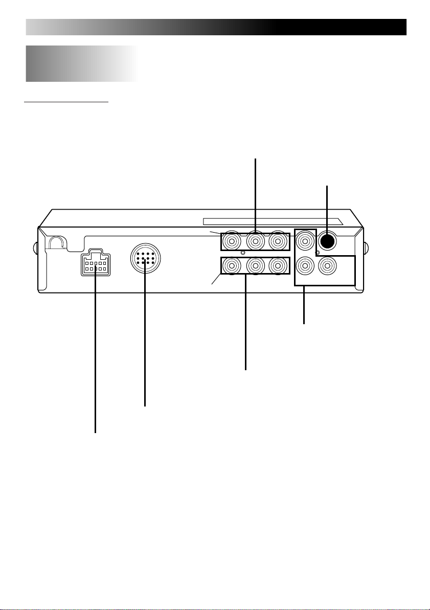
Controller unit
Terminal for connecting a mobile video
machine, video camera or other device
Not used at present
POWER
Terminal for connecting the power cord
DISPLAY UNIT
Terminal for connecting to the KV-M65 display unit
AV INPUT 1
VIDEO VIDEO
VIDEO
AV INPUT 2
L-AUDIO-R
L-AUDIO-R
Terminal for connecting a mobile video
machine, video camera or other device
L-AUDIO-R
Terminal for connecting a 2nd
monitor or car stereo audio
output
AV
OUTPUT
Page 7
Introduction to the Roles of the System Components (continued)
7
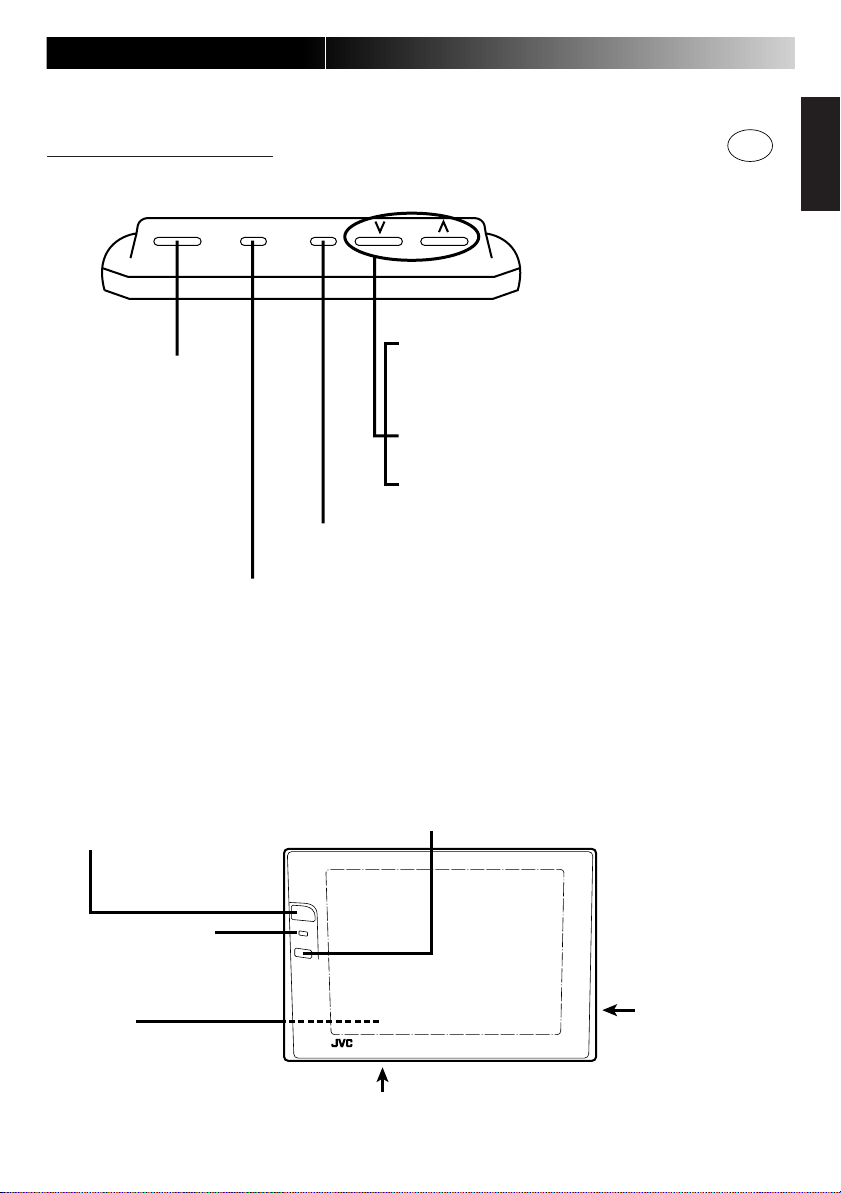
KV-M65 display unit
The numbers in the circles ( )
indicate the page on which an
explanation is provided in this manual.
POWER MODE MENU
Used to turn the power
source ON and OFF
Used to display, select and determine the various adjustments
(screen, menu).
Used to display the configuration screen for changing the input source and the various function menus.
Normally:
Changing the channel setting in the
upward or downward direction
(only when connected to the KV-C1)
When setting various menus:
Menu selection
When setting various adjustment modes:
Adjustment and switching
When set to the TV mode, channel numbers are shown. Note, however, that television broadcast reception requires connection to the separately sold KV-C1 mobile TV tuner system.
ENGLISH
ESPAÑOLFRANÇAIS
Remote sensor
Used when the JVC mobile TV tuner
system KV-C1 is connected
STAND BY (R), ON (G)
When the power is off ... red
When the power is on ... green
Speaker
(on the back side)
Screw holes are provided for attaching the monitor
stand (on the bottom side).
(1/4 inch unify screw, maximum length of 4.5 mm)
Dimmer sensor
This sensor automatically adjusts the screen brightness. (When
Auto Mode is set for the Dimmer Setting, the screen brightness is
automatically adjusted to one of 12 levels to suit the surrounding
brightness.)
KV-M65
MOBHE COLOR SYSTEMMOBHE COLOR SYSTEM
KV-M65
MOBILE COLOR MONITOR SYSTEM
Terminal for connecting
the cable from the
controller unit (on the
right side)
Page 8
8
BLACK BASS
CONT TREBLE
COLOR BALANCE
TI NT SURROUND
END
M
OVE
CURSOR
SELECT
M
ENU
18, 19 16, 17
*
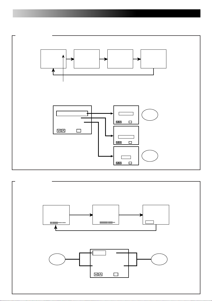
MODE button
When pressed for less than 2 seconds: The input source can be changed.
8
RGB
VIDEO 1
VIDEO 2
Television channel number
When pressed for 2 seconds or longer: The setting screens for various functions can be
displayed.
[ SPEAKER MODE ]
SPEAKER MODE
VIDEO
M
ODE
DI
MM
ER MODE
END
M
OVE
SELECT
M
ENU
CURSOR
STANDARD
NAVIGATION
M
UTE
M
ENU
[ RGB MODE ]
NAVIGATION
NO CONNECT
M
ENU
[ DIMMER MODE ]
AUTO
M
ANUAL
M
ENU
9 to 11
ENTERSELECT
ENTERSELECT
12 to 15
ENTERSELECT
MENU button
When pressed for less than 2 seconds: The adjustment screen display can be selected.
(The following diagram shows an example for the Speaker Output Setting on All Modes
and the Dimmer Setting on Auto Mode.)
VOLUME
30
BRIGHT
-10
[CH MODE]
AUTOMANUAL
When pressed for 2 seconds or longer: The menus for image and sound can be displayed.
When setting the menus: The Menu selection and adjustment can be decided.
* Displayed only when VIDEO1
or VIDEO2 is selected.
Page 9

Controlling the Sound
Selecting the volume of the built-in speakers
(The monitor system is set to STANDARD at the time of shipment from the factory.)
POWER MODE MENUPOWER MODE MENU
9
ENGLISH
ESPAÑOLFRANÇAIS
SPEAKER MODE
VIDEO
M
ODE
DI
MM
ER MODE
END
M
OVE
SELECT
M
ENU
CURSOR
MODE
SPEAKER MODE
VIDEO
M
ODE
DI
MM
ER MODE
END
M
OVE
SELECT
M
ENU
CURSOR
[ SPEAKER MODE ]
STANDARD
NAVIGATION
M
UTE
ENTERSELECT
M
ENU
MENU
Press the MODE button for 2 seconds or longer.
Select the SPEAKER MODE.
Press the MENU button.
Note
• If no operations are performed for a period of 30 seconds after pressing the MODE button:
The Menu configuration screen automatically disappears.
Page 10

10
POWER MODE MENUPOWER MODE MENU
[ SPEAKER MODE ]
STANDARD
NAVIGATION
M
UTE
ENTERSELECT
M
ENU
VOLUME
30
MENU
VOLUME
30
Sound level (0-60 levels)
Select STANDARD.
After the SPEAKER MODE screen disappears (occurs after about 10 seconds), press the MENU button for less
than 2 seconds and show the speaker volume level display.
Adjust the speaker volume level.
Note
• Relationship between the Speaker mode setting and the built-in speaker volume
Speaker mode setting
STANDARD Television sound – Video 1 sound Video 2 sound
NAVIGATION Not used at present. Please select either STANDARD or MUTE.
MUTE There is no sound output from the speakers
• Speaker output is monaural sound. (It is not heard as stereo sound.)
Built-in speaker volume
Television RGB Video 1 Video 2
Page 11

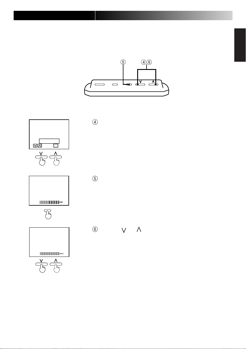
Adjusting the volume output level of the AV output terminal
POWER MODE MENUPOWER MODE MENU
Perform steps 1 to 3 on page 9.
Press the MODE button for 2 seconds or longer.
Select the SPEAKER MODE setting using the [ ] and [ ] buttons.
Press the MENU button.
Select MUTE.
[ SPEAKER MODE ]
STANDARD
NAVIGATION
M
UTE
ENTERSELECT
M
ENU
11
ENGLISH
ESPAÑOLFRANÇAIS
SOUND LEVEL
40
MENU
SOUND LEVEL
40
After the SPEAKER MODE setting screen disappears (occurs after about 10 seconds), press the MENU button for
less than 2 seconds and show the volume level display.
Adjust the volume output level of the AV output terminal.
Note
• When the SPEAKER MODE setting is on STANDARD:
The output level is fixed to the maximum of 60 and cannot be
adjusted. (See page 10 for more details.)
Page 12

12
Adjusting Brightness
For the automatic mode
(The monitor system is set to the Auto Mode at the time of shipment from the factory.)
Automatically adjusts the screen brightness to suit the brightness of the surrounding environment.
POWER MODE MENUPOWER MODE MENU
Press the MODE button for 2 seconds or longer.
SPEAKER MODE
VIDEO
M
DI
END
MM
ER MODE
M
OVE
CURSOR
MODE
ODE
SELECT
M
ENU
Note
• When END is selected, the system returns to the initial screen.
SPEAKER MODE
VIDEO
M
ODE
DI
MM
ER MODE
END
M
OVE
SELECT
M
ENU
CURSOR
[ DIMMER MODE ]
AUTO
M
ANUAL
ENTERSELECT
M
ENU
MENU
Select the DIMMER MODE.
Press the MENU button.
Page 13

[ DIMMER MODE ]
AUTO
M
ANUAL
DIMMER LEVEL
-55
MENU
13
ENGLISH
POWER MODE MENUPOWER MODE MENU
ESPAÑOLFRANÇAIS
Select AUTO.
ENTERSELECT
M
ENU
After the DIMMER MODE disappears (occurs after about
10 seconds), press the MENU button for less than 2 seconds and show the automatic dimmer (darkness level) display .
DIMMER LEVEL
-55
When set to 0, the brightness
does not change.
Use the [ ] or [ ] button to adjust brightness to the best
visibility at night.
Note
• When the adjustment is made to the best visibility at night, the
system automatically adjusts the level between the maximum
brightness and the brightness for the best visibility at night (minimum brightness).
(It is recommended that the setting be put between –40 and –60).
• When 0 is set, the value is fixed to the maximum level and the
brightness does not change.
Page 14

14
Adjusting Brightness
For the manual mode
The screen brightness can be adjusted manually.
POWER MODE MENUPOWER MODE MENU
Press the MODE button for 2 seconds or longer.
SPEAKER MODE
VIDEO
M
ODE
DI
MM
ER MODE
END
M
OVE
M
ENU
CURSOR
MODE
SPEAKER MODE
VIDEO
M
ODE
DI
MM
ER MODE
END
M
OVE
M
ENU
CURSOR
SELECT
SELECT
Note
• When END is selected, the system returns to the initial screen.
Select the DIMMER MODE.
[ DIMMER MODE ]
AUTO
M
ANUAL
ENTERSELECT
M
ENU
MENU
Press the MENU button.
Page 15
POWER MODE MENUPOWER MODE MENU
15
ENGLISH
ESPAÑOLFRANÇAIS
[ DIMMER MODE ]
AUTO
M
ANUAL
BRIGHT
-10
MENU
BRIGHT
-10
Select MANUAL.
Note
ENTERSELECT
M
ENU
• When MANUAL is selected in advance:
With the wireless remote controller, it is possible to set this level
directly using the Brightness button.
After the DIMMER MODE disappears (occurs after about
10 seconds), press the MENU button for less than 2 seconds and show the brightness display.
Use the [ ] or [ ] button to adjust the brightness to your
preferred level.
Page 16

16
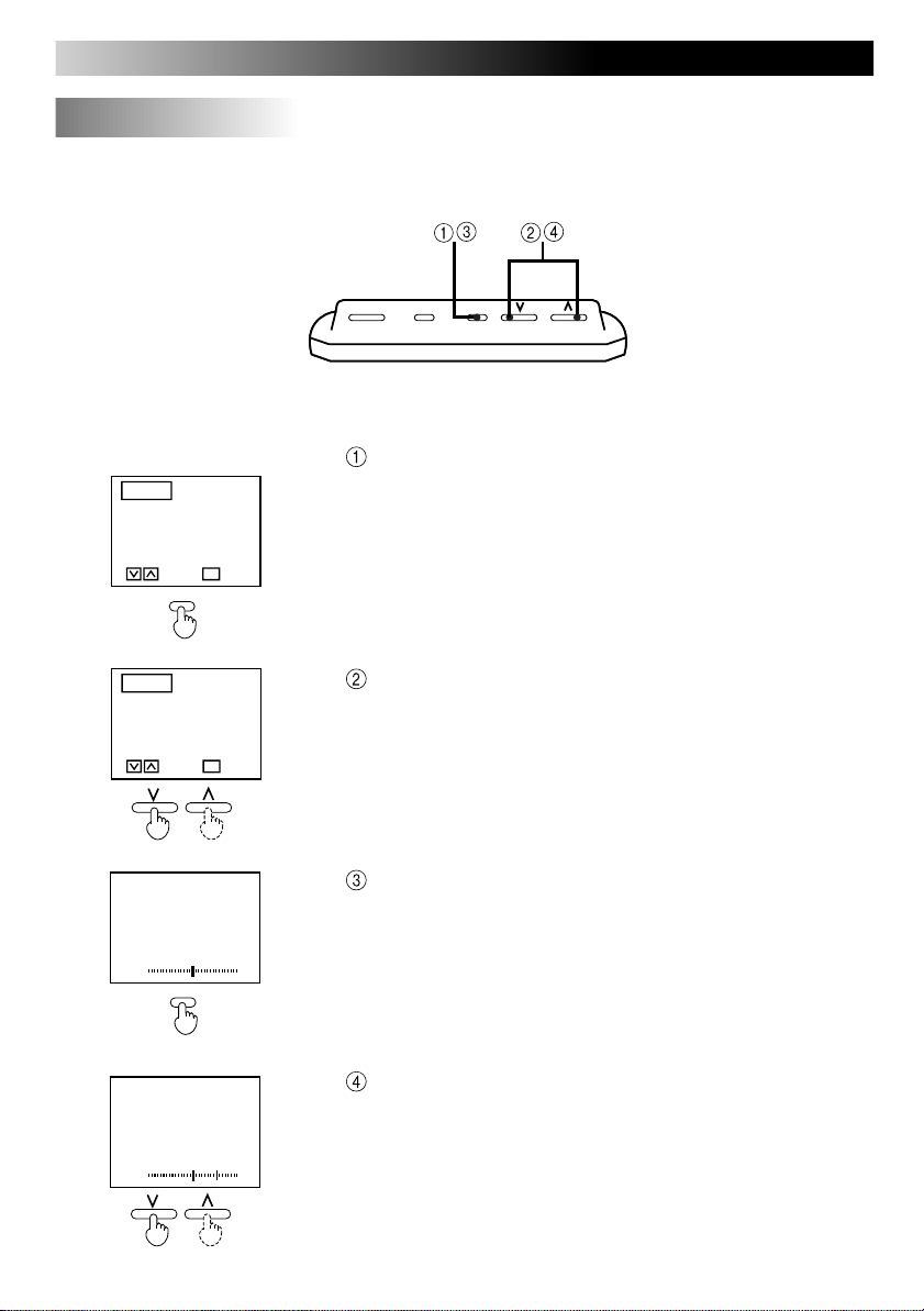
Adjusting the Sound
POWER MODE MENUPOWER MODE MENU
Example: Adjusting the bass level
BLACK BASS
CONT TREBLE
COLOR BALANCE
TI NT SURROUND
END
M
OVE
SELECT
M
ENU
CURSOR
MENU
BLACK BASS
CONT TREBLE
COLOR BALANCE
TI NT SURROUND
END
M
OVE
SELECT
M
ENU
CURSOR
BASS
0
MENU
BASS
+15
Press the MENU button for 2 seconds or longer.
Select BASS.
Press the MENU button.
Adjust the BASS level.
Note
• After 10 seconds passes:
The BASS Adjustment screen automatically disappears.
Note
• When END is selected, the system returns to the initial screen.
• Bass, Treble, Balance and Surround do not change in the case of a built-in speaker.
Page 17

17
BASS
+15
TREBLE
+15
BALANCE
+15
SURROUND ON
ENTERSELECT
M
ENU
Adjustment points (The bass, treble and balance can be adjusted from the setting screens)
BASS
BASS
-15
Bass is reduced. Bass is increased.
TREBLE
-15
Treble is reduced. Treble is increased.
(level of low tones)
TREBLE
(level of high tones)
ENGLISH
ESPAÑOLFRANÇAIS
BALANCE
-15
Sound output of the
right side is lowered.
SURROUND OFF
BALANCE
Balances the sound
output between the left
and right speakers
Sound output of the
left side is lowered.
SURROUND
ENTERSELECT
M
ENU
The feature gives a 3D
effect to the sound when
VIDEO1 or VIDEO2 is in
stereo format.
Page 18
18
Adjusting the Image
POWER MODE MENUPOWER MODE MENU
Example: Adjusting the black level
BLACK BASS
CONT TREBLE
COLOR BALANCE
TI NT SURROUND
END
M
OVE
SELECT
M
ENU
CURSOR
MENU
BLACK BASS
CONT TREBLE
COLOR BALANCE
TI NT SURROUND
END
M
OVE
SELECT
M
ENU
CURSOR
BLACK
0
MENU
Press the MENU button for 2 seconds or longer.
Note
• When END is selected, the system returns to the initial screen.
• For an RGB screen, only the Black level and Contrast are shown.
(Not used at present.)
• If no operations are performed for a period of 30 seconds after
pressing the MENU button
The Menu configuration screen automatically disappears.
Select BLACK.
Press the MENU button.
Adjust the Black level.
BLACK
+15
Note
• After 10 seconds passes
The Black Level adjustment screen automatically disappears.
Page 19

Adjustment points (Image features can be adjusted from the various setting screens)
BLACK
+15
CONT
+15
COLOR
+15
TINT
+15
19
BLACK LEVEL
BLACK
-15
Adjust the Black Level when there is an inversion of the black and white on the
screen or the screen appears too white due to an imbalance in the relationship
between the installation position of the monitor and eye level.
When the Black Level is
on the negative [–] side.
Makes the black portions of the
screen easier to see (Night
scenes, black hair, etc.)
When the Black Level is
on the positive [+] side.
CONTRAST
Normally set in the middle.
CONT
-15
Move to the right for more
contrast.
ENGLISH
ESPAÑOLFRANÇAIS
COLOR
COLOR
-15
Colors are less vivid. Colors are more vivid.
Setting to slightly
thicker colors
TINT
TINT
-15
Skin color has a reddish-purplish tint.
Setting for attractive
skin color
Skin color has a
greenish tint.
Page 20

20
Connecting to External Devices
Connection example 1
Mobile video machine or video camera (AV input 1) and car stereo (Audio output)
To car stereo
AV input 1
Controller unit
AV INPUT 1
DISPLAY UNIT
POWER
Connection example 2
Mobile video machine (AV input 1) and 2nd monitor (AV output)
AV INPUT 2
L-AUDIO-R
VIDEO
L-AUDIO-R L-AUDIO-R
VIDEO
VIDEO
AV
OUTPUT
Audio output
(Video terminal
not connected)
To 2nd monitor
AV input 1
Controller unit
POWER
VIDEO VIDEO
L-AUDIO-R
VIDEO
L-AUDIO-R L-AUDIO-R
AV INPUT 2
AV
OUTPUT
AV output
AV INPUT 1
DISPLAY UNIT
Note
• Refer to the installation manual for an explanation of how to make these connections.
• Since the connection cord varies depending on what external devices are connected, refer to the
video equipment manual as well.
• For connection of a mobile video machine or video camera:
When howling (a “pi” sound) occurs, take one of the following steps.
· Lower the volume on the monitor system
· Use earphones (when the camera has an earphone jack)
· Keep the monitor system and the camera microphone apart.
Page 21

Troubleshooting
Please check the following items one more time.
21
When this occurs
There are red, blue and
green spots on the
screen.
There is sound output,
but no video output
(only the channel
number is shown).
There is no sound from
the speakers.
The screen is dark.
The screen black and
white portions are
inverted.
The screen is too white.
The color is thin.
The tint is off.
Check these points
This is a characteristic of liquid crystal panels and is not a
problem.
(The liquid crystal panel is built with very
high precision technology and has at least
99.99% effective image pixels. Be aware
that on 0.01% of the panel there may be
missing pixels or constantly light pixels.)
• Is the parking brake connection wire (gray color) connected?
• The KV-M65 does not have a built-in TV tuner so no image is
shown when it is set to the TV mode.
• Was the parking brake lever pulled?
[Speaker Volume Adjustment]
Is the volume on the lowest level?
[Speaker Output Setting]
Is the setting on No Output?
[Brightness, Black Level and Contrast]
Are the settings properly adjusted?
[Color and Tint]
Are the settings properly adjusted?
Reference
page
–
Refer to
the
installation
manual
9 to 11
9 to 11
12 to 15
18, 19
18, 19
ENGLISH
ESPAÑOLFRANÇAIS
Page 22

22
Alcohol
Benzine
Thinner
Adhesive
tape
Pesticide
Wax
Tape
Maintenance
To prevent damage to the system exterior
Do not apply pesticides, benzine, thinner or other
volatile substances to the unit.
The cabinet surface primarily consists of plastic materials.
Do not wipe with benzine, thinner or similar substances because this will results in discoloration or
removal of the paint.
When a cloth with a cleansing chemical is used,
follow the caution points.
Do not leave the unit in contact with rubber or vinyl
products for long periods of time.
Do not use cleansers which have polishing granules because this could damage the surface of the
unit.
Clean dirt by wiping lightly with a soft cloth
When the unit is very dirty, wipe with a well-wrung cloth
dipped in a kitchen cleanser (neutral) thinned by water and
then go over the same surface with a dry cloth.
(Since there is the possibility of water drops getting inside
of the unit, do not directly apply cleanser to the surface.)
Wring well Wipe lightly
Go over the same surface
with a dry cloth
Kitchen cleanser thinned by water
Request
If water drops or similar wet substances get inside of the monitor via the liquid crystal panel surface, it may cause a malfunction.
Page 23

Specifications
23
Product type Mobile color monitor system
Power source voltage DC 14.4V (can be used within the range of 11V to 16V);
negative ground only
Usage temperature range 0°C to +40°C (32°F to 104°F)
Storage temperature range –20°C to +80°C (–4°F to +176°F)
Overall system
Liquid crystal panel 6-1/2”
Screen dimensions Width 13.3 cm (5-1/4”), height 10.0 cm (3-15/16”),
diagonal 16.6 cm (6-9/16”)
Number of pixels 224,640 pixels (234 vertical x 320 horizontal x 3)
Display method Transparent color filter format
Drive method TFT (thin film transistor) active matrix format
Visibility angle Left/right: ±45°, Upward: 40°, Downward: 20°
Light source Internal light (W-shaped, cold cathode fluorescent light)
Display unitController unit
Sound output 1 W
Speaker 4 cm (1-5/8”) round speaker (one)
Dimensions Width 18.8 cm (7-7/16”), height 12.8 cm (5-1/16”),
thickness 3.5 cm (1-7/16”)
Mass 600 g (1.4 lbs)
Connection terminals • Power, ground, parking brake, remote output connection
terminals (10 pin connector)
• Display unit connection terminal (13-pin DIN connector)
• AV input 1 and input 2 terminals
Video 1Vp-p(75Ω/RCA pin)
Audio 0.5Vrms (RCA pin)
• AV output terminal Video 1Vp-p(75Ω/RCA pin)
Audio 0 to 0.5Vrms(RCA pin)
(consecutive change supported by
sound level adjustment)
Dimensions Width 19.6 cm (7-3/4”), depth 14.2 cm (5-5/8”),
height 3.8 cm (1-1/2”)
Mass 800 g (1.8 lbs)
ENGLISH
ESPAÑOLFRANÇAIS
Page 24

VICTOR COMPANY OF JAPAN, LIMITED
KV-M65
EN, SP, FR.
Printed in Japan
0498MNMUBNMTS
 Loading...