

Page 1
SERVICE MANUAL
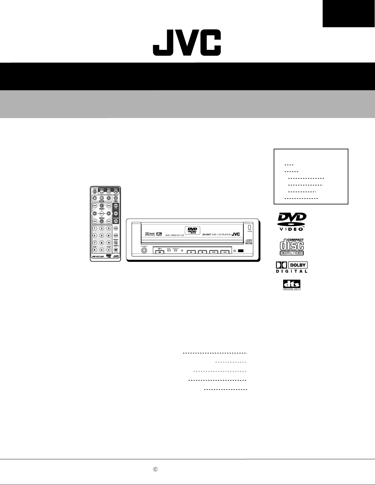
DVD/CD PLAYER
KV-DV7
KV-DV7
E
J
UF
UT
US
A
Area Suffix
Continental Europe
Northern America
China
Taiwan
Singapore
Australia
Contents
Safety precaution
Important for laser products
Disassembly method
Adjustment method
Description of major ICs
COPYRIGHT 2001 VICTOR COMPANY OF JAPAN, LTD.
1-2
1-3
1-4
1-11
1-12~17
No.49630
Apr. 2001
Page 2
KV-DV7
Safety precaution
!
!
Burrs formed during molding may be left over on some parts of the chassis. Therefore,
pay attention to such burrs in the case of preforming repair of this system.
Please use enough caution not to see the beam directly or touch it in case of an
adjustment or operation check.
1-2
Page 3
Important for laser products
KV-DV7
1.CLASS 1 LASER PRODUCT
2.DANGER : Invisible laser radiation when open and inter
lock failed or defeated. Avoid direct exposure to beam.
3.CAUTION : There are no serviceable parts inside the
Laser Unit. Do not disassemble the Laser Unit. Replace
the complete Laser Unit if it malfunctions.
4.CAUTION : The compact disc player uses invisible
laserradiation and is equipped with safety switches
whichprevent emission of radiation when the drawer is
open and the safety interlocks have failed or are de
feated. It is dangerous to defeat the safety switches.
VARNING : Osynlig laserstrålning är denna del är öppnad
och spårren är urkopplad. Betrakta ej strålen.
VARO : Avattaessa ja suojalukitus ohitettaessa olet
alttiina näkymättömälle lasersäteilylle.Älä katso
säteeseen.
5.CAUTION : If safety switches malfunction, the laser is able
to function.
6.CAUTION : Use of controls, adjustments or performance of
procedures other than those specified herein may result in
hazardous radiation exposure.
CAUTION
!
Please use enough caution not to
see the beam directly or touch it
in case of an adjustment or operation
check.
ADVARSEL : Usynlig laserstråling ved åbning , når
sikkerhedsafbrydere er ude af funktion. Undgå
udsættelse for stråling.
ADVARSEL : Usynlig laserstråling ved åpning,når
sikkerhetsbryteren er avslott. unngå utsettelse
for stråling.
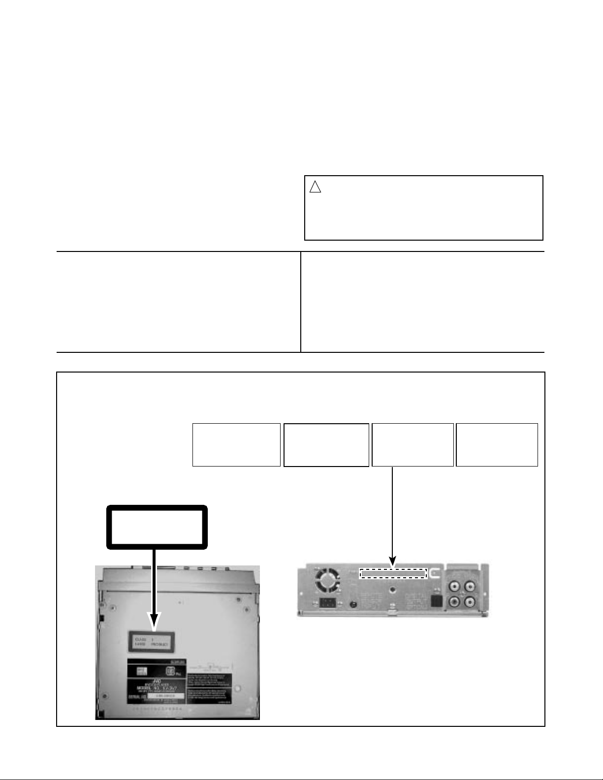
REPRODUCTION AND POSITION OF LABELS
WARNING LABEL
CLASS 1
LASER PRODUCT
DANGER : Invisibie laser radiation
when open and interlock or
defeated.
AVOID DIRECT EXPOSURE TO
BEAM (e)
VARO : Avattaessa ja suojalukitus
ohitettaessa olet alttiina
näkymättömälle lasersäteilylle.Älä
katso säteeseen. (d)
VARNING : Osynlig laserstrålning är
denna del är öppnad och spårren är
urkopplad. Betrakta ej strålen. (s)
ADVARSEL :Usynlig laserstråling
ved åbning , når
sikkerhedsafbrydere er ude af
funktion. Undgå udsættelse for
stråling. (f)
1-3
Page 4
KV-DV7
Disassembly method
< Main Body>
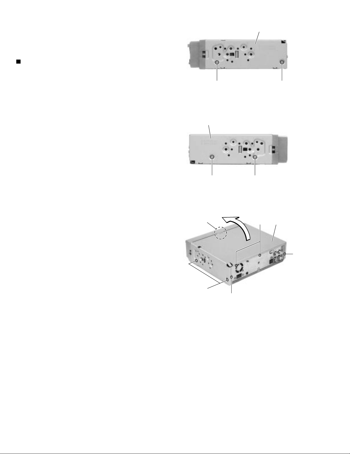
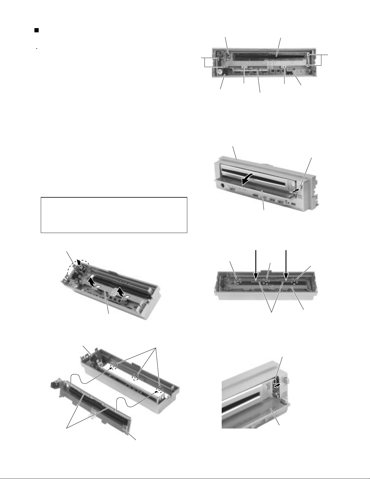
Removing the top cover (See Fig.1 to 3)
1.
Remove the seven screws A on both sides and
back of the body.
2.
Detach the rear part of the top cover upward and
release the joint a on the top side.
Top cover
AA
Fig.1
Top cover
AA
Fig.2
Joint a
A
A
Fig.3
A
Top cover
A
1-4
Page 5
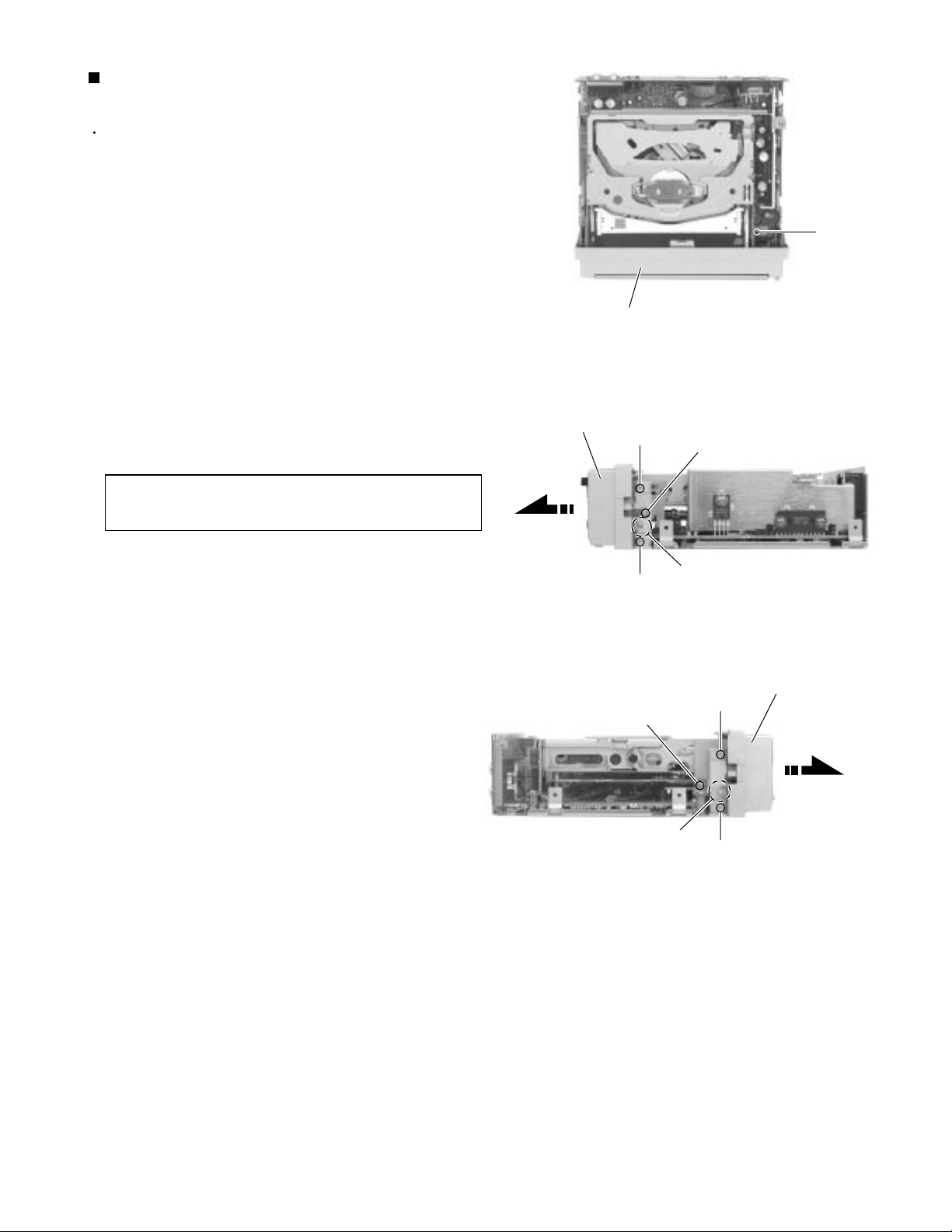
Removing the front panel assembly
(See Fig.4 to 6)
Prior to performing the following procedure, remove
the top cover.
1.
Remove the screw B attaching the ground on the
top of the body.
KV-DV7
2.
Remove the four screws C and two screws C'
attaching the front panel assembly on both sides of
the body.
3.
Release the two joints b of the front panel assembly
and the bottom chassis on both sides of the body
and remove the front panel assembly toward the
front.
The connector CN801 on the control switch board in
the front panel assembly will be disconnected from
the main board.
CAUTION:
When reassembling, attach the four
screws C and then the two screws C'.
Front panel assembly
Front panel assembly
C
C
C'
B
Fig.4
C'
Joint b
Fig.5
Front panel assembly
C
Joint b
Fig.6
C
1-5
Page 6
KV-DV7
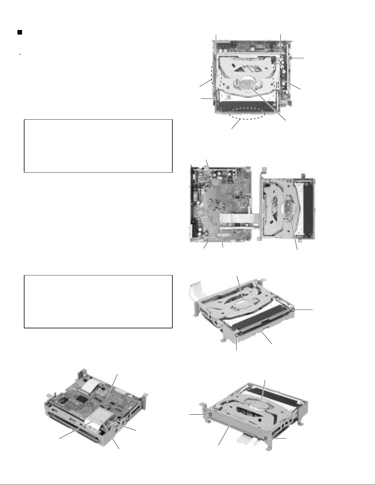
Removing the DVD mechanism
assembly (See Fig.7 to 11)
Prior to performing the following procedure, remove
the top cover and the front panel assembly.
1.
Remove the four screws D attaching the DVD
mechanism assembly on the top of the body.
2.
Remove the DVD mechanism assembly while
holding the part c on each side of the assembly.
CAUTION:
3.
Disconnect the card wire from connector CN721 and
CN701 on the main board andremove the DVD
mechanism assembly from the body.
To protect accuracy of the mechanism
bracket on the front of DVD mechanism
assembly, make sure to hold the part c
on each side of the DVD mechanism
assembly when removing or
reassembling.
Joint c
D
Do not hold the mechanism bracket.
Fig.7
Main board
DD
D
Joint c
DVD mechanism assembly
4.
Remove the two screws E attaching the DVD
mechanism bracket (1) on the front sideof the DVD
mechanism assembly.
5.
Remove the two screws F attaching the DVD
mechanism bracket (2) on the rear sideof the DVD
mechanism assembly.
CAUTION:
When reassembling the DVD
mechanism assembly, attach the cooling
rubber and the heat sink to the DVD
mechanism board as shown in Fig.11 to
make sure radiation of IC15 on the DVD
mechanism board (Fig.11).
DVD mechanism board
CN701
DVD mechanism assembly
CN721
E
DVD mechanism assembly
Fig.8
E
DVD mechanism bracket (1)
Fig.9
DVD mechanism assembly
1-6
Heat sink
IC15
Cooling rubber
F
F
DVD mechanism bracket (2)
Fig.10Fig.11
Page 7
KV-DV7
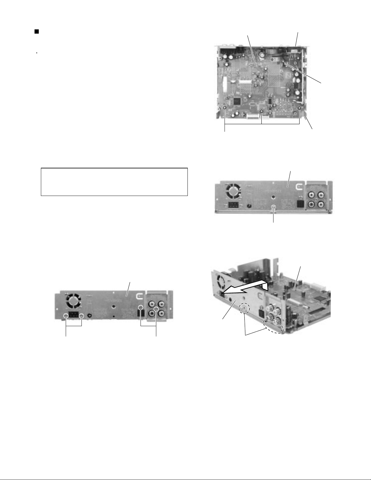
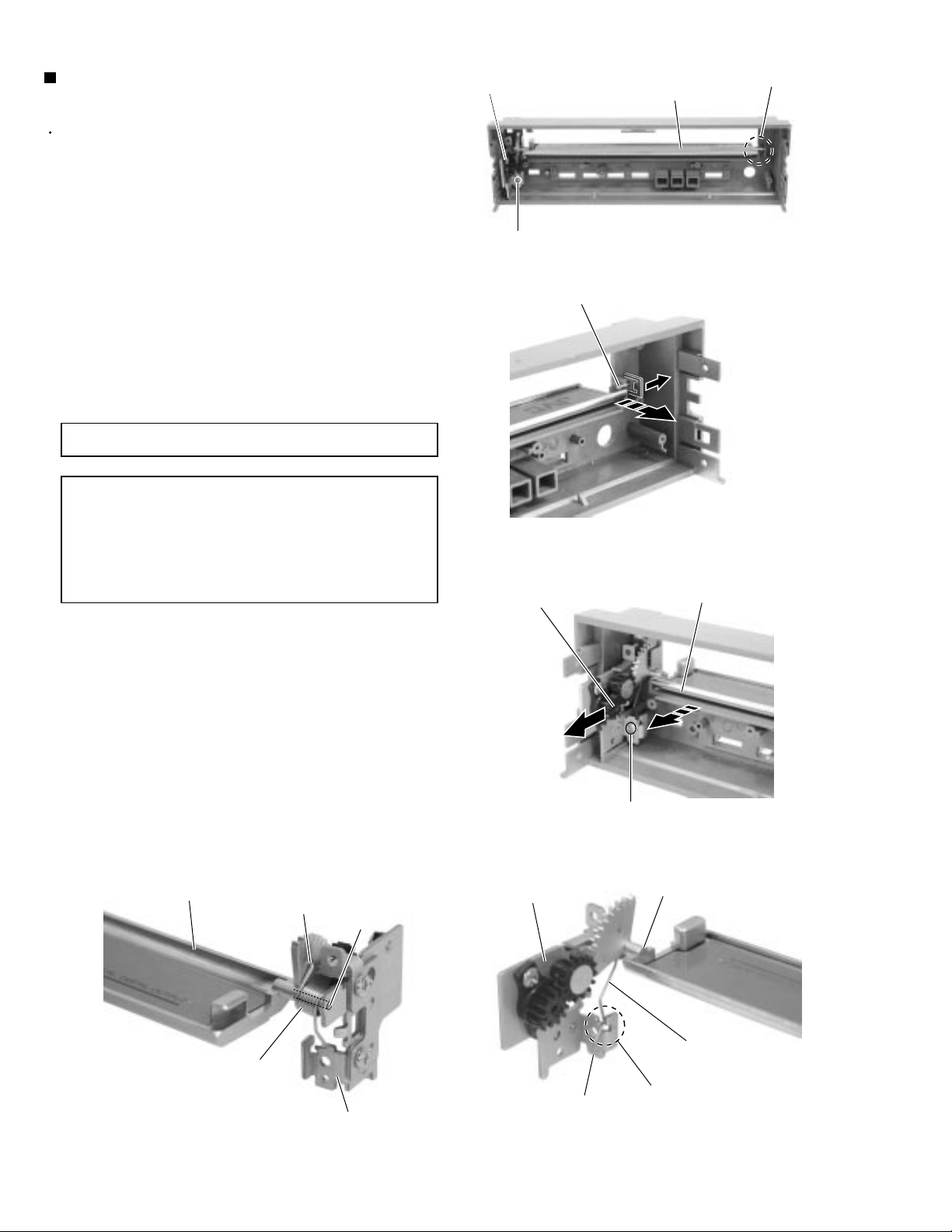
Removing the main board
(See Fig.12 to 15)
Prior to performing the following procedure, remove
the top cover, the front panel assembly and the DVD
mechanism assembly.
1.
Disconnect the wire from connector CN781 on the
main board.
2.
Remove the three screws G on the top of the body.
3.
Remove the screw H on the back of the body.
4.
Disengage the joint d in the lower right part of the
rear panel and remove the rear panel with the main
board (The fan assembly will be detached with the
rear panel).
CAUTION:
When reattaching, engage the joint c to
place the rear panel on the back of the
bottom chassis.
Main board
G
Rear panel
CN781
Bottom chassis
Fig.12
Rear panel
5.
Remove the two screws I and J attaching the main
board to the rear panel.
Rear panel
IJ
Fig.15
H
Fig.13
Main board
Rear panel
Joints d
Fig.14
1-7
Page 8
KV-DV7
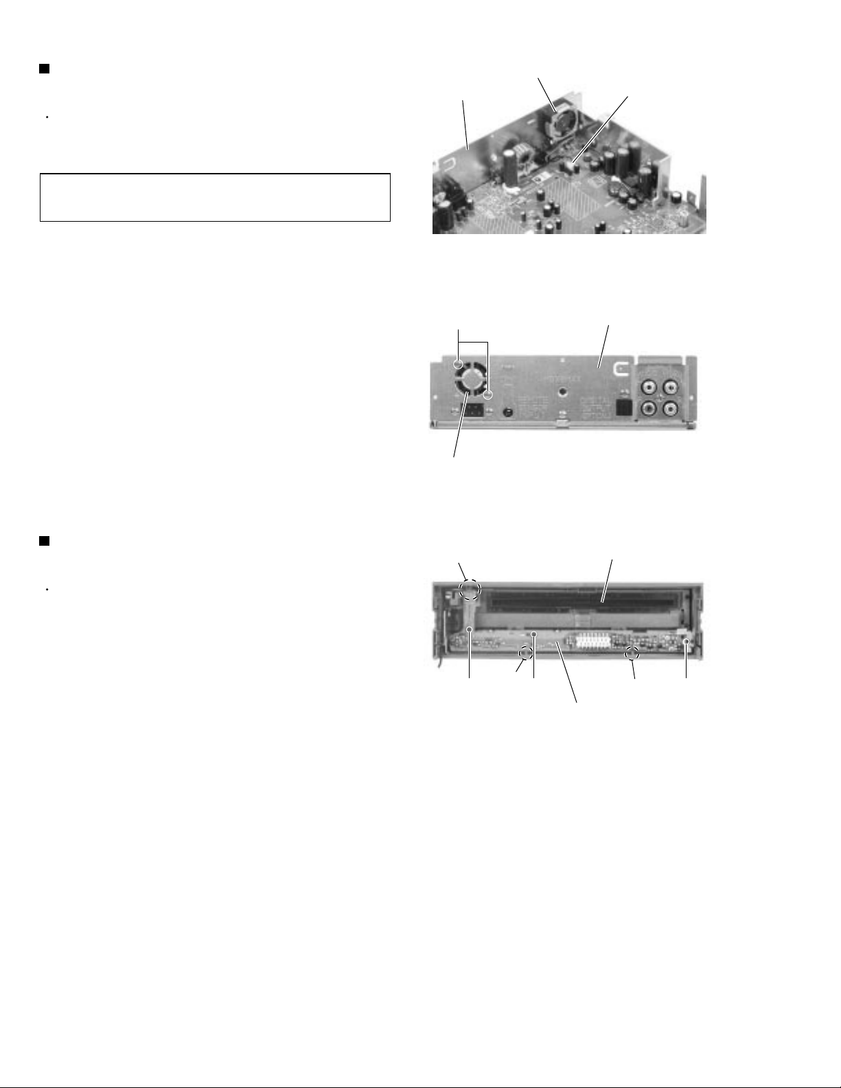
Removing the fan assembly
(See Fig.16 and 17)
Prior to performing the following procedure, remove
the top cover, the front panel assembly and the DVD
mechanism assembly.
REFERENCE:
1.
Disconnect the wire from connector CN781 on the
main board.
2.
Remove the two screws K on the back of the body.
It is not unnecessary to remove the main
board and the rear panel.
Rear panel
K
Fan assembly
Fan assembly
CN781
Fig.16
Rear panel
Fig.17
Removing the control switch board
(See Fig.18)
Prior to performing the following procedure, remove
the top cover and the front panel assembly.
1.
Remove the three screws L attaching the control
switch board on the back of the front panel
assembly.
2.
Disengage the three joints e of the front panel and
the control switch board.
Joint d
L
Joint e
Front panel assembly
L
Control switch board
Fig.18
Joint e
L
1-8
Page 9
KV-DV7
Replacing the DVD door flame
(See Fig.19 to 24)
Prior to performing the following procedure, remove
the front panel assembly and the control switch
board.
1.
Remove each button on the back of the front panel.
2.
Press the OPEN button on the front side of the front
panel to open the DVD door.
3.
Remove the six screws M attaching the DVD door
flame on the back of the front panel.
4.
Disengage the three joints f on the top of the DVD
door flame using a screwdriver (-) to pull out the
three bosses of the front panel. Peel off the two
adhesive tapes at the same time.
5.
Detach the bottom of the DVD door flame. Press the
lock lever on the front side of the front panel and
remove the DVD door flame from the gear.
CAUTION:
When reassembling, reattach the DVD
door flame to the front panel with the
two adhesive tapes while engaging the
three joints f.
Eject button
M
Reset button
Front panel
DVD door flame
MM
Control button
Power button
Fig.19
OPEN button
DVD door
Fig.20
M
Detach the lock lever from the front side, then from the gear.
DVD door flame (remove from bottom)
DVD door flame
Fig.22
Front panel
Bosses
Joint f
Insert a screwdriver.
Joint f
Adhesive tapes
Fig.21
Lock lever
Joint f
DVD door flame
Adhesive tapes
DVD door flame
DVD door
Fig.23Fig.24
1-9
Page 10
KV-DV7
Removing the DVD door
(See Fig.25 to 29)
Prior to performing the following procedure, remove
the front panel assembly, the control switch board
and the DVD door flame.
1.
Remove the screw N attaching the gear assembly
on the back of the front panel.
2.
Pull out the DVD door shaft from the joint g of the
DVD door and the front panel.
3.
Remove the DVD door with the gear assembly.
4.
Remove the spring through the notch h of the gear
assembly bracket and remove the DVD door from
the gear assembly.
CAUTION:
CAUTION:
Do not lose the spring.
Reattaching the DVD door, reattach the
spring through the notch h and hole i of
the gear assembly bracket, then
reassemble the DVD door and the gear
assembly. Reattach them to the front
panel.
Gear assembly
N
DVD door (Shaft)
Gear assembly
Joint g
DVD door
Fig.25
Fig.26
DVD door
1-10
DVD door
Spring
Hole i
Shaft
Bracket
Gear assembly
Bracket
M
Fig.27
DVD door
Spring
Notch h
Fig.28Fig.29
Page 11

Adjustment method
This model dose not have adjustment.
If you change printed circuit board or mechanism assembly, please
check as folow as next.
Test instruments required for checking
(1) Digital oscilloscope (100MHz)
(2) AM standard signal generator
(3) FM standard signal generator
(4) Stereo modulator
(5) Electric voltmeter
(6) Digital tester
(7) Monitor
(8) Test disc : VT-501 for DVD section
: CTS-1000 for CD section
Checking items
KV-DV7
(1) DVD section: Playback the test disc VT-501.
It should not have some noise on the audio signal or video signal.
(2) CD section : Playbcak the test disc CTS-1000.
It should not heve some noise on the audio signal.
1-11
Page 12
KV-DV7
Description of major ICs
UPD780058GC-250 (IC701) : Micon
1. Pin layput
2. Pin function (1/2)
Pin No.
1
2
3
4
5
6
7
8
9
10
11
12
13
14
15
16
17
18
19
20
21
22
23
24
25
26
27
28
29
30
31
32
33
34
35
36
EEPROM_CONT
37
38
39
40
61 ~ 80
Symbol
TEMP
AVSS
LCDCONT
D_OUT_MUTE
AVREF1
LCDDI/RXDO
LCDDO/TXDO
LCDCL/ASCK
JBUS_SI
JBUS_SO
JBUS_SCK
JBUS_CTRL+B
ANT_FM
D_HOST
D_FM
SCK
RDY_FM
/HOST_RST
NTSC/PAL
E.VOL_SCK
E.VOL_DO
E.VOL_STB
V_MUTE
A_MUTE
D_MUTE
LED_DISCIN
LED_DSP
LED_CD/DVD
LED_DVD
EEPROM_DO
VSS1
EEPROM_DI
EEPROM_CLK
FANCONT
LCDCE
60 ~ 41
1 ~ 20
I/O
I
-
-
-
-
I
I
-
O
-
I
O
O
I
O
I
-
O
I
O
I
O
O
O
O
O
O
O
O
I
O
O
O
O
-
-
-
-
-
O
-
-
-
40 ~ 21
Function
Templature sensor
Non connect
Non connect
Audio ground
LCD control
DIgital out mute
Anarog reference voltage
Communication for JIG LCD or PC
Communication for JIG LCD or PC
Communication for JIG LCD or PC
J-BUS serial input
J-BUS serial output
J-BUS serial clock input
Power supply for J-BUS control
Communication for DVD mechanism
Communication for DVD mechanism
Communication for DVD mechanism
Communication for DVD mechanism
Communication for DVD mechanism
Communication for DVD mechanism
NTSC/PAL control (H:PAL L:NTSC)
E. volume serial clock output
E. volume data output
E. volume strobe output
Video mute output
Audio mute output
Audio mute input
LED output for slot
LED output for Real sonic or Remocon
LED output for CD/DVD
LED output for DVD
Non connect
Ground1
Non connect
Non connect
Non connect
Fan control
Non connect
Non connect
LCD chip select
1-12
Page 13

2. Pin function (2/2)
KV-DV7
Pin No.
41
42
43
44
45
46
47
48
49
50
51
52
53
54
55
56
57
58
59
60
61
62
63
64
65
66
67
68
69
70
71
72
73
74
75
76
77
78
79
80
Symbol
LCDRST
JBUS_I/O
S1_CONT
SIDE_BRAKE
HEADPHONE
REMOCON_SEL
SB_SEL_V
SB_SEL_OP
LCD/PC_SEL
ADDRESS_SEL
NTSC/PAL_SEL
VSYNC
POWER_CONT
+7V_CONT
+5V_CONT
LED_CONT
PLAY_REMOTE
LINE_IN
CD_DET
RESET
J-INT
P.SAVE2(BATT)
P.SAVE1(ACC)
FM_INT
REMOCON
KEY_INT
VSS0
VDD1
X2
X1
IC
XT2
XT1
VDD0
AVREF0
ANI0
ANI1
ANI2
ANI3
ANI4
I/O
-
I/O
I
I
I
I
I
I
I
I
O
O
O
O
O
I
I
O
I
I
I
I
I
I
-
O
O
I
I
I
I
I
Function
Non connect
J-BUS I/O
S1 control
Side brake detection
Headphone detection
Remocon code select
Side brake select
Side brake select
Communication select
Address select on J-BUS
NTSC/PAL select
Power supply control
Mechanism power supply +7V control
Mechanism power supply +5V control
Power supply control od LED & Remocon
Play remote output
LINE IN control
Non connect
Reset
J-BUS initialize
Battery detection
ACC detection
DVD mechanism communication
Remocon input
KEY_INT
Setting to input for common use
Power supply1
Connect to X'tal
Connect to X'tal
Non connect
Power supply
Power supply 0
Referencew voltage
Key input 0
Key input 1
Key input 2
Key input 3
Key input 4
1-13
Page 14

KV-DV7
BA4901A-V3 (IC911) : Regulator
1. Pin layout
2.Pin Function
123456789
9V
VCC-B
VCC-C
ACC5V
ACC.IN
CDBV
VDD5V
CTRL
MEMORY.IN
101112
AJ
10V
GND
Pin No. Symbol Descriptions
1
2
3
4
5
VCC-C
VCC-B
ACC5V
ACC.IN
VDD5V
To be connected with the collector of PNP.
To be connected with the base of PNP.
A voltage supply for ACC block.
Control of the COMP output by inputting voltage.
Output voltage level is 5.7V, and max output current is 100mA.
This voltage supply is for microcomputer. Whenever backup voltage
supply is connected, the output keeps on running.
6
9V
This output voltage is 9.0V, and max output current is 500mA.
This voltage supply for AUDIO.
7
CDBV
This output voltage is 8.0V, and max output current is 1A
This voltage supply for CD.
10
8
9
CTRL
MEMORY.IN
10V
Output selector of CD, AUDIO, ILM and Vcc-B.
To be connected with the BACKUP of car
This output voltage is 10V, and max output current is 500mA.
Output voltage is adjustable.
11
AJ
Putting a resistance between ILM and AJ or between AJ and GND males
ILM output voltage adjustable.
12
GND
Connect to GND
LM2596S-ADJ-W (IC951) : Regulator
1. Pin layout 2. Block diagram
CURRENT
SOURCE
BIAS
15
FEEDBACK
R1=2.5k
3.3V, R2 = 4.2k
5V, R2 = 7.5k
12V, R2 = 21.8k
ADJ, R2 = 0
R1 = OPEN
1-14
R2
1.235V
REFERENCE
ACTIVE
CAPACITOR
AMP
OP AMP
REGULATOR
GM
2.5V
2.5V
ON/OFF
START
UP
COMP.
FREQ. SHIFT
150kHz
OSC.
LATCH
CURRENT
LIMIT
RESET
220mV
COMP.
COMP.
DRIVER
THERMAL
LIMIT
200mV
3A
SWITCH
~
VIN
OUTPUT
GND
Page 15

IC-PST9333U-X (IC741) : Regulator
1. Pin layout
KV-DV7
2. Block diagram
NC 1
GND 2
4 Vcc
3 VOUT
Vcc 4
NC 1
3. Pin function
Pin No.
1
2
3
4
Symbol
NC
GND
VOUT
Vcc
Function
Non connect
GND terminal
Reset signal output terminal
Vcc terminal/Voltage detect terminal
NJM2267X-X (IC301) : Video amp.
1. Pin layout 2. Block diagram
3 VOUT
2 GND
V+
7
VIN1
GND
VSAG1
VOUT1
1
2
3
4
8
7
6
5
VIN2
V+
VSAG2
VOUT2
VIN 2
VIN 1
8
1
CLAMP CLAMP
20k
20k
6.2dB
Amp
6.2dB
Amp
2.2k
2.2k
75
DRIVER
75
DRIVER
SAG TERMINAL
SAG TERMINAL
2
GND
750
750
5
6
4
3
VOUT2
VSAG2
VOUT1
VSAG1
1-15
Page 16

KV-DV7
NJM4580V-X (IC101,IC151) : Ope amp.
1. Pin layout & Block diagram
A OUTPUT
1
8
A
A-INPUT
2
7
B
A+INPUT
V-
3
4
6
5
RPM6938-V4 (IC801) : Remocon reseiver
1. Block diagram
V+
B OUTPUT
B-INPUT
B+INPUT
PQ05RD21 (IC961) : Regulator
1. Block diagram
Vin 1
IC
3
GND
2 Vo
4 Vc
AMP
I/V
conversion
PD
magnetic shield
BPF Detector
for
trimming
circuit
TA78L05F-X (IC971) : Regulator
1. Pin layout
AGC
Vcc
22k
Comp
Vcc
ROUT
GND
TC7SET08F-X (IC511) : Regulator
2. Truth table1. Pin layout
45
123
A
B
Y
L
L
L
L
H
L
H
L
L
H
H
H
1-16
123
Page 17

TC9260F-X (IC131) : E. volume
1. Pin layout 2. Pin function
KV-DV7
1
Vss
2
OUT
3
IN
4
LD1
5
LD2
CS
CK
6
7
8
A-GND
3. Block diagram
OUT 2
16
15
14
13
12
11
10
9
VDD
OUT
IN
LD1
LD2
A-GND
STB
DATA
Vss
1
Pin No.
1
2
3
4
5
6
7
8
9
10
11
12
13
14
15
16
VDD
16
Symbol
Vss
L-OUT
L-IN
L-LD1
L-LD2
L-GND
CS
CK
DATA
STB
R-GND
R-LD2
R-LD1
R-IN
R-OUT
VDD
Function
Digital ground terminal
Volume output terminal
Volume input terminal
Tap out terminal for loudness(1)
Tap out terminal for loudness(2)
Analog ground terminal
Chip select terminal
Clock input terminal
Data input terminal
Strobe input terminal
Analog ground terminal
Tap output terminal for loudness(2)
Tap output terminal for loudness(1)
Volume input terminal
Volume output terminal
Power supply terminal
15 OUT
L-ch
VOLUME
IN 3
LD1 4
LD2 5
A-GND 6
CS 7
CK 8
L-ch
LATCH
DATA DECODER STB GENERATOR
SHIFT REGISTER (13bit)
R-ch
LATCH
14 IN
13 LD1
12 LD2
11 A-GND
10 STB
9 DATA
R-ch
VOLUME
1-17
Page 18

KV-DV7
VICTOR COMPANY OF JAPAN, LIMITED
MOBILE ELECTRONICS DIVISION
PERSONAL & MOBILE NETWORK BUSINESS UNIT. 10-1,1Chome,Ohwatari-machi,Maebashi-city,371-8543,Japan
(No.49630)
200104
Page 19

Block diagram
KV-DV7
VIDEO_OUT
6
CN701 CN721
LT
RT
5
DVD
MECHA
UNIT
NTSC/PAL,D_MUTE
IEC958
4
RDT_FM,D_FM,ATN_FM
D_HOST,HOST_RST,SCL
CN781
FAN
FAN CONT
3
IC301
VIDEO
AMP
IC101
DAC LPF
IC511
DIGITAL
OUT
V_OOUT1,V_OUT2
L_CH
R_CH
L_CH,R_CH
D_OUT_MUTE
IC701
MICON
IC741
RESET
IC131
H.P.
E.VOL
E.VOL_STB
E.VOL_DO
E.VOL_SCK
RESET
LOUT
ROUT
LED_CD/VCD
LED_REMOCON
LED_DVD
LED_DISC IN
IC151
H.P.
AMP
ANI0
ANI1
ANI2
REMOCON
REMIN
CN891
CN801
REG
HEAD_PHONE
HP.L_CH
HP.R_CH
J861
ANI0
ANI1
ANI2
J301
CN901
J801
LED
MATRIX
KEY
MATRIX
2
IC801
REMOCON
REMOCON
1
BC
DE
F
G
HA
I
2-1
Page 20

Standard schematic diagrams
Stanard chematic diagram
Main section
KV-DV7KV-D V7
J301
QNN0400-002
6
CN701
QGF1013F1-20X
B701
0
B702
0
5
4
CN721
QGF0503F4-08X
L706
NQR0007-002X
B707
0
B708
0
B710
0
B711
0
B713
0
B714
0
B715
0
B716
0
B717
0
B718
0
B719
0
B720
0
B721
0
B722
0
B723
0
B724
0
B725
0
B726
0
B727
0
B728
0
0
0
B993
B994
3
2
1
/HOST_RST
RDY_FM
ATN_FM
D_HOST
NTSC/PAL
DAC5V
D_FM
SCK
D_MUTE
CN781
QGA2001C1-02
C111
4.7/25
C211
4.7/25
10/16
C783
IC971
TA78L05F-X
C973 C972
100/10 0.1 10/16
C113
470p
C114
560p
100k
180p
C112
R111
R211
IC101
NJM4580M-X
100k
Q781
2SD1994A/RS/-T
Q782
UN2111-X
R114R113R112
2.2k2.2k2.2k
R214R213R212
2.2k2.2k2.2k
C213
180p
C212
560p
10k
470p
C214
R216 R215
R782
10
0.01
R781
C782
470
UDZ12B-X
10/16
C781
D781
R309
C305
1.5
IC301
NJM2267V-X
C303
1.5
75
R301
C971
10k
R116
4.7k
R115
C218
470p
4.7k
0.1
C102
C115
C118
100p
C116
R117
470p
C101
100/10
10
R101
R118
22k
22k
R119
C117C217
47/6.347/6.3
22k
R219
R218
22k
C215
100p
2.2k
47/6.3
C741
R741
HEAD_PHONE
P.SAVE2
P.SAVE1
SCK
REMOCON
C706
470P
4.7K
4.7K
4.7K
4.7K
4.7K
R726
R728
R730
R734
R732
ANI0
ANI1
ANI2
ANI3
ANI4
4.7/25
C216
4.7/25
IC-PST9333U-X
C705
R737
C703
R727
R729
R731
R733
R735
10k10k
R122R222
R217
IC741
X701
QAX0414-001Z
C704
22P
R120
470
100
Q121
2SD1048/6-7/-X
Q221
2SD1048/6-7/-X
R220
470
100
47k
R742
22P
0
0.1
10K
10K
10K
10K
10K
C306
2200/10
220/10
0.047
C301
C302
C304
2200/107575 0
R121
6.8k
R221
6.8k
0.1
D741
1SS355-X
C742
RESET
47K
R725
0.1
C702
4.7k
R701
10
R314
R303
0
1K1K
R305R304
R302
DAP202K
TH701
NAD0021-103X
R313
C141
C142
4.7/25
R143
E.VOL_SCK
D121
E.VOL_DO
E.VOL_STB
R243
C242
0.22
C241
4.7/25
47K
47k
R723
R795
7V_CONT
5V_CONT
LED_CONT
PWR_CONT
PLAY_REMOTE
IC701
UPD780058GC-250
2.2K
2.2K
R702
R703
D_OUT_MUTE
R142
R141
0.22
470K
56k
C143
1200p
6.8k
6.8k
R241
470K
330
330
330
R736
R704
R705
D_FM
D_HOST
ATN_FM
C144
100K100K
R161R261
R162
4.7K
4.7/25
10
R131
0.1
C131
C132
100/10
IC131
TC9260F-X
4.7/25
C243
R242
1200p
56k
330
2.2K
2.2K
R706
R707
R708
/HOST_RST
RDY_FM
SCK
C261 C161
C244
R262
4.7K
R714
47K
R716
47K
R718
47K
R720
47K
D_MUTE
2.2k
R139
E.VOL_STB
R138
E.VOL_DO
2.2k
R137
E.VOL_SCK
2.2k
R791
NTSC/PAL
10k
R164
R163
18K
C163
6.8K
150P
C162
100P
220P 220P
C262
100P
R263
6.8K
R264
220/10
0.1
R151
C152
IC151
NJM4580M-X
C263
150P
220/10
18K
L701
NQL011K-4R7X
C701
100/6.3
47K
R799
C164
10
R165R265
C151
100/10
C264
2SD1048/6-7/-X
2SD1048/6-7/-X
2SD1048/6-7/-X
2SD1048/6-7/-X
R171 R172
39 22
0.010.01
1k10K
C171C271
Q272 Q172
UN2111-X
100/16
UDZ11B-X
C401
D403
R175
1k
R174
1K
Q171Q271
R274
1K
R275
1k
R272R271
Q401
2239
2SA1037AK/RS/-X
Q403
2.2K
R402
Q402
UN2211-X
UN2111-X
22K
R401
Q941
Q942
UN2211-X
HP_L-CH
AGND
HP_R-CH
HEAD_PHONE
ANI0
ANI1
ANI2
RESET
REMIN
D401
1SS355-X
D171
DAP202K-X
LED_CONT
IC961
PQ05RD21
L953
QQLZ032-4R7
D911
DAP202K-X
220/10
C957
0
0
0
10/16
C916
QGB1218J2-16
220/10
C956
0
1.5k
R917
R918
2SB1322/RS/-X
CN801
470/25
C955
100K
R915
Q911
R920
2.7k
100/10
220/10
0.1
0.1
C961
C963
C962
C964
5V_CONT
R173
B171
R273
470P
C172
470P
C272
C917
2200/6.3
Q931
R932
Q932
UN2211-X
Q921
2SC2412K/R/-X2SA1037AK/RS/-X
47K
R931
27K
22K
R916
P.SAVE2
P.SAVE1
CN891
QGB1218K1-16
R924
47K
2SA1037AK/RS/-X
Q922
R923
R921
39K
68K
R922
2.2K
R951R952
220/10
C915
2.2K470
IC911
BA4901A-V3
R919
IC951
LM2596S-ADJ-W
L951L952
QQL45AK-470QQLZ032-4R7
C954
22/10
0.01
C913
C914
22K
L802
NQR0202-001X
L861
L863
L862
0.015
0.1
C953
100K
R914
NQR0007-002X
NQR0007-002X
NQR0007-002X
R953
7V_CONT
C912
0.1
560/25
D951
22K
RB81L-20-X
C951
C952
D_OUT_MUTE
R912
R911
9.1k
1K
5.1k
R913
C911
47/16
2.2/50
J861
QNS0026-001
IC801
RPM6938-V4
R802
471
R801
C801
10/10
0
HP_L-CH
AGND
HP_R-CH
PWR_CONT
S841
NSW0039-001X
B815
D814
R814
S831
TC7SET08F-X
NQL011K-4R7X
REMIN
REMOCON
0
SML-310LT/MN/-X
820
Q813
DTC114EKA-X
NSW0039-001X
IC511
L511
R803
120
R805
10k
D901
1N5404-TU-15
D813
560
R813
S832
R807
QQR0703-001
2200/16
C901
D812
SML-310LT/MN/-X
R812
DTC114EKA-X
NSW0039-001X
L901
C511
R804
120
10k
D801
SML-310LT/MN/-X
820
DTC114EKA-X
S821
NSW0039-001X
Q811Q812Q814
R841
R511
1SS355-X
1k
0.1
D811
QNZ0487-002
10
C501
R811
IC501
100/6.3
B901
SML-310LT/MN/-X
820
DTC114EKA-X
0.1
C502
0
S822
NSW0039-001X
R821
R831R851
1k1k
S811
NSW0039-001X
CN901
QNZ0506-001
D821
D822
220
SML-310LT/MN/-X
SML-310LT/MN/-X
S812
NSW0039-001X
R822
J801
QNS0185-001
D823
SML-310LT/MN/-X
D824
SML-310LT/MN/-X
D825
SML-310LT/MN/-X
D826
SML-310LT/MN/-X
330
BC
DE
2-2
VIDEO SIGNAL
AUDIO SIGNAL
F
G
Parts are safety assurance parts.
When replacing those parts make
sure to use the specified one.
HA
I
Page 21

KV-DV7
AV decoder section
6
5
4
3
2
1
BC
DE
F
G
HA
I
2-3
Page 22

KV-DV7KV-D V7
VIDEO encoder section
6
5
4
3
2
1
BC
DE
2-4
F
G
HA
I
Page 23

Audio decoder section
6
5
KV-DV7
4
3
2
1
BC
DE
F
G
HA
I
2-5
Page 24

KV-DV7KV-D V7
Analog output section
6
5
SHIELD
4
3
2
1
BC
DE
2-6
F
G
HA
I
Page 25

KV-DV7
DVD servo control section
6
5
4
3
2
1
BC
DE
F
G
HA
I
2-7
Page 26

Printed circuit boards
Main board (Forward side) Main board (Reverse side)
KV-DV7KV-D V7
R196
B710
B720
R713
LCDCE
C751
R772
R511
R767
C293
R295
B718
C172
C761
C762
R761
C502C511
R329
B726
LCDDA
R120
Q411
Q331
R332R333
B724
B725
R794
R737
C703
LCDCONT
Q121
R734
R220
C164
C306
R314
J301
R302
R309
C326
R322
C741
R311
C324
C304
R344
C305
Q311
Q342
R342
R304
D311
R343
Q341
R313
R325 R326
J341
R341
R303
R305
R312
Q312
L302
C302
C301
C303
R301
C325
R324
R323
C321
C322
C323
R321
B723
B722
B721
R704
R736
R705 R706
R707 R708
R741
C704
X701
C705
R726
R728
R730
R732
R221
C216
B_OUT
LCDCL
R271
R171
R714
C171
R122
R331
B703
B702
DAC5V
R716
Q412
R222
R265
B704
R718
R117
C116
R703
R720
R165
Q221
R217
R121
R411
R412
D402
C331
B727
B728
D701
R722
C702
R702
C264
IC501
D121
C501
C193
R195
B705
B706
B707
B701
B712
B708
B709
R793
R724
R799
R712
R792
R753
R752
R791
R751
C272
R272
C271
R172
IC511
6
IC501
J301
C216
C303
R735
R701
R806
TH701
C116
C331
B994
CN701
R723
R795
R717
R719
R721
R715
IC701
C264
R275
D171
Q172
R175
Q171
C741
IC301
C306
C301
C325
C321
C323
CN721
B993
R805
R742
D741
C742
IC741
X701
R727
R729
R731
R733
C164
C304
B301
C305
5
4
C326
IC321
J341
C324
B991
PP2
3
Q272
IC751
C501
Q271
R174
B711
R274
R197
L511
D902
F901
Q191
IC181
R191 R192
R193 R194
C191
B731
R725
B992
CN891
C701
IC761
C192
R738
C194
C111
IC101
R216
C292
R111
R211
C211
C973
R116
D901
CN761
R292
R215
C218
D761
C291
R261
C262
D191
C118
R115
R297
R293
C263
R263
C181
Q291
C102
R262
R264
C261
C971
C244
B995
C115
R294
D401
C215
C161
R291
R101
C144
R118
C101
C243
CN999
R242
R218
R243
C242
C117
IC131
C152
C401
R241
C901
C217
C241
J801
L901
L951
R953
C953
C141
B51
B61
R141
C142
C143
R142
R143
C76
C131
C75
VR61
R161
IC151
R162
R163
C162
R164
D76
C163
C151
C952
IC951
D801
R807
CN901
PP1
C791
C783
Q781
Q601
C917
C951
C61
C51
IC71
C77
C62
R62
Q61
C601
CN781
C915
C781
C957
C956
C79
C52
R52
Q51
D72D75 D73D74
CN71
L952
C78
VR51
C73
D77
Q71
D71
L953
C961
C955
D903
C912
C913
R911
B901
C911
C911
IC911
R919
R914
C914
Q911
C964
C962
C916
C963
IC961
C919
R912
R913
R915
R917
R918
R920
IC911
Q911
C916
R916
Q941
Q942
IC961
C963
C71
C912
D911
C961
R911
Q932
R932
C955
VR51
C917
C913
CN901
R781
R603
Q791
Q931
R931
C915
R924
Q921
C951
D951
R952
L953
L952
C71
Q71
R72
D71
CN71
D791
R804
C401
Q403
Q402
C117
C217
R402
R401
C101
R768
C113
C214
C213
C971
R771
D901
C901
R770
C114
Q401
R213
C212
IC971
R803
PP1
CN781
D781
D782
C781
Q602
R923
Q922
C957
R951
C954
C956
R73
C79
C78
C73
C74
R71
Q51
D72
D73
R922
L951
C782
J801
C783
Q781
R782
Q782
R601
D601
R602
R604
R605
Q601
R921
R61
R51
C61
C51
C75C77
R63
C63
B73
D74
B72
R53
C53
C76
B71
R131
Q61
VR61
D75
D76
C131
R151
C141
C132
C144
L901
D403
R119
R219
C241
C244
C151
CN999
R214
R181
CN891
R773
C181
C291
R114
R710
R709
R774
R296
R113
C211
R711
R298
C111
C973
C972
R766
L701
CN761
C194
R765
C183
R212
R198
C292
R764
C182
C112
R112
B715
B717
C192
B716
LCDRST
R769
R763
R273
B171
R173
D902
C191
C701
R762
R182
B713
B714
B719
2
1
Front board (Forward side) Front board (Reverse side)
J861
C861
C862
L861
L863
R821
L862
Q811
C802
F
IC801
S822
S841
S812
D821
D826
S832
S831
D825
BC
D824
S821
D823
D814
D813
D812
D811
D822
S811
J861
W1
DE
R811
R812
Q812
R813
Q813
Q814
R814
G
CN801
C801
B814
B815
R851
R841
R822
HA
R831
IC801
R801
R802
I
2-8
Page 27

KV-DV7
Frontend board
(Forward side) (Reverse side)
6
5
4
3
2
1
BC
DE
F
G
HA
I
2-9
Page 28

KV-DV7KV-D V7
Backend board (Forward side) Backend board (Reverse side)
6
5
4
3
2
1
BC
DE
2-10
F
G
HA
I
Page 29

PARTS LIST
[ KV-DV7 ]
* All printed circuit boards and its assemblies are not available as service parts.
KV-DV7
- Contents -
Exploded view of general assembly and parts list
Electrical parts list
Packing materials and accessories parts list
Area suffix
E ----------- Continental Europe
J -------------- Northern America
UF --------------------------- China
UT -------------------------- Taiwan
US --------------------- Singapore
A ------------------------- Australia
3-2
3-5
3-8
3-1
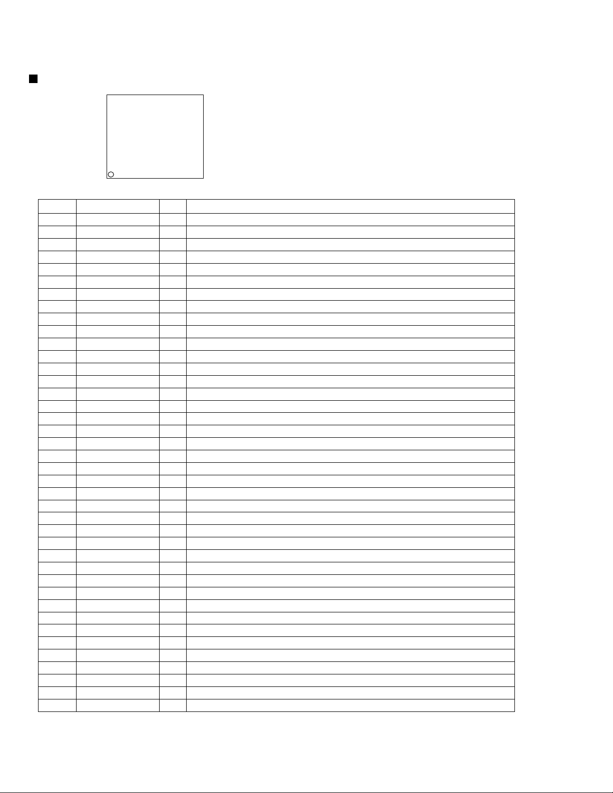
Page 30

KV-DV7
Exploded view of general assembly and parts list
Block No.
M
M
1
M
TYPE 1
62
49
34
16
61
23
63
49
56
43
16
15
49
58
57
53
17
16
50
71
55
TYPE 2
67
66
68
70
69
50
50
15
10
20
65
2
14
20
13
9
21
9
64
33
32
4
19
7
3
1
19
7
64
5
8
6
64
3-2
22
41
18
31
Main board
18
45
39
37
22
22
44
38
26
40
24
60
48
35
27
25
54
42
51
29
47
59
28
28
30
12
46
49
36
11
52
Page 31

Item Parts number Parts name Area
Parts list (General assembly)
M1MM
)
)
A
1 BDL1130-001MSV MECHA FRONTEND 1
2 BDL1130-001MA BACKEND P.W.B. A1
BDL1130-001ME BACKEND P.W.B. E1
BDL1130-001MJ BACKEND P.W.B. J1
BDL1130-001MUF BACKEND P.W.B. UF1
BDL1130-001MUS BACKEND P.W.B. US1
BDL1130-001MUT BACKEND P.W.B. UT1
3 LV10475-001A MECHA BKT(F
4 LV10476-001A MECHA BKT(R
5 LV42133-001A HEAT SINK 1
6 LV42205-001A COOLING RUBBER 1
7 QYSDSP2604Z SCREW 2 ME.BKT(F)+MECHA
8 QYSDSP2604Z SCREW 1 ME.BKT(F)+H.SIN
9 QYSDSP2604Z SCREW 2 ME.BKT(R)+MECHA
10 LV10473-001A TOP COVER 1
11 LV32512-002A B.CHASSIS ASSY 1
12 LV32498-001A INSULATOR 1
13 QUQ110-2011BJ FFC WIRE 1
14 QUQ105-0811BJ FFC WIRE 1
15 QYSDST2604N SCREW 4 TOP.CO.+B.CHASS
16 QYSDST2604N SCREW 3 TOP.CO.+REAR BK
17 QYSDST2604N SCREW 1 B.CHASS+REAR BK
18 LV42387-001A SPECIAL SCREW 3 B.CHASS+MAIN PW
19 QYSDSP2604Z SCREW 2 ME.BKT(F)+B.CHA
20 QYSDSP2604Z SCREW 2 ME.BKT(R)+B.CHA
21 QYSDSP2604Z SCREW 1 M.BKT(R)+IC H.S
22 QYSDSP2004Z SCREW 4 B.CHASS+F.PANEL
23 QYSDSP2004Z SCREW 1 EARTH BKT+ME.BK
24 LV42150-001A DAMPER BKT ASSY 1 D.BKT+GEAR+DAMP
25 QZW0066-001 DAMPER 1
26 QYSDSP2003Z SCREW 1 DAMPER+DAMP.BKT
27 LV42380-001A BRACKET 1
28 QYSDSP2003Z SCREW 2 DAM.BKT+BRACKET
29 LV42596-001A EARTH BRACKET 1
30 QYSDSP2004Z SCREW 1
31 LV10477-001A FRONT PANEL 1
32 LV32520-001A P.HOLDER ASSY 1
33 LV42135-002A BLIND 1
34 LV32515-001A DISC GUIDE 1
35 LV20946-001A DOOR 1 1/2/3/4/5/6
36 LV32494-001A LOCK LEVER 1
37 LV32491-001A PUSH BUTTON 1
38 LV32492-001A RELEASE BUTTON 1
39 LV32513-001A POWER BUTTON 1
40 LV32495-001A REMOCON LENS 1
41 LV32496-001A FINDER 1
42 LV32505-001A DOOR PLATE 1
43 LV32493-001A EJECT BUTTON 1
KV-DV7
Block No.
Q'ty Description
1
1
3-3
Page 32

KV-DV7
)
)
)
Parts list (General assembly)
Item Parts number Parts name Area
A
44 LV42021-001A JVC BUDGE 1
45 LE40564-002A MARK 1
46 LV42138-001A T.SPRING(D0OR
47 LV42139-001A T.SPRING(LOCK
48 LV42140-001A COM.SP(RELE.BU
49 VKZ4777-003 MINI SCREW 6 FRONT+REAR
50 VKZ4777-003 MINI SCREW 3 F.PANEL+SW.PWB
51 QYSDSF2006Z SCREW 1 F.PANEL+DAM.BKT
52 LV32503-001A NAME PLATE J1
LV33089-001A NAME PLATE A1
LV33090-001A NAME PLATE US1
LV33090-002A NAME PLATE UT1
LV33090-003A NAME PLATE UF1
LV32847-001A NAME PLATE E1
53 LV32489-001A REAR BRACKET 1
54 LV32571-001A RE.IC HEAT SINK 1
55 QYSDSP2604Z SCREW 2 REAR+POWER CN
56 QYSDSF3008Z SCREW 1 REAR+PIN JACK
57 QYSDST2614Z SCREW 2
58 QYSDSF3008Z SCREW 1 REAR+ OPT.OUT
59 QYSPSPD2610Z SCREW 2 H.SINK(IC)+IC
60 QYSPSPD2608Z SCREW 1 H.SINK(RE)+REG
61 QAR0145-001 FAN MOTOR 1
62 LV41675-001A FAN BRACKET 1
63 LV42500-001A EARTH BRACKET 1
64 VHD1420-1 SCREW 4
65 LV42620-001A SHIELD PLATE J1
66 LV32489-002A REAR BRACKET 1
67 QYSPST2604Z SCREW 2
68 QAR0145-002 FAN MOTOR 1
69 LV42629-001A FAN BRACKET 1
70 QZW0074-001 DAMPER 1
71 LV40847-002A SPACER 1
Q'ty Description
1
1
1
TYPE 1
TYPE 1
TYPE 1
TYPE 1
TYPE 2
TYPE 2
TYPE 2
TYPE 2
TYPE 2
TYPE 2
Block No. M1MM
3-4
Please change parts written as type 2 at the same time when you exchange fan motor by the set to
serial number until 086*****.
(FAN MOTOR,REAR BRACKET,SCREW,FAN BRACKET,DAMPER and SPACER)
Page 33

KV-DV7
)
Electrical parts list (Main board)
Item
A
C 101 QEKJ1AM-107Z E CAPACITOR 100MF 20% 10V
C 102 NCB31CK-104X C CAPACITOR
C 111 QEKJ1EM-475Z E CAPACITOR 4.7MF 20% 25V
C 112 NCS31HJ-181X C CAPACITOR
C 113 NCS31HJ-561X C CAPACITOR
C 114 NCS31HJ-471X C CAPACITOR
C 115 NCS31HJ-101X C CAPACITOR
C 116 QEKJ1EM-475Z E CAPACITOR 4.7MF 20% 25V
C 117 QEKJ0JM-476Z E CAPACITOR 47MF 20% 6.3V
C 118 NCS31HJ-471X C CAPACITOR
C 131 QEKJ1AM-107Z E CAPACITOR 100MF 20% 10V
C 132 NCB31CK-104X C CAPACITOR
C 141 QEKJ1EM-475Z E CAPACITOR 4.7MF 20% 25V
C 142 NCB31AK-224X C CAPACITOR
C 143 NCB31HK-122X C CAPACITOR
C 144 QEKJ1EM-475Z E CAPACITOR 4.7MF 20% 25V
C 151 QEKJ1AM-107Z E CAPACITOR 100MF 20% 10V
C 152 NCB31CK-104X C CAPACITOR
C 161 NCS31HJ-221X C CAPACITOR
C 162 NCS31HJ-101X C CAPACITOR
C 163 NCS31HJ-151X C CAPACITOR
C 164 QERF1AM-227Z E CAPACITOR 220MF 20% 10V
C 171 NCB31HK-103X C CAPACITOR
C 172 NCS31HJ-471X C CAPACITOR
C 211 QEKJ1EM-475Z E CAPACITOR 4.7MF 20% 25V
C 212 NCS31HJ-181X C CAPACITOR
C 213 NCS31HJ-561X C CAPACITOR
C 214 NCS31HJ-471X C CAPACITOR
C 215 NCS31HJ-101X C CAPACITOR
C 216 QEKJ1EM-475Z E CAPACITOR 4.7MF 20% 25V
C 217 QEKJ0JM-476Z E CAPACITOR 47MF 20% 6.3V
C 218 NCS31HJ-471X C CAPACITOR
C 241 QEKJ1EM-475Z E CAPACITOR 4.7MF 20% 25V
C 242 NCB31AK-224X C CAPACITOR
C 243 NCB31HK-122X C CAPACITOR
C 244 QEKJ1EM-475Z E CAPACITOR 4.7MF 20% 25V
C 261 NCS31HJ-221X C CAPACITOR
C 262 NCS31HJ-101X C CAPACITOR
C 263 NCS31HJ-151X C CAPACITOR
C 264 QERF1AM-227Z E CAPACITOR 220MF 20% 10V
C 271 NCB31HK-103X C CAPACITOR
C 272 NCS31HJ-471X C CAPACITOR
C 301 QERF1AM-227Z E CAPACITOR 220MF 20% 10V
C 302 NCB31CK-473X C CAPACITOR
C 303 QCZ0205-155Z ML C CAPACITOR 1.5MF
C 304 QETM1AM-228 E CAPACITOR 2200MF 20% 10V
C 305 QCZ0205-155Z ML C CAPACITOR 1.5MF
C 306 QETM1AM-228 E CAPACITOR 2200MF 20% 10V
C 401 QEKJ1CM-107Z E CAPACITOR 100MF 20% 16V
C 501 QEKJ0JM-107Z E CAPACITOR 100MF 20% 6.3V
C 502 NCB31CK-104X C CAPACITOR
C 511 NCB31CK-104X C CAPACITOR
C 701 QEKJ1AM-107Z E CAPACITOR 100MF 20% 10V
C 702 NCB31CK-104X C CAPACITOR
C 703 NCB31CK-104X C CAPACITOR
C 704 NDC31HJ-220X C CAPACITOR
C 705 NDC31HJ-220X C CAPACITOR
C 706 QCBB1HK-471Y C CAPACITOR 470PF 10% 50V
C 741 QEKJ0JM-476Z E CAPACITOR 47MF 20% 6.3V
C 742 NCB31CK-104X C CAPACITOR
C 781 QEKJ1CM-106Z E CAPACITOR 10MF 20% 16V
C 782 NCB31HK-103X C CAPACITOR
C 783 QEKJ1CM-106Z E CAPACITOR 10MF 20% 16V
Parts number Parts name Area
Remarks
Block No. 01
Item
A
C 801 NBE21AM-106X E CAPACITOR
C 802 NQR0202-001X FERRITE BEADS AGND-DGND(SGND
C 901 QEZ0337-228 E CAPACITOR 2200MF
C 911 QEKJ1HM-225Z E CAPACITOR 2.2MF 20% 50V
C 912 QEKJ1CM-476Z E CAPACITOR 47MF 20% 16V
C 913 QERF1AM-227Z E CAPACITOR 220MF 20% 10V
C 914 NCB31HK-103X C CAPACITOR
C 915 QERF1AM-227Z E CAPACITOR 220MF 20% 10V
C 916 QEKJ1CM-106Z E CAPACITOR 10MF 20% 16V
C 917 QETN0JM-228Z E CAPACITOR 2200MF 20% 6.3V
C 919 NCB31CK-104X C CAPACITOR
C 951 QEMT1EM-567 E CAPACITOR 560MF 20% 25V
C 952 NCB31CK-104X C CAPACITOR
C 953 NCB31CK-104X C CAPACITOR
C 954 NCB31EK-153X C CAPACITOR
C 955 QEMT1EM-477 E CAPACITOR 470MF 20% 25V
C 956 QERF1AM-227Z E CAPACITOR 220MF 20% 10V
C 957 QERF1AM-227Z E CAPACITOR 220MF 20% 10V
C 961 QEKJ1AM-107Z E CAPACITOR 100MF 20% 10V
C 962 NCB31CK-104X C CAPACITOR
C 963 QERF1AM-227Z E CAPACITOR 220MF 20% 10V
C 964 NCB31CK-104X C CAPACITOR
C 971 QEKJ1CM-106Z E CAPACITOR 10MF 20% 16V
C 972 NCB31CK-104X C CAPACITOR
C 973 QEKJ1AM-107Z E CAPACITOR 100MF 20% 10V
CN701 QGF1013F1-20X CONNECTOR
CN721 QGF0503F4-08X CONNECTOR CM
CN781 QGA2001C1-02 2P PLUG ASSY
CN801 QGB1218J2-16 CONNECTOR
CN891 QGB1218K1-16 CONNECTOR
CN901 QNZ0506-001 CAR CONNECTOR
D 121 DAP202K-X D.TRANSISTOR
D 171 DAP202K-X D.TRANSISTOR
D 401 1SS355-X DIODE
D 403 UDZ11B-X Z.DIODE
D 741 1SS355-X DIODE
D 781 UDZ12B-X Z DIODE
D 801 1SS355-X DIODE
D 811 SML-310LT/MN/-X LED DVD
D 812 SML-310LT/MN/-X LED CD/VCD
D 813 SML-310LT/MN/-X LED
D 814 SML-310LT/MN/-X LED DISC IN
D 821 SML-310LT/MN/-X LED EJECT
D 822 SML-310LT/MN/-X LED POWER
D 823 SML-310LT/MN/-X LED PLAY
D 824 SML-310LT/MN/-X LED STOP
D 825 SML-310LT/MN/-X LED F.SKIP
D 826 SML-310LT/MN/-X LED B.SKIP
D 901 1N5404-TU-15 DIODE
D 911 DAP202K-X D.TRANSISTOR
D 951 RB081L-20-X SB DIODE
IC101 NJM4580V-X IC
IC131 TC9260F-X IC
IC151 NJM4580V-X IC
IC301 NJM2267V-X IC
IC501 QNZ0487-002 OPTICAL JACK
IC511 TC7SET08F-X IC
IC701 UPD780058GC-250 IC(MAICON)
IC741 IC-PST9333U-X IC
IC801 RPM6938-V4 RM.RECEIVER
IC911 BA4901A-V3 IC
IC951 LM2596S-ADJ-W IC
IC961 PQ05RD21 IC
Parts number Parts name Area
Remarks
3-5
Page 34

KV-DV7
Q
Q
Q
Q
Q
Q
Q
Q
Q
Q
Q
Q
Q
Q
Q
Q
Q
Q
Q
Q
Q
Q
Electrical parts list (Main board)
Item
A
IC971 TA78L05F-X IC
J 301 QNN0400-002 PIN JACK
J 801 QNS0185-001 3.5 JACK
J 861 QNS0026-001 JACK
L 511 NQL011K-4R7X INDUCTOR
L 701 NQL011K-4R7X INDUCTOR
L 861 NQR0007-002X FERRITE BEADS HP L-CH
L 862 NQR0007-002X FERRITE BEADS HP R-CH
L 863 NQR0007-002X FERRITE BEADS HP AGND
L 901 QQR0703-001 CHOKE COIL
L 951 QQL45AK-470 INDUCTOR
L 952 QQLZ032-4R7 INDUCTOR
L 953 QQLZ032-4R7 INDUCTOR
PP 1 QZW0010-001 STYLE PIN
R 101 NRSA63J-100X MG RESISTOR
R 111 NRSA63J-104X MG RESISTOR
R 112 NRSA63J-222X MG RESISTOR
R 113 NRSA63J-222X MG RESISTOR
R 114 NRSA63J-222X MG RESISTOR
R 115 NRSA63J-472X MG RESISTOR
R 116 NRSA63J-103X MG RESISTOR
R 117 NRSA63J-471X MG RESISTOR
R 118 NRSA63J-223X MG RESISTOR
R 119 NRSA63J-223X MG RESISTOR
R 120 NRSA63J-101X MG RESISTOR
R 121 NRSA63J-682X MG RESISTOR
R 122 NRSA63J-103X MG RESISTOR
R 131 NRSA63J-100X MG RESISTOR
R 141 NRSA63J-474X MG RESISTOR
R 142 NRSA63J-563X MG RESISTOR
R 143 NRSA63J-682X MG RESISTOR
R 151 NRSA63J-100X MG RESISTOR
R 161 NRSA63J-104X MG RESISTOR
R 162 NRSA63J-472X MG RESISTOR
R 163 NRSA63J-682X MG RESISTOR
R 164 NRSA63J-183X MG RESISTOR
R 165 NRSA63J-102X MG RESISTOR
R 171 NRSA63J-390X MG RESISTOR
R 172 NRSA63J-220X MG RESISTOR
R 173 NRSA63J-0R0X MG RESISTOR
R 174 NRSA63J-102X MG RESISTOR
Parts number Parts name Area
121 2SD1048/6-7/-X TRANSISTOR
171 2SD1048/6-7/-X TRANSISTOR
172 2SD1048/6-7/-X TRANSISTOR
221 2SD1048/6-7/-X TRANSISTOR
271 2SD1048/6-7/-X TRANSISTOR
272 2SD1048/6-7/-X TRANSISTOR
401 2SA1037AK/RS/-X TRANSISTOR
402 UN2211-X TRANSISTOR
403 UN2111-X TRANSISTOR
781 2SD1994A/RS/-T TRANSISTOR
782 UN2111-X TRANSISTOR
811 UN2211-X TRANSISTOR
812 UN2211-X TRANSISTOR
813 UN2211-X TRANSISTOR
814 UN2211-X TRANSISTOR
911 2SB1322/RS/-T TRANSISTOR
921 2SC2412K/R/-X TRANSISTOR
922 2SA1037AK/RS/-X TRANSISTOR
931 2SA1037AK/RS/-X TRANSISTOR
932 UN2211-X TRANSISTOR
941 UN2111-X TRANSISTOR
942 UN2211-X TRANSISTOR
Remarks
Block No. 01
Item
A
R 175 NRSA63J-102X MG RESISTOR
R 211 NRSA63J-104X MG RESISTOR
R 212 NRSA63J-222X MG RESISTOR
R 213 NRSA63J-222X MG RESISTOR
R 214 NRSA63J-222X MG RESISTOR
R 215 NRSA63J-472X MG RESISTOR
R 216 NRSA63J-103X MG RESISTOR
R 217 NRSA63J-471X MG RESISTOR
R 218 NRSA63J-223X MG RESISTOR
R 219 NRSA63J-223X MG RESISTOR
R 220 NRSA63J-101X MG RESISTOR
R 221 NRSA63J-682X MG RESISTOR
R 222 NRSA63J-103X MG RESISTOR
R 241 NRSA63J-474X MG RESISTOR
R 242 NRSA63J-563X MG RESISTOR
R 243 NRSA63J-682X MG RESISTOR
R 261 NRSA63J-104X MG RESISTOR
R 262 NRSA63J-472X MG RESISTOR
R 263 NRSA63J-682X MG RESISTOR
R 264 NRSA63J-183X MG RESISTOR
R 265 NRSA63J-102X MG RESISTOR
R 271 NRSA63J-390X MG RESISTOR
R 272 NRSA63J-220X MG RESISTOR
R 273 NRSA63J-0R0X MG RESISTOR
R 274 NRSA63J-102X MG RESISTOR
R 275 NRSA63J-102X MG RESISTOR
R 301 NRSA63J-750X MG RESISTOR
R 302 NRSA63J-750X MG RESISTOR
R 303 NRSA63J-750X MG RESISTOR
R 304 NRSA63J-102X MG RESISTOR
R 305 NRSA63J-102X MG RESISTOR
R 309 NRSA63J-100X MG RESISTOR
R 313 NRSA63J-0R0X MG RESISTOR
R 314 NRSA63J-0R0X MG RESISTOR
R 401 NRSA63J-223X MG RESISTOR
R 402 NRSA63J-222X MG RESISTOR
R 511 NRSA63J-100X MG RESISTOR
R 603 NRSA63J-392X MG RESISTOR
R 701 NRSA63J-472X MG RESISTOR
R 702 NRSA63J-222X MG RESISTOR
R 703 NRSA63J-222X MG RESISTOR
R 704 NRSA63J-331X MG RESISTOR
R 705 NRSA63J-331X MG RESISTOR
R 706 NRSA63J-331X MG RESISTOR
R 707 NRSA63J-222X MG RESISTOR
R 708 NRSA63J-222X MG RESISTOR
R 709 NRSA63J-331X MG RESISTOR
R 710 NRSA63J-331X MG RESISTOR
R 711 NRSA63J-331X MG RESISTOR
R 714 NRSA63J-473X MG RESISTOR
R 716 NRSA63J-473X MG RESISTOR
R 718 NRSA63J-473X MG RESISTOR
R 720 NRSA63J-473X MG RESISTOR
R 723 NRSA63J-473X MG RESISTOR
R 725 NRSA63J-473X MG RESISTOR
R 726 NRSA63J-472X MG RESISTOR
R 727 NRSA63J-103X MG RESISTOR
R 728 NRSA63J-472X MG RESISTOR
R 729 NRSA63J-103X MG RESISTOR
R 730 NRSA63J-472X MG RESISTOR
R 731 NRSA63J-103X MG RESISTOR
R 732 NRSA63J-472X MG RESISTOR
R 733 NRSA63J-103X MG RESISTOR
Parts number Parts name Area
Remarks
3-6
Page 35

KV-DV7
Electrical parts list (Main board)
Item
A
R 734 NRSA63J-472X MG RESISTOR
R 735 NRSA63J-103X MG RESISTOR
R 736 NRSA63J-331X MG RESISTOR
R 737 NRSA63J-473X MG RESISTOR
R 741 NRSA63J-222X MG RESISTOR
R 742 NRSA63J-473X MG RESISTOR
R 751 NRSA63J-102X MG RESISTOR
R 765 NRSA63J-473X MG RESISTOR
R 766 NRSA63J-223X MG RESISTOR
R 769 NRSA63J-473X MG RESISTOR
R 770 NRSA63J-223X MG RESISTOR
R 772 NRSA63J-104X MG RESISTOR
R 774 NRSA63J-272X MG RESISTOR
R 781 NRSA63J-471X MG RESISTOR
R 782 NRSA63J-100X MG RESISTOR
R 791 NRSA63J-103X MG RESISTOR
R 795 NRSA63J-473X MG RESISTOR
R 799 NRSA63J-473X MG RESISTOR
R 801 NRSA63J-0R0X MG RESISTOR
R 802 NRSA63J-471X MG RESISTOR
R 803 NRS181J-121X MG RESISTOR
R 804 NRS181J-121X MG RESISTOR
R 805 NRSA63J-103X MG RESISTOR
R 807 NRSA63J-103X MG RESISTOR
R 811 NRS181J-821X MG RESISTOR
R 812 NRS181J-821X MG RESISTOR
R 813 NRS181J-561X MG RESISTOR
R 814 NRS181J-821X MG RESISTOR
R 821 NRS181J-221X MG RESISTOR
R 822 NRS181J-331X MG RESISTOR
R 831 NRSA63J-102X MG RESISTOR
R 841 NRSA63J-102X MG RESISTOR
R 851 NRSA63J-102X MG RESISTOR
R 911 QRE142J-102X C RESISTOR 1.0K 5% 1/4W
R 912 NRSA63J-912X MG RESISTOR
R 913 NRSA63J-512X MG RESISTOR
R 914 NRSA63J-104X MG RESISTOR
R 915 NRSA63J-104X MG RESISTOR
R 916 NRSA63J-223X MG RESISTOR
R 917 NRSA63J-152X MG RESISTOR
R 918 NRSA63J-0R0X MG RESISTOR
R 919 NRSA63J-223X MG RESISTOR
R 920 NRSA63J-272X MG RESISTOR
R 921 NRSA63J-393X MG RESISTOR
R 922 NRSA63J-683X MG RESISTOR
R 923 NRSA63J-273X MG RESISTOR
R 924 NRSA63J-473X MG RESISTOR
R 931 NRSA63J-473X MG RESISTOR
R 932 NRSA63J-222X MG RESISTOR
R 951 NRSA63J-222X MG RESISTOR
R 952 NRSA63J-471X MG RESISTOR
R 953 NRSA63J-223X MG RESISTOR
S 811 NSW0124-001X TACT SWITCH POWER
S 812 NSW0124-001X TACT SWITCH EJECT
S 821 NSW0124-001X TACT SWITCH PLAY
S 822 NSW0124-001X TACT SWITCH F.SKIP/SEARCH
S 831 NSW0124-001X TACT SWITCH STOP
S 832 NSW0124-001X TACT SWITCH B.SKIP/SEARCH
S 841 NSW0124-001X TACT SWITCH RESET
TH701 NAD0021-103X THERMISTOR
X 701 QAX0414-001Z CRYSTAL
Parts number Parts name Area
Block No. 01
Remarks
3-7
Page 36

KV-DV7
Packing materials and accessories parts list
A25
Block No.
Block No.
M
M
2
M
M
3
M
M
A26
P9
A23
P7
KIT:A9 A16
A22
A21
A24
A19
P4
P8
A20
A17,A18
P6
A1 A8
P3
3-8
P5
P1
P2
Page 37

KV-DV7
)
)
)
Parts list (Packing)
Item Parts number Parts name Area
A
P 1 LV32504-001A CARTON 1
P 2 LV10479-001A CUSHION(L
P 3 LV10480-001A CUSHION(R
P 4 LV42522-001A PROTECTOR(SLEEV 1
P 5 VPE3005-064 POLY BAG 1 SET
P 6 QPA01703505P POLY BAG 1
P 7 QPA00801205 POLY BAG 1
P 8 QPA01003003 POLY BAG 1 FOR TRIM PLATE
P 9 QPA01203505 ENVELOPE 1 FOR PIN CODE
Q'ty Description
1
1
Parts list (Accessories)
Item Parts number Parts name Area
A
A 1 LVT0631-003A INST.BOOK US1 ENG,GER,FRE,DUT
LVT0631-004A INST.BOOK US1 FIN,ITA,SPA,SWE
LVT0631-005A INST.BOOK UT1 ENG,GER,FRE,DUT
LVT0631-006A INST.BOOK UT1 FIN,ITA,SPA,SWE
LVT0631-007A INST.BOOK A1 ENG,GER,FRE,DUT
LVT0631-008A INST.BOOK A1 FIN,ITA,SPA,SWE
LVT0631-009A INST.BOOK UF1 ENG,GER,FRE,DUT
LVT0631-010A INST.BOOK UF1 FIN,ITA,SPA,SWE
LVT0590-001A INST.BOOK J1 ENG,FRE,SPA
LVT0631-001A INST.BOOK E1 ENG,GER,FRE,DUT
LVT0631-002A INST.BOOK E1 FIN,ITA,SPA,SWE
A 2 LVT0632-001A INST.MANUAL 1
LVT0632-002A INST.MANUAL 1
LVT0591-001A INST.MANUAL J1
LVT0632-001A 1
LVT0632-002A INST.MANUAL 1
A 3 BT-52004-1 WARRANTY CARD J1
BT-54013-2 WARRANTY CARD 1
BT-51018-2 WARRANTY CARD J1
BT-54013-2 WARRANTY CARD 1
A 4 LV42569-001A CAUTION SHEET 1
A 5 LV42512-001A INPORTANT SHEET J1
A 6 BT-51020-2 REGISTER CARD J1
A 7 BT-20071B SERVICE NETWORK J1
A 8 LV41679-001A INFORMAT.SHEET J1
A 9 VKZ4027-202 PLUG NUT 1
A 10 VKH4871-001 MOUNT BOLT 1
A 11 VKZ4328-001 LOCK NUT 1
A 12 WNS5000Z WASHER 1
A 13 FSKL4010-002 HOOK 2
A 14 QYSDSP5006Z SCREW 5
A 15 VKZ4029-003 SCREW 4
A 16 QZW0004-001 WIRE CLAMP 1
A 17 RM-RK200 REMOCON 1
A 18 QAB0014-001 BATTERY 1
A 19 FSKM2004-003SSF MOUNTING SLEEVE 1
A 20 LV20938-001A TRIM PLATE 1
A 21 LV32499-001A MOUNT BKT(L
A 22 QAM0305-001 CAR CABLE
A
A 23 QAM0097-001 PIN CODE 1
A 24 KV-U4004J IR RECIEVER 1
A 25 QAM0113-001 RM CABLE 1
A 26 QAM0362-001 CAR CABLE 1
KIT KVDV7J-SCREW SCREW KIT 1 A9 A16
INST.MANUAL
Q'ty Description
2
1
Block No. M2MM
Block No. M3MM
E,A
E,A
US,UT,UF
US,UT,UF
E,A
US,UT,UF
3-9
 Loading...