

Page 1
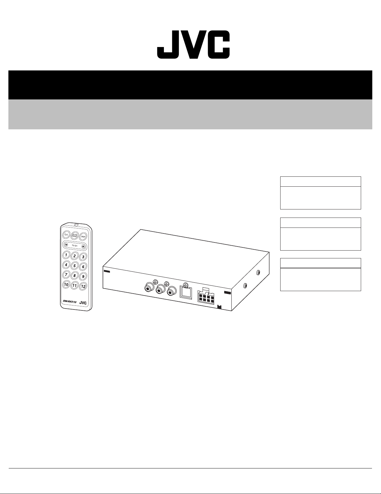
SERVICE MANUAL
TV TUNER UNIT
MA102200411
KV-C1000,KV-C1001,KV-C1008
KV-C1000
Area suffix
J ------------- Northern America
KV-C1001
Area suffix
E ---------- Continental Europe
KV-C1008
Area suffix
A ------------------------- Australia
TABLE OF CONTENTS
1 PRECAUTIONS . . . . . . . . . . . . . . . . . . . . . . . . . . . . . . . . . . . . . . . . . . . . . . . . . . . . . . . . . . . . . . . . . . . . . . . 1-4
2 SPECIFIC SERVICE INSTRUCTIONS . . . . . . . . . . . . . . . . . . . . . . . . . . . . . . . . . . . . . . . . . . . . . . . . . . . . . . 1-6
3 DISASSEMBLY . . . . . . . . . . . . . . . . . . . . . . . . . . . . . . . . . . . . . . . . . . . . . . . . . . . . . . . . . . . . . . . . . . . . . . . 1-7
4 ADJUSTMENT . . . . . . . . . . . . . . . . . . . . . . . . . . . . . . . . . . . . . . . . . . . . . . . . . . . . . . . . . . . . . . . . . . . . . . . . 1-8
5 TROUBLESHOOTING . . . . . . . . . . . . . . . . . . . . . . . . . . . . . . . . . . . . . . . . . . . . . . . . . . . . . . . . . . . . . . . . . 1-14
COPYRIGHT © 2004 Victor Company of Japan, Limited
No.MA102
2004/11
Page 2

SPECIFICATION
KV-C1000
TV TUNER UNIT TV antenna jack × 4
AV bus terminal × 1
Remote sensor jack × 1
Output Video RCA pin × 1; 1 V(p-p), 75 Ω
Audio RCA pin × 2; 150 mV(rms)
Dimensions (W × H × D) 163 mm × 28 mm × 122 mm (6- 7/16 in. × 1- 1/8 in. × 4- 13/16 in.)
Mass 0.6 kg (1.4 lbs)
DIVERSITY ANTENNANA Output impedance 75 Ω × 4 (with mini plug)
Cord length 5 m (16.63 ft)
Dimensions (W × H × D) 440 mm × 490 mm × 18 mm (17- 3/8 in. × 19- 5/16 in. × 3/4 in.) (without
the cable)
Mass (each unit) (approx.) 220 g (0.49 lbs) (including the cable)
GENERAL Channel coverage VHF : ch 2 - 13
UHF : ch 14 - 69
Power requirement Operating voltage : DC 14.4 V (11 V to 16 V allowance)
Grounding system Negative ground
Allowable operating temperature 0ºC to +40ºC (32ºF to 104ºF)
KV-C1001
TV TUNER UNIT TV antenna jack × 4
AV bus terminal × 1
Remote sensor jack × 1
Output Video RCA pin × 1; 1 V(p-p), 75 Ω
Audio RCA pin × 2; 150 mV(rms)
Dimensions (W × H × D) 163 mm × 28 mm × 122 mm
Mass 0.6 kg
DIVERSITY ANTENNANA Output impedance 75 Ω × 4 (with mini plug)
Cord length 5 m
Dimensions (W × H × D) 440 mm × 490 mm × 18 mm (without the cable)
Mass (each unit) (approx.) 220 g (including the cable)
GENERAL Channel coverage CCIR VHF : ch 2 - 12
UHF : ch 21 - 69
Italy VHF : ch A - H2
UHF : ch 21 - 69
Indonesia VHF : ch 1A - 11
UHF : ch 21 - 69
Power requirement Operating voltage : DC 14.4 V (11 V to 16 V allowance)
Grounding system Negative ground
Allowable operating temperature 0ºC to +40ºC
1-2 (No.MA102)
Page 3

KV-C1008
TV TUNER UNIT TV antenna jack × 4
AV bus terminal × 1
Remote sensor jack × 1
Output Video RCA pin × 1; 1 V(p-p), 75 Ω
Audio RCA pin × 2; 150 mV(rms)
Dimensions (W × H × D) 163 mm × 28 mm × 122 mm
Mass 0.6 kg
DIVERSITY ANTENNANA Output impedance 75 Ω × 4 (with mini plug)
Cord length 5 m
Dimensions (W × H × D) 440 mm × 490 mm × 18 mm (without the cable)
Mass (each unit) (approx.) 220 g (including the cable)
GENERAL Channel coverage Australia VHF : ch 0 - 12
UHF : ch 28 - 69
New
Zealand
Indonesia VHF : ch 1A - 11
CCIR VHF : ch 2 - 12
Power requirement Operating voltage : DC 14.4 V (11 V to 16 V allowance)
Grounding system Negative ground
Allowable operating temperature 0ºC to +40ºC
Design and specifications subject to change without notice.
VHF : ch 1 - 11
UHF : ch 21 - 69
UHF : ch 21 - 69
UHF : ch 21 - 69
(No.MA102)1-3
Page 4
1.1 Safety Precautions
SECTION 1
PRECAUTIONS
!
!
Burrs formed during molding may be left over on some parts of the chassis. Therefore,
pay attention to such burrs in the case of preforming repair of this system.
Please use enough caution not to see the beam directly or touch it in case of an
adjustment or operation check.
1-4 (No.MA102)
Page 5

1.2 Important for laser products
!
1.CLASS 1 LASER PRODUCT
2.DANGER : Invisible laser radiation when open and inter
lock failed or defeated. Avoid direct exposure to beam.
3.CAUTION : There are no serviceable parts inside the
Laser Unit. Do not disassemble the Laser Unit. Replace
the complete Laser Unit if it malfunctions.
4.CAUTION : The CD,MD and DVD player uses invisible
laser radiation and is equipped with safety switches which
prevent emission of radiation when the drawer is open and
the safety interlocks have failed or are defeated. It is
dangerous to defeat the safety switches.
5.CAUTION : If safety switches malfunction, the laser is able
to function.
6.CAUTION : Use of controls, adjustments or performance of
procedures other than those specified here in may result in
hazardous radiation exposure.
Please use enough caution not to
see the beam directly or touch it
in case of an adjustment or operation
check.
REPRODUCTION AND POSITION OF LABELS
WARNING LABEL
CAUTION : Visible and Invisible
CLASS 1
LASER PRODUCT
laser radiation when open and
interlock failed or defeated.
AVOID DIRECT EXPOSURE TO
BEAM. (e)
ADVARSEL : Synlig og usynlig
laserstråling når maskinen er
åben eller interlocken fejeler.
Undgå direkte eksponering til
stråling. (d)
VARNING : Synlig och
osynling laserstrålning när
den öppnas och spärren är
urkopplad. Betrakta ej
strålen. (s)
VARO : Avattaessa ja suojalukitus
ohitettuna tai viallisena olet alttiina
näkyvälle ja näkymättömälle
lasersäteilylle. Vältä säteen
kohdistumista suoraan itseesi. (f)
(No.MA102)1-5
Page 6

SECTION 2
SPECIFIC SERVICE INSTRUCTIONS
This service manual does not describe SPECIFIC SERVICE INSTRUCTIONS.
1-6 (No.MA102)
Page 7

SECTION 3
DISASSEMBLY
3.1 Removing the top cover (see fig.1)
(1) Removing the 5 screws A attaching the top cover.
3.2 Removing the tuner board (see fig.2 and 3)
(1) Removing the 2 screws B attaching the AV output jack.
(fig.2)
(2) Removing the one screw C attaching the bus connector.
(fig.2)
(3) Removing the two screws D attaching the tuner board.
(fig.3)
AAA
Fig.1
BC
C
Fig.2
C
TUNER BOARD
Fig.3
(No.MA102)1-7
Page 8

4.1 Test instruments
(1) DC power supply
(2) Multitest signal generator
(3) Attenuator
(4) Wave form monitor
(5) TV monitor
(6) Frequency counter
4.2 Test wiring diagram
DC
POWER
SUPPLY
SECTION 4
ADJUSTMENT
OSCILLOSCOPE
FOR
AUDIO SIGNAL
CHECK
AC MILLIVOLT
METER
(7) Oscilloscope
(Useing audio out confirmation and adjustment)
(8) AC millivolt meter
(9) Distortion meter
(10) Digital multimeter
(voltage adjustment use)
TV
MONITOR
IN
OUT
WAVE FORM
MONITOR
IN
OUT
75 ohm
REMOCON
SENSOR
REMOCON
AUDIO OUT VIDEO
OUT
TV TUNER UNIT
ANT
ATTENUATOR
RF
MULTI TEST SIGNAL
GENERATOR
1-8 (No.MA102)
Page 9

4.3 Adjustment points
C822
TP808
L821
C809
IC801
R447 C443
TP803
R446
R450
R449
R448
R414
R410
IC441
R411
C832
R452
R412
IC831
R814
R815
R816
R443
R442
TP432
R451
C405
CN821
C833
D822
C442
TP424
R813
C831
C806
R425
R419
R424
TP342
R420
R407
TP438
R415
R422
R416
R421
C801
R423
R413
D821
Q812
R409
C805
C803
J471
Q811
R811
Q401
IC401
R417
R408
C821
R812
TP436
D401
C471
TP801
F471
R652
R653
R418
C472
C655
C403
R472
CN471
TP413
C662
R402
L401
R612
Q651
Q803
R401
TP427
S821
C808
R404
TP435
C401
C672
C606
C666
C604
C432
TP437
X401
R680
R431
R602
C670
Q161
D161
R114
C665
C431
Q163
Q162
D162
D163
R116
R115
CN401
IC431
Q164
R165
Q165
R117
L602
C610
R616
R610
R608
C656
IC661
L601
R601
C601
TP264
TP266
TP254
J621
Q151
Q152
C125
R675
C677
R463
R679
C671
R109
R462
C636
C124
R110
TP102
C661
C628
Q154
R112
R101
TP101
R611
R642
R632
C603
C605
Q153
C638
R622
R638
R634
C221
C101
R624
R609
R607
R603
C634
R636
C632
R626
IC602
R605
IC622
TP621
C626
X501
C514
C151
IC101
R103
VR101
Q622
IC601
C112
C640
L503
R512
C113
TP103
R104
C501
IC501
R511
IC621
C507
C121
R505
R506
R513
R502
Q621
C651
C114
R645
C107
R623
R625
C625
C108
C516
IC101
R108
R107
R106
R105
C109
C633
R635
C631
R631
C509
R161
C110
C637
R621
R637
R633
C635
C627
L622
R504
R503
R162
C106
C105
C104
C103
L623
C313
L621
R331
IC301
C322
R313
R312
R332
R507
R163
C314
C508
C251
Q503
R510
R311
D503
R164
C307
R306
C252
C321
C502
C511
C515
R308
R307
C306
R303
R302
R301
C302
C301
C248
J131
C222
TP258
VR222 VR221 L224
C235
L224
VR222
VR221
R244
C223
D232
C246
R233
R305
L221
CF222
C241
VR301
C254
VR223
J132
C236
C249
X221
SF211
IC221
IC221
R239
J133
J134
D231
IC161
R137
R230
C229
TP268
C227
R221
R241
R242
SF212
R232
R222
R138
R231
Q132
Q131
C135
C230
L222
R134
R132
R229
Q231
CF221
L222
VR223
C247
C253
TU201
C163
C202
TP142
4.4 Test points (forward side of P.C.B)
TP225
TP251
C241
TP222
C310
VR222
VR221
VR101
TP224
IC221
TP223
Target voltage 5.4V
IC101
Pin7=TP104
When adjusting step 8
(DIVER frequency adjustment)
connect an additional wire
from pin 8 to GND.
(No.MA102)1-9
Page 10

4.5 SSG Memory
Model No. C1000J
Memory
No.
20 NTSC MULTI BURST OFF ALL ON OFF ----- --------- --- --- ALL OFF
21 NTSC COLOR BAR-2 OFF ALL ON OFF ----- --------- --- --- ALL OFF
25 NTSC COLOR BAR-2 OFF ALL ON OFF ----- --------- --- --- ALL OFF
Color
Video Sound MPX
Signal
select
Multiplex
pattern
Mode
select
Carrier Country
Mode
select
CH1 CH2 Teletext
Memory
No.
20 187.25MHz M N INT 400Hz STD OFF STD INT OFF STD MAX
21 187.25MHz M N INT 400Hz STD OFF STD INT OFF STD MAX
25 187.25MHz M N ---------
* 1: The frequency value is selected at 9 ch .
* 2: Out level is 100 dB µ ± 1 dB when volume to max.
Frequency(MHz)
/PDC VPS
*1
system
TV
RF
fs 1
INT OSC
Video
out put
STD OFF STD INT OFF STD MAX
Carrier out put
Vision Sound
Level
* 1
Model No. C1001E
Video Sound MPX
Memory
No.
30 PAL MULTI BURST OFF ALL ON OFF ----- --------- --- --- ALL OFF
31 PAL COLOR BAR-3 OFF ALL ON OFF ----- --------- --- --- ALL OFF
35 PAL COLOR BAR-3 OFF ALL ON OFF ----- --------- --- --- ALL OFF
Memory
No.
30 203.25MHz B G H INT 400Hz STD OFF STD INT OFF STD MAX
31 203.25MHz B G H INT 400Hz STD OFF STD INT OFF STD MAX
35 203.25MHz B G H --------- STD OFF STD INT OFF STD MAX
* 1: The frequency value is selected at 9 ch .
* 2: Out level is 100 dB µ ± 1 dB when volume to max.
Color
Frequency(MHz)
/PDC VPS
*1
Signal
select
TV
system
Multiplex
pattern
RF
fs 1
INT OSC
Mode
select
Video
out put
Carrier Country
Carrier out put
Vision Sound
Mode
select
CH1 CH2 Teletext
Level
* 1
Other
---------
---------
---------
Other
---------
---------
---------
Model No. C1008A
Video Sound MPX
Memory
No.
40 PAL MULTI BURST OFF ALL ON OFF ----- --------- --- --- ALL OFF
41 PAL COLOR BAR-3 OFF ALL ON OFF ----- --------- --- --- ALL OFF
45 PAL COLOR BAR-3 OFF ALL ON OFF ----- --------- --- --- ALL OFF
Memory
No.
40 196.25MHz B G H INT 400Hz STD OFF STD INT OFF STD MAX
41 196.25MHz B G H INT 400Hz STD OFF STD INT OFF STD MAX
45 196.25MHz B G H --------- STD OFF STD INT OFF STD MAX
* 1: The frequency value is selected at 9 ch .
* 2: Out level is 100 dB µ ± 1 dB when volume to max.
1-10 (No.MA102)
Color
Frequency(MHz)
/PDC VPS
*1
Signal
select
TV
system
Multiplex
pattern
RF
INT OSC
fs 1
Mode
select
Video
out put
Carrier Country
Carrier out put
Vision Sound
Mode
select
CH1 CH2 Teletext
Level
* 1
Other
---------
---------
---------
Page 11

4.6 Adjustment and check method
(1) Turn ON the main power switch.
(2) Serect 9ch from the remote controller.
Step
No.
1
(Preadjustment)
2
(Preadjustment)
S-METER DC
3
(Preadjustment)
4
(Preadjustment)
5
6
7
8
SSG
Item
memory
JEA
RF AGC
adjustment
21 31 41 0dB
V-DETRCT
adjustment 20 30 40
OFFSET
adjustment
21 31 41
SOFT MUTE
adjustment
S-DETECT
adjustment
SOFT MUTE
adjustment
21 31 41
25 35 45
21 31 41
S-METER
sensitivity
21 31 41
adjustment
DIVER
frequency
21 31 41
adjustment
ATT
position
20dB
20dB
20dB
20dB
20dB
20dB
20dB
Measuring instrument
&
check point
Wave form monitor
VIDEO OUT
(TP624)
Wave form monitor
VIDEO OUT
(TP624)
Digital multimeter
(TP225) or
(VR222
-forward side)
Digital multimeter
(TP224) or
(VR221
-forward side)
Digital multimeter
(TP222) or
(C301
-forward side)
AC millivolt meter
AUDIO OUT
(TP622,TP623)
Digital multimeter
(TP223) or
(IC221 pin 12
-forward side)
Frequency counter
(TP104) or
(IC101 pin 7
-forward side)
Adjustment
point
VR223
L222
adjustment value
&
check value
Adjustment of wave form
See Fig.1 and 2
Adjustment of wave form
See Fig.3 and 4
VR222 More then 2.2V
VR221 More then 4.0V
L224 2.5V±0.1V
Confirm wave form
VR221
and adjust until make
mute by the VR221
clockwise rotation.
VR222
VR101
4.1V±0.1V(TP223)
5.4V±0.1V(IC221pin12)
NTSC=15.734KHz
PAL=15.625KHz
Notes
Note
1
Wave form monitor
VIDEO OUT
(TP624)
TV monitor
VIDEO OUT
(TP624)
Oscilloscope
(TP251) or
(C241
-forward side)
Oscilloscope
(TP251) or
(C241
-forward side)
9
10
11
12
RF AGC
adjustment
RF AGC
check
SD DETECT
LEVEL
check (H)
SD DETECT
LEVEL
check (L)
21 31 41
21 31 41
21 31 41
21 31 41
0dB
70dB
70dB
90dB
VIDEO
13
FREQUENCY
RESPONSE
20 30 40
20dB
Wave form monitor
VIDEO OUT(TP624)
check
Note 1: KV-C1000=NTSC , KV-C1001=PAL , KV-C1008=PAL
VR223
-----
Adjustment of wave form
See Fig.1 and 2
Confirm the
slightly output wave form
----- H (5.0V)
-----
L (0.0v)
NTSC=0.5MHz : 3.58MHz
-----
PAL=0.5MHz : 4.00MHz
less then 10dB
Note
1
(No.MA102)1-11
Page 12

Step
No.
FREQUENCY
14
check(AV BUS)
15
16
Item
VIDEO
RESPONSE
VIDEO
LEVEL
check
(AV OUT)
AUDIO
OUTPUT
LEVEL
check
(AV OUT)
SSG
memory
JEA
20 30 40
21 31 41
21 31 41
ATT
position
20dB
20dB
20dB
Measuring instrument
&
check point
Wave form monitor
VIDEO OUT(TP471)
Wave form monitor
VIDEO OUT(TP624)
AC millivolt meter
AUDIO OUT
(TP622,TP623)
Adjustment
point
-----
-----
-----
adjustment value
&
check value
NTSC=0.5MHz : 3.58MHz
PAL=0.5MHz : 4.00MHz
less then 10dB
More then 90 IRE
More then 30 IRE
235 to 380 mV
( 60 % MOD.)
Notes
Note
1
Note
2
DISTORTION
17
(AV OUT)
VIDEO LEVEL
18
(AV BUS)
AUDIO OUTPUT
19
LEVEL
check(AN BUS)
DISTORTION
20
(AV BUS)
check
check
check
21 31 41
21 31 41
21 31 41
21 31 41
20dB
20dB
20dB
20dB
Distortion meter
AUDIO OUT ----- Less then 2.5%
(TP622,TP623)
Wave form monitor
VIDEO OUT(TP471)
AC millivolt meter
AUDIO OUT
(TP474,TP45)
Distortion meter
AUDIO OUT
(TP474,TP475)
Note 1: KV-C1000=NTSC , KV-C1001=PAL , KV-C1008=PAL
Note 2 : VIDEO : More then 90 IRE ,SYNC : More then 30 IRE
-----
-----
More then 90 IRE
More then 30 IRE
235 to 380 mV
( 30 % MOD.)
----- Less then 2.5%
Note
2
1-12 (No.MA102)
Page 13

4.7 Waveforms
Check point 1
RFAGC adjust (NTSC) Fig. 1
Check point 2
VDETECT adjust (NTSC) Fig. 3
Check point 1
RFAGC adjust (PAL) Fig. 2
Check point 2
V-DETECT adjust (PAL) Fig. 4
Check point 1 : The whole waveform should be looking sharp.
The check point 1 waveform adjustment is the lower position.
Check point 2 : The whole waveform should be looking sharp.
The check point 2 waveform amplitude adjustment is the smaller and lower position.
(No.MA102)1-13
Page 14

5.1 Power cord for TV tuner
SECTION 5
TROUBLESHOOTING
5 RD
6 NC
BL/WH
7
8 YL
1 NC
2 NC
3 NC
4 BK
4 BK
5 RD
7 BL/WH
8 YL
BK
BL
WH
Black
Blue
White
2000 mm
RD
YL
3A
Fuse 250V-3A
Red
Yellow
GROUND
POWER
LEAD
REMOTE
OUT
POWER LEAD/
MEMORY BACK UP
1-14 (No.MA102)
Page 15

5.2 AV bus cable between Hideaway unit and TV tuner unit
10
6
4
12
11
7
5
1
3000 mm
1
2
3
4
5
6
GND
NC
TV-VGND
TV-V
SCK
NC
Black
Gray
Black(Tube)
Natural
White
Pink
7
8
9
10
11
12
MEMORY
REMOTE
TV-S.GND
TV-L
SI/SO
TV-R
Red
Brown
Black(Tube)
Purple
Yellow
Blue
(No.MA102)1-15
Page 16

Victor Company of Japan, Limited
AV & MULTIMEDIA COMPANY CAR ELECTRONICS CATEGORY 10-1,1chome,Ohwatari-machi,Maebashi-city,371-8543,Japan
(No.MA102)
Printed in Japan
VPT
 Loading...