

Page 1
KV-C1000
TV Tuner Unit : Instructions
Unidad de sintonizador de TV : Manual de instrucciones
LVT1183-001A
INFORMATION (For U.S.A. only)
This equipment has been tested and found to comply with the limits for a Class B digital device,
pursuant to Part 15 of the FCC Rules. These limits are designed to provide reasonable protection
against harmful interference in a residential installation. This equipment generates, uses, and can
radiate radio frequency energy and, if not installed and used in accordance with the instructions,
may cause harmful interference to radio communications. However, there is no guarantee that
interference will not occur in a particular installation. If this equipment does cause harmful interference
to radio or television reception, which can be determined by turning the equipment off and on, the
user is encouraged to try to correct the interference by one or more of the following measures:
Appareil de tuner de télévision : Manuel d’instructions
[J]
電視調諧器:使用說明書
For customer Use:
Enter below the Model No. and Serial No. which are located on the top or
bottom of the cabinet. Retain this information for future reference.
Model No.
Serial No.
© 2004 Victor Company of Japan, Limited
– Reorient or relocate the receiving antenna.
– Increase the separation between the equipment and receiver.
– Connect the equipment into an outlet on a circuit different from that to which the receiver is
connected.
– Consult the dealer or an experienced radio/TV technician for help.
0904MNMMDWJEIN
EN, SP, FR, CT
WARNINGS
• USE WITH DC 12 V NEGATIVE GROUND
VEHICLES.
If your vehicle does not have this system, a
voltage inverter is required, which can be
purchased at JVC car audio dealers.
• DO NOT INSTALL THE MONITOR IN A
LOCATION WHICH OBSTRUCTS DRIVING
AND VISIBILITY, OR WHERE APPLICABLE
LAWS AND REGULATIONS PROHIBIT THE
INSTALLATION.
• NEVER USE BOLTS OR NUTS FROM THE
VEHICLE’S SAFETY DEVICES FOR
INSTALLATION.
If bolts or nuts from the steering wheel, brakes
or other safety devices are used for
installation, it may cause an accident.
• INSTALL THE ANTENNA IN A PROPER
LOCATION.
Be sure to select a location for installation of
the antenna so that the antenna is not protruding
beyond the width or the front or back of the
vehicle. If it is protruding, it might come into
contact with a pedestrian or other object and
cause an accident.
• ATTACH THE WIRES CORRECTLY.
If the wiring is not correctly performed, it may
cause a fire or an accident. In particular, be
sure to run and secure the lead wire so that it
does not get tangled with a screw or the
moving portion of a seat rail.
To prevent short circuits, it is recommended
that you disconnect the battery’s negative
terminal and make all electrical connections
before installing the unit. If you are not sure
how to install this unit correctly, have it
installed by a qualified technician.
• Avoid installing the unit in the following
places.
– Where it would hinder your safety driving.
– Where it would be exposed to direct sunlight
or heat directly from the heater or placed in
an extremely hot place.
– Where it would be subject to rain, water
splashes or excessive humidity.
– Where it would be subject to dust.
– Where it would be positioned on an unstable
place.
– Where it could damage the car’s fittings.
– Where proper ventilation would not be
maintained, such as under a floor mat.
– Where it would be located near inflammable
objects (since heat is generated inside the
unit).
• Handle the Lithium coin battery (product
number: CR2025) with care.
– Store the battery in a place where children
cannot reach.
If a child accidentally swallows the battery,
consult a doctor immediately.
– Do not recharge, short, disassemble, or heat
the battery or dispose of it in a fire.
These behaviors may cause the battery to
be overheated, crack or fire.
– Do not leave the battery with other metallic
materials.
Doing this may cause the battery to be
overheated or cracked. It may cause a fire.
– When throwing away or saving the battery,
wrap it in tape and insulate; otherwise, the
battery may be overheated, crack or fire.
– Do not poke the battery with tweezers or
similar tools.
Doing this may cause the battery to be
overheated or cracked. It may cause a fire.
ADVERTENCIA
• PARA USAR EN VEHÍCULOS DE 12 V CC
CON NEGATIVO A MASA.
Si su vehículo no posee este sistema, será
necesario un inversor de tensión, que puede
ser adquirido en los concesionarios de JVC
de equipos de audio para automóviles.
• NO INSTALE EL MONITOR EN LUGARES
QUE IMPIDAN EL MANEJO O LA
VISIBILIDAD, NI DONDE LOS PROHÍBAN
LAS LEYES Y LOS REGLAMENTOS
APLICABLES.
NUNCA UTILICE PERNOS O TUERCAS DE
•
LOS DISPOSITIVOS DE SEGURIDAD DEL
VEHÍCULO PARA HACER LA INSTALACIÓN.
Si se utilizaran los pernos o tuercas del
volante, frenos, u otros dispositivos de
seguridad para hacer la instalación, se podrá
producir un accidente.
• INSTALE LA ANTENA EN EL LUGAR
APROPIADO.
Asegúrese de seleccionar un lugar de
instalación para la antena donde ésta no
sobresalga más allá de la anchura delantera
o trasera del vehículo. Si sobresale la antena,
ésta podrá entrar en contacto con peatones
u otros objetos y causar un accidente.
• REALICE CORRECTAMENTE EL CABLEADO.
Si el cableado no está correctamente
instalado, podría producirse un incendio o un
accidente. Especialmente, asegúrese de
tender y fijar el cable conductor de manera
que no quede enredado en un tornillo o en la
parte móvil del riel del asiento.
Para evitar cortocircuitos, se recomienda
desconectar el terminal negativo de la
batería y realizar todas las conexiones
eléctricas antes de instalar la unidad. Si no
está seguro de poder instalar la unidad
correctamente, déjela en manos de un
técnico cualificado.
• Evite instalar la unidad en los siguientes
lugares:
– Donde pueda constituir un obstáculo para
la conducción.
– Donde pueda quedar expuesto a la luz
solar directa o al calor directo de un
calefactor, o en un lugar muy caliente.
– Donde pueda mojarse debido a la lluvia,
las salpicaduras de agua o la humedad
excesiva.
– En un lugar polvoriento.
– En un sitio inestable.
– Donde pueda producir daños en los
herrajes del automóvil.
– En lugares donde no pueda obtenerse una
ventilación adecuada, como debajo de la
alfombra del piso.
– En un lugar situado cerca de objetos
inflamables (debido a que se genera calor
dentro de la unidad).
• Maneje la pila botón de litio (número del
producto: CR2025) con cuidado.
Guarde la pila fuera del alcance de los niños.
–
Si un niño llegara a ingerir la pila
accidentalmente, acuda inmediatamente al
médico.
– No debe recargar, cortocircuitar, desarmar,
calentar, ni arrojar la pila al fuego.
Tales acciones podrían hacer que la pila se
recaliente, se agriete o que provoque un
incendio.
– No deje la pila con otros objetos de metal.
De hacerlo, podría recalentarse, agrietarse
o provocar un incendio.
– Cuando tenga que desechar o guardar la
pila, aíslela enrollando una cinta; de lo
contrario, podría recalentarse, agrietarse o
provocar un incendio.
– No toque la pila con pinzas u otras
herramientas similares. De hacerlo, podría
recalentarse, agrietarse o provocar un
incendio.
FRANÇAISESPAÑOLENGLISH
AVERTISSEMENT
•
UTILISATION SUR LES VEHICULES DE 12 V
CC À MASSE NÉGATIVE.
Si votre véhicule n’offre pas ce type
d’alimentation, il vous faut un convertisseur
de tension, que vous pouvez acheter chez un
revendeur d’autoradios JVC.
• N’INSTALLEZ PAS LE MONITEUR DANS
UN ENDROIT QUI GÈNE LA CONDUITE ET
LA VISIBILITÉ, OU DANS UN ENDROIT
INTERDIT PAR LE CODE DE LA ROUTE ET
LA LOI.
• N’UTILISEZ JAMAIS POUR
L’INSTALLATION DES BOULONS OU DES
ÉCROUS PROVENANT DES DISPOSITIFS
DE SÉCURITÉ DU VEHICULE.
Si vous utilisez pour l’installation des boulons
et des écrous du volant, des freins ou d’autres
dispositifs de sécurités, cela risquerait de
provoquer des accidents.
• INSTALLEZ L’ANTENNE DANS UN
EMPLACEMENT ADEQUAT.
Choisissez correctement l’emplacement
d’installation de l’antenne de sorte qu’elle ne
dépasse pas par les côtés, l’avant ou l’arrière
du véhicule. Si l’antenne dépasse, elle peut
heurter un piéton, ou un objet quelconque et
risquer de causer un accident.
• ATTACHER LES FILS CORRECTEMENT.
Si le câblage n’est pas réalisé correctement,
cela risque de provoquer un incendie ou autre
accident. Assurez-vous, en particulier, de tirer
et d’attacher les fils de sorte qu’ils ne
s’accrochent pas à une vis ni ne se coincent
dans les parties mobiles des rails des sièges.
Pour éviter les courts-circuits,
recommandons que vous déconnectiez la
borne négative de la batterie et réalisiez
toutes les connexions électriques avant
d’installer l’appareil. Si vous n’êtes pas sûr de
savoir comment installer cet appareil
correctement, faites-le installer par un
technicien qualifié.
• Évitez d’installer l’appareil dans les
endroits suivants.
– Où il peut gêner la conduite de la voiture.
– Où il est exposé à la lumière directe du
soleil, à la chaleur directe du chauffage ou
placé dans un endroit très chaud.
– Où il est sujet à la pluie, aux éclaboussures
ou à une humidité excessive.
– Où il est sujet à la poussière.
Où il est positionné dans un endroit instable.
–
– Où il peut endommager les accessoires de
la voiture.
– Où une ventilation correcte ne peut pas être
obtenue, comme sous un tapis de sol.
Près d’objets inflammables (car de la chaleur
–
est produite à l’intérieur de l’appareil).
• Manipulez de la pile-bouton au Lithium
(produit numéro: CR2025) avec
précaution.
– Conservez la pile dans un endroit hors de la
portée des enfants.
Si un enfant avalait accidentellement la pile,
consultez un médecin immédiatement.
– Ne recherchez pas, ne court-circuitez pas,
ne démontez pas ni ne chauffez la pile et ne
la jetez pas dans le feu.
Cela pourrait entraîner une surchauffe de la
pile, un éclatement ou un incendie.
– Ne laissez pas la pile avec d’autres objets
métalliques.
Cela pourrait entraîner une surchauffe de la
pile, un éclatement ou un incendie.
– Pour vous débarrasser de la pile ou la
conserver, enveloppez-la de ruban adhésif
et isolez-la, sinon cela pourrait entraîner
une surchauffe de la pile, un éclatement ou
un incendie.
– Ne piquez pas la pile avec des pinces ou un
outil similaire.
Cela pourrait entraîner une surchauffe de la
pile, un éclatement ou un incendie.
1
nous
中文
警告
• 与直流 12 V,負極接地的車輛使用。
如果您的車輛沒有這一電源系統,則需要一
個電壓變換器,可以在 JVC 汽車音響分銷商
處買到。
• 切勿將監控器安裝在妨礙駕駛和可見性的位置
或者有相應法律和規則禁止該安裝的地方。
• 切勿將車輛安全裝置的螺栓或螺旋帽用於安
裝。
如果將方向盤,煞車或其他安全裝置的螺栓
或螺旋帽用於安裝,有可能造成意外。
• 將天線安裝在恰當的位置。
確保選擇一個安裝天線的地方,使天線不會
伸出車輛的寬度,前部或後部。如果伸出,
有可能碰到行人或其他物體而造成意外。
• 正確安裝電線。
如果電線連接出錯,可能會導致火災或意
外。特別要確保連接好主線,才不會跟螺絲
或座椅導軌的的移動部份纏在一起。
為了防止短路,建議在安裝本機之前斷開電
池的負極端子并進行所有電路連接。如果您
沒把握正確地安裝本機,請委托專業的技術
人員為您安裝。
• 避免將本機安裝在下列地方。
–
防礙您安全駕駛的地方。
–
暴露於陽光直射或直接對着暖气的地方,或
放置在極端炎熱的地方。
–
被雨淋,水濺或極端潮濕的地方。
–
會沾到灰塵的地方。
–
被放置在不平穩的地方。
–
會損傷汽車配件的地方。
–
不能保持正常通風的地方,如地墊下。
–
被放置在易燃物附近(因為本機內部產生熱
氣)。
• 小心握持硬幣形鋰電池(產品型號:
CR2025)。
–
將電池放在孩童無法拿到的地方。
如果孩童不慎吞咽了電池,請馬上就醫。
–
切勿為電池充電,使電池短路,分解電池,
加熱電池或者遺棄在火中。
上述任何行為都可能導致電池過熱,炸裂或
引起火災。
–
切勿將電池与其他金屬物質放在一起。
如此行為可能導致電池過熱或者炸裂。這可
能會引起火災。
–
要廢棄或保存電池時,請用膠帶纏繞并使其
處於絕緣狀態;否則可能導致電池過熱,炸
裂或引起火災。
–
切勿以鑷子或類似的工具穿刺電池。
如此行為可能導致電池過熱或者炸裂。這可
能會引起火災。
Page 2
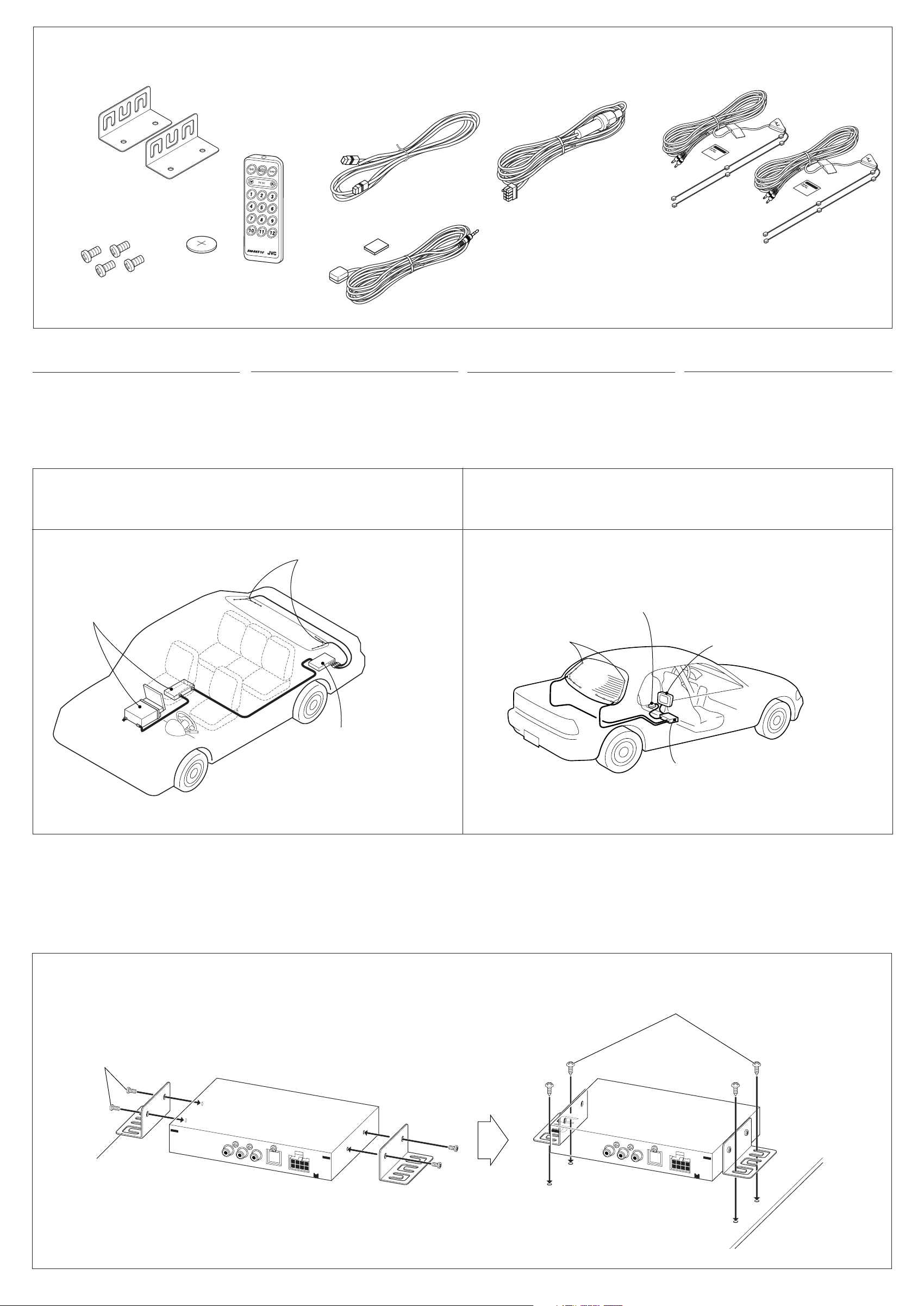
Parts list
The following parts are provided with this unit.
After checking them, please set them correctly.
Brackets
Ménsulas
Supports
托座
Lista de piezas
Con esta unidad se suministran las siguientes
piezas.
Después de inspeccionarlas, colóquelas
correctamente.
Remote controller
Control remoto
Télécommande
遙控器
AV bus cable
Cable AV bus
Câble de liaison AV
AV 巴士電纜
Liste des pièces
Les pièces suivantes sont fournies avec cet
appareil.
Après vérification, veuillez les installer
correctement.
零件清單
下列零件是隨本機提供的。
清點以後,請正確地將其裝配。
3
Fixing screws—M4 x 8 mm (M4 x
Tornillos de fijación—M4 x 8 mm
Vis de fixation—M4 x 8 mm
固定螺絲—M4 x 8 mm
INSTALLATION
• The following illustrations show typical
installation.
If you have any questions or require
information regarding installation kits, consult
your JVC car audio dealer or a company
supplying kits.
/8 in.)
CR2025
Battery
Pila
Pile
電池
RM-RK510
INSTALACION
• La siguiente ilustración muestra una
instalación típica.
Si tiene alguna pregunta o necesita
información acerca de los kits de instalación,
consulte con su concesionario de JVC de
equipos de audio para automóviles o con
una compañía que suministra tales kits.
When used with KD-AV7000/KD-AV7005:
Cuando se utiliza con el KD-AV7000/KD-AV7005:
Utilisation avec le KD-AV7000/KD-AV7005:
与 KD-AV7000/KD-AV7005 一起使用時:
Power cord
Cordón de alimentación
Cordon d’alimentation
電源線
Remote sensor unit with double-faced adhesive tape
Unidad sensora remota con cinta adhesiva de doble cara
Capteur de télécommande avec ruban adhésif à double face
附帶雙面粘貼膠帶的遙感窗
INSTALLATION
•
L’illustration suivante montre une installation
typique.
Si vous avez des questions ou avez besoin
d’information sur des kits d’installation,
consulter votre revendeur d’autoradios JVC ou
une société fournissant de tels kits.
When used with another monitor system:
Cuando se utiliza con otro sistema de monitor:
Utilisation avec un autre système de moniteur:
与另一個監控系統一起使用時:
Diversity antennas with a cleaner
Antenas de diversidad con limpiador
Antenne de réception en diversité avec papier
nettoyant
附帶吸塵器的智慧型天線
安裝
• 下面的圖解表示了典型的安裝程序。
如果您有問題,或需要有關配套元件的資
料,請向 JVC 汽車音響經銷商或配套元件供
應公司詢問。
KD-AV7000/KD-AV7005 (separately purchased)
KD-AV7000/KD-AV7005 (vendido separadamente)
KD-AV7000/KD-AV7005 (à acheter séparément)
KD-AV7000/KD-AV7005 (另購)
Diversity antenna
Antena de diversidad
Antenne de réception en diversité
智慧型天線
TV tuner unit (in trunk)
Unidad de sintonizador de TV (en el baúl)
Appareil de tuner de télévision (dans le coffre)
電視調諧器(行李箱上)
Diversity antenna
Antena de diversidad
Antenne de réception en diversité
智慧型天線
Remote sensor unit
Unidad sensora remota
Capteur de télécommande
遙感窗
Monitor system (separately purchased)
Sistema de monitor (vendido separadamente)
Système de moniteur (à acheter séparément)
監控系統(另購)
TV tuner unit (under the passenger’s seat)
Unidad de sintonizador de TV (debajo del asiento del pasajero)
Appareil de tuner de télévision (sous le siège du passager)
電視調諧器(在乘客座位下)
Installing the unit
While mounting the unit, be sure to use the
tapping screws (not supplied) of appropriate
length so that they will not damage any parts of
the car.
Fixing screws—M4 x 8 mm (M4 x 3/8 in.)
Tornillos de fijación—M4 x 8 mm
Vis de fixation—M4 x 8 mm
固定螺絲—M4 x 8 mm
Bracket
Ménsula
Support
托座
Instalación de la unidad
Al instalar la unidad, asegúrese de utilizar
tornillos autorroscantes (no suministrados) del
largo apropiado para que no produzcan daño
alguno a las partes del automóvil.
Instalation de l’appareil
Pour installer
des vis autotaraudeuses (non fournies) d’une
longueur appropriée de façon à n’endommager
aucune partie de la voiture.
l’appareil, assurez-vous d’utiliser
Tapping screws (not supplied)
Tornillos autorroscantes (no suministrados)
Vis autotaraudeuses (non fournies)
自攻螺絲(另購)
Floor
Piso
Plancher
地面
安裝本機
在固定本機時,確保使用適當長度的自攻螺絲
(另購)以便不會損傷汽車的任何部件。
2
Page 3
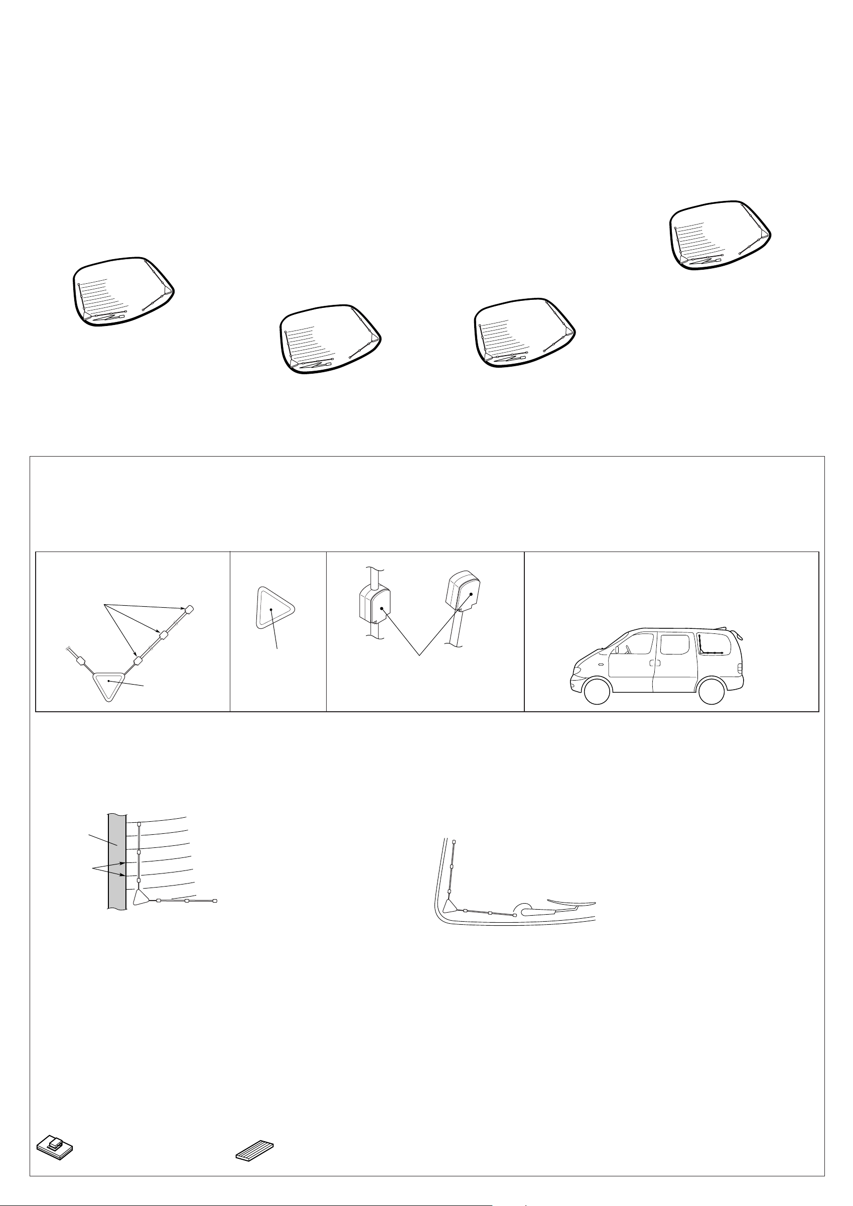
Installing the antenna
Before installing:
• The diversity antenna supplied with this unit is
designed specifically for use with JVC TV
tuner unit. (It cannot be connected to the car
radio.)
• Do not rub the antenna or the antenna’s cable
with alcohol, benzine, thinner, gasoline or
other volatile substances.
• Attach to the inside of the car window glass.
• Be sure to wipe the window surface where the
antenna will be attached with the cleaner
(supplied) to remove moisture, dirt, dust, wax,
oil or other substances. (If there is moisture,
oil or other wet substances on the attachment
surface, the attachment tape will not stick well
and easily come off.)
• Identify the exact attachment location and
confirm that the adhesive surfaces (antenna
base and attachment parts) will not be placed
on a heating wire, glass antenna or wiper
motor.
CAUTION
Since there may be legal regulations defining
the permissible installation locations for the
monitor system which differ by country or by
state, be sure to install the monitor in a location
complying with any such laws.
Instalación de la antena
Antes de hacer la instalación:
• La antena de diversidad suministrada con
esta unidad está diseñada específicamente
para usar con la unidad de sintonizador de
TV de JVC. (No se puede conectar a una
radio para automóvil).
• No frote la antena ni su cable con alcohol,
bencina, diluyente, gasolina u otras
sustancias volátiles.
• Colóquela en el interior de una ventana de
automóvil.
Asegúrese de limpiar la superficie de la ventana
•
donde va a colocarse la antena empleando el
limpiador (suministrado) para quitar la
humedad, la suciedad, el polvo, la cera, el
aceite u otras sustancias. (Si hay humedad,
aceite, u otras sustancias sobre la superficie de
instalación, la cinta de fijación no podrá
adherirse completamente y se desprenderá
fácilmente).
• Identifique exactamente el lugar de
instalación y confirme que las superficies
adhesivas (bases de la antena y partes de
fijación) no queden colocadas sobre los hilos
térmicos, la antena del vidrio o el motor del
limpialunetas.
PRECAUCIÓN
Pueden existir reglamentos locales que definen
los lugares de instalación permisibles para el
sistema de monitor y que difieren según el país
o el estado; por lo tanto, asegúrese de instalar
el sistema de monitor en el lugar correcto, de
conformidad con tales reglamentos.
Installation de l’antenne
Avant l’installation:
• L’antenne de réception en diversité fournie
avec cet appareil est spécialement conçue
pour être utilisé avec un tuner de télévision
JVC. (Elle ne peut pas être connectée à
l’autoradio.)
• Ne frottez pas l’antenne ou le câble d’antenne
avec de l’alcool, de la benzine, du diluant, de
l’essence ou toutes autres substances
volatiles.
• Fixez-la à l’intérieur de la vitre de la voiture.
• N’oubliez pas de frotter la surface de la vitre
où doit être fixée l’antenne avec le nettoyant
(fourni) afin d’enlever l’humidité, les saletés, la
poussière, la cire, les traces de graisse et
toutes autres impuretés. (Si de l’humidité, des
traces de graisse ou d’autres substances
humides subsistent sur la surface de fixation,
les surfaces adhésives n’adhéreront pas
correctement et finiront par se détacher.)
• Repérer exactement l’emplacement de fixation
et vérifiez que les surfaces adhésives (base de
l’antenne et pièces de fixation) ne sont pas
placées sur un fil chauffant, l’antenne de vitre,
ou le moteur d’essuie-glace.
ATTENTION
Il peut exister des réglementations définissant
les emplacements d’installation autorisés pour
un moniteur et celles-ci peuvent varier d’une
région ou d’un pays à l’autre. Assurez-vous
d’installer le moniteur dans un endroit conforme
à ces lois.
安裝天線
安裝之前:
•
隨本機附帶的智慧型天線是特別為 JVC 電視
調諧器設計的。(無法連接至其他汽車音
響。)
•
不要用酒精,石油精,稀釋劑,汽油或其他揮
發性物質擦拭天線或天線電纜。
•
黏貼在汽車玻璃窗內側。
•
確保用清潔布(附帶)擦拭黏貼天線的車窗表
面以擦去濕氣,髒物,灰塵,蠟物,油脂或其
他東西。(如果安裝表面有濕氣,油脂或其他
潮濕的東西,固定的膠帶無法貼好,很容易脫
落。)
•
認準確切的黏貼位置,並確定黏著表面(天線
底座和固定部分)不會放在加熱線,玻璃天線
或雨刮馬達上。
注意
由於可能有關於監控器可安裝位置的法規,並且
因國家或州的不同而异, 確保將監控器安裝在
符合此類法令的地方。
1
Peel off the cover paper from the antenna
base and attach to the surface.
2
Peel off the cover paper from the attachment
parts in turn and attach to the
Attachment parts
Partes de fijación
Pièces de fixation
固定部分
surface.
Antenna base
Base de la antena
Base de l’antenne
天線底座
1
Retire el papel protector de la base de la
antena, y fíjela a la superficie.
2
Retire el papel protector de las partes de
fijación y fíjela a la superficie.
1
Peel off the cover
paper.
Retire el papel protector.
Décollez le papier
protecteur.
除去封面紙。
2
• When the attachment surface overlaps with an electrode
Cuando la superficie de fijación se superpone a un electrodo
Si surface de fixation chevauche une électrode
當黏貼表面與電極重疊時
Electrode
Electrodo
Électrode
電極
Heating wires
Hilos térmicos
Fils chauffants
加熱線
Attach the antenna to either the left or right of the
electrode.
Fije la antena a la izquierda o a la derecha del
electrodo.
Fixez l’antenne soit à gauche, soit à droite de
l’électrode.
將天線黏貼在電極的左邊或右邊。
1
Décollez le papier protecteur du ruban
adhésif de la base de l’antenne et collez
celle dernière sur la surface.
2
Décollez, l’un après l’autre, le papier
protecteur des pièces de fixation et collez
ces dernières sur la surface.
Peel off the cover paper.
Retire el papel protector.
Décollez le papier protecteur.
除去封面紙。
• When the attachment surface interferes with a rear wiper motor or a
high-mounted brake light
Cuando la superficie de fijación interfiera con el motor del
limpialunetas o una luz de parada montada en lo alto
Si la surface de fixation gêne le moteur d’essuie-glace ou un feu de
freinage surélevé
當黏貼表面干撓到後雨刮馬達或高置式煞車燈時
1
除去天線底座的封面紙並固定在表面上。
2
依次除去固定部分的封面紙並固定在表面上。
Attachment location / Lugar de fijación /
Emplacement de fixation / 黏貼位置
Example of installation, side window
Ejemplos de instalación en una ventana lateral
Exemple d’installation sur la vitre latérale
安裝范例,側窗
Move the antenna’s attachment position upwards to
avoid interference.
Mueva la posición de colocación de la antena hacia
arriba para evitar interferencias.
Déplacez la position d’installation de l’antenne vers
le haut jusqu’à ce qu’elle ne gêne plus.
• Installing the antenna cord
Instalación del cable de la antena
Installation du cordon d’antenne
安裝天線電線
Install the cord from the antenna to the TV tuner unit through the interior trim and under the
carpet, and secure it using the cord clampers and mirror mats.
Instale el cable que va de la antena al sintonizador de TV a través del tapizado interior o por
debajo de la alfombra, y asegúrelo utilizando abrazaderas para cable y mats de espejo.
Tirez le cordon de l’antenne à partir du tuner de télévision en le faisant passer par la garniture
intérieure et sous le tapis de sol et fixez-le en utilisant les colliers de cordon et les garnitures
éponges.
通過裝飾用木料和地毯下將電線從天線裝到電視調諧器上,並用電線夾鉗和鏡墊將其固定住。
Cord clampers (separately purchased)
Abrazaderas de cables (vendido
separadamente)
Colliers de cordon (à acheter séparément)
電線夾鉗(另購)
Mirror mats (separately purchased)
Esteras de espejo (vendido separadamente)
Garnitures éponges (à acheter séparément)
鏡墊(另購)
將天線的黏貼位置朝上移以避免干擾。
3
Page 4
ENGLISH
ESPAÑOL
FRANÇAIS
中文
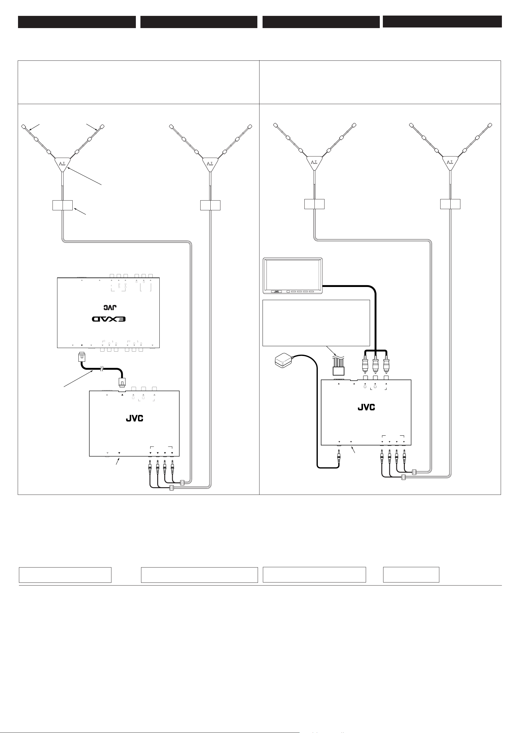
ELECTRICAL CONNECTIONS
CONEXIONES ELECTRICAS
When used with KD-AV7000/KD-AV7005:
Cuando se utiliza con el KD-AV7000/KD-AV7005:
Utilisation avec le KD-AV7000/KD-AV7005:
与 KD-AV7000/KD-AV7005 一起使用時:
Antenna element
Elemento de antena
Élément d’antenne
天線元
Antenna base
Base de la antena
Base de l’antenne
天線底座
CONNEXIONS ELECTRIQUES
電路連接
When used with another monitor system:
Cuando se utiliza con otro sistema de monitor:
Utilisation avec un autre système de moniteur:
与另一個監控系統一起使用時:
Cord protector *1
Protector del cable *1
Protecteur de cordon
*1
電線保護裝置 *1
Hideaway unit (supplied for KD-AV7000/KD-AV7005)
Unidad oculta (suministrada para KD-AV7000/KD-AV7005)
Appareil satellite (fourni avec le KD-AV7000/KD-AV7005)
隱藏器(供 KD-AV7000/KD-AV7005 使用 )
SPEAKER
CENTER
REMOTE
BACKCAMERA
VIDEO TO CHANGER AV BUS TO MAIN UNIT
L
SUB
CENTER
AV INPUT 2
AUDIO
WOOFER
R
R
R
L
L
PRE OUT
MULTIMEDIA DVD/CD RECEIVER WITH REMOVABLE MONITOR HIDEAWAY UNIT
AV INPUT 1
AUDIO
R
L
VIDEO
POWER
AUDIO
FRONT
REAR
AV bus cable
(supplied) *2
Cable AV bus
POWER AV BUS
AUDIO
L
R
AV OUTPUT
(suministrado) *2
Câble de liaison AV
(fourni)
*2
AV 巴士電纜
TV TUNER UNIT KV-C1000
(附帶)*2
REMOTE
RESET
SENSOR
AV OUTPUT
VIDEO
VIDEO L R
FM / AM ANTENNA
TV ANTENNA
3214
Monitor system (separately purchased)
Sistema de monitor (vendido separadamente)
Système de moniteur (à acheter séparément)
監控系統(另購)
See “Typical Connections” on page 5.
Véase “Conexiones típicas” en la página 5.
Voir “Connexions typiques” à la page 5.
參閱第 5 頁的“典型的接線方法”。
Remote sensor unit
Unidad sensora remota
Capteur de télécommande
POWER AV BUS
遙感窗
REMOTE
SENSOR
L
AUDIO
R
AV OUTPUT
TV TUNER UNIT KV-C1000
RESET
*3
VIDEO
TV ANTENNA
3214
*3
*1 Use this to protect the cord (not to be pinched with
the door, etc.)
*2 For controlling KV-C1000 through KD-AV7000/
KD-AV7005, this connection is only required. For
other connections, refer to the manual supplied for
KD-AV7000/KD-AV7005.
*3 Reset the unit after installation is finished by
pressing in with a ball-point pen or a similar
tool.
TROUBLESHOOTING
When used with any other monitor system
than KD-AV7000/KD-AV7005.
• TV tuner does not work at all.
* Is the remote sensor unit connected
correctly?
• No sound is heard.
* Have you adjusted the volume level on the
monitor?
• Picture does not come on the screen.
* Is the correct input selected on the monitor?
• The fuse blows.
* Are the red, yellow, and black leads
connected correctly?
• Power cannot be turned on.
* Is the yellow lead connected?
*1 Utilícelo para proteger el cable (para que el
cable no quede pillado con la puerta, etc.).
*2 Esta conexión es necesaria solamente para
controlar el KV-C1000 a través del KD-AV7000/
KD-AV7005. Para las demás conexiones,
refiérase al manual del KD-AV7000/KD-AV7005.
*3 Tras finalizar la instalación, reinicialice la
unidad utilizando un bolígrafo o un objeto
similar.
LOCALIZACION DE AVERIAS
Cuando se utiliza con cualquier otro sistema
de monitor que no sea KD-AV7000/KD-AV7005.
• El sintonizador de TV no funciona.
* ¿La unidad sensora remota está
correctamente conectada?
• No se escucha sonido.
* ¿Ha ajustado el nivel de volumen en el
monitor?
• La imagen no aparece en la pantalla.
* ¿Se ha seleccionado la entrada correcta en el
monitor?
• El fusible se quema.
* ¿Están los conductores rojo, amarillo y negro
correctamente conectados?
• No es posible conectar la alimentación.
* ¿Está conectado el conductor amarillo?
*1
Pour protéger le cordon (afin qu’il ne se prenne
pas dans la porte, etc.)
*2
Cette connexion est nécessaire pour commander
le KV-C1000 à travers le KD-AV7000/KD-AV7005.
Pour les autres connexions, référez-vous au
manuel fourni avec le KD-AV7000/KD-AV7005.
*3 Réinitialisez l’appareil une fois que
l’installation est terminée en appuyant avec un
stylo bille ou un objet similaire.
EN CAS DE DIFFICULTÉS
Utilisation avec un autre système de
moniteur que le KD-AV7000/KD-AV7005.
• Le tuner de télévision ne fonctionne pas
du tout.
Le capteur de télécommande est-il connecté
*
correctement?
• Il n’y a pas de son.
Avez-vous ajusté le niveau de volume du
*
moniteur?
• Aucune image n’apparaît sur l’écran.
Est-ce que l’entrée correcte a été choisie sur
*
le moniteur.
• Le fusible saute.
Les fils rouge, jaune et noir sont-ils raccordés
*
correctement?
• L’appareil ne peut pas être mis sous tension.
*
Le fil jaune est-il raccordé?
*1 用來保護電線(不要夾到車門等)。
*2 通過 KD-AV7000/KD-AV7005 控制 KV-C1000
時,僅需此連接。有關其他連接,參閱 KD-
AV7000/KD-AV7005 附帶的使用說明書。
*3 安裝完成後用圓珠筆或類似的工具按壓以重設本
機。
故障排除
与 KD-AV7000/KD-AV7005 以外的任何其他監
控系統一起使用時。
• 電視調諧器完全不工作。
* 遙感窗是否正確連接﹖
• 沒發出聲音。
* 是否調整了監控器上的音量水平﹖
• 顯示屏沒法顯示圖像。
* 是否為監控器選擇了正確的輸入﹖
• 保險絲燒斷。
* 檢查紅色,黃色和黑色導線接頭是否連接正
確﹖
• 電源不能接通。
* 檢查黃色導線接頭是否接上﹖
4
Page 5
The following is not required when
connecting this TV tuner unit to
KD-AV7000/KD-AV7005.
This unit is designed to operate on 12 V DC,
NEGATIVE ground electrical systems. If your
vehicle does not have this system, a voltage
inverter is required, which can be purchased at
JVC car audio dealer.
• Replace the fuse with one of the specified
ratings. If the fuse blows frequently, consult
your JVC car audio dealer.
• To prevent short-circuit, cover the terminals of
the UNUSED leads with insulating tape.
Lo siguiente no es necesario cuando
se conecta esta unidad de sintonizador
de TV al KD-AV7000/KD-AV7005.
Esta unidad está diseñada para funcionar con
12 V de CC, con sistemas eléctricos de masa
NEGATIVA. Si su vehículo no posee este
sistema, será necesario un inversor de tensión,
que puede ser adquirido en los concesionarios
de JVC de equipos de audio para automóviles.
• Reemplace el fusible por otro del régimen
especificado. Si el fusible se funde
frecuentemente, consulte con su concesionario
de JVC de equipos de audio para automóviles.
• Para evitar cortocircuitos, cubra los cables
NO UTILIZADOS con cinta aislante.
Ce qui suit n’est pas requis lors de la
connexion de appareil de tuner de
télévision au KD-AV7000/KD-AV7005.
Cet appareil est conçu pour fonctionner sur des
sources de courant continu de
masse NÉGATIVE
. Si votre véhicule n’offre pas
ce type d’alimentation, il vous faut un
convertisseur de tension, que vous pouvez
acheter chez un revendeur d’autoradios JVC.
• Remplacer le fusible par un de la valeur
précisée. Si le fusible saute souvent,
consulter votre revendeur d’autoradios JVC.
• Pour éviter les courts-circuits, couvrir les
bornes des fils qui ne sont PAS UTILISÉS
avec de la bande isolante.
12 V CC à
當本電視調諧器連接至 KD-AV7000/
KD-AV7005 時,無需進行下列操作。
本機僅可使用直流 12 V,負極接地的電源系
統。如果您的車輛沒有這一電源系統,則需要一
個電壓變換器,可以在 JVC 汽車音響經銷商處
買到。
• 須換上額定負荷值的保險絲。如果保險絲經常
燒壞,請向 JVC 汽車音響經銷商詢問。
• 為防止短路,請使用絕緣膠布包住不使用的引
線的端子。
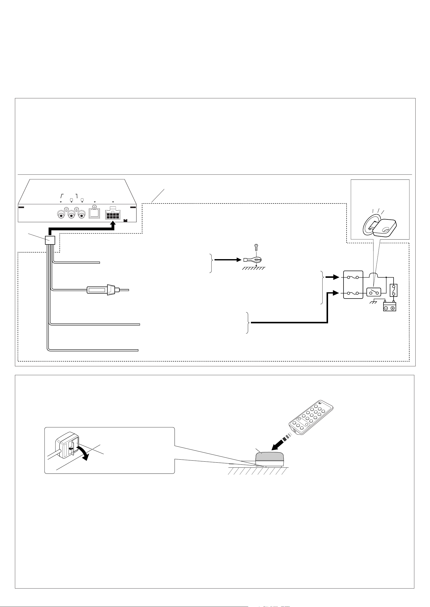
Typical Connections
Before connecting:
• Check the wiring in the vehicle carefully.
Incorrect connection may cause serious
damage to the unit.
1
Connect the colored leads of the power cord
in the order specified in the illustration
below.
2
Finally connect the wiring harness to the
unit.
AV OUTPUT
VIDEO
LAUDIOR
2
Black
Negro
Noir
黑色
Yellow *1
Amarillo *1
Jaune
*1
黃色*1
3A
Red
Rojo
Rouge
紅色
Blue with white stripe
Azul con rayas blancas
Bleu avec bande blanche
藍色帶白色條紋
Conexiones típicas
Antes de la conexión:
• Verifique atentamente el conexionado del
vehículo. Una conexión incorrecta podría
producir daños graves en la unidad.
1
Conecte los conductores de color del cable
de alimentación en el orden especificado
en la ilustración de abajo.
2
Por último, conecte el cable de
alimentación a la unidad.
1
POWER AV BUS
*1 Before checking the operation of this unit prior to installation, this lead must be connected, otherwise
power cannot be turned on.
*1 Antes de comprobar el funcionamiento de esta unidad antes de la instalación, deberá conectar este
conductor pues de lo contrario, no se podrá conectar la alimentación.
*1
Pour vérifier le fonctionnement de cet appareil avant installation, ce fil doit être raccordé, sinon l’appareil
ne peut pas être mis sous tension.
*1 本機未安裝時,在進行工作狀況檢查之前必須將此引線接上,否則無法啟動電源。
To metallic body or chassis of the car
A un cuerpo metálico o chasis del automóvil
À un corps métallique ou au châssis du véhicule
1
接至金屬車體或汽車底盤
To a live terminal in the fuse block connecting to the car battery (bypassing the ignition switch)
A un terminal activo del bloque de fusibles conectado a la batería del automóvil (desviando el
interruptor de encendido)
2
À une borne sous tension du porte-fusible connectée à la batterie de la voiture (en dérivant
l’interrupteur d’allumage)
接至保險絲單元的帶電端子,保險絲單元與車上電池相連接(用於旁路點火開關)
To an accessory terminal in the fuse block
A un terminal accesorio del bloque de fusibles
À une borne accessoire du porte-fusible
3
接至保險絲的附屬端子
To the remote control lead of JVC FM modulator KS-IF200 (for details, refer to the Instructions of KS-IF200) .
Al conductor de control remoto del modulador de FM JVC KS-IF200 (para los detalles, consulte las instrucciones del KS-IF200).
4
Au fil de commande à distance du modulateur FM JVC KS-IF200 (pour les détails, référez-vous aux instructions du KS-IF200).
接至 JVC FM 調節器 KS-IF200 的遙控引線(詳情參閱 KS-IF200 的使用說明書)。
Connexions typiques
Avant de commencer la connexion:
• Vérifiez attentivement le câblage du véhicule.
Une connexion incorrecte peut endommager
sérieusement l’appareil.
1
Connectez les fils colorés du cordon
d’alimentation dans l’ordre spécifié sur
l’illustration ci-dessous.
2
Finalement, connectez le faisceau de fils à
l’appareil.
*2
*2
*2 Not included with this unit.
*2 No suministrado con esta unidad.
*2
Non fourni avec cet appareil.
*2 不包括在本機中。
典型的接線方法
接線之前:
• 請仔細確認車內線路。不正確的接線會嚴重損
壞本機。
1
按下圖所示順序連接電源線裡的各色引線。
2
最後把配線束的插頭插接到本機。
Ignition switch
Interruptor de encendido
Interrupteur d’allumage
點火開關
Fuse block
Bloque de fusibles
Porte-fusible
保險絲單元
Connecting the remote sensor unit
• When used with any other monitor system
than KD-AV7000/KD-AV7005.
Double-faced adhesive tape
(supplied)
Cinta adhesiva de doble cara
(suministrada)
Ruban adhésif à double face (fourni)
雙面粘貼膠帶(附帶)
• Before installing, make sure the remote
controller functions properly with the remote
sensor unit placed in your selected position.
• Wipe clean the selected area sufficiently, and
affix the remote sensor unit to the place
firmly after removing the protective sheet
from the double-faced adhesive tape.
• Avoid any area on the dashboard, etc.
subjected to direct sunlight.
Select an area where the remote sensor unit
can receive remote signals through its front
face (sensing area).
Conexión de la unidad sensora
remota
• Cuando se utiliza con cualquier otro sistema de
monitor que no sea KD-AV7000/KD-AV7005.
• Antes de la instalación, asegúrese de que el
control remoto funcione correctamente con
la unidad sensora remota colocada en la
posición seleccionada por usted.
• Limpie suficientemente el lugar
seleccionado y fije firmemente la unidad
sensora remota sobre el sitio después de
retirar la lámina protectora de la cinta
adhesiva de doble cara.
• Evite cualquier lugar del tablero de
instrumentos que esté sujeto a la luz directa
del sol. El lugar de instalación debe permitir
a la unidad sensora remota recibir
directamente las señales a través de su cara
frontal (área de detección).
Connexion du capteur de
télécommande
• Utilisation avec un autre système de
moniteur que le KD-AV7000/KD-AV7005.
Sensing area
Area de detección
Zone de réception du capteur
感應區
Dashboard, etc.
Tablero de instrumentos, etc.
Tableau de bord, etc.
儀表板,及其他
• Avant de commencer l’installation, assurezvous que la télécommande fonctionne
correctement avec le capteur de
télécommande placé à l’endroit que vous
avez choisi.
• Nettoyez bien l’endroit choisi, et après avoir
retiré la feuille de protection du ruban adhésif
à double face, fixez-y fermement le capteur
de télécommande.
•Évitez les endroits du tableau de bord, etc.,
sujets à la lumière directe du soleil.
Choisissez un endroit où le capteur de
télécommande peut recevoir directement, par
l’avant, les signaux de la télécommande
(zone de réception du capteur).
連接遙感窗
• 當與 KD-AV7000/KD-AV7005 以外的監控系統
一起使用時。
0
1
5
K
-R
M
R
•
安裝之前,請確保遙控器可以正常地操作放
在您所選位置上的遙感窗。
• 充分清潔所選的地方,然後撕掉雙面粘貼膠
帶的保護膜後將遙感窗牢固在該處。
• 避免儀表板上的任何地方受到陽光直射。
選擇一個遙感窗能通過前表面收到遙控信號
的地方(感應區)。
5
Page 6

OPERATIONS
OPERACIONES
OPÉRATIONS
操作方法
The following operations cannot be
used when connecting this TV tuner
unit to KD-AV7000/KD-AV7005.
• When connecting to KD-AV7000/KD-AV7005,
refer to the Instructions supplied with them.
3
1
4
2
5
1 Standby/On button
Press to turns on and off the TV tuner unit.
2 TV CH (channel) 5 / ∞ button
• Press to search for the TV channels
(“SEARCH” appears). When a TV station
is received, search will stop.
• Press and hold to activate manual search
(“MANUAL” appears) for the TV station.
Then press repeatedly to change the TV
channels.
3 AUTO PRESET button
• Press to display the preset channel list.
• Press and hold to preset the receivable TV
stations automatically into the preset
number buttons (1 – 12).
4 DISP (display) button
Press to display the preset channel number
on the monitor.
12
5 Preset number buttons (1 – 12)
• Press to select the preset channel number
directly.
• Press and hold to store a TV station into
preset number (1 – 12).
Las siguientes operaciones no se
pueden realizar cuando se conecta
esta unidad de sintonizador de TV
al KD-AV7000/KD-AV7005.
• Para conectar al KD-AV7000/KD-AV7005,
consulte el manual de instrucciones
suministrado con los mismos.
1
2
CR2025
1 Botón Standby/On
Púlselo para encender y apagar la unidad
de sintonizador de TV.
2 Botón TV CH (canal) 5 / ∞
• Púlselo para buscar los canales de TV
(aparece “SEARCH”). La búsqueda cesa
cuando se recibe una emisora de TV.
• Púlselo y manténgalo pulsado para
activar la búsqueda manual (aparece
“MANUAL”) de las emisoras de TV. A
continuación, pulse repetidamente para
cambiar los canales de TV.
3 Botón AUTO PRESET
• Púlselo para visualizar la lista de canales
preajustados.
• Púlselo y manténgalo pulsado para
memorizar automáticamente las emisoras
de TV que se pueden recibir en los
botones numéricos de preajuste (1 – 12).
4 Botón DISP (pantalla)
Púlselo para visualizar en el monitor el
número de canal preajustado.
12
5
Botones numéricos de preajuste (1 – 12)
• Púlselos para seleccionar directamente
los números de canal preajustados.
• Púlselo y manténgalo pulsado para
almacenar una emisora de TV en el
número de preajuste (1 – 12).
Les opérations suivantes ne peuvent
pas être réalisées quand appareil
de tuner de télévision est connecté
au KD-AV7000/KD-AV7005.
• Lors d’une connexion au KD-AV7000/KDAV7005, référez-vous au manuel
d’instructions qui l’accompagne.
CAUTION / PRECAUCIÓN / ATTENTION / 注意:
DO NOT leave the remote controller in a place (such as
dashboards) exposed to direct sunlight for a long time.
Otherwise, it may be damaged.
3
NO deje el control remoto en un lugar expuesto a la luz
directa del sol (como los cubretableros) durante un tiempo
prolongado. De lo contrario, se podría dañar.
NE LAISSEZ PAS la télécommande dans un endroit (tel que
le tableau de bord) exposé à la lumière directe du soleil pendant
trop longtemps. Cela pourrait l’endommager.
切勿將遙控器長期放置在暴露於陽光直射的地方(如:儀表
板),否則會受到損傷。
1 Touche d’attente/mise sous tension
Appuyez sur cette touche pour mettre le
appareil de sous et hors tension.
2 Touche TV CH (canal) 5 / ∞
• Appuyez sur ces touches pour rechercher
des canaux de télévision (“SEARCH”
apparaît). Quand une station de télévision
est reçue, la recherche s’arrête.
• Maintenez ces touches pressées pour
mettre en service la recherche manuelle
(“MANUAL” apparaît) de station de
télévision. Puis appuyez répétitivement
pour changer le canal de télévision.
3 Touche AUTO PRESET
• Appuyez sur cette touche pour afficher la
liste des canaux préréglés.
• Maintenez cette touche pressée pour
prérégler automatiquement les stations de
télévision recevables sur les touches de
numéros préréglage (1 – 12).
4 Touche DISP (affichage)
Appuyez sur cette touche pour afficher le
numéro de canal préréglé sur le moniteur.
12
5 Touches de numéros de préréglage
(1 – 12)
• Appuyez sur ces touches pour choisir
directement un numéro de canal préréglé.
• Maintenez ces touches pressées pour
mémoriser une station de télévision sur un
numéro de préréglage (1 – 12).
將本電視調諧器連接至 KD-AV7000/
KD-AV7005 時,以下操作無法使用。
• 當連接至 KD-AV7000/KD-AV7005 時,參閱其
附帶的使用說明書。
1 待機∕開機鍵
按此鍵打開和關畢電視調諧器。
2 TV CH(頻道)5 / ∞ 鍵
• 按此鍵搜索電視頻道(“SEARCH”字樣
出現)。當一個電視臺被接收到時,搜索
停止。
• 按住此鍵啟動電視臺手動搜索
(“MANUAL”字樣出現)。然後反復按
以切換電視頻道。
3 AUTO PRESET 鍵
• 按此鍵顯示預設頻道清單。
• 按住此鍵將可接收的電視臺自動預設到預
設號碼鍵裡(1 _ 12)。
4 DISP(顯示)鍵
按此鍵在監控器上顯示預設頻道號碼。
12
5 預設號碼鍵(1 _ 12)
• 按此鍵直接選擇預設頻道號碼。
• 按住此鍵可將一個電視臺儲存到預設號碼
裡(1 _ 12)。
SPECIFICATIONS
TV TUNER UNIT
TV antenna jack × 4
AV bus terminal × 1
Remote sensor jack × 1
Output
Video: RCA pin × 1; 1 V(p-p), 75 Ω
Audio: RCA pin × 2; 150 mV(rms)
Dimensions (W × H × D):
163 mm × 28 mm × 122 mm
7
/16 in. × 1- 1/8 in. × 4- 13/16 in.)
(6-
Mass: 0.6 kg (1.4 lbs)
DIVERSITY ANTENNANA
Output impedance:
75 Ω × 4 (with mini plug)
Cord length: 5 m (16.63 ft)
Dimensions (approx.) (W × H × D):
440 mm × 490 mm × 18 mm
3
/8 in. × 19- 5/16 in. × 3/4 in.)
(17-
(without the cable)
Mass (each unit) (approx.):
220 g (0.49 lbs) (including the cable)
GENERAL
Channel coverage:
VHF: ch 2 – 13 UHF: ch 14 – 69
Power requirement
Operating voltage:
DC 14.4 V (11 V to 16 V allowance)
Grounding system: Negative ground
Allowable operating temperature:
0°C to +40°C (32°F to 104°F)
ESPECIFICACIONES
UNIDAD DE SINTONIZADOR DE TV
Jack de antena de TV × 4
Terminal AV bus × 1
Jack del sensor remoto × 1
Salida
Vídeo: clavija RCA x 1; 1 V(p-p), 75 Ω
Audio: clavija RCA x 2; 150 mV(rms)
Dimensiones (An × Al × Pr):
163 mm × 28 mm × 122 mm
Peso: 0,6 kg
ANTENA DE DIVERSIDAD
Impedancia de salida:
75
Ω
× 4 (con miniclavija)
Longitud del cable: 5 m
Dimensiones (aprox.) (An × Al × Pr):
440 mm × 490 mm × 18 mm
(sin el cable)
Peso (cada unidad) (aprox.):
220 g (incluyendo el cable)
GENERAL
Cobertura de canales:
VHF: Canales 2 – 13 UHF: Canales 14 – 69
Requerimiento de energía
Tensión de funcionamiento:
14,4 V CC (tolerancia 11 V a 16 V)
Sistema de puesta a tierra: Negativo a masa
Temperatura de funcionamiento admisible:
0°C a +40°C
SPÉCIFICATIONS
APPAREIL DE TUNER DE TÉLÉVISION
Prise d’antenne de télévision × 4
Prise de liaison AV
Prise de capteur de télécommande
Sortie
Vidéo: Cinch (RCA) × 1; 1 V(c-c), 75
Audio: Cinch (RCA) × 2; 150 mV(rms)
Dimensions (L
163 mm
Masse: 0,6
×
kg
ANTENNE DE RÉCEPTION EN DIVERSITÉ
Impédance de sortie:
Ω ×
4 (avec mini fiche)
75
Longueur du cordon: 5 m
Dimensions (approx.) (L × H × P):
440 mm
(sans le câble)
Masse (chaque élément) (approx.):
220
×
g
(avec le câble)
GÉNÉRAL
Couverture des canaux:
VHF: ca. 2 – 13 UHF: ca. 14 – 69
Alimentation
Tension de fonctionnement:
CC 14,4 V (11 V à 16 V admissibles)
Système de mise à la masse: négatif
Te mp ératures de fonctionnement admissibles:
0°C à +40°C
×
1
×
H × P):
28 mm × 122 mm
490 mm × 18 mm
×
1
Ω
規格
電視調諧器
電視天線插孔 × 4
AV 巴士端子 × 1
遙感窗插孔 × 1
輸出
視頻:針式 RCA × 1;1 V(p-p), 75 Ω
音頻:針式 RCA × 2;150 mV(rms)
體積(寬 × 高 × 深):
163 mm × 28 mm × 122 mm
重量:0.6 kg
智慧型天線
輸出阻抗:
75 Ω × 4(帶小插頭)
線長: 5 m
體積(大約)(寬 × 高 × 深):
440 mm × 490 mm × 18 mm
(不包括電纜)
重量(每個)(大約):
220 g(包括電纜)
一般信息
頻道範圍:
VHF:ch 2 – 13 UHF:ch 14 – 69
電源要求
工作電壓:
直流 14.4 V(允許 11 V 至 16 V)
接地方式:負極接地
允許的操作溫度:
0°C 至 +40°C
Design and specifications subject to change without
notice.
El diseño y las especificaciones se encuentran sujetos
a cambios sin previo aviso.
La conception et les spécifications sont sujettes à
changement sans notification.
6
設計和規格若有更改,恕不奉告。
Page 7

LVT1184-001A
[E]
KV-C1001
TV Tuner Unit : Instructions
Fernsehtuner-Gerät : Bedienungsanleitung
Appareil de tuner de télévision : Manuel d’instructions
TV-Tuner : Gebruiksaanwijzing
0904MNMMDWJEIN
EN, GE, FR, NL
© 2004 Victor Company of Japan, Limited
WARNINGS
• USE WITH DC 12 V NEGATIVE GROUND
VEHICLES.
If your vehicle does not have this system, a
voltage inverter is required, which can be
purchased at JVC IN-CAR ENTERTAINMENT
dealer.
• DO NOT INSTALL THE MONITOR IN A
LOCATION WHICH OBSTRUCTS DRIVING
AND VISIBILITY, OR WHERE APPLICABLE
LAWS AND REGULATIONS PROHIBIT THE
INSTALLATION.
• NEVER USE BOLTS OR NUTS FROM THE
VEHICLE’S SAFETY DEVICES FOR
INSTALLATION.
If bolts or nuts from the steering wheel, brakes
or other safety devices are used for
installation, it may cause an accident.
• INSTALL THE ANTENNA IN A PROPER
LOCATION.
Be sure to select a location for installation of
the antenna so that the antenna is not
protruding beyond the width or the front or
back of the vehicle. If it is protruding, it might
come into contact with a pedestrian or other
object and cause an accident.
• ATTACH THE WIRES CORRECTLY.
If the wiring is not correctly performed, it may
cause a fire or an accident. In particular, be
sure to run and secure the lead wire so that it
does not get tangled with a screw or the
moving portion of a seat rail.
To prevent short circuits, it is recommended
that you disconnect the battery’s negative
terminal and make all electrical connections
before installing the unit. If you are not sure
how to install this unit correctly, have it
installed by a qualified technician.
• Avoid installing the unit in the following
places.
– Where it would hinder your safety driving.
– Where it would be exposed to direct sunlight
or heat directly from the heater or placed in
an extremely hot place.
– Where it would be subject to rain, water
splashes or excessive humidity.
– Where it would be subject to dust.
– Where it would be positioned on an unstable
place.
– Where it could damage the car’s fittings.
– Where proper ventilation would not be
maintained, such as under a floor mat.
– Where it would be located near inflammable
objects (since heat is generated inside the
unit).
• Handle the Lithium coin battery (product
number: CR2025) with care.
– Store the battery in a place where children
cannot reach.
If a child accidentally swallows the battery,
consult a doctor immediately.
– Do not recharge, short, disassemble, or heat
the battery or dispose of it in a fire.
These behaviors may cause the battery to
be overheated, crack or fire.
– Do not leave the battery with other metallic
materials.
Doing this may cause the battery to be
overheated or cracked. It may cause a fire.
– When throwing away or saving the battery,
wrap it in tape and insulate; otherwise, the
battery may be overheated, crack or fire.
– Do not poke the battery with tweezers or
similar tools.
Doing this may cause the battery to be
overheated or cracked. It may cause a fire.
WARNUNGEN
• NUR FÜR VERWENDUNG MIT
FAHRZEUGEN MIT 12 V UND NEGATIVER
MASSE.
Verfügt Ihr Fahrzeug nicht über diese Anlage,
ist ein Spannungsinverter erforderlich, der bei
JVC Autoradiohändler erworben werden
kann.
• DEN MONITOR NICHT AN EINEM ORT
ANBRINGEN, WO ER BEIM FAHREN
STÖRT ODER DIE SICHT BESCHRÄNKT,
ODER WO ÖRTLICH GELTENDE GESETZE
ODER VORSCHRIFTEN DIE INSTALLATION
VERBIETEN.
• NIEMALS SCHRAUBEN ODER MUTTERN
DER SICHERHEITSVORRICHTUNGEN DES
FAHRZEUGS ZUM EINBAU VERWENDEN.
Wenn Schrauben oder Muttern von Lenkrad,
Bremsen oder anderen wichtigen
Fahrsystemen zum Einbau verwendet
werden, können Unfälle verursacht werden.
• DIE ANTENNE AN EINER GEEIGNETEN
STELLE MONTIEREN.
Immer sicherstellen, dass zum Einbau der
Antenne eine Stelle gewählt wird, wo die
Antenne nicht über die Breite oder das
vordere oder hintere Fahrzeugende
hinausragt. Wenn die Antenne hinausragt,
kann sie mit Fußgängern oder Gegenständen
in Berührung kommen und einen Unfall
verursachen.
• DIE DRÄHTE RICHTIG ANBRINGEN.
Wenn die Verdrahtung nicht richtig
ausgeführt wird, besteht die Gefahr von
Bränden oder Unfällen. Insbesondere muss
sichergestellt werden, dass der Leitungsdraht
so verlegt und befestigt wird, dass er nicht
mit einer Schraube oder einem beweglichen
Teil einer Sitzschiene in Berührung kommen
kann.
Um Kurzschlüsse zu verhindern, wird
empfohlen, die negative Batterieklemme
abzutrennen und alle elektrischen
Verbindungen vor dem Einbau der Einheit
vorzunehmen. Wenn bezüglich des richtigen
Einbaus der Einheit Zweifel bestehen, immer
einen qualifizierten Techniker um Rat fragen.
• Den Einbau der Einheit an den folgenden
Stellen vermeiden.
– Wo sie sicheres Fahren verhindert.
– Wo sie direktem Sonnenlicht oder direktem
Warmluftstrom von der Heitzung ausgesetzt
ist, oder an sehr heißen Stellen.
– Wo sie Regen, Wasserspritzern oder sehr
starker Luftfeuchtigkeit ausgesetzt ist.
– Wo sie Staub ausgesetzt ist.
– An einer instabilen Stelle.
– Wo sie Anbauteile des Fahrzeugs
beschädigen kann.
– Wo richtige Lüftung nicht gewährleistet
werden kann, wie etwa unter einer
Bodenmatte.
– Wo sich entflammbare Gegenstände in der
Nähe befinden (da in der Einheit Hitze
erzeugt wird).
• Die Lithiumknopfbatterie (Produktnummer:
CR2025) vorsichtig behandeln.
– Legen Sie die Batterie an einem Ort ab, wo
sie außer Reichweite kleiner Kinder ist.
Falls ein Kind versehentlich die Batterie
verschluckt, sofort einen Arzt rufen.
– Die Batterie nicht aufladen, kurzschließen,
zerlegen, erhitzen oder in ein Feuer werfen.
Dadurch kann sich die Batterie stark
erhitzen, bersten oder explodieren.
– Die Batterie nicht zusammen mit anderen
Metallgegenständen ablegen.
Dadurch kann sich die Batterie stark
erhitzen, bersten oder explodieren.
– Beim Entsorgen oder Aufbewahren der
Batterie diese mit Klebeband umwickeln;
andernfalls kann sich die Batterie stark
erhitzen, bersten oder explodieren.
– Die Batterie nicht mit Pinzetten oder
ähnlichen Werkzeugen anstoßen.
Dadurch kann sich die Batterie stark
erhitzen, bersten oder explodieren.
FRANÇAISDEUTSCHENGLISH
AVERTISSEMENT
• UTILISATION SUR LES VEHICULES DE
12 V CC À MASSE NÉGATIVE.
Si votre véhicule n’offre pas ce type
d’alimentation, il vous faut un convertisseur de
tension, que vous pouvez acheter chez un
revendeur d’autoradios JVC.
• N’INSTALLEZ PAS LE MONITEUR DANS
UN ENDROIT QUI GÈNE LA CONDUITE ET
LA VISIBILITÉ, OU DANS UN ENDROIT
INTERDIT PAR LE CODE DE LA ROUTE ET
LA LOI.
• N’UTILISEZ JAMAIS POUR
L’INSTALLATION DES BOULONS OU DES
ÉCROUS PROVENANT DES DISPOSITIFS
DE SÉCURITÉ DU VEHICULE.
Si vous utilisez pour l’installation des boulons
et des écrous du volant, des freins ou d’autres
dispositifs de sécurités, cela risquerait de
provoquer des accidents.
• INSTALLEZ L’ANTENNE DANS UN
EMPLACEMENT ADEQUAT.
Choisissez correctement l’emplacement
d’installation de l’antenne de sorte qu’elle ne
dépasse pas par les côtés, l’avant ou l’arrière
du véhicule. Si l’antenne dépasse, elle peut
heurter un piéton, ou un objet quelconque et
risquer de causer un accident.
• ATTACHER LES FILS CORRECTEMENT.
Si le câblage n’est pas réalisé correctement,
cela risque de provoquer un incendie ou autre
accident. Assurez-vous, en particulier, de tirer
et d’attacher les fils de sorte qu’ils ne
s’accrochent pas à une vis ni ne se coincent
dans les parties mobiles des rails des sièges.
Pour éviter les courts-circuits,
recommandons que vous déconnectiez la
borne négative de la batterie et réalisiez
toutes les connexions électriques avant
d’installer l’appareil. Si vous n’êtes pas sûr de
savoir comment installer cet appareil
correctement, faites-le installer par un
technicien qualifié.
• Évitez d’installer l’appareil dans les
endroits suivants.
– Où il peut gêner la conduite de la voiture.
– Où il est exposé à la lumière directe du
soleil, à la chaleur directe du chauffage ou
placé dans un endroit très chaud.
– Où il est sujet à la pluie, aux éclaboussures
ou à une humidité excessive.
– Où il est sujet à la poussière.
– Où il est positionné dans un endroit instable.
– Où il peut endommager les accessoires de
la voiture.
– Où une ventilation correcte ne peut pas être
obtenue, comme sous un tapis de sol.
– Près d’objets inflammables (car de la
chaleur est produite à l’intérieur de
l’appareil).
• Manipulez de la pile-bouton au Lithium
(produit numéro: CR2025) avec précaution.
– Conservez la pile dans un endroit hors de la
portée des enfants.
Si un enfant avalait accidentellement la pile,
consultez un médecin immédiatement.
– Ne recherchez pas, ne court-circuitez pas,
ne démontez pas ni ne chauffez la pile et ne
la jetez pas dans le feu.
Cela pourrait entraîner une surchauffe de la
pile, un éclatement ou un incendie.
– Ne laissez pas la pile avec d’autres objets
métalliques.
Cela pourrait entraîner une surchauffe de la
pile, un éclatement ou un incendie.
– Pour vous débarrasser de la pile ou la
conserver, enveloppez-la de ruban adhésif
et isolez-la, sinon cela pourrait entraîner
une surchauffe de la pile, un éclatement ou
un incendie.
– Ne piquez pas la pile avec des pinces ou un
outil similaire.
Cela pourrait entraîner une surchauffe de la
pile, un éclatement ou un incendie.
nous
NEDERLANDS
WAARSCHUWINGEN
• GEBRUIK UITSLUITEND MET 12 VOLT
NEGATIEF GEAARDE AUTO’S.
Als uw auto niet is uitgerust met een dergelijk
systeem, is een spanningsomzetter vereist. Dit
instrument kan worden aangeschaft bij JVC car
audio dealers.
• INSTALLEER DE MONITOR NIET OP
PLAATSEN WAAR DE MONITOR HET
BESTUREN VAN DE AUTO EN ZICHT KAN
HINDEREN, OF OP PLAATSEN DIE DOOR
WETTEN OF LOKALE REGLEMENTEN
VERBODEN ZIJN.
• GEBRUIK VOOR HET INSTALLEREN
NOOIT BOUTEN OF MOEREN VAN
VEILIGHEIDSVOORZIENINGEN VAN DE
AUTO.
Het gebruik van bouten of moeren van het stuur, de
remmen of andere veiligheidsvoorzieningen van de
auto kan ernstige ongelukken tot gevolg hebben.
• INSTALLEER DE ANTENNE OP EEN
GESCHIKTE PLAATS.
Kies een geschikte plaats voor het monteren van de
antenne zodat deze niet te veel in de breedte, of
aan de voor- of achterkant van de auto uitsteekt.
Een te ver uitstekende antenne kan voetgangers,
fietser of andere voorwerpen raken met mogelijk
ernstige ongelukken tot gevolg.
• SLUIT DE DRADEN JUIST AAN.
Een verkeerde bedrading kan brand of ongelukken
veroorzaken. Let vooral op bij het leiden en
vastzetten van draden en bundels zodat deze niet
door schroeven worden vastgekneld of onder
bewegende onderdelen, bijvoorbeeld het
schuifmechanisme van stoelen, verstrikt raken.
Voorkom kortsluiting, en ontkoppel derhalve
de negatieve accupool alvorens alle elektrische
verbindingen te maken en het toestel te installeren.
Laat het toestel door een erkend technicus
installeren indien u niet zeker weet of u het zelf op
de juiste wijze kunt.
• Vermijd de volgende plaatsen voor het
installeren van het toestel.
– Waar het de veiligheid voor het rijden kan
hinderen.
– Waar het aan het directe zonlicht of hitte van de
verwarming wordt blootgesteld en op andere
warme plaatsen.
– Op plaatsen die aan regen, water, spatten of
extreme vochtigheid onderhevig zijn.
– Op zeer stoffige plaatsen.
– Op een plaats die niet stevig of instabiel is.
– Waar het toestel onderdelen van de auto zou
kunnen beschadigen.
– Op een plaats waar het toestel niet goed kan
worden geventileerd, bijvoorbeeld onder de
vloermat.
– In de buurt van ontvlambare voorwerpen (daar er
hitte in het toestel wordt opgewekt).
• Wees voorzichtig met de lithium
knoopbatterij (productnummer: CR2025)
– Bewaar de batterij buiten het bereik van kleine
kinderen.
Indien een batterij per ongeluk wordt ingeslikt,
moet u direct een arts raadplegen.
– Laad de batterij niet op, sluit niet kort,
demonteer niet, verwarm niet en gooi niet in een
vuur.
De batterij zou anders mogelijk kunnen
oververhitten, barsten of een brand veroorzaken.
– Bewaar de batterij niet samen met andere
metalen voorwerpen.
De batterij zou anders mogelijk kunnen
oververhitten, barsten of een brand veroorzaken.
– Wikkel de batterij om met band en isoleer goed
alvorens weg te gooien of langdurig op te slaan.
De batterij zou anders mogelijk kunnen
oververhitten, barsten of een brand veroorzaken.
– Steek niet met een tang, etc. in de batterij.
De batterij zou anders mogelijk kunnen
oververhitten, barsten of een brand veroorzaken.
1
Page 8

Parts list
The following parts are provided with this unit.
After checking them, please set them correctly.
Brackets
Bügel
Supports
Beugels
Fixing screws—M4 x 8 mm
Befestigungsschrauben—M4 x 8 mm
Vis de fixation—M4 x 8 mm
Bevestigingsschroeven—M4 x 8 mm
Teileliste
Die folgenden Teile werden mit dieser Einheit
mitgeliefert.
Nach dem Prüfen bitte richtig ablegen.
Remote controller
Fernbedienung
Télécommande
Afstandsbediening
AV bus cable
AV-Bus-kabel
Câble de liaison AV
AV-buskabel
Liste des pièces
Les pièces suivantes sont fournies avec cet
appareil.
Après vérification, veuillez les installer
correctement.
Power cord
Stromkabel
Cordon d’alimentation
Stroomsnoer
Onderdelenlijst
Bij dit toestel zijn de volgende onderdelen geleverd.
Controleer of alles aanwezig is en gebruik
vervolgens als beschreven.
CR2025
Battery
Batterie
Pile
Batterij
INSTALLATION
• The following illustrations show typical
RM-RK510
INSTALLATION
• Die folgenden Abbildungen zeigen die
installation.
If you have any questions or require
information regarding installation kits, consult
your JVC IN-CAR ENTERTAINMENT dealer
or a company supplying kits.
When used with KD-AV7001/KD-AV7005:
Bei Verwendung mit KD-AV7001/KD-AV7005:
Utilisation avec le KD-AV7001/KD-AV7005:
Bij gebruik van de KD-AV7001/KD-AV7005:
KD-AV7001/KD-AV7005 (separately purchased)
KD-AV7001/KD-AV7005 (getrennt gekauft)
KD-AV7001/KD-AV7005
(à acheter séparément)
KD-AV7001/KD-AV7005
(los verkrijgbaar)
Remote sensor unit with double-faced adhesive tape
Fernbedienungssensor mit doppelseitigen Klebeband
Capteur de télécommande avec ruban adhésif à double face
Afstandsbedieningssensor met dubbelzijdig plakband
typische Installation.
Bei irgendwelchen Fragen oder wenn Sie
Informationen hinsichtlich des Einbausatzes
brauchen, wenden Sie sich an ihren JVC
Autoradiohändler oder ein Unternehmen das
diese Einbausätze vertreibt.
Diversity antenna
Diversity-Antenne
Antenne de réception en diversité
Geleiding-antenne
Diversity antennas with a cleaner
Diversity-Antennen mit einem Reiniger
Antenne de réception en diversité avec papier
nettoyant
Geleiding-antennes met reiniger
INSTALLATION
• L’illustration suivante montre une installation
typique.
Si vous avez des questions ou avez
besoin d’information sur des kits d’installation,
consulter votre revendeur d’autoradios JVC
ou une compagnie d’approvisionnement.
INSTALLEREN
• De volgende afbeeldingen tonen een standaardinstallatievoorbeeld.
Neem bij vragen of voor meer bijzonderheden
over inbouwpakketten contact op met uw JVC car
audio dealer of een dealer of een bedrijf dat
inbouwpakketten levert.
When used with another monitor system:
Bei Verwendung mit einem anderen Monitorsystem:
Utilisation avec un autre système de moniteur:
Bij gebruik van een ander monitorsysteem:
Remote sensor unit
Fernbedienungssensoreinheit
Capteur de télécommande
Diversity antenna
Diversity-Antenne
Antenne de réception en diversité
Geleiding-antenne
Afstandsbedieningssensor
Monitor system (separately purchased)
Monitorsystem (getrennt gekauft)
Système de moniteur (à acheter séparément)
Monitorsysteem (los verkrijgbaar)
Installing the unit
While mounting the unit, be sure to use the
tapping screws (not supplied) of appropriate
length so that they will not damage any parts of
the car.
Fixing screws—M4 x 8 mm
Befestigungsschrauben—M4 x 8 mm
Vis de fixation—M4 x 8 mm
Bevestigingsschroeven—M4 x 8 mm
TV tuner unit (in trunk)
Fernsehtuner-Gerät (im Kofferraum)
Appareil de tuner de télévision (dans le coffre)
TV-tuner (in de kofferbak)
Installieren der Einheit
Beim Anbringen der Einheit sicherstellen,
Schneidschrauben (nicht mitgeliefert)
geeigneter Länge zu verwenden, so dass
diese nicht Fahrzeugteile beschädigen.
TV tuner unit (under the passenger’s seat)
Fernsehtuner-Gerät (unter dem Beifahrersitz)
Appareil de tuner de télévision (sous le siège du passager)
TV-tuner (onder de passagiersstoel)
Instalation de l’appareil
Pour installer
des vis autotaraudeuses (non fournies) d’une
longueur appropriée de façon à n’endommager
aucune partie de la voiture.
l’appareil, assurez-vous d’utiliser
Tapping screws (not supplied)
Schneidschrauben (nicht mitgeliefert)
Vis autotaraudeuses (non fournies)
Tapse schroeven (niet bijgeleverd)
Installeren van het toestel
Voor het monteren van het toestel, moet u beslist
tapse schroeven (niet bijgeleverd) met een geschikte
lengte gebruiken zodat er geen onderdelen van de
auto worden beschadigd.
Bracket
Bügel
Support
Beugel
Floor
Boden
Plancher
Vloer
2
Page 9

Installing the antenna
Before installing:
• The diversity antenna supplied with this unit is
designed specifically for use with JVC TV
tuner unit. (It cannot be connected to the car
radio.)
• Do not rub the antenna or the antenna’s cable
with alcohol, benzine, thinner, gasoline or
other volatile substances.
• Attach to the inside of the car window glass.
• Be sure to wipe the window surface where the
antenna will be attached with the cleaner
(supplied) to remove moisture, dirt, dust, wax,
oil or other substances. (If there is moisture,
oil or other wet substances on the attachment
surface, the attachment tape will not stick well
and easily come off.)
• Identify the exact attachment location and
confirm that the adhesive surfaces (antenna
base and attachment parts) will not be placed
on a heating wire, glass antenna or wiper
motor.
Installieren der Antenne
Vor dem Installieren:
• Die mit dieser Einheit mitgelieferte DiversityAntenne ist spezifisch zur Verwendung mit dem
JVC-Fernsehtuner-Gerät ausgelegt. (Sie kann
nicht an das Autoradio angeschlossen werden).
• Nicht die Antenne oder das Antennenkabel
mit Alkohol, Benzol, Terpentin, Benzin oder
anderen flüchtigen organischen Substanzen
abreiben.
• Innen am Fahrzeugfensterglas anbringen.
• Die Fensterfläche, wo die Antenne angebracht
werden soll, mit dem Reiniger (mitgeliefert)
abreiben, um Feuchtigkeit, Schmutz, Staub,
Wachs oder andere Substanzen zu entfernen.
(Falls Feuchtigkeit, Öl oder andere nasse
Substanzen auf der Anbringungsoberfläche
vorhanden sind, klebt das Befestigungsband
nicht richtig und löst sich leicht ab).
• Die genaue Anbringungsposition festlegen
und bestätigen, dass die
Anbringungsoberflächen (Antennenbasis und
Anbringungsteile) nicht auf Heizungsdraht,
Glasantenne oder Wischermotor platziert sind.
Installation de l’antenne
Avant l’installation:
• L’antenne de réception en diversité fournie avec
cet appareil est spécialement conçue pour être
utilisé avec un tuner de télévision JVC. (Elle ne
peut pas être connectée à l’autoradio.)
• Ne frottez pas l’antenne ou le câble d’antenne
avec de l’alcool, de la benzine, du diluant, de
l’essence ou toutes autres substances volatiles.
• Fixez-la à l’intérieur de la vitre de la voiture.
• N’oubliez pas de frotter la surface de la vitre
où doit être fixée l’antenne avec le nettoyant
(fourni) afin d’enlever l’humidité, les saletés, la
poussière, la cire, les traces de graisse et
toutes autres impuretés. (Si de l’humidité, des
traces de graisse ou d’autres substances
humides subsistent sur la surface de fixation,
les surfaces adhésives n’adhéreront pas
correctement et finiront par se détacher.)
• Repérer exactement l’emplacement de fixation
et vérifiez que les surfaces adhésives (base de
l’antenne et pièces de fixation) ne sont pas
placées sur un fil chauffant, l’antenne de vitre,
ou le moteur d’essuie-glace.
Installeren van de antenne
Alvorens te installeren:
• De bij dit toestel geleverde geleiding-antenne is
exclusief ontworpen voor het gebruik met de JVC
TV-tuner. (Deze antenne kan niet met de autoradio
worden verbonden).
• Reinig de antenne of de antennekabel niet met
alcohol, benzeen, thinner, benzine of andere
vluchtige middelen.
• Bevestig aan de binnenkant op het glas van de
autoruit.
• Veeg het ruitoppervlak waar de antenne moet
worden bevestigd beslist goed schoon met de
reiniger (bijgeleverd) zodat er geen vocht, stof,
vuil, was, olie of andere middelen meer op het ruit
zijn. (Het plakband zal niet goed plakken en
gemakkelijk los komen indien er vocht, olie of
andere middelen op het ruit zijn).
• Bepaal de exacte plaats voor het bevestigen van de
antenne en controleer dat de te bevestigen
onderdelen (antennebasis en
bevestigingsonderdelen) niet over
ruitverwarmingsdraden, ruitantenne of
wissermotor komen.
CAUTION
Since there may be legal regulations defining
the permissible installation locations for the
monitor system which differ by country or by
state, be sure to install the monitor in a location
complying with any such laws.
1
Peel off the cover paper from the antenna
base and attach to the surface.
2
Peel off the cover paper from the
attachment parts in turn and attach to the
surface.
Attachment parts
Anbringungsteile
Pièces de fixation
Bevestigingsonderdelen
Antenna base
Antennenbasis
Base de l’antenne
Antennebasis
ACHTUNG
Da örtlich geltende gesetzliche Vorschriften die
zulässigen Stellen zur Anbringung des
Monitorsystems festlegen können, müssen Sie
sich zuerst über alle zutreffenden Vorschriften
informieren und diese befolgen.
1
Das Deckpapier von der Antennenbasis
abziehen und an der Oberfläche anbringen.
2
Das Deckpapier von den Anbringungsteilen
der Reihe nach abziehen und an der
Oberfläche anbringen
1
Peel off the cover paper.
Das Deckpapier abziehen.
Décollez le papier
protecteur.
Verwijder het
beschermpapier.
2
Peel off the cover paper.
Das Deckpapier abziehen.
Décollez le papier protecteur.
Verwijder het beschermpapier.
ATTENTION
Il peut exister des réglementations définissant
les emplacements d’installation autorisés pour
un moniteur et celles-ci peuvent varier d’une
région ou d’un pays à l’autre. Assurez-vous
d’installer le moniteur dans un endroit conforme
à ces lois.
1
Décollez le papier protecteur du ruban
adhésif de la base de l’antenne et collez
celle dernière sur la surface.
2
Décollez, l’un après l’autre, le papier
protecteur des pièces de fixation et collez
ces dernières sur la surface.
Attachment location / Anbringungsstelle /
Emplacement de fixation / Plaats voor bevestigen
Example of installation, side window
Installationsbeispiel, Seitenfenster
Exemple d’installation sur la vitre latérale
In dit voorbeeld wordt het zijruit gebruikt
LET OP
Er zijn mogelijk bepaalde wetten of regels voor de
installatieplaats van monitors. Deze wetten en regels
verschillen per land of gebied. Installeer de monitor
beslist op plaatsen die niet in strijd met deze regels
of wetten zijn.
1
Verwijder het beschermpapier van de
antennebasis en bevestig op het oppervlak.
2
Verwijder het beschermpapier achtereenvolgend
van de verschillende bevestigingsonderdelen en
bevestig op het oppervlak.
• When the attachment surface overlaps with an electrode
Wenn sich die Anbringungsoberfläche mit einer Elektrode überlappt
Si surface de fixation chevauche une électrode
Indien het bevestigingsoppervlak een elektrode overlapt
Electrode
Elektrode
Électrode
Elektrode
Heating wires
Heizdrähte
Fils chauffants
Verwarmingsdraden
Attach the antenna to either the left or right of the
electrode.
Die Antenne links oder rechts von der Elektrode
anbringen.
Fixez l’antenne soit à gauche, soit à droite de
l’électrode.
Bevestig de antenne aan de linker- of rechterkant van
de elektrode.
• Installing the antenna cord
Installieren des Antennenkabels
Installation du cordon d’antenne
Installeren van het antennesnoer
Install the cord from the antenna to the TV tuner unit through the interior trim and under the
carpet, and secure it using the cord clampers and mirror mats.
• When the attachment surface interferes with a rear wiper motor or a
high-mounted brake light
Wenn die Anbringungsoberfläche mit einem
Heckscheibenwischermotor oder einer hoch angebrachten
Bremsleuchte in Behinderung kommt
Si la surface de fixation gêne le moteur d’essuie-glace ou un feu de
freinage surélevé
Indien het bevestigingsoppervlak te dicht bij het mechanisme van de
achterwisser of een hoog-gemonteerd remlicht is
Move the antenna’s attachment position upwards to
avoid interference.
Die Antennenanbringposition weiter nach oben
schieben, um Behinderungen zu vermeiden.
Déplacez la position d’installation de l’antenne vers
le haut jusqu’à ce qu’elle ne gêne plus.
Verplaats de positie voor het bevestigen van de antenne
iets omhoog zodat er voldoende ruimte is.
Das Kabel von der Antenne zum Fernsehtuner-Gerät durch die Innenverkleidung und unter dem
Teppichboden verlegen und mit den Kabelklemmen und Spiegelmatten befestigen.
Tirez le cordon de l’antenne à partir du tuner de télévision en le faisant passer par la garniture
intérieure et sous le tapis de sol et fixez-le en utilisant les colliers de cordon et les garnitures
éponges.
Leid het snoer van de antenne via de interieurafwerking en onder de vloermat naar de TV-tuner en zet met
draadklemmen en draadmatjes vast.
Cord clampers (separately purchased)
Kabelklemmen (getrennt gekauft)
Colliers de cordon (à acheter séparément)
Draadklemmen (los verkrijgbaar)
Mirror mats (separately purchased)
Spiegelmatten (getrennt gekauft)
Garnitures éponges (à acheter séparément)
Draadmatjes (los verkrijgbaar)
3
Page 10

REMOTE
SENSOR
RESET
3214
AV OUTPUT
R
L
VIDEO
POWER AV BUS
AUDIO
TV ANTENNA
TV TUNER UNIT KV-C1001
MULTIMEDIA DVD/CD RECEIVER WITH REMOVABLE MONITOR HIDEAWAY UNIT
AV INPUT 1
L
R
AUDIO
FM / AM ANTENNA
POWER
BACKCAMERA
REMOTE
CENTER
SPEAKER
CENTER
SUB
WOOFER
L
R
REAR
L
R
FRONT
VIDEO
AV INPUT 2
L
R
AUDIO
VIDEO TO CHANGER AV BUS TO MAIN UNIT
PRE OUT
AUDIO
VIDEO L R
AV OUTPUT
REMOTE
SENSOR
RESET
3214
AV OUTPUT
R
L
VIDEO
POWER AV BUS
AUDIO
TV ANTENNA
TV TUNER UNIT KV-C1001
ENGLISH
DEUTSCH
FRANÇAIS
NEDERLANDS
ELECTRICAL CONNECTIONS
ELEKTRISCHE VERBINDUNGEN
When used with KD-AV7001/KD-AV7005:
Bei Verwendung mit KD-AV7001/KD-AV7005:
Utilisation avec le KD-AV7001/KD-AV7005:
Bij gebruik met de KD-AV7001/KD-AV7005:
Antenna element
Antennenelement
Élément d’antenne
Antenne-element
Antenna base
Antennenbasis
Base de l’antenne
Antennebasis
Cord protector *1
Kabelschutz *1
Protecteur de cordon
Draadbeschermer *1
*1
CONNEXIONS ELECTRIQUES
ELEKTRISCHE VERBINDINGEN
When used with another monitor system:
Bei Verwendung mit einem anderen Monitorsystem:
Utilisation avec un autre système de moniteur:
Bij gebruik met een ander monitorsysteem:
Hideaway unit (supplied for KD-AV7001/KD-AV7005)
Versteckte Einheit (für KD-AV7001/KD-AV7005 mitgeliefert)
Appareil satellite (fourni avec le KD-AV7001/KD-AV7005)
Verborgen toestel (bijgeleverd voor de KD-AV7001/KD-AV7005)
AV bus cable
(supplied) *2
AV-Bus-kabel (mitgeliefert) *2
Câble de liaison AV
(fourni)
*2
AV-buskabel (bijgeleverd) *2
Monitor system (separately purchased)
Monitorsystem (getrennt gekauft)
Système de moniteur (à acheter séparément)
Monitorsysteem (los verkrijgbaar)
See “Typical Connections” on page 5.
Siehe „Typische Anschlüsse“ auf Seite 5.
Voir “Connexions typiques” à la page 5.
Zie “Standaardverbindingen” op bladzijde 5.
Remote sensor unit
Fernbedienungssensoreinheit
Capteur de
télécommande
Afstandsbedieningssensor
*3
*1 Use this to protect the cord (not to be pinched
with the door, etc.)
*2 For controlling KV-C1001 through KD-AV7001/
KD-AV7005, this connection is only required. For
other connections, refer to the manual supplied
for KD-AV7001/KD-AV7005.
*3 Reset the unit after installation is finished by
pressing in with a ball-point pen or a similar
tool.
TROUBLESHOOTING
When used with any other monitor system
than KD-AV7001/KD-AV7005.
• TV tuner does not work at all.
* Is the remote sensor unit connected
correctly?
• No sound is heard.
* Have you adjusted the volume level on the
monitor?
• Picture does not come on the screen.
* Is the correct input selected on the monitor?
• The fuse blows.
* Are the red, yellow, and black leads
connected correctly?
• Power cannot be turned on.
* Is the yellow lead connected?
• TV stations cannot be received.
* Is the area setting (see page 6) correct?
*1 Dies zum Schutz des Kabels verwenden (zum
Verhindern von Einklemmen mit der Tür usw.)
*2 Zur Steuerung von KV-C1001 über KD-AV7001/
KD-AV7005 ist nur dieser Anschluss erforderlich.
Für andere Anschlüsse siehe mit KD-AV7001/
KD-AV7005 mitgelieferte Anleitung.
*3 Die Einheit nach der Installation durch
Drücken mit einem Kugelschreiber oder
ähnlichen Gegenstand rücksetzen.
STÖRUNGSSUCHE
Bei Verwendung mit einem anderen
Monitorsystem als KD-AV7001/KD-AV7005.
• Fernsehtuner funktioniert überhaupt nicht.
* Ist die Fernbedienungssensoreinheit richtig
angeschlossen?
• Kein Ton.
* Die Lautstärke am Monitor einstellen?
• Kein Bild im Bildschirm.
* Ist der richtige Eingang am Monitor gewählt?
• Sicherung brennt durch.
* Sind die roten, gelben und schwarzen
Leitungen richtig angeschlossen?
• Gerät schaltet nicht ein.
* Ist die gelbe Leitung angeschlossen?
• TV-Sender können nicht empfangen
werden.
* Ist die Bereichseinstellung (siehe Seite 6)
richtig?
*3
*1
Pour protéger le cordon (afin qu’il ne se prenne
pas dans la porte, etc.)
*2
Cette connexion est nécessaire pour commander
le KV-C1001 à travers le KD-AV7001/KD-AV7005.
Pour les autres connexions, référez-vous au
manuel fourni avec le KD-AV7001/KD-AV7005.
*3 Réinitialisez l’appareil une fois que
l’installation est terminée en appuyant avec un
stylo bille ou un objet similaire.
EN CAS DE DIFFICULTÉS
Utilisation avec un autre système de
moniteur que le KD-AV7001/KD-AV7005.
• Le tuner de télévision ne fonctionne pas
du tout.
*
Le capteur de télécommande est-il connecté
correctement?
• Il n’y a pas de son.
*
Avez-vous ajusté le niveau de volume du
moniteur?
• Aucune image n’apparaît sur l’écran.
Est-ce que l’entrée correcte a été choisie sur
*
le moniteur?
• Le fusible saute.
*
Les fils rouge, jaune et noir sont-ils raccordés
correctement?
• L’appareil ne peut pas être mis sous
tension.
*
Le fil jaune est-il raccordé?
• Les stations de télévision ne peuvent pas
être reçues.
*
Le réglage de la région (voir page 6) est-il
correct?
4
*1 Gebruik ter bescherming van de draden (zodat deze
niet door portieren, etc. worden vastgekneld).
*2 Voor bediening van de KV-C1001 via de KD-AV7001/
KD-AV7005, is deze verbinding vereist. Zie de
gebruiksaanwijzing van de KD-AV7001/KD-AV7005
voor details aangaande de andere verbindingen.
*3 Stel het toestel na het installeren terug door
met een pen of dergelijk voorwerp op de
terugsteltoets te drukken.
OPLOSSEN VAN PROBLEMEN
Bij gebruik met een ander monitorsysteem
dan de KD-AV7001/KD-AV7005.
• TV-tuner werkt geheel niet.
* Is de afstansbedieningssensor juist aangesloten?
• Geen geluid.
* Is het juiste volume voor de monitor ingesteld?
• Geen beeld op het scherm.
* Is de juiste ingang voor de monitor gekozen?
• Zekering brandt door.
* Zijn de rode, gele en zwarte draden juist
verbonden?
• Stroom kan niet worden ingeschakeld.
* Is het gele draad juist aangesloten?
• TV-zenders kunnen niet worden
ontvangen.
* Is de instelling voor het gebied (zie bladzijde 6)
juist?
Page 11

RM-RK510
POWER AV BUS
AV OUTPUT
VIDEO
LAUDIOR
4
1
2
3
3A
The following is not required when
connecting this TV tuner unit to
KD-AV7001/KD-AV7005.
This unit is designed to operate on 12 V DC,
NEGATIVE ground electrical systems. If your
vehicle does not have this system, a voltage
inverter is required, which can be purchased at
JVC IN-CAR ENTERTAINMENT dealer.
• Replace the fuse with one of the specified
ratings. If the fuse blows frequently, consult
your JVC IN-CAR ENTERTAINMENT dealer.
• To prevent short-circuit, cover the terminals of
the UNUSED leads with insulating tape.
Folgendes ist bei Anschluss dieses TVTuners an KD-AV7001
/KD-AV7005
nicht erforderlich.
Diese Einheit ist zum Betrieb mit elektrischen
Anlagen mit 12 V gleichstrom, NEGATIVE
Masse ausgelegt. Verfügt Ihr Fahrzeug nicht
über diese Anlage, ist ein Spannungsinverter
erforderlich, der bei JVC Autoradiohändler
erworben werden kann.
• Die Sicherung mit einer der entsprechenden
Nennleistung ersetzen. Brennt die Sicherung
häufig durch, wenden Sie sich an ihren JVC
Autoradiohändler.
• Um Kurzschlüsse zu verhindern, die
Klemmen der NICHT VERWENDETEN
Leitungen mit Isolierband abdecken.
Ce qui suit n’est pas requis lors de
la connexion de appareil de tuner
de télévision au KD-AV7001/
KD-AV7005.
Cet appareil est conçu pour fonctionner sur des
sources de courant continu de
masse
NÉGATIVE
. Si votre véhicule n’offre pas
ce type d’alimentation, il vous faut un
convertisseur de tension, que vous pouvez
acheter chez un revendeur d’autoradios JVC.
• Remplacer le fusible par un de la valeur
précisée. Si le fusible saute souvent, consulter
votre revendeur d’autoradios JVC.
• Pour éviter les courts-circuits, couvrir les
bornes des fils qui ne sont PAS UTILISÉS
avec de la bande isolante.
12 V CC à
Het volgende is niet vereist indien u
deze TV-tuner met de KD-AV7001/
KD-AV7005 verbindt.
Dit toestel is ontworpen voor gebruik met 12 VOLT
gelijkstroom NEGATIEF geaarde elektrische
systemen. Als uw auto niet is uitgerust met een
dergelijk systeem, is een spanningsomzetter vereist.
Dit instrument kan worden aangeschaft bij JVC car
audio dealers.
• Vervang de zekering door een exemplaar met het
aangegeven vermogen. Als de zekering vaak
doorslaat, moet u uw JVC car audio dealer
raadplegen.
• Voorkom kortsluiting en bedek de aansluitingen en
stekkers van de NIET-GEBRUIKTE draden met
isolatieband.
Typical Connections
Before connecting:
• Check the wiring in the vehicle carefully.
Incorrect connection may cause serious
damage to the unit.
1
Connect the colored leads of the power cord
in the order specified in the illustration
below.
2
Finally connect the wiring harness to the
unit.
2
Black
Schwarz
Noir
Zwart
Yellow *1
Gelb *1
Jaune
*1
Geel *1
Red
Rot
Rouge
Rood
Blue with white stripe
Blau mit weißem Streifen
Bleu avec bande blanche
Blauw met witte streep
Typische Anschlüsse
Vor dem Anschluss:
• Die Verdrahtung im Fahrzeug sorgfältig
prüfen. Falscher Anschluss kann zu
schweren Schäden an der Einheit führen.
1
Die farbigen Adern des Stromkabels in der
Reihenfolge anschließen, wie in der
Abbildung unten gezeigt.
2
Zuletzt den Verdrahtungskabelbaum an der
Einheit anschließen.
1
*1 Before checking the operation of this unit prior to installation, this lead must be connected, otherwise
power cannot be turned on.
*1 Vor dem Prüfen der richtigen Funktion dieser Einheit vor der Installation muss diese Leitung
angeschlossen sein, andernfalls kann das Gerät nicht eingeschaltet werden.
*1
Pour vérifier le fonctionnement de cet appareil avant installation, ce fil doit être raccordé, sinon l’appareil
ne peut pas être mis sous tension.
*1 Voor het controleren van de werking van het toestel alvorens het toestel werkelijk te installeren, moet dit draad
worden verbonden. De stroom kan anders namelijk niet worden ingeschakeld.
To metallic body or chassis of the car
An Metallic-Karosserie oder Chassis des
Fahrzeugs
À un corps métallique ou au châssis du véhicule
Naar metalen onderdeel of chassis van de auto
To a live terminal in the fuse block connecting to the car battery (bypassing the ignition switch)
An stromführende Klemme im Sicherungsblock zum Anschluss an die Autobatterie (unter
Umgehung des Zündschalters)
À une borne sous tension du porte-fusible connectée à la batterie de la voiture (en dérivant
l’interrupteur d’allumage)
Naar een directe aansluiting van het zekeringenblok dat met de auto-accu is verbonden (dus niet via de
contactschakelaar)
To an accessory terminal in the fuse block
An eine Zubehör-Klemme im Sicherungsblock
À une borne accessoire du porte-fusible
Naar een accessoire-aansluiting van het zekeringenblok
To the remote control lead of JVC FM modulator KS-IF200 (for details, refer to the Instructions of KS-IF200).
An Fernsteuerleitung von JVC FM Modulator KS-IF200 (Einzelheiten siehe Anleitung für KS-IF200).
Au fil de commande à distance du modulateur FM JVC KS-IF200 (pour les détails, référez-vous aux instructions du KS-IF200).
Naar de afstandsbedieningsdraad van de KS-IF200 JVC FM-modulator (zie de gebruiksaanwijzing van de KS-IF200 voor details).
Connexions typiques
Avant de commencer la connexion:
• Vérifiez attentivement le câblage du véhicule.
Une connexion incorrecte peut endommager
sérieusement l’appareil.
1
Connectez les fils colorés du cordon
d’alimentation dans l’ordre spécifié sur
l’illustration ci-dessous.
2
Finalement, connectez le faisceau de fils à
l’appareil.
*2
*2
*2 Not included with this unit.
*2 Nicht mit dieser Einheit mitgeliefert.
*2
Non fourni avec cet appareil.
*2 Niet bij dit toestel geleverd.
Standaardverbindingen
Alvorens aan te sluiten:
• Controleer de bedrading van de auto zorgvuldig.
Het toestel wordt mogelijk ernstig beschadigd
indien verkeerd aangesloten.
1
Verbind de gekleurde draden van het
stroomsnoer met de in de volgende afbeelding
aangegeven volgorde.
2
Verbind als laatste de bedradingsbundel met het
toestel.
Ignition switch
Zündschalter
Interrupteur d’allumage
Contactschakelaar
Fuse block
Sicherungsblock
Porte-fusible
Zekeringenblok
Connecting the remote sensor unit
• When used with any other monitor system
than KD-AV7001/KD-AV7005.
• Before installing, make sure the remote
controller functions properly with the remote
sensor unit placed in your selected position.
• Wipe clean the selected area sufficiently, and
affix the remote sensor unit to the place
firmly after removing the protective sheet
from the double-faced adhesive tape.
• Avoid any area on the dashboard, etc.
subjected to direct sunlight.
Select an area where the remote sensor unit
can receive remote signals through its front
face (sensing area).
Anschließen der
Fernbedienungssensoreinheit
• Bei Verwendung mit einem anderen
Monitorsystem als KD-AV7001/KD-AV7005.
Double-faced adhesive tape (supplied)
Doppelseitiges Klebeband
Ruban adhésif à double face (fourni)
Dubbelzijdig plakband (bijgeleverd)
• Vor dem Installieren sicherstellen, dass die
Fernsteuerung richtig mit an der gewählten
Stelle plazierter Fernbedienungseinheit
funktioniert.
• Den gewählten Bereich ausreichend
sauberwischen, und den
Fernbedienungssensor an der gewünschten
Stelle nach dem Entfernen des Schutzblattes
mit doppelseitigem Klebeband anbringen.
• Stellen am Armaturenbrett usw., die direktem
Sonnenlicht ausgesetzt sind, vermeiden.
Einen Bereich wählen, wo der
Fernbedienungssensor Fernsteuersignale
über seine Vorderseite (Erkenungsbereich)
empfangen kann.
(mitgeliefert)
Connexion du capteur de
télécommande
• Utilisation avec un autre système de moniteur
que le KD-AV7001/KD-AV7005.
Sensing area
Erkennungsbereich
Zone de réception du capteur
Sensorvlak
• Avant de commencer l’installation, assurezvous que la télécommande fonctionne
correctement avec le capteur de
télécommande placé à l’endroit que vous
avez choisi.
• Nettoyez bien l’endroit choisi, et après avoir
retiré la feuille de protection du ruban adhésif
à double face, fixez-y fermement le capteur
de télécommande.
• Évitez les endroits du tableau de bord, etc.,
sujets à la lumière directe du soleil.
Choisissez un endroit où le capteur de
télécommande peut recevoir directement, par
l’avant, les signaux de la télécommande
(zone de réception du capteur).
Aansluiten van de
afstandsbedieningssensor
• Bij gebruik van een ander monitorsysteem dan
de KD-AV7001/KD-AV7005.
Dashboard, etc.
Armaturenbrett usw.
Tableau de bord, etc.
Dashboard, etc.
• Controleer dat de afstandsbediening juits
functioneert met de afstandsbedieningssensor op
de gekozen plaats, alvorens de sensor werkelijk te
bevestigen.
• Veeg het gekozen oppervlak goed schoon en
vestig de afstandsbedieningssensor stevig op zijn
plaats nadat u het beschermpapier van het
dubbelzijdige plakband heeft verwijderd.
• Bevestig niet op het dashboard of andere plaatsen
die aan het directe zonlicht worden blootgesteld.
Kies een plaats waar de afstandsbedieningssensor
de afstandsbedieningssignalen via het voorvlak
(het sensorvlak) kunnen ontvangen.
5
Page 12

1
2
3
OPERATIONS
BEDIENUNG
OPÉRATIONS
BEDIENING
The following operations cannot be
used when connecting this TV tuner
unit to KD-AV7001/KD-AV7005.
• When connecting to KD-AV7001/KD-AV7005,
refer to the Instructions supplied with them.
• Before watching the TV, perform the area
setup (see below).
3
1
4
2
5
Folgende Bedienungen sind bei
Anschluss dieses Fernsehtuner-Geräts
an KD-AV7001/KD-AV7005 nicht
möglich.
• Bei Enshcluss an KD-AV7001/KD-AV7005
siehe auch die mitgelieferte
Bedienungsanleitung.
• Vor dem Fernsehen die Gebietseinstellung
vornehmen (siehe unten).
CR2025
Les opérations suivantes ne peuvent
pas être réalisées quand appareil
de tuner de télévision est connecté
au KD-AV7001/KD-AV7005.
• Lors d’une connexion au KD-AV7001/
KD-AV7005, référez-vous au manuel
d’instructions qui l’accompagne.
Avant de regarder la télévision, réalisez le
•
réglage de la région (voir ci-dessous).
Gebruikke batterijen:
CAUTION /ACHTUNG /ATTENTION /LET OP
DO NOT leave the remote controller in a place (such as
dashboards) exposed to direct sunlight for a long time.
Otherwise, it may be damaged.
Lassen Sie die Fernbedienung NICHT an einem Ort (wie
etwa auf dem Armaturenbrett) liegen, wo sie längere Zeit
direktem Sonnenlicht ausgesetzt ist. Andernfalls kann sie
beschädigt werden.
NE LAISSEZ PAS la télécommande dans un endroit (tel que
le tableau de bord) exposé à la lumière directe du soleil
pendant trop longtemps. Cela pourrait l’endommager.
Laat de afstandsbediening NIET op plaatsen liggen die langdurig
aan het directe zonlicht worden blootgesteld (bijvoorbeeld op het
dashboard). De afstandsbediening wordt anders mogelijk
beschadigd.
De volgende beschrijvingen voor
bedieningen kunnen niet worden
gebruikt indien u deze TV-tuner met
de KD-AV7001/KD-AV7005 heeft
verbonden.
• Zie indien u dit toestel met de KD-AV7001/
KD-AV7005 heeft verbonden, de daarbij geleverde
gebruiksaanwijzing.
• Stel het gebied in (zie hieronder) alvorens
de TV in gebruik te nemen.
1 Standby/On button
Press to turns on and off the TV tuner unit.
2 TV CH (channel) 5 / ∞ button
• Press to search for the TV channels
(“SEARCH” appears). When a TV station
is received, search will stop.
• Press and hold to activate manual search
(“MANUAL” appears) for the TV station.
Then press repeatedly to change the TV
channels.
3 AUTO PRESET button
• Press to display the preset channel list.
• Press and hold to preset the receivable TV
stations automatically into the preset
number buttons (1 – 12).
4 DISP (display) button
• Press to display the preset channel
number on the monitor.
• Press and hold to call up the area setup
screen. Then press number button (1, 2
or 3) to select your area. (Normally
press 1. For Italy, press 2 and for
Indonesia, press 3.)
5 Preset number buttons (1 – 12)
• Press to select the preset channel number
directly.
• Press and hold to store a TV station into
preset number (1 – 12).
1 Taste Standby/On
Drücken, um das Fernsehtuner-Gerät einund auszuschalten.
2 Taste TV CH (Kanal) 5 / ∞
• Drücken, um TV-Kanäle zu suchen
(„SEARCH“ erscheint). Wenn ein
TV-Sender gefunden wird, stoppt der
Suchlauf.
• Gedrückt halten, um manuellen Suchlauf
nach dem TV-Sender zu aktivieren
(„MANUAL“ erscheint). Dann wiederholt
drücken, um die TV-Kanäle umzuschalten.
3 Taste AUTO PRESET
• Drücken, um die Festkanalliste
anzuzeigen.
• Gedrückt halten, um die empfangbaren
TV-Sender automatisch unter den
Festsendertasten (1 – 12) abzulegen.
4 DISP (Display)-Taste
• Drücken, um die Festkanalnummer im
Monitor anzuzeigen.
• Gedrückt halten, um den
Gebietseinrichtung-Bildschirm
abzurufen. Dann die Zifferntaste (1, 2
oder 3) zur Wahl des Gebiets drücken.
(Normalerweise 1 drücken. Für Italien
drücken Sie 2 und für Indonesien 3).
5 Festsendertasten (1 – 12)
• Drücken, um die Festkanalnummer direkt
zu wählen.
• Gedrückt halten, um einen TV-Sender
unter den Festsendernummer (1 – 12)
abzulegen.
1 Touche d’attente/mise sous tension
Appuyez sur cette touche pour mettre le
appareil de sous et hors tension.
2 Touche TV CH (canal) 5 / ∞
• Appuyez sur ces touches pour rechercher
des canaux de télévision (“SEARCH”
apparaît). Quand une station de télévision
est reçue, la recherche s’arrête.
• Maintenez ces touches pressées pour
mettre en service la recherche manuelle
(“MANUAL” apparaît) de station de
télévision. Puis appuyez répétitivement
pour changer le canal de télévision.
3 Touche AUTO PRESET
• Appuyez sur cette touche pour afficher la
liste des canaux préréglés.
• Maintenez cette touche pressée pour
prérégler automatiquement les stations de
télévision recevables sur les touches de
numéros préréglage (1 – 12).
4 Touche DISP (affichage)
• Appuyez sur cette touche pour afficher le
numéro de canal préréglé sur le moniteur.
Maintenez pressée cette touche pour
•
afficher le réglage de la région. Puis
appuyez sur une touche numérique (1,
2 ou 3) pour choisir votre région.
(Normalement, appuyez sur 1. Pour
l’Italie, appuyez sur 2 et sur 3 pour
l’indonésie.)
5 Touches de numéros de préréglage
(1 – 12)
• Appuyez sur ces touches pour choisir
directement un numéro de canal préréglé.
• Maintenez ces touches pressées pour
mémoriser une station de télévision sur un
numéro de préréglage (1 – 12).
1 Standby/aan-toets
Druk op deze toets om de TV-tuner in en uit te
schakelen.
2 TV CH (kanaal) 5 / ∞ toets
• Druk op de toets om TV-zenders op te zoeken
(“SEARCH” verschijnt). Het zoeken stopt
zodra een TV-zender is gevonden.
• Houd de toets ingedrukt om handmatig TVzenders op te zoeken (“MANUAL” verschijnt).
Druk vervolgens herhaaldelijk om van TVzender te veranderen.
3 AUTO PRESET toets
• Druk op de toets om de voorkeurkanaallijst te
tonen.
• Houd de toets ingedrukt om automatisch de
ontvangbare TV-zenders onder de
voorkeurcijfertoetsen (1 – 12) vast te leggen.
4 DISP (display) toets
• Druk op de toets om het
voorkeurkanaalnummer op de monitor te tonen.
• Houd de toets ingedrukt om het
instelscherm voor het gebied op te
roepen. Druk vervolgens op de
cijfertoets (1, 2 of 3) om uw gebied te
kiezen. (Druk normaliter op 1. Druk op 2
voor Italië en op 3 voor Indonesië).
5 Voorkeurcijfertoetsen (1 – 12)
• Druk op een toets om direct het gewenste
voorkeurkanaalnummer te kiezen.
• Houd een toets ingedrukt om een TV-zender
handmatig onder een voorkeurnummer
(1 – 12) vast te leggen.
SPECIFICATIONS
TV TUNER UNIT
TV antenna jack × 4
AV bus terminal × 1
Remote sensor jack × 1
Output
Video: RCA pin × 1; 1 V(p-p), 75 Ω
Audio: RCA pin × 2; 150 mV(rms)
Dimensions (W × H × D):
163 mm × 28 mm × 122 mm
Mass: 0.6 kg
DIVERSITY ANTENNANA
Output impedance:
75 Ω × 4 (with mini plug)
Cord length: 5 m
Dimensions (approx.) (W × H × D):
440 mm × 490 mm × 18 mm
(without the cable)
Mass (each unit) (approx.):
220 g (including the cable)
GENERAL
Channel coverage:
CCIR VHF: ch 2 – 12
Italy VHF: ch A – H2
Indonesia VHF: ch 1A – 11
Power requirement
Operating voltage:
DC 14.4 V (11 V to 16 V allowance)
Grounding system: Negative ground
Allowable operating temperature:
0°C to +40°C
Design and specifications subject to change without
notice.
UHF: ch 21 – 69
UHF: ch 21 – 69
UHF: ch 21 – 69
TECHNISCHE DATEN
FERNSEHTUNER-GERÄT
TV-Antennenbuchse × 4
AV-Bus-Klemme × 1
Fernbedienungssensorbuchse × 1
Ausgang
Video: RCA Klinke × 1; 1 V(s-s), 75 Ω
Audio: RCA Klinke × 2; 150 mV(eff)
Abmessungen (B × H × T):
163 mm × 28 mm × 122 mm
Gewicht: 0,6 kg
DIVERSITY-ANTENNE
Ausgangsimpedanz:
75 Ω × 4 (mit Ministecker)
Kabellänge: 5 m
Abmessungen (ca.) (B × H × T):
440 mm × 490 mm × 18 mm
(ohne Kabel)
Gewicht (jede Einheit) (ca.):
220 g (einschließlich Kabel)
ALLGEMEINES
Kanaldeckung:
CCIR VHF: ch 2 – 12
Italien VHF: ch A – H2
Indonesien VHF: ch 1A – 11
Betriebsstromanforderungen
Betriebsspannung:
14,4 V gleichstrom (11 V bis 16 V
Toleranz)
Erdungssystem: Negative Masse
Zulässige Betriebstemperatur:
0°C bis +40°C
Änderungen bei Design und technischen Daten
bleiben vorbehalten.
UHF: ch 21 – 69
UHF: ch 21 – 69
UHF: ch 21 – 69
SPÉCIFICATIONS
APPAREIL DE TUNER DE TÉLÉVISION
Prise d’antenne de télévision
Prise de liaison AV
Prise de capteur de télécommande
Sortie
Vidéo: Cinch (RCA)
Audio: Cinch (RCA) × 2; 150 mV(rms)
Dimensions (L × H × P):
163 mm
Masse:
0,6
×
1
×
28 mm × 122 mm
kg
ANTENNE DE RÉCEPTION EN
DIVERSITÉ
Impédance de sortie:
Ω ×
4 (avec mini fiche)
75
Longueur du cordon:
Dimensions (approx.) (L × H × P):
440 mm
(sans le câble)
Masse (chaque élément) (approx.):
220
×
g
(avec le câble)
490 mm × 18 mm
GÉNÉRAL
Couverture des canaux:
CCIR VHF: ca. 2 à 12
Italie VHF: ca. A à H2
Indonésie VHF: ca. 1A à 11
Alimentation
Tension de fonctionnement:
CC 14,4 V (11 V à 16 V admissibles)
Système de mise à la masse: négatif
Températures de fonctionnement admissibles:
0°C à +40°C
La conception et les spécifications sont sujettes à
changement sans notification.
6
UHF: ca. 21 à 69
UHF: ca. 21 à 69
UHF: ca. 21 à 69
×
×
1; 1 V(c-c), 75
5 m
4
×
TECHNISCHE GEGEVENS
TV-TUNER
Aansluiting voor TV-antenne × 4
1
Ω
AV-busaansluiting × 1
Aansluiting voor afstandsbedieningssensor × 1
Uitgang
Video: RCA-pen × 1; 1 V(p-p), 75 Ω
Audio: RCA-pen × 2; 150 mV(rms)
Afmetingen (B × H × D):
163 mm × 28 mm × 122 mm
Gewicht: 0,6 kg
GELEIDING-ANTENNE
Uitgangsimpedantie:
75 Ω × 4 (met mini-stekker)
Draadlengte: 5 m
Afmetingen (bij benadering) (B × H × D):
440 mm × 490 mm × 18 mm
(zonder draad)
Gewicht (per deel) (bij benadering):
220 g (inclusief draad)
ALGEMEEN
Kanaalbereik:
CCIR VHF: kanaal 2 – 12
UHF: kanaal 21 – 69
Italië VHF: kanaal A – H2
UHF: kanaal 21 – 69
Indonesië VHF: kanaal 1A – 11
UHF: kanaal 21 – 69
Stroomvereiste
Bedrijfsvoltage:
14,4 V gelijkstroom (11 V t/m 16 V
toelaatbaar)
Aardingssysteem: Negatieve aarding
Toelaatbare bedrijfstemperatuur:
0°C t/m +40°C
Ontwerp en technische gegevens zijn zonder voorafgaande
kennisgeving wijzigbaar.
Page 13

KV-C1008
TV Tuner Unit : Instructions
LVT1185-001A
[A]
WARNINGS
• USE WITH DC 12 V NEGATIVE GROUND VEHICLES.
If your vehicle does not have this system, a voltage inverter is required, which can be purchased
at JVC car audio dealers.
DO NOT INSTALL THE MONITOR IN A LOCATION WHICH OBSTRUCTS DRIVING AND VISIBILITY,
•
OR WHERE APPLICABLE LAWS AND REGULATIONS PROHIBIT THE INSTALLATION.
•
NEVER USE BOLTS OR NUTS FROM THE VEHICLE’S SAFETY DEVICES FOR INSTALLATION.
If bolts or nuts from the steering wheel, brakes or other safety devices are used for installation, it
may cause an accident.
• INSTALL THE ANTENNA IN A PROPER LOCATION.
Be sure to select a location for installation of the antenna so that the antenna is not protruding
beyond the width or the front or back of the vehicle. If it is protruding, it might come into contact with
a pedestrian or other object and cause an accident.
• ATTACH THE WIRES CORRECTLY.
If the wiring is not correctly performed, it may cause a fire or an accident. In particular, be sure to run
and secure the lead wire so that it does not get tangled with a screw or the moving portion of a seat rail.
To prevent short circuits, it is recommended that you disconnect the battery’s negative
terminal and make all electrical connections before installing the unit. If you are not sure how to
install this unit correctly, have it installed by a qualified technician.
• Avoid installing the unit in the following places.
– Where it would hinder your safety driving.
– Where it would be exposed to direct sunlight or heat directly from the heater or placed in an
extremely hot place.
– Where it would be subject to rain, water splashes or excessive humidity.
– Where it would be subject to dust.
– Where it would be positioned on an unstable place.
– Where it could damage the car’s fittings.
– Where proper ventilation would not be maintained, such as under a floor mat.
– Where it would be located near inflammable objects (since heat is generated inside the unit).
0904MNMMDWJEIN
© 2004 Victor Company of Japan, Limited
• Handle the Lithium coin battery (product number: CR2025) with care.
– Store the battery in a place where children cannot reach.
If a child accidentally swallows the battery, consult a doctor immediately.
– Do not recharge, short, disassemble, or heat the battery or dispose of it in a fire.
These behaviors may cause the battery to be overheated, crack or fire.
– Do not leave the battery with other metallic materials.
Doing this may cause the battery to be overheated or cracked. It may cause a fire.
– When throwing away or saving the battery, wrap it in tape and insulate; otherwise, the battery
may be overheated, crack or fire.
– Do not poke the battery with tweezers or similar tools.
Doing this may cause the battery to be overheated or cracked. It may cause a fire.
EN
Parts list
The following parts are provided with this unit. After checking them, please set them correctly.
Fixing screws
—M4 x 8 mm
Battery
CR2025
Remote sensor unit with
double-faced adhesive tape
Remote controller
RM-RK510
Diversity antennas with
a cleaner
Power cordAV bus cableBrackets
INSTALLATION
• The following illustrations show typical installation.
If you have any questions or require information regarding installation kits, consult your JVC car
audio dealer or a company supplying kits.
When used with KD-AV7008:
KD-AV7008
(separately purchased)
When used with another monitor system:
Remote sensor unit
Diversity antenna
Monitor system (separately purchased)
Diversity antenna
TV tuner unit (in trunk)
Installing the antenna
Before installing:
• The diversity antenna supplied with this unit is designed specifically for use with JVC TV tuner
unit. (It cannot be connected to the car radio.)
• Do not rub the antenna or the antenna’s cable with alcohol, benzine, thinner, gasoline or other
volatile substances.
• Attach to the inside of the car window glass.
Be sure to wipe the window surface where the antenna will be attached with the cleaner (supplied)
•
to remove moisture, dirt, dust, wax, oil or other substances. (If there is moisture, oil or other wet
substances on the attachment surface, the attachment tape will not stick well and easily come off.)
• Identify the exact attachment location and confirm that the adhesive surfaces (antenna base
and attachment parts) will not be placed on a heating wire, glass antenna or wiper motor.
CAUTION
Since there may be legal regulations defining the permissible installation locations for the
monitor system which differ by country or by state, be sure to install the monitor in a location
complying with any such laws.
1
Attachment parts
Antenna base
Peel off the cover paper from the antenna
base and attach to the surface.
Peel off the cover
paper.
TV tuner unit (under the passenger’s seat)
Installing the unit
While mounting the unit, be sure to use the tapping screws (not supplied) of appropriate length
so that they will not damage any parts of the car.
Fixing screws
—M4 x 8 mm
Bracket
Tapping screws (not supplied)
Floor
Attachment location
Example of installation, side window
• When the attachment surface
overlaps with an electrode
Attach the antenna to either the left or right of
the electrode.
Electrode
Heating wires
• Installing the antenna cord
Install the cord from the antenna to the TV
tuner unit through the interior trim and under
the carpet, and secure it using the cord
clampers and mirror mats.
2
Peel off the cover paper from the attachment
parts in turn and attach to the surface.
Peel off the cover paper.
•
When the attachment surface
interferes with a rear wiper motor
or a high-mounted brake light
Move the antenna’s attachment position
upwards to avoid interference.
Cord clampers (separately purchased)
Mirror mats (separately purchased)
TROUBLESHOOTING
• TV tuner does not work at all.
* Is the remote sensor unit connected correctly?
• No sound is heard.
* Have you adjusted the volume level on the monitor?
• Picture does not come on the screen.
* Is the correct input selected on the monitor?
When used with any other monitor system than KD-AV7008.
• The fuse blows.
* Are the red, yellow, and black leads connected correctly?
• Power cannot be turned on.
* Is the yellow lead connected?
• TV stations cannot be received.
* Is the area setting (see page 2) correct?
1
Page 14

ELECTRICAL CONNECTIONS
When used with KD-AV7008: When used with another monitor system:
Antenna element
Monitor system
(separately purchased)
Antenna base
Hideaway unit (supplied for KD-AV7008)
VIDEO L R
AUDIO
FRONT
R
REAR
R
WOOFER
SUB
SPEAKER
CENTER
POWER
AV OUTPUT
L
PRE OUT
L
CENTER
BACKCAMERA
REMOTE
MULTIMEDIA DVD/CD RECEIVER WITH REMOVABLE MONITOR HIDEAWAY UNIT KD-AV7008
FM / AM ANTENNA
R
AUDIO
AV INPUT 1
L
VIDEO
R
AUDIO
AV INPUT 2
L
VIDEO TO CHANGER AV BUS TO MAIN UNIT
Cord protector *1
VIDEO
L
AV OUTPUT
AUDIO
R
POWER AV BUS
TV TUNER UNIT KV-C1008
3214
TV ANTENNA
RESET
SENSOR
REMOTE
*3
See “Typical
Connections”
below.
VIDEO
L
AUDIO
R
POWER AV BUS
AV OUTPUT
TV TUNER UNIT KV-C1008
3214
TV ANTENNA
RESET
SENSOR
REMOTE
Remote sensor unit
*3
AV bus cable
(supplied) *2
*1 Use this to protect the cord (not to be pinched with the door, etc.)
*2 For controlling KV-C1008 through KD-AV7008, this connection is only required. For other connections, refer to the manual
supplied for KD-AV7008.
*3 Reset the unit after installation is finished by pressing in with a ball-point pen or a similar tool.
The following is not required when connecting this TV tuner unit to KD-AV7008.
This unit is designed to operate on 12 V DC, NEGATIVE ground electrical systems. If your vehicle
does not have this system, a voltage inverter is required, which can be purchased at JVC car audio dealer.
Typical Connections
Before connecting:
• Check the wiring in the vehicle carefully. Incorrect connection may cause serious damage to the unit.
Connect the colored leads of the power cord in
1
the order specified in the illustration below.
*1 Before checking the
operation of this unit prior
to installation, this lead
must be connected,
otherwise power cannot be
turned on.
*2 Not included with this unit.
Ignition switch
*2
*2
Black
AV OUTPUT
VIDEO
LAUDIOR
Finally connect the wiring
2
harness to the unit.
To metallic body or chassis of the car
1
POWER AV BUS
• Replace the fuse with one of the specified ratings. If the fuse blows frequently,
consult your JVC car audio dealer.
•
To prevent short-circuit, cover the terminals of the UNUSED leads with insulating tape.
Connecting the remote sensor unit
• When used with any other monitor system than KD-AV7008.
• Before installing, make sure the remote controller functions properly with the remote
sensor unit placed in your selected position.
Wipe clean the selected area sufficiently, and affix the remote sensor unit to the place firmly
•
after removing the protective sheet from the double-faced adhesive tape.
• Avoid any area on the dashboard, etc. subjected to direct sunlight.
Select an area where the remote sensor unit can receive remote signals through its
front face (sensing area).
510
-RK
RM
Sensing area
Dashboard, etc
Yellow *1
3A
To a live terminal in the
2
fuse block connecting to
the car battery (bypassing
Red
Blue with white stripe
To an accessory terminal in the fuse block
3
To the remote control lead of JVC FM modulator KS-IF200
4
(for details, refer to the Instructions of KS-IF200.)
the ignition switch)
Fuse block
OPERATIONS
The following operations cannot be used when connecting this TV tuner
unit to KD-AV7008.
• When connecting to KD-AV7008, refer to the Instructions supplied with them.
• Before watching the TV, perform the area setup (see below).
1 Standby/On button
Press to turns on and off the TV tuner unit.
2 TV CH (channel) 5 / ∞ button
•
Press to search for the TV channels (“SEARCH” appears). When a TV station is received, search will stop.
• Press and hold to activate manual search (“MANUAL” appears) for the TV station. Then press
repeatedly to change the TV channels.
3 AUTO PRESET button
• Press to display the preset channel list.
Press and hold to preset the receivable TV stations automatically into the preset number buttons (1 – 12).
•
4 DISP (display) button
• Press to display the preset channel number on the monitor.
Press and hold to call up the area setup screen. Then press number button (1, 2, 3, or 4) to select
•
your area. (Normally press 1. For New Zealand, press 2; for Indonesia, press 3; for CCIR, press 4.)
5 Preset number buttons (1 – 12)
• Press to select the preset channel number directly.
• Press and hold to store a TV station into preset number (1 – 12).
Double-faced adhesive
tape (supplied)
1
3
1
4
CR2025
2
2
5
3
CAUTION
DO NOT leave the remote controller in a place (such as dashboards) exposed to
direct sunlight for a long time. Otherwise, it may be damaged.
SPECIFICATIONS
TV TUNER UNIT
TV antenna jack × 4
AV bus terminal × 1
Remote sensor jack × 1
Output Video: RCA pin × 1; 1 V(p-p), 75 Ω
Audio: RCA pin × 2; 150 mV(rms)
Dimensions (W × H × D): 163 mm × 28 mm × 122 mm
Mass: 0.6 kg
DIVERSITY ANTENNANA
Output impedance: 75 Ω × 4 (with mini plug)
Cord length: 5 m
Dimensions (approx.) (W × H × D):
440 mm × 490 mm × 18 mm (without the cable)
Mass (each unit) (approx.): 220 g (including the cable)
2
GENERAL
Channel coverage:
Australia VHF: ch 0 – 12 UHF: ch 28 – 69
New Zealand VHF: ch 1 – 11 UHF: ch 21 – 69
Indonesia VHF: ch 1A – 11 UHF: ch 21 – 69
CCIR VHF: ch 2 – 12 UHF: ch 21 – 69
Power requirement
Operating voltage: DC 14.4 V (11 V to 16 V allowance)
Grounding system: Negative ground
Allowable operating temperature: 0°C to +40°C
Design and specifications subject to change without notice.
 Loading...