

Page 1

MOBILE TV TUNER SYSTEM
SISTEMA DE SINTONIZADOR DE TV MÓVIL
SYSTÈME DE TUNER DE TÉLÉVISION MOBILE
(with internal diversity antenna and wireless remote controller)
(con antena de diversidad interna y controlador remote inalámbrico)
KV-C1
(avec antenne de réception en diversité et module de télécommande sans cordon)
POWER TV/VIDEO
CHANNEL
AUTO STORE
BRIGHT
VOLUME
ENGLISH
ESPAÑOLFRANÇAIS
Diversity antenna
Antena de diversidad
Antenne de réception en diversité
For installation and connections, refer to the
separate manual.
Para realizar la instalación y las conexiones,
consulte el manual separado.
Pour l’installation et les raccordements, se
référer au manuel séparé.
INSTRUCTIONS
MANUAL DE INSTRUCCIONES
MANUEL D’INSTRUCTIONS
RM-RK26
REMOTE CONTROL UNIT
Wireless remote controller
Controlador remoto inalámbrico
Module de télécommande sans cordon
For optional view of TV broadcast, it is necessary to connect the
*
tuner unit with the JVC mobile color monitor system KV-M65 (sold
separately).
Para ver opcionalmente una emisión de TV resulta necesario
*
conectar el sintonizador con el sistema de monitor en coler móvil
JVC modelo KV-M65 (vendido separadamente).
Pour un visionnement optionnel des émissions de télévision, il
*
faudra raccorder le tuner avec système de moniteur couler mobile
JVC KV-M65 (vendu séparément).
For customer Use:
Enter below the serial No. which is
located on the rear of cabinet. Retain
this information for future reference.
Model No. KV-C1
Serial No.
Tuner unit
Sintonizador
Unité de tuner
TQBX0225
[J]
Page 2
2
Safety points (Be sure to follow these points)
CAUTIONS
CAUTION
RISK OF ELECTRIC SHOCK
DO NOT OPEN
CAUTION: TO REDUCE THE RISK OF ELECTRIC SHOCK.
DO NOT REMOVE COVER (OR BACK).
NO USER-SERVICEABLE PARTS INSIDE.
REFER SERVICING TO QUALIFIED SERVICE PERSONNEL.
The lightning flash with arrowhead symbol, within an equilateral
triangle, is intended to alert the user to the presence of
uninsulated "dangerous voltage" within the product's enclosure
that may be of sufficient magnitude to constitute a risk of electric
shock to persons.
The exclamation point within an equilateral triangle is intended to
alert the user to the presence of important operating and
maintenance (servicing) instructions in the literature
accompanying the appliance.
WARNING:
TO PREVENT FIRE OR SHOCK
HAZARD, DO NOT EXPOSE THIS
UNIT TO RAIN OR MOISTURE.
CAUTION:
This TV tuner system should be used with DC 12V only .
T o prevent electric shocks and fire hazards, DO NOT use
any other power source.
This Class B digital apparatus meets all requirements of the
Canadian Interference–Causing Equipment Regulations.
“Cet appareil numérique de la classe B respecte toutes les
exigences du Règlement sur le matériel brouilleur du Canada.”
Warnings
• THE DRIVER MUST NOT OPERATE THE TV TUNER
SYSTEM WHILE DRIVING.
OPERATING THE TV TUNER SYSTEM WHILE DRIVING
MAY LEAD TO CARELESSNESS AND CAUSE AN
ACCIDENT.
* STOP YOUR VEHICLE IN A SAFE LOCATION WHEN
OPERATING THE TV TUNER SYSTEM.
• THE DRIVER MUST NOT WATCH THE TELEVISION OR
VIDEOS WHILE DRIVING.
IF THE DRIVER WATCHES THE TELEVISION OR A VIDEO
WHILE DRIVING, IT MAY LEAD TO CARELESSNESS AND
CAUSE AN ACCIDENT.
• DO NOT USE THE TV TUNER SYSTEM WHEN THERE IS
A PROBLEM OR MALFUNCTION.
IF THE TV TUNER SYSTEM IS USED IN AN ABNORMAL
CONDITION SUCH AS WHEN THE TV TUNER SYSTEM IS
EMITTING SMOKE OR AN UNUSUAL SMELL, IT MAY
CAUSE A FIRE OR SOME OTHER PROBLEM.
* IMMEDIATELY STOP USING THE TUNER SYSTEM AND
CONSULT THE SALES OUTLET WHERE YOU PURCHASED
THE TUNER SYSTEM.
• DO NOT TAKE THE TV TUNER SYSTEM APART OR
MAKE ANY CHANGES.
IF THE TUNER SYSTEM IS TAKEN APART OR CHANGED
IN ANY WAY, IT MAY CAUSE MALFUNCTIONS OR A
FORE OR OTHER ACCIDENT.
• DO NOT PUT YOUR EYES OR FACE NEAR THE
ANTENNA ELEMENT.
IF YOU PUT YOUR EYES OR FACE NEAR THE ANTENNA
ELEMENT, YOU COULD BE INJURED.
• STORE THE BATTERIES IN A PLACE WHICH CHILDREN
CANNOT REACH.
* IF A CHILD SOMEHOW INGESTS THE BATTERY, IMMEDI
ATELY CONSULT A DOCTOR.
• DO NOT RECHARGE, SHORT, DISASSEMBLE OR HEAT
THE BATTERIES OR PUT THEM IN A FLAME.
DOING ANY OF THESE THINGS MAY CAUSE THE
BATTERIES TO GIVE OFF HEAT, CRACK OR START A
FIRE.
• DO NOT MIX THE BATTERIES WITH OTHER METALS.
DOING THIS MAY CAUSE THE BATTERIES TO GIVE OFF
HEAT, CRACK OR START A FIRE.
• WHEN THROWING AWAY OR SAVING THE BATTERIES,
WRAP IN TAPE AND INSULATE.
IF THIS IS NOT DONE, IT MAY CAUSE THE BATTERIES
TO GIVE OFF HEAT, CRACK OR START A FIRE.
• DO NOT POKE THE BATTERIES WITH A METAL PIN SET
OR SIMILAR DEVICE.
IF THIS IS NOT DONE, IT MAY CAUSE THE BATTERIES
TO GIVE OFF HEAT, CRACK OR START A FIRE.
Page 3

Safety Points (continued) (Be sure to follow these points)
3
CAUTION :
Change or modifications not approved by JVC could void
user's authority to operate the equipment. This equipment has been tested and found to comply with the limits for a Class B digital device, pursuant to Part
FCC Rules. These limits are designed to provide reasonable protection against harmful interference in a residential installation. This equipment generates, uses, and
can radiate radio frequency energy and, if not installed
and used in accordance with the instructions, may cause
harmful interference to radio communications.
However, there is no guarantee that interference will not
occur in a particular installation. If this equipment does
cause harmful interference to radio or television reception, which can be determined by turning the equipment
off and on, the user is encouraged to try to correct the
interference by one or more of the following measures:
Reorient or relocate the receiving antenna.
Increase the separation between the equipment and
receiver.
Connect the equipment into an outlet on a circuit
different from that to which the receiver is connected.
Consult the dealer or an experienced radio/TV
technician for help.
15 of the
Cautions
• BE SURE TO INSERT THE BATTERIES PROPERLY IN
DIRECTIONS.
THE
IF THIS IS NOT DONE, IT MAY CAUSE THE BATTERIES
TO GIVE OFF HEAT, CRACK OR START A FIRE.
• WHEN LIGHTNING OCCURS, DO NOT TOUCH THE
ANTENNA WIRE OR THE TELEVISION.
TOUCHING THE ANTENNA WIRE OR THE TELEVISION
UNDER SUCH CONDITIONS MAY CAUSE ELECTROCUTION.
• KEEP THE TV TUNER SYSTEM AT AN APPROPRIATE
SOUND LEVEL WHILE DRIVING.
DRIVING WITH THE SOUND AT A LEVEL THAT
PREVENTS YOU FROM HEARING SOUNDS OUTSIDE
OF AND AROUND THE VEHICLE MAY CAUSE AN
ACCIDENT.
• ASK A TRAINED TECHNICIAN TO INSTALL THE TV
TUNER SYSTEM.
INSTALLATION AND WIRING REQUIRE TRAINING AND
EXPERIENCE.
* TO BE SAFE, ASK THE SALES OUTLET WHERE YOU
PURCHASED THE TV TUNER SYSTEM TO PERFORM THE
INSTALLATION.
• DO NOT LET THE TV TUNER SYSTEM FALL OR BE
STRONGLY IMPACTED.
BE SURE TO NOT LET THE TUNER SYSTEM FALL OR
BE STRONGLY IMPACTED SINCE THIS MAY CAUSE A
MALFUNCTION OR FIRE.
• DO NOT WATCH THE MONITOR WITH THE ENGINE OFF.
WATCHING THE MONITOR WITH THE ENGINE OFF
WILL CONSUME BATTERY POWER AND MAY PREVENT
THE ENGINE FROM STARTING.
ENGLISH
ESPAÑOLFRANÇAIS
Page 4
4
Cautions for the liquid crystal panel (sold separately)
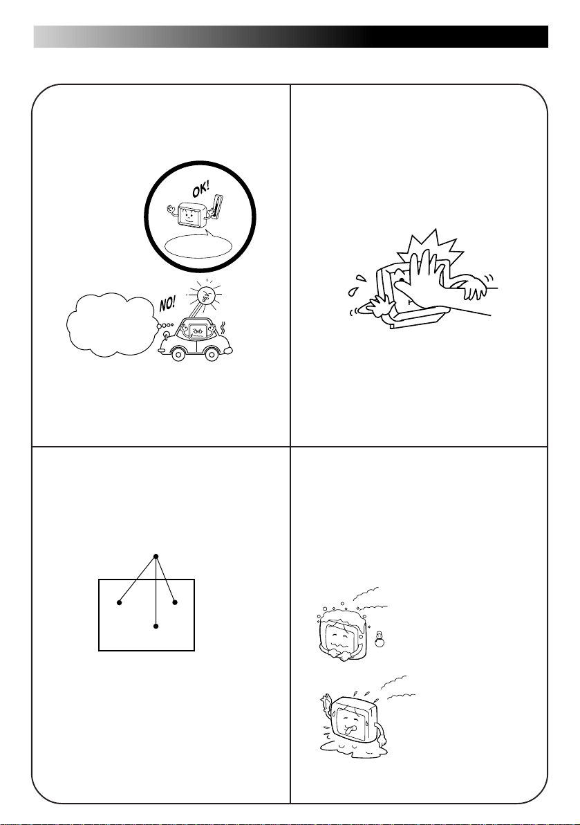
• Do not leave the liquid crystal panel surface
facing upwards on top of the dashboard.
(storage temperature range: –20 °C to +80 °C
(–4 °F to +176 °F) )
+80°C
–20
–20°C to +80°C
During the summer,
temperatures can
reach as high as
100 °C (212 °F).
When the liquid crystal panel reaches high
temperatures or low temperatures, chemical
changes occur within the liquid crystal panel
which may cause malfunctions.
• There are red spots, blue spots and green
spots on the panel surface. This is a characteristic of liquid crystal panels and is not a
problem.
Spots
• Do not strongly impact the liquid crystal panel.
• When the temperature is very cold or very hot,
the image may not appear clearly or may
move slowly.
Also, movement of the image may seem to be
out of sync or the image quality may decline in
such environments. Note that this is not a
malfunction or problem.
(usage temperature range: 0 °C to 40 °C (32
°F to 104 °F) )
0 °C (32 °F) or colder
The liquid crystal panel is built with very high
precision technology and has at least 99.99%
effective image pixels. Be aware that on
0.01% of the panel there may be missing
pixels or constantly light pixels.
40 °C (104 °F) or hotter
Page 5

Thank you for purchasing a JVC product. Please read all instructions carefully before operation,
to ensure your complete understanding and to obtain the best possible performance from the
unit.
Table of Contents
5
ENGLISH
Introduction to the Roles of the System Components ................6
How to Use the TV Tuner System
Watching Television ..................................................................1 1
Selecting a Channel..................................................................13
Controlling the Sound ...............................................................16
Adjusting Brightness .................................................................19
Adjusting the Sound..................................................................23
Adjusting the Image..................................................................25
Connecting to External Devices................................................27
How to Best Use the TV Tuner System
Troubleshooting ........................................................................28
When You Think There is a Problem ........................................29
Maintenance .............................................................................30
Specifications............................................................................31
ESPAÑOLFRANÇAIS
Page 6

6
Introduction to the Roles of the System
Components
Tuner unit
Terminal for connecting a mobile video
machine, video camera or other device
Not used at present
POWER
Terminal for connecting the power cord
Terminal for connecting the diversity antenna
DISPLAY UNIT
Terminal for connecting the display unit
AV INPUT 1
AV INPUT 2
L-AUDIO-R
VIDEO VIDEO
L-AUDIO-R
VIDEO
Terminal for connecting a mobile video
machine, video camera or other device
L-AUDIO-R
Terminal for connecting a 2nd
monitor or car stereo audio
output
AV
OUTPUT
Page 7
Introduction to the Roles of the System Components (continued)
KV-M65 display unit (sold separately)
7
POWER MODE MENU
Normally:
Used to turn the power
source ON and OFF
Changing the channel setting in the upward
or downward direction
When setting various menus:
Menu selection
When setting various adjustment modes:
Adjustment and switching
Used to display, select and determine the various
adjustments (screen, menu).
Used to display the configuration screen for changing
the input source and the various function menus.
To view TV broadcasts, it is necessary to connect the tuner unit with the JVC mobile color
monitor system KV-M65 (sold separately).
Dimmer sensor
This sensor automatically adjusts the screen brightness. (When
Auto Mode is set for the Dimmer Setting, the screen brightness is
Wireless remote controller light receiver
Used when the JVC mobile TV tuner
system KV-C1 is connected
automatically adjusted to one of 12 levels to suit the surrounding
brightness.)
KV-M65
MOBHE COLOR SYSTEMMOBHE COLOR SYSTEM
KV-M65
MOBILE COLOR MONITOR SYSTEM
ENGLISH
ESPAÑOLFRANÇAIS
STAND BY (R), ON (G)
When the power is off ... red
When the power is on ... green
Speaker
(on the back side)
Screw holes are provided for attaching the monitor
stand (on the bottom side).
(1/4 inch unify screw, maximum length of 4.5 mm)
Terminal for connecting
the cable from the
controller unit (on the
right side)
Page 8
8
MODE button
When pressed for less than 2 seconds: The input source can be changed.
8
RGB
VIDEO 1
VIDEO 2
Television channel number
When pressed for 2 seconds or longer: The setting screens for various functions can be
displayed.
[ SPEAKER MODE ]
SPEAKER MODE
VIDEO
M
ODE
DI
MM
ER MODE
END
M
OVE
SELECT
M
ENU
CURSOR
STANDARD
NAVIGATION
M
UTE
M
ENU
[ RGB MODE ]
NAVIGATION
NO CONNECT
M
ENU
[ DIMMER MODE ]
AUTO
M
ANUAL
M
ENU
16 to 18
ENTERSELECT
ENTERSELECT
19 to 22
ENTERSELECT
MENU button
When pressed for less than 2 seconds: The adjustment screen display can be selected.
(The following diagram shows an example for the Speaker Output Setting on All Modes
and the Dimmer Setting on Auto Mode.)
VOLUME
30
BRIGHT
-10
[CH MODE]
AUTOMANUAL
When pressed for 2 seconds or longer: The menus for image and sound can be displayed.
BLACK BASS
25, 26 23, 24
CONT TREBLE
COLOR BALANCE
TI NT SURROUND
END
M
OVE
M
ENU
CURSOR
SELECT
*
* Displayed only when VIDEO1
or VIDEO2 is selected.
When setting the menus: The Menu selection and adjustment can be decided.
Page 9

Introduction to the Roles of the System Components (continued)
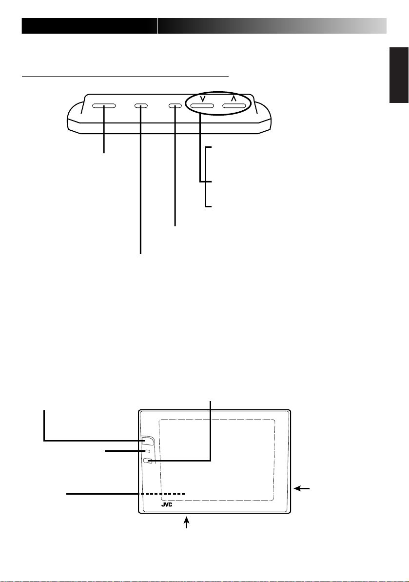
Wireless remote controller
9
Used to turn the power
source ON and OFF
Used to select the
television channels in order.
The Mode names are
displayed when the
television is not being used.
19 to 22
In the automatic mode:
Used to set to the best
visibility brightness level
for night time.
The numbers in the circles ( ) indicate the page on
which an explanation is provided in this manual.
Used to change the
input source.
RGBTV
POWER TV/VIDEO
VIDEO 1
CHANNEL
AUTO STORE
BRIGHT
VOLUME
VIDEO 2
14, 15
Used to pick up receivable
broadcast waves and store them
in memory.
Furthermore, the channels stored
in memory can be viewed in order.
RM-RK26
REMOTE CONTROL UNIT
Mode names are displayed when
the television is not being used.
16 to 18
ENGLISH
ESPAÑOLFRANÇAIS
In the manual mode:
Used to adjust the
screen brightness.
When STANDARD is selected in the
SPEAKER MODE configuration, this is
used to adjust the speaker sound
level.
When MUTE is selected in the
SPEAKER MODE, this is used to
adjust the sound output level of the
extension AV output terminal.
Page 10
10
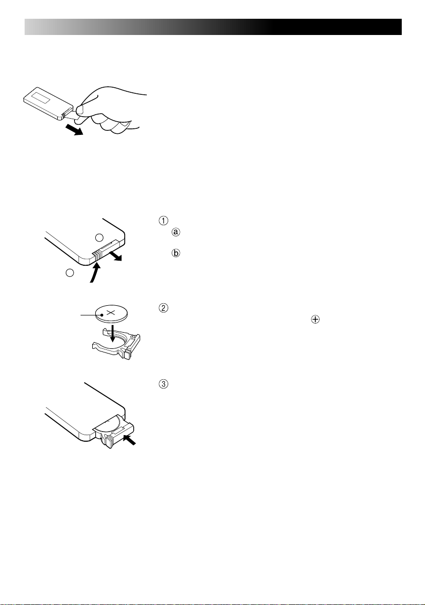
Before using the wireless remote controller
• A battery is already installed in the wireless remote controller. Remove the insulation film before using.
How to replace the battery
When it becomes necessary to bring the wireless remote controller close to the remote sensor
for it to work, the battery is running low. At this point, the battery should be replaced. (Battery life
is about 1 year with normal use.)
(back side)
a
Lithium coin
battery
(product number:
CR2025)
(back side)
Remove the battery case.
b
Push in the direction indicated by the arrow with your right
hand thumbnail.
Remove the battery case.
Replace the battery.
Put the battery in the case with the side facing upwards.
Return the battery case.
Re-insert the battery case pushing until you hear a clicking
sound.
WARNING
• Store the batteries in a place which children cannot reach.
* If a child somehow ingests the battery, immediately consult a doctor.
• Do not recharge, short, disassemble or heat the batteries or put
them in a flame.
Doing any of these things may cause the batteries to give off heat, crack or
start a fire.
• Do not mix the batteries with other metals.
Doing this may cause the batteries to give off heat, crack or start a fire.
• When throwing away or saving the batteries, wrap in tape and
insulate.
If this is not done, it may cause the batteries to give off heat, crack or start
a fire.
• Do not poke the batteries with a metal pin set or similar device.
Doing this may cause the batteries to give off heat, crack or start a fire.
Page 11

Watching Television
11
POWER
POWER MODE MENUPOWER MODE MENU
KV-M65 display unit
ACC
ON
POWER
or
POWER TV/VIDEO
CHANNEL
AUTO STORE
BRIGHT
VOLUME
Engage the parking brake and turn on the engine.
Note
• When the display unit is installed in a location which can be viewed
from the driver’s seat, the television image disappears while driving and only the sound can be heard.
• The best image is seen by looking straight on at the liquid crystal
panel.
Turn on the display unit power source.
Changes to the green light and a screen appears in the
mode before turning the power source off.
When pushed again, the power source is cut. (red light
turns on)
Request
• When AM radio broadcast is received while the display unit power
is left on, there may be interference with the car radio.
If this occurs, please turn the TV tuner system off.
ENGLISH
ESPAÑOLFRANÇAIS
8
RGB
VIDEO 1
Indicates that channel 8
is received
MODE
Changes with each push of the button
or
TV/VIDEO
VIDEO 2
Select the television screen from the input sources.
Note
• Refer to pages 13 to 18 for an explanation of how to select channels or control the sound.
Page 12

12
Watching Television (continued)
8
Disappears
after a short
time
or or
CHANNEL
AUTO STORE
Select the channel you would like to watch.
Note
• When the bright and dark portions of the screen are inverted or the
screen appears white:
Adjust the sound level of the car receiver connected to the
KV-C1 sound output.
Car receiver (with Line In terminal)
Refer to pages 25 and 26 and adjust the Black Level
Speakers
Page 13

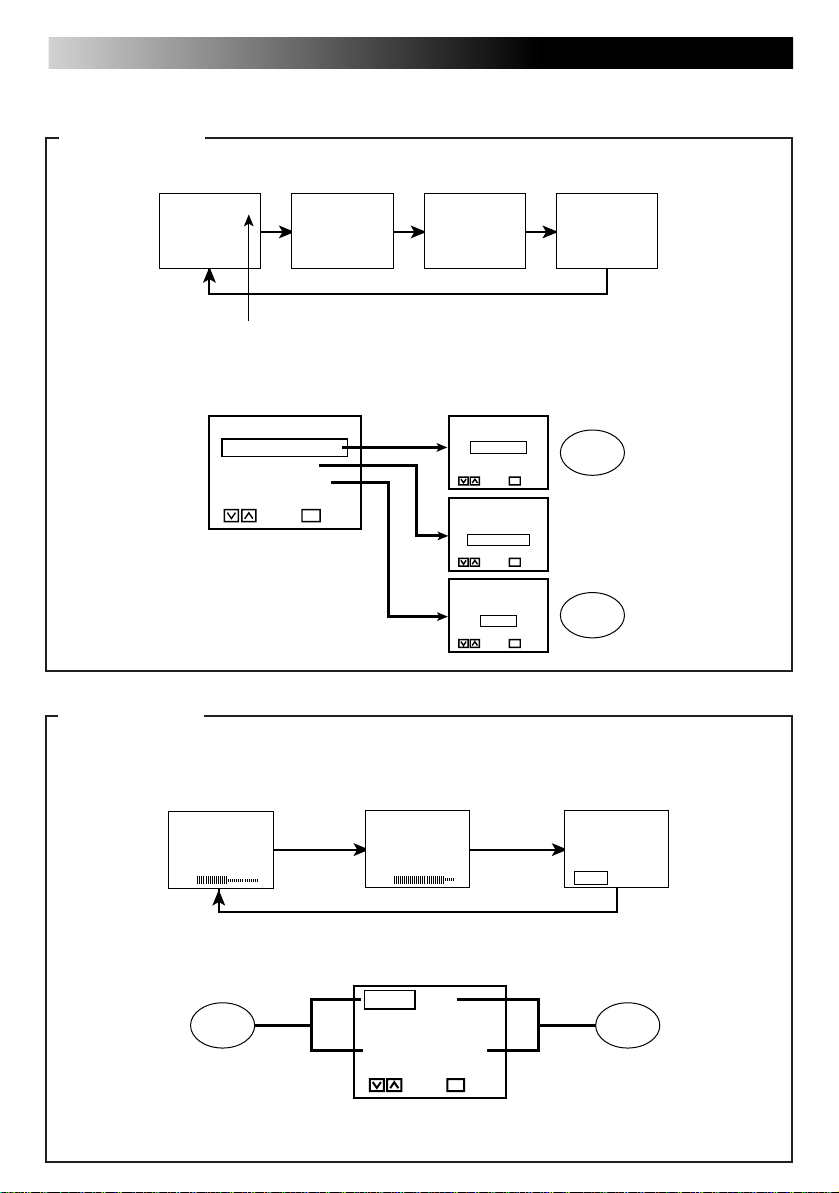
Selecting a Channel
13
For manual channel selection
(When the remote controller is used, channels can be directly selected using the “CHANNEL” button)
POWER MODE MENUPOWER MODE MENU
(changing the channel setting one channel at a time)
KV-M65 display unit
Press the MENU button 3 times quickly and the CH MODE
display is shown.
[CH MODE]
AUTOMANUAL
MENU
Select MANUAL.
[CH MODE]
AUTOMANUAL
ENGLISH
ESPAÑOLFRANÇAIS
Changes one
channel at a time
in the direction of
smaller numbers
Changes one
channel at a time
in the direction of
larger numbers
After the CH MODE display disappears, press the [ ] or
] button for less than 2 seconds and select the channel
[
you would like to watch.
Note
• When the [ ] or [ ] button is pressed for 2 seconds or longer:
The system will automatically select a channel and stop at a
channel where broadcast is being received.
Page 14

14
Selecting a Channel (continued)
For automatic storage channel selection
(used to view channels in the order in which they are stored in memory)
Operations on the display unit
POWER MODE MENUPOWER MODE MENU
Press the MENU button 3 times quickly and select the CH
[CH MODE]
AUTO
[CH MODE]
AUTO
MENU
M
M
ANUAL
ANUAL
MODE.
Select AUTO.
[AUTO SEARCH]
40CH
32
468
10 12
Shows the channel numbers
stored in memory
Channels stored in memory
are seen in order
Changes in the
direction of
smaller channel
numbers
Changes in the
direction of
larger channel
numbers
After the CH MODE display disappears, press the [ ] or
] button for 2 seconds or longer.
[
When automatic storage is finished, press the [ ] or [ ]
button for less than 2 seconds and select the channel you
would like to watch.
Note
• What is automatic storage (Auto Store)?
This function automatically picks up the broadcast waves which can be received in the region where the tuner system is being used and stores them
in memory. A memory of channels can be easily added when out on a drive
or other location. When the automatic storage function is used, the channels previously stored in the memory are lost.
• When automatic storage is finished:
The system returns to the channel being used prior to the automatic storage operation.
• When you are in a region where the electric waves are weak
It may not be possible to store channels in memory.
Page 15

Operating the wireless remote controller
15
[AUTO SEARCH]
40CH
32
468
10 12
Shows the channel
numbers contained
in memory.
AUTO STORE
Channels stored in memory
can be viewed in order.
Changes in the direction of
AUTO STORE
larger channel numbers
Changes in the direction of
smaller channel numbers
Shows how far
the channel
search has gone.
POWER TV/VIDEO
CHANNEL
AUTO STORE
BRIGHT
VOLUME
Press the AUTO STORE button for 2 seconds or longer.
When automatic storage is finished, press the [ ] or [ ]
button for less than 2 seconds and select the channel you
would like to watch.
ENGLISH
ESPAÑOLFRANÇAIS
Note
• There are times when channels which cannot be viewed are stored in memory. This is not a malfunction or problem.
• The channels stored in the memory by the Auto Store function cannot be erased.
• During Auto Store:
The voice muting circuit is activated and cuts unpleasant noise.
Page 16

16
Controlling the Sound
Selecting the volume of the built-in speakers
(The TV tuner system is set to the STANDARD at the time of shipment from the factory.)
POWER MODE MENUPOWER MODE MENU
SPEAKER MODE
VIDEO
M
ODE
DI
MM
ER MODE
END
M
OVE
SELECT
M
ENU
CURSOR
MODE
SPEAKER MODE
VIDEO
M
ODE
DI
MM
ER MODE
END
M
OVE
SELECT
M
ENU
CURSOR
[ SPEAKER MODE ]
STANDARD
NAVIGATION
M
UTE
ENTERSELECT
M
ENU
MENU
Press the MODE button for 2 seconds or longer.
Select the SPEAKER MODE.
Press the MENU button.
Note
• If no operations are performed for a period of 30 seconds after pressing the MODE button:
The Menu configuration screen automatically disappears.
Page 17

POWER MODE MENUPOWER MODE MENU
17
ENGLISH
ESPAÑOLFRANÇAIS
[ SPEAKER MODE ]
STANDARD
NAVIGATION
M
UTE
ENTERSELECT
M
ENU
VOLUME
30
MENU
VOLUME
30
Sound level (0-60 levels)
Select STANDARD.
After the SPEAKER MODE screen disappears (occurs after about 10 seconds), press the Menu button for less than
2 seconds and show the speaker volume level display.
Adjust the speaker volume level.
Note
• Relationship between the Speaker Mode setting and the built-in speaker volume
Speaker mode setting
STANDARD Television sound – Video 1 sound Video 2 sound
NAVIGATION Not used at present. Please select either STANDARD or MUTE.
MUTE There is no sound output from the speakers
• Speaker output is monaural sound. (It is not heard as stereo sound.)
Built-in speaker volume
Television RGB Video 1 Video 2
Page 18

18
Adjusting the volume output level of the AV output terminal
POWER MODE MENUPOWER MODE MENU
Perform steps 1 to 3 on page 16.
Press the MODE button for 2 seconds or longer.
Select the SPEAKER MODE setting using the [ ] and [ ]
buttons.
Press the MENU button.
[ SPEAKER MODE ]
STANDARD
NAVIGATION
M
UTE
M
ENU
SOUND LEVEL
40
MENU
SOUND LEVEL
40
Select MUTE.
Note
ENTERSELECT
• When MUTE is selected in advance:
With the remote controller, the volume level can be adjusted
directly using the volume button.
After the SPEAKER MODE setting screen disappears (occurs after about 10 seconds), press the MENU button for
less than 2 seconds and show the volume level display.
Adjust the volume output level of the AV output terminal.
Note
• When the SPEAKER MODE setting is on STANDARD:
The output level is fixed to the maximum of 60 and cannot be
adjusted. (See page 17 for more details.)
Page 19

Adjusting Brightness
For the automatic mode
(The TV tuner system is set to the Auto Mode at the time of shipment from the factory.)
Automatically adjusts the screen brightness to suit the brightness of the surrounding environment.
POWER MODE MENUPOWER MODE MENU
Press the MODE button for 2 seconds or longer.
SPEAKER MODE
VIDEO
M
DI
END
MM
ER MODE
M
OVE
CURSOR
MODE
ODE
SELECT
M
ENU
Note
• When END is selected, the system returns to the initial screen.
19
ENGLISH
ESPAÑOLFRANÇAIS
SPEAKER MODE
VIDEO
M
ODE
DI
MM
ER MODE
END
M
OVE
M
ENU
CURSOR
[ DIMMER MODE ]
AUTO
M
ANUAL
M
ENU
MENU
Select the DIMMER MODE.
SELECT
Press the MENU button.
ENTERSELECT
Page 20

20
[ DIMMER MODE ]
AUTO
M
ANUAL
DIMMER LEVEL
-55
MENU
POWER MODE MENUPOWER MODE MENU
Select AUTO.
Note
ENTERSELECT
M
ENU
• When the AUTO Mode is selected in advance:
With the wireless remote controller, it is possible to set this level
directly using the Brightness button without having to bring up
the DIMMER MODE screen.
After the DIMMER MODE screen disappears (occurs after about 10 seconds), press the Menu button for less than
2 seconds and show the automatic dimmer (darkness level)
display.
DIMMER LEVEL
-55
When set to 0, the brightness
does not change.
Use the [ ] or [ ] button to adjust brightness to the best
visibility at night.
Note
• When the adjustment is made to the best visibility at night, the
system automatically adjusts the level between the maximum
brightness and the brightness for the best visibility at night (minimum brightness).
(It is recommended that the setting be put between –40 and –60).
• When 0 is set, the value is fixed to the maximum level and the
brightness does not change.
Page 21

Adjusting Brightness
For the manual mode
The screen brightness can be adjusted manually.
POWER MODE MENUPOWER MODE MENU
Press the MODE button for 2 seconds or longer.
SPEAKER MODE
VIDEO
M
ODE
DI
MM
ER MODE
END
M
OVE
M
ENU
CURSOR
MODE
SPEAKER MODE
VIDEO
M
ODE
DI
MM
ER MODE
END
M
OVE
M
ENU
CURSOR
SELECT
SELECT
Note
• When END is selected, the system returns to the initial screen.
Select the DIMMER MODE.
21
ENGLISH
ESPAÑOLFRANÇAIS
[ DIMMER MODE ]
AUTO
M
ANUAL
ENTERSELECT
M
ENU
MENU
Press the MENU button.
Page 22

22
POWER MODE MENUPOWER MODE MENU
[ DIMMER MODE ]
AUTO
M
ANUAL
BRIGHT
-10
MENU
BRIGHT
-10
Select the MANUAL Mode.
Note
ENTERSELECT
M
ENU
• When the MANUAL Mode is selected in advance:
With the wireless remote controller, it is possible to set this level
directly using the Brightness button.
After the DIMMER MODE screen disappears (occurs after about 10 seconds), press the MENU button for less
than 2 seconds and show the brightness display.
Use the [ ] or [ ] button to adjust the brightness to your
preferred level.
Page 23

Adjusting the Sound
POWER MODE MENUPOWER MODE MENU
23
ENGLISH
ESPAÑOLFRANÇAIS
Example: Adjusting the bass level
BLACK BASS
CONT TREBLE
COLOR BALANCE
TI NT SURROUND
END
M
OVE
SELECT
M
ENU
CURSOR
MENU
BLACK BASS
CONT TREBLE
COLOR BALANCE
TI NT SURROUND
END
M
OVE
SELECT
M
ENU
CURSOR
BASS
0
MENU
BASS
+15
Press the MENU button for 2 seconds or longer.
Select BASS.
Press the MENU button.
Adjust the BASS level.
Note
• After 10 seconds passes:
The BASS Adjustment screen automatically disappears.
Note
• When END is selected, the system returns to the initial screen.
• Bass, Treble, Balance and Surround do not change in the case of a built-in speaker.
Page 24

24
BASS
+15
TREBLE
+15
BALANCE
+15
SURROUND ON
ENTERSELECT
M
ENU
Adjustment points (The bass, treble and balance can be adjusted from the setting screens)
BASS
BASS
-15
Bass is reduced. Bass is increased.
TREBLE
-15
Treble is reduced. Treble is increased.
(level of low tones)
TREBLE
(level of high tones)
BALANCE
-15
Sound output of the
right side is lowered.
SURROUND OFF
M
ENU
BALANCE
Balances the sound
output between the left
and right speakers
Sound output of the
left side is lowered.
SURROUND
ENTERSELECT
The feature gives a 3D
effect to the sound when
VIDEO1 or VIDEO2 is in
stereo format.
Page 25

Adjusting the Image
POWER MODE MENUPOWER MODE MENU
25
ENGLISH
ESPAÑOL
Example: Adjusting the black level
BLACK BASS
CONT TREBLE
COLOR BALANCE
TI NT SURROUND
END
M
OVE
SELECT
M
ENU
CURSOR
MENU
BLACK BASS
CONT TREBLE
COLOR BALANCE
TI NT SURROUND
END
M
OVE
SELECT
M
ENU
CURSOR
BLACK
0
MENU
Press the MENU button for 2 seconds or longer.
Note
• When END is selected, the system returns to the initial screen.
• For an RGB screen, only the Black level and Contrast are shown.
(Not used at present.)
• If no operations are performed for a period of 30 seconds after
pressing the MENU button
The Menu configuration screen automatically disappears.
Select BLACK.
Press the MENU button.
Adjust the Black level.
FRANÇAIS
BLACK
+15
Note
• After 10 seconds passes
The Black level adjustment screen automatically disappears.
Page 26

26
BLACK
+15
CONT
+15
COLOR
+15
TINT
+15
Adjustment points (Image features can be adjusted from the various setting screens)
BLACK LEVEL
BLACK
-15
Adjust the Black Level when there is an inversion of the black and white on the
screen or the screen appears too white due to an imbalance in the relationship
between the installation position of the monitor and eye level.
When the Black Level is
on the negative [–] side.
Makes the black portions of the
screen easier to see (Night
scenes, black hair, etc.)
When the Black Level is
on the positive [+] side.
CONTRAST
Normally set in the middle.
CONT
-15
Move to the right for more
contrast.
COLOR
COLOR
-15
Colors are less vivid. Colors are more vivid.
Setting to slightly
thicker colors
TINT
TINT
-15
Skin color has a reddish-purplish tint.
Setting for attractive
skin color
Skin color has a
greenish tint.
Page 27

Connecting to External Devices
27
Connection example 1
Mobile video machine or video camera (AV input 1) and car stereo (Audio output)
To car stereo
AV input 1
Tuner unit
AV INPUT 1
DISPLAY UNIT
POWER
AV INPUT 2
L-AUDIO-R
VIDEO
L-AUDIO-R L-AUDIO-R
VIDEO
VIDEO
AV
OUTPUT
Audio output
(video terminal
not connected)
Connection example 2
Mobile video machine (AV input 1) and 2nd monitor (AV output)
To 2nd monitor
ENGLISH
ESPAÑOL
FRANÇAIS
AV input 1
Tuner unit
POWER
L-AUDIO-R
VIDEO VIDEO
L-AUDIO-R L-AUDIO-R
VIDEO
AV INPUT 2
AV
OUTPUT
AV output
AV INPUT 1
DISPLAY UNIT
Note
• Refer to the installation manual for an explanation of how to make these connections.
• Since the connection cord varies depending on what external devices are connected, refer to the
video equipment manual as well.
• For connection of a mobile video machine or video camera:
When howling (a “pi” sound) occurs, take one of the following steps.
· Lower the volume on the TV tuner system
· Use earphones (when the camera has an earphone jack)
· Keep the tuner system and the camera microphone apart.
Page 28
28
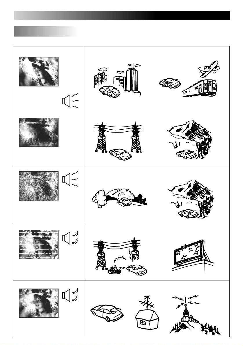
Troubleshooting
In the following environments, the image quality may be impaired.
Movement
Interference
occurs
Doubling and tripling of
images (ghosts)
Interference
occurs
Image quality gradually
worsens and color instability
(displayed and then disappear)
Between buildings A plane flies overhead
Near electricity
transmission wires
Mountain or tree shadow Distance from the broadcast
A train passes close by
Mountain shadow
station
Normal
sound
Spots appear on the screen
Normal
sound
Color patterns appear on the
screen; colors are lost
Near an automobile, motor bike, high-voltage wires or a neon sign
Near the transmission antenna of a radio station or an amateur
wireless station,or when a wireless device is being used in a
vehicle
Page 29

When You Think There is a Problem
Please check the following items one more time.
29
When this occurs
There are red, blue and
green spots on the
screen.
There is sound output,
but no video output
(only the channel
number is shown).
There is no television
image and also no
sound.
The wireless remote
controller does not
work.
REMOTE CONTROL UNITREMOTE CONTROL UNIT
REMOTE CONTROL UNIT
RM-RK21
RM-RK21
Check these points
This is a characteristic of liquid crystal panels and is not a
problem.
(The liquid crystal panel is built with very
high precision technology and has at least
99.99% effective image pixels. Be aware
that on 0.01% of the panel there may be
missing pixels or constantly light pixels.)
• Is the parking brake connection wire (gray color) connected?
• Was the parking brake lever pulled?
[Mode Button]
• Is the Mode button set to video input 1 screen or video input 2
screen or to RGB?
• Has the battery run out?
• Is a strong light shining on the remote controller receiver?
• Is the remote controller for this tuner system being used?
Reference
page
–
Refer to
the
installation
manual
11
10
ENGLISH
ESPAÑOL
FRANÇAIS
There is no sound from
the speakers.
The screen is dark.
The screen black and
white portions are
inverted.
The screen is too white.
The color is thin.
The tint is off.
[Speaker Volume Adjustment]
Is the volume on the lowest level?
[Speaker Output Setting]
Is the setting on No Output?
[Brightness, Black Level and Contrast]
Are the settings properly adjusted?
[Color and Tint]
Are the settings properly adjusted?
16, 17
18
19 to 22
25, 26
25, 26
Page 30

30
Alcohol
Benzine
Thinner
Adhesive
tape
Pesticide
Wax
Tape
Maintenance
To prevent damage to the system exterior
Do not apply pesticides, benzine, thinner or other
volatile substances to the unit.
The cabinet surface primarily consists of plastic materials.
Do not wipe with benzine, thinner or similar substances because this will results in discoloration or
removal of the paint.
When a cloth with a cleansing chemical is used,
follow the caution points.
Do not leave the unit in contact with rubber or vinyl
products for long periods of time.
Do not use cleansers which have polishing granules because this could damage the surface of the
unit.
Clean dirt by wiping lightly with a soft cloth
When the unit is very dirty, wipe with a well-wrung cloth
dipped in a kitchen cleanser (neutral) thinned by water and
then go over the same surface with a dry cloth.
(Since there is the possibility of water drops getting inside
of the unit, do not directly apply cleanser to the surface.)
Wring well Wipe lightly
Go over the same surface
with a dry cloth
Kitchen cleanser thinned by water
Request
If water drops or similar wet substances get inside of the monitor via the liquid crystal panel surface, it may cause a malfunction.
Page 31

Specifications
31
Product type Mobile TV tuner system
Power source voltage DC 14.4V (can be used within the range of 11V to 16V);
negative ground only
Reception channels VHF channels 2 to 12, UHF channels 13 to 69
Usage temperature range 0°C to +40°C (32°F to 104°F)
Overall system
Storage temperature range –20°C to +80°C (-4°F to +176°F)
Connection terminals • Power, ground, parking brake, remote output connection
terminals (10 pin connector)
• Diversity antenna connection terminal (75ohm/M3 mini
jack)
• Display unit connection terminal (13-pin DIN connector)
• AV input 1 and input 2 terminals
Video 1Vp-p(75Ω/RCA pin)
Audio 0.5Vrms (RCA pin)
Tuner unit
Dimensions Width 19.6 cm (7-3/4”), depth 14.2 cm (5-5/8”),
Mass 930 g (2.1 lbs)
Power source DC 3V (lithium coin battery)
Remote controller Within a range of about 3 meters (distance from the front of
operation distance the display)
Dimensions Width 4.0 cm (1-5/8”), length 8.6 cm (3-7/16”),
controller
Wireless remote
Mass 16 g (0.04 lbs) (without the battery)
Output impedance 75Ω x 4 (with mini plug)
Cable length 4 m (13.3 ft)
Dimensions About width 46 cm (18-1/8”), height 46 cm (18-1/8”),
Mass (each unit) About 165 g (0.37 lbs)
Diversity antenna
• AV output terminal Video 1Vp-p(75Ω/RCA pin)
Audio 0 to 0.5Vrms(RCA pin)
(consecutive change supported by
sound level adjustment)
height 3.8 cm (1-1/2”)
height 0.7 cm (5/16”)
depth 1.8 cm (3/4”) (without the cable)
(including the cable)
ENGLISH
ESPAÑOL
FRANÇAIS
Page 32

VICTOR COMPANY OF JAPAN, LIMITED
KV-C1
EN, SP, FR.
Printed in Japan
0498MNMUBNMTS
 Loading...