

Page 1
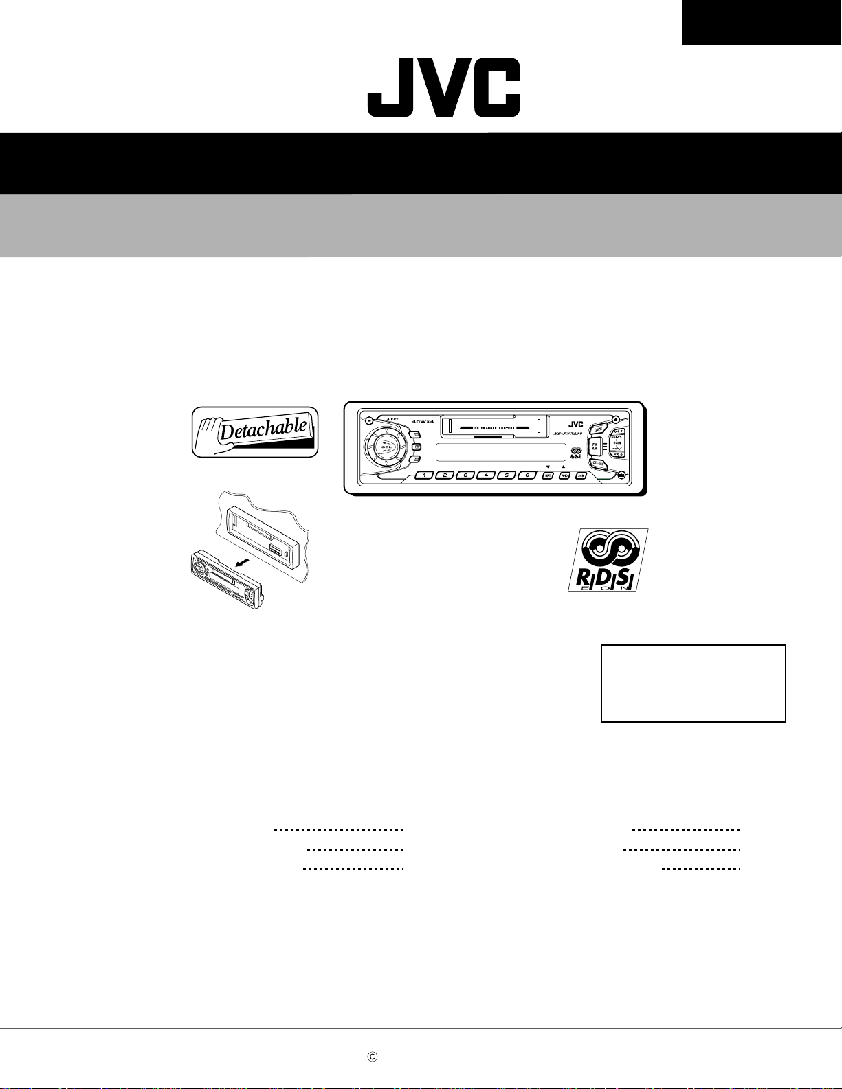
SERVICE MANUAL
CASSETTE RECEIVER
KS-FX722R
KS-FX722R
Contents
DISPDISP
TP TP
RDSRDS
PTYPTY
8 9 10 11 127
DAB
MO
Area Suffix
E ---- Continental Europe
Safety precaution
Location of main parts
Disassembly method
1-2
1-3
1-4
COPYRIGHT 2001 VICTOR COMPANY OF JAPAN, LTD.
Adjustment method
Wiring connections
Description of major ICs
1-10
1-14
1-15
No.49591
Jan. 2001
Page 2
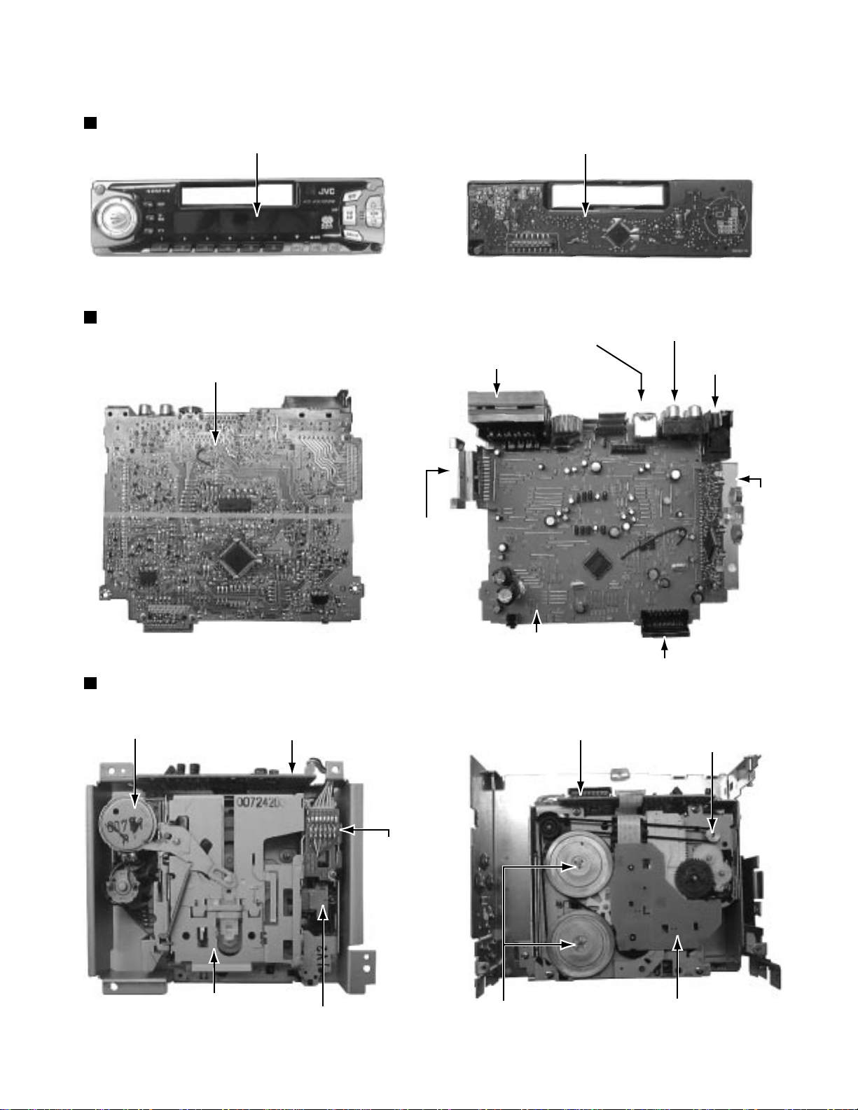
Location of main parts
Control unit
Display
KS-FX722R
Control unit
Main unit
Main board
Cassette mechanism
Power IC
Changer control
connector
I/O connector
Main board assembly
RCA jack
Antenna
jack
Tuner
pack
Connector to controller
C.motor assembly
Mechanism control board assembly
Cassette housing
Head
Head relay board
Mechanism control board assembly
Flywheel assembly
Capstan motor assembly
Reel board
1-3
Page 3
KS-FX722R
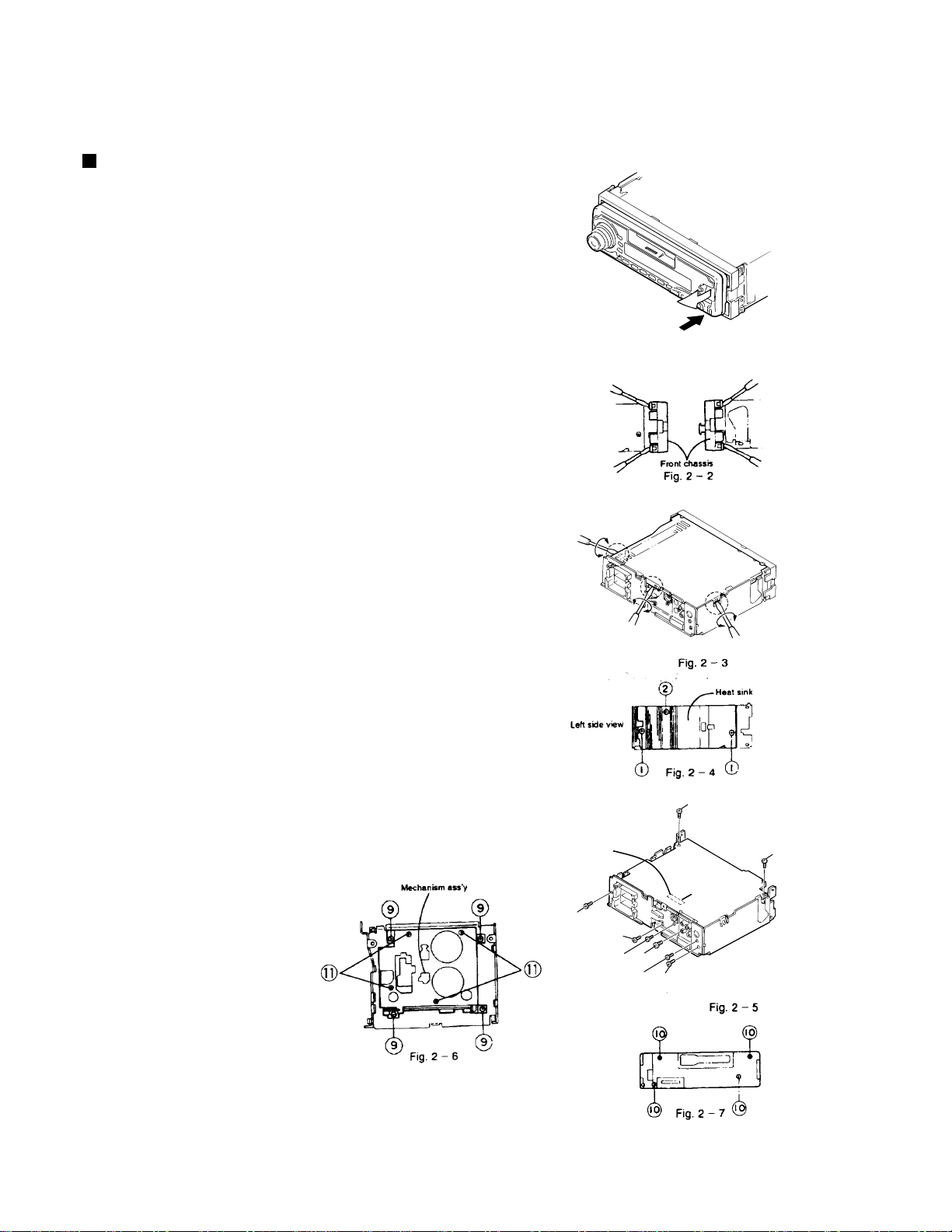
Disassembly method
Removal of main parts
Enclosuer section
(1) Detaching the front panel unit (see Fig.2-1)
Side the Release slide knob in the direction of arrow
to detach the front panel unit.
(2) Removing the front chassis(see Fig.2-2)
Disengage the four tabs in the right and left sides of unit
and pull the front chassis forward to remove it.
(3) Removing the bottom cover(see Fig.2-3.2-4)
1.Remove one screw 2 retaining the IC to the heat sink.
2.Remove two screws 1 to remove the heat sink.
3.Turn the upside down, then insert and turn the
screwdriver to remove the bottom cover and
protect sheet.
(4) Removing the main P.C.B.assembly
(with rear panel) (see Fig.2-5)
1.Remove two screws 4 retaining the rear panel to the chassis.
2.Remove two screws 3 retaining the amp. P.C.B. assembly.
3.Lift up the main P.C.B. assembly to remove it. At this
time, remove the connector CP501 connecting the
main P.C.B assembly and mechanism assembly.
(5)Removing the rear panel(see Fig.2-5)
Remove six screws retaining the jacks or the like.
Remove one screw 5 to the IC bracket.
Remove one screw 6 to remove the line-out jack.
Remove one screw 7 to remove the antenna jack.
Remove one screw 8 to remove the changer
controller jack. (except KS-F530R)
Top side
Detach it
Press the Control Panel
Release button to detach the control panel.
Fig. 2 - 1
Bottom Cover
1-4
(6)Mechanism assembly(see Fig.2-6)
1.Remove four mechanism mouting screws 9 retaining
the mechanism assembly.
2.Remove four screws B retaining the cover.
3.Remove one screw which is the fixation of TOP COVER and
the substrate.
(7)Front panel unit(see Fig.7)
Remove four screws A retaining
the rear cover.
Connection to the mechanism
connector position
4
5
8
6
7
3
3
Main Board
CP501
4
Page 4
KS-FX722R
Adjustment method
Test instruments reqired f
1. Digital osclloscope(100MHz)
2. Frequency Counter meter
3. Electric voltmeter
4. Wow & flutter meter
5. T est T apes
MC-109C
VT724.......................
VT739............For playback frequency measurement
VT712....For wow flutter & tape speed measurement
VT703..................... For head azimuth measurement
6. T orque gauge .................... Cassette type for CTG-N
...................
for TAPA CURL confirmation
(without Padd type)
for DOLBY level measurement
or adjustment
(mechanism adjustment)
Measuring conditions(Amplifier section)
Power supply voltage.............. DC14.4V (10.5 - 16V)
Load impedance ........... 4 (2Speakers connection)
Line out............................................................ 20k
Standar
Balance and Bass,Treble volume .Fader
:Center(Indication"0")
Loudness,Dolby NR,Sound,Cruise:Off
Volume position is about 2V at speaker output with
following conditions.Playback the test tape VT721.
AM mode 999kHz/62dB,INT/400Hz,30%
FM mono mode 97.5MHz/66dB,INT/400Hz,22.5kHz
FM stereo mode 1kHz,67.5kHz dev . pilot7.5kHz dev.
Output level 0dB(1 V,50 /open terminal)
d volume position
modulation signal on recieving.
deviation pilot off mono
1-10
Page 5

KS-FX722R
Main board
Information for using a car audio service jig
1. We're advancing efforts to make our extension cords common for all car audio products.
Please use this type of extension cord as follows.
2. As a U-shape type top cover is employed, this type of extension cord is needed to check operation of the
mechanism assembly after disassembly.
3. Extension cord : EXTKSRT002-18P ( 18 pin extension cord ) For connection between mechanism assembly
and main board assembly .
Check for mechanism driving section such as motor ,etc..
Disassembly method
1. Remove the bottom cover.
2. Remove the front panel assembly.
3. Remove the top cover .
4. Install the front panel.
5. Confirm that current is being carried by connecting
an extension cord jig.
Note
Available to connect to the CP701 connector when installing the front panel.
Extension cord
EXTKSRT002-18P
Cassette mechanism
to Cassette mechanism
EXTKSRT002-18P
Main board
Front panel assembly
to Main board
1-12
Page 6

KS-FX722R
Wiring connections
Mecha control board
CN403
Reel board
Flat cablle
CN402
Head relay board
CN401
0
9
0
9
9
Playback head
4 20
13
1 3 4
20 9
CP501
Reel motor
Changer connector
0
1
2
3
Sub motor
1
3
1-14
Main board
Control board
CJ701
CP701
Color codes are shown below.
1
2
3
4
5
6
7
8
9
0
D
C
Brown
Red
Orange
Yellow
Green
Blue
Violet
Gray
White
Black
Pink
Light Blue
Page 7
Description of major ICs
UPD178018AGC584(IC701) : System controller micon
1.Terminal Layout
24 – 1
25
80
KS-FX722R
–
40
–
65
41 – 64
2.Description
Pin
Symbol I/O Function
No.
1 KEY0 I Key input 0
2 KEY1 I Key input 1
3 KEY2 I Key input 2
4 LEVEL I Level meter input
5 SM I Signal meter input
6 SQ I Signal quality input
7 LCDCE O Chip enable output to LCD driver
8 LCDDA O Data output to LCD driver
9 LCDSCK O Clock output to LCD driver
10 BUSI/O O J-BUS I/O switch output
11 UNLOCK O PLL unlock output L:unlock H:lock
12 BUSSI I J-BUS data input
13 BUSSO O J-BUS data output
14 BUSSCK O J-BUS clock output
15 - 20 NC - Non connect
21 GNDPORT - GND for port
22 VDDPORT - VDD for port
23 NC - Non connect
24 AFCK O AF check output L:AF check
25 MONO O Monaural ON/OFF output H:Monaural ON
26 FM/AM O Output for FM power supply H:FM Mode
27 SEEK/STOP O Auto seek/Stop output H:Aut seek L:Stop
28 NC I Non connect
29 IFC I FM middle frequency counter input
30 VDDPLL - VDD for PLL
31 OSC I FM/AM oscillation input
32 NC - Non connect
33 GNDPLL - GND for PLL
34 EO0 O Error out output from change pump
35 EO1 O Error out output from change pump
36 IC - Connect to Ground
37 SD/ST I Seek/Stop port H:SD input
Seek/Stop port L:Stereo input
38 STAGE I H:It is CD mode and there is REPEAT
L:Does not exist
39 NC - Non connect
40 MOTOR O Main motor output H:At rotation
41 FF/REW O MS IC sensitivity switch output L:FF/REW
42 F/R O FWD/REV change input H:FWD L:REV
Pin
Symbol I/O Function
No.
43 DOLBY O Dolby NR output H:Dolby NR ON
44 MS IN I Between tunes signal input
H:Between tunes
45 I2CSCK I/O E-VOL IC control clock I/O
46 I2CDAO O E-VOL IC control data output
47 I2CDAI I E-VOL IC control data input
48 REEL I Reel rotation detect signal input
49 SUBMO- O Sub motor output 50 SUBMO+ O Sub motor output +
51 MODE I Mode position detection input H:Non-mode
L:Mode position
52 TAPEIN I Cassette in detect input H:IN L:OUT
53 STBY I Standby detect input H:Eject side
L:Operation side
53 T-END I Tape end detect input 200ms L:tape end
54-59 NC - Non connect
60 MUTE O L:Mute ON H:Mute OFF
61 POWER O Power supply output H:power ON
62 TEL-MUTE I TEL-MUTE input
63, 64 NC - Non connect
65 ENC1 I Encoder signal input
66 ENC2 I Encoder signal input
67 ON I H:Operation mode L:Power save mode
68 STOP I Stop mode input
69 RDSCK I RDS clock input
70 RDSDA I RDS data input
71 REMOCON I Remocon signal input (Not used)
72 DETACH I Detach input It is "L" of 200ms or more and
an operation mode H:power save mode
73 JBUS INT I J-BUS Interruption input
74 REGCPU - Connects GND through the capacitor
of 0.1 F
75 GND - To ground
76 X2 - Crystal oscillator connection for system
77 X1 - clock oscillation
78 REGOSC - Connects GND through the capacitor
of 0.1 F
79 VDD - Power supply
80 NC - Non connect
1-15
Page 8
KS-FX722R
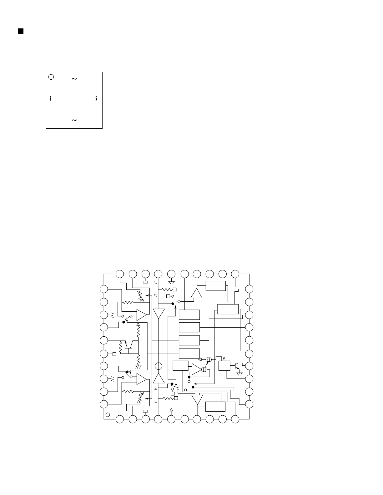
CXA2559Q(IC401):Playback equalizer amplifier with music sensor
1.Pin layout
40 31
1
30
10
11 20
2.Blockdiagram
PBFB2
PBRIN2
PNGND
PNFIN2
VCT
PBREF
PBFIN1
PBGND
PBRIN1
PBFB1
21
31
32
33
34
35
36
37
38
39
40
45k
PBTC2
30
7k/12k
300k
F2
30k
30k
F1
300k
7k/12k
PBOUT2
OUTREF2
29
28
-
+
+
-
TAPEIN2
27
100k
70 /12070 /120
T2
X1
X1
T1
100k
GND
26
FWD/RVS
LPF
DIREF
25
BIAS
MUTE
TAPE EQ
Vcc
+
-
F3
LINEOUT2NCNC
24
23
24dB
-
+
MS MODE
DET
+
-
24dB
22
MSSW
21
MS ON/
OFF
20
19
18
17
16
15
14
13
12
11
MSMODE
DRSW
TAPESW
MUTESW
NC
NC
MSOUT
MSTC
G1FB
G2FB
1-16
1
2
PBTC1
PBOUT1
3
4
TAPEIN1
OUTREF1
5
NC
6
NC
7
8
NC
LINEOUT1
9
NC
10
MSLPF
Page 9

KS-FX722R
3.Pin function
Pin No.
10
11
12
13
14
15
16
17
18
19
20
21
22
23
24
25
26
27
28
29
30
31
32
33
34
35
36
37
38
39
40
1
2
3
4
5
6
7
8
9
Symbol
PBTC1
PBOUT1
OUTREF1
TAPEIN1
Vcc
NC
LINEOUT1
NC
NC
MSLPF
G2FB
GI1FB
MSTC
MSOUT
NC
NC
MUTESW
TAPESW
DRSW
MSMODE
MSSW
NC
NC
LINEOUT2
DIREF
GND
TAPEIN2
OUTREF2
PBOUT2
PBTC2
PBFB2
PNRIN2
PBGND
PBFIN2
VCT
PBREF
PBFIN1
PBGND
PBRIN1
PBFB1
I/O
Function
-
Terminal of capacity of reproduction equalizer reproduction
O
Equalizer output terminal
O
Output standard terminal
I
Tape input terminal
-
Power supply terminal
-
Non connection
O
Line-out output terminal
-
Non connection
-
Non connection
-
Detection LPF terminal between tunes
-
Detection level set terminal between tunes
-
Detection level set terminal between tunes
-
Time constant connection terminal for the detection between tunes
O
Detection output terminal between tunes
-
Non connection
-
Non connection
I
Mute function control terminal
I
Reproduction equalizer control terminal
I
Head change control terminal
I
Detection mode control terminal between tunes
Detection function control terminal between tunes
I
Non connection
Non connection
Line-out output terminal
O
Resistance connection terminal for standard current setting
Earth terminal
Tape input terminal
I
Output standard terminal
O
Reproduction equalizer output terminal
O
Terminal of capacity of reproduction equalizer
Reproduction equalizer return terminal
I
Reproduction equalizer input terminal
I
Reproduction equalizer system earth terminal
Reproduction equalizer input terminal
I
Middle point terminal
O
Reproduction equalizer standard terminal
O
Reproduction equalizer input terminal
I
Reproduction equalizer system earth terminal
Reproduction equalizer input terminal
I
Reproduction equalizer return terminal
I
CXA2559Q 2/2
1-17
Page 10

KS-FX722R
HA13158A (IC941) : Power amp
1. Pin layout
1 ~ 23
2. Block diagram
INVCC
IN1
2
STBY
1
14 18 6
PVCC1PVCC2
INPUTBUFFER1
AMP1
+
3
4
-
5
IN2
IN3
IN4
11
13
23
10
MUTE
INPUTBUFFER2
INPUTBUFFER3
INPUTBUFFER4
PROTECTOR (ASO
SURGE, TSD)
12 22
AMP2
AMP3
AMP4
TAB
7
+
8
-
9
15
+
16
-
17
19
+
20
-
21
1-18
Page 11

KS-FX722R
LC75823E (IC651) : LCD Driver
1. Pin Layout & Symbol
S1
S2
S3
S4
S5
S6
S7
S8
S9
S10
S11
S12
S13
S14
S15
S16
2. Pin Function
DICLCE
64 63 62 61 60 59 58 57 56 55 54 53 52 51 50 49
1
2
3
4
5
6
7
8
9
10
11
12
13
14
15
16
17 18 19 20 21 22 23 24 25 26 27 28 29 30 31 32
S17
S18
S19
OSC
S20
Vss
S21
VDD2
VDD1
S22
S23
INH
S24
VDD
S25
COM3
COM2
S26
S27
COM1
S52
S28
S29
S51
S30
S50
S31
S49
48
47
46
45
44
43
42
41
40
39
38
37
36
35
34
33
S32
S48
S47
S46
S45
S44
S43
S42
S41
S40
S39
S38
S37
S36
S35
S34
S33
Pin No.
1 to 52
53 to 55
56
57
58
59
60
61
62
63
Symbol
S1 to S52
COM1 to COM3
VDD
INH
VDDD1
VDD2
Vss
OSC
CE
CL
I/O
O
Segment output pins used to display data transferred
Function
by serial data input.
O
Common driver output pins. The frame frequency is given
by : t0=(fosc/384)Hz.
--
Power supply connection. Provide a voltage of between
4.5 and 6.0V.
I
Display turning off input pin.
INT="L" (Vss) ----- off (S1 to S52, COM1 to COM3="L"
INT="H" (VDD)----- on
Serial data can be transferred in display off mode.
I
Used for applying the LCD drive 2/3 bias voltage
externally.
Must be connected to VDD2 when a 1/2 bias drive scheme
is used.
I
Used for applying the LCD drive 1/3 bias voltage
externally.
Must be connected to VDD1 when a 1/2 bias drive scheme
is used.
--
Power supply connection. Connect to GND.
I/O
Oscillator connection.
An oscillator circuit is formed by connecting an external
resistor and capacitor at this pin.
Serial data CE : Chip enable
interface connection
I
to the controller. CL : Sync clock
1-22
64
DI
DI : Transfer data
Page 12

1
2
3
4
5
KS-FX722R
Block diagram
SUB
MOTOR
ABC
TO CD CHANGER
J751 CP961
SCK
SI/SO
IC751
CHANGER CONTROL
HD74HC126FP-X
JBUS SI
JBUS SO
JBUS I/O
J1
AM
FM
AM/FM TUNER P ACK
QAU0156-001
Tuner.Power AMP.Changer/System Controller
JBUS SCK
TU1
CD RCH
CD LCH
SEEK/STOP
SD/ST
SMETER
TO SPEAKER
CONNECTOR TO REAR LINE OUT
L/R F
L/R R
IC941
POWER AMP.
HA13158A
OUT LR
OUT RR
OUT LF
OUT RF
IC911
E.VOLUME
TEA6320T-X
TUNER L/R
TAPE L/R
IC701
SYSTEM CONTROL MICON
UPD178018AGC584
LRO
RRO
SWITCH
TAPE END.STANDBY
J931
F/R
MODE
STANDBY
FF/REW
MOTOR
SUBMO
TAPE IN
DOLBY
MS
REEL
KEY 0 – 2
CP501
CJ701
CJ403
CJ401
CP701
MAIN
MOTOR
MOTOR
TAPE IN
MODE
STANDBY
PHOTO
REEL
DOLBY
F/R
MS OUT
LCH
RCH
FF/REW
CE
CLOCK
DATA
HEAD
CJ402
LCH
RCH
IC401
PB EQ
CXA2559Q
IC402
DC MOTOR DRIVER
SUBMO+
SUBMO-
LB1641
MECHANISM CONTROL
LCD1
QLD0158-001
S3 – S52
COM0 – COM3
IC651
LCD DRIVER
LC75823E
KEY
– S619
S601
LCD DRIVER/KEY SWITCH CIRCUT
METAL
2-1
Page 13

Standard schematic diagrams
Receiver & System control section
TU1
QAU0222-001
IC941
KS-FX722R
HA13158A
1k
R236
D931
1SS355-X
D933
1SS355-X
D977
1SS355-X
Q979
DTA114EKA-X
D966
CRS03-W
18k
R980
D932
R978
6.8k
C977
1K
R234
100/6.3
C967
R141
15k
R142
15k
15K
R241
15K
R242
1K
R134
R132
2.2k
R232
2.2k
MA152WA-X
1SS355-X
1/50
39k
R144
39k
R244
470
R977
Q978
DTC114EKA-X
D982
C966
100/16
39k
R143
39k
R243
R235
R135
R981
1k
C963
470p
470p
10/16
C945
R131
2.2K
2SC2412K/R/-X
10/16
0.1
C944
R133
100
100
R233
Q132
2.2K
C932
0.1
J931
QNN0175-001
2SC2412K/R/-X
0.1
C978
10/10
R961
100
R960
100
C933
C144
C143
470p
470p
C243
C244
100
100
Q131
2SC2412K/R/-X
Q231
2SC2412K/R/-X
10K
4.7K
0.1/50
R963 R962
R941
47k
Q232
R231
C962
0.047
C970
2.2
D965
CRS01-W
C901
FM Radio signal / Radio main signal
AM Radio signal
CD signal
Tape PB / Main signal
Parts are safety assurance parts.
C942
0.1
C969
C961
D961
L961
QQR0703-001
0.1
C943
0.047
2200/16
1N5401-TU-15
0.1
C941
C979
10/16
QNZ0112-001
CP961
J1
0.056
C6
0.22
C711
J751
QNZ0095-001
QNB0100-001
Q11
1k
R12
2SC2412K/R/-X
C1
0.1/50
4.7k
R3
D951
1SS133-T2
12
R30
C701
27P
C702
27P
C709
C151
1/50
Q3
C25
0.1
Q4
DTA114EKA-X
0.01
C302
C301
330p
R708
100k
R713
10k
R710
2.7K
R707
47K
C703
X701
C704
QAX0406-001Z
100/6.3
0.1
L1
4.7u
D1
D2
1SS119-041
1SS119-041
C18
C17
C20
0.001
150P
1k
1k
2.2/50
Q12
R14
33
C21
2SC2412K/R/-X
DTC114EKA-X
CH.R
CH.L
0.22/50
2SA1037AK/RS/-X
R8
4.7k 47k
1.5k
R29
Q13
Q1
DTC114EKA-X
100/16
C9
R749
10K
C766
47/16
C767
0.01
C765
47p
QAX0263-001Z
C764
X761
82p
C712
0.1
R756
100k
R757
100k
R758
100
R759
330k
R24
R25
R26
10k
R27
1k
2SA1037AK/RS/-X
47p
C30
Q6
R7
2.2k
R761
R762
2.2k
R982
10K
10k
R755
IC751
HD74HC126FP-X
0
R32
0.047
IC761
SAA6579T-X
R983
10K
10p
C29
C24
D3
1SS355-X
R754
3.3k
100
R5
C751
Q5
0.1
DTC114EKA-X
Q2
R4
D5
1SS119-041
D4
1SS355-X
22K
R34
C762
560P
C763
2.2/50
R763
2.2k
LCDCE
LCDCK
LCDDA
JBUSSI
JBUSSO
JBUSI/O
R773
JBUSSCK
22k
R753R752
330k
C761
0.022
2SC2412K/R/-X
47k
KEY0
KEY1
KEY2
KEY2
KEY1
47k
KEY0
LCDCE
LCDDA
LCDCK
R151
10K
0.015
C154
Q151
2SC2412K/R/-X
4.7k
R153
Q951
DTA114EKA-X
R301
47K
C303
47K
R302
0.0047
0.1
R711
390
R720
R719
R718
Q301
22k
R152
R303
2.2K
R304
4.7k
4.7k
4.7k
C251
0.015
0.0012
C254
C152
R253
R308
47K
10K
C304
0.1
2SD601A/R/-X
R709
100k
R251
Q251
2SC2412K/R/-X
4.7k
Q952
DTA114EKA-X
DTC114EKA-X
R305
2SD601A/R/-X
10K
R307
R706
47K
1/501/50 10K
C253
C153
1/50
22k
R117R217
C252
R252
0.0012
15K
470
Q302
C305
0.47/50
R715
R716
R717
R712
R724
R725
R726
CH.L
TAPE.L
Q303
R306
TAPE.R
CH.R
10K
R743
R750
REEL
24K
10k
10k
10k
10k
4.7k
4.7k
4.7k
Q750
2SC2412K/R/-X
10k10k
R116
1K
1/50
C112
R216
1K
SUBMO-
SUBMO+
MODE
TAPEIN
STANDBY
UPD17801BAGC584IC
4.7k
4.7k
R721
R727
JBUSSI
JBUSI/O
C212
1/50
C911
4.7k
4.7k
R722
R723
JBUSSCK
JBUSSO
R113
2.2k
22k22k
R112
0.15
C114
C113
0.0082
C115
C111
2.2/50
0.22/50
C215
0.22/50
C211
0.0082
2.2/50
0.15
C216
C213
C214
R212
R213
C912
47/16
100/16
2.2k
4.7k
4.7k
R734
R733
F/R
MS
FF/REW
DOLBY
270
R911
1/50
C119
0.0056
C117
C116
0.033 0.033
100/16
C217
0.0056
C913
MOTOR
C705
IC701
1/50
C118
C964
R974
12K
D963
1SS119-041
C965
2200/6.3
1k
R136
D978
MTZJ4.7C-T2
C968
10/16
220/10
R979
10k
0.1
R115
D243
1SS355-X
330k
IC911
TEA6320T-X
R215
330k
C218
1/50
C219
1/50
270
R912
10
R913
DTC114EKA-X
Q965
0K
0K
47k
R736
R741
47k
47k
R737
47k
R739
47k
R740
R732
47K
47k
R738
47K
R746
R748
47K
C707
C708
0.1
220/10
0.001
10k
R705
D244
1SS355-X
Q241
2SC2412K/R/-X
12k
R245
C713
120P
R891
Q891
UN2211
1SS119-041
D242
C245
D241
R247
39K
1SS119-041
15k
R246
47/10
C246
R892
47K
D891
1SS355-X
D892
0.1
C891
1SS355-X
L701
47u
2SB1322/RS/-T
Q962
47K
R970
1K
C247
0.1
D979
1SS355-X
Q967
2SA1037AK/RS/-X
R969
2.2K
D981
1SS355-X
D983
1SS355-X
R975
24K
Q966
DTC114EKA-X
5
R9
1k
R10
3.9k
C7
0.012
Q10
2SC3661-X
Q7
4
3
2
2SC3661-X
CP501
QGB1214J1-18S
STANDBY
TAPEIN
MODE
SUBMO+
SUBMO-
TAPE.L
TAPE.R
REEL
MS
DOLBY
F/R
FF/REW
MOTOR
R701
R702
R703
R704
CJ701
VMC0334-001
270
270
270
270
1
When replacing those parts make
sure to use the specified one.
Note:KS-FX722R series. FSDH3170-005BW 1/3
/tr/s/jes/3170ma.001
ABCD E F G
2-3
Page 14

Mecha control circuit section
KS-FX722RKS-FX722R
5
0.01
C415
390
R401
CJ403
QGF1219F1-11
4
C408
100P
C407
100P
22/16
C409
3
CJ402
100P
C401
100K
R402
100P
C402
100K
R403
100P
C403
100K
R404
100P
C404
100K
R405
100P
100P
C406
C405
180 180
R406 R407
2
0.015
0.015
C410
C411
R408
24K
R409
12K
24K
R410
R411
12K
33K
VR402
33K
VR401
22/16
C414
18K
0.1
0.1
C413
R413
C417
IC401
0.1
C412
R414
0.1
220P
100
R412
C416
C418
0.47/50
3.9K
C419
R417
10K
Q403
2SB1322/RS/-T
DSK10C-T1
D402
R418
15K
22K
R415
0.01
C421
R422
3.3K
Q402
DTC114EKA-X
DTC114EKA-X
R416
910K
0.1
C422
47K
Q401
R423
3.3K
R420
IC402
LB1641
D401
MA3047/H/-X
3.3K
R424
10/16
C423
C425
0.01
0.1
C424
33
R425
QGB1214K1-18S
CJ401
Tape PB / Main signal
1
Note:KS-FX722R series FSDH3170-005MW 3/3
/te/s/jes/3170me.001
2-4
HABC DEFG
Page 15

KS-FX722R
LCD driver & Operation switch section
5
LCD1
QLDO158-001
S3S4S5S6S7S8S9
S10
S11
S12
S13
S14
S15
S16
S17
S18
S19
S20
S21
S22
S23
S24
S25
S26
S27
S28
S29
S30
S31
S32
S33
S34
S35
S36
S37
S38
S39
S40
S41
S42
S43
S44
S45
S46
S47
S48
S49
S50
S51
S52
COM1
COM2
COM3
4
CP701
GND
5V
LED10V
LAMP10V
REMOCON
ENC2
ENC1
DATA
CLOCK
CE
R5V
KEY2
KEY1
VMC0335-001
KEY0
S48
S47
S46
S45
S44
S43
S42
S41
S40
S39
S38
S37
S36
S35
S34
S49
S50
3
R631
D601
820
10K
10K
10K
R656
R655
R654
MA152WK-TX
D655
MA152WK-TX
D654
MA152WA-TX
D653
R653
180K
D652
MA152WA-TX
C651
R652
R651
1.5k
0.01
4.7/6.3
C653
680p
C652
47k
S51
S52
COM1
COM2
COM3
INH
OSC
CE
CLOCK
DATA
IC651
LC75823E
S11
S3
S10S9S8S7S6S5S4
S33
S32
S31
S30
S29
S28
S27
S26
S25
S24
S23
S22
S21
S20
S19
S18
S17
S16
S15
S14
S13
S12
JS601
QSW0793-001
R663
100
2
R641
D657
R657
10K
IC652
RPM6938-SV4
MA3062
C654
4.7/6.3
R658
S612
MO/RND
S619
TAPE
S605
R605
2.7K
3/9
S602
TP/RDS
SCM
R602
S609
S610
CD-CH
R603
1.2K
S603
1/7
R609
1.2K
PTY
S611
RPT
820
DISP
R604
1.8K
S604
2/8
R610 R612R611
1.8K 3.9K2.7K
R616 R617
1.8K 2.7K
AM/FM
R601
560
470
PL601
PL603
QLL0033-003
QLL0033-003
S601
POWER
R607 R608
560 820
S608
SELECT
R613 R614 R615
560 820 1.2K
S615 S616 S617 S618
6/12
820
820
D611
R640
D605
D610
D623
R639
R633
R638
390
D602
D609
D612
D620
D621
D622
R637
270
470
D627
D625
D626
270
D617
D618
D619
R636
270
D614D615
D616
R635
R634
680
D603
D604
D607
D608
D606
1k
S606
S620
S613
R606
3.9K
EJECT
S607
5/11
S614
4/10
1
Note:KS-FX722R series FSDH3170-005SW 2/3
/tr/s/jes/3170sw.001
ABCD E F G
2-5
Page 16

KS-FX722RKS-FX722R
Printed circuit boards
Main board Switch board
5
R963
C217
C117
R711
R708
1
R713
D963
R739
R962
B770
R892
R733
C967
C116
D891
Q891
C891
D892
B807
D961
R960
R891
B749
C962
C963
C970
B751
C118
B717
R115
C119
C218
R215
C216
60
61
C701
C702
R911
R912
R740
R737
R736
R741
B714
B713
X701
C703
B809
C709
D741
D742
B726
R975
D243
B766
D244
L701
R727
C219
C901
C968
R913
C913
B813
R709
B754
B719
R723
R758
R759
R722
Q965
D965
D966
R756
C902
C941
C979
C143
R143
C144
R144
C244
R243
R141
R142
C243
R242
R241
R245
R974
R41
Q967
C751
R710
B728
B755
R755
R773
B723
C245
R42
B721
R978
Q978
B722
14
1
IC751
R753
R754
D242
C969
R244
C942
C945
R941
Q241
R246
D981
D977
D983
R977
R757
R981
C246
C964
R752
S701
C978
D979
C961
R799
C247
R247
Q979
D241
7
C943
C944
D982
D978
C977
B803
11
IC961
B804
Q962
B
B812
Q966
R970
R969
R961
R980
R979
C965
B811
R771
R113
IC911
R213
R212
R706
B779
R112
C113
C114
C115
C215
C213
C214
B716
R750
R734
40
80
1
C704
B701
R707
B774
R982
Q750
R720
15
R43
TESTPOINTS
Rch
B773
C111
B743
C253
C152
B744
B771
C710
B745
C705
R705
B746
C707
R718
R719
R715
C712
R716
Lch
C153
R732
D738
E
18
R116
R216
B772
R117
R217
C112
B711
B712
C212
C912
C911
R738
R748
R747
R746
C713
21
20
R751
R721
R717
[REMOCON]
R235
C932
Q231
T1B
L2
4
B750
D2
D1
C24
C301
3
R304
R307
Q303
R302
C302
B776
R308
C304
Q302
R306
C305
2
Q131
R135
R232
R136
R132
R131
D931
D933
D6
R24
R14
R9
Q7
R10
Q10
C7
C6
Q5
R4
R5
R32
C254
Q3
C761
IC761
B704
C966
R12
R8
D5
R7
Q6
D3
D4
C29
Q13
R25
C18
R749
C151
C31
R251
C251
Q4
C154
R3
Q951
B778
B775
C1
B727
C764
R761
R762
X761
C763
1
R763
R702
R701
C2
C28
B747
L1
1
5
C17
10
C30
R34
B757
C303
Q301
B777
R301
R303
R305
B756
1
R236
R134
D932
C980
R26
Q12
R252
Q952
R253
R153
C762
R703
234
Q132
C933
R133
R233
Q232
R231
R234
C9
Q1
B708
C21
R27
Q11
C20
R29
R152
R151
B706
D951
Q151
C25
C765
C767
C766
B740
R726
R724
R704
C711
567
1
C211
R30
B742
B707
C252
Q251
B703
B702
Q2
R712
B741
R743
C708
B758
B808
13
R725
11
15
14
9
8
10
12
R983
(Foward side)
S613
D609
R611
D602
R615
R616
R607
R637
S601
C671
R608
R609
R658
R617
D603
R633
R631
R634
R639
D626
S609
S1A
S619
R651
R652
C653
IC652
D601
D607
D620
D623
D610
D605
D627
R614
S620
S614
R610
R612
D612
R613
D621
S602
S617
D606
S618
D611
S616
D608
S612
D604
S611
D616
S615
D615
S607
D614
R606
S606
D617
R605
S605
R604
D619
S604
R603
D618
LCD1
S610
S603
D622
D625
R663
S608
(Reverse side)
R641
1
15
49
64
1
16
PL603
R602
GEB10011A
CP701
C652
PL601
48
D652
T1A
R654
D654
D655
C654
R657
C651
R653
D657
R655
D653
R656
IC652
33
32
17
R601
R635
R636
R640
R638
1
Note:KS-FX722R /tr/p/jes/10003/10003mo
2-6
Note:KS-FX722R /tr/p/jes/10011/10011mo
HABC DEFG
Page 17

KS-FX722R
Mecah control board
5
4
Reel board
3
Sub
St.BY
Sub+
MODE
D.Gnd
Pho- Tr
M
Anode
CrO2
J
Main
CA-IN
Main+
2
CA-IN
3
Main:Main:+
Sub: Sub:+
MODE
ST-BY
1
ABC
CrO2
2-7
Page 18

KS-FX722R
Exploded view of general assembly and parts list
Block No.
50
13
51
50
10
M
M
1
M
13
52
49
21
48
47
46
14
9
45
Main board
16
17
14
12
1-3
1-2
19
18
39
39
1-1
38
39
39
11
a
4
11
Front board
6
6
6
35
32
6
15
34
33
26
8
12
1
A
5
7
Mecha
control board
2
11
B
3
43
41
LCD1
25
29
20
24
30
22
4044
42
36
31
28
27
37
23
3-2
C
11
Page 19

Item Parts number Parts name Area
Parts list (General assembly)
M1MM
)
)
)
A
1 ZCKSFX250J-FB FRONT ASS'Y 1
1-1 FSJC1052-002 FRONT CHASSIS 1
1-2 FSJC3014-003 CASSETTE LID 1 CH-CONTROL
1-3 VKW4947-002 DOOR SPRING 1
2 FSYH4036-050 SHEET 1
3 FSKL2001-002 MECHA BRACKET(L
4 FSKL2002-001 MECHA BRACKET(R
5 QYSDST2606Z SCREW 1 PCB+MECHA
6 QYSDST2606Z SCREW 4 MECHA+M.BRACKET
7 FSJC1056-002 TOP CHASSIS 1
8 FSMH3001-002 SIDE PANEL 1
9 FSKM3011-002 BOTTOM COVER 1
10 FSMA3004-003 INSULATOR 1
11 QYSDST2604Z SCREW 4 CHASSIS+MECHA BKT
12 FSKZ4005-001 SCREW 3
13 QYSDST2604Z SCREW 2 CHASSIS+REAR BKT
14 QYSDST2606Z SCREW 2 CHASSIS+MAIN PWB
15 --------------- CASSETTE MECHA 1 CDS-801
16 FSKS3010-001 LOCK LEVER 1
17 FSKW4005-003 TORSION SPRING 1
18 FSXP3026-002 RLS KNOB 1
19 FSKW3002-004 COMP.SPRING 1
20 FSYH4036-069 SHEET 2 PRESET BUTTON
21 FSKL4018-00B IC BRACKET 1
22 GE10001-001A FRONT PANLL 1
23 GE30101-005A FINDER ASSY 1
24 FSJK3014-001 LIGHT LENS 1
25 GE20104-001B PRESET BUTTON 1 1-6
26 GE30105-002A POWER BUTTON 1
27 GE30109-002A EJECT BUTTON 1
28 GE20110-001C D.FUNC BUTTON 1 TAPE/TUNER/CD-CH
29 GE30106-001A SND FUNC BUTTON 1
30 GE20103-001A PUSH BUTTON(3
31 GE20109-001C UP/DOWN BUTTON 1
32 GE30103-001B KNOB 1 JOG DIAL
33 GE30102-002A SEL BUTTON 1
34 FSYH4036-032 SHEET 1 FOR SEL BUTTON
35 GE30104-001A RIM LENS 1
36 FSXP3055-001 DETACH BUTTON 1
37 FSKW3002-012 COMP. SPRING 1 FOR DETACH BUTTON
38 GE10002-001A REAR COVER 1
39 VKZ4777-001 MINI SCREW 4 F.PANEL+REAR COVER
40 QNZ0440-001 RUBBER CONNECTOR 1
41 FSJK3033-001 LCD LENS 1
42 GE30110-001A LCD CASE 1
43 FSKS3020-002 LENS CASE 1
44 FSYH4075-002 SHEET 1
45 GE30140-002A NAME PLATE 1
KS-FX722R
Block No.
Q'ty Description
1 LEFT BRACKET
1 RIGHT BRACKET
1
3-3
Page 20

KS-FX722R
Parts list (General assembly)
Item Parts number Parts name Area
A
46 VMA4652-001SS EARTH PLATE 1
47 GE40103-001A REG BRACKET 1
48 GE40104-002B HEAT SINK 1
49 FSKM3012-011 REAR BRACKET 1 WITH 10A LABEL
50 QYSDST2606Z SCREW 3
51 QYSDSF3006Z SCREW 1 PIN
52 QMFZ047-100-T FUSE
A
LCD 1 QLD0158-001 LCD 1
Q'ty Description
1
Block No. M1MM
3-4
Page 21

KS-FX722R
Electrical parts list (Main board)
Item
A
C 1 QERF1HM-104Z E CAPACITOR 0.1MF 20% 50V
C 6 NCB31EK-563X C CAPACITOR
C 7 NCB31EK-123X C CAPACITOR
C 9 QERF1CM-107Z E CAPACITOR 100MF 20% 16V
C 17 NCS31HJ-151X C CAPACITOR
C 18 QERF1HM-224Z E CAPACITOR 0.22MF 20% 50V
C 20 NCS31EJ-102X C CAPACITOR
C 21 QEQF1HM-225Z E CAPACITOR 2.2MF 20% 50V
C 24 NCB31EK-473X C CAPACITOR
C 25 NCB31EK-104X C CAPACITOR
C 29 NDC31HJ-100X C CAPACITOR
C 30 NDC31HJ-470X C CAPACITOR
C 31 NCS31HJ-101X C CAPACITOR
C 111 QERF1HM-225Z E CAPACITOR 2.2MF 20% 50V
C 112 QERF1HM-105Z E CAPACITOR 1.0MF 20% 50V
C 113 QFLA1HJ-822Z M CAPACITOR 8200PF 5% 50V
C 114 QFV61HJ-154Z MF CAPACITOR 0.15MF 5% 50V
C 115 QERF1HM-224Z E CAPACITOR 0.22MF 20% 50V
C 116 QFV61HJ-333Z MF CAPACITOR 0.033MF 5% 50V
C 117 QFLA1HJ-562Z M CAPACITOR 5600PF 5% 50V
C 118 QERF1HM-105Z E CAPACITOR 1.0MF 20% 50V
C 119 QERF1HM-105Z E CAPACITOR 1.0MF 20% 50V
C 143 NCS31HJ-471X C CAPACITOR
C 144 NCS31HJ-471X C CAPACITOR
C 151 QERF1HM-105Z E CAPACITOR 1.0MF 20% 50V
C 152 NCB31HK-122X C CAPACITOR
C 153 QERF1HM-105Z E CAPACITOR 1.0MF 20% 50V
C 154 NCB31HK-153X C CAPACITOR
C 211 QERF1HM-225Z E CAPACITOR 2.2MF 20% 50V
C 212 QERF1HM-105Z E CAPACITOR 1.0MF 20% 50V
C 213 QFLA1HJ-822Z M CAPACITOR 8200PF 5% 50V
C 214 QFV61HJ-154Z MF CAPACITOR 0.15MF 5% 50V
C 215 QERF1HM-224Z E CAPACITOR 0.22MF 20% 50V
C 216 QFV61HJ-333Z MF CAPACITOR 0.033MF 5% 50V
C 217 QFLA1HJ-562Z M CAPACITOR 5600PF 5% 50V
C 218 QERF1HM-105Z E CAPACITOR 1.0MF 20% 50V
C 219 QERF1HM-105Z E CAPACITOR 1.0MF 20% 50V
C 243 NCS31HJ-471X C CAPACITOR
C 244 NCS31HJ-471X C CAPACITOR
C 245 NCB31EK-104X C CAPACITOR
C 246 QERF1AM-476Z E CAPACITOR 47MF 20% 10V
C 247 NCB31EK-104X C CAPACITOR
C 251 QERF1HM-105Z E CAPACITOR 1.0MF 20% 50V
C 252 NCB31HK-122X C CAPACITOR
C 253 QERF1HM-105Z E CAPACITOR 1.0MF 20% 50V
C 254 NCB31HK-153X C CAPACITOR
C 301 NCB31HK-331X C CAPACITOR
C 302 NCB31HK-103X C CAPACITOR
C 303 NCB31EK-472X C CAPACITOR
C 304 NCB31EK-104X C CAPACITOR
C 305 QERF1HM-474Z E CAPACITOR 0.47MF 20% 50V
C 701 NDC31HJ-270X C CAPACITOR
C 702 NDC31HJ-270X C CAPACITOR
C 703 NCB31EK-104X C CAPACITOR
C 704 NCB31EK-104X C CAPACITOR
C 705 NCB31HK-102X C CAPACITOR
C 707 NCB31EK-104X C CAPACITOR
C 708 QERF1AM-227Z E CAPACITOR 220MF 20% 10V
C 709 QERF0JM-107Z E CAPACITOR 100MF 20% 6.3V
C 711 NCB31AK-224X C CAPACITOR
C 712 NCB31EK-104X C CAPACITOR
C 713 NCS31HJ-121X C CAPACITOR
C 751 NCB31EK-104X C CAPACITOR
Parts number Parts name Area
Block No. 01
Remarks
Item
A
C 761 NCB31EK-223X C CAPACITOR
C 762 NCS31HJ-561X C CAPACITOR
C 763 QERF1HM-225Z E CAPACITOR 2.2MF 20% 50V
C 764 NDC31HJ-820X C CAPACITOR
C 765 NDC31HJ-470X C CAPACITOR
C 766 QERF1CM-476Z E CAPACITOR 47MF 20% 16V
C 767 NCB31HK-103X C CAPACITOR
C 891 NCB31EK-104X C CAPACITOR
C 901 NCB11CK-225X C CAPACITOR
C 911 QERF1CM-476Z E CAPACITOR 47MF 20% 16V
C 912 QERF1CM-107Z E CAPACITOR 100MF 20% 16V
C 913 QERF1CM-107Z E CAPACITOR 100MF 20% 16V
C 932 NCB31EK-104X C CAPACITOR
C 933 NCB31EK-104X C CAPACITOR
C 941 NCB31EK-104X C CAPACITOR
C 942 NCB31EK-104X C CAPACITOR
C 943 NCB31EK-104X C CAPACITOR
C 944 NCB31EK-104X C CAPACITOR
C 945 QERF1CM-106Z E CAPACITOR 10MF 20% 16V
C 961 QETB1CM-228 E CAPACITOR 2200MF 20% 16V
C 962 QERF1CM-106Z E CAPACITOR 10MF 20% 16V
C 963 QERF1HM-104Z E CAPACITOR 0.1MF 20% 50V
C 964 QETN0JM-228Z E CAPACITOR 2200MF 20% 6.3V
C 965 QERF1AM-227Z E CAPACITOR 220MF 20% 10V
C 966 QERF1CM-107Z E CAPACITOR 100MF 20% 16V
C 967 QERF1HM-105Z E CAPACITOR 1.0MF 20% 50V
C 968 QERF1CM-106Z E CAPACITOR 10MF 20% 16V
C 969 NCB31EK-473X C CAPACITOR
C 970 NCB31EK-473X C CAPACITOR
C 977 QERF0JM-107Z E CAPACITOR 100MF 20% 6.3V
C 978 QERF1AM-106Z E CAPACITOR 10MF 20% 10V
C 979 QERF1CM-106Z E CAPACITOR 10MF 20% 16V
CJ701 VMC0334-001 CONNECTOR
CP501 QGB1214J1-18S CONNECTOR
CP961 QNZ0112-001 CAR CONNECTOR
D 1 1SS119-041 SI DIODE
D 2 1SS119-041 SI DIODE
D 3 1SS355-X DIODE
D 4 1SS355-X DIODE
D 5 1SS119-041 SI DIODE
D 241 1SS119-041 SI DIODE
D 242 1SS119-041 SI DIODE
D 243 1SS355-X DIODE
D 244 1SS355-X DIODE
D 741 1SS119-041 SI DIODE
D 742 1SS119-041 SI DIODE
D 891 1SS355-X DIODE
D 892 1SS355-X DIODE
D 931 1SS355-X DIODE
D 932 MA152WA-X DIODE
D 933 1SS355-X DIODE
D 951 1SS133-T2 SI DIODE
D 961 1N5401-TU-15 DIODE
D 963 1SS119-041 SI DIODE
D 965 CRS03-W SB DIODE
D 966 CRS03-W SB DIODE
D 977 1SS355-X DIODE
D 978 MTZJ4.7C-T2 ZENER DIODE
D 979 1SS355-X DIODE
D 981 1SS355-X DIODE
D 982 1SS355-X DIODE
D 983 1SS355-X DIODE
IC701 UPD178018AGC584 IC
Parts number Parts name Area
Remarks
3-10
Page 22

KS-FX722R
Q
Q
Q
Q
Q
Q
Q
Q
Q
Q
Q
Q
Q
Q
Q
Q
Q
Q
Q
Q
Q
Q
Q
Q
Q
Q
Q
Q
Q
Q
Electrical parts list (Main board)
Item
A
IC751 HD74HC126FP-X IC
IC761 SAA6579T-X IC
IC911 TEA6320T-X IC
IC941 HA13158A IC
IC961 HA13164 IC
J 1 QNB0100-001 CAR ANT JACK
J 751 QNZ0095-001 CONNECTOR
J 931 QNN0175-001 PIN JACK
L 1 QQL231K-4R7Y INDUCTOR
L 701 QQL231K-470Y INDUCTOR
L 961 QQR0703-001 CHOKE COIL
R 3 NRSA63J-472X MG RESISTOR
R 4 NRSA63J-473X MG RESISTOR
R 5 NRSA63J-332X MG RESISTOR
R 7 NRSA63J-473X MG RESISTOR
R 8 NRSA63J-472X MG RESISTOR
R 9 NRSA63J-102X MG RESISTOR
R 10 NRSA63J-392X MG RESISTOR
R 12 NRSA63J-102X MG RESISTOR
R 14 NRS181J-330X MG RESISTOR
R 24 NRSA63J-102X MG RESISTOR
R 25 NRSA63J-102X MG RESISTOR
R 26 NRSA63J-103X MG RESISTOR
R 27 NRSA63J-102X MG RESISTOR
R 29 NRSA63J-152X MG RESISTOR
R 30 NRS181J-120X MG RESISTOR
R 32 NRSA63J-0R0X MG RESISTOR
R 34 NRSA63J-223X MG RESISTOR
R 112 NRSA63J-223X MG RESISTOR
R 113 NRSA63J-222X MG RESISTOR
R 115 NRS181J-334X MG RESISTOR
R 116 NRS181J-102X MG RESISTOR
R 131 NRSA02J-222X MG RESISTOR
Parts number Parts name Area
1 DTC114EKA-X TRANSISTOR
2 DTC114EKA-X TRANSISTOR
3 2SC2412K/R/-X TRANSISTOR
4 DTA114EKA-X TRANSISTOR
5 2SA1037AK/RS/-X TRANSISTOR
6 2SA1037AK/RS/-X TRANSISTOR
7 2SC3661-X TRANSISTOR
10 2SC3661-X TRANSISTOR
11 2SC2412K/R/-X TRANSISTOR
12 2SC2412K/R/-X TRANSISTOR
131 2SC2412K/R/-X TRANSISTOR
132 2SC2412K/R/-X TRANSISTOR
151 2SC2412K/R/-X TRANSISTOR
231 2SC2412K/R/-X TRANSISTOR
232 2SC2412K/R/-X TRANSISTOR
241 2SC2412K/R/-X TRANSISTOR
251 2SC2412K/R/-X TRANSISTOR
301 2SD601A/R/-X TRANSISTOR
302 2SD601A/R/-X TRANSISTOR
303 DTC114EKA-X TRANSISTOR
750 2SC2412K/R/-X TRANSISTOR
891 UN2211-X TRANSISTOR
951 DTA114EKA-X TRANSISTOR
952 DTA114EKA-X TRANSISTOR
962 2SB1322/RS/-T TRANSISTOR
965 DTC114EKA-X TRANSISTOR
966 DTC114EKA-X TRANSISTOR
967 2SA1037AK/RS/-X TRANSISTOR
978 DTC114EKA-X TRANSISTOR
979 DTA114EKA-X TRANSISTOR
Block No. 01
Remarks
Item
A
R 132 NRSA63J-222X MG RESISTOR
R 133 NRS181J-101X MG RESISTOR
R 134 NRSA02J-102X MG RESISTOR
R 135 NRSA63J-101X MG RESISTOR
R 136 NRSA63J-102X MG RESISTOR
R 141 NRSA63J-153X MG RESISTOR
R 142 NRSA63J-153X MG RESISTOR
R 143 NRSA63J-393X MG RESISTOR
R 144 NRSA63J-393X MG RESISTOR
R 151 NRSA63J-103X MG RESISTOR
R 152 NRSA63J-223X MG RESISTOR
R 153 NRSA63J-472X MG RESISTOR
R 212 NRSA63J-223X MG RESISTOR
R 213 NRSA63J-222X MG RESISTOR
R 215 NRS181J-334X MG RESISTOR
R 216 NRS181J-102X MG RESISTOR
R 231 NRSA02J-222X MG RESISTOR
R 232 NRSA63J-222X MG RESISTOR
R 233 NRSA02J-101X MG RESISTOR
R 234 NRSA02J-102X MG RESISTOR
R 235 NRS181J-101X MG RESISTOR
R 236 NRSA63J-102X MG RESISTOR
R 241 NRSA63J-153X MG RESISTOR
R 242 NRSA63J-153X MG RESISTOR
R 243 NRSA63J-393X MG RESISTOR
R 244 NRSA63J-393X MG RESISTOR
R 245 NRS181J-123X MG RESISTOR
R 246 NRSA63J-153X MG RESISTOR
R 247 NRSA63J-393X MG RESISTOR
R 251 NRSA63J-103X MG RESISTOR
R 252 NRSA63J-223X MG RESISTOR
R 253 NRSA63J-472X MG RESISTOR
R 301 NRSA63J-473X MG RESISTOR
R 302 NRSA63J-473X MG RESISTOR
R 303 NRSA63J-103X MG RESISTOR
R 304 NRSA63J-222X MG RESISTOR
R 305 NRSA63J-153X MG RESISTOR
R 306 NRSA63J-471X MG RESISTOR
R 307 NRSA63J-103X MG RESISTOR
R 308 NRSA63J-473X MG RESISTOR
R 701 NRSA63J-271X MG RESISTOR
R 702 NRS181J-271X MG RESISTOR
R 703 NRS181J-271X MG RESISTOR
R 704 NRSA63J-271X MG RESISTOR
R 705 NRSA63J-103X MG RESISTOR
R 706 NRSA63J-473X MG RESISTOR
R 707 NRS181J-473X MG RESISTOR
R 708 NRSA63J-104X MG RESISTOR
R 709 NRS181J-104X MG RESISTOR
R 710 NRS181J-272X MG RESISTOR
R 711 NRSA63J-391X MG RESISTOR
R 712 NRS181J-103X MG RESISTOR
R 713 NRSA63J-103X MG RESISTOR
R 715 NRS181J-103X MG RESISTOR
R 716 NRS181J-103X MG RESISTOR
R 717 NRS181J-103X MG RESISTOR
R 718 NRS181J-472X MG RESISTOR
R 719 NRSA63J-472X MG RESISTOR
R 720 NRSA63J-472X MG RESISTOR
R 721 NRS181J-472X MG RESISTOR
R 722 NRSA63J-472X MG RESISTOR
R 723 NRS181J-472X MG RESISTOR
R 724 NRS181J-472X MG RESISTOR
Parts number Parts name Area
Remarks
3-11
Page 23

KS-FX722R
Q
Q
Electrical parts list (Main board)
Item
A
R 725 NRS181J-472X MG RESISTOR
R 726 NRS181J-472X MG RESISTOR
R 727 NRSA63J-472X MG RESISTOR
R 732 NRS181J-473X MG RESISTOR
R 733 NRSA63J-472X MG RESISTOR
R 734 NRSA63J-472X MG RESISTOR
R 736 NRSA63J-473X MG RESISTOR
R 737 NRSA63J-473X MG RESISTOR
R 738 NRS181J-473X MG RESISTOR
R 739 NRSA63J-473X MG RESISTOR
R 740 NRS181J-473X MG RESISTOR
R 741 NRSA63J-473X MG RESISTOR
R 743 NRSA63J-103X MG RESISTOR
R 746 NRSA63J-473X MG RESISTOR
R 748 NRSA63J-473X MG RESISTOR
R 750 NRSA63J-243X MG RESISTOR
R 752 NRSA63J-334X MG RESISTOR
R 753 NRSA63J-223X MG RESISTOR
R 754 NRSA63J-101X MG RESISTOR
R 755 NRSA63J-103X MG RESISTOR
R 756 NRSA63J-104X MG RESISTOR
R 757 NRSA63J-104X MG RESISTOR
R 758 NRSA63J-101X MG RESISTOR
R 759 NRSA63J-334X MG RESISTOR
R 761 NRSA63J-222X MG RESISTOR
R 762 NRSA63J-222X MG RESISTOR
R 763 NRSA63J-222X MG RESISTOR
R 773 NRSA63J-473X MG RESISTOR
R 891 NRSA63J-473X MG RESISTOR
R 892 NRSA63J-102X MG RESISTOR
R 911 NRSA63J-271X MG RESISTOR
R 912 NRSA63J-271X MG RESISTOR
R 913 NRS181J-100X MG RESISTOR
R 941 NRSA63J-473X MG RESISTOR
R 960 NRS181J-101X MG RESISTOR
R 961 NRS181J-101X MG RESISTOR
R 962 NRSA63J-103X MG RESISTOR
R 963 NRS181J-472X MG RESISTOR
R 969 NRSA63J-222X MG RESISTOR
R 970 NRSA63J-473X MG RESISTOR
R 974 NRS181J-123X MG RESISTOR
R 975 QRE141J-243Y C RESISTOR 24K 5% 1/4W
R 977 NRS181J-471X MG RESISTOR
R 978 NRS181J-682X MG RESISTOR
R 979 NRSA63J-103X MG RESISTOR
R 980 NRSA63J-183X MG RESISTOR
R 981 NRS181J-102X MG RESISTOR
R 982 NRS181J-103X MG RESISTOR
R 983 NRS181J-103X MG RESISTOR
TU 1 QAU0222-001 TUNER
X 701 QAX0406-001Z CRYSTAL
X 761 QAX0263-001Z CRYSTAL
Parts number Parts name Area
Block No. 01
Remarks
Electrical parts list (Mecha control board)
Item
A
C 401 NDC31HJ-101X C CAPACITOR
C 402 NDC31HJ-101X C CAPACITOR
C 403 NDC31HJ-101X C CAPACITOR
C 404 NDC31HJ-101X C CAPACITOR
C 405 NDC31HJ-101X C CAPACITOR
C 406 NDC31HJ-101X C CAPACITOR
C 407 NDC31HJ-101X C CAPACITOR
C 408 NDC31HJ-101X C CAPACITOR
C 409 QEKJ1CM-226Z E CAPACITOR 22MF 20% 16V
C 410 QFV61HJ-153Z MF CAPACITOR 0.015MF 5% 50V
C 411 QFV61HJ-153Z MF CAPACITOR 0.015MF 5% 50V
C 412 NCB31EK-104X C CAPACITOR
C 413 NCB31EK-104X C CAPACITOR
C 414 QEKJ1CM-226Z E CAPACITOR 22MF 20% 16V
C 415 NCB31EK-103X C CAPACITOR
C 418 NDC31HJ-221X C CAPACITOR
C 419 QEKJ1HM-474Z E CAPACITOR 0.47MF 20% 50V
C 421 NCB31HK-103X C CAPACITOR
C 422 NCB31EK-104X C CAPACITOR
C 423 QERF1CM-106Z E CAPACITOR 10MF 20% 16V
C 424 NCB31EK-104X C CAPACITOR
C 425 NCB31HK-103X C CAPACITOR
CN401 QGB1214K1-18S CONNECTOR
CN402 VMP3501-001 WIRE CONNECTOR
CN403 QGF1219F1-10S CONNECTOR
D 401 MA3047/H/-X ZENER DIODE
D 402 DSK10C-T1 DIODE
IC401 CXA2559Q IC
IC402 LB1641 IC
R 401 NRS181J-391X MG RESISTOR
R 402 NRSA63J-104X MG RESISTOR
R 403 NRSA63J-104X MG RESISTOR
R 404 NRSA63J-104X MG RESISTOR
R 405 NRSA63J-104X MG RESISTOR
R 406 NRSA63J-181X MG RESISTOR
R 407 NRSA63J-181X MG RESISTOR
R 408 NRSA63J-123X MG RESISTOR
R 409 NRSA63J-243X MG RESISTOR
R 410 NRSA63J-243X MG RESISTOR
R 411 NRSA63J-123X MG RESISTOR
R 412 NRSA02J-101X MG RESISTOR
R 413 NRSA63J-183X MG RESISTOR
R 414 NRSA63J-392X MG RESISTOR
R 415 NRSA63J-223X MG RESISTOR
R 416 NRSA63J-914X MG RESISTOR
R 417 NRSA63J-103X MG RESISTOR
R 418 NRSA63J-153X MG RESISTOR
R 422 NRSA02J-332X MG RESISTOR
R 423 NRS181J-473X MG RESISTOR
R 424 NRSA02J-332X MG RESISTOR
R 425 NRS181J-330X MG RESISTOR
Parts number Parts name Area
402 DTC114EKA-X TRANSISTOR
403 2SB1322/RS/-T TRANSISTOR
Block No. 02
Remarks
3-12
Page 24

KS-FX722R
Electrical parts list (Front board)
Item
A
C 651 NCB31HK-103X C CAPACITOR
C 652 NBE20JM-475X TS E CAPACITOR
C 653 NCB21HK-681X C CAPACITOR
CP701 VMC0335-001 CONNECTOR
D 601 SML-310LT/MN/-X LED
D 602 SML-310VT/JK/-X LED
D 603 SML-310VT/JK/-X LED
D 604 SML-310VT/JK/-X LED
D 605 SML-310VT/JK/-X LED
D 606 SML-310VT/JK/-X LED
D 607 SML-310VT/JK/-X LED
D 608 SML-310VT/JK/-X LED
D 609 SML-310VT/JK/-X LED
D 610 SML-310VT/JK/-X LED
D 611 LNJ308G81/1-3/X LED
D 612 SML-310VT/JK/-X LED
D 614 SML-310VT/JK/-X LED
D 615 SML-310VT/JK/-X LED
D 616 SML-310VT/JK/-X LED
D 617 SML-310VT/JK/-X LED
D 618 SML-310VT/JK/-X LED
D 619 SML-310VT/JK/-X LED
D 620 SML-310VT/JK/-X LED
D 621 SML-310VT/JK/-X LED
D 622 SML-310VT/JK/-X LED
D 623 SML-310VT/JK/-X LED
D 625 SML-310VT/JK/-X LED
D 626 SML-310VT/JK/-X LED
D 627 SML-310VT/JK/-X LED
D 652 MA152WA-X DIODE
D 653 MA152WA-X DIODE
D 654 MA152WK-X SI DIODE
D 655 MA152WK-X SI DIODE
IC651 LC75823W IC
JS601 QSW0793-001 ROTARY ENCODER
PL601 QLL0033-003 LAMP
PL603 QLL0033-003 LAMP
R 601 NRSA63J-561X MG RESISTOR
R 602 NRSA63J-821X MG RESISTOR
R 603 NRSA63J-122X MG RESISTOR
R 604 NRSA63J-182X MG RESISTOR
R 605 NRSA63J-272X MG RESISTOR
R 606 NRSA63J-392X MG RESISTOR
R 607 NRSA63J-561X MG RESISTOR
R 608 NRSA63J-821X MG RESISTOR
R 609 NRSA63J-122X MG RESISTOR
R 610 NRSA63J-182X MG RESISTOR
R 611 NRSA63J-272X MG RESISTOR
R 612 NRSA63J-392X MG RESISTOR
R 613 NRSA63J-561X MG RESISTOR
R 614 NRSA63J-821X MG RESISTOR
R 615 NRSA63J-122X MG RESISTOR
R 616 NRSA63J-182X MG RESISTOR
R 617 NRSA63J-272X MG RESISTOR
R 631 NRSA63J-821X MG RESISTOR
R 633 NRSA02J-391X MG RESISTOR
R 634 NRSA02J-102X MG RESISTOR
R 635 NRSA63J-681X MG RESISTOR
R 636 NRSA63J-271X MG RESISTOR
R 637 NRSA02J-271X MG RESISTOR
R 638 NRSA63J-271X MG RESISTOR
R 639 NRSA02J-471X MG RESISTOR
R 640 NRSA63J-821X MG RESISTOR
Parts number Parts name Area
Block No. 03
Remarks
Item
A
R 641 NRSA02J-821X MG RESISTOR
R 651 NRSA63J-152X MG RESISTOR
R 652 NRSA02J-473X MG RESISTOR
R 653 NRSA63J-184X MG RESISTOR
R 654 NRSA63J-103X MG RESISTOR
R 655 NRSA63J-103X MG RESISTOR
R 656 NRSA63J-103X MG RESISTOR
R 663 NRSA63J-101X MG RESISTOR
S 601 NSW0066-001X TACT SWITCH
S 602 NSW0066-001X TACT SWITCH
S 603 NSW0066-001X TACT SWITCH
S 604 NSW0066-001X TACT SWITCH
S 605 NSW0066-001X TACT SWITCH
S 606 NSW0066-001X TACT SWITCH
S 607 NSW0066-001X TACT SWITCH
S 608 NSW0066-001X TACT SWITCH
S 609 NSW0066-001X TACT SWITCH
S 610 NSW0066-001X TACT SWITCH
S 611 NSW0066-001X TACT SWITCH
S 612 NSW0066-001X TACT SWITCH
S 613 NSW0066-001X TACT SWITCH
S 614 NSW0066-001X TACT SWITCH
S 615 NSW0066-001X TACT SWITCH
S 616 NSW0066-001X TACT SWITCH
S 617 NSW0066-001X TACT SWITCH
S 618 NSW0066-001X TACT SWITCH
S 619 NSW0066-001X TACT SWITCH
S 620 NSW0066-001X TACT SWITCH
Parts number Parts name Area
Remarks
3-13
Page 25

KS-FX722R
Packing materials and accessories parts list
P1
P4
A1
A15
P3
Block No.
Block No.
M
M
3
4
P5
M
M
M
M
A13
P2
KIT:A7 A11
A14
A12
P5
P1
A2 A6
P7
3-14
A16
P6
Page 26

Item Parts number Parts name Area
Parts list (Packing)
M3MM
Parts list (Accessories)
M4MM
DUT,SPA,ITA
SWE,FIN
ENG,GER,FRE
A
P 1 FSPG4002-001 POLY BAG 2 INSTRUCTIONS
P 2 QPA00801205 POLY BAG 1 KIT
P 3 QPC03004315P POLY BAG 1 SET
P 4 GE30123-005A CARTON 1
P 5 GE10007-001A PAPER CUSHION 2 LEFT/RIGHT SIDE
P 6 QPA01003003 POLY BAG 1 HARD CASE
P 7 FSYH4036-068 SHEET 1
Item Parts number Parts name Area
A
A 1 GET0010-001A INSTRUCTIONS 1
A 2 GET0010-002A INSTRUCTIONS 1
A 3 GET0010-003A INSTALL MANUAL 1
A 4 BT-54013-1 WARRANTY CARD 1
A 5 VND3046-001 SERIAL TICKET 1
A 6 VND3050-002 IDENTITY CARD 1
A 7 VKH4871-001SS MOUNT BOLT 1
A 8 VKZ4328-001 LOCK NUT 1 FOR M5
A 9 WNS5000Z WASHER 1
A 10 FSKL4010-002 HOOK 2
A 11 VKZ4027-202 PLUG NUT 1
A 12 FSKM2004-202 MOUNTING SLEEVE 1
A 13 QAM0175-001 POWER CORD 1
A 14 FSJD2034-001 TRIM PLATE 1
A 15 LV40978-001A CAUTION SHEET 1
A 16 FSJB3001-30C HARD CASE 1
KS-FX722R
Block No.
Q'ty Description
Block No.
Q'ty Description
ENG,GER,FRE,DUT
SPA,ITA,SWE,FIN
GET0010-004A INSTALL MANUAL 1
GET0010-005A INSTALL MANUAL 1
KIT KDGS717K-SCREW1 SCREW PARTS KIT 1 A7-A11
3-15
 Loading...