

Page 1
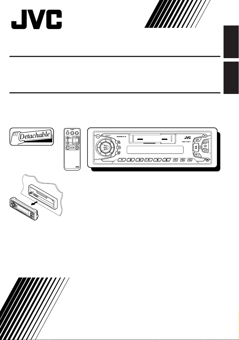
CASSETTE RECEIVER KS-FX7
DISP
SCAN
LOUD
CD CHANGER CONTROLOL
ENGLISH
RADIO KASET KS-FX7
8 9 10 11 127
CD CHANGER CONTR
Multi
Music
Scan
MO
LOUD
DISP
SCAN
RM-RK31
For installation and connections, refer to the separate manual.
Untuk instalasi dan penyambungan, lihat buku pedoman terpisah.
BAHASA
INDONESIA
INSTRUCTIONS
BUKU PETUNJUK
GET0022-001A
[UN]
Page 2
Thank you for purchasing a JVC product. Please read all instructions carefully before operation, to
ensure your complete understanding and to obtain the best possible performance from the unit.
CONTENTS
BASIC OPERATIONS .................................................... 3
RADIO OPERATIONS ................................................... 4
Listening to the radio ..................................................................... 4
ENGLISH
Storing stations in memory ............................................................ 5
FM station automatic preset: SSM .............................................. 5
Manual preset .............................................................................. 6
Tuning into a preset station ........................................................... 7
Other convenient tuner functions ................................................. 8
Scanning broadcast stations ....................................................... 8
Selecting FM reception sound ..................................................... 8
TAPE OPERATIONS ..................................................... 9
Listening to a tape .......................................................................... 9
Finding the beginning of a tune ...................................................10
Other convenient tape functions ................................................. 11
Prohibiting tape ejection ............................................................ 11
Skipping the blank portions on the tape .................................... 11
Repeat Function ........................................................................ 11
SOUND ADJUSTMENTS ............................................. 12
Turning on/off the loudness function .......................................... 12
Selecting preset sound modes ...................................................... 12
Adjusting the sound ......................................................................13
Using the Sound Control Memory .............................................. 14
Selecting and Storing the sound modes .................................... 14
Recalling the sound modes ....................................................... 15
Canceling Advanced SCM ........................................................... 16
Storing your own sound adjustments ......................................... 17
OTHER MAIN FUNCTIONS ......................................... 18
Setting the clock ............................................................................18
Selecting the level display ............................................................ 19
Detaching the control panel .........................................................20
REMOTE OPERATIONS .............................................. 21
Installing the battery .................................................................... 21
Using the remote controller ......................................................... 22
CD CHANGER OPERATIONS ...................................... 23
Playing CDs ...................................................................................23
Selecting CD playback modes ..................................................... 25
EXTERNAL COMPONENT OPERATIONS ...................... 26
Selecting the external component to use ..................................... 27
MAINTENANCE ........................................................ 28
To extend the lifetime of the unit ................................................. 28
How to Reset your unit ................................................................. 28
TROUBLESHOOTING ................................................. 29
SPECIFICATIONS .......................................................30
BEFORE USE
★
For safety....
• Do not raise the volume level too much, as this
will block outside sounds, making driving
dangerous.
• Stop the car before performing any complicated
★
Temperature inside the car....
If you have parked the car for a long time in hot
or cold weather, wait until the temperature in the
car becomes normal before operating the unit.
operations.
2
Page 3
1
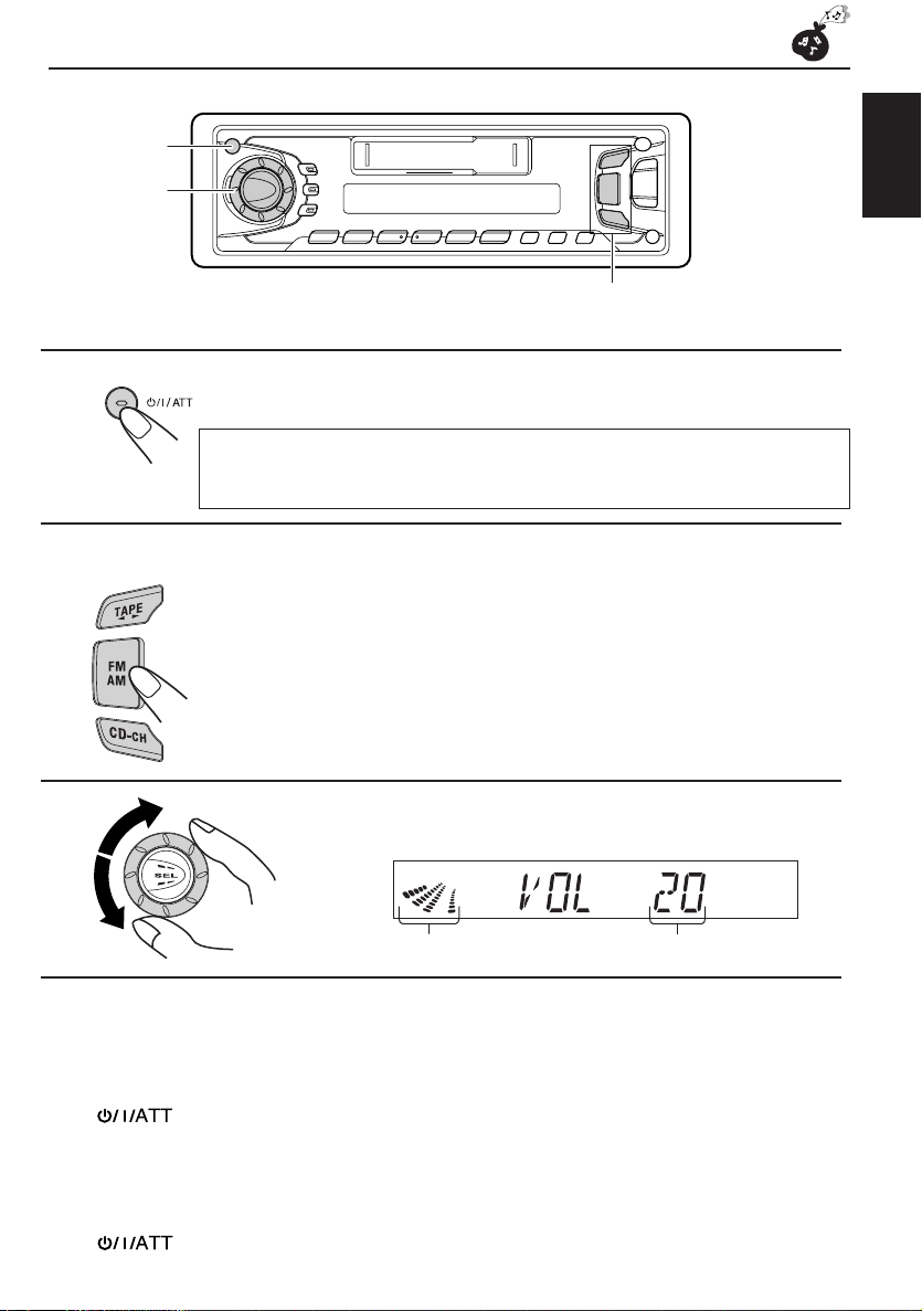
BASIC OPERATIONS
3
Note:
When you use this unit for the first time, set the built-in clock correctly, see page 18.
2
1
Turn on the power.
Note on One-Touch Operation:
When you select a source in step 2 below, the power automatically comes on.
You do not have to press this button to turn on the power.
2
Select the source.
To operate the tuner, see pages 4 – 8.
To operate the tape deck, see pages 9 – 11.
To operate the CD changer, see pages 23 – 25.
To operate the external component, see pages 26 – 27.
3
Adjust the volume.
ENGLISH
Volume level appearsVolume level indicator
4
Adjust the sound as you want (see pages 12 – 17).
To drop the volume in a moment
Press briefly while listening to any source. “ATT” starts flashing on the display, and
the volume level will drop in a moment.
To resume the previous volume level, press the button briefly again.
To turn off the power
Press for more than 1 second.
3
Page 4
RADIO OPERATIONS
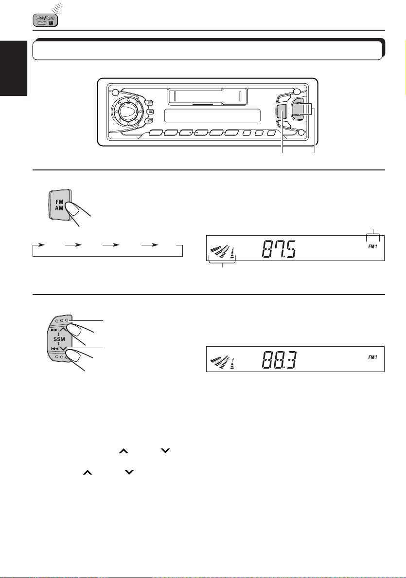
Listening to the radio
ENGLISH
21
1
Select the band (FM1, FM2, FM3 or AM).
You can select any one of FM1, FM2, and FM3 to listen to an
FM station.
FM1 FM2 FM3 AM
Audio or volume level indicator
2
To stop searching before a station is received, press the same button you have pressed
for searching.
To search stations of
higher frequencies.
To search stations of
lower frequencies.
Start searching a station.
When a station is received, searching stops.
To tune in a particular frequency manually:
1 Press FM/AM to select the band.
2 Press and hold ¢
Now you can manually change the frequency while “M” is flashing.
3 Press ¢
• If you hold down the button, the frequency keeps changing (in 50 kHz intervals for FM and
9 kHz intervals for AM – MW) until you release the button.
or 4 repeatedly until the frequency you want is reached.
or 4 until “M” starts flashing on the display.
Selected band appears
4
Page 5
Storing stations in memory
You can use one of the following two methods to store broadcasting stations in memory.
• Automatic preset of FM stations: SSM (Strong-station Sequential Memory)
• Manual preset of both FM and AM stations
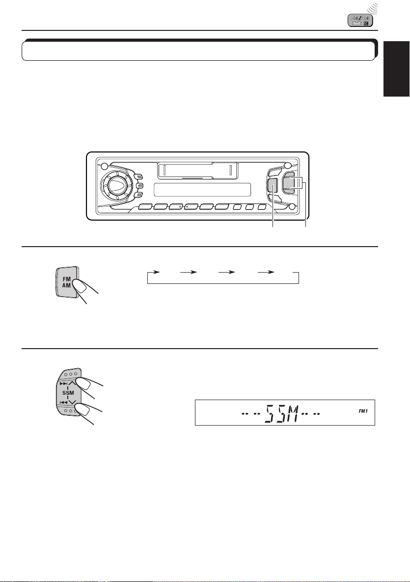
FM station automatic preset: SSM
You can preset 6 local FM stations in each FM band (FM1, FM2, and FM3).
21
ENGLISH
1
FM1 FM2 FM3
Select the FM band number (FM1, FM2 or
FM3) you want to store FM stations into.
AM
2
Press and hold the both buttons for more than
2 seconds.
“SSM” appears, then disappears when automatic
preset is over.
Local FM stations with the strongest signals are searched and stored automatically in the
band number you have selected (FM1, FM2 or FM3). These stations are preset in the number
buttons — No. 1 (lowest frequency) to No. 6 (highest frequency).
When automatic preset is over, the station stored in number button 1 will be automatically
tuned in.
5
Page 6
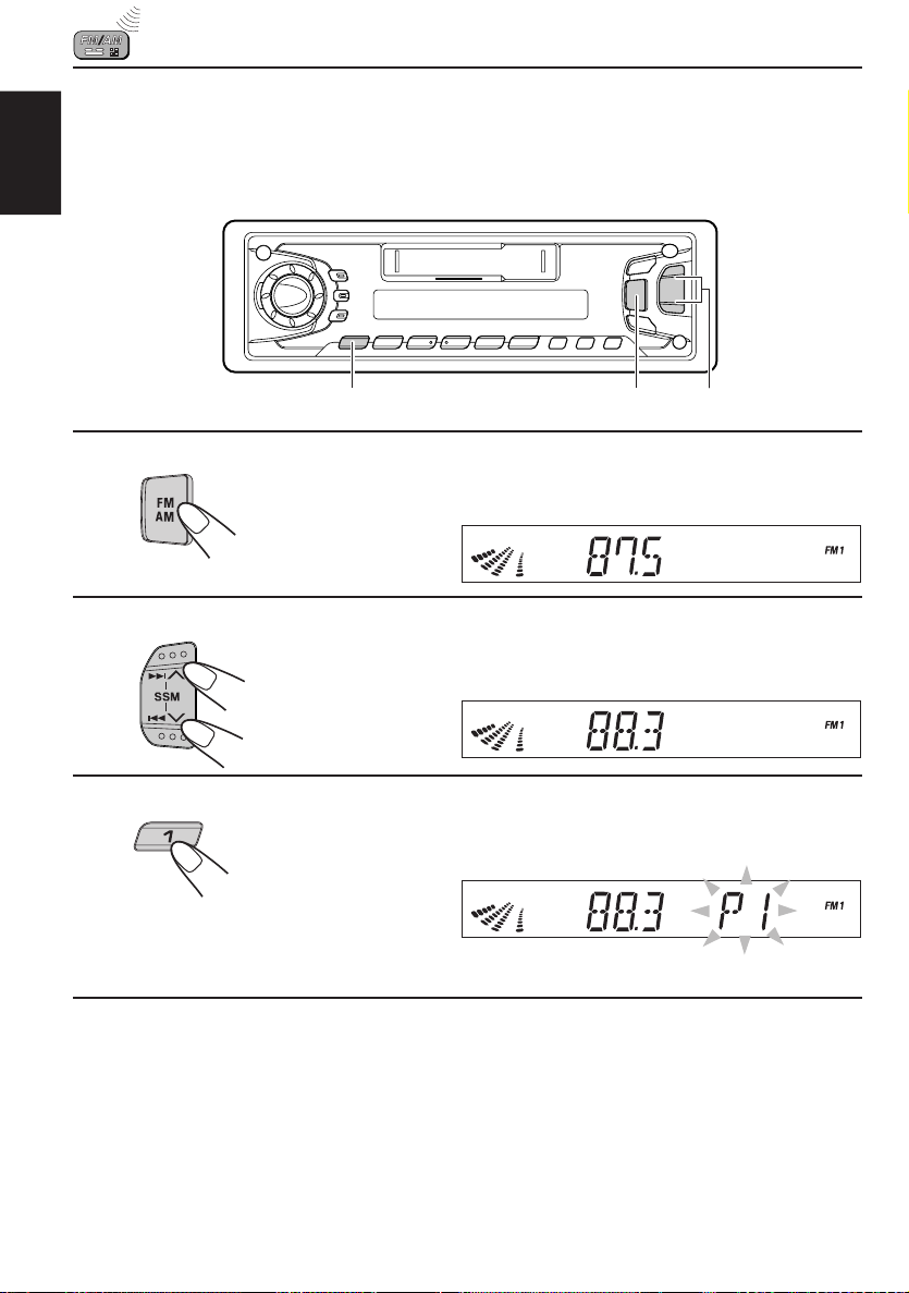
Manual preset
You can preset up to 6 stations in each band (FM1, FM2, FM3 and AM) manually.
EXAMPLE: Storing an FM station of 88.3 MHz into the preset number 1 of the FM1 band
ENGLISH
213
1
Select the FM1 band.
2
Tune into a station of 88.3 MHz.
See page 4 to tune into a station.
3
Press and hold the button for more than 2
seconds.
Preset number “P1” starts flashing for a while.
4
Repeat the above procedure to store other station into other
preset numbers.
Notes:
• A previously preset station is erased when a new station is stored in the same preset number.
• Preset stations are erased when the power supply to the memory circuit is interrupted (for example,
during battery replacement). If this occurs, preset the stations again.
6
Page 7
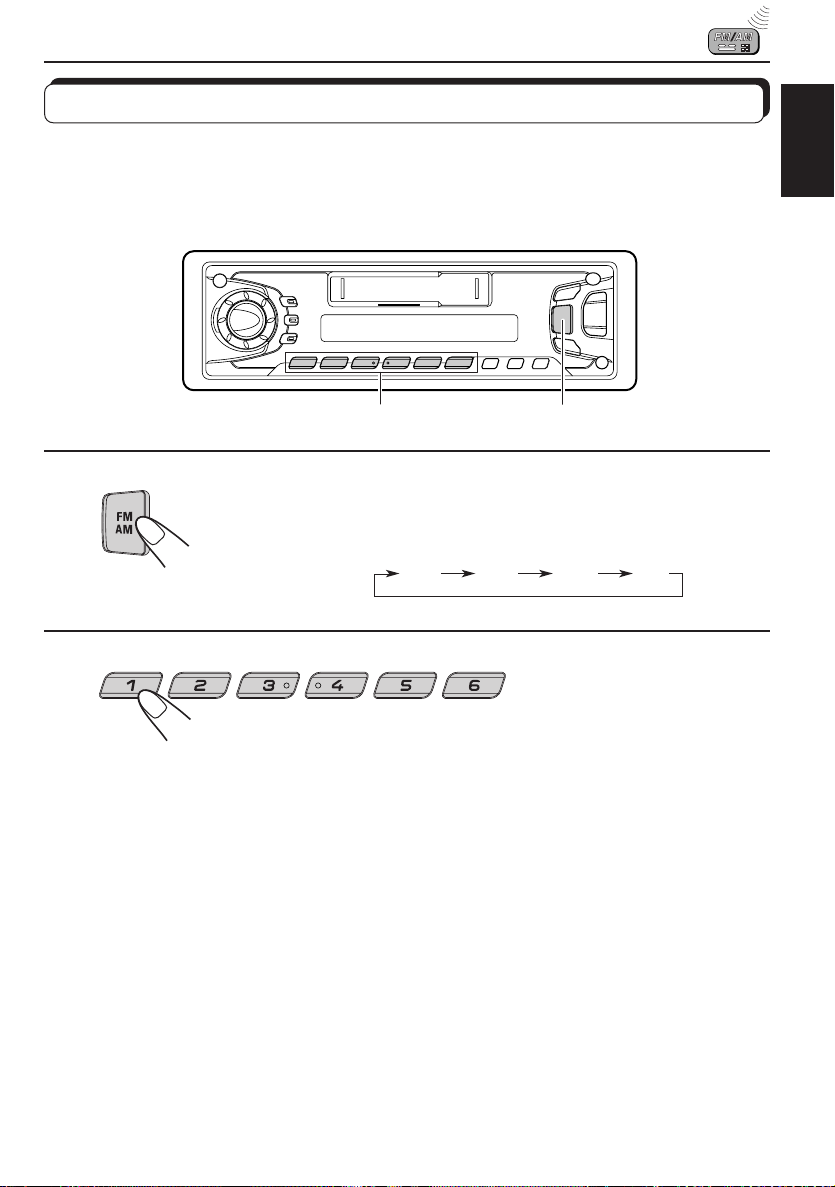
Tuning into a preset station
You can easily tune into a preset station.
Remember that you must store stations first. If you have not stored them yet, see pages 5
and 6.
12
ENGLISH
1
2
Select the band (FM1, FM2, FM3 or AM) you
want.
FM1 FM2 FM3 AM
Select the number (1 – 6) for the preset station
you want.
7
Page 8
Other convenient tuner functions
ENGLISH
SCAN
MO/RND
Scanning broadcast stations
When you press SCAN while listening to the radio, station scanning starts. Each time a
broadcast is tuned in, scanning stops for about 5 seconds (tuned frequency number flashes
on the display), and you can check what program is now being broadcasted.
If you want to listen to that program, press the same button again to stop scanning.
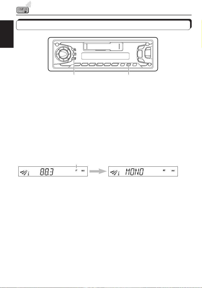
Selecting FM reception sound
When an FM stereo broadcast is hard to receive:
Press MO/RND while listening to an FM stereo broadcast. The sound you hear becomes
monaural but reception will be improved.
Lights up when receiving an
FM broadcast in stereo.
To restore the stereo effect, press the same button again.
8
Page 9
Listening to a tape
TAPE OPERATIONS
ENGLISH
21
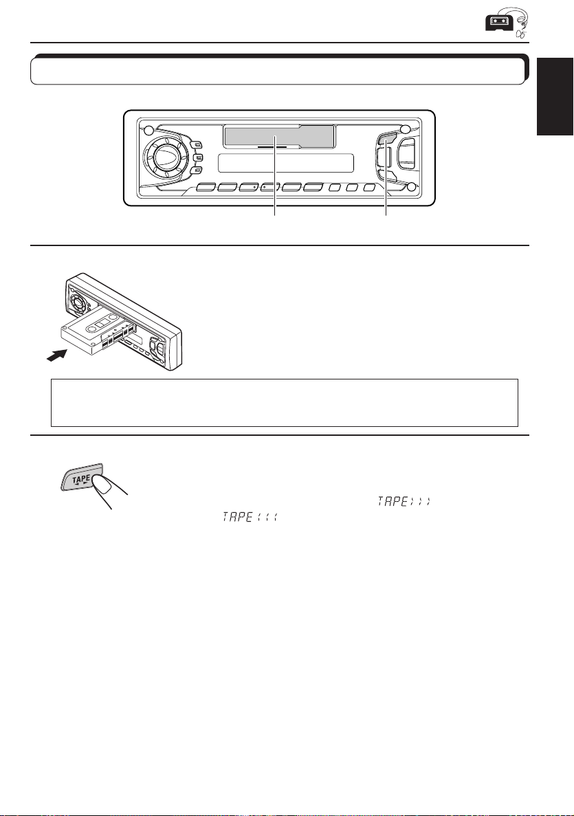
1
Insert a cassette.
The unit turns on and tape play starts automatically.
When one side of the tape reaches its end during play, the
other side of the tape automatically starts playing. (Auto
Reverse)
Note on One-Touch Operation:
When a cassette is already in the cassette compartment, pressing TAPE 23 turns on the
unit and starts tape play automatically.
2
Select the tape direction.
Each time you press the button, the tape direction changes
alternatively – forward (
(
).
To stop play and eject the cassette
Press 0.
Tape play stops and the cassette automatically ejects from the cassette compartment.
If you change the source to FM/AM or CD-CH, the tape play also stops (without ejecting the
cassette this time).
• You can also eject the tape with the unit turned off.
) and reverse
9
Page 10
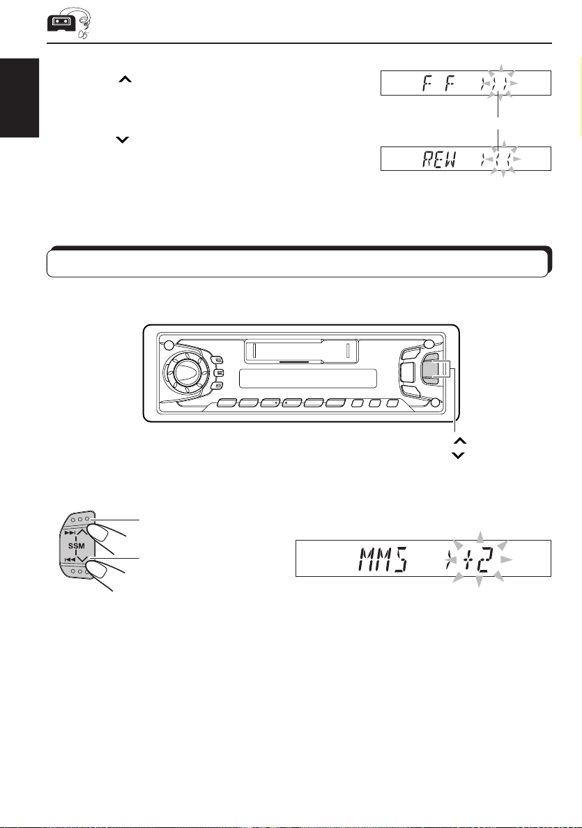
To fast-forward and rewind a tape
• Press ¢ for more than 1 second to fast-forward the
tape.
When the tape reaches its end, the tape is reversed and
playback starts from the beginning of the other side.
ENGLISH
• Press
To stop fast-forward and rewind at any position on the tape, press TAPE 23.
Tape play starts from that position on the tape.
4
When the tape reaches its end, playback of the same side
starts.
for more than 1 second to rewind the tape.
Tape direction
Finding the beginning of a tune
Multi Music Scan allows you to automatically start playback from the beginning of a specified
tune. You can specify up to 9 tunes ahead or before the current tune.
¢
4
During playback
To locate a tune
ahead of the current
tune on the tape
Specify how many tunes ahead or
before the current tune the tune you
want is located.
To locate a tune
before the current
tune on the tape
When the beginning of the specified tune is located, playback starts automatically.
Notes:
• While locating a specified tune:
– If the tape is rewound to its beginning, playback starts from the beginning of that side.
– If the tape is fast forwarded to the end, it is reversed and played from the beginning of the other
side.
• In the following cases, the Multi Music Scan function may not operate correctly.
– Tapes with tunes having long pianissimo passages (very quiet parts) or non-recorded portions
during tunes.
– Tapes with short non-recorded sections.
– Tapes with high level noise or humming between tunes.
10
Each time you set the tune, the number changes
up to ±9.
Page 11
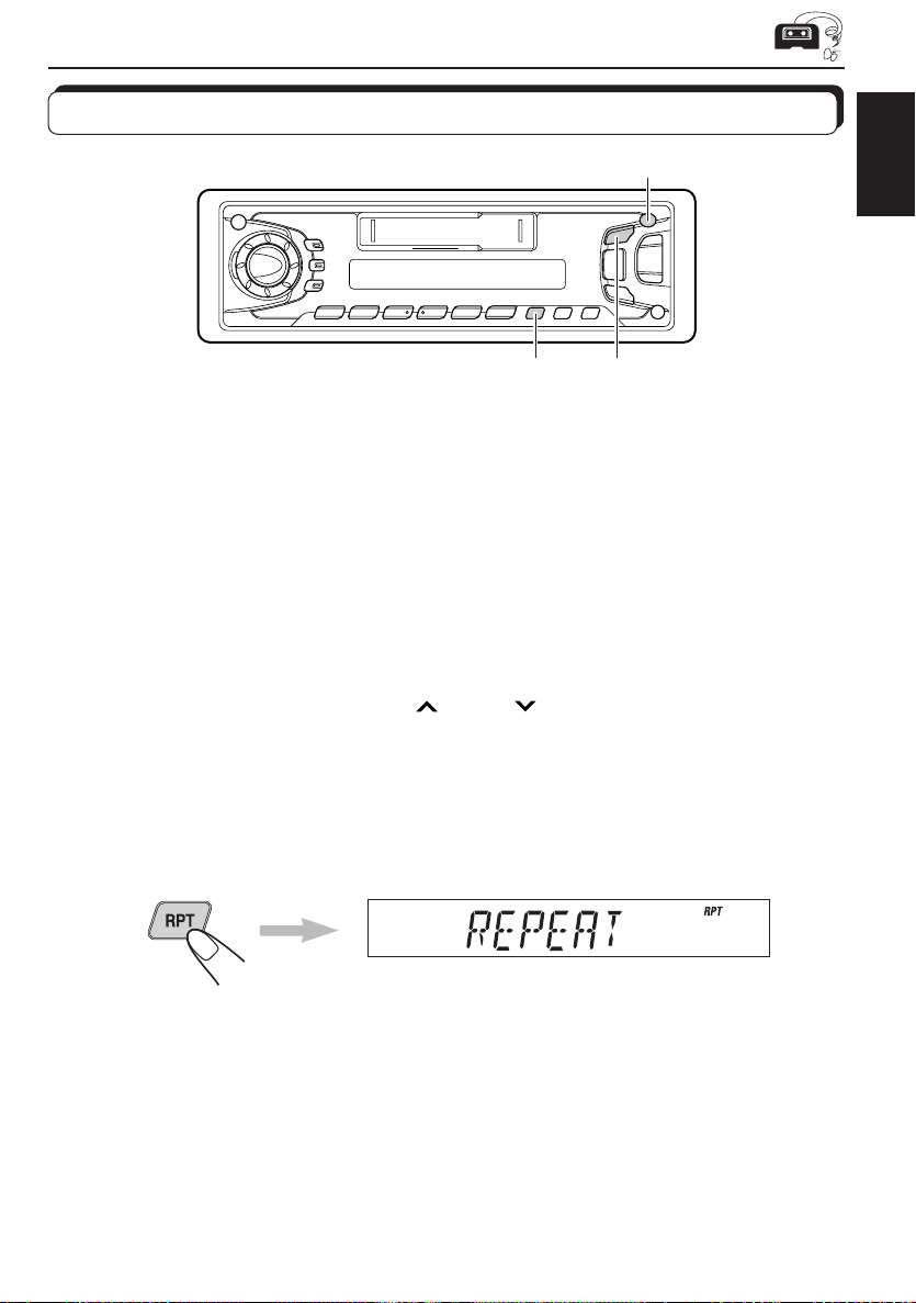
Other convenient tape functions
0
ENGLISH
RPT
TAPE
23
Prohibiting tape ejection
You can prohibit the tape ejection and can “lock” a tape in the cassette compartment.
Press and hold TAPE 23 and 0 for more than 2 seconds. “NO EJECT” flashes on the
display for about 5 seconds, and the tape is “locked.”
To cancel the prohibition and “unlock” the tape, press and hold TAPE 23 and 0 for
more than 2 seconds again. “EJECT OK” flashes again for about 5 seconds, and this time the
tape is “unlock.”
Skipping the blank portions on the tape
You can skip blank portions between the tunes. (Blank Skip)
When this function is on, the unit skips blank portions of 15 seconds or more, fast-forwards to
the next tune, then starts playing it.
1. Press and hold SEL (select) for more than 2 seconds.
ON
or 4 .
Ô
OFF
2. Select “B. SKIP (blank skip)” with ¢
3. Select the desired mode with the control dial.
The Blank Skip mode alternates between on and off.
Note:
When the tape reaches its end while fast-forwarding, the tape direction will be changed automatically.
Repeat Function
Press the RPT button while a tune you would like to hear over again is being played back.
When the tape reaches the end of the tune, the tape is automatically rewound to the beginning
of that tune and playback resumes from there. This operation will be repeated till the RPT
button is pressed again.
Notes:
In the following cases, the Multi Music Scan, and Repeat function mechanisms may not operate correctly.
These are NOT malfunctions; use the mechanisms to suitably accommodate the materials and situations.
• Tapes with tunes having long pianissimo passages (very quiet parts) or non-recorded portions during
tunes.
• Tapes with tunes recorded at low recording levels.
• Tapes with short non-recorded sections.
• Tapes with high level noise or humming between tunes.
11
Page 12

SOUND ADJUSTMENTS
Turning on/off the loudness function
The human ear is less sensitive to low and high frequencies at low volumes.
The loudness function can boost these frequencies to produce a well-balanced sound at low
ENGLISH
volume level.
Each time you press LOUD, the loudness function turns on/off alternatively.
Selecting preset sound modes
You can select a preset sound adjustment suitable to the music genre.
Each time you press SCM, the sound mode changes as follows.
Indication For: Preset values
Bass Treble Loudness
SCM OFF (Flat sound) 00 00 On
BEAT Rock or disco music +02 00 On
SOFT Quiet background music +01 –03 Off
POP Light music +04 +01 Off
Notes:
• You can adjust the preset sound mode as you like, and store in memory.
If you want to adjust and store your original sound mode, see “Storing your own sound adjustments”
on page 17.
• To adjust only the bass and treble reinforcement levels as you like, see “Adjusting the sound” on
page 13.
12
Page 13

Adjusting the sound
You can adjust the treble/bass sounds and the speaker balance.
2
1
ENGLISH
1
Select the item you want to adjust.
Indication To do: Range
BAS Adjust the bass –06 (min.) — +06 (max.)
(bass)
TRE Adjust the treble –06 (min.) — +06 (max.)
(treble)
FAD Adjust the front and rear speaker R06 (rear only) — F06 (front only)
(Fader)* balance
BAL Adjust the left and right speaker L06 (left only) — R06 (right only)
(Balance) balance
VOL Adjust the volume 00 (min.) — 50 (max.)
(Volume)
Note:
* If you are using a two-speaker system, set the fader level to “00”.
2
Adjust the level.
Note:
Normally the control dial work as the volume control buttons. So
you do not have to select “VOL” to adjust the volume level.
13
Page 14

Using the Sound Control Memory
You can select and store a preset sound adjustment suitable to each playback source.
(Advanced SCM)
ENGLISH
Selecting and storing the sound modes
Once you select a sound mode, it is stored in memory, and will be recalled every time you
select the same source. A sound mode can be stored for each of the following sources —
FM1, FM2, FM3, AM, Tape, (CD-Changer and external components).
• If you do not want to store the sound mode separately for each playback source, but want
to use the same sound mode for all the sources, see “Canceling Advanced SCM” on page
16.
“SCM” indicator
1
14
1
Select the sound mode you want.
Each time you press the button, the sound mode changes
as follows:
• When “SCM LINK” is set to “LINK ON”, the selected sound
mode can be stored in memory for the current source and
the effect applies only to the current source. Each time
you change the playback source, the SCM indicator flashes
on the display.
• When “SCM LINK” is set to “LINK OFF”, the selected sound
mode effect applies to any source.
Indication For: Preset values
Bass Treble Loudness
SCM OFF (Flat sound) 00 00 On
BEAT Rock or disco music +02 00 On
SOFT Quiet background music +01 –03 Off
POP Light music +04 +01 Off
Page 15

Recalling the sound modes
1
Select the source while the “SCM” indicator
is lit on the display.
The “SCM” indictor starts flashing, and the sound mode stored
in memory for the selected source is recalled.
Sound mode indicators
ENGLISH
1
Notes:
• You can adjust each sound mode to your preference, and store it in memory.
If you want to adjust and store your original sound mode, see “Storing your own sound adjustments”
on page 17.
• To adjust the bass and treble reinforcement levels or to turn on/off the loundness function temporarily,
see page 12 and 13. (Your adjustments will be canceled if another source is selected.)
15
Page 16

Canceling Advanced SCM
You can cancel the Advanced SCM (Sound Control Memory), and unlink the sound modes
and the playback sources.
ENGLISH
When shipped from the factory, a different sound mode can be stored in memory for each
source so that you can change the sound modes simply by changing the sources.
LINK ON: Advanced SCM (different SCM for different sources)
LINK OFF: Conventional SCM (one SCM for all sources)
3
1,4 2
1
2
3
4
Press and hold SEL for more than 2 seconds.
“CLOCK H”, “CLOCK M”, “SCM LINK”, “LEVEL”, “B.SKIP”
or “EXT IN
★
Displayed only when one of the following sources is selected—
FM, AM and TAPE.
★
” appears on the display.
Select “SCM LINK” if not shown on the display.
Select the desired mode — “LINK ON” or
“LINK OFF”.
Finish the setting.
16
Page 17

Storing your own sound adjustments
You can adjust the sound modes (BEAT, SOFT, POP: see page 12) as you like and store your
own adjustments in memory.
3
ENGLISH
1
2
3
4
Within
5 seconds
Within
5 seconds
Within
5 seconds
2
1,42
Call up the sound mode you want to adjust.
See page 12 for details.
To adjust the bass or treble sound level
Select “BAS” or “TRE.”
To turn on or off the loudness function
Each time you press LOUD, the loudness function turns on
and off alternatively. (= go to step 4)
Adjust the bass or treble level.
See page 13 for details.
Press and hold SCM until the sound mode
you have selected in step
1
flashes on the
display.
Your setting is stored in memory.
5
Repeat the same procedure to store other settings.
To reset to the factory settings
Repeat the same procedure and reassign the preset values listed in the table on page 12.
17
Page 18
OTHER MAIN FUNCTIONS
Clock
LINE IN
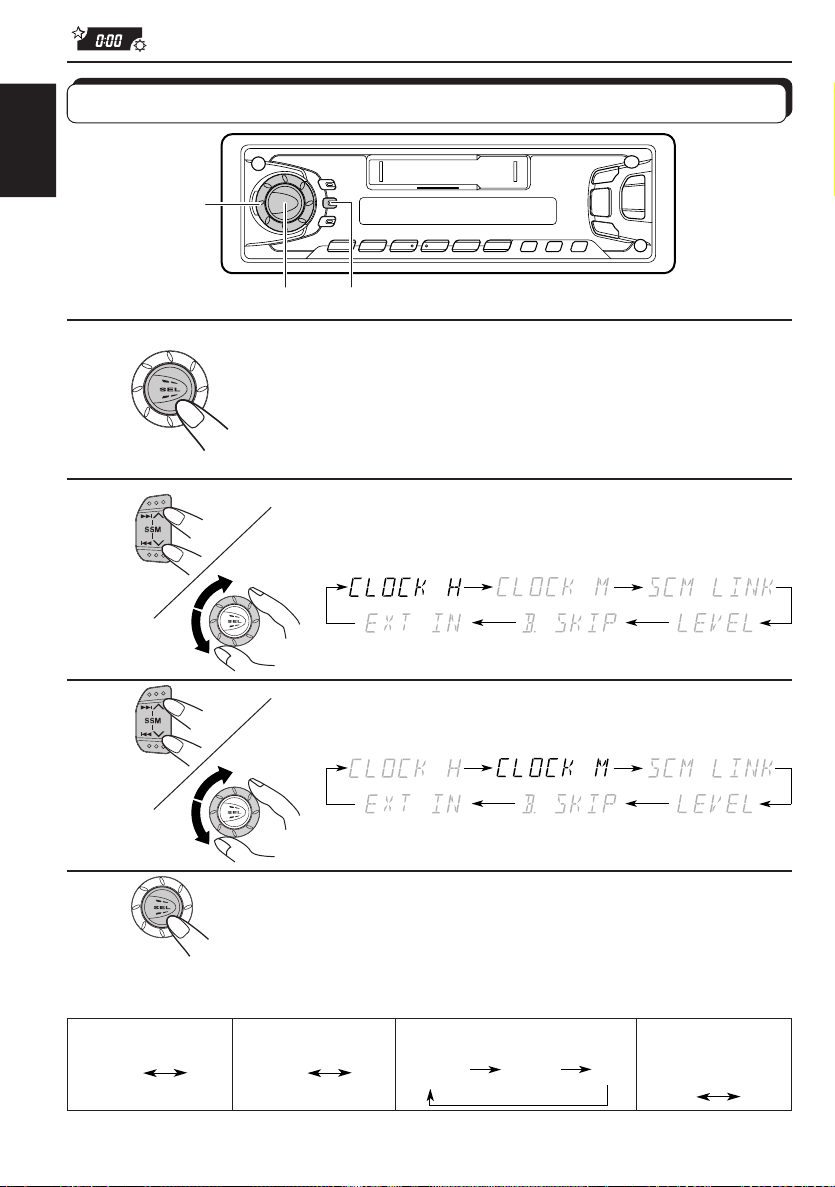
Setting the clock
ENGLISH
2,3
1
2
3
1.
1.
2.
2.
1,4
DISP
Press and hold the button for more than 2
seconds.
“CLOCK H,” “CLOCK M”, “SCM LINK”, “LEVEL”, “B.SKIP”
or “EXT IN
★
Displayed only when one of the following sources is selected —
FM, AM and TAPE.
★
” appears on the display.
Set the hour.
1. Select “CLOCK H” if not shown on the
display.
2. Adjust the hour.
Set the minute.
1. Select “CLOCK M.”
2. Adjust the minute.
4
Finish the setting.
To check the current clock time (changing the display mode)
Press DISP repeatedly. Each time you press the button, the display mode changes as follows.
During tuner operation:
Frequency
• If the unit is not in use when you press DISP, the power turns on, the clock time is shown for
18
5 seconds, then the power turns off.
During tape operation:
Clock
Play mode
During CD Changer operation:
playing time
transcurrido
Tiempo de
Elapsed
reproducción
Clock
Número
Disc
de disco
number
During external
Component operation:
Clock
Hora
Page 19

Selecting the level display
You can select the level display according to your preference.
When shipped from the factory, “AUDIO 2” is selected.
AUDIO1: Shows the audio level indicator.
AUDIO2: Alternates “AUDIO 1” setting and illumination display.
OFF : Erases the audio level indicator.
3
1,4 2
ENGLISH
1
2
3
4
Press and hold SEL for more than 2 seconds.
“CLOCK H”, “CLOCK M”, “SCM LINK”, “LEVEL”, “B.SKIP”
or “EXT IN
★
Displayed only when one of the following sources is selected —
FM, AM and TAPE.
★
” appears on the display.
Select “LEVEL” if not shown on the display.
Select the desired mode — “AUDIO 1”,
“AUDIO 2” or “OFF”.
Finish the setting.
19
Page 20

Detaching the control panel
You can detach the control panel when leaving the car.
When detaching or attaching the control panel, be careful not to damage the connectors on
ENGLISH
the back of the control panel and on the panel holder.
How to detach the control
panel
Before detaching the control panel, be sure
to turn off the power.
1
Unlock the control panel.
2
Lift and pull the control panel
out of the unit.
How to attach the control
panel
1
Insert the left side of the
control panel into the groove
on the panel holder.
2
Press the right side of the
control panel to fix it to the
panel holder.
20
Note on cleaning the connectors:
If you frequently detach the control panel, the
connectors will deteriorate.
To minimize this possibility, periodically wipe
the connectors with a cotton swab or cloth
moistened with alcohol, being careful not to
damage the connectors.
Connectors
Page 21

REMOTE OPERATIONS
Remote sensor
Before using the remote controller:
• Aim the remote controller directly at the remote sensor
on the main unit. Make sure there is no obstacle in
between.
• Do not expose the remote sensor to strong light (direct
sunlight or artificial lighting).
Installing the battery
When the controllable range or effectiveness of the remote controller decreases, replace
the battery.
1. Remove the battery holder.
(back side)
1)
2)
1) Push out in the direction indicated by the arrow
using a ball point pen or a similar tool.
2) Remove the battery holder.
ENGLISH
Lithium coin battery
(product number:
CR2025)
(back side)
WARNING:
• Store the batteries in a place which children cannot reach.
If a child accidentally swallows the battery, immediately consult a doctor.
• Do not recharge, short, disassemble or heat the batteries or dispose of in a fire.
Doing any of these things may cause the batteries to give off heat, crack or start a fire.
• Do not leave the batteries with other metallic materials.
Doing this may cause the batteries to give off heat, crack or start a fire.
• When throwing away or saving the batteries, wrap in tape and insulate; otherwise, , it may cause
the batteries to give off heat, crack or start a fire.
• Do not poke the batteries with tweezers or similar tools.
Doing this may cause the batteries to give off heat, crack or start a fire.
2. Place the battery.
Slide the battery into the holder with the + side facing
upwards so that the battery is fixed in the holder.
3. Return the battery holder.
Insert again the battery holder pushing it until you hear
a clicking sound.
21
Page 22

Using the remote controller
1 Functions the same as the button on the main unit.
5
ENGLISH
1
2
3
4
RM-RK31
2 • Functions as the BAND button while listening to the radio.
6
7
Each time you press the button, the band changes.
• Functions as the DISC + button while listening to the CD
changer.
Each time you press the button, the disc number increases,
and the selected disc starts playing.
• Does not function as the PROG button.
3 • Functions as the PRESET button while listening to the
radio.
Each time you press the button, the preset station number
increases, and the selected station is tuned in.
• Functions as the DISC – button while listening to the CD
changer.
Each time you press the button, the disc number decreases,
and the selected disc starts playing.
4 Functions the same as the control dial on the main unit.
Note: These buttons cannot be used for the clock (CLOCK H,
5 Selects the sound mode.
Each time you press SCM (Sound Control Memory), the mode
changes.
6 Selects the source.
Each time you press FUNC (function), the source changes.
7 • Searches stations while listening to the radio.
• Fast forwards or reverses the track if pressed and held
while listening to a CD.
• Skips to the beginning of the next tracks or goes back to
the beginning of the current (or previous tracks) if pressed
briefly while listening to a CD.
• Functions as the fast forward or rewind buttons or Multi
Music Scan buttons while listening to a tape.
CLOCK M), SCM LINK, LEVEL, B. SKIP and EXT IN
adjustments (see pages 18, 16, 19, 11 and 27).
22
Page 23

CD CHANGER OPERATIONS
When used with a JVC CD automatic changer (separately purchased).
We recommend that you use one of the CH-X series with your unit.
If you have another CD automatic changer, consult your JVC car audio dealer for connections.
• For example, if your CD automatic changer is one of the KD-MK series, you need a cord (KSU15K) for connecting it to this unit.
Before operating your CD automatic changer:
• Refer also to the Instructions supplied with your CD changer.
• If no discs are in the magazine of the CD changer or the discs are inserted upside
down, “NO CD” or “NO DISC” will appear on the display. If this happens, remove the
magazine and set the discs correctly.
• If “RESET 1 - RESET 8” appears on the display, something is wrong with the connection
between this unit and the CD changer. If this happens, check the connection, connect
the connecting cord(s) firmly if necessary, then press the reset button of the CD changer.
Playing CDs
ENGLISH
Number buttons
1
1
Select the CD automatic changer.
Play back starts from the first track of the first disc.
All tracks of all discs are played back.
Disc number
Track number Elapsed playing time
Note on One-Touch Operation:
When you press CD-CH, the power automatically comes on. You do not have to press
to turn on the power.
(The clock time is shown if you have pressed
DISP to see the clock time. See page 18.)
¢
4
23
Page 24

To fast forward or reverse the track
Press and hold ¢ , while playing a CD, to fast forward the track.
ENGLISH
Press and hold 4
, while playing a CD, to reverse the track.
To go to the next track or the previous track
Press ¢ briefly, while playing a CD, to go ahead to the beginning
of the next track. Each time you press the button consecutively, the
beginning of the next tracks is located and played back.
Press 4
of the current track. Each time you press the button consecutively,
the beginning of the current tracks is located and played back.
briefly, while playing a CD, to go back to the beginning
To go to a particular disc directly
Press the number button corresponding to the disc number to start its
playback.
• To select a disc number from 1 – 6:
Press 1 (7) – 6 (12) briefly.
• To select a disc number from 7 – 12:
Press and hold 1 (7) – 6 (12) for more than 1 second.
Ex. When disc number 3 is selected
Disc number
24
Track number
Page 25

Selecting CD playback modes
MO/RND
RPT
To play back tracks at random (Random Play)
Each time you press MO/RND (Mono/Random) while playing a CD,
MO
Mode RND Indicator Plays at random
RND1 Lights All tracks of the current disc, then the tracks of the
RND2 Flashes All tracks of all discs inserted in the magazine.
CD random play mode changes as follows:
RND1 RND2 Canceled
(Random1) (Random2)
next disc, and so on.
ENGLISH
To play back tracks repeatedly (Repeat Play)
Each time you press RPT (Repeat) while playing a CD, CD repeat play
mode changes as follows:
RPT1 RPT2 Canceled
(Repeat1) (Repeat2)
Mode RPT Indicator Plays repeatedly
RPT1 Lights The current track (or specified track).
RPT2 Flashes All tracks of the current disc (or specified disc).
25
Page 26

EXTERNAL COMPONENT OPERATIONS
You can connect the external component to the CD changer jack on the rear using the Line
Input Adaptor KS-U57 (not supplied).
ENGLISH
3
1
Preparations:
• For connecting the Line Input Adaptor KS-U57 and the external component, refer to the Installation/
Connection Manual (separate volume).
• Before operating the external component using the following procedure, select the external input
correctly. (See “Selecting the external component to use” on page 27.)
1
Select the external component.
• If “LINE IN” does not appear on the display, see page 27
and select the external input (“EXT IN”).
Note on One-Touch Operation:
When you press CD-CH, the power automatically comes on. You do not have to press
to turn on the power.
2
Turn on the connected device and start playing the source.
3
To turn up the
volume
Adjust the volume.
To turn down
the volume
26
Page 27

Selecting the external component to use
You can connect the external component to the CD changer jack on the rear using the Line
Input Adaptor KS-U57 (not supplied).
To use the external component as the playback source through this receiver, you need to
select which device — CD changer or external component — to use. When shipped from the
factory, CD changer is selected as the external component.
LINE IN: To use the external component other than CD changer
CHANGER: To use the CD changer
4
ENGLISH
1
2
3
4
2,5
31
Change the source to FM, AM or TAPE.
Press and hold SEL for more than 2 seconds.
“CLOCK H”, “CLOCK M”, “SCM LINK”, “LEVEL”, “B.SKIP”
or “EXT IN” appears on the display.
Select “LINE IN” if not shown on the display.
Select the desired mode — “LINE IN” or
“CHANGER”.
5
Finish the setting
Note:
• For connecting the Line Input Adaptor KS-U57 and the external component, refer to the
Installation/connection Manual (separate volume).
27
Page 28

MAINTENANCE
To extend the lifetime of the unit
This unit requires very little attention, but you will be able to extend the life of the unit if you
follow the instructions below.
ENGLISH
To clean the heads
• Clean the heads after every 10 hours of use using a
wet-type head cleaning tape (available at an audio store).
When the head becomes dirty, you may realize the
following symptoms:
– Sound quality is reduced.
– Sound level decreases.
– Sound drops out.
• Do not play dirty or dusty tapes.
• Do not touch the highly-polished head with any metallic
or magnetic tools.
To keep the tape clean
• Always store the tapes to their storage cases after use.
• Do not store tapes in the following places:
– Subject to direct sunlight
– With high humidity
– At extremely hot temperatures
CAUTIONS:
• Do not play the tapes with peeling labels; otherwise, they can damage the unit.
• Tighten tapes to remove slack since loose tape may become entangled with the mechanism.
• Do not leave a cassette in the cassette compartment after use, as the tape may become slack.
The function below is also provided to ensure the longer life of this unit.
Ignition key-off Release/Ignition key-on play
• When you turn off the ignition key with a cassette in the compartment, the unit automatically
releases the tape from its head.
• When you turn on the ignition key with a cassette in the compartment, playback automatically
starts.
How to Reset your unit
Press and hold both the SEL (Select) and (Standby/On/ATT) buttons at the
same time for several seconds.
This will reset the built-in microcomputer.
NOTE: Your preset adjustments — such as preset channels or sound adjustments —
28
will also be erased.
(Standby/On/ATT)
SEL (Select)
Page 29

TROUBLESHOOTING
What appears to be trouble is not always serious. Check the following points before calling a
service center.
Symptoms
• A cassette tape cannot be
inserted.
• Cassette tapes become hot.
• Tape sound is at very low
level and sound quality is
degraded.
• Sound is sometimes
interrupted.
• Sound cannot be heard from
the speakers.
• SSM (Strong-station
Sequential Memory)
automatic preset does not
work.
• Static noise while listening
to the radio.
•“NO CD” or “NO DISC”
appears on the display.
Causes
You have tried to insert a
cassette in the wrong way.
This is not a malfunction.
The tape head is dirty.
Connections are not good.
The volume control is turned
to the minimum level.
Connections are incorrect.
Signals are too weak.
The antenna is not connected
firmly.
No CD is in the magazine.
Remedies
ENGLISH
Insert the cassette with the
exposed tape facing right.
Clean it with a head cleaning
tape.
Check the cords and
connections.
Adjust it to the optimum level.
Check the cords and
connections.
Store stations manually.
Connect the antenna firmly.
Insert CDs into the magazine.
•“RESET 8” appears on the
display.
•“RESET 1-RESET 7”
appears on the display.
• The unit does not work at
all.
• The CD changer does not
work at all.
CDs are inserted incorrectly.
This unit is not connected to a
CD changer correctly.
The built-in microcomputer
may function incorrectly due
to noise, etc.
Insert them correctly.
Connect this unit and the CD
changer correctly and press
the reset button of the CD
changer.
Press the reset button of the
CD changer.
Press
the same time for more than 2
seconds to reset the unit. (The
clock setting and preset
stations stored in memory are
erased.) (See page 28).
and SEL at
29
Page 30

SPECIFICATIONS
AUDIO AMPLIFIER SECTION
Maximum Power Output:
Front: 40 watts per channel
Rear: 40 watts per channel
Continuous Power Output (RMS):
ENGLISH
Front: 16 watts per channel into 4 Ω, 40
Hz to 20 000 Hz at no more than
0.8% total harmonic distortion.
Rear: 16 watts per channel into 4 Ω, 40
Hz to 20 000 Hz at no more than
0.8% total harmonic distortion.
Load Impedance: 4 Ω (4 Ω to 8 Ω allowance)
Tone Control Range
Bass: ±10 dB at 100 Hz
Treble:±10 dB at 10 kHz
Frequency Response: 40 Hz to 20 000 Hz
Signal-to-Noise Ratio: 70 dB
Line-Out Level/Impedance:
2.0 V/20 kΩ load
TUNER SECTION
Frequency Range
FM: 87.5 MHz to 108.0 MHz
AM: 531 kHz to 1 602 kHz
[FM Tuner]
Usable Sensitivity: 11.3 dBf (1.0 µV/75 Ω)
50 dB Quieting Sensitivity:
16.3 dBf (1.8 µV/75 Ω)
Alternate Channel Selectivity (400 kHz):
65 dB
Frequency Response: 40 Hz to 15 000 Hz
Stereo Separation: 30 dB
Capture Ratio: 1.5 dB
CASSETTE DECK SECTION
Wow & Flutter: 0.11% (WRMS)
Fast-Wind Time: 100 sec. (C-60)
Frequency Response:
30 Hz to 16 000 Hz (± 3 dB)
Signal-to-Noise Ratio: (Normal tape) 56 dB
Stereo Separation: 40 dB
GENERAL
Power Requirement
Operating Voltage: DC 14.4 volts (11 volts to
16 volts allowance)
Grounding System: Negative ground
Allowable Working Temperature:
0°C to + 40°C (32°F to 104°F)
Dimensions (W x H x D)
Installation Size:
182 mm x 52 mm x 150 mm
Panel Size:
188 mm x 58 mm x 14 mm
Mass: 1.4 kg (3.1 lbs) (excluding accessories)
Design and specifications subject to change
without notice.
Having TROUBLE with operation?
Please reset your unit
Refer to page of How to Reset
[AM Tuner]
Sensitivity: 20 µV
Selectivity: 30 dB
30
Page 31

Having TROUBLE with operation?
Please reset your unit
Refer to page of How to Reset your unit.
Still having trouble??
Ada MASALAH dengan cara
pengoperasian?
Setel kembali unit Anda
Lihat halaman mengenai Cara melakukan
Penyetelan Ulang
Masih bermasalah??
EN, IN
VICTOR COMPANY OF JAPAN, LIMITED
0201HISFLEJES
JVC
Page 32

KS-FX7
Installation/Connection Manual
Buku Petunjuk Instalasi/Penyambungan
GET0022-002A
[UN]
ENGLISH
• This unit is designed to operate on 12 volts DC, NEGATIVE ground electrical systems.
INSTALLATION (IN-DASH MOUNTING)
• The following illustration shows a typical installation. However, you should make adjustments
corresponding to your specific car. If you have any questions or require information regarding
installation kits, consult your JVC car audio dealer or a company supplying kits.
1
Before mounting: Press (Control Panel Release) to detach the control panel if already
attached.
2
Remove the trim plate.
3
Do the required electrical connections explained on the back of this instructions.
4
Refer to 'Installing the unit'.
5
Attach the trim plate.
6
Attach the control panel.
1
0201HISFLEJES
JVC
EN, IN
BAHASA INDONESIA
• Unit ini dirancang untuk beroperasi dengan daya 12 volt DC, sistem listrik arde NEGATIF.
INSTALASI (PEMASANGAN DALAM DASBOR)
• Ilustrasi berikut ini menunjukkan cara instalasi yang umum dilakukan. Tetapi, sebaiknya Anda
melakukan penyesuaian yang diperlukan untuk mobil Anda. Jika ada pertanyaan atau Anda
memerlukan informasi mengenai kotak instalasi, hubungi dealer audio mobil JVC Anda atau
perusahaan yang memasok kotak instalasi tersebut.
1
Sebelum pemasangan: Tekan (Pelepas Panel Pengendali) untuk melepaskan panel
pengendali jika sudah terpasang.
2
Lepaskan plat bingkai.
3
Lakukan penyambungan listrik sebagaimana yang dijelaskan di bagian belakang petunjuk ini.
4
Lihat “Instalasi unit”.
5
Pasang plat bingkai.
6
Pasang panel pengendali.
Binding head or Flat head screws (M5 x 6 mm)
Sekrup kepala bulat atau Sekrup kepala datar (M5 x 6 mm)
Dashboard
Dasbor
2
6
5
Trim plate
Plat bingkai
4
Bracket*
Penyangga*
Pocket
Kantung
Bracket*
Penyangga*
See the back page for electrical
3
connections.
Lihat halaman belakang untuk
penyambungan listrik.
5
10
2
1
3
1
2
3
4
5
Binding head or Flat head
screws (M5 x 6 mm)
Sekrup kepala bulat atau
Sekrup kepala datar
(M5 x 6 mm)
• Installing the unit
• Instalasi unit
Install the unit in its place.
Pasang unit pada tempatnya.
Binding head or Flat head
screws (M5 x 6 mm)
Sekrup kepala bulat
atau Sekrup kepala
datar (M5 x 6 mm)
Bracket*
Penyangga*
Pocket
Kantung
Note: When installing the unit on the mounting bracket, make sure to use the 6 mm-long screws.
If longer screws are used, they could damage the unit.
Catatan: Saat memasang unit pada penyangga, pastikan bahwa yang digunakan adalah sekrup dengan
panjang 6 mm. Jika menggunakan sekrup yang lebih panjang, kemungkinan akan merusak unit.
Bracket*
Penyangga*
* Not included with this unit.
* Tidak disertakan dalam unit ini.
Binding head or
Flat head screws (M5 x 6 mm)
Sekrup kepala bulat atau
Sekrup kepala datar
(M5 x 6 mm)
Parts list for installation and connection
The following parts are provided with this unit.
After checking them, please set them correctly.
Daftar bagian-bagian yang digunakan untuk instalasi dan penyambungan.
Bagian-bagian berikut ini disertakan bersama unit ini.
Sesudah diperiksa, pasang bagian-bagian tersebut dengan benar.
Control Panel
Panel Pengendali
Trim plate
Plat Bingkai
Power cord
Kabel listrik
Remote controller
Pengendali jarak jauh
Flat head
Kepala datar
x 4
Binding head
Kepala bulat
x 4
Battery
Baterai
CR2025
Page 33

ENGLISH
BAHASA INDONESIA
ELECTRICAL CONNECTIONS
To prevent short circuits, we recommend that you disconnect the battery’s negative terminal and
make all electrical connections before installing the unit. If you are not sure how to install this unit
correctly, have it installed by a qualified technician.
Note:
This unit is designed to operate on 12 volts DC, NEGATIVE ground electrical systems. If your
vehicle does not have this system, a voltage inverter is required, which can be purchased at JVC
car audio dealers.
• Replace the fuse with one of the specified rating. If the fuse blows frequently, consult your JVC
car audio dealer.
• If noise is a problem...
This unit incorporates a noise filter in the power circuit. However, with some vehicles, clicking or
other unwanted noise may occur. If this happens, connect the unit’s rear ground terminal (See
connection diagram below.) to the car’s chassis using shorter and thicker cords, such as copper
braiding or gauge wire. If noise still persists, consult your JVC car audio dealer.
• Maximum input of the speakers should be more than 40 watts at the rear and 40 watts at the
front, with an impedance of 4 to 8 ohms.
• Be sure to ground this unit to the car’s chassis.
• The heat sink becomes very hot after use. Be careful not to touch it when removing this unit.
Heat sink
Penyerap panas
PENYAMBUNGAN LISTRIK
Untuk mencegah korsleting, kami menyarankan agar Anda memutuskan hubungan terminal negatif
baterai dan memasang semua sambungan listrik sebelum memasang unit. Jika Anda tidak yakin
bagaimana memasang unit ini dengan benar, sebaiknya pemasangan dilakukan oleh teknisi yang
memenuhi syarat.
Catatan:
Unit ini dirancang untuk beroperasi dengan daya 12 volts DC, sistem listrik arde NEGATIF. Jika
mobil Anda tidak mempunyai sistem ini, maka Anda memerlukan inverter/pembalik voltase yang
dapat Anda peroleh di dealer audio mobil JVC.
• Ganti sekering dengan sekering lain yang sesuai dengan syarat spesifikasi. Jika sekering sering
putus, hubungi dealer audio mobil JVC Anda.
• Jika terdengar bunyi yang menggangu...
Unit ini mempunyai filter suara dalam sirkuit dayanya. Tetapi pada beberapa mobil, bunyi klik
dan bunyi-bunyi lain yang mengganggu dapat saja terjadi. Jika hal ini terjadi, hubungkan terminal
arde belakang (Lihat diagram penyambungan di bawah.) ke casis mobil dengan menggunakan
kabel yang lebih pendek dan tebal, misalnya kabel tembaga jalin atau kabel gauge. Jika bunyi
tetap terdengar, hubungi dealer audio mobil JVC Anda.
• Input maksimum speaker sebaiknya tidak lebih dari 40 watt untuk speaker belakang dan 40
watt untuk speaker depan, dengan impedansi 4 sampai 8 ohm.
• Pastikan bahwa unit dihubungkan ke arde di casis mobil.
• Penyerap panas (heat sink) akan menjadi sangat panas sesudah unit digunakan. Hati-hati jangan
sampai tersentuh saat memindahkan unit ini.
A Typical Connections
Before connecting: Check the wiring in the vehicle carefully. Incorrect connection may cause
serious damage to this unit.
1
Connect the colored leads of the power cord to the car battery, speakers and automatic
antenna (if any) in the following sequence.
1 Black: ground
2 Yellow: to car battery (constant 12V)
3 Red: to an accessory terminal
4 Blue with white stripe: to automatic antenna (200mA max.)
5 Others: to speakers
2
Connect the antenna cord.
3
Finally connect the wiring harness to the unit.
* Before connecting the CD changer, make sure that the unit is turned off.
* Sebelum menghubungkan CD changer, pastikan bahwa unit sudah dimatikan.
JVC CD changer jack
Lubang kontak JVC CD changer
Left
Kiri
Line out
(see diagram B )
Sambungan kabel luar
(lihat diagram B )
Antenna terminal
Terminal antena
2
Right
Kanan
10A fuse
Sekering 10A
3
10
JVC CD changer jack or another
external component
Lubang kontak JVC CD changer
atau komponen eksternal
lainnya.
Rear ground terminal
Terminal arde belakang
Black
Hitam
1
A Penyambungan Umum
Sebelum penyambungan: Periksa dengan cermat pemasangan listrik mobil. Sambungan yang
tidak benar dapat menyebabkan kerusakan pada unit ini.
1
Hubungkan kabel-kabel berwarna dari kabel daya ke aki mobil, speaker dan antena
otomatis (jika ada) dengan urutan sebagai berikut.
1 Hitam: arde
2 Kuning: ke aki mobil (12V konstan)
3 Merah: ke terminal aksesori
4 Biru bergaris putih: ke antena otomatis (maksimum 200mA)
5 Lain-lain: ke speaker
2
Hubungkan kabel antena
3
Terakhir hubungkan pengikat kabel ke unit.
When connecting a CD changer, we recommend to use one of the CH-X series CD changers.
• If your CD changer is one of the KD-MK series, you need an optional cord (KS-U15K).
You can also use an external component such as a portable MD player by connecting the Line Input Adaptor
KS-U57 (not supplied) (see diagram B )
Sewaktu menghubungkan CD changer, kami sarankan untuk menggunakan salah satu dari CD
changer seri CH-X.
• Jika CD changer Anda salah satu dari seri KD-MK, Anda memerlukan kabel tambahan (KS-U15K).
Anda juga dapat menggunakan komponen eksternal seperti MD player jinjing dengan menghubungkan Line Input
Adaptor KS-U57 (tidak disediakan) (lihat diagram B )
To metallic body or chassis of the car
Ke badan logam atau casis mobil.
* Not included with this unit.
* Tidak disertakan dalam unit ini
*
*
Ignition switch
Kunci starter
To antenna
Ke antena
1
*1:Before checking the operation of this unit prior to
installation, this lead must be connected, otherwise
power cannot be turned on.
*1: Sebelum memeriksa pengoperasian unit ini sebelum
instalasi, kabel ini harus disambungkan, kalau tidak daya
tidak dapat dinyalakan.
White with black stripe
Putih bergaris hitam
White
Putih
Left speaker (front)
Speaker kiri (depan)
Gray with black stripe
Abu-abu bergaris hitam
5
1
Yellow*
1
Kuning*
2
Red
Merah
Blue with white stripe
Biru bergaris putih
Gray
Abu-abu
Right speaker (front)
Speaker kanan (depan)
To a live terminal in the fuse block connecting to the car
battery (bypassing the ignition switch)
Ke terminal yang menyala di dalam blok sekering yang
tersambung dengan aki mobil (melalui kunci starter).
To an accessory terminal in the fuse block.
3
Ke terminal aksesori dalam blok sekering.
4
Green with black stripe
Hijau bergaris hitam
Green
Hijau
Left speaker (rear)
Speaker kiri (belakang)
Purple with black stripe
Ungu bergaris hitam
Fuse block
Blok sekering
To automatic antenna if any
Ke antena otomatis, jika ada
Purple
Ungu
Right speaker (rear)
Speaker kanan (belakang)
Page 34

PRECAUTIONS on power supply and speaker connections:
• DO NOT connect the speaker leads of the power cord to the car battery; otherwise, the unit will
be seriously damaged.
• Connect the black lead (ground), yellow lead (to car battery, constant 12V), and red lead (to an
accessory terminal) correctly.
• BEFORE connecting the speaker leads of the power cord to the speakers, check the speaker
wiring in your car.
– If the speaker wiring in your car is as illustrated in Fig. 1 and Fig. 2 below, DO NOT
connect the unit using that original speaker wiring. If you do, the unit will be seriously damaged.
Redo the speaker wiring so that you can connect the unit to the speakers as illustrated in
Fig. 3.
– If the speaker wiring in your car is as illustrated in Fig. 3, you can connect the unit using
the original speaker wiring in your car.
– If you are not sure of the speaker wiring of your car, consult your car dealer.
TINDAKAN PENCEGAHAN untuk pasokan daya dan penyambungan
speaker/pengeras suara:
• JANGAN menghubungkan kabel listrik speaker ke aki mobil, karena akan merusak unit.
• Sambungkan kabel hitam (arde), kabel kuning (ke aki mobil, 12V konstan), dan kabel merah
(ke terminal aksesori) dengan benar.
• SEBELUM menhubungkan kabel listrik speaker ke speaker, periksa pemasangan listrik speaker
dalam mobil Anda.
– Jika pemasangan listrik speaker dalam mobil Anda sama dengan Gambar 1 dan
Gambar 2 di bawah, JANGAN menghubungkan unit dengan menggunakan kabel speaker
asli. Jika Anda hubungkan, maka kemungkinan akan merusak unit. Perbaiki pemasangan
listrik speaker tersebut, sehingga Anda dapat menghubungkan unit dengan speaker seperti
yang tampak pada Gambar 3.
– Jika pemasangan listrik speaker dalam mobil Anda sama dengan yang ditampilkan
pada Gambar 3, Anda dapat menghubungkan unit dengan menggunakan kabel speaker
asli mobil Anda.
– Jika Anda tidak yakin tentang pemasangan listrik speaker dalam mobil Anda, hubungi
dealer mobil Anda.
+
L
-
+
R
-
+
-
+
-
Fig. 1
Gambar 1
Connecting the leads / Menghubungkan kabel
Solder the core wires to
connect them securely.
Solder kabel inti untuk
mengamankan hubungan.
Twist the core wires when connecting.
Pelintir kabel ini sewaktu dihubungkan.
+
L
-
+
-
+
L
-
+
-
Fig. 2
Gambar 2
+
R
-
+
-
+
R
-
+
-
CAUTION/ HATI-HATI
• To prevent short-circuit, cover the terminals of the UNUSED leads with insulating
tape.
•
Untuk mencegah korsleting, lindungi terminal kabel yang TIDAK TERPAKAI dengan
isolasi.
Fig. 3
Gambar 3
B Connections Adding Other Equipment
You can connect an amplifier and other equipment to upgrade your car stereo system.
• Connect the remote lead (blue with white stripe) to the remote lead of the other equipment so
that it can be controlled through this unit.
• For amplifier only:
– Connect this unit’s line-out terminals to the amplifier’s line-in terminals.
– Disconnect the speakers from this unit, connect them to the amplifier. Leave the speaker
leads of this unit unused. (Cover the terminals of the these unused leads with insulating
tape, as illustrated above.)
Amplifier / Amplifier
Rear speakers
Speaker belakang
INPUT
L
R
Signal cord (not supplied with this unit)
Kabel sinyal (tidak disertakan dalam unit ini)
Front speakers
Speaker depan
JVC power amplifier
L
R
LINE OUT
L
R
L
REAR
R
KS-FX7
Blue with white stripe
Biru bergaris putih
B Penyambungan untuk Peralatan Tambahan
Anda dapat menghubungkan amplifier dan peralatan lain untuk meningkatkan sistem stereo
mobil Anda.
• Hubungkan kabel jarak jauh (biru bergaris putih) ke kabel jarak jauh peralatan lain, sehingga
dapat dikendalikan melalui unit ini.
• Khusus untuk amplifier
– Hubungkan terminal line-out unit dengan terminal line-in amplifier.
– Putuskan sambungan speaker dari unit ini, dan hubungkan dengan amplifier. Biarkan
kabel unit dalam keadaan tidak terpakai. (Lindungi kabel terminal yang tidak terpakai
dengan isolasi seperti gambar di atas.)
Y-connector (not supplied with this unit)
Konektor - Y (tidak disertakan dalam unit ini)
Remote lead
Kabel jarak jauh
To automatic antenna (if any)
Ke antena otomatis (jika ada)
External component / Komponen eksternal
Line Input Adaptor KS-U57 (not supplied with this unit)
Line Input Adaptor KS-U57 (tidak disertakan dalam unit ini)
LINE OUT
L
REAR
R
KS-FX7
TROUBLESHOOTING
• The fuse blows.
* Are the red and black leads connected correctly?
• Power cannot be turned on.
* Is the yellow lead connected?
• No sound from the speakers.
* Is the speaker output lead short-circuited?
• Sound is distorted.
* Is the speaker output lead grounded?
* Are the “–” terminals of L and R speakers grounded in common?
• Unit becomes hot.
* Is the speaker output lead grounded?
* Are the “–” terminals of L and R speakers grounded in common?
CD changer jack
Lubang kontak CD Changer
L
R
Signal cord (not supplied with this unit)
Kabel sinyal (tidak disertakan dalam unit ini)
L
R
PEMECAHAN MASALAH
• Sekring putus.
* Apakah kabel merah dan hitam sudah tersambung dengan benar?
• Power/ daya tidak menyala.
* Apakah kabel kuning sudah tersambung dengan benar?
• Tidak ada suara dari speaker
* Apakah terjadi korsleting pada kabel output speaker?
• Suara terdistorsi
* Apakah kabel output speaker sudah disambung ke arde?
* Apakah terminal “-” speaker kiri dan kanan disambung ke arde bersama-sama?
• Unit menjadi panas.
* Apakah kabel output speaker sudah disambung ke arde?
* Apakah terminal “-” speaker kiri dan kanan disambung ke arde bersama-sama?
L
R
External component
Komponen Eksternal
L
R
 Loading...