

Page 1
SERVICE MANUAL
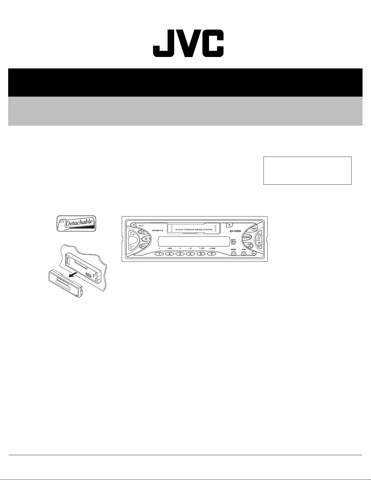
CASSETTE RECEIVER
MA10420048
KS-FX555
Area suffix
UN ----------------------------- Asean
TABLE OF CONTENTS
1 PRECAUTION. . . . . . . . . . . . . . . . . . . . . . . . . . . . . . . . . . . . . . . . . . . . . . . . . . . . . . . . . . . . . . . . . . . . . . . . . 1-3
2 SPECIFIC SERVICE INSTRUCTIONS . . . . . . . . . . . . . . . . . . . . . . . . . . . . . . . . . . . . . . . . . . . . . . . . . . . . . . 1-4
3 DISASSEMBLY . . . . . . . . . . . . . . . . . . . . . . . . . . . . . . . . . . . . . . . . . . . . . . . . . . . . . . . . . . . . . . . . . . . . . . . 1-5
4 ADJUSTMENT . . . . . . . . . . . . . . . . . . . . . . . . . . . . . . . . . . . . . . . . . . . . . . . . . . . . . . . . . . . . . . . . . . . . . . . 1-19
5 TROUBLESHOOTING . . . . . . . . . . . . . . . . . . . . . . . . . . . . . . . . . . . . . . . . . . . . . . . . . . . . . . . . . . . . . . . . . 1-23
COPYRIGHT © 2004 Victor Company of Japan, Limited
No.MA104
2004/8
Page 2
SPECIFICATION
AUDIO AMPLIFIER SECTION
Maximum Power Output Front 45 W per channel
Rear 45 W per channel
Continuous Power Output (RMS) Front 17 W per channel into 4 Ω, 40 Hz to 20 000 Hz at no more than 0.8%
total harmonic distortion.
Rear 17 W per channel into 4 Ω, 40 Hz to 20 000 Hz at no more than 0.8%
total harmonic distortion.
Load Impedance 4 Ω (4 Ω to 8 Ω allowance)
Tone Control Range Bass ±10 dB at 100 Hz
Treble ±10 dB at 10 kHz
Frequency Response 40 Hz to 20 000 Hz
Line-Out Level/Impedance 2.0 V/20 kΩ load (250 nWb/m)
TUNER SECTION
Frequency Range FM 87.5 MHz to 108.0 MHz
AM 531 kHz to 1 602 kHz
[FM Tuner] Usable Sensitivity 11.3 dBf (1.0 µV/75 Ω)
Stereo Separation 30 dB
[AM Tuner] Sensitivity 20 µV
Selectivity 35 dB
CASSETTE DECK SECTION
Wow & Flutter 0.11% (WRMS)
Frequency Response 30 Hz to 16 000 Hz (Normal tape)
GENERAL
Power Requirement Operating Voltage DC 14.4 V (11 V to 16 V allowance)
Grounding System Negative ground
Allowable Operating Temperature 0ºC to +40ºC
Dimensions (W × H × D) Installation Size (approx.) 178 mm × 50 mm × 150 mm
Panel Size (approx.) 170 mm × 46 mm × 19 mm
Mass (approx.) 1.3 kg (excluding accessories)
Design and specifications are subject to change without notice.
1-2 (No.MA104)
Page 3

1.1 Safety Precautions
SECTION 1
PRECAUTION
!
Burrs formed during molding may be left over on some parts of the chassis. Therefore,
pay attention to such burrs in the case of preforming repair of this system.
(No.MA104)1-3
Page 4

SECTION 2
SPECIFIC SERVICE INSTRUCTIONS
This service manual does not describe SPECIFIC SERVICE INSTRUCTIONS.
1-4 (No.MA104)
Page 5
SECTION 3
DISASSEMBLY
3.1 Main body
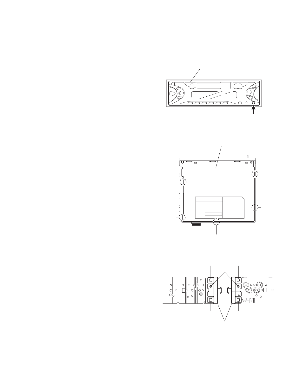
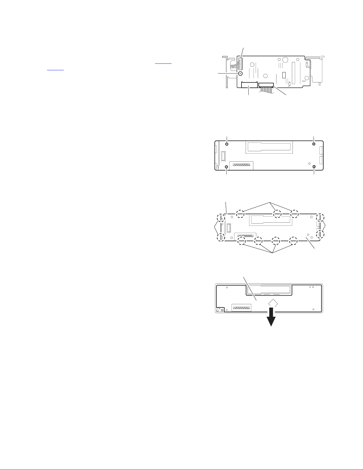
3.1.1 Removing the front panel assembly
(See Fig.1)
(1) Press the release button and remove the front panel as-
sembly.
3.1.2 Removing the bottom cover
(See Fig.2)
• Prior to performing the following procedure, remove the front
panel assembly.
(1) Turn the body upside down.
(2) Insert a screwdriver under the joints to release the two
joints a on the left side, the two joints b on the right side and
the joint c on the back of the body, then remove the bottom
cover from the body.
CAUTION:
When releasing the joint c using a screwdriver, do not damage
the main board.
Joint a
Front panel assembly
Fig.1
Bottom cover
Release button
Joint
b
3.1.3 Removing the front chassis
(See Fig.3)
• Prior to performing the following procedure, remove the front
panel assembly and bottom cover.
(1) Remove the screw A on each side of the body.
(2) Release the two joints d and the two joints e on the sides,
then remove the front chassis toward the front.
Joint a
Joint c
Fig.2
Joint d Joint e
A
Joint d
Front chassis assembly
Fig.3
Joint e
Joint b
(No.MA104)1-5
Page 6
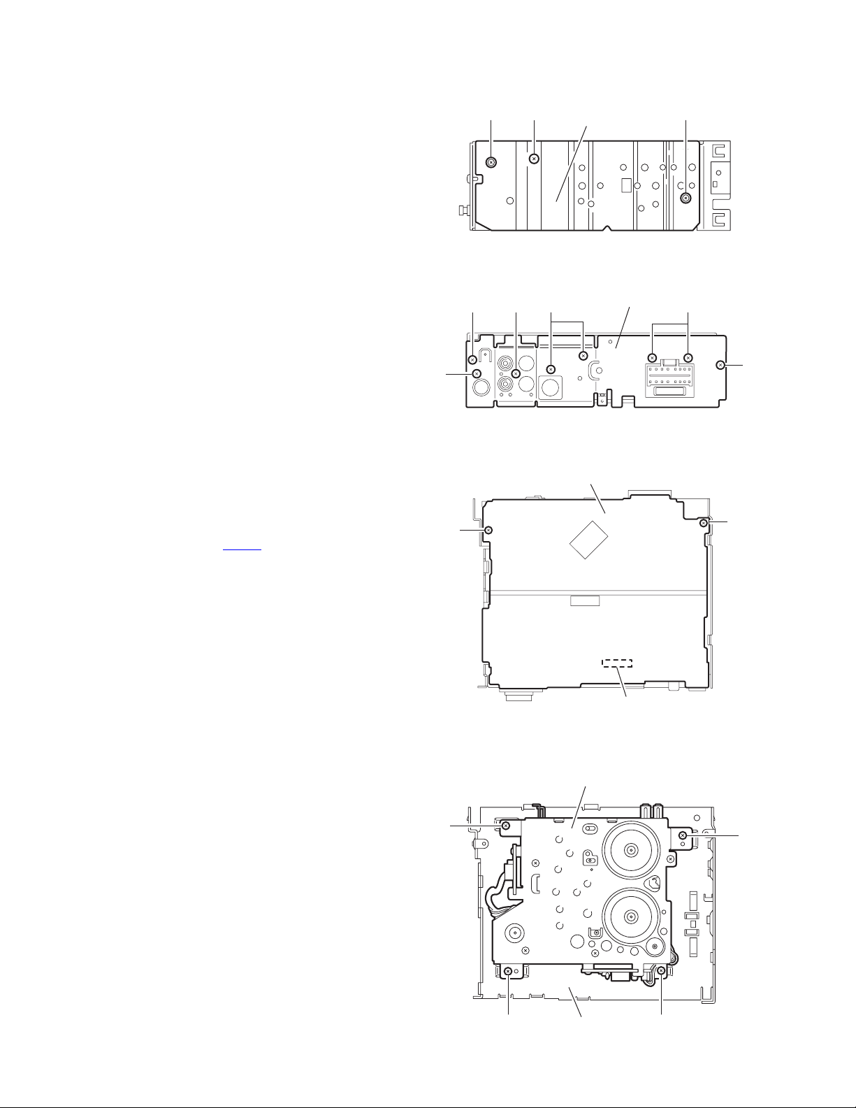
3.1.4 Removing the heat sink
(See Fig.4)
• Prior to performing the following procedure, remove the front
panel assembly.
(1) Remove the screw B and two screws C attaching the heat
sink on the left side of the body, and remove the heat sink.
3.1.5 Removing the rear panel
(See Fig.5 )
• Prior to performing the following procedure, remove the front
panel assembly and bottom cover.
(1) Remove the two screws D, three screws E and three
screws F attaching the rear panel on the back of the body.
D
C
B
Heat sink
Fig.4
EFF
Rear panel
C
3.1.6 Removing the main board
(See Fig.6)
• Prior to performing the following procedure, remove the front
panel assembly, bottom cover, front chassis, heat sink and
rear panel.
(1) Remove the two screws G attaching the main board on the
top chassis.
(2) Disconnect the connectors CP701
the cassette mechanism assembly.
3.1.7 Removing the cassette mechanism assembly
(See Fig.7)
• Prior to performing the following procedure, remove the front
panel assembly, bottom cover, front chassis, heat sink, rear
panel and main board.
(1) Remove the four screws H attaching the cassette mecha-
nism assembly from the top chassis.
on the main board from
E
H
G
D
Fig.5
Main board
G
CP701
Fig.6
Cassette mechanism assembly
H
1-6 (No.MA104)
H
Top chassis
Fig.7
H
Page 7
3.1.8 Removing the mecha board
f
(See Fig.8)
• Prior to performing the following procedure, remove the front
panel assembly, bottom cover, front chassis, heat sink, rear
panel, main board and cassette mechanism assembly.
(1) Disconnect the wire from the connectors CN402
on the mecha board.
CN403
(2) Remove the screw J attaching the mecha board.
and
CN402
J
3.1.9 Removing the front board
(See Figs.9 to 11)
• Prior to performing the following procedure, remove the front
panel assembly.
(1) Remove the four screws K attaching the rear cover on the
back of the front panel assembly. (See fig.9)
(2) Release the eleven joints f, the front panel and the rear
cover become separate. (See fig.10)
(3) Remove the front board from the front panel assembly.
(See fig.11)
Caution:
Take care not to lose the springs.
CN401
K
K K
Front panel assembly
Joint f
LCD & Key control board
Fig.8
Fig.9
Joint f
Joint f
Fig.10
CN403
K
Joint
Rear cover
Fig.11
(No.MA104)1-7
Page 8
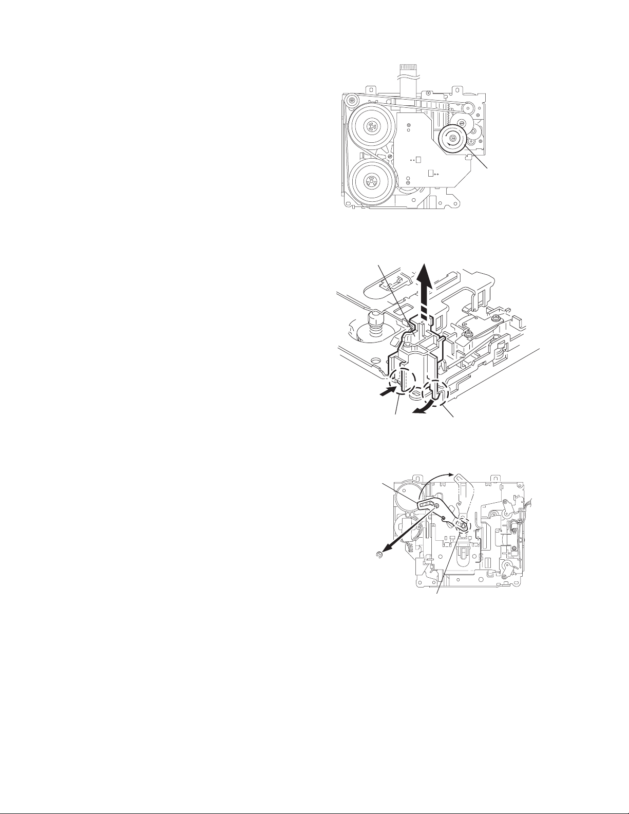
3.2 Cassette mechanism assembly
r
REFERENCE:
Prior to performing the following procedures, turn the mode
gear on the bottom of the body until the respective part comes
to the EJECT position (Refer to Fig.1).
3.2.1 Removing the cassette guide
(See Fig.2)
(1) Turn the mode gear to set to RVS play or subsequent
mode.
(2) Remove the cassette guide from the main chassis while re-
leasing each two joint tabs a in the direction of the arrow.
Mode gea
Fig.1
Cassette guide
3.2.2 Removing the load arm
(See Fig.3)
(1) Remove the E-washer attaching the load arm.
(2) Move the load arm in the direction of the arrow and release
the joint b on the cassette catch.
Load arm
E-washer
Tab a
Tab a
Fig.2
Joint b
Fig.3
1-8 (No.MA104)
Page 9

3.2.3 Removing the cassette hanger assembly / cassette holder
r
(See Fig.4 to 7)
(1) Check the mode is set to EJECT. Push down the front part
of the cassette holder and move in the direction of the arrow to release the joint c.
(2) Move the rear part of the cassette hanger assembly in the
direction of the arrow to release it from the two joint bosses
d.
(3) Release the holder stabilizer spring from the hooks e and
f, then pull out from the cassette hanger assembly.
(4) Bring up the rear side of the cassette hanger assembly to
release the joint g and h.
(5) Pull out the cassette catch from the cassette hanger as-
sembly.
Cassette holder assembly
Side bracket
Joints c
Cassette holder assembly
Fig.4
Boss d
Cassette hanger
assembly
Boss d
Cassette stabilizer spring
Hook e
Cassette holder
assembly
Hook g
Cassette hange
assembly
Hook f
Fig.5
Cassette hanger
assembly
Hook h
Fig.6
Cassette hanger assembly
Cassette catch
Cassette holder assembly
Fig.7
(No.MA104)1-9
Page 10

3.2.4 Removing the side bracket assembly
(See Fig.8 to 10)
(1) Remove the screw A attaching the side bracket assembly.
(2) Detach the front side of the side bracket assembly upward
and pull out forward to release the joint i and j in the rear.
CAUTION:
When reassembling, make sure that the boss k of the
main chassis is set in the notch of the load rack under the
side bracket assembly. Do not reattach the load rack on
the boss k.
CAUTION:
After reattaching the side bracket assembly, confirm operation.
Side bracket assembly
Joint i
Joint j
A
Side bracket assembly
Fig.8
Side bracket assembly
Joint i
Joint j
Load rack
Load rack
Boss k
Fig.9
Boss k
1-10 (No.MA104)
Fig.10
Page 11

3.2.5 Removing the pinch arm (F) assembly
r
(See Fig.11 and 12)
(1) Remove the polywasher and pull out the pinch arm (F) as-
sembly.
(2) Remove the compulsion spring.
3.2.6 Removing the pinch arm (R) assembly
(See Fig.11 and 12)
(1) Remove the polywasher and pull out the pinch arm (R) as-
sembly.
3.2.7 Removing the slide chassis assembly
(See Fig.13 and 14)
REFERENCE:
It is not necessary to remove the head and the tape guide.
(1) Move the slide chassis assembly in the direction of the ar-
row to release the two joints l and remove from the main
chassis.
(2) Remove the rack link.
CAUTION:
When reassembling, first reattach the rack link, and next
fit the boss m and hook n of the slide chassis assembly
to the hole of the main chassis, and engage the two joints
l.
Joint l
Joint l
Slide chassis assembly
Fig.13
Head
Tape guide
Boss m
Rack link
Hook n
Polywasher
Polywasher
Compulsion
spring
Pinch arm
(R) assembly
Pinch arm
(F) assembly
Fig.11
Pinch arm (F) assembly
Pinch arm
(R) assembly
Polywashe
Fig.14
Polywasher
Fig.12
(No.MA104)1-11
Page 12

3.2.8 Removing the head / tape guide
(See Fig.16 and 17)
REFERENCE:
It is not necessary to remove the slide chassis assembly.
(1) Remove the band attaching the wire to the head.
(2) Remove the two screws B, the head and the head support
spring.
(3) Remove the pinch arm spring from the tape guide.
(4) Remove the tape guide and the pinch spring arm.
CAUTION:
When reattaching the pinch arm spring, set both end of
it to the pinch spring arm (remarked o).
CAUTION:
When reattaching the head, set the wires into the groove
of the tape guide (Fig.16).
3.2.9 Removing the flywheel assembly (F) & (R)
(See Fig.18 and 19)
REFERENCE:
It is not necessary to remove the slide chassis assembly.
(1) Remove the belt at the bottom.
(2) Remove the two polywashers on the upper side.
(3) Pull out each flywheel assembly downward.
B
Slide chassis assembly
Flywheel assembly (F)
Flywheel assembly (R)
Belt
Fig.17
Polywasher
Polywasher
Head
Head support spring
Tape guide
o
Pinch spring arm
Head
Fig.15
Tape guide
B
Pinch arm spring
Flywheel assembly (F)
Flywheel assembly (R)
Fig.18
o
1-12 (No.MA104)
Slid chassis assembly
Fig.16
Page 13

3.2.10 Disassembling the flywheel assembly (F)
r
(See Fig.19 and 20)
(1) Push and turn counterclockwise the spring holder (F) to re-
lease the three joints p on the bottom of the flywheel.
(2) The spring holder (F), the TU spring and the friction gear
play come off.
(3) Remove the polywasher and felt.
3.2.11 Disassembling the flywheel assembly (R)
(See Fig.19 and 20)
(1) Push and turn clockwise the spring holder (R) to release
the three joints q on the bottom of the flywheel.
(2) The spring holder (R), the FF spring and the friction gear
FF come off.
(3) Remove the polywasher and the felt.
3.2.12 Removing the reel board
(See Fig.21 and 22)
(1) Remove the two screws C attaching the reel board.
(2) Move the reel board in the direction of the arrow to release
the joint r.
(3) Unsolder the wires if necessary.
CAUTION:
When reattaching, confirm operation of the MODE
switch and the ST-BY switch.The mode position between EJECT and ST-BY is optimum for reattaching.Connect the card wire extending from the reel board
to the FFC pad before reattaching the reel board.
FFC pad
C
Joint
Reel board
C
Fig.21
FFC pad
CT-1 switch
MODE switch
Flywheel
assembly (F)
Joint p
Joints p
Fig.19
Polywasher
Spring holder (R)
Spring holder (F)
TU spring
Friction gear FF
Friction gear play
Polywasher
FF spring
Flywheel
assembly (R)
Joints q
Joint q
Soldering
ST-BY switch
Fig.22
Felt
Flywheel assembly (F)
Fig.20
Felt
Flywheel assembly (R)
(No.MA104)1-13
Page 14

3.2.13 Removing the gear base arm / gear base link assembly
(See Fig.23 to 25)
(1) Move the gear base arm in the direction of the arrow.
(2) Insert a slotted screwdriver to the gear base spring under
the gear base arm, and release the gear base arm upward
from the boss on the gear base assembly.
(3) Remove the gear base arm from the main chassis while re-
leasing the two joints s.
(4) Move the gear base link assemby in the direction of the ar-
row to release the two joints t.
REFERENCE:
When reattaching the gear base arm, make sure that the
boss on the gear base assembly is inside the gear base
spring.
3.2.14 Removing the FFC pad
(See Fig.25 and 27)
(1) Push each joint hook u of the FFC pad and remove toward
the bottom.
Gear base
link assembly
Gear base spring
Joint t
Joint t
Gear base arm
Joints s
Hook u
FFC pad
Hook u
Fig.23
Gear base arm
Gear base link
assembly
Screwdriver
Fig.24
Gear base arm
1-14 (No.MA104)
FFC pad
Fig.25
Page 15

3.2.15 Removing the mode gear
r
r
(See Fig.26 and 29)
(1) Remove the polywasher on the bottom and pull out the
mode gear.
3.2.16 Removing the mode switch actuator
(See Fig.26, 27 and 29)
(1) Pull out the mode switch actuator at the bottom.
REFERENCE:
When reattaching the mode switch actuator to the main
chassis, make sure to set on the shaft and insert v into
the slot w.
3.2.17 Removing the direction link / direction plate
(See Fig.27 to 29)
(1) Remove the polywasher attaching the direction link.
(2) Bring up the direction link to release the three joints x, y
and z at a time.
(3) Move the direction plate in the direction of the arrow to re-
lease the two joints a’.
REFERENCE:
When reattaching the direction plate, engage the two
joints a’ and move in the direction of the arrow (Refer to
Fig.28).
REFERENCE:
When reattaching the direction link, move the direction
plate in the direction of the arrow and engage the three
joint x, y and z at a time (Refer to Fig.29).
3.2.18 Removing the mode rack assembly
(See Fig.27 and 28)
(1) Move the mode rack assembly in the direction of the arrow
to release the two joints b’ and the joint c’.
REFERENCE:
When reattaching, set the two b’ on the bottom of the
mode rack assembly into the slots of the main chassis
and move in the direction of the arrow (See Fig.28).
Direction plate
Direction plate
Joints a'
Joint z
Direction link
Direction plate
Mode switch actuator
Direction link
Fig.26
Slot w
Joint y
Polywasher
Fig.27
Mode rack assembly
Joint b'
Mode gear
Polywashe
Mode rack assembly
Joint x
Joint b'
Joint c'
Joints a'
Fig.28
Direction link
Mode switch actuator
Polywasher
v
Mode gea
Direction plate
Mode rack assembly
Fig.29
(No.MA104)1-15
Page 16

3.2.19 Removing the gear base assembly / take up gear / reflector gear
r
(See Fig.30 to 32)
(1) Push in the pin d’ of the gear base assembly on the upper
side of the body and move the reflector gear toward the
bottom, then pull out.
(2) Remove the polywasher on the bottom and pull out the
take up gear.
(3) Move the gear base assembly in the direction of the arrow
to release it from the two slots e’ of the main chassis.
REFERENCE:
The parts are damaged when removed. Please replace
with new ones.
3.2.20 Removing the reel driver / reel spindle
(See Fig.32)
(1) Draw out the reel driver from the shaft on the main chassis
and remove the reel driver spring and the reel spindle respectively.
CAUTION:
The reel driver is damaged when removed. Please replace with a new one.
Gear base assembly
Pin d'
Polywasher
Slot e'
Slot e'
Fig.30
Take up gear
Reflector gear
Reel driver
Reel driver spring
Reel spindle
Main chassis
Reflector gear
Fig.31
Reel driver
Reel driver spring
Reel spindle
Gear base assembly
Slots e’
Take up gea
Polywasher
Fig.32
1-16 (No.MA104)
Page 17

3.2.21 Removing the side bracket assembly
(See Fig.33 to 37)
(1) Remove the eject cam plate spring.
(2) Push the joint f’ through the slot to remove the load rack
downward.
(3) Move the eject cam limiter in the direction of the arrow to
release it from the boss g’ of the side bracket assembly and
from the two joints h’.
(4) Move the eject cam plate in the direction of the arrow to re-
lease the joint i’.
CAUTION:
When reassembling, confirm operation of each part before reattaching the eject cam plate spring.
Joint f'
Side bracket assembly
Boss g'
Eject cam plate
Fig.36
Side bracket assembly
Joint i'
Eject cam plate spring
Side bracket assembly
Joint h'
Side bracket
assembly
Boss g'
Boss g'
Load rack
Fig.33
Eject cam limiter
Joint f'
Fig.34
Eject cam limiter
Eject cam plate
Joint i'
Fig.37
Joint h'
Load rack
Joint h'
Eject cam plate
Fig.35
Joint h'
(No.MA104)1-17
Page 18

3.2.22 Removing the main motor assembly / sub motor assembly
r
r
r
(See Fig.38 to 40)
(1) Remove the belt at the bottom.
(2) Remove the polywasher and pull out the mode gear.
(3) Pull out the reduction gear (B).
(4) Remove the polywasher and pull out the reduction gear
(A).
(5) Remove the two screws attaching the main motor assem-
bly.
(6) Remove the two screws E attaching the sub motor assem-
bly.
(7) Unsolder the wires on the reel board if necessary.
CAUTION:
When reassembling, adjust the length of the wires extending from the sub motor asswmbly by attaching them
to the side of the sub motor assembly with the wires extending from the main motor assembly using a spacer.
Belt
Reduction gear (B)
Reduction gear (B)
E
Mode gear
Polywasher
Fig.38
Main motor
D
assembly
Reduction
gear (A)
Polywashe
Sub moto
assembly
E
Polywasher
Reduction gear (A)
D
Spacer
Main motor assembly
Sub motor assembly
Fig.39
Main motor assembly
Sub motor assembly
Fig.40
Space
1-18 (No.MA104)
Page 19

SECTION 4
ADJUSTMENT
4.1 Adjustment method
Test instruments required for adjustment
(1) Digital oscilloscope (100MHz)
(2) Frequency counter meter
(3) Electric voltmeter
(4) Wow & flutter meter
(5) Test tapes
• VT724...........................For DOLBY level measurement
• VT739..............For playback frequency measurement
• VT712....For wow flutter & tape speed measurement
• VT703........................For head azimuth measurement
(6) Torque gauge............................Cassette type for CTG-N
Measuring conditions (Amplifier section)
Power supply voltage: DC14.4V (11V to 16V)
Load impedance: 4Ω (4Ω to 8Ω allowance)
Line out level/Impedance: 2.0V/20kΩ load (250 nWb/m)
Standard volume position
Balance and Bass, Treble volume, Fader : Center (Indication "0")
Loudness, Dolby NR, Sound, Cruise : Off
Volume position is about 2V at speaker output with following
conditions, Playback the test tape VT721.
AM mode 999kHz/62dB, INT/400Hz, 30%
modulation signal on receiving.
FM mono mode 97.9MHz/66dB, INT/400Hz, 22.5kHz
deviation pilot off mono
FM stereo mode 1kHz, 67.5kHz dev. pilot 7.5kHz dev.
Output level 0dB (1µV,50Ω/open terminal)
(No.MA104)1-19
Page 20

Information for using a car audio service jig
(1) We're advancing efforts to make our extension cords common for all car audio products.
Please use this type of extension cord as follows.
(2) As a U-shape type top cover is employed, this type of extension cord is needed to check operation of the mechanism assembly
after disassembly.
(3) Extension cord : EXTKSRT002-18P ( 18 pin extension cord ) For connection between mechanism assemblyand main board.
(4) Check for mechanism driving section such as motor ,etc.
Disassembly method
(1) Remove the front panel assembly.
(2) Remove the bottom cover.
(3) Remove the front chassis.
(4) Remove the rear panel
(5) Remove the heat sink.
(6) Remove the main board.
(7) Reattach the heat sink with the two screws B. (Refer to DISASSEMBLY.)
(8) Install the front chassis and front panel assembly.
(9) Confirm that current is being carried by connecting an extension cord jig.
NOTE:
Available to connect to the CJ701
CAUTION :
Be sure to attach the heat sink and rear panel on the power amplifier IC and regulator IC of a main board when supplying
the power.If voltage is applied without attaching those parts, the power amplifier IC and regulator IC will be destroyed
by heat.
connector when installing the front panel.
To
Cassette mechanism
EXTKSRT002-18P
Extension cord
EXTKSRT002-18P
To
Main board
Front panel assembly
Cassette mechanism
Main board
1-20 (No.MA104)
Page 21

Arrangement of adjusting & test points
A
Cassette mechanism
(Surface)
Motor assembly
Tape speed adjust
Azimuth screw
(Forward)
Playback head
Azimuth screw B
(Reverse)
Head section view
Azimuth screw B
(Reverse)
Playback head
Azimuth screw A
(Forward)
(No.MA104)1-21
Page 22

Item
Head
1.
azimuth
adjustment
Conditions
Test tape:
SCC-1659
VT703 (10kHz)
Test tape:
VT724 (1kHz)
VT703 (10kHz)
VT721 (315Hz)
Adjustment and Confirmation methods
Head height adjustment
Adjust the azimuth directly. When you
adjust the height using a mirror tape,
remove the cassette housing from the
mechanism chassis.
After installing thecassette housing,
perform the azimuth adjustment.
Load the SCC-1659 mirror tape. Adjust with
1.
height adjustment screw A and azimuth
adjustment screw B so that line A of the
mirror tape runs in the center between Lch
and Rch in the reverse play mode.
After switching from REV to FWD then to
2.
REV, check that the head position set in
procedure 1 is not changed. (If the position
has shifted, adjust again and check.)
Adjust with azimuth adjustment screw B so
3.
that line B of the mirror tape runs in the
center between Lch and Rch in the forward
play mode.
Head azimuth adjustment
Load VT724 (1kHz) and play it back in
1.
the reverse play mode.
Set the Rch output level to max.
Load VT703 (10kHz) and play it back in
2.
the forward play mode. Adjust the Rch
and Lch output levels to max, with
azimuth adjustment screw B. In this case,
the phase difference should be within 45 .
Engage the reverse mode and adjust the
3.
output level to max, with azimuth
adjustment screw C.
(The phase difference should be 45 or
more.)
When switching between forward and
4.
reverse modes, the difference between
channels should be within 3dB. (Between
FWD L and R, REV L and R.)
S.Values Adjust
A line
Head shield
The head is at low position
during.
B line
Head shield
The head is at High position
during REV.
Output
level:
Maximum
PBHead
FWD Adj B
REV Adj C
(0 ) (45 )
HEIGHT Adj A
phase
Tape speed
2.
and wow
flutter
confirmation
Play back
3.
frequency
response
confirmation
1-22 (No.MA104)
When VT721 (315Hz) is played back,
5.
the level difference between channels
should be within 1.5dB.
Test tape: VT712
(3kHz)
Test tape: VT724
(1kHz)
VT739
(63Hz / 1kHz / 10kHz)
The tuner section is of an adjustment-freedesign. In case the tuner is in trouble, replace the tuner pack.
Check to see if the reading of the F, counter /
1.
wow flutter meter is within 3015Hz to 3045Hz
(FWD/ REV), and less than 0.35% (JIS RMS).
In case of out of specification, adjust the
2.
motor with a built-in volume resistor.
Play test tape VT724, and set the volume
1.
position at 2V.
Play test tape VT739 and confirm.
2.
1kHz / 10kHz: -1 3dB,
1kHz / 63Hz: 0 3dB,
When 10kHz is out of specification, it will be
3.
necessary to read adjust the azimuth.
Tape speed:
3015Hz
to 3045Hz
Wow
flutter: less
than 0.35%
Speaker out
1kHz / 63Hz
: 0 3dB
1kHz / 10kHz
: -1 3dB
Built-in volume
resistor
Page 23

5.1 16 PIN CORD DIAGRAM
SECTION 5
TROUBLESHOOTING
BK
8
RD
7
NC
6
BL/WH
5
WH
4
GN
3
GY
1
VI
2
YL
OR/WH
NC
NC
WH/BK
GN/BK
GY/BK
VI/BK
8BK
16 YL
RD
7
OR/WH
15
BL/WH
5
4
WH
16
15
14
13
12
11
10
BK
RD
BL
WH
Black
Red
Blue
White
GN
VI
GY
YL
OR
Green
Violet
Gray
Yellow
Orange
9
GND
MEMORY
ACC
ILL
REMOTE
FL+
20
10
2
9
1
8
RR
FR
FL
RL
WH/BK
12
GN
3
GN/BK
11
VI
2
10 VI/BK
1
GY
9 GY/BK
Rear Right
Front Right
Front Left
Rear Left
REMOTE
ACC
MEMORY
GND
Illuminations Control
ILL
FL-
RL+
RL-
RR+
RR-
FR+
FR-
Remote out
ACC Line
Memory Backup Battery +
Ground
18
6
16
5
15
7
17
20
12
19
18
17
16
15
14
13
11
BK
NC
WH/BK
GY/BK
GN/BK
VI/BK
NC
NC
NC
NC
YL
OR/WH
WH
GY
GN
VI
NC
NC
RD
BL/WH
10
9
8
7
6
5
4
3
2
1
(No.MA104)1-23
Page 24

Victor Company of Japan, Limited
AV & MULTIMEDIA COMPANY CAR ELECTRONICS CATEGORY 10-1,1chome,Ohwatari-machi,Maebashi-city,371-8543,Japan
(No.MA104)
Printed in Japan
WPC
 Loading...