

Page 1
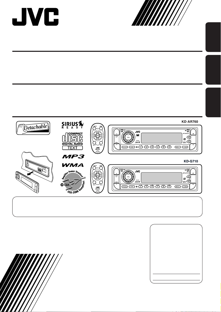
CD RECEIVER KD-AR760/KD-G710
RECEPTOR CON CD KD-AR760/KD-G710
ENGLISHESPAÑOL
RECEPTEUR CD KD-AR760/KD-G710
For canceling the display demonstration, see page 8.
Para cancelar la demostración en pantalla, consulte la página 8.
Pour annuler la démonstration des affichages, référez-vous à la page 8.
For installation and connections, refer to the separate manual.
Para la instalación y las conexiones, refiérase al manual separado.
Pour l’installation et les raccordements, se référer au manuel séparé.
INSTRUCTIONS
MANUAL DE INSTRUCCIONES
MANUEL D’INSTRUCTIONS
For customer Use:
Enter below the Model
No. and Serial No. which
are located on the top or
bottom of the cabinet.
Retain this information for
future reference.
Model No.
Serial No.
FRANÇAIS
GET0247-001A
[J]
Page 2
Thank you for purchasing a JVC product.
Please read all instructions carefully before operation, to ensure your complete understanding and to
obtain the best possible performance from the unit.
ENGLISH
INFORMATION (For U.S.A.)
This equipment has been tested and found to comply with the limits for a Class B digital device,
pursuant to Part 15 of the FCC Rules. These limits are designed to provide reasonable protection
against harmful interference in a residential installation. This equipment generates, uses, and can
radiate radio frequency energy and, if not installed and used in accordance with the instructions,
may cause harmful interference to radio communications. However, there is no guarantee that
interference will not occur in a particular installation. If this equipment does cause harmful
interference to radio or television reception, which can be determined by turning the equipment
off and on, the user is encouraged to try to correct the interference by one or more of the
following measures:
– Reorient or relocate the receiving antenna.
– Increase the separation between the equipment and receiver.
– Connect the equipment into an outlet on a circuit different from that to which the receiver is
connected.
– Consult the dealer or an experienced radio/TV technician for help.
IMPORTANT FOR LASER PRODUCTS
1. CLASS 1 LASER PRODUCT
2. CAUTION : Do not open the top cover. There are no user serviceable parts inside the unit; leave
all servicing to qualified service personnel.
3. CAUTION : Visible and invisible laser radiation when open and interlock failed or defeated.
Avoid direct exposure to beam.
Warning:
If you need to operate the receiver while
driving, be sure to look ahead carefully or
you may be involved in a traffic accident.
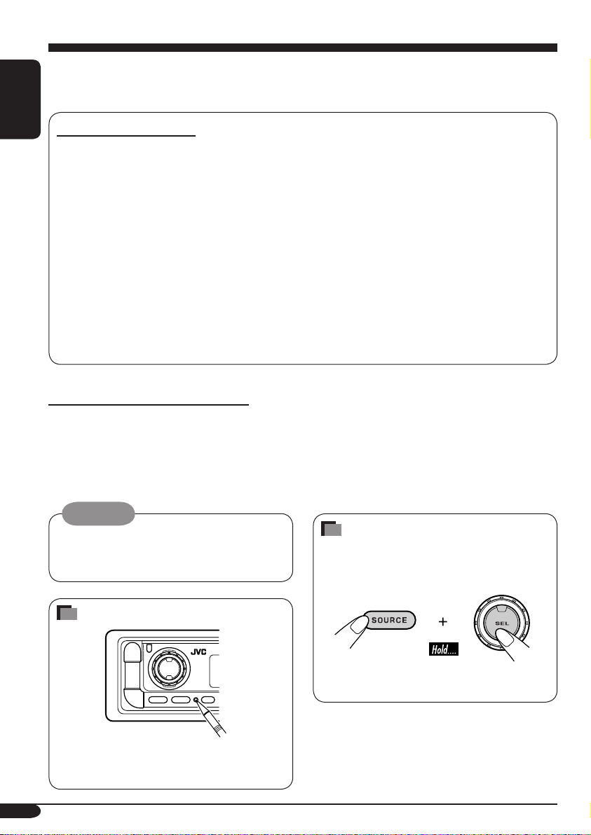
How to reset your unit
This will reset the microcomputer. Your
preset adjustments will also be erased.
2
How to forcibly eject a disc
If a disc cannot be recognized by the
receiver or cannot be ejected, ejects the disc
as follows.
If this does not work, try to reset your
receiver.
Page 3
Contents
How to reset your unit ........................... 2
How to forcibly eject a disc................... 2
How to read this manual........................ 4
How to use the MODE button ............... 4
Control panel
—
KD-AR760/KD-G710 .............. 5
Parts identification................................. 5
Remote controller — RM-RK50
Main elements and features ................... 6
... 6
Getting started....................... 7
Basic operations.................................. 7
Canceling the display demonstrations ... 8
Setting the clock .................................... 8
Radio operations ................... 9
Listening to the radio........................... 9
Storing stations in memory.................... 10
Listening to a preset station ................... 10
Disc operations ...................... 11
Playing a disc in the receiver ............... 11
Playing discs in the CD changer ........... 12
Other main functions ............................. 14
Changing the display information ......... 15
Selecting the playback modes................ 16
Sound adjustments ................ 17
Selecting preset sound modes
(iEQ: intelligent equalizer) ................ 17
Adjusting the sound ............................... 18
Storing your own sound adjustments..... 19
General settings — PSM ......... 20
Basic procedure ..................................... 20
Other main functions ............. 23
Assigning titles to the sources ............... 23
Changing the control panel angle .......... 24
Detaching the control panel................... 24
External component operations
... 25
Playing an external component ............ 25
SIRIUS® radio operations
............ 26
Listening to the SIRIUS® radio.............. 27
Storing channels in memory .................. 28
Listening to a preset channel ................. 28
Maintenance .......................... 29
More about this receiver ........ 30
Troubleshooting ..................... 32
Specifications ......................... 35
ENGLISH
Caution on volume setting:
Discs produce very little noise compared
with other sources. Lower the volume
before playing a disc to avoid damaging
the speakers by the sudden increase of the
output level.
*For safety....
• Do not raise the volume level too much, as
this will block outside sounds, making driving
dangerous.
• Stop the car before performing any
complicated operations.
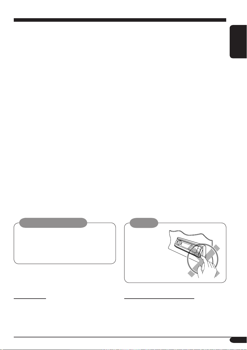
Caution:
Do not insert your
finger behind the
control panel.
*Temperature inside the car....
If you have parked the car for a long time in
hot or cold weather, wait until the temperature
in the car becomes normal before operating the
unit.
3
Page 4
How to read this manual
The following methods are used to made the
explanations simple and easy-to-understand:
• Some related tips and notes are explained in
ENGLISH
“More about this receiver” (see page 30).
• Button operations are mainly explained with
the illustrations as follows:
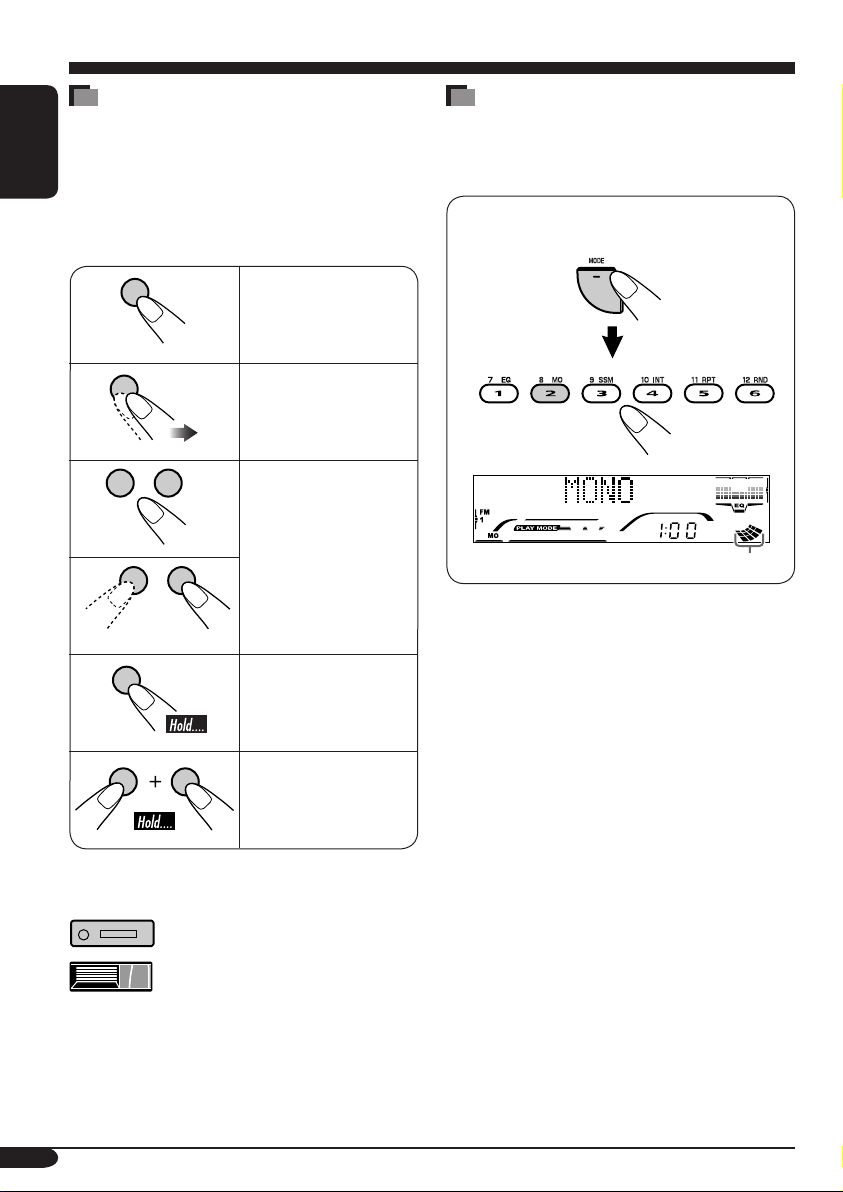
Press briefly.
Press repeatedly.
How to use the MODE button
If you press MODE, the receiver goes into
functions mode, then the number buttons and
5/∞ buttons work as different function buttons.
Ex.: When number button 2 works as
MO (monaural) button.
Press either one.
Press and hold until
your desired response
begins.
Press and hold both
buttons at the same
time.
The following marks are used to indicate...
: Built-in CD player operations.
: External CD changer operations.
Time countdown indicator
To use these buttons for original functions
again after pressing MODE, wait for
5 seconds without pressing any of these buttons
until the functions mode is cleared.
• Pressing MODE again also clears the
functions mode.
4
Page 5
Control panel — KD-AR760/KD-G710
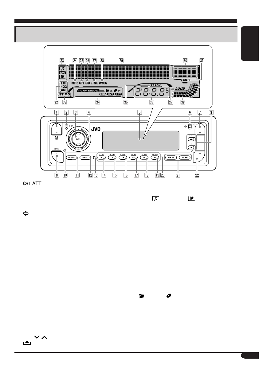
Parts identification
Display window
1 (standby/on attenuator) button
2 DISP (display) button
3 SEL (select) button
4 Control dial
5 Display window
6
(angle) button
7 0 (eject) button
8 5 (up) button / +10 button
∞ (down) button / –10 button
9 MODE button
p Remote sensor
• DO NOT expose the remote sensor to
strong light (direct sunlight or artificial
lighting).
q SOURCE button
w BAND button
e Reset button
r EQ (equalizer) button
t MO (monaural) button
y SSM (Strong-station Sequential Memory)
button
u INT (intro) button
i RPT (repeat) button
o RND (random) button
; Number buttons
a 4
s
/ ¢ buttons
(control panel release) button
Display window
d Disc information indicators—TAG (ID3
Tag),
f MP3 indicator
g CH (CD changer) indicator
• Lights up only when CD-CH is selected
h CD indicator
j LINE indicator —Only for KD-AR760
k WMA indicator
l Main display
/ Equalizer pattern indicator
Audio level indicator
z EQ (equalizer) indicator
x Band indicators—FM1, FM2, FM3, AM
c Tuner reception indicators—ST (stereo),
MO (monaural)
v Playback mode / item indicators—
INT (intro), RPT (repeat)
b TRACK indicator
n Source / clock display
m LOUD (loudness) indicator
, Audio level indicator / Volume level
indicator
(track/file), (folder)
for the playback source.
(folder), (disc), RND (random),
ENGLISH
5
Page 6
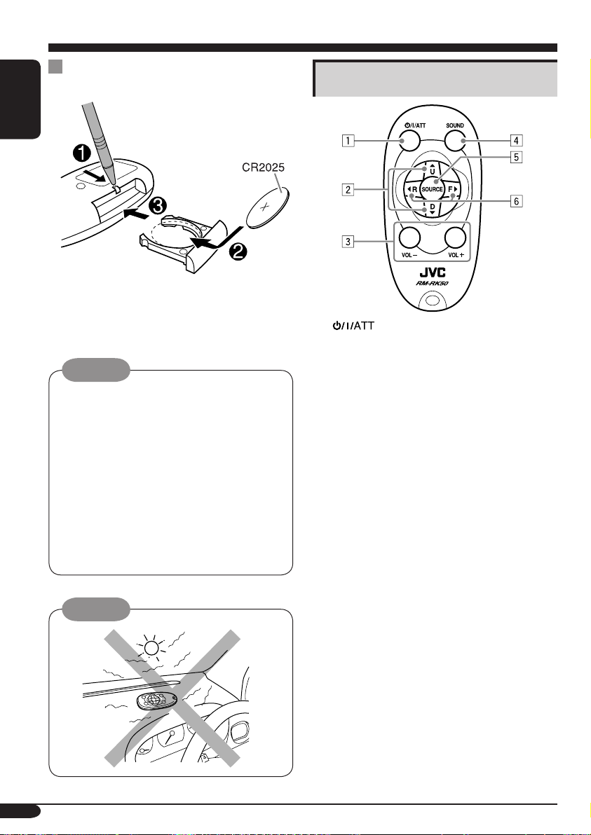
Remote controller — RM-RK50
Installing the lithium coin battery
(CR2025)
ENGLISH
• When operating, aim the remote controller
directly at the remote sensor on the
receiver. Make sure there is no obstacle in
between.
Warning:
• Store the battery in a place where children
cannot reach to avoid risk of accident.
• To prevent the battery from over-heating,
cracking, or starting a fire:
– Do not recharge, short, disassemble, or
heat the battery or dispose of it in a fire.
– Do not leave the battery with other
metallic materials.
– Do not poke the battery with tweezers or
similar tools.
– Wrap the battery with tape and insulate
when throwing away or saving it.
Caution:
Main elements and features
1 (standby/on/attenuator) button
• Turns on and off the power and also
attenuates the sound.
2 5 U (up) / D (down) ∞ buttons
• 5 U: Changes the FM/AM bands.
• D ∞: Changes the preset stations.
• Changes the folder on the MP3/WMA
discs.
• While playing an MP3 disc on an
MP3-compatible CD changer:
– Changes the disc if pressed briefly.
– Changes the folder if pressed and held.
• While listening to the SIRIUS radio:
– Changes the categories.
3 VOL – / VOL + buttons
• Adjusts the volume level.
4 SOUND button
• Selects the sound mode (iEQ: intelligent
equalizer).
5 SOURCE button
• Selects the source.
6 2 R (reverse) / F (forward) 3 buttons
• Searches for stations if pressed briefly.
• Fast-forwards or reverses the track if
pressed and held.
• Changes the tracks on the disc.
• While listening to the SIRIUS radio:
– Changes the channels if pressed briefly.
– Changes the channels rapidly if pressed
and held.
6
Page 7
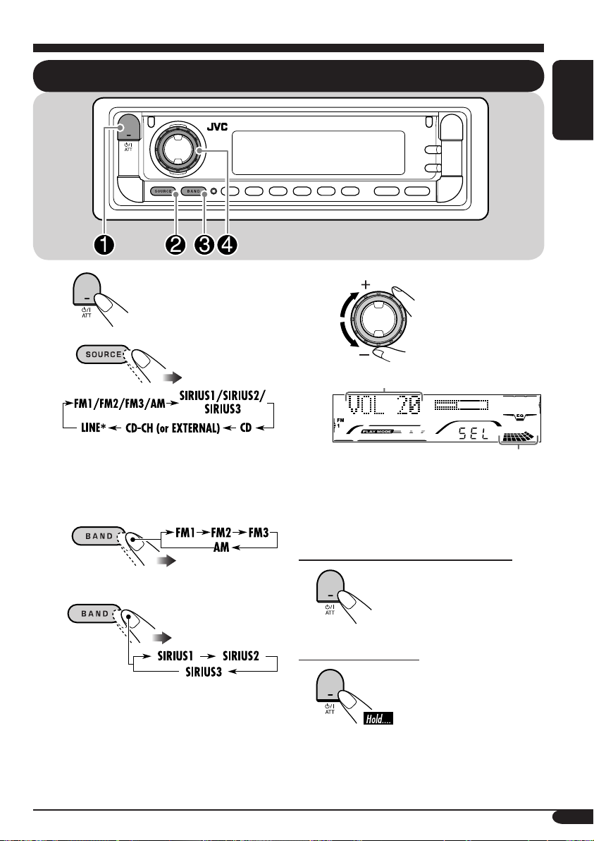
Getting started
Basic operations
ENGLISH
~
Ÿ
You cannot select some sources if they
are not ready.
* Only for KD-AR760.
! • For FM/AM tuner only
• For SIRIUS
®
radio only
⁄
Volume level appears.
Volume level indicator
@ Adjust the sound as you want.
(See pages 17 – 19.)
To drop the volume in a moment (ATT)
To restore the sound,
press it again.
To turn off the power
7
Page 8

Canceling the display
demonstrations
ENGLISH
If no operations are done for about 20 seconds,
display demonstration starts.
[Initial: DEMO ON] —see page 20.
Setting the clock
1
1
2
3
4
Finish the procedure.
2 Set the hour and minute.
1 Select “CLOCK HOUR,” then
adjust the hour.
2 Select “CLOCK MINUTE,” then
adjust the minute.
3 Finish the procedure.
To check the current clock time when the
power is turned off
To activate the display demonstration
In step 3 above...
8
Page 9
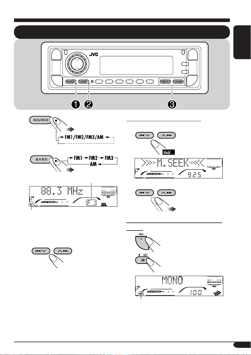
Radio operations
Listening to the radio
ENGLISH
~
Ÿ
Selected band appears.
Lights up when receiving an FM stereo
broadcast with sufficient signal strength.
! Start searching for a station.
When a station is received, searching
stops.
To stop searching, press the same
button again.
To tune in to a station manually
In step Ÿ on the left...
1
2 Select the desired station frequencies.
When an FM stereo broadcast is hard to
receive
1
2
Lights up when monaural mode is activated.
Reception improves, but stereo effect will
be lost.
To restore the stereo effect, repeat the same
procedure so that the MO indicator goes off.
9
Page 10
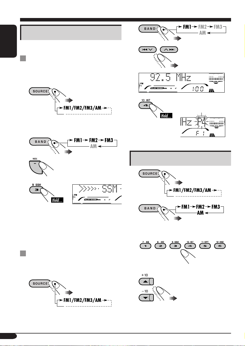
Storing stations in memory
2
You can preset six stations for each band.
ENGLISH
FM station automatic presetting —
SSM (Strong-station Sequential
Memory)
1
2 Select the FM band (FM1 – FM3)
you want to store into.
3
4
“SSM” appears, then disappears when
automatic presetting is over.
3
4 Preset number flashes
for a while.
Listening to a preset station
1
2
Local FM stations with the strongest signals are
searched and stored automatically in the FM
band.
Manual presetting
Ex.: Storing FM station of 92.5 MHz into the
preset number 4 of the FM1 band.
1
10
3 Select the preset station (1 – 6) you
want.
or
Page 11
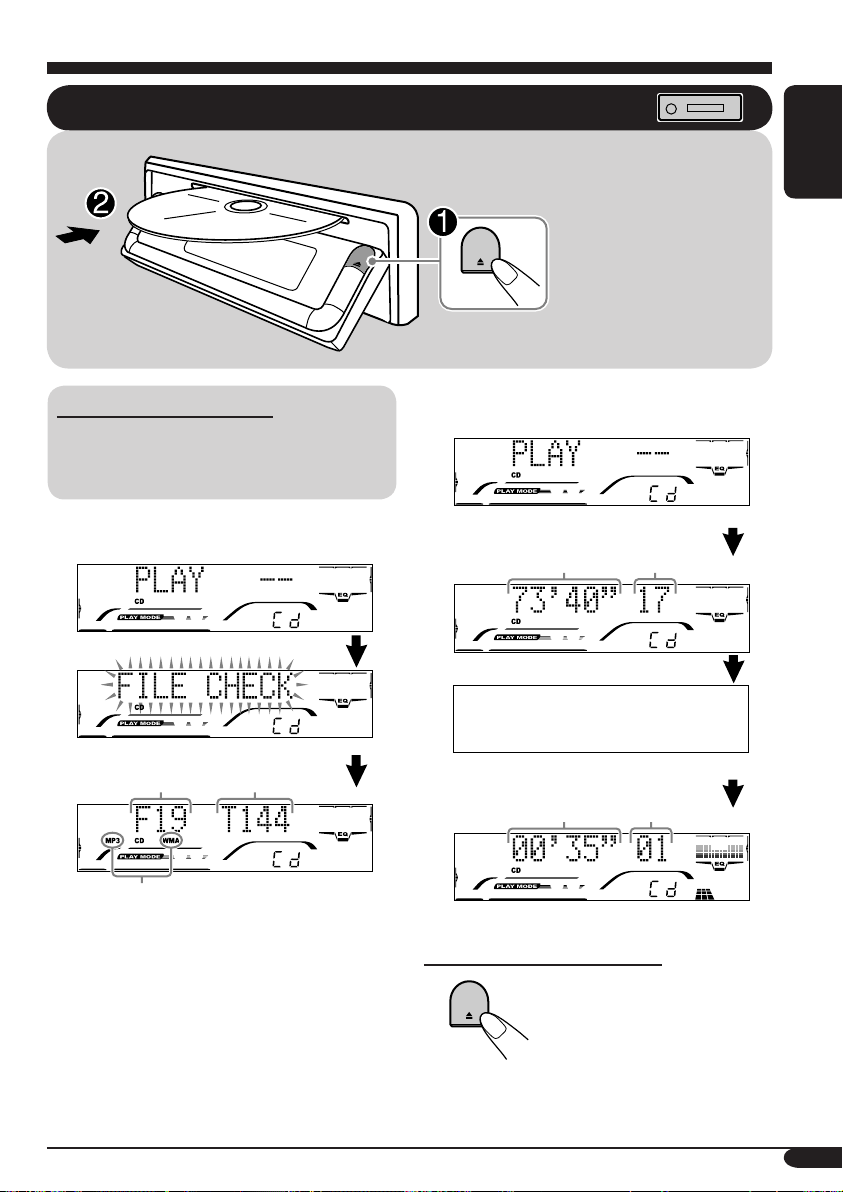
Disc operations
Playing a disc in the receiver
All tracks will be played
repeatedly until you stop
playback.
* The receiver draws the
disc, then the control
panel goes back to
previous position (see
page 24).
ENGLISH
About MP3 and WMA discs
MP3 and WMA (Windows Media® Audio)
“tracks” (words “file” and “track” are used
interchangeably) are recorded in “folders.”
• When inserting an MP3 or a WMA disc:
Total folder
number
*
When playback starts, disc information will
automatically appear (see page 15).
*
Either the MP3 or WMA indicator lights up
depending on the detected file.
Total file
number
• When inserting an audio CD or a CD Text
disc:
Total playing time
of the inserted disc
CD Text: Disc title/performer =
Track title appear automatically.
Elapsed playing
time
Total track number
of the inserted disc
Current track
number
To stop play and eject the disc
11
Page 12
ENGLISH
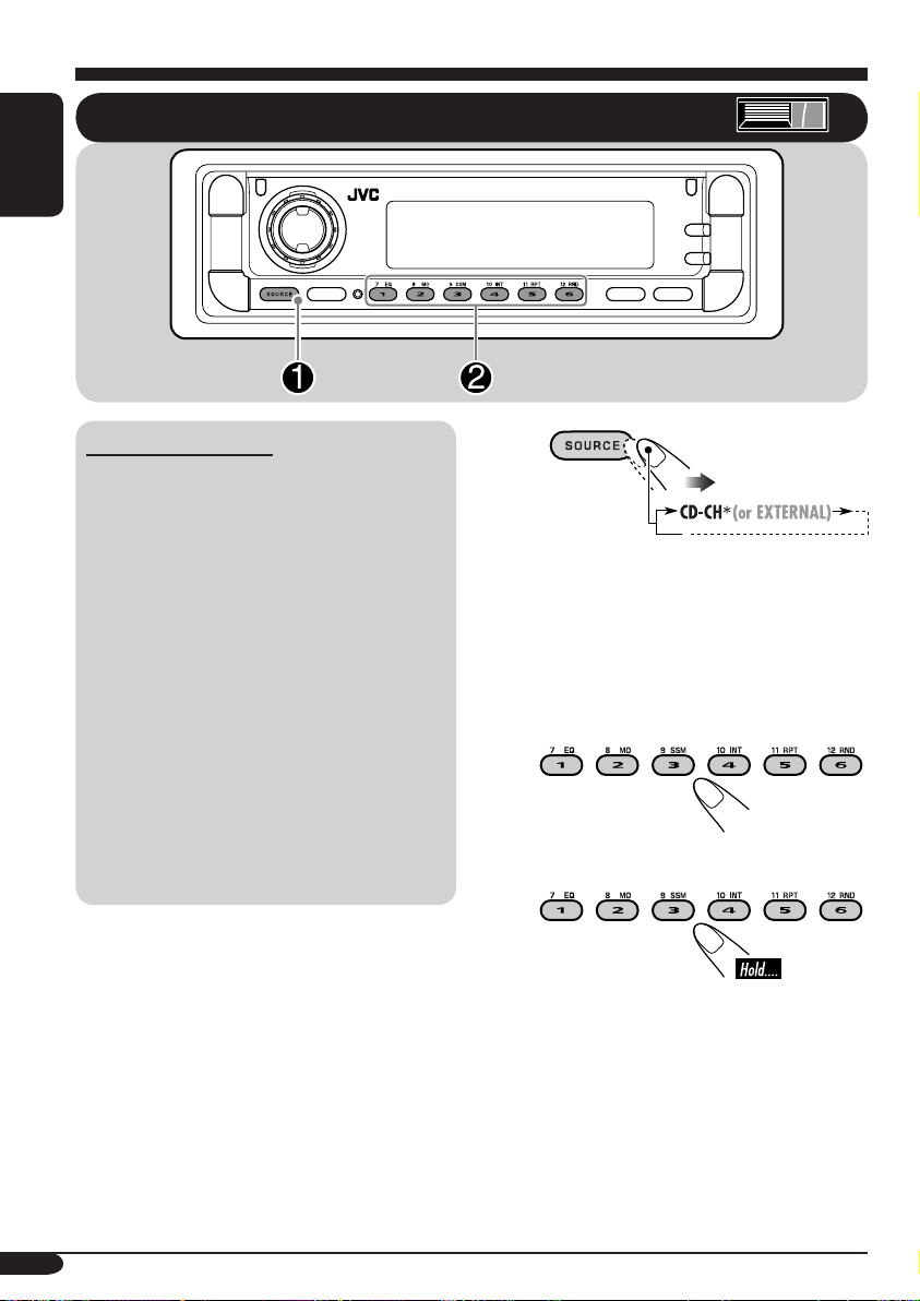
Playing discs in the CD changer
About the CD changer
It is recommended to use the JVC MP3compatible CD changer with your receiver.
• You can also connect other CH-X series
CD changers (except CH-X99 and
CH-X100). However, they are not
compatible with MP3 discs, so you cannot
play back MP3 discs.
• You cannot use the KD-MK series CD
changers with this receiver.
• Disc text information recorded in the CD
Text can be displayed when a JVC CD
Text compatible CD changer is connected.
Before operating your CD changer:
• Refer also to the Instructions supplied
with your CD changer.
• You cannot control and play any WMA
disc in the CD changer.
~
If you have changed “EXTERNAL
*
IN” setting to “EXTERNAL IN” (see
page 22), you cannot select the CD
changer.
Ÿ Select a disc.
For disc number from 01 – 06:
For disc number from 07 – 12:
12
Page 13

• When the current disc is an MP3 disc:
To fast-forward or reverse the track
Selected disc number
Folder name*
Selected folder number
When playback starts, disc information will
automatically appear (see page 15).
* “ROOT” appears if no folder is included in
the disc.
• When the current disc is an audio CD or a
CD Text disc:
Fast-forwards.
Reverses.
To go to the next or previous tracks
To the following
tracks.
To the beginning of the current track, then
the previous tracks.
To go to the next or previous folders
For MP3 discs:
For WMA discs:
To next folders.
ENGLISH
Selected disc number
CD Text: Disc title/performer =
Track title appear automatically.
Elapsed playing
time
Current track
number
To previous folders.
13
Page 14

To locate a particular track (for CD) or
folder (for MP3 or WMA discs) directly
ENGLISH
To select a number from 01 – 06:
To select a number from 07 – 12:
• To use folder search on MP3/WMA discs, it
is required that folders are assigned with 2
digit numbers at the beginning of their folder
names—01, 02, 03, and so on.
• To select a particular track in a folder
(for MP3 or WMA disc) after selecting a
folder:
2
First time you press +10 or –10 button, the
track skips to the nearest higher or lower
track with a track number of multiple ten
(ex. 10th, 20th, 30th).
Then each time you press the button, you
can skip 10 tracks.
• After the last track, the first track will be
selected and vice versa.
3
Prohibiting disc ejection
You can lock a disc in the loading slot.
Other main functions
Skipping a track quickly during play
• For MP3 or WMA disc, you can skip a track
within the same folder.
Ex.: To select track 32 while playing track 6
1
14
To cancel the prohibition, repeat the same
procedure.
Page 15

Changing the display information
While playing an audio CD or a CD Text ( / )
*1 If the current disc is an audio CD, “NO NAME” appears. To assign a title to an audio CD,
see page 23.
While playing an MP3 ( / ) or WMA ( ) disc
• When “TAG DISPLAY” is set to “TAG DISP ON” (see page 22)
ENGLISH
2
If an MP3/WMA file does not have ID3 tags, folder name and file name appear. In this
*
case, the TAG indicator will not light up.
• When “TAG DISPLAY” is set to “TAG DISP OFF”
15
Page 16

Selecting the playback modes
You can use only one of the following playback modes at a time.
ENGLISH
1
2 Select your desired playback mode.
Repeat play
Mode Plays repeatedly
TRK RPT: The current track.
• RPT lights up.
FLDR RPT*
•
DISC RPT*
•
1
: All tracks of the current folder.
and RPT light up.
2
: All tracks of the current disc.
and RPT light up.
RPT OFF: Cancels repeat play.
Ex.: When “TRK RPT” is selected while
playing an MP3 disc in the receiver
Random play
Mode Plays at random
FLDR RND*1: All tracks of the current folder, then
tracks of the next folder and so on.
•
and RND light up.
DISC RND: All tracks of the current disc.
•
MAG RND*
and RND light up.
2
: All tracks of the inserted discs.
• RND lights up.
Ex.: When “DISC RND” is selected while
playing an MP3 disc in the receiver
Intro scan
RND OFF: Cancels random play.
Mode Plays at the beginnings
TRK INT: All tracks of the current disc.
• INT lights up.
FLDR INT*
1
: The first track of every folder of the
current disc.
•
DISC INT*
•
Ex.: When “TRK INT” is selected while
playing an MP3 disc in the receiver
1
*
Only while playing an MP3 ( / ) or WMA ( ) disc.
2
Only while playing discs in the CD changer ( ).
*
INT OFF: Cancels intro scan.
and INT light up.
2
: The first tracks of the inserted discs.
and INT light up.
16
Page 17

Sound adjustments
Selecting preset sound modes (iEQ: intelligent equalizer)
ENGLISH
You can select a preset sound mode suitable to
the music genre.
~
Ÿ
!
FLAT (no sound mode is applied) “
HARD ROCK “ R&B “ POP “
JAZZ “ DANCE MUSIC “
COUNTRY “ REGGAE “
CLASSIC “ USER 1 “ USER 2 “
USER 3 “ (back to the beginning)
Indication pattern changes
for each sound mode.
To select the sound mode directly
Ex.: When “HARD ROCK” is selected
17
Page 18

Adjusting the sound
You can adjust the sound characteristics to your
preference.
ENGLISH
1
* Only for KD-AR760.
2
Indication pattern changes as you
adjust the fader or balance.
Ex.: When “FAD” is selected
Indication To do: Range
FAD*1
(fader)
BAL
(balance)
LOUD
(loudness)
WOOFER*
3
VOL*
(volume)
*1 If you are using a two-speaker system, set
the fader level to “00.”
2
*
Only for KD-AR760: This takes effect only
when a subwoofer is connected.
3
*
Normally the control dial works as the
volume control. So you do not have to select
“VOL” to adjust the volume level.
4
*
Depending on the amplifier gain control
setting. (See page 22 for details.)
Adjust the front
and rear speaker
balance.
Adjust the left
and right speaker
balance.
Boost low and
high frequencies
to produce a wellbalanced sound at
low volume level.
2
Adjust the
subwoofer output
level.
Adjust the
volume.
R06 (Rear
only)
to
F06 (Front
only)
L06 (Left
only)
to
R06 (Right
only)
LOUD ON
LOUD
OFF
00 (min.)
to
08 (max.)
00 (min.)
to
30 or 50
(max.)*
4
18
Page 19

Storing your own sound
adjustments
* By pressing 4
directly move as follows:
or ¢, you can
You can adjust the sound modes and store your
own adjustments in memory.
1
2
3
Ex.: When “JAZZ” is selected
4 Select the sound elements to adjust.
5 Adjust the selected sound elements.
Indication
LEVEL –06
(min.) to
+06
(max.)
FREQ. 60Hz
80Hz
100Hz
120Hz
WIDTH 1 (min.)
to
4 (max.)
Preset values
LOW MID HI
–06
(min.) to
+06
(max.)
1 (min.)
to
2 (max.)
–06
(min.) to
+06
(max.)
8kHz
10kHz
12kHz
15kHz
6 Repeat steps 4 and 5 to set (or
adjust) the other sound elements.
ENGLISH
LOW LEVEL* = LOW FREQ =
LOW WIDTH = MID LEVEL* =
MID WIDTH = HI (high) LEVEL* =
HI (high) FREQ = (back to the
beginning)
• LEVEL (LOW, MID, HI):
Adjust the enhancement level.
• FREQ (LOW, HI):
Select the center frequency to adjust.
• WIDTH (LOW, MID):
Select the band width level.
7 Select one of the user sound modes
(USER 1, USER 2, USER 3).
8 Store the adjustments.
19
Page 20

General settings — PSM
Basic procedure
3 Adjust the PSM item selected.
You can change PSM (Preferred Setting Mode)
items listed (except for SID) in the table that
ENGLISH
follows.
1
2 Select a PSM item.
Ex.: When you select “DIMMER MODE”
Indications Selectable settings, [reference page]
DEMO MODE
Display demonstration
DEMO ON: [Initial]; Display demonstration will be activated
DEMO OFF: Cancels.
4 Repeat steps 2 and 3 to adjust the
other PSM items if necessary.
5 Finish the procedure.
automatically if no operation is done for about
20 seconds, [8].
CLOCK HOUR
Hour adjustment
CLOCK MINUTE
Minute adjustment
CLOCK DISP
Clock display
20
1 – 12, [8]
[Initial: 1 (1:00)]
00 – 59, [8]
[Initial: 00 (1:00)]
CLK DISP ON: [Initial]; Clock display is shown on the lower part
of the display.
CLK DISP OFF: Current source indication (ex. station band, disc
number, etc.) is shown on the lower part of the
display.
• Pressing DISP repeatedly will show the other information for about
5 seconds.
Page 21

Indications Selectable settings, [reference page]
CLOCK ADJUST*
1
Clock adjustment
T-ZONE*
1, *2
Time zone
1, *2
DST*
Daylight savings time
1
SID*
SIRIUS® ID
LEVELMETER
Level/audio meter
DIMMER MODE
Dimmer
AUTO: [Initial]; The built-in clock will be adjusted automatically
using the clock data provided via the SIRIUS® radio
channel.
OFF: Cancels.
Select your residential area from one of the following time zone for
clock adjustment.
EASTERN [Initial] “ ATLAN TIC “ NEWFOUND “
ALASKA “ PACIF IC “ MOUNTAIN “ CENTRAL “
(back to the beginning)
Activates this if your residential area is subject to DST.
ON: [Initial]; Activates daylight savings time.
OFF: Cancels.
The 12-digits SIRIUS identification number scrolls on the display
after 5 seconds, [26].
• Press SEL to resume the previous display.
LEVEL 1[Initial]/LEVEL 2: Display the audio level meter with
different illumination pattern.
EQ & LEVEL: Display the equalizer pattern and the audio level
meter.
SILENT: Display the equalizer pattern and volume level
meter.
DIMMER AUTO: [Initial]; Dims the display when you turn on the
headlights.
DIMMER ON: Activates dimmer.
DIMMER OFF: Cancels.
ENGLISH
TELEPHONE*
3
Telephone muting
CONTRAST
Display contrast
MUTING 1/MUTING 2: Select either one which mutes the sounds
while using the cellular phone.
• If CD or CD changer is selected as the source, playback pauses
during telephone muting.
MUTING OFF: [Initial]; Cancels.
01 – 10: Adjust the display contrast to make the display indications
clear and legible.
[Initial: 08]
To be continued...
21
Page 22

Indications Selectable settings, [reference page]
SCROLL MODE*
Scroll
ENGLISH
WOOFER FREQ*
Subwoofer cutoff
frequency
LINE ADJ*
3
Line input level
EXTERNAL IN*
External input
TAG DISPLAY
Tag display
AMP.GAIN
Amplifier gain control
4
SCROLL ONCE: [Initial]; Scrolls the disc information once.
SCROLL AUTO:
Repeats scrolling (5-second interval in between).
SCROLL OFF: Cancels.
• Pressing DISP for more than one second can scrolls the display
regardless of the setting.
3
FREQ 55 Hz: Frequencies lower than 55 Hz are send to the
subwoofer.
FREQ 85 Hz: [Initial]; Frequencies lower than 85 Hz are send to
the subwoofer.
FREQ 115 Hz: Frequencies lower than 115 Hz are send to the
subwoofer.
VOL 0 0 – VOL 05: Adjust the line input level properly when an
external component is connected to the LINE
IN plugs.
[Initial: VOL 00]
5
CHANGER: [Initial]; To use a JVC CD changer, [12].
EXTERNAL IN: To use another external component (other than
SIRIUS DLP), [25].
TAG DISP ON: [Initial]; Shows the ID3 tag while playing
MP3/WMA tracks, [15].
TAG D I S P OFF : Cancels.
You can change the maximum volume level of this receiver.
LOW POWER : VOL 00 – VOL 30 (Select this if the maximum
power of the speaker is less than 50 W to prevent
them from damaging the speaker.)
HIGH POWER: [Initial]; VOL 00 – VOL 50
3
OFF*
: Deactivates the built-in amplifier.
AREA
Tuner channel interval
1
Displayed only when SIRIUS radio is connected.
*
2
*
Displayed only when “CLOCK ADJUST” is set to “AUTO.”
3
*
Only for KD-AR760.
4
*
Some characters or symbols will not be shown (and will be blanked) or substituted on the
display.
5
*
Displayed only when one of the following sources is selected —FM, AM, CD, or LINE IN (only
for KD-AR760).
22
AREA EU:
Select this when using the receiver in an area other than
North and South America. (FM: 50 kHz—manual tuning,
100 kHz—auto search; AM: 9 kHz)
AREA US: [Initial]; Select this when using the receiver in North or
South America. (FM: 200 kHz; AM: 10 kHz)
Page 23

Other main functions
Assigning titles to the sources
You can assign names to station frequencies,
CDs (both in this receiver and in the CD
changer), and external component (Line Input—
only for KD-AR760).
Sources
Station
frequencies
CDs/CD-CH*
External
component
(Line Input)*
1
You cannot assign a name to a CD Text or
*
an MP3/WMA disc.
2
*
Only for KD-AR760.
1
2
1 Select the sources.
• For station frequencies: Select tuner.
• For a CD in this receiver: Insert a CD.
• For CDs in the CD changer: Select
“CD-CH,” then select a disc number.
Maximum number of
characters
Up to 9 characters (up
to 30 station frequencies
including both FM and AM)
Up to 32 characters (up to
30 discs)
Up to 12 characters
3 Assign a title.
1 Select a character set.
ENGLISH
2 Select a character.
For available characters,
see page 29.
3 Move to the next (or previous)
character postion.
4 Repeat steps 1 to 3 until you
finish entering the title.
4 Finish the procedure.
2 Enter the disc title assignment mode.
Ex.: When you select CD as the source
To erase the entire title
23
Page 24

Changing the control panel angle
ENGLISH
Detaching the control panel
When detaching or attaching the control panel,
be careful not to damage the connectors on
the back of the control panel and on the panel
holder.
The control panel changes its angle as follows:
Caution:
Do not insert your
finger behind the
control panel.
Detaching the control panel
Before detaching the control panel, be sure to
turn off the power.
Attaching the control panel
24
Page 25

External component operations
Playing an external component
For KD-AR760:
You can connect an external component to the
LINE IN plugs on the rear.
For KD -AR760/KD-G710:
You can connect an external component to the
CD changer jack on the rear using the Line
Input Adapter KS-U57 (not supplied).
Before operating the external component, select
the external input correctly (see page 22).
• For connection, see Installation/Connection
Manual (separate volume).
Ÿ Turn on the connected component
and start playing the source.
! Adjust the volume.
ENGLISH
~
• If “EXTERNAL” does not appear, see
page 22 and select the external input
(“EXTERNAL IN”).
⁄ Adjust the sound as you want.
(See pages 17 – 19.)
25
Page 26

SIRIUS® radio operations
About SIRIUS radio
SIRIUS is a satellite radio that can deliver
digital-quality sound.
SIRIUS has 65 music channels which are all
ENGLISH
commercial-free and 50 channels of sports,
news, and entertainment programs.
You can enjoy and control the SIRIUS
radio digital entertainment channels
from the receiver by connecting the JVC
SIRIUS radio DLP—Down Link Processor
(optionally purchased) to the CD changer
jack on the rear.
• You can also connect the JVC SIRIUS
radio PnP (Plug and Play), KT-SR1000 or
KT-SR2000, using the JVC SIRIUS radio
adapter, KS-U100K (not supplied). By
turning on the power of the receiver, you
can turn on/off the JVC PnP. However,
you cannot control it from this receiver.
GCI (Global Control Information) update:
• If channels are updated after subscription,
updating starts automatically.
“UPDATING” flashes and no sound can
be heard.
• Update takes a few minutes to complete.
• During update, you cannot operate your
SIRIUS radio.
Before operating your SIRIUS radio:
• For connection, see Installation/
Connection Manual (separate volume).
• Refer also to the Instructions supplied
with your SIRIUS radio.
Before you can listen to JVC DLP, activate
your SIRIUS subscription after connection:
1
2
JVC DLP starts updating all the SIRIUS
channels.
“UPDATING” flashes on the display for a
few minutes. No sound can be heard during
update.
Once completed, JVC DLP tunes in to the
preset channel, CH184.
3 Check your SIRIUS ID, see page 21.
4 Contact SIRIUS on the internet at
<http://activate.siriusradio.com/> to activate
your subscription, or you can call SIRIUS
toll-free at 1-888-539-SIRIUS (7474).
“SUB UPDT PRESS ANY KEY” scrolls
on the display once subscription has been
completed.
26
Page 27

Listening to the SIRIUS® radio
ENGLISH
~
Ÿ
! Select a category.
You can tune in to all the channels of
every category by selecting “ALL.”
Selecting a particular category
(SPORTS, ENTERTAINMENT, etc.)
allows you to enjoy only the channels
from the selected category.
⁄ Select a channel for listening.
Press and hold these buttons change the
channels rapidly.
• When changing the category or channel,
invalid and unsubscribed channels are skipped
automatically.
27
Page 28

Storing channels in memory
You can preset six channels for each band.
ENGLISH
Ex.: Storing a channel into preset number 4.
1 Perform steps ~ to ⁄ on page 27, to
tune in to a channel you want.
2
Preset number flashes
for a while.
Listening to a preset channel
1
To change the display information while
listening to a channel
2
3 Select the preset channel (1 – 6) you
want.
28
Page 29

Maintenance
How to clean the connectors
Frequent detachment will deteriorate the
connectors.
To minimize this possibility, periodically wipe
the connectors with a cotton swab or cloth
moistened with alcohol, being careful not to
damage the connectors.
Connector
Moisture condensation
Moisture may condense on the lens inside the
CD player in the following cases:
• After starting the heater in the car.
• If it becomes very humid inside the car.
Should this occur, the CD player may
malfunction. In this case, eject the disc and
leave the receiver turned on for a few hours
until the moisture evaporates.
To keep discs clean
A dirty disc may not play correctly.
If a disc does become dirty, wipe
it with a soft cloth in a straight line
from center to edge.
• Do not use any solvent (for
example, conventional record cleaner, spray,
thinner, benzine, etc.) to clean discs.
To play new discs
New discs may have some rough
spots around the inner and outer
edges. If such a disc is used, this
receiver may reject the disc.
To remove these rough spots, rub the edges
with a pencil or ball-point pen, etc.
Available character
Capital letters
Small letters
ENGLISH
How to handle discs
When removing a disc from
its case, press down the center
holder of the case and lift the
disc out, holding it by the
edges.
• Always hold the disc by the edges. Do not
touch its recording surface.
When storing a disc into its case, gently insert
the disc around the center holder (with the
printed surface facing up).
• Make sure to store discs into the cases after
use.
Do not use the following discs:
Wrap disc
Center holder
Sticker
Number and symbols
Sticker
residue
Disc
Stick-on
label
29
Page 30

More about this receiver
Basic operations
Turning off the power
• If you turn off the power while listening to a
disc, disc play will start from where playback
ENGLISH
has been stopped previously, next time you
turn on the power.
Selecting the sources
• When no disc is loaded in the receiver, “CD”
cannot be selected.
• Without connecting to the SIRIUS radio or
CD changer, “SIRIUS” or “CD-CH” cannot
be selected.
Tuner operations
Storing stations in memory
• During SSM search...
– All previously stored stations are erased and
stations are stored newly.
– Received stations are preset in No. 1 (lowest
frequency) to No. 6 (highest frequency).
– When SSM is over, the station stored in
No. 1 will be automatically tuned in.
• When storing a station manually, a previously
preset station is erased when a new station is
stored in the same preset number.
Disc operations
General
• This receiver has been designed to reproduce
CDs/CD Texts, and CD-Rs (Recordable)/
CD-RWs (Rewritable) in audio CD (CD-DA),
MP3 and WMA format.
• When a disc has been loaded, selecting “CD”
for the playback source starts disc play.
Playing a disc
• While fast-forwarding or reversing on an MP3
or WMA disc, you can only hear intermittent
sounds.
Playing a CD-R or CD-RW
• Use only “finalized” CD-Rs or CD-RWs.
• This receiver can play back only the files of
the same type which is first detected if a disc
includes both audio CD (CD-DA) files and
MP3/WMA files.
• This receiver can play back multi-session
discs; however, unclosed sessions will be
skipped while playing.
• Some CD-Rs or CD-RWs may not play
back on this receiver because of their disc
characteristics, and for the following causes:
– Discs are dirty or scratched.
– Moisture condensation occurs on the lens
inside the receiver.
– The pickup lens inside the receiver is dirty.
– CD-R/CD-RW on which the files are
written with “Packet Write” method.
– There are improper recording conditions
(missing data, etc.) or media conditions
(stain, scratch, warp, etc.).
• CD-RWs may require a longer readout time
since the reflectance of CD-RWs is lower
than that of regular CDs.
• Do not use the following CD-Rs or CD-RWs:
– Discs with stickers, labels, or protective seal
stuck to the surface.
– Discs on which labels can be directly
printed by an ink jet printer.
Using these discs under high temperatures
or high humidity may cause malfunctions or
damage to discs.
Inserting a disc
• When a disc is inserted upside down, the
control panel moves down, and the disc
automatically ejects from the loading slot.
• Do not insert 8 cm discs (single CD) and
unusual shape discs (heart, flower, etc.) into
the loading slot.
30
Playing an MP3/WMA disc
• This receiver can play back MP3/WMA files
with the extension code <.mp3> or <.wma>
(regardless of the letter case—upper/lower).
• This receiver can show the names of albums,
artists (performer), and ID3 Tag (Version 1.0,
1.1, 2.2, 2.3, or 2.4) for MP3 files and for
WMA files.
Page 31

• This receiver can display only one-byte
characters. No other characters can be
correctly displayed.
• This receiver can play back MP3/WMA files
meeting the conditions below:
– Bit rate: 8 kbps — 320 kbps
– Sampling frequency:
48 kHz, 44.1 kHz, 32 kHz (for MPEG-1)
24 kHz, 22.05 kHz, 16 kHz (for MPEG-2)
– Disc format: ISO 9660 Level 1/ Level 2,
Romeo, Joliet, Windows long file name
• The maximum number of characters for file/
folder names vary among the disc format used
(includes 4 extension characters—<.mp3> or
<.wma>).
– ISO 9660 Level 1: up to 12 characters
– ISO 9660 Level 2: up to 31 characters
– Romeo*: up to 128 (72) characters
– Joliet*: up to 64 (36) characters
– Windows long file name*: up to 128 (72)
characters
* The parenthetic figure is the maximum
number of characters for file/folder names
in case the total number of files and folders
is 313 or more.
• This receiver can recognize the total of 512
files, of 200 folders, and of 8 hierarchies.
• This receiver can play back the files recorded
in VBR (variable bit rate).
The files recorded in VBR have a discrepancy
in elapsed time display, and do not show
the actual elapsed time. Especially, after
performing the search function, this difference
becomes noticeable.
• This receiver cannot play back the following
files:
– MP3 files encoded with MP3i and MP3
PRO formats.
– MP3 files encoded in an unappropriated
format.
– MP3 files encoded with Layer 1/2.
– WMA files encoded with lossless,
professional, and voice formats.
– WMA files which are not based upon
Windows Media
®
Audio.
– WMA formatted files copy-protected with
DRM.
– Files which have the data such as WAVE,
ATRAC3, etc.
• The search function works but search speed is
not constant.
Changing the source
• If you change the source, playback also stops
(without ejecting the disc).
Next time you select “CD” for the playback
source, disc play starts from where it has been
stopped previously.
Ejecting a disc
• If the ejected disc is not removed within
15 seconds, the disc is automatically inserted
again into the loading slot to prevent it from
dust. (Disc will not play this time.)
General settings—PSM
• If you have change the setting from
“TAG DISP OFF” to “TAG DISP ON” while
playing MP3/WMA file, the tag display will
be activated when the next file starts playing.
• If you change the “AMP.GAIN” setting from
“HIGH POWER” to “LOW POWER” while
the volume level is set higher than “VOL 30,”
the receiver automatically changes the volume
level to “VOL 30.”
Other main functions
• If you try to assign a title to a 31st disc or to
the 31st station frequency, “NAME FULL”
appears. Delete unwanted titles before
assignment.
• Titles assigned to discs in the CD changer can
also be shown if you playback the disc from
the receiver.
• The control panel moves to its previous angle
each time you turn on the power.
ENGLISH
31
Page 32

Troubleshooting
What appears to be trouble is not always serious. Check the following points before calling a service
center.
ENGLISH
• Sound cannot be heard
General
• The receiver does not
• SSM automatic presetting
• Static noise while listening
FM/AM
• Disc cannot be played
• CD-R/CD-RW cannot be
• Tracks on the CD-R/
• Disc can be neither played
Symptoms Causes Remedies
from the speakers.
work at all.
does not work.
to the radio.
back.
played back.
CD-RW cannot be
skipped.
back nor ejected.
The volume level is set to
the minimum level.
Connections are incorrect. Check the cords and
The built-in microcomputer
may have functioned
incorrectly due to noise, etc.
Signals are too weak. Store stations manually.
The antenna is not connected
firmly.
Disc is inserted upside
down.
CD-R/CD-RW is not
finalized.
Disc is locked. Unlock the disc (see page
Adjust it to the optimum
level.
connections.
Reset the receiver (see page
2).
Connect the antenna firmly.
Insert the disc correctly.
• Insert a finalized CD-R/
CD-RW.
•
Finalize the CD-R/CD-RW
with the component which
you used for recording.
14).
32
• Disc sound is sometimes
Disc playback
interrupted.
• “NO DISC” appears on
the display.
• When “PUSH RESET”
appears on the display.
The CD player may have
functioned incorrectly.
You are driving on rough
roads.
Disc is scratched. Change the disc.
Connections are incorrect. Check the cords and
Disc is inserted incorrectly. Insert the disc correctly.
There is something blocking
the control panel movement.
Eject the disc forcibly (see
page 2).
Stop playback while driving
on rough roads.
connections.
Reset the receiver (see page
2).
Page 33

Symptoms Causes Remedies
• Disc cannot be played
back.
• Noise is generated. The track played back is not
• A longer readout time is
required (“FILE CHECK”
keeps flashing on the
display).
MP3/WMA playback
• Tracks cannot be played
back as you have intended
them to play.
No MP3/WMA tracks are
recorded on the disc.
MP3/WMA tracks do not
have the extension code
<.mp3> or <.wma> in their
file names.
MP3/WMA tracks are not
recorded in the format
compliant with ISO 9660
Level 1, Level 2, Romeo, or
Joliet.
an MP3/WMA file (although
it has the extension code
<.mp3> or <.wma>).
Readout time varies due to
the complexity of the folder/
file configuration.
Playback order is determined
when the files are recorded.
Change the disc.
ENGLISH
Add the extension code
<.mp3> or <.wma> to their
file names.
Change the disc.
(Record MP3/WMA
tracks using a compliant
application.)
Skip to another track or
change the disc. (Do not add
the extension code <.mp3>
or <.wma> to non-MP3 or
WMA tracks.)
Do not use too many
hierarchies and folders.
• Elapsed playing time is
not correct.
• “NO FILES” appears on
the display.
• Correct characters are
not displayed (e.g. album
name).
This sometimes occurs
during play. This is caused
by how the tracks are
recorded on the disc.
The current disc does not
contain any MP3/WMA
tracks.
This receiver can only
display alphabets (capital:
A – Z, small: a – z),
numbers, and a limited
number of symbols.
Insert a disc that contains
MP3/WMA tracks.
33
Page 34

Symptoms Causes Remedies
• “NO DISC” appears on the
ENGLISH
• “NO MAG” appears on
• “RESET 8” appears on the
CD changer
• “RESET 1” – “RESET 7”
• The CD changer does not
• “CALL 1-888-539-
• “NO SIGNAL” scrolls on
• “NO ANTENNA” scrolls
• “NO CHANNEL” appears
SIRIUS
• “NO (information)*”
display.
the display.
display.
appears on the display.
work at all.
SIRIUS TO SUBSCRIBE”
scrolls on the display.
the display.
on the display.
on the display for about
5 seconds, then returns to
the previous display.
appears or scrolls on the
display.
No disc is in the magazine.
Disc is inserted upside down.
No magazine is loaded in the
CD changer.
This receiver is not
connected to the CD changer
correctly.
The built-in microcomputer
may function incorrectly due
to noise, etc.
Subscription has not been
done.
Signals are too weak. Move to an area with
The antenna is not connected
firmly.
No broadcast on the selected
channel.
No text information for the
selected channel.
Insert disc into the magazine.
Insert disc correctly.
Insert the magazine.
Connect this receiver and the
CD changer correctly and
press the reset button of the
CD changer.
Press the reset button of the
CD changer.
Reset the receiver (see page
2).
Starts subscribing (see page
26).
stronger signals.
Connect the antenna firmly.
Select another channel or
continue listening to the
previous channel.
• No sound can be heard. “UPDATING” flashes on
• SIRIUS radio does not
work at all.
* NO CATEGORY, NO CHANNEL, NO ARTIST, NO COMPOSER, and NO SONG/PROGRAM
• Microsoft and Windows Media are either registered trademarks or trademarks of Microsoft
Corporation in the United States and/or other countries.
34
the display.
The built-in microcomputer
may function incorrectly due
to noise, etc.
The receiver is updating the
channel information and
it takes a few minutes to
complete.
Reconnect the SIRIUS radio
after a few seconds.
Page 35

Specifications
AUDIO AMPLIFIER SECTION
Power Output:
20 W RMS × 4 Channels at 4 Ω
and ≤ 1% THD+N
Signal to Noise Ratio:
80 dBA (reference: 1 W into 4 Ω)
Load Impedance: 4 Ω (4 Ω to 8 Ω allowance)
Equalizer Control Range:
Low: ±12 dB (60 Hz, 80 Hz, 100 Hz, 120 Hz)
Mid: ±12 dB
High: ±12 dB (8 kHz, 10 kHz, 12 kHz, 15 kHz)
Frequency Response: 40 Hz to 20 000 Hz
Line-In Level/Impedance:
KD-AR760: 1.5 V/20 kΩ load
Line-Out Level/Impedance:
KD-AR760: 5.0 V/20 kΩ load (full scale)
KD-G710: 4.0 V/20 kΩ load (full scale)
Output Impedance: 1 kΩ
Subwoofer-Out Level/Impedance:
KD-AR760: 2.0 V/20 kΩ load (full scale)
Other terminals:
CD changer, LINE IN (for KD-AR760),
SUBWOOFER (for KD-AR760)
TUNER SECTION
Frequency Range:
FM: 87.5 MHz to 107.9 MHz
(with channel interval set to 200 kHz)
87.5 MHz to 108.0 MHz
(with channel interval set to 50 kHz)
AM: 530 kHz to 1 710 kHz
(with channel interval set to 10 kHz)
531 kHz to 1 602 kHz
(with channel interval set to 9 kHz)
[FM Tuner]
Usable Sensitivity: 11.3 dBf (1.0 µV/75 Ω)
50 dB Quieting Sensitivity: 16.3 dBf (1.8 µV/75 Ω)
Alternate Channel Selectivity (400 kHz): 65 dB
Frequency Response: 40 Hz to 15 000 Hz
Stereo Separation: 35 dB
Capture Ratio: 1.5 dB
[AM Tuner]
Sensitivity: 20 µV
Selectivity: 35 dB
CD PLAYER SECTION
Type: Compact disc player
Signal Detection System: Non-contact optical
pickup (semiconductor laser)
Number of channels: 2 channels (stereo)
Frequency Response: 5 Hz to 20 000 Hz
Dynamic Range: 96 dB
Signal-to-Noise Ratio: 98 dB
Wow and Flutter: Less than measurable limit
MP3 decoding format:
MPEG1/2 Audio Layer 3
Max. Bit Rate: 320 Kbps
WMA (Windows Media
format:
Max. Bit Rate: 192 Kbps
®
Audio) decoding
GENERAL
Power Requirement:
Operating Voltage:
DC 14.4 V (11 V to 16 V allowance)
Grounding System: Negative ground
Allowable Operating Temperature:
0°C to +40°C (32°F to 104°F)
Dimensions (W × H × D):
Installation Size (approx.):
182 mm × 52 mm × 159 mm
(7-3/16” × 2-1/16” × 6-5/16”)
Panel Size (approx.):
188 mm × 58 mm × 12 mm
(7-7/16” × 2-5/16” × 1/2”)
Mass (approx.):
1.5 kg (3.4 lbs) (excluding accessories)
Design and specifications are subject to change
without notice.
If a kit is necessary for your car, consult
your telephone directory for the nearest car
audio speciality shop.
ENGLISH
35
Page 36

Having TROUBLE with operation?
Please reset your unit
Refer to page of How to reset your unit
Still having trouble??
USA ONLY
Call 1-800-252-5722
http://www.jvc.com
We can help you!
EN, SP, FR
© 2004 Victor Company of Japan, Limited
1004DTSMDTJEIN
Page 37

GET0247-002A
Removing the receiver / Extracción de la unidad / Retrait de l’appareil
Before removing the receiver, release the rear section.
Antes de extraer la unidad, libere la sección trasera.
Avant de retirer l’appareil, libérer la section arrière.
[J]
KD-AR760/KD-G710
Installation/Connection Manual
Manual de instalación/conexión
Manuel d’installation/raccordement
1004DTSMDTJEIN
EN, SP, FR
ENGLISH
This receiver is designed to operate on 12 V DC, NEGATIVE
ground electrical systems. If your vehicle does not have this
system, a voltage inverter is required, which can be purchased
at JVC car audio dealers.
Parts list for installation and connection
The following parts are provided for this receiver.
After checking them, please set them correctly.
A / B
Hard case/Control panel
Estuche duro/Panel de
control
Etui de transport/
Panneau de commande
F
Remote controller
Control remoto
Télécommade
G
Washer (ø5)
Arandela (ø5)
Rondelle (ø5)
C
Sleeve
Cubierta
Manchon
H
Lock nut (M5)
Tuerca de seguridad
(M5)
Ecrou d’arrêt (M5)
ESPAÑOL
Esta unidad está diseñada para funcionar con 12 V de CC,
con sistemas eléctricos de masa NEGATIVA. Si su vehículo
no posee este sistema, será necesario un inversor de tensión,
que puede ser adquirido en los concesionarios de JVC de
equipos de audio para automóviles.
Lista de piezas para instalación y conexión
Con esta unidad se suministran las siguientes piezas.
Después de inspeccionarlas, colóquelas correctamente.
D
Trim plate
Placa de guarnición
Plaque d’assemblage
I
Mounting bolt—M5 x 20 mm
(M5 x 13/16”)
Perno de montaje—M5 x 20 mm
(M5 x 13/16 pulgada)
Boulon de montage—M5 x 20 mm
(M5 x 13/16 pouces)
FRANÇAIS
Cet appareil est conçu pour fonctionner sur des sources de
courant continu de 12 V à masse NEGATIVE. Si votre véhicule
n’offre pas ce type d’alimentation, il vous faut un convertisseur
de tension, que vous pouvez acheter chez un revendeur
d’autoradios JVC.
Liste des pièces pour l’installation et
raccordement
Les pièces suivantes sont fournies avec cet appareil.
Après vérification, veuillez les placer correctement.
E
Power cord
Cordón de alimentación
Cordon d’alimentation
J
Rubber cushion
Cojín de goma
Amortisseur en
caoutchouc
K
Handles
Manijas
Poignées
L
Battery
Pila
Pile
INSTALLATION
(IN-DASH MOUNTING)
The following illustration shows a typical installation. If you
have any questions or require information regarding installation
kits, consult your JVC car audio dealer or a company supplying
kits.
• If you are not sure how to install this receiver correctly, have it
installed by a qualified technician.
1
*
When you stand the receiver, be careful not to
damage the fuse on the rear.
1
*
Al poner la unidad vertical, tenga cuidado
de no dañar el fusible provisto en la parte
posterior.
1
*
Lorsque vous mettez l’appareil à la verticale,
faire attention de ne pas endommager le fusible
situé sur l’arrière.
INSTALACION (MONTAJE EN EL
TABLERO DE INSTRUMENTOS)
La siguiente ilustración muestra una instalación típica. Si
tiene alguna pregunta o necesita información acerca de las
herramientas para instalación, consulte con su concesionario
de JVC de equipos de audio para automóviles o a una
compañía que suministra tales herramientas.
• Si usted no está seguro de cómo instalar correctamente la
unidad, hágala instalar por un técnico cualificado.
Fit the projections outside
the receiver.
Haga encajar los salientes
del exterior de la unidad.
Fixez les projections à
l’extérieur de l’appareil.
INSTALLATION (MONTAGE
DANS LE TABLEAU DE BORD)
L’illustration suivante est un exemple d’installation typique. Si
vous avez des questions ou avez besoin d’information sur des
kits d’installation, consulter votre revendeur d’autoradios JVC
ou une compagnie d’approvisionnement.
• Si l’on n’est pas sûr de pouvoir installer correctement cet
appareil, le faire installer par un technicien qualifié.
Do the required electrical connections.
Realice las conexiones eléctricas requeridas.
Réalisez les connexions électriques.
Bend the appropriate tabs to hold
the sleeve firmly in place.
Doble las lengüetas apropiadas
para retener firmemente la manga
en su lugar.
Tordez les languettes appropriées
pour maintenir le manchon en place.
Insert the two handles, then pull
them as illustrated so that the
receiver can be removed.
Inserte las dos manijas y, a
continuación, extráigalas de la
manera indicada en la ilustración
para poder desmontar la unidad.
Insérez les deux poignées, puis
tirez de la façon illustrée de façon
à retirer l’appareil.
Caution when installing / Precaución en la instalación /
Précautions lors de l’installation:
Fit the receiver into the mounting sleeve by using four corners of the trim plate.
• DO NOT press the panel (shaded in the illustration).
Introduzca el receptor en la manga de montaje utilizando las cuatro esquinas
de la placa decorativa.
• NO presione el panel (sombreado en la ilustración).
Fixez l’autoradio sur le manchon de montage en utilisant les quatre coins de la
plaque de garniture.
• NE POUSSEZ PAS sur le panneau (en gris sur l’illustration).
1
Page 38

When using the optional stay / Cuando emplea un
soporte opcional / Lors de l’utilisation du hauban en
option
Fire wall
Tabique a prueba de incendios
Cloison
Dashboard
Tablero de
instrumentos
Tableau de bord
Stay (option)
Soporte (opción)
Hauban (en option)
Screw (option)
Tornillo (opción)
Vis (en option)
When installing the receiver without using the sleeve / Instalación de la unidad sin
utilizar la cubierta / Lors de l’installation de l’appareil scans utiliser de manchon
In a Toyota for example, first remove the car radio and install the receiver in its place.
En un Toyota por ejemplo, primero retire la radio del automóvil y luego instale la unidad en su lugar.
Par exemple dans une Toyota, retirer d’abord l’autoradio et installer l’appareil à la place.
Flat type screws—M5 x 8 mm
(M5 x 3/8”)
Tornillos tipo plano—M5 x 8 mm
(M5 x 3/8 pulgada)*
Vis à tête plate—M5 x 8 mm
(M5 x 3/8 pouces)*
*
Pocket
Compartimiento
Poche
Bracket*
Ménsula*
Support *
Bracket*
Ménsula*
Support *
* Not included for this receiver.
* No suministrado con esta unidad.
* Non fourni avec cet appareil.
Flat type screws—M5 x 8 mm (M5 x 3/8”)*
Tornillos tipo plano—M5 x 8 mm (M5 x 3/8
pulgada)
Vis à tête plate—M5 x 8 mm (M5 x 3/8
pouces)*
*
Install the receiver at an angle of less
than 30˚.
Instale la unidad a un ángulo de menos
de 30˚.
Installez l’appareil avec un angle de
moins de 30˚.
ELECTRICAL CONNECTIONS
To prevent short circuits, we recommend that you disconnect
the battery’s negative terminal and make all electrical
connections before installing the receiver.
• Be sure to ground this receiver to the car’s chassis
again after installation.
Notes:
• Replace the fuse with one of the specified rating. If the fuse
blows frequently, consult your JVC car audio dealer.
• It is recommended to connect to the speakers with maximum
power of more than 50 W (both at the rear and at the front,
with an impedance of 4 Ω to 8 Ω). If the maximum power
is less than 50 W, change “AMP.GAIN” setting to prevent
the speakers from being damaged (see page 22 of the
INSTRUCTIONS).
• To prevent short-circuit, cover the terminals of the UNUSED
leads with insulating tape.
• The heat sink becomes very hot after use. Be careful not to
touch it when removing this receiver.
Note : When installing the receiver on the mounting bracket, make sure to use the 8 mm (3/8”)-long screws.
If longer screws are used, they could damage the receiver.
Nota : Cuando instala la unidad en la ménsula de montaje, asegúrese de utilizar los tornillos de 8 mm
(3/8 pulgada) de longitud. Si se utilizan tornillos más largos, éstos pueden dañar la unidad.
Remarque : Lors de l’installation de l’appareil sur le support de montage, s’assurer d’utiliser des vis d’une
longueur de 8 mm (3/8 pouces). Si des vis plus longues sont utilisées, elles peuvent endommager
l’appareil.
CONEXIONES ELECTRICAS
Para evitar cortocircuitos, recomendamos que desconecte
el terminal negativo de la batería y que efectúe todas las
conexiones eléctricas antes de instalar la unidad.
• Asegúrese de volver a conectar a masa esta unidad al
chasis del automóvil después de la instalación.
Notas:
• Reemplace el fusible por uno con la corriente especificada.
Si el fusible se quemase frecuentemente consulte con
su concesionario de JVC de equipos de audio para
automóviles.
• Se recomienda conectar los altavoces con una potencia
máxima de más de 50 W (tanto atrás como adelante, con
una impedancia de 4 Ω a 8 Ω). Si la potencia máxima es
de menos de 50 W, cambie “AMP.GAIN” para evitar daños
en los altavoces (consulte la página 22 del MANUAL DE
INSTRUCCIONES).
• Para evitar cortocircuitos, cubra los cables NO UTILIZADOS
con cinta aislante.
• El sumidero térmico estará muy caliente después del uso.
Asegúrese de no tocarlo al desmontar esta unidad.
RACCORDEMENTS ELECTRIQUES
Pour éviter tout court-circuit, nous vous recommandons de
débrancher la borne négative de la batterie et d’effectuer tous
les raccordements électriques avant d’installer l’appareil.
• Assurez -vous de raccorder de nouveau la mise à la
masse de cet appareil au châssis de la voiture après
l’installation.
Remarques:
• Remplacer le fusible par un de la valeur précisée. Si le fusible
saute souvent, consulter votre revendeur d’autoradios JVC.
• Il est recommandé de connecter des enceintes avec une
puissance de plus de 50 W (les enceintes arrière et les
enceintes avant, avec une impédance comprise entre
4 Ω et 8 Ω). Si la puissance maximum est inférieure à
50 W, changez “AMP.GAIN” pour éviter d’endommager vos
enceintes (voir page 22 du MANUEL D’INSTRUCTIONS).
• Pour éviter les court-circuits, couvrir les bornes des fils qui ne
sont PAS UTILISÉS avec de la bande isolante.
• Le dissipateur de chaleur devient très chaud après usage.
Faire attention de ne pas le toucher en retirant cet appareil.
Heat sink
Sumidero térmico
Dissipateur de chaleur
PRECAUTIONS on power supply and speaker
connections:
• DO NOT connect the speaker leads of the power cord
to the car battery; otherwise, the receiver will be
seriously damaged.
• BEFORE connecting the speaker leads of the power cord to
the speakers, check the speaker wiring in your car.
TROUBLESHOOTING
PRECAUCIONES sobre las conexiones de la
fuente de alimentación y de los altavoces:
• NO conecte los conductores de altavoz del cable de
alimentación a la batería de automóvil, pues podrían
producirse graves daños en la unidad.
• ANTES de conectar a los altavoces los conductores de
altavoz del cable de alimentación, verifique el conexionado
de altavoz de su automóvil.
LOCALIZACION DE AVERIAS
PRECAUTIONS sur l’alimentation et la
connexion des enceintes:
• NE CONNECTEZ PAS les fils d’enceintes du cordon
d’alimentation à la batterie; sinon, l’appareil serait
sérieusement endommagé.
• AVANT de connecter les fils d’enceintes du cordon
d’alimentation aux enceintes, vérifiez le câblage des
enceintes de votre voiture.
EN CAS DE DIFFICULTES
• The fuse blows.
* Are the red and black leads connected correctly?
• Power cannot be turned on.
* Is the yellow lead connected?
• No sound from the speakers.
* Is the speaker output lead short-circuited?
• Sound is distorted.
* Is the speaker output lead grounded?
* Are the “–” terminals of L and R speakers grounded in
common?
• Noise interfere with sounds.
* Is the rear ground terminal connected to the car’s chassis
using shorter and thicker cords?
• Receiver becomes hot.
* Is the speaker output lead grounded?
* Are the “–” terminals of L and R speakers grounded in
common?
• This receiver does not work at all.
* Have you reset your receiver?
• El fusible se quema.
* ¿Están los conductores rojo y negro correctamente
conectados?
• No es posible conectar la alimentación.
* ¿Está el cable amarillo conectado?
• No sale sonido de los altavoces.
*
¿Está el cable de salida del altavoz cortocircuitado?
• El sonido presenta distorsión.
* ¿Está el cable de salida del altavoz conectado a masa?
* ¿Están los terminales “–” de los altavoces L y R conectados
a una masa común?
• Perturbación de ruido.
* ¿El terminal de tierra trasero está conectado al chasis del
automóvil utilizando los cordones más corto y más grueso?
• La unidad se calienta.
* ¿Está el cable de salida del altavoz conectado a masa?
* ¿Están los terminales “–” de los altavoces L y R conectados
a una masa común?
• Este receptor no funciona en absoluto.
* ¿Reinicializó el receptor?
2
• Le fusible saute.
* Les fils rouge et noir sont-ils racordés correctement?
• L’appareil ne peut pas être mise sous tension.
* Le fil jaune est-elle raccordée?
• Pas de son des enceintes.
* Le fil de sortie d’enceinte est-il court-circuité?
• Le son est déformé.
* Le fil de sortie d’enceinte est-il à la masse?
* Les bornes “–” des enceintes gauche et droit sont-elles mises
ensemble à la masse?
• Interférence avec les sons.
* La prise arrière de mise à la terre est-elle connectée au
châssis de la voiture avec un cordon court et épais?
• L’ a pp a r e i l d e v i e n t c h a u d .
* Le fil de sortie d’enceinte est-il à la masse?
* Les bornes “–” des enceintes gauche et droit sont-elles mises
ensemble à la masse?
• Cet appareil ne fonctionne pas du tout.
* Avez-vous réinitialisé votre appareil?
Page 39

ENGLISH
A
Typical Connections / Conexiones tipicas / Raccordements typiques
Before connecting: Check the wiring in the vehicle
carefully. Incorrect connection may cause serious damage to
this receiver.
The leads of the power cord and those of the connector from
the car body may be different in color.
1 Connect the colored leads of the power cord in the order
specified in the illustration below.
2 Connect the antenna cord.
3 Finally connect the wiring harness to the receiver.
ESPAÑOL FRANÇAIS
Antes de la conexión: Verifique atentamente el conexionado
del vehículo. Una conexión incorrecta podría producir daños
graves en la unidad.
Los cordones del cable de alimentación y los del conector
procedentes de la carrocería del automóvil podrían ser de
diferentes en color.
1
Conecte los conductores de color del cable de alimentación
en el orden especificado en la ilustración de abajo.
2 Conecte el cable de antena.
3 Por último, conecte el cable de alimentación a la unidad.
LINE IN*
(see diagram ) / (véase diagrama ) / (voir le diagramme )
SUBWOOFER
(see diagram ) / (véase diagrama ) / (voir le diagramme )
Rear ground terminal
Terminal de tierra
posterior
Borne arrière de
masse
Line out (see diagram )
Salida de línea
(véase diagrama )
Sortie de ligne
(voir le diagramme )
3
3
*
Black
Negro
Noir
15 A fuse
Fusible de 15 A
Fusible 15 A
1
*
Not included for this receiver
1
*
No suministrado con esta unidad
1
*
Non fourni avec cet appareil
To metallic body or chassis of the car
A un cuerpo metálico o chasis del automóvil
Vers corps métallique ou châssis de la voiture
Avant de commencer la connexion: Vérifiez attentivement
le câblage du véhicule. Une connexion incorrecte peut
endommager sérieusement l’appareil.
Le fil du cordon d’alimentation et ceux des connecteurs du
châssis de la voiture peuvent être différents en couleur.
1 Connectez les fils colorés du cordon d’alimentation dans
l’ordre spécifié sur l’illustration ci-dessous.
2 Connectez le cordon d’antenne.
3 Finalement, connectez le faisceau de fils à l’appareil.
3
*
Only for KD-AR760
3
*
Solo para KD-AR760
3
*
Seulement pour le KD-AR760
Ignition switch
Interruptor de encendido
Interrupteur d’allumage
To CD changer, another external component, or
SIRIUS® radio (see diagram
Al cambiador de CD, otro componente externo, o
radio SIRIUS® (véase el diagrama )
Au changeur de CD, un autre appareil extérieur ou à
la radio SIRIUS
®
(voir le diagramme )
)
*2 Before checking the operation of this receiver
prior to installation, this lead must be connected,
otherwise power cannot be turned on.
*2
Antes de comprobar el funcionamiento de esta
unidad previa a de la instalación, es necesario
conectar este cable, de lo contrario no se
podrá conectar la alimentación.
2
*
Pour vérifier le fonctionnement de cet appareil avant
installation, ce fil doit être raccordé, sinon l’appareil
ne peut pas être mis sous tension.
2
*
Yellow
Amarillo*
Jaune*
Red
Rojo
Rouge
Blue with white stripe
Azul con rayas blancas
Bleu avec bande blanche
Orange with white stripe
Naranja con rayas blancas
Orange avec bande blanche
Brown
Marrón
Marrone
2
2
To a live terminal in the fuse block connecting to the car battery
(bypassing the ignition switch) (constant 12 V)
A un terminal activo del bloque de fusibles conectado a la batería del
automóvil (desviando el interruptor de encendido) (12 V constantes)
A une borne sous tension du porte-fusible connectée à la batterie de la
voiture (en dérivant l’interrupteur d’allumage) (12 V constant)
To an accessory terminal in the fuse block
A un terminal accesorio del bloque de fusibles
Vers borne accessoire du porte-fusible
To the remote lead of other equipment or automatic antenna if any (200 mA
max.)
Al conductor remoto de otro equipo o de la antena automática, si hubiere
(máx. 200 mA)
Au fil de télécommande de l’autre appareil ou à l’antenne automatique s’il y
en a une (200 mA max.)
To car light control switch
Al interruptor de control de las luces del automóvil
À l’interrupteur d’éclairage de la voiture
To cellular phone system—only for KD-AR760
Al sistema de teléfono celular—solo para KD-AR760
Al cellulare—seulement pour le KD-AR760
Fuse block
Bloque de fusibles
Porte-fusible
White with black stripe
Blanco con rayas
negras
Blanc avec bande noire
White
Blanco
Blanc
Left speaker (front)
Altavoz izquierdo (frontal)
Enceinte gauche (avant)
C
Connecting other external components / Conexión de otros componentes externos / Connexion d’un autre appareil extérieur
Gray with black stripe
Gris con rayas negras
Gris avec bande noire
Gray
Gris
Gris
Right speaker (front)
Altavoz derecho (frontal)
Enceinte droit (avant)
Green with black stripe
Verde con rayas negras
Vert avec bande noire
Green
Verde
Vert
Left speaker (rear)
Altavoz izquierdo (trasero)
Enceinte gauche (arrière)
Purple with black stripe
Púrpura con rayas
negras
Violet avec bande noire
Purple
Púrpura
Violet
Right speaker (rear)
Altavoz derecho
(trasero)
Enceinte droit (arrière)
JVC CD changer and DLP (Down Link Processor) / Cambiador de CD de JVC y DLP (“Down Link Processor”) JVC / Changeur de CD
JVC et Processeur DLP (Processeur de signaux satellite-terre)
• Set “EXTERNAL IN” to “CHANGER” (See page 22 of the INSTRUCTIONS.) / Ajuste “EXTERNAL IN” a “CHANGER” (Consulte la página 22 del MANUAL DE INSTRUCCIONES). / Réglez “EXTERNAL IN” sur
“CHANGER” (Voir la page 22 du MANUEL D’INSTRUCTIONS.)
• You can connect both components in series as illustrated below.
•
Podrá conectar ambos componentes en serie, tal como se observa en la ilustración de abajo.
• Vous pouvez connecter les deux appareils en série comme montré sur l’illustration.
6
Signal cord supplied for your JVC CD changer or DLP
*
6
Cable de señal suministrado con su cambiador de CD o DLP JVC
*
6
Cordon de signal fourni avec votre changeur de CD ou processeur DLP JVC
*
JVC DLP
DLP JVC
Processeur DLP
JVC CD changer
Cambiador de CD de JVC
Changeur de CD JVC
CAUTION / PRECAUCION / PRECAUTION:
• Before connecting the CD changer and/or JVC DLP, make sure that the receiver
is turned off.
• Antes de conectar el cambiador de CD y/o DLP JVC, asegúrese de que el
receptor esté apagado.
• Avant de connecter votre changeur de CD et/ou votre processeur DLP JVC,
assurez-vous que l’autoradio est hors tension.
JVC DLP
DLP JVC
Processeur DLP
or
o
ou
JVC CD changer
Cambiador de CD de JVC
Changeur de CD JVC
3
Page 40

B
Connecting the external amplifiers / Conexión de los amplificadores externos / Connexion d’amplificateurs extérieurs
You can connect amplifiers to upgrade your car stereo
system.
• Connect the remote lead (blue with white stripe) to the
remote lead of the other equipment so that it can be
controlled through this receiver.
• For amplifier only:
Disconnect the speakers from this receiver, connect them
to the amplifier. Leave the speaker leads of this receiver
unused.
– Only for KD-AR760: You can switch off the built-in
amplifier and send the audio signals only to the external
amplifier(s) to get clear sounds and to prevent internal
heat built-up inside the receiver. See page 22 of the
INSTRUCTIONS (separate volume).
– The line output level of this receiver is kept high to
maintain the hi-fi sounds reproduced from this receiver.
When connecting an external amplifier to this receiver,
turn down the gain control on the external amplifier to
obtain the best performance from this receiver.
Usted podrá conectar amplificadores para mejorar el sistema
estéreo de su automóvil.
• Conecte el conductor remoto (azul con rayas blancas) al
conductor remoto del otro equipo para poderlo controlar a
través de esta unidad.
• Sólo para el amplificador:
Desconecte los altavoces de esta unidad y conéctelos
al amplificador. Los cables de los altavoces de esta
unidad quedan sin usar.
– Solo para KD-AR760: Podrá desconectar el amplificador
incorporado y enviar las señales de audio solamente
al(los) amplificador(es) externo(s) para obtener sonidos
nítidos y evitar que se caliente el interior de la unidad.
Véase la página 22 de las MANUAL DE INSTRUCCIONES
(volumen separado).
– El nivel de salida de línea de esta unidad permanece alto
para que corresponda con los sonidos de alta fidelidad
reproducidos por esta unidad.
Cuando conecte un amplificador externo a esta unidad,
disminuya el control de ganancia del amplificador externo
para obtener un óptimo rendimiento de esta unidad.
Remote lead
Cable remoto
Fil d’alimentation à distance
Y-connector (not supplied for this receiver)
Conector en Y (no suministrado con esta unidad)
Connecteur Y (non fourni avec cet appareil)
Vous pouvez connecter des amplificateurs pour améliorer
votre système autoradio.
• Connectez le fil de commande à distance (bleu avec bande
blanche) au fil de commande à distance de l’autre appareil
de façon qu’il puisse être commandé via cet appareil.
• Pour l’amplificateur seulement:
Déconnectez les enceintes de cet appareil et
connectez-les à l’amplificateur. Laissez les fils
d’enceintes de cet appareil inutilisés.
– Seulement pour le KD-AR760: Vous pouvez désactiver
l’amplificateur intégré et envoyer les signaux audio
uniquement à un ou plusieurs amplificateurs extérieurs
afin d’obtenir un son clair et pour éviter un échauffement
interne de l’appareil. Référez-vous à la page 22 du
MANUEL D’INSTRUCTIONS (volume séparé).
– Le niveau de sortie de ligne de cet appareil est maintenu
à un niveau élevé pour maintenir une qualité Hi-Fi pour les
sons reproduits par cet appareil.
Lors de la connexion d’un amplificateur extérieur à cet
appareil, diminuez le réglage du gain sur l’amplificateur
extérieur pour obtenir les meilleures performances de cet
appareil.
Rear speakers
Altavoces posteriores
Enceintes arrière
JVC Amplificateur
Front speakers
Altavoces delanteros
Enceintes avant
JVC Amplificateur
JVC Amplifier
Amplificador de
JVC
JVC Amplifier
Amplificador de
JVC
Remote lead (Blue with white stripe)
Cable remoto (Azul con rayas blancas)
Fil d’alimentation à distance (Bleu avec bande blanche)
5
Signal cord (not supplied for this receiver)
*
5
Cable de señal (no suministrado con esta unidad)
*
5
Cordon de signal (non fourni avec cet appareil)
*
To the remote lead of other equipment or
automatic antenna if any
Al conductor remoto de otro equipo o de la
antena automática, si hubiere
Au fil de télécommande de l’autre appareil
ou à l’antenne automatique s’il y en a une
Only for KD-AR760 / Solo para KD-AR760 /
Seulement pour le KD-AR760
JVC Amplifier
Amplificador de
JVC
JVC Amplificateur
Front speakers
Altavoces delanteros
Enceintes avant
Subwoofer
Subwoofer
Caisson de
grave
*4 Firmly attach the ground wire to the metallic body or to the chassis of the
car—to the place not coated with paint (if coated with paint, remove the
paint before attaching the wire). Failure to do so may cause damage to
the receiver.
4
*
Fije firmemente el cable de tierra a la carrocería metálica o al chasis—a
un lugar no cubierto con pintura (si está cubierto con pintura, quítela
antes de fijar el cable). De lo contrario, se podrían producir daños en la
unidad.
4
*
Attachez solidement le fil de mise à la masse au châssis métallique
de la voiture—à un endroit qui n’est pas recouvert de peinture (s’il est
recouvert de peinture, enlevez d’abord la peinture avant d’attacher le fil).
L’appareil peut être endommagé si cela n’est pas fait correctement.
JVC PnP (Plug and Play) / PnP (“Plug and Play”) JVC / PnP (“Plug and Play”) JVC
• Set “EXTERNAL IN” to “EXTERNAL IN” (See page 22 of the INSTRUCTIONS.) / Ajuste “EXTERNAL IN” a “EXTERNAL IN” (Consulte la página 22 del MANUAL DE INSTRUCCIONES). / Réglez “EXTERNAL IN” sur
“EXTERNAL IN” (Voir la page 22 du MANUEL D’INSTRUCTIONS.)
You can also connect JVC PnP through this receiver using JVC SIRIUS radio adapter,
KS-U100K (not supplied).
• Turning on/off the receiver can also turns on/off the JVC PnP.
También podrá conectar la PnP JVC a través de este receptor utilizando el adaptador
para radio SIRIUS JVC, KS-U100K (no suministrado).
• Al encender/apagar el receptor también se enciende/apaga la PnP JVC.
Vous pouvez aussi connecter le PnP JVC à cet autoradio en utilisant l’adaptateur de
radio SIRIUS JVC KS-U100K (non fourni).
• Mettre sous/hors tension l’autoradio peut aussi mettre sous/hors tension le PnP JVC.
CD changer jack
Jack para el cambiador de CD
Prise du changeur CD
KS-U100K
Stereo mini plug
Miniclavija estéreo
Fiche stéré mini
DC power plug
Clavija de alimentación de CC
Fiche d’alimentation CC
To headphones jack
Al jack para auriculares
À la prise du casque d’écoute
To DC IN jack
Al jack DC IN
À la prise DC IN
External Component / Componente exterior / Appareil extérieur
• Set “EXTERNAL IN” to “EXTERNAL IN” (See page 22 of the INSTRUCTIONS.) / Ajuste “EXTERNAL IN” a
“EXTERNAL IN” (Consulte la página 22 del MANUAL DE INSTRUCCIONES). / Réglez “EXTERNAL IN” sur
“EXTERNAL IN” (Voir la page 22 du MANUEL D’INSTRUCTIONS.)
KS-U57 *
CD changer jack
Jack para el cambiador de CD
Prise du changeur CD
7
External component
Componente exterior
Appareil extérieur
7
Line Input Adapter KS-U57 (not supplied for this receiver)
*
7
Adaptador de entrada de línea KS-U57 (no suministrado con esta
*
unidad)
7
Adaptateur d’entrée de ligne KS-U57 (non fourni avec cet appareil)
*
Only for KD-AR760 / Solo para KD-AR760 / Seulement pour le KD-AR760
LINE IN
LINE IN (Entrada de linea)
LINE IN (Entrée de ligne)
External component
Componente exterior
Appareil extérieur
4
 Loading...