

Page 1
PC CONNECTION KIT
For Windows
®
JLIP VIDEO CAPTURE/
JLIP VIDEO PRODUCER
ENGLISH
INSTRUCTIONS
For Customer Use:
Enter below the Model No. and Serial
No. Retain this information for future
reference.
Model No.
Serial No.
LYT0500-002A
EN
Page 2

2 EN
CONTENTS
JLIP VIDEO CAPTURE SOFTWARE
SECTION
STARTING JLIP VIDEO CAPTURE 6
INITIALIZATION 7
Selecting the connected device
JLIP VIDEO CAPTURE WINDOWS 8 – 10
Index window
DV Controller window
Image Viewer window
BASIC IMAGE CAPTURE 11 – 12
ADVANCED CAPTURE FUNCTIONS 13 – 15
Imported image
Automatic capture
VIEWING IMAGES 16 – 18
Slide show
Image correction
Display size
Image Viewer appearance
SELECTING A BACKGROUND COLOR 19
CHANGING THE IMAGE FORMAT 20 – 22
JPEG preferences
Bitmap preferences
DVF preferences
SAVING AN IMAGE 23 – 24
Saving index images
Saving images in the Image Viewer window
Adding image files to the Index window
SAVING IMAGES AS AN ALBUM 25
Saving an image as an album
Copying an index image
DELETING AN INDEX IMAGE 26
Deleting an index image
Moving an index image
ADDING IMAGES TO AN ALBUM 27
Adding images to an album
....................................................................
............................................................... 7
.................................................................................... 8
.......................................................................... 9
....................................................................... 10
................................................................................ 13
..................................................................... 14 – 15
...................................................................................... 16
............................................................................... 17
..................................................................................... 17
................................................................... 18
.............................................................................. 20
............................................................................ 21
............................................................................... 22
.......................................................................... 23
........................................... 24
................................................ 24
............................................................... 25
...................................................................... 25
..................................................................... 26
...................................................................... 26
................................................................. 27
5 – 32
Page 3

EN 3
COPYING AN IMAGE 28
Copying an image into the clipboard
Pasting an image from the clipboard
EDITING AN IMAGE 29
CREATING AN HTML ALBUM 30
Saving images in HTML format
Viewing the HTML album
TROUBLESHOOTING 31 – 32
.................................................................... 30
...................................................... 28
...................................................... 28
............................................................. 30
JLIP VIDEO PRODUCER SOFTWARE
SECTION
STARTING AND EXITING JLIP VIDEO PRODUCER 34 – 35
Starting JLIP Video Producer
Exiting JLIP Video Producer
Initializing JLIP Devices
JLIP VIDEO PRODUCER WINDOW BUTTONS
AND DISPLAYS 36 – 40
BASIC OPERATIONS 41 – 50
Operating the video source unit
Setting in/out points
Playing back one programmed scene
Playing back all programmed scenes
Dubbing
Selecting a P.AE/Effect
Selecting a Fade/Wipe Effect
P.AE/Effect and Fade/Wipe Effect buttons
Saving the program list
Opening a saved file
Overwriting a file
Correcting and cutting programmed counter data
ADVANCED OPERATIONS 51 – 52
Changing the ID number
Connecting another device during operation
Adjusting the gap between stored In/Out points on the PC
and dubbed ones on the recorder
TROUBLESHOOTING 53 – 54
INDEX 55
.................................................................
............................................................... 34
................................................................. 34
...................................................................... 35
............................................................ 41
......................................................................... 41
...................................................... 42
...................................................... 42
.......................................................................................... 43
....................................................................... 44
............................................................... 44
.............................................. 45
...................................................................... 46
.......................................................................... 47
............................................................................. 47
...................................... 48
...................................................................... 51
............................................ 51
.......................................................... 52
33 – 54
Page 4

4 EN
MEMO
Page 5

JLIP VIDEO CAPTURE
SOFTWARE SECTION
You can find the latest information (in English)
on the provided software program at our World
Wide Web Server.
http://www.jvc-victor.co.jp/english/index-e.html
EN 5
Page 6
6 EN
STARTING JLIP VIDEO CAPTURE
Starting JLIP Video Capture
Turn on your PC and start up Windows®.
1
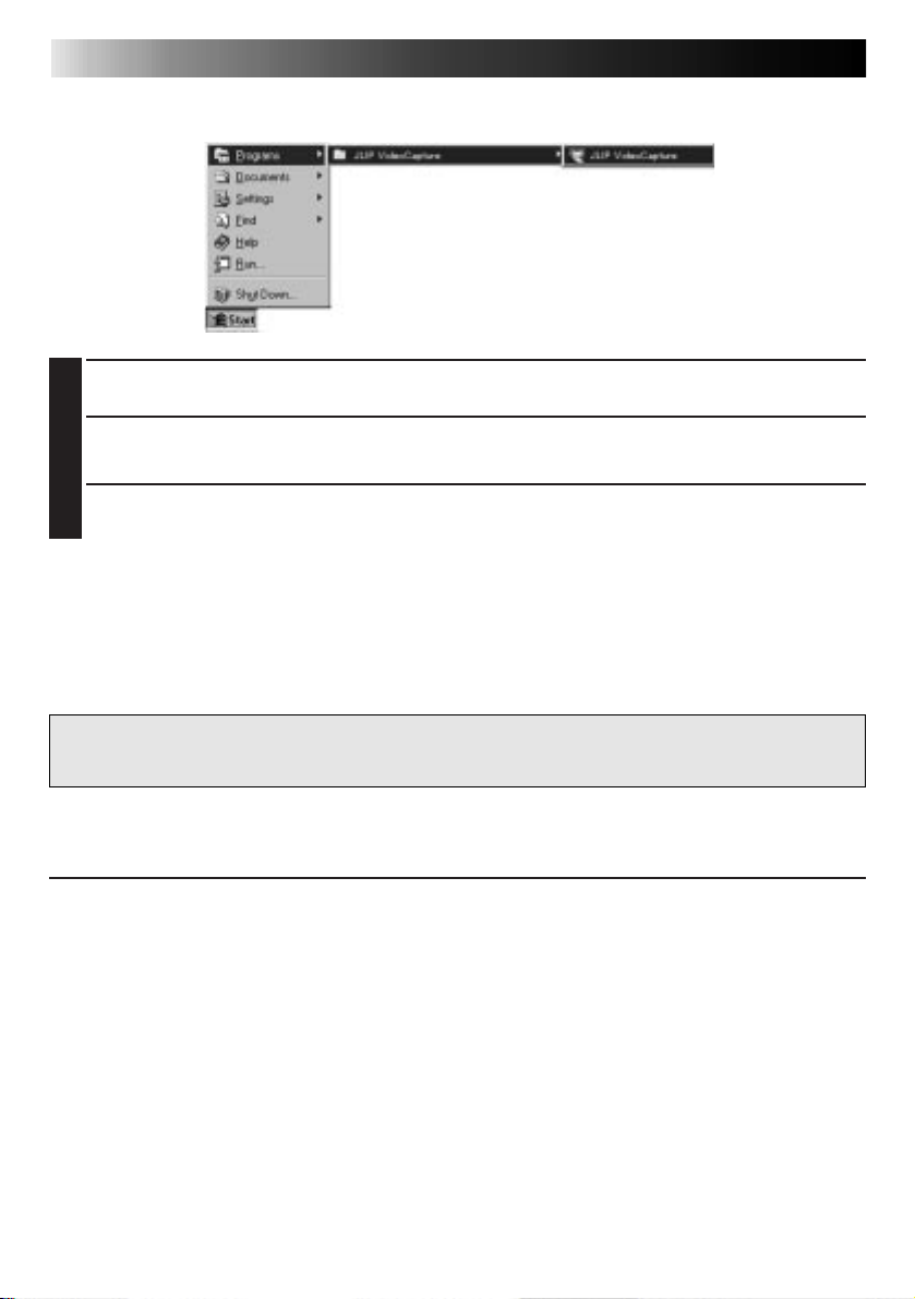
Click Start on the task bar.
2
• The Program menu appears on the screen.
Move the mouse pointer over JLIP Video Capture and click to start the program.
3
• JLIP Video Capture starts up.
NOTE
• Close any other programs running on the PC.
• Disable any programs that run in the background, such as screen savers, e-mail applications, virus checkers, schedulers, etc.
• Turn off file and printer sharing.
CAUTION
• Do not disconnect the video source unit or turn it off while JLIP Video Capture is running.
HOW TO CLOSE THE PROGRAM
Click the Close button or select File — Exit.
Page 7
INITIALIZATION
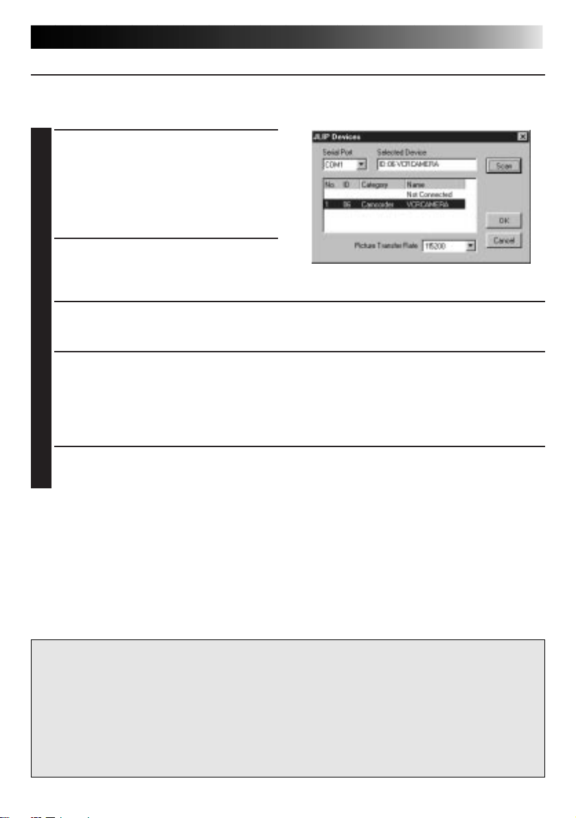
SELECTING THE CONNECTED DEVICE
You can use the JLIP Devices window to select a video source unit connected to one of the
COM ports (RS-232C) after starting up JLIP Video Capture, or when you connect a different
video source unit.
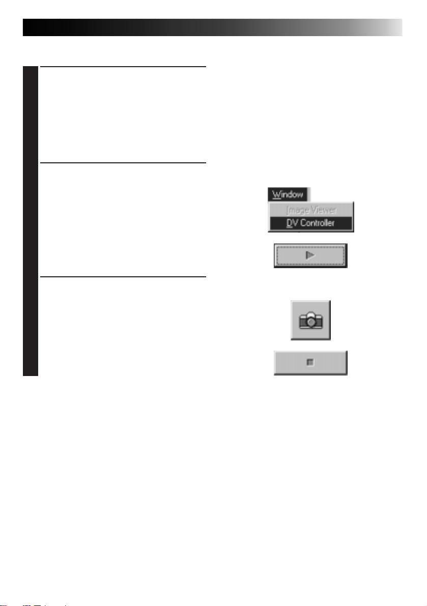
Select Window — DV Controller in the
1
Index window.
• The JLIP Devices window opens.
• You can also select Preferences —
Devices in the DV Controller window
to open the JLIP Devices window.
Select the Serial Port (COM 1 to COM 4).
2
• Select the COM port the video source
unit is connected to.
Click Scan.
3
• When the connected video source unit is detected, its name appears in the window.
Select the Picture Transfer Rate.
4
• Set it to 115200.
• Depending on your PC’s specifications, the software may not function properly when
this speed is selected. If an error occurs during use, set it to a slower rate (38400 or
less).
EN 7
Click OK.
5
• The DV Controller window appears after setting is completed.
NOTE
If the video source unit is not detected, follow the procedures below.
1 Confirmed that the COM port the video source unit is connected to is selected in the JLIP
Devices window.
2 Check the connections.
3 Set the video source unit’s Power Dial to PLAY or PLAY/PC.
4 Click Scan in the JLIP Devices window.
5 If the video source unit appears in the window, click OK (setting is completed).
CAUTION
• If you are using a built-in modem or IrDA, the RS-232C COM port may be occupied. In
this case, click the right button of the mouse to select My Computer, then select Properties
— System Properties — Device Manager. Click Ports (COM & LPT) to confirm which
COM port is available. If all the COM ports are occupied, set the COM port used by the
modem or IrDA driver to Invalid.
• If a USB or Digital Still Camera driver is installed on your PC, you may not be able to use
the RS-232C port.
• Depending on your PC’s specifications, you may need to change the BIOS settings.
Page 8
8 EN
JLIP VIDEO CAPTURE WINDOWS
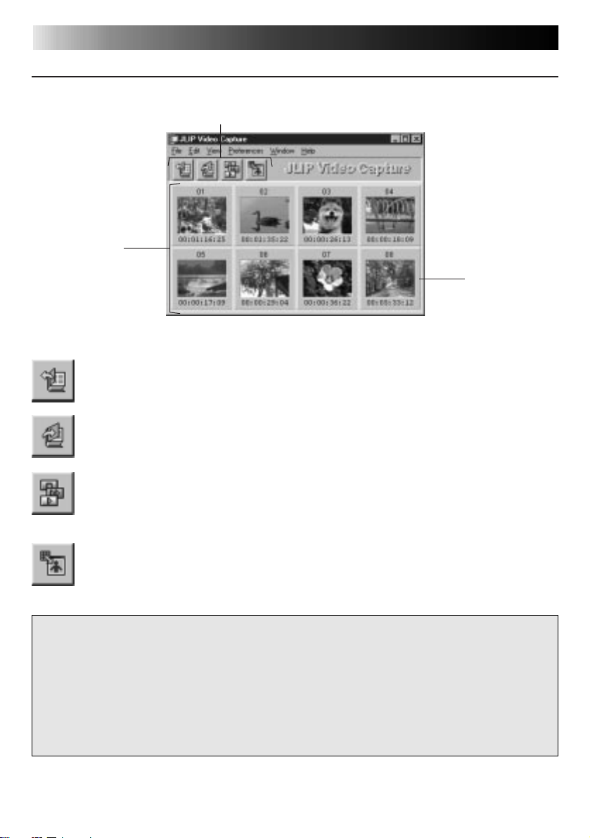
INDEX WINDOW
Index images are displayed as an album in the Index window.
1
2
1
Toolbar
Open button
Opens an album file or image file.
Save Album button
Saves images in the Index window
as an album file.
2
Index display section
The captured images are displayed in this
section.
3
Index image
Each index image consists of a thumbnail
image and its time code.
3
DV Controller button
Opens the DV Controller window
for control of the connected video
source unit from your PC.
Image Viewer button
Opens the Image Viewer window
and displays the captured image at
full size.
CAUTION
• The DV Controller window closes automatically when a slide show is started, or when
Edit — Open Editor or Edit — Copy in Image Viewer is selected.
• When using the Forward/Reverse Frame Advance buttons to control a video source unit
that has no Frame Playback function, the video source unit will initiate slow playback for a
few seconds, then stop. On some video source units, each frame advance may not be the
exact length of a proper frame.
• The DV Controller window may not correspond to the status of the video source unit if a
remote control unit is used to control it.
NOTE
• Each toolbar button function can also be
performed from the menu bar.
• To hide the toolbar, select View —
Toolbar.
Page 9
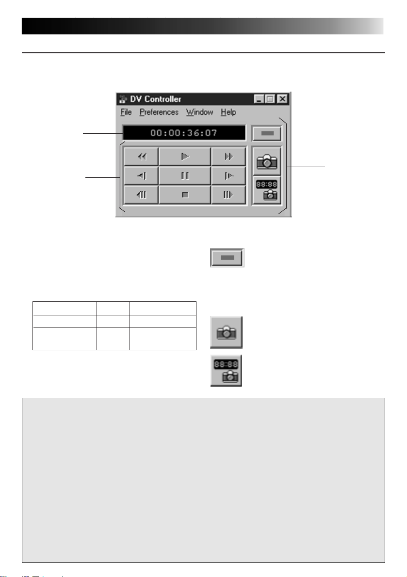
DV CONTROLLER WINDOW
Select Window — DV Controller in the Index window to open the DV Controller window.
This window is used to capture still images from a video source unit.
1
3
2
1
Counter Indicator (Time Code)
The video source unit’s time code is
displayed here.
2
Operation Buttons for Video Source
Unit
Rewind Play Fast Forward
Reverse Slow Pause Forward Slow
Reverse Frame Stop Forward Frame
Advance Advance
3
Operation Buttons
Power button
Displays the power status of the
connected video source unit. Note
that, depending on the video deck
connected, it may not be possible
to turn its power on and off.
Capture button
Captures the desired playback
image.
Automatic Capture button
Controls the playback of the video
source unit and captures specified
playback images.
EN 9
CAUTION
• Use only the operation buttons in the DV Controller window to control the video source
unit. If you operate the video source unit with its own operation buttons, the appearance
of the DV Controller window may not correspond to the status of the video source unit, or
it may cause a malfunction to occur in JLIP Video Capture.
• The DV Controller window may appear to still be operating the video source unit even
after the videocassette automatically stops at the beginning or end of the tape. In this case,
click the Stop button in the DV Controller window before performing another operation.
• If an image is captured in the Pause or Slow Play mode, some noise may appear on the
captured image. In this case, capture the image during normal playback.
• If videotape being used is damaged, some noise may appear in the playback image in the
DV Controller window.
• Automatic Capture cannot be performed in the time code range of 00:00:00:00 and
00:00:30:00 in the DV Controller window.
• Depending on your PC’s or video source unit’s specifications, the DV Controller window
may not function.
Page 10
10 EN
JLIP VIDEO CAPTURE WINDOWS (cont.)
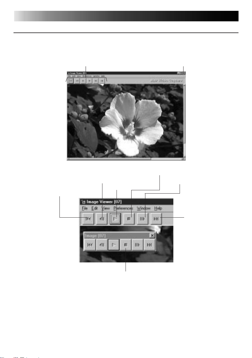
IMAGE VIEWER WINDOW
Select Window — Image Viewer in the Index window to open the Image Viewer window.
This window is used to display images at full size, and to present images in an album as a slide
show.
First Image button
Toolbar
Previous Image button
Slide Show button
Close button
Stop button
Next Image button
Last Image button
Control window
NOTE
• Each toolbar button function can also be performed from the menu bar.
• Clicking the right mouse button in the Image Viewer window brings up a menu of the
toolbar functions.
• Select Window — Button to display a small Control window containing the toolbar
buttons.
• To hide the toolbar, select View — Toolbar.
Page 11
BASIC IMAGE CAPTURE
This section describes basic image capture operations. For more detailed instructions, see
pages 13-15.
Set up your equipment.
EN 11
1
• If using a video camera, insert a
videocassette into it.
•␣ Connect the video source unit to your
PC, and turn both on.
•␣ Start up JLIP Video Capture.
(see page 6)
Start playback.
2
• Click Window — DV Controller to
open the DV Controller window.
• Click the Play button in the DV
Controller window.
Capture the desired image.
3
• Click the Capture button when the
image you want to capture appears.
The image data will be transferred to
your PC.
•␣ When you are finished, click the Stop
button and close the DV Controller
window.
Page 12
12 EN
View the image in the Image Viewer
4
window.
• Double-click the thumbnail image in
the Index window.
• The image is displayed in the Image
Viewer window at its captured size.
• Click the Image Viewer window’s
Close button to return to the Index
window.
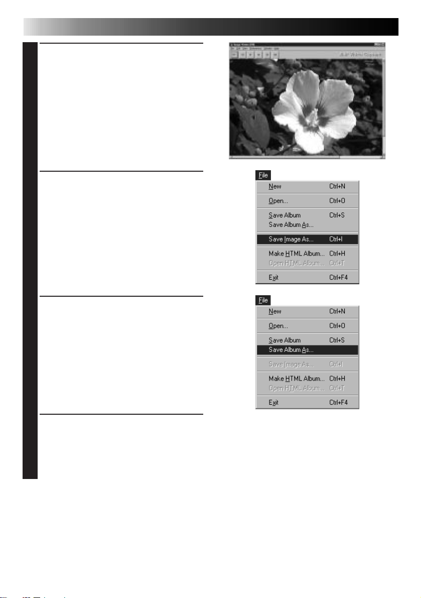
Save the image on your PC’s hard drive.
5
• Click on the thumbnail image in the
Index window to select it, then click
File — Save Image As. For more
details, refer to the Windows
manual or your computer’s manual.
• Enter a file name for the image and
click Save.
Alternatively, you can save multiple
6
images as an album.
BASIC IMAGE CAPTURE (cont.)
®
95/98
• Click File — Save Album As from the
Index window.
• Enter a file name for the album and
click Save.
You can also modify or use images in
7
various ways.
• You can create an HTML album of
images using JLIP Video Capture. (see
page 30)
NOTE
• The following characters cannot be used in file names:
\ / : * ? ” < >
• You can save images in JPEG, Bitmap (BMP) or DVF format. (see pages 20-22)
l
l
Page 13
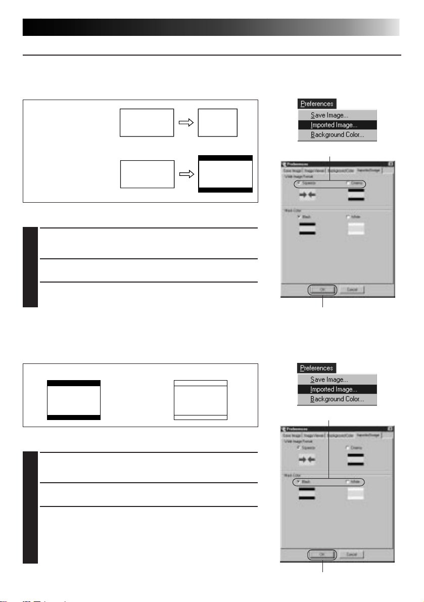
ADVANCED CAPTURE FUNCTIONS
EN 13
IMPORTED IMAGE
Squeeze/Cinema
You can select Squeeze or Cinema when adding wide-screen images (with an aspect ratio of
16:9) to an album.
Squeeze
Squeezes the image’s
aspect ratio from 16:9
to 4:3.
Cinema
Inserts a black or white
mask at the top and
bottom of the image to
convert its aspect ratio
to 4:3.
2
Image Size Preferences
Click Preferences — Imported Image in the Index
1
window.
Select Squeeze or Cinema in Wide Image Format.
2
Click OK.
3
3
Mask Color (Black/White)
You can select the mask color when adding images whose aspect ratio is not 4:3 (except when
Squeeze is selected in Wide Image Format) to an album.
Black White
2
Mask Color Preferences
Click Preferences — Imported Image in the Index
1
window.
Select Black or White in Mask Color.
2
Click OK.
3
3
Page 14
14 EN
ADVANCED CAPTURE FUNCTIONS (cont.)
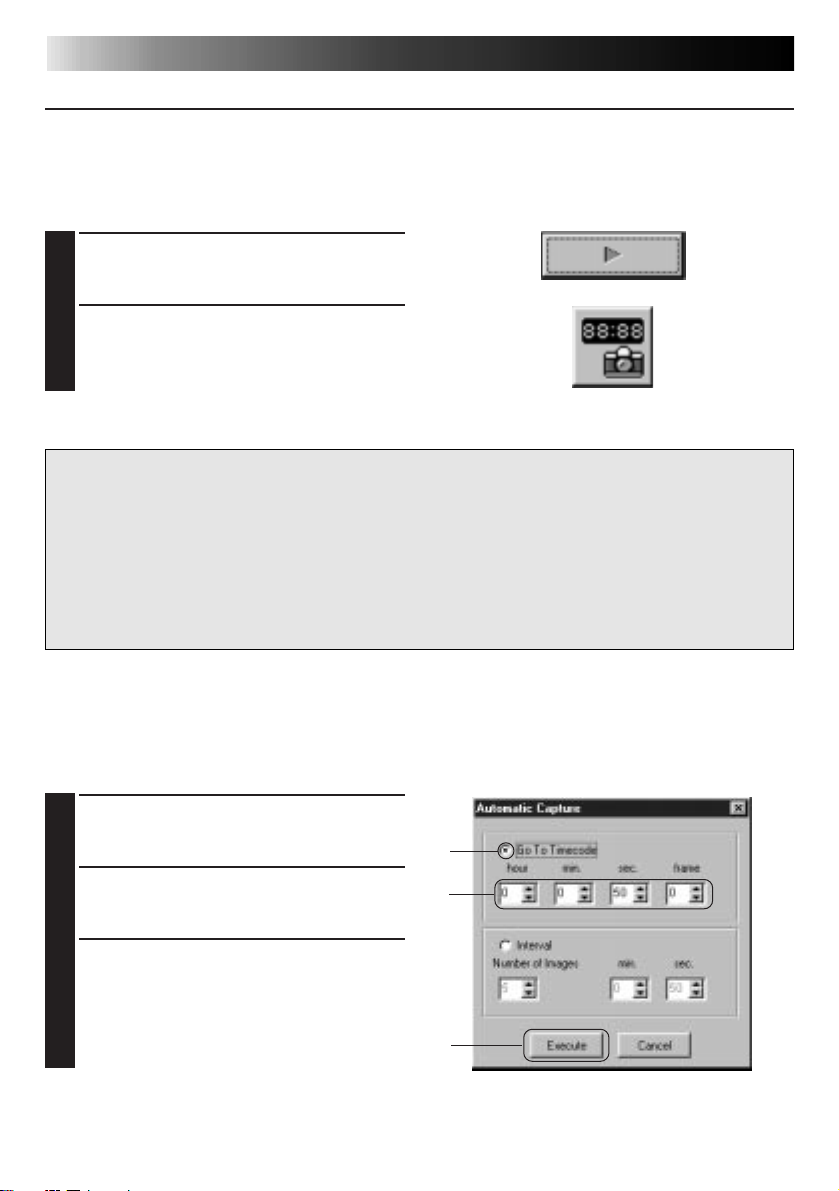
AUTOMATIC CAPTURE
You can capture images automatically according to your preferences.
Automatic Capture cannot be performed in the time code range of 00:00:00:00 and
00:00:30:00.
Automatic Capture Preferences
Click the Play button in the DV
1
Controller window.
Click the Automatic Capture button.
2
CAUTION
• Depending your PC’s specifications and operating environment, the points where images
are captured may not match what was set in the preferences.
• During automatic capture, do not move the DV Controller window, change its size,
operate its scroll bars or access the menu, otherwise it may cause the points where images
are captured to not match what was set in the preferences.
• If the videotape is damaged, the points where images are captured may not match what
was set in the preferences.
• Automatic capture may not function properly if portions of the videotape are unrecorded.
Go To Time Code
You can specify the precise time code at which to capture an image. This function is useful for
capturing images next to ones already captured.
Select Go To Time Code in the
1
Automatic Capture window.
1
Select the hour, minute, second and
2
frame to go to.
Click Execute.
2
3
3
Page 15
EN 15
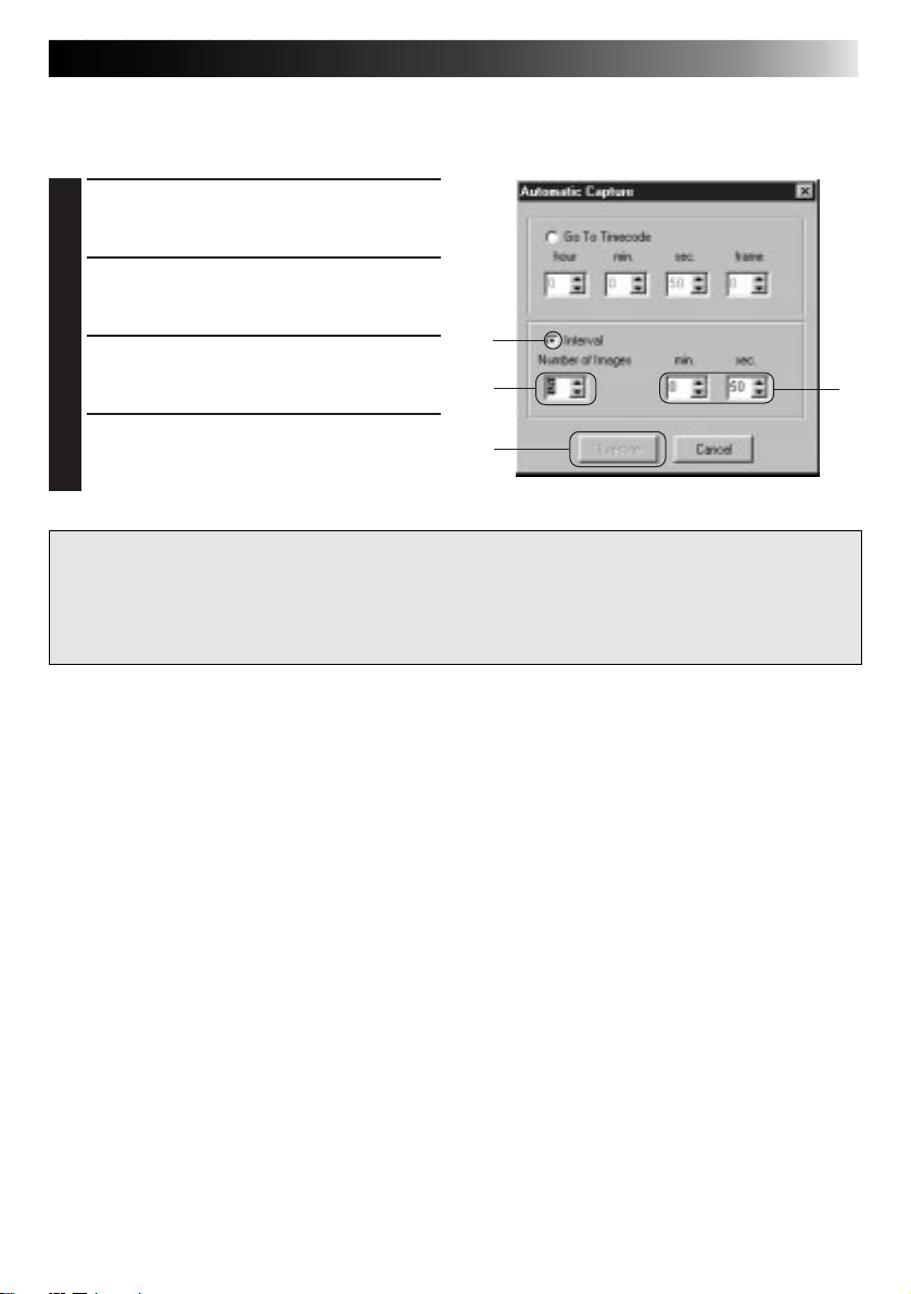
Interval
You can capture images at specified intervals. This function is useful for summarizing the
contents of a tape, or for watching time-lapse movies using the slide show.
Select Interval in the Automatic Capture
1
window.
Select the number of images to be
2
captured.
Select the length of the interval (in
3
minutes and seconds).
Click Execute.
4
CAUTION
• Automatic capture stops when the number of images in the Index window reaches 99 or
the videotape ends.
• This function doesn’t work if there is no time code recorded on the videotape, or if the
recording time is shorter than 1 minute.
1
2
4
3
Page 16
16 EN
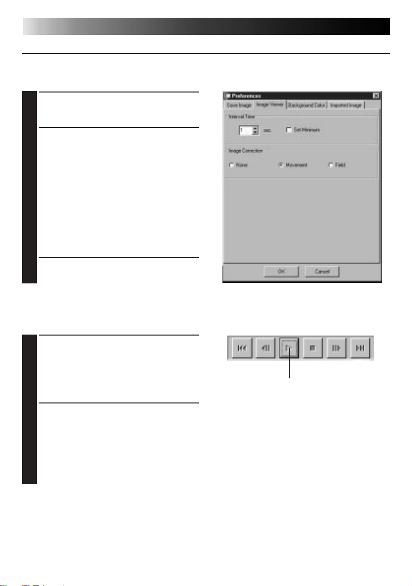
SLIDE SHOW
Slide Show Preferences
You can select the display interval during a slide show.
Select Preferences — Image Viewer
1
from the Image Viewer window.
Make sure the Set Minimum box is
2
unchecked, and select the interval (in
seconds) between images.
• Check the Set Minimum box when
you want to display images one after
another quickly.
•␣ You can select from 0 to 30 seconds.
The actual interval is equal to the sum
of the selected time plus the time it
takes your PC to load and display the
images.
Click OK.
3
Slide Show Operation
You can view images in the Index window as a slide show.
VIEWING IMAGES
Click the Slide Show button in the Image
1
Viewer window, or select View — Slide
Show.
• The slide show starts.
To stop the slide show, click the image
2
currently being displayed, or click the
Stop button in the Image Viewer
window.
• The slide show stops automatically
when a menu is accessed or a button
is clicked.
NOTE
• You can also start up the slide show by clicking the right mouse button in the Image Viewer
window to bring up a menu of the toolbar functions.
1
Page 17
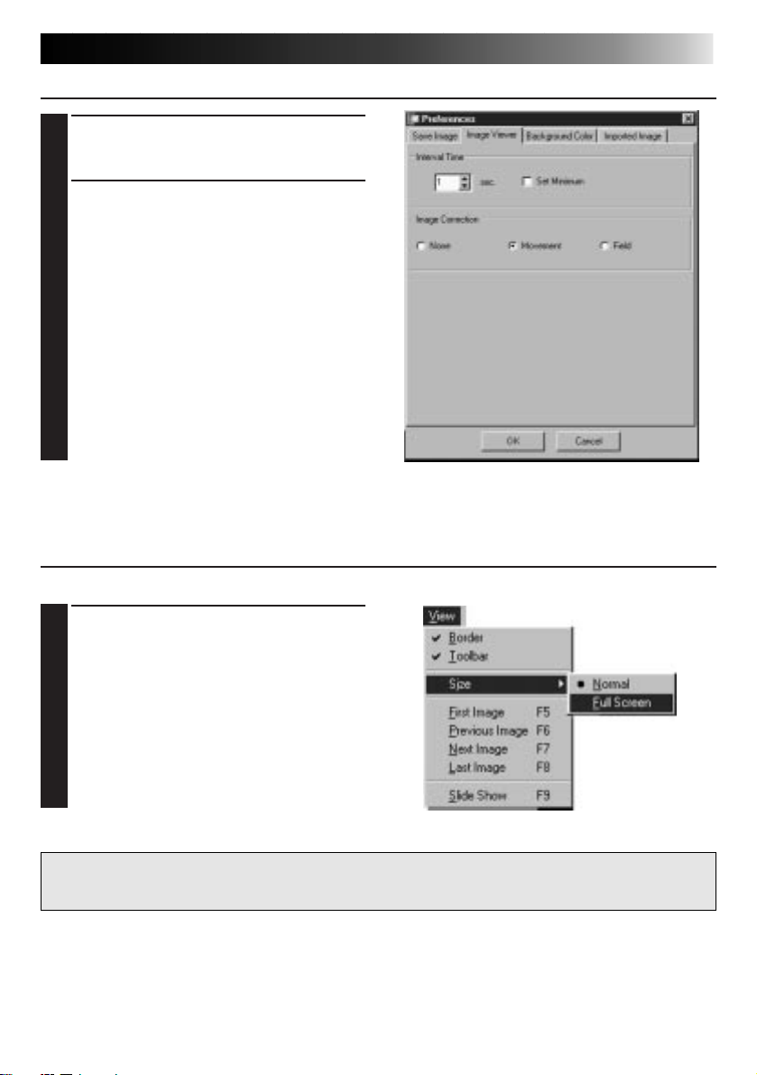
IMAGE CORRECTION
Select Preferences — Image Viewer in
1
the Image Viewer window.
When displaying images captured from
2
a fast action sequence, select Movement
in Image Correction.
• Images in the displayed album will be
corrected for camera shake.
• To use less memory, select Field.
• To use no image correction, select
None.
DISPLAY SIZE
You can select between normal and full-screen display.
EN 17
For full-screen display, select View —
1
Size — Full Screen in the Image Viewer
window.
• For normal display, select View —
Size — Normal.
CAUTION
• When your monitor resolution is 640 x 480 pixels, Full Screen cannot be selected.
Page 18

18 EN
VIEWING IMAGES (cont.)
IMAGE VIEWER APPEARANCE
You can toggle the display of the border (window frame and menu bar) and toolbar in the
Image Viewer window.
Hiding the Border
Select View — Border in the Image
1
Viewer window to uncheck it. The
window frame and menu bar disappear.
•␣ You can toggle the border display by
clicking the right mouse button in the
Image Viewer window to bring up the
View menu.
Hiding the Toolbar
Select View — Toolbar in the Image
1
Viewer window to uncheck it. The
toolbar disappears and a small Control
window containing the toolbar buttons
appears.
• Perform this step again to make the
toolbar reappear.
•␣ You can also toggle the toolbar display
by clicking the right mouse button in
the Image Viewer window to bring up
the View menu.
• You can also select Window — Button
in the Image Viewer window to make
the Control window containing the
toolbar buttons appear.
Page 19

SELECTING A BACKGROUND COLOR
You can select the background color in the Index window.
Select Preferences — Background Color
1
in the Index window or Image Viewer
window.
Select the desired background color.
2
Click OK.
3
EN 19
Page 20

20 EN
You can select JPEG, Bitmap (BMP) or DVF format for saving images, and adjust their settings.
CHANGING THE IMAGE FORMAT
JPEG Preferences
JPEG images are saved with a high compression rate, making them ideal for Internet web pages.
Select Preferences — Save Image in the
1
Index window or Image Viewer window.
Select JPEG in Image Format.
2
Select an image size in Image Size.
3
• If the video footage was shot in the
wide-screen mode, the image width is
greater than in the standard mode.
Image width in the widescreen mode
is shown in brackets.
Select the JPEG image quality using the
4
JPEG Quality slider.
Select the type of image correction to
5
use by selecting either None, Movement
or Field in Image Correction.
• Movement: Image blur caused by
camera shake is corrected.
• Field: Saves images to the hard drive
faster than when Movement is
selected.
You can preview your settings by
6
clicking Preview. When you are
finished, click OK.
Save images as desired. (see pages 12
7
and 23)
NOTE
• Moving the JPEG Quality slider to the right lowers the compression rate, resulting in higher
image quality and increased file size. Moving the JPEG Quality slider to the left raises the
compression rate, resulting in lower image quality and decreased file size.
• By using compression, you can fit more images onto a floppy disk, hard disk, etc.
Page 21

EN 21
Bitmap Preferences
Bitmap (BMP) is the standard format used by Windows®, and is supported by many software
applications.
Select Preferences — Save Image in the
1
Index window or Image Viewer window.
Select Bitmap in Image Format.
2
Select an image size in Image Size.
3
• If the video footage was shot in the
wide-screen mode, the image width is
greater than in the standard mode.
Image width in the widescreen mode
is shown in brackets.
Select the number of colors in Bitmap
4
Colors.
Select the type of image correction to
5
use by selecting either None, Movement
or Field in Image Correction.
• Movement: Image blur caused by
camera shake is corrected.
• Field: Saves images to the hard drive
faster than when Movement is
selected.
You can preview your settings by
6
clicking Preview. When you are
finished, click OK.
Save images as desired. (see pages 12
7
and 23)
Page 22

22 EN
DVF Preferences
DVF is the native format for storing still images from digital videotape. DVF images are saved
without changing the data, so there is no loss of quality.
Select Preferences — Save Image in the
1
Index window or Image Viewer window.
Select DVF in Image Format.
CHANGING THE IMAGE FORMAT (cont.)
2
Click OK.
3
Save images as desired. (see pages 12
4
and 23)
Page 23

SAVING AN IMAGE
EN 23
SAVING INDEX IMAGES
You can save index images separately from their album file. Before saving an image, set the
desired image format and preferences. (see pages 20-22)
Click the desired index image in the
1
Index window.
• To select multiple index images, hold
down the Ctrl key and click each
index image that you wish to save.
• To select multiple sequential index
images, click the first index image.
Then, hold down the Shift key and
click the last index image that you
wish to save.
Select File — Save Image As.
2
Enter a file name and click Save.
3
• If you click Yes when asked “Save all
images with this default name?”, an
ID number will be appended to the
selected default name.
Page 24

24 EN
SAVING AN IMAGE (cont.)
SAVING IMAGES IN THE IMAGE VIEWER WINDOW
Select File — Save Image As in the
1
Image Viewer window.
Enter a file name and click Save.
2
ADDING IMAGE FILES TO THE INDEX WINDOW
You can add JPEG, Bitmap (BMP) and DVF images to the Index window.
• To add images to the Index window directly from a video source unit, see page 11.
Select File — Open.
1
Select the desired image format in the
2
Files of type field.
Select the desired file and click Open.
3
• You can select several files at a time.
NOTE
• You can also drag & drop images into the Index window from folders or Windows Explorer.
For more details, refer to the Windows
• When a JPEG or BMP image is added to the Index window, no time code is displayed.
• When any-sized JPEG or BMP image is added to the Index window, it is automatically
resized to 720 x 480 (NTSC*
• An image whose aspect ratio is not 4:3 will be automatically resized to 4:3 when it is added
to the Index window or saved.
*1: NTSC (National Television System Committee) is the video system used mainly in North
America and Japan.
*2: PAL (Phase Alternation by Line) is the video system used mainly in Western Europe and
Asia.
1
) or 720 x 576 (PAL*2) pixels.
®
95/98 manual or your computer’s manual.
Page 25

SAVING IMAGES AS AN ALBUM
SAVING IMAGES AS AN ALBUM
You can save the images in the Index window as an album.
To create a new album, click the Save
1
Album button on the toolbar in the
Index window.
Enter the desired file name and click
2
Save.
• To save a modified album, select File
— Save Album.
COPYING AN INDEX IMAGE
You can copy images within the Index window.
Click the image you wish to copy.
1
While holding down the Ctrl key, click
2
and hold down the left mouse button on
the index image you wish to copy, then
drag it to the desired position.
EN 25
Page 26

26 EN
DELETING AN INDEX IMAGE
You can delete images in the Index window.
Click the image you wish to
1
delete.
• To select multiple index images, hold
down the Ctrl key and click each
index image that you wish to delete.
• To select multiple sequential index
images, click the first index image.
Then, hold down the Shift key and
click the last index image that you
wish to save.
Select Edit — Delete.
2
• Alternatively, you can press the Del
key.
At the Delete (number) Image(s)?
3
prompt, click Yes.
DELETING AN INDEX IMAGE
MOVING AN INDEX IMAGE
You can move images within the Index window.
Click the image you wish to move.
1
Click and hold down the left mouse
2
button on the index image you wish to
move, then drag it to the desired
position.
Page 27

ADDING IMAGES TO AN ALBUM
EN 27
ADDING IMAGES TO AN ALBUM
You can add images to an album by capturing them from a video source unit or by importing
them from your PC’s hard disk (JPEG/Bitmap/DVF).
To capture images from a video source
1
unit...
Open the album you wish to add images
to, then capture the desired images (see
pages 11, 14-15).
To import images from your PC’s hard
disk...
Drag the desired image files to the Index
window. Each file is added to the end of
the index.
NOTE
• When a JPEG or Bitmap image is added
to the Index window, no time code is
displayed.
• When a JPEG or Bitmap image is added
to the Index window, it is automatically
resized to 720 x 480 (NTSC) or 768 x
576 (PAL) pixels.
Page 28

28 EN
COPYING AN IMAGE
COPYING AN IMAGE INTO THE CLIPBOARD
You can copy an image displayed in the Image Viewer window into the clipboard for use in
another application.
Select Edit — Copy.
1
• Alternatively, you can press Ctrl-C.
NOTE
• Image data copied into the clipboard is resized to 640 x 480 (standard) or 848 x 480
(wide) pixels.
PASTING AN IMAGE FROM THE CLIPBOARD
You can paste an image from the clipboard into another application.
In the desired application (such as an
1
image editing program), press Ctrl-V to
paste the image from the clipboard.
• For more details, refer to the application’s instructions.
NOTE
• This function may not work if too many images are displayed on-screen at a time.
• Image data copied into the clipboard is resized to 640 x 480 (standard) or 848 x 480
(wide) pixels.
• Close JLIP Video Capture after loading the other application. If both programs are running
at the same time, your PC may become unstable due to heavy memory consumption.
Page 29

EDITING AN IMAGE
You can load an external image editor application to modify an image. Before using this
function, an image editor application must be installed.
Select Edit — Open Editor in the Image
1
Viewer window.
EN 29
CAUTION
• Refer to the image editor application’s instructions for details about its operation.
• The most recently installed image editor application starts up when Open Editor is
selected. If you wish to link to a different image editor application, refer to Help in Windows
• This function uses linking to load the proper application. Depending on the settings on
your PC however, a different application may load instead.
• Select the image format to be used in Preferences — Save Image.
• If DVF format is selected, this function is unavailable. Select JPEG or Bitmap in
Preferences — Save Image to use this function.
• Close JLIP Video Capture after loading the other application. If both programs are running
at the same time, your PC may become unstable due to heavy memory consumption.
®
.
Page 30

30 EN
You can save images in the Index window as an HTML album, which can then be viewed
using an Internet browser.
CREATING AN HTML ALBUM
SAVING IMAGES IN HTML FORMAT
Select the images you would like to save
1
in the Index window. (see page 23)
• If no index images are selected, all of
them will be saved as an HTML
album.
Select File — Make HTML Album.
2
Enter a name for the HTML file and click
3
Save.
Enter a title for the HTML album in the
4
Title Input field and click OK.
• An HTML file and a folder containing
the individual images are saved. The
HTML file and folder use the same
name.
CAUTION
• Images saved in an HTML album are converted to JPEG format with a quality of 75.
• The background color of the HTML album is the same as that of the Index window when it
is set to Default or User Defined.
• JLIP Video Capture cannot open an HTML album.
• When moving an HTML file and folder, make sure they are kept in the same place relative
to each other. The HTML file uses a relative directory path to load the images.
VIEWING THE HTML ALBUM
Select File — Open HTML Album to
1
open the HTML album in an Internet
browser.
• HTML albums may also be posted on
the Internet as web pages.
Page 31

TROUBLESHOOTING
EN 31
Problem Cause Page
unit cannot be detected.
The COM port cannot be
set.
• Confirm that your video source unit is
connected to the AC adapter correctly.
• Confirm that the cable is connected to your
PC and video source unit correctly.
• Turn on the power of the video source unit
before starting up JLIP Video Capture.
• If it is still not detected after clicking Scan in
the JLIP Devices window two or three times,
try turning off your PC and video source unit.
Confirm the connection between them then
turn them both back on.
•␣ Confirm that the JLIP Devices window is
operating properly after clicking Scan.
• If you are using a built-in modem or IrDA,
the RS-232C COM port may be occupied. In
this case, click the right button of the mouse
to select My Computer, then select
Properties — System Properties — Device
Manager. Click Ports (COM & LPT) to
confirm which COM port is available. If all
the COM ports are occupied, set the COM
port used by the modem or IrDA driver to
Invalid.
• If a USB or Digital Still Camera driver is
installed on your PC, you may not be able to
use the RS-232C port.
• Depending on your PC’s specifications, you
may need to change the BIOS settings.
6, 7The connected video source
Page 32

32 EN
TROUBLESHOOTNG (cont.)
Problem Cause Page
function correctly.
• This function may not operate correctly
sometimes depending on your PC’s
specifications and operating environment.
• This may occur␣ if you move the DV
Controller window, operate its scroll bars or
perform a file operation while capturing
images.
•␣ This may occur if correct data is not being
transmitted due to damage on the videotape.
•␣ This may occur if a tape recorded in the LP
mode is played back on a different video
source unit. Play videotapes using the video
source unit they were recorded on.
•␣ There may be software running in the
background. Confirm that there are no
programs running in the background that
may be using the processor at the same time
as JLIP Video Capture.
6, 9, 11,14Automatic capture does not
NOTE
When using a laptop PC, operation may be interrupted by a warning when the battery is
nearly exhausted.
• If there is software which monitors the status of the battery running in the StartUp folder...
Close the application, or delete/move its icon from the StartUp folder and reboot your PC.
• If you are using your PC’s power management function...
Click the right button to select My Computer, then select Properties —
System Properties — Device Manager — System Devices — Advanced Power Management Support. Follow the appropriate procedure below.
For Windows
mark (u) next to it disappears).
For Windows
®
95, click Settings and deselect Enable power management support (the check
®
98, select Disable in this hardware profile (a check mark (u) appears next to it).
Page 33

EN 33
JLIP VIDEO PRODUCER
SOFTWARE SECTION
You can find the latest information (in English)
on the provided software program at our World
Wide Web Server.
http://www.jvc-victor.co.jp/english/index-e.html
Page 34

34 EN
STARTING AND EXITING JLIP VIDEO PRODUCER
Starting JLIP Video Producer
Connect the video source unit to the PC
1
using the JLIP connection cable, then
turn the video source unit on.
Turn on your PC and start up Windows®.
2
Click Start on the task bar.
3
•The Program menu appears on the
screen.
Move the mouse pointer over JLIP
4
VIDEO PRODUCER and click to start the
program.
•JLIP Video Producer starts up.
NOTES:
•
Exit all other software applications before
starting JLIP Video Producer.
•
Suspend the operation of any other
software applications that periodically start
at a given interval or time. (This includes
screen savers, e-mail software,
communications software, virus checkers,
schedulers and so on.)
•
Cancel network settings for any printers or
folders on harddisks that are connected to
or built into the PC and that are being
shared over a network.
•
Do not plug or unplug the PC connection
cable or turn off power to video equipment
while using Video Producer as doing so
may cause the PC to malfunction.
Exiting JLIP Video Producer
Select File — Exit on the JLIP Video
1
Producer window. When the
confirmation screen appears, click Yes.
Page 35

Listbox
Initializing JLIP Devices
Select Preferences — JLIP Devices.
1
Select the serial port to which the device
is connected and click Scan.
Select the player to be used by clicking
2
on it in the listbox and then click Select.
•You do not need to perform the
operation in step 2 when only one
player is connected.
Select the recorder deck to be used by
3
clicking on it in the listbox and then
click Select.
•Select Use Edit Terminal on the screen
when using a JVC Video deck that has a
remote pause terminal but no JLIP
terminal or a deck from another
manufacturer.
Click OK.
4
4
EN 35
Page 36

36 EN
JLIP VIDEO PRODUCER WINDOW BUTTONS AND DISPLAYS
JLIP VIDEO PRODUCER WINDOW
1
234
5
CONTROLLER
67 8
)
(
*
&
^
9
0
!
@#$%
Page 37

1 P.AE/Effect buttons
• Selects one of the 5 P.AE/Effects
available per programmed scene.
• To cancel the selected effect, click the
EC (Effect Clear) button.
2 Fade/Wipe Effect buttons
• Selects one of the 7 Picture Wipes or 10
Fades/Wipes available per scene
transition.
• To cancel the selected effect, click the
TC (Transition Clear) button.
3 Elapsed Time
• Displays the total elapsed time of all the
programmed scenes.
4 Button for Opening the Controller
Window
• Displays the controller.
• Can be displayed even when selecting
the menu Window — Controller.
5 Program list
• Displays the following setting
information beginning from the left:
Scene number, In point, P.AE/Effect, Out
point, Fade/Wipe Effect, Duration Time
Counter, and Memo.
• Up to 99 programs can be set per file for
scenes specified by an In and Out point.
6 ID number
• Displays the video source unit’s ID
number.
• An ID number can be clicked to display
the JLIP Devices dialog box as well as
when switching the serial port or
performing JLIP devices scanning.
7 Edit Indicator
• In Normal mode, the deck being
operated is displayed in green.
• In Edit mode, both deck indicators light
(Player: Green, Recorder: Red) and an
arrow also lights.
• The recorder lights red between the In
point and Out point while the recorder
is actually recording.
• Clicking on either deck selects the one
to be operated.
EN 37
8 Tape counter display
• Displays the current tape position.
ex.
00: 01: 45: 10
(Hours : Minutes : Seconds : Frames)
• The digital camera’s counter uses a
drop-frame system.
9 Close button
• Close the controller window.
0 Edit buttons
AB
A. Edit Standby button
• The player is put into Pause mode for
the Syncro Edit pre-roll time already set
on the Options dialog box (see
page 52).
• This button is used when VCRs not
compatible with this editing system and
performing manual editing.
• This button cannot be clicked when the
counter reads less than 00:00:30:00.
• This button cannot be clicked when the
player is not paused.
B. Syncro Edit button
• After going into Playback-Pause mode at
the In point of the recorder and player,
clicking this button rewinds both decks
by the pre-roll amount and executes the
first event.
• Since no Out point is specified, the
Syncro Edit is stopped using Stop.
• This button cannot be clicked when the
counter reads less than 00:00:30:00.
• This button cannot be clicked when the
player is not paused.
C. Select Player/Recorder button
• Selects the deck to be operated. The
player is forcibly selected when no
recorder is connected to the JLIP.
• This button cannot be clicked when
there is no JLIP recording equipment.
C
Page 38

38 EN
JLIP VIDEO PRODUCER WINDOW BUTTONS AND DISPLAYS (cont.)
! Jog/Shuttle
Jog/Shuttle Operation buttons
Click these buttons to perform Jog/Shuttle
operations.
Jog Dial Select button
Jog Dial mode is
selected when the
inner ring is lit.
Shuttle Dial Select button
Shuttle Dial mode is selected when the outer
ring is lit.
Jog Dial Lamp (Inner lamp)/Jog Dial
• Jog Dial mode is selected when the jog
dial lamp is lit by clicking with the
mouse.
• It is possible to advance frames by
clicking with the mouse on the left
(reverse) or right (forward) arrows.
• The deck can be operated at this time
using the number keys.
Shuttle Lamp (Outer ring)/Shuttle Ring
• Shuttle mode is selected when the
shuttle dial lamp is lit by clicking with
the mouse.
• Slow Playback, Playback, and Fast
Forward Playback depending on the left
(reverse) or right (forward) arrows that
are clicked.
• The deck can be operated at this time
using the number keys.
PC's Ten-key assignments for Jog/Shuttle
<Jog Mode>
[2]: Playback
[4]: Frame reverse
[6]: Frame advance
[8]: Jog/Shuttle Select & Pause
[•]: Stop
<Shuttle Mode>
[2]: Playback
[4]: Accelerates one level in the rewind
direction, or decelerates one level in
the fast forward direction.
[6]: Accelerates one level in the fast
forward direction, or decelerates one
level in the rewind direction.
[8]: Jog/Shuttle Select & Pause
[•]: Stop
@ Tape Operation buttons
• These buttons operate the video camera
and recorder.
• For slow playback, click Pause and then
Slow.
• For frame advance playback, click
Pause and then Frame Advance.
• A lock lid is attached to the Record
button. This lid must be clicked to open
before using it.
BCDE
A
K
J
FGHI
A. Recording button
B. Reverse Frame Advance button
C. Pause button
D. Forward Frame Advance button
E. Forward Slow button
F. Stop button
G. Fast Forward/Fast Forward Search
button
H. Playback button
I. Rewind/Rewind Search button
J. Eject button
K. Reverse Slow button
# Review button
• This button operates the recorder to
playback video after editing. Only one
event is played back when using Syncro
Edit, while all programs are played back
when Auto Edit has been executed.
• This button does not function when the
recorder is not connected to the JLIP.
• This button cannot be clicked when not
even one Auto Edit has been executed
since startup.
Page 39

$ Preview button
• Playback the video from the In point to
Out point specified for a program.
• Recording does not result from clicking
this button.
• The PC emits a sound when the
application is started and exited.
• When using a camera that includes
transition functions such as wipe, the
area before the In point and after Out
point appears masked. This allows
accurate confirmation of the video
location to be edited. (This operation is
not possible with some models.)
• This button cannot be clicked when
several scenes are selected.
% Goto button
• Clicking this button causes the deck to
automatically locate the time code
specified in the program list (In point)
and puts the deck in Playback-Pause
mode.
• Only the player can be operated.
^ Auto Edit button
• Playback all scenes in order of Scene
number.
• Since a lock lid is usually attached, click
this button only after opening the lid by
clicking.
• Editing automatically starts once the
recorder is connected and put into
Pause mode.
& Program Modification button
When making fine modifications to a
program, the In point and Out point are
specified using this button after the Scene
number is specified using the Program Select
buttons. Various fine modifications are made
with Trim+/–.
ABC
D
EN 39
A. In Point button
• This button selects the time code for the
In point and displays it in red.
• Fine modification of the time code
for the In point can be done using
Trim+/–.
• Clicking Goto after this button causes
the deck to automatically locate the In
point and puts the deck in PlaybackPause mode.
• This button cannot be clicked when
several scenes have been selected.
B. Out Point button
• This button selects the time code for the
Out point and displays it in red.
• Fine modification of the time code for
the Out point can be done using
Trim+/–.
• This button cannot be clicked when
several scenes have been selected.
C. Trim buttons
These buttons are used to make fine
modifications to the time code of the In
point and Out point specified for the
program.
Trim+: Increases time data by one frame.
Trim–: Decreases time data by one frame.
• This button cannot be clicked when an
In point or Out point is not selected.
D. Modify Edit Points button
This button is used when making fine
modifications to the scene in the program
list currently selected.
• It is also possible to open the Modify
Edit Points dialog box and make fine
modifications to In point, Out point,
tape change and memo.
• The Modify Edit Points dialog box can
also be opened by double clicking on
the Scene number.
• This button cannot be clicked when
several scenes have been selected.
Page 40

40 EN
JLIP VIDEO PRODUCER WINDOW BUTTONS AND DISPLAYS (cont.)
* Entry button
This button is used to enter the current
counter value for the In point and then Out
point each time it is clicked.
• This button is for specifying the In point
and Out point for each scene.
• Clicking Entry after clicking a button
other than Bottom of Scene of the
Program Select buttons will add a new
program to the next number after the
current position. The Scene number for
programs beyond the current one are
each increased by one and pushed
toward the back.
• This button cannot be clicked when the
counter reads less than 00:00:30:00.
( Program Select buttons
Program selection is also possible by clicking
on a Scene number in the program list.
Editing Method when Using an Editing
Deck other than JLIP
1. Locate the In point using the player
connected to the JLIP and put it in
Playback-Pause mode.
2. Click Edit Standby.
3. Locate the In point of the recorder being
operated by other than JLIP and put it in
Record-Pause mode.
4. Simultaneously press the Playback button
of the player and the Recording Start
button of the recorder.
5. Stop recording once the Out point of the
player has been passed.
Please see the instruction manual for the
recorder for details on how to put a deck into
Recording-Pause mode.
A
A. Bottom of Scene button
• Clicking this button instantly moves the
selected position in the program list to
the end of the list.
• This is useful when there are many
programs.
B. Next Scene button
• This button moves the selected position
in the program down by one.
C. Previous Scene button
• This button moves the selected position
in the program up by one.
BC
) Scene Number
• This displays the currently selected
number in the program list.
NOTE:
If you need the JLIP Video Producer Help
window, select Help — Contents.
Page 41

BASIC OPERATIONS
Entry
Operating the video source unit
Set the video source unit to the Play
1
mode and insert a recorded tape.
Click ©.
2
•The playback picture appears on the TV
monitor.
Setting in/out points
To set In/Out points, click Entry at the
1
beginning and end of the scene you want
to dub.
•Set In/Out points so that the Out point
comes after the In point.
•If a scene has no Out point, program
playback and dubbing will be disabled
for that scene.
•If you set In point at the beginning of
the tape or if you set Out point at the
end of the tape, editing may not
function properly. If this happens,
change previously registered In/Out
points slightly and try setting them
again.
•The counters of digital video cameras
cannot be reset.
•In points must have a counter value of
00:00:30:00 or later.
•Some values cannot be set due to dropframe counters.
EN 41
Page 42

42 EN
Preview
BASIC OPERATIONS (cont.)
Playing back one programmed scene
Click on the line where the In/Out points
1
you want to preview are displayed to
highlight that line.
Click Preview.
2
•The video source unit locates the scene
by going to a point prior to the In point,
then starts playback at the In point.
Playback stops after the Out point is
passed.
Auto Edit
Playing back all programmed scenes
Click Auto Edit.
1
•The video source unit plays back
scenes in numerical order and stops
immediately after the last scene’s Out
point.
NOTES:
•
If Preview or Auto Edit is clicked at the end
of the tape, the video source unit will not
function properly.
•
If the source tape has any blank portions on
it, scenes will not be edited properly.
•
If using a VCR with JLIP terminal as a
recording device, click Auto Edit without
inserting a video cassette.
Page 43

EN 43
Dubbing
You can record all programmed scenes onto
a tape in the recorder.
Make sure there is an erase protection
1
tab on the tape. Insert it into the
recording deck and set the recording
deck to the Record-Pause mode.
Click Auto Edit.
2
When editing stops, the video source
unit enters the Stop mode and the
recording deck enters the Record-Pause
mode.
•When "Tape Change" occurs during
dubbing, editing will stop and a
message requesting tape change will
appear. Change the tape and click OK.
Stop the recorder.
3
Page 44

44 EN
BASIC OPERATIONS (cont.)
Selecting a P.AE/Effect
There are 5 P.AE/Effects available to spice up
programmed scenes. You can select only one
effect per programmed scene.
Click on the scene where you want to
1
use a P.AE/Effect.
Click the desired P.AE/Effect button. The
2
selected effect indication is displayed to
the right of the In point.
To cancel the selected P.AE/Effect . . .
Click on the scene which has the effect
you want to cancel, then click the EC
(Effect Clear) button.
NOTE:
If you use the Sepia or Monotone P.AE/
Effects, you cannot use the Dissolve or Black
& White Fader Fade/Wipe Effects.
Selecting a Fade/Wipe Effect
There are 17 Fades/Wipes available for scene
transitions.
Click on the scene where you want to
1
use a Fade/Wipe.
Click the desired Fade/Wipe Effect
2
button.
The selected effect indication is dis-
played to the right of the Out point.
•The Fade/Wipe is executed between the
selected scene (the one clicked) and
the following one.
To set a Fade/Wipe Effect at the editing
start point . . .
Click scene 00 or the tape changing
scene, and then select the desired Fade/
Wipe Effect.
To cancel the selected Fade/Wipe
Effect . . .
Click on the scene which has the effect
you want to cancel, then click the TC
(Transition Clear) button.
NOTE:
Fade/Wipe Effects using video images cannot
be set for scene 00 or tape changing scenes.
Page 45

TC
P.AE/Effect and Fade/Wipe Effect buttons
EN 45
P.AE/Effect buttons
SEPIA
Recorded scenes have a brownish tint
like old photos. Combine this with the
Cinema mode for a classic look.
VIDEO ECHO
Adds a “ghost” to the subject, giving
your recording a “fantasy” feeling.
STROBE
Your recording looks like a series of
consecutive snapshots.
CLASSIC FILM
Gives recorded scenes a strobe effect.
MONOTONE
Like classic black and white films, your
B W
footage is shot in B/W. Used together
with the Wide Cinema function, it
enhances the “classic film” effect.
EFFECT CLEAR
EC
Cancels the selected P.AE/Effect.
Fade/Wipe Effect buttons
WHITE FADER
WF
Fade in or out with a white screen.
BLACK FADER
BF
Fade in or out with a black screen.
CORNER WIPE
Wipe in on a black screen from the
upper right to the lower left corner, or
wipe out from lower left to upper right,
leaving a black screen.
WINDOW WIPE
The scene starts in the center of a
black screen and wipes in toward the
corners, or comes in from the corners,
gradually wiping out to the center.
SLIDE WIPE
The next scene gradually wipes in over
the previous one from right to left.
BLACK & WHITE FADER
Fade in to a color screen from a black
B
W
and white screen, or fade out from
color to black and white.
Fade/Wipe Effect buttons
MOSAIC FADER
Fade in or out with a mosaic effect.
DOOR WIPE
Wipe in as the two halves of a black
screen open to the left and right,
revealing the scene, or wipe out and
the black screen reappears from left
and right to cover the scene.
SCROLL WIPE
The scene wipes in from the bottom to
the top of a black screen, or wipes out
from top to bottom, leaving a black
screen.
SHUTTER WIPE
Wipe in toward the center of a black
screen from the top and bottom, or
wipe out from the center toward the
top and bottom, leaving a black
screen.
CORNER WIPE
The new scene wipes in over the
previous one from the upper right
corner to the lower left corner.
WINDOW WIPE
The next scene gradually wipes in from
the center of the screen toward the
corners, covering the previous scene.
SLIDE WIPE
The next scene gradually wipes in over
the previous one from right to left.
DISSOLVE
The new scene gradually appears as
the old one gradually disappears.
DOOR WIPE
The previous scene wipes out from the
center to the right and left, like a door
being pushed open to reveal the next
scene.
SCROLL WIPE
The new scene wipes in over the last
one from the bottom of the screen to
the top.
SHUTTER WIPE
The new scene wipes in over the
previous one from the center toward
the top and bottom of the screen.
TRANSITION CLEAR
Cancels the selected Fade/Wipe effect.
Page 46

46 EN
BASIC OPERATIONS (cont.)
Saving the program list
Select File — Save As.
1
•The Save As dialog box appears.
Enter a file name in the File name field.
2
•The extension .vpd will be appended to
the file name. ex.: travel.vpd
Click Save to save the program list as a
3
file.
NOTES:
•
The programmed scene information that is
saved includes only counter readings at In/
Out points, Fade/Wipe Effects, P.AE/Effects,
Duration Time, and Memo.
•
Images are not saved.
•
Refer to Dubbing on page 43 for recording
and saving the video image on the video
cassette.
•
The following characters cannot be used in
the file name:
•
Up to 99 programs can be registered in a
single file.
\ / : * ? ” < >
l
l
Page 47

Opening a saved file
Select File — Open.
1
•The Open dialog box appears.
Saved file names appear in the File name
2
field. Click on the file name you want so
that it appears in the field below.
Opening a file saved on floppy disk
Insert the floppy disk into the drive.
1
Click Ä in DRIVE to select the floppy
2
drive.
EN 47
Click Open to load the file.
3
•The JLIP Video Producer window
returns.
Follow steps 2 and 3 in Opening a saved
3
file on the left.
Overwriting a file
Saving a program using the same name as a previously saved program overwrites that file.
After opening a file and modifying counter data (see page 48), select File — Save Album.
1
The file is overwritten and saved.
Page 48

48 EN
BASIC OPERATIONS (cont.)
Correcting and cutting programmed counter data
Correcting program counter data
1
2
NOTES:
•
•
Modifying the Length of a Scene
Double click on the line of the scene you
want to modify.
OR . . .
Select the line to be modified and click
Modify Edit Points on the controller.
•The Modify Edit Points dialog box will
appear allowing the In point, Out
point, memo or tape change to be
changed.
Click ¶Ä, or enter the desired numbers
from the keyboard, and then click OK.
The Modify Edit Points dialog box can be
displayed by selecting Modify Edit Points
by clicking with the right mouse button.
Click the Memo field when you want to
enter text in the Memo field.
Select the scene by clicking the Program
1
Select buttons on the controller.
(You can also select the scene by
clicking on the line of the desired scene.)
Click In point or Out point on the
2
controller and select the time code you
want to modify.
Modify by increasing or decreasing the
3
time code one frame at a time by
clicking Trim+ or Trim–.
NOTE:
This makes simple modifications convenient
without having to constantly bring up the
Modify Edit Points dialog box.
Cutting a scene
Click on the scene you want to cut.
1
Select Edit — Delete.
2
•The message "Delete 1 Scene(s)?"
appears.
To cut the scene, click Ye s .
NOTE:
A scene can be deleted by selecting Delete
by clicking with the right mouse button.
Page 49

EN 49
Adding a scene
Click the scene you want to add and
1
select Edit — Add — Scene.
Enter the In and Out points you want to
2
set, refering to Corrrecting program
counter data on the page to the left.
Dubbing onto one tape using two or
more tapes
Click the scene at which the tape is to be
1
changed and select Edit — Add —
Change Tape.
OR . . .
Double click the scene you want to
modify to display the Modify Edit Points
dialog box and then put a check mark
next to Change Tape.
NOTE:
No In or Out point is displayed for the scene
at which the tape is to be changed.
Note that it is also possible to clearly mark
tape change by entering a comment such as
“tape change” in the memo field.
Page 50

50 EN
BASIC OPERATIONS (cont.)
Cutting all programmed scenes
Select Edit — Select All.
1
Select Edit — Delete.
2
•The message "Delete (number)
Scene(s)?" appears.
To cut all the scenes, click Yes.
NOTE:
All scenes can be deleted by selecting Delete
by clicking with the right mouse button.
Copying a programmed scene to
another position
Click on the scene you want to copy.
1
Select Edit — Copy.
2
Click on the scene number you want to
3
paste.
Select Edit — Paste.
4
NOTES:
•
It is not possible to paste scene 00.
•
Copy — Paste operations are possible by
clicking with the right mouse button.
Transferring a programmed scene to
another position
Click on the scene you want to transfer
1
and select Edit — Cut.
Click on the scene number you want to
2
paste.
Select Edit — Paste.
3
NOTE:
Cut
—
Paste operations are possible by
clicking with the right mouse button.
Page 51

ADVANCED OPERATIONS
EN 51
Changing the ID number
You can change the ID number of the connected unit.
The default ID number is 06.
To display the JLIP Devices dialog box, select Preferences — JLIP Devices.
1
After selecting the number in the listbox, right-click the mouse to select Change ID, and
2
then change the number and press the Return key.
NOTES:
•
•
Do not enter an ID number of 00 because
JLIP Video Producer does not recognize
ID 00.
•
When two or more video cameras (or video
decks) are connected, be sure to change
the ID number for the connected deck so
that there is no duplication of ID numbers.
Access the Instruction Manual for the
connected deck for details on changing the
ID number of a deck.
Connecting another device during operation
When connecting another device during operation, initializing is necessary to confirm the
connected devices. (It is not necessary to run JLIP Video Producer from the beginning again.)
Follow steps 1 – 4 in Initializing JLIP Devices on page 35.
1
Page 52

52 EN
ADVANCED OPERATIONS (cont.)
Adjusting the gap between stored In/Out points on the PC and dubbed ones on
the recorder
During dubbing, the beginning of the scene stored on the PC may be missed, or the scene
prior to the transition you chose for the In/Out points may be dubbed onto the recorder.
When this occurs, adjust the gap for more accurate editing.
After dubbing (see page 43), play back
1
the dubbed scene to check the In/Out
point timing.
Select Preferences — Options on the
2
JLIP Video Producer Window to bring up
the Options dialog box.
To set the In point or Out point, enter the
3
numeric value or click
To adjust the In point timing, enter a new
value from 0 Frame to –200 Frame.
In point : when the scene starts too
In point : when the scene starts too
•The default setting is –33 Frame.
•Click Default to return settings to
factory defaults.
To adjust the Out point timing, enter a
new value from 0 Frame to –200 Frame.
Out point : when the scene ends too
Out point : when the scene ends too
•The default setting is –8 Frame.
•Click Default to return settings to
factory defaults.
early, enter a smaller value
than the present value.
late, enter a larger value
than the present value.
late, enter a larger value
than the present value.
early, enter a smaller value
than the present value.
¶Ä
.
Click OK.
4
•The new value is stored on the PC.
To check the corrected In/Out point
5
timing, dub the stored scenes and play
them back.
NOTE:
Even if the In/Out point timing is adjusted,
there may still be a slight margin between
adjusted In/Out points and those of the
dubbed scenes.
Page 53

TROUBLESHOOTING
EN 53
SYMPTOM
Cannot select serial port
JLIP device is not detected
Cannot control digital video
camera using the controller
Cannot control recorder using
the controller
TYPICAL SITUATION
v Sometimes the RS-232C port cannot be used because
the PC’s COM ports have all been assigned to internal
modems, IrDA or other devices. To check port usage,
right click on My Computer on the desktop, select
Properties, click on the Device Manager tab, and look
under the item Ports. If no ports are open, disable one
of the modems, IrDA drivers or other devices to free up
a COM port.
v It may not be possible to use the RS-232C depending
on the USB and digital still camera being used.
v The BIOS may need to be set depending on the PC
model in question.
v Check that the correct serial port number is set.
v Check that the JLIP device is turned on.
v Check that the correct connections for the JLIP device
have been made.
v Check that you have not mistaken the editing cable for
the JLIP cable used for connections.
v If two or more JLIP devices are used, check that the
JLIP ID numbers being used do not conflict with each
other.
v Check that "Player" has been selected on the JLIP
Devices dialog box.
v Check that "Recorder" has been selected on the JLIP
Devices dialog box.
v Only video decks having JLIP terminals can be used.
v Depending on the video deck’s specifications, it may
not be capable of some functions such as slow, search,
frame advance, and reverse playback. Please refer to
the instruction manual for the specifications of the
video deck in question.
Cannot select P.AE/Effect or
Fade/Wipe Effect
Auto Edit operation stops
v Some combinations of P.AE/Effect and Fade/Wipe
Effect cannot be selected at the same time. Select
another type of P.AE/Effect or Fade/Wipe Effect.
v Fade/Wipe Effects that use video images cannot be set
for scene 00, the bottom of the scene, tape changing
scenes or a scene before the tape change.
v Check that no other application software is running.
v This type of symptom occurs when the correct data is
not being sent from the digital video camera due to
damage to the tape being played.
v This type of symptom may arise when a tape recorded
in LP mode is played back using a different digital
video camera.
v Check that the tape in the recorder has its erase
protection switch.
Page 54

54 EN
TROUBLESHOOTING (cont.)
SYMPTOM
The video deck does not
function
Selected P.AE/Effect or Wipe/
Fade Effect does not function
Auto Edit function does not
end
Edit point is displaced
TYPICAL SITUATION
v When the video deck is in Remote Pause mode or is
being controlled by remote control, be sure to put the
video deck in Record Pause mode before starting Auto
Edit.
v When the video deck is in Remote Pause mode or is
being controlled by remote control, check that "Use
Edit Terminal" has been selected on the JLIP Devices
dialog box.
v When the video deck is being controlled by the
remote control of the digital video camera, set the
brand code of the remote control of the digital video
camera, corresponding to the video deck being used.
v When the video deck is being controlled by JLIP,
check on the JLIP Devices dialog box that "Recorder"
has been set and that "Use Edit Terminal" has not been
set.
v Check that you have not mistaken the editing cable for
the JLIP cable used for connections.
v Some functions may not be available depending on
the video deck's specifications. Please refer to the
instruction manual for the specifications of the video
deck in question.
v Check that the Out point setting actually corresponds
to a counter value on the tape being used.
v If the displacement is always by the same amount:
Change the value of "Rec Pause Time Correction"
found under the menu Preferences — Options (See
p. 52).
v If the displacement varies:
This may be due to a small mechanical displacement
caused by imprecision in the operation of the video
deck itself.
Video/audio from the digital
video camera is not recorded
Unwanted items such as time,
date and time code are
displayed
Color of the display of the
PC's monitor is strange
The actual appearance of the application software may differ from that illustrated in this
manual, depending on the operating environment of your PC.
v Check the A/V cord connections.
v Set the video deck for external input.
v First check that the video and audio from the digital
camera appears on the TV connected to the video
deck, and then execute Auto Edit.
v Clear the display by changing the settings of the digital
video camera.
v The color cannot be displayed properly on monitors
having less than 256 colors capability.
Page 55

INDEX
A
Adding a scene ........................................ Z pg. 49
Adding images to an album ...................... Z pg. 27
Automatic Capture ....................................Z pg. 14
Automatic Capture button ......................Z pg. 9,14
B
Background Color .....................................Z pg. 19
BMP (Bitmap) ..........................Z pg. 12, 21, 24, 29
Border ....................................................... Z pg. 18
C
Capture button ...................................... Z pg. 9, 11
Clipboard ..................................................Z pg. 28
Connecting another device .......................Z pg. 51
Control window ........................................Z pg. 10
Copying a programmed scene ................... Z pg. 50
Correcting program counter data .............. Z pg. 48
Counter display ...................................Z pg. 36, 37
Counter indicator ........................................Z pg. 9
Cutting all programmed scenes ................. Z pg. 50
Cutting a scene .........................................Z pg. 48
D
Dubbing ................................................... Z pg. 43
Dubbing onto one tape using two
or more tapes ............................................Z pg. 49
DV Controller button ..................................Z pg. 8
DV Controller window ............................ Z pg. 8, 9
DVF .............................................. Z pg. 12, 22, 29
E
Elapsed Time ....................................... Z pg. 36, 37
Exit (Close) ............................................Z pg. 6, 34
F
Fade/Wipe Effect buttons ......... Z pg. 36, 37, 44, 45
Field (Image Correction) ................ Z pg. 17, 20, 21
First Image button ..................................... Z pg. 10
Forward Frame Advance button .............. Z pg. 8, 9
Full Screen ................................................Z pg. 17
H
Help menu ................................................ Z pg. 40
HTML format ...................................... Z pg. 12, 30
I
ID Change ................................................ Z pg. 51
Image Correction ...................................... Z pg. 17
Image Viewer button ...................................Z pg. 8
Image Viewer window .............................. Z pg. 10
Imported Image .........................................Z pg. 13
Index display section .................................. Z pg. 8
Index image ................................................ Z pg. 8
Index window .............................................Z pg. 8
J
JLIP Initialization ................................... Z pg. 7, 35
JPEG ................................. Z pg. 12, 20, 24, 29, 30
JPEG Quality Slider ................................... Z pg. 20
EN 55
L
Last Image button ......................................Z pg. 10
M
Mask color ................................................Z pg. 13
Memo ........................................... Z pg. 36, 37, 48
Modifying the length of a scene ................ Z pg. 48
Movement (Image Correction) ....... Z pg. 17, 20, 21
N
Next Image button .................................... Z pg. 10
O
Open a program list .................................. Z pg. 47
Open button ............................................... Z pg. 8
Operating the video source unit ................Z pg. 41
Operation buttons for video source unit ......Z pg. 9
Open Editor menu .................................... Z pg. 29
Overwriting a file ......................................Z pg. 47
P
P.AE/Effect buttons ................... Z pg. 36, 37, 44, 45
Play button ..................................... Z pg. 9, 11, 14
Playing back all programmed scenes ........ Z pg. 42
Playing back one programmed scene ........Z pg. 42
Power button .............................................. Z pg. 9
Previous Image button ............................... Z pg.10
R
Record timing ........................................... Z pg. 52
Reverse Frame Advance button ...............Z pg. 8, 9
S
Save Album button ................................Z pg. 8, 47
Saving the program list .............................. Z pg. 46
Serial port ................................................. Z pg. 35
Setting in/out points .................................. Z pg. 41
Slide Show ................................................Z pg. 16
Slide Show button ...............................Z pg. 10, 16
Stop button ............................... Z pg. 9, 10, 11, 16
T
Time Code .................................................. Z pg. 9
Toolbar ........................................... Z pg. 8, 10, 18
V
Video Producer control buttons......... Z pg. 36 – 40
Video source unit operation
buttons.............................................. Z pg. 36 – 40
Video source unit selection .......................Z pg. 35
W
Wide Image Format................................... Z pg. 13
Page 56

JLIP VIDEO CAPTURE
JLIP VIDEO PRODUCER
COPYRIGHT© 1999 VICTOR COMPANY OF JAPAN, LTD.
U/E
VICTOR COMPANY OF JAPAN, LIMITED
EN
Printed in Japan
1299MNV*ID*SN
 Loading...