

Page 1
SERVICE MANUAL
WIDE LCD PANEL TELEVISION
YA16920048
LT-26C31BC
BASIC CHASSIS
MK
1 PRECAUTION. . . . . . . . . . . . . . . . . . . . . . . . . . . . . . . . . . . . . . . . . . . . . . . . . . . . . . . . . . . . . . . . . . . . . . . . . 1-3
2 SPECIFIC SERVICE INSTRUCTIONS . . . . . . . . . . . . . . . . . . . . . . . . . . . . . . . . . . . . . . . . . . . . . . . . . . . . . . 1-6
3 DISASSEMBLY . . . . . . . . . . . . . . . . . . . . . . . . . . . . . . . . . . . . . . . . . . . . . . . . . . . . . . . . . . . . . . . . . . . . . . 1-10
4 ADJUSTMENT . . . . . . . . . . . . . . . . . . . . . . . . . . . . . . . . . . . . . . . . . . . . . . . . . . . . . . . . . . . . . . . . . . . . . . . 1-21
5 TROUBLESHOOTING . . . . . . . . . . . . . . . . . . . . . . . . . . . . . . . . . . . . . . . . . . . . . . . . . . . . . . . . . . . . . . . . . 1-46
COPYRIGHT © 2004 Victor Company of Japan, Limited
TABLE OF CONTENTS
No.YA169
2004/8
Page 2
SPECIFICATION
Items Contents
Dimensions (W × H × D) 70.3 cm × 56.0 cm × 2.6 cm (Included stand)
70.3 cm × 49.1 cm × 9.4 cm (TV only)
Mass 19.0 kg (Included stand)
18.3 kg (TV only)
TV RF System CCIR B/G, I, D/K, L
Colour System PAL / SECAM / NTSC 3.58 / NTSC 4.43 (NTSC:EXT only).
Stereo System A2 (B/G, D/K), NICAM (B/G, I, D/K, L)
Teletext System FLOF (Fastext), TOP, WST (World Standard System)
Receiving
Frequency
Intermediate
Frequency
Colour Sub
Carrier Frequency
Power Input AC110V - AC240 V, 50 Hz / 60 Hz
Power Consumption 148 W [Standby: 2.8 W]
Aerial Input 75 Ω unbalanced, coaxial
Screen Size Diagonal: 66 cm (H: 33.9cm × V: 56.6cm)
Display Resolution Horizonal : 1280 dots × Vertical : 768 dots (W-XGA)
Speaker 6.6 cm round × 2 (Oblique corn)
Audio Power Output 10 W + 10 W (Rated power output)
EXT-1 (Input/Output) 21 pin Euro connector (SCART socket)
EXT-2 (Input/Output) 21 pin Euro connector (SCART socket)
EXT-3 (Input) S-Video
EXT-4 (Input) Component video
AUDIO OUT terminal 500mV(rms), Low impedance, RCA pin jack × 2
Headphone jack 3.5 mm stereo mini jack × 1
Remote Control Unit RM-C1808 (AA/R6 dry cell battery × 2)
VHF
UHF
CATV
VIF
SIF
PAL
SECAM
NTSC
Video
Audio
Audio (L/R)
47MHz ~ 470MHz
470MHz ~ 862MHz
116MHz ~ 172MHz / 220MHz ~ 469MHz
38.9MHz(B/G, D/K, I)
33.4MHz(5.5MHz:B/G) / 32.9MHz(6.0MHz:I) / 32.4MHz(6.5MHz:L,D/K)
4.43MHz
4.40625MHz / 4.25MHz
3.58MHz / 4.43MHz
Video input, Audio L/R inputs and RGB inputs are available.
TV broadcast outputs (Video and Audio L/R) are available.
Video input, S-VIDEO (Y/C) input, Audio L/R inputs and RGB inputs are available.
Video and Audio L/R outputs are available.
T-V LINK functions are available.
Mini-DIN 4 pin × 1
Y: 1V (p-p), Positive (Negative sync provided), 75 Ω
C: 0.286V (p-p) (Burst signal), 75 Ω
1V (p-p), Positive (Negative sync provided), 75 Ω, RCA pin jack × 1
500mV (rms), High impedance, RCA pin jack × 2
RCA pin jack × 3
Y : 1V(p-p), 75 Ω
Pb / B-Y: 0.7V(p-p), 75 Ω
Pr / R-Y : 0.7V(p-p), 75 Ω
Component video (Pr, Pb, Y) inputs (625p, 525p, 1125i) and Audio L/R inputs are available.
525p and 625p are progressive scanning signals. Some DVD players can output these signals.
1125i is one of the new high-definition signals.
500mV(rms) (-4dBs), High impedance, RCA pin jack × 2
Design and specifications subject to change without notice.
1-2 (No.YA169)
Page 3

SECTION 1
PRECAUTION
1.1 SAFETY PRECAUTIONS
(1) The design of this product contains special hardware,
many circuits and components specially for safety
purposes. For continued protection, no changes should be
made to the original design unless authorized in writing by
the manufacturer. Replacement parts must be identical to
those used in the original circuits. Service should be
performed by qualified personnel only.
(2) Alterations of the design or circuitry of the products should
not be made. Any design alterations or additions will void
the manufacturer's warranty and will further relieve the
manufacturer of responsibility for personal injury or
property damage resulting therefrom.
(3) Many electrical and mechanical parts in the products have
special safety-related characteristics. These
characteristics are often not evident from visual inspection
nor can the protection afforded by them necessarily be
obtained by using replacement components rated for
higher voltage, wattage, etc. Replacement parts which
have these special safety characteristics are identified in
the parts list of Service manual. Electrical components
having such features are identified by shading on the
schematics and by ( ) on the parts list in Service
manual. The use of a substitute replacement which does
not have the same safety characteristics as the
recommended replacement part shown in the parts list of
Service manual may cause shock, fire, or other hazards.
(4) Don't short between the LIVE side ground and
ISOLATED (NEUTRAL) side ground or EARTH side
ground when repairing.
Some model's power circuit is partly different in the GND.
The difference of the GND is shown by the LIVE : ( ) side
GND, the ISOLATED (NEUTRAL) : ( ) side GND and
EARTH : ( ) side GND.
Don't short between the LIVE side GND and ISOLATED
(NEUTRAL) side GND or EARTH side GND and never
measure the LIVE side GND and ISOLATED (NEUTRAL)
side GND or EARTH side GND at the same time with a
measuring apparatus (oscilloscope etc.). If above note will
not be kept, a fuse or any parts will be broken.
(5) If any repair has been made to the chassis, it is
recommended that the B1 setting should be checked or
adjusted (See B1 POWER SUPPLY check).
(6) The high voltage applied to the picture tube must conform
with that specified in Service manual. Excessive high
voltage can cause an increase in X-Ray emission, arcing
and possible component damage, therefore operation
under excessive high voltage conditions should be kept to
a minimum, or should be prevented. If severe arcing
occurs, remove the AC power immediately and determine
the cause by visual inspection (incorrect installation,
cracked or melted high voltage harness, poor soldering,
etc.). To maintain the proper minimum level of soft X-Ray
emission, components in the high voltage circuitry
including the picture tube must be the exact replacements
or alternatives approved by the manufacturer of the
complete product.
(7) Do not check high voltage by drawing an arc. Use a high
voltage meter or a high voltage probe with a VTVM.
Discharge the picture tube before attempting meter
connection, by connecting a clip lead to the ground frame
and connecting the other end of the lead through a 10kΩ
2W resistor to the anode button.
(8) When service is required, observe the original lead dress.
Extra precaution should be given to assure correct lead
dress in the high voltage circuit area. Where a short circuit
has occurred, those components that indicate evidence of
overheating should be replaced. Always use the
manufacturer's replacement components.
(9) Isolation Check (Safety for Electrical Shock Hazard)
After re-assembling the product, always perform an
isolation check on the exposed metal parts of the cabinet
(antenna terminals, video/audio input and output terminals,
Control knobs, metal cabinet, screw heads, earphone jack,
control shafts, etc.) to be sure the product is safe to operate
without danger of electrical shock.
a) Dielectric Strength Test
The isolation between the AC primary circuit and all metal
parts exposed to the user, particularly any exposed metal
part having a return path to the chassis should withstand a
voltage of 3000V AC (r.m.s.) for a period of one second. (.
. . . Withstand a voltage of 1100V AC (r.m.s.) to an
appliance rated up to 120V, and 3000V AC (r.m.s.) to an
appliance rated 200V or more, for a period of one second.)
This method of test requires a test equipment not generally
found in the service trade.
b) Leakage Current Check
Plug the AC line cord directly into the AC outlet (do not use
a line isolation transformer during this check.). Using a
"Leakage Current Tester", measure the leakage current
from each exposed metal part of the cabinet, particularly
any exposed metal part having a return path to the chassis,
to a known good earth ground (water pipe, etc.). Any
leakage current must not exceed 0.5mA AC (r.m.s.).
However, in tropical area, this must not exceed 0.2mA AC
(r.m.s.).
Alternate Check Method
Plug the AC line cord directly into the AC outlet (do not
use a line isolation transformer during this check.). Use
an AC voltmeter having 1000Ω per volt or more
sensitivity in the following manner. Connect a 1500Ω
10W resistor paralleled by a 0.15µF AC-type capacitor
between an exposed metal part and a known good earth
ground (water pipe, etc.). Measure the AC voltage
across the resistor with the AC voltmeter. Move the
resistor connection to each exposed metal part,
particularly any exposed metal part having a return path
to the chassis, and measure the AC voltage across the
resistor. Now, reverse the plug in the AC outlet and
repeat each measurement. Any voltage measured must
not exceed 0.75V AC (r.m.s.). This corresponds to
0.5mA AC (r.m.s.).
However, in tropical area, this must not exceed 0.3V AC
(r.m.s.). This corresponds to 0.2mA AC (r.m.s.).
AC VOLTMETER
(HAVING 1000 /V,
OR MORE SENSITIVITY)
0.15 F AC-TYPE
PLACE THIS PROBE
1500 10W
GOOD EARTH GROUND
ON EACH EXPOSED
ME TAL PAR T
(No.YA169)1-3
Page 4
1.2 INSTALLATION
1.2.1 HEAT DISSIPATION
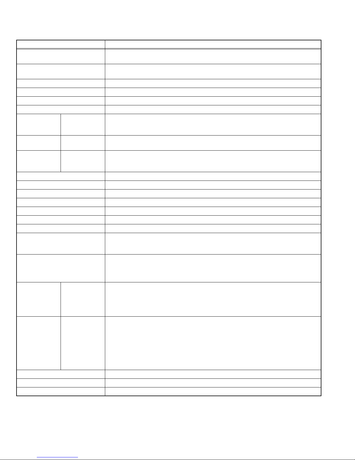
If the heat dissipation vent behind this unit is blocked, cooling efficiency may deteriorate and temperature inside the unit will rise.
Therefore, please make sure pay attention not to block the heat dissipation vent as well as the ventilation outlet behind the unit and
ensure that there is room for ventilation around it.
Distance recommendations
Avoid improper installation and never position the unit where good
ventilation is impossible.
150 mm
When installing this TV, distance recommendations must be maintained
between the set and the wall, as well as inside a tightly enclosed area or
piece of furniture.
Keep to the minimum distance guidelines shown for safe operation.
1.2.2 INSTALLATION REQUIREMENTS
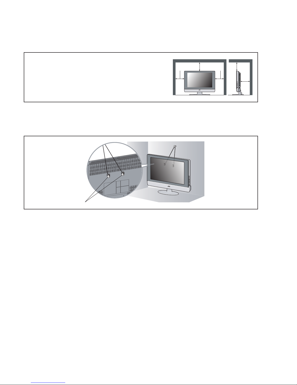
To ensure safety in an emergency such as an earthquake, and to prevent accidents, ensure that measures are taken to prevent the
TV dropping or falling over.
Use the supplied screws to firmly attach the supplied hooks to the back of the TV, and use commercially available cord to fix the TV
to rigid components such as walls and columns.
200 mm 200 mm
150 mm
50 mm
Supplied hooks
1.2.3 NOTES ON HANDLING
(1) WHEN TAKING UNIT OUT OF A PACKING CASE
When taking the unit out of a packing case, do not grasp the upper part of the unit. If you take the unit out while grasping the
upper part, the LCD PANEL may be damaged because of a pressure. Instead of grasping the upper part, put your hands on the
lower backside or sides of the unit.
(2) AS FOR PRESSING OR TOUCHING A SPEAKER
Be careful not to press the opening of the speaker in the lower part of the unit and around them since the decorative sheet on
the surface of the openings may be deformed.
1-4 (No.YA169)
Page 5

1.3 HANDLING LCD PANEL
1.3.1 PRECAUTIONS FOR TRANSPORTATION
When transporting the unit, pressure exerted on the internal LCD panel due to improper handling (such as tossing and dropping) may
cause damages even when the unit is carefully packed. To prevent accidents from occurring during transportation, pay careful
attention before delivery, such as through explaining the handling instructions to transporters.
Ensure that the following requirements are met during transportation, as the LCD panel of this unit is made of glass and therefore
fragile:
(1) USE A SPECIAL PACKING CASE FOR THE LCD PANEL
When transporting the LCD panel of the unit, use a special packing case (packing materials). A special packing case is used
when a LCD panel is supplied as a service spare part.
(2) ATTACH PROTECTION SHEET TO THE FRONT
Since the front (display part) of the panel is vulnerable, attach the protection sheet to the front of the LCD panel before
transportation. Protection sheet is used when a LCD panel is supplied as a service spare part.
(3) AVOID VIBRATIONS AND IMPACTS
The unit may be broken if it is toppled sideways even when properly packed. Continuous vibration may shift the gap of the panel,
and the unit may not be able to display images properly. Ensure that the unit is carried by at least 2 persons and pay careful
attention not to exert any vibration or impact on it.
(4) DO NOT PLACE EQUIPMENT HORIZONTALLY
Ensure that it is placed upright and not horizontally during transportation and storage as the LCD panel is very vulnerable to
lateral impacts and may break. During transportation, ensure that the unit is loaded along the traveling direction of the vehicle,
and avoid stacking them on one another. For storage, ensure that they are stacked in 2 layers or less even when placed upright.
1.3.2 OPTICAL FILTER (ON THE FRONT OF THE LCD PANEL)
(1) Avoid placing the unit under direct sunlight over a prolonged period of time. This may cause the optical filter to deteriorate in
quality and colour.
(2) Clean the filter surface by wiping it softly and lightly with a soft and lightly fuzz cloth (such as outing flannel).
(3) Do not use solvents such as benzene or thinner to wipe the filter surface. This may cause the filter to deteriorate in quality or the
coating on the surface to come off. When cleaning the filter, usually use the neutral detergent diluted with water. When cleaning
the dirty filter, use water-diluted ethanol.
(4) Since the filter surface is fragile, do not scratch or hit it with hard materials. Be careful enough not to touch the front surface,
especially when taking the unit out of the packing case or during transportation.
1.3.3 PRECAUTIONS FOR REPLACEMENT OF EXTERIOR PARTS
Take note of the following when replacing exterior parts (REAR COVER, FRONT PANEL, etc.):
(1) Do not exert pressure on the front of the LCD panel (filter surface). It may cause irregular colour.
(2) Pay careful attention not to scratch or stain the front of the LCD panel (filter surface) with hands.
(3) When replacing exterior parts, the front (LCD panel) should be placed facing downward. Place a mat, etc. underneath to avoid
causing scratches to the front (filter surface).
(No.YA169)1-5
Page 6

SECTION 2
SPECIFIC SERVICE INSTRUCTIONS
2.1 FEATURES
2.1.1 FUNCTION / CIRCUITS
• DIST (Digital Image Scaling Technology) employs an interpolation
method that doubles the scanning lines to realize 1250-line flickerfree picture making it especially suitable for reproducing highresolution pictures even on large-screen displays.
• New chassis design enable use of an interactive on screen
control.
• The TELETEXT SYSTEM has a built-in FASTEXT (UK
system), TOP (German system) and WST (world standard
system) system.
• Because this TV unit corresponds to multiplex broadcast,
users can enjoy music programs and sporting events with live
realism. In addition, BILINGUAL programs can be heard in
their original language.
• Users can make VCR dubbing of picture and sound by
controlling the AV selector to select an optional source at the
EXT-2 output shown in figure.
2.1.2 21-PIN EURO CONNECTOR (SCART) : EXT-1/EXT-2
Pin No. Signal designation Matching value EXT-1 EXT-2
1 AUDIO R output 500mV(rms) (Nominal), Low impedance Used (TV OUT) Used (LINE OUT)
2 AUDIO R input 500mV(rms) (Nominal), High impedance Used (R1) Used (R2)
3 AUDIO L output 500mV(rms) (Nominal), Low impedance Used (TV OUT) Used (LINE OUT)
4 AUDIO GND Used Used
5 GND (B) Used Used
6 AUDIO L input 500mV(rms) (Nominal), High impedance Used (L1) Used (L2)
7 B input 700mV
8 FUNCTION SW
(SLOW SW)
9 GND (G) Used Used
10 SCL / T-V LINK Not used Used
11 G input 700mV
12 SDA Not used Used (SDA2)
13 GND (R) Used Used
14 GND (YS) Used Not used
15 R / C input R : 700mV
16 Ys input (FAST SW) Low : 0V-0.4V, High : 1V-3V, 75Ω Used Used
17 GND (VIDEO output) Used Used
18 GND (VIDEO input) Used Used
19 VIDEO output 1V
20 VIDEO / Y input 1V
21 COMMON GND Used Used
(P-P= Peak to Peak, B-W= Blanking to white peak)
Low : 0V-3V
High : 8V-12V, High impedance
C : 300mV
(P-P)
(P-P)
, 75Ω Used Used
(B-W)
, 75Ω Used Used
(B-W)
, 75Ω
(B-W)
, 75Ω
(P-P)
(Negative sync), 75Ω Used (TV OUT) Used (LINE OUT)
(Negative sync), 75Ω Used Used
[Pin assignment]
20 18 16 14 12 10 8 6 4 2
TV EXT-1 EXT-3
EXT-2
Used Used
(SCL2 / TV-LINK)
Used (R) Used (C2/R)
EXT-4
1-6 (No.YA169)
21 19 17 15 13 11 9 7 5 3 1
Page 7

2.2 TECHNICAL INFORMATION
2.2.1 LCD PANEL
This unit uses the flat type panel LCD (Liquid Crystal Display) panel that occupies as little space as possible, instead of the
conventional CRT (Cathode Ray Tube), as a display unit.
2.2.1.1 STRUCTURE
The LCD panel of the unit is constructed with the metal chassis that surrounds the panel unit and supports the LCD panel part and
the backlight part to protect them.
The colour filter glass and the TFT glass (thin film transistor) are inserted between the front polarizing filter and the rear polarizing
filter. Liquid crystals are inserted between the colour filter glass and the TFT glass. Since the gap between the two glasses is only a
few µm, a spacer (bead) is inserted in the gap to retain the gap.
The backlight unit is placed behind the LCD panel. Since liquid crystals themselves do not emit light, the backlight as an external light
source emits light to the LCD panel from behind through the diffuser.
Circuit boards for controlling the LCD panel and the backlight are attached around the back part of the LCD panel unit.
Since the unit has the two polarizing filter that are at right angles to each other, the unit adopts "normally black" mode, where light
does not pass through the polarizing filter and the screen is black when no voltage is applied to the liquid crystals.
Diffuser supporter
Top chassis
Lower frame
Upper frame
Source board
Sield case
Inverter shield cover
Inverter board
Reflection plate
Panel ASSY
Diffuser (including board)
Lamp supporter
Fig.1 Structure of the LCD panel unit
2.2.1.2 SPECIFICATIONS
The following table shows the specifications of this unit.
Item Specifications Remarks
Maximum dimensions ( W × H × D ) 62.7cm × 38.9cm × 4.9cm
Weight 8.0kg
Effective screen size Diagonal : 66cm (H:33.9cm × V : 56.6cm) 26V type
Aspect ratio 15:9
Drive device/ system a-Si-TFT, active matrix system
Resolution Horizontally 1280 × Vertically 768 × RGB <W-XGA> 2949120 dots in total
Pixel pitch (pixel size) Horizontally:0.4425mm, Vertically:0.4425mm
Displayed colour 16777216 colours 256 colours for R, G, and B
Brightness 450cd/m
2
500cd/m2 at maximum
Contrast ratio 500:1
Response time 16.7ms
View angle Vertically 170°, horizontally 170°
2.2.1.3 PIXEL FAULT
There are three pixel faults - bright fault , dark fault and flicker fault - that are respectively defined as follows.
(1) BRIGHT FAULT
In this pixel fault, a cell that should not light originally is lighting on and off.
For checking this pixel fault, input ALL BLACK SCREEN and find out the cell that is lighting on and off.
(2) DARK FAULT
In this pixel fault, a cell that should light originally is not lighting or lighting with the brightness twice as brighter as originally lighting.
For checking this pixel fault, input 100% of each R/G/B colour and find out the cell that is not lighting.
(3) FLICKER FAULT
In the pixel fault, a cell that should light originally or not light originally is flashing on and off.
For checking this pixel fault, input ALL BLACK SCREEN signal or 100% of each RGB colour and find out the cell that is flashing on
and off.
(No.YA169)1-7
Page 8

2.2.2 MAIN CPU PIN FUNCTION (IC001)
Pin No. Pin Name I/O Remark
1 TCK I Test purpose
2 TMS I Test purpose
3 TDI I Test purpose
4 TDO O Test purpose
5 P2.8 I Remote control input
6 P2. 9 I Mechanical power switch detection [Pushing:L]
7 P2.10 I IP error detection [Detection:L]
8 P2.11 O IP reset
9 P2.12 I TV-LINK communication
10 P2.13 I Power ON/OFF [ON:L]
11 P2.14 I Low B protect detection [Detection:L]
12 P2.15 I Power condition check [ON:L]
13 VSS33 I GND
14 VDD33 I 3.3V
15 P4.5 O TV-LINK communication
16 A20 O Memory (Program ROM) address
17 A19 O Memory (Program ROM) address
18 A18 O Memory (Program ROM) address
19 A17 O Memory (Program ROM) address
20 VSS25 I GND
21 VDD25 I 2.5V
22 A16 O Memory (Program ROM) address
23 A8 O Memory (Program ROM) address
24 A7 O Memory (Program ROM) address
25 A9 O Memory (Program ROM) address
26 A6 O Memory (Program ROM) address
27 A5 O Memory (Program ROM) address
28 A10 O Memory (Program ROM) address
29 A11 O Memory (Program ROM) address
30 A12 O Memory (Program ROM) address
31 VSS33 I GND
32 VDD33 I 3.3V
33 A4 O Memory (Program ROM) address
34 A3 O Memory (Program ROM) address
35 A2 O Memory (Program ROM) address
36 A1 O Memory (Program ROM) address
37 A0 O Memory (Program ROM) address
38 A13 O Memory (Program ROM) address
39 RAS/A14 O Memory (Program ROM) address
40 CAS/A15 O Memory (Program ROM) address
41 VSS33 I GND
42 VDD33 I 3.3V
43 MEMCLK O Clock for memory
44 CSSDRAM O Chip select for memory
45 CLKEN O Clock enable for memory
46 CSROM O Chip select for memory
47 RD O Read for memory
48 UDQM O Control IN/OUT buffer of Memory (IC003)
49 LDQM O Control IN/OUT buffer of Memory (IC003)
50 WR O Write for memory
51 D15 I/O Data (Program ROM)
52 VSS33 I GND
53 VDD33 I 3.3V
54 D7 I/O Data (Program ROM)
55 D0 I/O Data (Program ROM)
56 D14 I/O Data (Program ROM)
57 D8 I/O Data (Program ROM)
58 D6 I/O Data (Program ROM)
59 D1 I/O Data (Program ROM)
60 VSS33 I GND
61 VDD33 I 3.3V
62 D13 I/O Data (Program ROM)
63 D9 I/O Data (Program ROM)
64 D5 I/O Data (Program ROM)
Pin No. Pin Name I/O Remark
65 D2 I/O Data (Program ROM)
66 D12 I/O Data (Program ROM)
67 D10 I/O Data (Program ROM)
68 VSS33 I GND
69 VDD33 I 3.3V
70 D4 I/O Data (Program ROM)
71 D3 I/O Data (Program ROM)
72 D11 I/O Data (Program ROM)
73 RSTIN I Reset
74 P3.0 O I
75 P3.1 I/O I
2
C CLOCK 0 (for memory)
2
C DATA 0 (for memory)
76 P3.2 I Remote control input
77 P3.3 I Clock for OSD
78 P3.4 O Tuner system switch
79 P3.5 O Tuner system switch
80 P3.6 I Teletext mode:H
81 P3.7 I Power START
82 P3.8 I Not used
83 P3.9 I Picture mute
84 VSS33 I GND
85 VDD33 I 3.3V
86 VSS25 I GND
87 VDD25 I 2.5V
88 TXD0 O Sub micro computer communication
89 RXD0 I Sub micro computer communication
90 P3.12 I Not used
91 P3.13 I/O Not used
92 P3.15 I/O Not used
93 P5.14(YS2) I Ys for EXT-2
94 P5.15 I Headphone detection [Detection:L]
95 TRIG_IN I/O Not used
96 TRIG_OUT I/O Not used
97 P6.2 I Not used
98 P6.3 O I
99 P6.4 I/O I
2
C bus clock for IC control
2
C bus data for IC control
100 P6.5 O Multi-sound process reset
101 P6.6 I/O I
2
C bus data for IC control
102 VSYNC O Vertical sync for OSD
103 HSYNC O Horizontal sync for OSD
104 COR/RSTOUT O Not used
105 BLANK O Ys for OSD/Teletext
106 VDD33 I 3.3V
107 VSS33 I GND
108 XTAL1 I 6MHz
109 XTAL2 O 6MHz
110 VSSA I GND
111 VDDA I Not used
112 R O R for OSD Teletext
113 G O G for OSD Teletext
114 B I B for OSD Teletext
115 VSSA I GND
116 VDDA I 2.5V
117 CVBS2 I Video for Teletext
118 VSSA I GND
119 VDDA I 2.5V
120 CVBS1B I Video for Teletext
121 CVBS1A I Video for Teletext
122 VSSA I GND
123 VDDA I 2.5V
124 P5.0 I AFT for tuner
125 P5.1(KEY1) I Key scan data 1 [ON:H]
126 P5.2 I AGC for tuner
127 P5.3(KEY2) I Key scan data 2 [ON:H]
128 TMODE I Test purpose
1-8 (No.YA169)
Page 9

2.2.3 SUB CPU PIN FUNCTION (IC7807)
Pin No. Pin name I/O Function
1 (SYSTEM0) I GND
2 (SYSTEM3) I GND
3AVCC -5V
4 X2 - Sub clock
5 X1 - Sub clock
6 VCL - Internal down voltage
7 RES I Reset [Reset : L]
8 TEST I Operation test for SUB CPU
9VSS -GND
10 OSC2 O 10MHz oscillation for system clock
11 OSC1 I 10MHz oscillation for system clock
12 VCC - 5V
13 NC O Not used
14 NC O Not used
15 BL_D2 O Back light 20ms delay for LCD panel [On:L]
16 BL_D1 O Back light 10ms delay for LCD panel [On:L]
17 I2C_STOP O Not used
18 BL_ON O Back light reset for LCD panel [Reset:L]
19 NC O Not used
20 NC O Not used
21 NC O Not used
22 NC O Not used
23 SDA1 I/O
24 A.DIM O Not used
25 SCL1 O
26 SDA0 I/O
27 SCL0 O
28 NC O Not used
29 NC O Not used
30 NC O Not used
31 NC O Not used
32 NC O Not used
33 NC O Not used
34 NC O Not used
35 NMI I Port for writing on board [Writning:L]
36 NC O Not used
37 (HD) I Not used
38 NC O Not used
39 (REMO) I Not used
40 NC O Not used
41 P85 -/I Not used
42 P86 - Not used
43 P87 - Not used
44 SCK3 O Port for writing on board
45 RXD I Port for writing on board
46 TXD O Port for writing on board
47 (PROTECTOR0) I Not used
48 NC O Not used
49 RXD2 I Port for communication (Main CPU)
50 TXD2 O Port for communication (Main CPU)
51 NC O Not used
52 (ACTIVE) I Not used
53 VD I Vertical sync
54 (REC_DET) I Not used
55 (PSS) I Not used
56 (ALARM) I Not used
57 (SYSTEM2) I Not used
58 (SYSTEM1) I Not used
59 (PROTECTOR1) I Not used
60 (AMP_PRO2) I Not used
61 (AMP_PRO1) I Not used
62 EE_CDS I Not used
63 (KEY_IN1) I Not used
64 (KEY_IN2) I Not used
2
C bus data (For Sub memory)
I
2
C bus clock (For Sub memory)
I
2
C bus data (For general)
I
2
C bus clock (For general)
I
(No.YA169)1-9
Page 10
SECTION 3
DISASSEMBLY
3.1 DISASSEMBLY PROCEDURE
CAUTION:
Since this model is a laminating structure assembly, please
perform in following order in the case of disassembling.
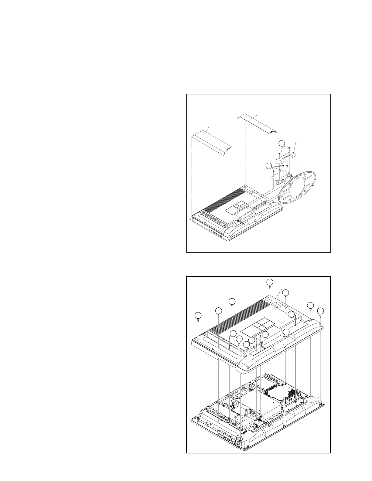
3.1.1 REMOVING THE STAND ASS'Y (Fig.3-1-1)
(1) Remove the 2 screws [A], and remove the COVER.
(2) Remove the 4 screws [B], and remove the STAND ASS'Y.
JACK COVER(L)
JACK COVER(R)
STAND COVER
A
3.1.2 REMOVING THE REAR COVER (Fig.3-1-1, Fig.3-1-2)
• Remove the STAND ASS'Y.
(1) Remove the JACK COVER(R) and JACK COVER(L).
(2) Remove the 7 screws [C], 3 screws [D], 4 screws [E], and
remove the REAR COVER.
B
STAND
Fig.3-1-1
C
REAR COVER
E
E
C
E
D
C
C
D
D
E
C
C
C
1-10 (No.YA169)
Fig.3-1-2
Page 11
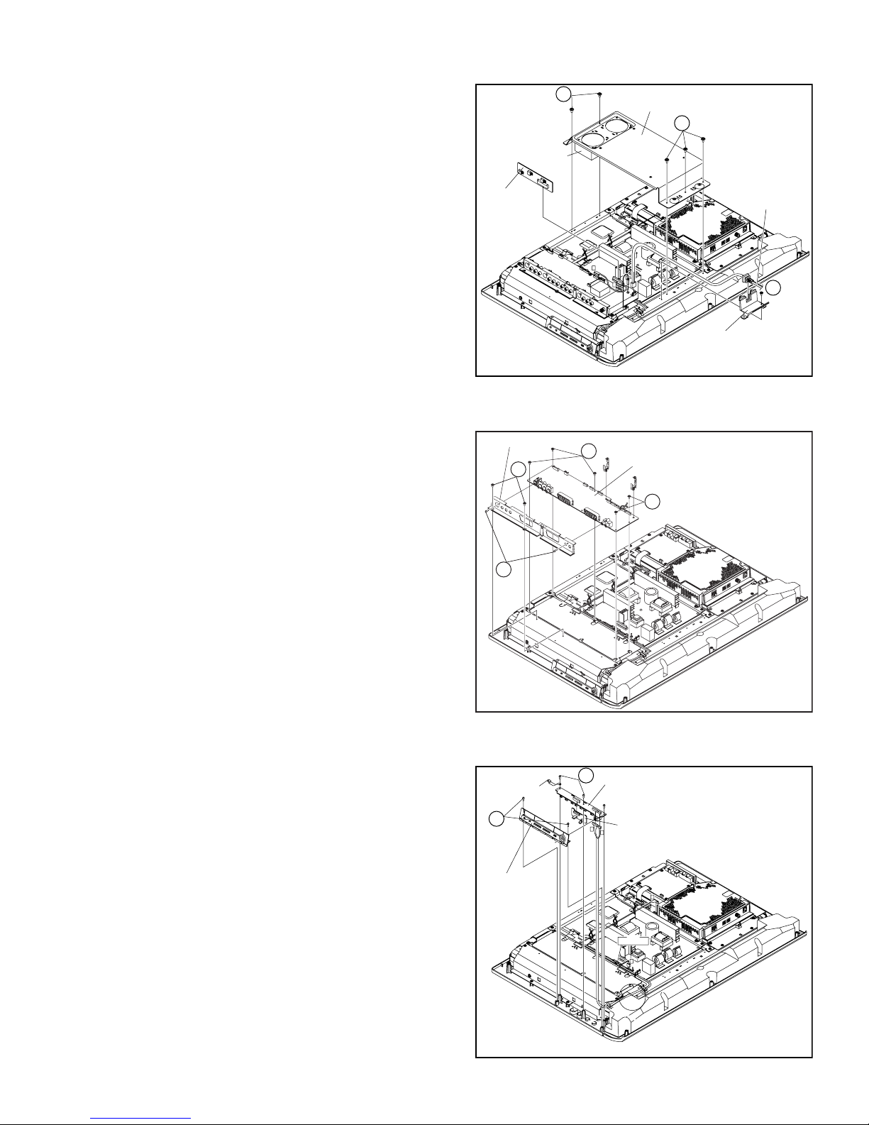
3.1.3 REMOVING THE FAN BRACKET, REGULATOR PWB AND POWER CORD (Fig.3-1-3)
• Remove the STAND ASS'Y.
• Remove the REAR COVER.
F
(1) Disconnect the wire(CONN. [Y]) of COOLING FAN.
(2) Remove the 5 screws [F], and remove the FAN BRACKET.
(3) Remove the REGULATOR PWB, and disconnect the
POWER CORD.
COOLING FAN
(4) Remove the 1 screw [G], and remove the POWER CORD
HOLDER.
REGULATOR
PWB
G
3.1.4 REMOVING THE RECEIVER PWB (Fig.3-1-4)
• Remove the STAND ASS'Y.
• Remove the REAR COVER.
(1) Remove the 2 screws [H] and 2 screws [J], then remove the
TERMINAL BASE.
TERMINAL BASE
H
K
(2) Remove the 5 screws [K], and remove the RECEIVER
PWB.
FAN BRACKET
G
Fig.3-1-3
RECEIVER PWB
K
F
POWER CORD
G
POWER CORD HOLDER
J
3.1.5 REMOVING THE FRONT CONTROL PWB AND FRONT SENSOR PWB (Fig.3-1-5)
• Remove the STAND ASS'Y.
• Remove the REAR COVER.
(1) Remove the 2 screws [L], and remove the CONTROL
KNOB.
(2) Remove the 3 screws [N], then remove the FRONT
EARTH PLATE
L
M
CONTROL PWB and FRONT SENSOR PWB.
CONTROL KNOB
Fig.3-1-4
FRONT CONTROL PWB
FRONT SENSOR PWB
T
U
T
CLAMP
HARNES( F,U,T),"S" WIRE
F
Fig.3-1-5
(No.YA169)1-11
Page 12
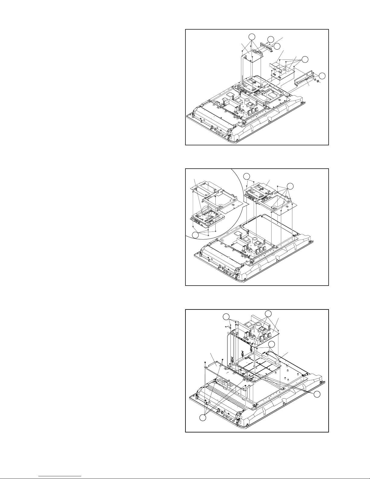
3.1.6 REMOVING THE VIDEO PWB (Fig.3-1-6)
• Remove the STAND ASS'Y.
• Remove the REAR COVER.
(1) Remove the 2 screws [N] and 1 screws [P], then remove
the JACK BASE.
(2) Remove the 4 screws [Q], and remove the VIDEO PWB.
(3) Remove the 2 screws [R], and remove the TUNER PWB
BASE.
(4) Remove the 4 screws [S], and remove the TUNER PWB
and MSP PWB.
3.1.7 REMOVING THE MI-COM & DIST PWB (Fig.3-1-7)
• Remove the STAND ASS'Y.
• Remove the REAR COVER.
(1) Remove the 7 screws [T], and remove the VIDEO PWB
BRACKET.
(2) Remove the 4 screws [U], and remove the MI-COM & DIST
PWB from VIDEO PWB BRACKET.
VIDEO PWB
MI-COM&DIST PWB
X
Q
JACK BASE
N
P
Fig.3-1-6
VIDEO PWB BRACKET
T
TUNER PWB
MSP PWB
S
R
TUNER PWB
BASE
T
3.1.8 REMOVING THE POWER PWB (Fig.3-1-8)
• Remove the STAND ASS'Y.
• Remove the REAR COVER.
• Remove the FUN BRACKET.
• Remove the POWER CORD.
• Remove the VIDEO PWB.
(1) Remove the 4 screws [X], and remove the AV JACK
BRACKET.
(2) Remove the 6 screws [Y], and remove the POWER PWB.
(3) Remove the 6 screws [Z], and remove the POWER PWB
BASE.
U
AV JACK
BRACKET
Fig.3-1-7
Y
Y
Q
P
POWER PWB
Z
POWER PWB
BASE
Z
1-12 (No.YA169)
X
Fig.3-1-8
Page 13

3.1.9 REMOVING THE SPEAKER (Fig.3-1-9A, Fig.3-1-9B)
• Remove the STAND ASS'Y.
• Remove the REAR COVER.
• Remove the POWER CORD.
(1) Remove the 5 screws [a], and remove the SPEAKER BOX.
a
SPEAKER BOX
a
Fig.3-1-9A
(2) Remove the 4 screws [b], and remove the SPEAKER (L/R).
(3) Remove the 4 screws [c], and remove the DUCT COVER/
DUCT BASE.
NOTE:
Since the speaker is attached in a certain direction, attach the
speaker in the same correct direction as it has been attached.
DUCT BASE/DUCT COVER
c
b
SPEAKER
㧔R㧕
Fig.3-1-9B
c
b
SPEAKER
㧔L㧕
(No.YA169)1-13
Page 14
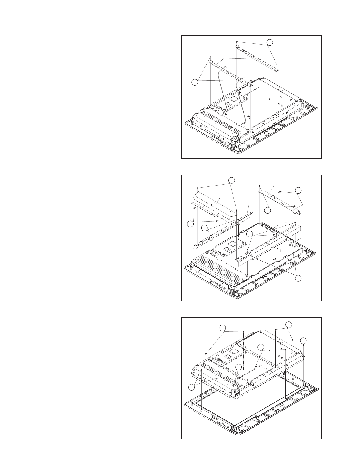
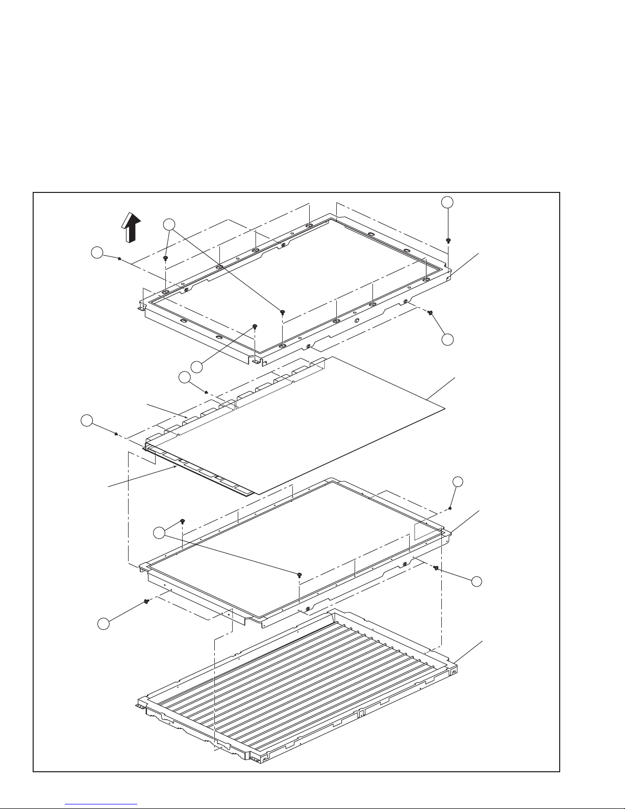
3.1.10 REMOVING THE LCD PANEL (Fig.3-1-10C, Fig.3-1-10A, Fig.3-1-10B)
• Remove the STAND ASS'Y.
• Remove the REAR COVER.
• Remove the POWER CORD.
• Remove the RECEIVER PWB.
• Remove the FRONT CONTROL PWB.
• Remove the FRONT SENSOR PWB.
• Remove the VIDEO PWB.
• Remove the MI-COM & DIST PWB
a
• Remove the POWER PWB.
(1) Remove the 2 screws [a], and remove the 2 CENTRE
FRAMES.
a
CENTRE
FRAME
X
P
Q
Fig.3-1-10A
(2) Remove the 2 screws [b] and 2 screws [c], then remove the
RIGHT FRAME.
(3) Remove the 2 screws [b] and 2 screws [c], then remove the
LEFT FRAME.
(4) Remove the 2 screws [d], and remove the TOP FRAME.
(5) Remove the 3 screws [e] and 2 screws [f], then remove the
BOTTOM FRAME.
(6) Remove the 8 screws [g] and 2 screws [h], then remove the
LCD PANEL.
NOTE:
The LCD PANEL is fixed to the FRONT PANEL (at the
back side) by using double-side adhesive tapes. To
remove the LCD PANEL, remove the adhesive tape on
the FRONT PANEL slowly.
b
RIGHT
FRAME
c
d
TOP
FRAME
e
LEFT FRAME
c
b
BOTTOM
FRAME
f
Fig.3-1-10B
g
g
h
g
h
1-14 (No.YA169)
g
Fig.3-1-10C
Page 15
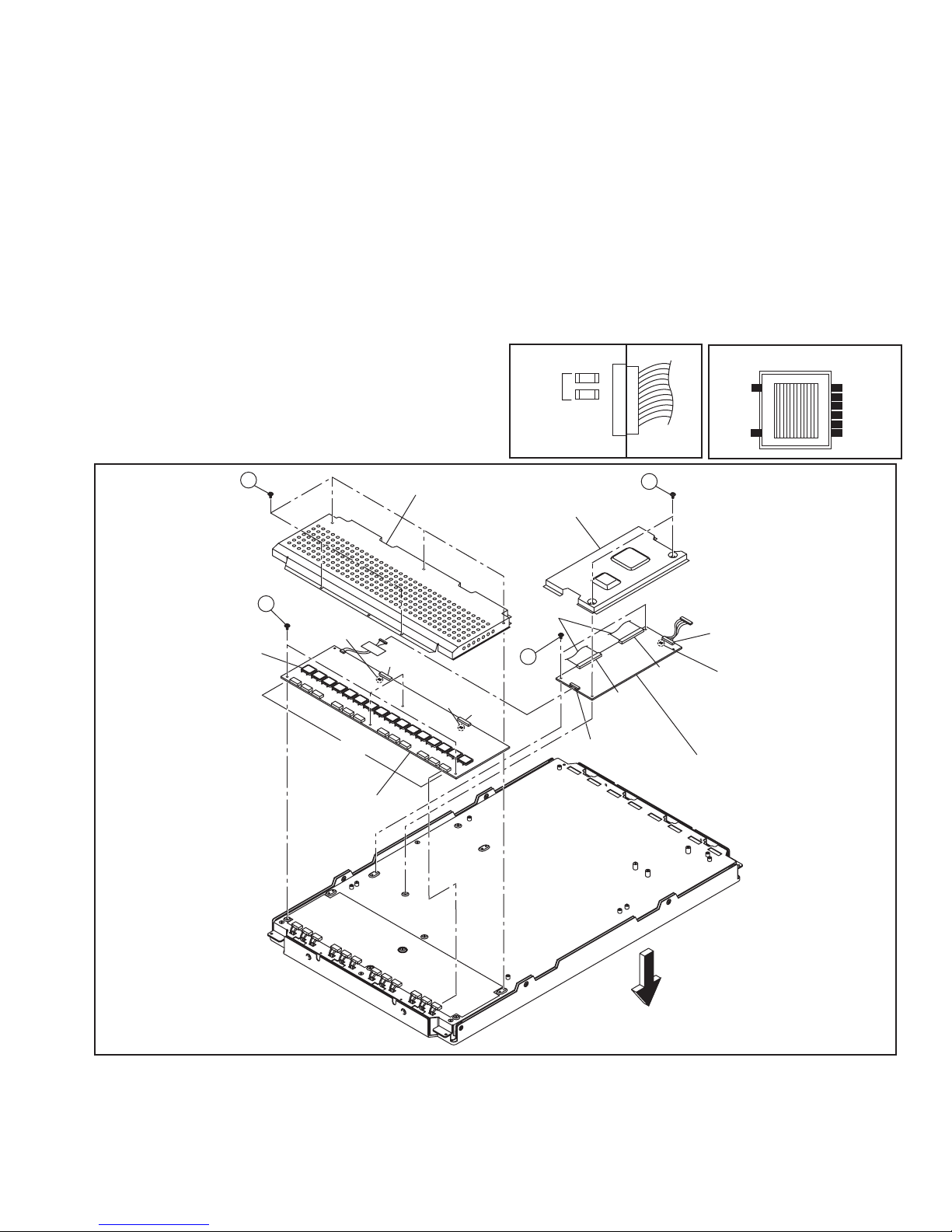
3.1.11 REMOVING THE LCD PANEL
3.1.11.1 REMOVING THE CONTROL PWB
• Place the LCD PANEL with its backside facing upward.
Be careful not to damage the surface of the screen.
(1) Remove the 2 screws [A], and remove the CONTROL
PWB COVER.
(2) Remove the claws in the connectors [FPC RIGHT] and
[FPC LEFT], and pull out to remove the FLEXIBLE PWB.
NOTE:
Be careful not to damage the FLEXIBLE PWB.
Especially during assembly procedure, be careful not to
insert the FLEXIBLE PWB in the Panel.
(3) Remove the 2 screws [B], and remove the CONTROL
PWB.
[Confirmation after replacement]
• Confirm that voltage of 10 pin (B/L On/Off) in the connector
[CNI1] is approx.5.0V.
• Confirm that the voltage in output of the fuses [F1] and [F2]
in the connector [CNI1] is approx.5.0V.
3.1.11.2 REMOVING THE INVERTER PWB
(1) Remove the 5 screws [C], and remove the INVERTER
PWB COVER.
(2) Pull out and remove the wires from connectors [CN4]-
[CN15] (12 connectors in total).
(3) Remove the 4 screws [D], and remove the INVERTER
PWB.
[Confirmation after replacement]
• Confirm that the voltage in output of the fuses [F1] and [F2]
in the connector [CN1] and the fuses [F3] and [F4] in the
connector [CN2] is 16V.
• Confirm that the voltage in input of the TRANSFORMER in
the Inverter Board is 8V.
• Be careful about high voltage (approx. AC900V) in output.
FUSE
OUTPUT
CONTOROL PWB
INVERTER PWB
CONNECTOR
OUTPUT
TRANSFORMER
GND
8V
8V
8V
8V
GND
INPUT
C
TRANSFORMER
D
FUSE
(F3, F4)
[CN4㨪CN15]
INVERTER PWB
INVERTER PWB COVER
CONTROL PWB COVER
FLEXIBLE
CN2
FUSE
(
)
F1, F2
CN1
PWB
B
CNI1
A
FRC
RIGHT
CONTROL PWB
FRC
LEFT
CNT1
FUSE
(F1, F2)
FRONT
(No.YA169)1-15
Page 16
3.1.11.3 REMOVING THE BACKLIGHT UNIT
NOTE:
Do not carry out the following procedure in a dusty and dirty
place.
If the surface of LCD GLASS, the surface of DIFFUSER
SHEET, and the inside of BACKLIGHT UNIT are dusty or dirty,
they cause unevenness of a displayed screen.
• Remove the CONTROL PWB.
• Remove the INVERTER PWB.
• Place the LCD UNIT with the screen facing upward.
(1) Remove the 8 screws [E], 4screws [F], and 4 screws [G]
(16 screws in total), and remove the MAIN CHASSIS.
NOTE:
Be careful not to damage the SOURCE IC and the GATE
IC on the side of LCD GLASS when removing the MAIN
CHASSIS.
(2) Remove the 6 screws [H] from the top side of the LCD
UNIT.
(3) Remove the 12 screws [I] from the sides of the LCD UNIT.
Then, LCD GLASS, DIFFUSER SHEET, and BACKLIGHT
UNIT are removed.
G
SOURCE IC
I
GATE IC
FRONT
F
E
MAIN CHASSIS
G
F
I
LCD GLASS
I
DIFFUSER SHEET
H
I
1-16 (No.YA169)
I
BACKLIGHT UNIT
Page 17
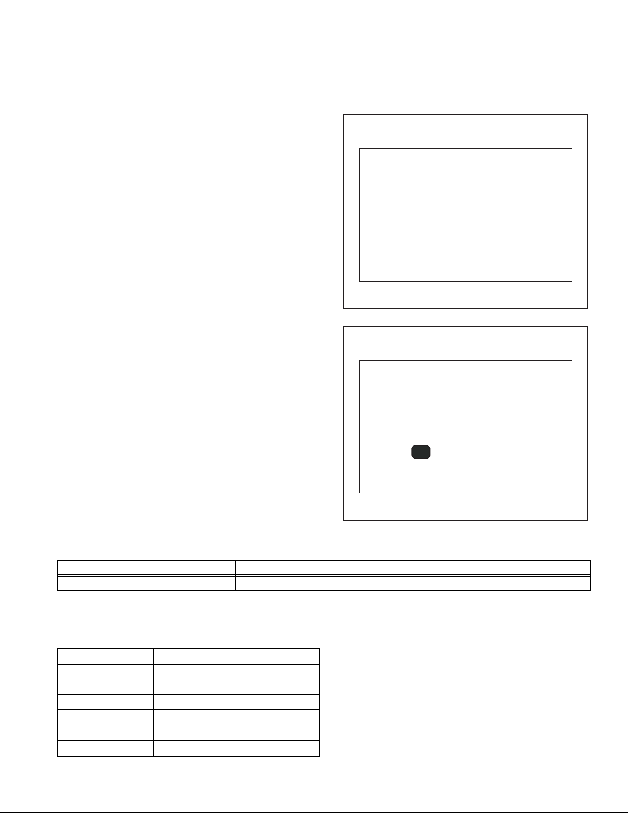
3.2 REPLACEMENT OF MEMORY IC
SERVICE MENU SCREEN
SYSTEM CONSTANT SET SCREEN
This unit uses the nonvolatile memory IC.The memory IC memories data for video and deflection circuits. To replace the memory IC
without the data written, malfunctions might occurred while power is on, and the normal image might not appear. When replacing the
memory IC, be sure to use the IC written with the initial values of data.
3.2.1 PROCEDURE FOR REPLACING THE MEMORY IC
(1) Switch the power off and unplug the power cord from the
wall outlet.
(2) Replacing the memory IC. [Be sure to use the IC written
with the initial values of data]
(3) Plug the power cord into the wall outlet and switch the
power on.
(4) Check and setting of SYSTEM CONSTANT SET
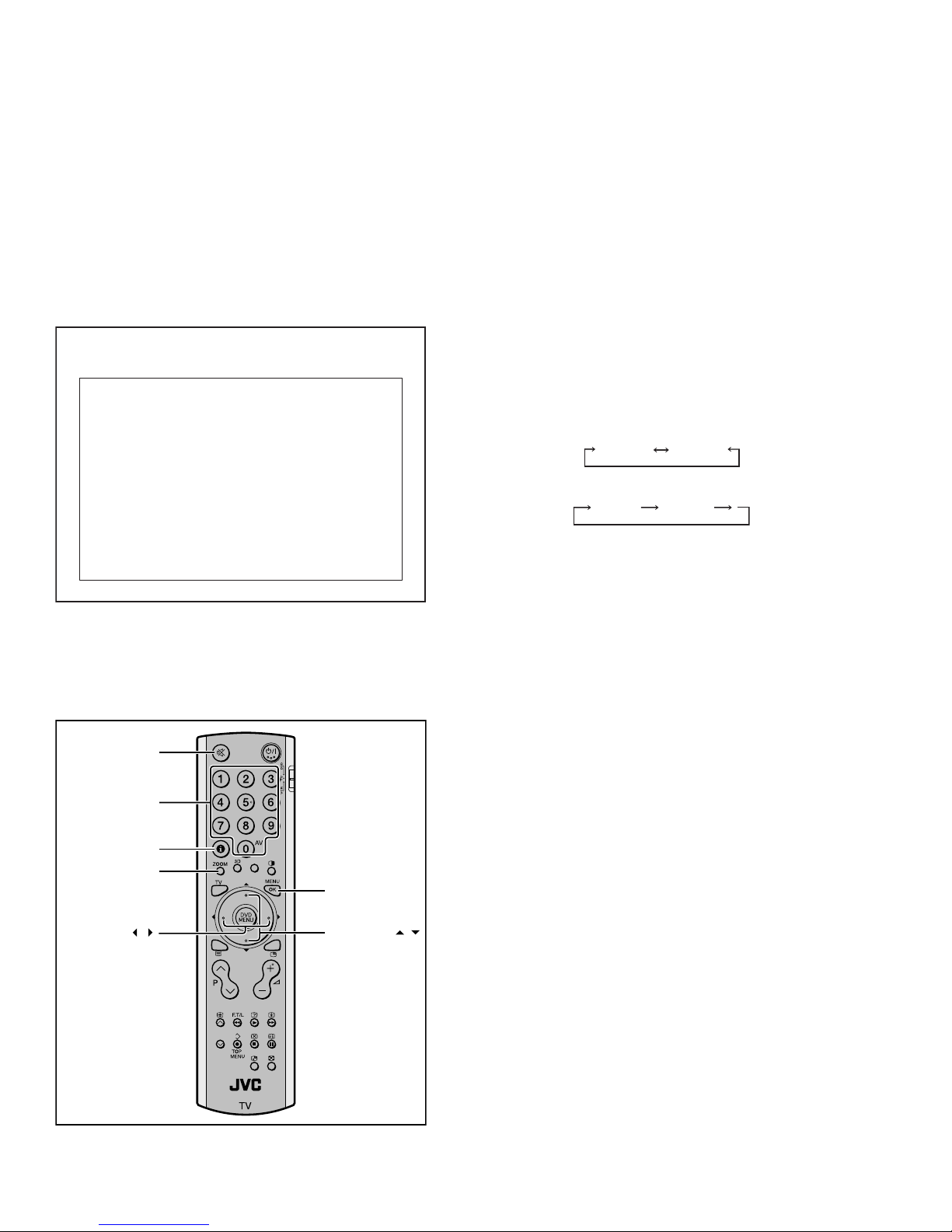
a) Press the [INFORMATION] key and [MUTING] key
on the remote control unit simultaneously.
The SERVICE MENU screen will be displayed. (See
Fig.1)
b) In the SERVICE MENU, press the [INFORMATION]
key and [MUTING] key simultaneously.
Then, the SYSTEM CONSTANT SET screen will be
displayed. (See FIg.2)
c) Check whether the setting value of the SYSTEM
CONSTANT SET is the same as these indicated in
Table 1.
d) Press the [INFORMATION] key twice to return to the
normal screen.
(5) Receive channel setting
Refer to the OPERATING INSTRUCTIONS and set the
receive channels.
(6) User setting
Memories the user setting items.The [USER SETTINGS
OF MENU] setting is as next page.
(7) Setting of SERVICE MENU
Check the setting items in the SERVICE MENU, set if
necessary.For setting method, please refer to the
[ADJUSTMENT PREPARATION] to [ADJUSTMENT
PROCEDURE] of ADJUSTMENT section.
SERVICE MENU SCREEN
SERVICE MENU
1. IF 2. V/C
3. AUDIO 4. DD/CM
5. VSM PRESET 6. STATUS
7. VNR 8. IP
9. SHIPPING (OFF) 0. BUS FREE
1-9 : SELECT i : EXIT
Fig.1
SYSTEM CONSTANT SET SCREEN
SYSTEM CONSTANT SET
1. DESTINATION EURO
-/+ : STORE i : EXIT
OK
3.2.2 SETTING OF THE SYSTEM CONSTANT SET
Setting item Setting content Setting value
DESTINATION ASIA / EURO EURO
3.2.3 FACTORY SHIPMENT SETTING
3.2.3.1 USER SETTING OF SWITCHS ON REMOTE CONTROL UNIT
Setting item Setting value
POWER OFF
CHANNEL PR1
PRESET CHANNEL Refer to OPERATION INSTRUCTIONS
VOLUME 10
ZOOM PANORAMIC
3D SOUND OFF
Table 2
Fig.2
Table 1
(No.YA169)1-17
Page 18

3.2.3.2 USER SETTINGS OF MENU
Setting item Setting value Setting item Setting value
POWER OFF SOUND SETTING
CHANNEL PR1 BASS Centre
TREBLE Centre
PRESET CHANNEL Refer to
OPERATING INSTRUCTIONS
BALANCE Centre
SPEAKER ON
VOLUME 10 BBE ON
PICTURE SETTING 3D SOUND OFF
PICTURE MODE BRIGHT A. H. B ON
COLOUR TEMP. COOL HEADPHONE VOLUME 20
TV SPEAKER OFF
OUTPUT MAIN
PICTURE FEATURES EXT SETTING
DIGITAL VNR AUTO S-IN ---
Super DigiPure AUTO ID LIST ---
COLOUR SYSTEM TV Depends on PR/CH DUBBING EXT-1 → EXT-2
EXT AUTO FEATURES
MOVIE THEATRE AUTO SLEEP TIMER OFF
4:3 AUTO ASPECT PANORAMIC BLUE BACK ON
COLOUR MANAGEMENT ON
CHILD LOCK / CHANNEL GUARD
SET ID NO 0000
PIP POSISION Right below INSTALL
ZOOM PANORAMIC LANGUAGE ENGLISH
AUTO PROGRAM Only for preset channels
EDIT/MANUAL Only for preset channels
Table 3
3.2.3.3 VSM PRESET SETTING
Setting value
Item No.
Setting
Item
Variable
range
PICTURE MODE COLOUR TEMP.
BRIGHT STD SOFT COOL NORMAL WARM
1 CONT -16~16 6 0 0 - - -
2 BRIGHT -16~16 -6 0 0 - - -
3 SHARP -16~16 3 0 -2 - - -
4 COLOUR -16~16 0 0 0 - - -
5 TINT -16~16 0 0 0 - - -
6 B. LIGHT -16~16 16 16 -8 - - -
1 WDR R -64~63 - - - -8 0 0
2 WDR G -64~63 - - - -3 0 -6
3 WDR B -64~63 - - - 23 0 -3
3.2.3.3.1 SETTING OF VSM PRESET
(1) Enter "5.VSM PRESET" from the SERVICE MENU.
(2) Press the [OK] key to select BRIGHT/STD/SOFT/COOL/NORMAL/WARM mode.
(3) Select the setting item using the [FUNCTION (UP/DOWN)] key.
(4) Set the value using the [FUNCTION (+/-)] key.
(5) Press the [OK] key to memorize the set value.
(6) Press the [INFORMATION] key twice to return to the normal screen.
1-18 (No.YA169)
Table 4
Page 19

3.2.3.4 SERVICE MENU SETTING ITEMS
Setting item Setting value Setting item Setting value
1.IF 1.VCO
6.STATUS (Do not adjust)
2.ATT ON/OFF
2.V/C 1.CUT OF R
2.CUT OF G
3.CUT OF B
4.DRIVE R
5.DRIVE G
6.DRIVE B
7.TWN HI R
8.TWN HI B
9.BRIGHT
10.CONT
11.TWN BRG
12.TWN CNT
13.COLOUR
14.HUE
15.BY GAIN
16.TWN COL
17.TWN TNT
7.VNR
(Do not adjust)
1.MYLV
2.ONMVF
3.MYCOR
4.MYGA
5.YEGON
6.YEGL
7.YLTL
8.MCLV
9.MCGA
10.MCCOR
11.CLTL
12.YNGA
13.COR_OF
14.LPF_OF
15.YCTL
16.YNCL
17.YNCON
18.B OF MR
19.B OF MB
20.B OF SR
21.B OF SB
22.M BOFST
23.M ROFST
S01 ~ S99
A01 ~ A17
PDA01 ~ PDA12
3.AUDIO
(Do not adjust)
4.DD/CM DDT01 ~ DDT34
5.VSM PRESET PICTURE MODE
1.ERROR LIMIT
2.A2 ID THR
3.Q-PEAK
4.SOUND LEVEL / SOUND SYSTEM B/G
CMT01 ~ CMT57
1.CONT
2.BRIGHT
8.IP
(Do not adjust)
PPA001 ~ PPA008
PPB001 ~ PPB036
PPC001 ~ PPC007
ADS001 ~ ADS034
IPA001 ~ IPA120
IPB001 ~ IPB088
IPC001 ~ IPC044
IPD001 ~ IPD058
9.SHIPPING(OFF) (Do not use under the adjustment)
3.SHARP
4.COLOUR
5.TINT
6.B. LIGHT
COLOUR TEMP.
1.WDR R
2.WDR G
3.WDR B
Table 5
(No.YA169)1-19
Page 20

3.3 REPLACEMENT OF CHIP COMPONENT
3.3.1 CAUTIONS
(1) Avoid heating for more than 3 seconds.
(2) Do not rub the electrodes and the resist parts of the pattern.
(3) When removing a chip part, melt the solder adequately.
(4) Do not reuse a chip part after removing it.
3.3.2 SOLDERING IRON
(1) Use a high insulation soldering iron with a thin pointed end of it.
(2) A 30w soldering iron is recommended for easily removing parts.
3.3.3 REPLACEMENT STEPS
1. How to remove Chip parts
[Resistors, capacitors, etc.]
(1) As shown in the figure, push the part with tweezers and
alternately melt the solder at each end.
(2) Shift with the tweezers and remove the chip part.
2. How to install Chip parts
[Resistors, capacitors, etc.]
(1) Apply solder to the pattern as indicated in the figure.
(2) Grasp the chip part with tweezers and place it on the
solder. Then heat and melt the solder at both ends of the
chip part.
[Transistors, diodes, variable resistors, etc.]
(1) Apply extra solder to each lead.
SOLDER
SOLDER
(2) As shown in the figure, push the part with tweezers and
alternately melt the solder at each lead. Shift and remove
the chip part.
NOTE :
After removing the part, remove remaining solder from the
pattern.
[Transistors, diodes, variable resistors, etc.]
(1) Apply solder to the pattern as indicated in the figure.
(2) Grasp the chip part with tweezers and place it on the
solder.
(3) First solder lead A as indicated in the figure.
A
B
C
(4) Then solder leads B and C.
A
B
C
1-20 (No.YA169)
Page 21

SECTION 4
ADJUSTMENT
4.1 ADJUSTMENT PREPARATION
(1) Prior to the following procedure, be sure to connect the
receiver unit and the display unit.
(2) Adjustment of many Majority of the adjustment items for
this unit is performed using the remote control.
(3) However, adjustment of some adjustment items is
performed in the conventional way, i.e. with components
on the boards.
(4) Ensure that the power supply is AC220V.
(5) Allow the set and the measuring devices to run for at least
30 minutes.
(6) Do not alter settings of items/preset values on the service
screen that are not stated in this manual.
(7) Unless otherwise stated in the “ADJUSTMENT
PROCEDURE” section, follow the settings for the features
stated below using the remote control.
Setting item Settings
PICTURE MODE STANDARD
PICTURE adjustment All center (00)
COLOUR TEMP. NORMAL
DIGITAL VNR MIN
Super Digi Pure AUTO
SOUND adjustment All center (00)
BBE OFF
AHS OFF
A.H.B OFF
ZOOM FULL
4.2 MEASURING INSTRUMENT AND FIXTURES
• DC voltmeter (or Digital voltmeter)
• Oscilloscope
• Signal generator (Pattern generator)
• Remote control unit
(No.YA169)1-21
Page 22
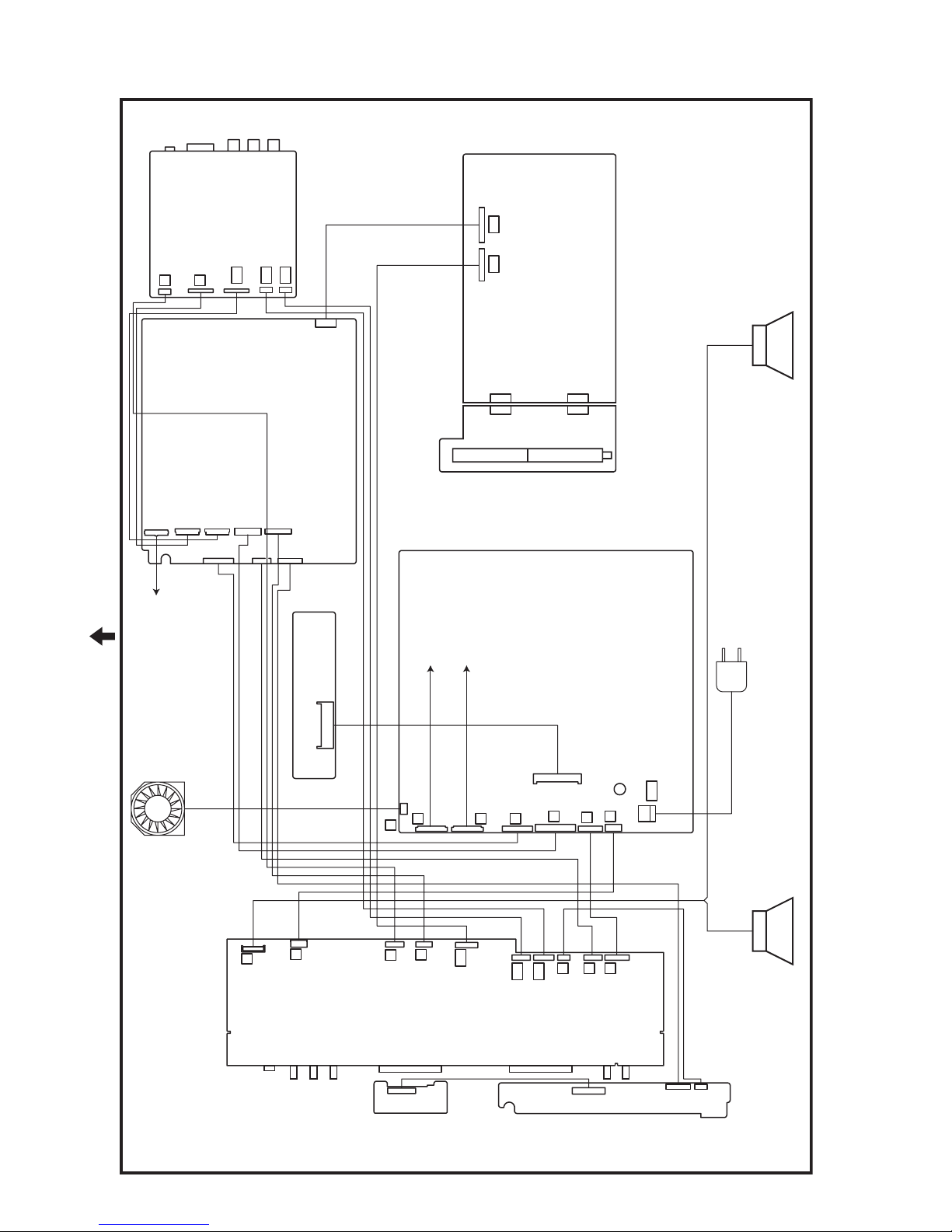
4.3 ADJUSTMENT LOCATION & WIRING
VIDEO PWB
AE
AD
AH
H
N
CN00AM
MI-COM & DIST PWB
AL AM
CN004
CN004 CN005
MSP PWB
CN005
TUNER PWB
CN000A
CN000H
CN000X
CN00AH
CN000B
TOP
CONTOROL PWB
(LCD UNIT : CNT1)
CN000J
CN000K
CN000T
PWB
REGULATOR
INVERTER PWB
(LCD UNIT : CN2)
INVERTER PWB
(LCD UNIT : CN1)
POWER PWB
POWER CORD
FAN
CN1001
J301
F
J302
S
RECEIVER PWB
P
Y
J
N
J201
PWB
FRONT SENSOR
CN8003
CN0001
PW
A
B
Q
F
G
SPEAKER(L) SPEAKER(R)
AL
AE
AD
J101
U
G
K
J401
PWB
CN3003
CN300T
CN300U
FRONT CONTROL
1-22 (No.YA169)
Page 23
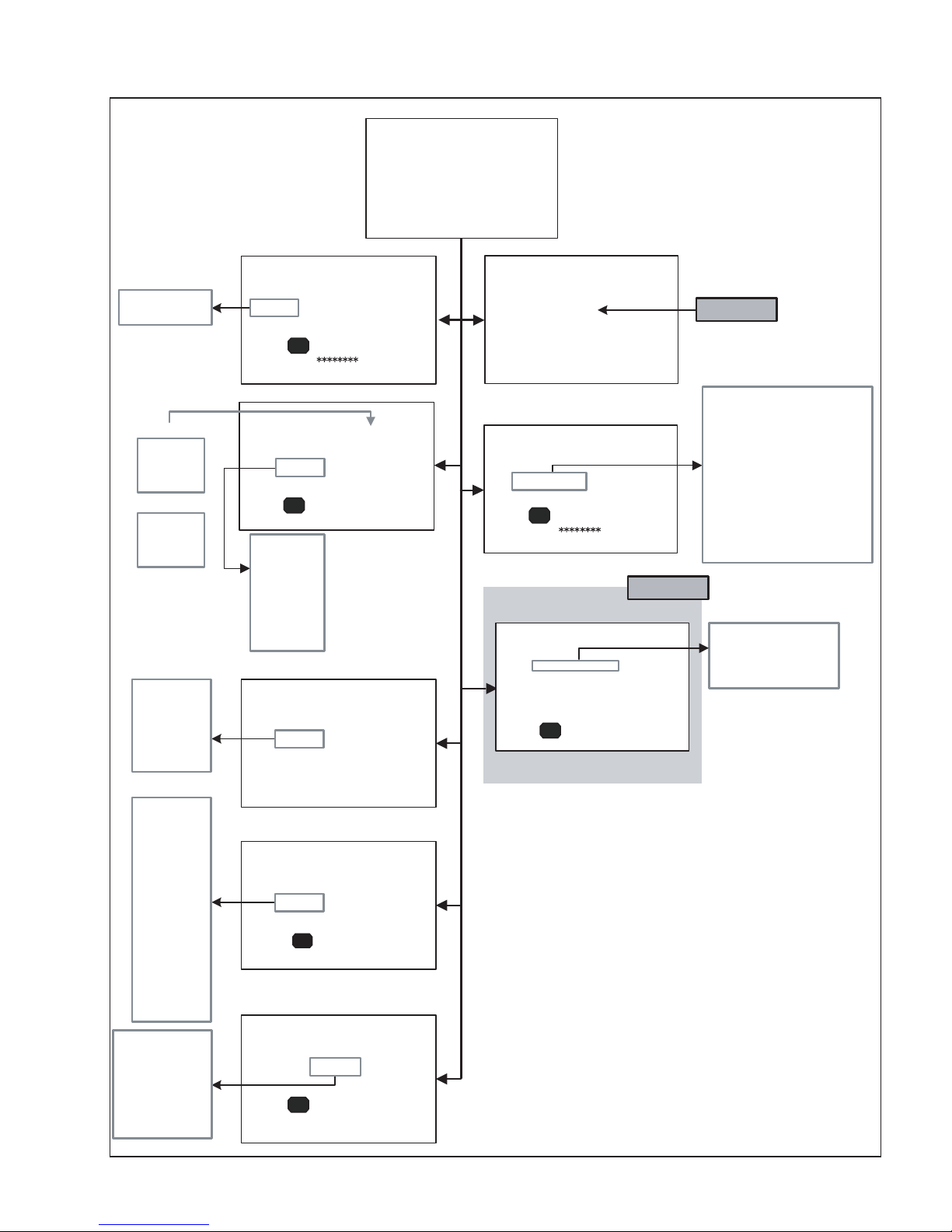
4.4 SERVICE MENU SCREEN
SERVICE MENU
SERVICE MENU
1. IF 2. V/C
3. AUDIO 4. DD/CM
5. VSM PRESET 6. STATUS
7. VNR 8. IP
9. SHIPPING (OFF) 0. BUS FREE
1-9 : SELECT i : EXIT
DDT01 ~ DDT34
CMT01 ~ CMT57
PICTURE MODE
BRIGHT
STD
SOFT
COLOUR TEMP.
COOL
NORMAL
WARM
1. SOFT
2. TELETEXT
3. ASPECT
4. IC
5. DEBUG
6. PANEL
4. DD/CM
DD/CM PAL
DDT01 0000
- / +
- / +
1. CONT
2. BRIGHT
3. SHARP
4. COLOUR
5.
6.
1.
2.
3.
- / +
: STORE i : EXIT
OK
5. VSM PRESET
VSM PRESET BRIGHT
1.CONT
OK
: STORE i : EXIT
TINT
B.LIGHT
WDR R
WDR G
WDR B
6. STATUS
STATUS
1.SOFT
OK
: SELECT i : EXIT
000
1.IF
IF SERVICE MENU
1. VCO
2. ATT ON/OFF
1-2 : SELECT i : EXIT
2. V/C
V/C
1. CUT OF R
OK
- / +
: STORE i : EXIT
1. ERROR LIMIT 0100
ERROR LIMIT =
C_AD_BITS =
OK
- / +
PAL
0000
3. AUDIO
AUDIO
: STORE i : EXIT
Do not adjust
0000
00000000
Do not adjust
1. CUT OF R
2. CUT OF G
3. CUT OF B
4. DRIVE R
5. DRIVE G
6. DRIVE B
7. TWN HI R
8. TWN HI B
9. BRIGHT
10. CONT
11. TWN BRG
12. TWN CNT
13. COLOUR
1. ERROR LIMIT
2. A2 ID THR
3. Q
-PEAK
4. SOUND SYSTEM B/G
14. HUE
15. BY GAIN
16. TWN COL
17. TWN TNT
18. B OF MR
19. B OF MB
20. B OF SR
21. B OF SB
22. M BOFST
23. M ROFST
S01 ~ S99
A01 ~ A17
PDA01 ~ PDA12
1. MYLV
2. ONMVF
3. MYCOR
4. MYGA
5. YEGON
6. YEGL
7. YLTL
8. MCLV
9. MCGA
10. MCCOR
11. CLTL
12. YNGA
13. COR_OF
14. LPF_OF
15. YCTL
16. YNCL
17. YNCON
PPA001 ~ PPA008
PPB001 ~ PPB036
PPC001 ~ PPC007
ADS001 ~ ADS034
IPA001 ~ IPA120
IPB001 ~ IPB088
IPC001 ~ IPC044
IPD001 ~ IPD058
- / +
IP PANOLAMIC PAL
0000 PPA001 0000
- / +
7. VNR
VNR LEVEL4
1.MYLV
OK
: STORE i : EXIT
: STORE i : EXIT
OK
000
8. IP
(No.YA169)1-23
Page 24
4.5 BASIC OPERATION OF THE SERVICE MENU MODE [USING REMOTE CONTROL UNIT]
SERVICE MENU SCREEN
4.5.1 TOOLS OF SERVICE MENU OPERATION
Operate the SERVICE MENU with the remote control unit.
4.5.2 HOW TO ENTER THE SERVICE MENU MODE
(1) Press the [INFORMATION] key and the [MUTING] key of
the REMOTE CONTROL UNIT simultaneously, and the
SERVICE MENU screen of Fig.4 will be displayed.
(2) When the Main Menu is displayed, press any key of the [1]
to [0] key to enter the corresponding menu mode.
*Press any of the [1] to [0] keys before the Service Menu
mode disappears.
(3) Select the service item using the [FUNCTION (/)] key.
(4) Set the value using the [FUNCTION (/)] key.
(5) Press the [OK] key to save the value.
4.5.5 SETTINGS OF THE SERVICE MENUS
1. IF (VCO adjustment, ATT setting)
[Do not adjust]
2. V/C (VIDEO setting)
[Do not change settings of items that are not included in
the "ADJUSTMENT PROCEDURE".]
Sets output data to the video circuit.
• [Function (/)] key
For scrolling up/down the setting items.
• [Function (/)] key
For scrolling up/down the setting values.
3. AUDIO (SOUND setting)
[Do not adjust]
4. DD/CM (Panel picture processing setting)
SERVICE MENU SCREEN
[Do not change settings of items that are not included in
the "ADJUSTMENT PROCEDURE".]
SERVICE MENU
1. IF 2. V/C
3. AUDIO 4. DD/CM
5. VSM PRESET 6. STATUS
7. VNR 8. IP
9. SHIPPING (OFF) 0. BUS FREE
Sets output data to the deflection circuit.
• [Function (/)] key
For scrolling up/down the setting items.
DDT01
• [Zoom (red)] key
For switching to the next item.
DDT01 CMT01
...
CMT01
...
1-9 : SELECT i : EXIT
Fig.4
4.5.3 HOW TO EXIT THE SERVICE MENU MODE
Press the [INFORMATION] key to exit the Service Menu mode.
4.5.4 SERVICE CONTROL KEY LAYOUT ON THE REMOTE
CONTROL UNIT
MUTING
1~0
INFOMATION
ZOOM
OK
FUNCTION /
FUNCTION /
• [Function (/)] key
For scrolling up/down the setting values.
5. VSM PRESET (PICTURE preset setting)
[Refer to page VSM PRESET SETTING.]
6. STATUS
(The version of software, the aspect, and the state of debugging are displayed. )
[Setting for this item is not required in servicing]
7. VNR (Noise reduction setting)
[Do not adjust]
Sets output data to the digital noise reduction circuit.
8. IP (DIST setting)
[Do not adjust]
Sets output data to the DIST circuit.
9. SHIPPING (OFF)
[Setting for this item is not required in servicing]
10. BUE FREE
[Setting for this item is not required in servicing]
Fig.5
1-24 (No.YA169)
Page 25
4.6 DEFAULT VALUES IN THE SERVICE MENU SETTING MODE
• Perform fine-tuning based on the "default values" using the remote control when in the SERVICE MENU setting mode.
• The "default values" serve only as an indication rough standard and therefore the values with which optimal display can be achieved
may be different from the default values. But, don't change the values that are not written in "ADJUSTMENT PROCEDURE". They
are fixed values.
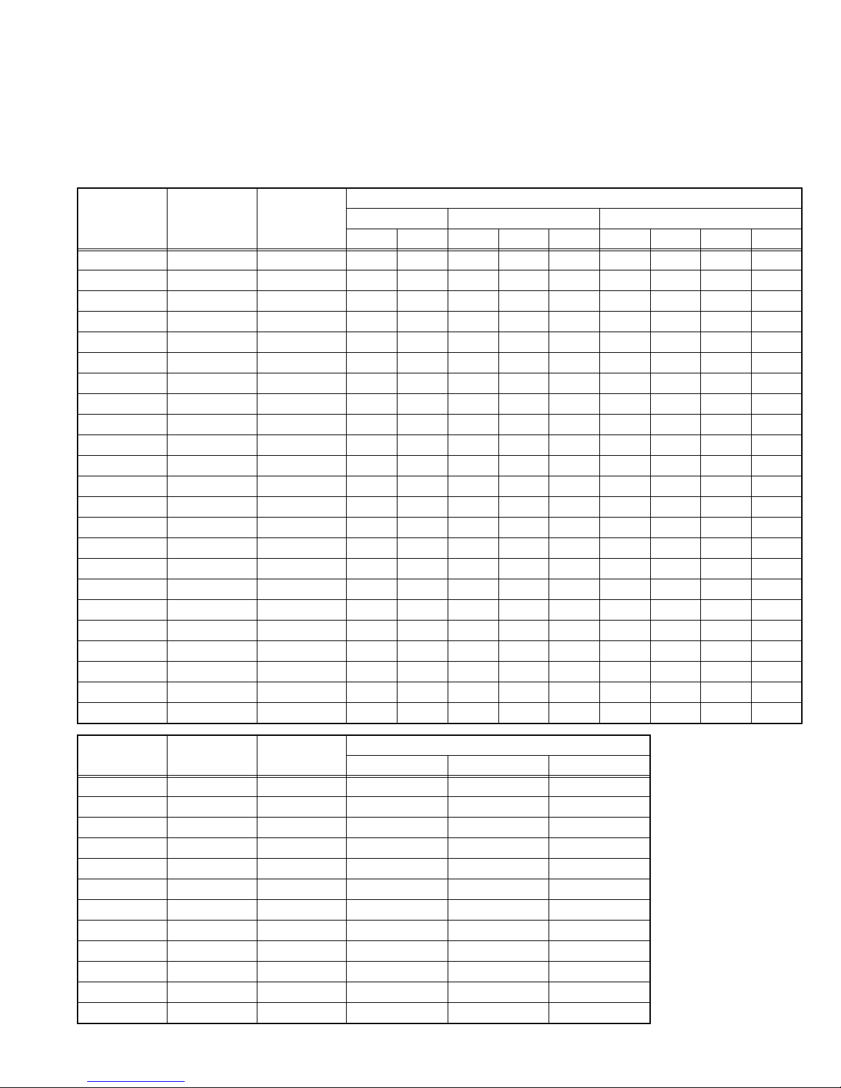
4.6.1 [2. V/C]
4.6.1.1 VIDEO SYSTEM
Setting value
Item No.
Item
name
Variable
range
TV EXT-1 / 2 / 3 EXT-4
PAL SECAM PAL SECAM NTSC 625i 525i 625p 525p
1 CUT OF R 0000~0255 0088 ←←←←0000 ←←←
2 CUT OF G 0000~0255 0101 ←←←←0000 ←←←
3 CUT OF B 0000~0255 0106 ←←←←0000 ←←←
4 DRIVE R 0000~0255 0129 ←←←←0000 ←←←
5 DRIVE G 0000~0255 0112 ←←←←0000 ←←←
6 DRIVE B 0000~0255 0110 ←←←←0000 ←←←
7 TWIN HI R 0000~0127 0071 ←←←←0000 ←←←
8 TWIN HI B 0000~0127 0068 ←←←←0000 ←←←
9 BRIGHT 0000~0255 0013 ←←←←0000 ←←←
10 CONT 0000~0015 0015 ←←←←0000 ←←←
11 TWN BRG 0000~0127 0075 ←←←←-002 ← 0000 ←
12 TWN CNT 0000~0015 0006 ←←←←0000 ←←←
13 COLOUR 0000~0015 0009 ← 0000 ← 0007 0000 ←←←
14 HUE 0000~0063 0000 ← 0034 ← 0034 0000 ←←←
15 BY GAIN 0000~0063 0043 ← 0000 ← 0043 0000 ←←←
16 TWN COL 0000~0015 0006 ← 0002 ← 0002 ←←←←
17 TWN TNT 0000~0063 0034 ← 0000 ← 0034 ←←←←
18 B OF MR 0000~0015 0008 ←←←←←←←←
19 B OF MB 0000~0015 0008 ←←←←←←←←
20 B OF SR 0000~0015 0008 ←←←←←←←←
21 B OF SB 0000~0015 0008 ←←←←←←←←
22 M BOFSET 0000~0007 0000 ←←←←←←←←
23 M ROFSET 0000~0007 0000 ←←←←←←←←
Item No.
Item
name
Variable
S01 COLOUR 0000~0255 0120 0120 0138
S02 HUE -128~0127 0000 0000 0000
S03 (NO DISPLAY) -128~0127 0000 0000 0000
S04 (NO DISPLAY) -128~0127 0000 0000 0000
S05 BRIGHT 0000~0255 0055 0055 0060
S06 CONT 0000~0255 0128 0128 0128
S07 (NO DISPLAY) -128~0127 0000 0000 0000
S08 (NO DISPLAY) -128~0127 0000 0000 0000
S09 (NO DISPLAY) 0000~0255 0140 0140 0138
S10 (NO DISPLAY) -128~0127 0000 0000 0000
S11 (NO DISPLAY) -128~0127 0006 0006 0006
S12 (NO DISPLAY) 0000~0003 0000 0000 0000
range
Setting value
PAL SECAM NTSC
(No.YA169)1-25
Page 26

Item No.
Item
name
Variable
range
PAL SECAM NTSC
Setting value
S13 R GAIN 0000~0255 0249 0249 0249
S14 (NO DISPLAY) -128~0127 0000 0000 0000
S15 G GAIN 0000~0255 0255 0255 0255
S16 (NO DISPLAY) -128~0127 0001 0001 0001
S17 B GAIN 0000~0255 0254 0254 0254
S18 (NO DISPLAY) -128~0127 0000 0000 0000
S19 (NO DISPLAY) 0000~0255 0128 0128 0128
S20 (NO DISPLAY) -128~0127 0000 0000 0000
S21 (NO DISPLAY) 0000~0255 0128 0128 0128
S22 (NO DISPLAY) -128~0127 0000 0000 0000
S23 (NO DISPLAY) 0000~0255 0128 0128 0128
S24 (NO DISPLAY) -128~0127 0000 0000 0000
S25 (NO DISPLAY) 0000/0001 0000 0000 0000
S26 (NO DISPLAY) 0000/0001 0000 0000 0000
S27 (NO DISPLAY) 0000/0001 0000 0000 0000
S28 (NO DISPLAY) 0000/0001 0000 0000 0000
S29 (NO DISPLAY) 0000/0001 0000 0000 0000
S30 (NO DISPLAY) 0000~0031 0000 0000 0000
S31 (NO DISPLAY) 0000~0063 0002 0002 0002
S32 (NO DISPLAY) 0000~0063 0019 0019 0018
S33 (NO DISPLAY) 0000/0001 0001 0001 0001
S34 (NO DISPLAY) 0000/0001 0001 0001 0001
S35 (NO DISPLAY) 0000/0001 0000 0000 0000
S36 (NO DISPLAY) 0000~0031 0000 0000 0000
S37 (NO DISPLAY) 0000~0255 0220 0220 0220
S38 (NO DISPLAY) 0000~0063 0050 0050 0050
S39 (NO DISPLAY) 0000~0063 0060 0060 0060
S40 (NO DISPLAY) 0000/0001 0001 0001 0001
S41 (NO DISPLAY) 0000/0001 0001 0001 0001
S42 (NO DISPLAY) 0000~0003 0001 0001 0001
S43 (NO DISPLAY) 0000~0031 0009 0009 0009
S44 (NO DISPLAY) 0000~0003 0001 0001 0001
S45 (NO DISPLAY) 0000~0003 0002 0002 0002
S46 (NO DISPLAY) 0000~0015 0015 0015 0015
S47 (NO DISPLAY) 0000~0015 0015 0015 0015
S48 (NO DISPLAY) 0000~0015 0015 0015 0015
S49 (NO DISPLAY) 0000/0001 0000 0000 0000
S50 (NO DISPLAY) 0000~0255 0002 0002 0002
S51 (NO DISPLAY) 0000/0001 0000 0000 0000
S52 (NO DISPLAY) 0000~0255 0076 0076 0076
S53 (NO DISPLAY) 0000/0001 0000 0000 0000
S54 (NO DISPLAY) 0000~0255 0006 0006 0006
S55 (NO DISPLAY) 0000/0001 0000 0000 0000
S56 (NO DISPLAY) 0000~0255 0094 0094 0094
S57 (NO DISPLAY) 0000~0255 0000 0000 0000
1-26 (No.YA169)
Page 27

Item No.
Item
name
Variable
range
PAL SECAM NTSC
Setting value
S58 (NO DISPLAY) 0000~0015 0000 0000 0000
S59 (NO DISPLAY) 0000~0255 0000 0000 0000
S60 (NO DISPLAY) 0000~0015 0000 0000 0000
S61 (NO DISPLAY) 0000/0001 0001 0001 0001
S62 (NO DISPLAY) 0000~0127 0016 0016 0016
S63 (NO DISPLAY) 0000/0001 0000 0000 0000
S64 (NO DISPLAY) 0000~0127 0000 0000 0000
S65 (NO DISPLAY) 0000~0003 0002 0002 0002
S66 (NO DISPLAY) 0000~0003 0001 0001 0001
S67 (NO DISPLAY) 0000~0003 0002 0002 0003
S68 (NO DISPLAY) 0000~0015 0000 0000 0000
S69 (NO DISPLAY) 0000~0063 0019 0019 0019
S70 (NO DISPLAY) 0000/0001 0001 0001 0001
S71 (NO DISPLAY) 0000~0255 0255 0255 0255
S72 (NO DISPLAY) 0000~0255 0255 0255 0255
S73 (NO DISPLAY) 0000~0255 0255 0255 0255
S74 (NO DISPLAY) 0000~0031 0000 0000 0000
S75 (NO DISPLAY) 0000~0031 0000 0000 0000
S76 (NO DISPLAY) -128~0128 0000 0000 0000
S77 (NO DISPLAY) -128~0128 0000 0000 0000
S78 (NO DISPLAY) 0000~0255 0255 0255 0255
S79 (NO DISPLAY) 0000~0255 0000 0000 0000
S80 (NO DISPLAY) 0000~0255 0255 0255 0255
S81 (NO DISPLAY) 0000~0255 0000 0000 0000
S82 (NO DISPLAY) 0000~0255 0255 0255 0255
S83 (NO DISPLAY) 0000~0255 0000 0000 0000
S84 (NO DISPLAY) 0000~0255 0216 0216 0216
S85 (NO DISPLAY) 0000~0255 0127 0127 0127
S86 (NO DISPLAY) 0000~0255 0127 0127 0127
S87 (NO DISPLAY) 0000~0003 0003 0003 0003
S88 (NO DISPLAY) 0000~0007 0000 0000 0000
S89 (NO DISPLAY) 0000~0255 0000 0000 0000
S90 (NO DISPLAY) 0000~0127 0000 0000 0000
S91 (NO DISPLAY) 0000~0007 0007 0007 0007
S92 (NO DISPLAY) 0000~0031 0031 0031 0031
S93 (NO DISPLAY) 0000~0007 0007 0007 0007
S94 (NO DISPLAY) 0000~0031 0031 0031 0031
S95 (NO DISPLAY) 0000~0255 0060 0060 0050
S96 (NO DISPLAY) 0000~0015 0003 0003 0006
S97 (NO DISPLAY) 0000~0063 0040 0040 0040
S98 (NO DISPLAY) 0000~0063 0000 0000 0000
S99 (NO DISPLAY) 0000~0063 0000 0000 0000
(No.YA169)1-27
Page 28
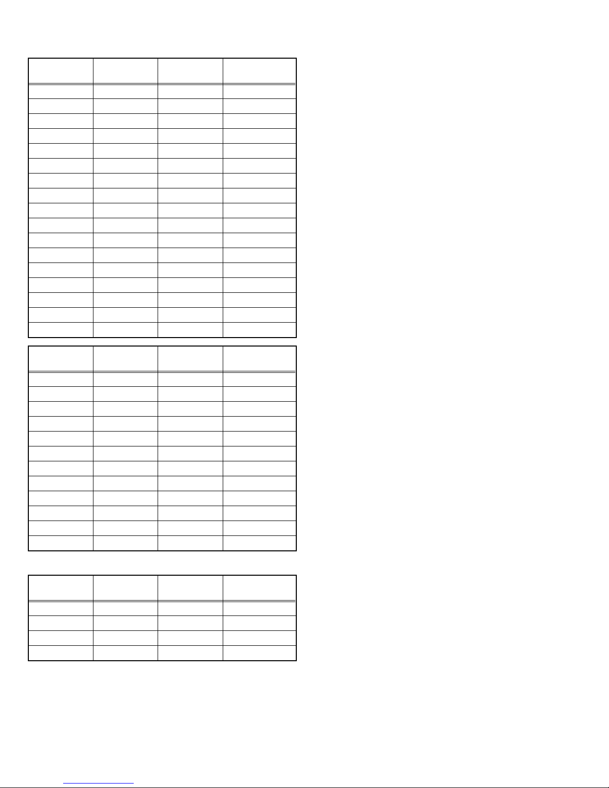
4.6.1.2 AUDIO SYSTEM
Item No.
Item
name
Variable
range
A01 (NO DISPLAY) 0000~0007 0001
A02 (NO DISPLAY) 0000~0007 0001
A03 (NO DISPLAY) 0000~0007 0001
A04 (NO DISPLAY) 0000~0007 0000
A05 (NO DISPLAY) 0000~0009 0003
A06 (NO DISPLAY) 0000~0015 0004
A07 (NO DISPLAY) 0000~0015 0006
A08 (NO DISPLAY) 0000~0015 0003
A09 (NO DISPLAY) 0000~0007 0006
A10 (NO DISPLAY) 0000~0007 0004
A11 (NO DISPLAY) 0000~0063 0063
A12 (NO DISPLAY) 0000~0063 0063
A13 (NO DISPLAY) 0000~0003 0000
A14 (NO DISPLAY) 0000~0007 0000
A15 (NO DISPLAY) 0000~0003 0000
A16 (NO DISPLAY) 0000~0003 0000
A17 (NO DISPLAY) 0000~0003 0000
Setting value
Item No.
Item
name
Variable
range
Setting value
PDA01 (NO DISPLAY) 0000~0255 0000
PDA02 (NO DISPLAY) 0000~0255 0031
PDA03 (NO DISPLAY) 0000~0255 0085
PDA04 (NO DISPLAY) 0000~0255 0004
PDA05 (NO DISPLAY) 0000/0001 0001
PDA06 (NO DISPLAY) 0000/0001 0000
PDA07 (NO DISPLAY) 0000~0255 0150
PDA08 (NO DISPLAY) 0000~0255 0150
PDA09 (NO DISPLAY) 0000~0255 0002
PDA10 (NO DISPLAY) 0000~0255 0060
PDA11 (NO DISPLAY) 0000~0255 0000
PDA12 (NO DISPLAY) 0000~0127 0000
4.6.2 [3.AUDIO] (MULTISOUND SYSTEM) (*All fixed)
Item No.
Item
name
Variable
range
Setting value
1 ERROR LIMIT 0000~0FF0 0100
2 A2 ID THR 0000~00FF 0019
3 Q-PEAK - -
4 SOUND LEVEL F00F~FFFF FFFF
1-28 (No.YA169)
Page 29

4.6.3 [4.DD/CM]
NOTE:
• For reference, initial setting values (except OSD-G/B/R) in the following conditions are written here.
• Input signal : PAL/SECAM/NTSC
• Picture mode : Standard
•Zoom : Full
• Multi screen : Single screen
• Colour temp. : Normal
Item No.
Item
name
Variable
range
PAL SECAM NTSC
Setting value
DDT01 (NO DISPLAY) 0000~0015 0000 0000 0000
DDT02 (NO DISPLAY) 0000~0255 0192 0192 0192
DDT03 (NO DISPLAY) 0000~0255 0255 0255 0255
DDT04 (NO DISPLAY) 0000~0255 0255 0255 0255
DDT05 (NO DISPLAY) 0000~0255 0255 0255 0000
DDT06 (NO DISPLAY) 0000~0255 0255 0255 0255
DDT07 (NO DISPLAY) 0000~0003 0000 0000 0000
DDT08 (NO DISPLAY) 0000~0255 0255 0255 0255
DDT09 (NO DISPLAY) 0000~0003 0000 0000 0000
DDT10 (NO DISPLAY) 0000~0255 0000 0000 0000
DDT11 (NO DISPLAY) 0000~0007 0000 0000 0000
DDT12 (NO DISPLAY) 0000~0255 0090 0090 0090
DDT13 (NO DISPLAY) 0000~0255 0000 0000 0000
DDT14 (NO DISPLAY) 0000~0003 0000 0000 0000
DDT15 (NO DISPLAY) 0000~0007 0000 0000 0000
DDT16 (NO DISPLAY) 0000~0255 0021 0021 0021
DDT17 (NO DISPLAY) 0000/0001 0000 0000 0000
DDT18 (NO DISPLAY) 0000/0001 0000 0000 0000
DDT19 (NO DISPLAY) 0000~0063 0001 0001 0001
DDT20 (NO DISPLAY) 0000~0015 0000 0000 0000
DDT21 (NO DISPLAY) 0000~0015 0000 0000 0000
DDT22 (NO DISPLAY) 0000~0015 0000 0000 0000
DDT23 (NO DISPLAY) 0000~0015 0000 0000 0000
DDT24 (NO DISPLAY) 0000/0001 0000 0000 0000
DDT25 (NO DISPLAY) 0000/0001 0000 0000 0000
DDT26 (NO DISPLAY) 0000/0001 0000 0000 0000
DDT27 (NO DISPLAY) 0000~0007 0000 0000 0000
DDT28 (NO DISPLAY) 0000~0255 0250 0250 0250
DDT29 (NO DISPLAY) 0000~0003 0000 0000 0000
DDT30 (NO DISPLAY) 0000/0001 0000 0000 0000
DDT31 (NO DISPLAY) 0000~0007 0005 0005 0005
DDT32 (NO DISPLAY) 0000~0255 0170 0170 0170
DDT33 (NO DISPLAY) 0000~0255 0000 0000 0000
DDT34 (NO DISPLAY) 0000~0255 0032 0032 0032
Item No.
Item
name
Variable
CMT01 (NO DISPLAY) 0000~0003 0000 0000 0000
CMT02 (NO DISPLAY) 0000~0255 0090 0090 0090
range
Setting value
PAL SECAM NTSC
(No.YA169)1-29
Page 30

Item No.
Item
name
Variable
range
PAL SECAM NTSC
Setting value
CMT03 (NO DISPLAY) 0000~0255 0030 0030 0020
CMT04 (NO DISPLAY) 0000~0255 0030 0030 0030
CMT05 (NO DISPLAY) 0000~0063 0059 0059 0060
CMT06 (NO DISPLAY) -128~0127 0005 0005 -002
CMT07 (NO DISPLAY) -128~0127 0002 0002 0010
CMT08 (NO DISPLAY) -128~0127 0000 0000 0000
CMT09 (NO DISPLAY) -128~0127 0000 0000 0003
CMT10 (NO DISPLAY) 0000~0003 0000 0000 0000
CMT11 (NO DISPLAY) 0000~0255 0160 0160 0160
CMT12 (NO DISPLAY) 0000~0255 0020 0020 0020
CMT13 (NO DISPLAY) 0000~0255 0020 0020 0020
CMT14 (NO DISPLAY) 0000~0063 0000 0000 0059
CMT15 (NO DISPLAY) -128~0127 0006 0006 -003
CMT16 (NO DISPLAY) -128~0127 0005 0005 0005
CMT17 (NO DISPLAY) -128~0127 0000 0000 0000
CMT18 (NO DISPLAY) -128~0127 0005 0005 0000
CMT19 (NO DISPLAY) 0000~0003 0000 0000 0000
CMT20 (NO DISPLAY) 0000~0255 0196 0196 0196
CMT21 (NO DISPLAY) 0000~0255 0030 0030 0030
CMT22 (NO DISPLAY) 0000~0255 0050 0050 0055
CMT23 (NO DISPLAY) 0000~0063 0061 0061 0000
CMT24 (NO DISPLAY) -128~0127 -003 -003 0003
CMT25 (NO DISPLAY) -128~0127 0022 0022 0012
CMT26 (NO DISPLAY) -128~0127 0006 0006 0005
CMT27 (NO DISPLAY) -128~0127 0020 0020 0012
CMT28 (NO DISPLAY) 0000~0003 0001 0001 0001
CMT29 (NO DISPLAY) 0000~0255 0070 0070 0070
CMT30 (NO DISPLAY) 0000~0255 0035 0035 0035
CMT31 (NO DISPLAY) 0000~0255 0040 0040 0040
CMT32 (NO DISPLAY) 0000~0063 0000 0000 0000
CMT33 (NO DISPLAY) -128~0127 0005 0005 0002
CMT34 (NO DISPLAY) -128~0127 0016 0016 0015
CMT35 (NO DISPLAY) -128~0127 0000 0000 -004
CMT36 (NO DISPLAY) -128~0127 0016 0016 0020
CMT37 (NO DISPLAY) 0000~0255 0064 0064 0064
CMT38 (NO DISPLAY) 0000~0255 0066 0066 0068
CMT39 (NO DISPLAY) 0000~0255 0078 0078 0078
CMT40 (NO DISPLAY) -128~0127 0000 0000 0000
CMT41 (NO DISPLAY) -128~0127 0005 0005 0004
CMT42 (NO DISPLAY) 0000/0001 0000 0000 0000
CMT43 (NO DISPLAY) 0000~0255 0080 0080 0080
CMT44 (NO DISPLAY) 0000/0001 0001 0001 0001
CMT45 (NO DISPLAY) 0000~0255 0080 0080 0080
CMT46 (NO DISPLAY) 0000/0001 0000 0000 0000
CMT47 (NO DISPLAY) 0000~0255 0080 0080 0080
1-30 (No.YA169)
Page 31

Item No.
Item
name
Variable
range
PAL SECAM NTSC
Setting value
CMT48 (NO DISPLAY) 0000/0001 0000 0000 0000
CMT49 (NO DISPLAY) 0000/0001 0001 0001 0001
CMT50 (NO DISPLAY) 0000~0031 0021 0021 0021
CMT51 (NO DISPLAY) 0000~0031 0021 0021 0021
CMT52 (NO DISPLAY) 0000/0001 0000 0000 0000
CMT53 (NO DISPLAY) 0000/0001 0000 0000 0000
CMT54 (NO DISPLAY) 0000~0003 0000 0000 0000
CMT55 (NO DISPLAY) 0000/0001 0000 0000 0000
CMT56 (NO DISPLAY) 0000/0001 0001 0001 0001
CMT57 (NO DISPLAY) 0000/0001 0000 0000 0000
4.6.4 [7.VNR] (*All fixed)
NOTE:
• For reference, initial setting values in the following conditions are written here.
• Input signal : PAL/SECAM/NTSC
• Picture mode : Standard
•Zoom : Full
• Multi screen : Single screen
• Colour temp. : Normal
Item No.
Item
name
Variable
range
PAL SECAM NTSC
Setting value
1 MYLV 0000~000F 000E 000E 000E
2 ONMVF 0000/0001 0001 0001 0001
3 MYCOR 0000~001F 0003 0003 0003
4 MYGA 0000~0003 0002 0002 0002
5 YEGON 0000/0001 0001 0001 0001
6 YEGL 0000~000F 0000 0000 0000
7 YLTL 0000~007F 0009 0009 0009
8 MCLV 0000~000F 0008 0008 0008
9 MCGA 0000~0003 0002 0002 0002
10 MCCOR 0000~001F 0003 0003 0003
11 CLTL 0000~007F 0009 0009 0009
12 YNGA 0000~0003 0003 0003 0003
13 COR_OF 0000/0001 0000 0000 0000
14 LPF_OF 0000/0001 0000 0000 0000
15 YCTL 0000~000F 0004 0004 0004
16 YNCL 0000~000F 000E 000E 000E
17 YNCON 0000/0001 0001 0001 0001
(No.YA169)1-31
Page 32

4.6.5 [8.IP] (*All fixed)
NOTE:
• For reference, initial setting values in the following conditions are written here.
• Input signal : PAL/SECAM/NTSC
• Picture mode : Standard
•Zoom : Full
• Multi screen : Single screen
• Colour temp. : Normal
Item No.
Item
name
Variable
range
PAL SECAM NTSC
Setting value
PPA001 (NO DISPLAY) 0000~00FF 0040 0040 0040
PPA002 (NO DISPLAY) 0000~00FF 0000 0000 0000
PPA003 (NO DISPLAY) 0000~00FF 0053 0053 005A
PPA004 (NO DISPLAY) 0000~00FF 0000 0000 0000
PPA005 (NO DISPLAY) 0000~00FF 0000 0000 0000
PPA006 (NO DISPLAY) 0000~00FF 0000 0000 0000
PPA007 (NO DISPLAY) 0000~00FF 0053 0053 005A
PPA008 (NO DISPLAY) 0000~00FF 0031 0031 0023
Item No.
Item
name
Variable
range
PAL SECAM NTSC
Setting value
PPB001 (NO DISPLAY) 0000~001F 0000 0000 0000
PPB002 (NO DISPLAY) 0000~00FF 0000 0000 0000
PPB003 (NO DISPLAY) 0000~00FF 0000 0000 0000
PPB004 (NO DISPLAY) 0000~001F 0000 0000 0000
PPB005 (NO DISPLAY) 0000~00FF 0000 0000 0000
PPB006 (NO DISPLAY) 0000~00FF 0000 0000 0000
PPB007 (NO DISPLAY) 0000~001F 0000 0000 0000
PPB008 (NO DISPLAY) 0000~00FF 0000 0000 0000
PPB009 (NO DISPLAY) 0000~00FF 0000 0000 0000
PPB010 (NO DISPLAY) 0000~001F 0000 0000 0000
PPB011 (NO DISPLAY) 0000~00FF 0000 0000 0000
PPB012 (NO DISPLAY) 0000~00FF 0000 0000 0000
PPB013 (NO DISPLAY) 0000~001F 0000 0000 0000
PPB014 (NO DISPLAY) 0000~00FF 0000 0000 0000
PPB015 (NO DISPLAY) 0000~00FF 0000 0000 0000
PPB016 (NO DISPLAY) 0000~001F 0000 0000 0000
PPB017 (NO DISPLAY) 0000~00FF 0000 0000 0000
PPB018 (NO DISPLAY) 0000~00FF 0000 0000 0000
PPB019 (NO DISPLAY) 0000~001F 0000 0000 0000
PPB020 (NO DISPLAY) 0000~00FF 0000 0000 0000
PPB021 (NO DISPLAY) 0000~00FF 0000 0000 0000
PPB022 (NO DISPLAY) 0000~001F 0000 0000 0000
PPB023 (NO DISPLAY) 0000~00FF 0000 0000 0000
PPB024 (NO DISPLAY) 0000~00FF 0000 0000 0000
PPB025 (NO DISPLAY) 0000~001F 0000 0000 0000
PPB026 (NO DISPLAY) 0000~00FF 0000 0000 0000
PPB027 (NO DISPLAY) 0000~00FF 0000 0000 0000
PPB028 (NO DISPLAY) 0000~001F 0000 0000 0000
1-32 (No.YA169)
Page 33

Item No.
Item
name
Variable
range
PAL SECAM NTSC
Setting value
PPB029 (NO DISPLAY) 0000~00FF 0000 0000 0000
PPB030 (NO DISPLAY) 0000~00FF 0000 0000 0000
PPB031 (NO DISPLAY) 0000~001F 0000 0000 0000
PPB032 (NO DISPLAY) 0000~00FF 0000 0000 0000
PPB033 (NO DISPLAY) 0000~00FF 0000 0000 0000
PPB034 (NO DISPLAY) 0000~001F 0000 0000 0000
PPB035 (NO DISPLAY) 0000~00FF 0000 0000 0000
PPB036 (NO DISPLAY) 0000~00FF 0000 0000 0000
Item No.
Item
name
Variable
range
PAL SECAM NTSC
Setting value
PPC001 (NO DISPLAY) 0000~000F 0000 0000 0000
PPC002 (NO DISPLAY) 0000~00FF 000E 000E 000E
PPC003 (NO DISPLAY) 0000~00FF 0000 0000 0000
PPC004 (NO DISPLAY) 0000~000F 0000 0000 0000
PPC005 (NO DISPLAY) 0000~00FF 007C 007C 007C
PPC006 (NO DISPLAY) 0000~000F 0000 0000 0000
PPC007 (NO DISPLAY) 0000~00FF 0000 0000 0000
Item No.
Item
name
Variable
range
PAL SECAM NTSC
Setting value
ADS001 (NO DISPLAY) 0000~00FF 00D7 00D7 00D7
ADS002 (NO DISPLAY) 0000~000F 0000F 0000F 0000F
ADS003 (NO DISPLAY) 0000~0003 0001 0001 0001
ADS004 (NO DISPLAY) 0000~0007 0005 0005 0005
ADS005 (NO DISPLAY) 0000~001F 0016 0016 0016
ADS006 (NO DISPLAY) 0000~00FF 0028 0028 0028
ADS007 (NO DISPLAY) 0000~00FF 0096 0096 0096
ADS008 (NO DISPLAY) 0000~00FF 0020 0020 0020
ADS009 (NO DISPLAY) 0000~00FF 000FF 000FF 000FF
ADS010 (NO DISPLAY) 0000~00FF 000FF 000FF 000FF
ADS011 (NO DISPLAY) 0000~00FF 000FF 000FF 000FF
ADS012 (NO DISPLAY) 0000~007F 004A 004A 004A
ADS013 (NO DISPLAY) 0000~007F 0051 0051 0051
ADS014 (NO DISPLAY) 0000~007F 0042 0042 0042
ADS015 (NO DISPLAY) 0000/0001 0001 0001 0001
ADS016 (NO DISPLAY) 0000/0001 0001 0001 0001
ADS017 (NO DISPLAY) 0000/0001 0000 0000 0000
ADS018 (NO DISPLAY) 0000/0001 0001 0001 0001
ADS019 (NO DISPLAY) 0000/0001 0000 0000 0000
ADS020 (NO DISPLAY) 0000/0001 0000 0000 0000
ADS021 (NO DISPLAY) 0000/0001 0001 0001 0001
ADS022 (NO DISPLAY) 0000/0001 0000 0000 0000
ADS023 (NO DISPLAY) 0000/0001 0000 0000 0000
ADS024 (NO DISPLAY) 0000/0001 0001 0001 0001
ADS025 (NO DISPLAY) 0000/0001 0000 0000 0000
(No.YA169)1-33
Page 34

Item No.
Item
name
Variable
range
PAL SECAM NTSC
Setting value
ADS026 (NO DISPLAY) 0000/0001 0001 0001 0001
ADS027 (NO DISPLAY) 0000/0001 0001 0001 0001
ADS028 (NO DISPLAY) 0000/0001 0001 0001 0001
ADS029 (NO DISPLAY) 0000/0001 0000 0000 0000
ADS030 (NO DISPLAY) 0000~001F 0003 0003 0003
ADS031 (NO DISPLAY) 0000/0001 0001 0001 0001
ADS032 (NO DISPLAY) 0000/0001 0000 0000 0000
ADS033 (NO DISPLAY) 0000/0001 0001 0001 0001
ADS034 (NO DISPLAY) 0000~00FF 0032 0032 0032
Item No.
Item
name
Variable
range
PAL SECAM NTSC
Setting value
IPA001 (NO DISPLAY) 0000/0001 0001 0001 0001
IPA002 (NO DISPLAY) 0000~003F 0022 0022 0022
IPA003 (NO DISPLAY) 0000~003F 0022 0022 0022
IPA004 (NO DISPLAY) 0000~003F 0000 0000 0022
IPA005 (NO DISPLAY) 0000~0003 0000 0000 0000
IPA006 (NO DISPLAY) 0000~0003 0000 0000 0000
IPA007 (NO DISPLAY) 0000~000F 000F 000F 000F
IPA008 (NO DISPLAY) 0000~003F 0008 0008 0008
IPA009 (NO DISPLAY) 0000~003F 000B 000B 0005
IPA010 (NO DISPLAY) 0000~003F 0019 0019 0019
IPA011 (NO DISPLAY) 0000~003F 0015 0015 0015
IPA012 (NO DISPLAY) 0000~003F 0022 0022 0022
IPA013 (NO DISPLAY) 0000~0003 0001 0001 0001
IPA014 (NO DISPLAY) 0000~0003 0001 0001 0001
IPA015 (NO DISPLAY) 0000~000F 000F 000F 000F
IPA016 (NO DISPLAY) 0000~003F 0003 0003 0003
IPA017 (NO DISPLAY) 0000/0001 0001 0001 0001
IPA018 (NO DISPLAY) 0000~003F 000D 000D 000D
IPA019 (NO DISPLAY) 0000/0001 0001 0001 0001
IPA020 (NO DISPLAY) 0000/0001 0001 0001 0001
IPA021 (NO DISPLAY) 0000~003F 0030 0030 0030
IPA022 (NO DISPLAY) 0000~0003 0001 0001 0001
IPA023 (NO DISPLAY) 0000~003F 000A 000A 000A
IPA024 (NO DISPLAY) 0000/0001 0001 0001 0001
IPA025 (NO DISPLAY) 0000/0001 0001 0001 0001
IPA026 (NO DISPLAY) 0000~003F 0030 0030 0030
IPA027 (NO DISPLAY) 0000~0003 0001 0001 0001
IPA028 (NO DISPLAY) 0000~003F 000A 000A 000A
IPA029 (NO DISPLAY) 0000~003F 0000 0000 0000
IPA030 (NO DISPLAY) 0000~000F 0000 0000 0000
IPA031 (NO DISPLAY) 0000~0007 0000 0000 0000
IPA032 (NO DISPLAY) 0000~003F 0000 0000 0000
IPA033 (NO DISPLAY) 0000/0001 0000 0000 0000
IPA034 (NO DISPLAY) 0000~003F 0000 0000 0000
1-34 (No.YA169)
Page 35

Item No.
Item
name
Variable
range
PAL SECAM NTSC
Setting value
IPA035 (NO DISPLAY) 0000/0001 0001 0001 0001
IPA036 (NO DISPLAY) 0000~003F 000D 000D 000D
IPA037 (NO DISPLAY) 0000~003F 000D 000D 000D
IPA038 (NO DISPLAY) 0000~003F 0010 0010 0010
IPA039 (NO DISPLAY) 0000~0003 0001 0001 0001
IPA040 (NO DISPLAY) 0000~0003 0001 0001 0001
IPA041 (NO DISPLAY) 0000~000F 000F 000F 000F
IPA042 (NO DISPLAY) 0000~003F 0005 0005 0005
IPA043 (NO DISPLAY) 0000~003F 0008 0008 0008
IPA044 (NO DISPLAY) 0000~003F 0020 0020 0020
IPA045 (NO DISPLAY) 0000~003F 0020 0020 0020
IPA046 (NO DISPLAY) 0000~003F 0020 0020 0020
IPA047 (NO DISPLAY) 0000~0003 0002 0002 0002
IPA048 (NO DISPLAY) 0000~0003 0002 0002 0002
IPA049 (NO DISPLAY) 0000~000F 0007 0007 0007
IPA050 (NO DISPLAY) 0000~003F 0008 0008 0008
IPA051 (NO DISPLAY) 0000/0001 0001 0001 0001
IPA052 (NO DISPLAY) 0000~003F 0008 0008 0008
IPA053 (NO DISPLAY) 0000/0001 0001 0001 0001
IPA054 (NO DISPLAY) 0000/0001 0001 0001 0001
IPA055 (NO DISPLAY) 0000~003F 0015 0015 0015
IPA056 (NO DISPLAY) 0000~0003 0000 0000 0000
IPA057 (NO DISPLAY) 0000~003F 000A 000A 000A
IPA058 (NO DISPLAY) 0000/0001 0001 0001 0001
IPA059 (NO DISPLAY) 0000/0001 0001 0001 0001
IPA060 (NO DISPLAY) 0000~003F 0015 0015 0015
IPA061 (NO DISPLAY) 0000~0003 0000 0000 0000
IPA062 (NO DISPLAY) 0000~003F 000A 000A 000A
IPA063 (NO DISPLAY) 0000~003F 003F 003F 003F
IPA064 (NO DISPLAY) 0000~000F 0006 0006 0006
IPA065 (NO DISPLAY) 0000~0007 0001 0001 0001
IPA066 (NO DISPLAY) 0000~003F 0008 0008 0008
IPA067 (NO DISPLAY) 0000/0001 0001 0001 0001
IPA068 (NO DISPLAY) 0000~003F 0027 0027 0027
IPA069 (NO DISPLAY) 0000~0003 0000 0000 0000
IPA070 (NO DISPLAY) 0000~00FF 0000 0000 0000
IPA071 (NO DISPLAY) 0000~000F 0005 0005 0005
IPA072 (NO DISPLAY) 0000~00FF 00DB 00DB 00DB
IPA073 (NO DISPLAY) 0000/0001 0000 0000 0000
IPA074 (NO DISPLAY) 0000/0001 0000 0000 0000
IPA075 (NO DISPLAY) 0000~00FF 0018 0018 0018
IPA076 (NO DISPLAY) 0000/0001 0000 0000 0000
IPA077 (NO DISPLAY) 0000/0001 0000 0000 0000
IPA078 (NO DISPLAY) 0000/0001 0000 0000 0000
IPA079 (NO DISPLAY) 0000/0001 0000 0000 0000
(No.YA169)1-35
Page 36

Item No.
Item
name
Variable
range
PAL SECAM NTSC
Setting value
IPA080 (NO DISPLAY) 0000/0001 0000 0000 0000
IPA081 (NO DISPLAY) 0000/0001 0000 0000 0000
IPA082 (NO DISPLAY) 0000/0001 0000 0000 0000
IPA083 (NO DISPLAY) 0000/0001 0000 0000 0000
IPA084 (NO DISPLAY) 0000/0001 0000 0000 0000
IPA085 (NO DISPLAY) 0000/0001 0000 0000 0000
IPA086 (NO DISPLAY) 0000/0001 0000 0000 0000
IPA087 (NO DISPLAY) 0000/0001 0000 0000 0000
IPA088 (NO DISPLAY) 0000/0001 0000 0000 0000
IPA089 (NO DISPLAY) 0000/0001 0000 0000 0000
IPA090 (NO DISPLAY) 0000/0001 0000 0000 0000
IPA091 (NO DISPLAY) 0000~000F 0000 0000 0000
IPA092 (NO DISPLAY) 0000~00FF 0000 0000 0000
IPA093 (NO DISPLAY) 0000~000F 000F 000F 000F
IPA094 (NO DISPLAY) 0000~00FF 00FF 00FF 00FF
IPA095 (NO DISPLAY) 0000~000F 0000 0000 0000
IPA096 (NO DISPLAY) 0000~00FF 0000 0000 0000
IPA097 (NO DISPLAY) 0000~000F 000F 000F 000F
IPA098 (NO DISPLAY) 0000~00FF 00FF 00FF 00FF
IPA099 (NO DISPLAY) 0000~000F 0000 0000 0000
IPA100 (NO DISPLAY) 0000~00FF 0000 0000 0000
IPA101 (NO DISPLAY) 0000~000F 0000 0000 0000
IPA102 (NO DISPLAY) 0000~00FF 0000 0000 0000
IPA103 (NO DISPLAY) 0000~000F 0000 0000 0000
IPA104 (NO DISPLAY) 0000~00FF 0000 0000 0000
IPA105 (NO DISPLAY) 0000~000F 0000 0000 0000
IPA106 (NO DISPLAY) 0000~00FF 0000 0000 0000
IPA107 (NO DISPLAY) 0000~000F 0000 0000 0000
IPA108 (NO DISPLAY) 0000~00FF 0080 0080 0080
IPA109 (NO DISPLAY) 0000~000F 0000 0000 0000
IPA110 (NO DISPLAY) 0000~00FF 0040 0040 0040
IPA111 (NO DISPLAY) 0000~000F 0005 0005 0005
IPA112 (NO DISPLAY) 0000~00FF 0040 0040 0040
IPA113 (NO DISPLAY) 0000~000F 0000 0000 0000
IPA114 (NO DISPLAY) 0000~00FF 00C0 00C0 00C0
IPA115 (NO DISPLAY) 0000~000F 0002 0002 0002
IPA116 (NO DISPLAY) 0000~00FF 00EF 00EF 00EF
IPA117 (NO DISPLAY) 0000/0001 0000 0000 0000
IPA118 (NO DISPLAY) 0000/0001 0000 0000 0000
IPA119 (NO DISPLAY) 0000/0001 0000 0000 0000
IPA120 (NO DISPLAY) 0000/0001 0000 0000 0000
1-36 (No.YA169)
Page 37

Item No.
Item
name
Variable
range
PAL SECAM NTSC
Setting value
IPB001 (NO DISPLAY) 0000~00FF 0001 0001 0001
IPB002 (NO DISPLAY) 0000~00FF 0001 0001 0003
IPB003 (NO DISPLAY) 0000~000F 0000 0000 0000
IPB004 (NO DISPLAY) 0000~00FF 0000 0000 0000
IPB005 (NO DISPLAY) 0000~000F 0000 0000 0000
IPB006 (NO DISPLAY) 0000~00FF 00EC 00EC 00ED
IPB007 (NO DISPLAY) 0000~000F 0002 0002 0002
IPB008 (NO DISPLAY) 0000~00FF 0000 0000 0000
IPB009 (NO DISPLAY) 0000~000F 0000 0000 0000
IPB010 (NO DISPLAY) 0000~00FF 0000 0000 0000
IPB011 (NO DISPLAY) 0000~000F 0000 0000 0000
IPB012 (NO DISPLAY) 0000~00FF 0000 0000 0000
IPB013 (NO DISPLAY) 0000~000F 0000 0000 0000
IPB014 (NO DISPLAY) 0000~00FF 0000 0000 0000
IPB015 (NO DISPLAY) 0000~000F 0000 0000 0000
IPB016 (NO DISPLAY) 0000~00FF 0000 0000 0000
IPB017 (NO DISPLAY) 0000~000F 0000 0000 0000
IPB018 (NO DISPLAY) 0000~00FF 0000 0000 0000
IPB019 (NO DISPLAY) 0000~000F 0000 0000 0000
IPB020 (NO DISPLAY) 0000~00FF 0000 0000 0000
IPB021 (NO DISPLAY) 0000~000F 0000 0000 0000
IPB022 (NO DISPLAY) 0000~00FF 0000 0000 0000
IPB023 (NO DISPLAY) 0000~000F 0000 0000 0000
IPB024 (NO DISPLAY) 0000~00FF 0000 0000 0000
IPB025 (NO DISPLAY) 0000~000F 0000 0000 0000
IPB026 (NO DISPLAY) 0000~00FF 0000 0000 0000
IPB027 (NO DISPLAY) 0000~000F 000F 000F 000F
IPB028 (NO DISPLAY) 0000~00FF 0000 0000 0000
IPB029 (NO DISPLAY) 0000~000F 0000 0000 0000
IPB030 (NO DISPLAY) 0000~00FF 0000 0000 0000
IPB031 (NO DISPLAY) 0000~000F 0000 0000 0000
IPB032 (NO DISPLAY) 0000~00FF 0000 0000 0000
IPB033 (NO DISPLAY) 0000~000F 0000 0000 0000
IPB034 (NO DISPLAY) 0000~00FF 0000 0000 0000
IPB035 (NO DISPLAY) 0000~000F 0000 0000 0000
IPB036 (NO DISPLAY) 0000~00FF 0000 0000 0000
IPB037 (NO DISPLAY) 0000/0001 0000 0000 0000
IPB038 (NO DISPLAY) 0000~0007 0000 0000 0000
IPB039 (NO DISPLAY) 0000~000F 0000 0000 0000
IPB040 (NO DISPLAY) 0000~000F 0000 0000 0000
IPB041 (NO DISPLAY) 0000~000F 0000 0000 0000
IPB042 (NO DISPLAY) 0000~00FF 0000 0000 0000
IPB043 (NO DISPLAY) 0000~000F 0000 0000 0000
IPB044 (NO DISPLAY) 0000~00FF 0000 0000 0000
IPB045 (NO DISPLAY) 0000~000F 0001 0001 0001
(No.YA169)1-37
Page 38

Item No.
Item
name
Variable
range
PAL SECAM NTSC
Setting value
IPB046 (NO DISPLAY) 0000~00FF 008B 008B 008B
IPB047 (NO DISPLAY) 0000~000F 0000 0000 0000
IPB048 (NO DISPLAY) 0000~00FF 0000 0000 0000
IPB049 (NO DISPLAY) 0000~000F 0000 0000 0000
IPB050 (NO DISPLAY) 0000~00FF 000F 000F 000F
IPB051 (NO DISPLAY) 0000~000F 0006 0006 0006
IPB052 (NO DISPLAY) 0000~00FF 0000 0000 0000
IPB053 (NO DISPLAY) 0000~000F 0000 0000 0000
IPB054 (NO DISPLAY) 0000~00FF 0000 0000 0000
IPB055 (NO DISPLAY) 0000~000F 0000 0000 0000
IPB056 (NO DISPLAY) 0000~00FF 0000 0000 0000
IPB057 (NO DISPLAY) 0000~000F 0000 0000 0000
IPB058 (NO DISPLAY) 0000~00FF 0000 0000 0000
IPB059 (NO DISPLAY) 0000~0007 0000 0000 0000
IPB060 (NO DISPLAY) 0000~0003 0000 0000 0000
IPB061 (NO DISPLAY) 0000~0003 0000 0000 0000
IPB062 (NO DISPLAY) 0000/0001 0000 0000 0000
IPB063 (NO DISPLAY) 0000~00FF 0000 0000 0000
IPB064 (NO DISPLAY) 0000~00FF 0000 0000 0000
IPB065 (NO DISPLAY) 0000~00FF 0000 0000 0000
IPB066 (NO DISPLAY) 0000/0001 00C8 00C8 00C8
IPB067 (NO DISPLAY) 0000~000F 0006 0006 0006
IPB068 (NO DISPLAY) 0000~000F 0040 0040 0040
IPB069 (NO DISPLAY) 0000~000F 0001 0001 0001
IPB070 (NO DISPLAY) 0000~000F 0000 0000 0000
IPB071 (NO DISPLAY) 0000~00FF 0001 0001 0001
IPB072 (NO DISPLAY) 0000~000F 0000 0000 0000
IPB073 (NO DISPLAY) 0000~00FF 0050 0050 0050
IPB074 (NO DISPLAY) 0000/0001 0080 0080 0080
IPB075 (NO DISPLAY) 0000/0001 0080 0080 0080
IPB076 (NO DISPLAY) 0000/0001 0000 0000 0000
IPB077 (NO DISPLAY) 0000~000F 0000 0000 0000
IPB078 (NO DISPLAY) 0000/0001 0000 0000 0000
IPB079 (NO DISPLAY) 0000~00FF 0000 0000 0000
IPB080 (NO DISPLAY) 0000~000F 000F 000F 000F
IPB081 (NO DISPLAY) 0000~00FF 0000 0000 0000
IPB082 (NO DISPLAY) 0000~000F 0000 0000 0000
IPB083 (NO DISPLAY) 0000~00FF 0000 0000 0000
IPB084 (NO DISPLAY) 0000/0001 0000 0000 0000
IPB085 (NO DISPLAY) 0000/0001 0000 0000 0000
IPB086 (NO DISPLAY) 0000/0001 0000 0000 0000
IPB087 (NO DISPLAY) 0000~000F 000B 000B 000B
IPB088 (NO DISPLAY) 0000/0001 0001 0001 0001
1-38 (No.YA169)
Page 39

Item No.
Item
name
Variable
range
PAL SECAM NTSC
Setting value
IPC001 (NO DISPLAY) 0000~0003 0002 0002 0002
IPC002 (NO DISPLAY) 0000~00FF 00EA 00EA 00EA
IPC003 (NO DISPLAY) 0000/0001 0000 0000 0000
IPC004 (NO DISPLAY) 0000/0001 0000 0000 0000
IPC005 (NO DISPLAY) 0000~000F 0000 0000 0000
IPC006 (NO DISPLAY) 0000~00FF 0000 0000 0000
IPC007 (NO DISPLAY) 0000~000F 0005 0005 0005
IPC008 (NO DISPLAY) 0000~00FF 00DB 00DB 00DB
IPC009 (NO DISPLAY) 0000~000F 0007 0007 0006
IPC010 (NO DISPLAY) 0000~00FF 00B9 00B9 0071
IPC011 (NO DISPLAY) 0000~000F 0004 0004 0004
IPC012 (NO DISPLAY) 0000~00FF 00CE 00CE 00CE
IPC013 (NO DISPLAY) 0000~0003 0000 0000 0000
IPC014 (NO DISPLAY) 0000/0001 0000 0000 0000
IPC015 (NO DISPLAY) 0000/0001 0001 0001 0001
IPC016 (NO DISPLAY) 0000~00FF 001F 001F 0003
IPC017 (NO DISPLAY) 0000/0001 0000 0000 0000
IPC018 (NO DISPLAY) 0000~007F 0000 0000 0000
IPC019 (NO DISPLAY) 0000/0001 0000 0000 0000
IPC020 (NO DISPLAY) 0000~007F 0001 0001 0001
IPC021 (NO DISPLAY) 0000~000F 0000 0000 0000
IPC022 (NO DISPLAY) 0000~00FF 00FE 00FE 00FE
IPC023 (NO DISPLAY) 0000~0003 0000 0000 0000
IPC024 (NO DISPLAY) 0000~00FF 005C 005C 0040
IPC025 (NO DISPLAY) 0000/0001 0000 0000 0000
IPC026 (NO DISPLAY) 0000~007F 0020 0020 0020
IPC027 (NO DISPLAY) 0000/0001 0000 0000 0000
IPC028 (NO DISPLAY) 0000~007F 0000 0000 0000
IPC029 (NO DISPLAY) 0000/0001 0001 0001 0001
IPC030 (NO DISPLAY) 0000/0001 0000 0000 0000
IPC031 (NO DISPLAY) 0000/0001 0000 0000 0000
IPC032 (NO DISPLAY) 0000/0001 0000 0000 0000
IPC033 (NO DISPLAY) 0000/0001 0000 0000 0000
IPC034 (NO DISPLAY) 0000/0001 0000 0000 0000
IPC035 (NO DISPLAY) 0000/0001 0000 0000 0000
IPC036 (NO DISPLAY) 0000/0001 0000 0000 0000
IPC037 (NO DISPLAY) 0000/0001 0000 0000 0000
IPC038 (NO DISPLAY) 0000/0001 0000 0000 0000
IPC039 (NO DISPLAY) 0000/0001 0000 0000 0000
IPC040 (NO DISPLAY) 0000/0001 0000 0000 0000
IPC041 (NO DISPLAY) 0000/0001 0000 0000 0000
IPC042 (NO DISPLAY) 0000/0001 0000 0000 0000
IPC043 (NO DISPLAY) 0000/0001 0000 0000 0000
IPC044 (NO DISPLAY) 0000/0001 0000 0000 0000
(No.YA169)1-39
Page 40

Item No.
Item
name
Variable
range
PAL SECAM NTSC
Setting value
IPD001 (NO DISPLAY) 0000~00FF 0040 0040 0040
IPD002 (NO DISPLAY) 0000~00FF 0000 0000 0000
IPD003 (NO DISPLAY) 0000~00FF 0000 0000 0000
IPD004 (NO DISPLAY) 0000~0007 0000 0000 0000
IPD005 (NO DISPLAY) 0000~00FF 0000 0000 0000
IPD006 (NO DISPLAY) 0000~0007 0006 0006 0006
IPD007 (NO DISPLAY) 0000~00FF 0018 0018 0018
IPD008 (NO DISPLAY) 0000/0001 0000 0000 0000
IPD009 (NO DISPLAY) 0000~000F 0001 0001 0001
IPD010 (NO DISPLAY) 0000~00FF 0062 0062 0062
IPD011 (NO DISPLAY) 0000~000F 0005 0005 0005
IPD012 (NO DISPLAY) 0000~00FF 002B 002B 002B
IPD013 (NO DISPLAY) 0000~0007 0000 0000 0000
IPD014 (NO DISPLAY) 0000~0007 0000 0000 0000
IPD015 (NO DISPLAY) 0000/0001 0002 0002 0002
IPD016 (NO DISPLAY) 0000/0001 0002 0002 0002
IPD017 (NO DISPLAY) 0000~00FF 0002 0002 0002
IPD018 (NO DISPLAY) 0000~0007 0002 0002 0002
IPD019 (NO DISPLAY) 0000~00FF 0002 0002 0002
IPD020 (NO DISPLAY) 0000~0007 0002 0002 0002
IPD021 (NO DISPLAY) 0000~00FF 0070 0070 0070
IPD022 (NO DISPLAY) 0000/0001 0080 0080 0080
IPD023 (NO DISPLAY) 0000~000F 0080 0080 0080
IPD024 (NO DISPLAY) 0000~00FF 0070 0070 0070
IPD025 (NO DISPLAY) 0000~000F 0060 0060 0060
IPD026 (NO DISPLAY) 0000~00FF 0050 0050 0050
IPD027 (NO DISPLAY) 0000~00FF 0040 0040 0040
IPD028 (NO DISPLAY) 0000~0007 0000 0000 0000
IPD029 (NO DISPLAY) 0000~0007 0000 0000 0000
IPD030 (NO DISPLAY) 0000/0001 0000 0000 0000
IPD031 (NO DISPLAY) 0000/0001 0000 0000 0000
IPD032 (NO DISPLAY) 0000~00FF 0000 0000 0000
IPD033 (NO DISPLAY) 0000/0001 0000 0000 0000
IPD034 (NO DISPLAY) 0000/0001 0000 0000 0000
IPD035 (NO DISPLAY) 0000~0003 0000 0000 0000
IPD036 (NO DISPLAY) 0000~000F 0000 0000 0000
IPD037 (NO DISPLAY) 0000~00FF 0000 0000 0000
IPD038 (NO DISPLAY) 0000~00FF 0000 0000 0000
IPD039 (NO DISPLAY) 0000/0001 0000 0000 0000
IPD040 (NO DISPLAY) 0000/0001 0000 0000 0000
IPD041 (NO DISPLAY) 0000/0001 0000 0000 0000
IPD042 (NO DISPLAY) 0000/0001 0000 0000 0000
IPD043 (NO DISPLAY) 0000/0001 0000 0000 0000
IPD044 (NO DISPLAY) 0000/0001 0000 0000 0000
IPD045 (NO DISPLAY) 0000/0001 0000 0000 0000
1-40 (No.YA169)
Page 41

Item No.
Item
name
Variable
range
PAL SECAM NTSC
Setting value
IPD046 (NO DISPLAY) 0000/0001 0000 0000 0000
IPD047 (NO DISPLAY) 0000~00FF 0000 0000 0000
IPD048 (NO DISPLAY) 0000~00FF 0000 0000 0000
IPD049 (NO DISPLAY) 0000~00FF 0090 0090 0090
IPD050 (NO DISPLAY) 0000~0007 0000 0000 0000
IPD051 (NO DISPLAY) 0000~00FF 001D 001D 001D
IPD052 (NO DISPLAY) 0000~0007 0002 0002 0002
IPD053 (NO DISPLAY) 0000~00FF 00E6 00E6 00E6
IPD054 (NO DISPLAY) 0000/0001 0001 0001 0001
IPD055 (NO DISPLAY) 0000~000F 0001 0001 0001
IPD056 (NO DISPLAY) 0000~00FF 000E 000E 000E
IPD057 (NO DISPLAY) 0000~000F 0004 0004 0004
IPD058 (NO DISPLAY) 0000~00FF 00C0 00C0 00C0
(No.YA169)1-41
Page 42

4.7 ADJUSTMENT PROCEDURE
4.7.1 CHECK ITEM
Item
VCO (AFT)
check
Measuring
instrument
Remote control
unit
Signal generator
IF SERVICE MENU
1. VCO
2. ATT
Test point Adjustment part Description
[1.IF]
1.VCO(CW)
(1) Receive a PAL colour bar signal.
(2) Select "1. IF" from the SERVICE MENU.
(3) Select "1. VCO."
(4) Make sure that an arrow of "MAIN" is in the position
between "ABOVE REF." and "BELOW REF."on the
screen
(5) Make sure that an arrow of "SUB" is in the position
between "ABOVE REF." and "BELOW REF."on the
screen.
1-2 : SELECT
VCO( CW)
TOO HIGH
ABOVE REF
JUST REF
BELOW REF
TOO LOW
MAIN SUB
4.7.2 VIDEO CIRCUIT
Item
SUB
BRIGHTNESS
Remote control
unit
Signal generator
0% black part
i : EXIT
i : EXIT
Measuring
instrument
216.00MHz
Fig.3
The arrow position
mean AFT voltage level.
Test point Adjustment part Description
[2.V/C]
9. BRIGHT
(Bright)
(1) Receive a PAL black and white pattern signal
(including 0% black signal).
(2) Select "2. V/C" from the SERVICE MENU.
(3) Adjust < 9. BRIGHT > (Bright) to set the 0% black
part to be the brightest.
(4) Press the [OK] key to memorize the set value.
Set the 0% black part
to be brightest.
Black and white pattern signal Black and white pattern signal
<NG>
Fig.4
1-42 (No.YA169)
<OK>
Page 43

Item
SUB
CONTRAST
Measuring
instrument
Remote control
unit
Signal generator
Test point Adjustment part Description
[2. V/C]
10. CONT
(Contrast)
(1) Receive a PAL black and white pattern signal
(colour off).
(2) Select "2. V/C" from the SERVICE MENU.
(3) Adjust < 10. CONT > (Contrast) to set the white part
to be white.
(4) Press the [OK] key to memorize the set value.
Black and white pattern signal Black and white pattern signal
PAL/SECAM/
NTSC
SUB COLOUR
B/W
(Except red)
COLOUR
B/W
(Except red)
COLOUR
White part
<NG>
White part to be white.
<OK>
Fig.5
Remote control
unit
[2.V/C]
13. COLOUR
(Colour)
Signal generator
Set the red colour of the colour bar to be the deepest.
WYC GMR B
Fig.6
Set the red colour of the colour bar to be the deepest.
WYC GMRBBL
Fig.7
- PAL COLOUR -
(1) Receive a PAL colour bar signal (full field colour
bar).
(2) Select "2. V/C" from the SERVICE MENU.
(3) Adjust < 13. COLOUR > (Colour) to set the red
colour of the colour bar signal to be the reddest.
(See Fig.6)If noise is not completely deleted, adjust
< 13. COLOUR > so that the red colour has the
minimum noise.
NOTE:
If you select an adjustment item < 13. COLOUR >,
then the screen turns to an adjustment screen
shown in Fig.6.
(4) Press the [OK] key to memorize the set value.
(5) Press the [INFORMATION] key twice to the normal
screen.
- SECAM COLOUR -
(1) Receive a SECAM colour bar signal (half colour
bar).
(2) Select "2. V/C" from the SERVICE MENU.
(3) Make similar adjustment of SECAM COLOUR in the
same way as for "PAL COLOUR". (See Fig.7)
- NTSC COLOUR -
(1) Input a NTSC 3.58 composite colour bar signal (full
field colour bar 75% white).
(2) Select "2. V/C” from the SERVICE MENU.
(3) Make similar adjustment of NTSC COLOUR in the
same way as for "PAL COLOUR". (See Fig.6)
(4) Input a NTSC 4.43 composite colour bar signal (full
field colour bar 75% white), and then check the red
colour of the colour bar signal and confirm that there
is no noise or the minimum noise.
(No.YA169)1-43
Page 44

Item
SUB-SCREEN
BRIGHTNESS
Black and white
pattern signal
Measuring
instrument
Remote control
unit
Signal generator
0% black part
Black and white
pattern signal
Test point Adjustment part Description
[2. V/C]
11. TWN BRG
(Sub-screen
bright)
(1) Receive a PAL black and white pattern signal
(including 0% black signal).
(2) Select "2. V/C" from the SERVICE MENU.
(3) Adjust < 11. TWN BRG > (Sub-screen bright) to set
the 0% black part in the sub (right) screen to be the
brightest.
NOTE:
Set the 0% black part
to be brightest.
If you select an adjustment item < 11.TWN BRG >,
then the screen automatically turns to twin pictures
mode.
Black and white
pattern signal
Black and white
pattern signal
(4) Press the [OK] key to memorize the set value.
SUB-SCREEN
A-D OFFSET
Black and white pattern signal
<NG>
Remote control
unit
Signal generator
Minimize the red and blue noises
in the upper half of the sub (right) screen.
Fig.8
Black and white pattern signal
Fig.9
<OK>
[2. V/C]
7. TWN HI R
(Sub-screen high
light red)
8. TWN HI B
(Sub-screen high
light blue)
(1) Receive a PAL black and white pattern signal
(including 0% black signal).
(2) Select "2. V/C" from the SERVICE MENU.
(3) Adjust < 7.TWN HI R >(Sub-screen high light red) to
minimize the red noise in the upper half of the sub
(right) screen. (See Fig.9)
NOTE:
If you select an adjustment item < 7. TWN HI R >,
then the screen automatically turns to twin
pictures mode.
(4) Press the [OK] key to memorize the set value.
(5) Adjust < 8.TWN HI B >(Sub-screen high light blue)
to minimize the blue noise in the upper half of the
sub (right) screen. (See Fig.9)
(6) Press the [OK] key to memorize the set value.
SUB-SCREEN
CONTRAST
Remote control
unit
Signal generator
White part
Black and white
pattern signal
<NG>
Black and white
pattern signal
Black and white
pattern signal
Fig.10
1-44 (No.YA169)
[2. V/C]
12. TWN CNT
(Sub-screen
contrast)
White part
to be white.
Black and white
pattern signal
<OK>
(1) Receive a PAL black and white pattern signal
(colour off).
(2) Select "2. V/C" from the SERVICE MENU.
(3) Adjust < 12. TWN CNT > (Sub-screen contrast) to
set the white part in the sub (right) screen to be
white.
NOTE:
If you select an adjustment item < 12.TWN CNT >,
then the screen automatically turns to twin pictures
mode.
(4) Press the [OK] key to memorize the set value.
Page 45

Item
PAL/SECAM/
NTSC
Measuring
instrument
Remote control
unit
Test point Adjustment part Description
SUB-SCREEN
COLOUR
WYC GMR B WY CGMRB
Signal generator
Set the red colour of the colour bar to be the deepest.
Fig.11
Set the red colour of the colour bar to be the deepest.
[2. V/C]
16. TWN COL
(Sub-screen
colour)
B/W
(Except red)
COLOUR
- SUB-SCREEN PAL COLOUR -
(1) Receive a PAL colour bar signal (full field colour
bar).
(2) Select "2. V/C" from the SERVICE MENU.
(3) Adjust < 16. TWN COL > (Sub-screen colour) to set
the red colour of the colour bar signal in the sub
screen to be the reddest. (See Fig.11)
If noise is not completely deleted, adjust < 16. TWN
COL > so that the red colour has the minimum
noise.
NOTE:
If you select an adjustment item < 16.TWN COL >,
then the screen automatically turns to twin pictures
mode.
(4) Press the [OK] key to memorize the set value.
(5) Press the [INFORMATION] key twice to the normal
screen.
- SUB-SCREEN SECAM COLOUR -
(1) Receive a SECAM colour bar signal (half colour
bar).
(2) Select "2. V/C" from the SERVICE MENU.
(3) Make similar adjustment of SECAM COLOUR in the
same way as for "SUB-SCREEN PAL COLOUR".
(See Fig.12)
WY CGM RB WY CG MR B
Fig.12
WHITE
BALANCE
Remote control
unit
(HIGH LIGHT)
Signal generator
B/W
(Except red)
COLOUR
[2. V/C]
S13: R GAIN
S15: G GAIN
S17: B GAIN
- SUB-SCREEN NTSC COLOUR -
(1) Input a NTSC 3.58 composite colour bar signal (full
field colour bar 75% white).
(2) Select "2. V/C" from the SERVICE MENU.
(3) Make similar adjustment of NTSC COLOUR in the
same way as for "SUB-SCREEN PAL COLOUR".
(See Fig.11)
(4) Input a NTSC 4.43 composite colour bar signal (full
field colour bar 75% white), and then check the red
colour of the colour bar signal and confirm that there
is no noise or the minimum noise.
(1) Receive a PAL 75% all-white signal.
(2) Set colour temperature to "NORMAL."
(3) Select "2. V/C" from the SERVICE MENU.
(4) Fix one of < S13 > (R GAIN), < S15 > (G GAIN), or
< S17 >(B GAIN). Then, lower the other two that are
not fixed so that the all-white screen is equally white
throughout.
NOTE:
Set one or more of < S13 >, < S15 >, and < S17 >
to 255.
(5) Check that white balance is properly tracked from
low light to high light.
If the white balance tracking is deviated, adjust to
correct it.
(6) Press the [OK] key to memorize the set value.
(No.YA169)1-45
Page 46

SECTION 5
TROUBLESHOOTING
This service manual does not describe TROUBLESHOOTING.
1-46 (No.YA169)
Page 47

(No.YA169)1-47
Page 48

Victor Company of Japan, Limited
AV & MULTIMEDIA COMPANY VIDEO DISPLAY CATEGORY 12, 3-chome, Moriya-cho, kanagawa-ku, Yokohama, kanagawa-prefecture, 221-8528, Japan
(No.YA169)
Printed in Japan
WPC
Page 49

ENGLISH
LT-26C31BC
WIDE LCD PANEL TV INSTRUCTIONS
1
LCT1628-003A
Page 50

Page 51

Thank you for buying this JVC LCD flat television.
To make sure you understand how to use your new TV, please read this manual thoroughly before you begin.
(“LCD” stands for Liquid Crystal Display.)
WARNING: TO PREVENT FIRE OR SHOCK HAZARD, DO NOT EXPOSE THIS APPLIANCE TO RAIN OR
MOISTURE.
WARNING
Always use the power cord which is supplied with the TV.
WARNING
• Fingers may be trapped under the TV causing injuries. Hold the TV at the
bottom in the middle, and do not allow it to tilt up or down.
• The TV may fall causing injuries. Hold the bottom of the stand with your
hand and tilt the TV up and down.
• Do not allow children to hang from the TV, place their elbows on the TV or
lean against the TV. Doing so may cause the TV to fall over and lead to
injuries.
ENGLISH
CAUTION
Do not press hard on the speaker area at the bottom front panel of the TV.
Doing so can cause a dent to occur on the metal grid.
Metal grid
1
Page 52

Point defects
LCDs use collections of fine pixels to display images. While there is no problem with more than 99.99% of these pixels, please
understand that a very small number of pixels may not light or may light all the time.
Distance recommendations
Avoid improper installation and never position the unit where good
ventilation is impossible.
When installing this TV, distance recommendations must be maintained
between the set and the wall, as well as inside a tightly enclosed area or
piece of furniture.
150 mm
200 mm 200 mm
150 mm
50 mm
Keep to the minimum distance guidelines shown for safe operation.
Failure to take the following precautions may cause damage to the television or remote control.
DO NOT block the TV’s ventilation openings or holes.
(If the ventilation openings or holes are blocked by a newspaper or cloth, etc., the heat may not be able to get out.)
DO NOT place anything on top of the TV.
(such as cosmetics or medicines, flower vases, potted plants, cups, etc.)
DO NOT allow objects or liquid into the cabinet openings.
(If water or liquid is allowed to enter this equipment, fire or electric shock may be caused.)
DO NOT place any naked flame sources, such as lighted candles, on the TV.
DO NOT subject the TV to direct sunlight.
The surface of the TV screen is easily damaged. Be very careful with it when handling the TV.
Should the TV screen become soiled, wipe it with a soft dry cloth. Never rub it forcefully.
Never use any cleaner or detergent on it.
If there is a fault, unplug the unit and call a service technician. Do not attempt to repair it yourself or remove the rear cover.
Cleaning the screen
The screen is coated with a special thin film to reduce reflection. If this film is damaged, uneven colors, discoloration, scratches,
and other problems that can not be repaired may occur. Pay attention to the following when handling the screen.
• Do not use glue or adhesive tape on the screen.
• Do not write on the screen.
• Do not allow the screen to come in contact with any hard objects.
• Do not allow condensation to form on the screen.
• Do not use alcohol, thinner, benzene or other solvents on the screen.
• Do not rub the screen hard.
CAUTION:
• Operate only from the power source specified (AC 110 – 240 V,
50/60 Hz) on the unit.
• Avoid damaging the AC plug and power cord.
D.I.S.T. demonstration
To start the D.I.S.T. demonstration:
Press the a button to display the MENU (main menu). Then press the yellow button.
A picture split in two (D.I.S.T. turned on and D.I.S.T. turned off) will appear on the screen.
To quit the D.I.S.T. demonstration:
Press the yellow button, b button, P p buttons or any of the number buttons.
• When you are not using this unit for a long period of time, it is
recommended that you disconnect the power cord from the
main outlet.
2
Page 53

CONTENTS
Setting up your TV..................................4
Installation..........................................................4
Using the stand ..................................................4
Putting the batteries into the Remote control.....5
Remove the terminal covers ..............................5
Connecting the aerial and VCR .........................6
Connecting the power cord to the AC outlet ......6
Initial settings .........................................7
T-V LINK FUNCTIONS ......................................8
TV buttons and functions ......................9
Turn the TV on from standby mode ...................9
Choose a TV channel ........................................9
Watch images from external devices .................9
Adjust the volume ..............................................9
Using the headphone.........................................9
Using the Menu..................................................9
Remote control buttons and
functions............................................10
Turn the TV on or off from standby mode ........10
Choose a TV channel ......................................10
Adjust the volume ............................................11
Watch images from external devices ...............11
ZOOM function.................................................12
3D SOUND function .........................................12
Displaying the current time ..............................13
Return to TV channel instantly.........................13
Using the FREEZE function .............................13
Using the PIP function .....................................13
Using the MULTI-PICTURE function ...............14
Operating a JVC brand VCR or DVD player ....14
Teletext function...................................15
Basic operation ................................................15
Using the List Mode .........................................15
Hold..................................................................15
Sub-page .........................................................16
Reveal..............................................................16
Size ..................................................................16
Index ................................................................16
Cancel..............................................................16
Using the TV’s menu............................17
Basic operation ................................................17
PICTURE SETTING ...............................18
PICTURE MODE .............................................18
Picture Adjustment...........................................18
COLOUR TEMP...............................................18
PICTURE FEATURES ...........................19
DIGITAL VNR ..................................................19
Super DigiPure.................................................19
COLOUR SYSTEM..........................................20
MOVIE THEATRE............................................20
4:3 AUTO ASPECT..........................................20
COLOUR MANAGEMENT ...............................20
PIP ...................................................................20
SOUND SETTING ................................. 21
STEREO / I • II ................................................ 21
Sound Adjustment........................................... 21
SPEAKER ....................................................... 21
BBE ................................................................. 21
3D SOUND...................................................... 21
A.H.B. (Active Hyper Bass) ............................. 21
HEADPHONE ................................................. 22
EXT SETTING .......................................23
S-IN (S-VIDEO input) ...................................... 23
ID LIST ............................................................ 23
DUBBING........................................................ 23
FEATURES............................................ 25
SLEEP TIMER ................................................ 25
BLUE BACK .................................................... 25
CHILD LOCK................................................... 25
DECODER (EXT-2)......................................... 26
INSTALL................................................ 27
LANGUAGE .................................................... 27
AUTO PROGRAM........................................... 27
EDIT/MANUAL ................................................ 28
Additional menu operations ............... 31
Downloading the data to VCR......................... 31
Changing the COUNTRY setting .................... 31
Using the DECODER (EXT-2) function ........... 32
Additional preparation......................... 33
Connecting the external devices ..................... 33
CH/CC numbers ...................................35
Troubleshooting................................... 36
Specifications....................................... 38
ENGLISH
3
Page 54

Setting up your TV
• When you install the TV on the wall, only use a JVC wall mounting unit (optional) which is designed for this TV.
• Ensure that the TV is installed on the wall by a skilled installer.
Installation
Cautions for installation
• Install the TV in a corner on a wall or on the floor so as to keep cords out of the way.
• The TV will generate a slight amount of heat during operation. Ensure that sufficient space is available around the TV to allow
satisfactory cooling. See “Distance recommendations” on page 2.
A protective sheet is affixed to the TV panel frame.
Using the stand
This TV comes with a Table Top Stand already
attached.
This stand can be used to adjust the direction of the TV
screen 5° up, 10° down, and 20° to the left or right.
Tilt the TV up and down:
While holding the bottom of the stand with one hand, use
your other hand to hold the middle of the top of the TV and
slowly tilt the TV up and down.
• As a safety measure, the stand is constructed so that it
requires a certain amount of force to tilt the TV.
Rotate the TV to the left and right:
While holding the bottom of the stand with one hand, use
your other hand to hold the edge of the panel and slowly
adjust the direction of the TV screen.
Cable holder
A cable holder which is used to keep the connection cables
tidy is attached to the back of the stand. Gently squeeze the
left and right of the cable holder and pull it to remove it
from the stand. After putting the cables in the cable holder,
attach it to the back of the stand again.
cable holder
4
Page 55

Setting up your TV
Putting the batteries into the Remote control
Use two AA/R6 dry cell batteries.
Insert the batteries from the - end, making sure the + and - polarities are correct.
• Follow the warnings printed on the batteries.
• Battery life is about six months to one year, depending on your frequency of use.
• The batteries we supply are only for setting up and testing your TV, please replace them as soon as necessary.
• If the remote control does not work properly, replace the batteries.
Remove the terminal covers
There are connection terminals behind the covers on the left and right of the rear of the TV. Remove these two covers before
connecting an antenna or VCR.
The covers can be removed by removing the hook at the bottom
and then pulling out while lifting slightly. To replace the covers,
first connect the hook at the top of the cover to the TV and then
insert the hook at the bottom.
ENGLISH
• Leave the covers off if they do not fit properly. Do not force to replace the covers. Doing so may cause damages of the
connection cables and the covers.
• Leave these covers off when mounting the TV on a wall.
5
Page 56

Setting up your TV
Connecting the aerial and VCR
• The connecting cables are not provided.
• For further details, refer to the manuals provided with
the devices to be connected.
If connecting a VCR, follow A → B → C.
If not connecting a VCR, follow 1.
To operate T-V LINK functions, a T-V LINK compatible
VCR must be connected to the EXT-2 terminal on the TV.
For details about T-V LINK functions, see “T-V LINK
FUNCTIONS” on page 8.
• A video can be viewed from the VCR without
performing C. For details, refer to your VCR instruction
manual.
• To connect additional external devices, please see
“Connecting the external devices” on page 33.
• To connect additional audio equipments, see
“Connecting Speakers/Amplifier” on page 34.
• When a decoder is connected to a T-V LINK compatible
VCR, set the DECODER (EXT-2) function to ON. For
details, see “Using the DECODER (EXT-2) function”
on page 32. Otherwise, you will not be able to view
scrambled channels.
without terminal covers
S
L
R
EXT-3
EXT-2
(S )
EXT-1
AUDIO
OUT
L
R
Aerial
R
L
Y
Pb
Pr
EXT-4
Connecting the power cord to the AC
outlet
Insert the AC plug on the power cord from the TV into AC
outlet. The power lamp will light and the TV will enter
standby mode.
Caution
• Operate only from the power source specified (AC 110
– 240 V, 50/60 Hz) on the unit.
• Remove the AC plug from the outlet to completely
disconnect the TV from the power supply.
21-pin
SCART
Cable
VCR
AV IN/OUT
Terminal
75-ohm
Coaxial
Cable
To Aerial
Input
To Aerial
Output
75-ohm
Coaxial
Cable
6
Page 57

Initial settings
When the TV is first turned on, it enters the initial setting
mode, and the JVC logo is displayed. Follow the
instructions on the on-screen display to make the initial
settings.
VCR/TV/DVD
Switch
Yellow button
Blue button
1 Make sure to set the VCR/TV/DVD switch to the
TV position.
• You cannot turn the TV on when the VCR/TV/DVD
switch is set to the VCR or DVD position.
2 Press the # button on the remote control
The TV turns on from standby mode and the JVC logo is
displayed.
• Check that the AC plug on the power cord from the
TV is connected to AC outlet.
Remote control
sensor
3Press the a button
The LANGUAGE menu appears.
LANGUAGE
BACK
TV OK
D0002(E)-EN
4Press the 5 and 6 buttons to choose
ENGLISH. Then press the a button
English is set for the on-screen display description. The
COUNTRY menu appears as a sub-menu of the AUTO
PROGRAM function.
There are two COUNTRY menus. Pressing the yellow
button changes the COUNTRY menu as follows:
D0003-EN
TV OK
BACK
BACK
START
TV OK
MORE
START
MORE
5Press the 5 and 6 buttons to select a
country. If you are located in China, please
select DEUTSCHLAND.
Although CHINA is not in the COUNTRY menu,
selecting DEUTSCHLAND and performing AUTO
PROGRAM will correctly register the Chinese
programmes.
6 Press the blue button to start the AUTO
PROGRAM function
The AUTO PROGRAM menu appears and received TV
channels are automatically registered in the Programme
numbers (PR).
• To cancel the AUTO PROGRAM function:
Press the b button.
AUTO PROGRAM
20%
BACK
TV OK
D0004-EN
CH 10
EDIT
TV OK
PR ID
AV
01
02
03
04
05
06
07
08
09
BACK
MOVE
CH / CC
CH
21
BBC1
CH
22
CH
23
CH
24
CH
25
CH
26
CC
01
CC
02
CC
03
ID
INSERT
DELETE
MANUAL
ENGLISH
• The JVC logo does not appear when your TV has
been turned on once. In this case, use the
“LANGUAGE” and “AUTO PROGRAM” functions
to make the initial settings. For details, see
“INSTALL” on page 27.
Power lamp
After the TV channels have been registered in
the Programme numbers (PR), the EDIT menu
appears
• You can proceed to edit the Programme numbers
(PR) using the EDIT/MANUAL function. For details,
see “EDIT/MANUAL” on page 28.
• If you do not need to use the EDIT/MANUAL
function, go to the next step.
7
Page 58

Initial settings
7 Press the a button to display the T-V LINK
menu
T-V LINK
DOWNLOAD TV VCR
BACK
TV OK
EXIT
D0005-EN
8 If you do not have a T-V LINK compatible VCR
connected:
Press the b button to exit the T-V LINK menu.
The T-V LINK menu disappears.
If you have a T-V LINK compatible VCR
connected to the EXT-2 terminal:
Follow the operating procedure “Downloading the data
to VCR” on page 31 to transmit the Programme number
(PR) data.
Now, the initial settings are complete, and you can
watch the TV
• When your TV can detect the TV channel name from the
TV channel broadcast signal, it automatically registers
the TV channel name (ID) to the Programme number
(PR) in which the TV channel has been registered.
• If a TV channel you want to view is not set to a
Programme number (PR), manually set it using the
MANUAL function. For details, see “EDIT/MANUAL”
on page 28.
• The TV channel is not registered in Programme number
PR 0 (AV). When you want to register a TV channel to
PR 0 (AV), manually set it using the MANUAL
function. For details, see “EDIT/MANUAL” on page 28.
T-V LINK FUNCTIONS
When a T-V LINK compatible VCR is connected to the
EXT-2 Terminal on the TV, it is easier to set up the VCR
and to view videos. T-V LINK uses the following features:
To use T-V LINK functions:
A T-V LINK compatible VCR is necessary.
The VCR must be connected to the EXT-2 terminal on the
TV by a fully wired SCART cable.
A “T-V LINK compatible VCR” means a JVC VCR with
the T-V LINK logo or a VCR with one of the following
logos. However, these VCRs may support some or all of the
features described below. For details, refer to your VCR
instruction manual.
“Q-LINK” (a trademark of Panasonic Corporation)
“Data Logic” (a trademark of Metz Corporation)
“Easy Link” (a trademark of Phillips Corporation)
“Megalogic” (a trademark of Grundig Corporation)
“SMARTLINK” (a trademark of Sony Corporation)
Pre-set Download
Download the registered data on the TV channels from the
TV to the VCR.
The Preset Download function automatically begins when
the initial setting is complete or whenever the AUTO
PROGRAM or EDIT/MANUAL operations are performed.
• This function can be operated via VCR operation.
When “FEATURE NOT AVAILABLE” is displayed:
If “FEATURE NOT AVAILABLE” is displayed, the
download was not performed correctly. Before trying to
download again, ensure the following:
• The VCR power is turned on.
• The VCR is T-V LINK compatible.
• The VCR is connected to the EXT-2 terminal.
• The SCART cable is fully wired.
Direct Rec
“What You See Is What You Record”
You can record to VCR the images that you are currently
viewing on TV by a simple operation. For details, read the
manual for your VCR. Operate via the VCR. “VCR IS
RECORDING” is displayed.
In the following conditions, the VCR will stop
recording if the TV is turned off, if the TV channel
or input is switched, or if the menu is displayed on
the TV:
• When recording images from an external device
connected to the TV.
• When recording a TV channel after it has been
unscrambled on a decoder.
• When recording a TV channel by using the TV’s output
because that TV channel cannot be properly received on
the VCR’s tuner.
• When the VCR is not ready (for example, when there is
no tape inserted), “NO RECORDING” is displayed.
• Operation via the TV is not possible.
• Generally, the VCR cannot record a TV channel that
cannot be received properly by the VCR’s tuner, even
though you can view that TV channel on the TV.
However, some VCRs can record a TV channel by using
the TV’s output if that channel can be viewed on the TV,
even though the TV channel cannot be received properly
by the VCR’s tuner. For details, refer to your VCR
instruction manual.
TV Auto Power On/VCR Image View
When the VCR starts playing, the TV automatically turns
on and the images from EXT-2 terminal are displayed on
the screen.
When the VCR menu is operated, the TV automatically
turns on and the images from EXT-2 terminal are displayed
on the screen.
• Check that the AC plug on the power cord from the TV
is connected to AC outlet.
8
Page 59

TV buttons and functions
1
2
Turn the TV on from standby mode
Press the A button or P p buttons to turn the TV
on from standby mode
When the TV is turned on, the power lamp dims slightly.
• Check that the AC plug on the power cord from the TV
is connected to correctly AC outlet.
Choose a TV channel
Press the P p buttons to choose a programme
number (PR) or an EXT terminal
Watch images from external devices
Press the TV/AV button to choose an EXT terminal
TV mode EXT modes
Last
Programme
number
EXT-1 EXT-2
E1
EXT-4
E4
or
E2
EXT-3
or
E3
S2
S3
Adjust the volume
Press the q buttons
The volume level indicator appears.
ENGLISH
3
4
5
6
7
8
Refer to the pages in parentheses for details.
1 Remote control sensor
2 Power lamp (page 7)
3 MENU/OK button (pages 9, 17)
4 TV/AV button (page 9)
5 r (Volume) q buttons (page 9)
6 P p buttons (page 9)
7 A (Stand by) button (page 9)
8 Headphone jack (mini jack) (page 33)
Using the headphone
• The headphone volume is adjusted with the
“HEADPHONE” menu (see page 22).
Using the Menu
Use the MENU/OK button.
Refer to “Using the TV’s menu” (see page 17) for details of
using the menu.
9
Page 60

Remote control buttons and functions
1 Muting button
2 Number buttons
3 Information button
4 c button
5 3 sound button
6 b button
7 5 buttons
8 g (Text) button
9 p p buttons
0 VCR/DVD/Teletext control buttons
- p buttons
= Standby button
~ VCR/TV/DVD switch
! R button
@ Colour buttons
# a button
$ D button
% 6 buttons
^ f button
& r q buttons
* X button
( g button
Turn the TV on or off from standby
mode
1 Make sure to set the VCR/TV/DVD switch to the
TV position.
• You cannot turn the TV on or off when the VCR/TV/
DVD switch is set to the VCR or DVD position.
2Press the # (Standby) button to turn the TV on
or off.
When the TV is turned on, the power lamp dims slightly.
• The power can be turned on by pressing the b
button, p p buttons or Number buttons.
• Check that the AC plug on the power cord from the
TV is connected to AC outlet.
Choose a TV channel
Use the number buttons:
Enter the programme number (PR) of the
channel using the number buttons.
Example:
•PR 6 → press 6
• PR 12 → press 1 and 2
Use the p p buttons:
Press the p p buttons to choose the
programme number (PR) you want.
10
Page 61

Remote control buttons and functions
Use the PR LIST:
1 Press the h (Information) button to display the
PR LIST
Pressing the h (Information) button changes the display
as follows:
PR LIST
PR ID
AV
01
02
03
04
05
06
07
08
09
TV OK
D0011-EN
BBC1
+10-10
12 : 00
No indication
2 Press the 5 and 6 buttons to choose a
Programme number (PR). Then press the a
button
• For Programme numbers (PR) with the CHILD
LOCK function set, the n (CHILD LOCK) mark is
displayed next to the Programme number (PR) in the
PR LIST.
• You cannot use the 6 buttons to choose a
Programme number (PR) with the CHILD LOCK
function set.
• Even if you try to choose a Programme number (PR)
with the CHILD LOCK function set, the n (CHILD
LOCK) mark will appear, and you cannot watch the
TV channel. To watch the TV channel, see “CHILD
LOCK” on page 25.
Adjust the volume
Press the r q buttons to adjust the volume.
The Volume indicator appears and the volume changes as
you press the r q buttons.
• The headphone volume is adjusted with the
“HEADPHONE” menu (see page 22).
Muting the sound
Press the l (muting) button to turn off the
sound.
Pressing the l (muting) button again restores the previous
volume level.
Use the PR LIST:
1Press the h (Information) button to display the
PR LIST
2Press the 5 and 6 buttons to choose an
EXT terminal. Then press the a button
• The EXT terminals are registered after the
Programme number PR 99.
• You can choose a video input signal from the SVIDEO signal (Y/C signal) and regular video signal
(composite signal). For details, see “S-IN (S-VIDEO
input)” on page 23.
• If you do not have a clear picture or no colour
appears, change the colour system manually. See
“COLOUR SYSTEM” on page 20.
• This TV set has a function which can automatically
change over the input according to a special signal
output from an external device. (The EXT-4 terminal
does not support this function.)
To return to a TV channel:
Press the b button or the Number buttons.
To use the Programme number PR 0 (AV):
When the TV and VCR are connected only by the Aerial
cable, choosing the Programme number PR 0 (AV) allows
you to view images from the VCR. Set the VCR RF channel
to the Programme number PR 0 (AV) manually. For details,
see “EDIT/MANUAL” on page 28.
Pressing the o button changes the choice as follows:
TV mode
Programme
PR 1 – PR 99
numbers
PR 0
• The VCR RF channel is sent as the RF signal from the
VCR.
• Also refer to your VCR instruction manual.
EXT modes
EXT-1 EXT-2
E1
EXT-4
E4
or
E2
EXT-3
or
E3
S2
S3
ENGLISH
Watch images from external devices
Use the o button:
Press the o button to choose an EXT
terminal.
TV mode EXT modes
Programme
numbers
PR 1 – PR 99
Use the p p buttons:
Press the p p buttons to choose an EXT
terminal.
EXT-1 EXT-2
E1
EXT-4
E4
or
S2
E2
EXT-3
S3
or
E3
11
Page 62

Remote control buttons and functions
ZOOM function
You can change the screen size according to the picture
aspect ratio. Choose the optimum one from the following
ZOOM modes.
AUTO:
When a WSS (Wide Screen Signalling) signal, which shows
the aspect ratio of the picture, is included in the broadcast
signal or the signal from an external device, the TV
automatically changes the ZOOM mode to 16:9 ZOOM
mode or FULL mode according to the WSS signal.
If a WSS signal is not included, the picture is displayed in
accordance with the ZOOM mode set with the 4:3 AUTO
ASPECT function.
• For details of the 4:3 AUTO ASPECT function, see “4:3
AUTO ASPECT” on page 20.
• When the AUTO (WSS) mode does not function
correctly due to poor WSS signal quality or when you
want to change the ZOOM mode, press the c
button and change to another ZOOM mode.
REGULAR:
Use to view a normal picture (4:3 aspect ratio) as its
original size is.
PANORAMIC:
This mode stretches the left and right sides of a normal
picture (4:3 Aspect Ratio) to fill the screen, without making
the picture appear unnatural.
• The top and bottom of the picture are slightly cut off.
14:9 ZOOM:
This mode zooms up the Wide Picture (14:9 Aspect Ratio)
to the upper and lower limits of the screen.
Choose the ZOOM mode
1Press the c button to display the ZOOM
menu
ZOOM
AUTO
REGULAR
PANORAMIC
14:9 ZOOM
16:9 ZOOM
16:9 Z OOM SUBTITLE
FULL
BACK
TV OK
D0009-EN
• The c button does not work in the twin
pictures mode.
2Press the 6 buttons to choose a ZOOM mode.
Then press the a button
The picture expands and the chosen ZOOM mode is
displayed in about 5 seconds.
• The ZOOM mode may be automatically changed due
to the control signal from an external device. When
you want to return to the previous ZOOM mode,
choose the ZOOM mode again.
Adjusting the visible area of the picture
If subtitles or the top (or bottom) of the picture are cut off,
adjust the visible area of the picture manually.
1Press the c button
The ZOOM menu appears.
2Press the a button to display the ZOOM mode
indication
Indicator is displayed.
16 : 9 ZOOM
D0010-EN
3 While it is displayed, press the 6 buttons to
adjust the visible area vertically
• You cannot adjust the visible area in REGULAR or
FULL mode.
12
16:9 ZOOM:
This mode zooms up the Wide Picture (16:9 Aspect Ratio)
to the full screen.
16:9 ZOOM SUBTITLE:
This mode zooms up the Wide Picture (16:9 Aspect Ratio)
with subtitles to the full screen.
FULL:
This mode uniformly stretches the left and right sides of a
normal picture (4:3 aspect ratio) to fill the wide TV screen.
Use for pictures with a 16:9 aspect ratio that have been
squeezed into a normal picture (4:3 aspect ratio), you can
restore their original dimensions.
3D SOUND function
You can enjoy sounds with a wider ambience.
Press the 3 button to turn the 3D SOUND
function on or off
• The 3D SOUND function does not work properly with
mono sound.
• The 3D SOUND function can be also turned on or off by
using the SOUND SETTING menu. For details, see “3D
SOUND” on page 21.
Page 63

Remote control buttons and functions
Displaying the current time
You can display the Current Time on the screen.
Press the h (Information) button to display the
current time
Pressing the h (Information) button changes the display as
follows:
PR LIST
PR ID
AV
01
02
03
04
05
06
07
08
09
TV OK
D0011-EN
BBC1
+10-10
12 : 00
No indication
• This TV uses teletext data to set the current time. If the
TV has not received a TV channel that has teletext
programmes since it was turned on, the time display is
blank. To view the current time, choose a TV channel
that has teletext programmes.
• When watching videos, an incorrect current time is
sometimes displayed.
Return to TV channel instantly
You can return to a TV channel instantly.
Press the b button
The TV returns to the TV mode and a TV channel appears.
Using the FREEZE function
You can view the current programme as a still picture.
1 Press the f button
The still picture of the current picture will appear.
current
programme
D0056
To cancel the FREEZE function:
Press the f button, the p p buttons or the number
buttons.
still picture
Using the PIP function
You can view two pictures (Main-picture and sub-picture).
TV programme and a video programme from an external
device can be watched at the same time.
1Press the R button
Pressing the R button changes the PIP mode as follows:
Twin pictures mode
Main-
picture
Picture in picture mode
Main-
picture
Cancel the PIP function
Main-
picture
D0057
2Press the p buttons to change the sub-
picture to the picture from another EXT terminal
Listening to the sound of the sub-picture:
You can listen to the sound of the sub-picture with the
headphones while listening to the sound of the mainpicture from the TV speakers.
For details, see “HEADPHONE” on page 22.
• The sub-picture sound is monaural.
Changing the position of the sub-picture:
You can choose one of four positions.
For details, see “PIP” on page 20.
Swapping the main-picture and sub-picture:
Press the g button.
The main-picture and sub-picture will be swapped.
Subpicture
Subpicture
ENGLISH
• The FREEZE function does not work while a subpicture is displayed.
• The still picture cannot be output from the TV.
A B
A
D0051
B
13
Page 64

Remote control buttons and functions
Cancelling the PIP function:
Press the R button or b button.
• If the main-picture signal is poor, the quality of the
sub-picture may also be poor.
• If the pictures have different standards, the top and
bottom of one of them may be missing.
• If an external device is operated, the sub-picture may
disappear. If this happens, press the R button again
to redisplay the sub-picture.
• You cannot view a scrambled channel in the subpicture. If the g button is pressed when viewing a
scrambled channel in the main-picture using an
external decoder, the channel you have been viewing
in the sub-picture will appear in both the main-picture
and sub-picture.
• The ZOOM function does not work in the twinpicture mode.
• Do not press the g button while you are recording
the TV output on the VCR. If you do, the TV output
signal will change.
• The BLUE BACK function does not work in the twin
picture mode or the picture-in-picture mode.
• PIP function does not work for a picture of 1125i
signal. See “EXT-4 terminal” on page 38 for more
information on this type of signal.
• A picture of 625p or 525p signal cannot be displayed
as the sub-picture. See “EXT-4 terminal” on page 38
for more information on these types of signals.
Pay attention to the following.
- When the EXT-4 picture is a picture of 625p or
525p signal, you cannot choose EXT-4 with the
p buttons.
- When the EXT-4 picture signal is changed to 625p,
525p or 1125i signal while the EXT-4 picture is
displayed as the sub-picture, the PIP function is
cancelled.
- The pictures cannot be swapped when a picture of
625p or 525p signal from EXT-4 is being displayed
as the main picture.
• The sub-picture cannot be output from the TV.
Using the MULTI-PICTURE function
You can display multi-pictures that enable you to easily find
a program you want to view.
1 Press the X button to display multi-pictures
The channels are displayed in the channel number order.
The multi-pictures will appear in multi-picture mode.
12-pictures multi:
Still pictures
Moving picture
D0058-EN
3Press the a button
The multi-pictures disappear and the chosen picture
appears.
Cancelling the multi-pictures:
Press the b button, the number buttons or the a
button.
• Pictures from external devices cannot be displayed in
the 12-pictures multi mode.
Operating a JVC brand VCR or DVD
player
You can operate a JVC brand VCR or DVD player.
Pressing the button having the same appearance as the
original remote control button of a device makes the
function work in the same way as the original remote
control.
1 Set the VCR/TV/DVD Switch to the VCR or DVD
position
VCR:
When you are operating the VCR, set the switch to the
VCR position. You can turn the VCR on or off with the
# (Standby) button.
DVD:
When you are operating the DVD player, set the switch
to the DVD position. You can turn the DVD player on or
off with the # (Standby) button.
2 Press the VCR/DVD Control Button to control
your VCR or DVD player
• If your device is not made by JVC, these buttons
cannot be used.
• Even if your device is made by JVC, some of these
buttons or any one of the buttons may not work,
depending on the device.
• You can use the p buttons to choose a TV channel.
The VCR will receive or choose the chapter the DVD
player plays back.
• Some DVD player models use the p buttons for
both operating of Fast forward/backward functions
and choosing the chapter. In this case, the 253
buttons do not work.
• Set the VCR/TV/DVD switch to the TV position
when you turn the TV on or off.
To use D button
Some DVDs allow you to select the disc contents using the
menu. When you playback these DVDs, you can select the
subtitle language and sound-track language, etc. by using
the DVD menu.
1Press D button during play back
The DVD menu appears on the screen.
•Press D button again to resume playback
at the scene when you pressed the button.
2 Press the p buttons to choose the screen you
want to see
The chosen picture changes to a moving picture.
14
2Press 6 or 5 buttons to select the desired
item
3Press a button
The menu continues to another screen.
Repeat steps 2 and 3 to set additional items if any.
Page 65

Teletext function
Basic operation
1 Choose a TV channel with a teletext broadcast
2 Make sure to set the VCR/TV/DVD switch to the
TV position.
3 Press g (Text) button to display the teletext
Pressing g (Text) button changes the mode as follows:
TEXT
---
TEXT
---
TV mode TV and text mode
TEXT
---
TEXT
---
D1043
4 Choose a teletext page by pressing the p p
buttons, Number buttons or Colour buttons
To return to the TV mode:
Press the b button or g (Text) button.
• If you have trouble receiving teletext broadcasts,
consult your local dealer or the teletext station.
• The ZOOM function will not operate in the TV and
text mode or Text mode.
• No menu operations are possible when viewing a
teletext programme.
• Language display depends on the country which was
set on the COUNTRY menu. If characters on a
Teletext programme do not appear properly, change
the COUNTRY Setting to other country’s. For detail,
“Changing the COUNTRY setting” on page 31.
Text mode
Using the List Mode
You can store the numbers of your favourite teletext pages
in memory and call them up quickly using the colour
buttons.
To store the page numbers:
1Press B button to engage the List mode
The stored page numbers are displayed at the bottom of
the screen.
2 Press a Colour button to choose a position.
Then press the Number buttons to enter the
page number
3 Press and hold down A (Store) button
The four page numbers blink white to indicate that they
are stored in memory.
To call up a stored page:
1Press the B button to engage the List mode
2 Press a colour button to which a page has been
assigned
To exit the List mode:
Press the B button again.
Hold
You can hold a teletext page on the screen for as long as
you want, even while several other teletext pages are being
received.
ENGLISH
Press the C (Hold) button
Hold indication
To cancel the Hold function:
Press C (Hold) button again.
15
Page 66

Teletext function
Sub-page
Some teletext pages include sub-pages that are
automatically displayed.
1 Choose a teletext page that includes sub-pages
Sub-page numbers that can be viewed are automatically
displayed at the top of the screen.
2 Press the 5 buttons to choose a sub-page
number
Reveal
Some teletext pages include hidden text (such as answers to
a quiz).
You can display the hidden text.
Each time you press the E (Reveal) button, text is
hidden or revealed
Size
You can double the height of the teletext display.
Press the F (Size) button.
Index
You can return to the index page instantly.
Press G (Index) button
Returns to page 100 or a previously specified page.
Cancel
You can search for a teletext page while watching TV.
1 Press the Number button to enter a page
number, or press a Colour button
The TV searches for a teletext page.
2 Press H (Cancel) button
The TV programme appears. When the TV finds the
teletext page, its page number appears in the upper left
of the screen.
3 Press H (Cancel) button to return to a teletext
page when the page number is on the screen
• The TV mode cannot be resumed even by pressing
the H (Cancel) button. A TV programme is
temporarily displayed instead of the teletext
programme.
16
Page 67

Using the TV’s menu
This TV has a number of functions you can operate using
menus. To fully utilize all your TV’s functions, you need to
understand the basic menu operating techniques fully.
3Press the 6 buttons to choose a function
• For details of the functions in the menus, see the
following pages.
4Press the 5 buttons to choose the setting of
that function
• If you want to operate a function which appears only
with its name, follow the descriptions of that function
on the following pages.
• The display appearing at the bottom of a menu shows
you a button on the remote control that you can use
when you operate a chosen function.
5Press the a button to complete the setting
The menu disappears.
• When watching the television with the NTSC system,
the menus are displayed at about half of their normal
vertical size.
• The menu will be disappear if you press the p p
buttons while the menu is displayed.
Operation with the buttons on the TV
You can also operate the menus using the buttons on the
front panel of the TV.
ENGLISH
Basic operation
1 Press the a button to display the MENU (main
menu)
MENU
PICTURE SETTING
PICTURE FEATURES
SOUND SETTING
EXT SETTING
BACK
TV OK
D0013-EN
•Press the a button twice while watching the
MULTI-PICTURE mode.
• The display appearing at the bottom of a menu
indicates buttons on the remote control you can use
when you operate a chosen function.
(Information) button
h
2 Press the 5 and 6 buttons to choose a
menu title, and press the a button
The menu appears.
To return to the previous menu:
Press the h (information) button.
To exit a menu instantly:
Press the b button.
TV OK
b button
FEATURES
INSTALL
BACK
a button
MENU/OK button
TV/AV button
6 buttons
5 buttons
The menu will disappear if no operation is performed for
approximately one minute.
17
Page 68

PICTURE SETTING
Refer to “Using the TV’s menu” (see page 17) for details of
displaying the menu.
PICTURE SETTING
PICTURE MODE
BRIGHT-1
CONTRAST
BRIGHT-2
SHARP
COLOUR
HUE
COLOUR TEMP.
TV
D0014-EN
BACK
OK
BRIGHT
NORMAL
RESET
PICTURE MODE
You can choose one of three PICTURE MODEs to adjust
the picture settings automatically.
BRIGHT:
Heightens contrast and sharpness.
STANDARD:
Standardizes picture adjustment.
SOFT:
Softens contrast and sharpness.
Picture Adjustment
You can change the picture settings of each PICTURE
MODE mode as you like.
BRIGHT-1:
You can adjust the back light.
2 :darker
3 : brighter
CONTRAST:
You can adjust the picture contrast.
2 :lower
3 : higher
BRIGHT-2:
You can adjust the picture brightness.
2 :darker
3 : brighter
SHARP:
You can adjust the picture sharpness.
2 :softer
3 :sharper
COLOUR:
You can adjust the picture colour.
2 : lighter
3 : deeper
HUE:
You can adjust the picture tint.
2 :reddish
3 :greenish
COLOUR TEMP.
You can select one of three COLOUR TEMP. modes (three
tones of white) to adjust the white balance of the picture.
Since white is the colour which is used as a reference for all
the other colours, changing the COLOUR TEMP. mode
affects the appearance of all the other colours on the screen.
COOL:
A bluish white. Using this mode when watching bright
pictures allows you to enjoy a more vivid and bright picture.
NORMAL:
The normal white colour.
WARM:
A reddish white. Using this mode when watching films
allows you to enjoy colours that are characteristic of films.
• You can change the HUE setting (picture hue) when the
colour system is NTSC 3.58, NTSC 4.43 or a signal
from the EXT-4 terminal.
However, operation is not possible when the PIP
function main picture is set to EXT-4.
To return to the default settings in each PICTURE
MODE:
Press the blue button.
• This returns the picture settings in the PICTURE MODE
mode you have chosen to the default settings, and stores
them in the PICTURE MODE mode.
18
Page 69

PICTURE FEATURES
Refer to “Using the TV’s menu” (see page 17) for details of
displaying the menu.
PICTURE FEATURES
DIGITAL VNR
Super DigiPure
COLOUR SYSTEM
MOVIE THEATRE
4:3 AUTO ASPECT
COLOUR MANAGEMENT
PIP
BACK
OK
TV
D1015-EN
AUTO
AUTO
AUTO
ON
DIGITAL VNR
The DIGITAL VNR function cuts down the amount of
noise in the original picture.
You can choose from the three DIGITAL VNR function
settings of AUTO, MIN and MAX.
AUTO:
The TV will automatically adjust the level of the DIGITAL
VNR effect to match the amount of noise in the picture,
giving you the best possible picture.
• If you set the DIGITAL VNR effect too high it can make
the picture less sharp. It is recommended to use the
AUTO setting if you can.
• AUTO cannot be chosen when you are watching the
EXT-4 picture.
MIN:
The level of the DIGITAL VNR effect is set to the
minimum. If you set the DIGITAL VNR function to AUTO
but feel that the sharpness of the original picture has not
been reproduced fully, change the setting from AUTO to
MIN.
• The MIN setting is not suitable for low-quality pictures
which contain a lot of noise.
MAX:
The level of the DIGITAL VNR effect is set to the
maximum. If you set the DIGITAL VNR function to AUTO
but still notice some noise, change the setting from AUTO
to MAX.
• The MAX setting is not suitable for high-quality pictures
which contain very little noise.
• When a picture of 625p, 525p, or 1125i signal is being
displayed, the AUTO setting cannot be chosen with the
DIGITAL VNR function.
• See “EXT-4 terminal” on page 38 for more information
on these types of signals.
Super DigiPure
The Super DigiPure function uses the latest in digital
technology to give you a natural-looking picture. The Super
DigiPure function includes the following two functions.
DigiPure function:
This function helps to create a natural-looking picture by
eliminating unnecessary edges from high-contrast and crisp
images. For images with low-contrast, edges are added to
produce a sharper, more detailed picture.
You can choose from the three DigiPure function settings of
AUTO, MIN and MAX.
• If you set the DigiPure effect too high on a low-quality
picture that contains a lot of noise, this may actually
make the noise worse. We recommend you use the
AUTO setting if you can.
Picture motion compensation function:
This function displays fast-moving pictures (for example,
the players or ball in a football game) more smoothly and
naturally on the screen.
• The effect level of the picture motion compensation
function cannot be changed. The effect level is the same
no matter which of the AUTO, MIN or MAX settings is
used.
1 Choose Super DigiPure
2Press the 5 buttons to choose a setting.
Then press the a button
AUTO:
The TV will automatically adjust the level of the DigiPure
effect to match the amount of noise in the picture, giving the
best possible picture.
• AUTO cannot be chosen when you are watching the
EXT-4 picture.
MIN:
The level of DigiPure effect is set to the minimum. When
you set the Super DigiPure function to AUTO and notice
some noise, change the setting from AUTO to MIN.
• The MIN setting is not suitable for high-quality pictures
which contain very little noise.
MAX:
The level of DigiPure effect is set to the maximum. If you
set the Super DigiPure function to AUTO but feel that the
original picture quality has not been reproduced fully,
change the setting from AUTO to MAX.
• The MAX setting is not suitable for low-quality pictures
which contain a lot of noise.
OFF:
The Super DigiPure function is turned off.
ENGLISH
19
Page 70

PICTURE FEATURES
COLOUR SYSTEM
The colour system is chosen automatically. However, if the
picture is not clear or no colour appears, choose the colour
system manually.
1 Choose COLOUR SYSTEM. Then press the a
button
The sub-menu of the COLOUR SYSTEM function
appears.
COLOUR SYSTEM
MAIN SUB
AUTO
PAL
BACK
TV OK
D0016-EN
2 Press the 5 buttons to choose MAIN or SUB
MAIN:
You can change the colour system of the main-picture.
SUB:
You can change the colour system of the sub-picture.
• Choose MAIN when a sub-picture is not displayed.
3 Press the 6 buttons to choose the
appropriate colour system. Then press the a
button
PAL:
PAL system
SECAM:
SECAM system
NTSC 3.58:
NTSC 3.58 MHz system
NTSC 4.43:
NTSC 4.43 MHz system
AUTO:
This function detects a colour system from the input
signal. You can only use this when you are viewing a
picture from programme number PR 0 (AV), or an EXT
terminal.
• The AUTO function may not function properly if you
have poor signal quality. If the picture is abnormal in the
AUTO function, choose another colour system
manually.
• When in the Programme numbers PR 0 (AV) to PR 99,
you cannot choose NTSC 3.58 or NTSC 4.43.
4:3 AUTO ASPECT
You can choose one of three ZOOM modes, REGULAR,
PANORAMIC or 14:9 ZOOM, as the ZOOM mode for the
normal picture (4:3 aspect ratio).
1 Choose 4:3 AUTO ASPECT then press the a
button
4:3 AUTO ASPECT
PANORAMIC
REGULAR
14:9 ZOOM
BACK
TV OK
D0017-EN
2Press the 6 buttons to choose a ZOOM mode.
Then press the a button
COLOUR MANAGEMENT
This TV supports the COLOUR MANAGEMENT function
to ensure dull colours are compensated to produce natural
hues.
The COLOUR MANAGEMENT function is on by default.
ON:
COLOUR MANAGEMENT function is turned on.
OFF:
COLOUR MANAGEMENT function is turned off.
• Set this function to ON under normal conditions.
PIP
You can choose one of four positions for the sub-picture.
1Press the 6 buttons to choose PIP. Then
press the a button
The PIP menu appears.
PIP
BACK
TV OK
D0061-EN
2Press the 5 buttons to choose the position.
Then press the a button
MOVIE THEATRE
The MOVIE THEATRE function displays a cinema film
picture more smoothly and naturally on the screen.
AUTO:
The television automatically recognizes the type of signal
and turns the function on and off.
ON:
This function is turned on.
OFF:
This function is turned off.
• The motion may appear unnatural when viewing images
with the NTSC colour system. When the MOVIE
THEATRE function is set to AUTO or ON, the motion
may appear unnatural when viewing images with the
NTSC colour system.
• You cannot select this function in the twin pictures mode
or the picture in picture mode.
20
Page 71

SOUND SETTING
Refer to “Using the TV’s menu” (see page 17) for details of
displaying the menu.
SOUND SETTING
STEREO/
BASS
TREBLE
BALANCE
SPEAKER
BBE
3D SOUND
A.H.B.
HEADPHONE
TV OK
D0019-EN
BACK
ON OFF
ON OFF
ON OFF
ON OFF
STEREO / I • II
When you are viewing a bilingual broadcast programme,
you can choose the sound from Bilingual I (Sub I) or
Bilingual II (Sub II). When the stereo broadcasting is
received poorly, you can change from stereo to mono sound
so that you can hear the broadcast more clearly and easily.
s: Stereo sound
v : mono sound
t : Bilingual I (sub I)
u : Bilingual II (sub II)
• The sound mode you can choose differs depending on
the TV programme.
• This function does not work in the EXT modes. And this
function does not appear in the SOUND SETTING
menu.
Sound Adjustment
You can adjust the sound to your liking.
BASS:
You can adjust the low tone of the sound.
2 : weaker
3 : strong
TREBLE:
You can adjust the high tone of the sound.
2 : weaker
3 : strong
BALANCE:
You can adjust the volume balance between the left and
right speaker.
2 : turn the left speaker’s volume level up.
3 : turn the right speaker’s volume level up.
SPEAKER
You can turn off the sound from the TV speakers; but you
should only do this if an audio system is connected to the
TV as a substitute for the TV speakers.
ON:
The TV speakers issue sound.
OFF:
The TV speakers does not issue sound.
ENGLISH
BBE
You can use the BBE function to enjoy easy-to-listen sound
that is faithful to the original sound recorded.
ON:
This function is turned on.
OFF:
This function is turned off.
• Licensed by BBE Sound, Inc. BBE is a registered
trademark of BBE Sound, Inc.
3D SOUND
You can enjoy Surround sound with a “live” effect by using
the 3D SOUND function.
ON:
3D SOUND function is turned on.
OFF:
3D SOUND function is turned off.
A.H.B. (Active Hyper Bass)
Used when you want to emphasize the bass sound.
ON:
This function is turned on.
OFF:
This function is turned off.
21
Page 72

SOUND SETTING
HEADPHONE
You need to use the HEADPHONE menu to adjust the
volume of the headphones.
The HEADPHONE menu can also be used to set whether or
not sound comes from the TV speakers when the
headphones are being used and to perform the settings for
the sound coming from the headphones.
1 Press the 6 buttons to choose HEADPHONE.
Then press the a button
The sub-menu of the HEADPHONE function appears.
D0044-EN
2 Press the 6 buttons to choose a function.
Then press the 5 buttons to change the
setting
VOLUME:
You can change the volume of the headphones.
TV SPEAKER:
You can turn the TV’s speakers on or off.
ON:
The sound comes from the TV’s speakers when using
the headphones.
OFF:
The sound does not come from the TV’s speakers
when using the headphones.
OUTPUT:
You can choose the sound output to the headphones.
MAIN:
You can listen to the sound of the main-picture with
your headphones.
SUB:
You can listen to the sound of the sub-picture with
your headphones.
• When the sub-picture is a television programme,
the sound becomes monaural.
3 Press the a button
Hint:
When a sub-picture is displayed, the sound of the subpicture can be listened to with the headphones while
listening to the sound of the main-picture with the TV
speakers. To do this, set TV SPEAKER to ON and
OUTPUT to SUB.
• Headphones do not work with sound adjusted for BASS
and TREBLE, BBE effect sound, A.H.B. effect sound,
and 3D SOUND effect sound.
22
Page 73

EXT SETTING
Refer to “Using the TV’s menu” (see page 17) for details of
displaying the menu.
EXT SETTING
TV OK
D0020-EN
EXT-1
EXT-3
TV
BACK
DUBBING
EXT-2
EXT-4
ID LIST
S-IN
S-IN (S-VIDEO input)
When connecting a device (such as S-VHS VCR) which
enables an S-VIDEO signal (Y/C signal) to be output, you
can enjoy high-quality picture of the S-VIDEO signal (Y/C
signal).
Preparation:
• At first, read the Device Instruction Manual and
“Additional preparation” on page 33 to connect the
device to the TV properly. Second, follow the Device
Instruction Manual to set the device so that an S-VIDEO
signal (Y/C signal) can be output to the TV.
• Do not set S-IN (S-VIDEO input) to the EXT terminal
connected to a device which cannot output an S-VIDEO
(Y/C signal). If it is set wrongly, a picture cannot appear.
1 Choose an EXT terminal
2 Press the yellow button and set the S-IN (S-
VIDEO input).
Then press the a button
An S-IN (S-VIDEO input) mark is displayed. You can
view an S-VIDEO signal (Y/C signal) instead of the
regular video signal (composite signal).
To cancel the S-IN (S-VIDEO input) setting:
Press the yellow button and turn off S-IN (S-VIDEO
input) mark. The regular video signal (composite signal)
pictures are resumed.
• The EXT-1 terminal does not support S-VIDEO
signal (Y/C signal) and you cannot set S-IN (SVIDEO input) in the EXT-1 terminal.
• Setting S-IN (S-VIDEO input) changes the head
character from “E” to “S”. For example, “E2” is
changed to “S2”.
• Even a device which enables the S-VIDEO signal (Y/
C signal) to be output may output a regular video
signal (composite signal) depending on the device
setting. If a picture cannot appear because S-IN (SVIDEO input) setting has been made, read the device
Instruction Manual carefully again to check for the
device settings.
ID LIST
You can have a name corresponding to the devices
connected for each EXT terminal. Giving a name to an EXT
terminal makes the EXT terminal number appear on the
screen, together with the name.
1 Choose an EXT terminal
2 Press the blue button to display the name list
(ID LIST)
TV
D0021-EN
EXT SETTING
EXT-1
EXT-3
TV
BACK
OK
DUBBING
EXT-2
EXT-4
ID LIST
VHS
S-VHS
DVC
SAT
STB
GAME
LD
DVD
8mm
Hi-8
3Press the 6 buttons to choose a name. Then
press the a button
The ID LIST disappears and the name is assigned to the
EXT terminal.
• You cannot assign an EXT terminal name not found
in the name list (ID LIST).
To erase a name assigned to the EXT terminal:
Choose a blank space.
4Press the a button to complete the setting
DUBBING
You can choose a signal source to be output from an EXT-2
terminal.
You can choose any one of the output signal of the device
connected to the EXT terminal and the picture and sound
from a TV channel you are currently viewing to output it to
the EXT-2 terminal.
1Press the 5 buttons to choose the arrow
from the menu
EXT SETTING
EXT-1
DUBBING
EXT-2
EXT-4
TV OK
D0022-EN
EXT-3
TV
BACK
ENGLISH
23
Page 74

EXT SETTING
2 Press the 6 buttons to choose an EXT
terminal or TV.
Then press the a button
The arrow in the menu represents a signal flow. The left
side of the arrow denotes a signal source output from the
EXT-2 terminal.
EXT-1/EXT-3:
The output signal of the device connected to an EXT
terminal passes through the TV and is output from the
EXT-2 terminal.
TV:
The picture and sound of the TV channel you are
currently viewing are output from the EXT-2 terminal.
• During dubbing, you cannot turn off the TV. Turning
off the TV also turns off the output from the EXT-2
terminal.
• When you choose an EXT terminal as an output, you
can view a TV programme or a picture from the other
EXT terminal while dubbing the picture from a
device connected to the EXT terminal onto a VCR
connected to the EXT-2 terminal.
• The RGB signals from the TV games cannot be
output. Teletext programmes cannot be output.
24
Page 75

FEATURES
Refer to “Using the TV’s menu” (see page 17) for details of
displaying the menu.
FEATURES
SLEEP TIMER
BLUE BACK
CHILD LOCK
DECODER(EXT-2)
TV OK
D0023-EN
BACK
OFF
OFFONON
SLEEP TIMER
You can set the TV to automatically turn off after a
specified period of time.
1 Choose SLEEP TIMER, then press the a
button
A Sub-menu of the SLEEP TIMER function appears.
SLEEP TIMER
0120
OFF
BACK
TV OK
D0024-EN
2 Press the 5 buttons to set the period of time.
Then press the a button
You can set the period of time a maximum of 120
minutes (2 hours) in 10 minute increments.
• One minute before the SLEEP TIMER function turns
off the TV, “GOOD NIGHT!” appears.
• The SLEEP TIMER function cannot be used to turn
off the TV’s main power.
• When the SLEEP TIMER function is on, you can
display the Sub-menu of the SLEEP TIMER function
again to confirm and/or change the remaining period
of time of the SLEEP TIMER function. Press the a
button to exit the menu after confirming and / or
changing the remaining time.
To cancel the SLEEP TIMER function:
Press the 2 button to set a period of time to “OFF”.
BLUE BACK
You can set the TV to automatically change to a blue screen
and mute the sound if the signal is weak or absent, or when
there is no input from an external device.
ON:
This function is turned on.
OFF:
This function is turned off.
CHILD LOCK
When there is a TV channel you wish your children not to
watch, you can use the CHILD LOCK function to lock out
the TV channel. Even when a child chooses a Programme
number (PR) in which a locked TV channel has been
registered, the screen will change to blue and displays n
(CHILD LOCK) so the TV channel cannot be viewed.
Unless you enter a pre-set ID number by a special
operation, the lock cannot be released and the child cannot
view the TV channel programmes.
To set the CHILD LOCK function
1 Choose CHILD LOCK, then press the o
button
“SET ID NO.” (ID number setting screen) appears.
SET ID NO.
0 000
BACK
TV OK
D0025-EN
2 Set the ID number to your liking
1 Press the 6 buttons to choose a number.
2 Press the 5 buttons to move the cursor.
3Press the a button
The Sub-menu of CHILD LOCK appears.
CHILD LOCK
PR ID
AV
01
02
03
04
05
06
07
08
09
TV OK
D0026-EN
BACK
BBC1
CH / CC
CH
CH
CH
CH
CH
CH
CC
CC
CC
21
22
23
24
25
26
01
02
03
LOCK
4Press the 6 buttons to choose a TV channel
Every time you press the 6 buttons, the Programme
number (PR) changes, and the picture of the TV channel
registered in the Programme number (PR) is displayed
on the screen.
5 Press the blue button and set the CHILD LOCK
function.
Then press the a button
n (CHILD LOCK) appears and the TV channel is
locked.
To reset the CHILD LOCK function:
Press the blue button again.
n (CHILD LOCK) disappears.
To disable easy resetting of the CHILD LOCK function,
the menu disappears by choosing the CHILD LOCK
function and pressing the a button as in the ordinary
menu operation.
To view a locked TV channel
1 Choose a Programme number (PR) in which a
TV channel locked with the Number buttons or
PR LIST
The screen changes to blue and the n (CHILD LOCK)
appears. You cannot view the TV channel.
5
D0027-EN
2Press the h (Information) button to display “ID
NO.” (ID NO. input screen)
5
ID NO . :
D0028-EN
ENGLISH
25
Page 76

FEATURES
3 Press the Number buttons to enter the ID
number
The lock is temporarily released so you can view the TV
channel.
If you have forgotten the ID number:
Perform step 1 of “To set the CHILD LOCK function”.
After confirming the ID number, press the b button to
exit the menu.
• Even if you reset the lock temporarily, it does not
mean that the CHILD LOCK function set for the TV
channel is cancelled. The next time anyone attempts
to view the TV channel, it will be locked again.
• When you would like to cancel the CHILD LOCK
function, you must perform the operation “To set the
CHILD LOCK function” again.
• To disable easy choosing of a Programme number
(PR) in which a locked TV channel has been
registered, the Programme number (PR) has been set
that it cannot be chosen by the 6 buttons or the
operation buttons at the TV.
• To disable easy resetting of the lock, “ID NO.” (ID
NO. input screen) is set so that it cannot appear unless
you press the h (Information) button.
DECODER (EXT-2)
Only when connecting a Decoder with a T-V LINK
compatible VCR connected to the EXT-2 terminal, you can
use this function. To operate this function, see “Using the
DECODER (EXT-2) function” on page 32.
Caution
• If you have not connected a Decoder with a T-V LINK
compatible VCR connected to the EXT-2 terminal,
setting this function to “ON” by mistake causes the
picture/sound of a TV channel you are currently
viewing not to be issued.
26
Page 77

INSTALL
Refer to “Using the TV’s menu” (see page 17) for details of
displaying the menu.
INSTALL
LANGUAGE
AUTO PROGRAM
EDIT / MANUAL
BACK
TV OK
D0029-EN
LANGUAGE
You can choose the language you want to use for the onscreen display from the language list in a menu.
1 Choose LANGUAGE, then press the a button
A sub-menu of the LANGUAGE function appears.
LANGUAGE
BACK
TV OK
D0002(E)-EN
2 Press the 5 and 6 buttons to choose a
language. Then press the a button
AUTO PROGRAM
You can automatically register the TV channels which can
be received well at your residence in the TV’s Programme
numbers (PR) by performing the following.
1 Choose AUTO PROGRAM. Then press the a
button
The COUNTRY menu appears as a sub-menu of the
AUTO PROGRAM function.
There are two COUNTRY menus. Pressing the yellow
button changes the COUNTRY menu as follows:
• You can proceed to edit the Programme numbers
(PR) using the EDIT/MANUAL function. For details,
see “EDIT/MANUAL” on page 28.
• If you do not need to use the EDIT/MANUAL
function, go to the next step.
4Press the a button to display the T-V LINK
menu
T-V LINK
DOWNLOAD TV VCR
BACK
TV OK
EXIT
D0005-EN
5 If you do not have a T-V LINK compatible VCR
connected:
Press the b button to exit the T-V LINK menu.
If you have a T-V LINK compatible VCR
connected to the EXT-2 terminal:
Follow the operating procedure “Downloading the data
to VCR” on page 31 to transmit the Programme number
(PR) data.
• When your TV can detect the TV channel name from
the TV channel broadcast signal, it automatically
registers the TV channel name (ID) to the Programme
number (PR) in which the TV channel has been
registered.
• If a TV channel you want to view is not set to a
Programme number (PR), manually set it using the
MANUAL function. For details, see “EDIT/
MANUAL” on page 28.
• The TV channel is not registered in Programme
number PR 0 (AV). When you want to register a TV
channel to PR 0 (AV) manually set it using the
MANUAL function. For details, see “EDIT/
MANUAL” on page 28.
ENGLISH
D0003-EN
TV OK
BACK
BACK
START
TV OK
MORE
START
MORE
2 Press the 5 and 6 buttons to choose the
country where you are now located
3 Press the blue button to start the AUTO
PROGRAM function
The AUTO PROGRAM menu appears and received TV
channels are automatically registered in the Programme
numbers (PR).
• To cancel the AUTO PROGRAM function, press the
b button.
AUTO PROGRAM
20%
BACK
TV OK
D0004-EN
CH 10
EDIT
PR ID
AV
01
02
03
04
05
06
07
08
09
TV OK
CH / CC
CH
21
BBC1
CH
22
CH
23
CH
24
CH
25
CH
26
CC
01
CC
02
CC
03
BACK
MOVE
ID
INSERT
DELETE
MANUAL
After the TV channels have been registered in
the Programme numbers (PR), the EDIT menu
appears.
27
Page 78

INSTALL
EDIT/MANUAL
The EDIT/MANUAL functions are divided into two types:
editing of the current Programme numbers (PR) (EDIT
functions) and manual registration of a TV channel you
want to view to the Programme number (PR) (MANUAL
function). The details about these functions are as follows:
Caution
• Using the MOVE, DELETE or INSERT function
rewrites the current Programme numbers (PR) list.
Resultingly, the Programme number (PR) of some of
the TV channels will change.
• Using the MANUAL function for a TV channel for which
the CHILD LOCK function has been set cancels the
CHILD LOCK function for the TV channel.
• Using the MANUAL function for a TV channel for which
the DECODER (EXT-2) function has been set to ON
returns the setting of the DECODER (EXT-2) function
for the TV channel to OFF.
• When a TV channel has already been registered in PR
99, using the INSERT function deletes the TV channel.
1 Choose EDIT/MANUAL, then press the a
button
EDIT
PR ID
AV
01
02
03
04
05
06
07
08
09
BACK
TV OK
D0038-EN
• For Programme number PR 0, “AV” appears in the
Programme numbers (PR) list.
• An EXT terminal number does not appear in the
Programme numbers (PR) list.
• The CH/CC number is a number unique to the TV
and corresponding to the Channel number of a TV
channel. For the relationship of a Channel number
and a CH/CC number, see “CH/CC numbers” on
page 35.
2 Follow the operation description of a function
you want to use and operate the function
MOVE:
This function changes a Programme number (PR) of a
TV channel.
ID:
This function registers a Channel name (ID) to a TV
channel.
INSERT:
This function adds a new TV channel in the current
Programme numbers (PR) list by using the CH/CC
number.
• You cannot use the INSERT function if you do not
know a Channel number of a TV channel. Use the
MANUAL function to register a TV channel in the
Programme number (PR).
DELETE:
This function deletes an unnecessary TV channel.
MANUAL:
This function manually registers a new TV channel in a
Programme number (PR).
BBC1
MOVE
CH / CC
CH
CH
CH
CH
CH
CH
CC
CC
CC
21
22
23
24
25
26
01
02
03
ID
INSERT
DELETE
MANUAL
3Press the a button to complete the settings
The T-V LINK menu appears.
T-V LINK
DOWNLOAD TV VCR
BACK
TV OK
EXIT
D0005-EN
4 If you do not have a T-V LINK compatible VCR
connected:
Press the b button to exit the T-V LINK menu.
The T-V LINK menu disappears and all the settings are
completed.
If you have a T-V LINK compatible VCR
connected to the EXT-2 terminal:
Follow the operating procedure “Downloading the data
to VCR” on page 31 to transmit the Programme number
(PR) data to the VCR.
MOVE
1Press the 6 buttons to choose a TV channel
Every time you press the 6 buttons, the Programme
number (PR) is changed over, and the picture of the TV
channel registered in the Programme number (PR)
appears on the screen.
2Press the 3 button to start the MOVE function
EDIT
PR ID
AV
01
02
03
04
05
06
07
08
09
BACK
TV OK
STORE
D0030-EN
3Press the 6 buttons to choose a new
Programme number (PR)
To cancel the MOVE function:
Press the h (Information) button.
4Press the 2 button to change the Programme
number (PR) of a TV channel to a new
Programme number (PR)
BBC1
CH / CC
CH
CH
CH
CH
CH
CH
CC
CC
21
22
23
24
25
26
02
03
CC 01
28
Page 79

INSTALL
ID
1 Press the 6 buttons to choose a TV channel
Every time you press the 6 buttons, the Programme
number (PR) is changed over, and the picture of the TV
channel registered in the Programme number (PR)
appears on the screen.
2 Press the red button to start the ID function
EDIT
PR ID
AV
01
02
03
04
05
06
07
08
09
BACK
TV OK
D0031-EN
3 Press the 6 buttons to choose the first
character of a Channel name (ID) you want to
attach to the TV channel
EDIT
PR ID
AV
01
02
03
04
05
06
07
08
09
BACK
TV OK
D0032-EN
4 Press the blue button to display the ID LIST
(channel name list)
EDIT
PR ID
AV
01
02
03
04
05
06
07
08
09
BACK
TV OK
D0033-EN
5 Press the 6 buttons to choose the Channel
name (ID)
To cancel the ID function:
Press the h (Information) button.
6 Press the a button to register a Channel name
(ID) to a TV channel
• You can register your unique Channel name (ID) to
the TV channel. When step 3 is completed, do not go
to step 4, but press the 5 buttons to move the
cursor and the 6 buttons to choose a character for
completing the Channel name (ID). Then press the
a button to register the Channel name (ID) to the
TV channel.
BBC1
BBC1
M
BBC1
M
CH / CC
CH
CH
CH
CH
CH
CH
CC
CC
CC
CH / CC
CH
CH
CH
CH
CH
CH
CC
CC
CC
CH / CC
CH
CH
CH
CH
CH
CH
CC
CC
CC
21
22
23
24
25
26
01
02
03
ID LIST
21
22
23
24
25
26
01
02
03
ID LIST
ID LIST
M6
MBC
21
22
23
24
25
26
01
02
03
MCM
MDR
MOVIE
MTV
MTV1
MTV2
MTV3
INSERT
Preparation:
• A CH/CC number unique to this TV and corresponding
to the Channel number of a TV channel is required. Find
the corresponding CH/CC number from a table “CH/CC
numbers” on page 35 based on the Channel number of
the TV channel.
• When the COUNTRY setting is not FRANCE, use a
two-digit CH/CC number. When the COUNTRY setting
is FRANCE, use a three-digit CH/CC number.
• Only when you add a TV channel (SECAM-L system)
from a French station, be sure to set COUNTRY to
FRANCE. If the COUNTRY setting is not FRANCE,
follow the description “Changing the COUNTRY
setting” on page 31 to change the COUNTRY setting to
FRANCE, then start the INSERT function.
1Press the 6 buttons to choose a Programme
number (PR) for which you will register a new
TV channel
2 Press the green button and start the INSERT
function
EDIT
PR ID
AV
01
02
03
04
05
06
07
08
09
CH / CC
D0034-EN
3Press the 6 buttons to choose “CC” or “CH”
according to the CH/CC number of the TV
channel
When the COUNTRY setting is FRANCE:
Choose “CH1”, “CH2”, “CC1” or “CC2”.
To cancel the INSERT function:
Press the h (Information) button.
4 Press the Number buttons to enter the
remaining CH/CC number
The TV shifts to registration mode.
When the registration is completed, the picture of the TV
channel appears on the screen.
• The CH/CC number is a number indicating the
broadcast frequency to the TV. If the TV cannot
detect the TV channel corresponding to the broadcast
frequency indicated by the CH/CC number, a picture
in the no-signal state appears.
BBC1
TV OK
BACK
CH / CC
CH
CH
CH
CH
CH
CH
CH
CC
CC
0 9
21
22
23
24
25
26
02
03
ENGLISH
29
Page 80

INSTALL
DELETE
1 Press the 6 buttons to choose a TV channel
Every time you press the 6 buttons, the Programme
number (PR) is changed over, and the picture of the TV
channel registered in the Programme number (PR)
appears on the screen.
2 Press the yellow button to delete the TV
channel
The TV channel is deleted from the Programme numbers
(PR) list.
MANUAL
Preparation:
• As long as you register the TV channel (SECAM-L
system) from a French station, be sure to set the
COUNTRY setting to FRANCE. If the COUNTRY
setting is not FRANCE, follow the description
“Changing the COUNTRY setting” on page 31 to
change the COUNTRY setting to FRANCE, then start
the MANUAL function.
1 Press the 6 buttons to choose a Programme
number (PR) to which you want to register a
new TV channel
2 Press the blue button to activate the MANUAL
function
At the right side following the CH/CC number, the
SYSTEM (broadcasting system) of the TV channel
appears.
MANUAL
PR ID
AV
BBC1
01
02
03
04
05
06
07
08
09
BACK
TV OK
SYSTEM
D0035-EN
To cancel the MANUAL function:
Press the h (Information) button.
CH / CC
CH
CH
CH
CH
CH
CH
CC
CC
CC
21
22
23
24
25
26
01
02
03
(
B / G
SEARCH
SEARCH
+
FINE
-
FINE
)
+
-
5 Press the green or red button repeatedly until
the TV channel you want appears
If the TV channel reception is poor:
Press the blue or yellow button to fine-tune the TV
channel.
If you cannot hear the normal sound even when
the picture of the TV channel appears normally:
The SYSTEM setting is wrong. Press the 3 button and
choose a SYSTEM that has normal sound.
6Press the a button and register the TV
channel to a Programme number (PR)
The normal EDIT menu is resumed.
3 Press the 3 button to choose the SYSTEM
(broadcasting system) for a TV channel you
want to register
TV channel (SECAM-L system) from a French
station:
Set the SYSTEM to “L”. If it is set to one other than “L”,
you cannot receive the TV channel of the SECAM-L
system.
Other TV channels:
If you do not know the correct broadcasting system, set
the SYSTEM to “B/G”. If “B/G” is not correct, it results
in the fact that you will not hear the sound normally
when the TV detects a TV channel. In this case, retry to
set the SYSTEM again correctly so that no problem
arises.
4 Press the green or red button to search for a TV
channel
Scanning stops when the TV finds a TV channel. Then
the TV channel is displayed.
30
Page 81

Additional menu operations
Downloading the data to VCR
You can transmit to the latest Programme numbers (PR)
data to the VCR with the T-V LINK function.
Caution
• Only when the T-V LINK compatible VCR is connected
to the EXT-2 terminal, this operation is enabled.
• Only when the T-V LINK menu is being displayed, this
operation is enabled.
T-V LINK
DOWNLOAD TV VCR
BACK
TV OK
EXIT
D0005-EN
1 Turn on the VCR
2 Press the a button
The data transmission begins.
The T-V LINK menu disappears once the data
transmission ends.
When the T-V LINK menu is changed over to
another menu:
The menu operation at the TV side is completed and it is
shifted to the menu operation at the VCR side. Refer to
the VCR Instruction Manual and operate the VCR.
If “FEATURE NOT AVAILABLE” appears at the T-V
LINK menu, ensure the following three items are
correct; then press the a button to retry data
transmission.
• Has the T-V LINK compatible VCR been connected
to the EXT-2 terminal?
• Has the VCR power been turned on?
• Does the SCART cable that is connected to the EXT2 terminal to T-V LINK compatible VCR have all
proper connections?
Changing the COUNTRY setting
After the AUTO PROGRAM function is completed, you
can change the country you have already set by using the
AUTO PROGRAM function.
When registering the TV channels for French broadcast
stations (SECAM-L system), perform this operation to
change the country.
1 Display the INSTALL menu
When the EDIT menu is currently being
displayed:
Press the h (Information) to return to the INSTALL
menu.
2Press the 6 buttons to choose AUTO
PROGRAM. Then press the a button
A COUNTRY menu appears as a sub-menu of the
AUTO PROGRAM function.
There are two COUNTRY menus. Pressing the yellow
button changes the COUNTRY as follows:
BACK
TV OK
D0003-EN
3Press the 5 and the 6 buttons to choose a
country
4Press the a button to complete the setting
The menu disappears.
To return to the INSTALL menu from the
COUNTRY menu:
Press the h (Information) button instead of the a button.
BACK
START
TV OK
MORE
START
MORE
ENGLISH
31
Page 82

Additional menu operations
Using the DECODER (EXT-2) function
When connecting a Decoder with a T-V LINK compatible
VCR connected to the EXT-2 terminal, use the DECODER
(EXT-2) function to unscramble the scrambled TV
channels.
1 Turn on the Decoder power
2 Display the TV channel capable of being
unscrambled with the Decoder on the TV
Even if the Decoder is functioning, a scrambled picture
appears at this time.
3 Press the a button to display the MENU
The MENU (main menu) appears.
4 Press the 6 buttons to choose FEATURES.
Then press the a button
The FEATURES menu appears.
FEATURES
SLEEP TIMER
BLUE BACK
CHILD LOCK
DECODER(EXT-2)
BACK
TV OK
D0023-EN
5 Press the 6 buttons to choose DECODER
(EXT-2). Then press the 5 buttons to choose
ON
An unscrambled picture appears.
To cancel the DECODER (EXT-2) function:
Press the 5 buttons to choose OFF.
6 Press the a button to complete the setting
The T-V LINK menu appears.
T-V LINK
DOWNLOAD TV VCR
BACK
TV OK
EXIT
D0005-EN
7 Follow the operating procedure “Downloading
the data to VCR” on page 31 to transmit the
Programme number (PR) data to the VCR
8 If you have another TV channel capable of
being unscrambled with a Decoder, repeat
steps 2 through 7
OFF
OFFONON
If for some reason the DECODER (EXT-2) function has
been set to “ON” but the TV channel cannot be
unscrambled, check the following:
• Has the Decoder been connected to the VCR properly
according to the VCR and Decoder Instruction
Manuals?
• Has the Decoder power been turned on?
• Can the TV channel be unscrambled with a Decoder?
• Is it necessary to change the VCR settings in order to
connect the Decoder? Confirm that the VCR is set
properly by rechecking the VCR Instruction Manual.
32
Page 83

Additional preparation
Connecting the external devices
Connect the devices to the TV, paying attention to the
following connection diagram.
Before connecting anything:
• Read the manuals provided with the devices. Depending
on the devices, the connection method may differ from
the figure. In addition, the device settings may be
changed depending on the connection method to secure
proper operation.
• Turn off all the devices including the TV.
• The “Specifications” on page 38 contains the details of
the EXT terminals. If you are connecting a device not
listed in the following connection diagram, see the table
to choose the best EXT terminal.
• Note that connecting cables are not supplied.
1 VCR (composite signal)
2 VCR (composite signal/S-VIDEO signal)
3 T-V LINK compatible VCR (composite signal/S-VIDEO
signal)
4 Decoder
5 DVD player (composite signal/S-VIDEO signal)
6 DVD player (composite signal/RGB signal)
7 DVD player (component video signals; Pr/Pb/Y)
8 TV game (composite signal/RGB signal)
9 TV game (composite signal/S-VIDEO signal)
0 Headphones
- Camcorder (composite signal/S-VIDEO signal)
= SCART cable
~ Audio cable
! Video cable
@ S-VIDEO cable
# Component cable
ENGLISH
S
L
R
EXT-3
EXT-2
(S )
EXT-1
AUDIO
OUT
L
R
without terminal covers
R
L
Y
Pb
Pr
EXT-4
33
Page 84

Additional preparation
Devices which can output the S-VIDEO signal
(Y/C signal) such as a S-VHS VCR
Connect the device to an EXT terminal other than the EXT1 terminal.
You can choose a video input signal from the S-VIDEO
signal (Y/C signal) and regular video signal (composite
signal). For details of how to operate the device, see “S-IN
(S-VIDEO input)” on page 23.
T-V LINK compatible VCR
Be sure to connect the T-V LINK compatible VCR to the
EXT-2 terminal. If not, the T-V LINK function will not
work properly.
• When connecting a T-V LINK compatible VCR to the
EXT-2 terminal, be sure to connect the Decoder to the
VCR. If not, the T-V LINK function may not work
properly. After you have registered TV channels to the
Programme numbers (PR), set the DECODER (EXT-2)
function for the Programme number (PR) to ON in order
to unscramble a scrambled TV channel. For details of
operation, see “Using the DECODER (EXT-2) function”
on page 32.
Connecting headphones
Connect the headphones with a stereo mini-jack (of 3.5 mm
in diameter) to the headphone jack at side of the TV.
• The headphone volume is adjusted with the
“HEADPHONE” menu (see page 22).
Video/sound signal output from the EXT-2
terminal
You can arbitrarily change over the output of the video/
sound signal from the EXT-2 terminal. It is useful when you
want to dub the video/sound from another device on the
VCR connected to the EXT-2 terminal. For details on how
to do this operation, see “DUBBING” on page 23.
TV output from the EXT-1 terminal
The output of video/sound signal of a TV channel you are
currently viewing is always output from the EXT-1
terminal.
• Changing over a Programme number (PR) also changes
over the TV output from the EXT-1 terminal.
• The video/sound signal from an EXT terminal cannot be
output.
• Teletext programmes cannot be output.
Connecting Speakers/Amplifier
See the Audio equipment connection diagram, then connect
the audio equipment you desire to the TV.
You can use external front speakers to listen to the TV
sound instead of the TV speakers.
Before connecting anything:
• Read the manuals provided with the amplifier and
speakers.
• Turn the TV and amplifier off.
• To prevent magnetism from the speakers adversely
affecting the TV screen, use magnetically-shielded
speakers for the front speakers.
• Note that connecting cables are not supplied.
without terminal covers
S
L
R
EXT-3
EXT-2
(S )
EXT-1
AUDIO
OUT
L
R
L
R
1 Amplifier
2 External speakers (Magnetic-shielded type)
• The output from the AUDIO OUT terminal is not
interrupted by headphone connection to the TV. You
cannot cut the sound from the front speaker even if you
connect a headphone to the TV.
• Adjust the volume of the external speakers with the
amplifier.
R
L
Y
Pb
Pr
EXT-4
34
Page 85

CH/CC numbers
When you want to use the INSERT function on page 29, find the CH/CC number corresponding to the Channel number of the TV
channel from this table.
CH Channel
CH 02 / CH 202 E2, R1
CH 03 / CH 203 E3, ITALY A
CH 04 / CH 204 E4, ITALY B, R2
CH 05 / CH 205 E5, ITALY D, R6
CH 06 / CH 206 E6, ITALY E, R7
CH 07 / CH 207 E7, ITALY F, R8
CH 08 / CH 208 E8, R9
CH 09 / CH 209 E9, ITALY G
CH 10 / CH 210 E10, ITALY H, R10
CH 11 / CH 211
CH 12 / CH 212
CH 21 / CH 221 E21, R21
CH 22 / CH 222 E22, R22
CH 23 / CH 223 E23, R23
CH 24 / CH 224 E24, R24
CH 25 / CH 225 E25, R25
CH 26 / CH 226 E26, R26
CH 27 / CH 227 E27, R27
CH 28 / CH 228 E28, R28
CH 29 / CH 229 E29, R29
CH 30 / CH 230 E30, R30
CH 31 / CH 231 E31, R31
CH 32 / CH 232 E32, R32
CH 33 / CH 233 E33, R33
CH 34 / CH 234 E34, R34
CH 35 / CH 235 E35, R35
CH 36 / CH 236 E36, R36
CH 37 / CH 237 E37, R37
CH 38 / CH 238 E38, R38
CH 39 / CH 239 E39, R39
E11, ITALY H+1, R11
E12, ITALY H+2, R12
CH Channel
CH 40 / CH 240 E40, R40
CH 41 / CH 241 E41, R41
CH 42 / CH 242 E42, R42
CH 43 / CH 243 E43, R43
CH 44 / CH 244 E44, R44
CH 45 / CH 245 E45, R45
CH 46 / CH 246 E46, R46
CH 47 / CH 247 E47, R47
CH 48 / CH 248 E48, R48
CH 49 / CH 249 E49, R49
CH 50 / CH 250 E50, R50
CH 51 / CH 251 E51, R51
CH 52 / CH 252 E52, R52
CH 53 / CH 253 E53, R53
CH 54 / CH 254 E54, R54
CH 55 / CH 255 E55, R55
CH 56 / CH 256 E56, R56
CH 57 / CH 257 E57, R57
CH 58 / CH 258 E58, R58
CH 59 / CH 259 E59, R59
CH 60 / CH 260 E60, R60
CH 61 / CH 261 E61, R61
CH 62 / CH 262 E62, R62
CH 63 / CH 263 E63, R63
CH 64 / CH 264 E64, R64
CH 65 / CH 265 E65, R65
CH 66 / CH 266 E66, R66
CH 67 / CH 267 E67, R67
CH 68 / CH 268 E68, R68
CH 69 / CH 269 E69, R69
CC Channel
CC 01 / CC 201 S1
CC 02 / CC 202 S2
CC 03 / CC 203 S3
CC 04 / CC 204 S4
CC 05 / CC 205 S5
CC 06 / CC 206 S6
CC 07 / CC 207 S7
CC 08 / CC 208 S8
CC 09 / CC 209 S9
CC 10 / CC 210 S10
CC 11 / CC 211 S11
CC 12 / CC 212 S12
CC 13 / CC 213 S13
CC 14 / CC 214 S14
CC 15 / CC 215 S15
CC 16 / CC 216 S16
CC 17 / CC 217 S17
CC 18 / CC 218 S18
CC 19 / CC 219 S19
CC 20 / CC 220 S20
CC 21 / CC 221 S21
CC 22 / CC 222 S22
CC 23 / CC 223 S23
CC 24 / CC 224 S24
CC 25 / CC 225 S25
CC 26 / CC 226 S26
CC 27 / CC 227 S27
CC 28 / CC 228 S28
CC 29 / CC 229 S29
CC 30 / CC 230 S30
CC Channel
CC 31 / CC 231 S 31
CC 32 / CC 232 S 32
CC 33 / CC 233 S 33
CC 34 / CC 234 S 34
CC 35 / CC 235 S 35
CC 36 / CC 236 S 36
CC 37 / CC 237 S 37
CC 38 / CC 238 S 38
CC 39 / CC 239 S 39
CC 40 / CC 240 S 40
CC 41 / CC 241 S 41
CC 75 / CC 275 X
CC 76 / CC 276 Y, R3
CC 77 / CC 277 Z, ITALY C, R4
CC 78 / CC 278 Z+1, R5
CC 79 / CC 279 Z+2
ENGLISH
CH Channel
CH 102 F2
CH 103 F3
CH 104 F4
CH 105 F5
CH 106 F6
CH 107 F7
CH 108 F8
CH 109 F9
CH 110 F10
CH 121 F21
CH 122 F22
CH 123 F23
CH 124 F24
CH 125 F25
CH 126 F26
CH 127 F27
CH 128 F28
CH 129 F29
CH 130 F30
CH 131 F31
CH 132 F32
CH 133 F33
CH 134 F34
CH 135 F35
CH 136 F36
CH 137 F37
CH 138 F38
CH 139 F39
CH 140 F40
CH Channel
CH 141 F41
CH 142 F42
CH 143 F43
CH 144 F44
CH 145 F45
CH 146 F46
CH 147 F47
CH 148 F48
CH 149 F49
CH 150 F50
CH 151 F51
CH 152 F52
CH 153 F53
CH 154 F54
CH 155 F55
CH 156 F56
CH 157 F57
CH 158 F58
CH 159 F59
CH 160 F60
CH 161 F61
CH 162 F62
CH 163 F63
CH 164 F64
CH 165 F65
CH 166 F66
CH 167 F67
CH 168 F68
CH 169 F69
CC Frequency (MHz)
CC 110 116 - 124
CC 111 124 - 132
CC 112 132 - 140
CC 113 140 - 148
CC 114 148 - 156
CC 115 156 - 164
CC 116 164 - 172
CC 123 220 - 228
CC 124 228 - 236
CC 125 236 - 244
CC 126 244 - 252
CC 127 252 - 260
CC 128 260 - 268
CC 129 268 - 276
CC 130 276 - 284
CC 131 284 - 292
CC 132 292 - 300
CC 133 300 - 306
CC 141 306 - 311
CC 142 311 - 319
CC 143 319 - 327
CC 144 327 - 335
CC 145 335 - 343
CC 146 343 - 351
CC 147 351 - 359
CC 148 359 - 367
CC 149 367 - 375
CC 150 375 - 383
CC 151 383 - 391
CC Frequency (MHz)
CC 152 391 - 399
CC 153 399 - 407
CC 154 407 - 415
CC 155 415 - 423
CC 156 423 - 431
CC 157 431 - 439
CC 158 439 - 447
CC 159 447 - 455
CC 160 455 - 463
CC 161 463 - 469
• When two CH/CC numbers correspond to one Channel number, choose either one according to the current COUNTRY setting.
When the COUNTRY setting is other than FRANCE, choose a two-digit CH/CC number. When the COUNTRY setting is
FRANCE, choose a three-digit CH/CC number.
• Find the CH/CC number (CC110 to CC161) corresponding to the TV channel (SECAM-L system) from a French cable TV
station, based on the broadcast frequency of the TV channel. When you do not know the broadcast frequency, please contact the
cable TV station.
• The CH/CC numbers of CH102-CH169 and CC110-CC161 correspond to the TV channels being broadcast by a SECAM-L
system. The other CH/CC numbers correspond to the TV channels being broadcast by a method other than a SECAM-L system.
35
Page 86

Troubleshooting
If a problem arises while you are using the TV, please read this “Troubleshooting” well before you request having the TV repaired.
You may be able to fix it easily by yourself. For example, if the AC plug is disconnected from the AC outlet, or the TV aerial has
problems, you may think there is a problem with the TV itself.
Important:
• This Troubleshooting guide only covers problems whose cause are not easy to determine. If a question arise when you are
operating a function, read the page(s) corresponding to the operation of the function well, not this Troubleshooting guide.
• After you have followed the Troubleshooting description or the operating description of the functions concerned without any
success, remove the AC plug from the AC outlet and request a repair of your TV. Do not attempt to repair the TV by yourself or
remove the rear cover of the TV.
If you cannot turn on the TV
• Are the AC plug on the power cord from the TV is
connected to AC outlet?
• Make sure to set the VCR/TV/DVD switch to the TV
position. You cannot turn the TV on when the VCR/TV/
DVD switch is set to the VCR or DVD position.
If you cannot turn off the TV
• Make sure to set the VCR/TV/DVD switch to the TV
position. You cannot turn the TV off when the VCR/TV/
DVD switch is set to the VCR or DVD position.
No picture/No sound
• Have you chosen a TV channel whose reception is
extremely bad? In this case, the BLUE BACK function
will be activated, the entire screen becomes blue, and the
sound is muted. In spite of this, if you want to view the
TV channel, follow the description “BLUE BACK” on
page 25 to try to change the BLUE BACK function
setting to OFF.
• Have you set the SPEAKER function to OFF? Follow
the description “SPEAKER” on page 21 to confirm the
SPEAKER function setting to try to solve the problem.
• If the SYSTEM setting for a TV channel is incorrect, it
may prevent the sound from being issued. Follow the
description “EDIT/MANUAL” on page 28 to use the
MANUAL function to try to change the SYSTEM
setting.
Poor picture
• If noise totally obscures the picture (snow), the aerial or
aerial cable may have trouble. Check the following to try
to solve the trouble:
Has the TV and aerial been connected properly?
Has the aerial cable been damaged?
Is the aerial pointed to the right direction?
Is the aerial itself faulty?
• If the TV or aerial receives interference from the other
devices, stripes or noise may appear in the picture. Move
such devices as an amplifier, personal computer, or a
hair drier that can cause interference away from your
TV, or try changing its location. If the aerial suffers
interference from a radio tower or high-voltage wire,
please contact your local dealer.
• If the TV receives interference from signal reflecting
from mountains or building, double-pictures (ghosting)
will occur. Try to change the aerial’s direction or replace
the antenna with the one with better directionality.
• Are your COLOUR SYSTEM settings for the TV
channels correct? Follow the description “COLOUR
SYSTEM” on page 20 to try to solve the trouble.
• Has COLOUR or BRIGHT been controlled properly?
Follow the description “Picture Adjustment” on page 18
to try to adjust them properly.
• Videotaping teletext is not recommended because it may
not record correctly.
• When viewing images from commercially available
video software products, or videos from videotapes
which have been recorded improperly, the top of the
image may be distorted. This is due to the condition of
the video signal, and not because of malfunction.
Poor sound
• Have you adjusted BASS or TREBLE properly? If not,
follow the description “Sound Adjustment” on page 21
to try to adjust them properly.
• When the TV channel reception is poor, it can be hard to
hear the stereo or bilingual sound. In this case, follow the
description “STEREO / I • II” on page 21 to hear the
sound more easily by changing it to a mono sound.
Operation disabled
• Have the batteries of the remote control become
exhausted? Follow the description “Putting the batteries
into the Remote control” on page 5 and replace them
with new batteries to try to solve the problem.
• Have you attempted to use the remote control at the sides
or rear of the TV or at a location more than seven meters
apart from the TV location? Operate the remote control
in the front of your TV or a location less than seven
meters from your TV to try to solve the problem.
• When you are viewing a teletext programme, you cannot
operate the menus. Press the b button to return the
teletext programme to the ordinary TV programme to try
operating the menus.
• If the TV suddenly stops responding, disconnect the
power cord of the TV from the AC outlet. Connect them
to the AC outlet again to turn on the TV. If the TV
returns to a normal state, it is not a failure.
36
Page 87

Other concerns
• When the SLEEP TIMER function operates, the TV is
automatically turned off. If the TV is turned off
suddenly, try to press the # (Standby) button to turn on
the TV once again. At this time, if the TV resumes a
normal state, there is no problem.
• When a WSS signal is included in the broadcast signal or
the signal from an external device, or when the TV is
receiving a control signal from an external device, the
ZOOM mode will change automatically. When you want
to return to the previous ZOOM mode, press the c
button to choose the ZOOM mode again.
• It takes a short period of time from the time an operation
such as changing channels is performed until an image is
displayed. This is not a malfunction. This is the time
required for the image to stabilize before it can be
displayed.
• The TV may emit a crackling sound due to a sudden
change in temperature. It does not matter if a picture or
sound does not show any abnormality. If you hear
crackling sounds frequently while you are viewing the
TV, other causes may be assumed. For precautionary
purposes, request your service technician to inspect it.
• In the twin pictures mode the sub-picture may disappear
when the external device is operated. If this happens,
press the R button and display the sub-picture again.
• The headphone volume is adjusted with the
“HEADPHONE” menu. It cannot be adjusted with r
(volume) q buttons.
• When TV SPEAKER in the “HEADPHONE” menu is
ON, even if the headphones are connected, sound is
emitted from the TV speaker. When you do not want to
emit sound from the TV speaker, turn the setting OFF.
• The top of the TV and the screen may become hot during
use but this has no affect on the performance of the TV.
Ensure that the ventilation holes are not blocked.
• When the picture is unstable, the screen may become
white for a moment. This occurs when the signal which
drives the liquid crystal is missing. This is not a
malfunction.
• When a still image has been displayed for a long period,
a faint residual image may remain on the screen for a
short time after the power has been turned off or when
another image is displayed. This is not a malfunction and
the image will eventually disappear.
Troubleshooting
ENGLISH
37
Page 88

Specifications
Item
Broadcasting systems CCIR B/G, I, D/K, L
Colour systems PAL, SECAM
Channels and frequencies • E2-E12, E21-E69, S1-S41, X, Y, Z, Z+1, Z+2, ITALY A-H, ITALY H+1, ITALY H+2, F2-F10, F21-F69, R1-R12,
Sound-multiplex systems A2 (B/G, D/K), NICAM (B/G, I, D/K, L) system
Teletext systems FLOF (Fastext), TOP, WST (World Standard System)
Power requirements 110 - 240 V AC, 50/60 Hz
Power consumption 148 W, Standby: 2.8 W
Screen size Viewable area 66 cm (measured diagonally)
Display resolution 1280 × 768 (W-XGA)
Audio output Rated Power output: 10 W + 10 W
Speakers 6.6 cm round × 2
EXT-1 terminal Euroconnector (21-pin, SCART)
EXT-2 terminal Euroconnector (21-pin, SCART)
EXT-3 terminal RCA connectors × 3
EXT-4 terminal RCA connectors × 5
AUDIO OUT terminal RCA connectors × 2
Headphone jack Stereo mini-jack (3.5 mm in diameter)
Dimensions (W × H × D) 703 mm × 560 mm × 260 mm
Weight 19.0 kg
Accessories Remote control unit × 1 (RM-C1808)
Model
• The EXT terminals also support the NTSC 3.58/4.43 MHz system.
R21-R69
• French cable TV channel of broadcast frequencies 116 - 172 MHz and 220 - 469 MHz
• Video input, Audio L/R inputs and RGB inputs are available.
• TV broadcast outputs (Video and Audio L/R) are available.
• Video input, S-VIDEO (Y/C) input, Audio L/R inputs and RGB inputs are available.
• Video and Audio L/R outputs are available.
• T-V LINK functions are available.
S-VIDEO connector × 1
• Video input, S-VIDEO (Y/C) input and Audio L/R inputs are available.
• Component video (Pr, Pb, Y) inputs (625p, 525p, 1125i) and Audio L/R inputs are available.
• 525p and 625p are progressive scanning signals. Some DVD players can output these signals.
• 1125i is one of the new high-definition signals. However, 1125i broadcast is currently not available in Europe.
• Audio L/R outputs are available.
703 mm × 491 mm × 94 mm (TV only)
18.3 kg (TV only)
AA/R6 dry cell battery × 2
Cable adaptor × 2
LT-26C31BC
38
Design and specifications subject to change without notice.
Pictures displayed on the screen using this TV’s ZOOM functions should not be shown for any commercial or demonstration purpose
in public places (cafes, hotels, etc.) without the consent of the owners of copyright of the original picture sources, as this constitutes an
infringement of copyright.
Page 89

Page 90

“JVC” is the trademark or registered trademark of Victor Company of Japan, Limited.
4
© 2004 Victor Company of Japan, Limited
0604-MK-CR-VP
Page 91

PARTS LIST
CAUTION
J The parts identified by the symbol are important for the safety . Whenever replacing these parts, be sure to use specified ones to secure the
safety.
J The parts not indicated in this Parts List and those which are filled with lines --- in the Parts No. columns will not be supplied.
J P.W. BOARD Ass'y will not be supplied, but those which are filled with the Parts No. in the Parts No. columns will be supplied.
ABBREVIATIONS OF RESISTORS, CAPACITORS AND TOLERANCES
RESISTORS CAPACITORS
CR Carbon Resistor C CAP. Ceramic Capacitor
FR Fusible Resistor E CAP. Electrolytic Capacitor
PR Plate Resistor M CAP. Mylar Capacitor
VR Variable Resistor CH CAP. Chip Capacitor
HV R High Voltage Resistor HV CAP. High Voltage Capacitor
MF R Metal Film Resistor MF CAP. Metalized Film Capacitor
MG R Metal Glazed Resistor MM CAP. Metalized Mylar Capacitor
MP R Metal Plate Resistor MP CAP. Metalized Polystyrol Capacitor
OM R Metal Oxide Film Resistor PP CAP. Polypropylene Capacitor
CMF R Coating Metal Film Resistor PS CAP. Polystyrol Capacitor
UNF R Non-Flammable Resistor TF CAP. Thin Film Capacitor
CH V R Chip Variable Resistor MPP CAP. Metalized Polypropylene Capacitor
CH MG R Chip Metal Glazed Resistor TAN. CAP. Tantalum Capacitor
COMP. R Composition Resistor CH C CAP. Chip Ceramic Capacitor
LPTC R Linear Positive Temperature Coefficient Resistor BP E CAP. Bi-Polar Electrolytic Capacitor
CH AL E CAP. Chip Aluminum Electrolytic Capacitor
CH AL BP CAP. Chip Aluminum Bi-Polar Capacitor
CH TAN. E CAP. Chip Tantalum Electrolytic Capacitor
CH AL BP E CAP. Chip Tantalum Bi-Polar Electrolytic Capacitor
RESISTORS
FGJ KMNRHZ P
±1% ±2% ±5% ±10% ±20% ±30%
+30%
-10%
+50%
-10%
+80%
-20%
+100%
-0%
(No.YA169)3-1
Page 92

CONTENTS
USING P.W. BOARD & REMOTE CONTROL UNIT .................................................................................................. 3-3
EXPLODED VIEW PARTS LIST ................................................................................................................................. 3-4
EXPLODED VIEW ....................................................................................................................................................... 3-5
PRINTED WIRING BOARD PARTS LIST ................................................................................................................... 3-8
VIDEO P.W. BOARD ASS'Y (LCA90207-01B)(SMK-1601A) ............................................................................ 3-8
REGULATOR P.W. BOARD ASS'Y (LCA90150-06D)(SMK-9612A) ................................................................. 3-9
POWER P.W. BOARD ASS'Y (LCA90149-06F)(SMK-9602A) ........................................................................ 3-10
MSP P.W. BOARD ASS'Y (LCA90209-01B)(SMK-0A601A) ........................................................................... 3-11
RECEIVER P.W. BOARD ASS'Y (LCA90206-01B)(SMK-0J601A) ................................................................. 3-11
FRONT SENSOR P.W. BOARD ASS'Y (LCA90211-01B)(SMK-0L602A) ....................................................... 3-14
FRONT CONTROL P.W. BOARD ASS'Y (LCA90210-01B)(SMK-0L601A) .................................................... 3-15
TUNER P.W. BOARD ASS'Y (LCA90208-01B)(SMK-0R601A) ...................................................................... 3-15
MI-COM & DIST P.W. BOARD ASS'Y (LCA10331-01E)(SMK-0Z601A) ......................................................... 3-15
REMOTE CONTROL UNIT PARTS LIST (RM-C1808-1C) ....................................................................................... 3-24
PACKING ................................................................................................................................................................... 3-25
PACKING PARTS LIST ............................................................................................................................................. 3-26
USING P.W. BOARD & REMOTE CONTROL UNIT
P.W.B ASS'Y name P.W.B ASS'Y No.
VIDEO P.W.B LCA90207-01B (SMK-1601A)
REGULATOR P.W.B LCA90150-06D (SMK-9612A)
POWER P.W.B LCA90149-06F (SMK-9602A)
MSP P.W.B LCA90209-01B (SMK-0A601A)
RECEIVER P.W.B LCA90206-01B (SMK-0J601A)
FRONT SENSOR P.W.B LCA90211-01B (SMK-0L602A)
FRONT CONTROL P.W.B LCA90210-01B (SMK-0L601A)
TUNER P.W.B LCA90208-01B (SMK-0R601A)
MI-COM&DIST P.W.B LCA10331-01E (SMK-0Z601A)
REMOTE CONTROL UNIT RM-C1808-1C
3-2(No.YA169)
Page 93

EXPLODED VIEW PARTS LIST
Ref.No. Part No. Part Name Description Local
101 LC11627-001B-HK JACK COVER R
102 LC11628-001B-HK JACK COVER L
103 LC21618-001A RATING LABEL
111 LC41609-001C-0K STAND ASSY Inc.111A-111B
111A N0354 STAND COVER
111B N0355 CORD HOLDER
112 QYSPSPD5012MA SCREW M5 x 12mm(x4)
113 QYSPSPD3008N SCREW M3 x 8mm(x2)
121 LC11626-001E-0K REAR COVER ASSY Inc.121A-121B
121A LC32367-003A OPERATION SHEET
121B LC32368-003A OPERATION SHEET
122 QYSBSFG4016M TAP SCREW M4 x 16mm(x7)
123 QYSSSF3010MA TAP SCREW M3 x 10mm(x3)
124 QYSPSPD3008M SCREW M3 x 8mm(x4)
125 LC32366-001A-HK SERVICE COVER
126 QYSBSF3012M TAP SCREW M3 x 12mm
130 LJ96-01100A BACKLIGHT UNIT
131 QAR0295-001 COOLING FAN
132 LC21334-002B-0K TERMINAL BASE
133 LC32351-003B-0K CONTROL KNOB ASSY Inc.133A
133A LC21342-003B KNOB BASE
134 QMPR640-170-JC POWER CORD 1.7m BLACK
135 LC21348-001D-HK POWER CORD HOLDER
136 LC21349-002A-HK CARD BASE
141 LC32346-003B-0K JACK BASE
142 LC32348-003A-0K TUNER PWB BASE
151 QLD0282-001 LCD PANEL UNIT Inc. P.W.BOARDS
152 LC11633-001B-0K SPEAKER BOX
153 QAS0142-001 SPEAKER SP01/SP02(x2)
154 LC21340-001B-HK DUCT COVER (x2)
155 LC21339-001A-HK DUCT BASE (x2)
156 LC11623-004C-0K FRONT PANEL ASSY Inc.156A
156A CM48006-010-C JVC MARK
160 QUQ105-3008AH FFC WIRE 30pin 8cm
161 QUQ105-3008AH FFC WIRE 30pin 8cm
200 LCA90206-01B RECEIVER PWB
201 LCA90150-06D REGULATOR PWB
202 LCA90210-01B FRONT CONTROL PWB
203 LCA90211-01B FRONT SENSOR PWB
204 LCA90207-01B VIDEO PWB
205 LCA90149-06F POWER PWB
206 LCA10331-01E MI-COM&DIST PWB
207 LCA90208-01B TUNER PWB
208 LCA90209-01B MSP PWB
209 INVERTER-26 INVERTER PWB
210 CONTROL-26 CONTROL PWB
(No.YA169)3-3
Page 94

EXPLODED VIEW
<REAR COVER>
101
!
103
102
112
113
111A
111B
111
121A
121B
200
122
126
125
!
124
124
122
123
122
123
121
FAN BRACKET
122
STICK SHEET
!
122
!
201
!
!
131
INSULATOR
132
!
3-4(No.YA169)
!
133
202
133A
!
134
!
!
203
!
135
!
136
Page 95

EARTH PLATE
EARTH PLATE
RECEIVER BRACKET
RIGHT FRAME
TOP FRAME
CENTRE FRAME
a
a
!
205
CHASSIS BASE
a
a
LEFT FRAME
BOTTOM FRAME
161
160
206
!
!
204
141
!
207
!
208
!
142
a
a
!
a
a
VIDEO PWB BRACKET
!
156
151
152
!
153
154
153
156A
155
154
155
(No.YA169)3-5
Page 96

INVERTER PWB COVER
LCD PANEL UNIT
209
CONTROL PWB COVER
210
!
!
LCD PANEL UNIT
MAIN CHASSIS
FRONT
SOURCE IC
GATE IC
LCD GLASS
DIFFUSER SHEET
130
!
3-6(No.YA169)
Page 97

PRINTED WIRING BOARD PARTS LIST
VIDEO P.W. BOARD ASS'Y
(LCA90207-01B)(SMK-1601A)
Ref No. Part No. Part Name Description Local
IC801 TB1274AF IC
IC802 TC90A69AF-X IC
IC803 BA05FP-X IC
IC1101 AN15851A-W IC
IC1201 TA1370FG-X IC
IC1202 SN74AHC2G08T-X IC
Q801 2SA1037AK/QR/-X TRANSISTOR
Q802 2SA1037AK/QR/-X TRANSISTOR
Q803 2SC2412K/QR/-X TRANSISTOR
Q804 2SC2412K/QR/-X TRANSISTOR
Q805 2SC2412K/QR/-X TRANSISTOR
Q806 2SC2412K/QR/-X TRANSISTOR
Q807 2SC2412K/QR/-X TRANSISTOR
Q808 2SC2412K/QR/-X TRANSISTOR
Q853 2SC2412K/QR/-X TRANSISTOR
Q854 2SC2412K/QR/-X TRANSISTOR
Q855 2SC2412K/QR/-X TRANSISTOR
Q856 2SA1037AK/QR/-X TRANSISTOR
Q858 2SC2412K/QR/-X TRANSISTOR
Q859 2SC2412K/QR/-X TRANSISTOR
Q860 2SA1037AK/QR/-X TRANSISTOR
Q862 2SC2412K/QR/-X TRANSISTOR
Q863 2SC2412K/QR/-X TRANSISTOR
Q864 IMX1-XW PAIR TRANSISTOR
Q1101 2SC2412K/QR/-X TRANSISTOR
Q1102 2SC2412K/QR/-X TRANSISTOR
Q1103 2SC2412K/QR/-X TRANSISTOR
Q1111 2SC2412K/QR/-X TRANSISTOR
Q1112 2SC2412K/QR/-X TRANSISTOR
Q1113 2SC2412K/QR/-X TRANSISTOR
Q1201 2SC2412K/QR/-X TRANSISTOR
Q1202 2SC2412K/QR/-X TRANSISTOR
Q1203 2SC2412K/QR/-X TRANSISTOR
D1201 MA8100/M/-X Z DIODE
D1202 MA8100/M/-X Z DIODE
D1203 MA8100/M/-X Z DIODE
D1204 MA8100/M/-X Z DIODE
D1205 MA8100/M/-X Z DIODE
C801 NCF31CZ-104X C CAPACITOR 0.1uF 16V Z
C802 NCF31CZ-224X C CAPACITOR 0.22uF 16V Z
C803 NCF31CZ-104X C CAPACITOR 0.1uF 16V Z
C804 QETN1CM-476Z E CAPACITOR 47uF 16V M
C805 NCB31HK-103X C CAPACITOR 0.01uF 50V K
C806 NCB31HK-103X C CAPACITOR 0.01uF 50V K
C807 QETN1CM-476Z E CAPACITOR 47uF 16V M
C808 NCB31HK-103X C CAPACITOR 0.01uF 50V K
C809 NCF11CZ-475X C CAPACITOR 4.7uF 16V Z
C810 NCF31CZ-104X C CAPACITOR 0.1uF 16V Z
C811 NCF31CZ-104X C CAPACITOR 0.1uF 16V Z
C812 NCF31CZ-104X C CAPACITOR 0.1uF 16V Z
C813 QETN1CM-476Z E CAPACITOR 47uF 16V M
C814 NCB31HK-103X C CAPACITOR 0.01uF 50V K
C815 NCF31CZ-104X C CAPACITOR 0.1uF 16V Z
C816 NCF31CZ-104X C CAPACITOR 0.1uF 16V Z
C817 NCF31CZ-104X C CAPACITOR 0.1uF 16V Z
C818 QETN1CM-106Z E CAPACITOR 10uF 16V M
C819 NDC31HJ-100X C CAPACITOR 10pF 50V J
C820 NCB31AK-474X C CAPACITOR 0.47uF 10V K
C821 NCB31HK-103X C CAPACITOR 0.01uF 50V K
C822 NCB11CK-225X C CAPACITOR 2.2uF 16V K
C823 NCB31HK-223X C CAPACITOR 0.022uF 50V K
C824 NCB31HK-103X C CAPACITOR 0.01uF 50V K
C826 QETN1HM-226Z E CAPACITOR 22uF 50V M
C827 QETN0JM-107Z E CAPACITOR 100uF 6.3V M
C828 NCF31CZ-334X C CAPACITOR 0.33uF 16V Z
C829 NCF31CZ-104X C CAPACITOR 0.1uF 16V Z
C830 NCF31CZ-104X C CAPACITOR 0.1uF 16V Z
C831 NCF31CZ-104X C CAPACITOR 0.1uF 16V Z
C832 NCF31CZ-104X C CAPACITOR 0.1uF 16V Z
C833 NCF31CZ-104X C CAPACITOR 0.1uF 16V Z
C834 NCF31CZ-104X C CAPACITOR 0.1uF 16V Z
C835 NCF31CZ-104X C CAPACITOR 0.1uF 16V Z
C849 NDC31HJ-100X C CAPACITOR 10pF 50V J
C850 NDC31HJ-180X C CAPACITOR 18pF 50V J
C851 NDC31HJ-560X C CAPACITOR 56pF 50V J
C852 NDC31HJ-560X C CAPACITOR 56pF 50V J
C853 QETN1CM-476Z E CAPACITOR 47uF 16V M
Ref No. Part No. Part Name Description Local
C854 NCF31CZ-104X C CAPACITOR 0.1uF 16V Z
C855 NCB31HK-103X C CAPACITOR 0.01uF 50V K
C856 NCB31HK-103X C CAPACITOR 0.01uF 50V K
C857 NCB31HK-103X C CAPACITOR 0.01uF 50V K
C858 NCB31HK-103X C CAPACITOR 0.01uF 50V K
C859 NCB31AK-474X C CAPACITOR 0.47uF 10V K
C860 NCB31HK-103X C CAPACITOR 0.01uF 50V K
C861 NDC31HJ-681X C CAPACITOR 680pF 50V J
C862 NCF31CZ-104X C CAPACITOR 0.1uF 16V Z
C863 NCB31HK-103X C CAPACITOR 0.01uF 50V K
C864 NCB31HK-103X C CAPACITOR 0.01uF 50V K
C865 NDC31HJ-560X C CAPACITOR 56pF 50V J
C866 NDC31HJ-560X C CAPACITOR 56pF 50V J
C867 QETN1CM-476Z E CAPACITOR 47uF 16V M
C868 NCF31CZ-104X C CAPACITOR 0.1uF 16V Z
C869 NDC31HJ-560X C CAPACITOR 56pF 50V J
C870 NDC31HJ-560X C CAPACITOR 56pF 50V J
C871 NCF31CZ-104X C CAPACITOR 0.1uF 16V Z
C872 NCF31CZ-104X C CAPACITOR 0.1uF 16V Z
C873 NDC31HJ-330X C CAPACITOR 33pF 50V J
C874 NDC31HJ-150X C CAPACITOR 15pF 50V J
C875 NDC31HJ-100X C CAPACITOR 10pF 50V J
C876 NCB31HK-103X C CAPACITOR 0.01uF 50V K
C877 NCB31HK-103X C CAPACITOR 0.01uF 50V K
C878 NCF31CZ-104X C CAPACITOR 0.1uF 16V Z
C879 NCF31CZ-104X C CAPACITOR 0.1uF 16V Z
C880 QETN0JM-107Z E CAPACITOR 100uF 6.3V M
C881 QETN0JM-107Z E CAPACITOR 100uF 6.3V M
C882 NCB31HK-103X C CAPACITOR 0.01uF 50V K
C883 NCB31HK-103X C CAPACITOR 0.01uF 50V K
C884 QETN0JM-107Z E CAPACITOR 100uF 6.3V M
C885 QETN0JM-107Z E CAPACITOR 100uF 6.3V M
C886 QETN1CM-106Z E CAPACITOR 10uF 16V M
C887 NCF31CZ-104X C CAPACITOR 0.1uF 16V Z
C888 QETN0JM-107Z E CAPACITOR 100uF 6.3V M
C889 QETN1CM-106Z E CAPACITOR 10uF 16V M
C890 QETN1CM-106Z E CAPACITOR 10uF 16V M
C891 QETN1CM-476Z E CAPACITOR 47uF 16V M
C892 NDC31HJ-180X C CAPACITOR 18pF 50V J
C893 NDC31HJ-100X C CAPACITOR 10pF 50V J
C894 NDC31HJ-180X C CAPACITOR 18pF 50V J
C1101 NCB21CK-105X C CAPACITOR 1uF 16V K
C1102 NCB21CK-105X C CAPACITOR 1uF 16V K
C1103 NCB21CK-105X C CAPACITOR 1uF 16V K
C1104 NCB31HK-103X C CAPACITOR 0.01uF 50V K
C1105 NCB31HK-103X C CAPACITOR 0.01uF 50V K
C1106 NCB21CK-105X C CAPACITOR 1uF 16V K
C1107 NCB21CK-105X C CAPACITOR 1uF 16V K
C1108 NCB21CK-105X C CAPACITOR 1uF 16V K
C1109 NCB31HK-103X C CAPACITOR 0.01uF 50V K
C1110 NCB31HK-103X C CAPACITOR 0.01uF 50V K
C1111 N CB21C K-105X C CAPACITOR 1uF 16V K
C1112 NCB21CK-105X C CAPACITOR 1uF 16V K
C1113 NCB21CK-105X C CAPACITOR 1uF 16V K
C1114 NCB31HK-103X C CAPACITOR 0.01uF 50V K
C1115 NCB31HK-103X C CAPACITOR 0.01uF 50V K
C1116 NCB21CK-105X C CAPACITOR 1uF 16V K
C1119 NCB31HK-103X C CAPACITOR 0.01uF 50V K
C1120 NCB31HK-103X C CAPACITOR 0.01uF 50V K
C1121 QETN1CM-107Z E CAPACITOR 100uF 16V M
C1122 NCB31HK-103X C CAPACITOR 0.01uF 50V K
C1123 QETN1CM-107Z E CAPACITOR 100uF 16V M
C1124 NCB31HK-103X C CAPACITOR 0.01uF 50V K
C1201 NCB31HK-103X C CAPACITOR 0.01uF 50V K
C1202 QETN1HM-225Z E CAPACITOR 2.2uF 50V M
C1203 QETN1CM-107Z E CAPACITOR 100uF 16V M
C1204 NCB31HK-103X C CAPACITOR 0.01uF 50V K
C1205 NCB31CK-104X C CAPACITOR 0.1uF 16V K
C1206 NCB21CK-105X C CAPACITOR 1uF 16V K
C1207 NCF11CZ-475X C CAPACITOR 4.7uF 16V Z
C1208 QETN1EM-476Z E CAPACITOR 47uF 25V M
C1251 NCB21CK-105X C CAPACITOR 1uF 16V K
C1252 NCB21CK-105X C CAPACITOR 1uF 16V K
C1253 QETN1CM-106Z E CAPACITOR 10uF 16V M
C1254 NCB31HK-152X C CAPACITOR 1500pF 50V K
C1255 NCB31HK-152X C CAPACITOR 1500pF 50V K
R801 NRSA63J-222X MG RESISTOR 2.2k
R802 NRSA63J-222X MG RESISTOR 2.2kΩ 1/16W J
R803 NRSA63J-332X MG RESISTOR 3.3k
R804 NRSA63J-222X MG RESISTOR 2.2kΩ 1/16W J
R805 NRSA63J-222X MG RESISTOR 2.2k
R806 NRSA63J-332X MG RESISTOR 3.3k
R807 NRSA63J-752X MG RESISTOR 7.5kΩ 1/16W J
Ω
1/16W J
Ω
1/16W J
Ω
1/16W J
Ω
1/16W J
(No.YA169)3-7
Page 98

Ref No. Part No. Part Name Description Local
Ref No. Part No. Part Name Description Local
R808 NRSA63J-101X MG RESISTOR 100Ω 1/16W J
R809 NRSA63J-101X MG RESISTOR 100Ω 1/16W J
R816 NRSA63J-273X MG RESISTOR 27kΩ 1/16W J
R817 NRSA63J-103X MG RESISTOR 10kΩ 1/16W J
R818 NRSA63J-392X MG RESISTOR 3.9kΩ 1/16W J
R819 NRSA63J-103X MG RESISTOR 10kΩ 1/16W J
R820 NRSA63J-154X MG RESISTOR 150kΩ 1/16W J
R821 NRSA63J-154X MG RESISTOR 150kΩ 1/16W J
R822 NRSA63J-181X MG RESISTOR 180Ω 1/16W J
R823 NRSA63J-152X MG RESISTOR 1.5kΩ 1/16W J
R824 NRSA63J-154X MG RESISTOR 150kΩ 1/16W J
R825 NRSA63J-154X MG RESISTOR 150kΩ 1/16W J
R826 NRSA63J-181X MG RESISTOR 180Ω 1/16W J
R827 NRSA63J-152X MG RESISTOR 1.5kΩ 1/16W J
R828 NRSA63J-154X MG RESISTOR 150kΩ 1/16W J
R829 NRSA63J-154X MG RESISTOR 150kΩ 1/16W J
R830 NRSA63J-181X MG RESISTOR 180Ω 1/16W J
R831 NRSA63J-152X MG RESISTOR 1.5kΩ 1/16W J
R832 NRSA63J-154X MG RESISTOR 150kΩ 1/16W J
R833 NRSA63J-154X MG RESISTOR 150kΩ 1/16W J
R834 NRSA63J-181X MG RESISTOR 180Ω 1/16W J
R835 NRSA63J-152X MG RESISTOR 1.5kΩ 1/16W J
R836 NRSA63J-154X MG RESISTOR 150kΩ 1/16W J
R837 NRSA63J-154X MG RESISTOR 150kΩ 1/16W J
R838 NRSA63J-181X MG RESISTOR 180Ω 1/16W J
R839 NRSA63J-152X MG RESISTOR 1.5k
R840 NRSA63J-154X MG RESISTOR 150k
R841 NRSA63J-154X MG RESISTOR 150kΩ 1/16W J
R842 NRSA63J-181X MG RESISTOR 180Ω 1/16W J
R843 NRSA63J-152X MG RESISTOR 1.5kΩ 1/16W J
R849 NRSA63J-222X MG RESISTOR 2.2kΩ 1/16W J
R851 NRSA63J-181X MG RESISTOR 180Ω 1/16W J
R852 NRSA63J-221X MG RESISTOR 220Ω 1/16W J
R853 NRSA63J-123X MG RESISTOR 12kΩ 1/16W J
R854 NRSA63J-682X MG RESISTOR 6.8kΩ 1/16W J
R855 NRSA63J-101X MG RESISTOR 100Ω 1/16W J
R856 NRSA63J-105X MG RESISTOR 1MΩ 1/16W J
R859 NRSA63J-222X MG RESISTOR 2.2kΩ 1/16W J
R860 NRSA63J-101X MG RESISTOR 100Ω 1/16W J
R861 NRSA63J-101X MG RESISTOR 100Ω 1/16W J
R862 NRSA63J-331X MG RESISTOR 330Ω 1/16W J
R863 NRSA63J-821X MG RESISTOR 820Ω 1/16W J
R864 NRSA63J-391X MG RESISTOR 390Ω 1/16W J
R865 NRSA63J-471X MG RESISTOR 470Ω 1/16W J
R866 NRSA63J-223X MG RESISTOR 22kΩ 1/16W J
R867 NRSA63J-682X MG RESISTOR 6.8kΩ 1/16W J
R868 NRSA63J-102X MG RESISTOR 1kΩ 1/16W J
R869 NRSA63J-102X MG RESISTOR 1kΩ 1/16W J
R870 NRSA63J-122X MG RESISTOR 1.2kΩ 1/16W J
R873 NRSA63J-821X MG RESISTOR 820Ω 1/16W J
R874 NRSA63J-391X MG RESISTOR 390Ω 1/16W J
R875 NRSA63J-471X MG RESISTOR 470Ω 1/16W J
R876 NRSA63J-223X MG RESISTOR 22kΩ 1/16W J
R877 NRSA63J-822X MG RESISTOR 8.2kΩ 1/16W J
R878 NRSA63J-561X MG RESISTOR 560Ω 1/16W J
R879 NRSA63J-561X MG RESISTOR 560
R880 NRSA63J-221X MG RESISTOR 220Ω 1/16W J
R883 NRSA63J-471X MG RESISTOR 470
R884 NRSA63J-152X MG RESISTOR 1.5k
R885 NRSA63J-123X MG RESISTOR 12kΩ 1/16W J
R886 NRSA63J-562X MG RESISTOR 5.6kΩ 1/16W J
R887 NRSA63J-102X MG RESISTOR 1kΩ 1/16W J
R888 NRSA63J-102X MG RESISTOR 1kΩ 1/16W J
R889 NRSA63J-102X MG RESISTOR 1k
R890 NRSA63J-223X MG RESISTOR 22k
R893 NRSA63J-0R0X MG RESISTOR 0
R899 NRSA63J-682X MG RESISTOR 6.8k
R1101 NRSA63J-222X MG RESISTOR 2.2k
R1102 NRSA63J-222X MG RESISTOR 2.2k
R1103 NRSA63J-222X MG RESISTOR 2.2k
R1107 NRSA63J-0R0X MG RESISTOR 0
R1108 NRSA63J-0R0X MG RESISTOR 0Ω 1/16W J
R1109 NRSA63J-0R0X MG RESISTOR 0
R1111 N RSA63 J-222X MG RESISTOR 2.2k
R1112 NRSA63J-222X MG RESISTOR 2.2kΩ 1/16W J
R1113 NRSA63J-222X MG RESISTOR 2.2k
R1117 NRSA63J-0R0X MG RESISTOR 0Ω 1/16W J
R1118 NRSA63J-0R0X MG RESISTOR 0
R1119 NRSA63J-0R0X MG RESISTOR 0Ω 1/16W J
R1123 NRSA63J-101X MG RESISTOR 100
R1124 NRSA63J-101X MG RESISTOR 100Ω 1/16W J
R1201 NRSA63J-101X MG RESISTOR 100
R1202 NRSA63J-101X MG RESISTOR 100
R1203 NRSA63J-101X MG RESISTOR 100Ω 1/16W J
R1204 NRSA63J-101X MG RESISTOR 100Ω 1/16W J
R1205 NRSA63J-822X MG RESISTOR 8.2k
R1206 NRSA63J-331X MG RESISTOR 330
Ω
1/16W J
Ω
1/16W J
Ω
1/16W J
Ω
1/16W J
Ω
1/16W J
Ω
1/16W J
Ω
1/16W J
Ω
1/16W J
Ω
1/16W J
Ω
1/16W J
Ω
1/16W J
Ω
1/16W J
Ω
1/16W J
Ω
1/16W J
Ω
1/16W J
Ω
1/16W J
Ω
1/16W J
Ω
1/16W J
Ω
1/16W J
Ω
1/16W J
Ω
1/16W J
Ω
1/16W J
R1207 NRSA63J-103X MG RESISTOR 10kΩ 1/16W J
R1208 NRSA63J-103X MG RESISTOR 10kΩ 1/16W J
R1209 NRSA63J-101X MG RESISTOR 100Ω 1/16W J
R1210 NRSA63J-101X MG RESISTOR 100Ω 1/16W J
R1211 NRSA63J-103X MG RESISTOR 10kΩ 1/16W J
R1212 NRSA63J-103X MG RESISTOR 10kΩ 1/16W J
R1215 NRSA63J-221X MG RESISTOR 220Ω 1/16W J
R1216 NRSA63J-221X MG RESISTOR 220Ω 1/16W J
R1251 NRSA63J-0R0X MG RESISTOR 0Ω 1/16W J
R1253 NRSA63J-0R0X MG RESISTOR 0Ω 1/16W J
R1255 NRSA63J-0R0X MG RESISTOR 0Ω 1/16W J
R1257 NRSA63J-750X MG RESISTOR 75Ω 1/16W J
R1258 NRSA63J-750X MG RESISTOR 75Ω 1/16W J
R1259 NRSA63J-750X MG RESISTOR 75Ω 1/16W J
R1260 NRSA63J-0R0X MG RESISTOR 0Ω 1/16W J
R1261 NRSA63J-222X MG RESISTOR 2.2kΩ 1/16W J
R1262 NRSA63J-223X MG RESISTOR 22kΩ 1/16W J
R1263 NRSA63J-223X MG RESISTOR 22kΩ 1/16W J
R1264 NRSA63J-222X MG RESISTOR 2.2kΩ 1/16W J
R1265 NRSA63J-0R0X MG RESISTOR 0Ω 1/16W J
R1266 NRSA63J-222X MG RESISTOR 2.2kΩ 1/16W J
R1267 NRSA63J-0R0X MG RESISTOR 0Ω 1/16W J
L807 NQR0413-003X FERRITE BEADS
L808 NQR0413-003X FERRITE BEADS
L809 NQR0413-003X FERRITE BEADS
L851 NQL092K-6R8X P COIL 6.8uH K
L852 NQL092K-6R8X P COIL 6.8uH K
L853 NQL092K-6R8X P COIL 6.8uH K
L854 NQL092M-270X P COIL 27uH M
L861 NQL914K-220X COIL 22uH K
L862 NQL914K-101X COIL 100uH K
L863 NQL914K-101X COIL 100uH K
L864 NQL914K-101X COIL 100uH K
L865 NQL914K-220X COIL 22uH K
L866 NQL914K-220X COIL 22uH K
L867 NQL914K-220X COIL 22uH K
L868 NQR0413-003X FERRITE BEADS
L869 NQL092M-180X P COIL 18uH M
CN00H QGF0508C1-30W CONNECTOR FFC/FPC (1-30)
CN0AH QGF0508C1-30W CONNECTOR FFC/FPC (1-30)
J1201 QNN0584-001 PIN JACK EXT-4 COMPONENT
J1202 QNN0595-001 PIN JACK EXT-4 R/L IN
X801 NAX0621-001X CRYSTAL 16.200MHz
X1201 CSB503F30 C RESONATOR
REGULATOR P.W. BOARD ASS'Y
(LCA90150-06D)(SMK-9612A)
Ref No. Part No. Part Name Description Local
IC9801 SI-8090JD-W IC
IC9802 SI-8050JD-W IC
IC9803 SI-8050JD-W IC
Q9801 2SC3928A/QR/-X TRANSISTOR
Q9802 2SC3928A/QR/-X TRANSISTOR
Q9803 2SC3928A/QR/-X TRANSISTOR
Q9804 2SC3928A/QR/-X TRANSISTOR
Q9805 UN2213-X DIGI TRANSISTOR
D9801 EC30HA03L-X SB DIODE
D9802 MA111-X SI DIODE
D9803 EC30HA03L-X SB DIODE
D9804 MA111-X SI DIODE
D9805 MA3030/H/-X Z DIODE
D9806 EC30HA03L-X SB DIODE
D9807 PTZ6.8B-X Z DIODE
D9808 MA111-X SI DIODE
D9809 PTZ11B-X Z DIODE
D9810 PTZ6.8B-X Z DIODE
C9801 NBZ0017-106X SP E CAPACITOR 10uF 25V M
C9803 NBZ0010-396X SP E CAPACITOR 39uF 16V M
C9805 NBZ0017-106X SP E CAPACITOR 10uF 25V M
C9807 NBZ0010-396X SP E CAPACITOR 39uF 16V M
C9809 NEHM1HM-105X E CAPACITOR 1uF 50V M
C9810 NBZ0017-106X SP E CAPACITOR 10uF 25V M
C9811 NBZ0010-396X SP E CAPACITOR 39uF 16V M
C9813 NCB31HK-473X C CAPACITOR 0.047uF 50V K
C9814 NEHM0JM-107X E CAPACITOR 100uF 6.3V M
C9815 NEHM1CM-476X E CAPACITOR 47uF 16V M
3-8(No.YA169)
Page 99

Ref No. Part No. Part Name Description Local
Ref No. Part No. Part Name Description Local
C9816 NEHM0JM-107X E CAPACITOR 100uF 6.3V M
C9817 NEHM0JM-107X E CAPACITOR 100uF 6.3V M
R9801 NRSA63J-0R0X MG RESISTOR 0Ω 1/16W J
R9802 NRS12BJ-6R8W MG RESISTOR 6.8Ω 1/2W J
R9803 NRSA63D-152X MG RESISTOR 1.5kΩ 1/16W D
R9804 NRSA63D-152X MG RESISTOR 1.5kΩ 1/16W D
R9807 NRSA63J-472X MG RESISTOR 4.7kΩ 1/16W J
R9808 NRSA63J-102X MG RESISTOR 1kΩ 1/16W J
R9809 NRSA63J-103X MG RESISTOR 10kΩ 1/16W J
R9810 NRSA63J-122X MG RESISTOR 1.2kΩ 1/16W J
R9811 NRSA63J-0R0X MG RESISTOR 0Ω 1/16W J
R9812 NRS12BJ-220W MG RESISTOR 22Ω 1/2W J
R9813 NRSA63J-102X MG RESISTOR 1kΩ 1/16W J
R9815 NRSA63J-102X MG RESISTOR 1kΩ 1/16W J
R9816 NRSA63J-682X MG RESISTOR 6.8kΩ 1/16W J
R9817 NRSA63J-182X MG RESISTOR 1.8kΩ 1/16W J
R9818 NRSA63J-472X MG RESISTOR 4.7kΩ 1/16W J
R9819 NRSA63J-102X MG RESISTOR 1kΩ 1/16W J
R9820 NRSA63J-223X MG RESISTOR 22kΩ 1/16W J
R9821 NRSA63J-0R0X MG RESISTOR 0Ω 1/16W J
R9822 NRS12BJ-220W MG RESISTOR 22Ω 1/2W J
R9823 NRSA63J-102X MG RESISTOR 1kΩ 1/16W J
R9825 NRSA63J-102X MG RESISTOR 1kΩ 1/16W J
R9826 NRSA63J-682X MG RESISTOR 6.8kΩ 1/16W J
R9827 NRSA63J-182X MG RESISTOR 1.8k
R9828 NRSA63J-472X MG RESISTOR 4.7k
R9829 NRSA63J-102X MG RESISTOR 1kΩ 1/16W J
R9831 NRSA63J-224X MG RESISTOR 220kΩ 1/16W J
L9802 NQL63EM-101X COIL 100uH M
L9804 NQL63EM-101X COIL 100uH M
L9806 NQL63EM-101X COIL 100uH M
L9807 NQL80CL-100X COIL 10uH L
CN1001 QGB2501K2-13 CONNECTOR B-B (1-13)
K9801 NRSA02J-0R0X MG RESISTOR 0Ω 1/10W J
K9802 NRSA02J-0R0X MG RESISTOR 0Ω 1/10W J
K9803 NRSA02J-0R0X MG RESISTOR 0Ω 1/10W J
Ω
1/16W J
Ω
1/16W J
POWER P.W. BOARD ASS'Y
(LCA90149-06F)(SMK-9602A)
Ref No. Part No. Part Name Description Local
IC9211 MC33262D-X IC
IC9501 STR-F6268S-F3 IC
IC9541 SE015N-LF12 IC
IC9901 SI-8033S/F1 IC
IC9902 PQ1CG2032FZ IC
Q9021 UN2211-X TRANSISTOR
Q9211 2SK2196 POWER MOS FET
Q9212 2SC3928A/QR/-X TRANSISTOR
Q9213 IMD3A-W DIGI TRANSISTOR
Q9215 2SC3928A/QR/-X TRANSISTOR
Q9502 2SC3928A/QR/-X TRANSISTOR
Q9541 UN2213-X DIGI TRANSISTOR
Q9901 2SC3928A/QR/-X TRANSISTOR
Q9902 2SC3928A/QR/-X TRANSISTOR
Q9903 UN2213-X DIGI TRANSISTOR
Q9904 2SC3928A/QR/-X TRANSISTOR
Q9905 2SC3928A/QR/-X TRANSISTOR
Q9906 UN2213-X DIGI TRANSISTOR
D9021 MA111-X SI DIODE
D9111 S1WB/A/60-4101 BRIDGE DIODE
D9201 D25XB60 BRIDGE DIODE
D9202 MA111-X SI DIODE
D9211 D5L60 SI DIODE
D9213 MA111-X SI DIODE
D9214 MA111-X SI DIODE
D9501 RD12E/B2/-T5 Z DIODE
D9502 RD33E/B/-T5 Z DIODE
D9503 RD5.1E/B2/-T5 Z DIODE
D9504 SARS01-T2 SI DIODE
D9505 SARS01-T2 SI DIODE
D9506 D1FL20U-X SI DIODE
D9507 PG104RS-T2 FR DIODE
D9509 D1FS4-X SB DIODE
D9510 D1FS4-X SB DIODE
D9511 MA111-X SI DIODE
D9513 MA111-X SI DIODE
D9541 FME-220A SB DIODE
D9542 EU2-T3 SI DIODE
D9543 FME-220A SB DIODE
D9544 FME-220A SB DIODE
D9545 RD16E/B/-T5 Z DIODE
D9546 RD16E/B/-T5 Z DIODE
D9901 RK44-LFT4 SB DIODE
D9902 MA111-X SI DIODE
D9903 EC30HA03L-X SB DIODE
D9904 MA111-X SI DIODE
D9905 PTZ16B-X Z DIODE
C9001 QFZ9073-225 MM CAPACITOR 2.2uF AC250V M
C9002 QFZ9075-105 MPP CAPACITOR 1uF AC275V M
C9011 QCZ9079-102 C CAPACITOR 1000pF AC250V M
C9013 QCZ9079-102 C CAPACITOR 1000pF AC250V M
C9101 QCZ9082-472Z C CAPACITOR 4700pF AC250V M
C9102 QCZ9082-472Z C CAPACITOR 4700pF AC250V M
C9103 QCZ9082-472Z C CAPACITOR 4700pF AC250V M
C9111 QEHQ2GM-226 E CAPACITOR 22uF 400V M
C9141 QTMN1CM-477Z E CAPACITOR 470uF 16V M
C9142 QEHR1AM-337Z E CAPACITOR 330uF 10V M
C9143 QEHR1CM-107Z E CAPACITOR 100uF 16V M
C9197 QCZ9079-102 C CAPACITOR 1000pF AC250V M
C9198 QCZ9079-222 C CAPACITOR 2200pF AC250V M
C9201 QCZ9082-222Z C CAPACITOR 2200pF AC250V M
C9203 QCZ9082-222Z C CAPACITOR 2200pF AC250V M
C9204 QCZ9082-222Z C CAPACITOR 2200pF AC250V M
C9205 QCZ9082-222Z C CAPACITOR 2200pF AC250V M
C9211 QFZ0128-474 MPP CAPACITOR 0.47uF DC400V H
C9212 NCB31HK-103X C CAPACITOR 0.01uF 50V K
C9213 NCB21CK-684X C CAPACITOR 0.68uF 16V K
C9214 NDC31HJ-102X C CAPACITOR 1000pF 50V J
C9215 QEHR1VM-476Z E CAPACITOR 47uF 35V M
C9216 QEZ0650-227 E CAPACITOR 220uF 450V M
C9218 NCB31HK-103X C CAPACITOR 0.01uF 50V K
C9501 NCB31EK-104X C CAPACITOR 0.1uF 25V K
C9502 NDC31HJ-221X C CAPACITOR 220pF 50V J
C9503 QFP32JK-332 PP CAPACITOR 3300pF 630V K
C9504 QFP32JK-332 PP CAPACITOR 3300pF 630V K
C9505 QCZ0354-331Z C CAPACITOR 330pF 2kV K
C9506 QCZ0354-331Z C CAPACITOR 330pF 2kV K
C9508 NDC31HJ-471X C CAPACITOR 470pF 50V J
C9509 QEHR1HM-476Z E CAPACITOR 47uF 50V M
C9510 QEHR1HM-107Z E CAPACITOR 100uF 50V M
C9511 QEHR1HM-475Z E CAPACITOR 4.7uF 50V M
C9512 NCB31HK-472X C CAPACITOR 4700pF 50V K
C9541 QCZ0354-681Z C CAPACITOR 680pF 2kV K
C9543 QECR1EM-687Z E CAPACITOR 680uF 25V M
C9544 QECR1EM-687Z E CAPACITOR 680uF 25V M
C9545 QEHR2AM-106Z E CAPACITOR 10uF 100V M
C9546 QCZ0354-681Z C CAPACITOR 680pF 2kV K
C9547 QCZ0354-681Z C CAPACITOR 680pF 2kV K
C9548 QECQ1EM-188 E CAPACITOR 1800uF 25V M
C9549 QECQ1EM-188 E CAPACITOR 1800uF 25V M
C9550 QECQ1EM-188 E CAPACITOR 1800uF 25V M
C9551 QECQ1EM-188 E CAPACITOR 1800uF 25V M
C9552 QEHR1HM-106Z E CAPACITOR 10uF 50V M
C9553 QEHR1HM-107Z E CAPACITOR 100uF 50V M
C9554 NCB31HK-104X C CAPACITOR 0.1uF 50V K
C9901 NBZ0017-106X SP E CAPACITOR 10uF 25V M
C9903 QECR1AM-128Z E CAPACITOR 1200uF 10V M
C9905 NBZ0017-106X SP E CAPACITOR 10uF 25V M
C9906 QEZ0255-128 E CAPACITOR 1200uF 16V M
C9908 NCB31EK-104X C CAPACITOR 0.1uF 25V K
C9910 QEHR1HM-476Z E CAPACITOR 47uF 50V M
C9911 QEZ0256-128 E CAPACITOR 1200uF 10V M
C9912 QEHR1CM-477Z E CAPACITOR 470uF 16V M
R9001 QRZ9046-105Z C RESISTOR 1MΩ 1/2W K
R9101 QRZ0216-4R7 UNF WW RESISTOR 4.7
R9199 QRZ0111-685 C RESISTOR 6.8MΩ 1/2W K
R9201 QRZ9055-8R2 FUSI RESISTOR 8.2Ω 2W K
R9203 QRL01EJ-561X OMF RESISTOR 560
R9211 NRS12BJ-474W MG RESISTOR 470kΩ 1/2W J
R9212 NRS12BJ-474W MG RESISTOR 470k
R9213 NRS12BJ-334W MG RESISTOR 330kΩ 1/2W J
R9214 NRSA63J-153X MG RESISTOR 15k
R9215 NRSA63J-331X MG RESISTOR 330Ω 1/16W J
R9216 NRSA63J-224X MG RESISTOR 220k
R9217 NRSA63J-224X MG RESISTOR 220kΩ 1/16W J
R9218 NRSA63D-103X MG RESISTOR 10k
R9219 NRS12BJ-223W MG RESISTOR 22k
R9220 QRM059J-R15 MP RESISTOR 0.15Ω 5W J
R9221 QRM059J-R27 MP RESISTOR 0.27Ω 5W J
R9222 NRS12BJ-334W MG RESISTOR 330k
R9223 NRS12BJ-334W MG RESISTOR 330k
Ω
7W K
Ω
1W J
Ω
1/2W J
Ω
1/16W J
Ω
1/16W J
Ω
1/16W D
Ω
1/2W J
Ω
1/2W J
Ω
1/2W J
(No.YA169)3-9
Page 100

Ref No. Part No. Part Name Description Local
R9224 NRS12BJ-394W MG RESISTOR 390kΩ 1/2W J
R9225 NRS12BJ-334W MG RESISTOR 330kΩ 1/2W J
R9226 NRS12BJ-334W MG RESISTOR 330kΩ 1/2W J
R9227 NRS12BJ-394W MG RESISTOR 390kΩ 1/2W J
R9228 NRSA63J-103X MG RESISTOR 10kΩ 1/16W J
R9233 NRS12BJ-474W MG RESISTOR 470kΩ 1/2W J
R9236 NRS12BJ-474W MG RESISTOR 470kΩ 1/2W J
R9237 NRSA63J-103X MG RESISTOR 10kΩ 1/16W J
R9501 QRL03EJ-333X OMF RESISTOR 33kΩ 3W J
R9502 QRL03EJ-333X OMF RESISTOR 33kΩ 3W J
R9503 NRS12BJ-224W MG RESISTOR 220kΩ 1/2W J
R9504 NRS12BJ-224W MG RESISTOR 220kΩ 1/2W J
R9505 QRL03EJ-220X OMF RESISTOR 22Ω 3W J
R9506 QRL03EJ-220X OMF RESISTOR 22Ω 3W J
R9507 QRM059J-R15 MP RESISTOR 0.15Ω 5W J
R9508 QRT02EJ-1R5X MF RESISTOR 1.5Ω 2W J
R9509 QRZ9009-1R5 FUSI RESISTOR 1.5Ω 1/2W J
R9512 QRK126J-152X UNF C RESISTOR 1.5kΩ 1/2W J
R9513 NRSA63J-332X MG RESISTOR 3.3kΩ 1/16W J
R9514 NRSA63J-154X MG RESISTOR 150kΩ 1/16W J
R9515 QRK126J-221X UNF C RESISTOR 220Ω 1/2W J
R9516 NRS12BJ-332W MG RESISTOR 3.3kΩ 1/2W J
R9517 NRSA63J-224X MG RESISTOR 220kΩ 1/16W J
R9518 NRS12BJ-100W MG RESISTOR 10Ω 1/2W J
R9519 NRSA63J-0R0X MG RESISTOR 0Ω 1/16W J
R9541 QRL02EJ-152X OMF RESISTOR 1.5k
R9542 NRSA63J-152X MG RESISTOR 1.5k
R9544 NRSA63J-181X MG RESISTOR 180Ω 1/16W J
R9545 QRL02EJ-331X OMF RESISTOR 330Ω 2W J
R9546 NRSA63J-472X MG RESISTOR 4.7kΩ 1/16W J
R9626 NRSA63J-682X MG RESISTOR 6.8kΩ 1/16W J
R9902 NRS12BJ-220W MG RESISTOR 22Ω 1/2W J
R9903 NRSA63J-102X MG RESISTOR 1kΩ 1/16W J
R9905 NRSA63J-102X MG RESISTOR 1kΩ 1/16W J
R9906 NRSA63J-682X MG RESISTOR 6.8kΩ 1/16W J
R9907 NRSA63J-332X MG RESISTOR 3.3kΩ 1/16W J
R9908 NRSA63J-472X MG RESISTOR 4.7kΩ 1/16W J
R9909 NRSA63J-102X MG RESISTOR 1kΩ 1/16W J
R9911 NRSA63J-224X MG RESISTOR 220kΩ 1/16W J
R9912 NRSA63J-0R0X MG RESISTOR 0Ω 1/16W J
R9915 NRSA63D-102X MG RESISTOR 1kΩ 1/16W D
R9916 NRSA63D-103X MG RESISTOR 10kΩ 1/16W D
R9918 NRSA63J-472X MG RESISTOR 4.7kΩ 1/16W J
R9919 NRSA63J-102X MG RESISTOR 1kΩ 1/16W J
R9920 NRSA63J-224X MG RESISTOR 220kΩ 1/16W J
R9921 NRSA63J-122X MG RESISTOR 1.2kΩ 1/16W J
R9922 NRSA63J-123X MG RESISTOR 12kΩ 1/16W J
R9923 NRSA63J-182X MG RESISTOR 1.8kΩ 1/16W J
L9141 NQL52EN-4R7X COIL 4.7uH N
L9201 QQR1399-001 CHOKE COIL
L9541 NQL52EM-220X COIL 22uH M
L9902 QQR1401-001 CHOKE COIL
L9904 NQL63EM-470X COIL 47uH M
L9905 NQL80CL-100X COIL 10uH L
T9121 QAL0515-001 POWER MODULE
T9541 QQS0222-001 SW TRANSF
CN0001 QGB2501J1-13 CONNECTOR B-B (1-13)
CP9121 QMFZ043-2R0Z-J1 FUSE 2A AC250V
CP9211 QMFZ043-5R0Z-J1 FUSE 5A AC250V
F9001 QMF51D2-6R3-J1 FUSE 6.3A AC250V
H9211 LC32378-001A HEAT SINK/AL-F/
H9541 LC32377-001A HEAT SINK/AL-F/
H9901 CM42862-A0A HEAT SINK ASSY
H9902 LC31334-002A HEAT SINK/AL-F/
K9001 QRN143J-0R0X C RESISTOR 0Ω 1/4W J
K9501 QRN143J-0R0X C RESISTOR 0
K9502 QRN143J-0R0X C RESISTOR 0
K9503 QRN143J-0R0X C RESISTOR 0
K9504 QQR0621-002Z FERRITE BEADS
K9505 QQR0621-002Z FERRITE BEADS
K9541 QRN143J-0R0X C RESISTOR 0Ω 1/4W J
K9542 QRN143J-0R0X C RESISTOR 0
K9543 QRN143J-0R0X C RESISTOR 0Ω 1/4W J
K9544 QRN143J-0R0X C RESISTOR 0
K9545 QRN143J-0R0X C RESISTOR 0Ω 1/4W J
K9901 NQR0413-003X FERRITE BEADS
LF9001 QQR1281-004 LINE FILTER
LF9002 QQR1281-004 LINE FILTER
LF9003 QQR1376-001 LINE FILTER
PC9541 PC123Y22 PHOTO COUPLER
PC9542 PC123Y22 PHOTO COUPLER
RY9021 QSK0119-001 RELAY
RY9201 QSK0117-001 RELAY
VA9001 ERZV10V621CS ZNR
Ω
2W J
Ω
1/16W J
Ω
1/4W J
Ω
1/4W J
Ω
1/4W J
Ω
1/4W J
Ω
1/4W J
MSP P.W. BOARD ASS'Y
(LCA90209-01B)(SMK-0A601A)
Ref No. Part No. Part Name Description Local
IC501 MSP3415DQGB3GHX IC
IC502 AN77L08-T IC
Q502 2SC2412K/QR/-X TRANSISTOR
Q503 DTC144EKA-X DIGI TRANSISTOR
C502 NCB31HK-103X C CAPACITOR 0.01uF 50V K
C507 NRSA63J-0R0X MG RESISTOR 0Ω 1/16W J
C508 NCB31HK-103X C CAPACITOR 0.01uF 50V K
C509 NCB31HK-103X C CAPACITOR 0.01uF 50V K
C510 NCB31HK-103X C CAPACITOR 0.01uF 50V K
C511 NDC31HJ-2R0X C CAPACITOR 2pF 50V J
C512 NDC31HJ-2R0X C CAPACITOR 2pF 50V J
C513 NCB31CK-104X C CAPACITOR 0.1uF 16V K
C514 QETN1HM-106Z E CAPACITOR 10uF 50V M
C515 NCF31AZ-105X C CAPACITOR 1uF 10V Z
C516 NCB31CK-104X C CAPACITOR 0.1uF 16V K
C517 QETN1HM-106Z E CAPACITOR 10uF 50V M
C522 NCB31CK-104X C CAPACITOR 0.1uF 16V K
C523 QETN1HM-106Z E CAPACITOR 10uF 50V M
C524 QETN1HM-106Z E CAPACITOR 10uF 50V M
C525 NCB31CK-104X C CAPACITOR 0.1uF 16V K
C526 QETN1HM-106Z E CAPACITOR 10uF 50V M
C527 NDC31HJ-102X C CAPACITOR 1000pF 50V J
C528 NDC31HJ-102X C CAPACITOR 1000pF 50V J
C529 NDC31HJ-102X C CAPACITOR 1000pF 50V J
C530 NDC31HJ-102X C CAPACITOR 1000pF 50V J
C531 NCB31HK-103X C CAPACITOR 0.01uF 50V K
C532 NCB31CK-104X C CAPACITOR 0.1uF 16V K
C533 QETN1CM-107Z E CAPACITOR 100uF 16V M
C534 NCB31CK-104X C CAPACITOR 0.1uF 16V K
C535 NCB31HK-222X C CAPACITOR 2200pF 50V K
C536 QENC1EM-106Z BP E CAPACITOR 10uF 25V M
C537 QENC1EM-106Z BP E CAPACITOR 10uF 25V M
C541 QETN1CM-107Z E CAPACITOR 100uF 16V M
C542 NCB31HK-103X C CAPACITOR 0.01uF 50V K
C543 NCB31HK-104X C CAPACITOR 0.1uF 50V K
R506 NRSA63J-102X MG RESISTOR 1kΩ 1/16W J
R507 NRSA63J-102X MG RESISTOR 1kΩ 1/16W J
R516 NRSA63J-101X MG RESISTOR 100Ω 1/16W J
R517 NRSA63J-101X MG RESISTOR 100Ω 1/16W J
R518 NRSA63J-101X MG RESISTOR 100Ω 1/16W J
R519 NRSA63J-0R0X MG RESISTOR 0Ω 1/16W J
R522 NRSA63J-103X MG RESISTOR 10kΩ 1/16W J
L503 QRN143J-0R0X C RESISTOR 0Ω 1/4W J
L504 QQL244K-4R7Z COIL 4.7uH K
L505 QQL244K-4R7Z COIL 4.7uH K
CN0004 QGB2038K1-09 CONNECTOR B-B (1-9)
CN0005 QGB2038K1-09 CONNECTOR B-B (1-9)
K501 NQR0389-003X FERRITE BEADS
K502 NQR0389-003X FERRITE BEADS
LC501 NQR0431-001X EMI FILTER 0.22uF 50V Z
X501 QAX0773-001Z CRYSTAL 18.432000MHz
RECEIVER P.W. BOARD ASS'Y
(LCA90206-01B)(SMK-0J601A)
Ref No. Part No. Part Name Description Local
IC101 CXA2069Q IC
IC401 CXA1875AM-X IC
IC6101 AN77L12-T IC
IC6401 TA8119P IC
IC6501 NJW1137M-W IC
IC6531 RC4558D-X IC
IC6551 RC4558D-X IC
IC6641 TA2024ASE-X IC
IC6701 M62320FP-X IC
Q101 2SC2412K/QR/-X TRANSISTOR
Q102 2SC2412K/QR/-X TRANSISTOR
Q103 2SA1037AK/QR/-X TRANSISTOR
Q104 DTC323TK-X DIGI TRANSISTOR
Q105 DTC323TK-X DIGI TRANSISTOR
Q106 2SC1740S/QR/-T TRANSISTOR
Q131 2SA933AS/QR/-T TRANSISTOR
3-10(No.YA169)
 Loading...