

Page 1
JVC
1299MNMMDWJES
EN, GE, FR
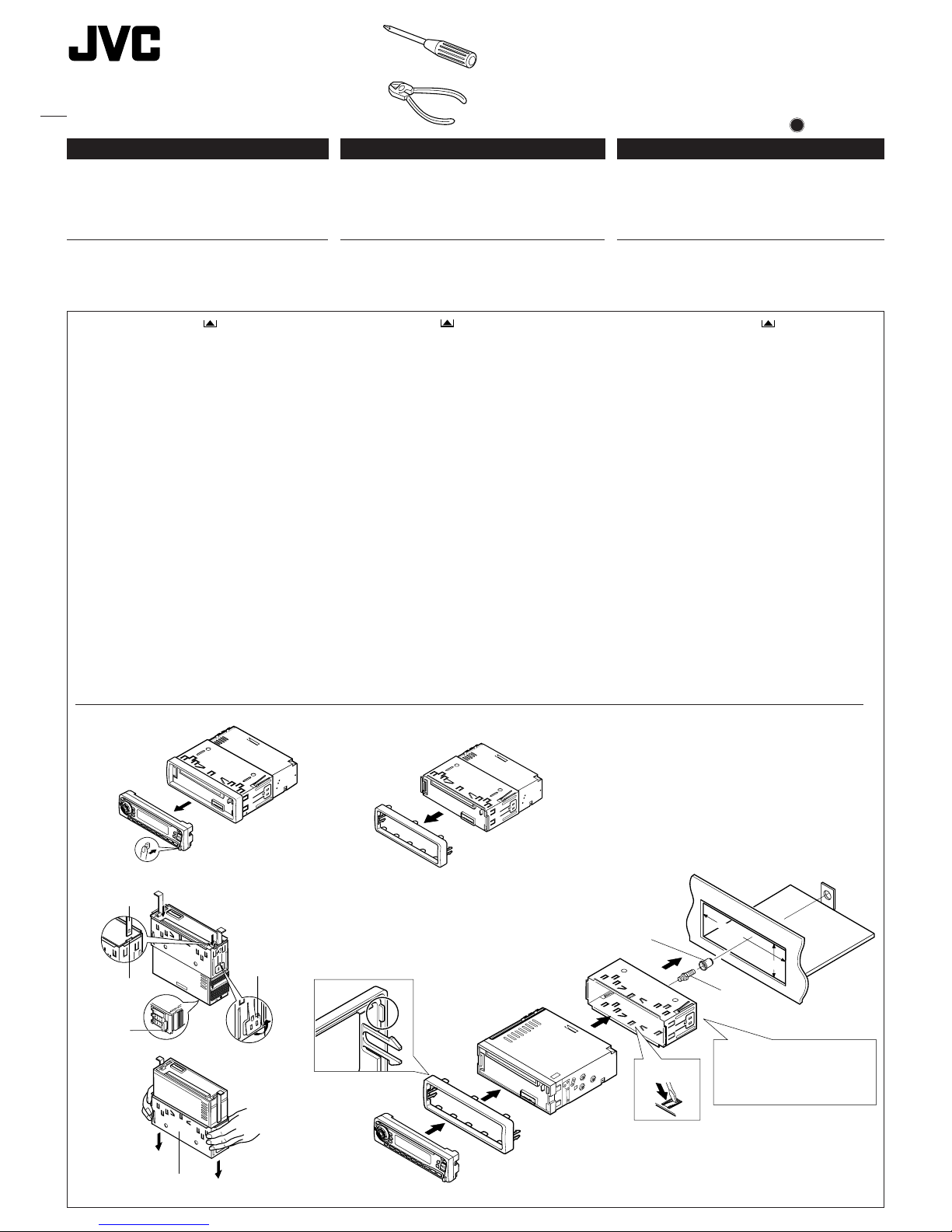
1
Before mounting: Press (Control Panel Release
button) to detach the control panel.
2
Remove the trim plate.
3
Remove the sleeve after disengaging the sleeve locks.
1 Stand the unit.
Note: When you stand the unit, be careful not to damage
the fuse on the rear.
2 Insert the 2 handles between the unit and the sleeve, as
illustrated, to disengage the sleeve locks.
3 Remove the sleeve.
Note: Be sure to keep the handles for future use after
installing the unit.
4
Install the sleeve into the dashboard.
* After the sleeve is correctly installed into the dashboard,
bend the appropriate tabs to hold the sleeve firmly in place,
as illustrated.
5
Fix the mounting bolt to the rear of the unit’s body and place
the rubber cushion over the end of the bolt.
6
Do the required electrical connections.
7
Slide the unit into the sleeve until it is locked.
8
Attach the trim plate so that the projection on the trim plate
is fixed to the left side of the unit.
9
Attach the control panel.
1
Vor dem Einbau: (Schalttafel-Freigabetaste) zum
Lösen der Schalttafel drücken.
2
Den Frontrahmen herausnehmen.
3
Die Halterung nach dem Entriegeln der Halterungensperren
abnehmen.
1 Das Gerät aufstellen.
Hinweis: Beim Aufstellen des Geräts darauf achten,
daß die Sicherung auf der Rückseite nicht beschädigt
wird.
2 Die beiden Griffe zwischen dem Gerät und der
Halterung wie abgebildet einstecken und die
Halterungensperren entriegeln.
3 Die Halterung entfernen.
Hinweis: Sicherstellen, daß die Griffe für künftigen
Gebrauch nach dem Einbau des Geräts aufbewahrt
werden.
4
Die Halterung im Armaturenbrett einbauen.
* Nach dem korrekten Einbau der Halterung im
Armaturenbrett, die entsprechenden Riegel umknicken,
um die Halterung an ihrem Platz zu sichern, siehe
Abbildung.
5
Die Befestigungsschraube an der Rückseite des
Gerätekörpers befestigen und das Ende der Schraube mit
einem Gummipuffer abdecken.
6
Nehmen Sie die erforderlichen elektrischen Anschlüsse vor.
7
Das Gerät in die Halterung schieben, bis es einrastet.
8
Befestigen Sie die Frontrahmen in der Form, daß der
Fortsatz der Frontrahmen auf der linken Seite des Geräts
befestigt wird.
9
Die Schalttafel anbringen.
1
Avant le montage:
Appuyer sur (touche de libération
du panneau de commande) pour détacher le panneau de
commande.
2
Retirer la plaque d’assemblage.
3
Libérer les verrous du manchon et retirer le manchon.
1
Poser l’appareil à la verticale.
Remarque:
Lorsque vous mettez l’appareil à la verticale,
faire attention de ne pas endommager le fusible situé
sur le fond.
2
Insérer les 2 poignées entre l’appareil et le manchon
comme indiqué pour désengagé les verrous de manchon.
3
Retirer le manchon.
Remarque:
S'assurer de garder les poignées pour une
utilisation ultérieur, après l'installation de l'appareil.
4
Installer le manchon dans le tableau de bord.
* Après installation correcte du manchon dans le tableau
de bord, plier les bonnes pattes pour maintenir fermement
le manchon en place, comme montré.
5
Monter le boulon de montage sur l’arrière du corps de
l’appareil puis passer l’amortisseur en caoutchouc sur
l’extrémité du boulon.
6
Réalisez les connexions électriques.
7
Faire glisser l’appareil dans le manchon jusqu’à ce qu’il soit
verrouillé.
8
Attachez la plaque d’assemblage de façon que la projection
de la plaque soit fixée sur le côté gauche de l’appareil.
9
Remonter le panneau de commande.
FRANÇAIS
•
Cet appareil est conçu pour fonctionner sur des sources de
courant continu de 12 volts à masse NEGATIVE.
INSTALLATION
(MONTAGE DANS LE TABLEAU DE BORD)
•
L’illustration suivante est un exemple d’installation typique.
Cependant, vous devez faire les ajustements correspondant à
votre voiture particulière. Si vous avez des questions ou avez
besoin d’information sur des kits d’installation, consulter votre
revendeur d’autoradios JVC ou une compagnie
d’approvisionnement.
DEUTSCH
• Dieses Gerät ist für einen Betrieb in elektrischen Anlagen mit
12 V Gleichstrom und (–) Erdung ausgelegt.
EINBAU
(IM ARMATURENBRETT)
• Die folgende Abbildung zeigt einen typischen Einbau. Dennoch
müssen Sie entsprechend Ihrem jeweiligen Auto Anpassungen
vornehmen. Bei irgendwelchen Fragen oder wenn Sie
Informationen hinsichtlich des Einbausatzes brauchen, wenden
Sie sich an ihren JVC Autoradiohändler oder ein Unternehmen
das diese Einbausätze vertreibt.
ENGLISH
• This unit is designed to operate on 12 volts DC, NEGATIVE
ground electrical systems.
INSTALLATION
(IN-DASH MOUNTING)
• The following illustration shows a typical installation. However,
you should make adjustments corresponding to your specific
car. If you have any questions or require information regarding
installation kits, consult your JVC IN-CAR ENTERTAINMENT
dealer or a company supplying kits.
Fuse
Sicherung
Fusible
1
Sleeve
Halterung
Manchon
Lock plate
Arretierplättchen
Plaque de verrouillage
Slot
Schlitz
Fente
Handle
Griffe
Poignée
3
184 mm
53 mm
Trim plate
Frontrahmen
Plaque d’assemblage
8
9
7
Sleeve
Halterung
Manchon
Rubber cushion
Gummipuffer
Amortisseur en caoutchouc
4
5
Dashboard
Armaturenbrett
Tableau de bord
4
*
6
2
Mounting bolt
Befestigungsschraube
Boulon de montage
See “ELECTRICAL CONNECTIONS.”
Siehe „ELEKTRISCHE ANSCHLÜSSE“.
Référez-vous “RACCORDEMENTS
ELECTRIQUES. ”
KD-SX878R
KD-S777R
Installation/Connection Manual
Einbau/Anschlußanleitung
Manuel d’installation/raccordement
FSUN3117-T211
[E]
Page 2
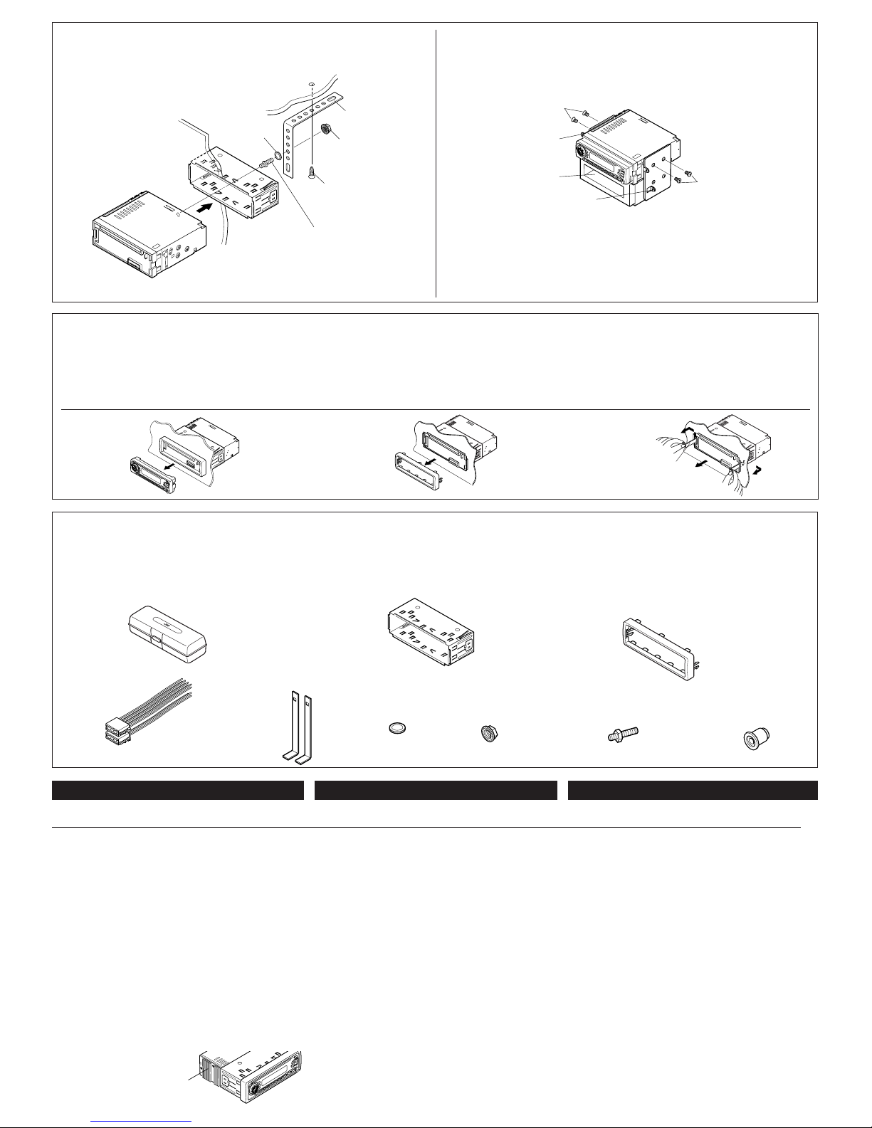
• When using the optional stay
• Beim Verwenden der Anker-Option
• Lors de l'utilisation du hauban en option
• When installing the unit without using the sleeve
• Beim Einbau des Geräts ohne Halterung
• Lors de l'installation de l’appareil scans utiliser de manchon
In a Toyota for example, first remove the car radio and install the unit in its place.
Zum Beispiel in einem Toyota zuerst das Autoradio ausbauen und dann das Gerät an seinem Platz einbauen.
Par exemple dans une Toyota, retirer d’abord l’autoradio et installer l’appareil à la place.
Parts list for installation and connection
The following parts are provided with this unit.
After checking them, please set them correctly.
Liste des pièces pour l’installation et
raccordement
Les pièces suivantes sont fournies avec cet appareil.
Après vérification, veuillez les placer correctement.
Teileliste für den Einbau und Anschluß
Die folgenden Teile werden zusammen mit diesem Gerät geliefert.
Nach ihrer Überprüfung, die Teile richtig einsetzen.
Power cord
Spannunsgversorgungskabel
Cordon d’alimentation
Rubber cushion
Gummipuffer
Amortisseur en caoutchouc
Mounting bolt (M5 x 20 mm)
Befestigungsschrauben (M5 x 20 mm)
Boulon de montage (M5 x 20 mm)
Removing the unit
• Before removing the unit, release the rear section.
1
Remove the control panel.
2
Remove the trim plate.
3
Insert the 2 handles into the slots, as shown. Then, while
gently pulling the handles away from each other, slide out the
unit. (Be sure to keep the handles after installing it.)
Ausbau des Geräts
• Vor dem Ausbau des Geräts den hinteren Teil freigeben.
1
Die Schalttafel abnehmen.
2
Den Frontrahmen abnehmen.
3
Die 2 Griffe in die Schlitze wie gezeigt stecken. Dann die Griffe
behutsam auseinander ziehen und das Gerät herausziehen.
(Die Griffe nach dem Einbau auf jeden Fall aufbewahren.)
Retrait de l’appareil
•
Avant de retirer l’appareil, libérer la section arrière.
1
Retirer le panneau de commande.
2
Retirer la plaque d’assemblage.
3
Introduire les deux poignées dans les fentes, comme montré.
Puis, tout en tirant doucement les poignées écartées, faire
glisser l’appareil pour le sortir.
(S'assurer de conserver les
poignées après l’installation de l’appareil.)
321
Note: When installing the unit on the mounting bracket, make sure to use the 6 mm-long screws. If
longer screws are used, they could damage the unit.
Hinweis: Beim Anbringen des Gerät an der Konsole sicherstellen, daß 6 mm lange Schrauben
verwendet werden. Werden längere Schrauben verwendet, können sie das Gerät beschädigen.
Remarque:
Lors de l'installation de l’appareil sur le support de montage, s’assurer d’utiliser des vis
d’une longueur de 6 mm. Si des vis plus longues sont utilisées, elles peuvent endommager l’appareil.
* Not included with this unit.
* Nicht Teil dieses Geräts.
*
Non fourni avec cet appareil.
Flat type screws (M5 x 6 mm)*
Senkkopfschrauben (M5 x 6 mm)*
Vis à tête plate (M5 x 6 mm)*
Bracket*
Konsole*
Support*
Flat type screws (M5 x 6 mm)*
Senkkopfschrauben (M5 x 6 mm)*
Vis à tête plate (M5 x 6 mm)*
Fire wall
Feuerwand
Cloison
Sleeve
Halterung
Manchon
Washer
Unterlegscheibe
Rondelle
Stay (option)
Anker (Option)
Hauban (en option)
Lock nut
Sicherungsmutter
Ecrou d’arrêt
Screw (option)
Schraube (Option)
Vis (en option)
Mounting bolt
Befestigungsschraube
Boulon de montage
Dashboard
Armaturenbrett
Tableau de bord
Pocket
Taschen
Poche
Bracket*
Konsole*
Support*
Handle
Griff
Poignée
Trim plate
Frontrahmen
Plaque d’assemblage
Sleeve
Halterung
Manchon
Hard case
Etui
Etui de transport
Handles
Griffe
Poignées
Washer (ø5)
Unterlegscheibe(ø5)
Rondelle (ø5)
Lock nut (M5)
Sicherungsmutter (M5)
Ecrou d’arrêt (M5)
ENGLISH
ELECTRICAL CONNECTIONS
T o prev ent short circuits, we recommend that you disconnect the battery’s
negative terminal and make all electrical connections before installing
the unit. If you are not sure ho w to install this unit correctly , hav e it installed
by a qualified technician.
Note:
This unit is designed to operate on 12 volts DC, NEGATIVE ground
electrical systems. If y our vehicle does not ha v e this system, a voltage
inverter is required, which can be purchased at JVC IN-CAR
ENTERTAINMENT dealers.
• Replace the fuse with one of the specified rating. If the fuse blows
frequently, consult your JVC IN-CAR ENTERTAINMENT dealer.
• If noise is a problem...
This unit incorporates a noise filter in the power circuit. How ever, with
some vehicles, clicking or other unwanted noise may occur. If this
happens, connect the unit’s rear ground terminal (see connection
diagram) to the car’s chassis using shorter and thicker cords, such as
copper braiding or gauge wire. If noise still persists, consult your JVC
IN-CAR ENTERTAINMENT dealer.
• Maximum input of the speakers should be more than 40 watts at the
rear and 40 watts at the front, with an impedance of 4 to 8 ohms.
• Be sure to ground this unit to the car’s chassis.
• The heat sink becomes very hot after use. Be careful not to touch it
when removing this unit.
FRANÇAIS
RACCORDEMENTS ELECTRIQUES
Pour éviter tout court-circuit, nous vous recommandons de débrancher
la borne négative de la batterie et d’effectuer tous les raccordements
électriques avant d’installer l’appareil. Si l'on n’est pas sûr de pouvoir
installer correctement cet appareil, le faire installer par un technicien
qualifié.
Remarque:
Cet appareil est conçu pour fonctionner sur des sources de courant
continu de
12 volts à masse NEGATIVE
. Si votre véhicule n’offre pas
ce type d’alimentation, il vous faut un conv ertisseur de tension, que vous
pouvez acheter chez un revendeur d’autoradios JVC.
•
Remplacer le fusible par un de la valeur précisée. Si le fusible saute
souvent, consulter votre revendeur d’autoradios JVC.
•
Si le bruit est un problème...
Cet appareil incorpore un filtre de bruit dans le circuit d’alimentation.
Cependant, avec certains véhicules, quelques claquements ou autres
bruits non désirés risquent de se produire. Si cela arrive, raccorder la
borne de masse arrière
de l’appareil au châssis de la voiture (voir le
schéma de raccordement) en utiliscant des cordons les plus gros et
les plus courts possibles telle qu'une barre de cuivre ou une tresse. Si
le bruit persiste, consulter votre revendeur d’autoradios JVC.
•
La puisscance admissible des haut-parleurs doit être supérieure à 40
watts à l’arrière et à 40 watts l’avant, avec une impédance de
4 à 8
ohms
.
• S'assurer de raccorder la mise à la masse de cet appareil au
châssis de la voiture.
•
Le radiateur devient très chaud après usage. Faire attention de ne
pas le toucher en retirant cet appareil.
DEUTSCH
ELEKTRISCHE ANSCHLÜSSE
Zur Vermeidung von Kurzschlüssen empfehlen wir, daß Sie den
negativen Batterieanschluß abtrennen und alle elektrischen
Anschlüsse herstellen, bevor das Gerät eingebaut wird. Sind Sie sich
über den richtigen Einbau des Geräts nicht sicher, lassen Sie es von
einem qualifizierten Techniker einbauen.
Hinweis:
Dieses Gerät ist für den Betrieb in elektrischen Anlagen mit 12 V
Gleichstrom und (–) Erdung ausgelegt. Verfügt Ihr Fahrzeug nicht
über diese Anlage, ist ein Spannungsinverter erforderlich, der bei
JVC Autoradiohändler erworben werden kann.
• Die Sicherung mit einer der entsprechenden Nennleistung ersetzen.
Brennt die Sicherung häufig durch, wenden Sie sich an ihren JVC
Autoradiohändler.
• Sind Störgeräusche ein Problem...
Dieses Gerät enthält ein Störfilter im Stromkreis. Bei manchen
Fahrzeugen kann jedoch ein Klicken oder andere unerwünschte
Störgeräusche auftreten. Sollte das der Fall sein, die hintere
Erdungscanschlußklemme (siehe Schaltplan) des Geräts am
Fahrwerk des Fahrzeugs anschließen, dabei kürzere und dickere
Kabel wie beispielsweise Kupfergeflechtdraht oder Stahldraht
verwenden. Bleibt Störgeräusch bestehen, wenden Sie sich an Ihren
JVC Autoradiohändler.
• Maximale Eingangsleistung der Lautsprecher muß höher als 40 W
hinten und 40 W vorne sein, mit einer Impedanz von 4 bis 8 Ohm.
• Sicherstellen, daß das Gerät am Fahrwerk geerdet wird.
• Das Abstrahlblech wird nach dem Gebrauch sehr heiß. Beim
Ausbau des Geräts darauf achten, das Abstrahlblech nicht zu
berühren.
Heat sink
Abstrahlblech
Dissipateur de chaleur
Page 3

Avant de commencer la connexion:
vérifiez attentivement le
câblage du véhicule. Une connexion incorrecte peut endommager
sérieusement l’appareil.
1
Connectez les fils de couleur du cordon d’alimentation à la
batterie de la voiture, aux enceintes et à l’antenne automatique
(s’il y en a une) dans l’ordre suivant.
1
Noir: a la masse
2
Jaune: a la batterie de la voiture (12V constant)
3
Rouge: à la prise accessoire
4
Autres: aux enceintes
5
Bleu à bandes blanches: à l’antenne automatique (200
mA max.)
6
Marron: à un système de téléphone cellulaire (Pour les
détails, se référer aux instructions du téléphone cellulaire.)
2
Connectez le cordon d’antenne.
3
Finalement, connectez le faisceau de fils à l’appareil.
Remarque:
Si votre véhicule ne possède pas de borne
accessoire, déplacez le fusible de la position de fusible 1 (position
originale) à la position de fusible 2 et connectez le fil rouge (A7)
à la borne positive (+) de la batterie.
• Le fil jaune (A4) n’est pas utilisé dans ce cas.
A Typical Connections / Typische Anschlüsse / Raccordements typiques
Before connecting: Check the wiring in the vehicle carefully.
Incorrect connection may cause serious damage to this unit.
1
Connect the colored leads of the power cord to the car battery,
speakers and power aerial (if any) in the following sequence.
1 Black: ground
2 Yellow: to car battery (constant 12V)
3 Red: to an accessory terminal
4 Others: to speakers
5 Blue with white stripe: to power aerial (200mA max.)
6 Brown: to cellular phone system (For details, refer to the
instructions of the cellular phone.)
2
Connect the aerial cord.
3
Finally connect the wiring harness to the unit.
Note: If your vehicle does not hav e any accessory terminal, move
the fuse from the fuse position 1 (initial position) to fuse position
2, and connect the red lead (A7) to the positive (+) battery terminal.
• The yellow lead (A4) is not used in this case.
Vor dem Anschließen: Die Verdrahtung im Fahr zeug sorgfältig
überprüfen. Falsche Anschlüsse können ernsthafte Schäden am
Gerät hervorrufen.
1
Die farbigen Leitungen des Spannunsgversorgungskabels an
der Autobatterie, den Lautsprechern und dem Motorantenne
(sofern vorhanden) in folgender Reihenfolge anschließen.
1 Schwarz: Erdung
2 Gelb: an autobatterie (konstant 12 V)
3 Rot: an Zubehöranschlußklemme
4 Andere: an Lautsprecher
5 Blau mit weißem Streifen: an Motorantenne (max. 200 mA)
6 Braun: an Mobiltelefon (Weitere informationen entnehmen
Sie bitte der Bedienungscanleitung des Mobiltelefons.)
2
Das Antennenkabel anschließen.
3
Die Kabelbäume am Gerät anschließen.
Hinweis: Verfügt Ihr Fahrzeug nicht über eine
Zubehöranschlußklemme, die Sicherung von der 1.
Sicherungsposition (Erstposition) in die 2. Sicherungsposition
versetzen, die rote Leitung (A7) an der (+)
Batterieanschlußklemme anschließen.
• Die gelbe Leitung (A4) wird in diesem Fall nicht verwendet.
B110B3 B5 B7
B2 B4 B6 B8
A5 A7
A2 A4 A8
2
3
1
5
6
1
2
3
4
A8
A4
A7
A5
A2
B6 B5 B4 B3 B8 B7 B2 B1
B1 B3 B5 B7
B2 B4 B6 B8
A5 A7
A2 A4 A6 A8
Purple
Lila
Violet
Left speaker (rear)
Linker Lautsprecher (hinten)
Haut-parleur gauche (arrière)
White with black stripe
Weiß mit schwarzem
Streifen
Blanc avec bande noire
Gray with black stripe
Grau mit schwarzem
Streifen
Gris avec bande noire
White
Weiß
Blanc
Gray
Grau
Gris
Green with black stripe
Grün mit schwarzem
Streifen
Vert avec bande noire
Green
Grün
Ver t
Purple with black stripe
Lila mit schwarzem Streifen
Violet avec bande noire
Right speaker (rear)
Rechter Lautsprecher
(hinten)
Haut-parleur droit (arrière)
Right speaker (front)
Rechter Lautsprecher (vorne)
Haut-parleur droit (avant)
Left speaker (front)
Linker Lautsprecher (vorne)
Haut-parleur gauche (avant)
*
*
To metallic body or chassis of the car
Zur metallenen Karosserie oder zum Fahrwerk des
Autos
Vers corps métallique ou châssis de la voiture
To a live terminal in the fuse block connecting to the car battery
(bypassing the ignition swich)
Zur einer stromführenden Anschlußklemme im Sicherungsblock zum
Anschließen an die Autobatterie (Umgehen des Zündschalters)
A une borne sous tension du porte-fusible connectée à la batterie de la
voiture (en dérivant l’interrupteur d’allumage)
Aerial terminal
Antennenanschlußklemme
Borne de l’antenne
Black
Schwarz
Noir
To power aerial if any
Zur Motorantenne, sofern vorhanden
Vers borne d’antenne automatique s'il y en a une
To an accessory terminal in the fuse block
Zur einer Zubehöranschlußklemme im Sicherungsblock
Vers borne accessoire du porte-fusible
Fuse block
Sicherungsblock
Porte-fusible
Brown / Braun /
Marron
*
Not included with this unit.
Wird nicht mit Gerät mitgeliefert.
Non fourni avec cet appareil.
Ignition switch
Zündschalter
Interrupteur d’allumage
Fuse position 2
2. Sicherungsposition
Position de fusible 2
Fuse position 1
1. Sicherungsposition
Position de fusible 1
*1: Before checking the operation of this unit prior to
installation, this lead must be connected, otherwise
power cannot be turned on.
*1: Vor der Überprüfung der Funktionsfähigkeit des Geräts
vor dem Einbau, muß diese Leitung angeschlossen
werden, da sonst die Stromversorgung nicht
eingeschaltet werden kann.
*1: Pour vérifier le fonctionnement de cet appareil avant
installation, ce fil doit être raccordé, sinon l’appareil
ne peut pas être mis sous tension.
To aerial
Zur Antenne
A l'antenne
Rear ground terminal
Hintere
Erdungscanschlußklemme
Borne arrière de masse
Line out
(see diagram B )
Ausgang (line-out)
(siehe schaltplan B )
Sortie de ligne
(voir le diagramme B )
When connecting a CD changer, we recommend to use one of the CH-X series CD changers.
• If your CD changer is one of the KD-MK series, you need an optional cord (KS-U15K).
You can also use an e xternal component such as a portable MD player b y connecting the Line Input Adaptor
KS-U57 (not supplied). (See diagram B .)
Wenn Sie einen CD-Wechsler anschließen möchten, empfiehlt es sich, einen CD-Wechsler der Modellreihe
CH-X zu verwenden.
• Wenn Ihr CD-Wechsler zur Modellreihe KD-MK gehören, benötigen Sie ein anderes Kabel (KS-U15K).
Sie können auch eine externe Komponente, z.B. einen tragbaren MD-Spieler, verwenden, wenn Sie den
(nicht zum Lieferumfang gehörenden) Line-Eingangsadapter KS-U57 anschließen (siehe Diagramm B ).
Nous recommandons que vous connectiez un changeur de CD de la série CH-X.
• Si votre changeur de CD appartient à la série KD-MK, vous avez besoin d’un cordon optionnel (KSU15K).
Vous pouvez aussi utiliser un appareil e xtérieur tel qu’un lecteur de MD en connectant l’adaptateur d’entrée
de ligne KS-U57 (non fourni) (voir le diagramme B ).
To cellular phone system
Zur Moblitelephon
à un système de téléphone cellulaire
Red
Rot
Rouge
Y ellow*
1
Gelb*
1
Jaune*
1
Blue with white stripe
Blau mit weißem Streifen
Bleu avec bande blanche
PRECAUTIONS on power supply and speaker
connections:
• DO NOT connect the speaker leads of the power cord to
the car battery; otherwise, the unit will be seriously
damaged.
• Connect the black lead (ground), yellow lead (to car battery,
constant 12V), and red lead (to an accessory terminal) correctly.
• BEFORE connecting the speaker leads of the power cord to
the speakers, check the speaker wiring in your car.
– If the speaker wiring in your car is as illustrated in Fig. 1
and Fig. 2 below, DO NOT connect the unit using that original
speaker wiring. If you do , the unit will be seriously damaged.
Redo the speaker wiring so that you can connect the unit to
the speakers as illustrated in Fig. 3.
– If the speaker wiring in your car is as illustrated in Fig. 3,
you can connect the unit using the original speaker wiring in
your car.
– If you are not sure of the speaker wiring of your car, consult
your car dealer.
Fig. 2Fig. 1 Fig. 3
L
R
+
-
+
-
+
-
+
-
L
R
+
-
+
-
+
-
+
-
L
R
+
-
+
-
+
-
+
-
VORSICHTSMASSREGELN beim Anschließen der
Stromversorgung und Lautsprecher:
• Die Lautsprecherleitungen des Netzkabels NICHT an der
Autobatterie anschließen, da sonst das Gerät schwer
beschädigt wird.
• Die schwarze Leitung (Erdung), die gelbe Leitung (zur
Autobatterie, konstant 12 V) und die rote Leitung (zur
Zubehöranschlußklemme) richtig anschließen.
• VOR dem Anschließen der Lautsprecherleitungen des
Spannunsgversorgungskabels an die Lautsprecher, die
Lautsprecherverdrahtung in Ihrem Auto überprüfen.
– Ist die Lautsprecherverdrahtung wie unten in “Fig. 1”
und “Fig. 2” abgebildet, das Gerät NICHT mit der
Originalverdrahtung der Lautsprecher anschließen, da
sonst das Gerät schwer beschädigt wird.
Die Lautsprecherverdrahtung erneuern, so daß Sie das Gerät
an den Lautsprechern wie in “Fig. 3” abgebildet anschließen
können.
– Ist die Lautsprecherverdrahtung in Ihrem Auto wie in “Fig.
3” abgebildet, können Sie das Gerät mit der
Originalverdrahtung der Lautsprecher in Ihrem Auto
anschließen.
– Sind Sie sich über die Lautsprecherverdrahtung in Ihrem Auto
nicht sicher, wenden Sie sich an Ihren Autohändler.
PRECAUTIONS sur l’alimentation et la
connexion des enceintes:
• NE CONNECTEZ PAS les fils d’enceintes du cordon
d’alimentation à la batterie; sinon, l’appareil serait
sérieusement endommagé.
•
Connectez correctement le fil noir (a la masse), le fil jaune (a
la batterie de la voiture,12V constant) et le fil rouge (à la prise
accessoire).
•
AVANT de connecter les fils d’enceintes du cordon
d’alimentation aux enceintes, vérifiez le câblage des enceintes
de votre voiture.
–
Si le câblage des enceintes de votre voiture est réalisé
comme montré sur la Fig. 1 ou Fig. 2 ci-dessous,
NE
CONNECTEZ PAS l’appareil en utiliscant ce câb lage original
d’enceintes. Si vous le faites, l’appareil sera sér ieusement
endommagé.
Recommencez le câblage des enceintes de façon que vous
puissiez connecter l’appareil aux enceintes comme montré
sur la Fig. 3.
–
Si le câblage des enceintes de votre voiture est comme
montré sur la Fig. 3,
vous pouvez connecter l’appareil en
utiliscant ce câblage original d’enceintes pour votre voiture.
– Si vous n’êtes pas sûrs du câblage d’enceintes de votre
voiture, consulter le concessionnaire de votre voiture.
10A fuse
10A Sicherung
Fusible 10A
ONLY FOR KD-SX878R
NUR FÜR KD-SX878R
SEULEMENT POUR LE KD-SX878R
CD changer or another external component
CD-Wechsler oder eine andere externe
Komponente
Changeur CD ou autre appareil extérieur
Page 4

CAUTION / VORSICHT/ PRECAUTION:
• To prevent short-circuit, cover the terminals of the UNUSED leads with
insulating tape.
• Zur Vermeidung eines Kurzschlusses die Anschlußklemmen der NICHT
VERWENDETEN Leitungen mit Isolierklebeband umwickeln.
• Pour éviter les court-circuits, couvrir les bornes des fils qui ne sont
PAS utilisés avec de la bande isolante.
Connecting the leads / Anschließen der Leitungen / Raccordement des fils
FEHLERSUCHE
• Die Sicherung brennt durch.
* Sind die roten und schwarzen Leitungen richtig angeschlossen?
• Stromversorgung kann nicht eingeschaltet werden.
* Ist die gelbe Leitung angeschlossen?
• Kein Ton aus den Lautsprechern.
* Ist die Lautsprecherausgangsleitung kurzgeschlossen?
• Ton verzerrt.
* Ist die Lautsprecherausgangsleitung geerdet?
* Sind die (–) Anschlußklemmen der linken und rechten
Lautsprecher zusammen geerdet?
• Gerät wird heiß.
* Ist die Lautsprecherausgangsleitung geerdet?
* Sind die (–) Anschlußklemmen der linken und rechten
Lautsprecher zusammen geerdet?
TROUBLESHOOTING
• The fuse blows.
* Are the red and black leads connected correctly?
• Power cannot be turned on.
* Is the yellow lead connected?
• No sound from the speakers.
* Is the speaker output lead short-circuited?
• Sound is distorted.
* Is the speaker output lead grounded?
* Are the “–” terminals of L and R speakers grounded in common?
• Unit becomes hot.
* Is the speaker output lead grounded?
* Are the “–” terminals of L and R speakers grounded in common?
EN CAS DE DIFFICULTÉS
• Le fusible saute.
*
Les fils rouge et noir sont-ils racordés correctement?
• L’appareil ne peut pas être mise sous tension.
*
Le fil jaune est-elle raccordée?
• Pas de son des haut-parleurs.
*
Le fil de sortie de haut-parleur est-il court-circuité?
• Le son est déformé.
*
Le fil de sortie de haut-parleur est-il à la masse?
*
Les bornes “–” des haut-parleurs gauche et droit sont-elles mises
ensemble à la masse?
• L’appareil devient chaud.
*
Le fil de sortie de haut-parleur est-il à la masse?
*
Les bornes “–” des haut-parleurs gauche et droit sont-elles mises
ensemble à la masse?
Twist the core wires when connecting.
Die Kerndrähte beim Anschließen
verdrehen.
Torsader les âmes des fils en les
raccordant.
Solder the core wires to connect them securely.
Die Kerndrähte anlöten, um sie fest anzuschließen.
Souder les âmes desfils pour les raccorder entre eux
de façon sûre.
INPUT
R
L
R
L
LINE OUT
REAR
L
R
L
R
L
R
B Connections Adding Other Equipment / Anschlüsse zum Hinzufügen von anderer Ausrüstung / Raccordement pour ajouter d’autres appareils
Amplifier / Verstärker / Amplificateur
You can connect an amplifier and other equipment to upgrade
your car stereo system.
• Connect the remote lead (blue with white stripe) to the remote
lead of the other equipment so that it can be controlled through
this unit.
• For amplifier only:
– Connect this unit’s line-out terminals to the amplifier’s line-in
terminals.
– Disconnect the speakers from this unit, connect them
to the amplifier. Leave the speaker leads of this unit
unused. (Cover the terminals of these un used leads with
insulating tape, as illustrated above.)
Vous pouvez connecter un amplificateur ou autre appareil pour
améliorer votre système autoradio.
•
Connectez le fil de commande à distance (bleu avec bande
blanche) au fil de commande à distance de l’autre appareil de
façon qu’il puisse être commandé via cet appareil.
•
Pour l'amplificateur seulement:
– Raccorder les bornes de sor tie ligne de cet appareil aux
bornes d’entrée ligne de l’amplificateur.
– Déconnectez les enceintes de cet appareil et connectez-
les à l’amplificateur. Laissez les fils d’enceintes de cet
appareil inutilisés. (Recouvrir les extrémités de ces fils
inutilisés avec de la bande isolante comme montré cidessus.)
Sie können einen Verstärker oder ein anderes Gerät anschließen,
um Ihre Autostereoanlage zu erweitern.
• Schließen Sie das Fernbedienungskabel (blau mit weißem
Streifen) an das Fernbedienungskabel des anderen Geräts an,
so daß es über dieses Gerät gesteuert werden kann.
• Nur für den Verstärker:
– Die Anschlußklemmen am Ausgang dieses Gerät an den
Anschlußklemmen des Eingangs des Verstärkers
anschließen.
– Die Lautsprecher von diesem Gerät abtrennen und am
Verstärker anschließen. Die Lautsprecherleitungen dieses
Geräts unbenutzt lassen. (Die Anschlußklemmen dieser
nicht verwendeten Leitungen mit Isolierband umwickeln,
siehe Abb. oben.)
JVC Amplifier
JVC Verstärker
JVC Amplificateur
Signal cord (not supplied with this unit)
Einzelleitung (nicht mit diesem Gerät mitgeliefert)
Cordon de signal (non fourni avec cet appareil)
Rear speakers
Hintere Lautsprecher
Haut-parleur arrière
Blue with white stripe
Blau mit weißem Streifen
Bleu avec bande blanche
Y-connector (not supplied with this unit)
Y-Anschluß (nicht mitgeliefert)
Connecteur Y (non fourni avec cet appareil)
KD-SX878R
KD-S777R
Front speakers
Vordere Lautsprecher
Haut-parleur avant
Remote lead (Blue with white stripe)
Fernbedienungsleitung (Blau mit weißem Streifen)
Fil d'alimentation à distance (Bleu avec bande blanche)
To power aerial if any
Zur Motorantenne, sofern vorhanden
Vers l’antenne automatique, s’il y en a une
CD changer and DAB tuner / CD-Wechsler und DAB-Tuner / Changeur CD et tuner DAB
Y ou can connect a JVC CD changer and/or a JVC DAB (Digital
Audio Broadcasting) tuner.
• For their connections, refer to the instructions supplied with
them.
Sie können einen CD-Wechsler und/oder einen DAB-Tuner (Tuner
für digitalen Rundfunk) von JVC anschließen.
• Weitere Informationen über den Anschluß können Sie der
Bedienungscanleitung entnehmen, die dem jeweiligen Gerät
beiliegt.
Vous pouvez connecter un changeur CD JVC et/ou un tuner
DAB (Digital Audio Broadcast) JVC.
•
Pour leurs connexions , référez-vous aux modes d’emploi qui
les accompagnent.
Connecting cord supplied with your DAB tuner
Verbindungskabel, das zum Lieferumfang des DABTuners gehört
Cordon de connexion fourni avec votre tuner DAB
Connecting cord supplied with your CD changer
Verbindungskabel, das zum Lieferumfang des CDWechsler gehört
Cordon de connexion fourni avec v otre changeur CD
ONLY FOR KD-SX878R
SEULEMENT POUR LE KD-SX878RNUR FÜR KD-SX878R
JVC DAB tuner
DAB-Tuner von JVC
Tuner DAB JVC
JVC CD changer
CD-Wechsler von JVC
Changeur CD JVC
KD-SX878R
CAUTION / VORSICHT / PRECAUTION:
• To prevent internal heat buildup inside this unit, place this unit UNDER the other equipment.
• Zur Vermeidung eines Hitzestaus in diesem Gerät, dieses Gerät UNTER die andere
Geräteansrüstung stellen.
• Pour éviter un échauffement interne de cet appareil, placez-le SOUS l'autre appareil.
R
L
LINE OUT
REAR
L
R
L
R
L
R
L
R
KD-SX878R
External component / Externe Komponente / Appareil extérieur
ONLY FOR KD-SX878R SEULEMENT POUR LE KD-SX878RNUR FÜR KD-SX878R
External component
Externe Komponente
Appareil extérieur
• You can connect both components in series as illustrated above.
• Es ist möglich, beide Komponenten in einer Serienschaltung entsprechend
der obigen Darstellung anzuschließen.
• Vous pouvez connecter les deux appareils en série comme montré ci-dessus .
or
oder
ou
JVC DAB tuner
DAB-Tuner von JVC
Tuner DAB JVC
JVC CD changer
CD-Wechsler von JVC
Changeur CD JVC
KD-SX878R
Connecting cord supplied with your DAB tuner or CD changer
Verbindungskabel, das zum Lieferumfang des DAB-Tuners oder CDWechslers gehört
Cordon de connexion fourni avec votre tuner DAB ou changeur CD
CAUTION / VORSICHT / PRECAUTION:
• Before connecting the CD changer and/or the DAB tuner, make sure that the unit is turned off.
• Bevor Sie den CD-Wechsler und/oder den DAB-Tuner anschließen, vergewissern Sie sich,
daß das Gerät ausgeschaltet ist.
• Avant de connecter le changeur CD et/ou le tuner DAB, s’assurer que l’unité est éteinte.
CD changer jack
Buchse für CD-Wechsler
Prise du changeur CD
Line Input Adaptor KS-U57 (not supplied with this unit)
Line-Eingangsadapter KS-U57 (nicht mit diesem Gerät
mitgeliefert)
Adaptateur d’entrée de ligne KS-U57 (non fourni avec cet
appareil)
Signal cord (not supplied with this unit)
Einzelleitung (nicht mit diesem Gerät mitgeliefert)
Cordon de signal (non fourni avec cet appareil)
 Loading...