

Page 1

INPUT CARD FOR A JVC MONITOR
BEDIENUNGSANLEITUNG: EINGANGSKARTE FÜR JVC MONITORE
MANUEL D’INSTRUCTIONS:
ISTRUZIONI: SCHEDA DI INGRESSO PER MONITOR JVC
MANUAL DE INSTRUCCIONES:TARJETA DE ENTRADA PARA UN MONITOR JVC
CARTE D’ENTRÉE POUR MONITEURS JVC
МОДУЛЬ ВХОДОВ ДЛЯ МОНИТОРА JVC
ENGLISH
DEUTSCH
FRANÇAIS
ITALIANO
IF-CF01CMG
COMPONENT/RGB INPUT CARD
IF-CF01RBG
COMPONENT/RGB ACTIVE THROUGH CARD
IF-CF21HDG
HD/SD SDI INPUT CARD
INSTRUCTIONS
ESPAÑOL
LCT1973-001A
Page 2
INPUT CARD FOR A JVC MONITOR
ENGLISH
IF-CF01CMG
COMPONENT/RGB INPUT CARD
IF-CF01RBG
COMPONENT/RGB ACTIVE THROUGH CARD
IF-CF21HDG
HD/SD SDI INPUT CARD
INSTRUCTIONS
1
Page 3
Thank you for purchasing this JVC Input Card. In order to take full advantage of the
card’s capabilities, please read and follow all instructions carefully before installing
and using the card. Retain this booklet for future reference.
Precautions
Before installing this Input Card in your monitor, please read the Safety
Precautions included in your monitor’s user manual.
FCC NOTICE
7 For IF-CF01CMG and IF-CF01RBG
CAUTION: Changes or modifications not approved by JVC could void the user ’s authority to
operate the equipment.
NOTE: This equipment has been tested and found to comply with the limits for a Class B digital
device, pursuant to Part 15 of the FCC Rules. These limits are designed to provide reasonable
protection against harmful interference in a residential installation. This equipment generates, uses
and can radiate radio frequency energy and, if not installed and used in accordance with the
instructions, may cause harmful interference to radio communications. However, there is no
guarantee that interference will not occur in a particular installation. If this equipment does cause
harmful interference to radio or television reception, which can be determined by turning the
equipment off and on, the user is encouraged to try to correct the interference by one or more of
the following measures:
– Reorient or relocate the receiving antenna.
– Increase the separation between the equipment and receiver.
– Connect the equipment into an outlet on a circuit different from that to which the receiver is
connected.
– Consult the dealer or an experienced radio/TV technician for help.
7 For IF-CF21HDG
CAUTION: Changes or modifications not approved by JVC could void the user’s authority to
operate the equipment.
NOTE: This equipment has been tested and found to comply with the limits for a Class A digital
device, pursuant to Part 15 of the FCC Rules. These limits are designed to provide reasonable
protection against harmful interference when the equipment is operated in a commercial
environment. This equipment generates, uses, and can radiate radio frequency energy and, if not
installed and used in accordance with the instruction manual, may cause harmful interference to
radio communications. Operation of this equipment in a residential area is likely to cause harmful
interference in which case the user will be required to correct the interference at his own expense.
EUROPE EMC STANDARD NOTICE (For IF-CF21HDG only)
Warning: This is a class A product. In a domestic environment this product may cause radio
interference in which case the user may be required to take adequate measure.
EMC Supplement (For IF-CF21HDG only)
This equipment is in conformity with the provisions and protection requirements of the
corresponding European Directives. This equipment is designed for professional video appliances
and can be used in the following environments:
• Controlled EMC environment (for example purpose built broadcasting or recording studio), and
the rural outdoors environment (far away from railways, transmitters, overhead power lines, etc.)
These input cards are only for use with specific monitors.
Consult your dealer for the compatible monitors.
2
Page 4
Information for Users on Disposal of Old Equipment
[European Union]
This symbol indicates that the electrical and electronic equipment should not be
disposed as general household waste at its end-of-life. Instead, the product should
be handed over to the applicable collection point for the recycling of electrical and
electronic equipment for proper treatment, recovery and recycling in accordance
Attention:
This symbol is
only valid in the
European
Union.
with your national legislation.
By disposing of this product correctly, you will help to conserve natural resources
and will help prevent potential negative effects on the environment and human
health which could otherwise be caused by inappropriate waste handling of this
product. For more information about collection point and recycling of this product,
please contact your local municipal office, your household waste disposal service
or the shop where you purchased the product.
Penalties may be applicable for incorrect disposal of this waste, in accordance with
national legislation.
(Business users)
If you wish to dispose of this product, please visit our web page
www.jvc-europe.com to obtain information about the take-back of the product.
[Other Countries outside the European Union]
If you wish to dispose of this product, please do so in accordance with applicable
national legislation or other rules in your country for the treatment of old electrical
and electronic equipment.
ENGLISH
3
Page 5
Before Installation
7 Accessaries
• Label (x 1): For placing to the rear panel and the remote control of the monitor after installing
the Input Card.
• Slot cover* (x 1): For covering the blank slot.
* Not supplied for IF-CF01RBG
7 Preparation
•Wear gloves to protect your hands from metal parts on the Input Card’s board.
•You will need a 6 mm Phillips screwdriver.
•Turn off the monitor’s main power and unplug the power cable from the AC outlet.
• Place the monitor with its LCD panel side down on a soft cloth so as not to damage the LCD panel.
7 Cautions
• Do not touch the terminals or board pattern of the Input Card to keep it from being damaged by
static electricity.
• Do not damage the Input Card’s connection terminal.
• Do not put anything into the Input Card’s holes or intakes.
• Do not force the Input Card into the monitor’s slot.
• Attach the slot cover on the monitor’s slot in which no Input Card is installed.
• Attach the Input Card before mounting the monitor on the stand or wall mounting unit.
Installation
7 Installation procedure
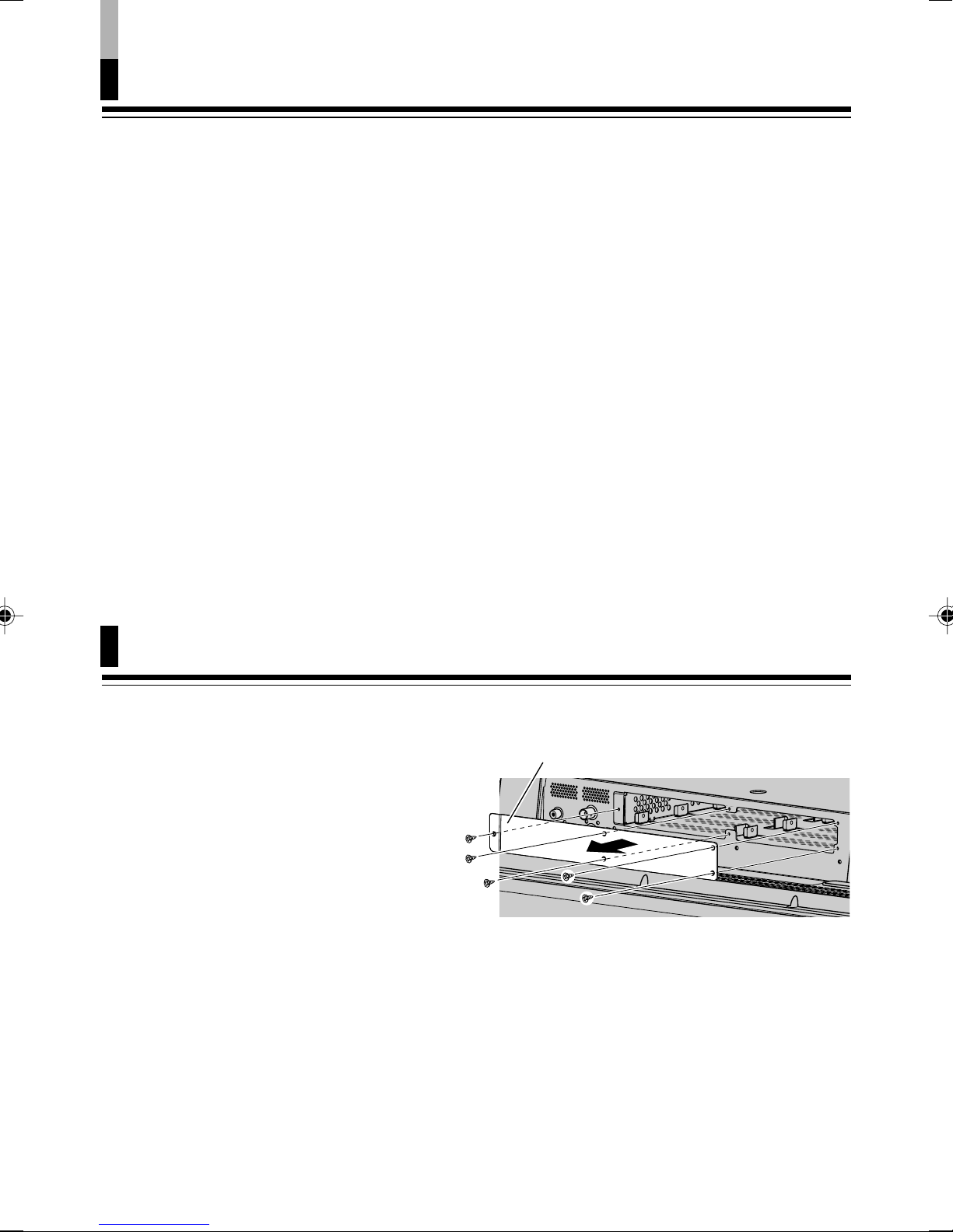
1.
Remove the slot cover from the
slot on the bottom side of the
monitor.
Slot cover
The monitor in the illustration is GM-H40L1G.
4
Page 6

Installation (continued)
2.
Insert the Input Card into the slot,
fitting into the guides inside the
slot, so that its panel touches the
bottom of the monitor.
For IF-CF01CMG and IF-CF21HDG:
You can install the Input Card(s) into
either left or right slot. When installing,
follow the procedure below.
When installing two Input Cards:
•
Install either of Input Cards into the left
slot first.
•
When installing only one Input Card:
You need to attach the supplied slot
cover to the blank slot.
Install either Input Card or the supplied
slot cover into the left slot first as
illustrated on the right. (The Input Card
in the illustration is IF-CF21HDG.)
Ex.: When installing only one Input Card
1, then 2.
Insert
Guide
Panel
Slot cover (supplied)
or
Slot cover (supplied)
Guide
ENGLISH
3.
Secure the Input Card by using the
screws removed in Step 1 on the
previous page.
After installation
• Place the supplied labels on the rear panel and the
remote control of the monitor as illustrated on the right.
– On the rear panel: Place the label on the name of the
slot into which you have installed the Input Card.
– On the remote control: Place the label on the printing
of the corresponding input select buttons.
• Make sure the Input Card is correctly recognized by
“INPUT CONFIGURATION” (“INPUT C” – “INPUT F”) on
the main menu of the monitor.
Panel
On the rear panel
On the remote control
5
Page 7

Controls and Features
7 IF-CF01CMG (Component/RGB Input Card)
Front view
Label
Rear view
1 Audio signal input terminal
Accepts analog audio signals.
NOTE:
• This terminal cannot be used for both RGB and component signals at the same time.
2 Component/RGB signal input terminals
Accepts component (color difference) or RGB signals.
Select input by using the button on the monitor.
Select component signal: INPUT C (SLOT-1)/E (SLOT-2)
Select RGB signal: INPUT D (SLOT-1)/F (SLOT-2)
3 Synchronized signal input terminals
When RGB signal is selected, accepts the vertical, horizontal or composite
synchronized signals.
When using these terminals, “SYNC TERM.” can be switched between “HIGH” and
“LOW.” Refer to your monitor instruction manual for more information.
4 Label (see page 5)
1 On the rear panel: Place the label on the name of the slot into which you have
installed the Input Card.
2 On the remote control: When the input signal type for input B is fixed (RGB,
COMPO., or DVI), place the corresponding label on the printing of the input select
buttons A and B.
3 On the remote control: Place the label on the printing of the input select buttons
(C/D or E/F) for the slot into which you have installed the Input Card. (“NO CARD” is
for a blank slot.)
5 Connection terminal (on the rear side)
Attach to the connection terminal in the slot of your monitor.
6
Page 8

7 IF-CF01RBG (Component/RGB Active Through Card)
Front view
Label
Rear view
1 Audio signal input (INPUT)/output (ACTIVE THROUGH OUT) terminals
Accepts/outputs analog audio signals.
NOTE:
• These terminals cannot be used for both RGB and component signals at the same time.
2 Component/RGB signal input (INPUT)/output (ACTIVE THROUGH OUT)
terminals
Accepts/outputs component (color difference) or RGB signals.
Select input by using the button on the monitor.
Select component signal: INPUT C
Select RGB signal: INPUT D
3
Synchronized signal input (INPUT)/output (ACTIVE THROUGH OUT) terminals
When RGB signal is selected, accepts the vertical, horizontal or composite
synchronized signals.
When using these terminals, “SYNC TERM.” can be switched between “HIGH” and
“LOW.” Refer to your monitor instruction manual for more information.
• The synchronized signals are output only when synchronized signals of TTL level are input.
4 Label (see page 5)
1 On the rear panel: Place the INPUT label to SLOT-1 and the ACTIVE THROUGH
OUT label to SLOT-2.
2 On the remote control: When the input signal type for input B is fixed (RGB,
COMPO., or DVI), place the corresponding label on the printing of the input select
buttons A and B.
On the remote control: Place the label on the printing of the input select buttons (C – F).
3
5 Connection terminal (on the rear side)
Attach to the connection terminal in the slot of your monitor.
ENGLISH
NOTE:
• The wired output is protected against signal deterioration when multiple monitors are connected.
7
Page 9

Controls and Features
7 IF-CF21HDG (HD/SD SDI Input Card)
Front view
Label
Rear view
(continued)
1 Audio signal output terminals (SWITCHED AUDIO LINE OUT)
Decodes EMBEDDED AUDIO signals and outputs them as analog signals.
The audio channel output from the L CH or R CH is switched by “AUDIO SETTING”
on the menu of the monitor. Refer to your monitor instruction manual for more
information.
When EMBEDDED AUDIO signals are not input, the signals input to the ANALOG
AUDIO (2) are output.
NOTES:
• When the input signal from the monitor’s terminal or another Input Card is selected for the
monitor, the SWITCHED AUDIO LINE OUT terminal outputs the audio signal and audio channel
selected last from among the inputs on this card (IN 1 or IN 2).
• No signal is output when the monitor is turned off or in stand-by mode.
2 Audio signal input terminals (ANALOG AUDIO)
Accepts stereo audio signals.
3 SWITCHED OUT terminal (1 line)
Outputs the re-clocked signal. The input signal currently selected is re-clocked and
output from this terminal.
NOTES:
• When the input signal from the monitor’s terminal or another Input Card is selected for the
monitor, the SWITCHED OUT terminal outputs the re-clocked signal selected last from among
the inputs on this card (IN 1 or IN 2).
• No signal is output when the monitor is turned off or in stand-by mode.
8
Page 10

4 E. AUDIO HD/SD SDI signal input terminals (IN 1, IN 2)
Accepts an HD SDI signal and an SD SDI signal.
Also accepts EMBEDDED AUDIO signals including up to 8 audio channels with the
sampling frequency of 48 kHz.
Select input by using the button on the monitor.
Select IN 1 terminal: INPUT C (SLOT-1)/E (SLOT-2)
Select IN 2 terminal: INPUT D (SLOT-1)/F (SLOT-2)
About the audio level meter function
Use the audio level meter display to see the status of the EMBEDDED AUDIO
signals currently being input. Use the “AUDIO SETTING” on the main menu of the
monitor to set the audio level meter display on or off, and its various settings. Refer
to your monitor instruction manual for more information.
NOTE:
• The type of signal coming through the IN 1 and IN 2 terminals is automatically recognized—HD
SDI or SD SDI signal. Note, however, that input lines are not changed automatically.
5 Label (see page 5)
1 On the rear panel: Place the label on the name of the slot into which you have
installed the Input Card.
2 On the remote control: When the input signal type for input B is fixed (RGB,
COMPO., or DVI), place the corresponding label on the printing of the input select
buttons A and B.
3 On the remote control: Place the label on the printing of the input select buttons
(C/D or E/F) for the slot into which you have installed the Input Card. (“NO CARD” is
for a blank slot.)
6 Connection terminal (on the rear side)
Attach to the connection terminal in the slot of your monitor.
ENGLISH
9
Page 11

Specifications
7 IF-CF01CMG
Type: Component/RGB Input Card
Target monitors: Consult your dealer.
Inputs: Video signal: 1 line, BNC x 3, 75 Ω termination
Component (Y, P
G, Y: 1.0 V(p-p) (including sync)
B, R, P
Synchronized signal: 1 line, BNC x 2, 75 Ω/1 kΩ termination
switchable, positive/negative polarity
HD/Cs: 0.3 V(p-p) – 5.0 V(p-p)
VD: 1.0 V(p-p) – 5.0 V(p-p)
Audio signal: 1 line, Stereo mini jack x 1
L/R: 0.5 V(rms)
Format:
Component signal: 480/60i, 576/50i, 480/60p, 576/50p, 720/60p, 720/50p,
1035/60i, 1080/60i, 1080/50i, 1080/24psF
RGB signal: 480/60i, 576/50i, PC98, VGA400-70, VGA480-60, WVGA-60,
VGA480-72, SVGA-60, XGA-60, WXGA-60, XGA-70, XGA-75,
XGA-85*, XGA+-75*, SXGA-60*, SXGA-75*, UXGA-60*,
Mac 13 inch, Mac 16 inch, Mac 19 inch, Mac 21 inch*
* The dot clock frequencies of these signals are so high that
these signals are compressed and thin lines may not be
displayed.
Required slots: 1
Weight: 0.4 kg (0.9 lbs)
Dimensions (W x H x D): 133 mm x 34.5 mm x 185 mm
(5 1/4 inch x 1 3/8 inch x 7 3/8 inch)
B/CB, PR/CR: 0.7 V(p-p)
B/CB, PR/CR) or RGB
7 Dimensions (see the back cover.)
10
Page 12
7 IF-CF01RBG
Type: Component/RGB Active Through Card
Target monitors: Consult your dealer.
Inputs: Video signal: 1 line, BNC x 3, 75 Ω termination
Component (Y, P
G, Y: 1.0 V(p-p) (including sync)
B, R, P
B/CB, PR/CR: 0.7 V(p-p)
Synchronized signal: 1 line, BNC x 2, 75 Ω/1 kΩ termination
switchable, positive/negative polarity
HD/Cs: 0.3 V(p-p) – 5.0 V(p-p)
VD: 1.0 V(p-p) – 5.0 V(p-p)
Audio signal: 1 line, Stereo mini jack x 1
L/R: 0.5 V(rms)
Outputs (active through out):
Video signal: 1 line, BNC x 3, 75 Ω termination
Component (Y, P
G, Y: 1.0 V(p-p) (including sync)
B, R, PB/CB, PR/CR: 0.7 V(p-p)
Synchronized signal: 1 line, BNC x 2, 75 Ω termination
HD/Cs: 2.0 V(p-p)
VD: 2.0 V(p-p)
Audio signal: 1 line, Stereo mini jack x 1
L/R: 0.5 V(rms)
Format:
Component signal: 480/60i, 576/50i, 480/60p, 576/50p, 720/60p, 720/50p,
1035/60i, 1080/60i, 1080/50i, 1080/24psF
RGB signal: 480/60i, 576/50i, PC98, VGA400-70, VGA480-60, WVGA-60,
VGA480-72, SVGA-60, XGA-60, WXGA-60, XGA-70, XGA-75,
XGA-85, XGA+-75*, SXGA-60*, SXGA-75*, UXGA-60*,
Mac 13 inch, Mac 16 inch, Mac 19 inch, Mac 21 inch*
* When these signals are input, thin lines may become
obscured because their frequencies are higher than the
screen resolution of the monitor.
Required slots: 2
Weight: 0.7 kg (1.5 lbs)
Dimensions (W x H x D): 256 mm x 34.5 mm x 185 mm
(10 1/8 inch x 1 3/8 inch x 7 3/8 inch)
B/CB, PR/CR) or RGB
B/CB, PR/CR) or RGB
ENGLISH
7 Dimensions (see the back cover.)
11
Page 13

Specifications (continued)
7 IF-CF21HDG
Type: HD/SD SDI Input Card
Target monitors: Consult your dealer.
Inputs/Outputs: Digital signal input (compatible with EMBEDDED AUDIO)
E.AUDIO HD/SD SDI (IN 1, IN 2):
auto-detection, 2 lines, BNC x 2
Digital signal output (compatible with EMBEDDED AUDIO)
SWITCHED OUT: 1 line switched out, BNC x 1
Analog audio input
ANALOG AUDIO (IN 1, IN 2): 2 lines, RCA x 2, 0.5 V(rms)
Analog audio output
SWITCHED AUDIO LINE OUT (R CH, L CH):
2 lines, RCA x 2 (250 mV(rms),
high impedance (–18 dB FS))
Compliant signal format: 480/60i, 576/50i, 720/60p, 720/50p, 1035/60i, 1080/60i,
1080/50i, 1080/24psF, 1080/24p, 1080/30p
Format: HD SDI: BTA S-004B, BTA S-006B, SMPTE292M,
SMPTE299M
SD SDI: SMPTE259M, SMPTE272M
Required slots: 1
Weight: 0.4 kg (0.9 lbs)
Dimensions (W x H x D): 133 mm x 34.5 mm x 185 mm
(5 1/4 inch x 1 3/8 inch x 7 3/8 inch)
7 Dimensions (see the back cover.)
12
Page 14
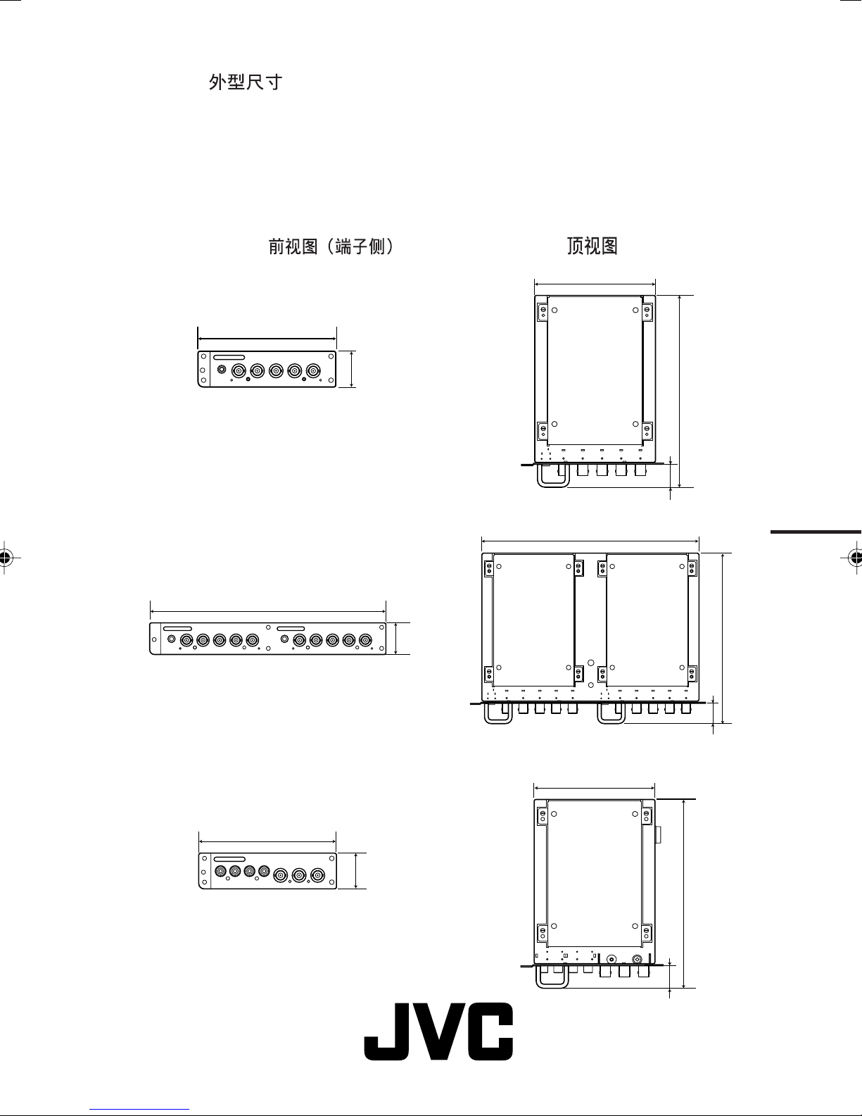
7 Dimensions/Abmessungen/Dimensions/Dimensioni/Dimensions/
Размеры/
Front View (Terminal Side)
Vorderansicht (Anschlussleiste)
Vue de face (Côté prises)
Vista frontale (Lato terminali)
Vista frontal (Lado del terminal)
Вид спереди (сторона с разъемами)
Top View
Draufsicht
Vue latérale
Vista dall’alto
Vista superior
Вид сверху
INPUT CARD FOR A JVC MONITOR
IF-CF01CMG
IF-CF01RBG
133 mm (5 1/4")
256 mm (10 1/8")
34.5 mm
(1 3/8")
34.5 mm
(1 3/8")
113 mm (4 1/2")
185 mm
(7 3/8")
22 mm (7/8")
235 mm (9 3/8")
185 mm
(7 3/8")
IF-CF21HDG
133 mm (5 1/4")
© 2005 Victor Company of Japan, Limited 1105MKH-MW-VP
34.5 mm
(1 3/8")
22 mm
(7/8")
113 mm (4 1/2")
185 mm
(7 3/8")
22 mm (7/8")
 Loading...