

Page 1

3D IMAGE PROCESSOR
IF-2D3D1
3D
イメージプロセッサ
◆
取扱説明書
3D IMAGE PROCESSOR
◆
INSTRUCTIONS
3D-BILDPROZESSOR ◆BEDIENUNGSANLEITUNG
PROCESSEUR D'IMAGE 3D
◆
MANUEL D’INSTRUCTIONS
ELABORATORE D’IMMAGINI 3D
◆
ISTRUZIONI
PROCESADOR DE IMÁGENES 3D
◆
MANUAL DE INSTRUCCIONES
◆
3D
Page 2

Major features
◆
Real-time 2D/3D conversion using unique JVC algorithms
2D/3D real-time conversion with four different 3D mixed formats for stereo video output: Can be hooked up with
most stereoscopic 3D displays
Separate L/R HD-SDI outputs: Convenient for rough editing. Compatible with 3D projection systems
Parallax adjustment and 3D intensity adjustment: Enables optimization of the 3D effect according to the scene
◆
3D L/R dual signal mixing with L/R image adjustment functions
Scope feature: Waveform monitoring and vectorscope for L/R video stream comparison
Split feature: Combines the two video streams on one screen with a movable boundary
Image Rotation function: Convenient for restricted rig setups
HD-SDI frame synchronizer: Synchronizing L/R cameras
Anaglyph and sequential viewing mode: Provides multiple ways of checking the 3D effect
◆
Compatible with a wide range of Input/Output signal formats
FUNCTION button
ADJUST MODE button
SCOPE button
OUTPUT PRESET button
INPUT SELECT button
2D-3D button
EN
Page 3

Installation and connection ...................................i
Parts identification .................................................. ii
Troubleshooting ..................................................... iii
Specifications .......................................................... iv
Index ............................................................................ v
Main features
2D-3D converter ......................................................................... 02
Converting a 2D image into a 3D image .......................03
Selecting a 3D mixing format ...........................................04
Adjusting the stereoscopic effect ...................................05
Storing the stereoscopic effect settings ........................07
LR mixer .........................................................................................08
Mixing 2-channel 2D images into one 3D image ....... 09
Functions for camera adjustment ...................................10
Checking the stereoscopic effect ....................................12
Configuring the input settings ......................................... 13
Technical information
Compatible formats ..............................................................14
Settings information ............................................................ 15
Input/output specifications ...............................................16
Other functions ......................................................................17
External control ......................................................................18
INSTRUCTIONS
3D IMAGE PROCESSOR
IF-2D3D1
EN
Page 4

02
EN
2D-3D converter
Generating 3D images from 2D images
Many 3D movies have already been shown commercially at movie theaters. The demand for 3D image content
will soon reach the mass-market, especially the home consumer market, as 3D-compatible monitors are
released for consumers and BD players become more popular.
Much new visual content must be made to be 3D-compatible as 3D-viewing environments become popular
and content demand acutely increases. Moreover, it can be expected that the market will demand 3D versions
of current 2D content. The conversion will be hard work for content suppliers.
This unit generates 3D images by real-time conversion of 2D images shot and recorded using existing methods
and formats using a conversion technology based on an original JVC algorithm.
Below is a system structure example using the unit.
Content banking system
3D-compatible monitor
IF-2D3D1
HD player
Recorder
Recorder
Editing system
Left
Right
RightLeft
Page 5

03
EN
What is a 3D image?
A 3D image is an image which looks as if it has depth
though it is displayed on a flat surface; it gives you
stereoscopic visual impression which ordinary pictures
cannot offer. You see something really come out of the
screen or you seem to go actually into it.
On a current standard 3D imaging system, it is required
to process two video signals for the left and right eyes
and display them on a 3D-compatible special monitor to
create 3D images.
Real time 2D-3D image conversion
Video signals of existing 2D content in HD SDI, the
standard format for the video industry, or HDMI, the most
popular format for video recorder/player connections, are
taken in to the unit and converted into 3D images which
are then output to a 3D-compatible visual device in HD
SDI or HDMI format.
The 3D signals processed by the unit can be output
separately as left and right HD SDI signals. It is very
convenient for 3D image post production.
Various functions for 3D image adjustment
The stereoscopic effect is based on the differences
between images the left and right eyes see, so fine
adjustment of the left and right image is indispensable
for producing quality 3D images.
This unit is equipped with two functions for adjusting the
stereoscopic effect – parallax adjustment and intensity
adjustment – and you can adjust the two parameters
while monitoring images in any of the three display
methods: normal, anaglyph and LR sequential.
Converting a 2D image into a 3D image
●
See the following pages and page ii for details of the setting procedure.
●
See Technical information (page 14 -) for details of the setting items and setting values.
1
Connect the input and output devices to the unit.
2
Press INPUT SELECT repeatedly to select an input terminal which an input device is connected to.
3
-1 Press OUTPUT PRESET and select an output terminal which an output device is connected to
using
.
3
-2 Use to select MIX or INDIVIDUAL.
4
Select a 3D image format.
5
Press 2D-3D.
2D-3D converter
Page 6
04
EN
Selecting a 3D mixing format
A 3D image is realized by viewing a picture on a 3D-compatible monitor through special glasses with shutters
or polarized filters. The monitor displays images for the left and right eyes at the same time. Each lens produces
an image for the left or right eye only and the eyes see them as a stereoscopic image.
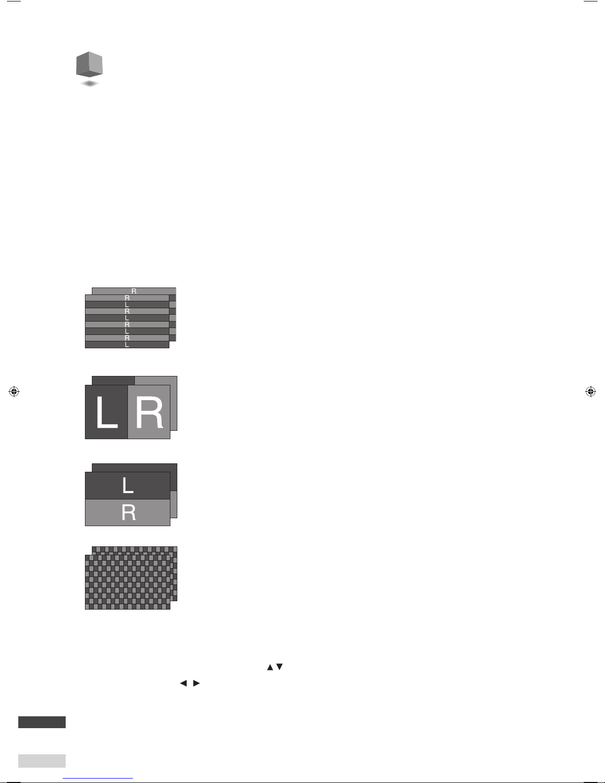
The unit is compatible with four 3D image formats, LINE BY LINE, SIDE BY SIDE H, ABOVE-BELOW and CHECKER
BOARD, that allow for various usage.
The unit executes conversion into any one of the four formats above in real-time.
●
Selectable formats vary depending on the type of input signal.
●
Selectable formats vary depending on the compatibility of the connected devices. Refer also to the instruction
manual or specifications of the connected device to check the compatibility.
Displays image stripes of the left and right images line by line one after another.
You can maintain the same horizontal resolution as the source when using a monitor with a polarized
filter system.
●
It is recommended to use another format if you use compression for recording images.
Shrinks the size of the left and right images by half and displays them side by side.
The format is compatible with most recent 3D -compatible displays. This format is very convenient
because of its high compatibility with existing recording and transmission systems though the
horizontal resolution is reduced to half.
Shrinks the left and right images by half vertically and displays them top and bottom.
The vertical resolution is reduced to half but the horizontal resolution is free from degradation if you
use a monitor with polarized filter system.
●
The format is available only when MIX is selected both in SDI OUT SELECT and HDMI OUT SELECT of
OUTPUT PRESET.
LINE BY LINE
SIDE BY SIDE H
ABOVE-BELOW
CHECKER BOARD
Displays image blocks of the left and right images one after another in a grid-like pattern.
This is an advanced format, which can reduce the feeling of image deterioration.
●
It is recommended to use another format if you use compression for recording images.
Setting
Follow the steps below to select a 3D mixing format.
1
Press OUTPUT PRESET and select 3D MIX FORMAT using .
2
Select a setting value using .
R
R
R
R
R
R
R
R
R
L
RL
L
RL
RL
RL
L
RL
L
L
L
L
L
RL
RL
R
R
L
L
R
R
L
L
RL
RL
RL
RL
R
R
L
L
R
R
L
L
RL
RL
RL
RL
RL
RL
R
R
L
L
RL
RL
RL
RL
RL
RL
RL
RL
RL
RL
RL
RL
R
R
L
L
RL
RL
L
RL
RL
RL
RL
R
R
R
R
R
L
L
L
L
R
R
R
R
L
L
L
L
RL
RL
RL
RL
RL
RL
RL
RL
R
R
R
R
R
L
L
L
L
R
R
R
R
L
L
L
L
RL
RL
RL
RL
RL
RL
RL
RL
RL
RL
RL
RL
RL
R
R
R
R
L
L
L
L
RL
RL
RL
RL
RL
RL
RL
RL
RL
RL
RL
RL
RL
RL
RL
RL
RL
RL
RL
RL
RL
RL
RL
RL
RL
R
R
R
R
R
L
L
L
L
RL
RL
RL
RL
L
RL
L
RL
L
RL
L
RL
RL
L
RL
L
RL
RL
RL
L
RL
R
L
L
L
RL
R
L
R
L
RL
RL
R
L
R
L
RL
RL
RL
R
L
RL
RL
RL
RL
RL
RL
R
L
RL
RL
RL
R
R
L
R
R
R
L
L
RL
RL
RL
R
R
L
R
R
L
RL
RL
RL
R
R
L
RL
RL
RL
RL
RL
RL
RL
R
L
RL
R
L
RL
RL
R
L
RL
RL
RL
RL
R
Page 7

05
EN
Adjusting the stereoscopic effect –
Intensity, Sub-intensity
You can control the engraving-like effect and the feeling of depth of an image by adjusting two types of
intensity: the curvature using scene detection, and the concavity and convexity using color detection. You can
adjust the image in total using the intensity adjustment, then you can adjust it partially using the sub-intensity
adjustment.
●
See page 06 for the detail of the adjustment.
Adjusting the stereoscopic effect –
Parallax
The stereoscopic effect is based on the differences between the view of the left and right eyes (parallax). This
unit can adjust degree of parallax to control stereoscopic effect.
●
See page 06 for the detail of the adjustment.
2D-3D converter
Parallax of the left and right
image is larger.
Parallax adjustment (Stronger)
Parallax of the left and right
image is smaller.
Parallax adjustment (Weaker)
[Feeling of depth]
The degree of curvature of
the whole ima ge is relatively
high and the feeling of
depth is emphasized.
[Feeling of depth]
The degree of curvature
of a whole image is small
and the feeling of depth is
moderate.
Intensity adjustment (Weaker) Intensity adjustment (Stronger)
[Engraving effect]
Less emphasis of concavity
and convexity
[Engraving effect]
Mo re em pha sis o f con cav ity
and convexity
[Engraving effect]
Partially stronger emphasis
of concavit y and convexity
[Engraving effect]
Partially weaker emphasis
of concavit y and convexity
Sub-intensity adjustment (Stronger) Sub-intensity adjustment (Weaker)
Page 8
06
EN
Adjusting the stereoscopic effect –
monitoring method
You can select a monitoring method when adjusting the stereoscopic effect of a 3D image. In addition to
ordinary 3D representation, anaglyph (the left and right images are colored differently) and LR sequential (the
left and right images are displayed alternately) are available for monitoring and adjusting parallax and intensity.
Setting
Follow the steps below to select a monitoring method.
1
Press ADJUST MODE and select a setting value using .
Monitoring method Setting value Content
Normal
PARALLAX
Parallax and intensity are adjusted using an image displayed in the format selected
in 3D MIX FORMAT.
INTENSITY
SUB INT.
Anaglyph
(ANAGLYPH MODE)
PARALLAX ANA
Parallax and intensity are adjusted using an image displayed in anaglyph.INTENSITY ANA
SUB INT. ANA
LR sequential
(LR-SEQ. MODE)
PARALLAX LRS
Parallax and intensity are adjusted using an image displayed in LR sequential.INTENSITY LRS
SUB INT. LRS
2
Adjust a setting value using . (0 - +60)
Anaglyph
Images for the left and right eyes are colored in red and blue respectively
and displayed on one screen in layers. You can check parallax adjustment by
viewing the gap between the lef t and right images even on a 2D (conventional)
monitor or without 3D glasses.
●
Be aware that it is difficult to see the colors and stereoscopic effect
correctly in anaglyphic representation.
Images for the left and right eyes are displayed alternately at 0.5-second
interval. You can view images in this method on a conventional 2D monitor
but it requires training to see them as 3D images.
LR sequential
L
R
L
R
Normal 3D images are output as they are. You can adjust images while
viewing them as natural 3D ones by using a 3D-compatible monitor.
Normal
0.5 sec.
0.5 sec.
0.5 sec.
0.5 sec.
Page 9

07
EN
Storing the stereoscopic effect settings
Configuration memory
You can save the setting values of parallax, intensity and sub-intensity.
The stored setting values can be loaded for adjustment of other images. The values can be stored in
MEMORY-1 or MEMORY-2.
Saving
1
Press FUNCTION and select MEMORY-1 or MEMORY-2 using .
2
Select SAVE using .
3
Select OK using .
The setting values are saved.
Loading
1
Press FUNCTION and select MEMORY-1 or MEMORY-2 using .
2
Select LOAD using .
3
Select OK using .
The stored setting values are loaded.
2D-3D converter
Page 10

08
EN
LR mixer
Mixing 2-channel 2D images into one 3D image
Recently 3D-compatible monitors have been released, and in consequence the demand for 3D compatibility of
video content is increasing.
This unit is equipped with a 3D image mixing function, which is indispensable for checking 3D images. The
unit's real time 3D image composition from 2-channel 2D images makes checking images easier and its flexible
monitoring methods and scopes greatly assist you with the adjustment of cameras and other devices.
Below is a system structure example using the unit.
Stereo camera rig
3D-compatible monitor
Left Right
IF-2D3D1
Page 11

What is LR mixing?
Real time 3D image mixing
3D mixing is generating 3D video signals for a
3D-compatible monitor by combining two 2D video
signals from two cameras, which are prepared for
shooting images for the left and right eyes.
2-channel 2D video signals in HD SDI, the standard format
for the video industry, are mixed to produce a 3D image
which is output to a 3D-compatible monitor in HD SDI or
HDMI format.
Rich functions for 3D image adjustment
Fine adjustment of cameras and other shooting devices is
indispensable for composing quality 3D video signals.
This unit is equipped with rich functions for monitoring
3D images and adjusting cameras and other devices,
such as waveform monitors, vectorscopes for comparing
and checking characteristics of input signals, and various
monitoring methods: Split for comparing the left and
right images, Anaglyph and LR sequential for checking the
stereoscopic effect.
LR mixer
Mixing 2-channel 2D images into one 3D image
● See the following pages and page ii for details of the setting procedure.
● See Technical information (page 14 -) for details of the setting items and setting values.
Connect the input and output devices to the unit.
1
Press INPUT SELECT repeatedly to select input terminals which input devices are connected to.
2
-1 Press OUTPUT PRESET and select an output terminal which an output device is connected to
3
using
-2 Use to select MIX or INDIVIDUAL.
3
Select a 3D image format.
4
.
09
EN
Page 12

10
EN
Functions for camera adjustment –
Waveform monitor and vectorscope
This unit is equipped with a waveform monitor and vectorscope to check input signals from the 2 channels for
assisting with the adjustment of cameras and other devices. You can select one of three indication types and
four display positions for each scope.
Select the scope and indication type you want.
Setting
Follow the steps below to select a monitoring method and its indication type.
1
Press SCOPE and select a scope using .
Setting value Indication type
Content
PARA._W.F.M.
Y Y
Select this to display the waveform monitors/vectorscopes of
the images from the HD/SDI IN 1(L) and HD/SDI IN 2(R) terminals
side by side.
Adjust the settings of the cameras so as to make the forms of the
signals as similar as possible.
PARA._V.S.
IN1_W.F.M.
Y
Select this to display the waveform monitor/vectorscope of the
image from the HD/SDI IN 1(L) terminal.
IN1_V.S.
IN2_W.F.M.
Select this to display the waveform monitor/vectorscope of the
image from the HD/SDI IN 2(R) terminal.
IN2_V.S.
BAL._W.F.M.
Y
Select this to display the differential of the signals from the HD/
SDI IN 1(L) and HD/SDI IN 2(R) terminals in waveform monitor/
vectorscope.
No signal differential (flat line on the waveform monitor and
center dot on the vectorscope) is ideal. Adjust the settings of the
cameras so as to make the differential as small as possible.
BAL._V.S.
Waveform monitor
(W.F.M.)
Y
It displays the characteristics of input signals
on a waveform chart.
It displays the characteristics of input signals on a
vectorscope.
Vectorscope
(V.S.)
Page 13

11
EN
Functions for camera adjustment –
Rotation
You can turn an input image upside-down. This is useful when you must
set a camera upside-down. The frames of the left and right images are
automatically synchronized when using this function.
Setting
1
Press FUNCTION and select ROTATE using .
2
Select a setting value using .
The three functions below are available as options of the scope function while it is activated.
Gain adjustment
You can adjust the gain of the waveform monitor/vectorscope.
1
Adjust the setting value using while displaying the waveform monitor or vectorscope. (-30 - 0 - +30)
Scope filter
Use it to activate a lowpass filter to limit the frequency band of the scope.
1
Press FUNCTION while using the scope function and select SCOPE FILTER using .
2
Select LOWPASS using .
Scope position
You can change the display position of waveform monitor/vectorscope.
1
Press FUNCTION while using the scope function and select SCOPE POSITION using .
2
Select a position using .
RIGHT LOWER
RIGHT UPPERLEFT UPPER
LEFT LOWER
LR mixer
SDI 1(L) ROTATE (inversion of the left image)
SDI 2(R) ROTATE (inversion of the right image)
The image from HD/SD SDI IN 1(L) or HD/SD SDI IN
2(R) is inverted.
● One-frame delay is required for image rotation.
The unit also delays the non-rotated image by
one frame in order to synchronize them.
One camera is set upsidedown.
OFF
Example camera setting
Page 14

12
EN
Checking the stereoscopic effect –
monitoring method
You can select a monitoring method other than normal 3D display when checking the stereoscopic effect of a 3D
image. Anaglyph (the left and right images are colored differently) and LR sequential (the left and right images are
displayed alternately) are available for checking.
Setting
1
Press ADJUST MODE and select a setting value using .
Functions for camera adjustment –
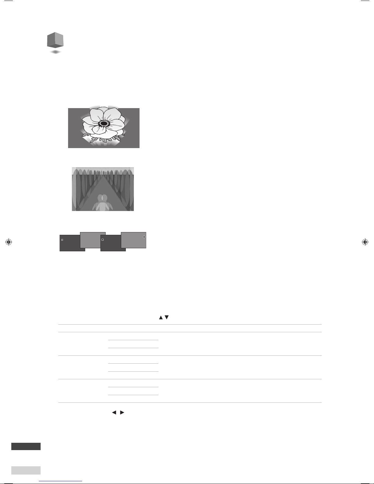
Split
The unit can divide the screen and display the left side of the left image and the right side of the right. This is
useful for checking the left and right images.
Setting
1
Press ADJUST MODE and select SPLIT MODE using .
2
Adjust the position of the dividing line using . (–60 - 0 - +60)
Example of vertical shift of
shooting position
Image from HD/SD SDI IN 1(L) Image from HD/SD SDI IN 2(R)
Example of mismatch of iris
adjustment
Example of mismatch of white
balance adjustment
Anaglyph
Images for the left and right eyes are colored in red and blue respectively
and displayed on one screen in layers. You can check parallax adjustment by
viewing the gap between the lef t and right images even on a 2D (conventional)
monitor or without 3D glasses.
●
Be aware that it is difficult to see the colors and stereoscopic effect
correctly in anaglyphic representation.
Images for the left and right eyes are displayed alternately at 0.5-second
intervals. You can view images in this method on a conventional 2D monitor
but it requires training to see them as 3D images.
LR sequential
0.5 sec.
0.5 sec.
0.5 sec.
0.5 sec.
R
L
L
R
Page 15

13
EN
Configuring the input settings
Frame synchronizer
You can synchronize the left and right input signals by locking the right input signal based on the
synchronizing signal of the left input.
1
Press FUNCTION and select FRAME SYNCHRO. using .
2
Select a setting value using .
●
The signals cannot be synchronized if the formats of the signals input to HD/SD SDI 1(L) and HD/SD SDI 2 (R) are different.
●
You cannot adjust frame synchronization on a timeline basis. If high-precision 3D images are required, turn off the function and
use generator lock on the cameras for frame synchronization.
LR inversion
You can switch the left and right of the input signals and output to the opposite channels.
1
Press INPUT SELECT repeatedly to select SDI-LR.
2
Select INVERT using .
Setting value Content
SDI-LR: NORMAL Normal output (no inversion of the left and right channel)
SDI-LR: INVERT
Outputting the signals from HD/SD SDI IN 1(L) through HD/SD SDI OUT 2(R), and those from HD/SD SDI IN 2(R)
through HD/SD SDI OUT 1(L).
LR mixer
Page 16

14
EN
2D-3D converter
LR mixer
OUTPUT
2D-3D converter
ADJUST
LR mixer
ADJUST
SCOPE**
LR INVERT
ROTATE
FRAME SYNCHRO.***
INPUT
3D MIX
FORMAT
HD/SD
SDI
HDMI
PARALLAX
INTENSITY
SUB INT.
PARALLAX ANA
INTENSITY ANA
SUB INT. ANA
PARALLAX LRS
INTENSITY LRS
SUB INT. LRS
MEMORY-1
MEMORY-2
SPLIT MODE
ANAGRYPH MODE
LR-SEQ.MODE
PARA._W.F.M.
PARA._V.S.
IN1_W.F.M./IN2_W.F.M.
IN1_V.S./IN2_V.S.
BAL._W.F.M.
BAL._V.S.
LINE BY LINE
SIDE BY SIDE H
AVOBE-BELOW
CHECKER BOARD
MIX
INDIVIDUAL
MIX
INDIVIDUAL
HD/SD SDI stereo
1080 60p*
¶¶¶¶¶¶¶¶¶ ¶¶¶¶¶¶¶¶¶¶¶¶
50p
¶¶¶¶¶¶¶¶¶ ¶¶¶¶¶¶¶¶¶¶¶¶
30p*
¶¶¶¶¶¶¶¶¶ ¶¶¶¶¶¶¶¶¶¶¶¶
25p
¶¶¶¶¶¶¶¶¶ ¶¶¶¶¶¶¶¶¶¶¶¶
24p*
¶¶¶¶¶¶¶¶¶ ¶¶¶¶¶¶¶¶¶¶¶¶
60i*
¶ ¶¶ ¶¶¶¶ ¶¶¶¶¶¶¶¶¶¶††¶
50i
¶ ¶¶ ¶¶¶¶ ¶¶¶¶¶¶¶¶¶¶††¶
720 60p*
¶¶¶¶¶¶¶¶¶ ¶¶¶¶¶¶¶¶¶¶¶¶
50p
¶¶¶¶¶¶¶¶¶ ¶¶¶¶¶¶¶¶¶¶¶¶
HD/SD SDI single
1080 60p*
¶ ¶¶¶¶¶¶¶¶¶¶¶¶¶¶¶¶¶¶¶
50p
¶ ¶¶¶¶¶¶¶¶¶¶¶¶¶¶¶¶¶¶¶
30p*
¶ ¶¶¶¶¶¶¶¶¶¶¶¶¶¶¶¶¶¶¶
25p
¶ ¶¶¶¶¶¶¶¶¶¶¶¶¶¶¶¶¶¶¶
24p*
¶ ¶¶¶¶¶¶¶¶¶¶¶¶¶¶¶¶¶¶¶
60i*
¶ ¶¶ ¶¶¶¶¶¶¶¶¶¶¶¶¶¶¶
50i
¶ ¶¶ ¶¶¶¶¶¶¶¶¶¶¶¶¶¶¶
720 60p*
¶ ¶¶¶¶¶¶¶¶¶¶¶¶¶¶¶¶¶¶¶
50p
¶ ¶¶¶¶¶¶¶¶¶¶¶¶¶¶¶¶¶¶¶
HDMI
VIDEO
1080 60p*
¶¶¶¶¶
††
¶¶¶¶¶¶¶¶¶¶¶¶¶
50p
¶¶¶¶¶
††
¶¶¶¶¶¶¶¶¶¶¶¶¶
30p*
¶¶¶¶¶
††
¶¶¶¶¶¶¶¶¶¶¶¶¶
25p
¶¶¶¶¶
††
¶¶¶¶¶¶¶¶¶¶¶¶¶
24p*
¶¶¶¶¶
††
¶¶¶¶¶¶¶¶¶¶¶¶¶
60i*
¶¶¶
††
¶¶¶¶¶¶¶¶¶¶¶¶¶
50i
¶¶¶
††
¶¶¶¶¶¶¶¶¶¶¶¶¶
720 60p*
¶¶¶¶¶
††
¶¶¶¶¶¶¶¶¶¶¶¶¶
50p
¶¶¶¶¶
††
¶¶¶¶¶¶¶¶¶¶¶¶¶
PC (DVI)
WUXGA@60****
¶ ¶¶ ¶¶¶¶¶¶¶¶¶¶¶¶¶
UXGA@60
¶ ¶¶ ¶¶¶¶¶¶¶¶¶¶¶¶¶
WSXGA+@60
¶ ¶¶¶ ¶¶¶¶¶¶¶¶¶¶¶¶¶
SXGA@60
¶ ¶¶¶ ¶¶¶¶¶¶¶¶¶¶¶¶¶
WXGA@60
¶ ¶¶¶ ¶¶¶¶¶¶¶¶¶¶¶¶¶
XGA@60
¶ ¶¶¶ ¶¶¶¶¶¶¶¶¶¶¶¶¶
SVGA@60
¶ ¶¶¶ ¶¶¶¶¶¶¶¶¶¶¶¶¶
WVGA@60
¶ ¶¶¶ ¶¶¶¶¶¶¶¶¶¶¶¶¶
VGA@60
¶ ¶¶¶ ¶¶¶¶¶¶¶¶¶¶¶¶¶
† No output when HDCP is used.
†† The bottom scanning line of the rotated image is processed into black when using the rotation function.
* The unit is compatible with frame rates of 1.00 and 1/1.001 both when the input signal is 60 Hz, 30 Hz, or 24 Hz.
(60 Hz: compatible with 59.94 Hz and 60.00 Hz, 30 Hz: compatible with 29.97 Hz and 30.00 Hz, 24 Hz: compatible with 23.97 Hz and 24.00 Hz)
** The scope function does not work when input signals are incompatible with the selected 3D mix format though the SCOPE button lights up.
*** The frame synchronizer cannot synchronize frames if the 1.00-frame-rate signal and 1/1.001-frame-rate signal are input. Unify the frame rate of input signals to 1.00
or 1/1.001.
**** WUXGA: VESA CVT-RB
●
The unit is not compatible with the signal formats which
are not listed here.
● SDI input Y/Cb/Cr = 4:2:2
Compatible formats
Page 17

15
EN
Compatible formats/Settings information
●
2D-3D converter
Button Item Setting value Initial value
2D-3D — ON/OFF OFF
SCOPE × × ×
ADJUST MODE PARALLAX 0 - +60 +13
INTENSITY 0 - +60 +23
SUB INT. 0 - +60 +40
PARALLAX ANA 0 - +60 +13
INTENSITY ANA 0 - +60 +23
SUB INT. ANA 0 - +60 +40
PARALLAX LRS 0 - +60 +13
INTENSITY LRS 0 - +60 +23
SUB INT. LRS 0 - +60 +40
FUNCTION — ON/OFF OFF
1 ROTATE OFF/SDI-1(L) ROTATE/SDI-2(R) ROTATE OFF
2 FRAME SYNCHRO. ON/OFF OFF
3 SCOPE POSITION RIGHT LOWER RIGHT LOWER
LEFT LOWER
LEFT UPPER
RIGHT UPPER
4 SCOPE FILTER FLAT/LOWPASS FLAT
5 BEEP ON/OFF ON
6 BACK LIGHT –30 - 0 - +30 0
7 MEMORY-1 SAVE/LOAD
8 MEMORY-2 SAVE/LOAD
INPUT SELECT — SDI-1(L)/SDI-2(R)/HDMI/SDI-LR:NORMAL SDI-LR:NORMAL
OUTPUT PRESET SDI OUT SELEC T MIX/INDIVIDUAL MIX
HDMI OUT SELECT MIX/INDIVIDUAL MIX
3D MIX FORMAT LINE BY LINE LINE BY LINE
SIDE BY SIDE H
ABOVE-BELOW
CHECKER BOARD
●
LR mixer
Button Item Setting value Initial value
2D-3D — ON/OFF OFF
SCOPE — ON/OFF OFF
PARA._W.F.M. –30 - 0 - +30 0
PARA._V.S. –30 - 0 - +30 0
IN1_W.F.M. –30 - 0 - +30 0
IN1_V.S. –30 - 0 - +30 0
IN2_W.F.M. –30 - 0 - +30 0
IN2_V.S. –30 - 0 - +30 0
BAL._W.F.M. –30 - 0 - +30 0
BAL._V.S. –30 - 0 - +30 0
ADJUST MODE SPLIT MODE –60 - 0 - +60 0
ANAGRYPH MODE — —
LR-SEQ. MODE — —
FUNCTION — ON/OFF OFF
1 ROTATE OFF/SDI-1(L) ROTATE/SDI-2(R) ROTATE OFF
2 FRAME SYNCHRO. ON/OFF OFF
3 SCOPE POSITION RIGHT LOWER RIGHT LOWER
LEFT LOWER
LEFT UPPER
RIGHT UPPER
4 SCOPE FILTER FLAT/LOWPASS FLAT
5 BEEP ON/OFF ON
6 BACK LIGHT –30 - 0 - +30 0
7 MEMORY-1 SAVE/LOAD
8 MEMORY-2 SAVE/LOAD
INPUT SELECT — SDI-1(L)/SDI-2(R)/HDMI/ SDI-LR:NORMAL SDI-LR:NORMAL
SDI-LR:INVERT
OUTPUT PRESET SDI OUT SELEC T MIX/INDIVIDUAL MIX
HDMI OUT SELECT MIX/INDIVIDUAL MIX
3D MIX FORMAT LINE BY LINE LINE BY LINE
SIDE BY SIDE H
ABOVE-BELOW
CHECKER BOARD
Settings information
Page 18

16
EN
Input/output specifications
Video input/output
* Throughout output
INPUT SELECT OUTPUT PRESET Output terminal (video)
LR
INVERT
2D-3D SDI OUT SELECT
HDMI OUT
SELECT
HD/SD SDI 1(L) HD/SD SDI 2(R) HDMI
When using
2D-3D
converter
HD/SD SDI IN
1(L)
—
OFF — — HD/SD SDI IN 1(L) throughout
ON
INDIVIDUAL INDIVIDUAL
HD/SD SDI IN 1(L)
3D-converted left-
channel signal
HD/SD SDI IN 1(L)
3D-converted right-
channel signal
*HD/SD SDI IN 1(L)
3D-converted left-
channel signal
MIX MIX
HD/SD SDI IN 1(L)
3D-converted mixed
signal
HD/SD SDI IN 1(L)
3D-converted mixed
signal
HD/SD SDI IN 1(L)
3D-converted mixed
signal
HD/SD SDI IN
2(R)
—
OFF — — HD/SD SDI IN 2(R) throughout
ON
INDIVIDUAL INDIVIDUAL
HD/SD SDI IN 2(R)
3D-converted left-
channel signal
HD/SD SDI IN 2(R)
3D-converted right-
channel signal
*HD/SD SDI IN 2(R)
3D-converted left-
channel signal
MIX MIX
HD/SD SDI IN 2(R)
3D-converted mixed
signal
HD/SD SDI IN 2(R)
3D-converted mixed
signal
HD/SD SDI IN 2(R)
3D-converted mixed
signal
HDMI IN —
OFF — — HDMI IN throughout
ON
INDIVIDUAL INDIVIDUAL
HDMI IN
3D-converted left-
channel signal
HDMI IN
3D-converted right-
channel signal
*HDMI IN
3D-converted left-
channel signal
MIX MIX
HDMI IN
3D-converted mixed
signal
HDMI IN
3D-converted mixed
signal
HDMI IN
3D-converted mixed
signal
When using
LR mixer
HD/SD SDI IN
1(L)
HD/SD SDI IN
2(R)
NORMAL
— INDIVIDUAL INDIVIDUAL
HD/SD SDI IN 1(L) HD/SD SDI IN 2(R) **HD/SD SDI IN 1(L)
INVERT HD/SD SDI IN 2(R) HD/SD SDI IN 1(L) **HD/SD SDI IN 2(R)
NORMAL
— MIX MIX
MIX MIX
INVERT MIX-INVERT MIX-INVERT
* A 3D-converted video signal from the HD/SD SDI IN L(1) terminal comes out of the HDMI OUT terminal when OUTPUT PRESET is set to INDIVIDUAL during 2D-3D
conversion.
** A video signal from the HD/SD SDI IN 1(L) or HD/SD SDI IN 2(R) terminal comes out of the HDMI OUT terminal when OUTPUT PRESE
T is set to INDIVIDUAL during
LR mixing.
Audio signals
Audio signal input/output
INPUT SELECT OUTPUT PRESET Output terminal (audio)
LR
INVERT
2D-3D SDI OUT SELECT HDMI OUT SELECT HD/SD SDI 1(L) HD/SD SDI 2(R) HDMI
When using
2D-3D
converter
HD/SD SDI 1(L)
HD/SD SDI 2(R)
HDMI
(When selected one
of the above)
—
OFF MIX/INDIVIDUAL MIX/INDIVIDUAL
Throughout
ON
INDIVIDUAL INDIVIDUAL
MIX MIX
When using LR
mixer
HD/SD SDI (L)
HD/SD SDI (R)
NORMAL
—
INDIVIDUAL INDIVIDUAL
HD/SD SDI 1(L) HD/SD SDI 2(R) HD/SD SDI 1(L)
INVERT HD/SD SDI 2(R) HD/SD SDI 1(L) HD/SD SDI 2(R)
NORMAL
MIX MIX
HD/SD SDI 1(L) HD/SD SDI 2(R) HD/SD SDI 1(L)
INVERT HD/SD SDI 2(R) HD/SD SDI 1(L) HD/SD SDI 2(R)
Input/output formats of audio signals
Input format of embedded audio signal Output format of embedded audio signal
HD/SD SDI IN IEC60958 PCM 48 kHz 8ch
HD/SD SDI OUT IEC60958 PCM 48 kHz 8ch
HDMI OUT IEC60958 PCM 48 kHz 2ch
HDMI IN
IEC60958 PCM 48 kHz 8ch
HD/SD SDI OUT IEC60958 PCM 48 kHz 2-8ch
HDMI OUT IEC60958 PCM 48 kHz 2ch
Dolby Digital (AC3) 5.1ch compatible
DTS 5.1ch
MPEG2-AAC stereo 2ch
HD/SD SDI OUT No output available
HDMI OUT
Dolby Digital (AC3) 5.1ch compatible*
DTS 5.1ch*
MPEG2-AAC stereo 2ch*
Page 19

17
EN
Input/output speci cations/Other functions
Other functions
You can configure the settings below to suit the unit to your operation environment.
Operation tone
The unit's beeps for confirming operations can be activated/deactivated.
1
Press FUNCTION and select BEEP using .
2
Select a setting value using .
Backlight
You can adjust the brightness of the information display.
1
Press FUNCTION and select BACK LIGHT using .
2
Adjust the setting value using .
Control key lock
You can deactivate the buttons on the front of the unit.
1
Press and hold and simultaneously when the information display indicates the current input (e.g.: SDI-1(L)).
KEY LOCKED! appears on the information display and the buttons on the front of the unit are deactivated.
To release the lock, press and hold
and simultaneously again.
5BEEP
ON
Setting items
Setting value
KKEED!YOLC
Page 20

18
EN
External control
You can control the unit using a PC or the special control unit connected to the RS-232C terminal on the rear of
the unit.
●
Connect the RS-232C straight-through cable (purchased separately) to the RS-232C terminal on the rear of the unit. (See page ii.)
Control specifications
●
Communication specifications
●
Terminal specifications
This is a male
terminal.
Pin number Signal
1
—
2
RXD
3
TXD
4
—
5
GND
6
—
7
—
8
—
9
—
●
Connection
1
Connect the PC to the RS-232C terminal on the rear of the unit using an RS-232C extension cable (purchased separately).
2
Send the log in command from the PC to log into the unit.
REMOTE MODE appears on the information display and the unit becomes operatable from the PC. You cannot operate the unit
using the buttons while the PC is logged into it.
When the operation has finished, send the log off command to the unit from the PC to log off.
●
If you cannot log off the unit from the PC, press and hold and . Communication is forcibly terminated. The buttons on
the unit remain locked after the forcible shutting down. Press and hold and again to release the lock. (See page 17.)
●
Communication is automatically terminated if the unit is turned off during communication. Log in from the PC again to
restart external control.
Command outline
You can control the unit by sending commands from an external device.
●
Communication example
●
Command structure
a: Header ! : Control command from an external device
? : Reference command from an external device
@ : Response command from the unit
b: Device ID 00 (Fixed)
c: Command
Command list (see page 19)
d: Data
e: Exit code Cr (0Dh)
●
Baud rate: 9600bps
●
Data bits: 8 bits
●
Parity: Odd parity
●
Stop bits: 1 bits
●
Flow control: None
●
Communication code: ASCII code
1
!00BCN1000Cr
2
@00BOK.000Cr
3
External control
device
IF-2D3D1
1
Command for starting
communication
2
Acceptance from the unit
3
The unit becomes operatable
from the external control device.
REM MOOTE ED
! 00BCN1000Cr
b c d e
a
Page 21

19
EN
External control
●
Command list
●
Assign parameters on the left column at "*".
●
Make the order of commands the same as that of the button operation on the unit. The commands sent in a wrong order will be
ignored.
Function
Command
Parameter
Logging in (starting communication)
!00BCN1000Cr
—
Logging off (quitting communication)
!00BCN0000Cr
—
Starting operation of INPUT SELECT
!00INPUT00Cr
—
Selecting an input terminal
!00INPSE0*Cr
0x00: SDI-LR/0x01: SDI-1(L)
0x02: SDI-2(R)/0x03: HDMI
Turning LR inversion on/off
!00BOTHP0*Cr
0x00: NORMAL/0x01: INVERT
Starting operation of OUTPUT PRESET
!00OUTPU00Cr
—
Selecting an SDI output type
!00SDIMX0*Cr
0x00: MIX/0x01: INDIVIDUAL
Selecting an HDMI output type
!00HDMIM0*Cr
0x00: MIX/0x01: INDIVIDUAL
Selecting a 3D mixing format
!003DFOR0*Cr
0x00: LINE BY LINE/0x01: SIDE BY SIDE H
0x02: ABOVE-BELOW/0x03: CHECKER BOARD
Starting operation of FUNCTION
!00MMENU00Cr
—
Turning the rotation function on/off
!00SDIRT0*Cr
0x00: OFF/0x01: SDI-1(L)ROTATE
0x02: SDI-2(R)ROTATE
Turning the frame synchronizer on/off
!00FRASY0*Cr
0x00: OFF/0x01: ON
Turning the operation tones on/off
!00BEEPA0*Cr
0x00: ON/0x01: OFF
Adjusting the brightness of the information display
!00BACKL+*Cr
!00BACKL−*Cr
0x00 - 0x1E: 0 - +30
0xFF - 0xE2: −1 - −30
Storing settings into memory
!00MEMSV0*Cr
0x00: MEMORY-1/0x01: MEMORY-2
Loading settings from memory
!00MEMLD0*Cr
0x00: MEMORY-1/0x01: MEMORY-2
Starting operation of the scope function
!00SCOPE00Cr
—
Displaying the waveform monitor or vectorscope
!00SCMOD0*Cr
0x00: OFF
0x01: Waveform monitor
0x02: Vectorscope
Assigning an input source for a scope
!00SCSIG0*Cr
0x00: PARA. (SDI-LR)/0x01: BAL. (SDI-LR)
0x02: SDI-IN 1(L)/0x03: SDI-IN 2(R)
Selecting a scope position
!00SCPOS0*Cr
0x00: RIGHT LOWER/0x01: LEFT LOWER
0x02: LEFT UPPER/0x03: RIGHT UPPER
Turning the lowpass filter on/off
!00SCPFI0*Cr
0x00: OFF/0x01: ON
Adjusting the gain of the waveform monitor
!00SCWFG+*Cr
!00SCWFG−*Cr
0x00 - 0x1E: 0 - +30
0xFF - 0xE2: −1 - −30
Adjusting the gain of the vectorscope
!00SCVEG+*Cr
!00SCVEG−*Cr
0x00 - 0x1E: 0 - +30
0xFF - 0xE2: −1 - −30
Starting operation of ADJUST MODE
!00ADJUS00Cr
—
Selecting the display format of ADJUST MODE
!00ADJMD0*Cr
0x00: OFF
0x01: SPLIT MODE
0x02: ANAGLYPH
0x03: LR-SEQ. MODE
0x04: PARALLAX
0x05: INTENSITY
0x06: PARALLAX ANA
0x07: INTENSITY ANA
0x08: PARALLAX LRS
0x09: INTENSITY LRS
0x0a: SUB INT.
0x0b: SUB INT. ANA
0x0c: SUB INT. LRS
Moving the dividing line of split
!00ADJOS+*Cr
!00ADJOS−*Cr
0x00 - 0x3C: 0 - +60
0xFF - 0xC4: −1 - −60
Adjusting parallax
!00ADJPX0*Cr
0x00 - 0x3C: 0 - +60
Adjusting intensity
!00ADJIY0*Cr
0x00 - 0x3C: 0 - +60
Adjusting sub-intensity
!00ADJSI0*Cr
0x00 - 0x3C: 0 - +60
Starting operation of 2D-3D
!002D/3D00Cr
—
Turning the 2D-3D converter on/off
!00CONVE0*Cr
0x00: OFF/0x01: ON
Normal status
@00BOK.000Cr
—
Abnormal status
@00BNGn***Cr
n=0: illegal command/n=1: illegal setting value
n=2: unexecutable in the current mode
Page 22

i
EN
Installation and connection
Accessories
●
Main unit
●
Power cord
●
Power cord holder/tapping screws x 2 (4 mm)
●
EIA rack mounting adapters x 2/tapping screws x 8 (3 mm)
Installation
Read the safety precautions (separate sheet) carefully and install the device properly.
Connecting the power cord and attaching the power cord holder
Attach the power cord holder to the back of the unit to prevent accidental disconnection of the cord.
●
Ground the earth plug of the power cable to the earth terminal of the AC outlet.
●
The holder consists of two parts: the cord case and the case cover.
Cautions
●
Do not use any screws other than those supplied.
●
Push the cover into the case and check that the power plug is connected rmly.
Mounting the unit in to an EIA rack
Read the safety precautions (separate sheet) carefully before installing this unit in an EIA rack.
Case
To take off the cover
31
AC IN terminal
2
Cover
Take off the feet on the bottom of
the unit.
Attach the EIA rack mounting adapters
with the supplied screws.
●
Fit the screws in order shown.
Install the unit to an EIA rack.
●
Screws for mounting are not
supplied. Use the special
screws for EIA racks (purchased
separately).
12 3
Page 23

ii
Installation and connection/Parts identification
OUTPUT PRESET
button
ADJUST MODE buttonArrow buttons
(
)
Information display
FUNCTION button
SCOPE button
INPUT SELECT button
2D-3D button
POWER switch
EN
Parts identification
Front
POWER* Use it to turn on/off the power.
2D-3D* Press it to turn on/off the 2D-3D converter. (page 03)
INPUT SELECT* Press it to select an input terminal. (pages 03, 09, 13)
OUTPUT PRESET* Press it to select an output terminal and output type. (pages 03, 04, 09)
SCOPE* Press it to turn on/off the scope function. Setting items of the scope function are indicated on the
information display when the function is turned on. (pages 10, 11)
ADJUST MODE* Press it to turn on/off ADJUST MODE. Setting items of the functions of ADJUST MODE are indicated on the
information display when turned on. (pages 06, 12)
FUNCTION* Press it to use functions for camera adjustment (see page 11) and other functions (see pages 07, 13, 17).
(Arrow buttons)
(Up and down buttons)
Use them to select an item.
(Left and right buttons)
Use them to adjust a value.
Information display Indicates information such as menu items and their settings.
* Lights up while activated.
Rear
HD/SD SDI IN 1(L) terminal
(Audio and visual signals)
HD/SD SDI IN 2(R) terminal
(Audio and visual signals)
HDMI IN terminal
(Audio and visual signals)
RS-232C terminal
(to PC)
HD/SD SDI OUT 1(L) terminal
(Audio and visual signals)
HD/SD SDI OUT 2(R) terminal
(Audio and visual signals)
HDMI OUT terminal
(Audio and visual signals)
Reclock out terminal
AC IN terminal
Page 24

iii
EN
Troub leshooting
After turning the unit off and on
If you turn the unit off during setting, the unit will use the
previous settings next time it is turned on.
●
The last selected item appears highlighted as the unit turns
on if you turned the unit off during setting the 2D-3D or scope
function last time.
●
The last selected item appears as ADJUST is pressed.
●
The initial value appears as FUNCTION, INPUT SELECT or
OUTPUT PRESET is pressed.
General
Cannot turn on the unit.
●
Connect the power cord properly. (See page i.)
Cannot operate the unit properly.
●
Turn off the POWER switch on the front of the unit and turn it
on again. If the problem is not solved, consult your dealer.
The buttons on the front of the unit do not work.
●
Deactivate the lock. (page 17)
No operation tone comes out when pressing a button.
●
Turn on the operation tone. (page 17)
No indication on the information display.
●
Nothing is indicated on the information display while
controlling the unit from an external device. Log off the
external device. (page 18)
The information display is too bright.
●
Adjust the brightness of the backlight. (page 17)
Input and output
No picture is displayed.
●
Select the appropriate input/output settings.
●
Connect external devices properly.
●
Turn on the external devices and start playback.
No picture from an HDMI device.
●
Use a cable marked with the HDMI logo. (Please use a High
Speed HDMI™ cable, which is tested to carry an HD signal of
1080p and higher.)
No 3D image is displayed.
●
Press 2D-3D.
●
Input the same resolution signals to both the HD/SD SDI IN 1(L)
and HD/SD SDI IN 2(R) terminals.
●
Input a signal compatible with the unit.
A signal input to the HDMI IN terminal does not come out
of the HD/SD SDI OUT terminals.
●
The HD/SD SDI OUT terminals cannot be used for output when
the input signal is formatted for PCs or is HDCP-encrypted. Use
the HDMI OUT terminal for output.
A signal input to the HD/SD SDI IN terminal does not
come out of the HDMI OUT terminal.
●
The format of the signal is incompatible with the HDMI OUT
terminal. See Compatible formats (page 14) for details.
Signal format
An SDI embedded audio signal does not come out of the
HD/SD SDI OUT terminal.
●
The format of the input audio signal is not compatible with
embedding. See Input/output specifications (page 16) for
details.
An audio signal does not come out of the HDMI OUT
terminal/The number of audio channels decreases when
using the HDMI OUT terminal.
●
The format of the input audio signal is not compatible with
HDMI output/has a limited number of channels when using
HDMI output. See Input/output specifications (page 16) for
details.
To check the format of the input signal...
●
Press INPUT SELECT. The signal format of the current input
appears on the information display.
To check the output setting...
●
Press OUTPUT PRESET. The current output setting appears on
the information display.
2D-3D conversion
Images are not converted into 3D after pressing 2D-3D.
●
Images are not converted into 3D when INPUT SELECT is set
to SDI-LR. Select another input to make 2D-3D conversion
effective.
Some functions such as 2D-3D conversion do not work.
●
Some functions do not work depending on the format of the
input signal and/or settings selected. See Compatible formats
(page 14) for available functions of each input signal format.
The 2D-3D button flashes and images are not converted
into 3D after pressing it.
●
The format of the video signal is not compatible with
conversion or the selected 3D mixing format. See Compatible
formats (page 14) for details.
The stereoscopic effect is hard to see.
●
The conversion generates virtual 3D images using an image-
recognition algorithm. The conversion may be less effective
depending on the type of the source image.
LR mixing
The LR mixing function does not work.
●
The 2D signals are not mixed when OUTPUT PRESET is set to
INDIVIDUAL. Select MIX in OUTPUT PRESET to mix the signals
and generate a 3D image.
●
The format of the video signal is not compatible with the
selected 3D mixing format. See Compatible formats (page 14)
for details.
The image blurs when mixing.
●
Turn the frame synchronizer on. (page 13)
Input images are not synchronized.
●
Turn the frame synchronizer on or off. (page 13)
●
This unit cannot correct the time base difference between two
video signals. Synchronize them using a time base corrector or
another device or use generator lock on video output devices
before using the unit.
●
Frame rates of the video signals are different (e.g.: 60 Hz and
59.94 Hz). Check the frame rate on the video output devices.
Waveform monitor/vectorscope is not displayed by
pressing SCOPE.
●
The waveform monitor/vectorscope is not displayed when
INPUT SELECT is set to SDI-1(L), SDI-2(R) or HDMI. Select SDI-LR
to use the waveform monitor or vectorscope.
Page 25

iv
Troubleshooting/Specifications
EN
Specifications
Speci cations
General Model name IF-2D3D1
Power requirements AC 120 V - 240 V, 50 Hz/60 Hz
Rated current 0.2 A
Power consumption 10 W (approx.)
Dimensions 430 mm × 48.5 mm × 248.5 mm (17” × 2” × 9 7/8”) (W×H×D)
Mass 2.5 kg (5.5 lbs) (excluding accessories)
Input/Output Input terminals HD/SD SDI BNC terminals 0.8 V (p-p) x 2
HDMI 1 (version 1.3 compliant)
Output terminals
HD/SD SDI
BNC terminals 0.8 V (p-p) x 2
BNC terminals 0.8 V (p-p) x 2 (Reclock out)
HDMI 1 (version 1.3 compliant)
Audio HD/SD SDI HD/SD embedded audio 1-2G 8 channels (48 kHz)
HDMI linear PCM 8 channels (48 kHz)
External control RS-232C terminal (D-sub 9 pin) x 1
Others Operation
environment
Temperature: 5°C - 35°C, humidity 20% - 80% (No condensation)
(Operatable environment may vary depending on the condition of the installation
place.)
Dimensions
42mm
(1 3/4”)
26±0.2mm
(1 1/8”)
75mm (3”)
40±0.2mm
(1 5/8”)
32mm
(1 3/8”)
481.7mm (19”)
465mm (13 3/8”)
430mm (17”)
31.8mm
(1 3/8”)
21.6mm
(7/8”)
392mm (15 1/2”)
248.5mm (9 7/8”)
230mm (9 1/8”)
48.5mm
(2”)
178mm (7 1/8”)
Page 26

v
EN
Numbers
2D-3D . . . . . . . . . . . . . . . . . . . . . . . . . . . . . . . . . 03, 15, ii, iii
2D-3D converter . . . . . . . . . . . . . . . . . . . . . . . . . 02, 16, 19
3D mixing format . . . . . . . . . . . . . . . . . . . . 04, 06, 09, 19
Alphabet
A
ABOVE-BELOW . . . . . . . . . . . . . . . . . . . . . . . . . . . . . 04, 14
ADJUST MODE . . . . . . . . . . . . . . . . . . . . . . . .06, 12, 15, ii
Anaglyph. . . . . . . . . . . . . . . . . . . . . . . . . 03, 06, 09, 12, 19
B
Backlight . . . . . . . . . . . . . . . . . . . . . . . . . . . . . . . . . . . . . . .17
C
CHECKER BOARD . . . . . . . . . . . . . . . . . . . . . . . . . . . 04, 14
Control key lock . . . . . . . . . . . . . . . . . . . . . . . . . . . . . . . .17
F
Frame synchronizer . . . . . . . . . . . . . . . . . . . . . . . . . . . . .13
FUNCTION . . . . . . . . . . . . . . . . . . . . . . . . 07, 11, 13, 15, ii
H
HD/SD SDI IN 1(L) . . . . . . . . . . . . . . . . . . . . . . . . 11 - 16, ii
HD/SD SDI IN 2(R) . . . . . . . . . . . . . . . . . . . . . . . . 11 - 16, ii
HD/SD SDI OUT 1(L) . . . . . . . . . . . . . . . . . . . . . 14 - 16, ii
HD/SD SDI OUT 2(R) . . . . . . . . . . . . . . . . . . . . . 14 - 16, ii
HDMI IN . . . . . . . . . . . . . . . . . . . . . . . . . . . . . . . . . 14 - 16, ii
HDMI OUT . . . . . . . . . . . . . . . . . . . . . . . . . . . . . . . 14 - 16, ii
Index
I
Information display . . . . . . . . . . . . . . . . . . . . . . . . . . . . . . ii
INPUT SELECT . . . . . . . . . . . . . . . . . . . . . . . . . . .13, 15, 16
INTENSITY . . . . . . . . . . . . . . . . . . . . . . . 05 - 07, 14, 15, 19
L
LINE BY LINE . . . . . . . . . . . . . . . . . . . . . . . . . . . . . 04, 14, 15
LR inversion . . . . . . . . . . . . . . . . . . . . . . . . . . . . . . . . . . . .13
LR sequential . . . . . . . . . . . . . . . . . . . . . 03, 06, 09, 12, 19
LR mixer . . . . . . . . . . . . . . . . . . . . . . . . . . . . . . . . . . . . 08, 16
O
Operation tone . . . . . . . . . . . . . . . . . . . . . . . . . . . . . . . . .17
OUTPUT PRESET . . . . . . . . . . . . . . . . . . . . . . . . .04, 15, 16
P
PARALLAX . . . . . . . . . . . . . . . . . . . . . . . 05 - 07, 14, 15, 19
POWER . . . . . . . . . . . . . . . . . . . . . . . . . . . . . . . . . . . . . . . . . . ii
R
Rotation . . . . . . . . . . . . . . . . . . . . . . . . . . . . . . . . . . . . . . . .11
RS-232C . . . . . . . . . . . . . . . . . . . . . . . . . . . . . . . . . . . . . .18, ii
S
Scope . . . . . . . . . . . . . . . . . . . . . . . . . . . . . . . . . . . . . . . . . .10
Scope filter . . . . . . . . . . . . . . . . . . . . . . . . . . . . . . . . . . . . .11
Scope position . . . . . . . . . . . . . . . . . . . . . . . . . . . . . . . . .11
SIDE BY SIDE H . . . . . . . . . . . . . . . . . . . . . . . . . .04, 14, 15
Split . . . . . . . . . . . . . . . . . . . . . . . . . . . . . . . . . . . . . 09, 12, 19
Page 27

vi
Index
EN
V
Vectorscope . . . . . . . . . . . . . . . . . . . . . . . . . . . . . . . . . . . .10
W
Waveform monitor . . . . . . . . . . . . . . . . . . . . . . . . . . . . .10
Page 28

 Loading...