

Page 1
SERVICE MANUAL
LCD PANEL TELEVISION
YA45720068
LT-37X987/KA
BASIC CHASSIS
FL4
1 PRECAUTION. . . . . . . . . . . . . . . . . . . . . . . . . . . . . . . . . . . . . . . . . . . . . . . . . . . . . . . . . . . . . . . . . . . . . . . . . 1-3
2 SPECIFIC SERVICE INSTRUCTIONS . . . . . . . . . . . . . . . . . . . . . . . . . . . . . . . . . . . . . . . . . . . . . . . . . . . . . . 1-6
3 DISASSEMBLY . . . . . . . . . . . . . . . . . . . . . . . . . . . . . . . . . . . . . . . . . . . . . . . . . . . . . . . . . . . . . . . . . . . . . . . 1-9
4 ADJUSTMENT . . . . . . . . . . . . . . . . . . . . . . . . . . . . . . . . . . . . . . . . . . . . . . . . . . . . . . . . . . . . . . . . . . . . . . . 1-15
5 TROUBLESHOOTING . . . . . . . . . . . . . . . . . . . . . . . . . . . . . . . . . . . . . . . . . . . . . . . . . . . . . . . . . . . . . . . . . 1-21
COPYRIGHT © 2006 Victor Company of Japan, Limited
TABLE OF CONTENTS
No.YA457
2006/8
Page 2
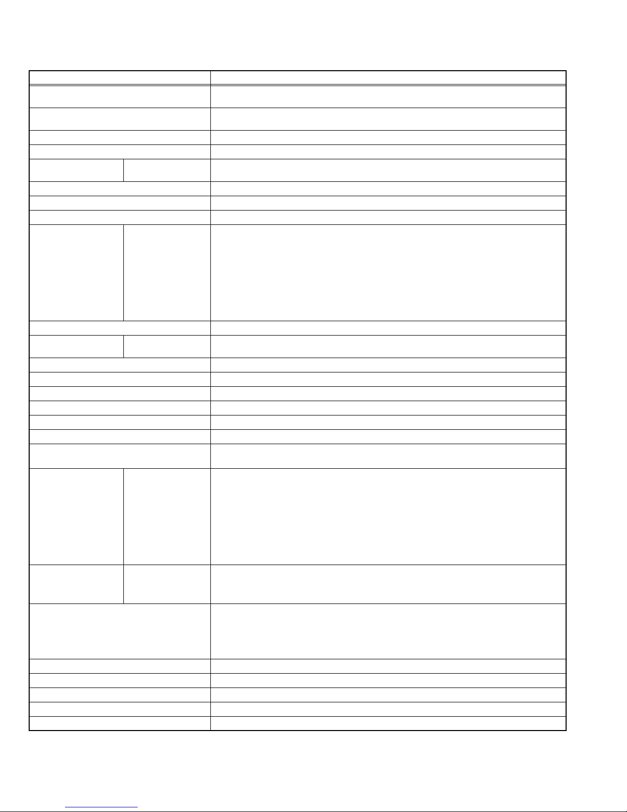
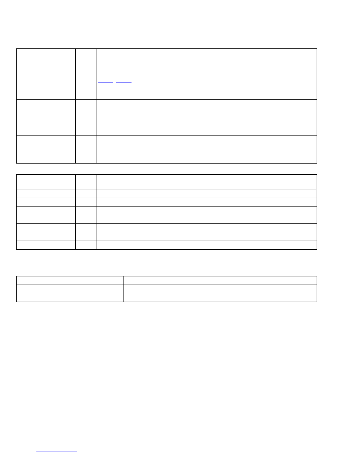
SPECIFICATION
Items Contents
Dimensions ( W × H × D ) 91.9 cm × 65.2 cm × 31.2 cm (36-1/4" × 25-5/8" × 12-1/4") [Included stand]
Mass 21.6 kg (47.5 lbs) [Included stand]
Power Input AC120 V , 60 Hz
Power Consumption 185 W (Max)
TV RF System
(Analog / Digital)
Color System (Analog) NTSC
Stereo System (Analog) BTSC (Multi Channel Sound)
Teletext System (Analog) Closed caption (T1-T4 / CC1-CC4)
TV Receiving Channels
and Frequency (Analog)
TV / CATV Total Channel 191 Channels
Intermediate Frequency
(Analog)
Color Sub Carrier Frequency (Analog) 3.58 MHz
LCD panel 37V-inch wide aspect (16:9)
Screen Size Diagonal : 94.0 cm (H:82.0 cm × V :46.1 cm)
Display Pixels Horizontal : 1366 dots × Vertical : 768 dots (W-XGA)
Audio Power Output 10 W + 10 W
Speaker 4.0 cm × 16.0 cm, twin oblique × 2
Antenna Terminal
(VHF/UHF, ATSC / DIGITAL CABLE IN)
Video / Audio input
[INPUT-1/2/3]
Digital input
[DIGITAL-IN 1/2]
PC (RGB) Input D-sub 3-row 15pin × 1
Audio output (Fix) 250 mV (rms), Low impedance, RCA pin jack × 2
iLink Input/Output TS In/Out (4-pin, S400) × 2, IEEE1394 compliant DTCP digital copy protection compatible
Digital Audio Optical Output Digital SPDIF × 1
Headphone 3.5 mm stereo mini jack × 1
Remote Control Unit RM-C18G (AA/R6 / UM-3 battery × 2)
Component Video
VHF Low
VHF High
Video IF
Sound IF
[INPUT-1]
1125i / 750p
525p / 525i
S-Video
[INPUT-1/2]
Design & specifications are subject to change without notice.
91.9 cm × 60.4 cm × 12.1 cm (36-1/4" × 23-7/8" × 5-3/4") [Included stand]
18.9 kg (41.6 lbs) [TV only]
Analog
CCIR (M)
Digital
ATSC terrestrial / Digital cable
02 ch - 06 ch : 54 MHz - 88 MHz
07 ch - 13 ch : 174 MHz - 216 MHz
UHF
14 ch - 69 ch : 470 MHz - 806 MHz
CATV
54 MHz - 804 MHz
Low Band : 02 - 06
High Band : 07 - 13
Mid Band : 14 - 22
Super Band : 23 - 36
Hyper Band : 37 - 64
Ultra Band : 65 - 94, 100 - 135
Sub Mid Band : 01, 96 - 99
45.75 MHz
41.25 MHz (4.5 MHz)
F-type connector, 75Ω unbalanced, coaxial × 1
RCA pin jack × 3
Y : 1 V (p-p) (Sync signal: 0.35V(p-p), 3-value sync.), 75 Ω
Pb/Pr : ±0.35V(p-p), 75 Ω
Y : 1 V (p-p), Positive (Negative sync provided), 75 Ω
Cb/Cr : 0.7V(p-p), 75 Ω
Mini-DIN 4 pin × 2
Y: 1 V (p-p), Positive (Negative sync provided), 75 Ω
C: 0.286V (p-p) (Burst signal), 75 Ω
1 V (p-p), Positive (Negative sync provided), 75 Ω, RCA pin jack × 3
Video
500 mV (rms), High impedance, RCA pin jack × 6
Audio
Video
HDMI 2-row 19pin connector × 2
(Digital-input terminal is not compatible with picture signals of personal computer)
Audio
Digital: HDMI 2-row 19pin connector × 2
Anarog: 500mV(rms) (-4dBs), high impedance, RCA pin jack × 2
R/G/B : 0.7V (p-p), 75Ω
HD / VD : 1V (p-p) to 5V (p-p), high impedance
< Available signal >
VGA : 640 pixels × 480 pixels (Horizontal : 31.5kHz / Vertical : 60Hz)
XGA : 1024 pixels × 768 pixels (Horizontal : 48.4kHz / Vertical : 60Hz)
1-2 (No.YA457)
Page 3

SECTION 1
PRECAUTION
1.1 SAFETY PRECAUTIONS
(1) The design of this product contains special hardware,
many circuits and components specially for safety
purposes. For continued protection, no changes should be
made to the original design unless authorized in writing by
the manufacturer. Replacement parts must be identical to
those used in the original circuits. Service should be
performed by qualified personnel only.
(2) Alterations of the design or circuitry of the products should
not be made. Any design alterations or additions will void
the manufacturer's warranty and will further relieve the
manufacturer of responsibility for personal injury or
property damage resulting therefrom.
(3) Many electrical and mechanical parts in the products have
special safety-related characteristics. These
characteristics are often not evident from visual inspection
nor can the protection afforded by them necessarily be
obtained by using replacement components rated for
higher voltage, wattage, etc. Replacement parts which
have these special safety characteristics are identified in
the parts list of Service manual. Electrical components
having such features are identified by shading on the
schematics and by ( ) on the parts list in Service
manual. The use of a substitute replacement which does
not have the same safety characteristics as the
recommended replacement part shown in the parts list of
Service manual may cause shock, fire, or other hazards.
(4) Don't short between the LIVE side ground and
ISOLATED (NEUTRAL) side ground or EARTH side
ground when repairing.
Some model's power circuit is partly different in the GND.
The difference of the GND is shown by the LIVE : ( ) side
GND, the ISOLATED (NEUTRAL) : ( ) side GND and
EARTH : ( ) side GND.
Don't short between the LIVE side GND and ISOLATED
(NEUTRAL) side GND or EARTH side GND and never
measure the LIVE side GND and ISOLATED (NEUTRAL)
side GND or EARTH side GND at the same time with a
measuring apparatus (oscilloscope etc.). If above note will
not be kept, a fuse or any parts will be broken.
(5) When service is required, observe the original lead dress.
Extra precaution should be given to assure correct lead
dress in the high voltage circuit area. Where a short circuit
has occurred, those components that indicate evidence of
overheating should be replaced. Always use the
manufacturer's replacement components.
(6) Isolation Check (Safety for Electrical Shock Hazard)
After re-assembling the product, always perform an
isolation check on the exposed metal parts of the cabinet
(antenna terminals, video/audio input and output terminals,
Control knobs, metal cabinet, screw heads, earphone jack,
control shafts, etc.) to be sure the product is safe to operate
without danger of electrical shock.
a) Dielectric Strength Test
The isolation between the AC primary circuit and all metal
parts exposed to the user, particularly any exposed metal
part having a return path to the chassis should withstand a
voltage of 3000V AC (r.m.s.) for a period of one second. (.
. . . Withstand a voltage of 1100V AC (r.m.s.) to an
appliance rated up to 120V, and 3000V AC (r.m.s.) to an
appliance rated 200V or more, for a period of one second.)
This method of test requires a test equipment not generally
found in the service trade.
b) Leakage Current Check
Plug the AC line cord directly into the AC outlet (do not use
a line isolation transformer during this check.). Using a
"Leakage Current Tester", measure the leakage current
from each exposed metal part of the cabinet, particularly
any exposed metal part having a return path to the chassis,
to a known good earth ground (water pipe, etc.). Any
leakage current must not exceed 0.5mA AC (r.m.s.).
However, in tropical area, this must not exceed 0.2mA AC
(r.m.s.).
Alternate Check Method
Plug the AC line cord directly into the AC outlet (do not
use a line isolation transformer during this check.). Use
an AC voltmeter having 1000Ω per volt or more
sensitivity in the following manner. Connect a 1500Ω
10W resistor paralleled by a 0.15µF AC-type capacitor
between an exposed metal part and a known good earth
ground (water pipe, etc.). Measure the AC voltage
across the resistor with the AC voltmeter. Move the
resistor connection to each exposed metal part,
particularly any exposed metal part having a return path
to the chassis, and measure the AC voltage across the
resistor. Now, reverse the plug in the AC outlet and
repeat each measurement. Any voltage measured must
not exceed 0.75V AC (r.m.s.). This corresponds to
0.5mA AC (r.m.s.).
However, in tropical area, this must not exceed 0.3V AC
(r.m.s.). This corresponds to 0.2mA AC (r.m.s.).
AC VOLTMETER
(HAVING 1000 /V,
OR MORE SENSITIVITY)
0.15 F AC-TYPE
GOOD EARTH GROUND
1500 10W
PLACE THIS PROBE
ON EACH EXPOSED
ME TAL PAR T
(No.YA457)1-3
Page 4
1.2 INSTALLATION
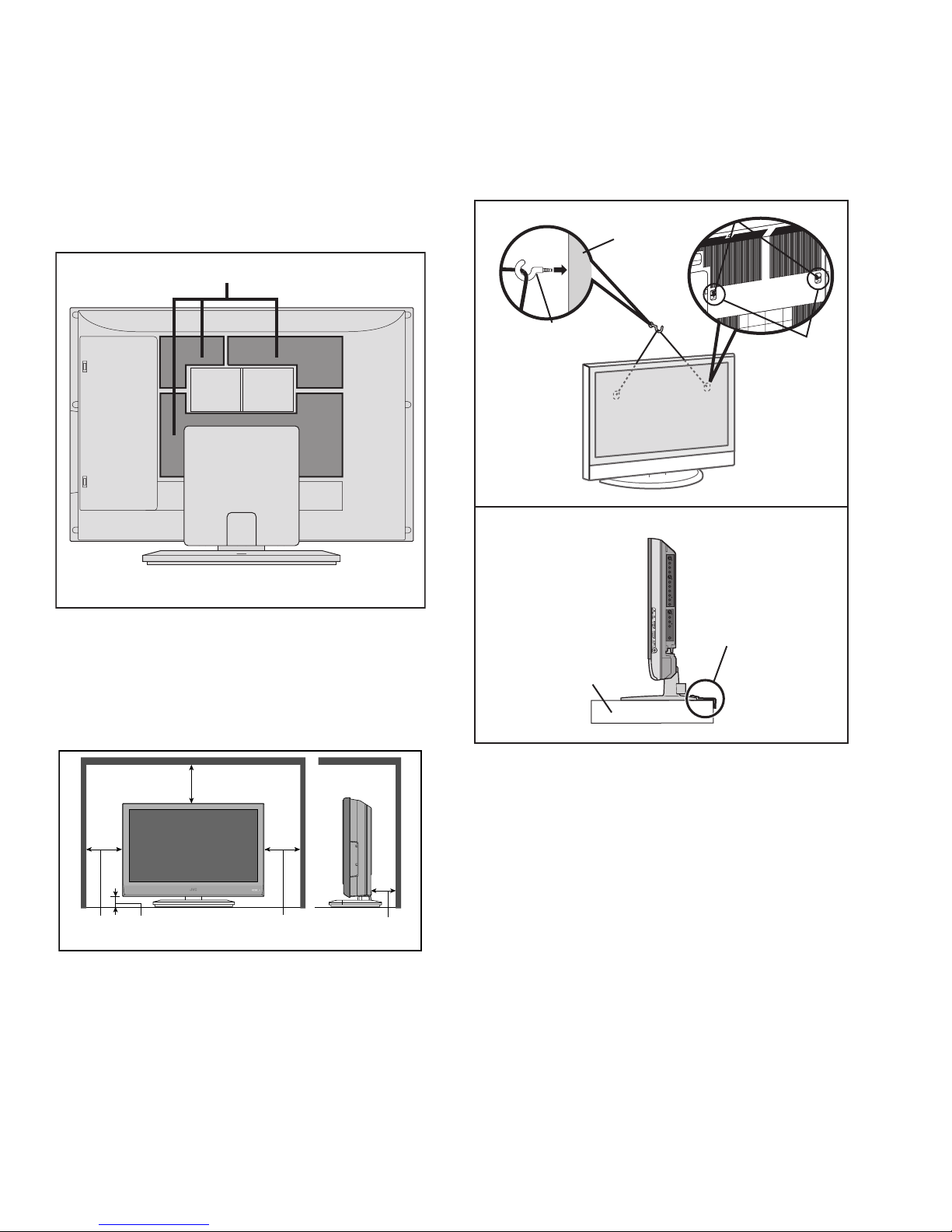
1.2.1 HEAT DISSIPATION
If the heat dissipation vent behind this unit is blocked, cooling
efficiency may deteriorate and temperature inside the unit will
rise. The temperature sensor that protects the unit will be
activated when internal temperature exceeds the pre-determined
level and power will be turned off automatically.Therefore,
please make sure pay attention not to block the heat dissipation
vent as well as the ventilation outlet behind the unit and ensure
that there is room for ventilation around it.
Ventilation hole
1.2.3 INSTALLATION REQUIREMENTS
To ensure safety in an emergency such as an earthquake, and
to prevent accidents, ensure that measures are taken to prevent
the TV dropping or falling over.
Tie commercially available tough cord(s) to the hooks in the back
of the TV, and fix the TV to solid walls or columns.
< FRONT VIEW >
WALL
*Diagram differs from actual appearance.
1.2.2 INSTALLATION REQUIREMENTS
Ensure that the minimal distance is maintained, as specified
below, between the unit with and the surrounding walls, as well
as the floor etc.Install the unit on stable flooring or stands.Take
precautionary measures to prevent the unit from tipping in order
to protect against accidents and earthquakes.
HOOK
HOOK
*Diagram differs from actual appearance.
< SIDE VIEW >
It fixes in a band.
TV STAND
*Diagram differs from actual appearance.
200mm
50mm150mm 150mm 50mm
*Diagram differs from actual appearance.
1-4 (No.YA457)
1.2.4 NOTES ON HANDLING
(1) WHEN TAKING UNIT OUT OF A PACKING CASE
When taking the unit out of a packing case, do not grasp
the upper part of the unit. If you take the unit out while
grasping the upper part, the LCD PANEL may be damaged
because of a pressure. Instead of grasping the upper part,
put your hands on the lower backside or sides of the unit.
(2) AS FOR PRESSING OR TOUCHING A SPEAKER
Be careful not to press the opening of the speaker in the
lower part of the unit and around them since the decorative
sheet on the surface of the openings may be deformed.
Page 5

1.3 HANDLING LCD PANEL
1.3.1 PRECAUTIONS FOR TRANSPORTATION
When transporting the unit, pressure exerted on the internal LCD
panel due to improper handling (such as tossing and dropping)
may cause damages even when the unit is carefully packed. To
prevent accidents from occurring during transportation, pay
careful attention before delivery, such as through explaining the
handling instructions to transporters.
Ensure that the following requirements are met during
transportation, as the LCD panel of this unit is made of glass and
therefore fragile:
(1) USE A SPECIAL PACKING CASE FOR THE LCD PANEL
When transporting the LCD panel of the unit, use a special
packing case (packing materials). A special packing case
is used when a LCD panel is supplied as a service spare
part.
(2) ATTACH PROTECTION SHEET TO THE FRONT
Since the front (display part) of the panel is vulnerable,
attach the protection sheet to the front of the LCD panel
before transportation. Protection sheet is used when a LCD
panel is supplied as a service spare part.
(3) AVOID VIBRATIONS AND IMPACTS
The unit may be broken if it is toppled sideways even when
properly packed. Continuous vibration may shift the gap of
the panel, and the unit may not be able to display images
properly. Ensure that the unit is carried by at least 2
persons and pay careful attention not to exert any vibration
or impact on it.
(4) DO NOT PLACE EQUIPMENT HORIZONTALLY
Ensure that it is placed upright and not horizontally during
transportation and storage as the LCD panel is very
vulnerable to lateral impacts and may break. During
transportation, ensure that the unit is loaded along the
traveling direction of the vehicle, and avoid stacking them
on one another. For storage, ensure that they are stacked
in 2 layers or less even when placed upright.
1.3.2 OPTICAL FILTER (ON THE FRONT OF THE LCD PANEL)
(1) Avoid placing the unit under direct sunlight over a
prolonged period of time. This may cause the optical filter
to deteriorate in quality and color.
(2) Clean the filter surface by wiping it softly and lightly with a
soft and lightly fuzz cloth (such as outing flannel).
(3) Do not use solvents such as benzene or thinner to wipe the
filter surface. This may cause the filter to deteriorate in
quality or the coating on the surface to come off. When
cleaning the filter, usually use the neutral detergent diluted
with water. When cleaning the dirty filter, use water-diluted
ethanol.
(4) Since the filter surface is fragile, do not scratch or hit it with
hard materials. Be careful enough not to touch the front
surface, especially when taking the unit out of the packing
case or during transportation.
1.3.3 PRECAUTIONS FOR REPLACEMENT OF EXTERIOR
PARTS
Take note of the following when replacing exterior parts (REAR
COVER, FRONT PANEL, etc.):
(1) Do not exert pressure on the front of the LCD panel (filter
surface). It may cause irregular color.
(2) Pay careful attention not to scratch or stain the front of the
LCD panel (filter surface) with hands.
(3) When replacing exterior parts, the front (LCD panel) should
be placed facing downward. Place a mat, etc. underneath
to avoid causing scratches to the front (filter surface).
(No.YA457)1-5
Page 6

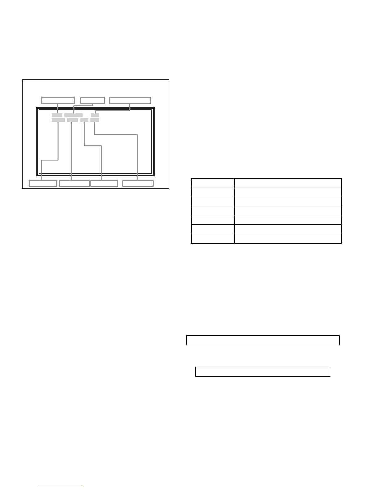
2.1 SYSTEM SETTEING
SERVICE MENU
1. ADJUST
2. SELF CHECK
3. I2C STOP
LOB 0 FAN 0
AUD 0
ANA 9 DIG 9
0000 0
0
SECTION 2
SPECIFIC SERVICE INSTRUCTIONS
Be sure to carry out the following operation at the end of
the procedure.
(1) Set to 0 minutes using the [SLEEP TIMER] key.
(2) Press the [VIDEO STATUS] key and [DISPLAY] key
simultaneously, then enter the SERVICE MODE.
(3) When the Main Menu is displayed, press [2] key to enter
the self check mode.
(4) Turn off the power by pressing the [POWER] key on the
remote control unit.
SERVICE MENU SCREEN
SERVICE MENU
1. ADJUST
2. SELF CHECK
3. I2C STOP
SELF CHECK MODE SCREEN
LOB 0 FAN 0
AUD 0
ANA 9 DIG 9
0000 0
0
2.2 FEATURES
D.I.S.T. (Digital Image Scaling Technology)
This system uses line interpolation to double the number of
scanning lines and achieve high resolution, flicker-free picture.
Color Management
This function ensures dull colors are compensated to produce
natural hues.
Picture Management
This function makes it easier to see the dark areas when a
picture has many dark areas, and makes it easier to see the
bright areas when a picture has many bright areas.
Smart Picture
This function detects the APL (Average Picture Level) and
adjusts the contrast suitable for what you are watching.
DIGITAL VNR
This function cuts down the amount of noise in the original
picture.
MPEG Noise Reduction
This function effects the block noise removal and mosquito NR
simultaneously.
Sensor Effect
With Sensor Effect ON, a "leaf" icon will appear on your TV
screen when Smart Sensor brightness adjustment occurs.
1-6 (No.YA457)
Page 7

2.3 TECHNICAL INFORMATION
2.3.1 LCD PANEL
This unit uses the flat type panel LCD (Liquid Crystal Display) panel that occupies as little space as possible, instead of the
conventional CRT (Cathode Ray Tube), as a display unit.
Since the unit has the two polarizing filter that are at right angles to each other, the unit adopts "normally black" mode, where light
does not pass through the polarizing filter and the screen is black when no voltage is applied to the liquid crystals.
2.3.1.1 SPECIFICATIONS
The following table shows the specifications of this unit.
Item Specifications
Maximum dimensions ( W × H × D ) 87.7 cm × 51.4 cm × 5.6 cm
Weight 8.5 kg
Effective screen size Diagonal: 94.0 cm (H: 82.0 cm × V: 46.1 cm)
Aspect ratio 16 : 9
Drive device / system a-Si-TFT active matrix system
Resolution Horizontally 1366 × Vertically 768 × RGB < W-XGA > 3147264 dots in total
Pixel pitch (pixel size) Horizontally: 0.6 mm, Vertically: 0.6 mm
Displayed colour 16777216 colours 256 colours for R G and B
Brightness 500cd/m2
Contrast ratio 1050 : 1
Response time (Td + Tr) 12 ms
View angle (Horizontally) 176°
View angle (Vertically) 176°
Surface polarizer Anti-Glare type Low reflective coat
Colour filter Vertical stripe
Backlight Cold cathode fluorescent lamp × 18
Power supply voltage in LCD 5 V
Power supply voltage in inverter 24 V
Panel interface system LVDS (Low Voltage Differential Signaling)
2.3.1.2 PIXEL FAULT
There are three pixel faults - bright fault , dark fault and flicker fault - that are respectively defined as follows.
BRIGHT FAULT
In this pixel fault, a cell that should not light originally is lighting on and off.
For checking this pixel fault, input ALL BLACK SCREEN and find out the cell that is lighting on and off.
DARK FAULT
In this pixel fault, a cell that should light originally is not lighting or lighting with the brightness twice as brighter as originally lighting.
For checking this pixel fault, input 100% of each R/G/B color and find out the cell that is not lighting.
FLICKER FAULT
In the pixel fault, a cell that should light originally or not light originally is flashing on and off.
For checking this pixel fault, input ALL BLACK SCREEN signal or 100% of each RGB color and find out the cell that is flashing on
and off.
(No.YA457)1-7
Page 8

2.3.2 MAIN CPU PIN FUNCTION [IC7601
Pin Pin name I/O Function Pin Pin name I/O Function
1 VHOLD1 I Data slice for main screen closed caption 51 P4.3 O Not used
2 HFLT1 I/O LPF for main screen closed caption video input 52 P4.2 O Not used
3 P9.4 O Not used 53 P4.1 O Not used
4 P9.3 O Not used 54 P4.0 O Not used
5 DIGR0 O R [0] for OSD 55 P3.7 O Not used
6 TB1in I AC power for timer clock 56 P3.6 O Not used
7 REMO I Remote control 57 P3.5 O Not used
8 BYTE I Data bus width select [L = 16bit (fixed)] 58 P3.4 O Not used
9 CNVss I CPU programming mode select [Normal = L] 59 P3.3 O Not used
10 DIGG0 O G [0] for OSD 60 P3.2 O Not used
11 DIGB0 O B [0] for OSD 61 P3.1 O Not used
12 RESET I Reset for main CPU [Reset = L] 62 HSYNC I H. sync for OSD
13 Xout O System clock osillation (crystal) : 16MHz 63 P3.0 O Not used
14 Vss - GND 64 VSYNC I V. sync for OSD
15 Xin I System clock osillation (crystal) : 16MHz 65 P2.7 O Not used
16 Vcc1 I 3.3V stand-by power supply 66 P2.6 O Not used
17 OSC1 I Clock for OSD 67 P2.5 O Not used
18 OSC2 O Not used : Clock for OSD 68 P2.4 O Not used
19 INT1 I Not used : AV COMPULINK control 69 P2.3 O Not used
20 INT0 I
21 OUT1 O Ys (blanking) for OSD 71 P2.1 O Clock for Inter IC (serial) bus control
22 OUT2 O YM (transparence) for OSD 72 P2.0 I/O Data for Inter IC (serial) bus control
23 P7.7 O Not used 73 P1.7 O Not used
24 P7.6 O Not used 74 P1.6 O Not used
25 P7.5 O Not used 75 P1.5 O Not used
26 P7.4 O Not used 76 P1.4 O Not used
27 CTA2/RTS2 O Not used 77 P1.3 O Not used
28 CLK2 O Not used 78 P1.2 O Not used
29 RxD2 I Digital tuner control 79 P1.1 O Not used
30 TxD2 O Digital tuner control 80 P1.0 O Function LED lighting
31 SDA2 I/O Not used 81 P0.7 O Communication LED lighting
32 DIGR1 O R [1] for OSD 82 P0.6 O Test point
33 DIGG1 O G [1] for OSD 83 CEC_INT O Not used
34 DIGB1 O B [1] for OSD 84 WAKE O Reset for sub(chassis) CPU
35 TxD0 I Data receive (serial) for external programming 85 CARD_DET I Not used
36 RxD0 O Data transmission (serial) for external programming 86
37 CLK0 I Clock for external programming 87 SDA I/O Data for Inter IC (serial) bus control : memory
38 RTS0 O Busy for external programming [Operation = H] 88 SCL O Clock for Inter IC (serial) bus control : memory
39 P5.7 I Not used 89 DIGR2 O R [2] for OSD
40 P5.6 O Not used 90 DIGG2 O G [2] for OSD
41 HOLD I CPU programming mode select [Normal = H] 91 DIGB2 O B [2] for OSD
42 P5.4 O Not used 92 10.0 O Not used
43 P5.3 O Not used 93 KEY2 I
44 P5.2 O Not used 94 KEY1 I
45 P5.1 O Not used 95 VHOLD2 I Data slice for sub screen closed caption
46 WR O CPU programming mode select [Normal = L] 96 HLF2 I/O LPF for sub screen closed caption video input
47 P4.7 O
48 P4.6 I
49 P4.5 I Clock for sub(chassis) CPU communication (serial) 99 VCCE I 5V stand-by power supply
50 P4.4 O Not used 100 CVIN1 I Video(Y) for main screen closed caption
Request for sub(chassis) CPU communication (serial data)
Data transmission for sub(chassis) CPU communication (serial)
Data receive for sub(chassis) CPU communication (serial)
: DIGITAL PWB]
70 P2.2 O Not used
POWER_SW
97 CVIN2 I Video(Y) for sub screen closed caption
98 TVSETB I Test terminal [L Fixed]
I Power switch (mechanical) detection
Key scan data for front control button (MENU/CH+/CH-) KEY2
Key scan data for front control button (INPUT/VOL+/VOL-) KEY1
1-8 (No.YA457)
Page 9

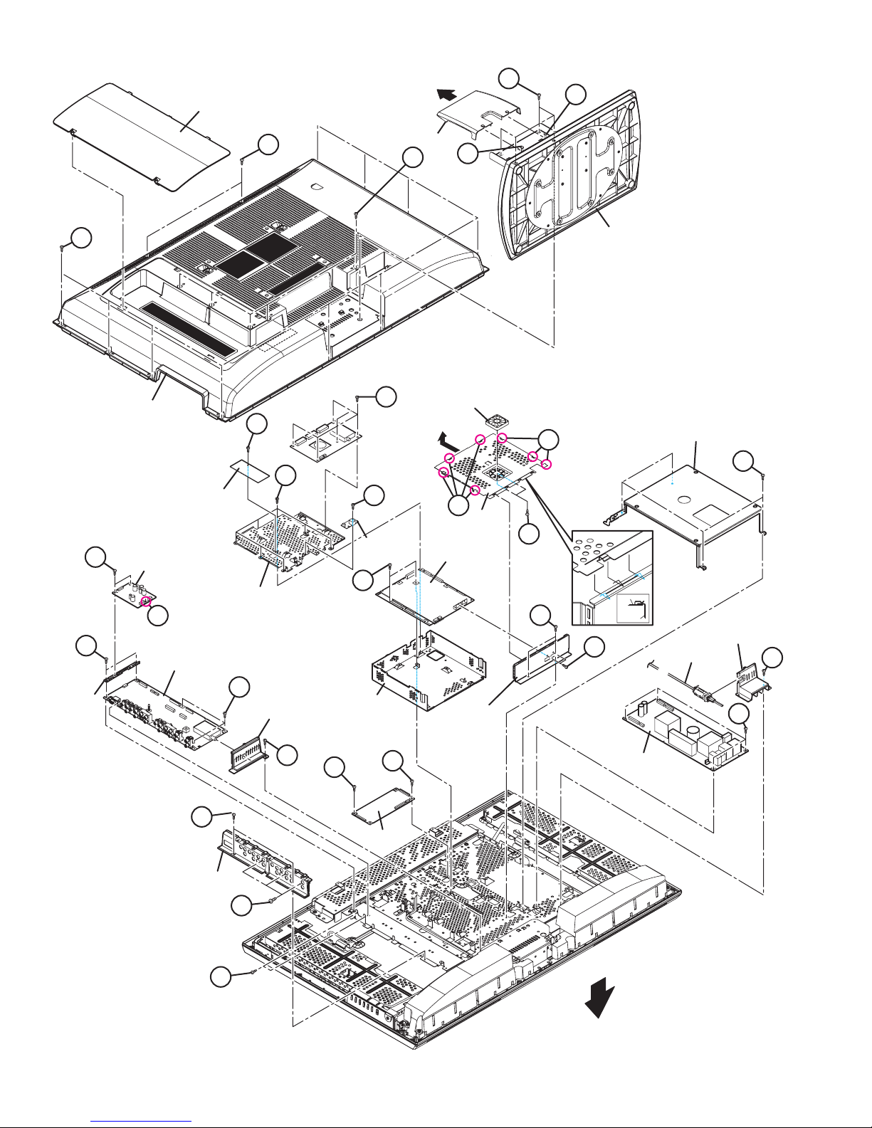
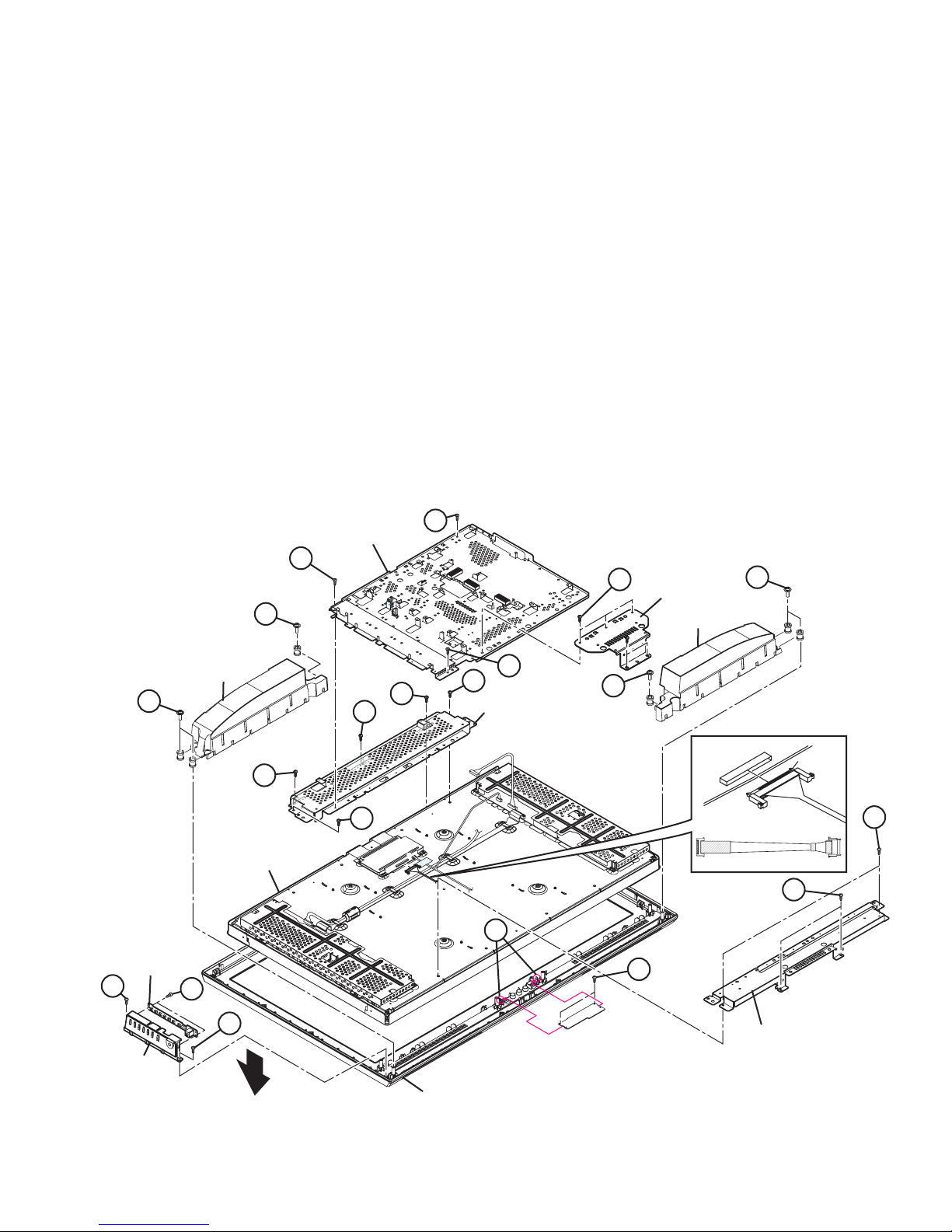
SECTION 3
DISASSEMBLY
3.1 DISASSEMBLY PROCEDURE
CAUTION AT DISASSEMBLY:
• Be sure to perform the SYSTEM SETTEING, at the end of the procedure.
• Make sure that the power cord is disconnected from the outlet.
• Pay special attention not to break or damage the parts.
• When removing each board, remove the connectors as required. Taking notes of the connecting points (connector numbers)
makes service procedure manageable.
• Make sure that there is no bent or stain on the connectors before inserting, and firmly insert the connectors.
3.1.1 REMOVING THE STAND (Fig.1)
(1) Remove the 2 screws [A].
(2) Remove the STAND COVER.
(3) Remove the 4 screws [B].
(4) Remove the STAND.
3.1.2 REMOVING THE REAR COVER (Fig.1)
• Remove the STAND.
(1) Remove the JACK COVER (L/R).
(2) Remove the 10 screws [C], the 5 screws [D], and the 2
screws [E].
(3) Remove the REAR COVER.
3.1.3 REMOVING THE POWER PWB (Fig.1)
• Remove the STAND.
• Remove the REAR COVER.
(1) Remove the 1 screw [F].
(2) Remove the POWER CORD HOLDER.
(3) Remove the POWER CORD.
(4) Remove the 4 screws [G].
(5) Remove the POWER PWB.
3.1.4 REMOVING THE D-AMP PWB (Fig.1)
• Remove the STAND.
• Remove the REAR COVER.
(1) Remove the 2 screw [H] and 1 hook [a].
(2) Remove the D-AMP PWB.
3.1.5 REMOVING THE ANALOG PWB (Fig.1)
• Remove the STAND.
• Remove the REAR COVER.
• Remove the D-AMP PWB.
(1) Remove the 3 screws [J] and 2 screws [K].
(2) Remove the TERMINAL BASE.
(3) Remove the 1 screw [L].
(4) Remove the TUNER BASE.
(5) Remove the 2 screws [M].
(6) Remove the D-AMP BRACKET.
(7) Remove the 3 screws [N].
(8) Remove the 2 screws [P].
(9) Remove the ANALOG PWB.
3.1.6 REMOVING THE DC-DC PWB (Fig.1)
• Remove the STAND.
• Remove the REAR COVER.
(1) Remove the 4 screws [Q].
(2) Remove the BACK BRACKET.
(3) Remove the 2 screws [R].
(4) Remove the DC-DC PWB.
3.1.7 REMOVING THE COOLING FAN (Fig.1)
• Remove the STAND.
• Remove the REAR COVER.
• Remove the BACK BRACKET.
(1) Remove the 7 hooks [b] of the SHIELD COVER.
(2) Remove the SHIELD COVER by sliding it in the direction of
the arrow.
(3) Remove the 2 screws [S].
(4) Remove the COOLING FAN.
3.1.8 REMOVING THE ATSC TUNER MODULE PWB (Fig.1)
• Remove the STAND.
• Remove the REAR COVER.
• Remove the BACK BRACKET.
• Remove the SHIELD COVER.
(1) Remove the 4 screws [T].
(2) Remove the ATSC TUNER MODULE PWB.
3.1.9 REMOVING THE OPTICAL PWB (Fig.1)
• Remove the STAND.
• Remove the REAR COVER.
• Remove the BACK BRACKET.
• Remove the SHIELD COVER.
(1) Remove the 1 screw [U].
(2) Remove the OPTICAL PWB.
3.1.10 REMOVING THE SD CARD PWB (Fig.1)
• Remove the STAND.
• Remove the REAR COVER.
• Remove the BACK BRACKET.
• Remove the SHIELD COVER.
(1) Remove the 1 screw [V].
(2) Remove the SD CARD PWB.
3.1.11 REMOVING THE DIGITAL PWB (Fig.1)
• Remove the STAND.
• Remove the REAR COVER.
• Remove the BACK BRACKET.
• Remove the SHIELD COVER.
• Remove the ATSC TUNER MODULE PWB.
• Remove the SD CARD PWB.
(1) Remove the 2 screws [W] and 2 screws [X].
(2) Remove the SHIELD TERMINAL.
(3) Remove the 7 screws [Y].
(4) Remove the DIGITAL PWB BRACKET.
(5) Remove the 2 screws [Z].
(6) Remove the DIGITAL PWB.
CAUTION :
Make sure to perform the "SYSTEM SETTEING", when
DIGITAL PWB is replaced.
(No.YA457)1-9
Page 10
JACK COVER
B
A
㧯
M
D-AMP PWB
BRACKET
H
REAR COVER
D-AMP PWB
a
ANALOG PWB
SD CARD
PWB
DIGITAL PWB
BRACKET
V
N
TUNER BASE
E
STNAD COVER
D
T
COOLING FAN
A
STNAD
b
BACK BRACKET
Q
Y
U
OPTICAL
PWB
b
SHIELD COVER
DIGITAL PWB
S
Z
SHIELD COVER
SHIELD BASE
X
SHIELD
TERMINAL
W
SHIELD TERMINAL
POWER CORD
POWER CORD HOLDER
F
G
L
K
TERMINAL BASE
J
P
1-10 (No.YA457)
R
R
DC-DC PWB
Fig.1
POWER PWB
FRONT
Page 11
3.1.12 REMOVING THE SW PWB (Fig.2)
• Remove the STAND.
• Remove the REAR COVER.
(1) Remove the 2 screws [A].
(2) Remove the CONTROL ASS’Y with SW PWB.
(3) Remove the 2 screws [B].
(4) Remove the SW PWB from the CONTROL ASS’Y.
3.1.13 REMOVING THE LED PWB (Fig.2)
• Remove the STAND.
• Remove the REAR COVER.
(1) Remove the 3 screws [C].
(2) Remove the STAND BRACKET.
(3) Remove the 2 screws [D] and 2 hooks [a].
(4) Remove the LED PWB.
3.1.14 REMOVING THE SPEAKER (Fig.2)
• Remove the STAND.
• Remove the REAR COVER.
(1) Remove the 6 screws [E].
(2) Remove the SPEAKER (L / R).
NOTE:
• Since the speaker is attached in a certain direction, attach
the speaker in the same correct direction as it has been
attached.
F
MAIN BASE
F
• When the speaker is decomposed, the performance cannot
be kept.
3.1.15 REMOVING THE LCD PANEL UNIT (Fig.2)
• Remove the STAND.
• Remove the REAR COVER.
• Remove the BACK BRACKET.
• Remove the POWER CORD HOLDER.
• Remove the STAND BRACKET.
• Remove the SPEAKER.
(1) Remove the 3 screws [F].
(2) Remove the MAIN BASE.
(3) Remove the 5 screws [H].
(4) Remove the LCD PANEL UNIT with TOP/BOTTOM
FRAME.
(5) Remove the 2 screws [J].
(6) Remove the TOP FARAME from the LCD PANEL UNIT.
(7) Remove the 2 screws [K].
(8) Remove the BOTTOM FARAME from the LCD PANEL UNIT.
C
STAND
BRACKET
E
E
SW PWB
A
CONTROL
ASS'Y
SPEAKER
LCD PANEL UNIT
B
A
E
H
FRONT
SPEAKER
F
H
H
TOP FRAME
J
J
E
The terminal of a connector is turned up and connects.
Surely insert and lock.
Check that connector is inserted completly.
(Don't insert aslant)
"LVDS CABLE"
LCD PANEL SIDE
terminal side
K
DIGITAL PWB SIDE
H
a
D
BOTTOM FRAME
FRONT PANEL
Fig.2
(No.YA457)1-11
Page 12
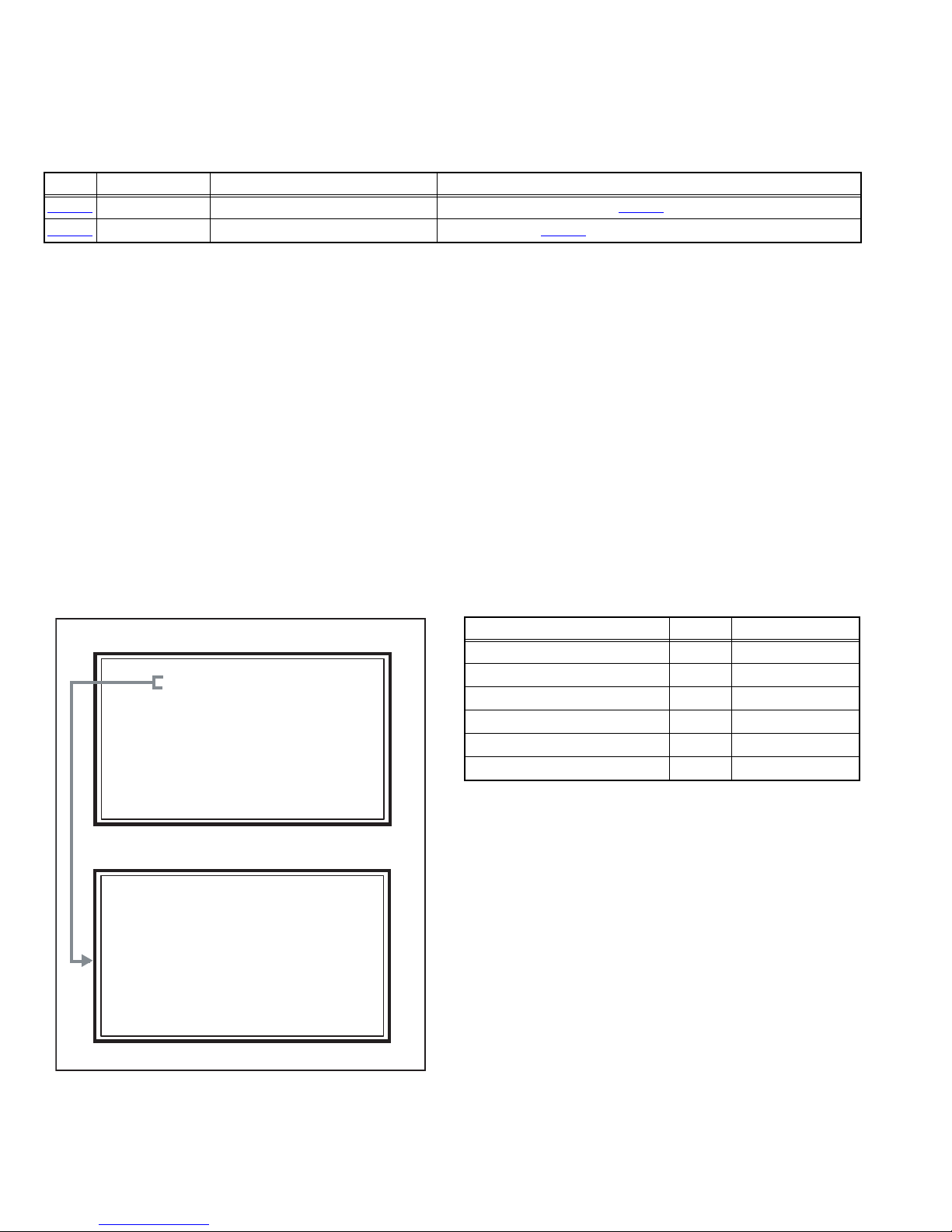
3.2 MEMORY IC REPLACEMENT
S001 R DRIVE 137
NTSC3 FULL STD LOW
SERVICE MENU
1. ADJUST
2. SELF CHECK
3. I2C STOP
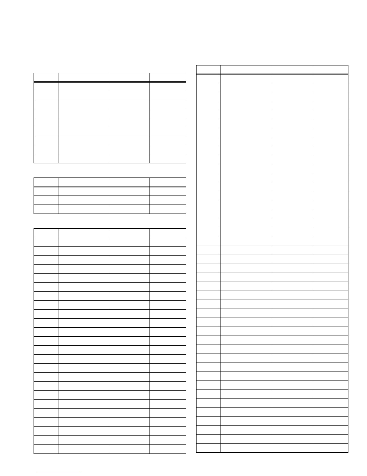
• This model uses the memory IC.
• This memory IC stores data for proper operation of the video and drive circuits.
• When replacing, be sure to use an IC containing this (initial value) data.
3.2.1 MEMORY IC TABLE
Simbol Number of pins Mounting PWB Main content of data
IC7201
IC7602
48-pin DIGITAL PWB Progaram(Video process) of IC6001(System CPU) is memorized.
8-pin DIGITAL PWB Setting value of IC7601(MAIN CPU) is memorized.
3.2.2 MEMORY IC REPLACEMENT PROCEDURE
1. Power off
Switch off the power and disconnect the power plug from the AC outlet.
2. Replace the memory IC
Be sure to use the memory IC written with the initial setting values.
3. Power on
Connect the power plug to the AC outlet and switch on the power.
4. Receiving channel setting
Refer to the OPERATING INSTRUCTIONS and set the receive channels (Channels Preset) as described.
5. User setting
Check the user setting items according to the given in page later. Where these do not agree, refer to the OPERATING
INSTRUCTIONS and set the items as described.
6. SERVICE MODE setting
Verify what to set in the SERVICE MODE, and set whatever is necessary (Fig.1). Refer to the SERVICE ADJUSTMENT for setting.
3.2.3 SERVICE MODE SETTING
SERVICE MODE SCREEN
MAIN MENU SCREEN
SERVICE MENU
1. ADJUST
2. SELF CHECK
3. I2C STOP
ADJUSTMENT MODE SCREEN
S001 R DRIVE 137
NTSC3 FULL STD LOW
SETTING ITEM
Setting items Settings Item No.
Video system setting Adjust S001 - S009
Audio system setting Adjust T001 - T003
Main CPU system setting Fixed M001 - M224
Drive system setting Fixed F001 - F002
(Not used) Fixed D001
(Not used) Fixed Z001
Fig.1
1-12 (No.YA457)
Page 13
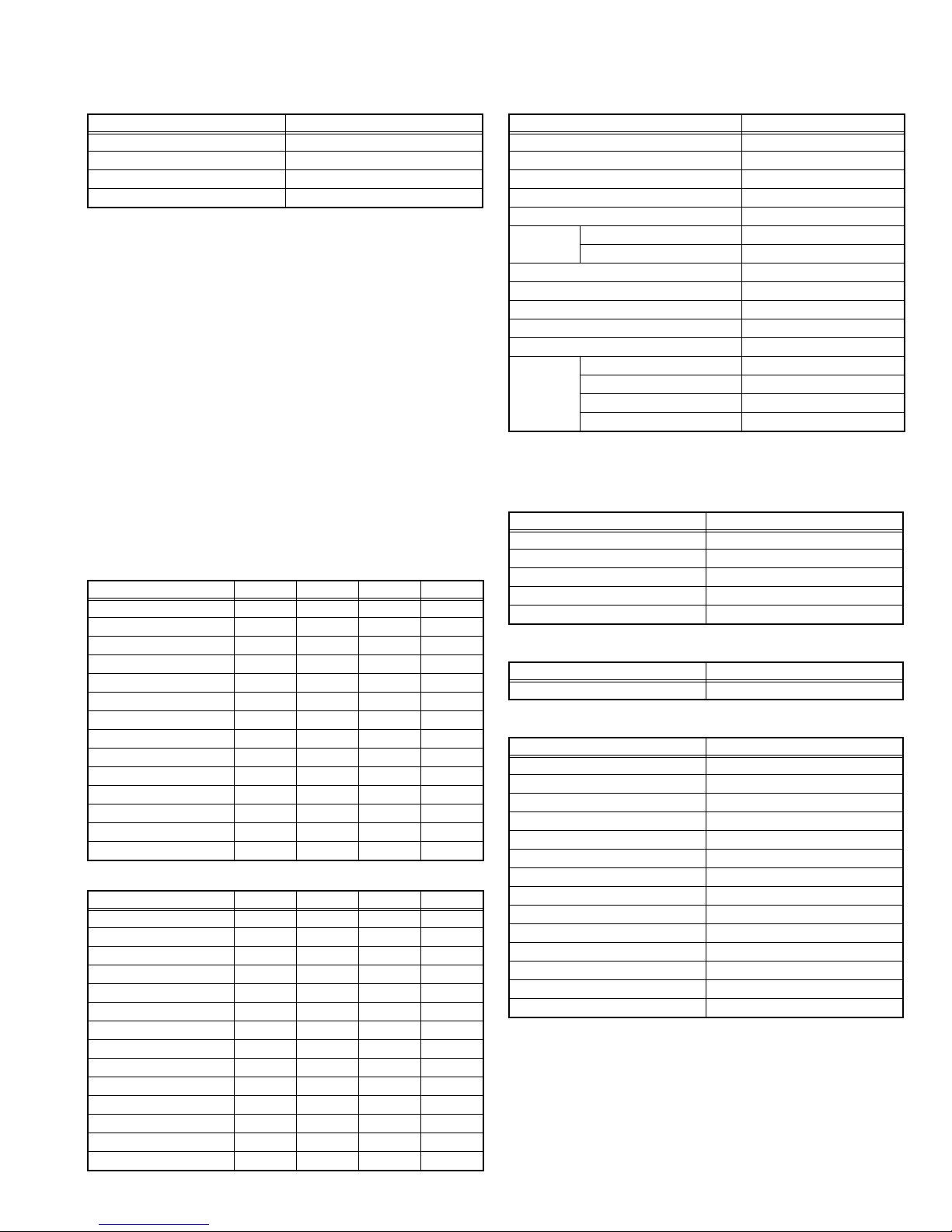
3.2.4 SETTINGS OF FACTORY SHIPMENT
3.2.4.1 BUTTON OPERATION 3.2.4.2 REMOTE CONTROL DIRECT OPERATION
Setting item Setting position
POWER Off
CHANNEL CABLE-02
VOLUME 10
INPUT TV
INPUT TV
CHANNEL CABLE-02
VOLUME 10
MUTING OFF
Setting item Setting position
DISPLAY OFF
ASPECT NTSC PANORAMA
HD / ATSC FULL
SLEEP TIMER OFF
THEATER PRO OFF
NATURAL CINEMA AUTO
VIDEO STATUS DYNAMIC
MTS STEREO
SOUND
EFFECT
A.H.S.+ OFF
VOICE ENHANCEMENT OFF
SMART SOUND OFF
MaxxBass OFF
3.2.4.3 REMOTE CONTROL MENU OPERATION
1. PICTURE ADJUST
Customers can adjust the picture setting of menu screen as their
own like but the picture standard value during factory shipment is as
below.
< NTSC MODE >
Setting item
DYNAMIC
STANDARD
GAME
THEATER
PICTURE +07 00 -10 00
2. SOUND ADJUST
Setting item Setting position
BASS 00
TREBLE 00
BALANCE 00
TURN ON VOLUME Current
VOLUME LIMIT 50
BRIGHT 00 00 00 00
COLOR 00000000
TINT 00 00 00 00
DETAIL +06 00 00 00
ENERGY SAVER MODE
COLOR TEMPERATURE
COLOR MANAGEMENT
+30 +15 00 -25
HIGH LOW HIGH HIGH
ON ON ON ON
DYNAMIC GAMMA ON ON ON ON
SMART PICTURE OFF ON ON ON
DIGITAL VNR AUTO AUTO AUTO AUTO
MPEG NR ON ON ON ON
SMART SENSOR OFF OFF OFF OFF
SENSOR EFFECT OFF OFF OFF OFF
< HD MODE >
Setting item
DYNAMIC
STANDARD
GAME
THEATER
PICTURE +06 00 -10 00
BRIGHT +00 00 00 00
COLOR +00 00 00 00
TINT 00 00 00 00
DETAIL +00 00 00 00
ENERGY SAVER MODE
COLOR TEMPERATURE
COLOR MANAGEMENT
+30 +15 00 -25
HIGH LOW HIGH LOW
ON ON ON ON
3. CLOCK / TIMERS
Setting item Setting position
ON / OFF TIMER OFF
4. INITIAL SETUP
Setting item Setting position
DIGITAL-IN
DIGITAL-IN1 AUDIO
AUTO
AUTO
NOISE MUTING ON
FRONT PANEL LOCK OFF
V1 SMART INPUT OFF
VIDEO INPUT LABEL All blank
POSITION ADJUSTMENT Center
POWER INDICATOR HIGH
LANGUAGE ENG.
CLOSED CAPTION OFF
AUTO SHUT OFF OFF
XDS ID ON
V-CHIP OFF
AUTO DEMO ON
DYNAMIC GAMMA ON ON ON ON
SMART PICTURE OFF ON ON ON
DIGITAL VNR AUTO AUTO AUTO AUTO
MPEG NR ON ON ON ON
SMART SENSOR OFF OFF OFF OFF
SENSOR EFFECT OFF OFF OFF OFF
(No.YA457)1-13
Page 14

3.3 REPLACEMENT OF CHIP COMPONENT
3.3.1 CAUTIONS
(1) Avoid heating for more than 3 seconds.
(2) Do not rub the electrodes and the resist parts of the pattern.
(3) When removing a chip part, melt the solder adequately.
(4) Do not reuse a chip part after removing it.
3.3.2 SOLDERING IRON
(1) Use a high insulation soldering iron with a thin pointed end of it.
(2) A 30w soldering iron is recommended for easily removing parts.
3.3.3 REPLACEMENT STEPS
1. How to remove Chip parts
2. How to install Chip parts
[Resistors, capacitors, etc.]
(1) As shown in the figure, push the part with tweezers and
alternately melt the solder at each end.
(2) Shift with the tweezers and remove the chip part.
[Transistors, diodes, variable resistors, etc.]
(1) Apply extra solder to each lead.
SOLDER
SOLDER
[Resistors, capacitors, etc.]
(1) Apply solder to the pattern as indicated in the figure.
(2) Grasp the chip part with tweezers and place it on the
solder. Then heat and melt the solder at both ends of the
chip part.
[Transistors, diodes, variable resistors, etc.]
(1) Apply solder to the pattern as indicated in the figure.
(2) Grasp the chip part with tweezers and place it on the
solder.
(3) First solder lead A as indicated in the figure.
(2) As shown in the figure, push the part with tweezers and
alternately melt the solder at each lead. Shift and remove
the chip part.
NOTE :
After removing the part, remove remaining solder from the
pattern.
1-14 (No.YA457)
A
B
C
(4) Then solder leads B and C.
A
B
C
Page 15
SECTION 4
SERVICE MENU
1. ADJUST
2. SELF CHECK
3. I2C STOP
ADJUSTMENT
4.1 ADJUSTMENT PREPARATION
(1) There are 2 ways of adjusting this TV : One is with the
REMOTE CONTROL UNIT and the other is the
conventional method using adjustment parts and
components.
(2) The adjustment using the REMOTE CONTROL UNIT is
made on the basis of the initial setting values. The
setting values which adjust the screen to the optimum
condition can be different from the initial setting
values.
(3) Make sure that connection is correctly made AC to AC
power source.
(4) Turn on the power of the TV and measuring instruments for
warning up for at least 30 minutes before starting
adjustments.
(5) If the receive or input signal is not specified, use the most
appropriate signal for adjustment.
(6) Never touch the parts (such as variable resistors,
transformers and condensers) not shown in the adjustment
items of this service adjustment.
4.2 PRESET SETTING BEFORE ADJUSTMENTS
Unless otherwise specified in the adjustment items, preset the
following functions with the REMOTE CONTROL UNIT.
Setting item Settings
VIDEO STATUS STANDARD
BRIGHT / CONTRAST / COLOR / TINT
00
COLOR TEMPERATURE LOW
DIG. NOISE CLEAR OFF
COLOR MANAGEMENT ON
NATURAL CINEMA OFF
TREBLE / BASS / BALANCE 00
SMART SOUND OFF
MTS STEREO
A.H.S.+ OFF
MaxxBass OFF
ASPECT FULL
4.3 MEASURING INSTRUMENT AND FIXTURES
• Signal generator (Pattern generator) [NTSC]
• TV audio multiplex signal generator
• Remote control unit
4.4 ADJUSTMENT ITEMS
VIDEO CIRCUIT
• WHITE BALANCE (HIGHLIGHT) adjustment
MTS CIRCUIT
• MTS INPUT LEVEL adjustment
• MTS SEPARATION adjustment
4.5 BASIC OPERATION OF SERVICE MODE
4.5.1 HOW TO ENTER THE SERVICE MODE
(1) Set to 0 minutes using the [SLEEP TIMER] key.
(2) Press the [VIDEO STATUS] key and [DISPLAY] key
simultaneously, then enter the SERVICE MODE (Fig.1)
SERVICE MENU SCREEN
SERVICE MENU
1. ADJUST
2. SELF CHECK
3. I2C STOP
Fig.1
NOTE:
• Before entering the SERVICE MODE, confirm that the
setting of TV/CATV switch of the REMOTE CONTROL UNIT
is at the "TV" side and the setting of VCR/DVD switch is at
the "VCR" side. If the switches have not been properly set,
you cannot enter the SERVICE MODE.
• When a number key other than the [1] keys is pressed in the
SERVICE MENU SCREEN, the other relevant screen may
be displayed.
This is not used in the adjustment procedure. Press the
[MENU] key to return to the SERVICE MENU SCREEN.
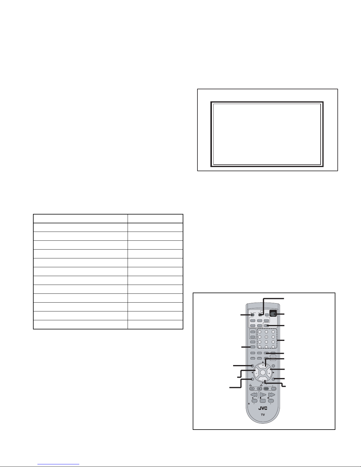
4.5.2 HOW TO EXIT THE SERVICE MODE
Press the [BACK] key to exit the Service mode.
4.5.3 SERVICE MODE SELECT KEY LOCATION
VCR/DVD switch
TV/CATV switch
SLEEP TIMER
MUTING
VOLUME -
MENU
TV
SPLIT
FREEZE
INPUT
D/A
ML/MTS
SLEEP
FAVORITE
C.C.
MUTING
MENU
VCR CHANNEL
PREV NEXT
OPEN CLOSE
CATV VCR DVD
ASPECT
MULTI SCREEN
INDEX
SELECT
SWAP
DISPLAY
1
4
7
TUNE
THEATER
VIDEO
PRO
STATUS
NATURAL
CINEMA
SOUND
CH
VOL VOL
OK
CH
VCR DVD
POWER
REW
PLAY
REC
STOP
RM-C18G
POWER
2
5
8
RETURN+/TV
0
CHANNEL
LIGHT
GUIDE
TV VCR
FF
PAUSE
STILL PAUSE
3
6
9
SUB
BACK
POWER
DISPLAY
NUMBER
VIDEO STATUS
CHANNEL +
VOLUME +
BACK
CHANNEL -
(No.YA457)1-15
Page 16
4.5.4 ADJUSTMENT MODE
S001 R DRIVE 137
NTSC3 FULL STD LOW
This mode is used to adjust the VIDEO CIRCUIT and the MTS CIRCUIT.
4.5.4.1 HOW TO ENTER THE ADJUSTMENT MODE
When the SERVICE MENU SCREEN of SERVICE MODE is displayed, press [1] key to enter the ADJUSTMENT MODE.
4.5.4.2
DESCRIPTION OF STATUS DISPLAY OF ADJUSTMENT MODE
ADJUSTMENT MODE
SETTING ITEM No.
S001 R DRIVE 137
NTSC3 FULL STD LOW
SIGNAL SYSTEM
SCREEN MODE
SETTING ITEM
Fig.2
(1) SIGNAL SYSTEM
The signal displayed on the screen is displayed.
NTSC3 : 525i (Composite / S-video input)
525I : 525i (Component input)
525P : 525p
1125I6 : 1125i
750P : 750p
PCVGA : PC (VGA)
PCXGA : PC (XGA)
H525I : HDMI 525i
H525P : HDMI 525p
H125I6 : HDMI 1125i
H750P : HDMI 750p
D525I : ATSC 525i
D525P : ATSC 525p
D125I6 : ATSC 1125i
(2) SCREEN MODE
State of the SCREEN SIZE or MULTI PICTURE is displayed.
SINGLE SCREEN
FULL : FULL
1609 : CINEMA, CINEMA ZOOM
PANO : PANORAMA, HD PANORAMA
REGU : REGULAR, SLIM
MULTI SCREEN
M2 : SPLIT, FREEZE screen
M12 : INDEX screen
SETTING VALUE (DATA)
VIDEO STATUS
WHITE BALANCE
(3) VIDEO STATUS
STD : STANDARD
DYN : DYNAMIC
TH : THEATER
GAME : GAME
(4) WHITE BALANCE
HIGH : HIGH
LOW : LOW
(5) SETTING ITEM NAME
Setting item name are displayed. The setting item numbers to
be displayed are listed below.
Item No. Setting item
S001 - S009 Video system setting
T001 - T003 Audio system setting
M001 - M224 Main CPU system setting
F001 - F002 Drive system setting
D001 (NOT USED)
Z001 (NOT USED)
(6) SETTING ITEM NO.
Setting item numbers are displayed. For the setting item
names to be displayed, refer to "Initial setting value of
adjustment mode".
(7) SETTING VALUE (DATA)
The SETTING VALUE is displayed.
4.5.4.3 CHANGE AND MEMORY OF SETTING VALUE
SELECTION OF SETTING ITEM
• [CH+] / [CH-] key.
Change the setting items up/ down.
S001... ↔ T001... ↔ M001... ↔ F001... ↔ D001... ↔ Z001...
• [SLEEP TIMER] key.
Switches to the next items.
S001 → T001 → M001... → F001... → D001 → Z001
CHANGE OF SETTING VALUE (DATA)
• [VOL+] / [VOL-] key.
Change the setting values up/down.
MEMORY OF SETTING VALUE (DATA)
Changed setting value is memorized by pressing [MUTING]
key.
1-16 (No.YA457)
Page 17
4.6 INITIAL SETTING VALUES IN THE SERVICE MODE
• Perform fine-tuning based on the "initial values" using the remote control when in the Service mode.
• The "initial values" serve only as an indication rough standard and therefore the values with which optimal display can be achieved
may be different from the default values. But, don't change the values that are not written in "ADJUSTMENT PROCEDURE". They
are fixed values.
4.6.1 VIDEO SYSTEM SETTING
Item No. Item Variable range Setting value
S001 R DRIVE 000 - 255 137
S002 G DRIVE 000 - 255 119
S003 B DRIVE 000 - 255 085
S004 RESREV 000 - 255 000
S005 RESREV 000 - 255 000
S006 RESREV 000 - 255 002
S007 RESREV 000 - 255 002
S008 RESREV 000 - 255 002
S009 RESREV 000 - 255 002
4.6.2 AUDIO SYSTEM SETTING
Item No. Item Variable range Setting value
T001 INPLEVEL 000 - 015 006
T002 LOWSEPA 000 - 063 037
T003 HIGHSEPA 000 - 063 024
4.6.3 MAIN CPU SYSTEM SETTING (Fixed values)
Item No. Item Variable range Setting value
M001 1E00 00 - FF 00
M002 1E01 00 - FF 00
M003 1E02 00 - FF 05
M004 1E03 00 - FF 20
M005 1E04 00 - FF 10
M006 1E05 00 - FF 00
M007 1E06 00 - FF 00
M008 1E07 00 - FF 00
M009 1E08 00 - FF 00
M010 1E09 00 - FF 00
M011 1E0A 00 - FF 01
M012 1E0B 00 - FF 00
M013 1E0C 00 - FF 01
M014 1E0D 00 - FF 00
M015 1E0E 00 - FF 00
M016 1E0F 00 - FF 00
M017 1E10 00 - FF 00
M018 1E11 00 - FF 00
M019 1E12 00 - FF 00
M020 1E13 00 - FF 01
M021 1E14 00 - FF 01
M022 1E15 00 - FF 00
M023 1E16 00 - FF 00
M024 1E17 00 - FF 00
Item No. Item Variable range Setting value
M025 1E18 00 - FF 00
M026 1E19 00 - FF 00
M027 1E1A 00 - FF 00
M028 1E1B 00 - FF 00
M029 1E1C 00 - FF 00
M030 1E1D 00 - FF 00
M031 1E1E 00 - FF 00
M032 1E1F 00 - FF 00
M033 1E20 00 - FF 00
M034 1E21 00 - FF 00
M035 1E22 00 - FF 00
M036 1E23 00 - FF 00
M037 1E24 00 - FF 00
M038 1E25 00 - FF 00
M039 1E26 00 - FF 00
M040 1E27 00 - FF 00
M041 1E28 00 - FF 00
M042 1E29 00 - FF 00
M043 1E2A 00 - FF 00
M044 1E2B 00 - FF 00
M045 1E2C 00 - FF 00
M046 1E2D 00 - FF 00
M047 1E2E 00 - FF 00
M048 1E2F 00 - FF 00
M049 1E30 00 - FF 00
M050 1E31 00 - FF 00
M051 1E32 00 - FF 00
M052 1E33 00 - FF 00
M053 1E34 00 - FF 00
M054 1E35 00 - FF 00
M055 1E36 00 - FF 02
M056 1E37 00 - FF 00
M057 1E38 00 - FF 01
M058 1E39 00 - FF 02
M059 1E3A 00 - FF 10
M060 1E3B 00 - FF 83
M061 1E3C 00 - FF 00
M062 1E3D 00 - FF 00
M063 1E3E 00 - FF 00
M064 1E3F 00 - FF 00
M065 1E40 00 - FF 00
M066 1E41 00 - FF 00
(No.YA457)1-17
Page 18

Item No. Item Variable range Setting value
M067 1E42 00 - FF 00
M068 1E43 00 - FF 03
M069 1E44 00 - FF 03
M070 1E45 00 - FF 03
M071 1E46 00 - FF 3F
M072 1E47 00 - FF 01
M073 1E48 00 - FF 00
M074 1E49 00 - FF 00
M075 1E4A 00 - FF 00
M076 1E4B 00 - FF 00
M077 1E4C 00 - FF 00
M078 1E4D 00 - FF 00
M079 1E4E 00 - FF 00
M080 1E4F 00 - FF 00
M081 1E50 00 - FF 00
M082 1E51 00 - FF 00
M083 1E52 00 - FF 00
M084 1E53 00 - FF 00
M085 1E54 00 - FF 00
M086 1E55 00 - FF 00
M087 1E56 00 - FF 00
M088 1E57 00 - FF 00
M089 1E58 00 - FF 00
M090 1E59 00 - FF 00
M091 1E5A 00 - FF 00
M092 1E5B 00 - FF 00
M093 1E5C 00 - FF 00
M094 1E5D 00 - FF 00
M095 1E5E 00 - FF 00
M096 1E5F 00 - FF 00
M097 1E60 00 - FF 00
M098 1E61 00 - FF 00
M099 1E62 00 - FF 00
M100 1E63 00 - FF 00
M101 1E64 00 - FF 00
M102 1E65 00 - FF 00
M103 1E66 00 - FF 00
M104 1E67 00 - FF 00
M105 1E68 00 - FF 04
M106 1E69 00 - FF 03
M107 1E6A 00 - FF 02
M108 1E6B 00 - FF 00
M109 1E6C 00 - FF 00
M110 1E6D 00 - FF 00
M111 1E6E 00 - FF 00
M112 1E6F 00 - FF 00
Item No. Item Variable range Setting value
M113 1E70 00 - FF 00
M114 1E71 00 - FF 00
M115 1E72 00 - FF 00
M116 1E73 00 - FF 00
M117 1E74 00 - FF 00
M118 1E75 00 - FF 00
M119 1E76 00 - FF 00
M120 1E77 00 - FF 0F
M121 1E78 00 - FF 13
M122 1E79 00 - FF 00
M123 1E7A 00 - FF 00
M124 1E7B 00 - FF 00
M125 1E7C 00 - FF 00
M126 1E7D 00 - FF 00
M127 1E7E 00 - FF 01
M128 1E7F 00 - FF 00
M129 1E80 00 - FF 01
M130 1E81 00 - FF 00
M131 1E82 00 - FF 01
M132 1E83 00 - FF 00
M133 1E84 00 - FF 00
M134 1E85 00 - FF 00
M135 1E86 00 - FF 00
M136 1E87 00 - FF 00
M137 1E88 00 - FF 00
M138 1E89 00 - FF 00
M139 1E8A 00 - FF 00
M140 1E8B 00 - FF 00
M141 1E8C 00 - FF 00
M142 1E8D 00 - FF 00
M143 1E8E 00 - FF 00
M144 1E8F 00 - FF 00
M145 1E90 00 - FF 00
M146 1E91 00 - FF 00
M147 1E92 00 - FF 00
M148 1E93 00 - FF 00
M149 1E94 00 - FF 00
M150 1E95 00 - FF 00
M151 1E96 00 - FF 00
M152 1E97 00 - FF 00
M153 1E98 00 - FF 00
M154 1E99 00 - FF 00
M155 1E9A 00 - FF 01
M156 1E9B 00 - FF 00
M157 1E9C 00 - FF 03
M158 1E9D 00 - FF 00
1-18 (No.YA457)
Page 19
Item No. Item Variable range Setting value
M159 1E9E 00 - FF 00
M160 1E9F 00 - FF 00
M161 1EA0 00 - FF 00
M162 1EA1 00 - FF 00
M163 1EA2 00 - FF 01
M164 1EA3 00 - FF 00
M165 1EA4 00 - FF 00
M166 1EA5 00 - FF 00
M167 1EA6 00 - FF 00
M168 1EA7 00 - FF 00
M169 1EA8 00 - FF 00
M170 1EA9 00 - FF 00
M171 1EAA 00 - FF 00
M172 1EAB 00 - FF 00
M173 1EAC 00 - FF 0A
M174 1EAD 00 - FF 00
M175 1EAE 00 - FF 00
M176 1EAF 00 - FF 00
M177 1EB0 00 - FF 00
M178 1EB1 00 - FF 00
M179 1EB2 00 - FF 01
M180 1EB3 00 - FF 00
M181 1EB4 00 - FF 00
M182 1EB5 00 - FF 00
M183 1EB6 00 - FF 00
M184 1EB7 00 - FF 00
M185 1EB8 00 - FF 00
M186 1EB9 00 - FF 00
M187 1EBA 00 - FF 00
M188 1EBB 00 - FF 00
M189 1EBC 00 - FF 00
M190 1EBD 00 - FF 00
M191 1EBE 00 - FF 00
M192 1EBF 00 - FF 00
M193 1EC0 00 - FF 00
M194 1EC1 00 - FF 00
M195 1EC2 00 - FF 01
M196 1EC3 00 - FF 00
M197 1EC4 00 - FF 00
M198 1EC5 00 - FF 00
M199 1EC6 00 - FF 00
M200 1EC7 00 - FF 00
M201 1EC8 00 - FF 01
M202 1EC9 00 - FF 00
M203 1ECA 00 - FF 00
M204 1ECB 00 - FF 00
Item No. Item Variable range Setting value
M205 1ECC 00 - FF 02
M206 1ECD 00 - FF 00
M207 1ECE 00 - FF 00
M208 1ECF 00 - FF 00
M209 1ED0 00 - FF 10
M210 1ED1 00 - FF 00
M211 1ED2 00 - FF 00
M212 1ED3 00 - FF 00
M213 1ED4 00 - FF 00
M214 1ED5 00 - FF 00
M215 1ED6 00 - FF 00
M216 1ED7 00 - FF 00
M217 1ED8 00 - FF 00
M218 1ED9 00 - FF 00
M219 1EDA 00 - FF 00
M220 1EDB 00 - FF 00
M221 1EDC 00 - FF 00
M222 1EDD 00 - FF 00
M223 1EDE 00 - FF 00
M224 1EDF 00 - FF 00
4.6.4 DRIVE SYSTEM SETTING (Fixed values)
Item No. Item Variable range Setting value
F001 DD 000 - 001 000
F002 RAM REF 000 - 001 000
4.6.5 NOT USED (Fixed values)
Item No. Item Variable range Setting value
D001 RESREV 000 - 255 002
4.6.6 NOT USED (Fixed values)
Item No. Item Variable range Setting value
Z001 RESREV 000 - 255 002
(No.YA457)1-19
Page 20
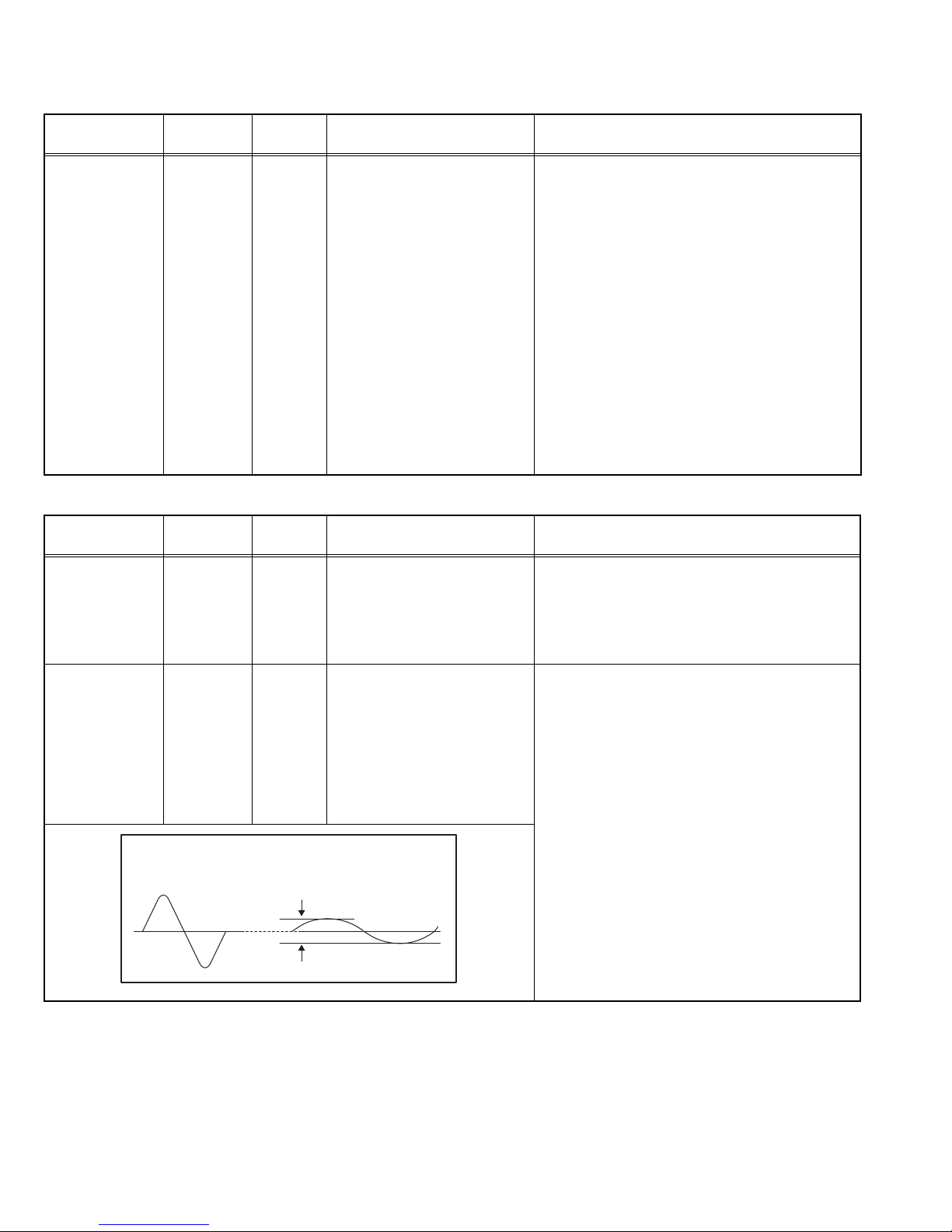
4.7 ADJUSTMENT PROCEDURE
4.7.1 VIDEO CIRCUIT
Item
WHITE
BALANCE
Measuring
instrument
Remote
control unit
Test point Adjustment part Description
(HIGHLIGHT)
Signal
generator
4.7.2 MTS CIRCUIT
Item
MTS INPUT
LEVEL
MTS
SEPARATION
Measuring
instrument
Remote
control unit
TV audio
multiplex
Test point Adjustment part Description
L OUT
R OUT
signal
generator
Oscilloscope
Remote
control unit
L-Channel
signal waveform
1 cycle
[1.ADJUST]
S030: R DRIVE (Red drive)
S031: G DRIVE (Green drive)
S032: B DRIVE (Blue drive)
[1.ADJUST]
T001: IN LEVEL
[1.ADJUST]
T002: LOW SEP
T003: HI SEP
R-Channel
crosstalk portion
Minimum
(1) Receive a NTSC 75% all white signal.
(2) Set "VIDEO STATUS" to "STANDARD".
(3) Set "ASPECT" to "FULL".
(4) Select "COLOR TEMPERATURE" to "LOW".
(5) Select "1.ADJUST" from the SERVICE MODE.
(6) Adjust to keep one of <S030> (Red drive),
<S031> (Green drive) or <S032> (Blue drive)
unchanged, then lower the other two so that the
all-white screen is equally white throughout.
NOTE:
Set one or more of <S030>, <S031>, and
<S032 > to "137".
(7) Check that white balance is properly tracked
from low light to high light. If the white balance
tracking is deviated, adjust to correct it.
(8) Press the [MUTING] key to memoirze the set
value.
(1) Receive the any broadcast.
(2) Select "1.ADJUST" from the SERVICE MODE.
(3) Verify that the <T001> (IN LEVEL) is set at its
initial setting value.
(4) Press the [MUTING] key to memorize the set
value.
(1) Input the stereo L signal (300Hz) from the TV
audio multiplex signal generator to the antenna
terminal.
(2) Connect an oscilloscope to L OUT pin of the
AUDIO OUT, and display one cycle portion of
the 300Hz signal.
(3) Change the connection of the oscilloscope to
R OUT pin of the AUDIO OUT, and enlarge the
voltage axis.
(4) Select "1.ADJUST" from the SERVICE MODE.
(5) Set the initial setting value of the <T002>
(LOW SEP).
(6) Adjust the <T002> so that the stroke element
of the 300Hz signal will become minimum.
(7) Change the signal to 3kHz, and similarly ad-
just the <T003> (HI SEP).
(8) Press the [MUTING] key to memorize the set
value.
1-20 (No.YA457)
Page 21

SECTION 5
SERVICE MENU
1. ADJUST
2. SELF CHECK
3. I2C STOP
TMP 0 L 1 0
L 2 0 DDT 0
FAN 0 L C 0
IRS 0
LOB 0 FAN 0
AUD 0
ANA 9 DIG 9
0000 0
0
TROUBLESHOOTING
5.1 SELF CHECK FEATURE
5.1.1 OUTLINE
This unit comes with the "Self check" feature, which checks the
operational state of the circuit and displays/saves it during
failure.Diagnosis is performed when power is turned on, and
information input to the main microcomputer is monitored at all
time. Diagnosis is displayed in 2 ways via screen display and
LED flashes. Failure detection is based on input state of I
and the various control lines connected to the main
microcomputer.
5.1.2 HOW TO ENTER THE SELF CHECK MODE
Before entering the Self check Display mode, confirm that the
setting of TV/CATV SW of the REMOTE CONTROL UNIT is at
the "TV" side and the setting of VCR/DVD SW is at the "VCR"
side. If the switches have not been properly set, you cannot enter
the Self check Display mode.
(1) Set to "0 minutes" using the [SLEEP TIMER] key.
(2) Press the [VIDEO STATUS] key and [DISPLAY] key
simultaneously, then enter the service mode.
(3) Press the [2] key (SELF CHECK) before the service mode
screen disappears.
(4) Press the [SLEEP TIMER] key to enter Page 2 of the SELF
CHECK MODE.
• When the [RETURN+] key pressed, the first page
change screen.
NOTE:
When a number key other than the [2] key is pressed in
the SERVICE MENU SCREEN, the other relevant
screen may be displayed.
This is not used in the SELF CHECK. Press the [MENU]
key to return to the SERVICE MENU SCREEN.
5.1.3 HOW TO EXIT THE SELF CHECK MODE
TO SAVE FAILURE HISTORY:
Turn off the power by unplugging the AC power cord plug when
in the Self check display mode.
TO CLEAR (RESET) FAILURE HISTORY:
Turn off the power by pressing the [POWER] key on the remote
control unit when in the Self check display mode.
2
C bus
5.1.5 POINTS TO NOTE WHEN USING THE SELF CHECK
FEATURE
In addition to circuit failures (abnormal operation), the following
cases may also be diagnosed as "Abnormal" and displayed and
counted as "NG".
(1) Temporary defective transmissions across circuits due to
pulse interruptions
(2) Misalignment in the on/off timing of power for I
2
C bus
(VCC) when turning on/off the main power.
Diagnosis may be impeded if a large number of items are
displayed as "NG". As such, start Self check check only after 3
seconds in the case of receivers and 5 seconds in the case of
panels upon turning on the power. If recurrences are expected,
ensure to clear (reset) the failure history and record the new
diagnosis reults.
SERVICE MENU SCREEN
SERVICE MENU
1. ADJUST
2. SELF CHECK
3. I2C STOP
SELF CHECK MODE SCREEN (Page 1)
LOB 0 FAN 0
AUD 0
ANA 9 DIG 9
0000 0
0
Item Failure history
5.1.4 FAILURE HISTORY
Failure history can be counted up to 9 times for each item. When
the number exceeds 9, display will remain as 9. Failure history
will be stored in the memory unless it has been deleted.
NOTE:
Only SYNC (with/without sync signals) will be neither counted
nor stored.
SELF CHECK MODE SCREEN (Page 2)
TMP 0 L 1 0
L 2 0 DDT 0
FAN 0 L C 0
IRS 0
Item
Fig.1
Failure history
(No.YA457)1-21
Page 22
5.1.6 DETAILS
Self check is performed for the following items:
< Page 1 of screen >
Detection item Display Detection content
Low bias line short
protection
LOB Confirm the operation of the low bais (16V / 5V /
LCD5V / 3.3V / 1.2V) protection circuit.
Q9601, Q9651[POWER PWB]
Diagnosis
signal (line)
Detection timing
LB_PRO Detection starts 3 seconds after
the power is turned on. If error
continues between 200 ms the
power is turned off.
Fan lock FAN Not used ---- ----
Audio AUD Not used ---- ----
Devices on the ANALOG
PWB
Devices on the DIGITAL
PWB
ANA Confirmation of reply of ACK signal which uses
I2C communication.
, IC102, IC381, IC601, IC606, TU3001
IC101
[ANALOG PWB]
DIG Confirmation of reply of ACK signal which uses
I2C communication. [DIGITAL PWB]
SDA If it checks whenever I2C
communication is performed and
no reply of ACK signal an error
will be counted.
SDA If it checks whenever I2C
communication is performed and
no reply of ACK signal an error
will be counted.
< Page 2 of screen >
Detection item Display Detection content
Diagnosis
signal (line)
Detection timing
Temp. sensor TEM Not used ---- ----
Lamp does not light up L1 Not used ---- ----
Lamp goes out L2 Not used ---- ----
Abnormal DD CPU circuit
DDT Not used ---- ----
Fan lock FAN Not used ---- ----
Lamp cover open LC Not used ---- ----
Abnormal of optical iris IRS Not used ---- ----
5.1.7 METHOD OF DISPLAY WHEN A RASTER IS NOT OUTPUT
In the state where a raster is not output by breakdown of the set, an error is displayed by blink of the POWER LED.
Type of error POWER LED flash cycle
Low bias line short protection Blue LED turnig on and off at 1 second intervals.
ATSC TUNER fan lock detection Blue LED turnig on and off at 2 second intervals.
< Explanation of operation >
If error is detected, the power is turned off.
Shortly after a power is turned off, POWER LED will be blinked.
Power cannot be turned on until the power cord takes out and inserts, after a power is turned off.
1-22 (No.YA457)
Page 23

Victor Company of Japan, Limited
Display Category 12, 3-chome, Moriya-cho, Kanagawa-ku, Yokohama-city, Kanagawa-prefecture, 221-8528, Japan
(No.YA457)
Printed in Japan
VPT
Page 24
LCD Flat Television Users Guide
For Model:
LT-37X987
Important Note:
In the spaces below, enter the model and serial number of your television (located at the
rear of the television cabinet). Staple your sales receipt or invoice to the inside cover of this
guide. Keep this user’s guide in a convenient place for future reference. Keep the carton
and original packaging for future use.
Model Number:
Serial Number:
Illustration of LT-37X987 and RM-C18G
LCT2158-001A-A
0606TNH-II-IM
Page 25
Important Safety Precautions
CAUTION
RISK OF ELECTRIC SHOCK
DO NOT OPEN
CAUTION: To reduce the risk of electric shock. Do not
remove cover (or back). No user serviceable
parts inside. Refer servicing to qualified service
personnel.
The lightning flash with arrowhead symbol, within an
equilateral triangle is intended to alert the user to the
presence of uninsulated “dangerous voltage” within
the product’s enclosure that may be of sufficient
magnitude to constitute a risk of electric shock to
persons.
The exclamation point within an equilateral triangle is
intended to alert the user to the presence of important
operating and maintenance (servicing) instructions in
the literature accompanying the appliance.
WARNING: TO PREVENT FIRE OR SHOCK HAZARDS, DO NOT EXPOSE THIS
APPARATUS TO RAIN OR MOISTURE.
CAUTION: TO INSURE PERSONAL SAFETY, OBSERVE THE FOLLOWING RULES
REGARDING THE USE OF THIS UNIT.
1. Operate only from the power source specified on the unit.
2. Avoid damaging the AC plug and power cord.
3. Avoid Improper installation and never position the unit where good ventilation is unattainable.
4. Do not allow objects or liquid into the cabinet openings.
5. In the event of trouble, unplug the unit and call a service technician. Do not attempt to repair
it yourself or remove the rear cover.
Changes or modifications not approved by JVC could void the warranty.
* When you don’t use this TV set for a long period of time, be sure to disconnect both the
power plug from the AC outlet and antenna for your safety.
* To prevent electric shock do not use this polarized plug with an extension cord, receptacle or
other outlet unless the blades can be fully inserted to prevent blade exposure.
IMPORTANT RECYCLING INFORMATION
This product has a fluorescent lamp that contains a small amount of mercury. It also
contains lead in some components. Disposal of the materials may be regulated in your
community due to environmental considerations. For disposal or recycling information,
please contact your local authorities, or the Electronic Industries Alliance:
http://www.eiae.org
2
Page 26

• As an “ENERGY STAR®” partner,
JVC has determined that this
product or product model meets the
“ENERGY STAR
efficiency.
®
” guidelines for energy
IMPORTANT SAFETY INSTRUCTIONS
1) Read these instructions.
2) Keep these instructions.
3) Heed all warnings.
4) Follow all instructions.
5) Do not use this apparatus near water.
6) Clean only with dry cloth.
7) Do not block any ventilation openings. Install in accordance with the manufacturer's
instructions.
8) Do not install near any heat sources such as radiators, heat registers, stoves, or other
apparatus (including amplifiers) that produce heat.
9) Do not defeat the safety purpose of the polarized or grounding-type plug. A polarized plug
has two blades with one wider than the other. A grounding type plug has two blades and
a third grounding prong. The wide blade or the third prong are provided for your safety. If
the provided plug does not fit into your outlet, consult an electrician for replacement of the
obsolete outlet.
10) Protect the power cord from being walked on or pinched particularly at plugs, convenience
receptacles, and the point where they exit from the apparatus.
11) Only use attachments/accessories specified by the manufacturer.
12) Use only with a cart, stand, tripod, bracket, or table specified by the manufacturer, or sold
with the apparatus. When a cart is used, use caution when moving the cart/apparatus
combination to avoid injury from tip-over.
3
Page 27
13) Unplug this apparatus during lightning storms or when unused for long periods of time.
14) Refer all servicing to qualified service personnel. Servicing is required when the apparatus has
been damaged in any way, such as power-supply cord or plug is damaged, liquid has been
spilled or objects have fallen into the apparatus, the apparatus has been exposed to rain or
moisture, does not operate normally, or has been dropped.
15) Apparatus shall not be exposed to dripping or splashing and no objects filled with liquids, such as
vases, shall be placed on the apparatus.
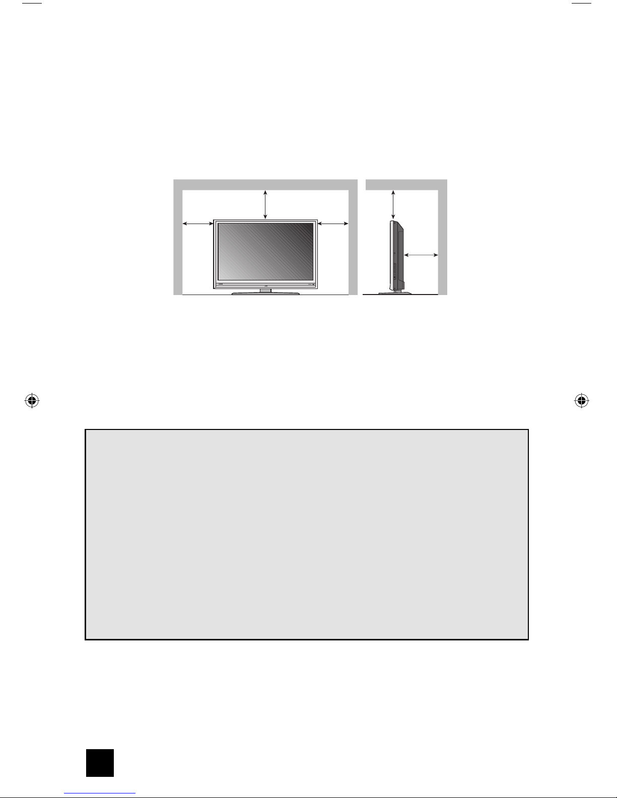
16) Avoid improper installation and never position the unit where good ventilation is impossible. When
installing this TV, distance recommendations must be maintained between the set and the wall,
as well as inside a tightly enclosed area or piece of furniture. Keep to the minimum distance
guidelines shown for safe operation.
150 mm
200 mm
150 mm
POWER
200 mm
50 mm
17) Cautions for installation
— Do not tilt the TV towards the left or right, or towards the back.
— Install the TV in a corner on the floor so as to keep cords out of the way.
— The TV will generate a slight amount of heat during operation. Ensure that sufficient space is
available around the TV to allow satisfactory cooling.
18) Make enough room for inserting and removing the power plug. Place the TV as close to the
outlet as possible. The main power supply for this TV is controlled by inserting or removing the
power plug.
FCC Notice:
Note: This equipment has been tested and found to comply with the limits for a Class B
digital device, pursuant to Part 15 of the FCC Rules. These limits are designed to provide
reasonable protection against harmful interference in a residential installation. This
equipment generates, uses and can radiate radio frequency energy and, if not installed
and used in accordance with the instructions, may cause harmful interference to radio
communications. However, there is no guarantee that interference will not occur in a
particular installation. If this equipment does cause harmful interference to radio or television
reception, which can be determined by turning the equipment off and on, the user is
encouraged to try to correct the interference by one or more of the following measures:
– Reorient or relocate the receiving antenna.
– Increase the separation between the equipment and receiver.
– Connect the equipment into an outlet on a circuit different from that to which the receiver is
connected.
– Consult the dealer or an experienced radio/TV technician for help.
4
Page 28
Warnings
We have an important note for customers who subscribe to basic cable services (do not have
a separate cable box) and plan to use their JVC TV remote control to select channels.
Once you run the Auto Tuner Setup (which detects and programs all the channels your TV is
receiving through the RF input), every channel number available from your cable company
will appear in your television’s Channel Summary and they will all be marked as available for
scanning. Even though every channel is detected and appears as available, you will only be
able to view those that you specifi cally subscribe to from your cable company. This will likely
mean there are blank channels between those channels you wish to scan or “surf”.
We apologize for any inconvenience this may cause but it is important to note that this is
not a malfunction of your television. If you want to sequentially scan those channels you
subscribe to without blank ones in between, you can contact your cable company for their
cable box and remote.
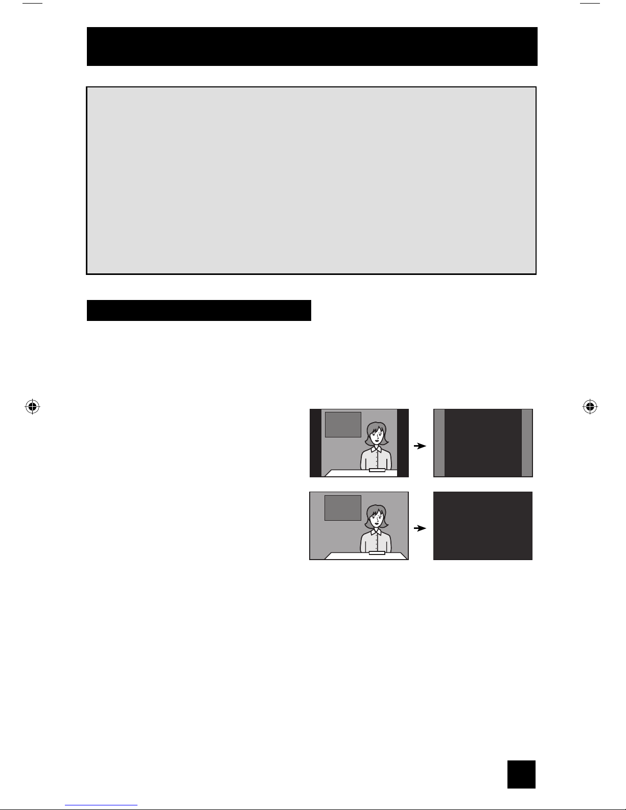
Avoiding Ghost Images
Displaying fi xed images for extended periods of time can leave a subtle but temporary ghost
image on your screen. To avoid this, mix your viewing pattern.
Examples include, but are not limited to the following:
• Stock-market report bars
• Shopping channel logos and pricing
displays
• Video game patterns or scoreboards
• Bright station logos
• Internet web sites or other computer-style
images.
• DVD discs, video tapes, laser discs
• Broadcast, cable, satellite channels or
digital television tuners/converters.
TV on
For example...
TV off
XYZ XYZ
5
Page 29

Warnings (Continued...)
Caring for the Cabinet
Normally, light dusting with a soft, non-scratching duster will keep your TV clean.
If you wish to wipe down the television, first unplug it. Then wipe gently with a soft cloth, slightly
moistened with water. You can add a few drops of mild liquid detergent to the water to help
remove spots of oily dirt.
• DO NOT allow liquid to enter the TV through the ventilation slots.
• DO NOT use strong or abrasive cleaners on the TV.
• DO NOT spray liquids or cleaners directly on the TV’s surface.
• DO NOT rub or scrub the TV harshly. Wipe the set gently with a soft cloth.
Caring for the Screen
The screen is treated with an electrostatic-proof coating. When it gets dirty, wipe it gently with a
soft cloth. If the screen is very dirty, wipe it down with a cloth dipped in a diluted kitchen cleaner
and thoroughly wrung-out. Then wipe immediately after with a clean, dry cloth.
Do not apply alcohol, organic solvents (like acetone), acidic or alkaline cleansers to the screen.
These will remove the coating layer and cause discolorations.
Do not push or hit the screen. This could cause scratches on the screen surface and image
distortions.
6
Page 30

Table of Contents
Important Safety Precautions . . 2
Warnings . . . . . . . . . . . . . . . 5
Quick Setup . . . . . . . . . . . . . . 8
Unpacking your TV . . . . . . . . . . . . 8
Using the stand . . . . . . . . . . . . . . . 8
TV Models . . . . . . . . . . . . . . . . 9
TV Remote Control . . . . . . . . . . . 10
Getting Started . . . . . . . . . . . . . 11
The Remote Control . . . . . . . . . . 11
Connecting Your Devices . . . . . . . 12
Interactive Plug In Menu . . . . . . . . 24
Programming your remote . . . . . . . 27
Onscreen Menus . . . . . . . . . 31
Using the Guide . . . . . . . . . . . . . 31
Onscreen Menu System . . . . . . . . . 32
Initial Setup . . . . . . . . . . . . . 34
Auto Tuner Setup . . . . . . . . . . . . 34
Channel Summary . . . . . . . . . . . . 35
Channel Label . . . . . . . . . . . . . 36
V-Chip . . . . . . . . . . . . . . . . . . 37
Set Lock Code . . . . . . . . . . . . . 43
Auto Demo . . . . . . . . . . . . . . . . 44
Language . . . . . . . . . . . . . . . . 44
Closed Caption . . . . . . . . . . . . . 45
Auto Shut Off . . . . . . . . . . . . . . 47
XDS ID . . . . . . . . . . . . . . . . . 47
Noise Muting . . . . . . . . . . . . . . 48
Front Panel Lock . . . . . . . . . . . . 48
V1 Smart Input . . . . . . . . . . . . 49
Video Input Label . . . . . . . . . . 50
Position Adjustment . . . . . . . . . . . 51
Power Indicator . . . . . . . . . . . . . 51
Digital-In . . . . . . . . . . . . . . . 52
Digital-In1 Audio . . . . . . . . . . . 52
Digital Setup . . . . . . . . . . . . . 53
Picture Adjust . . . . . . . . . . . . . 55
Picture Settings . . . . . . . . . . . . . 55
Color Temperature . . . . . . . . . . . . 55
Color Management . . . . . . . . . . . . 56
Dynamic Gamma . . . . . . . . . . . . . 56
Smart Picture . . . . . . . . . . . . . . . 56
Digital VNR . . . . . . . . . . . . . . . . 57
MPEG NR . . . . . . . . . . . . . . . 57
Smart Sensor . . . . . . . . . . . . . . . 57
Sensor Effect . . . . . . . . . . . . . . . 58
Reset . . . . . . . . . . . . . . . . . . 58
Sound Adjust . . . . . . . . . . . . . 59
Sound Settings . . . . . . . . . . . . . 59
Turn On Volume . . . . . . . . . . . . . 59
Volume Limit . . . . . . . . . . . . . . 59
Reset . . . . . . . . . . . . . . . . . . 59
Clock/Timers . . . . . . . . . . . . . . . . 60
Set Clock . . . . . . . . . . . . . . . . 60
On/Off Timer . . . . . . . . . . . . . . . 61
Button Functions . . . . . . . . . . 62
Multi Screen Function . . . . . . . . . . 62
Split . . . . . . . . . . . . . . . . . . 62
Index . . . . . . . . . . . . . . . . . 63
Freeze . . . . . . . . . . . . . . . . . . 63
Swap . . . . . . . . . . . . . . . . . 63
Select . . . . . . . . . . . . . . . . . . 63
Menu . . . . . . . . . . . . . . . . . . 63
OK . . . . . . . . . . . . . . . . . . . 63
Back . . . . . . . . . . . . . . . . . . . 63
Power . . . . . . . . . . . . . . . . . . 64
Number Buttons . . . . . . . . . . . . . 64
Tune . . . . . . . . . . . . . . . 64
Input . . . . . . . . . . . . . . . . . . . 64
TheaterPro . . . . . . . . . . . . . . . 64
Return+/TV . . . . . . . . . . . . . . . 65
Sound . . . . . . . . . . . . . . . . . . 65
Video Status . . . . . . . . . . . . . . . 66
Natural Cinema . . . . . . . . . . . . . 66
Sleep Timer . . . . . . . . . . . . . . . 67
ML/MTS . . . . . . . . . . . . . . . . . 67
Muting . . . . . . . . . . . . . . . . . . 67
Display . . . . . . . . . . . . . . . . . 68
C.C. . . . . . . . . . . . . . . . . . . . 68
Channel +/- . . . . . . . . . . . . . 68
Volume +/- . . . . . . . . . . . . . 68
Favorite . . . . . . . . . . . . . . . . 69
Aspect . . . . . . . . . . . . . . . . . 70
Aspect Ratios . . . . . . . . . . . . . 70
TV/CATV Slide Switch . . . . . . . . . . 72
VCR/DVD Slide Switch . . . . . . . . . 72
VCR Buttons . . . . . . . . . . . . . . . 72
DVD Buttons . . . . . . . . . . . . . . . 72
Light . . . . . . . . . . . . . . . . . . 72
D/A (Digital/Analog) . . . . . . . . . 73
Sub Channel . . . . . . . . . . . . . 73
Guide . . . . . . . . . . . . . . . 73
OSD Information . . . . . . . . . . 74
Weak Signal . . . . . . . . . . . . . 74
No Program . . . . . . . . . . . . . 74
Invalid Signal . . . . . . . . . . . . . 74
Troubleshooting . . . . . . . . . . 75
Specifications . . . . . . . . . . 77
Warranty . . . . . . . . . . . . . 78
Authorized Service Center . . . 79
7
Page 31

Quick Setup
Unpacking your TV
Thank you for your purchase of a JVC LCD Flat Television. Before you begin setting up your
new television, please check to make sure you have all of the following items. In addition to
this guide, your television box should include:
1 Television
POWER
1 Remote Control
POWER
TV
CATV VCR DVD
ASPECT
MULTI SCREEN
INDEX
SELECT
SPLIT
FREEZE
SWAP
DISPLAY
INPUT
1
2
3
D/A
4
5
6
ML/MTS
7
8
9
RETURN+/TV
SLEEP
TUNE
0
VIDEO
THEATER
SUB
FAVORITE
STATUS
CHANNEL
PRO
NATURAL
C.C.
CINEMA
SOUND
LIGHT
MUTING
GUIDE
CH
VOL VOL
OK
MENU
BACK
CH
VCR CHANNEL
VCR DVD
PREV NEXT
POWER
TV VCR
REW
FF PLAY
STOP
REC PAUSE
OPEN CLOSE
STILL PAUSE
RM-C18G
Two AA
Batteries
+
+
AA Alkaline
AA Alkaline
–
–
Note: Your television
and/or remote
control may differ
from the examples
illustrated here.
8
Page 32

Quick Setup
TV Models
Before you connect your television to another device, please refer to the proper diagrams for
your specific TV and remote. These will help assist you in understanding how to connect your
television to another device, as well as use the remote to set up your television.
Rear Panel Diagram
PC
IN
(D
-S
U
B)
Y
Pr
Pb
V
ID
EO
R
-
A
U
D
I
O
-
L
S
-
V
I
D
E
O
V
I
D
E
O
O
V
E
R
INPUT 2 INPUT 3
R
- AU
D
I
O
-
L
IN
C
P
)
B
U
S
D
(
Y
r
P
b
P
O
E
D
I
V
L
O
I
D
AU
-
R
O
O
E
E
D
I
D
I
V
-
V
S
R
E
V
O
INPUT 2 INPUT 3
L
-
O
I
D
U
A
-
R
Y
r
P
b
P
INPUT 1
O
E
D
I
V
-
S
O
E
D
I
V
R
E
V
O
L
-
O
DI
AU
-
R
T
PU
N
O I
UDI
A
L
R
FOR HDMI 1
-L
DIO
U
A
R
-
AUDIO OUT T
AUDIO OUT
Y
Pr
P
b
INPUT 1
S
-
VID
EO
V
I
D
EO
O
V
ER
R
-
A
U
D
I
O
-
L
A
U
D
I
O
I
NP
R
UT
L
FOR HDMI 1
R
-A
U
DI
O
-
L
AUDIO OUT
AUDIO OUT
Side Panel Diagram
INPUT
MENU
+
NEL
N
CHA
-
+
VOLUME
-
POWER
POWER
9
Page 33

Quick Setup
Remote Control
TV
CATV VCR DVD
MULTI SCREEN
SPLIT
FREEZE
INPUT
D/A
ML/MTS
SLEEP
FAVORITE
C.C.
MUTING
VOL VOL
MENU
VCR CHANNEL
PREV NEXT
REW
INDEX
SWAP
TUNE
THEATER
PRO
SOUND
PLAY
ASPECT
SELECT
DISPLAY
1
4
7
VIDEO
STATUS
NATURAL
CINEMA
CH
OK
CH
VCR DVD
POWER
POWER
2
5
8
RETURN+/TV
0
SUB
CHANNEL
LIGHT
GUIDE
TV VCR
FF
3
6
9
BACK
REC
OPEN CLOSE
STOP
RM-C18G
STILL PAUSE
PAUSE
RM-C18G
Notes:
• For information on remote control buttons, see pages 62 - 73.
• SUB CHANNEL and GUIDE buttons are for digital channels. If your TV is connected to an
ATSC antenna or Digital Cable, you can use these buttons.
10
Page 34

Quick Setup
A
Getting Started
These quick setup pages will provide you, in three easy steps, with the basic information you
need to begin using your new television right away. If you have questions, or for more detailed
information on any of these steps, please consult other sections of this manual.
Step 1 – The Remote Control
Before you can operate your remote control, you
first need to install the batteries (included).
Slide the cover on the back of the remote down
towards the bottom of the remote control. Insert
two batteries (included) carefully noting the “+”
and “–” markings, placing the “–” end in the unit
first. Slide the cover back into place.
When you change the batteries, try to complete the task within three minutes. If you take
longer than three minutes, the remote control codes for your VCR, DVD, and/or cable
box/satellite receiver may have to be reset. See pages 27 - 30.
Key Feature Buttons
The four key feature buttons at the center of the remote can be
used for basic operation of the television. The top and bottom
buttons will scan forward and back through the available
channels. To move rapidly through the channels using
JVC’s Hyperscan feature, press and hold CH+ or CH –. The
channels will zip by at a rate of five channels per second. The
right and left buttons will turn the volume up or down. These
buttons are also marked with four arrows and are used with
JVC’s onscreen menu system. To use the onscreen menus,
press the M
ENU button.
MUTING
CH
VOL VOL
MENU
OK
CH
Basic Operation
Turn the television on and off by pressing the POWER button at the top right corner
of the remote. If this is the first time you are turning on the TV, the interactive
plug-in menu appears.
• Make sure the TV/CATV switch is set to TV. Move the switch to CATV only if
you need to operate a cable box.
• Slide the VCR/DVD selector switch to VCR to control a VCR. Slide to
DVD to control a DVD player. Please see pages 27 to 30 for instructions on
programming your remote control to operate a cable box, VCR or DVD player.
GUIDE
BACK
POWER
TV
CATV
VCR DVD
11
Page 35

Quick Setup
Step 2 - Connecting your devices
To make these connections, you will use plugs like the ones illustrated below.
Coaxial Cables
Component Cables
Composite Cables
Audio Cables
Used to connect an external
antenna or cable TV system to your
TV.
S-Video Cable
Used to make video connections
with S-Video VCRs, Camcorders
and DVD players.
Notes:
• These connections are examples.
• After you are finished connecting your devices, plug the power cord into the nearest power
outlet and turn on the TV.
• If you follow these diagrams and the television does not work properly, contact your local
cable operator.
• To connect a DVD player, see VCR Connection. A DVD player is optional
• If you have a satellite television system, refer to the satellite TV manual.
Used to connect audio/video
devices like VCRs, DVD players,
stereo amplifiers, game consoles,
etc.
12
Page 36

Cable Holder
A cable holder which keeps your connection cables tidy is attached on
the back of the stand. To open, loosen the screws with you fingers.
After putting the cables in the cable holder, attach it to the back of the
stand again by tightening the screws with your fingers.
Remove the terminal cover
There are connection terminals behind the cover on the left in the back
of the TV. Remove the cover before connecting an antenna or other
devices. The cover can be removed by removing the hooks. When
replacing the cover, place the side of the cover against the TV and
insert the hooks.
Note:
• Leave the terminal cover off if they do not fit properly. Do not force
to replace the cover. Doing so may damage the connection cables
and cover.
Quick Setup
No VCR Connection
Cable or Antenna
Output
TV Rear Panel
Coaxial Cable
(Attachment)
13
Page 37

Quick Setup
VCR Connection
Notes:
• Green, blue and red are the most common colors for DVD cables. Some models may vary
colors. Please consult the user’s manual for your DVD player for more information.
• Be careful not to confuse the red DVD cable with the red audio cable. It is best to complete
one set of connections (DVD or audio output) before starting the other to avoid accidentally
switching the cables.
• You may also connect the DVD player to Input 1.
Diagram #1
Cable or Antenna
Output
V L R
VCR
IN
IN
OUT
OUT
OR
INPUT 2 INPUT 3
INPUT 1
IO
Pr
R -
S-V
I
D
EO
OV
R - AUDIO -
P
r
S-VID
E
OV
R -
AUD
E
O
E
R
R
AUDIO -
Coaxial Cable
(Attachment)
Y
Pb
VID
EO
IO -
L
V
ID
E
O
L
Y
Pb
V
ID
E
O
L
TV Rear Panel
Green
Blue
Red
Y
P
B
P
R
OUT
Note:
• If this connection setup does not work for you, try the connection setup on page 15.
14
AUDIO OUT
R L
DVD Player (OPTIONAL)
Page 38

Diagram #2
V L R
IN
OUT
VCR
IN
OUT
Quick Setup
Cable or Antenna
Output
IN
OUT OUT
Two-Way Splitter
OR
Pr
R - AUD
S-V
I
D
INPUT 2 INPUT 3
R - AUDIO - L
P
INPUT 1
S-VIDE
R -
IO
Coaxial Cable
(Attachment)
Y
Pb
VID
EO
IO -
L
EO
V
ID
E
O
OV
E
R
Y
r
OV
O
E
R
AUDIO -
Pb
V
ID
E
O
L
TV Rear Panel
Green
Blue
Red
Y
P
P
B
R
AUDIO OUT
OUT
R L
DVD Player (OPTIONAL)
15
Page 39

Quick Setup
Connecting to a Camcorder
You can connect a camcorder to you televison by using the input jacks located on the back of
the television.
TV Rear Panel
S-V
CAMCORDER
OR
IDEO
OVER
INPUT 2
R - AUDIO - L
VIDEO
1) Connect a yellow composite cable from the camcorder VIDEO OUT, into the VIDEO IN on
the back of the TV, OR connect an S-Video cable from the camcorder to the back of the TV.
2) Connect a white cable from the camcorder LEFT AUDIO OUT, into the LEFT AUDIO IN on
the back of the TV.
3) Connect a red cable from the camcorder RIGHT AUDIO OUT, into the RIGHT AUDIO IN on
the back of the TV.
Note:
• If your camcorder is a mono sound model it will have only one AUDIO OUT. Connect it to the
LEFT AUDIO IN on the back of the TV.
Headphone Connection
You can connect a pair of headphones to the television
using the headphone jack located on the side of the
television.
1) Plug a headphone jack into the headphone jack on
the television’s side panel.
POWER
16
TV Side Panel
Page 40

Connecting to an External Amplifier
Quick Setup
TV Rear Panel
R
-A
U
D
I
O
-
AUDIO OUT
AUDIO OUT
L
Speaker
Speaker
Amplifier
1) Connect a white cable from the LEFT AUDIO OUTPUT on the back of the TV to the
LEFT AUDIO INPUT on the amplifier.
2) Connect a red cable from the RIGHT AUDIO OUTPUT on the back of the TV to the
RIGHT AUDIO INPUT on the amplifier.
Notes:
• Refer to your amplifier’s manual for more information.
• You can use AUDIO OUTPUT for your home theater system.
• You can not output audio using the AUDIO OUTPUT under the following conditions:
1) When you have digital sound from an HDMI device connected to the HDMI 1 or HDMI 2
connection on the back of your TV. (See page 20).
2) When you have analog sound from a DVI device connected to the AUDIO IN "FOR
HDMI 1" connection. (See page 19).
17
Page 41

Quick Setup
Connecting to an AV Receiver using your television's
V1 Smart Input
By connecting your AV Receiver to your television's V1 Smart Input, you can watch picture
sources from many different devices, without having to change or use the other input
connections on your TV. This allows you to free up the other input connections so you can
connect more devices to your television.
TV Rear Panel
Y
Pr
Pb
VIDE
O
R - AUD
I
O - L
S
-VI
DE
O
V
ID
E
O
OVER
INPUT 2 INPUT 3
R
-
AUDIO
L
AV Receiver
Y
P
r
P
b
INPUT 1
S
-VID
E
O
V
IDE
O
OVE
R
R - AU
DIO
-
L
IO
MONITOR
OUT
Y
B
P
P
R
MONITOR OUT
1) Connect an S-Video Cable from the AV Receiver's MONITOR OUT, to the S-Video INPUT-1
on the back of your television.
2) Connect a Yellow Composite Cable from the AV Receiver's MONITOR OUT, into the VIDEO
INPUT-1 on the back of your television.
3) Connect a Green Component Cable from the AV Receiver's Y MONITOR OUT, into the Y
VIDEO INPUT-1 on the back of your television.
4) Connect a Blue Component Cable from the AV Receiver's PB MONITOR OUT, into the Pb
VIDEO INPUT-1 on the back of your television.
5) Connect a Red Component Cable from the AV Receiver's P
R MONITOR OUT, into the Pr
VIDEO INPUT-1 on the back of your television.
Notes:
• Please refer to your AV Receiver instruction manual for more information on connecting your
speakers and other devices like a DVD player.
• Use your AV Receiver's remote to switch to the different devices you have connected.
• Some AV Receivers may not respond when the V1 Smart Input function is turned on.
• If you have video connections for each input device connected to your AV Receiver, you
should not connect them using both S-Video and Composite connection at the same time
when you are using V1 Input as the V1 Smart Input. In this case we recommend using the
S-Video connection.
18
Page 42

Quick Setup
Connecting to a Digital TV Receiver
By connecting a Digital TV Receiver, high definition pictures can be displayed on your TV in
their digital form.
DTV Decoder
TV Rear Panel
A
UDI
O I
NPU
R
T
L
FOR HDMI 1
S
-V
IDE
O
VID
EO
REC OUT
TV Rear Panel
AUDIO OUT DIGITAL OUT
L R
HDMI to DVI Cable
After the connections have been made,
tighten the screw to secure the cables.
1) Connect the HDMI to DVI Cable from the DIGITAL OUT on the back of your DTV decoder, to
the DIGITAL-IN on the back of your television.
2) Connect a red cable from the DTV decoder RIGHT AUDIO OUT, to the RIGHT AUDIO INPUT
"FOR HDMI 1" on the back of your television.
3) Connect a white cable from the DTV decoder LEFT AUDIO OUT, to the LEFT AUDIO INPUT
"FOR HDMI 1" on the back of your television.
• The digital-in terminal is not compatible with the picture signal of a personal computer.
• Use a HDMI to DVI cable (commercially available) in order to digitally connect the television
with a DTV decoder.
Notes:
• If 480p signals (640x480 or 720x480) are displayed on the screen, the horizontal balance
may be slightly shifted. Access the “DIGITAL-IN” in the initial setup menu to adjust it. (Refer
to page 52.)
• When you do the above connection, set DIGITAL-IN1 AUDIO in the Initial Setup menu to
ANALOG. See "DIGITAL-IN1 AUDIO", page 52.
• The Analog Audio input can only be used with the HDMI 1 input.
• When setting the “DIGITAL AUDIO – ANALOG / DIGITAL” menu setting on the TV, please note
that this setting only effects the HDMI 1 jack and that if you use a DVI to HDMI adapter this
connection must be made to the HDMI 1 along with analog audio cables.
19
Page 43

Quick Setup
C
Connecting to a HDMI Compatible Device
By connecting a HDMI compatible device, high definition pictures can be displayed on your
TV in their digital form. Some HDMI devices can include DVD players, D-VHS or any HDMI
compatible device.
HDMI (High Definition Multimedia Interface) is the first industry supported, uncompressed, all
digital audio/video interface. HDMI provides and interface between any audio/video source,
such as a set-top box, DVD player, A/V receiver or an audio and/or video monitor, such as a
digital television (DTV).
TV Rear Panel
HDMI Cable
1) Connect the HDMI Cable from the DIGITAL OUT on the back of your DTV or HDMI device, to
the DIGITAL-IN on the back of your television.
HDMI
ompatible Device
DIGITAL OUT
AUDIO OUT
L R
Notes:
• When you do the above connection, set DIGITAL-IN1 AUDIO in the Initial Setup menu to
DIGITAL. See "DIGITAL-IN1 AUDIO", page 52.
• Some decoders may not respond depending on the equipment that you have connected
when it is connected to the HDMI.
• If the HDMI output device signal is changed (for example, 480i/60Hz is changed to
480p/60Hz), the screen may turn green and there may be some distortion for a short time
until the signal becomes stable.
• When you have an HDMI device connected to the HDMI 1 connection on the back of your TV,
your TV detects it, and blocks the analog audio signal coming into the "FOR HDMI 1" jacks.
Therefore, you can not hear any analog sound from the other device conected to the "FOR
HDMI 1" jacks, while you are viewing the images from the HDMI device.
20
Page 44

Quick Setup
Connecting to an amplifier using your optical output
You can connect an amplifier that has an optical digital input terminal by using an optical digital
cable from the optical output. The signal that is output can be PCM or Dolby Digital.
Television Rear Panel
Amplifier
1) Connect the optical cable from underneath the television to the back of the amplifier.
Notes:
• This terminal can only output digital audio.
• In order to use the optical output connection, select PCM or Dolby Digital on Digital Sound in
the Digital Setup Menu. See page 54.
• Refer to your owners manual on using your amplifier.
21
Page 45

Quick Setup
EO
Connecting to the computer
This TV can be used as a computer screen. Use a commercially available D-SUB cable to
connect the TV's PC INPUT terminal to the computer's analog RGB output terminal. If you
want to listen to the sound from the computer, use a commercially available RCA cable to
connect the INPUT-3 audio input terminal to the computer's audio output terminal.
TV Rear Panel
PC IN
(D-SUB)
Y
Pr
P
b
INPUT 3
R - AUDIO -
S-VID
VIDEO
L
Notes:
• Refer to your computer manual for a detailed explanation of the connections concerning your
computer.
• Make sure that the connectors are facing the correct way when connecting.
• After connecting, tighten the two screws to fix the connectors in place.
Looking at the images from a computer
After starting the computer, press the INPUT button to choose INPUT-3. You can listen to the
sound when the sound from the computer is connected to the INPUT-3 AUDIO input terminal.
Notes:
• When the sound from the computer is connected to INPUT-3 by choosing external input
INPUT-3, the sound from the computer can be listened to, but the images from the computer
cannot be seen.
22
Page 46

Table of signals for each type of computer
Quick Setup
Resolution
640 x 480
(VGA)
1024 x 768
(XGA)
Vertical
Frequency
(Hz)
60.0
60.0
Horizontal
Frequency
(kHz)
31.5
48.4
• Only the above formats are supported.
• Even with the above formats at 60 Hz, some problems may be experienced depending on
the quality of the synchronous signal. (Depending on the quality, some pictures may not be
displayed correctly).
• Apple Macintosh* computers are not supported.
When a picture is not displayed
With some computers, some problems can be solved by changing the settings. Check the
computer's refresh rate and set it to 60Hz. Computers that cannot set the refresh rate to 60
Hz, can not be used with this TV. Refer to the computer's instruction manual.
*Apple Macintosh is a registered trademark of Apple Computer, Inc.
Note:
• If you are inputting a PC signal that is invalid, "Invalid Signal" will appear on the TV screen.
It appears when the input is PC and it is a single screen.
23
Page 47

Quick Setup
Step 3 – The Interactive Plug In Menu
When you turn your television on for the first time the interactive plug-in menu will appear. The
plug-in menu helps you to get your TV ready to use by letting you set your preferences for:
• The language in which you want the onscreen menus to appear.
• Setting the TV’s clock to the correct time so your timer functions will work properly. You can
choose “AUTO” or “MANUAL” for setting the clock.
• The auto tuner setup of which channels you wish to receive.
We recommend you complete the interactive plug-in items before you start using your
television.
Notes:
• The interactive plug-in menu setting does not appear if your TV has been turned on before.
In this case use the onscreen menus to perform these settings. See pages 44, 60 and 34.
• If you press the Menu button while setting up the interactive plug-in menu, it will skip over it.
Language
After the “JVC INTERACTIVE PLUG IN MENU” has been displayed, the TV automatically
switches to the LANGUAGE settings. You can choose to view your onscreen menus in three
languages: English, French (Français) or Spanish (Español).
LANGUAGE/LANGUE/IDIOMA
ENGLISH
NEXT
SELECT OPERATE EXIT
MENU
è
To choose a language:
(English, Français or Español)
†
To NEXT (To set clock)
(To be continued...)
24
Page 48

Quick Setup
Auto Clock Set
Before you use any of your TV’s timer functions, you must first set the clock. You may
precisely set your clock using the XDS time signal broadcast by most public analog
broadcasting stations. If you do not have this in your area, you will have to set the clock
manually. See manual clock set below. To set the clock using the XDS signal:
è
SET CLOCK
MODE
TIME
TIME ZONE
D.S.T.
NEXT
SELECT OPERATE EXIT
AUTO
--
: --
ATLANTIC
ON
MENU
--
Notes:
• D.S.T. can be used when it is set to ON in the SET CLOCK menu.
• Only when the MODE is set to AUTO, the Daylight Savings Time feature automatically
adjusts your TV’s clock for Daylight Savings. The clock will move forward one hour at 2:00
am on the first Sunday in April. The clock will move back one hour at 2:00 am on the last
Sunday in October.
• You will have to reset the clock after a power interruption. You must set the clock before
operating any timer functions.
To choose AUTO
†
To TIME ZONE
è
To select your time zone: (Atlantic, Eastern,
Central, Mountain, Pacific, Alaska or
Hawaii)
†
To move to D.S.T. (Daylight Savings Time)
è
To turn D.S.T. ON or OFF
†
To NEXT (To Auto Tuner Setup)
Manual Clock Set
To set your clock manually (without using the XDS signal), choose MANUAL. If you choose
AUTO, see auto clock set above.
è
SET CLOCK
MODE
TIME
TIME ZONE
D.S.T.
START CLOCK
SELECT OPERATE EXIT
MANUAL
--
: --
--
ATLANTIC
ON
MENU
Note:
• You will have to reset the clock after a power interruption. You must set the clock before
operating any timer functions.
To choose MANUAL
†
è
†
To minute
è
†
To TIME ZONE
è
To TIME
To set the hour
To set the minute
To select your time zone: (Atlantic, Eastern,
Central, Mountain, Pacific, Alaska or
Hawaii)
†
To move to D.S.T. (Daylight Savings Time)
è
To turn D.S.T. ON or OFF
†
To START CLOCK
(To be continued...)
25
Page 49

Quick Setup
Auto Tuner Setup
In auto tuner setup, the TV automatically scans through all available channels, memorizing the
active ones and skipping over blank ones or channels with weak signals. This means when you
scan (using the C
HANNEL +/– buttons) you will receive only clear, active channels.
AUTO TUNER SETUP
OPERATE EXIT
Now Programming...
START
20
MENU
è
AIR TUNER MODE
†
After Analog Auto Tuner Setup is finished, Digital Auto
Tuner Setup starts.
To choose CABLE or AIR (or SKIP when
you skip Analog Auto Tuner Setup)
To START
NOW
PROGRAMMING !
48
When the setup is finished, "THANK YOU ! SETUP IS NOW COMPLETE" is displayed. Your
quick setup is now complete. You can now begin watching your television, or you can continue
on in this guide for more information on programming your remote control, or using the
JVC onscreen menu system to customize your television viewing experience.
Notes:
• If you want to cancel the Auto Tuner Setup, press the MENU button.
• Noise muting will not work during Auto Tuner Setup.
• If you choose SKIP, it finished without doing the Auto Tuner Setup.
Cable Box and Satellite Users: After your auto tuner setup is complete, you may, (depending
on the type of hookup), have only 1 channel, usually 3 or 4 in the auto tuner memory. This is
normal.
26
Page 50

Quick Setup
Programming your remote control
You can program your remote to operate your cable box, satellite receiver, VCR or DVD
player by using the instructions and codes listed below. If the equipment does not respond to
any of the codes listed below or to the code search function, use the remote control supplied
by the manufacturer.
Cable Box or Satellite Codes
The remote control is programmed with cable box and satellite codes for power on/off,
channel up/down, and 10 key operation.
1) Find the cable box or satellite brand from the list of codes shown below.
2) Slide the 2-way selector switch to “CATV”.
3) Press and hold down the DISPLAY button, then enter the first code number listed with the 10
key pad.
4) Release the D
• If your cable or satellite box does not respond to the first code, try the others listed. If it does
not respond to any code, try the search codes function, on page 30.
ISPLAY button, and confirm the operation of the cable box/satellite receiver.
Cable Box Codes
ABC
Archer
Cableview
Citizen
Curtis
Diamond
Eagle
Eastern
GC Brand
Gemini
General
Instrument/Jerrold
Hamlin
Hitachi
Macom
Magnavox
Memorex
Movietime
Oak
Panasonic
Paragon
Philips
Pioneer
Pulsar
024
032, 025
051, 032
022, 051
058, 059
024, 032, 025
029
034
032, 051
022, 043
065, 024, 025,
026, 027, 020,
021, 022, 057,
023, 072, 074
040, 041, 042,
045, 058, 064
049, 024
049, 050, 051,
054
033
030
032, 051
039, 037, 048
055, 056, 060,
071, 073
063
028, 029, 030,
052, 053, 031,
069
047, 062
051, 032
Cable Box Codes
Puser
RCA
Realistic
Regal
Regency
Rembrandt
Samsung
Scientific Atlanta
SLMark
Sprucer
Stargate
Telecaption
Teleview
Texscan
Tocom
Toshiba
Unika
Universal
Videoway
Viewstar
Zenith
Zenith/Drake
Satellite
032
061, 070
032
058, 064, 040,
041, 042, 045,
068
034
037, 032, 051,
038
051
057, 058, 059
051, 047
051, 056
032, 051
067
047, 051
044
035, 036, 066,
074
050, 048
032, 025
022, 032
052
029, 030
063, 046
046
Digital
Satellite
Systems
Echostar
(Dish Network)
Express VU
G.E.
G.I.
Gradiente
Hitachi
HNS (Hughes)
Magnavox 102, 103
Panasonic
Philips
Primestar
Proscan
RCA
Sony
Star Choice
Toshiba
Uniden
Codes
100, 113, 114,
115
100, 113
106
108, 120, 121,
122
112
104, 111
104
105
102, 103, 116
108
106, 109, 110
106, 109, 110
107
104, 108
101, 104, 117,
118 , 11 9
102, 103
27
Page 51

Quick Setup
VCR Codes
The remote control is programmed with VCR codes for power on/off, play, stop, fast-forward,
rewind, pause, record, channel up/down operation.
1) Find the VCR brand from the list of codes shown below.
2) Slide the first 2-way selector switch to “TV” and the other 2-way selector switch to “VCR”.
3) Press and hold down the DISPLAY button, then enter the first code number listed with the 10
key pad.
4) Release the D
• If your VCR does not respond to the first code, try the others listed. If it does not respond to
any of the codes, try the search codes function on page 30.
• After you program your remote, some VCR buttons may not work properly. If so, use the
VCR’s remote.
• To record, hold down the REC button on the remote and press PLAY.
ISPLAY button, and confirm the operation of the VCR.
28
VCR
Admiral
Aiwa
Akai
Audio Dynamic
Bell & Howell
Broksonic
Canon
CCE
Citizen
Craig
Curtis Mathes
Daewoo
DBX
Dimensia
Emerson
Fisher
Funai
G.E.
Go Video
Goldstar
Gradiente
Hitachi
Instant Replay
Jensen
JVC
Kenwood
LG 064
LXI 027, 064, 058,
Magnavox
Codes
035
027, 032, 095
029, 072, 073,
074
003, 005
063, 071
020, 026, 094
023, 025
043
064
063, 029, 064
045, 024, 027,
093
043, 059, 024,
092
003, 004, 005
045, 093
043, 026, 077,
061, 025, 042,
020, 076
063, 066, 067,
065, 071, 091
027, 026, 020,
000
033, 045, 024
037, 051, 049,
050, 089
064
083, 084, 081,
000, 001
023, 045, 058,
093, 027, 081
024, 023
003
003, 004, 005,
000, 001, 002,
006, 007
003, 004, 064,
005
065, 066, 063,
067
031, 023, 024,
086
VCR VCR
Marantz
Marta
Memorex
MGA
Minolta
Mitsubishi
Multitech
NEC
Olympic
Optimus
Orion
Panasonic
Penney
Pentax
Philco
Philips
Pioneer
Proscan
Quasar
Radio Shack
RCA
Realistic 024, 063, 036,
Codes
003, 004, 005
064
024, 067
038, 040, 047,
048, 041, 042
058, 045, 093
038, 040, 047,
048, 041, 042,
078, 090
047, 027, 062
003, 004, 005,
000
024, 023
028, 021, 035,
064
026, 020
023, 024, 021,
022
024, 058, 045,
063, 003, 004,
005, 093
058, 005, 045,
093
031, 024, 027,
023, 026, 020,
043
031, 023, 024,
086
023
045, 058, 023,
024, 031, 046,
059, 060, 093,
033, 087
021, 022, 023,
024
033, 024, 063,
036, 067, 040,
027
033, 045, 058,
023, 024, 031,
046, 059, 060,
083, 084, 085,
087, 093, 096
067, 040, 027
Codes
Samsung
Samtron
Sansui
Sanyo
Scott
Sears
Sharp
Shintom 075
Signature 2000
Singer
Sony
SV 2000
Sylvania
Symphonic
Tashiro
Tatung
Teac
Technics
Teknika
Thomson 033, 096
Toshiba
Vector Research
Wards
Yamaha
Zenith 044, 082, 064,
037, 060, 062,
033, 089
089
003, 026, 020,
052
063, 067, 091,
071
059, 060, 062,
067, 038, 040,
047, 048, 026,
020
063, 064, 065,
066, 058
035, 036, 080,
088
027, 035
075
028, 029, 030,
053, 054, 055
027
031, 023, 024,
027
027, 081
064
003, 004, 005
003, 004, 027,
005
021, 022, 023,
024
024, 027, 070
059, 046, 079
005
035, 036, 067,
044, 064
063, 003, 004,
005
094
Page 52

Quick Setup
DVD Codes
The remote control is programmed with DVD codes for power on/off, play, stop, fast-forward,
rewind, previous/next chapter, tray open/close, and still/pause operation.
1) Find the DVD player brand from the list of codes shown below.
2) Slide the first 2-way selector switch to “TV” and the other 2-way selector switch to “DVD”.
3) Press and hold down the DISPLAY button, then enter the first code number listed with the 10
key pad.
4) Release the D
• If your DVD player does not respond to the first code, try the others listed. If it does not
respond to any of the codes, try the search codes function on page 30.
• After you program your remote, some DVD buttons may not work properly. If so, use the
DVD player’s remote.
ISPLAY button, and confirm the operation of the DVD player.
Aiwa 043
Apex 040, 054,
055
Bose 058
Denon 020, 037
Funai 038
Go–Video 032
Harman
Kardon
Hitachi 031
JVC 000
Kenwood 035, 020
KLH 051
Konka 039
Koss 050
053
DVD Player DVD Player
Mintek 057
Mitsubishi 025
Next Base 056
Onkyo 041, 052
Oritron 044
Panasonic 020
Philips 023, 036
Pioneer 022
Polk Audio 036
Raite 033
RCA 021, 026
Sampo 034
Samsung 030
Sharp 028
Silvania 038
SMC 048
Sony 024, 045,
Technics 020
Thomson 021
Toshiba 023
Venturer 051
Vialta 050
Wave 042
Yamaha 020, 049
Zenith 027, 032
CodesDVD Player Codes Codes
046, 047
29
Page 53

Quick Setup
Search Codes
Cable/Satellite Search Codes Function
1) Slide the first 2-Way Mode Selector switch to CATV.
2) Press the POWER and RETURN+/TV buttons. Hold for at least three seconds and release.
3) Press the POWER button on the remote, and see if the cable or satellite box responds.
4) If there was a response, press RETURN+/TV. The codes are now set. If there was no
response, repeat Step 3. If you repeat Step 3 a total of 80 times without a response, use
the remote control that came with your equipment.
5) Press R
VCR/DVD Search Codes Function
1) Slide the first 2-way selector switch to “TV” and the other 2-way selector switch to “VCR” or
“DVD”.
2) Press the VCR or DVD P
and release.
3) Press the VCR or DVD POWER button, and see if the VCR or DVD responds.
4) If there was a response, press RETURN+/TV. The codes are now set. If there was no
response, repeat Step 3. If you repeat Step 3 a total of 80 times for the VCR (40 times for
the DVD player), and there is no response, use the remote control that came with your
equipment.
5) Press R
ETURN+/TV to exit.
OWER and RETURN+/TV buttons. Hold for at least three seconds
ETURN+/TV to exit.
30
Page 54

Onscreen Menus
Using the Guide
Certain symbols are used throughout this guide to help you learn about the features of your
new television. The ones you will see most frequently are:
π†
Up and Down arrows mean press the CH+ or CH– buttons. Pressing the CH+ or CH–
buttons let you:
• Move vertically in a main menu screen
• Move through a submenu screen
• Move to the next letter, number, or other choice in a submenu
• Back up to correct an error
• Scan through TV channels (when not in a menu screen)
è
Left and right arrows mean press the VOLUME+ or VOLUME- buttons to move left or right
to:
• Select a highlighted menu item
• Select an item in a submenu
• Select numbers in certain menu options
• Turn the volume up or down (when not in a menu screen)
The “press button” icon means you should press the button named on your remote
control. (Button names appear in S
MALL CAPITAL LETTERS.)
The “helping arrow” icon points to the highlighted or selected item in a menu.
To bring up the onscreen menu, press the MENU button on the remote control. The item that
appears in green is the one currently selected. If you use the Menu button on the TV’s side
panel instead of the remote, an additional menu screen showing VIDEO STATUS and ASPECT
will appear between INITIAL SETUP and PICTURE ADJUST. The “interactive plug-in menu” will
appear the first time the TV is plugged in.
INITIAL SETUP
PREVIOUS
AUTO TUNER SETUP
CHANNEL SUMMARY
V-CHIP
SET LOCK CODE
AUTO DEMO
NEXT PAGE
SELECT OPERATE EXIT
ON
(4/5)
MENU
Note:
• Menus shown in this book are illustrations, not exact replications of the television’s onscreen
displays.
31
Page 55

Onscreen Menus
The Onscreen Menu System
Your television comes with JVC’s onscreen menu system. The onscreen menus let you make
adjustments to your television’s operation simply and quickly. Examples of the onscreen
menus are shown on the next page. Detailed explanations on using each menu follow later in
this guide. For information about the interactive plug-in Menu, see pages 24 - 26.
The Onscreen Menu System
To open the onscreen menu system, press the MENU button on the remote control. You
navigate within the onscreen menus by using the four directional arrow buttons on the remote
control. (These buttons are also the C
will not operate when the onscreen menu is active).
The selected feature and option on a menu screen are highlighted in a different color.
H +/– and VOL +/– buttons. Channel and volume functions
Selected Option
(Green)
To move to a different feature use the π† arrows to move up or down the list. When you
press the up arrow at the top of the list or the down arrow at the bottom, the next menu screen
will appear. Use the arrows √ ® to select an option from the highlighted feature. Pressing
MENU on the remote control will close the onscreen menu system and return you to normal
television viewing.
Each menu and its features will be discussed in the following pages of this guide.
Notes:
• If you do not press any buttons for about a minute, the onscreen menu will automatically
shut off.
• Button names in this guide are shown in S
• Menus may appear in different sizes onscreen depending on the aspect ratio selected.
• Some menu items may not appear in menu screens when certain aspect ratios or inputs
are selected.
LANGUAGE
CLOSED CAPTION
ENG. FRAN. ESP.
MALL CAPITAL LETTERS.
Selected Option
(Blue)
32
Page 56

Press the MENU button
Onscreen Menus
INITIAL SETUP
PREVIOUS
DIGITAL SETUP
NEXT PAGE
SELECT OPERATE EXIT
(5/5)
MENU
INITIAL SETUP 05
PICTURE ADJUST
PREVIOUS
TINT
COLOR
PICTURE
BRIGHT
DETAIL
ENERGY SAVER MODE
NEXT PAGE
SELECT OPERATE
STANDARD
00
00
00
00
00
(1/3)
MENU
EXIT
PICTURE ADJUST 01
PICTURE ADJUST
PREVIOUS STANDARD
COLOR TEMPERATURE
COLOR MANAGEMENT
DYNAMIC GAMMA
SMART PICTURE
NEXT PAGE
SELECT OPERATE EXIT
MENU
LOW
ON
ON
ON
(2/3)
PICTURE ADJUST 02
INITIAL SETUP
PREVIOUS
AUTO TUNER SETUP
CHANNEL SUMMARY
V-CHIP
SET LOCK CODE
AUTO DEMO
NEXT PAGE
SELECT OPERATE EXIT
ON
(4/5)
MENU
INITIAL SETUP 04
PREVIOUS
LANGUAGE
CLOSED CAPTION
AUTO SHUT OFF
XDS ID
NEXT PAGE
SELECT OPERATE EXIT
INITIAL SETUP
ENG. FRAN. ESP.
OFF
MENU
ON
(3/5)
INITIAL SETUP 03
PREVIOUS
NOISE MUTING
FRONT PANEL LOCK
V1 SMART INPUT
VIDEO INPUT LABEL
POSITION ADJUSTMENT
POWER INDICATOR
NEXT PAGE
SELECT OPERATE EXIT
INITIAL SETUP
ON
OFF
ON
LOW
(2/5)
MENU
INITIAL SETUP 02
PICTURE ADJUST
PREVIOUS STANDARD
DIGITAL VNR
MPEG NR
SMART SENSOR
SENSOR EFFECT
RESET
NEXT PAGE
SELECT OPERATE EXIT
AUTO
MENU
OFF
OFF
ON
(3/3)
PICTURE ADJUST 03
SOUND ADJUST
PREVIOUS
00
BASS
00
TREBLE
00
BALANCE
NEXT PAGE
SELECT OPERATE EXIT
(1/2)
MENU
SOUND ADJUST 01
SOUND ADJUST
PREVIOUS
TURN ON VOLUME
VOLUME LIMIT
RESET
NEXT PAGE
SELECT OPERATE EXIT
MENU
SOUND ADJUST 02
10
40
(2/2)
PREVIOUS
DIGITAL-IN
DIGITAL-IN1 AUDIO
NEXT PAGE
SELECT OPERATE EXIT
PREVIOUS
SET CLOCK
ON / OFF TIMER
NEXT PAGE
SELECT OPERATE EXIT
INITIAL SETUP
DIGITAL
INITIAL SETUP 01
CLOCK / TIMERS
CLOCK/TIMERS
SIZE1
MENU
MENU
(1/5)
• The DIGITAL-IN menu can only be displayed when a 480p picture signal is input to the
digital-in terminal and the picture is being displayed on the screen.
• When the MENU button on the TV side panel is pressed, the FRONT PANEL CONTROL menu
between INITIAL SETUP 05 and PICTURE ADJUST 01 will appear.
33
Page 57

Onscreen Menus
Auto Tuner Setup
The auto tuner setup function is described on page 26 as the interactive plug-in menu. If you
need to run the auto tuner setup again, follow the steps below.
Press the M
π†
è
è
The auto tuner is finished when the message PROGRAMMING OVER! appears onscreen.
Note:
• Auto Tuner Setup in Digital Cable will take approximately 14 minutes.
To AUTO TUNER SETUP
To operate
To choose CABLE or AIR
Press the OK button to start
ENU button
AUTO TUNER SETUP
PRESS OK TO START
OPERATE EXIT
AIR TUNER MODE
MENU
34
Page 58

Onscreen Menus
Channel Summary
Channel summary allows you to customize the line-up of channels received by your TV.
Regarding analog channels, you can add or delete channels from the line-up or prevent any
unauthorized viewers from watching any or all 181 channels. Regarding digital channels, the
only channels that will appear are the ones that are broadcasting.
Press the M
π†
è
To CHANNEL SUMMARY
To operate
The Channel summary screen will now be displayed with
the channels set to scan marked with an “√”. Regarding
analog channels, you can delete channels from the scan
by removing the “√”. If any channels were missed during
auto tuner setup and you wish to add them, you may by
placing an “√” next to the channel number.
• Digital channels can not be added to the channel
summary if the auto tuner setup did not find them.
π†
è
To the SCAN column
Press the OK button to include or delete from
scan
ENU button
Analog Channels
CHANNEL SUMMARY
CHNO.
SCAN CHNO. SCANID ID
01
02
03
04
05
MTV
A&E
E!
SELECT OPERATE EXIT
OK
06
HBO
07
08
09
10
L
MENU
Digital Channels
Channel Summary Digital
CH No.
D3-1
D3-2
D3-3
D22-1
Scan
Station Name
CH-1
CH-2
CH-3
CH-1
Press the MENU button when finished
Select
OK
Operate
BACK
Back
MENU
Exit
Note:
• The number of a digital channel may change, depending on the time of some broadcastings.
If this channel existed and now had disappeared, the lock channel or scanned channel by the
channel summary for that channel will be cancelled.
35
Page 59

Onscreen Menus
How to set the channel label. (This is only for analog broadcasting.)
Press the M
π†
è
π†
Press the OK button to enter
è
π†
...continue to follow these directions for all four
Press the OK button to finish
Your characters are now set
Press the MENU button when finished
If you want to reset the characters you set:
Press the MENU button
π†
è
π†
Press the O
To CHANNEL SUMMARY
To operate
To the ID column
To select the character you want
To move to the next space
spaces
To CHANNEL SUMMARY
To operate
To the ID column
ENU button
K button to enter
ID
CHANNEL 09
RESET
OK
PRESS TO FINISH
SELECT OPERATE EXIT
MENU
π†
To select RESET
Press the OK button to finish
Your characters are now reset
Notes:
• You can use characters for: Alphabet, numbers, marks and spaces.
• It is possible to set the maximum of 40 channel labels.
• If you try to set more than the 40 maximum, the message "MEMORY OVERFLOW" will
appear.
You can block access to a channel by activating the channel lock.
Press the M
π†
To CHANNEL SUMMARY
è
To operate
π†
è
To the Lock Column ( )
Press the ZERO button to lock or unlock that channel
Press the MENU button when finished
ENU button
36
Page 60

Onscreen Menus
Channel Guard Message
When a viewer attempts to watch a guarded channel, the following message appears:
To watch a channel that you have locked, enter the
Lock Code using the 10 key pad.
If the wrong code is entered, the message
“INVALID LOCK CODE!” will flash on the screen.
The channel cannot be accessed until the correct code
is entered.
THIS CHANNEL IS LOCKED BY
CHANNEL GUARD.
PLEASE ENTER LOCK CODE BY
10 KEY PAD TO UNLOCK IT.
NO. - - - -
Notes:
• Once a channel has been unlocked, it will remain unlocked until the television is turned off.
• See also “Set Lock Code”, page 43.
V-Chip
Your TV is equipped with V-Chip technology which enables you to block channels or content
that you feel to be inappropriate for children, based on US and Canada rating guidelines.
V-Chip has no effect on video signals from DVD discs or Camcorder connection.
Note: Some programs, and movies are broadcast without a ratings signal. Even if you set
up V-CHIP ratings limits, these programs will not be blocked. See page 38 for information on
how to block unrated programs.
Note (for Canadian viewers): The V-Chip function is based on specifications designed for
the United States and therefore may not work properly in Canada.
You can customize the V-Chip settings of your television to match your personal tastes. The
V-Chip menu below is the starting point for your V-Chip settings
You can use US V-Chip settings (for programming broadcast from the United States), Canadian
V-Chip settings (for programming broadcast from Canada), and movie ratings. You may use
any or all of the settings (US V-Chip, Canada V-Chip, Movie ratings). Descriptions for setting
each of the three V-Chip formats appear in the next six pages along with descriptions of the
rating categories.
To access the rating categories:
Press the M
π†
è
To V-CHIP
To operate (Lock icon will appear)
Press ZERO to access the V-Chip menu
è
To turn V-Chip ON or OFF (V-Chip must be
ENU button
V-CHIP
V-CHIP
SET US TV RATINGS
SET MOVIE RATINGS
SET CANADIAN RATINGS ENG
SET CANADIAN RATINGS FRE
UNRATED
OFF
VIEW
turned ON for rating settings to operate)
π†
To move to SET US TV RATINGS,
SELECT OPERATE EXIT
MENU
SET MOVIE RATINGS, or
SET CANADIAN RATINGS (see following
pages for descriptions of each item)
37
Page 61

Onscreen Menus
Unrated Programs
Unrated programming refers to any programming which does not contain a rating signal.
Programming on television stations which do not broadcast rating signals will be placed in the
“Unrated Programming” category.
Examples of Unrated programs:
• Emergency Bulletins • Locally Originated Programming
• News • Political Programs
• Public Service Announcements • Religious Programs
• Sports • Weather
• Some Commercials
Note:
• TV programs or movies that do not have rating signals will be blocked if the unrated category
is set to BLOCK.
Directions to Block Unrated Programs
You can block programs that are not rated.
Press the MENU button
π†
è
To V-CHIP
To operate (The lock icon appears)
Press ZERO to access V-Chip setup options
π†
è
To UNRATED
To VIEW or BLOCK
Press MENU when done
V-CHIP
V-CHIP
SET US TV RATINGS
SET MOVIE RATINGS
SET CANADIAN RATINGS ENG
SET CANADIAN RATINGS FRE
UNRATED
SELECT OPERATE EXIT
OFF
VIEW
MENU
38
Page 62

Onscreen Menus
US V-Chip Ratings
U.S. PARENTAL RATING SYSTEMS
Programs with the following ratings are appropriate for children.
❒ TV Y is Appropriate for All Children
Programs are created for very young viewers and should be suitable for all ages, including
children ages 2 - 6.
❒ TV Y7 is for Older Children
Most parents would find such programs suitable for children 7 and above. These programs
may contain some mild fantasy violence or comedic violence, which children should be able
to discern from reality.
Programs with the following ratings are designed for the entire audience.
❒ TV G stands for General Audience
Most parents would find these programs suitable for all age groups. They contain little or no
violence, no strong language, and little or no sexual dialog or situations.
❒ TV PG Parental Guidance Suggested
May contain some, but not much, strong language, limited violence, and some suggestive
sexual dialog or situations. It is recommended that parents watch these programs first, or
with their children.
❒ TV 14 Parents Strongly Cautioned
Programs contain some material that may be unsuitable for children under the age of 14
including possible intense violence, sexual situations, strong coarse language, or intensely
suggestive dialog. Parents are cautioned against unattended viewing by children under 14.
❒ TV MA Mature Audiences Only
These programs are specifically for adults and may be unsuitable for anyone under 17
years of age. TV MA programs may have extensive V, S, L, or D.
Viewing Guidelines
In addition to the ratings categories explained above, information on specific kinds of content
are also supplied with the V-Chip rating. These types of content may also be blocked. The
content types are:
• V/FV is for VIOLENCE/FANTASY VIOLENCE
• S stands for SEXUAL CONTENT
• L stands for strong LANGUAGE
• D stands for suggestive DIALOG
39
Page 63

Onscreen Menus
Setting US V-Chip Ratings
Press the MENU button
π†
è
To V-CHIP
To operate (lock icon appears)
Press ZERO to access the V-Chip menu
è
π†
è
To turn V-Chip ON or OFF
To move to SET US TV RATINGS
To operate
V-CHIP
V-CHIP
SET US TV RATINGS
SET MOVIE RATINGS
SET CANADIAN RATINGS ENG
SET CANADIAN RATINGS FRE
UNRATED
SELECT OPERATE EXIT
OFF
VIEW
MENU
Directions to set US V-Chip Ratings
Line up the cursor in the column (TV PG, TV G, etc.) with the content row (V/FV, S, etc.) and
press the
feature on or off. An item is locked if the icon appears instead of a “—”.
For example. To block viewing of all TV 14 shows, move the cursor to the top row of that
column and add a lock icon. Once you’ve put a lock on the top row, everything in that column
is automatically locked.
π†
Press the MENU button when finished
Note:
• If you want to change the setup, move the cursor to
the top column and change the lock icon to “—” by
pressing OK again. You may then select individual
categories to block.
π† or
è
To the TV 14 Column
è
to move the cursor to the correct location. Press OK to turn the locking
Press the OK button to lock
SET US TV RATINGS
TV
TV
TV
MA
14
PG
V/FV
S
L
D
SELECT OPERATE
OK
TV G TV
TV
Y7
Y
MENU
EXIT
40
Page 64

Onscreen Menus
Movies Ratings
❒ NR – Not Rated
This is a film which has no rating. In many cases these films were imported from countries
which do not use the MPAA ratings system. Other NR films may be from amateur producers
who didn’t intend to have their film widely released.
NR (Not Rated) Programming may contain all types of programming including children’s
programming, foreign programs, or adult material.
❒ G – General Audience
In the opinion of the review board, these films contain nothing in the way of sexual content,
violence, or language that would be unsuitable for audiences of any age.
❒ PG – Parental Guidance
Parental Guidance means the movie may contain some contents such as mild violence,
some brief nudity, and strong language. The contents are not deemed intense.
❒ PG-13 – Parents Strongly Cautioned
Parents with children under 13 are cautioned that the content of movies with this rating may
include more explicit sexual, language, and violence content than movies rated PG.
❒ R – Restricted
These films contain material that is explicit in nature and is not recommended for
unsupervised children under the age of 17.
❒ NC-17 – No One Under 17
These movies contain content which most parents would feel is too adult for their children
to view. Content can consist of strong language, nudity, violence, and suggestive or explicit
subject matter.
❒ X – No One under 18
Inappropriate material for anyone under 18.
Directions to set Movie (MPAA) Ratings
Press the MENU button
π†
è
Press Z
π†
è
For example: To block viewing of programming rated
NC-17 shows, move the cursor to the NC-17 column and
add a lock icon. Once you've put a lock on the NC-17
column, X column is automatically locked.
π†
Press the MENU button to finish
• If you want to change the setup, move the cursor to the
column and change the lock icon to “—” by pressing O
To V-CHIP
To operate (Lock icon appears)
ERO to access V-Chip setup options
To SET MOVIE RATINGS
To enter movies menu
è
To the NC-17 Column
Press the OK button to lock
SET MOVIE RATINGS
SELECT OPERATE
K again.
X
NR
OK
P
N
13
PG
R
17
C
G
G
MENU
EXIT
41
Page 65

Onscreen Menus
Canadian V-Chip Ratings
❒ E – Exempt
Exempt programming includes: news, sports, documentaries and other information
programming, talk shows, music videos, and variety programming.
❒ C – Programming Intended for Children
Violence Guidelines: There will be no realistic scenes of violence. Depictions of aggressive
behavior will be infrequent and limited to portrayals that are clearly imaginary, comedic or
unrealistic in nature.
❒ C8+ – Programming Intended for Children 8 and Over Violence
Guidelines: Any realistic depictions of violence will be infrequent, discreet, of low intensity
and will show the consequences of the acts. There will be no offensive language, nudity or
sexual content.
❒ G – General Audience
Programming will contain little violence and will be sensitive to themes which could affect
younger children.
❒ PG – Parental Guidance
Programming intended for a general audience, but which may not be suitable for younger
children. Parents may consider some content not appropriate for children aged 8-13.
❒ 14+ – 14 Years and Older
Parents are strongly cautioned to exercise discretion in permitting viewing by pre-teens and
early teens. Programming may contain mature themes and scenes of intense violence.
❒ 18+ – Adult
Material intended for mature audiences only.
Directions to set Canadian V-Chip Ratings
Press the MENU button
π†
è
Press ZERO to access V-Chip setup options
π†
è
For example: To block viewing of programming rated
14+ shows, move the cursor to the 14+ column and
add a lock icon. Once you've put a lock on the 14+
column, 18+ column is automatically locked.
è
Press the MENU button to finish
Notes:
• If you want to change the setup, move the cursor to the column and change the lock icon to
“—” by pressing OK again.
To V-CHIP
To operate (lock icon appears)
To SET CANADIAN RATINGS ENG (for English)
To enter ratings menu
To the 14+ Column
Press the OK button to lock
SET CANADIAN RATINGS ENG
18+
SELECT OPERATE
G
OK
P
14+
C
G
8
C
MENU
EXIT
• For instructions on “SET CANADIAN RATINGS FRE (in French)”, please see page 42 in the
French side of this user’s guide.
42
Page 66

Onscreen Menus
Set Lock Code
Channel guard and V-Chip settings are protected by a four-digit lock code. Your TV comes
preset with a lock code of “0000”. You may change the code to any four-digit number you wish.
To change the lock code, follow the steps below.
Press the M
π†
è
To SET LOCK CODE
To operate (lock icon appears)
Press Z
The first digit will be highlighted
è
To select the number
π†
To move to the next digit
ENU button
ERO to access the lock code
SET LOCK CODE
LOCK CODE
PRESS TO FINISH
SELECT OPERATE EXIT
Continue to follow these directions for all four numbers
Press the OK button to finish (your lock code is now set)
Press the MENU button when finished
When a viewer attempts to watch a blocked channel, this message appears:
THIS PROGRAMMING EXCEEDS
YOUR RATING LIMITS.
PLEASE ENTER LOCK CODE BY
10 KEY PAD TO UNLOCK IT.
NO. - - - -
0000
OK
MENU
The channel will remain blocked until the correct lock code is entered (see above for
information on setting your lock code).
Notes:
• After a power interruption you must reset the lock code.
• Write your lock code number down and keep it hidden from potential viewers.
• If you forget the lock code, a new code may be set using the steps listed above.
43
Page 67

Onscreen Menus
Auto Demo
Auto Demo allows you to start the High Speed response Demonstration automatically or not.
Press the M
π†
è
To AUTO DEMO
To turn the mode ON or OFF
Press the M
Note:
• This demo is set to ON by default until you turn it OFF
ENU button
ENU button when finished
PREVIOUS
AUTO TUNER SETUP
CHANNEL SUMMARY
V-CHIP
SET LOCK CODE
AUTO DEMO
NEXT PAGE
SELECT OPERATE EXIT
INITIAL SETUP
ON
(4/5)
MENU
in the main menu system.
Language
The language function is described on page 24 as the interactive plug-in menu. If you need to
choose the language again, follow the steps below.
Press the MENU button
π†
è
To LANGUAGE
To choose a language: ENG. (English),
FRAN. (French) or ESP. (Spanish)
Press the MENU button when finished
PREVIOUS
LANGUAGE
CLOSED CAPTION
AUTO SHUT OFF
XDS ID
INITIAL SETUP
ENG. FRAN. ESP.
OFF
ON
NEXT PAGE
SELECT OPERATE EXIT
(3/5)
MENU
44
Page 68

Onscreen Menus
Closed Caption
Many broadcasts now include an onscreen display of dialog called closed captions. Some
broadcasts may also include displays of additional information in text form. Your television can
access and display this information using the closed caption feature. To activate the closed
caption feature, follow the steps below. There are three methods. When you are watching
analog channels, you can perform Analog Setting of closed caption. When you are watching
digital channels, you can perform Digital Auto Setting or Digital Manual Setting.
Analog Setting
Press the MENU button
π†
è
π†
è
π†
è
To CLOSED CAPTION
To enter
To MODE
To select CAPTION or TEXT in MODE
To CAPTION or TEXT
To select a caption (CC1 to CC4) or text
channel (T1 to T4)
Press the OK button to save
Press the MENU button when finished
Digital Auto Setting
Press the MENU button
π†
è
π†
è
Auto: Shows closed caption a priority for
Advanced: Shows only the digital closed
Basic: Shows only the analog closed
π†
è
π†
è
è
π†
To CLOSED CAPTION
To enter
To Type
To select Auto, Advanced or Basic
digital channels over analog channels. It is
set automatically.
caption.
caption.
To Service
To select 1, 2, 3, 4, 5 or 6
To Appearance
To enter
To select Auto
To Set
CLOSED CAPTION
AUTO
Auto
TEXTMODE
MENU
1
MENU
Exit
MENU
Exit
CAPTION
TEXT
OK
PRESS TO FINISH
SELECT OPERATE EXIT
Digital Closed Caption
Preview
Closed Caption Sample
Type
Service
Appearance
Cancel Set
Select
Digital Closed Caption > Appearance
Preview
Closed Caption Sample
Appearance Mode
Font
Colors
Opacities
Cancel Set
Select
Operate
Operate
BACK
BACK
Back
Back
CC1
T1
Press the OK button to save
The font/type and color are set automatically.
Press the M
ENU button when finished
Note:
• If you want to cancel the settings, select cancel.
45
Page 69

Onscreen Menus
Digital Manual Setting
Press the M
π†
è
π†
To Type
è
π†
To Service
è
π†
To Appearance
è
è
π†
To Font
è
π†
To select Font Size or Font Style
è
To CLOSED CAPTION
To enter
To select Auto, Advanced or Basic
To select 1, 2, 3, 4, 5 or 6
To enter
To select Manual
To enter
To select the setting you like
ENU button
Font Size: Auto, Standard, Large or Small
Font Style: Auto, Serif Mono, Serif, Sanserif mono,
Sanserif, Casual, Cursive or Small Capital
π†
To Set
Press the OK button to save
π†
è
π†
To select Text, Edge or Background
è
To Colors
To enter
To select the setting you like
Auto, White, Black, Red, Green, Blue,
Yellow, Magenta or Cyan
π†
To Set
Press the O
K button to save
Digital Closed Caption > Appearance
Preview
Closed Caption Sample
BACK
BACK
BACK
Manual
Back
Manual
Back
Manual
Back
Appearance Mode
Font
Colors
Opacities
Cancel Set
Select
Digital Closed Caption > Appearance
Preview
Select
Digital Closed Caption > Appearance
Preview
Select
Operate
Closed Caption Sample
Appearance Mode
Font
Colors
Opacities
Appearance Mode
Font
Colors
Opacities
Font Size
Font Style
Cancel Set
Cancel Set
Operate
Closed Caption Sample
Text
Edge
Background
Cancel Set
Cancel Set
Operate
MENU
Standard
Auto
MENU
White
White
Black
MENU
Exit
Exit
Exit
π†
To Opacities
è
To enter
π†
To select Text/Edge or Background
è
To select Auto, Transparent, Translucent, Solid
or Flashing
π†
To Set
Press the O
Press the M
K button to save
ENU button when finished
Notes:
• Closed caption subtitles are usually found on closed caption channel CC1. Some programs
may include additional text information which is usually found on text channel T1. The other
channels are available for future use.
• Closed captioning may not work correctly if the signal being received is weak or if you are
playing a video tape.
• Most broadcasts containing closed captioning will display a notice at the start of the program.
• To select the mode, press the C.C. button. See page 68.
• When ZOOM aspects like PANORAMA or CINEMA are selected, Digital Closed Captions
may be cut off or distorted.
46
All fonts used for digital closed
caption and digital menus are
licensed from Monotype Imaging
Inc.
Page 70

Onscreen Menus
Auto Shut Off
This function automatically shuts off your TV when there is no signal from the channel the
TV is on.
Press the M
π†
To AUTO SHUT OFF
è
To turn ON or OFF
Press the M
ENU button
ENU button when finished
PREVIOUS
LANGUAGE
CLOSED CAPTION
AUTO SHUT OFF
XDS ID
INITIAL SETUP
ENG. FRAN. ESP.
OFF
ON
• If the channel that you have on does not receive a
signal for more than one minute, the blinking text
“NOT RECEIVING A SIGNAL AUTO SHUT OFF
NEXT PAGE
SELECT OPERATE EXIT
MENU
IN 9 MIN.” appears on the screen, and starts the
countdown. If no signal is being received within 10
minutes, the TV shuts itself off.
XDS ID
XDS ID Display provides a channel’s call letters, the network’s name, and even a program
name. The XDS ID information is provided by the broadcaster.
Press the M
π†
To XDS ID
è
To turn ON or OFF
ENU button
Press the MENU button when finished
PREVIOUS
LANGUAGE
CLOSED CAPTION
AUTO SHUT OFF
XDS ID
NEXT PAGE
SELECT OPERATE EXIT
INITIAL SETUP
ENG. FRAN. ESP.
MENU
(3/5)
OFF
ON
(3/5)
47
Page 71

Onscreen Menu
Noise Muting
This feature inserts a blank gray screen over channels which are not broadcasting or are too
weak to be received clearly.
Press the M
π†
è
To NOISE MUTING
To turn noise muting ON or OFF
Press the M
Notes:
ENU button
ENU button when finished
INITIAL SETUP
PREVIOUS
NOISE MUTING
FRONT PANEL LOCK
V1 SMART INPUT
VIDEO INPUT LABEL
POSITION ADJUSTMENT
POWER INDICATOR
NEXT PAGE
SELECT OPERATE EXIT
MENU
• Noise muting will not work during auto tuner setup or
when you operate channel summary.
• Noise muting will not work when the digital TV is displayed.
Front Panel Lock
This allows you to lock the keys on the side of the TV, so that a child may not accidentally
change your viewing preferences.
Press the MENU button
π†
To FRONT PANEL LOCK
è
To turn ON or OFF
Press the MENU button when finished
You can turn off this feature in the following ways:
• Unplug the power cord, and plug it back in. Do this if
your batteries die, or you lose your remote control.
PREVIOUS
NOISE MUTING
FRONT PANEL LOCK
V1 SMART INPUT
VIDEO INPUT LABEL
POSITION ADJUSTMENT
POWER INDICATOR
NEXT PAGE
SELECT OPERATE EXIT
INITIAL SETUP
ON
OFF
ON
LOW
(2/5)
ON
OFF
ON
LOW
(2/5)
MENU
• Use the remote control.
• Press the MENU button on the side of the TV for more than 3 seconds. In this case, the OSD
for FRONT PANEL LOCK will appear.
Note:
• To turn ON/OFF the TV, press the power button for more than 3 seconds. This feature will
remain ON.
48
Page 72

Onscreen Menus
V1 Smart Input
This feature is used if you have connected an AV Receiver to your television. By turning this
feature on, your television can automatically detect the signal source from your components
that are connected to your AV Receiver.
Press the M
π†
è
To V1 SMART INPUT
To turn ON or OFF
ENU button
Press the MENU button when finished
Notes:
• If you do not have an AV Receiver connected to your
television, turn this feature OFF.
• Some AV Receivers may not work with this function.
INITIAL SETUP
PREVIOUS
NOISE MUTING
FRONT PANEL LOCK
V1 SMART INPUT
VIDEO INPUT LABEL
POSITION ADJUSTMENT
POWER INDICATOR
NEXT PAGE
SELECT OPERATE EXIT
ON
OFF
ON
LOW
(2/5)
MENU
49
Page 73

Onscreen Menus
Video Input Label
This function is used to label video input connections for the onscreen displays.
Press the M
π†
è
π†
è
To VIDEO INPUT LABEL
To enter
To select the desired video input
To select the desired preset input label (see
ENU button
chart below)
Press the OK button to save
Press the M
ENU button when finished
Preset
Labels
VCR
DVD
PVR
DVHS
STB
SAT
AMP
GAME
CAM
DISC
Select when...
You have a VCR connected to the video input
You have a DVD connected to the video input
You have a Personal Video recorder connected to the video input
You have a Digital VCR connected to the video input
You have a Set-top Box connected to the video input
You have a Satellite Receiver connected to the video input
You have an Amplifier connected to the video input
You have a Video Game connected to the video input
You have a Video Camera connected to the video input
You have a Video Disc player connected to the video input
PREVIOUS
NOISE MUTING
FRONT PANEL LOCK
V1 SMART INPUT
VIDEO INPUT LABEL
POSITION ADJUSTMENT
POWER INDICATOR
NEXT PAGE
SELECT OPERATE EXIT
VIDEO INPUT LABEL
VIDEO-1
VIDEO-2
VIDEO-3
DIGITAL-IN1
DIGITAL-IN2
SELECT OPERATE EXIT
INITIAL SETUP
OK
PRESS TO FINISH
ON
OFF
ON
LOW
(2/5)
MENU
VCR
DVD
SAT
STB
STB
MENU
50
Page 74

Onscreen Menus
Position Adjustment
Position adjustment allows you to adjust the position of the picture on the screen vertically
when the aspect is set to panorama or cinema.
Press the M
π†
To POSITION ADJUSTMENT
è
π†
To enter
To adjust the position
ENU button
Press the MENU button to finish
Notes:
OPERATE
OK
RESET EXIT
MENU
• To reset the adjustment to the center, press the
OK button.
• When the arrow disappears, while you are adjusting the position, the position is at its
maximum limit.
• If you select Regular size, Slim size and Full size with aspect or Multi Screen, position
adjustment option is not seen.
• When you change the screen size, perform the position adjustment again.
• Position adjustment allows you to adjust the screen position vertically and horizontally when
the aspect is set Panorama Zoom or Cinema Zoom for 1080i and 720p signals, or when PC
mode is set.
• It is also possible to use Position Adjustment when you are in PC Mode
Power Indicator
Power indicator allows you to adjust the brightness of the power indicator
Press the MENU button
π†
To POWER INDICATOR
è
To adjust POWER INDICATOR LOW, HIGH
or OFF
Notes :
• When OFF is selected :
The LED disappears if you have a TV signal.
PREVIOUS
NOISE MUTING
FRONT PANEL LOCK
V1 SMART INPUT
VIDEO INPUT LABEL
POSITION ADJUSTMENT
POWER INDICATOR
NEXT PAGE
SELECT OPERATE EXIT
INITIAL SETUP
The LED is lit as “LOW” when there is no TV signal.
• When the On Timer turns ON, the LED is lit as
"LOW" when you turn the power off.
• If you set a timer on the TV, the power indicator will light even if the TV is on stand by.
ON
OFF
ON
LOW
(2/5)
MENU
51
Page 75

Onscreen Menus
Digital-In
The DIGITAL-IN option can only be displayed in the INITIAL SETUP menu when an HDMI480p
picture signal is being input to the DIGITAL-IN terminal. This option adjusts the position when
an HDMI or DVI 480p picture signal is being displayed on the screen. There are two types of
HDMI480p picture signals: 640x480 and 720x480. If the displayed picture is slightly shifted, the
position can be adjusted by selecting either SIZE1 or SIZE2.
Press the M
π†
To DIGITAL-IN
è
π†
To select AUTO, SIZE1 or SIZE2
To enter
ENU button
PREVIOUS
DIGITAL-IN
DIGITAL-IN1 AUDIO
INITIAL SETUP
SIZE1
DIGITAL
Press the MENU button to finish
NEXT PAGE
SELECT OPERATE EXIT
MENU
Notes:
• The DIGITAL-IN menu can only be displayed when a HDMI or DVI 480p picture signal is
input to the Digital-In terminal and the picture is being displayed on the screen.
• You can select AUTO only when the signal is 480p for HDMI. When you select AUTO, the
televison will select "SIZE1" or "SIZE2" automatically.
Digital-in1 Audio
This feature is used if you have a DTV or HDMI compatible component connected to your TV.
(1/5)
Press the MENU button
π†
To DIGITAL-IN1 AUDIO
è
To select ANALOG, DIGITAL or AUTO
PREVIOUS
DIGITAL-IN
DIGITAL-IN1 AUDIO
INITIAL SETUP
DIGITAL
Press the MENU button when fi nished
Notes:
• If you connect the HDMI device to the HDMI 1, choose
DIGITAL. If you connect the DVI device to the HDMI 1,
NEXT PAGE
SELECT OPERATE EXIT
choose ANALOG.
• Refer to your DTV or HDMI component’s instruction manual for more information.
• When you select AUTO, the television will select "ANALOG" or "DIGITAL" automatically,
depending on the audio input from the HDMI.
• When you select DIGITAL, select PCM on Digital Sound menu. See page 54.
52
SIZE1
(1/5)
MENU
Page 76

Onscreen Menus
Digital Setup
Use this function when you are receiving a digital broadcast.
Press the M
π†
è
To DIGITAL SETUP
To enter
ENU button
Digital Setup
Antenna Level
Digital Sound
Software Version
PCM
The onscreen will appear
Notes:
Software Update
• Software Update will only appear when the SD Card
is inserted.
Select
Operate
BACK
Back
MENU
Exit
• If you are watching an analog channel, you can still
access the digital setup menu at anytime, while you are doing this, the background screen
will turn blank. In this case, the tuner will switch to digital, since you are accessing the digital
setup menu.
Antenna Level
Confirms the present antenna level.
Press the MENU button
π†
è
π†
è
To DIGITAL SETUP
To enter
To Antenna Level
To enter
75
BACK
Back
Antenna Level
MENU
Exit
53
Page 77

Onscreen Menus
Digital Sound
You can select the optical digital sound output, either PCM or Dolby Digital when your TV is
connected to an amplifier that has Dolby Digital decoder. If you select Dolby Digital, you can
enjoy listening in 5.1ch sound when watching digital broadcasts.
Press the M
π†
è
π†
To Digital Sound
è
Notes:
• If your amplifier does not have Dolby Digital decoder, select PCM. If you don't select PCM, it
cannot output the sound from the speakers.
• For connecting an amplifier using the optical output, see page 21.
To DIGITAL SETUP
To enter
To select PCM or DOLBY DIGITAL
Press the M
ENU button
ENU button when finished
Manufactured under license from Dolby Laboratories. "Dolby", and
the double-D symbol are trademarks of Dolby Laboratories.
Software Version
You can confirm the Software Version.
Press the MENU button
π†
è
π†
To Software Version
è
è
To DIGITAL SETUP
To enter
To enter
Select close when you are finished confirming your software version
Press the M
ENU button when finished
Software Update
At first, insert the SD(Multi-media) card into the memory card slot. This function will appear
only when you insert an SD Card.
Press the M
π†
To DIGITAL SETUP
è
To enter
π†
To Software Update
è
To enter
π†
Checks the card if it needs an update or not
Press the MENU button when finished
ENU button
54
Page 78

Onscreen Menus
Picture Settings
These settings allow you to change and adjust the way the picture appears on your television.
TINT
Tint allows you to adjust the levels of red and green in your TV picture.
COLOR
The color function lets you make all the colors in the TV picture appear either more vivid or
subtle.
PICTURE
Picture allows you to adjust the levels of black and white on the TV screen, giving you a darker
or brighter picture overall.
BRIGHT
You can adjust the overall brightness of the TV picture with the Bright control.
DETAIL
The Detail feature adjusts the level of fine detail displayed in the picture.
ENERGY SAVER MODE
The energy saver mode adjusts the level of brightness on the TV screen.
Adjust the Picture Settings
Press the MENU button
π† To TINT, COLOR, PICTURE, BRIGHT, DETAIL
or ENERGY SAVER MODE
√ ®
To enter
TINT
√ ®
To adjust the setting
π†
To move to the next setting
Press the M
+02
ENU button when finished
PICTURE ADJUST
PREVIOUS
TINT
COLOR
PICTURE
BRIGHT
DETAIL
ENERGY SAVER MODE
NEXT PAGE
SELECT OPERATE
Color Temperature
You can decide how strong or dull the colors appear on the TV screen.
Press the MENU button
π†
To COLOR TEMPERATURE
è
To enter
π†
To set LOW or HIGH
Press the MENU button when finished
STANDARD
00
00
00
00
00
(1/3)
MENU
EXIT
COLOR TEMPERATURE
LOW
HIGH
55
Page 79

Onscreen Menus
Color Management
This TV supports the COLOR MANAGEMENT function to ensure dull colors are compensated
to produce natural hues.
Press the M
π†
To COLOR MANAGEMENT
è
To enter
π†
To select the mode “ON" or "OFF"
Press the M
ENU button
ENU button when finished
COLOR MANAGEMENT
ON
OFF
Dynamic Gamma
JVC's Dynamic Gamma Circuitry (DGC) makes it easier to see dark areas when a picture
has many dark areas, and makes it easier to see the bright areas when a picture has many
bright areas. DGC is turned on, DGC analyzes and adjusts the total level of picture brightness
balance, especially in dark areas where the level of grayscale is often lost, turning completely
to black DGC automatically enhances the detail in these dark areas providing a more dynamic
image with fi ner detail, so the optimum picture settings are automatically set for each picture.
Normally use with DGC on.
Press the MENU button
π†
To DYNAMIC GAMMA
è
To enter
π†
To turn ON or OFF
Press the MENU button when finished
DYNAMIC GAMMA
ON
OFF
Smart Picture
Smart Picture detects the APL (Average Picture Level) and adjusts the contrast suitable for
what you are watching.
Press the MENU button
π†
To SMART PICTURE
è
To enter
π†
To select the mode "ON" or "OFF"
Press the MENU button when finished
Note:
• When you have "DYNAMIC" selected in the "VIDEO STATUS", Smart Picture is not selected.
56
SMART PICTURE
ON
OFF
Page 80

Onscreen Menus
Digital VNR
This function can be selected to change the effect of Digital VNR (Video Noise Reduction).
Press the M
π†
To DIGITAL VNR
è
To enter
π†
To select the effect you like
AUTO: adjusts the effect of VNR automatically
MIN: adjusts the effect of VNR to minimum
MAX: adjusts the effect of VNR to Maximum
OFF: turns the effect of VNR off
Press the M
Note:
• If it is in PC, Digital VNR will not be displayed.
ENU button
ENU button when finished
MPEG NR
This function effects the block noise removal and mosquito NR (Noise Reduction)
simultaneously.
Press the MENU button
π†
To MPEG NR
è
To enter
π†
To select ON or OFF
DIGITAL VNR
AUTO
MIN
MAX
OFF
MPEG NR
ON
OFF
Press the MENU button when finished
Note:
• When you are receiving digital channels, block noise removal will have no effect.
Smart Sensor
This function automatically adjusts the brightness on your TV according to the amount of light
in the room.
Press the MENU button
π†
To SMART SENSOR
è
To enter
π†
To select ON or OFF
Press the MENU button when finished
SMART SENSOR
ON
OFF
57
Page 81

Onscreen Menus
Sensor Effect
With Sensor Effect ON, a "leaf" icon will appear on your TV screen when Smart Sensor
brightness adjustment occurs.
Press the M
π†
To SENSOR EFFECT
è
To select ON or OFF
ENU button
Press the MENU button when finished
Reset
Reset resets all picture adjustments (tint, color, picture, bright, detail, color temperature, dig.
noise clear, Color Management, Dynamic Gamma, Smart Picture Digital VNR, MPEG NR,
Smart Sensor and Sensor Effect) at once to the default settings.
PICTURE ADJUST
PREVIOUS STANDARD
DIGITAL VNR
MPEG NR
SMART SENSOR
SENSOR EFFECT
RESET
NEXT PAGE
SELECT OPERATE EXIT
AUTO
OFF
OFF
MENU
ON
(3/3)
Press the MENU button
π†
To RESET
è
To enter
The onscreen menu disappears for a moment,
and then the settings are reset to the default
setting for all the picture adjustments.
Press the M
ENU button when finished
PICTURE ADJUST
PREVIOUS STANDARD
DIGITAL VNR
MPEG NR
SMART SENSOR
SENSOR EFFECT
RESET
NEXT PAGE
SELECT OPERATE EXIT
AUTO
ON
OFF
OFF
MENU
(3/3)
58
Page 82

Onscreen Menus
Sound Settings
These settings allow you to change and adjust the sound on your television.
BASS –
You can increase or decrease the level of low-frequency sound in the TV’s audio with
the bass adjustment.
TREBLE –
BALANCE –
Use treble to adjust the level of high-frequency sound in your TV’s audio.
Adjust the level of sound between the TV’s left and right speakers with the
balance setting.
Adjust the Sound Settings
Press the MENU button
π† To BASS, TREBLE or BALANCE
√ ®
To adjust the setting
π†
To move to the next setting
Press the M
ENU button when finished
Note:
• You can reset the sound adjustments (BASS, TREBLE
and BALANCE) you set at once as the default setting when you select reset. See page 58.
• You can adjust BALANCE only when A.H.S.+ is off. See page 65.
SOUND ADJUST
PREVIOUS
BASS
TREBLE
BALANCE
NEXT PAGE
SELECT OPERATE EXIT
00
00
00
Turn On Volume
Turn On Volume allows you to set the volume level when you turn the TV on.
(1/2)
MENU
Press the MENU button
π†
To TURN ON VOLUME
è
To set
Current 00 01 02 03 48 49 50
Press the M
ENU button to finish
Volume Limit
Volume Limit allows you to set the maximum volume level.
Press the MENU button
π†
To VOLUME LIMIT
è
To set the maximum volume level
00 01 02 03 48 49 50
Press the M
ENU button to finish
Reset
Reset resets all Sound Adjustments (Bass, Treble, Balance, Turn On Volume and Volume Limit)
at once to the default settings. See page 58 on how to use reset.
59
Page 83

Onscreen Menus
Set Clock
The set clock function is described on page 25 as the interactive plug-in menu. You can choose
to set the clock automatically or manually. If you need to set the clock again, follow the steps
below.
Press the M
π†
To SET CLOCK
è
To enter
ENU button
When you set the clock automatically, choose AUTO by pressing the √ or ® arrows.
π†
è
π†
è
Press OK to finish
Press the MENU button when finished
When you set the clock manually, choose MANUAL by pressing the
π†
è
π†
è
π†
è
(Atlantic, Eastern, Central, Mountain, Pacific,
π†
è
To TIME ZONE
To select your time zone
ATLANTIC
EASTERN
HAWAII
CENTRAL
ALASKA
To D.S.T. (daylight savings time)
To turn D.S.T. ON or OFF
To move to the hours
To set the hours
To move to minutes
To set the minutes
To TIME ZONE
To select your time zone:
Alaska or Hawaii)
To D.S.T. (daylight savings time)
To turn D.S.T. ON or OFF
PACIFIC
MOUNTAIN
SET CLOCK
MODE
TIME
TIME ZONE
D.S.T.
OK
PRESS TO FINISH
SELECT OPERATE EXIT
√
or ® arrows.
SET CLOCK
MODE
TIME
TIME ZONE
D.S.T.
OK
PRESS TO START CLOCK
SELECT OPERATE EXIT
AUTO
--
: --
ATLANTIC
MENU
MANUAL
--
: --
ATLANTIC
MENU
Press OK to start clock
--
ON
--
ON
THANK YOU !!
Press the MENU button when finished
Notes:
• D.S.T. can be used when it is set to ON in the SET CLOCK menu.
• Only when the MODE set to AUTO, the Daylight Savings Time feature automatically adjusts
your TV’s clock for Daylight Savings. The clock will move forward one hour at 2:00 am on
the first Sunday in April. The clock will move back one hour at 2:00 am on the last Sunday in
October.
• You will have to reset the clock after a power interruption. You must set the clock before
operating any timer functions.
60
Page 84

Onscreen Menus
On/Off Timer
The on/off timer lets you program your television to turn itself on or off. You can use it as an
alarm to wake up, to help you remember important programs, or as a decoy when you’re not
home.
Press the M
π†
è
è
To ON/OFF TIMER
To enter (begins with ON TIME)
To set the hour (AM/PM) you want the TV to
turn on
†
To move to minutes
è
To set the minutes
†
To accept ON TIME and move to OFF TIME (the time the TV will turn off). Set the
ENU button
ON/OFF TIMER
ON TIME
OFF TIME
CHANNEL
ON VOLUME
MODE
ON/OFF TIMER
OK
PRESS TO FINISH
SELECT OPERATE EXIT
OFF TIME the same way as ON TIME
†
To accept OFF TIME and move to CHANNEL
è
To select channel
†
To ON VOLUME
è
To set the volume level
†
To move to MODE
è
Choose ONCE or EVERYDAY
†
To ON/OFF TIMER
è
Choose YES to accept the timer setting, choose NO if you don’t wish to accept
Press the OK button to finish
7:00 PM
10:00 PM
03
CURRENT
EVERYDAY
NO
MENU
Press the M
ENU button to exit the menu
Notes:
• The on/off time cannot be set to locked or guarded channels.
• In order for the on/off timer to work, the clock must be set.
• After a power interruption, the timer settings must be reset.
• The digital channel is set only set to the marked channel in channel summary.
• The blocked channel cannot be set.
61
Page 85

Button Functions
Multi Screen Function
Your television has two kinds of screen: SPLIT (2 channels) and INDEX (12 channels).
Note: After you press any multiscreen buttons, if you press the menu button, only the picture
adjust screen will appear.
Split
Activate the split-screen option by pressing SPLIT on
the remote control. The channel (or input) you were
watching before pressing SPLIT will appear on the
left, the new channel will appear on the right. The
sound will continue to come from the main screen
channel (or input). To turn split-screen off and return
to normal television viewing, press SPLIT again or
press the B
Notes:
• If the signal that you are watching is coming from the HDMI input, you cannot enter the
SWAP or INDEX mode.
• Main Screen and Split Screen will not display the same channel or input at the same time.
• Split screen will not display digital channel.
• You can enter the SPLIT mode when the screen is in NORMAL or INDEX mode.
• Split-screen functions will not work with locked channels or channels blocked by V-Chip
ratings limits. A gray screen will display instead.
• With split screen, the picture from the component terminal and DIGITAL-IN terminal will
not be displayed.
• The aspect of MAIN CHANNEL PICTURE becomes 16:9 when you input the picture of
480p, 720p and 1080i from the component terminal and DIGITAL-IN terminal.
ACK button.
MAIN SCREEN
PICTURE
07
SPLIT SCREEN
PICTURE
V-1
• After you press the S
OK button, select normal screen. If you don’t operate, the MAIN CHANNEL SCREEN will
be automatically selected about 8 seconds later.
• Aspect does not work in SPLIT mode.
• When it is PC output, Main and Split screen will not be displayed.
• When you are in PC mode, SPLIT, INDEX or FREEZE can not be used.
• When you press the Menu button in SPLIT mode, it appears only as Picture Adjust menu.
ELECT button, and select SPLIT SCREEN when you press the
62
Page 86

Button Functions
Index
This allows you to quickly look at up to 12 channels at a time so that you can decide which one
to watch.
1
2
3
4
5
6
7
8
9
10
11
12
Notes:
• Only analog channel input signal will be displayed.
• You can watch the channel added in channel summary. See page 35.
Freeze
Pressing the FREEZE button causes the screen to change to the split-screen display with the still
picture displayed on the right. In order to return to the normal display, press the FREEZE button
once again.
Swap
You can exchange the channel (or input) displayed in the split screen window for the main
screen image by pressing the SWAP button.
Note:
• It will only work in SPLIT mode.
Select
With SELECT, you can select the picture (channel) while viewing SPLIT screen. When you
press S
will shift the channel.
ELECT button, the channel number on the top will be highlighted. Each press of SELECT
Menu
The MENU button allows you to access JVC’s onscreen menu system. Press MENU to activate
the onscreen menu system.
• See individual topics like “Sound Adjust” for specific information on using menus.
OK
This button confirms your selection when you are in one of the onscreen menus.
Back
This button allows you to go back in the menu to change a selection or correct a mistake.
63
Page 87

Button Functions
Power
Turns the TV on or off.
Press the P
Note:
• After turning the power on, you can not turn the power off for about one minute.
OWER button
Number Buttons - 10Key Pad
Use the number buttons on the remote control to move directly to a specific channel. For
example, to move to channel 12:
0 (Zero)
1 (One)
2 (Two)
Tune
Lets you decide the input channel and select it. After you press the number buttons on the
remote, press the TUNE button. For example, to move to channel 12:
1 (One)
2 (Two)
Press the TUNE button
Input
Selects the signal input source for the television: VIDEO-1, 2, 3, DIGITAL-IN1 or DIGITAL-IN2
for video devices like VCRs, DVD players or camcorders.
Press the INPUT button
By every press of the INPUT button, you can change the input mode.
Notes:
• When you return to TV mode, press the RETURN +/TV button or direct 10 key pad or CHANNEL
+/– button.
• You can also access by pressing the I
control.
• If you have a PC connected to the TV, select VIDEO-3.
NPUT button on the side of the TV instead of the remote
TheaterPro D6500K
The TheaterPro D6500K color temperature technology function makes sure that the video you
watch is set to the standard color temperature, so that what you see is as true to what the film
to video editors intended it to be.
Press the T
HEATERPRO button
64
Page 88

Button Functions
Return +/TV
The RETURN+/TV button has three functions:
Return - Returns to the channel viewed just before the channel currently onscreen.
Return+ - Lets you program a specific channel to return to while scanning through the
channels using the CH+ and CH– buttons.
TV - Returns to the TV mode.
Press the R
ETURN+/TV and hold for three seconds
RETURN CHANNEL
PROGRAMMED!
The channel currently active has been programmed as your return+ channel. Now scan
through the channels using the CHANNEL+/– buttons.
Press the RETURN+/TV
You will return to your programmed channel.
• To cancel your return+ channel, press and hold the R
ETURN+ button for three seconds. The
message “RETURN CHANNEL CANCELLED!” will appear.
• Return+ works only with the Channel+/– buttons. Pressing any number key will cancel
return+.
Sound
By pressing the SOUND button, you can change the A.H.S.+ (Advanced Hyper Surround plus)
mode, VOICE ENHANCEMENT, SMART SOUND or MaxxBass on or off.
A.H.S.+ - Adds a more spacious surround sound. Music gives basic effect and movie for more
effect.
VOICE ENHANCEMENT - Gives a clearer sound quality of the voices in what you are
watching.
SMART SOUND - Decreases high sound levels, giving a regulated sound level.
MaxxBass - Emphasizes the bass sound
Press the S
π†
To select A.H.S.+, VOICE ENHANCEMENT,
OUND button
SMART SOUND or MaxxBass
è
To choose the setting
Press the M
ENU when finished
MaxxBass is a registered trademark of Waves Audio Ltd. in the USA, Japan and other
countries.
Notes:
• Smart Sound may become an unnatural effect, depending on the signal source.
• You can adjust BALANCE only when A.H.S.+ is off.
• When headphones are being used, MaxxBass can not be selected.
SOUND EFFECT
A.H.S.+
VOICE ENHANCEMENT
SMART SOUND
MaxxBass
SELECT
OPERATE EXIT
MOVIE MUSIC OFF
ON OFF
ON OFF
HIGH LOW OFF
MENU
65
Page 89

Button Functions
Video Status
The VIDEO STATUS button gives you a choice of four TV picture display settings, including a
display of your own preferences.
Standard - Resets the picture display to the factory settings.
Dynamic - Gives a vivid picture with better contrast when
viewing in a brightly lit room.
Theater - Gives a rich, film-like look to video when viewing in
a dimly lit room.
VIDEO STATUS
STANDARD
DYNAMIC
THEATER
GAME
Game - Used for when you are playing video games
connected to your TV.
Press the V
IDEO STATUS button
By every press of the VIDEO STAT US button, you change the mode.
Note:
• You can also change the mode by pressing the
π†
buttons.
• Each mode is memorized for each input connected to the TV.
• You can also access the FRONT CONTROL PANEL screen by using the MENU button on
the side of the TV instead of the remote control. It appears between INITIAL SETUP and
PICTURE ADJUST screen, and it has VIDEO STATUS and ASPECT menus. Choose VIDEO
ENU
†
STATUS by pressing M
on the side panel and choose a mode by using the CHANNEL
+/- buttons ( √ OPERATE ® ).
• There are four video status settings: Dynamic, Standard, Theater and Game. Each video
status setting has a separate memory for HD (1080i/720p) and SD (480p/480i) video signal.
Each video status can be chosen along with your favorite picture settings (Tint, Color,
Picture, Bright, Detail, etc.)
– When an HD signal is displayed: Your HD settings are recalled for the video status you
are using.
– When an SD signal is displayed: Your SD settings are recalled for the video status you
are using.
– This function considers PC input as an HD signal and PIP and SPLIT screens as an SD
signal.
Natural Cinema
Natural cinema corrects the problem of blurred edges which may occur when viewing a program
originally shot on film (such as motion pictures) or animation. If you notice blurring at the edges
of these programs, press N
conversion errors that occur when film, which is shot at 24 frames-per-second, is broadcast at the
television rate of 30 frames-per-second.
Press the NATURAL CINEMA button
Notes:
• The natural cinema mode is automatically set to “AUTO” in
the following cases:
- Turning on or off
- Changing the channel or input mode
- Using multi-screen functions
- If you are in PC mode, Natural Cinema can not be used.
66
ATURAL CINEMA and set it to AUTO. Natural Cinema helps correct
NATURAL CINEMA
AUTO
ON
OFF
Page 90

Button Functions
Sleep Timer
The Sleep Timer can turn the TV off for you after you fall asleep. Program it to work in intervals
of 15 minutes, for a total time of up to 180 minutes.
Press the S
LEEP button
0 15 30 45 60 90 120 180
Sleep Timer Message
60 seconds before the automatic shutoff, this message will appear:
GOOD NIGHT!!
PUSH SLEEP TIMER BUTTON
TO EXTEND
You then have 60 seconds to press the SLEEP button to
delay the shut off for another 15 minutes.
ML/MTS
MTS technology allows several audio signals to be broadcast in analog at once, giving you a
choice in what you wish to hear with a TV program. In addition to mono or stereo sound, an
MTS broadcast may also include a second audio program (SAP).
Press the ML/MTS button
By every press of the ML/MTS button, you change the
mode
ON AIR
ON AIR
MTS
STEREO
SAP
MONO
Notes:
• When you are receiving a digital broadcast, if there are other languages, you can change the
language by pressing the M
• Keep the TV in stereo mode to get the best sound quality. The sound will work in stereo
mode even if a certain broadcast is in mono sound only.
• Choose the mono setting to reduce excessive noise on a certain channel or broadcast.
• Selecting SAP will allow you to hear an alternative soundtrack, if one is available.
• MTS unavailable if your television’s Input source is in input 1, 2 or 3 mode, as described on
page 64.
• ML/MTS will not work when you are using the Digital-In.
• You can also change the mode by pressing the
L/MTS button.
π†
buttons.
Muting
The MUTING button instantly turns the volume down completely when you press it. Press
MUTING and the volume level will instantly go to zero. To restore the volume to its previous
level, press M
UTING again.
67
Page 91

Button Functions
Display
The display screen shows the current status of timers, inputs and XDS ID.
Press the D
ISPLAY button
The screen to the right shows the following
information:
The current channel or AV input (Channel 05)
•
• The current time (12:20 pm)
• Sleep timer status/minutes remaining (The Sleep
Timer is off)
• On/off timer status (Set to turn on everyday at
05 KLVX PBS
JAZZ FESTIVAL
NOW
SLEEP TIMER
ON/OFF TIMER
ON TIME
OFF TIME
7:00 PM, off at 10:00 PM)
• Each Press of the DISPLAY button changes the
display mode:
Display Time Channel Off
Display - Full screen shown above
Time - Shows the current time only
Channel - Shows the current channel
Off - Turns display off
Notes:
• You may also turn off the display at any step by pressing M
12:20 PM
OFF
EVERYDAY
7:00 PM
10:00 PM
ENU.
• If the clock, sleep timer or on/off timer are not set, the display screen will show:
“CLOCK NOT SET”, “SLEEP TIMER OFF”, and “ON/OFF TIMER OFF” respectively.
C.C. (Closed Caption)
Use the C.C. (Closed Caption) button to select the mode of closed caption.
Press the C.C. button
Notes:
• SMART CAPTION will appear when you press the M
UTING
CLOSED CAPTION
button, only on channels where the broadcast contains
closed captioning.
SMART CAPTION
• When you select ON, it will be the mode selected in the
Closed Caption Menu.
• See page 45 when you set the caption/text mode.
• You can also change the mode by pressing the π† buttons.
• If you are in PC mode, C.C. can not be used.
Channel +/–
Use these buttons to move up or down all the available channels your TV is able to receive.
Volume +/–
OFF
ON
Use these buttons to raise or lower the TV’s volume level. The maximum is the level you set in
Volume Limit. See page 59.
68
Page 92

Button Functions
Favorite
The Favorite button allows you to select your favorite channels easily. First, you must register
the channels that you like. See how to register below.
Press the F
π†
To select the channel you want to watch
Press the OK button
Register the favorite channel
Press the channel number you want to register
The channel program will change.
Press the FAVORITE button for three seconds
The channel will be registered in the favorite channel list.
Notes:
• Both analog and digital channels can be registered. The digital channels have a "D" in front
of the channel number.
• The maximum number of channels you can register is 24.
• If you have registered the maximum number of channels, and try to register more channels,
the oldest channel you registered will be deleted.
• Sub channels can not be registered.
• The newest channel you registered will appear at the top of the list.
AVORITE button
The favorite channel list will appear.
It will change to the channel you have selected.
FAVORITE
PREVIOUS
101
102
D103
<
D107
8
NEXT
CBS
FOX
PBS2
>
HBO
ABC
Delete the favorite channel
Press the FAVORITE button
The favorite channel list will appear.
π†
è
Press the OK button
Press the FAVORITE button when finished
Note:
• Before pressing the FAVORITE button when you are finished, press the
you can return to the deleted channel.
To select the channel you want to delete
To enter
The channel was deleted.
è
button again, and
69
Page 93

Button Functions
Aspect
This feature will help you adjust the picture you are watching to give you the best possible
picture quality.
Aspect Ratios
PANORAMA - With this ratio a normal
4:3 aspect picture is stretched to fit the
dimensions of the 16:9 aspect screen.
CINEMA - This ratio “zooms in” on the
center part of a 4:3 aspect picture, blowing
it up to fill the 16:9 screen.
FULL - This is the ratio to use when
watching 16:9 High-Definition broadcasts.
REGULAR - The regular ratio is used
when you want to watch a 4:3 broadcast
or recorded program without modifying the
original picture to fit the dimensions of your
16:9 screen. The 4:3 picture will fill the
screen from top to bottom, while black bars
will appear to fill up the remaining space
along the picture’s sides. The 4:3 picture
will be centered within the boundaries of the
16:9 screen.
SLIM - This aspect mode shrinks the
screen of 16:9 to 4:3. There are some
programming that is already stretched by
mistake at broadcasting companies, so
this mode corrects it. Black side bars will
appear.
PANORAMA ZOOM - This ratio stretches
the High-Definition 16:9 aspect image to
eliminate the black side bars.
CINEMA ZOOM - This ratio stretches
the High-Definition 16:9 aspect image to
eliminate the black surrounding bars.
70
Aspect Ratios in PC Mode
REGULAR - This is the original aspect
mode.
FULL - This aspect mode stretches the
image to fit the dimensions of the 16:9
aspect screen.
Page 94

Aspect Ratios (Continued)
Press the ASPECT button
Button Functions
• By pressing the A
When you change the aspect ratios, it is different from their broadcast or recorded program.
SD (480i, 480p)
NTSC, 480i, 480p
ASPECT
PANORAMA
CINEMA
FULL
REGULAR
Notes:
• You can also choose the size by pressing the
• When you change the aspect ratio or signal, reset the picture position to center.
• You can also access the FRONT PANEL CONTROL screen by using the MENU button
on the side of the TV instead of the remote control. It appears between INITIAL SETUP
and PICTURE ADJUST screen, and it has VIDEO STATUS and ASPECT menus. Choose
ASPECT by pressing Menu† on the side panel and choose a mode by using the CHANNEL
√
+/- buttons (
• "SLIM" can only be dispalyed when the signal is ATSC (480i or 480p).
OPERATE ® ).
SPECT button, you can change the size.
HD (1080i, 720p)
ATSC (1080i, 720p)
ASPECT
PANORAMA ZOOM
CINEMA ZOOM
FULL
ATSC (480i, 480p)
PANORAMA ZOOM
CINEMA ZOOM
π† buttons.
ASPECT
FULL
SLIM
PC
ASPECT
FULL
REGULAR
• If the televison receives a 16:9 signal from your HDMI device, the aspect mode will turn to
FULL automatically. If the television receives a 4:3 signal from your HDMI device when you
are in FULL aspect mode, it will return to REGULAR aspect mode. If you change the aspect
mode after the televison changed it to FULL automatically, the televison will change to the
aspect mode you choosed.
71
Page 95

Button Functions
TV/CATV Slide Switch
Use either the television’s own tuner or a cable box to select channels. Set this switch to TV to
operate the television’s built-in tuner. Move the switch to CATV to operate a cable box.
Note:
• See page 27 for information on programming your remote for cable box operation.
VCR/DVD Slide Switch
You can control a VCR or DVD player with the buttons on the lower part of the remote control.
Move the slide switch to VCR or DVD to operate.
Notes:
• The remote is preset with the code 000 to control JVC-brand VCR’s. For any other
manufacturer’s brand VCR, please see the code chart and instructions on page 28.
• The remote is preset with the code 000 to control JVC-brand DVD players. For any other
manufacturer’s brand DVD player, please see the code chart and instructions on page 29.
VCR Buttons
You can use this remote control to operate the basic functions of your VCR. These functions
include: play, record, rewind, fast-forward, stop, pause, channel scan, TV/VCR, power on and
power off.
Move the selector switch to VCR to operate.
• The remote is preset with the code 000 to control JVC-brand VCR’s. For any other
manufacturer’s brand VCR, please see the code chart and instructions on page 28.
DVD Buttons
You can also use this remote control to operate the basic functions of your DVD player. These
functions include: play, rewind, fast-forward, stop, still/pause, previous/next, tray open/close,
power on and power off.
Move the selector switch to DVD to operate.
• The remote is preset with the code 000 to control JVC-brand DVD players. For any other
manufacturer’s brand DVD player, please see the code chart and instructions on page 29.
Light
Your remote control includes illuminated buttons for key features like CHANNEL +/- and
VOLUME +/-. Press the LIGHT button to turn the illumination on for 5 seconds.
72
Page 96

Button Functions
D/A (Digital/Analog)
The D/A button changes the analog and digital channel. Each time you press the D/A button,
you can switch back and forth the analog and digital channels. Digital channels have a "D" in
front of the channel number.
Press the D/A button
To watch digital channels
For example, to move to channel D23:
Press 2 (Two)
Press 3 (Three)
Press the T
UNE button
Sub Channel
The main channel sometimes has minor channels (Sub Channels). By using the SUB CHANNEL
button, you can select a sub channel easily.
For example, to move to sub channel 123-45:
Press 1, 2 and 3 in order
Press the SUB CHANNEL button
Press 4 and 5 in order
Press the TUNE button
Note:
• If there are more than 2 major channels, select the digital channel by using the π† buttons
and then press the OK button.
Guide
You can view the program from the GUIDE.
Notes:
• The GUIDE function will only work when you are receiving digital programming only.
• The GUIDE will not show the correct time and date if you have not performed the set clock
function on your television. See page 60.
73
Page 97

OSD Information
Weak Signal
This OSD warning appears when the digital channel that you have selected is too weak to
receive or no signal is being detected for that channel.
Weak Signal
15
No Program
If the external input terminal you selected, or were watching is not receiving a signal, "NO
PROGRAM" appears on the television screen. It appears when that external input terminal
is not receiving a signal and you have the Noise Muting function OFF and you have a single
screen. It moves automatically every two seconds to prevent the screen from burn-in.
Note:
• Even if "NO PROGRAM" appears on the screen, your timer functions and auto shut off
functions that you set, are still active.
Invalid Signal
If you are inputting a PC signal that is invalid, "Invalid Signal" will appear on the TV screen. It
appears when the input is PC and it is a single screen.
74
Page 98

Troubleshooting
Refer to the table below to check the condition. If you think that there is a problem, contact the
JVC Service Center where you purchased the television.
PROBLEMS CHECK
There is no power
• See if the power cord became unplugged.
• Check for a blown fuse or circuit breaker or a power outage.
There is no picture
or sound
Remote control is not
operating properly or
at all
You cannot select a
certain channel
The power turns off
by itself
It does not operate
correctly
The clock is wrong
• The antenna could be disconnected.
• The input mode could be set improperly. See page 64.
• The tuner (Auto Tuner Setup) could be set improperly. See page 34.
• The TV station may be having difficulties. Check to see if other stations are working.
• Use the HDMI cable with HDMI logo . See page 20.
• You can not output audio using the AUDIO OUTPUT under the following conditions:
1) When you have digital sound from an HDMI device connected to the HDMI 1 or
HDMI 2 connection on the back of your TV. (See page 20).
2) When you have analog sound from a DVI device connected to the
AUDIO IN "FOR HDMI 1" connection. (See page 19).
• When you have an HDMI device connected to the HDMI 1 connection on the back of your
TV, your TV detects it, and blocks the analog audio signal coming into the "FOR HDMI 1”
jacks. Therefore, you can not hear any analog sound from the other device conected to the
"FOR HDMI 1" jacks, while you are viewing the images from the HDMI device.
(See page 20).
• Check to see that the batteries are still working and properly installed.
• Make sure the remote has a clear sight path to the TV.
• Check that the TV/CATV switch is in the proper position.
• You may be too far from the TV. You must be within 23 feet (7 meters).
• Make sure the channels have been programmed. See "Channel Summary", page 35.
• Check to see if the channel is locked. See "Channel Summary - Lock" page 36.
• Make sure the set did not become unplugged.
• Perhaps the On/Off Timer is set. See page 61.
• Check to see if the Sleep Timer was set. See page 67.
• This television is operated by a microprocessor. It is possible that external noise or
interference is causing the problem. If the television does not function correctly, remove the
electrical plug from the wall outlet and wait a while before inserting it into the wall outlet
again and operating the television.
• The power was interrupted and the clock was not reset. See page 60.
The color quality
is poor
There are lines
across the picture
The picture is spotted
There are double
pictures (ghosts)
Picture is snowy
(image noise)
Screen is 80% black
Stereo or bilingual
programs can't be
heard
• Tint and Color may be improperly adjusted. See page 55.
• The Video Status mode may be turned to the wrong setting. See page 66.
• There could be interference from another electrical appliance, such as a computer,
another TV or VCR. Move any such appliances further away from the TV.
• There could be interference from a high-wattage appliance, like a hairdryer or vacuum,
operating nearby. Move the antenna away from the appliance or change to a coaxial
cable connection which is less prone to interference.
• A building or passing airplane can reflect the original signal and produce a second,
slightly delayed one. Adjust your antenna position.
• Your antenna may be damaged, disconnected or turned. Check the antenna
connection. If the antenna is damaged, replace it.
• The Closed Caption Text mode is on. Turn it off in the Closed Caption Menu, page 45.
• Make sure the MTS settings are correct. See page 67.
75
Page 99

Troubleshooting
PROBLEMS CHECK
Static electricity
You hear occasional
crackling sounds
It does not operate
correctly
Voice Enhancement
feature is not
noticable or less
noticable
• It is normal to feel static electricity if you brush or touch the screen.
• It is normal for the TV to make crackling sounds when first turned on or off. Unless
the sound or picture become abnormal, this is fine.
• Press the CHANNEL- and VOLUME- buttons on the side panel of the TV simultaneously
for a few seconds. The Digital Tuner will be reset. If this does not reset it correctly, unplug
the power cord and plug it back in.
• The SMART SOUND feature makes the effect of VOICE ENHANCEMENT less noticable.
Please turn SMART SOUND to “OFF” to hear the full effect of the VOICE ENHANCEMENT
feature. See page 65.
The following are not malfunctions.
• The television may make a creaking sound if the temperature of the room or the
temperature of the inside of the television changes. If there is no problem with the screen or
sound, then there is no need to worry.
• Although the picture may be temporarily disturbed and noise may be seen on the screen if
the power is turned on immediately after it has been turned off, this is not a malfunction.
76
Page 100

Specifications
Model
Reception Format
Reception Range
Power Source
Power Consumption
Screen Size
Audio Output 10W + 10W
Speakers
Antenna Terminal
(VHF/UHF,
ATSC/DIGITAL
CABLE IN)
Input 1, 2, 3
Terminal
Input 1, 3 Terminal
(component terminal)
DIGITAL-IN
(HDMI input terminal)
NTSC, BTSC System (Multi-Channel Sound) ATSC Terrestrial, Digital Cable
VHF 2 to 13, UHF 14 to 69 at ATSC,
CATV 135 Sub, Mid, Super, Hyper and Ultra bands at Digital Cable
VHF 2 to 13, UHF 14 to 69 CATV 125 Sub, Mid, Super, Hyper
and Ultra bands (191 channel frequency synthesizer system) at Analog
• Reception of channel A-5 ("95" of the TV set's on-screen cable channel
numbers) is not recommended for your TV set.
75 ohms (VHF/UHF)(F-type connector)
S (Input 1, 3)
Y: 1 Vp-p positive, 75 ohms (negative sync provided)
C: 0.286 Vp-p (burst signal), 75 ohms
Video: 1 Vp-p, 75 ohms
Audio: 500 mVrms (-4dBs) high impedance
1080i / 720p / 480p / 480i
Y: 1 Vp-p positive, 75 ohms (negative sync provided)
Pb/Pr: 0.7 Vp-p 75 ohms
HDMI Jack x 2
• The HDMI terminal is not compatible with picture signals of a personal computer.
Video: 1080i / 720p / 480p / 480i / VGA
Audio: 2ch PCM, 32 / 44.1 / 48 KHz 16 / 20 / 24 bit
LT-37X987
LCD Flat TelevisionType
AC 120V, 60 Hz
37 inch / 94.0 cm
measured diagonally,
16:9 ratio
4cm x 16cm twin oblique x 2
185W
Audio Output Jacks
(FIX)
Optical Output
Digital Audio
PC Input Jack
Dimensions (inch/cm)
W X H X D
Weight (lbs / kg)
Accessories
Analog RGB D-SUB (15 pin) x 1
• PC signal is available. Refer to page 23 for details on the signals which can be input.
FIX : 500mVrms (-4dBs), Low Impedance
Digital Out (optical) x 1
36 1/4 x 25 5/8 x 12 1/4
(with stand)
91.9 x 65.2 x 31.2
(with stand)
36 1/4 x 23 7/8 x 5 3/4
(without stand)
91.9 x 60.4 x 12.1
(without stand)
47.5 / 21.6 (with stand)
41.6 / 18.9 (without stand)
Refer to "unpacking your TV", page 8
Specifications subject to change without notice.
• The open source software is embedded in this product. For more information, please go to:
http://software.jvc.com/opensource/lnx/DP/05_AtscQam/download.html
77
 Loading...