

Page 1
HD-ILA
HDILA Update
HD--
--HD
HD--
--HD
HD--
--HD
XXG786
XXG786
XXFH96
XXFH96
XXG787
XXG787
Page 2

In this course, we will address the differences
In this course, we will address the differences
between the model numbers on this slide.
between the model numbers on this slide.
Obviously, the XX in the model numbers is the
Obviously, the XX in the model numbers is the
variable for screen sizes of 52, 56, 61 and 70
variable for screen sizes of 52, 56, 61 and 70
Page 3

Table Of Contents
New Features
New Features
Difference of V0 System and
Difference of V0 System and
V1 System
V1 System
Iris Aperture Control
Iris Aperture Control
HD--
HD
Screen Door Effect
Gamma Correction
Lamp
5
Aspect Adjustment
ATSC
ILA Projection Lens
ILA Projection Lens
Screen Door Effect
Gamma Correction
Lamp
TH
TH
5
Generation D.I.S.T
Generation D.I.S.T
Aspect Adjustment
ATSC
Cooling System
Cooling System
HD--
HD
HD--
HD
HD--
HD
Differences
Differences
McAllen Magic Writer Jig
McAllen Magic Writer Jig
(MMWJ)
(MMWJ)
Tech Reports
Tech Reports
Core returns
Core returns
56G786
56G786
56FH96
56FH96
56G787
56G787
Page 4

HD-ILA
New Feature
New Optical System
New Optical System
( carry from 2005 )
( carry from 2005 )
GENESSA
GENESSA
( carry from 2005 )
( carry from 2005 )
MaxxBass
MaxxBass
New design system
New design system
ILA
ILA
9
9
9
9
9
9
Only some models
Only some models
Page 5

The new models for 2006 have a new optical
The new models for 2006 have a new optical
system which we will discuss later. The new
system which we will discuss later. The new
models are also employing a new
models are also employing a new
Some of the new models will contain a new
Some of the new models will contain a new
feature for the audio called
feature for the audio called
MaxxBass..
MaxxBass
genessa
genessa
IC.
IC.
Page 6

V1 System Outline (1)
Difference of V0 System and V1 System
Difference of V0 System and V1 System
Light Path <Turn / Straight>
Light Path <Turn / Straight>
Iris Aperture Control
Iris Aperture Control
Cooling System
Cooling System
(only some models)
(only some models)
Page 7

The new models ending in
The new models ending in
the light path straight verses a turn as used in
the light path straight verses a turn as used in
previous models. Some of the new models will
previous models. Some of the new models will
also use a Iris aperture control which can be
also use a Iris aperture control which can be
used when selecting the video status button.
used when selecting the video status button.
The cooling system for the lamp and internal
The cooling system for the lamp and internal
parts of the OP have also been improved.
parts of the OP have also been improved.
HD--
HD
XXGX
XXGX
87
87
have
have
Page 8
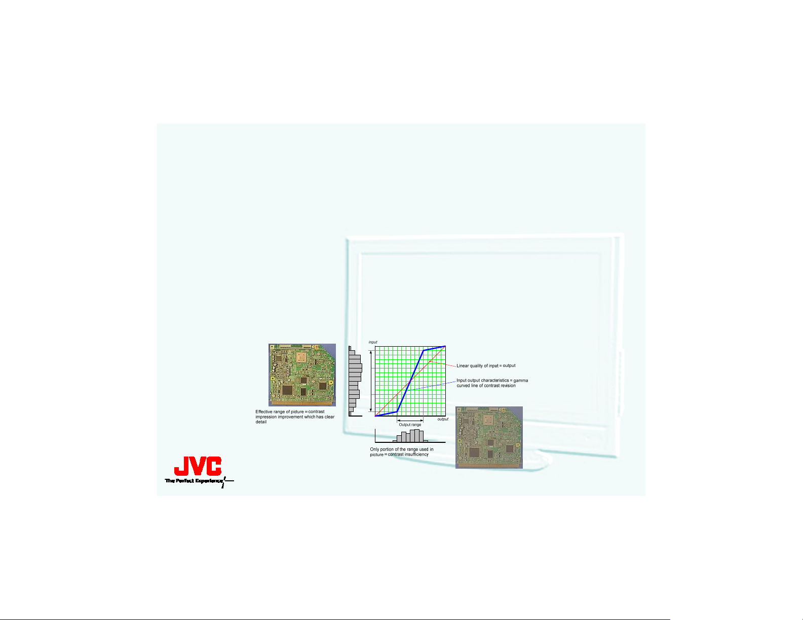
Iris Aperture Control (1)
Before use
Before use
Set brightness darkly
<ILA device’s dynamic range> : Use lower side only
<Picture's bit depth> : Becomes shallow
Slant of brightness is not smooth
s improved by ““
ItIt’’s improved by
“
Iris Aperture Control
“
Iris Aperture Control
”
”
Iris Aperture Control””
Iris Aperture Control
Page 9

Before the use of the Iris aperture control there was noticeable
Before the use of the Iris aperture control there was noticeable
brightness indications in the picture as shown in this slide. No
brightness indications in the picture as shown in this slide. No
the addition of the Iris aperture we can adjust the video status
the addition of the Iris aperture we can adjust the video status
improve the quality of the brightness.
improve the quality of the brightness.
Optical iris
Optical iris
•
Dark shading improvement
•
Dark shading improvement
•
Dark gray scale improvement
•
Dark gray scale improvement
w with
w with
to
to
Previously, if the Brightness Control was used to adjust the pic
Previously, if the Brightness Control was used to adjust the pic
which is how the Video Status Button on earlier models functione
which is how the Video Status Button on earlier models functione
would limit the
would limit the
shown in the right photo would be reduced and had the effect of
shown in the right photo would be reduced and had the effect of
showing defined STEPS in the brightness of a contoured object su
showing defined STEPS in the brightness of a contoured object su
as in this picture of a bottle
as in this picture of a bottle
not smooth).
not smooth).
Now with the addition of the Iris aperture we can adjust the vid
Now with the addition of the Iris aperture we can adjust the vid
status to improve the quality of the brightness.
status to improve the quality of the brightness.
ILA
’
ILA
overall dynamic range, the Picture Bit Depth as
’
ssoverall dynamic range, the Picture Bit Depth as
’
s rounded shape (
’
s rounded shape (
“
slant of brightness
“
slant of brightness
ture,
ture,
d, it
d, it
ch
ch
eo
eo
Page 10
Iris Aperture Control (2)
Iris Aperture
Iris Aperture
Choice
Choice
IMPORTANT:
"PICTURE ADJUST“ not
related Aperture.
“
VIDEO STATUS
“
VIDEO STATUS
”
Aperture controls Light value.
”
ÆÆAperture controls Light value.
(Three phases)
: MIDDLE
: OPEN
: CLOSE
: MIDDLE
“CLOSE” phase picture
SERVO MOTER
makes noise
Page 11

The iris aperture controls the light value or amount
The iris aperture controls the light value or amount
of light when pressing the video status button on
of light when pressing the video status button on
the remote control. When in the theater mode the
the remote control. When in the theater mode the
iris is closed and the least amount of light is
iris is closed and the least amount of light is
permitted. When in the dynamic mode the iris is
permitted. When in the dynamic mode the iris is
open and the most light is permitted. During the
open and the most light is permitted. During the
standard and game setting the iris is set to the
standard and game setting the iris is set to the
middle position. The iris aperture is opened and
middle position. The iris aperture is opened and
closed by a servo motor which can be heard when
closed by a servo motor which can be heard when
pressing the video status form one setting to
pressing the video status form one setting to
another. The picture adjust in the main menu does
another. The picture adjust in the main menu does
not control the iris aperture and are not related.
not control the iris aperture and are not related.
Page 12
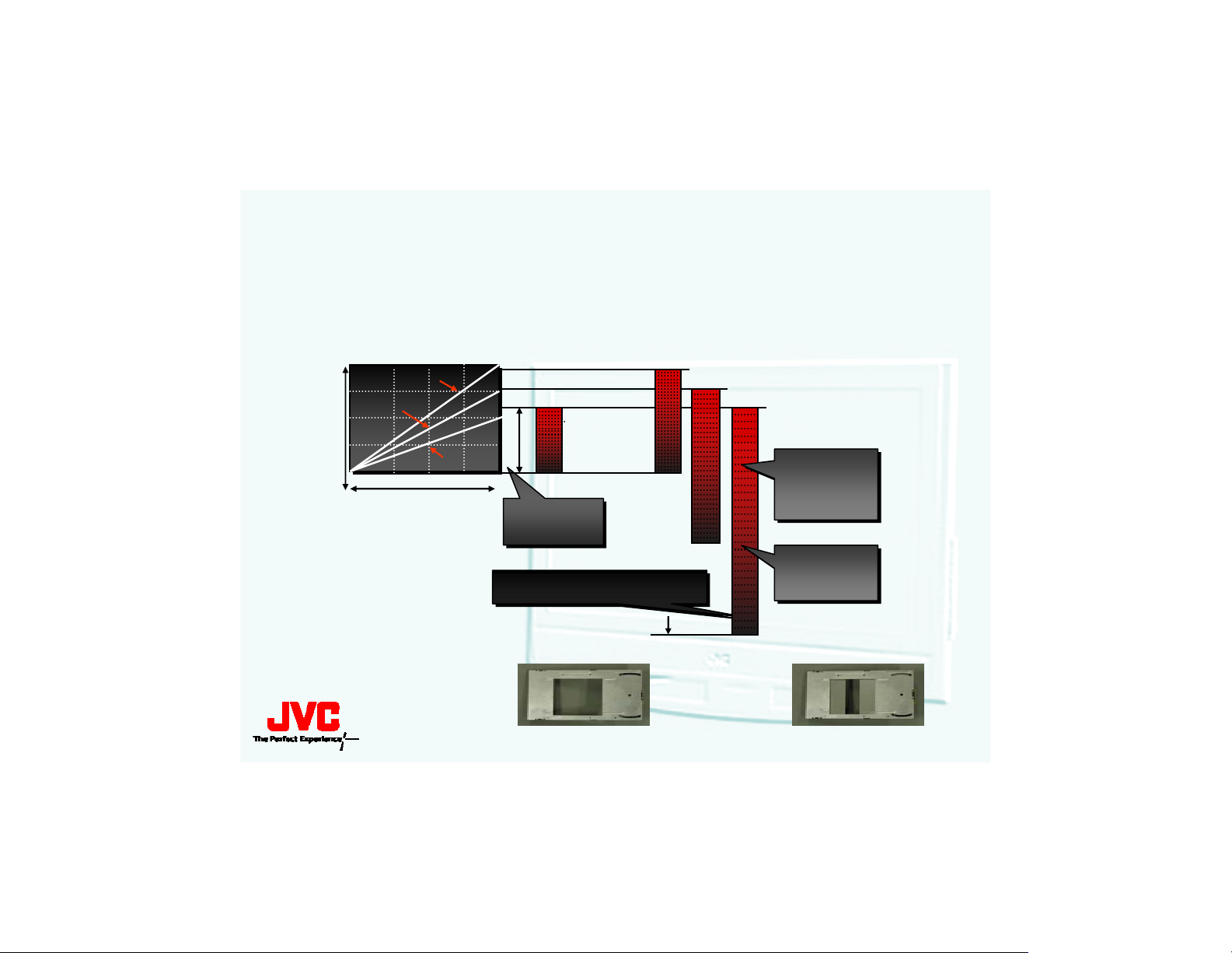
Optical Iris
Highest Accuracy Black Level Reproduction
Highest Accuracy Black Level Reproduction
Ideal for
Ideal for
Standard
Standard
Brightness Level
“
Theater Light Level
“
Theater Light Level
Dynamic
Dynamic
Theater
Theater
Input Level
Rough
Rough
Step
Step
Lower Black Level
Lower Black Level
Iris Open
(100%)
”
Viewing Environments
”
Viewing Environments
Dynamic
Standard
Theater
Iris Open
Iris 75%
Iris 50%
Contrast
Iris Closed
(50%)
Higher
Higher
Contrast
Ratio
Ratio
Smooth
Smooth
Step
Step
Page 13

In this slide you can view what the iris aperture
In this slide you can view what the iris aperture
would look like when it is in the closed and
would look like when it is in the closed and
open position. The graph shows the input level
open position. The graph shows the input level
verses the brightness level. As you can notice
verses the brightness level. As you can notice
that the contrast has a higher ratio and
that the contrast has a higher ratio and
smoother step as it changes to lower black
smoother step as it changes to lower black
levels when in the theater mode. The iris
levels when in the theater mode. The iris
aperture is 50% closed.
aperture is 50% closed.
Page 14
Iris Aperture Control (3)
Object Models
Object Models
Model Names
Model Names
56FH96
HDHD--56FH96
61FH96
HDHD--61FH96
70FH96
HDHD--70FH96
52G787, HD--
HDHD--52G787, HD
56G787, HD--
HDHD--56G787, HD
61G787, HD--
HDHD--61G787, HD
Circuit
Circuit
52G887
52G887
56G887
56G887
61G887
61G887
P.W.B ASS'Y
P.W.B ASS'Y
Name: IRIS P.W.B.
Name: IRIS P.W.B.
No. : SRA--
No. : SRA
Name: IRIS P.W.B.
Name: IRIS P.W.B.
No. : SRA--
No. : SRA
8301A--M2M2
8301A
83022
830
AA--M2
M2
Iris
Iris
OPTICAL/DRIVE ASSY
OPTICAL/DRIVE ASSY
Include
Include
Page 15

The FH96 models employ the iris PWB SRA--
The FH96 models employ the iris PWB SRA
8301A--
8301A
8302A--
8302A
interchangeable. These are the only models
interchangeable. These are the only models
that have iris aperture feature. Future models
that have iris aperture feature. Future models
will also employ this feature. The iris aperture
will also employ this feature. The iris aperture
is controlled by the main drive PWB and is
is controlled by the main drive PWB and is
mounted on top the main drive PWB.
mounted on top the main drive PWB.
M2 and the G787/G887 use the SRA--
M2 and the G787/G887 use the SRA
M2. these boards are not
M2. these boards are not
Page 16

1080P HD-ILA Projection Lens
Newly Developed for
Newly Developed for
1080P Displays
1080P Displays
Eleven Separate
Eleven Separate
Glass Components
Glass Components
One Aspheric
One Aspheric
Resin Coated Lens
Resin Coated Lens
Anti--
Anti
on Each Lens Element
on Each Lens Element
Reflective Coating
Reflective Coating
Page 17

Optical Lens improvement
Optical Lens improvement
•
The new projection lens developed to display in
Peripheral resolution performance
•
Peripheral resolution performance
•
Brightness improvement
•
Brightness improvement
•
Chromatic aberration improvement
•
Chromatic aberration improvement
The new projection lens developed to display in
1080P have eleven separate glass components.
1080P have eleven separate glass components.
Each lens element is coated with anti--
Each lens element is coated with anti
coating to reduce unwanted reflections (screen door
coating to reduce unwanted reflections (screen door
effect). We will discuss this effect in a future slide.
effect). We will discuss this effect in a future slide.
reflective
reflective
Page 18
1080P HD--
1080P HD
1080P Displays have
1080P Displays have
2 Million Pixels per chip
2 Million Pixels per chip
With 1080P displays, it is possible to
With 1080P displays, it is possible to
enjoy 1080i content at full 1080 x 1920
enjoy 1080i content at full 1080 x 1920
resolution.
resolution.
720P Displays have only
720P Displays have only
1 Million Pixels per chip
1 Million Pixels per chip
With 720P displays, it is necessary to
With 720P displays, it is necessary to
scale popular 1080i content to the
scale popular 1080i content to the
lower
lower
720 x 1280 resolution.
720 x 1280 resolution.
ILA
ILA
Page 19

This slide is presented to introduce you to the differences betw
This slide is presented to introduce you to the differences betw
used in previous models, and the new 1080P chip used, for exampl
used in previous models, and the new 1080P chip used, for exampl
models.
models.
Three Chip System
Three Chip System
Three Chips are
Three Chips are
better than one.
better than one.
Reflective Design
Reflective Design
Reflective is
Reflective is
better than
better than
transmissive..
transmissive
No Mechanical
No Mechanical
Color Wheel
Color Wheel
All Digital, Direct Drive
All Digital, Direct Drive
No Moving Parts in
No Moving Parts in
the Optical Engine Path
the Optical Engine Path
No
“
No
Simultaneous Display of Red, Green, & Blue
Fatigue
No Visible
93% Efficient
Rainbow
“
Rainbow
No Single--
No Single
Electro--
Electro
Micro Mirror
Micro Mirror
Simultaneous Display of Red, Green, & Blue
Color Channels for Film--
Color Channels for Film
Fatigue--
No Visible
“
Screen Door Effect
“
Screen Door Effect
93% Efficient
Highest Brightness
Highest Brightness
Excellent Contrast, with
Excellent Contrast, with
Linear Grayscale
Linear Grayscale
Realistic
Realistic
”
Effect
”
Effect
Chip,
Chip,
Mechanical
Mechanical
“
Rainbow
”
“
Rainbow
Free Extended Viewing
Free Extended Viewing
“
shadow detail
“
shadow detail
Artifacts
”
Artifacts
Like Images at All Times
Like Images at All Times
”
”
”
”
een the 720 resolution chip
een the 720 resolution chip
e, in the HD--
e, in the HD
56FH96
56FH96
Page 20
1080P HD-ILA
Horizontal Resolution 1920
Horizontal Resolution 1920
2,073,000 Pixels x 3 !!
2,073,000 Pixels x 3 !!
HD-ILA
1080p Chip
Vertical Resolution 1080
Vertical Resolution 1080
10.1 Mega pixels
per sq. in.
Vertical alignment of
Vertical alignment of
liquid crystal layer for
liquid crystal layer for
highest contrast
highest contrast
High aperture ratio
High aperture ratio
& high light efficiency
& high light efficiency
Page 21

The 1080P HD--
The 1080P HD
for red, blue and green devices, effectively producing
for red, blue and green devices, effectively producing
6,219,000 total pixels to produce the picture.
6,219,000 total pixels to produce the picture.
The measurement of each chip is:
The measurement of each chip is:
As described in previous classes, the LCD material in
As described in previous classes, the LCD material in
these chips is VERTICLLY aligned in a configuration much
these chips is VERTICLLY aligned in a configuration much
like individual threads and when viewed under a
like individual threads and when viewed under a
microscope, resemble that threaded description in that
microscope, resemble that threaded description in that
they are in a vertical, spiral shape.
they are in a vertical, spiral shape.
Arranging the LCD material in this fashion provides a high
Arranging the LCD material in this fashion provides a high
aperture ratio that has the effect of blocking a minimum
aperture ratio that has the effect of blocking a minimum
amount of the entering and reflected light and gives a
amount of the entering and reflected light and gives a
very high, 93% efficient use of available light from the high
very high, 93% efficient use of available light from the high
powered lamp in the Light Engine.
powered lamp in the Light Engine.
ILA chips have over 2 million pixels each
ILA chips have over 2 million pixels each
Page 22
Screen Door Effect
With LCD
With HD-ILA
Page 23

With
With
the light source is BEHIND the picture producing
the light source is BEHIND the picture producing
element. This is typical of LCD television and Thin
element. This is typical of LCD television and Thin
Film Transistor computer screens. The screen door
Film Transistor computer screens. The screen door
effect is a result of the shadowing of the pixel
effect is a result of the shadowing of the pixel
separations and of the driving devices (transistors)
separations and of the driving devices (transistors)
that are required to activate each pixel of an LCD
that are required to activate each pixel of an LCD
screen. The shadowing pixel walls, appearing as
screen. The shadowing pixel walls, appearing as
though you are looking through a screen door, and
though you are looking through a screen door, and
the driving transistors block light giving the
the driving transistors block light giving the
perception of reduced brightness.
perception of reduced brightness.
Transmissive
Transmissive
technology such as shown here,
technology such as shown here,
Page 24

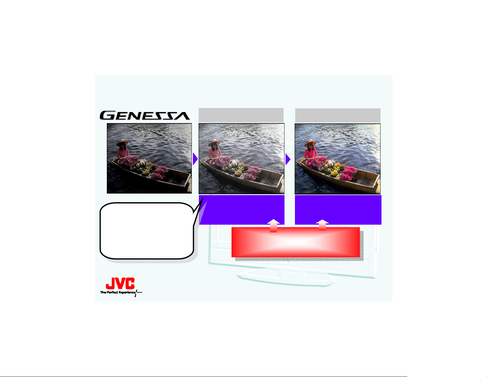
GENESSA
Gamma Correction
Gamma Correction
<Conventional : Static Gamma Correction >
<Conventional : Static Gamma Correction >
Gamma characteristics is fixed. Therefore, dark and bright area
Gamma characteristics is fixed. Therefore, dark and bright area
lost by contents of an picture.
lost by contents of an picture.
<New : Dynamic Gamma Correction >
<New : Dynamic Gamma Correction >
Gamma characteristics is variable. DGC preserves dark and bright
Gamma characteristics is variable. DGC preserves dark and bright
details.
details.
What “Gamma”?
Originally, Gamma means “Cam Inverse Gamma / CRT Gamma”.
Now, “Gamma Correction” means display devices
correction.
(or Control )
(or Control )
details are
details are
characteristic
area
area
Page 25

What is
What is
This term was originally used as a standard for producing the co
This term was originally used as a standard for producing the co
images received by a camera, the correct color temperature being
images received by a camera, the correct color temperature being
Originally, Gamma means
Originally, Gamma means
The camera is a picture producing device. The ILA can be consid
The camera is a picture producing device. The ILA can be consid
producing device. This can be compared to a musical instrument
producing device. This can be compared to a musical instrument
device, and an amplifier and speaker as the music re--
device, and an amplifier and speaker as the music re
In order for the two to match sound from production to reproduct
In order for the two to match sound from production to reproduct
must be kept. In video, the most critical standard is GAMMA.
must be kept. In video, the most critical standard is GAMMA.
In the ILA, the GAMMA is designed to be kept at 6500 degrees Kel
In the ILA, the GAMMA is designed to be kept at 6500 degrees Kel
temperature must be observed from full black (crushed) to satura
temperature must be observed from full black (crushed) to satura
black to full white is measured in IRE units (Institute of Radi
black to full white is measured in IRE units (Institute of Radio
the form of a non--
the form of a non
representation of value X for red and value Y for blue, with gre
representation of value X for red and value Y for blue, with gre
meeting point.
meeting point.
In older systems, Gamma Correction was a fixed setting and detai
In older systems, Gamma Correction was a fixed setting and detai
sacrificed for overall correct color temperature.
sacrificed for overall correct color temperature.
DGC or Dynamic Gamma Correction is an active constant monitoring
DGC or Dynamic Gamma Correction is an active constant monitoring
corrections are made automatically, depending on picture content
corrections are made automatically, depending on picture content
temperature is achieved. DGC samples areas of the picture from
temperature is achieved. DGC samples areas of the picture from
makes corrections to that particular section of the picture
makes corrections to that particular section of the picture
Now,
Now,
“
Gamma Correction (Gamma Control )
“
Gamma Correction (Gamma Control )
“
Cam Inverse Gamma / CRT Gamma
“
Cam Inverse Gamma / CRT Gamma
linear curve tracking from these two conditions and is a vector
linear curve tracking from these two conditions and is a vector
“
Gamma Correction
“
Gamma Correction
”
means display devices characteristic correction.
”
means display devices characteristic correction.
”
?
”
?
producing device.
producing device.
rrect color temperature with
rrect color temperature with
3500 degrees Kelvin.
3500 degrees Kelvin.
”
.
”
.
ered a picture re--
ered a picture re
being a music producing
being a music producing
ion, certain standards
ion, certain standards
vin. This color
vin. This color
tion (full white). This full
tion (full white). This full
o
Engineers standard). It takes
Engineers standard). It takes
en being the standard the
en being the standard the
ling of the picture was
ling of the picture was
so that a constant color
so that a constant color
black to full bright and
black to full bright and
–
actively and constantly.
–
actively and constantly.
of this vector and
of this vector and
Page 26
Dynamic Gamma Control
Dynamic Gamma Control
Dynamic Gamma Control
Examine distribution of brightness of each pixel.
1)1)Examine distribution of brightness of each pixel.
Concentrated band have heavy Information.
2)2)Concentrated band have heavy Information.
Emphasize detail of Concentrated band
3)3)Emphasize detail of Concentrated band
Even if there are plural concentrated bands, DGC functions.
4)4)Even if there are plural concentrated bands, DGC functions.
It is controlled for a picture change so that correction does not t
5)5)It is controlled for a picture change so that correction does no
become unnatural
become unnatural
Input range
Page 27

GENESSA correct a image every frame.
GENESSA correct a image every frame.
Correcting method
Correcting method
Dynamic Gamma Control
zzDynamic Gamma Control
Color Management
zzColor Management
CPU supports
CPU supports
correcting
correcting
and handles it
and handles it
fast.
fast.
Page 28

Color Management
Color Management
Color Management
Color Management works as follows.
Color Management works as follows.
Found
1)1)Found
Chroma and brightness levels gain, only
2)2)Chroma and brightness levels gain, only
lower a level of the whole the picture equally, in the range tha
3)3)lower a level of the whole the picture equally, in the range tha
can display.
can display.
4)
“
5 point color's are emphasized, and see the picture very well.
4)
“
5 point color's are emphasized, and see the picture very well.
“
5 point color
“
5 point color
Point 1 : green
Point 2 : yellow
Point 3 : red
Point 4 : blue
Point 5 : flesh tones
”
in the picture.
”
in the picture.
“
5 point color
“
5 point color
”
.
”
.
t a device
t a device
Page 29
Better Gradation & Color Reproduction
Adjusts gradation and
Adjusts gradation and
color reproduction for
color reproduction for
the best possible
the best possible
picture by constantly
picture by constantly
monitoring the picture
monitoring the picture
Intelligent Gamma
Clearer image of boat and face
Higher Contrast
Picture Processor (32bit CPU)
Picture Processor (32bit CPU)
Analyzes the picture data
Analyzes the picture data
Color Creation
Flowers and boat with vivid colors
Better Color Reproduction
Improved Performance for Optimum Picture Quality...
Page 30

•
Adds an extra axis to color management circuit for
•
Adds an extra axis to color management circuit for
improved color reproduction of skin tones
improved color reproduction of skin tones
•
Local sampling process targets specific color
•
Local sampling process targets specific color
regions
regions
Adding color management and dynamic effects
Adding color management and dynamic effects
together, the
together, the
enhancement of the details of dark areas with
enhancement of the details of dark areas with
Dynamic Gamma Correction (middle photo
Dynamic Gamma Correction (middle photo
the water and other items that would normally not
the water and other items that would normally not
be seen), and peaks otherwise washed out colors
be seen), and peaks otherwise washed out colors
(rightmost picture), both functions being a part of
(rightmost picture), both functions being a part of
the 32 bit Picture Processor CPU.
the 32 bit Picture Processor CPU.
Genessa
Genessa
system makes an
system makes an
–
look at
–
look at
Page 31

Lamp
Lamp Life:
Lamp Life:
Approximately*
Approximately*
7,500 Hours
7,500 Hours
User Replaceable
User Replaceable
Sealed Optical Engine
Sealed Optical Engine
No Dust Filter to Clean
No Dust Filter to Clean
Low Noise Cooling Fans
Low Noise Cooling Fans
for Quiet Operation
for Quiet Operation
1.5db Quieter Than Original HD--
--1.5db Quieter Than Original HD
ILA
ILA
* Can Vary Based on Actual Usage
* Can Vary Based on Actual Usage
Page 32

The new and improved lamps can be identified by the serial numbe
The new and improved lamps can be identified by the serial numbe
can seen if you look at the side opening towards the front of th
can seen if you look at the side opening towards the front of th
The new and improved lamps can be identified by the serial numbe
The new and improved lamps can be identified by the serial numbe
can seen if you look at the side opening towards the front of th
can seen if you look at the side opening towards the front of th
The 2004 model sets had an expected lamp life of 4000 hours. Th
The 2004 model sets had an expected lamp life of 4000 hours. Th
lamps that are in the G and FH model sets have an expected life
lamps that are in the G and FH model sets have an expected life
These new and improved lamps can be identified by the serial num
These new and improved lamps can be identified by the serial num
which can seen if you look at the side opening towards the front
which can seen if you look at the side opening towards the front
Please keep in mind that the life of any lamp is determined by t
Please keep in mind that the life of any lamp is determined by t
usage methods, and habits of the customer. The average HD TV us
usage methods, and habits of the customer. The average HD TV us
TV 4 to six hours a day, usually around prime--
TV 4 to six hours a day, usually around prime
The cooling system for the ILA unit in the Light Engine is a clo
The cooling system for the ILA unit in the Light Engine is a clo
meaning it draws in no outside air and therefore needs no dust f
meaning it draws in no outside air and therefore needs no dust f
Newer, lower noise cooling fans are used in our new models for q
Newer, lower noise cooling fans are used in our new models for q
operation of at least --
operation of at least
meter of the front of the set in a dead sound room.
meter of the front of the set in a dead sound room.
1.5db below the original 23db standard measured from 1
1.5db below the original 23db standard measured from 1
time.
time.
e lamp.
e lamp.
e lamp.
e lamp.
he installation,
he installation,
sed--
sed
ilter.
ilter.
r 5E23 which
r 5E23 which
r 5E23 which
r 5E23 which
e improved
e improved
of 7500 hours.
of 7500 hours.
ber 5E23
ber 5E23
of the lamp.
of the lamp.
er watches
er watches
loop system,
loop system,
uieter
uieter
Page 33

/
Page 34

History of D.I.S.T.
Generation
Generation
st
st
1
1
nd
nd
2
2
rd
rd
3
3
th
th
4
4
th
th
5
5
Year
Year
2001
2001
2002
2002
2003
2003
2004
2004
2005
2005
Put scaling chip
Put scaling chip
together and made
together and made
Designed color management chip
Designed color management chip
“
JCC5055
“
JCC5055
PAL signal support and g
PAL signal support and g
“
JCC5056
“
JCC5056
performance up. It is
performance up. It is
JCC5055 + JCC5057 +
JCC5055 + JCC5057 +
“
AMDP2
“
AMDP2
”
integrated
”
integrated
”
included
”
included
”
and new chip
”
and new chip
“
D.I.S.T.
“
D.I.S.T.
”
.
”
.
AMD2
AMD2
color/brightness control function, and
color/brightness control function, and
“
“
with
with
lobal
use.
lobal
use.
JCC5057 (Genessa)
JCC5057 (Genessa)
“
Y/C Sep.
“
Y/C Sep.
“
“
“
JCC5056
“
JCC5056
JCC5054.
JCC5054.
”
+
“
Video Decode
”
+
“
Video Decode
= JCC5060 (
= JCC5060 (
JCC5054 (for DSD)
JCC5054 (for DSD)
”
for flat device.
”
for flat device.
”
.
”
.
”
α
”
+ + α
JCC5068 )
JCC5068 )
”
”
Page 35

This slide indicates the five generations of D.I.S.T. IC
This slide indicates the five generations of D.I.S.T. IC
used in previous models up to today.
used in previous models up to today.
It merchandises enhancing the programmable image
It merchandises enhancing the programmable image
processing LSI AMDP2 and the new development which
processing LSI AMDP2 and the new development which
’
s
’
s
have been used for one for SD--
have been used for one for SD
processing LSI JCC5054 as "DET". Developing the
processing LSI JCC5054 as "DET". Developing the
integration revision LSI for flat panel JCC5056.
integration revision LSI for flat panel JCC5056.
Actualizing the color reappearance revision with DCC.
Actualizing the color reappearance revision with DCC.
The makers of AMDP2 and JCC5054 also develop the
The makers of AMDP2 and JCC5054 also develop the
JCC5055 which is used for the PAL signal correspond,
JCC5055 which is used for the PAL signal correspond,
entire world developments. The brightness・・
entire world developments. The brightness
the integration revision LSI for flat panel which JCC5057
the integration revision LSI for flat panel which JCC5057
z taking in is done (GENESSA) it develops as the
z taking in is done (GENESSA) it develops as the
succession device of JCC5056.
succession device of JCC5056.
ILA (DSD) combining
ILA (DSD) combining
color
color
tone are
tone are
Page 36

GENESSA Chip
GENESSA Chip <1st>
JCC5057
GENESSA Chip <2nd>
JCC5060
GENESSA Chip <2ndplus>
JCC5068
Page 37

5thD.I.S.T. w/ GENESSA
Page 38

This slide shows how HD Component video is processed
This slide shows how HD Component video is processed
in the JCC5060/JCC5068. The JCC5068 incorporates
in the JCC5060/JCC5068. The JCC5068 incorporates
all AD conversion in the A/D converter shown inside the
all AD conversion in the A/D converter shown inside the
black lines. The JCC5060 did not have this circuit, but
black lines. The JCC5060 did not have this circuit, but
instead, used a simpler A/D converter that is shown at
instead, used a simpler A/D converter that is shown at
the bottom left of the drawing and is marked with an
the bottom left of the drawing and is marked with an
asterisk (*). HD component video signal, JCC5060 A/D
asterisk (*). HD component video signal, JCC5060 A/D
converter
converter
It has been improved in the JCC5068 version of the chip.
It has been improved in the JCC5068 version of the chip.
It is only time to use for HD component video signal,
It is only time to use for HD component video signal,
JCC5060 A/D converter
JCC5060 A/D converter
It is improved with JCC5068.
It is improved with JCC5068.
’
s characteristic was not good.
’
s characteristic was not good.
’
s characteristic is not good.
’
s characteristic is not good.
Page 39

TH
5
Generation D.I.S.T.
High Performance Scaler
Current New
Reduced Jaggies
Intelligent Noise Reduction
Noise reduction
Noise detected
in image
is controlled,
automatically
New 3D Y/C with Component
Cross Color Elimination
Cross color &
dot interference
Reduced
cross color &
dot interference
Analysis area
Page 40

The improved performance of the DIST or SCALER is
The improved performance of the DIST or SCALER is
designed to reduce the
designed to reduce the
serrated lines on the edges of images and transitions of
serrated lines on the edges of images and transitions of
color.
color.
sampling of a solid color area where there is presently no
sampling of a solid color area where there is presently no
motion (MPEG noise) and uses that sample for
motion (MPEG noise) and uses that sample for
comparison and noise reduction in the entire picture. The
comparison and noise reduction in the entire picture. The
new version 3D Y/C filter is used to reduce or eliminate
new version 3D Y/C filter is used to reduce or eliminate
“
Cross Color
“
Cross Color
patterns like hound--
patterns like hound
presented.
presented.
The new DIST also uses an advance de--
The new DIST also uses an advance de
system that makes a 1080i signal smoother when passed
system that makes a 1080i signal smoother when passed
through the 1080p native conversion.
through the 1080p native conversion.
Intelegent
Intelegent
”
seen as
”
seen as
Noise Reduction is accomplished by a
Noise Reduction is accomplished by a
“
jaggies
“
jaggies
Chroma
Chroma
stooth
stooth
”
or what looks like
”
or what looks like
shimmering when complex
shimmering when complex
jackets or fine print shirts ate
jackets or fine print shirts ate
interlacing
interlacing
Page 41

HD Aspect Adjustment
HD PANORAMA:
HD PANORAMA:
Zooms in slightly, but does not distort the center of the image
Zooms in slightly, but does not distort the center of the image
Slightly stretches the outer edges to eliminate side bars and pr
Slightly stretches the outer edges to eliminate side bars and pr
images across the screen
images across the screen
CINEMA ZOOM:
CINEMA ZOOM:
Zooms HD 16:9 images, eliminating any remaining "letter box"
Zooms HD 16:9 images, eliminating any remaining "letter box"
Original HD Picture
Original HD Picture
Original HD Picture HD Cinema Zoom
Original HD Picture HD Cinema Zoom
HD Panorama
HD Panorama
ovide full
ovide full
Page 42

With respect to aspect ratios, this slide indicates the
With respect to aspect ratios, this slide indicates the
effect of altering a standard 4x3 aspect ratio by
effect of altering a standard 4x3 aspect ratio by
manipulating the Aspect Ratio button on the remote. As
manipulating the Aspect Ratio button on the remote. As
shown in this slide, there is obvious distortion of the
shown in this slide, there is obvious distortion of the
outer left and right areas of the picture using HD
outer left and right areas of the picture using HD
PANORAMA, but it does eliminate the Pillar Bars normally
PANORAMA, but it does eliminate the Pillar Bars normally
seen with 4x3 aspect ratio viewing. The use of CINEMA
seen with 4x3 aspect ratio viewing. The use of CINEMA
ZOOM eliminates most LETTERBOX presentations,
ZOOM eliminates most LETTERBOX presentations,
reducing or eliminating the dark margins created by the
reducing or eliminating the dark margins created by the
use of this type of display. If a true HD signal is being
use of this type of display. If a true HD signal is being
received (720p, 1080i), there are only three choices of
received (720p, 1080i), there are only three choices of
aspect ratio: FULL, HD PANORAMA, and CINEMA
aspect ratio: FULL, HD PANORAMA, and CINEMA
ZOOM. If an original 4x3 picture is displayed, NORMAL
ZOOM. If an original 4x3 picture is displayed, NORMAL
will be included in the choices for aspect ratio.
will be included in the choices for aspect ratio.
Page 43

ATSC
Page 44

DTT Standard
Digital Terrestrial Television Standard
Digital Terrestrial Television Standard
ATSC
ATSC
U.S.A. , Canada
Area
Area
U.S.A. , Canada
Korea, and other
Korea, and other
Modulation
Modulation
Video
Video
Compression
Compression
Audio
Audio
Compression
Compression
Advantage
Advantage
Disadvantage
Disadvantage
rganizerr
OOrganize
8VSB
8VSB
MPEG--22
MPEG
MPEG--
2 AC--33
MPEG
2 AC
Low
level electric field
Low
level electric field
Low cost (8VSB)
Low cost (8VSB)
Multi--
path
Multi
path
Mobile--
receive
Mobile
receive
ATSC
ATSC
Page 45

TERMS ON THIS SLIDE:
TERMS ON THIS SLIDE:
OFDM =
OFDM =
digital
digital
then transmitted simultaneously at different frequencies to the
then transmitted simultaneously at different frequencies to the
signal transmissions.
signal transmissions.
MPEG = Motion Pictures Entertainment Group. A method of compres
MPEG = Motion Pictures Entertainment Group. A method of compres
without a perceptible loss of information or causing
without a perceptible loss of information or causing
MPEG--
MPEG
8VSB =
8VSB =
digital television
digital television
ATSC, 8VSB carries 19.39Mb (
ATSC, 8VSB carries 19.39Mb (
significantly higher due to the addition of
significantly higher due to the addition of
the use of a
the use of a
intended to be used for ATSC
intended to be used for ATSC
standard instead.)
standard instead.)
SFN = Single Frequency Network.
SFN = Single Frequency Network.
DVB = Digital Video Broadcasting
DVB = Digital Video Broadcasting
ARIB = The
ARIB = The
organization
organization
designated frequency change support agency.
designated frequency change support agency.
ACAC--3 = Dolby Digital, or
for normal--
for normal
or
subwoofer
or
AAC =
AAC =
form, is a
form, is a
MPEG group
MPEG group
and
and
BC = UNKNOWN (Broadcast, maybe??
BC = UNKNOWN (Broadcast, maybe??
By a document, OFDM can be written as COFDM. This is the same th
By a document, OFDM can be written as COFDM. This is the same th
By a document, OFDM can be written as COFDM. This is the same th
By a document, OFDM can be written as COFDM. This is the same th
rthogonal FF
OOrthogonal
data
over a
data
over a
4 is 200 to 1 compression ratio.
4 is 200 to 1 compression ratio.
8VSB
8VSB
trellis encoder
trellis encoder
Association of Radio Industries and Businesses
Association of Radio Industries and Businesses
in
in
3 = Dolby Digital, or ACAC--33
range speakers (Right front, Center, Left Front, Right Rear and
range speakers (Right front, Center, Left Front, Right Rear and
subwoofer
Nokia..
Nokia
. The Dolby Digital format supports
. The Dolby Digital format supports
Advanced Audio Coding((
Advanced Audio Coding
digital audio
digital audio
by the end of April 1997. It was developed with contributions by y
by the end of April 1997. It was developed with contributions b
requency DD
requency
radio
wave. OFDM works by splitting the radio signal into multiple sm
radio
wave. OFDM works by splitting the radio signal into multiple sm
802.11a
802.11a
is the
is the
Japan
Japan
level
88--level
standard in the
standard in the
. There are also the similar modulations
. There are also the similar modulations
. ARIB is designated as the center of promotion of the efficient
. ARIB is designated as the center of promotion of the efficient
encoding and
encoding and
ivision MM
ivision
WLAN
WLAN
vestigial sideband modulation
vestigial sideband modulation
United States
United States
megabits
megabits
digital cable
digital cable
, is the common version containing up to 6 total channels of sou
, is the common version containing up to 6 total channels of sou
AAC
AAC
ultiplexing
ultiplexing
, 802.16 and
, 802.16 and
) of usable data per second, although the actual transmitted
) of usable data per second, although the actual transmitted
forward error correction
forward error correction
, but
, but
), also known as
), also known as
lossy
compression
lossy
compression
, an
, an
WiMAX
WiMAX
artifacting
artifacting
and
Canada
and
Canada
quadrature
quadrature
Mono
Mono
MPEG--
MPEG
FDM
modulation
FDM
modulation
receiver. OFDM reduces the amount of
receiver. OFDM reduces the amount of
technologies
technologies
in the picture. MPEG--
in the picture. MPEG
method adopted for terrestrial broadcast of the
method adopted for terrestrial broadcast of the
. (In the 6MHz (
. (In the 6MHz (
codes. The eight signal levels are selected with
codes. The eight signal levels are selected with
2VSB, ,
2VSB
amplitude modulation
amplitude modulation
, commonly known as
, commonly known as
and
Stereo
and
format
format
usages as well.
Stereo
usages as well.
2 Part 7
2 Part 7
. AAC was declared an international standard by
. AAC was declared an international standard by
technique for transmitting large amounts of
technique for transmitting large amounts of
use OFDM.
use OFDM.
sing a raw digital video and audio signal
sing a raw digital video and audio signal
megahertz
megahertz
4VSB
4VSB
Left Rear) and one channel for the
Left Rear) and one channel for the
, and also
, and also
Dolby, ,
Dolby
ing.
ing.
ing.
ing.
aller sub--
aller sub
2 is 50 to 1 compression,
2 is 50 to 1 compression,
) channel used for broadcast
) channel used for broadcast
, and
16VSB
, and
16VSB
(QAM) has become the industry
(QAM) has become the industry
ARIB
, is a
ARIB
, is a
use of the radio spectrum and
use of the radio spectrum and
MPEG--
4 Part 3
MPEG
4 Part 3
Fraunhofer((
Fraunhofer
signals that are
signals that are
crosstalk
crosstalk
ATSC
ATSC
bit rate
bit rate
. 16VSB was notably
. 16VSB was notably
standardization
standardization
nd, with 5 channels
nd, with 5 channels
in a slightly modified
in a slightly modified
FhG
),
AT&T, ,
FhG
),
AT&T
is
is
in
in
LFE, ,
LFE
the
the
Sony
Sony
Page 46

Program
Related ES (or PES) group.
Common System outline
Page 47

This is a slide showing the various processes
This is a slide showing the various processes
that are used to prepare the ATSC
that are used to prepare the ATSC
programming for transmission. This is
programming for transmission. This is
ENCODING of the signal. The receiver end
ENCODING of the signal. The receiver end
must do the DECODING.
must do the DECODING.
PSI =
PSI =
PMT = Program Map Table
PMT = Program Map Table
PAT = Program Association Table
PAT = Program Association Table
Program Specific Information
Program Specific Information
Page 48

DTT Map
Digital Terrestrial Television Map
Digital Terrestrial Television Map
<figure from DVB web site>
Page 49

There are seven basic different terrestrial
There are seven basic different terrestrial
television transmission systems. Their
television transmission systems. Their
distribution is shown on this map downloaded
distribution is shown on this map downloaded
from the Digital Video Broadcasting web site.
from the Digital Video Broadcasting web site.
The USA, Mexico, Canada, and Northern
The USA, Mexico, Canada, and Northern
Territories in green have either already adopted
Territories in green have either already adopted
or are considering and testing the ATSC
or are considering and testing the ATSC
system. All others are Digital Video Broadcast
system. All others are Digital Video Broadcast
except for Japan in red that uses Integrated
except for Japan in red that uses Integrated
Services Digital Broadcasting.
Services Digital Broadcasting.
Page 50

Modulation section
In ATSC, 8VSB Modulation system use.
In ATSC, 8VSB Modulation system use.
(8VSB : 8 level Vestigial Side Band)
(8VSB : 8 level Vestigial Side Band)
Page 51

ATI chip
JVC use
JVC use
DCR tuner
Without DCR tuner
ATI
designed ATSC chips.
ATI
designed ATSC chips.
DCR tuner
Without DCR tuner
use
use
NXT2003
NXT2003
use
use
™
and
and
Xilleon
Xilleon
™
THEATER
THEATER
™
™
™
™
310
310
226 . .
226
and
and
Xilleon
Xilleon
™
™
226 ..
226
Page 52

DCR = Digital Cable Ready
DCR = Digital Cable Ready
ATI = A manufacturer of Video Graphics Cards
ATI = A manufacturer of Video Graphics Cards
mostly used in computers.
mostly used in computers.
This slide shows the different ATI designed
This slide shows the different ATI designed
chips based on use of a Digital Cable Ready
chips based on use of a Digital Cable Ready
tuner or non--
tuner or non
use of one.
use of one.
Page 53

DTV Tuner Chip Maker
JVC
JVC
’
’
Main Chip maker
Main Chip maker
s DTV tuner units / main chip makers table
s DTV tuner units / main chip makers table
for ATSC
for ATSC
ATI
ATI
for DVB--TT
for DVB
ST
ST
for ISDB--TT
for ISDB
TOSHIBA
TOSHIBA
Page 54

ATSC = Advanced Television Systems
ATSC = Advanced Television Systems
Committee
Committee
ISDB--
ISDB
Broadcasting. The
Broadcasting. The
DVB--
DVB
Terrestrial
Terrestrial
T = Integrated Services Digital
T = Integrated Services Digital
T = Digital Video Broadcasting --
T = Digital Video Broadcasting
–
T is for Terrestrial
–
T is for Terrestrial
Page 55

Cooling System (1)
INTERNAL AIR FLOW [Removing DRIVE PWB]
The cooling block in optics
engine and the projection
space between projection
lens and screen are airtight
structure.
This is structure which
prevents dust go into the
optics engine.
Page 56

This slide deals with
This slide deals with
circulation system that is used to cool the ILA
circulation system that is used to cool the ILA
block in the optical section of the Light Engine.
block in the optical section of the Light Engine.
This closed system has no need for filtering
This closed system has no need for filtering
since there is no outside air taken into the unit
since there is no outside air taken into the unit
when chassis and cabinet are assembled.
when chassis and cabinet are assembled.
The temperature sensor is located inside the
The temperature sensor is located inside the
large exhaust port on the right of the chassis
large exhaust port on the right of the chassis
shown here.
shown here.
JVC
JVC
’
closed--
’
ssclosed
loop air
loop air
Page 57

Cooling System (2)
LAMP BLOCK AIR FLOW [Removing Lamp unit and Duct]
The air ventilates the lamp
unit after cooling the lamp
ballast and go out of the TV.
The sirocco cooling fan send
air to the lamp unit to
prompts cooling the lamp
block.
The lamp block is partitioned
with the internal airflow block
by the UV/IR filter and each
air flow does not intersect.
Page 58

The new type cooling system for Lamp and
The new type cooling system for Lamp and
Ballast are shown here. The lamp now has dual
Ballast are shown here. The lamp now has dual
cooling due to the configuration of the Sirocco
cooling due to the configuration of the Sirocco
(drum) fan located on top of the lamp cavity
(drum) fan located on top of the lamp cavity
that blows down on the bell of the lamp, and
that blows down on the bell of the lamp, and
the larger fan sandwiched between the ballast
the larger fan sandwiched between the ballast
assembly and lamp cavity. The Optical Block is
assembly and lamp cavity. The Optical Block is
isolated from these fans by virtue of the U/V
isolated from these fans by virtue of the U/V
filter glass at the light--
filter glass at the light
Engine.
Engine.
entry end of the Light
entry end of the Light
Page 59

Page 60

HD-56G786
Page 61

This is the wiring diagram associated with the
This is the wiring diagram associated with the
models HD--
models HD
It is similar to the diagram for the 2004 models
It is similar to the diagram for the 2004 models
of HD--
of HD
the ATSC tuner and fan, and the SD Card
the ATSC tuner and fan, and the SD Card
reader.
reader.
XXZ575 and 585 with the exception of
XXZ575 and 585 with the exception of
61Z786, 70G886, and HD56G786.
61Z786, 70G886, and HD56G786.
Page 62

Page 63

This is the block diagram and signal flow of the
This is the block diagram and signal flow of the
models we are discussing. (HD--
models we are discussing. (HD
70G886, and HD56G786). Please note the
70G886, and HD56G786). Please note the
signal flow of the added components, that is
signal flow of the added components, that is
the ATSC tuner and new rear panel inputs and
the ATSC tuner and new rear panel inputs and
outputs, 15 pin D--
outputs, 15 pin D
Sub computer, etc.
Sub computer, etc.
61Z786,
61Z786,
Page 64

Signal Flow
Page 65

This slide is to assist you with the NTSC and
This slide is to assist you with the NTSC and
ATSC signal flow.
ATSC signal flow.
Page 66

PWB For G886 and G786
Page 67

This is the Circuit Board list for the G886 and
This is the Circuit Board list for the G886 and
G786 models. It is important to note that all
G786 models. It is important to note that all
boards are the same EXCEPT for the Digital
boards are the same EXCEPT for the Digital
Signal Boards. They are unique to each
Signal Boards. They are unique to each
different model and should NOT be
different model and should NOT be
interchanged unless a sub is specifically
interchanged unless a sub is specifically
indicated through the parts system.
indicated through the parts system.
Page 68

HD-ILA
2
2
Video Path HD-XXGX86
Video Inputs
1
1. RF input
2. Input 1~4 (V and YC)
3. Digital (HDMI)
4. ATSC input
4
3
Page 69

In this diagram, using the numbers of the inputs
In this diagram, using the numbers of the inputs
that correspond to the numbers at the various
that correspond to the numbers at the various
location, the input paths and condition
location, the input paths and condition
descriptions are called out as you trace each
descriptions are called out as you trace each
one.
one.
Page 70

HD-ILA
Control Path HD-XXGX86
CN311
CN307
CN306
CN310
CN801
Fan
Contro
l
Fan
AC in
Therm
ostat
Lamp
Thermal
Interlock
Fan
Sens
SW
Remote
Side
PWB
CN00SW
Front LED
PWB
Terminal
PWB
ATSC
Tuner
Module
CN1502
CN9601
CN1302
CN9701
Fan
CN00FL
Remote in
CN10SW
Pwr ON
Receiver PWB
Tuner
CN10FL
CN100F
CN00F
Analog PWB
CN1001
SD Card
PWB
Function
CN00G
CN100R
CN10FC
CN001
CN90G
Power
PWB
CN100C
REGULATOR
Power Control
CN0FC
CN001
Digital
PWB
CN005
HDMI
1
DD comm.
HDMI
2
CN90BCN20B
CN305
CN90G
Power
PWB
CN90BL
DD
PWB
Fan
CN101
Ballast
CN102
1. Standby 5V from PS powers CPU
2. Power on from Remote or Front panel
3. CPU turns on the power. All circuits are powered up
4. CPU checks thermal sensor, interlock switch, fan, etc. If OK, then turns on the lamp
Page 71

This slide indicates the paths of the control
This slide indicates the paths of the control
signals that are used in the operation of the
signals that are used in the operation of the
ILA unit. The paths include those input from
ILA unit. The paths include those input from
the remote hand unit, the front panel operation
the remote hand unit, the front panel operation
of the power on command, functions of the
of the power on command, functions of the
side control panel, and the subsequent calls
side control panel, and the subsequent calls
from the microprocessor that manage
from the microprocessor that manage
switching, monitoring and control functions for
switching, monitoring and control functions for
fan control, interlock monitoring and thermal
fan control, interlock monitoring and thermal
sensor status.
sensor status.
Page 72

HD-ILA
Power Block Diagram
HD-XXGX86
Page 73

In this discussion of the POWER system, we will go over some ste
In this discussion of the POWER system, we will go over some ste
troubleshooting in an attempt to assist you in more efficient pr
troubleshooting in an attempt to assist you in more efficient pr
resolution. This chart was made with convenience of measurement
resolution. This chart was made with convenience of measurement
very good troubleshooting tool.
very good troubleshooting tool.
Starting at the top left of the diagram, the AC power from the w
Starting at the top left of the diagram, the AC power from the w
There is a temperature sensitive thermostat mounted on the lamp.
There is a temperature sensitive thermostat mounted on the lamp.
open, AC power cannot continue through the circuits. After the
open, AC power cannot continue through the circuits. After the
this switch, the next place to check (STEP 1) is at Diode D9111
this switch, the next place to check (STEP 1) is at Diode D9111
PWB. If there is AC present, move on to STEP 2 to check for the
PWB. If there is AC present, move on to STEP 2 to check for the
Standby 5 volts. The checkpoint for this voltage is at the POWE
Standby 5 volts. The checkpoint for this voltage is at the POWE
CN90G, PIN 1. This STB5V is used the Digital Module. It also go
CN90G, PIN 1. This STB5V is used the Digital Module. It also go
where it is regulated down to 3.3V by IC902. This is output on
where it is regulated down to 3.3V by IC902. This is output on
the digital module as the CPU power.
the digital module as the CPU power.
If the STB5V is present, move to STEP 3 and find the MAIN DRIVE
If the STB5V is present, move to STEP 3 and find the MAIN DRIVE
to see that the Lamp Cover Interlock Switch is closed. The meas
to see that the Lamp Cover Interlock Switch is closed. The meas
CN305 PIN 2. Proper closure of the switch is indicated by a 0 V
CN305 PIN 2. Proper closure of the switch is indicated by a 0 V
this point.
this point.
After this condition is verified as correct, move on to STEP 4 c
After this condition is verified as correct, move on to STEP 4 c
signal at CN90G, PIN 3. This HIGH from the Digital Module CPU c
signal at CN90G, PIN 3. This HIGH from the Digital Module CPU c
RY9201 and allows the AC voltage to progress through a resistor
RY9201 and allows the AC voltage to progress through a resistor
p by step
p by step
oblem discovery and
oblem discovery and
all outlet is applied.
all outlet is applied.
AC passes through
AC passes through
on the power supply
on the power supply
R SUPPLY PWB,
R SUPPLY PWB,
es to the analog board
es to the analog board
CN001 pins 28 & 29 to
CN001 pins 28 & 29 to
urement point is
urement point is
DC measurement at
DC measurement at
heck for a HIGH (5v)
heck for a HIGH (5v)
auses closure of
auses closure of
to D9201.
to D9201.
in mind. It is a
in mind. It is a
If this switch is
If this switch is
presence of the
presence of the
PWB. Here, check
PWB. Here, check
Page 74

Further checking, move to STEP 5 by measuring the voltage at CN9
Further checking, move to STEP 5 by measuring the voltage at CN9
NOTE
NOTE
GROUND, NOT CHASSIS GROUND.
GROUND, NOT CHASSIS GROUND.
voltage will read 160VDC. This will not be sufficient voltage t
voltage will read 160VDC. This will not be sufficient voltage t
and ignite the lamp, but will allow for the voltages measured fr
and ignite the lamp, but will allow for the voltages measured fr
that feed 13.5 volts to the REGULATOR PWB that will generate 5vd
that feed 13.5 volts to the REGULATOR PWB that will generate 5vd
12VDCto the Analog PWB and the DIGITAL MODULE. Presence of thes
12VDCto the Analog PWB and the DIGITAL MODULE. Presence of thes
be determined by measuring (STEP 6)
be determined by measuring (STEP 6)
CN003 PIN1
CN003 PIN1
function of the CPU on the Digital Module. This voltage is also
function of the CPU on the Digital Module. This voltage is also
voltage. This check for 32VDC at CN003 PIN 1 is just a more con
voltage. This check for 32VDC at CN003 PIN 1 is just a more con
check for this voltage.
check for this voltage.
CN003 PIN10
CN003 PIN10
CN003 PIN4
CN003 PIN4
CN003 PIN8
CN003 PIN8
The switched 12VDC can be measured at pin 2 of CN00D on the anal
The switched 12VDC can be measured at pin 2 of CN00D on the anal
If the above voltages are missing, move to STEP 7 and check for
If the above voltages are missing, move to STEP 7 and check for
PIN 4. This is the 13.5 volts that feeds the regulator board.
PIN 4. This is the 13.5 volts that feeds the regulator board.
The Audio Circuits are fed by a plus and minus 15VDC. These two
The Audio Circuits are fed by a plus and minus 15VDC. These two
checked as shown in STEP 8. The checkpoints are CN90AA PIN 1 An
checked as shown in STEP 8. The checkpoints are CN90AA PIN 1 An
Please notice the dotted line from the IC9501/T9501 block. The
Please notice the dotted line from the IC9501/T9501 block. The
this block is used to energize RY9201. RY9201 closes and applie
this block is used to energize RY9201. RY9201 closes and applie
L9201 and it
L9201 and it
the LAMP.
the LAMP.
! THIS IS A VOLTAGE THAT MUST BE CHECKED WITH REFERENCE TO HOT
! THIS IS A VOLTAGE THAT MUST BE CHECKED WITH REFERENCE TO HOT
With the POWER FACTOR CONTROL off, the
With the POWER FACTOR CONTROL off, the
o operate the lamp ballast
o operate the lamp ballast
om CHASSIS GROUND
om CHASSIS GROUND
32VDC This voltage is a loop through voltage used for PLL
32VDC This voltage is a loop through voltage used for PLL
used for TUNER
used for TUNER
venient place to
venient place to
13.5VDC checkpoint
13.5VDC checkpoint
9VDC checkpoint
9VDC checkpoint
5VDC checkpoint
5VDC checkpoint
13.5VDC at CN90B
13.5VDC at CN90B
voltages can be
voltages can be
18VDC generated by
18VDC generated by
s the full 380VDC via
s the full 380VDC via
’
s associated control circuits to operate the LAMP BALLAST and ig
’
s associated control circuits to operate the LAMP BALLAST and ig
0BL.
NOTE
0BL.
c, 9VDC and SW
NOTE
c, 9VDC and SW
e voltages can
e voltages can
og board.
og board.
d CN90AA PIN5.
d CN90AA PIN5.
NOTE
NOTE
nite
nite
Page 75

HD-ILA
Lamp and Fan Block
HD-XXGX86
Check Standby 5V
and Power on
command
Digital
board
Lamp Cover det
Check Lamp
Cover SW
Clossed (0V)
Fan x 3
Check Fan control signal and Fan OK signal. If fan
failure is detected, CN310(3) becomes 5V. Power shuts
Fan
Control
off.
3
Control (0~1V)
Fan Lock (0V)
STB5V
Main_POW
Tx
Rx
CN306
2
12V
5V
AC in
CN305
CN310
CN310
6
CN90G
1
2
3
13V -9V
Main Drive
3456
1
Power
4
17
CN308
Check AC input to
the power supply
Check Lamp
Supplies. 380V
CN90BL
3
1
CN311
5
413
380V
18V
Check all supplies
and 18V (Hot
ground)
to the Main Drive
board
7
2.5V
Lamp on(2.5V)
Lamp return
OK(0V), NG(5V)
Check Lamp ON signal. 2.5 V for 4 seconds and 0V for
6 seconds. In case, no lamp return (OK) within 3 tries
(30 seconds), warning appears and power goes off
CN101
Lamp
Ballast
1 3
Page 76

LAMP and FAN failures can be checked using this block diagram.
LAMP and FAN failures can be checked using this block diagram.
***POINT OUT EACH STEP AS YOU EXPLAIN IT****
***POINT OUT EACH STEP AS YOU EXPLAIN IT****
Step 1:
Step 1:
voltage there, check to see if the LAMP THERMOSTAT is OPEN.
voltage there, check to see if the LAMP THERMOSTAT is OPEN.
Step 2:
Step 2:
HIGH at CN90G PIN3 on the Power Supply board.
HIGH at CN90G PIN3 on the Power Supply board.
Step 3:
Step 3:
PIN 2 on the MAIN DRIVE BOARD. Proper closure of this switch i
PIN 2 on the MAIN DRIVE BOARD. Proper closure of this switch i
by a 0VDC reading.
by a 0VDC reading.
Step 4:
Step 4:
This line connects to the Power Supply board as CN90DD.
This line connects to the Power Supply board as CN90DD.
Step 5:
Step 5:
These voltages can be found at CN90BL on the POWER SUPPLY board.
These voltages can be found at CN90BL on the POWER SUPPLY board.
THESE 2 VOLTAGES ARE MEASURED WITH REFERENCE TO HOT GROUND,
THESE 2 VOLTAGES ARE MEASURED WITH REFERENCE TO HOT GROUND,
NOT CHASSIS GROUND.
NOT CHASSIS GROUND.
Step 6:
Step 6:
detected, the voltage at CN310 PIN 3 will be 5VDC.
detected, the voltage at CN310 PIN 3 will be 5VDC.
Check for the presence of AC voltage at CN90SE. If there is no
Check for the presence of AC voltage at CN90SE. If there is no
Check for Standby 5 volts at CN90G PIN 1 and an operational
Check for Standby 5 volts at CN90G PIN 1 and an operational
Check for LAMP COVER SWITCH INTERLOCK closure at CN306
Check for LAMP COVER SWITCH INTERLOCK closure at CN306
s indicated
s indicated
Measure for 13VDC at CN308 PIN 1 and --
Measure for 13VDC at CN308 PIN 1 and
Check the 2 supplies that provide voltage for LAMP operation.
Check the 2 supplies that provide voltage for LAMP operation.
At CN310 PIN 3 of the MAIN DRIVE BOARD, if a fan failure is
At CN310 PIN 3 of the MAIN DRIVE BOARD, if a fan failure is
9VDC at CN308 Pin 7.
9VDC at CN308 Pin 7.
Page 77

HD-ILA
Side
PWB
2
Rear
Jack
PWB
2
5
3
A4
Line
A1~A
3
Center Ch. In
D.Aud (Analog)
Audio Path HD-XXGX86
Receiver PWB
IC
1701
A.H.S. BBE ADC AMP LPF
IC
1252
SW
AUD/CPN SW
IC
1641
1140
Vari
Fix
MTS
Analog PWB
IC501
AVSW
IC301
IC
IC
1621
1661
IC501 IC301
A1 A2 A3 A4
Digital
PWB
D.Aud
(Digital)
HDMI
LC
IC
Filter
Tuner
HDMI(A) HDMI(D)
Center CH.
4
ATSC
Tuner
1
Audio Outputs
1. Speaker output
2. Line output
IC1140
Main
S.W
Line
Tuner
Audio Inputs
1. RF input
6
2. Input 1~4
3. HDMI (Analog)
4. HDMI (Digital)
5. Center CH
6. ATSC input
Page 78

Using the same methods as the previous signal
Using the same methods as the previous signal
path slide showed with the video paths, the
path slide showed with the video paths, the
audio signal can be traced with this diagram.
audio signal can be traced with this diagram.
The signals to be traced are indicated in the
The signals to be traced are indicated in the
lower right of this slide. The outputs are
lower right of this slide. The outputs are
named in the upper left of the slide.
named in the upper left of the slide.
Page 79

Self check mode
Before entering the Self check mode,
confirm that the setting of TV/CATV SW of
the REMOTE CONTROL UNIT is at the
"TV“ side and the setting of VCR/DVD SW
is at the "VCR" side.
Set to "0 minutes" using the [SLEEP
TIMER] key.
Press the [VIDEO STATUS] key and
[DISPLAY] key simultaneously, then enter the
service mode.
Press the [2] key (SELF CHECK) before the
service mode screen disappears.
Press the [SLEEP TIMER] key to enter Page
2 of the SELF CHECK MODE.
When the [RETURN+] key pressed, the first
page change screen.
Page 80

NOTE:
NOTE:
When a number key other than the
When a number key other than the
pressed in
pressed in
the SERVICE MENU SCREEN, the other
the SERVICE MENU SCREEN, the other
relevant
relevant
screen may be displayed.
screen may be displayed.
This is not used in the SELF CHECK. Press the
This is not used in the SELF CHECK. Press the
[MENU]
[MENU]
key to return to the SERVICE MENU SCREEN.
key to return to the SERVICE MENU SCREEN.
[2]
[2]
key is
key is
Page 81

LED Error Codes for HD-XXGX86
Page 82

DISPLAY METHOD WHEN RASTER IS NOT AVAILABLE
DISPLAY METHOD WHEN RASTER IS NOT AVAILABLE
In a state where a display screen does not appear due to the fai
In a state where a display screen does not appear due to the fai
of this unit, the POWER LED (blue) and LAMP LED (orange) can
of this unit, the POWER LED (blue) and LAMP LED (orange) can
light up and display a trouble mode.
light up and display a trouble mode.
The factors in case the power is forcibly shut down at the time
The factors in case the power is forcibly shut down at the time
failure are memorized and those are displayed.
failure are memorized and those are displayed.
EXPLANATION ON ACTION
EXPLANATION ON ACTION
If NG is detected on an item being diagnosed, turn off the power
If NG is detected on an item being diagnosed, turn off the power
this unit. As soon as the power goes off, turn on and off POWER
this unit. As soon as the power goes off, turn on and off POWER
LED and LAMP LED immediately. After the power is shut down, it
LED and LAMP LED immediately. After the power is shut down, it
becomes impossible to turn on the power until the power cable
becomes impossible to turn on the power until the power cable
is either plugged in or unplugged from the AC outlet.
is either plugged in or unplugged from the AC outlet.
•
When [1] and [3] take place at the same time, give priority to
•
When [1] and [3] take place at the same time, give priority to
and [2] will not take place simultaneously with [1] and [3].
and [2] will not take place simultaneously with [1] and [3].
lure
lure
of
of
[1],
[1],
on
on
Page 83

Adjustments for HD-XXGX86
After the replacement of the OPTICAL
BLOCK, projection lens focus adjustment and
drive convergence/projection adjustment are
required.
Page 84

Page 85

HD-56FH96
Page 86

FH96 has connectors labeled different form Z
FH96 has connectors labeled different form Z
and G series OP assembly has iris PWB
and G series OP assembly has iris PWB
Page 87

HD-56FH96
Page 88

Signal Flow For HD-XXFH96
Page 89

You can use this slide to follow the ATSC
You can use this slide to follow the ATSC
signal and the HDMI signal.
signal and the HDMI signal.
Page 90

PWB For FH96
Page 91

HD-ILA
Power Block Diagram
HD-XXFH96
Page 92

In this discussion of the POWER system, we will go over some ste
In this discussion of the POWER system, we will go over some ste
troubleshooting in an attempt to assist you in more efficient pr
troubleshooting in an attempt to assist you in more efficient pr
resolution. This chart was made with convenience of measurement
resolution. This chart was made with convenience of measurement
very good troubleshooting tool.
very good troubleshooting tool.
Starting at the top left of the diagram, the AC power from the w
Starting at the top left of the diagram, the AC power from the w
There is a temperature sensitive thermostat mounted on the lamp.
There is a temperature sensitive thermostat mounted on the lamp.
open, AC power cannot continue through the circuits. After the
open, AC power cannot continue through the circuits. After the
this switch, the next place to check (STEP 1) is at Diode D9111
this switch, the next place to check (STEP 1) is at Diode D9111
PWB. If there is AC present, move on to STEP 2 to check for the
PWB. If there is AC present, move on to STEP 2 to check for the
Standby 5 volts. The checkpoint for this voltage is at the POWE
Standby 5 volts. The checkpoint for this voltage is at the POWE
CNA2, PIN 1. This STB5V is used the Digital Module. It also goe
CNA2, PIN 1. This STB5V is used the Digital Module. It also goe
where it is regulated down to 3.3V by IC902. This is output on
where it is regulated down to 3.3V by IC902. This is output on
the digital module as the CPU power.
the digital module as the CPU power.
If the STB5V is present, move to STEP 3 and find the MAIN DRIVE
If the STB5V is present, move to STEP 3 and find the MAIN DRIVE
to see that the Lamp Cover Interlock Switch is closed. The meas
to see that the Lamp Cover Interlock Switch is closed. The meas
CNSW PIN 2. Proper closure of the switch is indicated by a 0 VD
CNSW PIN 2. Proper closure of the switch is indicated by a 0 VD
this point.
this point.
After this condition is verified as correct, move on to STEP 4 c
After this condition is verified as correct, move on to STEP 4 c
signal at CNA2, PIN 3. This HIGH from the Digital Module CPU ca
signal at CNA2, PIN 3. This HIGH from the Digital Module CPU ca
RY9201 and allows the AC voltage to progress through a resistor
RY9201 and allows the AC voltage to progress through a resistor
p by step
p by step
oblem discovery and
oblem discovery and
all outlet is applied.
all outlet is applied.
AC passes through
AC passes through
on the power supply
on the power supply
R SUPPLY PWB,
R SUPPLY PWB,
s to the analog board
s to the analog board
CN011 pins 23 & 24 to
CN011 pins 23 & 24 to
urement point is
urement point is
C measurement at
C measurement at
heck for a HIGH (5v)
heck for a HIGH (5v)
uses closure of
uses closure of
to D9201.
to D9201.
in mind. It is a
in mind. It is a
If this switch is
If this switch is
presence of the
presence of the
PWB. Here, check
PWB. Here, check
Page 93

Further checking, move to STEP 5 by measuring the voltage at CNB
Further checking, move to STEP 5 by measuring the voltage at CNB
NOTE
NOTE
GROUND, NOT CHASSIS GROUND.
GROUND, NOT CHASSIS GROUND.
voltage will read 160VDC. This will not be sufficient voltage t
voltage will read 160VDC. This will not be sufficient voltage t
and ignite the lamp, but will allow for the voltages measured fr
and ignite the lamp, but will allow for the voltages measured fr
that feed 13.5 volts to the POWER SUPPLY PWB that will generate
that feed 13.5 volts to the POWER SUPPLY PWB that will generate
SW 12VDCto the Analog PWB and the DIGITAL MODULE. Presence of t
SW 12VDCto the Analog PWB and the DIGITAL MODULE. Presence of t
can be determined by measuring (STEP 6)
can be determined by measuring (STEP 6)
CN003 PIN1
CN003 PIN1
function of the CPU on the Digital Module. This voltage is also
function of the CPU on the Digital Module. This voltage is also
voltage. This check for 32VDC at CN1DC PIN 15 is just a more co
voltage. This check for 32VDC at CN1DC PIN 15 is just a more co
check for this voltage.
check for this voltage.
CN1DC PIN6
CN1DC PIN6
CN1DC PIN12
CN1DC PIN12
CN1DC PIN8
CN1DC PIN8
The switched 12VDC can be measured at pin 2 of CNA3 on the analo
The switched 12VDC can be measured at pin 2 of CNA3 on the analo
If the above voltages are missing, move to STEP 7 and check for
If the above voltages are missing, move to STEP 7 and check for
PIN 4. This is the 13.5 volts that feeds the Power Supply board..
PIN 4. This is the 13.5 volts that feeds the Power Supply board
The Audio Circuits are fed by a plus and minus 15VDC. These two
The Audio Circuits are fed by a plus and minus 15VDC. These two
checked as shown in STEP 8. The checkpoints are CNA1 PIN 1 And
checked as shown in STEP 8. The checkpoints are CNA1 PIN 1 And
Please notice the dotted line from the IC9501/T9501 block. The
Please notice the dotted line from the IC9501/T9501 block. The
this block is used to energize RY9201. RY9201 closes and applie
this block is used to energize RY9201. RY9201 closes and applie
L9201 and it
L9201 and it
the LAMP.
the LAMP.
! THIS IS A VOLTAGE THAT MUST BE CHECKED WITH REFERENCE TO HOT
! THIS IS A VOLTAGE THAT MUST BE CHECKED WITH REFERENCE TO HOT
With the POWER FACTOR CONTROL off, the
With the POWER FACTOR CONTROL off, the
o operate the lamp ballast
o operate the lamp ballast
om CHASSIS GROUND
om CHASSIS GROUND
32VDC This voltage is a loop through voltage used for PLL
32VDC This voltage is a loop through voltage used for PLL
used for TUNER
used for TUNER
nvenient place to
nvenient place to
13.5VDC checkpoint
13.5VDC checkpoint
9VDC checkpoint
9VDC checkpoint
5VDC checkpoint
5VDC checkpoint
13.5VDC at CN90B
13.5VDC at CN90B
voltages can be
voltages can be
18VDC generated by
18VDC generated by
s the full 380VDC via
s the full 380VDC via
’
s associated control circuits to operate the LAMP BALLAST and ig
’
s associated control circuits to operate the LAMP BALLAST and ig
L.
NOTE
L.
NOTE
5vdc, 9VDC and
5vdc, 9VDC and
g board.
g board.
CN90AA PIN5.
CN90AA PIN5.
NOTE
NOTE
hese voltages
hese voltages
nite
nite
Page 94

HD-ILA
Video Path HD-XXFH96
2
5
4
2
1
Video Inputs
1. RF input
2. Input 1~4 (V and YC)
3. Digital (HDMI 1 & 2)
4. ATSC input
5. PC input
3
Page 95

In this diagram, using the numbers of the inputs
In this diagram, using the numbers of the inputs
that correspond to the numbers at the various
that correspond to the numbers at the various
location, the input paths and condition
location, the input paths and condition
descriptions are called out as you trace each
descriptions are called out as you trace each
one.
one.
Page 96

HD-ILA
Control Path HD-XXFHX96
CNT
CNSW
CNF3
CNF2
CNF1
AC in
Therm
ostat
Lamp
Thermal
Sens
Interlock
SW
FanFanFan
Remote
Side
PWB
CNS1
Front LED
PWB
Tuner
PWB
CN1502
ATSC
Tuner
Module
CN1302
CN9701
Fan
CN00FL
T1
Remote in
CNS1
CNF CNT1
Pwr ON
Function
CN1001
SD Card
PWB
CNRE
CN011
Analog PWB
CN100C
CN8CV1
Card
Viewer
PWB
CNV1
Power Control
CN011
CN005
Digital
PWB
HDMI
1
DD comm.
CNOLV1
CN001
HDMI
2
CNLV1
CN83IR
PWB
CNIRM
Motor
CNIR
Iris
Iris
CNA2
Power
PWB
CNBL
CN102
Ballast
CN101
CNBCT
DD
PWB
1. Standby 5V from PS powers CPU
2. Power on from Remote or Front panel
3. CPU turns on the power. All circuits are powered up
4. CPU checks thermal sensor, interlock switch, fan, etc. If OK, then turns on the lamp
Page 97

This slide indicates the paths of the control
This slide indicates the paths of the control
signals that are used in the operation of the
signals that are used in the operation of the
ILA unit. The paths include those input from
ILA unit. The paths include those input from
the remote hand unit, the front panel operation
the remote hand unit, the front panel operation
of the power on command, functions of the
of the power on command, functions of the
side control panel, and the subsequent calls
side control panel, and the subsequent calls
from the microprocessor that manage
from the microprocessor that manage
switching, monitoring and control functions for
switching, monitoring and control functions for
fan control, interlock monitoring and thermal
fan control, interlock monitoring and thermal
sensor status. The card viewer is only available
sensor status. The card viewer is only available
for the HD--
for the HD
70FH96.
70FH96.
Page 98

HD-ILA
Lamp and Fan Block
HD-XXFH96
Check Standby 5V
and Power on
command
Digital
Main_POW
board
Lamp Cover det
Check Lamp
Cover SW
Clossed (0V)
Lamp Fan
Ballast Fan
OP Block Fan
Check Fan control signal and Fan OK signal. If fan
failure is detected, CNF1-3 becomes 5V. Power shuts
off.
Vcc
Lock
Vcc
Lock
Vcc
Lock
CNSW
2
3
AC in
STB5V
Tx
Rx
CNLV1
CNF3
21
CNA2
CNF2
12 1
6
1
3
1
2
Power
4
13V -11V
17
CNDD
Main Drive
CNF1
2
Control (0~1V)
Fan Lock (0V)
Check AC input to
the power supply
Check Lamp
Supplies. 380V
CNBL
3
1
CNBCT
5
413
380V
15V
Check all supplies
and 15V (Hot
ground)
to the Main Drive
board
7
2.5V
Lamp on(2.5V)
Lamp return
OK(0V), NG(5V)
Check Lamp ON signal. 2.5 V for 4 seconds and 0V for
6 seconds. In case, no lamp return (OK) within 3 tries
(30 seconds), warning appears and power goes off
1 3
CN102
Lamp
Ballast
Page 99

LAMP and FAN failures can be checked using this block diagram.
LAMP and FAN failures can be checked using this block diagram.
***POINT OUT EACH STEP AS YOU EXPLAIN IT****
***POINT OUT EACH STEP AS YOU EXPLAIN IT****
Step 1:
Step 1:
voltage there, check to see if the LAMP THERMOSTAT is OPEN.
voltage there, check to see if the LAMP THERMOSTAT is OPEN.
Step 2:
Step 2:
HIGH at CNA2 PIN3 on the Power Supply board.
HIGH at CNA2 PIN3 on the Power Supply board.
Step 3:
Step 3:
PIN 2 on the MAIN DRIVE BOARD. Proper closure of this switch i
PIN 2 on the MAIN DRIVE BOARD. Proper closure of this switch i
by a 0VDC reading.
by a 0VDC reading.
Step 4:
Step 4:
This line connects to the Power Supply board as CNDD.
This line connects to the Power Supply board as CNDD.
Step 5:
Step 5:
These voltages can be found at CNBL on the POWER SUPPLY board.
These voltages can be found at CNBL on the POWER SUPPLY board.
VOLTAGES ARE MEASURED WITH REFERENCE TO HOT GROUND, NOT
VOLTAGES ARE MEASURED WITH REFERENCE TO HOT GROUND, NOT
CHASSIS GROUND.
CHASSIS GROUND.
Step 6:
Step 6:
detected, the voltage at CNF1--
detected, the voltage at CNF1
Check for the presence of AC voltage at CNSE. If there is no
Check for the presence of AC voltage at CNSE. If there is no
Check for Standby 5 volts at CNA2 PIN 1 and an operational
Check for Standby 5 volts at CNA2 PIN 1 and an operational
Check for LAMP COVER SWITCH INTERLOCK closure at CNSW
Check for LAMP COVER SWITCH INTERLOCK closure at CNSW
s indicated
s indicated
Measure for 13VDC at CNDD PIN 1 and --
Measure for 13VDC at CNDD PIN 1 and
Check the 2 supplies that provide voltage for LAMP operation.
Check the 2 supplies that provide voltage for LAMP operation.
At CNF1--
At CNF1
3 PIN 2 of the MAIN DRIVE BOARD, if a fan failure is
3 PIN 2 of the MAIN DRIVE BOARD, if a fan failure is
3 PIN 2 will be 5VDC.
3 PIN 2 will be 5VDC.
11VDC at CNDD Pin 7.
11VDC at CNDD Pin 7.
THESE 2
THESE 2
Page 100

HD-ILA
Audio Path HD-XXFH96
2
Side
PWB
Center Ch. In
5
A1~A
2
3
Line
Tuner
PWB
1
D.Aud (Analog)
3
A4
IC
601
A.H.S. Audio
Analog PWB
IC101
Audio
select
IC106
Buffer
IC
604
Amp.
IC
301
SW
IC
607
ADC
IC106
HDMI(A/B)
IC
605
Digital
Out
Analog PWB
D.Aud
(Digital)
Digital
PWB
HDMI
HDMI
1
4
LC
Filter
LPF
2
IC101
A1A2 A3
Tuner
D.Aud
(Digital)
A4
Audio Outputs
1. Speaker output
2. Line output
Line
IC301
Center CH.
ATSC
ATSC
Tuner
Audio Inputs
1. RF input
2. Input 1~4
3. HDMI (Analog)
4. HDMI (Digital)
5. Center CH
6
6. ATSC input
 Loading...