

Page 1
SERVICE MANUAL
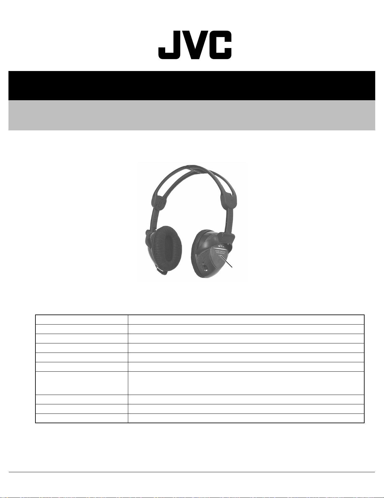
STEREO HEADPHONES
XC00920039
HA-NC100-J/C/E
Model No.
SPECIFICATION
Frequency response 10Hz - 22,000Hz
Noise cancellation frequency range 40Hz - 1,500Hz
Noise reduction more than 12 dB at 300Hz
Sensitivity 100dB/1mW (when ON), 103dB/1mW (when OFF)
Input impedance 36Ω (when ON), 64Ω (when OFF)
Power supply AAA battery (DC 1.5V) × 1
Battery life* approx. 25 hours** (using Manganese AAA battery),
approx. 50 hours** (using Alkaline AAA battery)
*Varies on operating conditions. **Without ambient noise.
Cord length 0 - 1.5m (4.9ft) (with L type stereo miniplug)
Mass 200g (7.06oz) (incl. cord and battery)
Accessories carrying pouch × 1 AAA battery (R03) × 1, dual plug adapter (for in-flight use) × 1
Design and specifications subject to change without notice.
COPYRIGHT © 2003 VICTOR COMPANY OF JAPAN, LIMITED
No.XC009
2003/10
Page 2
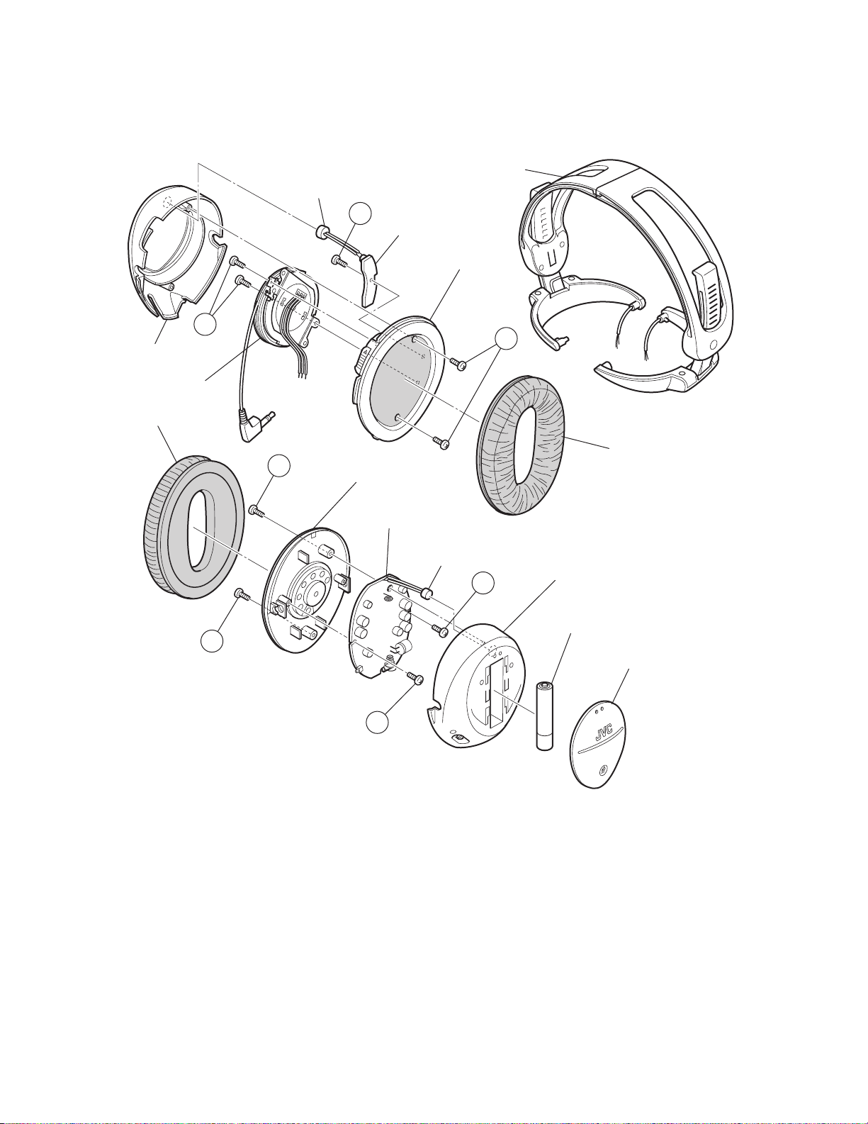
1.1 Disassembly method
SECTION 1
DISASSEMBLY
Headband ass'y
Microphone
E
Sub board
Driver unit ass'y (L)
C
Housing assembly (L)
Cord leader
Ear pad (R)
A
A
Driver unit ass'y (R)
B
Ear pad (L)
Main board
Microphone
Housing assembly (R)
D
Battery
Battery cover
D
(1) Remove the battery cover assembly and then take out a battery.
(2) Remove the ear pad (L) and (R) from the main assembly.
(3) Remove the four screws A and B attaching the housing assemblies, and take out the housing assembly (L) and (R) from the
main assembly.
(4) From the left side of the main assembly, remove the two screws C attaching the cord leader assembly, and take out the cord
leader assembly.
(5) From the right side of the main assembly, remove the two screws D attaching the main board, and take out the main board.
(6) From the left side of the main assembly, remove the screw E attaching the sub board, and take out the sub board.
Reference:
• Before attaching the housing assembly, inserted the microphone into a hollow of the housing assembly.
• P.C.Board assembly (Main board/Sub board, The part will not be supplied as an assembly.
1-2 (No.XC009)
Page 3

SECTION 2
ADJUSTMENT
2.1 Adjustment method
2.1.1 Measuring appliances required for adjustment
(1) Audio signal generator
(2) Audio amplifier
(3) Speaker
2.1.2 Required environment
Distance
30~40cm
2.1.3 Adjustment procedure
(1) Output 300Hz sine wave from the speaker.
(2) Remove the battery cover.
(3) Turn HA-NC100 on.
(4) Put on HA-NC100.
(5) Insert a driver in a hole for adjustment that is in the right
housing.
(6) Adjust HA-NC100 to minimize the 300Hz sound.
Amplifier
STANDBY
STANDBY/ON
PHONES
MASTER VOLUME
RX-DP20V
For LEFT CH
300Hz
Audio signal
Input
Right side housing
(The hole for adjustment)
generator
For RIGHT CH
(No.XC009)1-3
Page 4

3.1 Servicing guidelines
1. Measurement setup
(1) Audio signal generator
(output impedance : 600 )
(2) VTVM
(3) Oscilloscope
2. YES Nomal
No When the correct voltage
or waveform does not appear.
In put signal : 1.0 V RMS, 1kHz sine wave
SECTION 3
TROUBLESHOOTING
Symptom
No power
No sound
Defective
noise cancel
Check point Correct voltage / waveform Check pint and defective point
Between land BATT(+)
(1)
and BATT(-)
(2)
Between land L(+) and
L(-)
Between land R(+) and
L(-)
(3)
Same as the above
Approx. D.C 1.5V NO
Approx. 0.9Vp-p
Remove the microphone
from PCB, and input the
following input signals to
PCB directly.
(1)100Hz (2)1kHz
(3)2kHz
Approx.
YES
NO
YES
NO
YES
Check Battery terminal
in the R side housing.
Wires is cut.
Check S1 and D2,
peripheral circuits.
S1 detective
Damaged wire of cord
assembly, defective soldering
Check peripheral circuits
Check driver unit
Check peripheral circuits of
IC1(Lch), IC2(Rch)
Check a circuit between a
microphone input part and IC1,
and a circuit between a
microphone input part and IC2.
Check mic and wires
1-4 (No.XC009)
Page 5

(No.XC009)1-5
Page 6

VICTOR COMPANY OF JAPAN, LIMITED
AV & MULTIMEDIA COMPANY ACCESSORIES CATEGORY 1644, Shimotsuruma, Yamato, Kanagawa 242-8514, Japan
(No.XC009)
Printed in Japan
WPC
 Loading...