

Page 1
COMP ACT VHS CAMCORDER
CAMARA DE VIDEO VHS COMPACTO
CÂMERA VHS COMPACTA
GR-AX947UM
Compact VHS
ENGLISHPORTUGUÊS ESPAÑOL
INSTRUCTIONS
MANUAL DE INSTRUCCIONES
INSTRUÇÕES
LYT0107-001A
Page 2

2 EN
Dear Customer,
Thank you for purchasing the JVC Compact
VHS camcorder. Before use, please read the
safety information and precautions contained
in the following pages to ensure safe use of
your new camcorder.
Using This Instruction Manual
•All major sections and subsections are listed in
the Table Of Contents (Z pg. 7).
•Notes appear after most subsections. Be sure to
read these as well.
•Basic and advanced features/operation are
separated for easier reference.
It is recommended that you . . .
.... refer to the Index (Z pgs. 53 – 56) and
familiarize yourself with button locations, etc.
before use.
.... read thoroughly the Safety Precautions that
follow and cautions (Z pgs. 57, 58). They
contain extremely important information
regarding the safe use of your new camcorder.
SAFETY
PRECAUTIONS
WARNING:
TO PREVENT FIRE OR SHOCK
HAZARD, DO NOT EXPOSE
THIS UNIT TO RAIN OR
MOISTURE.
Warning on lithium battery
The battery used in this device may present a
fire or chemical burn hazard if mistreated. Do
not recharge, disassemble, heat above 100°C
or incinerate.
Replace battery with Maxell, Panasonic
(Matsushita Electric), Sanyo or Sony CR2025;
use of another battery may present a risk of fire
or explosion.
n Dispose of used battery promptly.
n Keep away from children.
n Do not disassemble and do not dispose of in
fire.
This camcorder is designed to be used with
NTSC-type colour television signals. It cannot
be used for playback with a television of a
different standard. However, live recording
and viewfinder playback are possible anywhere. Use the BN-V12U/V18U/V22U/V25U
battery packs and, to recharge them, the
provided multi-voltage AC Power Adapter/
Charger. (An appropriate conversion adapter
may be necessary to accommodate different
designs of AC outlets in different countries.)
NOTES:
●
The rating plate (serial number plate) and
safety caution are on the bottom and/or the
back of the main unit.
●
The rating plate (serial number plate) of the
AC Power Adapter/Charger is on its bottom.
This unit is produced to comply with Standard
IEC Publ. 65.
CAUTIONS:
n To prevent shock, do not open the cabinet.
No user serviceable parts inside. Refer
servicing to qualified personnel.
n When you are not using the AC Power
Adapter/Battery charger for a long period of
time, it is recommended that you disconnect
the power cord from AC outlet.
Page 3
EN 3
IMPORTANT PRODUCT
SAFETY INSTRUCTIONS
Electrical energy can perform many useful functions. But improper use can result in potential
electrical shock or fire hazards. This product has
been engineered and manufactured to assure your
personal safety. In order not to defeat the built-in
safeguards, observe the following basic rules for its
installation, use and servicing.
ATTENTION:
Follow and obey all warnings and instructions
marked on your product and its operating instructions. For your safety, please read all the safety and
operating instructions before you operate this
product and keep this manual for future reference.
INSTALLATION
1. Power Sources
Operate your product only from the type of power
source indicated on the marking label. If you are
not sure of the type of power supply to your home,
consult your product dealer or local power
company. If your product is intended to operate
from battery power, or other sources, refer to the
operating instructions.
2. Overloading
Do not overload wall outlets, extension cords, or
integral convenience receptacles as this can result
in a risk of fire or electric shock.
3. Power Cord Protection
Power supply cords should be routed so that they
are not likely to be walked on or pinched by items
placed upon or against them, paying particular
attention to cords at plugs, convenience receptacles, and the point where they exit from the
product.
4. Ventilation
Slots and openings in the cabinet are provided for
ventilation. To ensure reliable operation of the
product and to protect it from overheating, these
openings must not be blocked or covered.
•Do not block the openings by placing the product
on a bed, sofa, rug or other similar surface.
•Do not place the product in a built-in installation
such as a bookcase or rack unless proper
ventilation is provided or the manufacturer’s
instructions have been adhered to.
5. Wall or Ceiling Mounting
The product should be mounted to a wall or ceiling
only as recommended by the manufacturer.
ANTENNA INSTALLATION
INSTRUCTIONS
1. Outdoor Antenna Grounding
If an outside antenna or cable system is connected
to the product, be sure the antenna or cable system
is grounded so as to provide some protection
against voltage surges and built-up static charges.
Article 810 of the National Electrical Code, ANSI/
NFPA 70, provides information with regard to
proper grounding of the mast and supporting
structure, grounding of the lead-in wire to an
antenna discharge unit, size of grounding conductors, location of antenna discharge unit, connection
to grounding electrodes, and requirements for the
grounding electrode.
2. Lightning
For added protection for this product during a
lightning storm, or when it is left unattended and
unused for long periods of time, unplug it from the
wall outlet and disconnect the antenna or cable
system. This will prevent damage to the product
due to lightning and power-line surges.
3. Power Lines
An outside antenna system should not be located in
the vicinity of overhead power lines or other
electric light or power circuits, or where it can fall
into such power lines or circuits. When installing an
outside antenna system, extreme care should be
taken to keep from touching such power lines or
circuits as contact with them might be fatal.
EXAMPLE OF ANTENNA GROUNDING AS PER
NATIONAL ELECTRICAL CODE, ANSI/NFPA 70
ANTENNA
LEAD IN WIRE
GROUND CLAMP
ANTENNA
DISCHARGE UNIT
(NEC SECTION
ELECTRIC SERVICE
EQUIPMENT
POWER SERVICE GROUNDING ELECTRODE SYSTEM
(NEC ART 250. PART H)
NEC – NATIONAL ELECTRICAL CODE
810-20)
GROUNDING CONDUCTORS
(NEC SECTION 810-21)
GROUND CLAMPS
Page 4
4 EN
USE
1. Accessories
To avoid personal injury:
•Do not place this product on an unstable cart,
stand, tripod, bracket or table. It may fall, causing
serious injury to a child or adult, and serious
damage to the product.
•Use only with a cart, stand, tripod, bracket, or
table recommended by the manufacturer or sold
with the product.
•Use a mounting accessory recommended by the
manufacturer and follow the manufacturer’s
instructions for any mounting of the product.
•Do not try to roll a cart with small casters across
thresholds or deep-pile carpets.
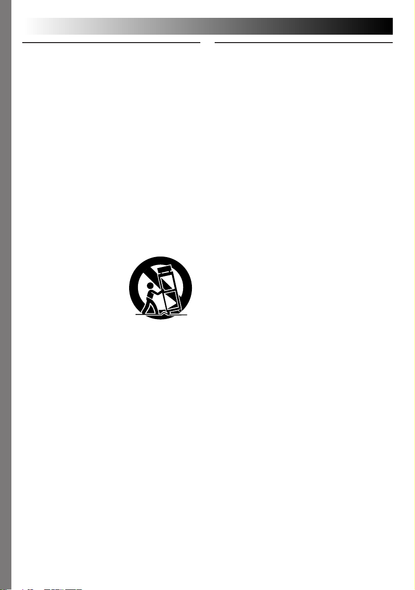
2. Product and Cart Combination
A product and cart combination should be moved
with care. Quick stops, excessive force, and uneven
surfaces may cause the product and cart combination to overturn.
3. Water and Moisture
Do not use this product
near water—for example,
near a bath tub, wash
bowl, kitchen sink or
laundry tub, in a wet
basement, or near a
swimming pool and the
like.
4. Object and Liquid Entry
Never push objects of any kind into this product
through openings as they may touch dangerous
voltage points or short-out parts that could result in
a fire or electric shock. Never spill liquid of any
kind on the product.
5. Attachments
Do not use attachments not recommended by the
manufacturer of this product as they may cause
hazards.
6. Cleaning
Unplug this product from the wall outlet before
cleaning. Do not use liquid cleaners or aerosol
cleaners. Use a damp cloth for cleaning.
7. Heat
The product should be situated away from heat
sources such as radiators, heat registers, stoves, or
other products (including amplifiers) that produce
heat.
PORTABLE CART WARNING
(Symbol provided by RETAC)
SERVICING
1. Servicing
If your product is not operating correctly or exhibits
a marked change in performance and you are
unable to restore normal operation by following the
detailed procedure in its operating instructions, do
not attempt to service it yourself as opening or
removing covers may expose you to dangerous
voltage or other hazards. Refer all servicing to
qualified service personnel.
2. Damage Requiring Service
Unplug this product from the wall outlet and refer
servicing to qualified service personnel under the
following conditions:
a. When the power supply cord or plug is damaged.
b. If liquid has been spilled, or objects have fallen
into the product.
c. If the product has been exposed to rain or water.
d. If the product does not operate normally by
following the operating instructions. Adjust only
those controls that are covered by the operating
instructions as an improper adjustment of other
controls may result in damage and will often
require extensive work by a qualified technician
to restore the product to its normal operation.
e. If the product has been dropped or damaged in
any way.
f. When the product exhibits a distinct change in
performance—this indicates a need for service.
3. Replacement Parts
When replacement parts are required, be sure the
service technician has used replacement parts
specified by the manufacturer or have the same
characteristics as the original part. Unauthorized
substitutions may result in fire, electric shock or
other hazards.
4. Safety Check
Upon completion of any service or repairs to this
product, ask the service technician to perform safety
checks to determine that the product is in safe
operating condition.
Page 5
QUICK OPERATION GUIDE
2
1
3
3
1
2
EN 5
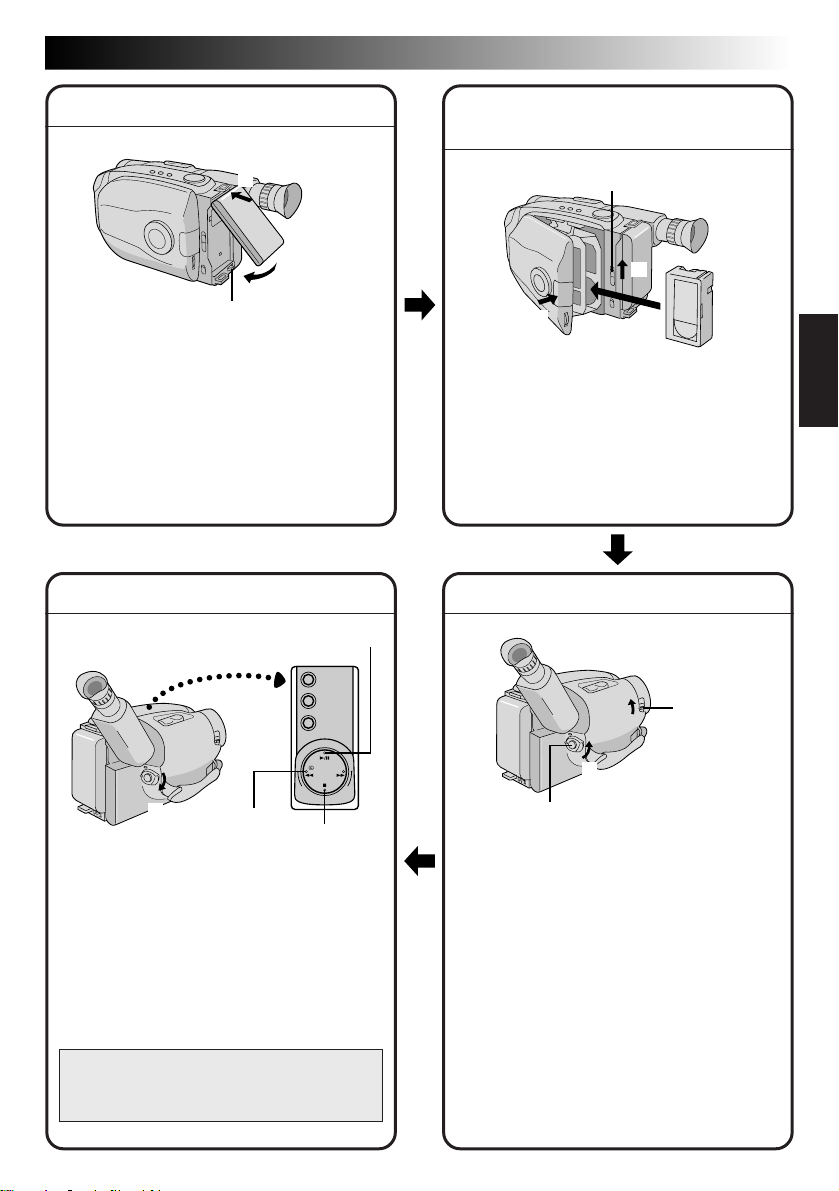
SUPPLY POWER
Hook on.
1
Push in.
2
BATT. RELEASE
Using the battery pack
Hook-on the battery pack’s top end to the
1
camcorder. (Charging procedure, Z pg. 8)
2 Push in the battery pack until it locks into
place.
To remove the battery pack
Slide BATT. RELEASE and pull out the battery
pack.
PLAYBACK
PLAY/PAUSE
INSERTING A VIDEO
CASSETTE
EJECT
PUSH
1 Slide EJECT to open the cassette holder.
2 Insert a video cassette.
3 Press PUSH to close the cassette holder.
(For more details, Z pg. 13)
SHOOTING
3
1
Set to “PLAY”
2
REW
1 Set the Power Switch to “PLAY”.
2 Press REW.
— The tape will automatically stop at the
beginning of the tape.
3 Press PLAY/PAUSE.
— Playback starts and the playback picture
appears.
•To stop playback, press STOP.
(For more details,
Or simply play back the tape on a VHS
VCR using the Cassette Adapter (VHS
Playpak). Z pg. 36
Z pg. 38.)
STOP
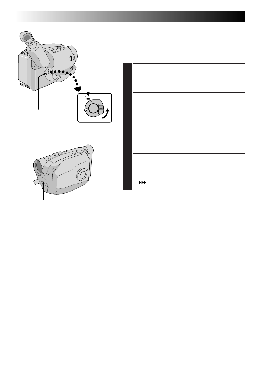
LENS COVER
Open/Close
Switch
Set to “CAMERA”
Recording Start/Stop Button
1 Slide the LENS COVER Open/Close Switch
to open the lens cover.
2 Set the Power Switch to “CAMERA”.
— The power indicator will light and an
image will appear.
3 Press the Recording Start/Stop Button.
— Recording starts.
•To stop recording temporarily, momentarily
press the Recording Start/Stop Button once
again.
(For more details,
Z pgs. 16, 17)
Page 6
6 EN
MAJOR FEATURES
REMEMBER
The Logical Choice
The only compact video
cassettes that can be
used with your VHS VCR*
Program AE with Special
Effects (
n Auto Mode Lock
n Auto Mode Release
n Electronic Fog Filter
n ND Effect n Sepia n Twilight
n Sports n Nega/Posi
n 1/2000 sec. High Speed Shutter
Z pg. 22)
Integrated Auto Light
Z pg. 21)
(
Picture Stabilizer (Z pg. 19)
Digital Hyper Zoom
Z pg. 18)
(
Zoom-in
Zoom-out
Program Manager
II
(Z pg. 22 – 35)
Program AE with Special Effects,
Fade/Wipe, Wide, Super LoLux,
Instant Title, Menu Adjustment
(Focus, Exposure Control and so on.)
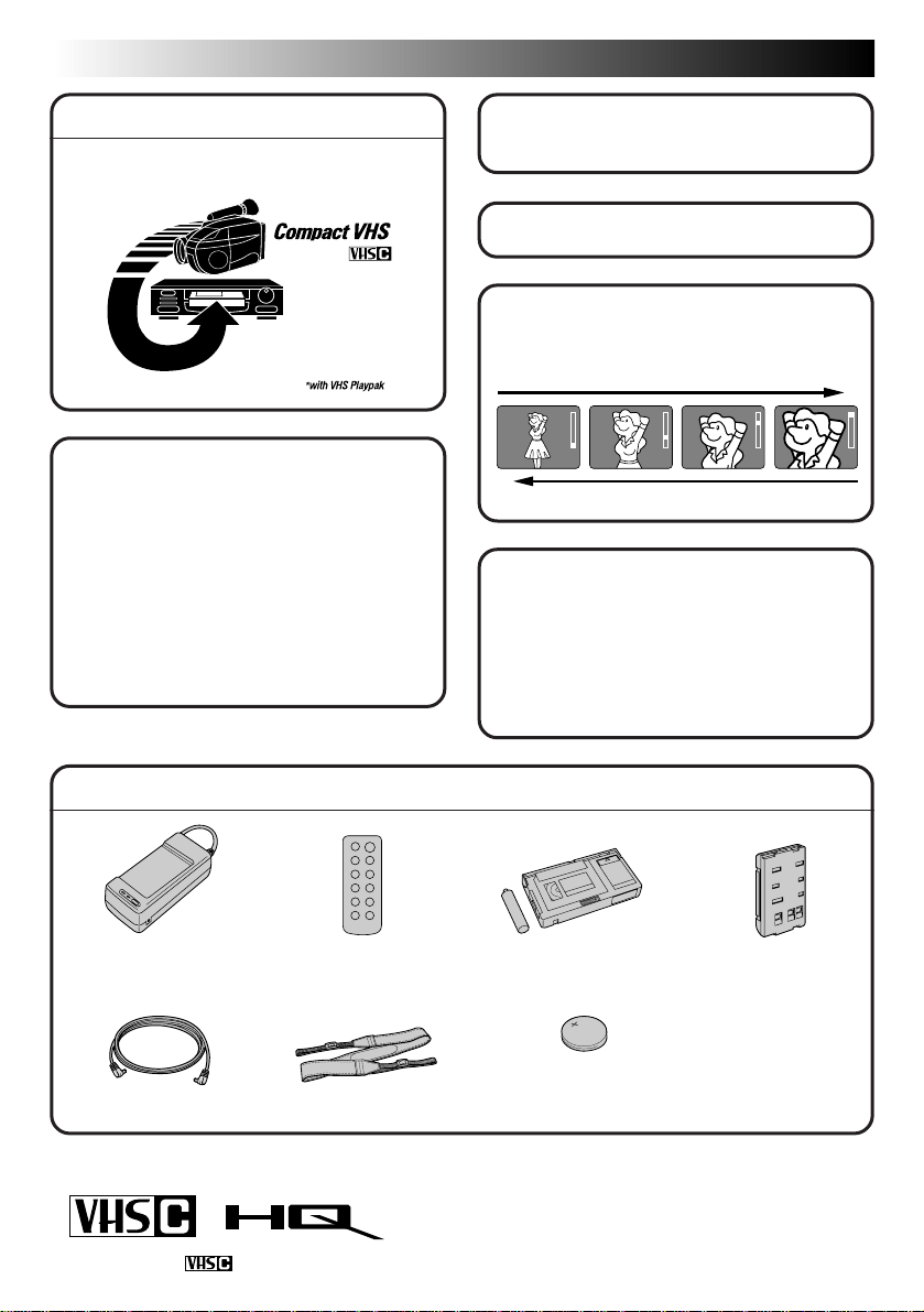
PROVIDED ACCESSORIES
•AC Power Adapter/
Charger AA-V15U
•DC Cord
Cassettes marked can be used with this camcorder.
•Remote Control
Unit RM-V705U
• Shoulder Strap
• Cassette Adapter
(VHS Playpak) C-P7U
•Lithium Battery CR2025
(clock operation and
remote control unit)
•Battery Pack
BN-V18U
Page 7

CONTENTS
GETTING STARTED
Power .............................................................................................. 8
Clock (Lithium) Battery Insertion/Removal................................................. 10
Date/Time Setting ............................................................................. 11
Recording Mode Setting ....................................................................... 12
Tape Length Setting ............................................................................12
Loading/Unloading A Cassette ............................................................... 13
Grip Adjustment ................................................................................ 14
Viewfinder Adjustment ........................................................................14
Shoulder Strap Attachment.................................................................... 15
Tripod Mounting ................................................................................ 15
EN 7
8
RECORDING
Basic Recording .................................................................................16
Basic Features .................................................................................. 18
Advanced Features ............................................................................. 22
PLAYBACK
Using The Cassette Adapter................................................................... 36
Basic Connections............................................................................... 37
Basic Playback .................................................................................. 38
Features ......................................................................................... 39
TAPE DUBBING
USING REMOTE CONTROL UNIT
Random Assemble Editing .....................................................................44
Insert Editing ....................................................................................48
Audio Dubbing ..................................................................................49
USER MAINTENANCE
TROUBLESHOOTING
INDEX
Viewfinder Indications .........................................................................53
Controls ..........................................................................................54
Connectors....................................................................................... 54
Indicators ........................................................................................54
Other Parts...................................................................................... 54
Terms ............................................................................................. 56
16
36
41
42
50
51
53
CAUTIONS
SPECIFICATIONS
OPTIONAL ACCESSORIES
57
59
59
Page 8
8 EN
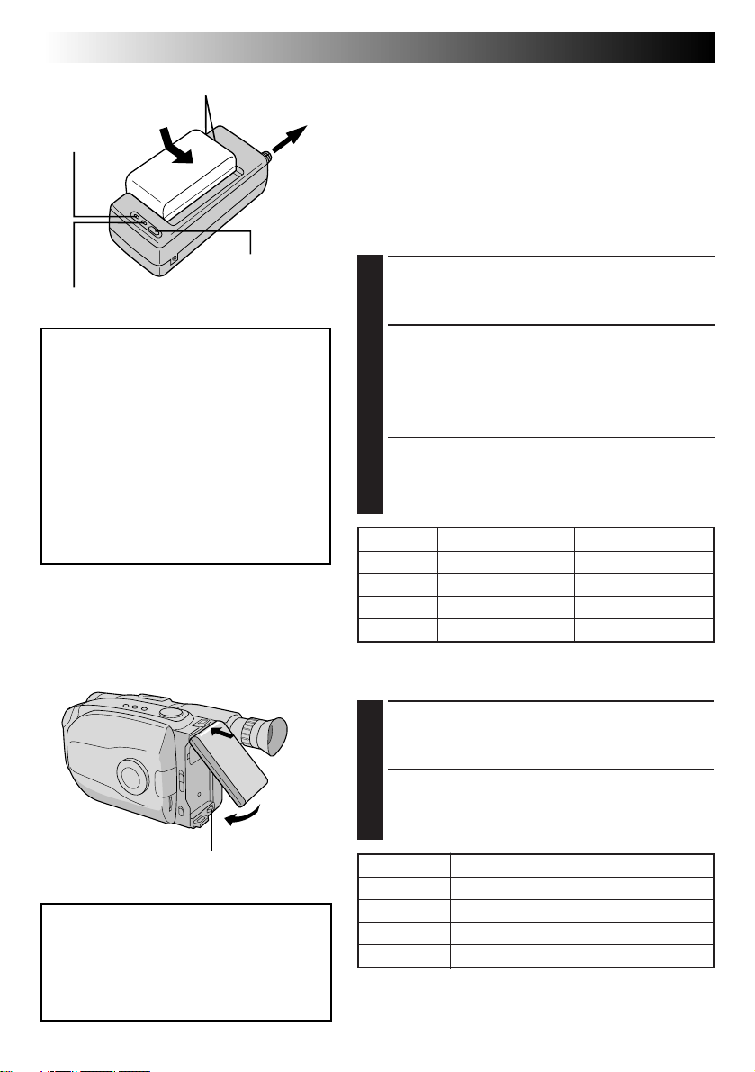
CHG. (charge)
indicator
REFRESH indicator
Marks
To AC outlet
REFRESH switch
GETTING STARTED
Power
This camcorder’s 3-way power supply system lets you
choose the most appropriate source of power.
NOTES:
●
No function is available without power supply.
●
Use only specified power supply.
●
Do not use provided power supply units with other
equipment.
CHARGING THE BATTERY PACK
SUPPLY POWER
Connect the charger’s AC power cord to a wall
1
outlet.
REFRESH
The AC power adapter features a REFRESH
function that allows you to fully discharge
the battery pack before recharging. Perform
the REFRESH function after no less than 5
chargings.
To discharge the battery . . .
..... attach the battery pack to the adapter
as shown in the above illustration.
Then push REFRESH. The REFRESH
indicator lights when discharging
starts, and goes out when discharging
is complete.
Hook on.
1
1
Push in.
2
BATT. RELEASE
ATTENTION:
Before detaching the power source,
make sure that the camcorder’s power
is turned off. Failure to do so can result
in a camcorder malfunction.
ATTACH BATTERY PACK
Align the marks and slide the battery pack in the
2
direction of the arrow until it locks in place.
•The CHG. indicator begins blinking to indicate
charging has started.
DETACH BATTERY PACK
When the CHG. indicator stops blinking but stays lit,
3
charging is finished. Slide the battery pack opposite
the direction of the arrow.
BATT. PACK CHARGE DISCHARGE
BN-V12U approx. 1 hr. 10 min. approx. 3 hrs. 30 min.
BN-V18U approx. 1 hr. 40 min. approx. 5 hrs. 30 min.
BN-V22U approx. 2 hrs. 10 min. approx. 7 hrs.
BN-V25U approx. 2 hrs. 40 min. approx. 10 hrs.
USING THE BATTERY PACK
ATTACH BATTERY PACK
Hook its top end to the camcorder and push the
1
battery pack in until it locks in place.
DETACH BATTERY PACK
Slide BATT. RELEASE and pull out the battery pack.
2
BATT. PACK Approximate recording time (unit: min.)
BN-V12U 75 ( 40 )
BN-V18U 110 ( 65 )
BN-V22U 150 ( 90 )
BN-V25U 200 ( 120 )
( ) : when the video light is on.
Page 9
EN 9
CHARGE MARKER
Charge marker
A charge marker is provided on the battery pack to
help you remember whether it has been charged or
not. Two colors are provided (red and black)—you
choose which one means charged and which
means discharged.
•The battery pack BN-V18U does not have a
charge marker.
NOTES:
●
The recording time per charge is affected by such factors as the time spent in Record-Standby mode and
the frequency of zooming. It is safer to have spare battery packs.
●
Charging times noted on page 8 are for fully discharged battery pack, and discharging times are for fully
charged battery pack.
●
Charging and discharging times vary according to the ambient temperature and the status of the battery pack.
●
Remember to set the charge marker after charging a battery pack or after detaching a discharged one from
your camcorder.
●
Perform the REFRESH function after no less than 5 chargings.
●
While the AC Power Adapter/Charger’s power cord is disconnected from the AC outlet, it is possible to
discharge the battery by pressing the REFRESH switch. During that time, the AC Power Adapter/Charger
does not charge the battery. When disharging is complete, detach the battery from the AC Power Adapter/
Charger to store it.
●
High temperatures can damage the battery pack, so use only where good ventilation is available. Don’t
allow it to discharge in container, such as a bag.
●
If you stop recharging or discharging part way through, make sure to remove the battery pack before
unplugging the adapter’s AC cord.
●
Remove the battery pack from the adapter immediately after discharging.
●
To avoid interference with reception, do not use the AC Power Adapter/Charger near a radio.
●
Make sure you unplug the DC cord before charging or discharging the battery pack.
●
The CHG. indicator may not light properly with a brand new battery pack, or with one that’s been stored
for an extended period. In this case, remove and reattach the battery pack and recharge it. The CHG.
indicator should blink during recharging. If not, contact your nearest JVC dealer.
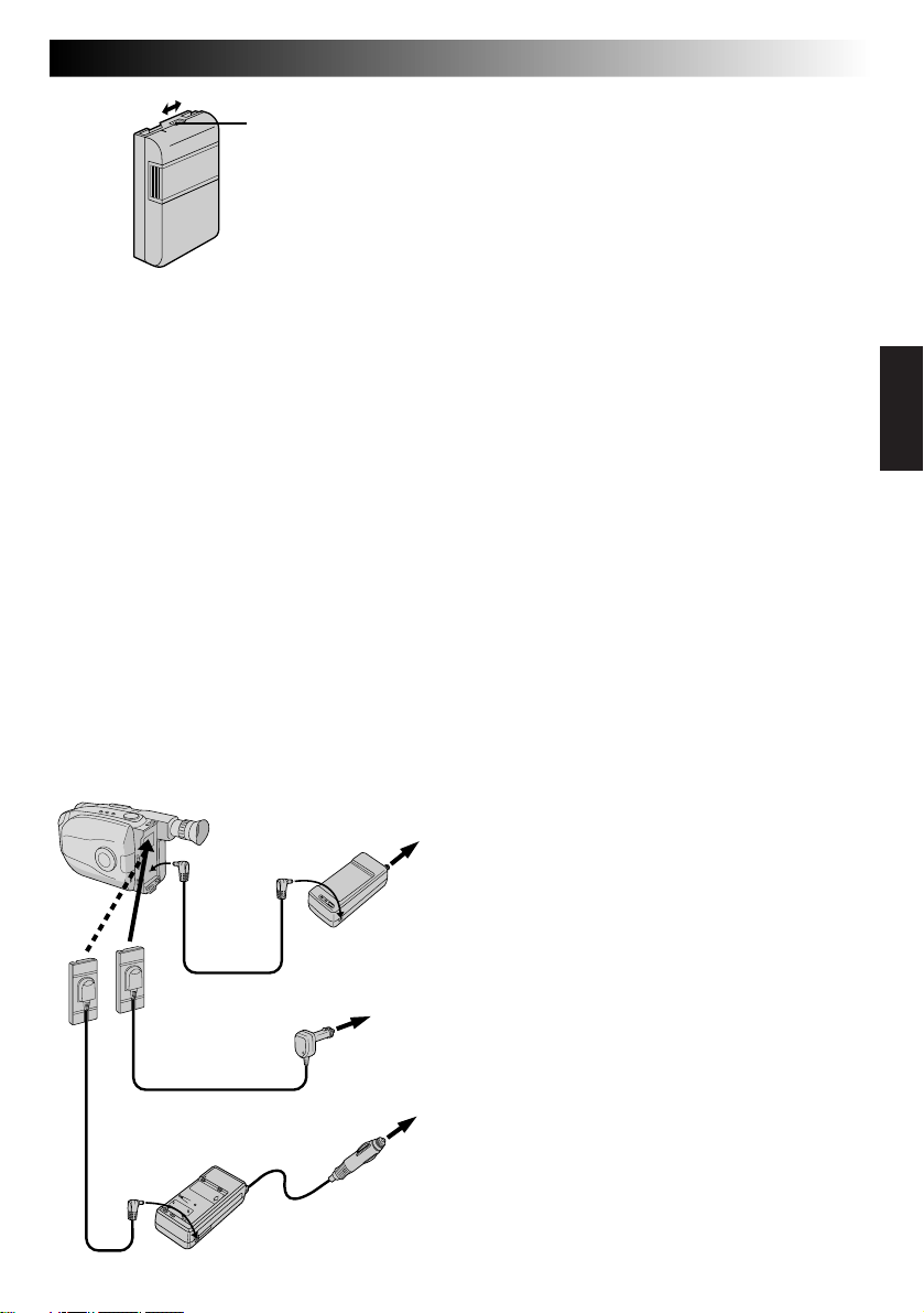
DC OUT
terminal
To DC
IN jack
DC cord
Car Battery Cord
AP-V7U (optional)
Car Battery
Charger/Adapter
BH-V3U (optional)
To AC outlet
AC Power Adapter/
Charger AA-V15U
To car’s
cigarette
lighter socket
USING A CAR BATTERY
Use the optional Car Battery Cord or Car Battery
Charger/Adapter (connect as shown in the
illustration to the left).
NOTES:
●
When using the car battery, leave the engine
idling.
●
The optional Car Battery Charger (BH-V3U) can
also be used to charge the battery pack.
●
When using the optional Car Battery Charger or
Car Battery Cord (AP-V7U), refer to the respective
instruction booklet.
USING AC POWER
Use the AC Power Adapter (connect as shown in
the illustration to the left).
NOTE:
The supplied AC Power Adapter/Charger features
automatic voltage selection in the AC range from
110 V to 240 V.
Page 10
10 EN
GETTING STARTED
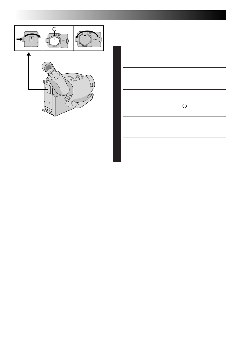
A
Clock (Lithium) Battery Insertion/Removal
This battery is necessary for clock operation and to
perform date/time settings.
SWITCH OFF POWER
Switch off the unit’s power and remove the power
1
supply unit.
OPEN COVER
Open the clock battery compartment cover while
2
pressing the release tab.
REMOVE BATTERY (when replacing)
Insert a pointed, non-metallic object between the
3
battery and the compartment (A) and pull the
battery out.
INSERT BATTERY
Ensure that the plus (+) side is up and insert a
4
CR2025 lithium battery and push it in.
CLOSE COVER
Close the compartment cover until it clicks in place.
(cont.)
5
NOTE:
See “SAFETY PRECAUTIONS” (Z pg. 2) for information
on safe handling of lithium batteries.
Page 11
Select Dial
MENU
Jog Dial
Viewfinder
MENU
4
MENU END
FOCUS
EXPOSURE
DATE TIME
TELE MACRO
TAPE LENGTH
M. W. B.
ZOOM SPEED
4
NEXT
Menu Screen
YEAR
MONTH
DAY
TIME
EXIT
DATE/TIME Setting Menu
4
MENU END
FOCUS
EXPOSURE
DATE TIME
TELE MACRO
TAPE LENGTH
M. W. B.
ZOOM SPEED
4
NEXT
DATE TIME
PM 12: 00
MENU
AUTO
AUTO
JAN
OFF
T30
AUTO
FAST
1998
JAN
AUTO
AUTO
DEC
OFF
T30
AUTO
FAST
1. 98
1
25. 98
12-hour
indication with
AM or PM
EN 11
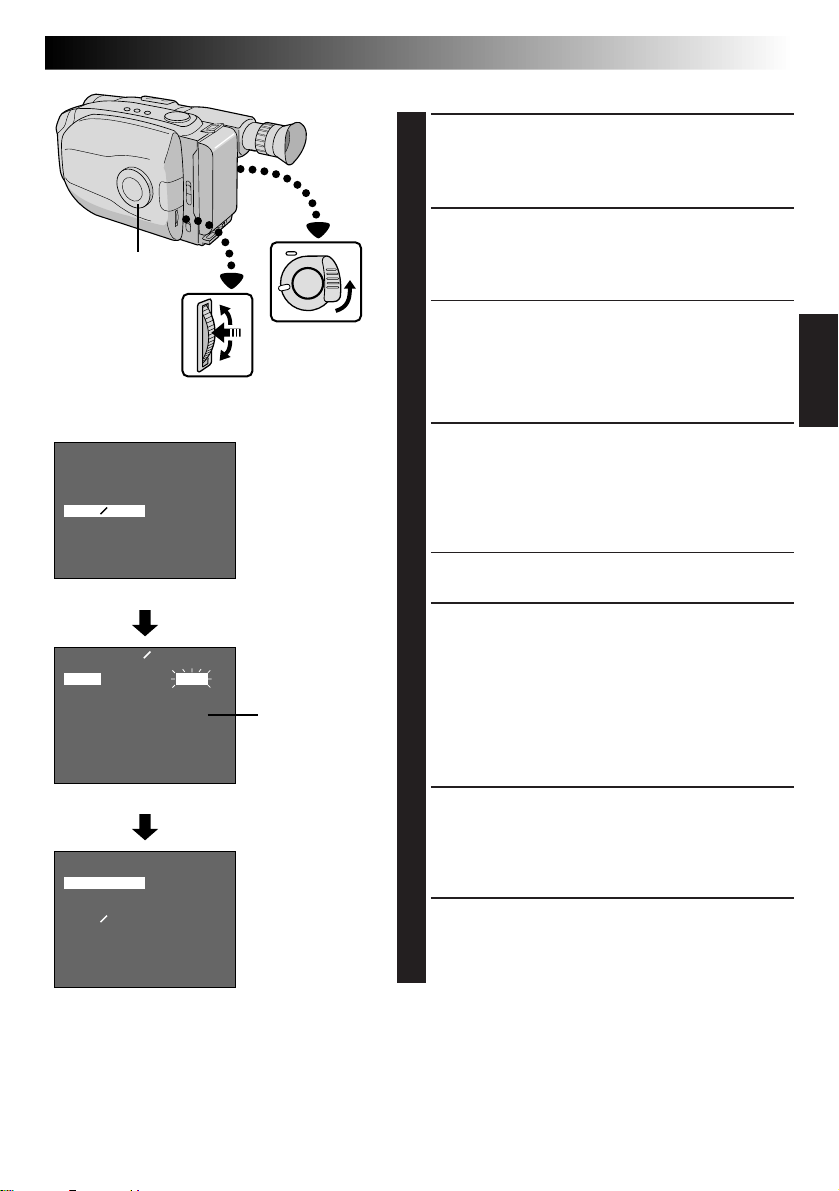
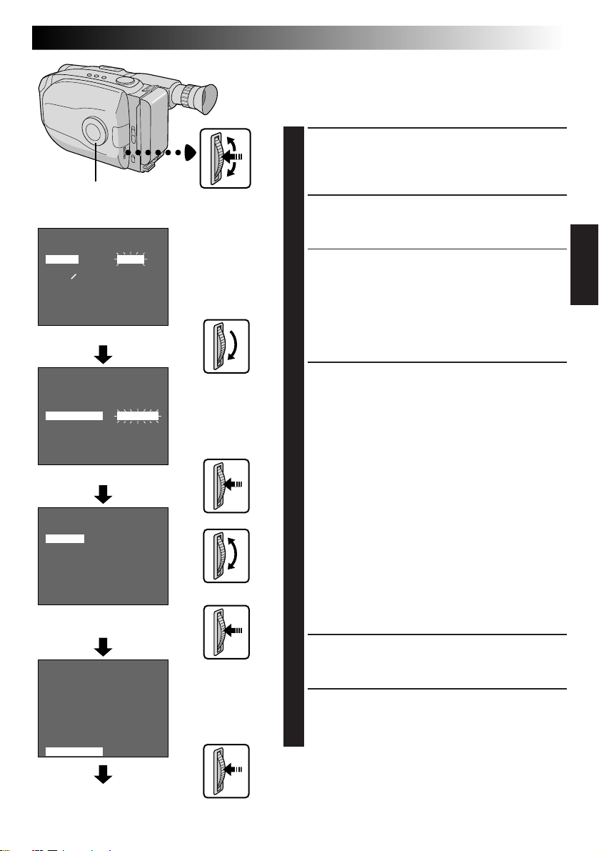
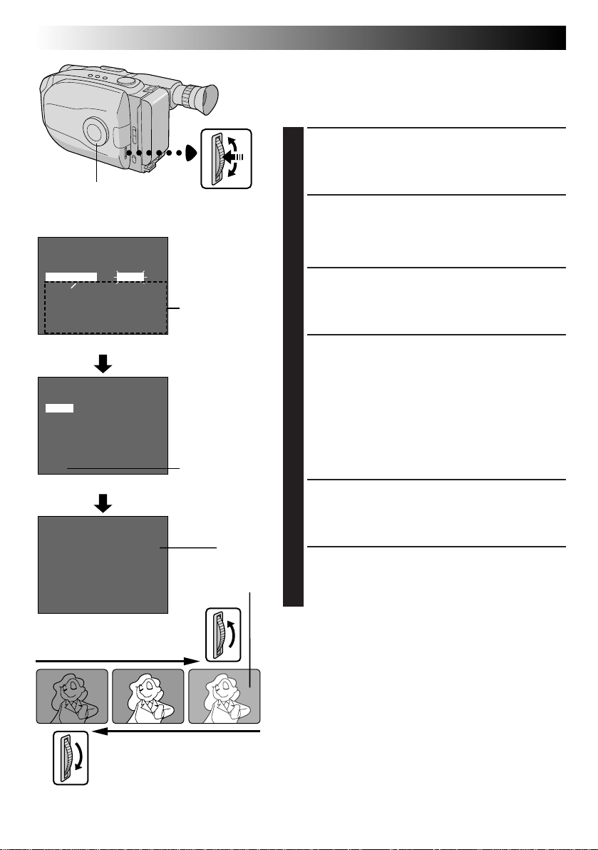
Date/Time Setting
ACCESS MENU SCREEN
First set the Power Switch to “CAMERA”. Turn the
1
Select Dial to any position except AUTO LOCK,
then press the MENU Jog Dial.
SELECT FUNCTION
Rotate the MENU Jog Dial to move the highlight bar
2
to “DATE/TIME”, then press it. The DATE/TIME
Setting Menu appears.
•If you decide you want to return the date and time
to the previous settings, rotate the MENU Jog Dial
to move highlight bar to “EXIT” and press it, then
go to step 6.
•If you want to set only the time without changing
the date, go to step 4.
SET DATE
Rotate the MENU Jog Dial to move the highlight bar
3
to the item you want to set and then press it. When
the setting begins blinking, rotate the MENU Jog
Dial until the correct setting appears and then press
it. The setting stops blinking.
•Repeat this procedure until you’re satisfied with
the Date settings (“YEAR”, “MONTH” and “DAY”).
SET TIME
Rotate the MENU Jog Dial to move the highlight bar
4
to “TIME” and then press it. When the hour setting
begins blinking, rotate the MENU Jog Dial until the
correct setting appears and then press it. When the
hour setting stops blinking and the minute setting
begins blinking, rotate the MENU Jog Dial until the
correct setting appears and then press it. The minute
setting stops blinking.
START CLOCK OPERATION
When none of these settings (YEAR, MONTH, DAY,
5
TIME) blinks, rotate the MENU Jog Dial to move the
highlight bar to “EXIT”, and press it. The Menu
Screen appears and “MENU END” is highlighted.
CLOSE MENU
Press the MENU Jog Dial.
6
NOTE:
To display the date and time in the viewfinder and on a
connected TV, see “Date/Time Insert” (
Z
pg. 20).
Page 12
12 EN
SP/EP Recording
Mode Button
Select Dial
MENU Jog Dial
GETTING STARTED
(cont.)
Recording Mode Setting
Set depending on your preference.
SET RECORDING MODE
First set the Power Switch to “CAMERA”. Press SP/EP
1
Button for more than 1 second. “SP” (Standard Play)
provides higher picture and sound quality and is
better for dubbing, while “EP” (Extended Play) is
more economical, providing three times as the
recording time.
NOTE:
If the recording mode is switched during recording, the
playback picture will be blurred at the switching point.
Viewfinder
SP
MENU
4
MENU END
FOCUS
EXPOSURE
DATE TIME
TELE MACRO
TAPE LENGTH
M. W. B.
ZOOM SPEED
4
NEXT
Menu Screen
TAPE LENGTH
T20
T30
T40
EXIT
TAPE LENGTH Setting Menu
MENU
4
MENU END
FOCUS
EXPOSURE
DATE TIME
TELE MACRO
TAPE LENGTH
M. W. B.
ZOOM SPEED
4
NEXT
AUTO
AUTO
DEC
OFF
T40
AUTO
FAST
AUTO
AUTO
DEC
OFF
T20
AUTO
FAST
T40
25.98
25.98
Tape length
indicator
Recording
mode
indicator
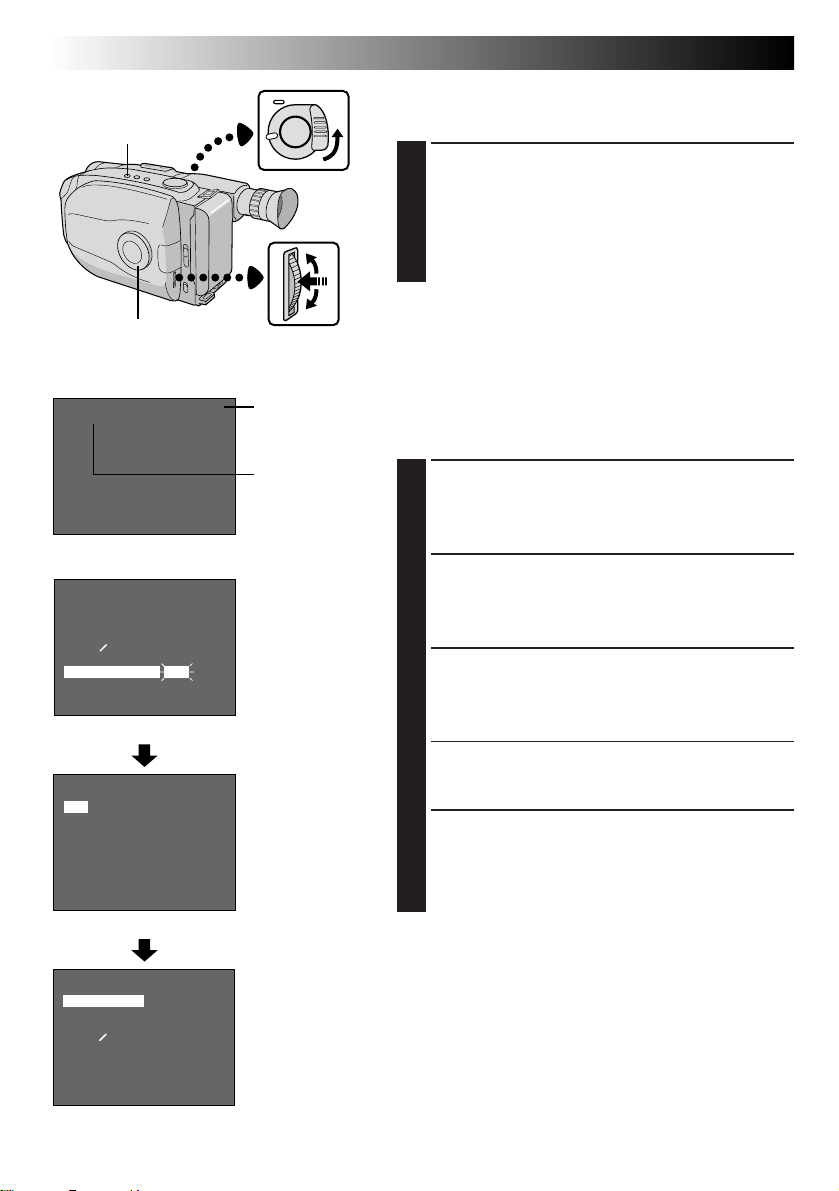
Tape Length Setting
Set the tape length according to the length of the tape
used.
ACCESS MENU SCREEN
First set the Power Switch to “CAMERA”. Turn the
1
Select Dial to any position except AUTO LOCK,
then press the MENU Jog Dial.
SELECT FUNCTION
Rotate the MENU Jog Dial to move the highlight bar
2
to “TAPE LENGTH”, then press it. The TAPE
LENGTH Setting Menu appears.
SET TAPE LENGTH
Rotate the MENU Jog Dial to move the highlight bar
3
to the correct setting. T20=20 minutes of recording
time, T30=30 minutes, and T40=40 minutes (in SP).
•If you decide you want to return the tape length to
the previous setting, rotate the MENU Jog Dial to
move the highlight bar to “EXIT”.
CLOSE MENU
Press the MENU Jog Dial. The Menu Screen
4
reappears and the highlight bar is on “MENU END”.
Then press the MENU Jog Dial again to close the
Menu Screen.
NOTES:
●
The displayed tape remaining time (Z pg. 17) is
correct only if the correct tape length has been
selected.
●
Once you have set the tape length, it remains unchanged even if the Select Dial is returned to AUTO
LOCK.
Page 13
1
3
3
Erase Protection Gear
2
2
Turn to take
up slack.
EN 13
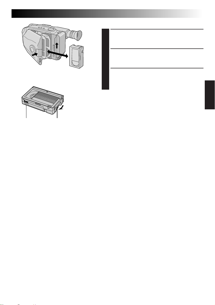
Loading/Unloading A Cassette
OPEN CASSETTE HOLDER
Slide EJECT until the holder opens. Do not use force
1
to open.
INSERT/REMOVE CASSETTE
Make sure the label is facing outward.
2
CLOSE CASSETTE HOLDER
Press PUSH and make sure the holder is closed and
3
locked.
NOTES:
●
A cassette holder can’t be opened unless a power
supply is attached.
●
Make sure that the tape is not slack when loading the
cassette. If there is any slack, turn the gear on the
cassette in the direction of the arrow to take up the
slack.
●
Make sure the Erase Protection tab is in the position
that allows recording. If not, slide the tab. Some
cassettes have removable tabs. If the tab has been
removed, cover the hole with adhesive tape.
●
The cassette holder can’t be opened while the
camcorder is in the record mode.
Page 14
14 EN
Recording Start/Stop Button
Power Zoom Button
GETTING STARTED
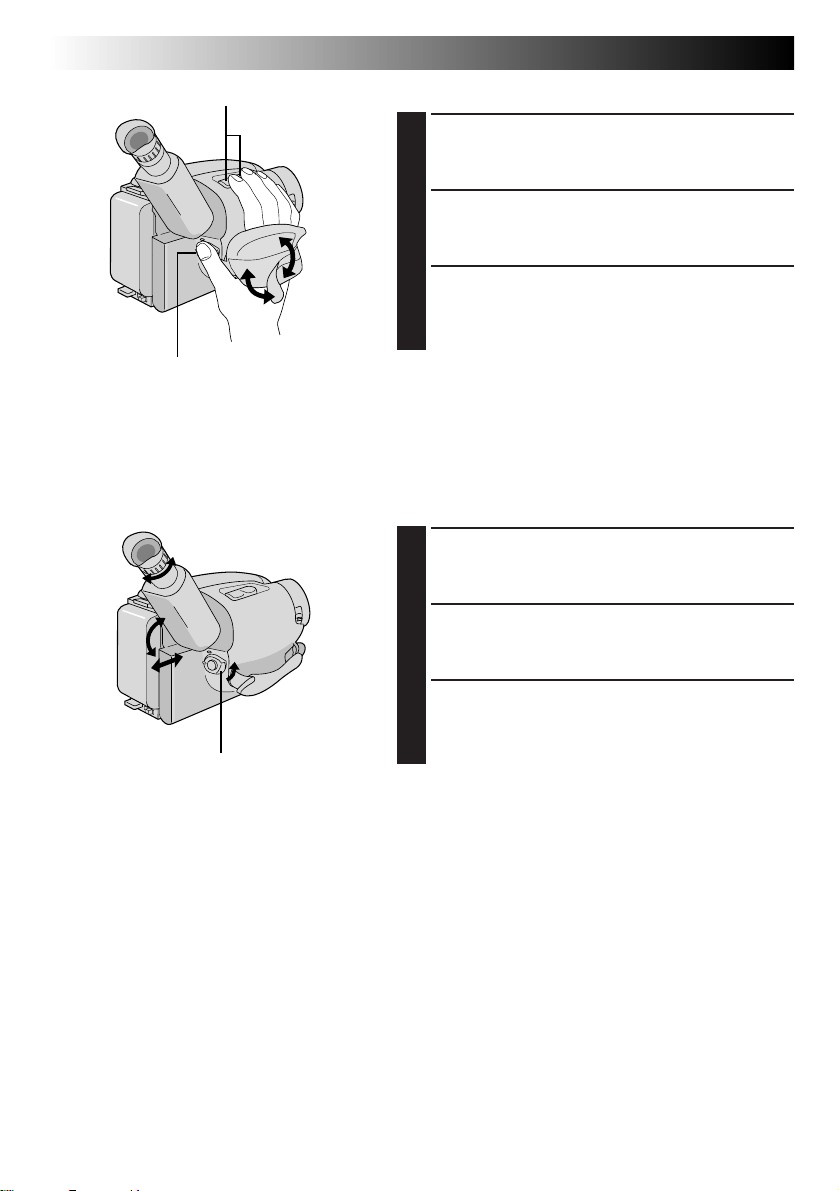
Grip Adjustment
EXPAND LOOP
Separate the Velcro strip.
1
INSERT HAND
Pass your right hand through the loop and grasp the
2
grip.
ADJUST STRAP LENGTH
Adjust so your thumb and fingers can easily operate
3
the Recording Start/Stop Button and Power Zoom
Button. Refasten the Velcro strip.
Viewfinder Adjustment
(cont.)
3
1
1
2
2
Set POWER to “CAMERA”.
POSITION VIEWFINDER
Adjust the viewfinder manually for best viewability
1
(see illustration at left).
SELECT MODE
Set the Power Switch to CAMERA.
2
ADJUST DIOPTER
Turn the Diopter Adjustment Control until the
3
indications in the viewfinder are clearly focused.
Page 15
2
1
1
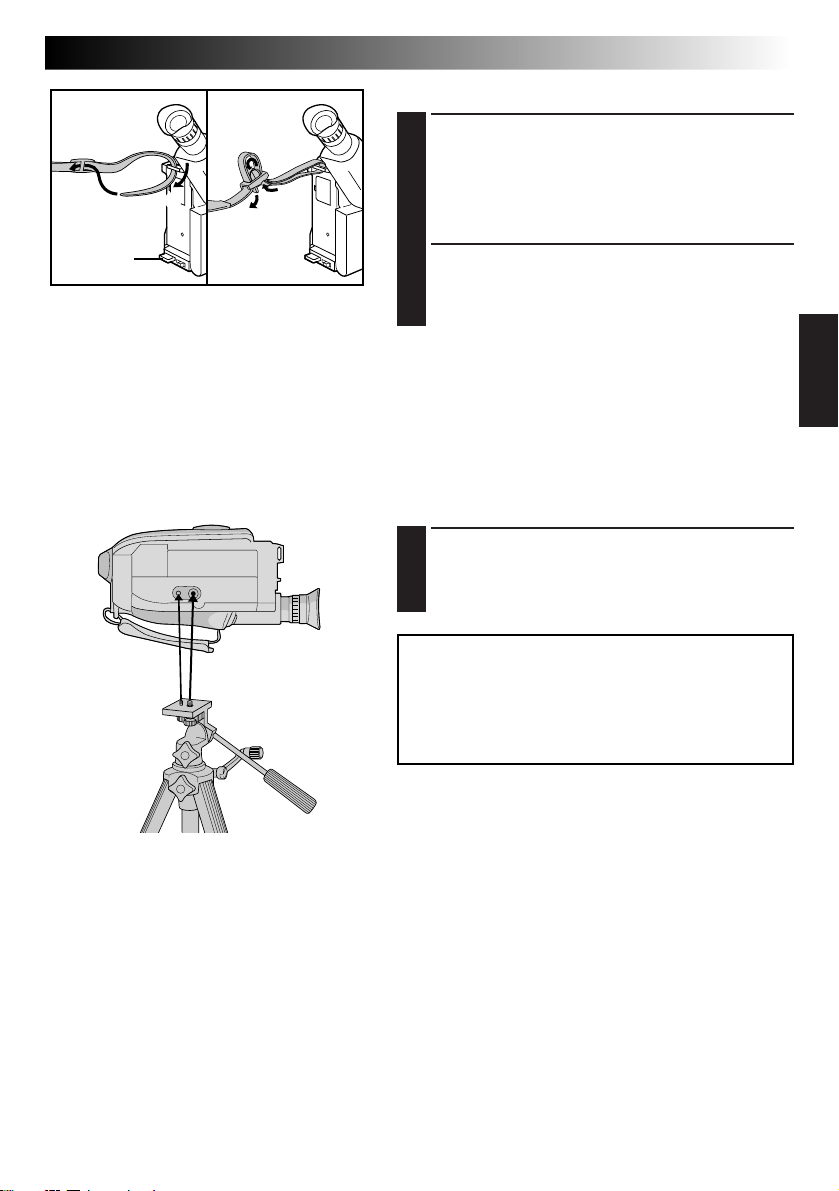
Shoulder Strap Attachment
ATTACH STRAP
Following the illustration at left, thread the strap
1
through the top of the eyelet 1, then fold it back
and thread it through the buckle 2. Repeat the
procedure to attach the other end of the strap to the
other eyelet 3, making sure the strap isn’t twisted.
EN 15
3
ADJUST LENGTH
Adjust as shown in the illustration at left 1.
2
Tripod Mounting
ALIGN AND TIGHTEN
Align the screw and camera direction stud on the
1
tripod with the camera’s mounting socket and stud
hole. Then tighten the screw.
CAUTION:
When using a tripod, be sure to open and extend
its legs fully to stabilize the camcorder. To
prevent damage to the unit caused by falling
over, do not use a small-sized tripod.
Page 16
16 EN
LENS COVER Switch
RECORDING
Basic Recording
NOTE:
You should already have performed the procedures listed
below. If not, do so before continuing.
●
Power (Z pg. 8)
●
Recording Mode/Tape Length Setting (Z pg. 12)
●
Grip Adjustment (Z pg. 14)
Power Switch
Start/Stop Button
Tally lamp
(lights while recording
is in progress)
Power
indicator
LOAD A CASSETTE
Slide EJECT to open the cassette holder, then insert
1
the cassette with the label facing out. Press PUSH to
ensure the holder is closed and locked.
ENTER RECORD-STANDBY MODE
Slide the LENS COVER Open/Close Switch to open
2
the lens cover, then set the Power Switch to
CAMERA.
•The power indicator lights and the camcorder
enters the Record-Standby mode.
•The scene you’re aimed at appears on the
viewfinder screen, with the word “PAUSE”
superimposed upon it.
START SHOOTING
Press the Recording Start/Stop Button.
3
REC
•“
” appears in the viewfinder while recording is
in progress.
Page 17
Tape remaining time indicator
25MIN
(Now calculating)
120MIN
119MIN
Start/Stop Button
MIN
3MIN
2MIN
(Blinking)
1MIN
(Blinking)
0MIN
(Blinking)
EN 17
STOP RECORDING
Press the Recording Start/Stop Button again to stop
4
recording.
•The camcorder re-enters the Record-Standby
mode.
NOTES:
●
A cassette holder can’t be opened unless a power supply
is attached.
●
There may be a delay after you slide EJECT until the
holder opens. Do not use force.
●
The displayed remaining time is approximate.
●
The time required to calculate the remaining tape
length, and the accuracy of the calculation, may vary
according to the type of tape used.
●
The tape remaining time indicator is correct only if the
correct tape length has been selected (Z pg. 12).
●
“TAPE END” appears when the tape reaches its end,
and the power goes off automatically if left in this
condition for 5 minutes. “TAPE END” also appears
when a cassette whose tape is already at its end is
loaded.
●
If the Record-Standby mode continues for 5 minutes
without performing Zoom or any other operations, the
camcorder’s power shuts off automatically. Set the
Power Switch to “POWER OFF”, and then back to
“CAMERA” to turn the camcorder on again.
●
If the Recording Start/Stop Button is pressed after the
Record-Standby mode has continued for over
5 minutes, recording may not start immediately.
●
If you’re recording on a cassette from the middle (such
as when a tape is removed and re-inserted during
recording), use the Retake function (Z pg. 19) to find
the end of the last recording so you don’t erase any of
it.
●
The LENS COVER warning blinks for about 5 seconds
when the camcorder is turned on when the cover is
closed.
Page 18
18 EN
RECORDING
Basic Features
Zoom-in
Power Zoom button
Select Dial
4
MENU END
FOCUS
EXPOSURE
DATE TIME
TELE MACRO
TAPE LENGTH
M. W. B.
ZOOM SPEED
4
NEXT
FAST
SLOW
Zoom indicator bar
Zoom Level
indicator
Viewfinder
MENU
AUTO
AUTO
JAN
OFF
T30
AUTO
FAST
Menu Screen
ZOOM SPEED
Zoom-out
MENU Jog Dial
1.98
FEATURE: Zooming
PURPOSE: To produce the zoom in/out effect, or
OPERATION:
NOTES: ●
an instantaneous change in image
magnification.
Digital circuitly doubles the maximum
22x magnification offered by optical
zoom. This system is called Digital Zoom.
Zoom In
Press the “T” of the Power Zoom Button.
Zoom Out
Press “W” of the Power Zoom Button.
n Zooming speed is available. A total of
4 zoom speeds are available. 2 speeds
can be selected depending on how
hard the Power Zoom Button is
pressed (press the button fully for
regular-speed, press it lightly for slowspeed), while 2 speed levels (FAST/
SLOW) can be selected in the ZOOM
SPEED Menu depending on the overall
speed you prefer.
The combinations of zoom speeds are
shown in the chart below.
Changing the ZOOM SPEED in the
Menu
1) Set the Select Dial to any position
except AUTO LOCK and press the
MENU Jog Dial. The Menu Screen
appears.
2) Rotate the MENU Jog Dial to move
the highlight bar to “ZOOM SPEED”,
then press it. The ZOOM SPEED
Setting Menu appears.
3) Rotate the MENU Jog Dial to move
the highlight bar to the desired speed
and press it twice. The Menu Screen
disappears and setting is completed.
Focusing may become unstable
during Zooming. In this case, set the
zoom while in Record-Standby, lock
the focus by using the manual focus
Z
pg. 31), then zoom in or out in
(
Record mode.
●
The zoom level indicator (5) moves
during zoom. Once the zoom level
indicator reaches the top of the zoom
indicator bar, all magnification from
that point is through digital
processing.
●
During Digital Zoom, the quality of
image may suffer. To deactivate Digital
Zoom, set “D.ZOOM” to “OFF” in the
Menu Screen (
Z
pg. 29).
EXIT
ZOOM SPEED Setting Menu
Zooming Speed ( 1 – 4 in order of speed)
“ZOOM SPEED”
in the Menu
Screen
FAST 1 (fastest) 3
SLOW 2 4 (slowest)
Pressing the Power Zoom Button
fully lightly
: when the Select Dial is set to AUTO LOCK.
Page 19
P. STABILIZER
RETAKE (R/F)
EN 19
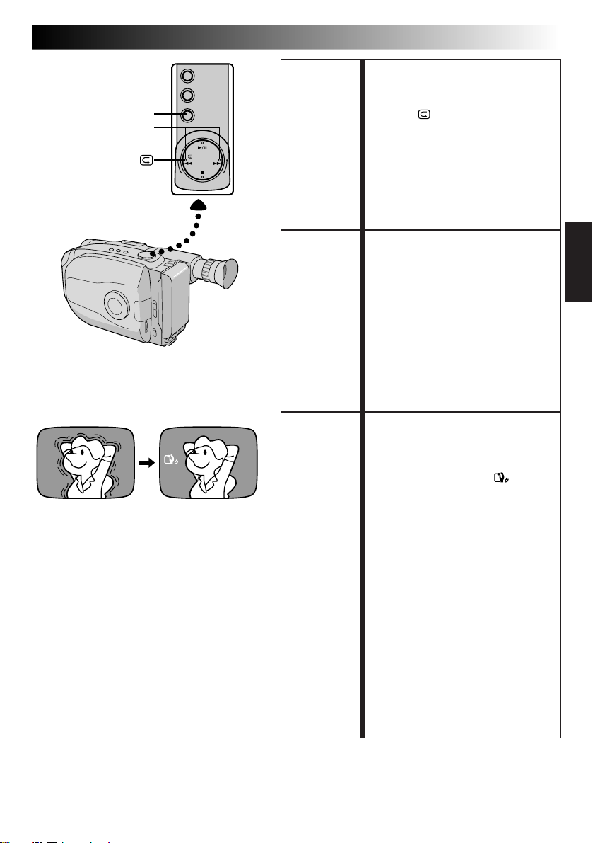
FEATURE: Quick Review
PURPOSE: To check the end of the last
OPERATION: 1) Press “ ” and release quickly
NOTE:
FEATURE: Retake
PURPOSE: To re-record certain segments.
OPERATION: 1) Make sure the camcorder is in the
NOTE:
FEATURE: Picture Stabilizer
PURPOSE: To compensate for unstable images
OPERATION: 1) Press P. STABILIZER. “
NOTES: ●
recording.
during the Record-Standby mode.
n Tape is rewound for about 2
seconds and played back
automatically, then pauses in
Record-Standby mode for the
next shot.
Distortion may occur at start of
playback. This is normal.
Record-Standby mode.
2) Press either RETAKE button to
reach the start point for new
recording. Pressing “F” forwards
the tape and pressing “R” reverses
it.
3) Press Recording Start/Stop Button
to start recording.
Noise may appear during Retake.
This is normal.
caused by camera-shake, particularly
at high magnification.
n To switch off the Picture
Stabilizer, press P. STABILIZER.
The indicator disappears.
”appears.
Accurate stabilization may not be
possible if hand shake is excessive,
or under the following conditions:
•
When shooting subjects with
vertical or horizontal stripes.
•
When shooting dark or dim
subjects.
•
When shooting subjects with
excessive backlighting.
•
When shooting scenes with
movement in various directions.
•
When shooting scenes with lowcontrast backgrounds.
●
Switch off the Picture Stabilizer
when recording with the
camcorder on a tripod.
Page 20
20 EN
DATE/TIME
Select Dial
Date display
Time display
Date/Time display
Auto Date Record mode
Date-off mode (No display)
Date display
Time display
Date/Time display
DEC 25.98
PM10:50:00
Display
Auto Date Record mode
AUTO DATE
Auto date record mode
DEC 25.98
Auto date record
executed
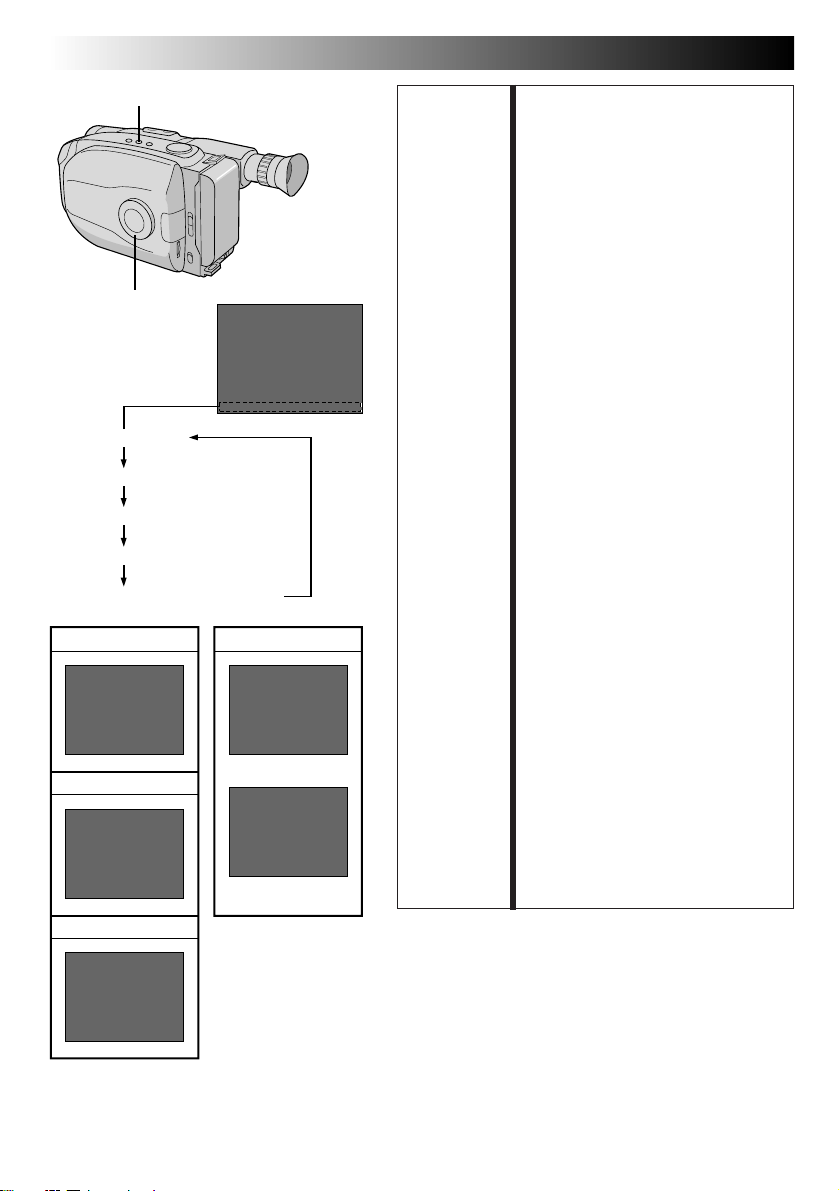
RECORDING
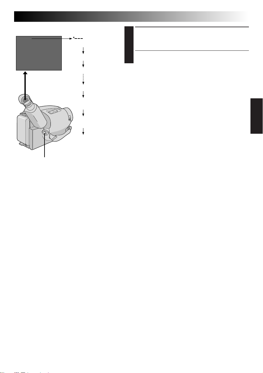
FEATURE: Date/Time Insert
PURPOSE: To display the date and time in the
OPERATION: 1) Turn the Select Dial to any
NOTES:
Basic Features (cont.)
viewfinder or on a connected color
monitor, as well as to record them
manually or automatically.
position except AUTO LOCK.
2) Choose a display mode by
pressing DATE/TIME repeatedly
while in Record-Standby to cycle
through the modes as shown in the
illustration at left.
n You should have already
performed the Date/Time Setting
procedure (Z pg. 11). If you
haven’t, do so first.
DISPLAY
●
The selected display can be
recorded.
●
If you don’t want to record the
display, select the Date-off mode
before shooting.
●
If you want to delete the display
during shooting, press DATE/TIME.
●
To recall the display, engage the
Record-Standby mode and press
DATE/TIME repeatedly until the
desired display appears.
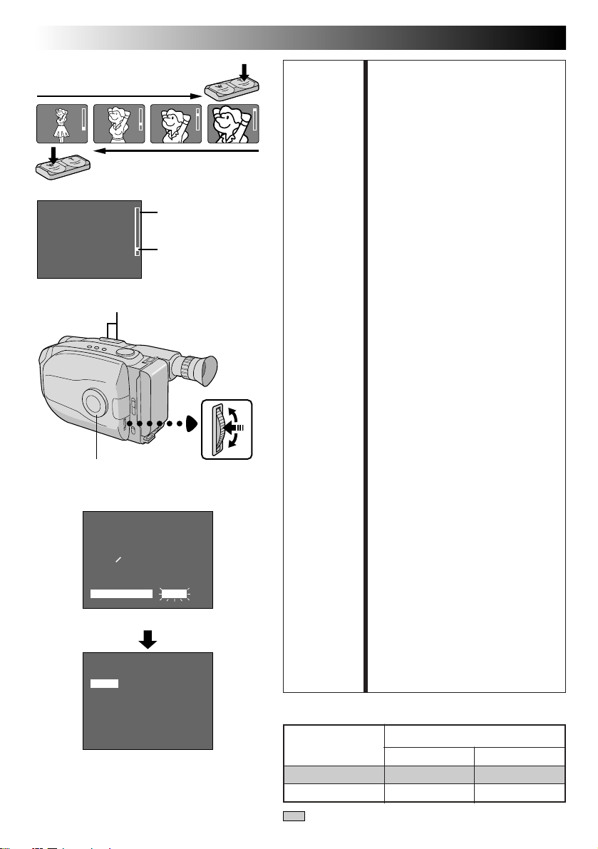
AUTO DATE RECORD
●
Your camcorder automatically
records the date for about 5
seconds after recording is initiated
in the following situations:
•
After changing the date.
•
After loading a cassette.
•
After Auto Date Record mode is
selected by pressing DATE/TIME.
In this mode, the date is replaced
after 5 seconds with “AUTO DATE”
but this is not recorded.
●
Setting the Select Dial to AUTO
LOCK always engages the Auto
Date Record mode, and disables
all other modes.
DEC 25.98
PM10:50:00
Page 21
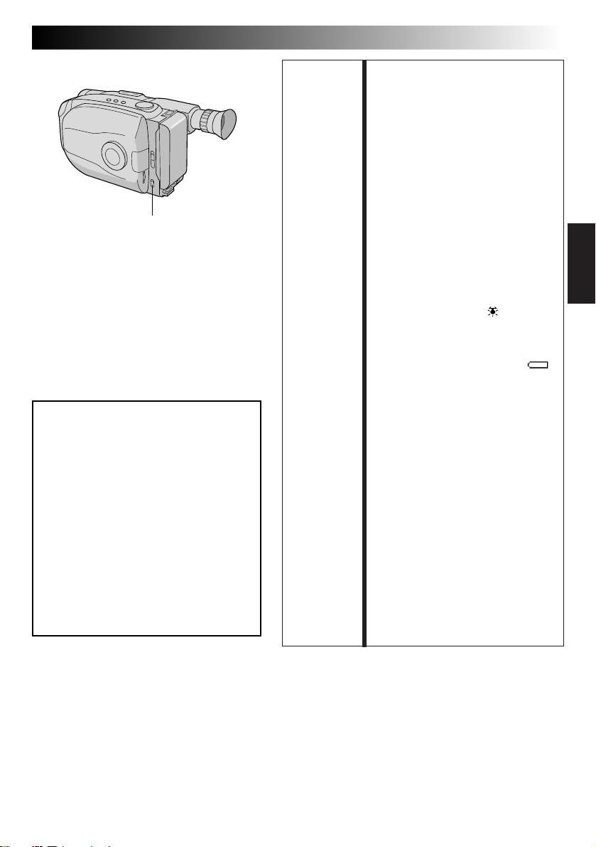
LIGHT OFF/AUTO/ON
DANGER
n The video light can become extremely
hot. Do not touch it either while in
operation or soon after turning it off,
otherwise serious injury may result.
n Do not place the camcorder into the
carrying case immediately after using
the video light, since it remains
extremely hot for some time.
n When operating, keep a distance of
about 30 cm. (1 ft.) between the video
light and people or objects.
n Do not use near flammable or explosive
materials.
n It is recommended that you consult your
nearest JVC dealer for replacing the
video light.
EN 21
FEATURE: Video Light
PURPOSE: To brighten the scene when natural
OPERATION: 1) Set the LIGHT OFF/AUTO/ON
NOTES: ●
lighting is too dim.
Switch as required:
ON : Always keeps the light on
AUTO : Automatically turns on
OFF : Turns off the light.
n The video light can only be used
n It is recommended to set the
n When not using the video light,
as long as the camcorder
is turned on.
the light when the
camcorder senses
insufficient lighting on the
subject.
with the camcorder’s power on.
white balance (Z pg. 33) to
HALOGEN mode ( ) when you
use the video light.
turn it off to save battery power.
Even if the battery indicator ( )
does not blink if the battery pack’s
charge is low, the camcorder may
turn off automatically when you
turn on the video light, or when
you start recording with the video
light turned on.
●
When the LIGHT OFF/AUTO/ON
Switch is set to “AUTO”:
•
Depending on the lighting
conditions, the video light may
keep turning on and off. In this
case, manually switch the light
on or off using the LIGHT OFF/
AUTO/ON switch.
•
While the Sports or High-Speed
Shutter mode (Z pg. 23) is
engaged, the light is likely to stay
on.
•
While the Twilight mode
(Z pg. 23) is engaged, the light
will not activate.
Page 22
22 EN
1 second later, the mode is activated.
SEPIA
Viewfinder
Select Dial
After 1 sec.
1
C
O
L
U
A
0
0
0
2
/
EFFECT
WIDE TITLE
SUPER
LOLUX
Mark
K
T
O
M
RECORDING
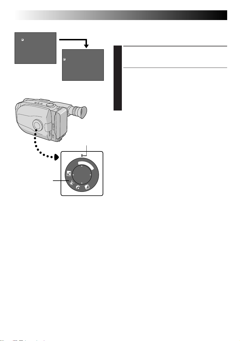
Advanced Features
Program AE With Special Effects
All you have to do to access any of the variety of
shooting effects is to turn the Select Dial.
SELECT MODE
Turn the Select Dial until the symbol of the function
1
you want is aligned with the mark.
•The selected mode’s name and its indication are
displayed for approx. 1 second. Then the name
disappears, and only the indication remains. The
mode is activated.
•When Auto Mode Lock or Auto Mode Release
mode is selected, only the mode’s name is
displayed. Then the name disappears and the
mode is activated.
NOTES:
●
Only one effect can be engaged at a time.
●
The screen becomes slightly reddish when the Fade/
Wipe (Z pg. 24) is used in the Sepia mode.
●
The screen becomes slightly dark in the High Speed
Shutter mode. Use in well-lit situations.
●
In the High Speed Shutter or Sports modes, picture
R
E
L
E
A
O
S
D
E
E
F
G
N
D
color may be adversely affected if subject is lit by
alternating discharge-type light sources such as
flourescent or mercury-vapor lights.
Page 23
Dial Viewfinder
symbol indication
Mode
Dial Viewfinder
symbol indication
EN 23
Mode
LOCK AUTO LOCK
Auto Mode Lock
Auto Mode Lock
Locks the camcorder in Full Auto mode, preventing
incorrect operation due to accidental button
pressing during shooting.
•In this mode the following controls are disabled;
DATE/TIME display select, and the Menu Jog Dial.
RELEASE AUTO RELEASE
Auto Mode Release
Auto Mode Release
Re-enables the controls that were disabled by Auto
Mode Lock.
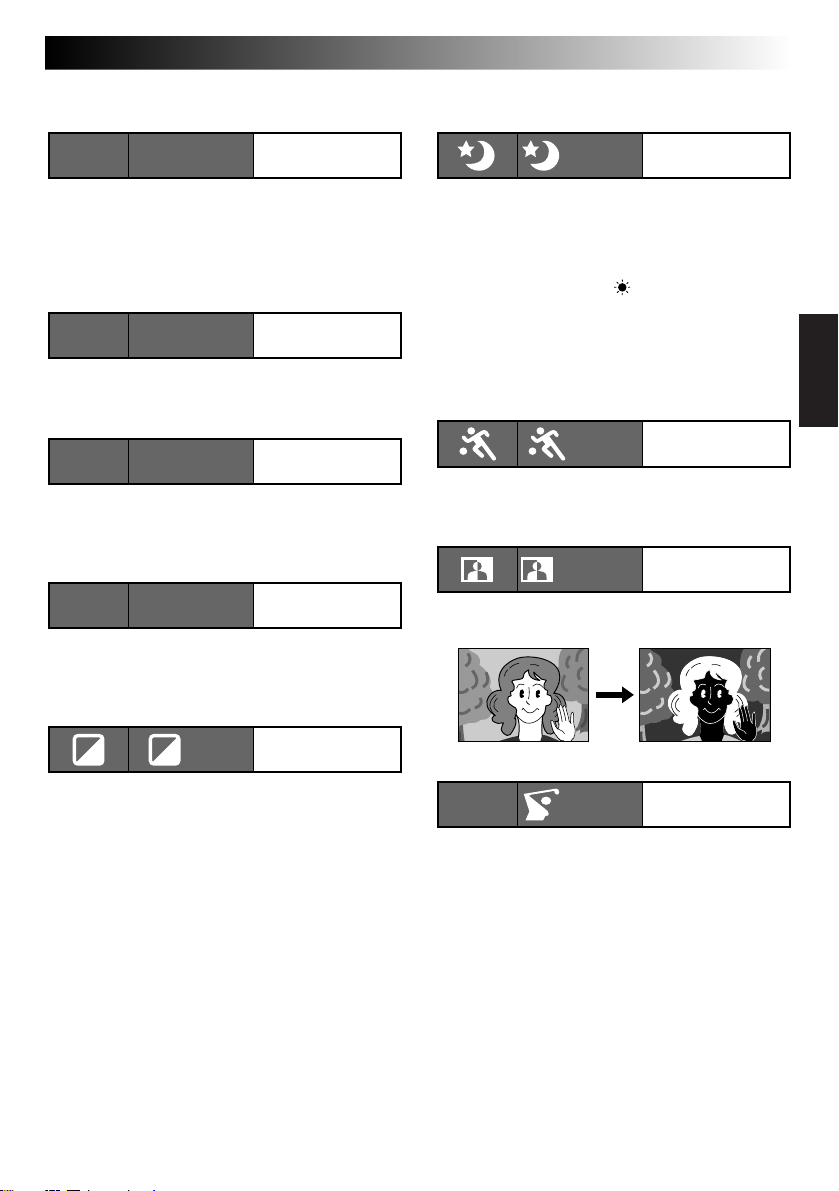
FG FG : FOG
Electronic
Fog Filter
Electronic Fog Filter
Makes the picture look misty white, as when an
external fog filter is attached to the lens. Softens the
image and gives it a “fantasy” look.
ND ND:ND EFFECT
ND Effect
ND Effect
A black mist darkens the picture, as when an ND
filter is used. Helps to counter the effects of glare on
the subject.
TWILIGHT
Twilight
Twilight
Dusk, twilight scenery, fireworks, etc., look more
natural and dramatic. The following happens when
Twilight mode is selected:
•Auto gain control is turned off.
•White Balance is set to “ ” (FINE day mode), but
can also be manually changed to another mode
(Z pg. 33).
•Auto Focus becomes available only in the range of
10 m (33 ft.) to infinity. To focus when the subjectto-camera distance is less than 10 m (33 ft.), use
manual focusing (Z pg. 31).
SPORTS
Sports
Sports
High shutter speed clearly captures fast-moving
action.
NEGA POSI
Nega/Posi
Nega/Posi (Negative/Positive)
The colors of a picture are reversed.
SEPIA
Sepia
Sepia
The scene being shot is recorded in sepia-tinted
(reddish-brown) monochrome, giving the effect of
an older movie. Use together with Wide (Z pg. 25)
for the authentic look of a classic Hollywood
movie.
NEGA POSI mode
1/2000 S 1/2000
2
1/2000 sec.
High Speed Shutter
High-Speed Shutter (1/2000s.)
Captures faster action than Sports mode.
Page 24
24 EN
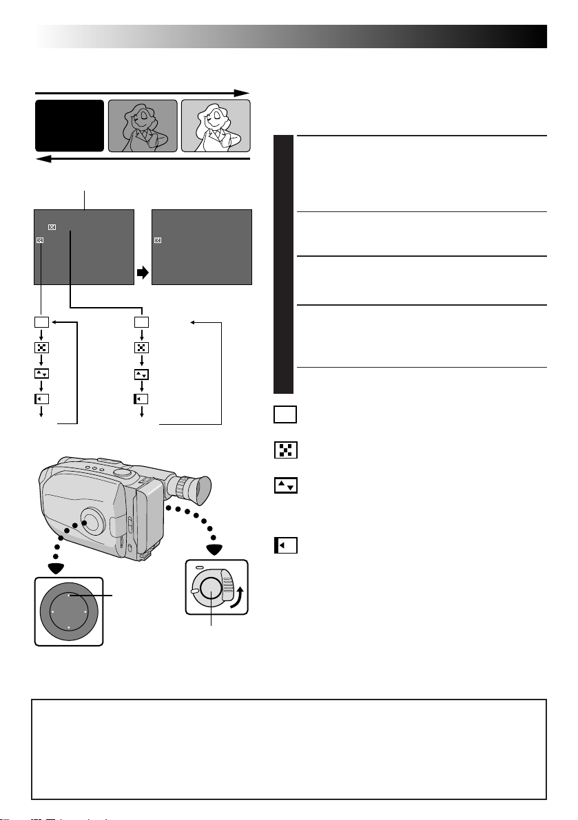
[Ex. : Fader]
Fade-in
Function indication
4
EFFECT
MOSAIC
B
K
OFF
(No indication)
Viewfinder
After 2 sec.
B
K
FADER
MOSAIC
SHUTTER
SLIDE
OFF
EFFECT
Fade-out
Recording
Start/Stop
Button
RECORDING
Advanced Features (cont.)
Fade/Wipe
These effects let you make pro-style scene transitions.
Fade- or wipe-in works at recording start, and fade- or
wipe-out works at recording end or when you enter
Record-Standby mode.
ENGAGE FADE- OR WIPE-STANDBY
MODE
Press EFFECT to cycle through the modes as shown at
left. Once the desired mode appears, it is selected and
1
reserved.
•The selected mode’s name and its indication are
displayed for approx. 2 seconds. Then the name
disappears, and only the indication remains.
START OR END RECORDING
Press Recording Start/Stop Button to activate fade-in/out
or wipe-in/out.
2
TO CANCEL FADE- OR WIPESTANDBY MODE
Press EFFECT repeatedly until “OFF” appears.
3
•“OFF” is displayed for approx. 2 seconds and the
fade/wipe standby mode is canceled.
Fader
B
K
Fades in/out to a black screen.
Mosaic (Fader)
Gradually turns/returns the picture into/from a mosaic pattern.
Shutter (Wipe)
A black screen moves in from the top and bottom, closing
over the image like a shutter, or a new image pushes open
the black screen vertically from the center.
Slide (Wipe)
A black screen moves in from the left to gradually cover the
image, or a new image moves in from right to left.
NOTES:
●
Pressing and holding the Recording Start/Stop Button
allows you to record a black blank screen or a mosaic
pattern if Mosaic Fader is selected.
●
The screen becomes slightly reddish when the Fade/Wipe is
used with Sepia (
●
With the Electronic fog filter mode (Z pg. 23) engaged,
when Fader (not Mosaic) is used, the image fades in/out to
a white screen.
Z
pg. 23).
NOTE (for Fade/Wipe, Wide, Super LoLux, Instant Titles and Picture Stabilizer):
When the Select Dial is turned to AUTO LOCK, the above functions will be set to the Factory settings (Fade/
Wipe-standby : “OFF”, Wide mode : off, Super LoLux : “MAX”, Instant Title : off, Picture Stabilizer : off). Then
when the Select Dial is returned to any position except AUTO LOCK, the above functions return to the settings
you selected before turning it to AUTO LOCK. However, if the function is switched during AUTO LOCK, the
selected mode will be set and will remain unchanged even when the Select Dial is turned to any position
except AUTO LOCK.
Page 25
Viewfinder
EN 25
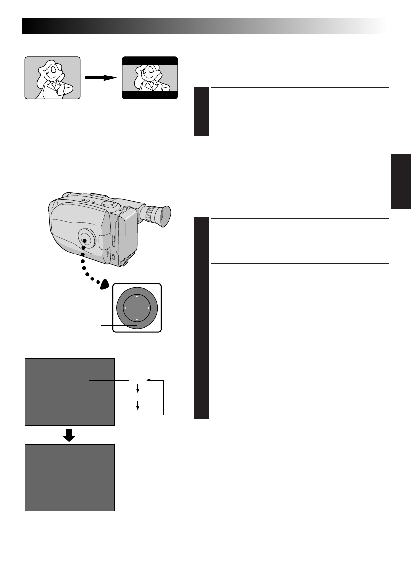
Wide
This feature allows you to record black bars at the top
and bottom of the screen to produce a cinema-like
“wide-screen” effect.
WIDE
SUPER LOLUX
Viewfinder
4
S.LX
MAX
Wide mode
MAX
NORM
OFF
ENGAGE WIDE MODE
Press WIDE.
1
•To restore normal screen, press WIDE again.
Super LoLux(Gain Up)
Bright, natural recordings can be taken even in areas with
low or poor lighting.
SELECT SUPER LOLUX MODE
Press SUPER LOLUX repeatedly to cycle through the
1
modes as shown at left. Once the desired mode
appears, it is engaged.
•The mode’s name is displayed for approx. 2
seconds, then disappears.
MAX : To record a subject in a dark lit environ-
NORM : To record a subject in a dimly lit environ-
OFF : Allows you to shoot dark scenes with no
ment. When it is more convenient to
shoot the subject with a brighter image
even if the picture becomes slightly
coarse.
ment. When it is more convenient to
shoot with a less coarse picture although
the subject becomes slightly dark. This
setting is suitable for measuring sensitivity
conforming to EIA-639 (EIA* Standard for
Low Light Sensitivity Measurement).
*EIA : Electronic Industries Association
picture brightness adjustment.
After 2 sec.
Page 26
26 EN
TITLE
Viewfinder
Title display
HAPPY BIRTHDAY No display
OUR VACATION
MERRY CHRISTMAS
A SPECIAL DAY
RECORDING
Advanced Features (cont.)
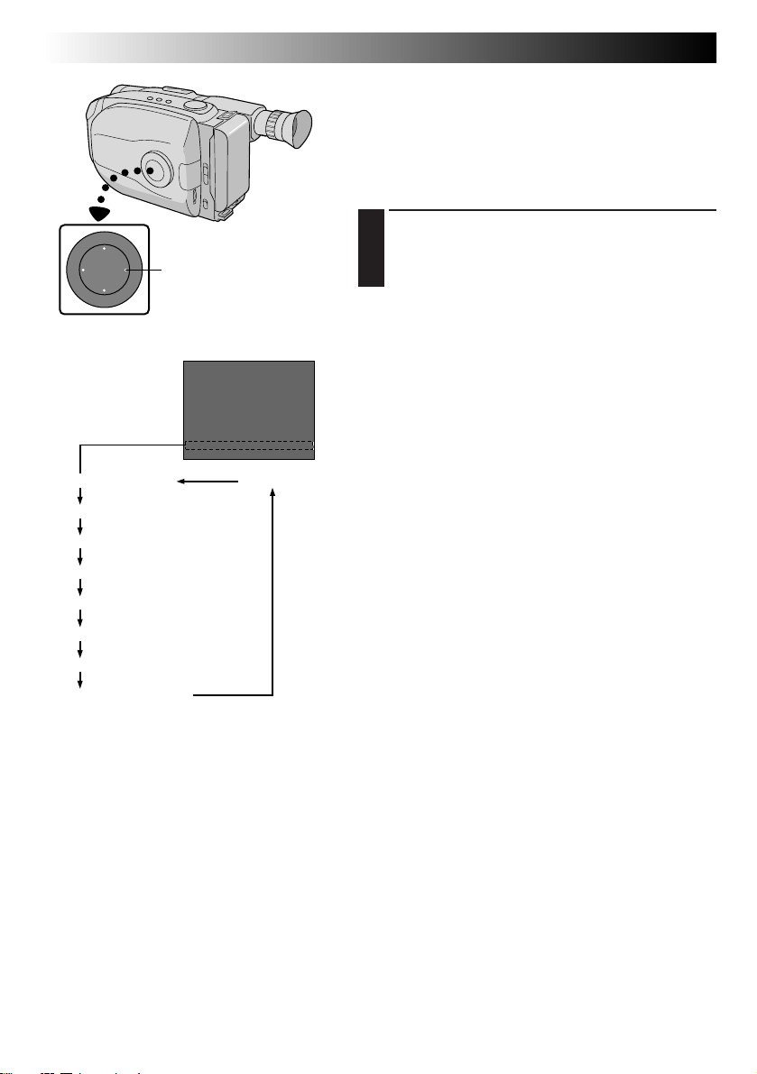
Instant Titles
The camcorder has eight preset titles in memory. You can
superimpose one of them above a previously stored title
as shown in the illustration to the left.
Instant Titles can be displayed not only in English but also
in French, Spanish and Portuguese. Change the setting in
TITLE LANG. in the Menu screen. (Z pg. 27, 29).
SELECT PRESET TITLE
Press TITLE repeatedly to cycle through the preset
1
titles until the desired title is displayed.
HAPPY HOLIDAYS
OUR NEW BABY
WEDDING DAY
CONGRATULATIONS
Page 27
Select Dial
Viewfinder
MENU
4
MENU END
FOCUS
EXPOSURE
DATE TIME
TELE MACRO
TAPE LENGTH
M. W. B.
ZOOM SPEED
4
NEXT
Menu Screen 1
MOVIE MENU
4
BACK
REC TIME
INT. TIME
TALLY LAMP
TITLE LANG.
D. ZOOM
COLOR BAR
JLIP ID NO.
DEMO MODE
4
MENU END
ENGLISH
FRENCH
SPANISH
PORTUGUESE
EXIT
(ex. TITLE LANG.)
4
BACK
REC TIME
INT. TIME
TALLY LAMP
TITLE LANG.
D. ZOOM
COLOR BAR
JLIP ID NO.
DEMO MODE
4
MENU END
Menu Screen 2
TITLE LANG.
Setting Menu
MOVIE MENU
Normal Screen
AUTO
AUTO
25.98
DEC
OFF
T30
AUTO
FAST
OFF
OFF
ON
ENGLISH
ON
OFF
07
OFF
OFF
OFF
ON
FRENCH
ON
OFF
07
OFF
MENU Jog Dial
EN 27
Using Menu For Detailed Adjustment
This camcorder is equipped with an easy-to-use,
on-screen menu system that simplifies many of the more
detailed camcorder settings.
ACCESS MENU SCREEN
Turn the Select Dial to any position except AUTO
1
LOCK, then press the MENU Jog Dial. The Menu
Screen appears.
SELECT FUNCTION
Rotate the MENU Jog Dial to place the highlight bar
2
on the desired function.
•When the highlight bar reaches the bottom of
Menu Screen 1, Menu Screen 2 is automatically
displayed. When the highlight bar reaches the top
of Menu Screen 2, Menu Screen 1 is automatically
displayed.
•If the setting you want can’t be found in the Menu
Screen, place the highlight bar on “MENU END”,
then go to step 5.
MAKE SETTING
Press the MENU Jog Dial. The setting menu of the
3
selected function appears. The setting procedure
depends on the function you select.
If you select “FOCUS”, “EXPOSURE”, or
“DATE/ TIME” . . .
... see respective pages (FOCUS: Z pg. 30, 31,
EXPOSURE: Z pg. 32, DATE/TIME: Z pg. 11).
If you select “JLIP ID NO.” . . .
... press the MENU Jog Dial so that the number
blinks, then rotate it until the desired number
appears, and press it. Then rotate the MENU Jog
Dial to move the highlight bar to “EXIT”.
If you select any other functions . . .
... rotate the MENU Jog Dial to move the highlight
bar to the desired setting.
•If you decide you want to return to the previous
setting, rotate the MENU Jog Dial to move the
highlight bar to “EXIT”.
END SETTING
Press the MENU Jog Dial. The Menu Screen
4
reappears and the highlight bar is on “MENU END”.
CLOSE MENU
Press the MENU Jog Dial. The normal screen
5
reappears.
NOTE:
The menu function except “FOCUS” and “EXPOSURE”
are not available while in the Record mode.
Page 28
28 EN
Menu Screen Explanations
RECORDING
Advanced Features (cont.)
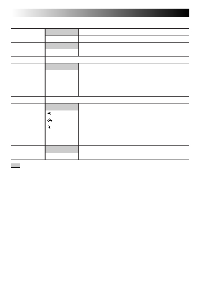
FOCUS Adjusts focus automatically.
EXPOSURE Adjusts exposure automatically.
DATE/TIME Allows you to set the current date and time (Z pg. 11).
TELE MACRO Usually the distance to a subject where the lens is in focus
TAPE LENGTH Allows you to set the tape length depending on the tape used (Z pg. 12).
M.W.B. This camcorder’s Automatic Color Temperature system senses
ZOOM SPEED Allows you to set the zooming speed (Z pg. 18).
= Factory setting and when the Select Dial is set to AUTO LOCK
AUTO
MANU
AUTO
MANU
OFF
ON
AUTO
: FINE
: CLOUD
: HALOGEN
MWB
FAST
SLOW
Allows you to adjust focus manually (Z pg. 30, 31).
Allows you to adjust exposure manually (Z pg. 32).
depends on the zoom magnification. Unless there is a distance
more than 1m (3.3 ft.) to the subject, the lens is out of focus at
the maximum telephoto setting. When set to “ON”, you can
shoot a subject as large as possible at a distance of approx.
60 cm (2 ft.).
•
Depending on the zoom position, the lens may go out of focus.
the color temperature of the ambient lighting for automatic
white balance adjustment. However, precise color adjustment is
not possible under the following conditions:
•When an object is in various shades of the same color.
•When a predominantly red or brown object is being shot
outdoors.
In these cases, use the camcorder’s built-in preset filters for
white balance adjustment (
Z pg. 33).
Page 29
EN 29
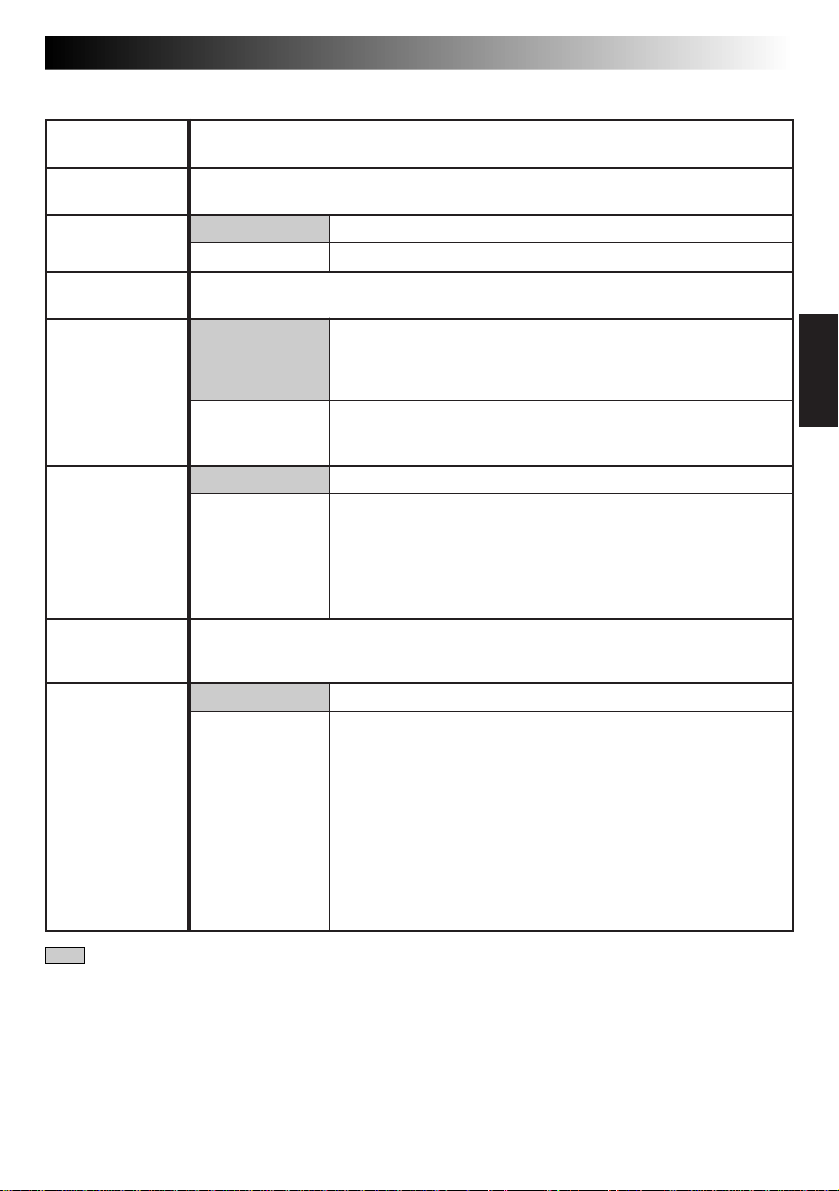
REC TIME This feature allows you to set the parameters for Animation and Time-Lapse
INT. TIME This feature allows you to set the parameters for Self-Timer (Z pg. 34) and Time-
TALLY LAMP ON The tally lamp comes on to signal the start of recording.
TITLE LANG. Allows you to select the language (ENGLISH, FRENCH, SPANISH or PORTUGUESE)
D. ZOOM ON Allows you to use the Digital Zoom. By digitally processing and
COLOR BAR OFF Does not display color bars. Normal screen is recorded.
JLIP ID NO. This number is necessary when connecting the camcorder to a device such as a
DEMO MODE OFF Automatic demonstration will not take place.
recording (Z pg. 35).
Lapse recording (Z pg. 35).
OFF The tally lamp remains off at all times.
of Instant Titles (Z pg. 25).
magnifying images, zooming is possible from 22 times (the
optical zoom limit), to a maximum of 44 times digital magnification.
OFF Digital Zoom is not available. Only optical zoom (maximum
22x magnification) can function. When set to “OFF” during
Digital Zoom, zoom magnification changes to 22x.
ON Makes the normal screen disappear, then displays color bars. By
recording color bars at the beginning or end of a tape, an effect
similar to professional productions can be given to your tape.
NOTE:
While the color bars are displayed, the camcorder’s other
functions are disabled.
computer using the J terminal (JLIP). The numbers range from 01 to 99. Factory
setting is 07.
ON Demonstrates certain functions such as the Fader, Instant Titles
etc. When “DEMO MODE” is set to “ON” and the Menu Screen
is closed, demonstration starts.
NOTES:
● When a tape whose Erase Protection tab is in the position that
allows recording is loaded in the camcorder, demonstration is
not available.
● By turning off the camcorder or inserting a tape whose Erase
Protection tab is in the position that allows recording into it,
“DEMO MODE” is set to “OFF” automatically.
● During demonstration, all functions except zoom are disabled.
= Factory setting and when the Select Dial is set to AUTO LOCK
Page 30

30 EN
Focus detection zone
RECORDING
Advanced Features (cont.)
Focusing
Auto Focus
The camcorder’s Full Range AF system offers continuous
shooting ability from close-up to infinity. However,
correct focus may not be obtainable in the situations
listed below (in these cases use manual focusing):
•When two subjects overlap in the same scene.
•When illumination is low.*
•When the subject has no contrast (difference in
brightness and darkness), such as a flat, one-color wall,
or a clear, blue sky.*
•When a dark object is barely visible.*
•When the scene contains minute patterns or identical
patterns that are regularly repeated.
•When the scene is affected by sunbeams or light
reflecting off the surface of a body of water.
•When shooting a scene with a high-contrast
background.
* The low-contrast warning “
NOTES:
●
If the lens is smeared or blurred, accurate focusing is
not possible. Keep the lens clean, wiping with a piece
of soft cloth if it gets dirty. When condensation occurs,
wipe with a soft cloth or wait for it to dry naturally.
●
When shooting a subject close to the lens, zoom-out
first (Z pg. 18). If zoomed-in in the auto focus mode,
the camcorder could automatically zoom out depending on the distance between the camcorder and the
subject. When Tele Macro (Z pg. 28) is activated, the
camcorder will not zoom out automatically.
” appears.
Page 31
Select Dial
Viewfinder
MENU
4
MENU END
FOCUS
EXPOSURE
DATE TIME
TELE MACRO
TAPE LENGTH
M. W. B.
ZOOM SPEED
4
NEXT
Menu Screen
AUTO
AUTO
DEC
OFF
T30
AUTO
FAST
25.98
MENU Jog Dial
No indication
during
recording
EN 31
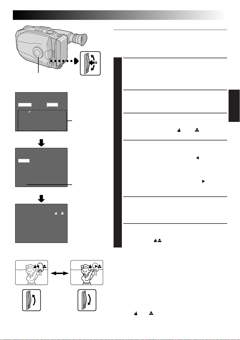
Manual Focus
NOTE:
You should already have made the necessary viewfinder
adjustments (Z pg. 14). If you haven’t, do so before
continuing.
ACCESS MENU SCREEN
Turn the Select Dial to any position except AUTO
1
LOCK, then press the MENU Jog Dial. The Menu
Screen appears, and the highlight bar is placed on
“FOCUS”.
ACCESS FOCUS MENU SCREEN
Press the MENU Jog Dial.
2
ACCESS MANUAL FOCUS
Rotate the MENU Jog Dial to move the highlight bar
3
to “MANU”, then press it. “
focus is locked at this point.
” and “ ” appear. The
FOCUS
AUTO
MANU
EXIT
Focus Menu Screen
Manual Focus Screen
No indication
during
recording
ADJUST FOCUS
To farther subject . . .
4
Rotate the MENU Jog Dial upward. “ ” appears and
blinks.
Go to step 5.
To nearer subject
Rotate the MENU Jog Dial downward. “ ” appears
and blinks.
Go to step 5.
. . .
END ADJUSTMENT OF FOCUS
Press the MENU Jog Dial. The Menu Screen
5
reappears and the highlight bar is placed on “MENU
END”.
CLOSE MENU
Press the MENU Jog Dial. The Menu Screen
6
disppears and “ ” reappears to indicate the focus
is locked.
NOTES:
●
To return to Auto Focus, select “AUTO” in step 3.
●
To re-adjust Manual Focus, repeat the procedure from
step 1.
●
Be sure to focus the lens in the maximum telephoto
position when you use the Manual Focus mode. If you
focus in on a certain subject in the wide-angle position,
sharply focused images cannot be obtained when
zoomed up because the depth-of-field is reduced at
longer focal lengths.
●
When the focus level cannot be adjusted any farther or
closer, “ ” or “ ” will blink.
Page 32
32 EN
Select Dial
Viewfinder
MENU
4
MENU END
FOCUS
EXPOSURE
DATE TIME
TELE MACRO
TAPE LENGTH
M. W. B.
ZOOM SPEED
4
NEXT
Menu Screen
EXPOSURE
AUTO
MANU
EXIT
Exposure Menu Screen
AUTO
AUTO
DEC
OFF
T30
AUTO
FAST
25.98
00
MENU Jog Dial
No indication
during
recording
No indication
during
recording
Exposure
control
level
counter
RECORDING
Advanced Features (cont.)
Exposure Control
This feature automatically adjusts the iris for the best
available picture quality, but you can override and make
the adjustment manually.
ACCESS MENU SCREEN
Turn the Select Dial to any position except AUTO
1
LOCK, then press the MENU Jog Dial. The Menu
Screen appears.
ACCESS EXPOSURE MENU
SCREEN
Rotate the MENU Jog Dial to move the highlight bar
2
to “EXPOSURE” and press it.
ACCESS MANUAL EXPOSURE
Rotate the MENU Jog Dial to move the highlight bar
3
to “MANU”, then press it. “00” (exposure control
level counter) appears.
ADJUST EXPOSURE
To brighten the image . . .
4
Rotate the MENU Jog Dial upward. The exposure
control level counter increases (maximum +06).
Go to step 5.
To darken the image
Rotate the MENU Jog Dial downward. The exposure
control level counter decreases (maximum –06).
Go to step 5.
END ADJUSTMENT OF EXPOSURE
Press the MENU Jog Dial. The Menu Screen
5
reappears and the highlight bar is placed on “MENU
END”.
CLOSE MENU
Press the MENU Jog Dial. The Menu Screen
6
disappears and the exposure control level counter
reappers to indicate the exposure is adjusted.
. . .
Manual Exposure Screen
To brighten the image
–
06
+
06
To darken the image
NOTES:
●
To return to the factory setting, select “AUTO” in step 3.
●
To re-adjust exposure, repeat the procedure from step
1.
Page 33

Viewfinder
MENU
4
MENU END
FOCUS
EXPOSURE
DATE TIME
TELE MACRO
TAPE LENGTH
M. W. B.
ZOOM SPEED
4
NEXT
M. W. B.
AUTO
: FINE
: CLOUD
: HALOGEN
MWB
EXIT
AUTO
AUTO
DEC
OFF
T30
AUTO
FAST
25.98
Menu Screen
M.W.B.
Menu Screen
EN 33
Manual White Balance Adjustment
(M.W.B.)
The white balance is usually adjusted automatically.
However, the more advanced camcorder operator would
prefer to control this function manually and achieve a
more professional color/tint reproduction.
ACCESS MENU SCREEN
Turn the Select Dial to any position except AUTO
LOCK, then press the MENU Jog Dial. The Menu
1
Screen appears.
ACCESS WHITE BALANCE MENU
SCREEN
Rotate the MENU Jog Dial to move the highlight bar
to “M.W.B.”, then press it.
2
SELECT WHITE BALANCE
Rotate the MENU Jog Dial to move the highlight bar
to the required white balance.
3
“AUTO” ................... Automatic adjustment
“
: FINE” ............. Outdoors on sunny day
“
: CLOUD” ........ Outdoors on cloudy day
“
: HALOGEN” ... Light source is halogen or
“MWB” .................... When using a personal White
tungsten lamp
Balance Setting stored in
memory (see below.)
Select Dial
MENU
Jog Dial
NOTES:
●
To switch to automatic white balance
adjustment, set the M.W.B. in the Menu
Screen to “AUTO”, or turn the Select Dial to
“AUTO LOCK”.
●
Re-adjust the White Balance when the
lighting has changed, when the camcorder
has been turned off and on again, or when
the Select Dial’s position has been changed.
●
When adjusted by putting colored paper in
front of the subject in step 1 of “MWB”, this
unit makes its color temperature standard for
automatic white balance. So you can enjoy
shooting with different colors. For example,
when adjusting with red, blue or yellow
colors, the image becomes the color which
approximates to green, orange or purple
respectively.
●
It is helpful to connect your camcorder to a
color monitor when adjusting the white
balance (Z pg. 37).
CLOSE MENU
Press the MENU Jog Dial. The Menu Screen
reappears. Then press the MENU Jog Dial again to
4
exit the Menu Screen.
MWB
MWB sets the color temperature for the subject’s light
source so you can shoot with natural colors that are
unaffected by surroundings, even when there are
multiple subjects with different color temperatures.
PREPARE WHITE OBJECT
Point the camcorder at a white, flat object such as a
1
sheet of white paper.
SELECT MWB
Follow step 1 through 3 of the above, select
“MWB”.
2
MEMORIZE WHITE BALANCE
Press the MENU Jog Dial until “MWB” begins
blinking. “MWB” blinks while the white balance is
3
being stored in memory, then the Menu Screen
reappears when memorization is complete.
CLOSE MENU
Press the MENU Jog Dial.
4
Page 34

34 EN
Recording
Start/Stop Button
Select Dial
Viewfinder
4
MENU END
FOCUS
EXPOSURE
DATE TIME
TELE MACRO
TAPE LENGTH
M. W. B.
ZOOM SPEED
4
NEXT
4
BACK
REC TIME
INT. TIME
TALLY LAMP
TITLE LANG.
D. ZOOM
COLOR BAR
JLIP ID NO.
DEMO MODE
4
MENU END
OFF
15 S
30 S
1 MIN
5 MIN
MENU
MENU
INT. TIME
AUTO
AUTO
DEC
25.98
OFF
T30
AUTO
FAST
OFF
OFF
ON
ENGLISH
ON
OFF
07
OFF
MENU Jog Dial
Menu Screen
REC TIME
OFF
1 4 S
1 2 S
1 S
5 S
RECORDING
Advanced Features (cont.)
Self-Timer
You can set the delay between pressing the Recording
Start/Stop Button and the actual start of recording. If you
secure the camcorder, you (or whomever is operating the
camcorder) can enter the scene before recording starts.
NOTE:
Make sure the camcorder is in the Record-Standby mode
before performing the following steps.
ACCESS MENU SCREEN
Turn the Select Dial to any position except AUTO
1
LOCK, then press the MENU Jog Dial.
ACCESS INT. TIME MENU SCREEN
Rotate the MENU Jog Dial to move the highlight bar
2
to “INT. TIME”, then press the MENU Jog Dial.
SET INTERVAL TIME
Rotate the MENU Jog Dial to move the highlight bar
3
to the desired time, then press the MENU Jog Dial.
The Menu Screen reappears and the highlight bar is
placed on “MENU END”.
CLOSE MENU
Press the MENU Jog Dial.
4
START DELAYED RECORDING
Press the Recording Start/Stop Button. When the
5
selected time has elapsed, recording begins
automatically.
To Cancel Self-Timer . . .
... Before the recording begins, press the Recording Start/
Stop Button to display “
TIME” in the Menu Screen to “OFF”.
PAUSE
”, then set “INT.
EXIT
INT. TIME Indicator
15S
1S
REC TIME Indicator
EXIT
REC TIME MenuINT. TIME Menu
INT. TIME and
REC TIME
indications on the
normal screen
Page 35

Animation
Give stationary scenes or objects an illusion of
movement. This function allows you to shoot a
series of pictures, each slightly different, of the same
object for a brief period of time.
NOTE:
Make sure the camcorder is in the Record-Standby
mode and the recording mode is set to “SP” before
performing the following steps.
EN 35
Time-Lapse
You can record sequentially at preset time spans.
Leaving the camcorder aimed at a specific subject,
you can record subtle changes over an extended
period of time.
NOTE:
Make sure the camcorder is in the Record-Standby
mode and the recording mode is set to “SP” before
performing the following steps.
ACCESS MENU SCREEN
Turn the Select Dial to any position except
1
AUTO LOCK, then press MENU Jog Dial.
SET RECORDING TIME
Rotate the MENU Jog Dial to move the
2
highlight bar to “REC TIME”, then press the
MENU Jog Dial. The REC TIME Menu appears.
Rotate the MENU Jog Dial to move the
highlight bar to the desired time, then press the
MENU Jog Dial. The Menu Screen reappears.
Press the MENU Jog Dial again to exit the
Menu Screen.
START RECORDING
Press the Recording Start/Stop Button after
3
focusing on the subject. The recording stops
automatically after the selected period of time.
ASSEMBLE SERIES OF
PICTURES
Repeat step 3 for the desired number of
4
pictures.
RELEASE ANIMATION MODE
Set “REC TIME” in the Menu screen to “OFF”.
5
NOTES:
●
For best results, make sure the camcorder is
secured when shooting in Animation or TimeLapse mode.
●
Fade or Wipe-in/out cannot be performed during
Animation or Time-Lapse shooting.
●
Before performing other operations following
Animation or Time-Lapse recording, make sure
the Animation or Time-Lapse mode is deactivated.
●
Self-Timer, Animation and Time-Lapse are
canceled when the power is shut off or when the
cassette is ejected.
ACCESS MENU SCREEN
Turn the Select Dial to any position except
1
AUTO LOCK, then press MENU Jog Dial.
SET INTERVAL BETWEEN
RECORDINGS
Rotate the MENU Jog Dial to move the
2
highlight bar to “INT. TIME”, then press the
MENU Jog Dial. The INT. TIME Menu appears.
Rotate the MENU Jog Dial to move the
highlight bar to the desired time, then press the
MENU Jog Dial. The Menu Screen reappears.
SET RECORDING TIME
Rotate the MENU Jog Dial to move the
3
highlight bar to “REC TIME”, then press the
MENU Jog Dial. The REC TIME Menu appears.
Rotate the MENU Jog Dial to move the
highlight bar to the desired time, then press the
MENU Jog Dial. The Menu Screen reappears.
Press the MENU Jog Dial again to exit the
Menu Screen.
START TIME-LAPSE
RECORDING
Press the Recording Start/Stop Button.
4
Recording and intervals alternate
automatically.
RELEASE TIME-LAPSE MODE
To release when “
5
“REC TIME” and “INT. TIME” in the Menu
Screen to “OFF”. To release when
“
PAUSE
press the Recording Start/Stop Button to display
“
PAUSE
TIME” in the Menu Screen to “OFF”.
PAUSE
REC
” and “
”, then set “REC TIME” and “INT.
” is displayed, set
” are not displayed,
Page 36

36 EN
Compact video cassette
VCR
Compartment door
Sliding latch
PLAYBACK
Using The Cassette Adapter
Cassette Adapter (VHS Playpak)
Use this to play back a VHS-C video cassette recorded
with this camcorder. It is fully compatible with any VHS
video cassette recorder. The C-P7U adapter is battery
powered and automatically performs tape loading and
unloading.
INSERT BATTERY
Slide the battery cover up to remove it, and install
1
one “AA(R6)” size battery as shown in the illustration at left. Then reattach the cover.
INSERT CASSETTE IN ADAPTER
Slide the latch to open the adapter compartment
2
door, then insert the cassette and close the compartment door.
PLAY BACK ON CONNECTED VCR
Load the cassette adapter into the VCR and play the
3
tape back as you would any other.
REMOVE CASSETTE FROM
ADAPTER
Slide the latch and the compartment door opens
4
automatically. This may take around 10 seconds. Do
not attempt to force the adapter open. Then insert
your finger in the hole on the underside of the
adapter as shown in the illustration at left, push up
and remove the cassette.
Recording safety hole
Reels
NOTES:
●
During tape loading and unloading, do not touch the
reels for safety and tape protection.
●
During special-effect playback (slow motion, still
frame, etc.), the picture may vibrate or noise bars may
appear on the screen.
●
To record on a VCR using a compact cassette and the
adapter, cover the adapter’s recording safety hole with
adhesive tape.
Page 37

PLAYBACK
When
connecting
the cables,
open the
jack cover.
Basic Connections
To AUDIO and VIDEO
OUT connectors
Audio and Video
cables (optional)
EN 37
There are three basic types of connections. When making
the connections, refer also to your VCR and TV
instruction manuals.
Connection To A VCR A (Editing, Dubbing
and Playback)
NOTE:
Use the optional Audio and Video cables.
CONNECT CAMCORDER TO VCR
As shown in the illustration at left, connect the
1
Audio and Video cables between the AUDIO and
VIDEO OUT connectors on the camcorder and
those on the VCR.
To AUDIO and
VIDEO IN
connectors
VCR
Antenna
To AUDIO, VIDEO
and RF DC OUT
connectors
RF unit RF-V5U
(optional)
NOTES:
●
It is recommended to use the AC Power
Adapter/Charger as the power supply instead
of the battery pack.
●
To monitor the picture and sound from the
camcorder without inserting a tape, set the
camcorder’s Power Switch to “CAMERA”,
then set your TV to the appropriate input
mode.
●
If you have a TV or speakers that are not
specially shielded, do not place the speakers
adjacent to the TV as interference will occur
in the camcorder playback picture.
SUPPLY POWER
Turn on the camcorder, the VCR and the TV.
2
SELECT MODE
Set the VCR to its AUX input mode, and set the TV
3
to its VIDEO mode.
Connection To A TV With A/V Input
B
Connectors
NOTE:
Use the optional Audio and Video cables.
CONNECT CAMCORDER TO TV
As shown in the illustration at left, connect the
1
Audio and Video cables between the AUDIO and
VIDEO OUT connectors on the camcorder and
those on the TV.
SELECT MODE
Set the TV to its VIDEO or AV mode (as specified in
2
its instructions).
Connection To A TV With NO A/V Input
Connectors (Playback ONLY)
NOTE:
Use the optional RF-V5U RF unit.
* Refer to the RF-V5U instruction manual for connection
procedure.
(Playback ONLY)
Page 38

38 EN
REW
PLAY/PAUSE
PLAYBACK
Basic Playback
LOAD A CASSETTE
Slide EJECT to open the cassette holder, then insert
1
the cassette with the label facing out. Press PUSH to
ensure the holder is closed and locked.
FF
SELECT MODE
Set the Power Switch to “PLAY”. The power
2
indicator lights.
STOP
Power Switch
Recording mode indicator
Tape running
SP
4
M–0:23:45
Tape counter
indicator
4
: Playback
3
: Fast-Forward/
2
: Rewind/Reverse
6 : Still Playback
PLAY BACK
Press PLAY/PAUSE. The playback picture appears.
3
STOP PLAYBACK
Press STOP.
4
Rewind or Fast-forward the tape
Press REW to rewind, or FF to fast-forward the tape
during Stop mode.
NOTE:
The camcorder shuts off automatically after about 5
minutes in Stop mode. To turn on again, set the Power
Switch to “POWER OFF”, then to “PLAY”.
Forward Search
Search
Page 39

PLAYBACK
Features
MENU Jog Dial
Tracking
AT
This function can be used to eliminate noise bars that
appear on-screen during playback. Initial setting is Auto
Tracking. Manual Tracking is also available.
ACTIVATE MANUAL TRACKING
Press the MENU Jog Dial during playback mode.
1
Keep rotating it until noise bars disappear.
•To return to Auto Tracking, press the MENU Jog
Dial. “AT” blinks. When Auto Tracking finishes,
the indication disappears.
NOTES:
●
When noise bars appear during playback, the
camcorder enters the Auto Tracking mode and “AT” is
displayed.
●
Manual Tracking may not work with tapes recorded on
other VCRs or camcorders.
EN 39
Page 40

40 EN
STOP
COUNTER R/M
PLAY/PAUSE
FFREW
PLAYBACK
FEATURE: Still Playback
PURPOSE: To pause during playback.
OPERATION: 1) Press PLAY/PAUSE during
NOTE:
FEATURE: Shuttle Search
PURPOSE: To allow high-speed search in either
OPERATION:
NOTE:
FEATURE: Counter Memory Function
PURPOSE: To make it easier to locate a specific
OPERATION: 1) Press COUNTER R/M and hold for
NOTES: ●
playback.
2) To resume normal playback, press
PLAY/PAUSE again.
Noise bars appear and pictures may
become monochrome during Still
Playback. This is normal.
direction.
Forward Search
1) Press FF during playback.
Reverse Search
1) Press REW during playback.
Noise bars appear and pictures may
become monochrome or darken in
Shuttle Search. This is normal.
tape segment.
more than 1 second. The counter
resets to “0:00:00”.
2) Press COUNTER R/M for less than
1 second. “M” appears.
3) After recording or playback, press
STOP, then REW. The tape
automatically stops at or close to
0:00:00.
4) Press PLAY/PAUSE to start
playback.
The counter memory functions in
the Fast-Forward and Rewind
modes.
●
To disable Counter Memory
Function, press COUNTER R/M for
less than 1 second so the “M”
disappears.
Features (cont.)
Page 41

TAPE DUBBING
PLAY/PAUSE
Power Switch
When connecting
the cables, open
the jack cover.
Audio and Video
cables (optional)
To AUDIO and
VIDEO OUT
connectors
To AUDIO and
VIDEO IN
connectors
Tape Dubbing
CONNECT EQUIPMENT
Following the illustration at left, connect the
1
camcorder and the VCR.
PREPARE FOR DUBBING
Set the camcorder’s Power Switch to “PLAY”, turn
2
on the VCR’s power, and insert the appropriate
cassettes in the camcorder and the VCR.
SELECT VCR MODE
Engage the VCR’s AUX and Record-Pause modes.
3
FIND EDIT-IN POINT
Engage the camcorder’s Play mode to find a spot
4
just before the edit-in point. Once it’s reached, press
PAUSE on the camcorder.
START EDITING
Press PLAY on the camcorder and engage the VCR’s
5
Record mode.
STOP EDITING TEMPORARILY
Engage the VCR’s Record-Pause mode and press
6
PAUSE on the camcorder.
EDIT MORE SEGMENTS
Repeat steps 4 through 6 for additional editing, then
7
stop the VCR and camcorder when finished.
EN 41
VCR (Recording deck)
Page 42

42 EN
2
1
3
4
5
6
1
7
%
^
2
@
4
6
&
The Full-Function Remote Control Unit can operate this camcorder from a distance as well as the basic
operations (PLAY, STOP, PAUSE, FF, and REW) of your VCR. This remote control unit makes additional
recording functions possible.
USING REMOTE CONTROL UNIT
A
a
2
1
RM-V705U
(provided)
BUTTONS
1 Infrared beam
transmitting window
2 ZOOM (T/W) Buttons Zoom in/out (Z pg. 18) —
3 PLAY Button — Playback start (Z pg. 38)
4 STOP Button — Stop (Z pg. 38)
5 REW Button Retake (rewind)/Quick Review (Z pg. 19) Rew/Rew Shuttle Search (Z pg. 38, 40)
6 INSERT Button — Insert Editing (Z pg. 48)
7 START/STOP Button Functions same as the Recording Start/Stop button on the camcorder.
8 INT. TIME Button Self-Timer/Time-Lapse (Z pg. 43) —
9 REC TIME Button Animation/Time-Lapse (Z pg. 43) —
0 PAUSE Button — Pause (Z pg. 40)
! FF Button Retake (forward) (Z pg. 19) FF/FF Shuttle Search (Z pg. 38, 40)
@ A.DUB Button — Audio dubbing (Z pg. 49)
# PAUSE IN Connector — Z pg. 45
$ MBR SET Button — Z pg. 44
% VISS Button Index Code marking (Z pg. 43) —
^ VCR CTL Button — Z pg. 44
& R.A.EDIT Buttons — Z pg. 46
# — & : RM-V700U only.
B
2
3
3
1
Lock hole
#
7
8
$
9
8
9
0
!
5
!
0
3
@
With the camcorder’s power switch With the camcorder’s power switch
set to “CAMERA”. set to “PLAY”.
Transmits the beam signal.
1
1
C
2
1
RM-V700U
(optional)
3
1
Release
tab
INSTALLING THE BATTERY
PULL OUT BATTERY
HOLDER
TypeA: Pull out by inserting a pointed
1
TypeB: Pull out while sliding the lock
TypeC: Pinch the release tab and pull
instrument into slot a.
hole.
out.
INSERT BATTERY
Making sure the plus (+) side is up, insert
2
the lithium battery (CR2025)* into the
battery holder.
REPLACE BATTERY HOLDER
Insert the battery holder into the remote
3
control unit, and push the holder until it
clicks into place.
* Read the caution concerning lithium
batteries (
FUNCTIONS
Z pg. 2).
Page 43

Transmitted beam
effective area
15°
5m(16.4ft)
30°
15°
30°
Remote sensor
When using the remote control, be sure to
point it at the remote sensor. The above
illustration shows the approximate transmitted
beam effective area for indoor use.
The transmitted beam may not be effective or
may cause incorrect operation outdoors or
when the remote sensor is directly exposed to
sunlight or powerful lighting.
Interval Timer Indicator
Viewfinder
1 2S
INDEX1MIN
Index Code
Marking
Rec Time Indicator
START/STOP
VISS
INT. TIME
REC TIME
RM-V700U
(optional)
OR
RM-V705U
(provided)
EN 43
FEATURE: Self-Timer, Animation and Time-Lapse
PURPOSE: The remote control lets you set/release
OPERATION:
NOTE:
FEATURE: Index Code Marking (RM-V700U only)
PURPOSE: To give you automatic access to any
OPERATION: 1) Press VISS once to place the index
NOTE:
Interval Timer and Rec Time functions
as well as the Menu Screen.
Self-Timer
1) Set
Instead of performing steps 1 through
4 on pg. 34 (“Self-Timer”), press INT.
TIME on the remote control. Each
time INT. TIME is pressed, the
Interval Timer indicator appears,
changing in the following order: 15S,
30S, 1MIN, 5MIN and No indication
(off).
2) Release
Instead of setting “INT. TIME” to
“OFF” in the Menu, press INT. TIME
on the remote control until the
Interval Timer indicator disappears.
Animation
1) Set
Instead of performing steps 1 and 2
on pg. 35 (“Animation”), press REC
TIME on the remote control. Each
time REC TIME is pressed, the Rec
Time indicator appears, changing in
the following order: 1/4S, 1/2S, 1S,
5S and No indication (off).
2) Release
Instead of using the Menu in step 5
on pg. 35, press REC TIME on the
remote control until the Rec Time
indicator disappears.
Time-Lapse
1) Set
Instead of performing steps 1 through
3 on pg. 35 (“Time-Lapse”), press
INT. TIME and REC TIME on the
remote control. Each time INT. TIME
is pressed, the Interval Timer
indicator appears, changing in the
following order: 15S, 30S, 1MIN,
5MIN and No indication (off). Each
time REC TIME is pressed, the Rec
Time indicator appears, changing in
the following order: 1/4S, 1/2S, 1S,
5S and No indication (off).
2) Release
Instead of using the Menu in step 5
on pg. 35, press INT. TIME and REC
TIME on the remote control until the
indicators disappear.
Also refer to pgs. 34 and 35.
selected point on a recording.
code. “INDEX” blinks during
marking.
If VISS is pressed during RecordStandby mode, the mark is placed
where START/STOP is pressed.
Page 44
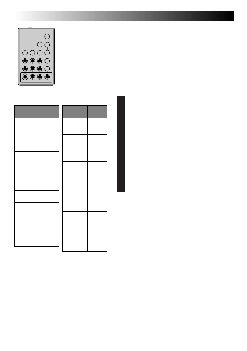
44 EN
1
4
7
2 3
5 6
8
USING REMOTE CONTROL UNIT
(cont.)
Random Assemble Editing [R.A.Edit]
Create edited videos easily using your camcorder as the
source player. You can select up to 8 “cuts” for automatic
MBR SET
VCR CTL
0
9
RM-V700U
(optional)
editing, in any order you like. R.A.Edit is more easily
performed when the optional RM-V700U MBR (MultiBrand Remote, Z pg. 42) is set to operate with your
brand of VCR (see VCR CODE LIST), but can also be
performed by operating the VCR manually.
Before operation, make sure the lithium battery is
installed in the remote control RM-V700U (Z pg. 42).
SET REMOTE/VCR CODE
VCR CODE LIST
VCR BRAND
NAME
GE
HITACHI
JVC
MAGNAVOX
MITSUBISHI
NEC
PHILIPS
BUTTONS
(A) (B)
1 1
9 2
9 `
9 4
6 6
6 3
9 1
A
9 6
B
9 3
C
9 5
1 1
7 1
7 6
6 7
6 8
3 7
3 8
1 9
9 5
1 1
9 4
9 1
9 6
VCR BRAND
NAME
PHILIPS
PANASONIC
RCA
SANYO
SHARP
SONY
TOSHIBA
ZENITH
BUTTONS
(A) (B)
1 2
3 3
7 2
1 3
1 7
1 1
9 4
1 8
9 2
9 4
6 6
6 3
9 `
3 6
3 5
1 5
1 `
6 5
6 `
3 9
3 1
6 9
6 1
1 6
SET REMOTE TO OPERATE VCR
Turn off the power to the VCR and point the remote
1
toward the VCR’s infrared sensor. Then, referring to
the VCR CODE LIST on the left, press and hold MBR
SET, and press button (A) and then (B).
•The code is automatically set once you release the
MBR SET button, and the VCR’s power comes on.
OPERATE VCR
Make sure the VCR’s power is on. Then, while
2
holding VCR CTL, press the button on the remote for
the desired function. The functions the remote can
control are PLAY, STOP, PAUSE, FF, REW and VCR
REC STBY (you don’t need to press VCR CTL for this
one).
You’re now ready to try Random Assemble Editing.
IMPORTANT
Although the MBR is compatible with JVC VCRs and
those of many other makers, it may not work with yours
or may offer limited functions.
NOTES:
●
If the VCR’s power doesn’t come on in step 1, try
another code from the VCR CODE LIST.
●
Some brands of VCR don’t come on automatically. In
this case, turn the power on manually and try step 2.
●
If the RM-V700U is not able to control the VCR, use
the controls on the VCR.
Page 45

Open the cover
To J terminal
(JLIP)
Editing cable
(optional, ø3.5
mini-plug cable)
C
To Pause-In
A
To Remote
PAUSE
To AUDIO and
VIDEO OUT
connectors
Audio and
Video cables
(optional)
B
To AUDIO
and VIDEO IN
connectors
VCR
(Recording deck)
MAKE CONNECTIONS
CONNECT TO . . .
A
JVC VCR EQUIPPED WITH REMOTE
1
PAUSE TERMINAL
Connect the editing cable to the Remote PAUSE
terminal.
B
JVC VCR NOT EQUIPPED WITH REMOTE
PAUSE TERMINAL BUT EQUIPPED WITH
R.A. EDIT CONNECTOR
Connect the editing cable to the R.A.EDIT
connector.
C
VCR OTHER THAN TYPE A OR
Connect the editing cable to the RM-V700U’s
Pause-In jack.
PREPARE CAMCORDER
Insert a recorded tape and set the Power Switch to
2
“PLAY”.
PREPARE VCR
Turn the power on, insert a recordable tape and
3
engage the AUX mode (refer to VCR’s instructions).
EN 45
B
RM-V700U
(optional)
Page 46

46 EN
REW
PLAY
IN/OUT
FFPLAY/PAUSE
REW
RM-V700U
(optional)
FF
PAUSE
ON/OFF
CANCEL
IN OUT
1 0:00:25 -- :-- : - 2
3
4
5
6
7
8
COUNTER 0:00:25
TOTAL 0:00:00
USING REMOTE CONTROL UNIT
SELECT SCENES
ACCESS R.A. EDIT COUNTER
STOP
DISPLAY
Press PLAY/PAUSE, then press ON/OFF and the
1
counter display appears in the viewfinder and the
screen of the connected TV.
REGISTER BEGINNING OF SCENE
Press REW or FF to locate the beginning of a scene
2
you want, then press IN/OUT to register that point.
The data appears under “IN” on the display.
REGISTER END OF SCENE
Press REW or FF to locate the end of the scene and
3
press IN/OUT to register it. The data appears under
“OUT” on the display. The total time of the
registered scene(s) is displayed at the bottom of the
screen.
REGISTER ADDITIONAL SCENES
Repeat steps 2 and 3 for each additional scene
4
(as many as 8).
MAKE CORRECTIONS
Press CANCEL during steps 2 and 3 to erase the
5
most recently registered point.
NOTES:
●
There must be at least one second between an in-point
and its corresponding out-point.
●
To ensure correct operation, there should be at least 15
seconds between an out-point and the next in-point.
●
Blank portions of tape cannot be registered as in-points
or out-points.
●
If it takes more than 5 minutes to search for an in-point,
the VCR’s Record-Pause mode is cancelled and editing
doesn’t take place.
●
Pressing ON/OFF clears all in- and out-points from
memory.
●
Leave a small margin for error around each in-point to
ensure the scene is recorded in its entirety.
(cont.)
IN OUT
1 0:00:25 0:01:05
2 0:03:18 0:03:31
3 0:02:33 0:02:53
4 0:04:11 --:- -: - 5
6
7
8
COUNTER 0:04:11
TOTAL 0:01:13
Page 47
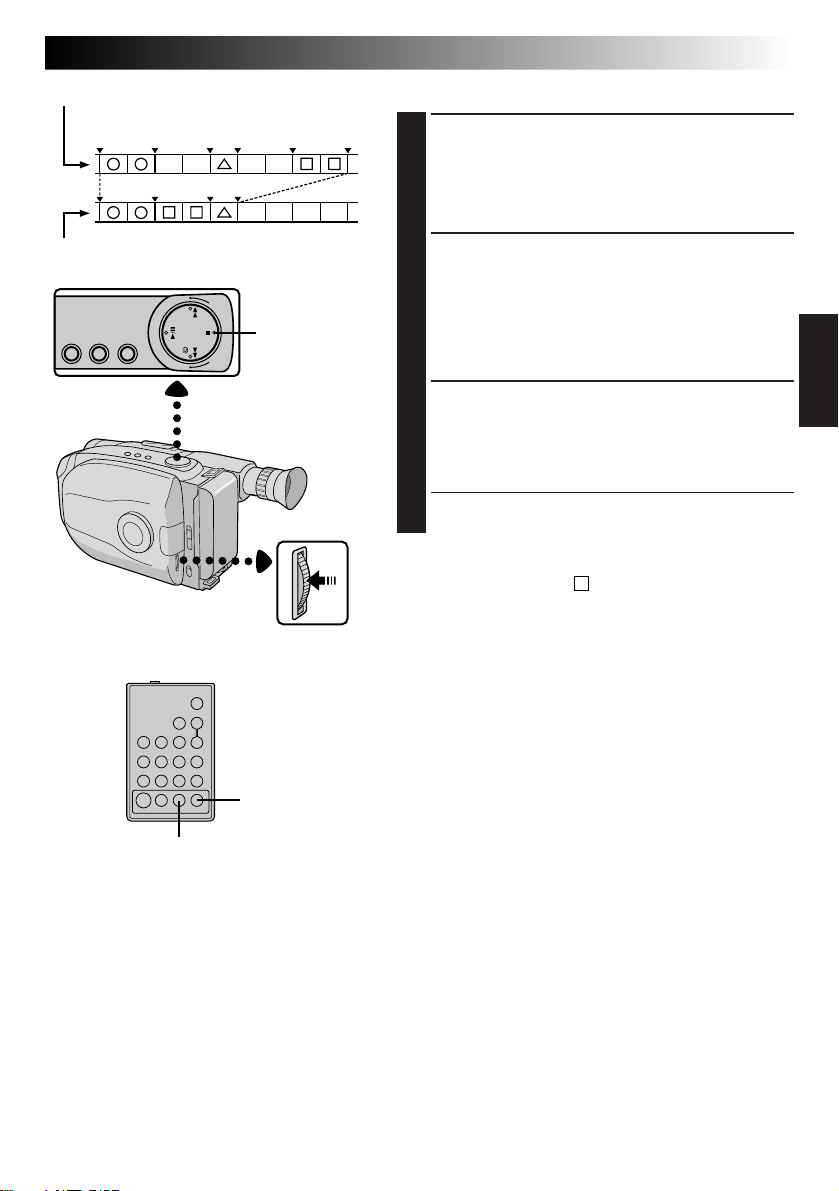
Original tape (camcorder)
1 3 2
IN OUT IN OUT IN OUT
AUTOMATIC EDITING TO VCR
ENGAGE VCR’S RECORD-PAUSE
MODE
Point the remote control toward the VCR’s infrared
1
sensor and press VCR REC STBY, or manually
engage the VCR’s Record-Pause mode.
EN 47
Edited tape (VCR)
STOP
MENU Jog Dial
RM-V700U
(optional)
ON/OFF
BEGIN AUTOMATIC EDITING
Press the MENU Jog Dial on the camcorder, and the
2
previously selected scenes are copied to the VCR in
the specified order.
While editing, the R.A. Edit counter of the scene
which is beging copied is shown with a blinking
highlight.
END AUTOMATIC EDITING
When all selected scenes have been copied, the
3
camcorder and VCR enter the still or pause mode.
Press STOP on both units. To make the R.A. Edit
counter display disappear, press ON/OFF.
•When finished editing, be sure to disconnect the
editing cable and the audio/video cable.
NOTES:
●
If you performed step 1C on page 45 (“MAKE
CONNECTIONS”), keep the remote control pointed at
the VCR during editing.
●
The on-screen display only appears while the
camcorder searches for each scene.
●
There may be noise at in- or out-points on the edited
tape with certain VCRs.
VCR REC STBY
Page 48

48 EN
COUNTER R/M
PLAY/PAUSE
REW FF
USING REMOTE CONTROL UNIT
Insert Editing
You can record a new scene into a previously recorded
tape, replacing a section of the original recording with
minimal picture distortion at the in- and out-points. The
original audio remains unchanged.
NOTE:
Use the RM-V705U or RM-V700U remote control unit to
perform this procedure.
(cont.)
M–0:12:34
Viewfinder
Power Switch
Insert editing
indicator
Tape Counter
STOP
SELECT MODE
Set the Power Switch to “PLAY”.
1
FIND EDIT-OUT POINT
Play back the tape, locate the point and press
2
PAUSE on the camcorder or the remote control.
RESET COUNTER
Press and hold COUNTER R/M for more than
3
1 second to reset the tape counter, then press again
for less than 1 second and make sure “M” appears.
FIND EDIT-IN POINT
Press REW to go a little beyond the beginning of the
4
scene you want to replace, press PLAY to view the
recorded tape, and press PAUSE exactly at the point
where the new scene should start.
ENGAGE INSERT EDITING MODE
Press and hold INSERT, and without releasing
5
INSERT, press and release PAUSE. The Insert mode
is engaged. When the scene the camcorder is aimed
at appears on the screen, go to the next step.
BEGIN INSERT EDITING
Press START/STOP. When the counter reaches
6
“0:00:00”, editing stops automatically and the
camcorder enters the Insert-Pause mode.
END INSERT EDITING
Press STOP.
7
RM-V700U
(optional)
START/STOP
REW
PLAY
PAUSE
REW
INSERT
OR
RM-V705U
(provided)
NOTES:
●
After step 5, Retake (Z pg. 19) can be performed.
●
The tape may stop slightly before or after the designated end point, and noise bars may appear. Neither
indicates a defect in the unit.
●
Only video signal is recorded in the Insert Editing
mode.
Page 49

Audio dubbing indicator
Viewfinder
Microphone
M–0:05:20
REW
EN 49
Audio Dubbing
e
4
You can record a new soundtrack on a prerecorded tape
(normal audio only).
Perform steps 1, 2 and 3 of the Insert Editing procedure
(Z pg. 48) before continuing.
•The sound comes from the built-in microphone.
FIND EDIT-IN POINT
Press REW to go a little beyond the beginning of the
1
scene onto which you want to dub new audio, press
PLAY to view the recorded tape, then press PAUSE
at exactly the point where dubbing should start.
ENGAGE AUDIO DUB-STANDBY
MODE
Press and hold A. DUB, and without releasing
2
A. DUB, press and release PAUSE.
BEGIN AUDIO DUBBING
Press PLAY. When the counter reaches “0:00:00”,
3
Audio Dubbing stops automatically and the
camcorder enters the Audio Dub-Standby mode.
END AUDIO DUBBING
Press STOP.
4
RM-V700U
(optional)
PLAY
PAUSE
REW
A. DUB
OR
RM-V705U
(provided)
NOTES:
●
Do not press FF or REW during Audio Dub-Standby, or
the edit points will not be accurate.
●
If the microphone is too close to the TV, or if the TV’s
volume is too high, whistling or howling may occur.
NOTES (for Insert Editing and
Audio Dubbing):
●
Insert Editing and audio Dubbing may not work
correctly if the tape contains blank segments, or if the
recording speed was changed during the original
recording.
●
To edit/dub onto a tape, make sure the Erase Protection
tab is in the position that allows recording. If not, slide
the tab. Some cassettes have removable tabs. If the tab
has been removed, cover the hole with adhesive tape.
●
Do not press STOP during Insert Editing or Audio
Dubbing, or the edit points will not be accurate.
●
During Insert Editing and Audio Dubbing, when InsertPause or Audio Dub-Standby is engaged, the counter
may go slightly past “0:00:00”. Recording, however,
stops at exactly 0:00:00.
Page 50

50 EN
BATT. RELEASE
LENS COVER
Open/Close Switch
Set to “POWER OFF”.
USER MAINTENANCE
After Use
Set the Power Switch to “POWER OFF” to turn off
1
the camcorder.
Slide EJECT to open the cassette holder, then remove
2
the cassette.
Close and lock the cassette holder by pressing
3
PUSH.
Slide BATT. RELEASE to remove the battery pack.
4
Slide the LENS COVER open/close switch to close
5
the lens cover.
PUSH
EJECT
Remove.
Marks
Cleaning The Camcorder
CLEAN EXTERIOR
Wipe gently with a soft cloth.
1
CLEAN LENS
Blow it with a blower brush, then wipe gently with
2
lens cleaning paper.
CLEAN VIEWFINDER
1 Turn the eyepiece counterclockwise and pull
3
it out.
2 Remove dust using a blower brush.
3 Align the marks, re-attach the eyepiece and turn
it clockwise.
NOTES:
●
Avoid using strong cleaning agents such as benzine or
alcohol.
●
Cleaning should be done only after the battery pack
has been removed or other power units have been
disconnected.
●
Mold may form if the lens is left dirty.
Page 51

TROUBLESHOOTING
EN 51
SYMPTOM
POWER
No power is supplied.
The power suddenly goes off and
doesn’t come back on by itself.
RECORDING
Recording cannot be performed.
Recording does not start.L
PLAYBACK
The tape is running, but there’s no
playback picture.
Playback picture is blurred or
interrupted.
The counter indication is blurred
during Still playback.
POSSIBLE CAUSE(S)
● The battery pack has not been attached correctly
(Z pg. 8).
● The battery pack is not charged (Z pg. 8).
● The power supply has not been correctly connected
(Z pg. 9).
● The battery pack has completely discharged.
● Remove the cassette and disconnect the power source,
then after a few minutes, try turning the power back on. If
it still doesn’t come on, consult your nearest JVC dealer.
● Make sure the Erase Protection tab is in the position that
allows recording. If not, slide the tab. Some cassettes have
removable tabs. If the tab has been removed, cover the
hole with adhesive tape.
● The camcorder Power switch has not been set to
“CAMERA” (Z pg. 16).
● The TV has not been set to its VIDEO mode or channel.
● If A/V connection is used, the TV’s VIDEO/TV switch has
not been set to VIDEO.
● The RF unit has not been set to the correct channel.
● The video heads are dirty or worn out. Consult your
nearest JVC dealer for head cleaning or replacement.
● This is normal.
TAPE TRANSPORT
The tape stops during fast-forward
or rewind.
Rewinding or fast-forwarding
cannot be performed.
● The Counter Memory Function has been activated
(Z pg. 40).
● The tape is already fully wound on one reel or the other.
Page 52

52 EN
TROUBLESHOOTING
(cont.)
SYMPTOM
OTHER
The tape won’t eject.
Some functions are not available.
Vertical white lines appear when
shooting a very bright object.
Bright, crystal-shaped spots appear
in the viewfinder.
The viewfinder and the lens have
become dirty (ex. fingerprints).
The picture is blurred in the Quick
Review or Retake mode.
An error number (i.e. E03) appears.
The image is out of focus.
The date and time displays
disappear.
The wrong date and time are
displayed/recorded.
Even though the Lens Cover is open,
the Lens Cover Warning indicator
blinks.
POSSIBLE CAUSE(S)
● The battery pack is running low.
● The Select Dial is set to “AUTO LOCK”.
● This sometimes occurs when the contrast between the
background and the object is great. It is not a defect of the
camcorder.
● Sunlight is directly entering the lens. This is not a defect of
the camcorder.
● Wipe them gently with soft cloth.
● This is normal while recording in the EP mode. Some
noise may be present while recording in the SP mode
(Z pg. 12).
● Turn the camcorder’s power off, then disconnect the
power source. After a few minutes, try turning the power
on again. If the error number still appears, consult your
nearest JVC dealer.
● The diopter needs to be adjusted (Z pg. 14).
● The scene being shot is adversely affecting the operation
of Auto Focus (Z pg. 30).
● If you remove the power source from the camcorder while
the power is on, all settings and selections are erased.
Make sure to turn the camcorder’s power off before
disconnecting the power source.
● If you have not performed Date/Time Setting (Z pg. 11),
the date and time are not displayed/recorded correctly. Be
sure that Date/Time setting is carried out.
● The Lens Cover Warning indicator may blink when the
camcorder is used in dark areas, regardless of the position
of the Lens Cover.
The camcorder is a microcomputer-controlled device. External noise and interference (from a TV, a radio,
etc.) might prevent it from functioning properly. In such cases, first disconnect its power supply unit
(battery pack, AC Power Adapter/Battery Charger, etc.) and clock battery; and then re-connect it and
proceed as usual from the beginning.
Page 53

INDEX
Indications
EN 53
8
1 6 7
30MIN
REC SP
444
3 4 5
2
S.LX T30
4
TWILIGHT
9
!
0
@
5MIN
1 4S
LENS COVER
PAUSE
TAPE END
#
$
%
Viewfinder Indications
1 Cassette Warning/
Tape Remaining Time ......................... Z pg. 17
When no cassette is inserted: the cassette (
warning blinks.
When Erase Protection tab is not in the position
that allows recording: the cassette ( ) warning
lights. Otherwise, the tape remaining time is
displayed and the tape remaining time warning
blinks when the tape is about to reach its end.
When the Power Switch is set to “PLAY” and a
tape is loaded: the cassette ( ) mark is displayed
regardless of the Erase Protection tab’s position.
2 Recording Mode (SP/EP) Indicator ....... Z pg. 12
3, 9 Program AE Indicator .....................Z pg. 22
Displayed at
Select Dial is switched from one position to
another. Then only the indicator remains at 9.
3, 0 Fade/Wipe-Standby Indicator......... Z pg. 24
Displayed at 3 for approx. 2 seconds when the
Fade/Wipe is switched from one function to
another by pressing the EFFECT button. Then
only the indicator remains at 0.
4 Multi-Function Control
Indication ................................... Z pg. 24 – 26
Displayed when any of the buttons located on
the Multi-Function Control is pressed. The
indication disappears within approx. 2 seconds.
5 Super LoLux Indicator .........................Z pg. 25
6 Tape Length Indicator ......................... Z pg. 12
7 Zoom Indicator Bar ............................. Z pg. 18
8 Recording Indicator ............................ Z pg. 16
! Picture Stabilizer Indicator ..................Z pg. 19
@ Interval Timer/
Recording Time Indicator.................... Z pg. 34
3 for approx. 1 second when the
MERRY CHRISTMAS
DEC 25.98 AM 11:45:18
)
^
&
NORM
01
MWB
*
(
)
q
# •Record-Standby Mode Indicator ....... Z pg. 16
•
Lens Cover Warning: LENS COVER
$ Instant Title Display ............................ Z pg. 26
% Date/Time Display ..............................Z pg. 20
^ Battery Pack Remaining Power Indicator
Changes as follows according to the battery
pack’s remaining power level:
“ ”. When the power is
almost gone, the indicator “ ” blinks (battery
power warning), then the unit shuts off. Replace
the battery pack with a fully charged one.
Note: The symbol containing 3 darkened
squares — — does not necessarily mean
that the battery pack is fully charged.
& Focus Indicator ................................... Z pg. 31
* Exposure Control Level Counter ......... Z pg. 32
( White Balance Mode Indicator ........... Z pg. 33
) Clock Battery Warning
Blinks for approx. 10 seconds when the power is
turned on. This display also blinks when the
clock (lithium) battery is either not installed or
has discharged. Install or replace the old battery
with a new one (
q •Tape End Display: TAPE END ...........Z pg. 17
Appears when the end of the tape is reached
during playback, recording or fast-forward.
•Condensation Warning:
When this indication appears, all functions
except tape eject and power on/off are disabled.
Turn the unit off (without removing the power
source) for a few hours, and when you turn it on
again the indication should disappear.
Z pg. 10).
... Z pg. 17
Page 54

54 EN
INDEX
(cont.)
y
u
i o
1
E
2
3
4
5
6
7
8
#
p
9
0
!
^
Q
)
%$@
W
q w e r
(
T
&R* t
Page 55

Controls
1 Power Zoom Button ........................... Z pg. 18
2 Select Dial ......................................... Z pg. 22
3 Multi-Function Control
•EFFECT Button ................................. Z pg. 24
•WIDE Button ...................................
•TITLE Button ....................................
•SUPER LOLUX Button .....................
4 PUSH Button ...................................... Z pg. 13
5 Recording Mode [SP/EP] Button ......... Z pg. 12
6 DATE/TIME Button ............................. Z pg. 20
COUNTER R/M Button .......................
7 P. [Picture] STABILIZER Button ........... Z pg. 19
8 REW Button ....................................... Z pg. 38
RETAKE R [Quick Review] Button ......
9 PLAY/PAUSE Button ........................... Z pg. 38
0 FF Button ........................................... Z pg. 38
RETAKE F Button ................................
! STOP Button ...................................... Z pg. 38
@ EJECT Switch ...................................... Z pg. 13
# Function Navigator Dial
[MENU Jog Dial] ................................ Z pg. 11
$ LIGHT OFF/AUTO/ON Switch ........... Z pg. 21
% BATT. [Battery] RELEASE Switch ......... Z pg. 8
^ Diopter Adjustment ............................ Z pg. 14
& Recording Start/Stop Button ................ Z pg. 16
* Power Switch ................................ Z pg.16, 38
( LENS COVER Switch .......................... Z pg. 16
Z pg. 25
Z pg. 26
Z pg. 25
Z pg. 40
Z pg. 19
Z pg. 19
EN 55
Connectors
) DC IN Jack ......................................... Z pg. 9
The jacks q to r are located beneath the jack
cover.
q J terminal
[JLIP (Joint Level Interface Protocol) Connector.]
•Connect the editing cable when performing
Random Assemble Editing (Z pg. 44 – 47).
•It is used to connect the camcorder to a device
such as a personal computer.
For further details consult your nearest JVC
dealer.
•JLIP-controlled editing from camcorder to VCR
is not possible if the VCR is not equipped with
a JLIP terminal.
w VIDEO OUT Connector ..................... Z pg. 37
e RF DC OUT Connector ...................... Z pg. 37
r AUDIO OUT Connector .................... Z pg. 37
Indicators
t Power Indicator .................................. Z pg. 16
y Tally Lamp ......................................... Z pg. 16
Other Parts
u Video Light ......................................... Z pg. 21
i Microphone ....................................... Z pg. 49
o • Camera sensor
Be careful not to cover this area; built-in
here is the sensor necessary for shooting.
•Remote Sensor ................................. Z pg. 43
p Clock Battery Compartment ............... Z pg. 10
Q Battery Pack Mount ............................ Z pg. 8
W Shoulder Strap Eyelets ........................ Z pg. 15
E Electronic Viewfinder ......................... Z pg. 14
R Grip Strap .......................................... Z pg. 14
T Tripod Mounting Socket ..................... Z pg. 15
Page 56

56 EN
A
AC Power Adapter .................................. pg. 8
Animation Recording .............................. pg. 35, 43
Audio Dubbing ....................................... pg. 49
Auto Date Record ................................... pg. 20
Auto Focus .............................................. pg. 30
Auto Mode Lock Mode ........................... pg. 23
Auto Mode Release Mode ....................... pg. 23
B
Battery Pack ............................................ pg. 8, 57
Brighten the Image .................................. pg. 32
C
Car Battery .............................................. pg. 9
Cassette Adapter ..................................... pg. 36
Charge Marker ........................................ pg. 9
Charging the Battery Pack ....................... pg. 8
Clock (Lithium) Battery ........................... pg. 10
Color Bar ................................................ pg. 29
Connection to a VCR/TV ......................... pg. 37
Contents ................................................. pg. 7
Counter Memory ..................................... pg. 40
D
Darken the Image ................................... pg. 32
Date/Time Insert...................................... pg. 20
Date/Time Setting.................................... pg. 11
DEMO Mode .......................................... pg. 29
Digital Zoom .......................................... pg. 18
Discharge the Battery pack...................... pg. 8
Diopter Adjust......................................... pg. 14
E
Electronic Fog Filter Mode ...................... pg. 23
Erase Protection ...................................... pg. 13
Exposure Control .................................... pg. 32
F
Fade-in/out ............................................. pg. 24
Fast-Forward Tape................................... pg. 38
G
Grip Adjustment...................................... pg. 14
H
High Speed Shutter Mode ....................... pg. 23
I
Index Code Marking ............................... pg. 43
Insert Cassette ......................................... pg. 13
Insert Editing ........................................... pg. 48
Instant Titles ............................................ pg. 26
M
Manual Focus ......................................... pg. 31
MBR Code Setting ................................... pg. 44
INDEX
Terms
N
ND Effect Mode ...................................... pg. 23
Nega/Posi Mode ..................................... pg. 23
P
Picture Stabilizer ..................................... pg. 19
Playback ................................................. pg. 38
Program AE with Special Effects .............. pg. 22, 23
Provided Accessories .............................. pg. 6
Q
Quick Review ......................................... pg. 19
R
Random Assemble Editing ....................... pg. 44–47
Recording, Advanced Features ................ pg. 22–35
Recording ............................................... pg. 16
Recording, Start/Stop............................... pg. 16, 17
Recording Mode Setting .......................... pg. 12
Record-Standby ...................................... pg. 16
Remote Control Unit ............................... pg. 42
Remove Cassette ..................................... pg. 13
Retake..................................................... pg. 19
Rewind Tape ........................................... pg. 38
S
Self-Timer ............................................... pg. 34, 43
Sepia Mode............................................. pg. 23
Shoulder Strap Attachment...................... pg. 15
Shuttle Search ......................................... pg. 40
Specifications.......................................... pg. 59
Sports Mode............................................ pg. 23
Still Playback .......................................... pg. 40
Super LoLux ............................................ pg. 25
T
Tape Counter .......................................... pg. 38
Tape Dubbing ......................................... pg. 41
Tape Length Setting ................................. pg. 12
Time-Lapse Shooting............................... pg. 35, 43
Tracking .................................................. pg. 39
Tripod Mounting ..................................... pg. 15
Twilight Mode ......................................... pg. 23
V
Video Light ............................................. pg. 21
Viewfinder Adjustment ............................ pg. 14
Viewfinder, indications............................ pg. 53
W
White Balance Adjustment...................... pg. 33
Wide Mode............................................. pg. 25
Wipe-in/out............................................. pg. 24
Z
Zooming ................................................. pg. 18
Page 57

CAUTIONS
EN 57
DANGER:
Video Light
•The video light becomes extremely hot. Do not
touch it either while in operation or soon after
turning it off, otherwise serious injury may result.
•Do not place the camcorder into the carrying case
immediately after using the video light, since it
remains extremely hot for some time.
•When operating, keep a distance of about 30 cm
(1 ft.) between the video light and people or
object.
•Do not use near flammable or explosive materials.
•It is recommended that you consult your nearest
JVC dealer for replacing the video light.
When using the AC Power Adapter/Charger in
areas other than the USA
n The provided AC Power Adapter/Charger features
automatic voltage selection in the AC range from
110 V to 240 V.
USING HOUSEHOLD AC PLUG ADAPTER
In case of connecting the unit’s power cord to an
AC wall outlet other than American National
Standard C73 series type use an AC plug adapter,
called a “Siemens Plug”, as shown.
For this AC plug adapter, consult your nearest JVC
dealer.
Plug adapter
General Battery Precautions
•When the C-P6U or C-P7U (cassette adapter) is
not functioning even when correctly operated, the
battery is exhausted. Replace it with a fresh one.
•Use only the following battery:
C-P6U or C-P7U..................... AA (R6) size
Please make note of the following rules for battery
use. When misused, battery can leak or explode.
1. Refer to the C-P6U/C-P7U instructions when
replacing the battery.
2. Do not expose the battery to excessive heat as it
can leak or explode.
3. Do not dispose of battery in a fire.
4. Remove battery from the unit if it is to be stored
for an extended period to avoid battery leakage
which can cause malfunctions.
Battery Packs
The supplied battery pack is a
nickel-cadmium battery. Before
using the supplied battery pack
or an optional battery pack, be
sure to read the following
cautions:
1. To avoid hazard . . .
.... do not burn.
.... do not short-circuit the terminals.
.... do not modify or disassemble.
.... use only specified chargers.
2. To prevent damage and prolong service life . . .
.... do not subject to unnecessary shock.
.... avoid repeated charging without fully
discharging.
.... charge in an environment where tempera-
tures are within the tolerances shown in the
chart below. This is a chemical reaction type
battery—cooler temperatures impede
chemical reaction, while warmer temperatures can prevent complete charging.
.... store in a cool, dry place. Extended exposure
to high temperatures will increase natural
discharge and shorten service life.
.... avoid prolonged uncharged storage.
.... remove from charger or powered unit when
not in use, as some machines use current
even when switched off.
NOTES:
●
It is normal for the battery pack to be warm after
charging, or after use.
Temperature Range Specifications
Charging.............. 10°C to 35°C (50°F to 95°F)
Operation ............ 0°C to 40°C (32°F to 104°F)
Storage ................ –10°C to 30°C (14°F to 86°F)
●
Recharging time is based on room temperature of
20°C.
●
The lower the temperature, the longer recharging
takes.
Terminals
Page 58

58 EN
Cassettes
To properly use and store your cassettes, be sure to
read the following cautions:
1. During use . . .
.... make sure the cassette bears the VHS-C
mark.
.... be aware that recording onto prerecorded
tapes automatically erases the previously
recorded video and audio signals.
.... make sure the cassette is positioned properly
when inserting.
.... do not load and unload the cassette
repeatedly without allowing the tape to run
at all. This slackens the tape and can result in
damage.
.... do not open the front tape cover. This
exposes the tape to fingerprints and dust.
2. Store cassettes . . .
.... away from heaters or other heat sources.
.... out of direct sunlight.
.... where they won’t be subject to unnecessary
shock or vibration.
.... where they won’t be exposed to strong
magnetic fields (such as those generated by
motors, transformers or magnets).
.... vertically, in their original cases.
Main Unit
1. For safety, DO NOT . . .
.... open the camcorder’s chassis.
.... disassemble or modify the unit.
.... short-circuit the terminals of the battery pack.
Keep it away from metallic objects when not
in use.
.... allow inflammables, water or metallic objects
to enter the unit.
.... remove the battery pack or disconnect the
power supply while the power is on.
.... leave the battery pack attached when the
camcorder is not in use.
2. Avoid using the unit . . .
.... in places subject to excessive humidity or
dust.
.... in places subject to soot or steam such as
near a cooking stove.
.... in places subject to excessive shock or
vibration.
.... near a television set.
.... near appliances generating strong magnetic
or electric fields (speakers, broadcasting
antennas, etc.).
.... in places subject to extremely high (over
40°C or 104°F) or extremely low (under 0°C
or 32°F) temperatures.
CAUTIONS
3. DO NOT leave the unit . . .
.... in places of over 50°C (122°F).
.... in places where humidity is extremely low.
(below 35%) or extremely high (above 80%).
.... in direct sunlight.
.... in a closed car in summer.
.... near a heater.
4. To protect the unit, DO NOT . . .
.... allow it to become wet.
.... drop the unit or strike it against hard objects.
.... subject it to shock or excessive vibration
during transportation.
.... keep the lens directed at extremely bright
objects for long periods.
.... direct the eyepiece of the viewfinder at the
sun.
.... carry it by holding the viewfinder. Be sure to
hold the main unit with both hands or use
the grip.
.... swing it excessively when using the shoulder
strap.
About moisture condensation . . .
● You may have observed that pouring a cold
liquid into a glass will cause drops of water to
form on the glass’ outer surface. This same
phenomenon occurs on the head drum of a
camcorder when it is moved from a cool
place to a warm place, after heating a cold
room, under extremely humid conditions or
in a place directly subjected to the cool air
from an air conditioner.
● Moisture on the head drum can cause severe
damage to the video tape, and can lead to
internal damage to the camcorder itself.
Serious malfunctioning
If malfunctioning occurs, stop using the unit
immediately and consult your local JVC dealer.
(cont.)
Page 59

SPECIFICATIONS
GENERAL
Format : VHS NTSC standard
Power source : DC 6V
Power consumption
light on : 8.0 W
light off : 5.1 W
Signal system : NTSC-type
Video recording system
Luminance : FM recording
Color : Converted sub-carrier
Cassette : cassette
Tape speed
SP :
EP :
Recording time (max.)
SP : 40 minutes
EP : 120 minutes
Operating temperature : 0°C to +40°C
Operating humidity : 35% to 80%
Storage temperature : –20°C to +50°C
Weight : Approx. 790 g (1.8 lbs)
Dimensions
(Including viewfinder) : 113 (W) x 117 (H) x
CAMERA
Pick up : 1/4” format CCD
Lens : F1.6, f = 3.8 to 83.6 mm,
Viewfinder :
White balance
adjustment : Auto/Manual adjustment
VIDEO
Output : 1 Vp-p, 75 ohms,
direct recording
Conforms to VHS
standard
33.35 mm/sec. (1-5/16 ips)
11.12 mm/sec. (7/16 ips)
(with TC-40 cassette)
(32°F to 104°F)
(–4°F to 122°F)
222 (D) mm (4-1/2” x
4-5/8” x 8-3/4”)
22:1 power zoom lens
with auto iris and macro
control, filter diameter
46 mm
Electronic viewfinder with
0.55” color LCD
unbalanced (via VIDEO
OUT connector)
EN 59
AC POWER ADAPTER/BATTERY CHARGER
(AA-V15U)
Power requirement : AC 110 V to 240 V`,
50/60 Hz
Power consumption : 23 W
Output
Charge : DC 8.5 V , 1.3 A
VTR : DC 6.3 V , 1.8 A
Charging system : Constant current,
peak detection,
timer controlled
Dimensions : 140 (W) x 42 (H) x
68 (D) mm (5-9/16” x
1-11/16” x 2-11/16”)
Weight : Approx. 300 g (0.71 lbs)
CASSETTE ADAPTER (C-P7U)
Dimensions : 188 (W) x 25 (H) x
104 (D) mm (7-7/16” x
1” x 4-1/8”)
Weight : Approx. 240 g (0.53 lbs)
Accessory : “AA (R6)”-size battery x 1
Provided Accessories ...................... Z pg. 6
Optional Accessories
•Battery Packs BN-V12U, BN-V22U, BN-V25U
•Car Battery Charger BH-V3U
•Battery Charger BH-VC10U
•Car Battery Cord AP-V7U
•RF Unit RF-V5U
•Compact VHS-C Cassettes TC-40/30/20
•Active Carrying Bag CB-V7U
•Remote Control Unit RM-V700U
Some accessories are not available in some areas.
Please consult your nearest JVC dealer for details on
accessories and their availability.
Specifications shown are for SP mode unless
otherwise indicated.
E. & O. E. Design and specifications subject to
change without notice.
AUDIO
Output : –8 dBs, 1 k-ohm
(via AUDIO OUT
connector)
Page 60

2 ES
Estimado cliente:
Le agradecemos la adquisición de la cámara de
video de VHS compacto de JVC. Antes de
utilizarla, lea la información y precauciones de
seguridad contenidas en las siguientes páginas
para utilizar su nueva cámara de video con
seguridad.
Uso de este manual de instrucciones
•Todas las secciones principales y subsecciones
están listadas en el índice (Z p. 7).
•Las notas aparecen al fin de la mayoría de las
subsecciones. No deje de leerlas.
•Las características/operación básicas y avanzadas
están separadas para facilitar la referencia.
Le recomendamos que . . .
.... se refiera al índice (Z p. 53 a 56) y que se
familiarice con la ubicación de los botones,
etc. antes de utilizar la cámara.
.... lea con atención las precauciones de
seguridad y las precauciones (Z p. 57 y 58)
siguientes. Las mismas contienen información
extremadamente importante referente al uso
seguro de su nueva cámara de video.
PRECAUCIONES
DE SEGURIDAD
ADVERTENCIA:
PARA EVITAR RIESGOS DE
INCENDIOS O
ELECTROCUCIONES, NO
EXPONGA ESTE APARATO A
LA LLUVIA O HUMEDAD.
Advertencia sobre la pila de litio
La pila utilizada en este aparato podría
ocasionar incendios o quemaduras por sus
productos químicos si no se la trata
adecuadamente. No la recargue, desarme,
caliente a más de 100°C o incinere.
Cámbiela por una CR2025 de Maxell,
Panasonic (Matsushita Electric), Sanyo o Sony;
el uso de otra pila podría acarrear riesgos de
incendio o explosión.
n Descarte inmediatamente las pilas usadas.
n Manténgala alejada del alcance de los niños.
n No la desarme ni la arroje al fuego.
Esta cámara de video está diseñada para ser
utilizada con señales de televisión en color
tipo NTSC. No puede emplearse para
reproducir en un televisor de otra norma. Sin
embargo, es posible grabar en vivo en
cualquier lugar. Utilice las baterías BN-V12U/
BN-V18U/BN-V22U/BN-V25U, re-cargándolas
con el adaptador/cargador de CA suministrado.
(Posiblemente sea necesario un adaptador de
conversión apropiado que se adecúe al tipo de
toma de corriente de su país.)
NOTAS:
●
La placa indicadora (placa del número de
serie) y la precaución de seguridad están en
la parte inferior y/o en la parte trasera de la
unidad principal.
●
La placa indicadora (placa del número de
serie) del adaptador/cargador de CA está en
la parte inferior del mismo.
Esta unidad ha sido fabricada de acuerdo con la
norma IEC Publ. 65.
PRECAUCIONES:
n Para evitar cortocircuitos, no abra la cámara
de video. No hay componentes que puedan
ser reparados por el usuario. Consulte con
personal de servicio cualificado.
n Cuando no utilice la alimentación de CA del
adaptador/cargador de pilas durante un largo
período, le recomendamos desconectar el
cable de alimentación del adaptador de CA.
Page 61

ES 3
INSTRUCCIONES DE
SEGURIDAD IMPORTANTES
La energía eléctrica cumple con muchas funciones
útiles, pero el uso inadecuado de la misma puede
resultar en la posibilidad de choques eléctricos o
incendios. Este producto ha sido diseñado y
fabricado para su seguridad personal. Para no
desactivar los mecanismos de seguridad
incorporados cumpla con las siguientes reglas
básicas, para su instalación, utilización y
reparación.
ATENCION:
Cumpla con todas las advertencias e instrucciones
marcadas en su producto y con sus instrucciones
para operación. Para su seguridad, lea
detenidamente todas las instrucciones de seguridad
y de operación antes de utilizar este producto y
conserve este manual para referencia futura.
INSTALACION
1. Fuentes de alimentación
Conecte su producto a una fuente de alimentación
del tipo indicado en la etiqueta. Si no está seguro
del tipo que alimentación eléctrica que tiene su
hogar, consulte al agente que le vendió el producto
o a la compañía local de energía eléctrica. Si su
producto es para ser utilizado con alimentación por
pilas, u otras fuentes de alimentación, refiérase a las
instrucciones de operación.
2. Sobrecarga
No sobrecargue los tomacorrientes, los cordones de
extensión, o los enchufes integrales ya que ésto
puede resultar en riesgo de incendio o choques
eléctricos.
3. Protección del cordón eléctrico
Los cordones eléctricos deben ser tendidos de
manera que se evite pisarlos o que sean pellizcados
por artículos colocados sobre o contra los mismos,
prestando particular atención a los cordones con
enchufes, los tomacorrientes y el punto desde
dónde el cordón sale del producto.
4. Ventilación
Las ranuras y aberturas en el gabinete sirven para
ventilación. Para asegurar un funcionamiento
confiable del producto y para protegerlo contra
recalentamiento, estas aberturas no deben ser
bloqueadas o cubiertas.
• No bloquee las aberturas colocando el producto
sobre una cama, sofá, paño u otra superficie
similar.
• No coloque el producto en lugares encerrados tales
como cajas o estanterías a menos que los mismos
suministren ventilación adecuada, o en los cuales
estén adheridas las instrucciones del fabricante.
5. Instalación en la pared o en el techo
El producto debe ser instalado en una pared o techo
sólo de la forma recomendada por el fabricante.
INSTRUCCIONES PARA LA
INSTALACION DE LA ANTENA
1. Conexión a masa de la antena al aire libre
Si se conecta el producto a una antena al aire libre
o a un sistema de cable, asegúrese que el sistema
de antena o de cable esté conectado a masa para
suministrar protección contra sobrevoltaje y
acumulación de cargas de electricidad estática. El
Artículo 810 del Código Eléctrico Nacional, ANSI/
NFPA 70 suministra información en referencia a la
correcta conexión a masa del mástil y de la
estructura de soporte, conexión a masa del cable
conductor de la antena hacia una unidad de
descarga, tamaño de los conductores de conexión a
masa, ubicación de la unidad de descarga de la
antena, conexión a los electrodos de conexión a
masa y requisitos para el electrodo de conexión a
masa.
2. Rayos
Para protección adicional de este producto durante
una tormenta de rayos o cuando se lo deja
desatendido y sin utilizar durante largos períodos,
es necesario desenchufarlo del tomacorrientes y
desconectar la antena o el sistema de cable. Esto
evitará daños al producto ocasionados por rayos y
sobretensión.
3. Cables eléctricos
El sistema de antena al aire libre no debe estar
ubicado en la vecindad de cables eléctricos
elevados ni otros circuitos eléctricos para
alimentación o iluminación, o cuando pueda caer
sobre tales cables o circuitos eléctricos. Cuando
instale el sistema de antena al aire libre, es
necesario tomar extremadas precauciones para que
no entre en contacto con tales cables o circuitos
eléctricos, ya que el contacto con los mismos
puede ser fatal.
EJEMPLO DE CONEXION A MASA DE LA ANTENA DE
ACUERDO CON EL CODIGO ELECTRICO NACIONAL,
ANSI/NFPA 70
CABLE CONDUCTOR
DE ENTRADA A LA
SUJETADOR DE
CONEXION A MASA
EQUIPAMIENTO DEL
SERVICIO ELECTRICO
SISTEMA DE ELECTRODOS DE CONEXION A MASA DEL
NEC – CODIGO ELECTRICO NACIONAL
SERVICIO ELECTRICO (NEC ART. 250 APARTADO H)
ANTENA
UNIDAD DE
DESCARGA
DE LA ANTENA
(NEC SECCION
810-20)
CONDUCTORES DE
CONEXION A MASA
(NEC SECCION 810-21)
SUJETADOR DE MASA
Page 62

4 ES
UTILIZACION
1. Accesorios
Para evitar lesiones personales:
•No coloque este producto sobre un carro,
pedestal, trípode, soporte o mesa inestable, ya que
puede caer causando graves lesiones a los niños o
adultos, y graves daños al producto.
•Utilice el carro, pedestal, trípode, soporte o mesa
recomendado por el fabricante o vendido
conjuntamente con el producto.
•Utilice los accesorios de montaje recomendados
por el fabricante y siga las instrucciones del
mismo para cualquier tipo de montaje del
producto.
•No intente hacer rodar el carro con pequeñas
ruedecillas a través de umbrales o alfombras
gruesas.
2. Combinación de producto y carro
El conjunto del producto sobre el carro debe ser
movido con precaución. Las paradas repentinas, la
fuerza excesiva, o las superficies irregulares pueden
hacer que el conjunto se vuelque.
3. Agua y humedad
No utilice este producto
cerca del agua, por
ejemplo cerca de una
bañera, recipiente para
lavar, pileta de cocina o
lavabo, en sótanos
húmedos o cerca de
piscinas o similares.
4. Entrada de objetos
y líquidos
Nunca introduzca objetos de ningún tipo dentro de
este producto a través de las aberturas, ya que los
mismos pueden entrar en contacto con puntos
dónde hay altos voltajes o cortocircuitar
componentes, lo cual puede resultar en incendios o
choques eléctricos. Nunca derrame líquidos de
ningún tipo sobre el producto.
5. Accesorios
No utilice accesorios que no sean los
recomendados por el fabricante de este producto ya
que pueden producir accidentes.
6. Limpieza
Antes de limpiarlo desenchufe este producto del
tomacorriente. No utilice líquidos para limpieza ni
aerosoles. Para limpiarlo utilice un paño húmedo.
7. Calor
Este producto debe estar lejos de fuentes de calor
tales como radiadores, calentadores, estufas, u otros
productos (incluyendo amplificadores), que
producen calor.
ADVERTENCIA PARA EL
CARRO PORTATIL
(Simbolo suministrado
por RETAC)
REPARACION
1. Reparación
Si su producto no funciona correctamente o
presenta un cambio marcado en las prestaciones y
si usted es incapaz de hacerlo funcionar
correctamente siguiendo los procedimientos
detallados de las instrucciones de operación, no
intente repararlo por sí mismo ya que la abertura o
extracción de las cubiertas puede exponerlo a
voltajes elevados u otros peligros. Deje el trabajo
de reparación en manos de personal de servicio
cualificado.
2. Daños que requieren reparación
Desenchufe este producto del tomacorriente y
llame al personal de servicio cualificado, en caso
de ocurrir lo siguiente:
a. Cuando el cordón o el enchufe de alimentación
está dañado.
b. Si ha derramado líquido o han caído objetos
dentro del producto.
c. Si el producto ha sido expuesto a la lluvia o al
agua.
d. Si el producto no funciona correctamente aunque
se esté cumpliendo con las instrucciones para
operación. Ajuste sólo aquellos controles que
están cubiertos por las instrucciones de
operación ya que un ajuste incorrecto de otros
controles puede resultar en daños y con
frecuencia requieren trabajo extensivo realizado
por un técnico cualificado para devolver el
producto a su funcionamiento normal.
e. Si el producto ha sido dejado caer o es dañado
de alguna manera.
f. Cuando el producto muestra un cambio marcado
en las prestaciones, lo cual indica la necesidad
de reparación.
3. Reemplazo de componentes
Cuando sea necesario reemplazar componentes,
asegúrese que el técnico de servicio utilice
componentes para reemplazo especificados por el
fabricante o que tengan las mismas características
que los componentes originales. La substitución no
autorizada puede resultar en incendios, choques
eléctricos u otros accidentes.
4. Inspección de seguridad
En el momento de completar cualquier servicio o
reparación de este producto, solicítele al técnico de
servicio que efectue las inspecciones de seguridad
para comprobar que el producto está en
condiciones para ser utilizado con seguridad.
Page 63

2
1
3
3
1
2
GUIA PARA OPERACION RAPIDA
ALIMENTACION INSERCION DEL CASSETTE
Enganche.
1
Empuje.
2
BATT. RELEASE
(extracción de la batería)
Utilización de la batería
1
Enganche el extremo superior de la batería
en la cámara de video (Procedimiento para
carga Z p. 8).
2 Empuje la batería hacia adentro hasta que
quede bloqueada en su lugar.
Para extraer la batería
Deslice BATT. RELEASE y extraiga la batería.
REPRODUCCION FILMACION
DE VIDEO
EJECT (eyección)
PUSH
(presione)
1 Presione EJECT para abrir el portacassette.
2 Inserte un cassette de video.
3 Presione PUSH para cerrar el portacassette.
(Por más detalles, Z p. 13)
ES 5
PLAY/PAUSE (reproducción/pausa)
1
Colóquelo
en “PLAY”.
1 Ajuste el interruptor de alimentación en
“PLAY”.
2 Presione REW.
— La cinta se detiene automáticamente al
comienzo de la misma.
3 Presione PLAY/PAUSE.
— Comienza la reproducción y la imagen
aparece.
•Presione STOP para detener la grabación.
(Por más detalles, Z p. 38.)
O simplemente reproduzca la cinta en un
VCR de VHS utilizando el adaptador de
cassette (VHS Playpak). Z p. 36
(rebobinado)
2
REW
STOP
(parada)
3
Conmutador de
abertura/cierre
LENS COVER
Colóquelo en “CAMERA”.
Botón para inicio/
parada de grabación
1 Deslice el conmutador de abertura/cierre
LENS COVER para abrir la tapa del
objetivo.
2 Adjuste el interruptor de alimentación en
“CAMERA”.
— El indicador de alimentación se
encenderá y aparecerá la imagen.
3 Presione el botón inicio/parada de grabación.
— Comenzará la grabación.
•Para detener temporariamente la grabación,
presione nuevamente el botón de inicio/
parada de grabación.
(Por más detalles,
Z p. 16 y 17)
Page 64

6 ES
CARACTERISTICAS PRINCIPALES
RECUERDE
La mejor elección es...
Los únicos videocassettes
compactos que pueden ser
usados en su video VHS*.
Programa AE con efectos
especiales (
n Bloqueo de modo automático
n Desactivación del modo automático
n Filtro electrónico de niebla
n Efecto ND
n Sepia
n Atardecer
n Deportes
n Negativo/positivo
n Obturador con alta velocidad (1/2000 s.)
Z p. 22)
Foco de video integrado
(
Z p. 21)
Estabilizador de imagen
Z p. 19)
(
Hiper-zoom digital (Z p. 18)
Acercamiento de la imagen
Alejamiento de la ilmagen
Manejo de programa II
(Z p. 22 a 35)
Programa AE con efectos especiales,
Fundido/reemplazo de imagen,
Pantalla ancha, Super LoLux, Títulos
instantáneos, Ajuste del menú
(Enfoque, Control de exposición, etc.)
ACCESORIOS SUMINISTRADOS
•Adaptador/cargador
de CA AA-V15U
•Cable de CC
Los cassettes que llevan la marca pueden utilizarse en esta cámara de video.
•Control remoto
RM-V705U
•Correa para hombro
•Adaptador de cassette
C-P7U (VHS playpak)
•Pila de litio CR2025
(Funcionamiento del
reloj y control remoto)
•Batería
BN-V18U
Page 65

CONTENIDO
PREPARATIVOS
Alimentación ....................................................................................... 8
Inserción/extracción de la pila (litio) del reloj ............................................. 10
Ajustes de fecha/hora ......................................................................... 11
Ajuste del modo de grabación................................................................. 12
Ajuste de la longitud de la cinta .............................................................. 12
Colocación y extracción de un cassette ...................................................... 13
Ajuste de la empuñadura ...................................................................... 14
Ajuste del visor ................................................................................. 14
Colocación de la correa para el hombro...................................................... 15
Montaje del tripode ............................................................................ 15
ES 7
8
GRABACION
Grabación básica................................................................................ 16
Funciones básicas ............................................................................... 18
Funciones avanzadas........................................................................... 22
REPRODUCCION
Uso del adaptador de cassette ............................................................... 36
Conexiones básicas............................................................................. 37
Reproducción básica ............................................................................ 38
Funciones ........................................................................................ 39
COPIA DE CINTAS
USO DEL CONTROL REMOTO
Edición por montaje aleatorio [Edición R. A.] ............................................... 44
Edición por inserción............................................................................ 48
Copia de audio .................................................................................. 49
MANTENIMIENTO POR PARTE DEL USUARIO
LOCALIZACION Y REPARACION DE AVERIAS
INDICE
Visor ............................................................................................. 53
Controles ........................................................................................ 54
Conectores....................................................................................... 54
Indicadores ...................................................................................... 54
Otras partes .................................................................................... 54
Términos ......................................................................................... 56
16
36
41
42
50
51
53
PRECAUCIONES
ESPECIFICACIONES
ACCESORIOS OPCIONALES
57
59
59
Page 66

8 ES
Marcas
Indicador
CHG. (carga)
Interruptor
REFRESH
Indicador REFRESH
REFRESCADO (REFRESH)
El adaptador de CA se caracteriza por la
función REFRESH que le permite
descargar totalmente la batería antes de
recargarla.
Efectúe la función REFRESH después de
un mínimo de 5 cargas.
Para descargar la batería . . .
..... coloque la batería en el adaptador
como se muestra en la ilustración de
arriba. Luego presione REFRESH. El
indicador REFRESH se enciende
cuando se inicia la descarga y se
apaga cuando la descarga ha
terminado.
Enganche.
1
1
A la toma de
corriente de CA
PREPARATIVOS
Alimentación
Esta cámara de video posee un sistema de alimentación
de 3 vías que le permite seleccionar la fuente de
alimentación más apropiada.
NOTAS:
●
Sin alimentación no hay ninguna función disponible.
●
Utilice exclusivamente la alimentación indicada.
●
No utilice las unidades de alimentación suministradas
con otro equipo.
CARGA DE LA BATERIA
ALIMENTACION
Conecte el cable de alimentación de CA del
1
cargador a una toma de corriente.
COLOCACION DE LA BATERIA
Alinee las marcas y deslice la batería en la dirección
2
de la flecha hasta que quede bloqueada en su lugar.
•El indicador CHG. comienza a destellar para
indicar que se ha iniciado la carga.
EXTRACCION DE
Cuando el indicador CHG. deja de destellar y
3
permanece encendido, la carga ha terminado.
Deslice la batería en el sentido opuesto al de la
flecha.
BATERIA CARGA DESCARGA
BN-V12U aprox. 1 h 10 m aprox. 3 h 30 m
BN-V18U aprox. 1 h 40 m aprox. 5 h 30 m
BN-V22U aprox. 2 h 10 m aprox. 7 h
BN-V25U aprox. 2 h 40 m aprox. 10 h
USO DE LA BATERIA
COLOCACION DE LA BATERIA
Enganche la parte superior de la misma en la
1
cámara de video y empújela hasta que se bloquee
en su lugar.
LA BATERIA
2
Empuje.
BATT. RELEASE
ATENCION:
Antes de desmontar la fuente de
alimentación, asegúrese que la
alimentación de la cámara de video
esté desconectada. El no hacerlo
puede producir un error de
funcionamiento en la cámara de
video.
EXTRACCION DE LA BATERIA
Deslice BATT. RELEASE y extraiga la batería.
2
BATERIA
BN-V12U 75 ( 40 )
BN-V18U 110 ( 65 )
BN-V22U 150 ( 90 )
BN-V25U 200 ( 120 )
( ) : cuando está encendido el foco.
Tiempo de grabación aproximado (unidad: min)
Page 67
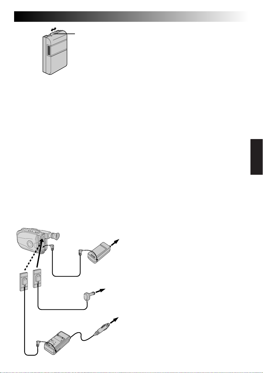
ES 9
Indicador de carga
INDICADOR DE CARGA
Se incorpora un indicador de carga sobre la batería
para ayudarle a recordar si ha sido cargada o no.
Los dos colores indicadores (rojo y negro), le
permiten seleccionar la carga y la descarga.
•La batería BN-V18U no tiene un indicador de
carga.
NOTAS:
●
El tiempo de grabación por carga depende de factores tales como el tiempo de activación del modo de
grabación/pausa y la frecuencia de accionamiento del zoom. Lo más seguro es tener baterías de repuesto.
●
Los tiempos de carga indicados en la página 4 son para la batería completamente descargada, y los
tiempos de descarga son para la batería completamente cargada.
●
Los tiempos de carga y de descarga varían dependiendo de la temperatura ambiente y el estado de la
batería.
●
Recuerde colocar el marcador de carga después de cargar la batería o después de extraer la descargada de
su cámara de video.
●
Efectúe la función REFRESH después de un mínimo de 5 cargas.
●
Mientras el cable de alimentación del adaptador de CA/cargador está desconectado de la toma de
corriente de alterna es posible descargar la batería presionando el interruptor REFRESH. Durante ese
momento, el adaptador de CA/cargador no carga la batería. Al terminar la descarga, extraiga la batería del
adaptador de CA/cargador para almacenarla.
●
Las altas temperaturas pueden dañar la batería, por eso, utilícela en un lugar con buena ventilación. No
permita que se descargue dentro de un lugar cerrado tal como una bolsa.
●
Si usted para de cargar o descargar la batería en medio del proceso, asegúrese de extraerla antes de
desconectar el cable del adaptador de CA.
●
Extraiga la batería del adaptador inmediatamente después de descargarla.
●
Para evitar interferencia con la recepción, no utilice el adaptador/cargador de CA cerca de una radio.
●
Asegúrese de desenchufar el cable de CC después de cargar o descargar la batería.
●
El indicador CHG. puede no encenderse correctamente con una batería nueva, o cuando la misma ha
sido almacenada durante un largo período. En este caso extraiga y recoloque la batería para cargarla. El
indicador CHG. debe encenderse durante la recarga, de lo contrario póngase en contacto con su agente
JVC más cercano.
USO DE LA BATERIA DEL AUTOMOVIL
Utilice el cable opcional para batería del automóvil
o el cargador/adaptador de la batería del automóvil
(conéctelo como se muestra en la ilustración de la
izquierda).
NOTAS:
●
Cuando utilice la batería del automóvil deje el
motor en marcha ralenti.
●
El cargador opcional de la batería del automóvil
(BH-V3U) puede también ser usado para cargar la
batería.
●
Cuando utilice el cargador opcional de la batería
del automóvil o el cable de la batería del
automóvil (AP-V7U), refiérase al librillo de
instrucciones correspondiente.
USO DE ALIMENTACION CON CA
Utilice el adaptador de CA (conectado como se
muestra en la ilustración de la izquierda).
NOTA:
El adaptador/cargador de CA se caracteriza por un
selector automático de voltaje con límites de CA
que van de 110 a 240 V.
Terminal
DC OUT
Al jack de
entrada
de CC
Cable de CC
Cable para batería
de automóvil␣
AP-V7U (opcional)
Cargador/adaptador para
batería de automóvil
BH-V3U (opcional)
A la toma de
corriente de
alterna
Adaptador/
cargador de CA
AA-V15U
Al enchufe del
encendedor de
cigarrillos
Page 68

10 ES
PREPARATIVOS
A
Inserción/extracción de la pila (litio) del reloj
Esta pila es necesaria para el funcionamiento del reloj y
para efectuar los ajustes de fecha/hora.
(cont.)
DESCONEXION DE LA
ALIMENTACION
Desconecte la alimentación de la unidad y extraiga
1
la unidad de alimentación.
ABERTURA DE LA CUBIERTA
Abra la cubierta del compartimiento de la pila del
2
reloj presionando la lengüeta de abertura.
EXTRACCION DE LA PILA
(al reemplazar)
Inserte un objeto puntiagudo no metálico entre la
3
pila y el compartimiento (A), y extraiga la pila.
INSERCION DE LA PILA
Inserte una pila de litio CR2025 empujándola, y
4
asegurándose de que el polo positivo (+) esté
apuntando hacia arriba.
CIERRE DE LA CUBIERTA
Cierre la cubierta del compartimiento hasta que
5
escuche un “clic”.
NOTA:
Ver “PRECAUCIONES DE SEGURIDAD” (Z p. 2) por
información sobre la manipulación segura de las pilas de
litio.
Page 69

ES 11
Ajuste de la fecha/hora
ACCESO A LA PANTALLA DE MENU
Primero coloque el conmutador de alimentación en
1
“CAMERA”. Gire el disco selector hacia cualquier
posición exceptuando AUTO LOCK, luego presione
el disco de avance MENU.
Disco selector
Disco de
avance
MENU
Visor
MENU
4
MENU END
FOCUS
EXPOSURE
DATE TIME
TELE MACRO
TAPE LENGTH
M. W. B.
ZOOM SPEED
4
NEXT
Pantalla del menú
YEAR
MONTH
DAY
TIME
EXIT
Menú de ajuste DATE/TIME
4
MENU END
FOCUS
EXPOSURE
DATE TIME
TELE MACRO
TAPE LENGTH
M. W. B.
ZOOM SPEED
4
NEXT
DATE TIME
PM 12: 00
MENU
AUTO
AUTO
JAN
OFF
T30
AUTO
FAST
1998
JAN
AUTO
AUTO
DEC
OFF
T30
AUTO
FAST
1. 98
1
25. 98
Sistema de
24 horas con
AM ó PM TIME
SELECCION DE LA FUNCION
Gire el disco de avance MENU para mover la barra
2
iluminada a “DATE/TIME” y presiónelo. Aparecerá
el menú de ajuste DATE/TIME.
•Si usted desea devolver la fecha y la hora a los
ajustes anteriores, gire el disco de avance MENU
para mover la barra iluminada a “EXIT” y
presiónelo, luego vaya al paso 6.
•Si desea ajustar sólo la hora sin cambiar la fecha,
vaya al paso 4.
AJUSTE DE LA FECHA
Gire el disco de avance MENU para mover la barra
3
iluminada hacia el item que desea ajustar y
presiónelo. Cuando el ajuste comienza a destellar,
gire el disco de avance MENU hasta que aparezca
indicado el ajuste correcto y luego presiónelo. El
ajuste deja de destellar.
•Repita este procedimiento hasta que esté
satisfecho con el ajuste de la fecha (“YEAR”,
“MONTH” y “DAY”).
AJUSTE DE LA HORA
Gire el disco de avance MENU para mover la barra
4
iluminada hacia “TIME”, luego presiónelo. Cuando
el ajuste de la hora comienza a destellar, gire el
disco de avance MENU hasta que aparezca el ajuste
correcto y luego presiónelo. Cuando el ajuste de la
hora deja de destellar y el ajuste de los minutos
comienza a destellar, gire el disco de avance MENU
hasta que aparezca indicado el ajuste correcto y
luego presiónelo. El ajuste de los minutos deja de
destellar.
ACTIVACION DEL RELOJ
Cuando ninguno de estos ajustes (YEAR, MONTH,
5
DAY, TIME) destella, gire el disco de avance MENU
para mover la barra iluminada hacia “EXIT” y
presiónelo. Aparecerá la pantalla de menú y
“MENU END” queda iluminado.
CIERRE DEL MENU
Presione el disco de avance MENU.
6
NOTA:
Para llamar al visor y al TV conectado la fecha y la hora,
vea “Inserción de fecha, hora y caracteres” (Z p. 20).
Page 70

12 ES
Botón de mode de
grabación SP-EP
PREPARATIVOS
(cont.)
Ajuste del modo de grabación
Ajústelo de acuerdo con sus preferencias.
AJUSTE DEL MODO DE GRABACION
Primero coloque el conmutador de alimentación en
1
“CAMERA”. Presione el botón SP/EP durante más de
1 segundo. La “SP” (Reproducción Estándar)
suministra mayor calidad de imagen y sonido y es
mejor para copiar, mientras que “EP” (Reproducción
Extensa) es más económica, suministrando el triple
de tiempo de grabación.
Disco selector
Visor
AUTO
AUTO
DEC
OFF
T40
AUTO
FAST
AUTO
AUTO
DEC
OFF
T20
AUTO
FAST
T40
25.98
25.98
SP
MENU
4
MENU END
FOCUS
EXPOSURE
DATE TIME
TELE MACRO
TAPE LENGTH
M. W. B.
ZOOM SPEED
4
NEXT
Pantalla de menú
TAPE LENGTH
T20
T30
T40
EXIT
Menú de ajuste TAPE LENGTH
MENU
4
MENU END
FOCUS
EXPOSURE
DATE TIME
TELE MACRO
TAPE LENGTH
M. W. B.
ZOOM SPEED
4
NEXT
Disco de
avance MENU
Indicador de
longitud de la
cinta
Indicador del
mode de
grabación
NOTA:
Si se conmuta el modo de grabación durante la
grabación, la imagen reproducida quedará borrosa en el
punto de conmutación.
Ajuste de la longitud de la cinta
Ajuste la longitud de la cinta de acuerdo con la longitud
de la cinta empleada.
ACCESO A LA PANTALLA DE MENU
Primero coloque el conmutador de alimentación en
1
“CAMERA”. Gire el disco selector hacia cualquier
posición exceptuando AUTO LOCK, luego presione
el disco de avance MENU.
SELECCION DE LA FUNCION
Gire el disco de avance MENU para mover la barra
2
iluminada hacia “TAPE LENGTH”, y luego
presiónelo. Aparecerá el menú de ajuste TAPE
LENGTH.
AJUSTE DE LA LONGITUD DE LA CINTA
Gire el disco de avance MENU para mover la barra
3
iluminada hacia el ajuste correcto. T20=20 minutos
de tiempo de grabación, T30=30 minutos y T40=40
minutos (en SP).
•Si decide devolver la longitud de la cinta al ajuste
previo, gire el disco de avance MENU para mover
la barra iluminada hacia “EXIT”.
CIERRE DEL MENU
Presione el disco de avance MENU. Reaparecerá la
4
pantalla de menú con la barra iluminada sobre
“MENU END”. Luego presione otra vez el disco de
avance MENU para cerrar la pantalla de menú.
NOTAS:
●
El tiempo restante de cinta (Z p. 17) indicado en el
visor es correcto sólo si ha seleccionado la longitud de
la cinta.
●
Una vez que haya ajustado la longitud de la cinta, la
misma permanecerá incambiada si el disco selector es
devuelto a la posición AUTO LOCK.
Page 71
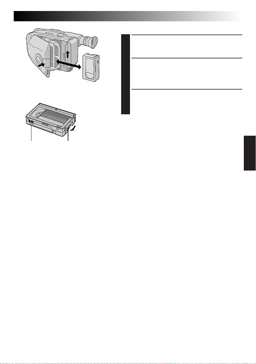
ES 13
Colocación y extracción de un cassette
ABERTURA DEL PORTACASSETTE
Deslice EJECT hasta que el portacassette se abra. No
1
1
3
3
2
2
ejerza fuerza para abrirlo.
INSERCION/EXTRACCION DEL
CASSETTE
Asegúrese de que la etiqueta esté apuntando hacia
2
afuera.
CIERRE DEL PORTACASSETTE
Presione PUSH y asegúrese de que el portacassette
3
quede cerrado y bloqueado.
Protección
contra borrado
Girar para
eliminar la
distensión.
Rueda dentada
NOTAS:
●
El portacassette no puede ser abierto a menos que la
unidad de alimentación esté colocada.
●
Asegúrese de que la cinta no está floja cuando coloca
el cassette. Si está floja, gire el engranaje del cassette
en la dirección de la flecha para tensionar la cinta.
●
Asegúrese de que la lengüeta de protección de borrado
esté en la posición que permite la grabación. De lo
contrario, deslice la lengüeta. Algunos cassettes tienen
lengüetas extraíbles. Si la lengüeta ha sido extraída,
cubra el orificio con cinta adhesiva.
●
El portacassette no puede ser abierto mientras la
cámara de video está en el modo de grabación.
Page 72

14 ES
Botón del zoom motorizado
Botón de inicio/parada de grabación
3
PREPARATIVOS
Ajuste de la empuñadura
AGRANDAMIENTO DEL LAZO
Separe las cintas Velcro.
1
INSERCION DE LA MANO
Pase la mano derecha a través del bucle y sujete la
2
empuñadura.
AJUSTE DE LA LONGITUD DE LA
CORREA
Ajústela de tal manera que el pulgar y los dedos
3
puedan operar fácilmente el botón de inicio/parada
de grabación y el botón del zoom motorizado.
Recoloque la cinta Velcro.
Ajuste del visor
POSICIONAMIENTO DEL VISOR
Ajuste el visor manualmente para la mejor
1
visibilidad (vea la ilustración a la izquierda).
(cont.)
1
1
2
2
Coloque POWER en “CAMERA”.
SELECCION DEL MODO
Coloque el conmutador de alimentación en
2
CAMERA.
AJUSTE DE LA DIOPTRIA
Gire el control de ajuste de la dioptría hasta que las
3
indicaciones en el visor queden claramente
enfocadas.
Page 73

2
3
1
1
ES 15
Colocación de la correa para el hombro
COLOCACION DE LA CORREA
Siguiendo las indicaciones de la ilustración de la
1
izquierda, enhebre la correa a través del ojal
superior 1, luego dóblela y enhébrela a través de la
hebilla 2. Repita el procedimiento para colocar el
otro extremo de la correa en el otro ojal 3,
asegurándose de que la correa no quede retorcida.
AJUSTE DE LA LONGITUD
Ajústela como se muestra en la indicación de la
2
izquierda 1.
Montaje del trípode
ALINEACION Y APRIETE
Alinee el tornillo y el perno de dirección de la
1
cámara en el trípode con el receptáculo de montaje
de la cámara de video y el orificio del perno. Luego
apriete el tornillo.
PRECAUCION:
Cuando utilice un trípode, asegúrese de abrir y
de extender totalmente las patas del mismo para
estabilizar la cámara de video. Para evitar daños
causados por su caída, no utilice trípodes
pequeños.
Page 74

16 ES
Conmutador LENS COVER
Conmutador
de alimentación
Botón de inicio/parada
Lámpara testigo
(Se enciende mientras
está grabando)
Indicador de
alimentación
GRABACION
Grabación básica
NOTA:
Usted primero debe haber efectuado los procedimientos
listados abajo. De lo contrario efectúelos antes de
continuar.
●
Alimentación (Z p. 8)
●
Ajuste del modo de grabación y de la longitud de la
cinta (Z p. 12)
●
Ajuste de la empuñadura (Z p. 14)
COLOCACION DEL CASSETTE
Deslice EJECT para abrir el portacassette, luego
1
inserte el cassette con la etiqueta apuntando hacia
afuera. Presione PUSH para asegurarse de que el
portacassette esté cerrado y bloqueado.
ACTIVACION DEL MODO DE
ESPERA DE GRABACION
Deslice el conmutador de abertura/cierre LENS
2
COVER para abrir el cubreobjetivo y luego coloque
el conmutador de alimentación en CAMERA.
•Se enciende el indicador de alimentación y la
cámara de video ingresa en el modo de espera de
grabación.
•La escena a la que usted está apuntando aparece
en la pantalla del visor con la palabra “PAUSE”
superpuesta en la misma.
INICIO DE LA FILMACION
Presione el botón de inicio/parada de grabación.
3
•En el visor aparece “
está en progreso.
REC
” mientras la grabación
Page 75
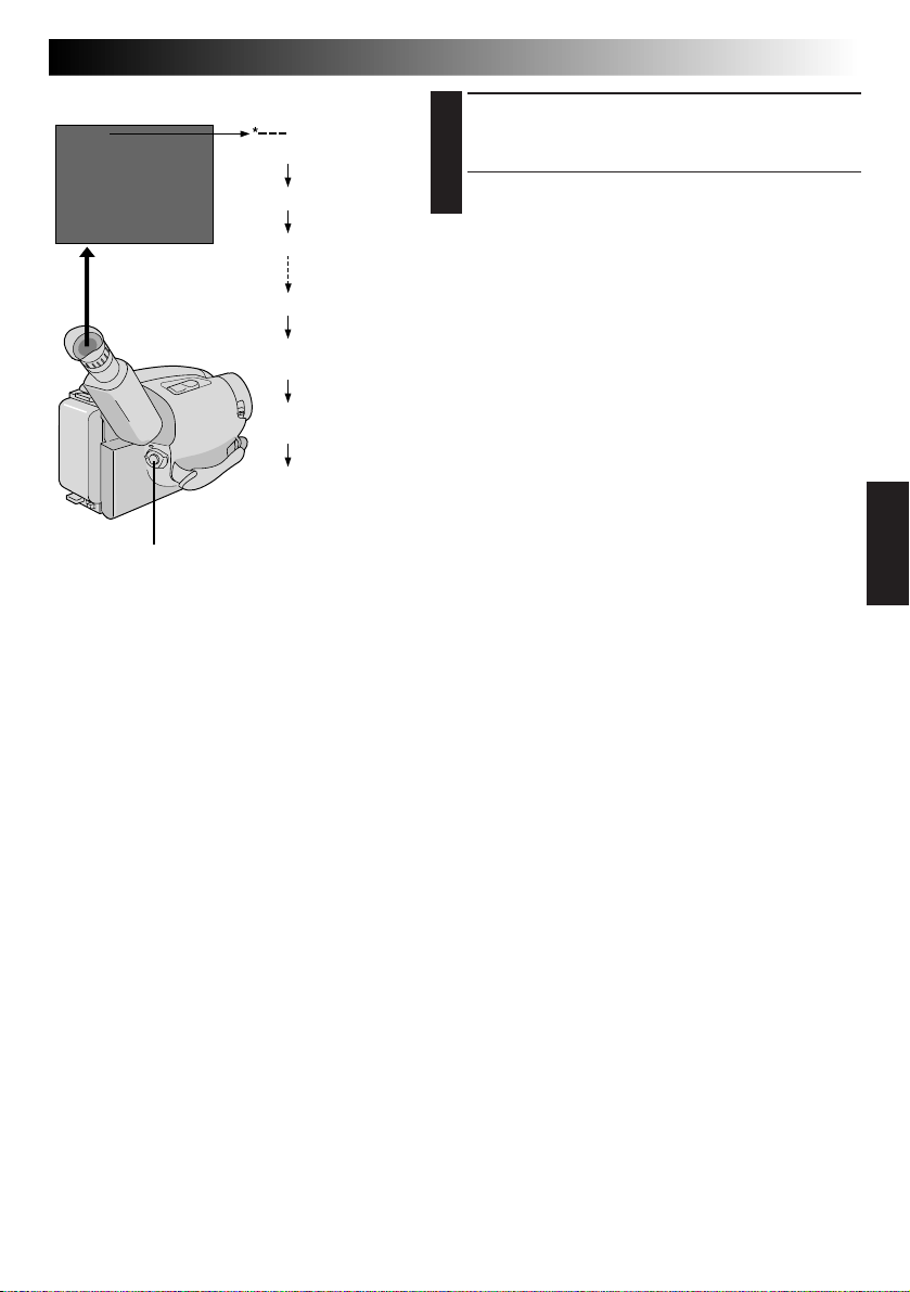
El indicador de tiempo restante de la cinta
25MIN
MIN
(Está calculándose)
120MIN
PARADA DE LA GRABACION
Presione otra vez el botón de inicio/parada de
4
grabación.
•La cámara de video vuelve a establecerse en el
modo de espera de grabación.
ES 17
Botón de inicio/parada
119MIN
3MIN
2MIN
(Destellea)
1MIN
(Destellea)
0MIN
(Destellea)
NOTAS:
●
El portacassette no puede ser abierto a menos que la
unidad de alimentación esté colocada.
●
Puede haber un retraso después que usted desliza
EJECT hasta que se abre el portacassette. No lo fuerce.
●
El tiempo restante indicado es aproximado.
●
El tiempo requerido para calcular la longitud restante
de la cinta y la precisión del cálculo pueden variar
dependiendo del tipo de cinta utilizada.
●
El indicador de tiempo restante de la cinta indicado es
correcto sólo si ha seleccionado la longitud de la cinta
(Z p. 12).
●
“TAPE END” aparece cuando la cinta llega al fin y la
alimentación se desconecta automáticamente si se deja
la unidad en esta condición durante 5 minutos.
“TAPE END” también aparece cuando se coloca un
cassette cuya cinta está en el fin.
●
Si el modo de pausa de grabación continúa activado
durante 5 minutos y no opera el zoom o cualquier otra
función, la alimentación de la cámara de video se
desconecta automáticamente. Coloque el conmutador
de alimentación en “POWER OFF” y vuelva a
colocarlo en “CAMERA” para activar otra vez la
cámara de video.
●
Si presiona el botón de inicio/parada de grabación
después de que el modo de espera de grabación ha
estado activado durante más de 5 minutos, puede que
la grabación no se inicie inmediatamente.
●
Si está grabando un cassette a partir de la mitad de éste
(tal como cuando la cinta es extraída y reinsertada
durante la grabación), utilice la función de retoma
(Z p. 19), para encontrar el fin de la última grabación
que efectuó para no borrar nada de la misma.
●
La advertencia del cubreobjetivo (LENS COVER)
parpadea durante 5 segundos aproximadamente
cuando se conecta la alimentación de la cámara de
video, cuando el cubreobjetivo está cerrado.
Page 76

18 ES
Acercamiento de la imagen
Botón del zoom motorizado
Disco selector
4
MENU END
FOCUS
EXPOSURE
DATE TIME
TELE MACRO
TAPE LENGTH
M. W. B.
ZOOM SPEED
4
NEXT
Pantalla de menú
ZOOM SPEED
FAST
SLOW
EXIT
Menú de ajuste ZOOM SPEED
Alejamiento de la imagen
Barra indicadora
de zoom
Indicador de nivel
zoom
Disco de
avance MENU
Visor
MENU
AUTO
AUTO
JAN
1.98
OFF
T30
AUTO
FAST
GRABACION
FUNCION: Zoom
PROPOSITO: Para producir el efecto de extensión/
OPERACION:
NOTAS: ●
retracción del zoom o un cambio
instantáneo en la amplificación de la
imagen.
El circuito digital duplica la amplificación
máxima de 22 aumentos ofrecida por el
zoom óptico. Este sistema es llamado zoom
digital.
Extensión del zoom
Presione “T” en el botón del zoom
motorizado.
Retracción del zoom
Presione “W” en el botón del zoom
motorizado.
n La velocidad de zoomado puede ser
ajustada. Hay un total de 4 velocidades de
zoom disponibles. 2 velocidades pueden
ser seleccionadas dependiendo de cuán
fuertemente se presione el botón del zoom
motorizado (presione el botón
completamente para velocidad normal,
presiónelo levemente para baja
velocidad). También se pueden
seleccionar 2 niveles de velocidad (FAST/
SLOW) puede ser seleccionado en el
menú ZOOM SPEED dependiendo de la
velocidad que usted prefiera.
Las combinaciones de las velocidades de
zoomado están mostradas en la tabla de
abajo.
Cambio de la ZOOM SPEED en el menú.
1)Coloque el disco selector en cualquier
posición exceptuando AUTO LOCK y
presione el disco de avance Menu.
Aparecerá la pantalla de menú.
2)Gire el disco de avance MENU para
mover la barra iluminada hacia “ZOOM
SPEED”, luego presiónelo. Aparecerá el
menú de ajuste ZOOM SPEED.
3)Gire el disco de avance MENU para
mover la barra iluminada a la velocidad
deseada y presiónelo dos veces.
Desaparecerá la pantalla de menú y el
ajuste queda completado.
El enfoque puede desestabilizarse durante
el zoomado. En este caso, ajuste el zoom
mientras el modo de espera de grabación
está activado, bloquee el enfoque
empleando el enfoque manual (Z p. 31),
luego extienda o retraiga el zoom en el
modo de grabación.
●
El indicador (n) de nivel del zoom se
mueve durante el zoomado. Una vez que
el indicador de nivel zoom llega a la parte
superior de la barra indicadora del zoom,
la amplificación desde ese punto es
realizada a través de procesamiento digital.
●
Durante el zoomado digital, la calidad de
la imagen puede deteriorarse. Para
desactivar el zoom digital, ajuste
“D. ZOOM” en “OFF” en la pantalla de
menú (Z p. 29).
Funciones básicas
Velocidad de zoomado (1 – 4 en orden de velocidad)
“ZOOM SPEED”
en la pantalla de
menú
Presión del botón
del zoom motorizado
totalmente levemente
FAST 1 (máxima) 3
SLOW 2 4 (mínima)
: Cuando el disco selector está ajustado en AUTO LOCK.
Page 77
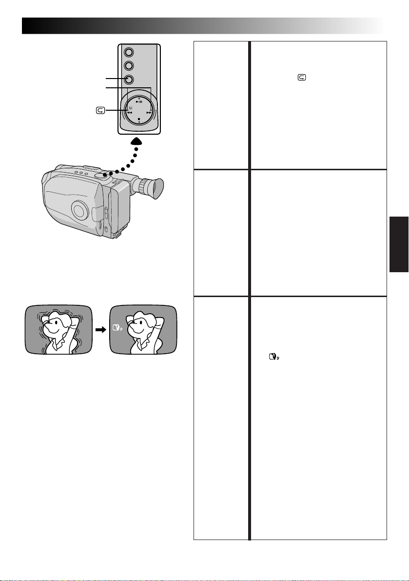
P. STABILIZER
RETAKE (R/F)
ES 19
FUNCION: Revisión rápida
PROPOSITO: Para confirmar el fin de la última
OPERACION: 1) Presione “
NOTA:
FUNCION: Retoma
PROPOSITO: Para regrabar ciertos segmentos.
OPERACION: 1) Asegúrese de que la cámara de video
NOTA:
FUNCION: Estabilizador de imagen
PROPOSITO: Para compensar las imágenes inestables
OPERACION: 1) Presione P. STABILIZER. Aparecerá
NOTAS: ● La estabilización precisa puede no
grabación.
rápidamente con el modo de espera
de grabación activado.
n La cinta es rebobinada durante 2
segundos aproximadamente y
reproducida automáticamente,
luego se detiene en el modo de
pausa de grabación para la
próxima filmación.
” y suéltelo
Es posible que haya distorsión al inicio
de la reproducción, esto es normal.
esté en el modo de pausa de
grabación.
2) Presione cualquiera de los botones
RETAKE para llegar al punto deseado
para iniciar la nueva grabación. Al
presionar “F” avanza rápidamente la
cinta y al presionar “R” la rebobina.
3) Para iniciar la grabación presione el
botón de inicio/parada de grabación.
Es posible que haya interferencia
durante la retoma, esto es normal.
causadas por el movimiento de la
cámara, particularmente durante la
gran amplificación.
“
”.
n Para desactivar el estabilizador de
imagen, presione otra vez P.
STABILIZER. La indicación
desaparece.
ser posible si el movimiento de la
mano es excesivo, o en los siguientes
casos:
•
Cuando filma sujetos con rayas
verticales u horizontales
•
Cuando filma sujetos oscuros o
poco iluminados.
•
Cuando los sujetos filmados tienen
mucha iluminación por detrás.
•
Cuando las escenas filmadas se
mueven en diferentes direcciones.
•
Cuando las escenas filmadas tienen
fondos con poco contraste.
●
Desactive el estabilizador de imagen
cuando graba con la cámara
montada en un trípode.
Page 78

20 ES
DATE/TIME
Disco selector
Indicación de fecha
Indicación de hora
Indicación de fecha/hora
Modo de grabación automática de la fecha
Modo de apagado de fecha (Sin indicación)
Indicación de fecha
DEC 25.98
Indicación de hora
PM10:50:00
Indicación de
fecha/hora
DEC 25.98
PM10:50:00
Indicación
Grabación automática
de la fecha
Grabación automática
de la fecha
Fecha automática
grabada
AUTO DATE
DEC 25.98
GRABACION
Funciones básicas (cont.)
FUNCION: Inserción de fecha/hora
PROPOSITO: Para llamar la fecha y hora en el
visor o en un monitor a color
conectado, y para grabarlos manual
o automáticamente.
OPERACION: 1) Gire el disco selector a cualquier
posición exceptuando AUTO
LOCK.
2) Seleccione un modo de indicación
presionando repetidamente DATE/
TIME con espera de grabación
activada para circular por los
modos como se muestra en la
ilustración a la izquierda.
n Usted debe haber efectuado el
procedimiento de ajuste de
fecha/hora (Z p. 11). Si no lo ha
realizado, efectúelo antes de
continuar.
NOTAS:
INDICACION
●
La indicación seleccionada puede
ser grabada.
●
Si no desea grabar la indicación,
seleccione el modo de fecha
desactivada antes de filmar.
●
Si desea borrar la indicación
durante la filmación, presione
DATE/TIME.
●
Para llamar la indicación otra vez,
active el modo de espera de
grabación y presione
repetidamente DATE/TIME hasta
que aparezca la indicación
deseada.
GRABACION AUTOMATICA DE LA
FECHA
●
Su cámara de video graba
automáticamente la fecha durante
5 segundos aproximadamente
después de iniciar la grabación en
las siguientes situaciones:
•
Después de cambiar la fecha.
•
Después de colocar un cassette.
•
Después de seleccionar el modo
de grabación automática de la
fecha presionando DATE/TIME.
En este modo la fecha es
reemplazada después de 5 segundos
por “AUTO DATE” pero no es
grabada.
●
El ajuste del disco selector en
AUTO LOCK activa siempre el
modo de grabación automática de
la fecha y desactiva todos los otros
modos.
Page 79
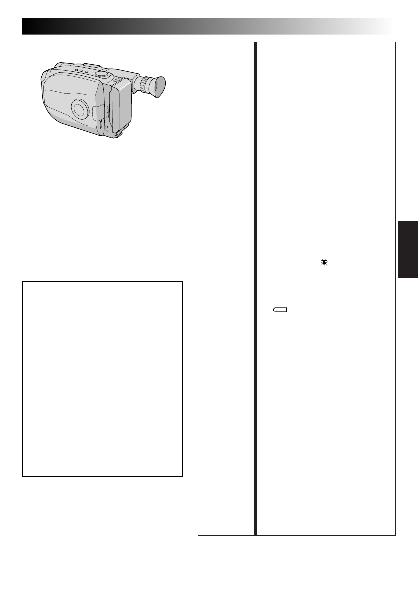
LIGHT OFF/AUTO/ON
PELIGRO
n El foco de video puede calentarse
extremadamente. No lo toque cuando
está encendido ni inmediatamente
después de apagarlo, de lo contrario
podrá sufrir quemaduras graves.
n No coloque la cámara de video dentro
del estuche para transporte
inmediatamente después de emplear el
foco de video ya que continuará
caliente durante algún tiempo.
n Cuando emplea la cámara de video
mantenga una distancia de 30 cm.
aprox. entre el foco de video y las
personas u objetos.
n No la emplee cerca de materiales
inflamables o explosivos.
n Se recomienda consultar con su
distribuidor JVC más cercano para
reemplazar el foco de video.
ES 21
FUNCION: Foco de video
PROPOSITO: Para iluminar la escena cuando la
OPERACION: 1) Coloque el conmutador LIGHT
NOTAS: ●
luz natural es insuficiente.
OFF/AUTO/ON como sea
necesario:
ON : Mantiene el foco de video
AUTO : Enciende el foco de video
OFF : Apaga el foco de video.
n El foco de video sólo puede ser
n Cuando emplea foco de video se
n Cuando no emplea el foco de
encendido mientras la
cámara está activada.
automáticamente cuando
la cámara de video capta
que el sujeto está
insuficientemente
iluminado.
usado cuando la alimentación de
la cámara de video está
conectada.
recomienda colocar el balance
del blanco (Z p. 33) en el modo
HALOGEN ( ).
video, apáguelo para ahorrar
batería.
Aunque el indicador de la batería
( ) no destelle si la carga está
baja, la cámara de video puede
desconectarse automáticamente
cuando usted enciende el foco de
video, o cuando comienza a
grabar con el foco de video
encendido.
●
Cuando se coloca el conmutador
LIGHT OFF/AUTO/ON
en
“AUTO”:
•
Dependiendo de las condiciones
de iluminación, el foco de video
puede encenderse y apagarse
repetidamente, en este caso,
encienda manualmente el foco
de video con el conmutador
LIGHT OFF/AUTO/ON.
•
Mientras el modo de deportes u
obturación de alta velocidad
(Z p. 23) están activados, es
muy probable que el foco de
video quede encendido.
•
Con el modo atardecer (Z p. 23)
activado, el foco de video no se
encenderá.
Page 80

22 ES
1 segundo más tarde se activa el modo.
SEPIA
Disco selector
Después de 1 s.
Visor
0
0
0
2
/
1
EFFECT
WIDE TITLE
Marca
K
C
O
L
T
U
O
A
SUPER
LOLUX
GRABACION
Funciones avanzadas
Programa AE con efectos especiales
Todo lo que usted tiene que hacer para acceder a una
gran variedad de efectos de filmación es girar el disco
selector.
SELECCION DE MODO
Gire el disco selector hasta que el símbolo de la
1
función que usted desea quede alineado con la
marca.
•El nombre del modo seleccionado y su indicación
aparecen durante aprox. 1 segundo. Luego el
nombre desaparece y solo permanece la
indicación. Se activa el modo.
•Cuando selecciona el modo de bloqueo
automático o el de desactivación, sólo el nombre
del modo es indicado. Luego el mismo desaparece
y el modo queda activado.
NOTAS:
●
Sólo se puede activar un efecto a la vez.
●
La pantalla se vuelve levemente rojiza cuando se
utiliza el fundido/reemplazo de imagen (Z p. 24) en el
modo sepia.
●
R
E
L
E
A
M
O
S
D
E
E
F
G
N
D
La pantalla se oscurece levemente en el modo de
obturación de alta velocidad. Utilícelo en situaciones
bien iluminadas.
●
En los modos de obturación de alta velocidad o de
deportes el color de la imagen puede ser afectado
adversamente si el sujeto está iluminado por fuentes de
luz de tipo descarga alternada tales como lámparas
fluorescentes o de vapor de mercurio.
Page 81

Indicación Indicación
en el disco en el visor
Modo
Indicación Indicación
en el disco en el visor
ES 23
Modo
LOCK AUTO LOCK
Bloqueo del
modo automático
Bloqueo del modo automático
Bloquea la cámara de video en el modo
completamente automático evitando presionar por
error los botones durante la filmación.
•En este modo los siguientes controles están
desactivados: selección de indicación DATE/TIME
y disco de avance menú.
RELEASE AUTO RELEASE
Desactivación del
modo automático
Desactivación del modo automático
Reactiva los mandos que quedaron inhabilitados
por el bloqueo de modo automático.
FG FG : FOG
Filtro electrónico
de niebla
Filtro electrónico de niebla
Hace que luzca neblinosa en blanco, como cuando
se coloca un filtro de niebla externo sobre el
objetivo. Suaviza la imagen y le da un aspecto
“fantástico”.
ND ND:ND EFFECT
Efecto ND
Efecto ND
Una niebla oscurece la imagen tal como cuando se
utiliza un filtro ND. Ayuda a contrarrestar el reflejo
sobre un sujeto.
TWILIGHT
Atardecer
Atardecer
Las escenas del atardecer y nocturnas, los fuegos
artificiales, etc., lucen más naturales y dramáticos.
Cuando selecciona el modo de atardecer ocurre lo
siguiente:
•El control de ganancia automática se desconecta.
•El balance del blanco es ajustado en “ ” (modo
de buen tiempo FINE), pero también puede ser
manualmente cambiado a otro modo (Z p. 33).
•El enfoque automático sólo queda habilitado
dentro de los límites de 10 m a infinito. Para
enfocar el sujeto cuando la distancia del mismo a
la cámara es menor de 10 m, emplee el enfoque
manual (Z p. 31).
SPORTS
Deportes
Deportes
La alta velocidad del obturador captura claramente
la acción rápida.
NEGA POSI
Negativo/positivo
Negativo/positivo
Los colores de la imagen se invierten.
SEPIA
Sepia
Sepia
La escena que está siendo filmada es grabada con
un tinte sepia (marrón rojizo), monocromático,
dándole un efecto de película antigua. Utilícelo con
el modo pantalla ancha (Z p. 25), para un aspecto
de auténtico cine clásico de Hollywood.
Modo NEGA POSI
1/2000 S 1/2000
2
Obturador con
alta velocidad
Obturador con alta velocidad (1/2000 s.)
Captura una acción más rápida que la del modo
deportes.
Page 82

24 ES
[Ej.: FADER]
Aparición gradual
Indicación de función
4
EFFECT
MOSAIC
B
K
Desactivado
(Sin indicación)
OFF
Desaparición gradual
Visor
Después de 2s.
B
K
FADER
(fundido en negro)
MOSAIC
(fundido en mosaico)
SHUTTER
(reemplazo de imagen tipo persiana)
SLIDE
(reemplazo de imagen deslizante)
GRABACION
Funciones avanzadas (cont.)
Fundido/reemplazo de imagen
Estos efectos le permiten hacer transiciones de escena estilo
profesional. La aparición gradual funciona al inicio de la
grabación y la desaparición gradual funciona al fin de la misma,
o cuando usted activa el modo de pausa de grabación.
ACTIVACION DEL MODO DE ESPERA DE
FUNDIDO O DE REEMPLAZO DE IMAGEN
Presione EFFECT para circular por los modos como se
muestra a la izquierda. Una vez que visualiza el modo
1
deseado, el mismo es seleccionado y registrado.
• El nombre del modo seleccionado y su indicación son
indicados en el visor durante 2 segundos aprox. Luego el
nombre desaparece y sólo permanece la indicación.
INICIO O FIN DE LA GRABACION
Presione el botón de inicio/parada para activar los fundidos
y los reemplazos de imagen.
2
CANCELACION DEL MODO DE
ESPERA DE FUNDIDO Y REEMPLAZO
Presione EFFECT repetidamente hasta que aparezca “OFF”.
3
• “OFF” aparecerá indicado durante 2 segundos aprox. y el
modo de espera de fundido/reemplazo será cancelado.
FADER (fundido en negro)
B
K
La imagen aparece/desaparece en una pantalla negra.
MOSAIC (fundido en mosaico)
La imagen aparece/desaparece gradualmente en/desde un efecto
de mosaico.
SHUTTER (reemplazo de imagen tipo persiana)
La pantalla negra se mueve hacia el centro de la imagen desde la
parte superior e inferior de la misma, tal como una persiana, o una
nueva imagen abre verticalmente una pantalla negra desde el centro.
SLIDE (reemplazo de imagen deslizante)
Una pantalla negra aparece desde la izquierda cubriendo
gradualmente la imagen, o una nueva imagen aparece de
derecha a izquierda.
NOTAS:
●
El mantener presionado el botón de inicio/parada de grabación
EFFECT
Botón de inicio/
parada de grabación
le permite grabar una pantalla en negro o un efecto de mosaico
si ha seleccionado el fundido tipo mosaico.
●
La pantalla se enrojece levemente al emplear el fundido/
reemplazo con sepia (
●
Con el modo de filtro de niebla electrónico (Z p. 23) activado,
cuando el fundido (sin mosaico) es activado, la imagen
aparece/desaparece en una pantalla blanca.
Z
p. 23).
NOTA (para fundido/reemplazo de imagen, pantalla ancha, super LoLux, títulos
instantáneos y estabilizador de imagen):
Cuando gira el disco selector hacia AUTO LOCK, las funciones de arriba quedan en los ajustes de fábrica (espera de
fundido/reemplazo de imagen: “OFF”, modo pantalla ancha: desactivado, super LoLux:”MAX”, título instantáneo:
desactivado, estabilizador de imagen: desactivado). Luego cuando devuelve el disco a cualquier posición exceptuando
AUTO LOCK, las funciones de arriba vuelven a los ajustes que usted seleccionó antes de ajustarlo en AUTO LOCK. Sin
embargo, si la función es conmutada durante AUTO LOCK, el modo seleccionado quedará ajustado y permanecerá sin
cambio aunque gire el disco selector a cualquier posición exceptuando AUTO LOCK.
Page 83

Visor
WIDE
SUPER LOLUX
Visor
4
S.LX
MAX
Después de 2 s.
Modo pantalla
ancha
MAX
NORM
OFF
ES 25
Pantalla ancha
Esta función le permite grabar barras negras en la parte
superior e inferior de la pantalla para producir un efecto
similar al cine tipo “pantalla ancha”.
ACTIVACION DEL MODO
PANTALLA ANCHA
Presione WIDE.
1
•Para volver a la pantalla normal, presione WIDE
otra vez.
Super LoLux (aumento de ganancia)
Se pueden efectuar grabaciones brillantes y naturales aún
áreas con poca o insuficiente iluminación.
SELECCION DEL MODO SUPER
LOLUX
Presione SUPER LOLUX repetidamente para circular
1
a través de los modos como se muestra a la
izquierda. Una vez que aparezca el modo deseado,
el mismo será activado.
•El nombre del modo es indicado durante 2
segundos aprox. y luego desaparece.
MAX : Para grabar un sujeto en un ambiente
NORM : Para grabar un sujeto en un ambiente
OFF : Le permite filmar escenas oscuras sin
oscuro. Cuando es más conveniente
filmar un sujeto con una imagen más
brillante aunque la imagen pierda un
poco de contraste.
iluminado con luz mortecina. Cuando es
más conveniente filmar con una imagen
más contrastada aunque el sujeto se
obscurezca un poco. Este ajuste es
adecuado para medir la sensibilidad de
acuerdo a EIA-639 (EIA* Estandar para
Medición de Sensibilidad de Luz
Mortecina).
*
EIA: Asociación de Industrias Electrónicas
ajuste de brillo de imagen.
Page 84

26 ES
GRABACION
Funciones avanzadas (cont.)
Títulos instantáneos
La cámara de video tiene ocho títulos almacenados en
memoria. Usted puede superponer uno de ellos sobre un
título previamente almacenado como se muestra en la
ilustración a la izquierda.
Los títulos instantáneos pueden ser llamados a la
indicación no sólo en español sino también en inglés,
francés y portugués. Cambie el ajuste en la pantalla de
menú TITLE LANG. (Z p. 27, 29).
TITLE
Visor
Indicación de título
FELIZ CUMPLEAÑOS Sin indicación
NUESTRAS VACACIONES
FELICES NAVIDADES
UN DÍA ESPECIAL
FELICES FIESTAS
NUESTRO NUEVO BEBÉ
BODA
ENHORABUENA
SELECCION DE TITULO
PREAJUSTADO
Presione TITLE repetidamente para circular a través
1
de los títulos preajustados hasta que aparezca
indicado el título deseado.
Page 85

Disco selector
Visor
MENU
4
MENU END
FOCUS
EXPOSURE
DATE TIME
TELE MACRO
TAPE LENGTH
M. W. B.
ZOOM SPEED
4
NEXT
AUTO
AUTO
DEC
OFF
T30
AUTO
FAST
Pantalla de menú 1
MOVIE MENU
4
BACK
REC TIME
INT. TIME
TALLY LAMP
TITLE LANG.
D. ZOOM
COLOR BAR
JLIP ID NO.
DEMO MODE
4
MENU END
OFF
OFF
ON
ENGLISH
ON
OFF
07
OFF
Pantalla de menú 2
TITLE LANG.
ENGLISH
FRENCH
SPANISH
PORTUGUESE
EXIT
Menú de ajuste
(ej.: TITLE LANG.)
MOVIE MENU
4
BACK
REC TIME
INT. TIME
TALLY LAMP
TITLE LANG.
D. ZOOM
COLOR BAR
JLIP ID NO.
DEMO MODE
4
MENU END
OFF
OFF
ON
FRENCH
ON
OFF
07
OFF
Pantalla normal
25.98
Disco de
avance MENU
ES 27
Uso del menú para ajuste fino
Esta cámara de video está equipada con un sistema de menú
en pantalla que simplifica muchos de los ajustes más finos de
la cámara de video.
ACCESO A LA PANTALLA DE MENU
Gire el disco selector hacia cualquier posición
exceptuando AUTO LOCK, luego presione el disco de
1
avance MENU. Aparecerá la pantalla del menú.
SELECCION DE LA FUNCION
Gire el disco de avance MENU para colocar la barra
iluminada sobre la función deseada.
2
•Cuando la barra iluminada llega al fondo de la
pantalla de menú 1, la pantalla de menú 2 aparece
automáticamente. Cuando la barra iluminada llega a
la parte superior de la pantalla 2 de menú, aparece
indicada automáticamente la pantalla 1 de menú.
•Si no puede encontrar el ajuste que desea en la
pantalla de menú, coloque la barra iluminada sobre
“MENU END”, y luego vaya al paso 5.
AJUSTE
Presione el disco de avance MENU. Aparecerá el menú
de ajuste de la función seleccionada. El procedimiento
3
de ajuste depende de la función que usted selecciona.
Si usted selecciona “FOCUS”, “EXPOSURE” o
“DATE/TIME” . . .
..... Vea las páginas respectivas (FOCUS: Z p. 30, 31,
EXPOSURE:
Si usted selecciona “JLIP ID NO.” . . .
..... Presione el disco de avance MENU para que el
número destelle, luego gírelo hasta que aparezca el
número deseado y presiónelo. Luego gire el disco
de avance MENU para mover la barra iluminada
hacia “EXIT”.
Si usted selecciona cualquier otra función . . .
..... Gire el disco de avance MENU para mover la barra
iluminada hacia el ajuste deseado.
• Si decide regresar al ajuste anterior, gire el disco
de avance MENU para mover la barra iluminada
hacia “EXIT”.
FIN DEL AJUSTE
Presione el disco de avance MENU. Reaparecerá la
pantalla de menú y la barra iluminada quedará sobre
4
“MENU END”.
CIERRE DEL MENU
Presione el disco de avance MENU. Reaparecerá la
pantalla normal.
5
NOTA:
La función de menú exceptuando “FOCUS” y “EXPOSURE”
no están disponibles mientras el modo de grabación está
activado.
Z p. 32, DATE/TIME: Z p.11).
Page 86

28 ES
Explicación de la pantalla de menu
GRABACION
Funciones avanzadas (cont.)
FOCUS Ajusta el enfoque automáticamente.
EXPOSURE Ajusta la exposición automáticamente.
DATE/TIME Le permite ajustar la fecha y hora actuales (Z p. 11).
TELE MACRO Usualmente la distancia al sujeto dónde el objetivo está
TAPE LENGTH Le permite ajustar la longitud de la cinta dependiendo de la cinta empleada
M.W.B. El sistema sensor automático de temperatura de color de la
ZOOM SPEED Le permite ajustar la velocidad de zoomado (Z p. 18).
AUTO
MANU
AUTO
MANU
OFF
ON
(Z p. 12).
AUTO
: FINE
: CLOUD
: HALOGEN
MWB
FAST
SLOW
Le permite ajustar el enfoque manualmente (Z p. 30, 31).
Le permite ajustar la exposición manualmente (Z p. 32).
enfocado depende de la amplificación del zoom. A menos que
haya una distancia mayor a 1 m hasta el sujeto, el objetivo
queda desenfocado en el ajuste telefoto máximo. Cuando lo
coloca en “ON” puede filmar un sujeto tan grande como
posible a una distancia de 60 cm.
•Dependiendo de la posición del zoom, el objetivo puede
quedar desenfocado.
cámara de video capta la temperatura del color de la
iluminación ambiente para el ajuste automático del balance del
blanco. Sin embargo, el ajuste preciso del color no es posible
en las siguientes condiciones:
•Cuando un objeto tiene varios tonos del mismo color.
•Cuando un objeto predominantemente rojo o marrón es
filmado al aire libre.
En estos casos utilice los filtros de preajuste incorporados en la
cámara de video para el ajuste del balance del blanco
(
Z p. 33).
= Ajuste de fábrica y cuando el disco selector está ajustado en AUTO LOCK
Page 87

ES 29
REC TIME Esta función le permite ajustar los parámetros para la animación y grabación con
INT. TIME Esta función le permite ajustar los parámetros para el autodisparador (Z p. 34) y
TALLY LAMP ON La lámpara testigo se enciende indicando el inicio de la
TITLE LANG. Le permite seleccionar el idioma (ENGLISH, FRENCH, SPANISH o PORTUGUESE)
D. ZOOM ON Permite el uso del zoom digital. Procesando digitalmente y
COLOR BAR OFF No muestra barras de color. Se graba la pantalla normal.
JLIP ID NO. Este número será necesario en el futuro cuando se conecte la cámara de video a un
DEMO MODE OFF La demostración automática no se realiza.
lapso de tiempo (Z p. 35).
grabación con lapso de tiempo (Z p. 35).
grabación.
OFF La lámpara testigo permanece apagada.
de los títulos instantáneos (Z p. 25).
ampliando las imágenes, el zoomado es posible desde 22
aumentos (límite del zoom óptico) a un máximo de
amplificación digital de 44 aumentos.
OFF El zoom digital no está disponible. Sólo el zoom óptico (22
aumentos máximo) puede funcionar. Cuando lo ajusta en "OFF"
durante el zoomado digital, la amplificación del zoom cambia
a 22 aumentos.
ON Hace que desaparezca la pantalla normal, mostrando barras de
color. Grabando barras de color al principio o al fin de una
cinta, las cintas que graba tendrán un efecto similar al de las
producciones profesionales.
NOTA:
Mientras las barras de color están indicadas, las otras funciones
de la cámara de video están inhabilitadas.
computador utilizando el terminal JLIP. Los números van de 01 a 99. El ajuste de
fábrica es 07.
ON Demuestra ciertas funciones tales como fundido, títulos
instantáneos, etc. Cuando coloca “DEMO MODE” en “ON” y
cierra la pantalla de menú, se inicia la demostración.
NOTAS:
● Cuando coloca en la cámara de video una cinta con la
lengüeta de protección de grabación en una posición tal que
permite la grabación, la demostración no está disponible.
● Desconectando la alimentación de la cámara de video o
insertando una cinta cuya lengüeta de protección contra
borrado está en la posición que permite la grabación, “DEMO
MODE” queda automáticamente ajustado en “OFF”.
● Durante la demostración todas las funciones quedan
inhabilitadas, exceptuando el zoom.
= Ajuste de fábrica y cuando el disco selector está ajustado en AUTO LOCK
Page 88

30 ES
Zona de detección
del enfoque
GRABACION
Funciones avanzadas (cont.)
Enfoque
Enfoque automático
El sistema de enfoque automático de gama completa de
la cámara de video ofrece capacidad para filmar
continuadamente desde primer plano a infinito. Sin
embargo, el enfoque correcto puede no ser posible en las
situaciones listadas abajo (en cuyo caso es necesario
utilizar el enfoque manual):
•Cuando hay dos sujetos superpuestos en la misma
escena.
•Cuando la iluminación es insuficiente.*
•Cuando el sujeto no está contrastado (diferencia en
brillo y oscuridad), tales como una pared plana de un
sólo color o un cielo azul despejado.*
•Cuando un objeto oscuro es apenas visible.*
•Cuando la escena contiene detalles diminutos o
detalles idénticos que se repiten regularmente.
•Cuando la escena es afectada por los rayos solares o
por la luz que se refleja en un cuerpo de agua.
•Cuando filma una escena con un fondo que tiene alto
contraste.
* La advertencia de poco contraste “
NOTAS:
●
Si el objetivo está manchado o sucio, el enfoque
correcto es imposible. Mantenga el objetivo limpio
limpiándolo con un trozo de paño suave si se ensucia.
Cuando haya condensación, límpielo con un paño
suave o espere a que se seque naturalmente.
●
Cuando filma un sujeto cercano al objetivo, primero
retraiga el zoom (Z p. 18). Si extiende el zoom en el
modo de enfoque automático, la cámara de video
podrá retraer el zoom automáticamente dependiendo
de la distancia entre la cámara de video y el sujeto.
Cuando se activa “Tele Macro” (Z p. 28) el zoom
enfoca automáticamente una toma granangular.
” aparece.
Page 89

Disco selector
Visor
MENU
4
MENU END
FOCUS
EXPOSURE
DATE TIME
TELE MACRO
TAPE LENGTH
M. W. B.
ZOOM SPEED
4
NEXT
Pantalla de menú
AUTO
MANU
EXIT
Pantalla de menú de enfoque
FOCUS
AUTO
AUTO
DEC
OFF
T30
AUTO
FAST
25.98
Disco de
avance MENU
Sin indicación
durante la
grabación
Sin indicación
durante la
grabación
ES 31
Enfoque manual
NOTA:
Usted debe haber efectuado los ajustes necesarios del
visor (Z p. 14). Si no los ha realizado, efectúelos antes
de continuar.
ACCESO A LA PANTALLA DE MENU
Gire el disco selector hacia cualquier posición
1
exceptuando AUTO LOCK, luego presione el disco
de avance MENU. Aparecerá la pantalla del menú y
la barra iluminada colocada sobre “FOCUS”.
ACCESO A LA PANTALLA DE
MENU DE ENFOQUE
Presione el disco de avance MENU.
2
ACCESO A ENFOQUE MANUAL
Gire el disco de avance MENU para mover la barra
3
iluminada a “MANU” y luego presiónelo. Aparecerá
“ ” y “ ”. El enfoque queda bloqueado en este
punto.
AJUSTE DE ENFOQUE
Para alejar el sujeto . . .
4
Gire hacia arriba el disco de avance MENU.
Aparecerá “ ” destellando.
Vaya al paso 5.
Para acercar el sujeto . . .
Gire hacia abajo el disco de avance MENU.
Aparecerá “ ” destellando.
Vaya al paso 5.
Pantalla de enfoque manual
FIN DEL AJUSTE DE ENFOQUE
Presione el disco de avance MENU. La pantalla de
5
menú reaparece y la barra iluminada es colocada
sobre “MENU END”.
CIERRE DEL MENU
Presione el disco de avance MENU. Desaparecerá la
6
pantalla de menú y reaparecerá “ ” indicando
que el enfoque está bloqueado.
NOTAS:
●
Para volver al enfoque automático seleccione “AUTO”
en el paso 3.
●
Para reajustar el enfoque manual, repita el
procedimiento desde el paso 1.
●
Asegúrese de enfocar el objetivo en la posición de
extensión máxima cuando utilice el modo de enfoque
manual. Si usted enfoca un sujeto en posición gran
angular, no será posible obtener imágenes bien
contrastadas cuando retrae el zoom ya que la
profundidad de campo se reduce a mayor longitud
focal.
●
Cuando el nivel de enfoque no puede ser ajustado a
más lejos o más cerca, parpadeará “
” o “ ”.
Page 90

32 ES
Disco selector
Visor
MENU
4
MENU END
FOCUS
EXPOSURE
DATE TIME
TELE MACRO
TAPE LENGTH
M. W. B.
ZOOM SPEED
4
NEXT
Pantalla de menú
EXPOSURE
AUTO
MANU
EXIT
Pantalla de menú de
exposición
AUTO
AUTO
DEC
OFF
T30
AUTO
FAST
25.98
00
GRABACION
Disco de
avance MENU
Sin indicación
durante la
grabación
Sin indicación
durante la
grabación
Contador de
nivel de control
de exposición
Funciones avanzadas (cont.)
Control de exposición
Esta función ajusta automáticamente el iris para obtener
la mejor calidad disponible de imagen, pero usted puede
desactivarla y efectuar el ajuste manualmente.
ACCESO A LA PANTALLA DE
MENU
Gire el disco selector hacia cualquier posición
1
exceptuando AUTO LOCK, luego presione el disco
de avance MENU. Aparecerá la pantalla del menú.
ACCESO A LA PANTALLA DEL
MENU DE EXPOSICION
Gire el disco de avance MENU para mover la barra
2
iluminada sobre “EXPOSURE” y presiónelo.
ACCESO A LA EXPOSICION
MANUAL
Gire el disco de avance MENU para mover la barra
3
iluminada a “MANU”, luego presiónelo. Aparecerá
“00” (contador del nivel de control de exposición).
AJUSTE DE LA EXPOSICION
Para iluminar la imagen . . .
4
Gire hacia arriba el disco de avance MENU. El
contador de nivel de control de exposición aumenta
(+06 máximo).
Vaya al paso 5.
Para oscurecer la imagen . . .
Gire hacia abajo el disco de avance MENU. El
contador de nivel de exposición decrece (–06
máximo).
Vaya al paso 5.
FIN DEL AJUSTE DE EXPOSICION
Presione el disco de avance MENU. Reaparecerá la
5
pantalla de menú con la barra iluminada en “MENU
END”.
Pantalla de exposición manual
Para iluminar la imagen
–
06
Para oscurecer la imagen
+
06
CIERRE DEL MENU
Presione el disco de avance MENU. La pantalla
6
desaparece y reaparece el contador de nivel del
control de exposición indicando que la exposición
está ajustada.
NOTAS:
●
Para volver al ajuste de fábrica, seleccione “AUTO” en
el paso 3.
●
Para reajustar la exposición, repita el procedimiento
desde el paso 1.
Page 91

Visor
MENU
4
MENU END
FOCUS
EXPOSURE
DATE TIME
TELE MACRO
TAPE LENGTH
M. W. B.
ZOOM SPEED
4
NEXT
M. W. B.
AUTO
: FINE
: CLOUD
: HALOGEN
MWB
EXIT
AUTO
AUTO
DEC
OFF
T30
AUTO
FAST
Disco selector
Pantalla de menú
25.98
Pantalla de
M.W.B.
Disco de
avance
MENU
NOTAS:
●
Para conmutar al ajuste automático del
balance del blanco, coloque M.W.B. en la
pantalla de menú en “AUTO” o gire el disco
selector hacia “AUTO LOCK”.
●
Reajuste el balance del blanco cuando la luz
haya cambiado, cuando la alimentación de
la cámara de video sea desconectada y
conectada otra vez, o cuando haya
cambiado la posición del disco.
●
Cuando ajusta la escena colocando un papel
coloreado frente al sujeto en el paso 1 de
“MWB”, esta unidad hace su temperatura de
color normal para el balance automático del
blanco. De esta manera usted podrá disfrutar
de la filmación con diferentes colores. Por
ejemplo, cuando la ajusta en rojo, azul o
amarillo, la imagen se vuelve de un color
aproximado al verde, naranja o morado
respectivamente.
●
Es útil conectar su cámara de video a un
monitor a color cuando ajusta el balance del
blanco (Z p. 37).
ES 33
Ajuste manual del balance del blanco (M.W.B.)
Usualmente, el balance del blanco se es
automáticamente ajustado automáticamente. Sin
embargo, el usuario avanzado de la cámara de video
puede preferir controlar esta función manualmente y
lograr un color/tinte de reproducción más profesional.
ACCESO A LA PANTALLA DE MENU
Gire el disco selector a cualquier posición
exceptuando AUTO LOCK, luego presione el disco
1
de avance MENU. Aparecerá la pantalla de menú.
ACCESO A LA PANTALLA DEL MENU
DEL BALANCE DEL BLANCO
Gire el disco de avance MENU para mover la barra
iluminada a “M.W.B”, y luego presiónelo.
2
SELECCION DEL BALANCE DEL BLANCO
Gire el disco de avance MENU para mover la barra
3
iluminada al balance del blanco deseado.
“AUTO” ................. Ajuste automático
“ : FINE” ............ Al aire libre o días soleados
“ : CLOUD” ....... Al aire libre o en días nublados
“ : HALOGEN” .. La fuente de luz es alógena o
“MWB” .................. Cuando emplea un ajuste
lámpara de tungsteno
personal de balance del blanco
almacenado en memoria (ver
abajo).
CIERRE DEL MENU
Presione el disco de avance MENU. Reaparecerá la
pantalla de menú. Luego presione el disco de
4
avance otra vez para salir de la pantalla de menú.
MWB
MWB ajusta la temperatura del color de la fuente de
iluminación del sujeto para que usted pueda filmar colores
naturales que no son afectados por el medio ambiente,
aunque haya múltiples sujetos con diferentes temperaturas
de color.
PREPARACION DE UN OBJETO BLANCO
Apunte la cámara de video a un objeto blanco y
plano tal como una hoja de papel blanco.
1
SELECCION DE MWB
Siga el paso 1 a 3 de arriba, seleccione “MWB”.
2
MEMORIZACION DEL BALANCE DEL BLANCO
Presione el disco de avance MENU hasta que “MWB”
comience a destellar. “MWB” destella mientras el
3
balance del blanco está siendo almacenado en
memoria, luego reaparece la pantalla de menú
cuando la memorización queda completada.
CIERRE DEL MENU
Presione el disco de avance MENU.
4
Page 92

34 ES
Botón de inicio/
parada de grabación
GRABACION
Funciones avanzadas (cont.)
Autodisparador
Usted puede ajustar el retraso entre la pulsación del
botón de inicio/parada de grabación y el momento de
inicio de la grabación. Si se fija la cámara de video, el
operador de la misma podrá entrar en la escena antes de
que se inicie la grabación.
NOTA:
Antes de efectuar los siguientes pasos, asegúrese que la
cámara de video está en el modo de espera de
grabación.
Disco selector
Visor
MENU
4
MENU END
FOCUS
EXPOSURE
DATE TIME
TELE MACRO
TAPE LENGTH
M. W. B.
ZOOM SPEED
4
NEXT
4
BACK
REC TIME
INT. TIME
TALLY LAMP
TITLE LANG.
D. ZOOM
COLOR BAR
JLIP ID NO.
DEMO MODE
4
MENU END
OFF
15 S
30 S
1 MIN
5 MIN
EXIT
Menú INT. TIME Menú REC TIME
Indicador INT. TIME
15S
1S
MENU
INT. TIME
AUTO
AUTO
DEC
OFF
T30
AUTO
FAST
OFF
OFF
ON
ENGLISH
ON
OFF
07
OFF
Pantalla de menú
25.98
OFF
1 4 S
1 2 S
1 S
5 S
EXIT
Las indicaciones
INT. TIME y
REC TIME en la
pantalla normal
Disco de
avance MENU
REC TIME
ACCESO A LA PANTALLA DE
MENU
Gire el disco selector a cualquier posición
1
exceptuando AUTO LOCK, luego presione el disco
de avance MENU.
ACCESO A LA PANTALLA DE
MENU INT. TIME
Gire el disco de avance MENU para mover la barra
2
iluminada hacia “INT. TIME” y luego presione el
disco de avance MENU.
AJUSTE DEL INTERVALO DE
TIEMPO
Gire el disco de avance MENU para mover la barra
3
iluminada sobre el tiempo deseado, luego presione
el disco de avance MENU. Reaparecerá la pantalla
con la barra iluminada sobre “MENU END”.
CIERRE DEL MENU
Presione el disco de avance MENU.
4
INICIO DE LA GRABACION
RETARDADA
Presione el botón de inicio/parada de grabación.
5
Cuando haya transcurrido el tiempo seleccionado,
se iniciará automáticamente la grabación.
Para cancelar el autodisparador . . .
... Antes de iniciarse la grabación, presione el botón de
inicio/parada de grabación para llamar “
y luego coloque “INT. TIME” en la pantalla de menú
en “OFF”.
PAUSE
”,
Indicador REC. TIME
Page 93

REC
Animación
Para darle una ilusión de movimiento a las escenas
u objetos fijos. Esta función le permite filmar una
serie de escenas, cada una levemente diferente, del
mismo objeto durante un breve período.
NOTA:
Antes de efectuar los siguientes pasos, asegúrese
que la cámara de video está en el modo de espera
de grabación y que el modo de grabación esté
ajustado en “SP”.
ES 35
Lapso de tiempo
Usted puede grabar secuencialmente a lapsos de
tiempo preajustados. Dejando la cámara de video
apuntada a un sujeto específico usted puede grabar
los cambios más leves durante un período extenso.
NOTA:
Antes de efectuar los siguientes pasos, asegúrese
que la cámara de video está en el modo de espera
de grabación y que el modo de grabación esté
ajustado en “SP”.
PANTALLA DE MENU DE ACCESO
Gire el disco selector a cualquier posición
1
exceptuando AUTO LOCK, luego presione el
disco de avance MENU.
AJUSTE DEL TIEMPO DE GRABACION
Gire el disco de avance MENU para mover la
2
barra iluminada hacia “REC TIME”, luego
presione el disco de avance MENU. Aparecerá
el menú REC TIME. Gire el disco de avance
MENU para mover la barra iluminada al
tiempo deseado, luego presione el disco de
avance MENU. Reaparecerá la pantalla de
menú. Presione otra vez el disco de avance
MENU para salir de la pantalla de menú.
INICIO DE LA GRABACION
Presione el botón de inicio/parada de
3
grabación después de enfocar el sujeto. La
grabación para automáticamente después de
transcurrido el tiempo seleccionado.
ENSAMBLADO DE UN
CONJUNTO DE IMAGENES
Repita el paso 3 para obtener el número
4
deseado de imágenes.
DESACTIVACION DEL MODO
DE ANIMACION
Coloque “REC TIME” en “OFF” en la pantalla
5
de menú.
NOTAS:
●
Para obtener los mejores resultados asegúrese que la
cámara de video esté fija cuando filma en los modos
de animación o de lapso de tiempo.
●
La aparición/desaparición gradual de la imagen por
fundido o reemplazo de imagen no puede ser
ejecutada durante la filmación con animación o con
lapso de tiempo.
●
Antes de efectuar otras operaciones después de
animación o grabación por lapso de tiempo,
asegúrese de desactivar estos modos.
●
Autodisparador, animación y lapso de tiempo son
cancelados cuando se desconecta la alimentación o
cuando se eyecta el cassette.
PANTALLA DE MENU DE ACCESO
Gire el disco selector a cualquier posición
1
exceptuando AUTO LOCK, luego presione el
disco de avance MENU.
AJUSTE DEL INTERVALO ENTRE
GRABACIONES
Gire el disco de avance MENU para mover la
2
barra iluminada hacia “INT. TIME”, luego
presione el disco de avance MENU.
Aparecerá el menú INT. TIME. Gire el disco
de avance MENU para mover la barra
iluminada hacia la hora deseada, luego
presione el disco de avance MENU.
Reaparecerá la pantalla de menú.
AJUSTE DEL TIEMPO DE
GRABACION
Gire el disco de avance MENU para mover la
3
barra iluminada hacia “REC TIME”, luego
presione el disco de avance MENU. Aparecerá
el menú REC TIME. Gire el disco de avance
MENU para mover la barra iluminada al
tiempo deseado, luego presione el disco de
avance MENU. Reaparecerá la pantalla de
menú. Presione otra vez el disco de avance
MENU para salir de la pantalla de menú.
INICIO DE LA GRABACION
POR LAPSO DE TIEMPO
Presione el botón de inicio/parada de
4
grabación. La grabación y los intervalos de
parada se alternarán automáticamente.
DESACTIVACION DEL MODO
DE LAPSO DE TIEMPO
Para desactivar cuando “
5
indicado, ajuste “REC TIME” y “INT. TIME” en
la pantalla de menú en “OFF”. Para desactivar
cuando “
indicados presione el botón de inicio/parada
de grabación para llamar la indicación
“
TIME” en la pantalla de menú en “OFF”.
PAUSE
PAUSE
”, luego ajuste “REC TIME” e “INT.
PAUSE
” y “
” está
” no están
Page 94

36 ES
VCR
REPRODUCCION
Adaptador de cassette (VHS playpak)
Utilícelo para reproducir cassettes de video VHS-C
grabados con esta cámara de video. El mismo es
compatible con cualquier grabadora de cassette de video
VHS. El adaptador C-P7U está alimentado por una pila y
efectúa automáticamente la colocación y extracción de
la cinta.
INSERCION DE LA PILA
Deslice la cubierta de la pila para extraerla y
1
coloque una pila tamaño “AA (R6)” como se
muestra en la ilustración de la izquierda. Luego
recoloque la cubierta.
Uso del adaptador de cassette
Cassette
compacto VHS
Orificio de seguridad
de grabación
Tapa del
compartimiento
Cerrojo deslizante
Carretes
INSERCION DEL CASSETTE EN EL
ADAPTADOR
Deslice el cerrojo para abrir la tapa del
2
compartimiento del adaptador, luego inserte un
cassette y cierre la tapa del compartimiento.
REPRODUCCION EN EL VCR
CONECTADO
Coloque el adaptador de cassette dentro del VCR y
3
reproduzca la cinta normalmente.
EXTRACCION DEL CASSETTE DEL
ADAPTADOR
Deslice el cerrojo y se abrirá automáticamente la
4
tapa del compartimiento. Esto puede tardar 10
segundos aproximadamente. No intente forzar el
adaptador para abrirlo. Luego inserte el dedo en el
orificio ubicado debajo del adaptador como se
muestra en la ilustración de la izquierda, empuje
hacia arriba y extraiga el cassette.
NOTAS:
●
Durante la colocación y extracción del cassette no
toque los carretes por seguridad y para proteger la
cinta.
●
Durante la reproducción con efectos especiales
(cámara lenta, imagen fija, etc.) quizá vibre la imagen
o aparezcan barras de ruido en la pantalla.
●
Para grabar en un VCR utilizando un cassette
compacto, y el adaptador, cubra el orificio de
seguridad de grabación del adaptador con cinta
adhesiva.
Page 95
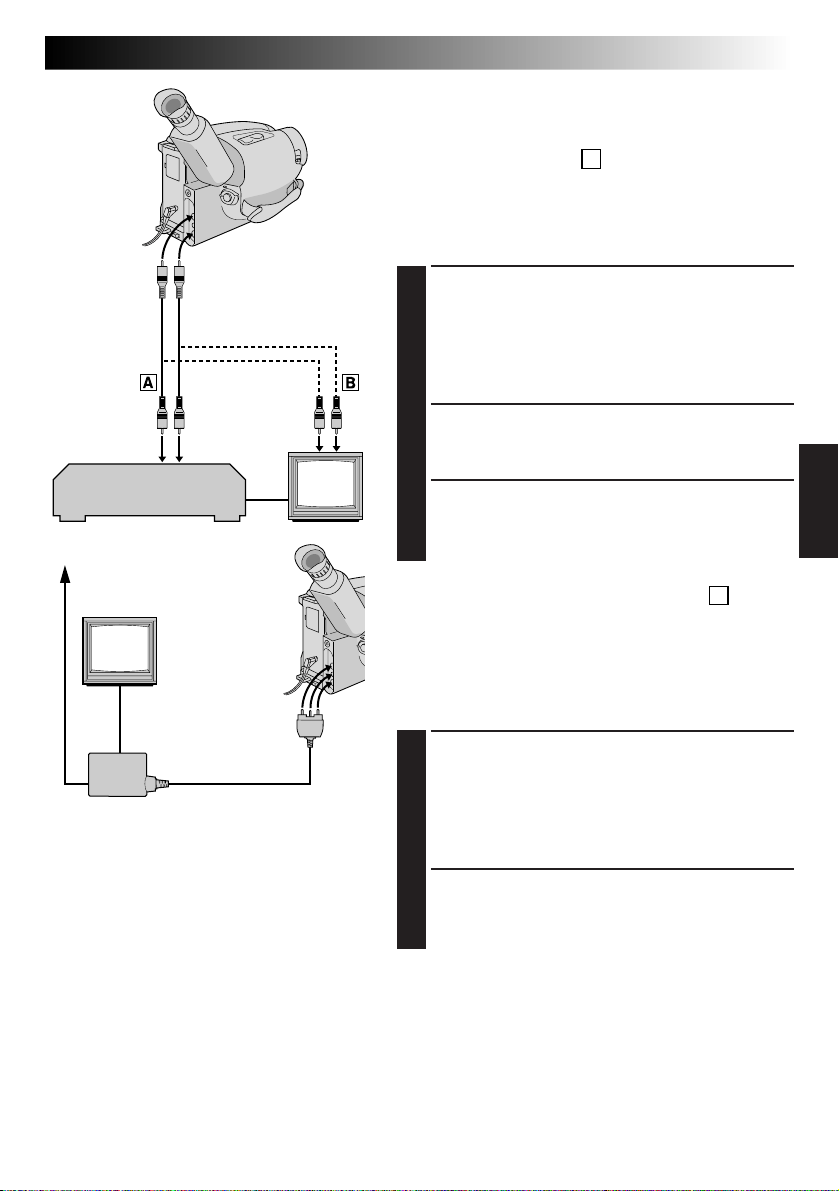
REPRODUCCION
Para conectar
los cables,
abra la
cubierta
del jack.
Cables de
audio y video
(opcionales)
VCR
Antena
Hacia los conectores
AUDIO OUT y
VIDEO OUT
Hacia los
conectores
AUDIO IN y
VIDEO IN
Conexiones básicas
Hay tres tipos de conexiones básicas. Para efectuar las
conexiones refiérase también a los manuales de
instrucción de su VCR y TV.
Conexión a un VCR
(Edición, copia y reproducción)
NOTA:
Utilice el cables suministrado de audio y video.
CONEXION DE LA
VIDEOCAMARA A UN VCR
Conecte el cables de video y audio como se muestra
1
en la ilustración a la izquierda, entre los conectores
AUDIO OUT y VIDEO OUT de la cámara de video
y los del VCR.
CONEXION DE LA ALIMENTACION
Conecte la alimentación de la cámara de video del
2
VCR y del TV.
SELECCION DEL MODO
Ajuste el VCR en el modo de entrada AUX y ajuste
3
el TV en el modo de VIDEO.
Conexión a un TV con conectores B de
entrada de A/V
(Reproducción EXCLUSIVAMENTE)
ES 37
A
Hacia los conectores
AUDIO OUT, VIDEO
OUT y RF DC OUT
RF unit RF-V5U
(opcional)
NOTAS:
●
Se recomienda utilizar el adaptador/
cargador de alimentación de CA en lugar de
la batería.
●
Para monitorizar la imagen y el sonido
provenientes de una cámara de video sin
insertar un cassette, coloque el conmutador
de alimentación de la cámara de video en
CAMERA. A continuación, coloque su TV en
el modo apropiado de entrada.
●
Si usted posee un TV o altavoces que no
están especialmente blindados, no coloque
los altavoces junto al TV ya que producirá
interferencia en la imagen reproducida por
la cámara de video.
NOTA:
Utilice el cables suministrado de audio y video.
CONEXION DE LA
VIDEOCAMARA AL TV
Conecte el cables de audio y video, como se
1
muestra en la ilustración a la izquierda, entre los
conectores AUDIO OUT y VIDEO OUT de la
cámara de video y los del TV.
SELECCION DEL MODO
Ajuste el TV en el modo de VIDEO o AV (como se
2
especifica en las instrucciones del mismo).
Conexión a un TV SIN conectores de
entrada de A/V
(reproducción EXCLUSIVAMENTE)
NOTA:
Utilice la unidad opcional RF-V5U.
* Refiérase al manual de instrucción del RF-V5U para el
procedimiento de conexión.
Page 96

38 ES
PLAY/PAUSE
REW
Conmutador de alimentación
Indicador del modo de grabación
SP
4
M–0:23:45
Contador de cinta
FF
STOP
Indicador de
transporte de cinta
4
: Reproducción
3
: Avance rápido/
Búsqueda hacia
adelante
2
: Rebobinado/
Búsqueda hacia
atrás
6 : Reproducción de
imagen fija
REPRODUCCION
Reproducción básica
COLOCACION DE UN CASSETTE
Deslice EJECT para abrir el portacassette, luego
1
inserte el cassette con la etiqueta apuntando hacia
afuera. Presione PUSH para asegurarse de que el
portacassette está cerrado y bloqueado.
SELECCION DEL MODO
Coloque el conmutador de alimentación en “PLAY”.
2
Se encenderá el indicador de alimentación.
REPRODUCCION
Presione PLAY/PAUSE. La imagen reproducida
3
aparece.
PARADA DE REPRODUCCION
Presione STOP.
4
Rebobine o avance rápidamente la cinta
Con el modo de parada activado, presione REW para
rebobinar o FF para avanzar rápidamente la cinta.
NOTA:
La cámara de video se desconecta automáticamente
después de transcurridos 5 minutos aproximadamente
con el modo de parada activado. Para activarla otra vez,
coloque el conmutador de alimentación en “POWER
OFF” y a continuación en “PLAY”.
Page 97

REPRODUCCION
Funciones
AT
ES 39
Seguimiento
Esta función puede ser empleada para eliminar las barras
de ruido que aparecen en la pantalla durante la
reproducción. El ajuste inicial es seguimiento
automático. El seguimiento manual también está
disponible.
ACTIVACION DEL SEGUIMIENTO
MANUAL
Presione el disco de avance MENU con el modo de
1
reproducción activado. Continúe girandolo hasta
que desaparezcan las barras de ruido.
•Para volver al seguimiento automático presione el
disco de avance MENU. “AT” destella. Cuando
termina el seguimiento automático, la indicación
desaparece.
Disco de
avance MENU
NOTAS:
●
Cuando aparecen barras de ruido durante la
reproducción, la cámara de video ingresa en el modo
de seguimiento automático y aparece indicado “AT”.
●
El seguimiento manual puede no funcionar con cintas
grabadas en otros VCR o cámaras de video.
Page 98

40 ES
STOP
COUNTER R/M
PLAY/PAUSE
FFREW
REPRODUCCION
FUNCION: Reproducción de imagen fija
PROPOSITO: Para hacer una pausa durante la
OPERACION: 1) Presione PLAY/PAUSE durante la
NOTA:
FUNCION: Búsqueda rápida
PROPOSITO: Para permitirle la búsqueda a alta
OPERACION:
NOTA:
FUNCION: Función de memoria de contador
PROPOSITO: Para facilitar la localización de
OPERACION: 1) Presione COUNTER R/M y
NOTAS: ●
reproducción.
reproducción.
2) Para reanudar la reproducción
normal, presione otra vez PLAY/
PAUSE.
Aparecerán barras de interferencia y
las imágenes pueden ser monocromáticas durante la reproducción de
imagen fija. Esto es normal.
velocidad en cualquier sentido.
Búsqueda hacia adelante
1) Presione FF durante la
reproducción.
Búsqueda hacia atrás
1) Presione REW durante la
reproducción.
Aparecerán barras de interferencia y
las imágenes pueden ser monocromáticas durante la búsqueda rápida.
Esto es normal.
segmentos específicos de la cinta.
manténgalo presionado durante
más de un segundo. El contador se
reposicionará a “0:00:00”.
2) Presione COUNTER R/M durante
menos de un segundo. Aparecerá
“M”.
3) Después de grabar o reproducir,
presione STOP y después REW. La
cinta para automáticamente en o
cerca de 0:00:00.
4) Para iniciar la reproducción
presione PLAY/PAUSE.
La memoria del contador funciona
en los modos de avance rápido y
de rebobinado.
●
Para desactivar la función de
memoria del contador presione
COUNTER R/M
un segundo para que “M”
desaparezca.
Funciones (cont.)
durante
menos de
Page 99

COPIA DE CINTAS
PLAY/PAUSE
ES 41
Copia de cintas
CONEXION DEL EQUIPO
Conecte la cámara de video y el VCR basándose en
1
la ilustración a la izquierda.
PREPARATIVOS PARA LA COPIA
Coloque el conmutador de alimentación de la
2
cámara de video en PLAY, conecte la alimentación
del VCR e inserte los cassettes apropiados en la
cámara de video y en el VCR.
SELECCION DEL MODO DEL VCR
Active los modos AUX y pausa de grabación del
3
VCR.
Conmutador
de alimentación
Para conectar los
cables, abra la
cubierta del jack.
Cables de
audio y video
(opcionales)
Hacia los
conectores
AUDIO OUT y
VIDEO OUT
Hacia los
conectores
AUDIO IN y
VIDEO IN
VCR
(platina de grabación)
BUSQUEDA DEL PUNTO PARA
EDICION POR INSERCION
Active el modo de reproducción de la cámara de
4
video para encontrar el punto inmediato previo al
punto de edición por inserción. Una vez que lo
encuentra, presione PAUSE en la cámara de video.
INICIO DE LA EDICION
Presione PLAY en la cámara de video y active el
5
modo de grabación del VCR.
PARADA TEMPORRARIAL DE
EDICION
Active el modo de pausa de grabación del VCR y
6
presione PAUSE en la cámara de video.
EDICION DE SEGMENTOS
ADICIONALES
Repita los pasos de 4 a 6 para edición adicional y al
7
terminar detenga el VCR y la cámara de video.
Page 100

42 ES
2
1
3
4
5
6
1
7
%
^
2
@
4
6
&
La unidad de control remoto con funciones completas puede operar a distancia esta cámara de video así
como también las operaciones básicas (PLAY, STOP, PAUSE, FF, y REW) de su grabadora de video. El control
remoto hace posible funciones adicionales de grabación.
USO DEL CONTROL REMOTO
A
a
2
1
RM-V705U
(suministrado)
Botones Con el interruptor de alimentación de la Con el interruptor de alimentación de la
1
Ventanilla de transmisión
del rayo infrarrojo
2 ZOOM (T/W) Alejamiento/acercamiento de la imagen
3 PLAY — Inicio de reproducción (Z p. 38)
4 STOP — Parada (Z p. 38)
5 REW
6 INSERT — Edición por inserción (Z p. 48)
7 START/STOP Funciona de la misma forma que el botón de inicio/parada de grabación de una cámara
8 INT. TIME Disparador automático/lapso de tiempo
9 REC TIME Animación/tiempo transcurrido (Z p. 43) —
0 PAUSE — Pausa (Z p. 40)
! FF Retoma (Avance) (Z p. 19) Avance/búsqueda progresiva (Z p. 38, 40)
@ A. DUB — Copia de audio (Z p. 49)
# PAUSE IN (Conector de
entrada de pausa)
$ MBR SET — Z p. 44
% VISS Marcación de código índice (Z p. 43) —
^ VCR CTL — Z p. 44
& R. A. EDIT — Z p. 46
# — & : RM-V700U exclusivamente.
B
2
3
3
1
Orificio
de bloqueo
#
7
8
$
9
8
9
0
!
5
!
0
3
@
cámara de video colocado en “CAMERA”. cámara de video colocado en “PLAY”.
Transmite el rayo de señales.
Z p. 18)
(
Retoma (Rebobinado)/revisión rápida
de video.
Z p. 43)
(
1
1
C
2
1
RM-V700U
(opcional)
3
1
Orejeta de
liberación
—
Inserción de la pila
EXTRACCION DEL
PORTAPILA
TipoA: Extráigalo insertando un objeto
1
2
3
Funciones
(Z p. 19)
TipoB: Extráigalo deslizando el orificio
TipoC: Presione para soltar la orejeta y
INSERCION DE LA PILA
Coloque la pila de litio (CR2025)*, con su
lado (+) hacia arriba, en el portapila.
REEMPLAZO DEL
PORTAPILA
Vuelva a colocar el portapila en la
dirección de la flecha hasta que se trabe
en su sitio.
*Lea “Precauciones sobre la pila de litio”
puntiagudo en la ranura a.
de bloqueo.
extráigalo.
en la página 2.
Rebobinado/búsqueda reversible (Z p. 38, 40)
Z p. 45
—
—
 Loading...