

Page 1
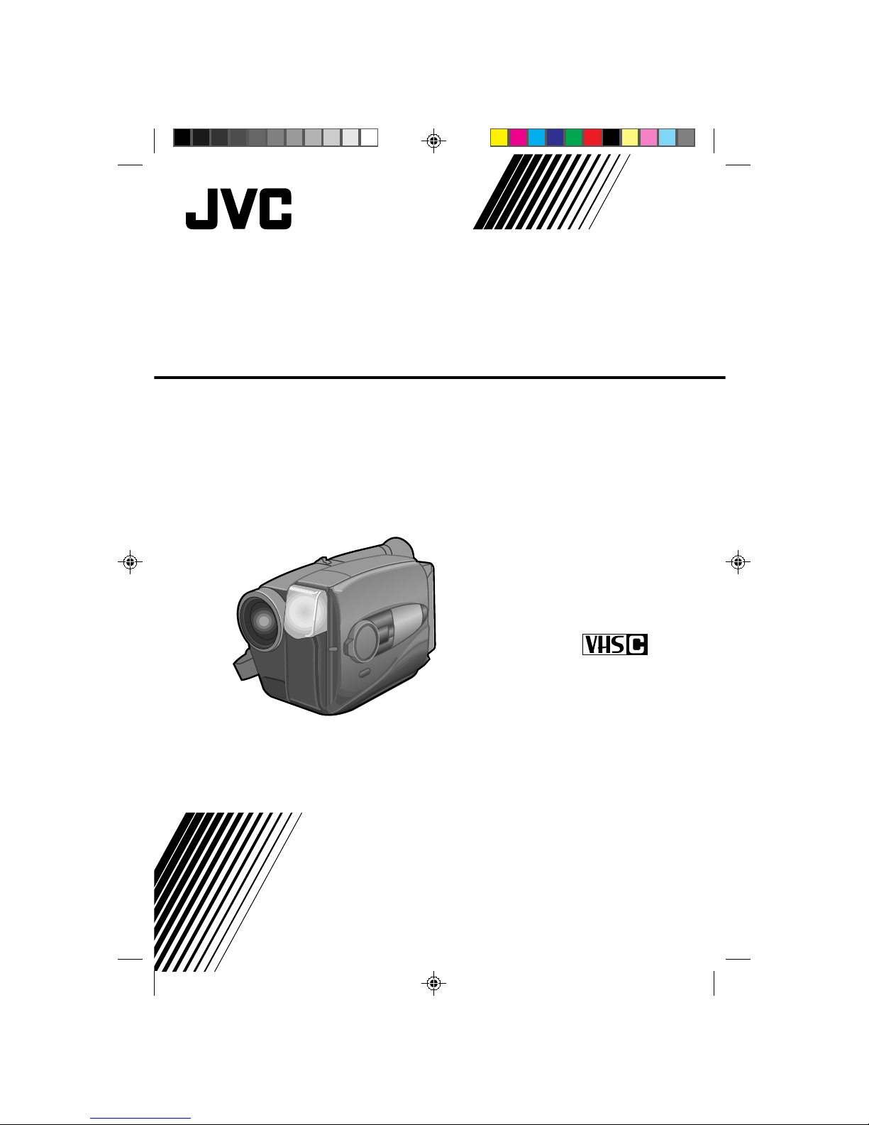
GR-AX910
YU30052-589
Compact VHS
INSTRUCTIONS
MANUEL D'INSTRUCTIONS
COMP ACT VHS CAMCORDER
CAMESCOPE COMPACT VHS
Page 2
2
WARNING:
TO PREVENT FIRE OR SHOCK
HAZARD, DO NOT EXPOSE
THIS UNIT TO RAIN OR
MOISTURE.
Warning on lithium battery
The battery used in this device may present a fire or
chemical burn hazard if mistreated. Do not recharge,
disassemble, heat above 100°C (212°F) or incinerate.
Replace the battery with Panasonic (Matsushita
Electric), Sanyo or Maxell CR2025; use of another
battery may present a risk of fire or explosion.
n Dispose of used battery promptly.
n Keep away from children.
n Do not disassemble and do not dispose of in fire.
NOTES:
●
The rating plate (serial number plate) and safety
caution are on the bottom and/or the back of the
main unit.
●
The rating plate (serial number plate) of the AC
Power Adapter/Charger is on its bottom.
This Class B digital apparatus meets all requirements of
the Canadian Interference – Causing Equipment
Regulations.
Cet appareil numérique de la classe B respecte toutes
les exigences du Règlement sur le matériel brouilleur
de Canada.
This camcorder is designed to be used with NTSC-type
color television signals. It cannot be used for playback
with a television of a different standard. However, live
recording and viewfinder playback are possible
anywhere. Use the BN-V11U/V12U/V22U/V25U
battery packs and, to recharge them, the provided
multi-voltage AC Power Adapter/Charger. (An
appropriate conversion adapter may be necessary to
accommodate different designs of AC outlets in
different countries.)
ATTENTION:
The product that you have purchased is powered by a
rechargeable battery. The battery is recyclable. At the
end of its useful life, under various state and local
laws, it may be illegal to dispose of this battery into the
municipal waste stream. Check with your local solid
waste officials for details in your area for recycling
options or proper disposal.
Dear Customer,
Thank you for purchasing the JVC Compact VHS
camcorder. Before use, please read the safety
information and precautions contained in the following
pages to ensure safe use of your new camcorder.
Using This Instruction Manual
• All major sections and subsections are listed in the Table
Of Contents (
Z pg. 7).
• Notes appear after most subsections. Be sure to read
these as well.
• Basic and advanced features/operation are separated for
easier reference.
It is recommended that you . . .
..... refer to the Index (
Z pgs. 49 – 52) and
familiarize yourself with button locations, etc. before
use.
..... read thoroughly the Safety Precautions and Safety
Instructions that follow. They contain extremely
important information regarding the safe use of your
new camcorder.
You are recommended to carefully read the cautions
on pages 53 and 54 before use.
SAFETY
PRECAUTIONS
The AA-V11U AC Power Adapter/Charger should be
used with:
AC 120 V`, 60 Hz in the USA and Canada,
AC 110 – 240 V`, 50/60 Hz in other countries.
CAUTION (applies to the AA-V11U)
TO PREVENT ELECTRIC SHOCK MATCH WIDE
BLADE OF PLUG TO WIDE SLOT, FULLY INSERT.
ATTENTION (s'applique à l'AA-V11U)
POUR ÉVITER LES CHOCS ÉLECTRIQUES,
INTRODUIRE LA LAME LA PLUS LARGE DE LA
FICHE DANS LA BORNE CORRESPONDANTE
DE LA PRISE ET POUSSER JUSQU'AU FOND.
CAUTION
RISK OF ELECTRIC SHOCK
DO NOT OPEN
CAUTION: TO REDUCE THE RISK OF ELECTRIC SHOCK.
DO NOT REMOVE COVER (OR BACK).
NO USER-SERVICEABLE PARTS INSIDE.
REFER SERVICING TO QUALIFIED SERVICE PERSONNEL.
The lightning flash with arrowhead symbol, within an
equilateral triangle, is intended to alert the user to the
presence of uninsulated "dangerous voltage" within the
product's enclosure that may be of sufficient magnitude
to constitute a risk of electric shock to persons.
The exclamation point within an equilateral triangle is
intended to alert the user to the presence of important
operating and maintenance (servicing) instructions in
the literature accompanying the appliance.
Page 3
3
5. Ventilation
Slots and openings in the cabinet are provided for
ventilation. To ensure reliable operation of the product and
to protect it from overheating, these openings must not be
blocked or covered.
• Do not block the openings by placing the product on a
bed, sofa, rug or other similar surface.
• Do not place the product in a built-in installation such as
a bookcase or rack unless proper ventilation is provided
or the manufacturer’s instructions have been adhered to.
6. Wall or Ceiling Mounting
The product should be mounted to a wall or ceiling only as
recommended by the manufacturer.
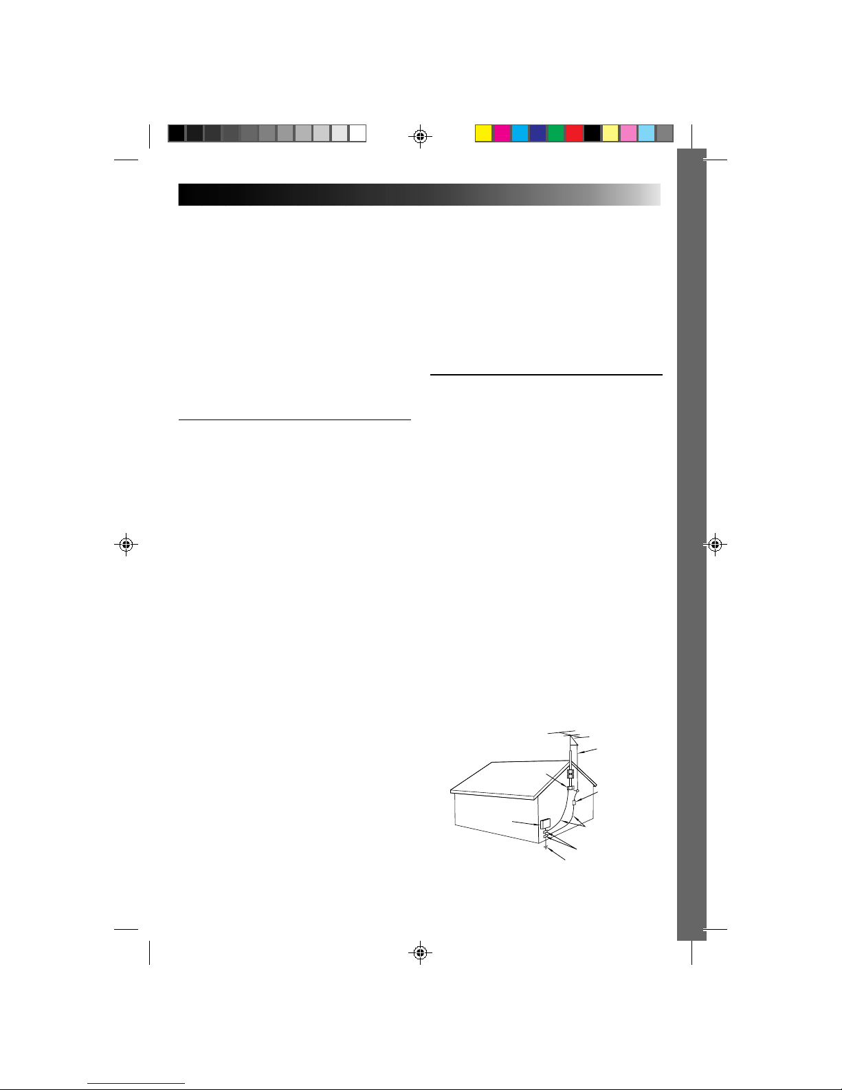
ANTENNA INSTALLATION
INSTRUCTIONS
1. Outdoor Antenna Grounding
If an outside antenna or cable system is connected to the
product, be sure the antenna or cable system is grounded
so as to provide some protection against voltage surges and
built-up static charges. Article 810 of the National Electrical
Code, ANSI/NFPA 70, provides information with regard to
proper grounding of the mast and supporting structure,
grounding of the lead-in wire to an antenna discharge unit,
size of grounding conductors, location of antenna
discharge unit, connection to grounding electrodes, and
requirements for the grounding electrode.
2. Lightning
For added protection for this product during a lightning
storm, or when it is left unattended and unused for long
periods of time, unplug it from the wall outlet and
disconnect the antenna or cable system. This will prevent
damage to the product due to lightning and power-line
surges.
3. Power Lines
An outside antenna system should not be located in the
vicinity of overhead power lines or other electric light or
power circuits, or where it can fall into such power lines or
circuits. When installing an outside antenna system,
extreme care should be taken to keep from touching such
power lines or circuits as contact with them might be fatal.
IMPORTANT PRODUCT
SAFETY INSTRUCTIONS
Electrical energy can perform many useful functions. But
improper use can result in potential electrical shock or fire
hazards. This product has been engineered and
manufactured to assure your personal safety. In order not to
defeat the built-in safeguards, observe the following basic
rules for its installation, use and servicing.
ATTENTION:
Follow and obey all warnings and instructions marked on
your product and its operating instructions. For your safety,
please read all the safety and operating instructions before
you operate this product and keep this manual for future
reference.
INSTALLATION
1. Grounding or Polarization
(A) Your product may be equipped with a polarized
alternating-current line plug (a plug having one blade
wider than the other). This plug will fit into the power
outlet only one way. This is a safety feature.
If you are unable to insert the plug fully into the outlet,
try reversing the plug. If the plug should still fail to fit,
contact your electrician to replace your obsolete outlet.
Do not defeat the safety purpose of the polarized plug.
(B) Your product may be equipped with a 3-wire
grounding-type plug, a plug having a third (grounding)
pin. This plug will only fit into a grounding-type power
outlet. This is a safety feature.
If you are unable to insert the plug into the outlet,
contact your electrician to replace your obsolete outlet.
Do not defeat the safety purpose of the grounding-type
plug.
2. Power Sources
Operate your product only from the type of power source
indicated on the marking label. If you are not sure of the
type of power supply to your home, consult your product
dealer or local power company. If your product is intended
to operate from battery power, or other sources, refer to the
operating instructions.
3. Overloading
Do not overload wall outlets, extension cords, or integral
convenience receptacles as this can result in a risk of fire or
electric shock.
4. Power Cord Protection
Power supply cords should be routed so that they are not
likely to be walked on or pinched by items placed upon or
against them, paying particular attention to cords at plugs,
convenience receptacles, and the point where they exit
from the product.
ANTENNA
LEAD IN WIRE
ANTENNA
DISCHARGE UNIT
(NEC SECTION
810-20)
GROUNDING
CONDUCTORS
(NEC SECTION 810-21)
GROUND CLAMPS
POWER SERVICE GROUNDING ELECTRODE SYSTEM
(NEC ART 250. PART H)
NEC – NATIONAL ELECTRICAL CODE
ELECTRIC SERVICE
EQUIPMENT
EXAMPLE OF ANTENNA GROUNDING AS PER
NATIONAL ELECTRICAL CODE, ANSI/NFPA 70
GROUND CLAMP
Page 4

4
USE
1. Accessories
To avoid personal injury:
• Do not place this product on an unstable cart, stand,
tripod, bracket or table. It may fall, causing serious injury
to a child or adult, and serious damage to the product.
• Use only with a cart, stand, tripod, bracket, or table
recommended by the manufacturer or sold with the
product.
• Use a mounting accessory recommended by the
manufacturer and follow the manufacturer’s instructions
for any mounting of the product.
• Do not try to roll a cart with small casters across
thresholds or deep-pile carpets.
2. Product and Cart Combination
A product and cart combination should be moved with
care. Quick stops, excessive force, and uneven surfaces
may cause the product and cart combination to overturn.
3. Water and Moisture
Do not use this product near
water—for example, near a bath
tub, wash bowl, kitchen sink or
laundry tub, in a wet basement, or
near a swimming pool and the
like.
4. Object and Liquid Entry
Never push objects of any kind into this product through
openings as they may touch dangerous voltage points or
short-out parts that could result in a fire or electric shock.
Never spill liquid of any kind on the product.
5. Attachments
Do not use attachments not recommended by the
manufacturer of this product as they may cause hazards.
6. Cleaning
Unplug this product from the wall outlet before cleaning.
Do not use liquid cleaners or aerosol cleaners. Use a damp
cloth for cleaning.
7. Heat
The product should be situated away from heat sources
such as radiators, heat registers, stoves, or other products
(including amplifiers) that produce heat.
SERVICING
1. Servicing
If your product is not operating correctly or exhibits a
marked change in performance and you are unable to
restore normal operation by following the detailed
procedure in its operating instructions, do not attempt to
service it yourself as opening or removing covers may
expose you to dangerous voltage or other hazards. Refer all
servicing to qualified service personnel.
2. Damage Requiring Service
Unplug this product from the wall outlet and refer servicing
to qualified service personnel under the following
conditions:
a. When the power supply cord or plug is damaged.
b. If liquid has been spilled, or objects have fallen into the
product.
c. If the product has been exposed to rain or water.
d. If the product does not operate normally by following
the operating instructions. Adjust only those controls that
are covered by the operating instructions as an improper
adjustment of other controls may result in damage and
will often require extensive work by a qualified
technician to restore the product to its normal operation.
e. If the product has been dropped or damaged in any way.
f. When the product exhibits a distinct change in
performance—this indicates a need for service.
3. Replacement Parts
When replacement parts are required, be sure the service
technician has used replacement parts specified by the
manufacturer or have the same characteristics as the
original part. Unauthorized substitutions may result in fire,
electric shock or other hazards.
4. Safety Check
Upon completion of any service or repairs to this product,
ask the service technician to perform safety checks to
determine that the product is in safe operating condition.
PORTABLE CART WARNING
(Symbol provided by RETAC)
Page 5
5
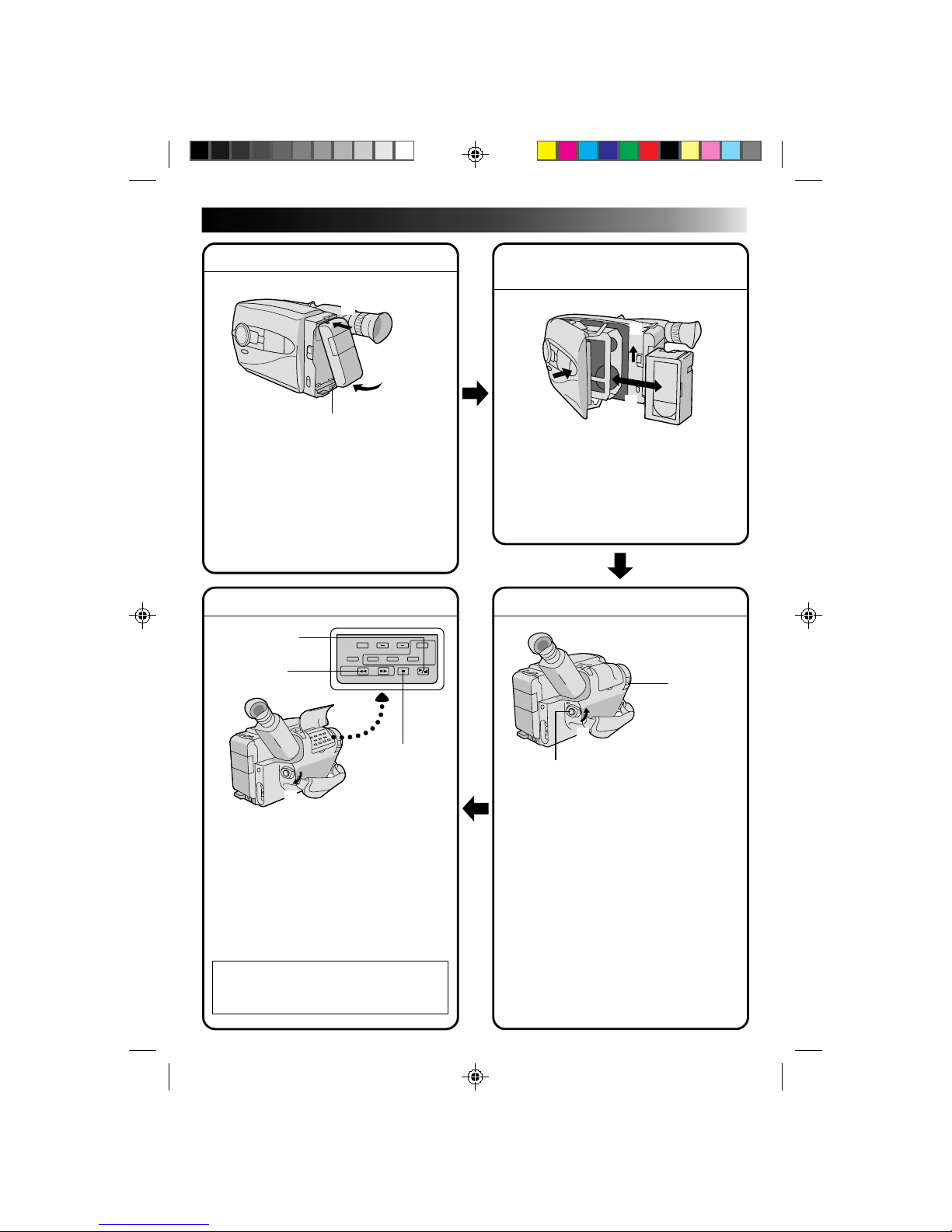
QUICK OPERATION GUIDE
SUPPLY POWER
Using the battery pack
1
Hook-on the battery pack's top end to the
camcorder. (Charging procedure, Z P. 8)
2 Push in the battery pack until it locks into
place.
To remove the battery pack
Slide BATT. RELEASE and pull out the battery
pack.
PLAYBACK
1 Set the power switch to “PLAY”.
2 Press REW.
— The tape will automatically stop at the
beginning of the tape.
3 Press PLAY/PAUSE.
— Playback starts and the playback picture
appears in the viewfinder.
•To stop playback, press STOP.
(For more details, Z P. 38.)
n
Or simply play back the tape on a VHS
VCR using the Cassette Adapter
(VHS Playpak). Z P. 36
SHOOTING
1 Slide the LENS COVER open/close knob to
open the lens cover.
2 Set the power switch to “CAMERA”.
— The power indicator will light and an
image will appear in the viewfinder.
3 Press RECORDING START/STOP.
— Recording starts.
•To stop recording temporarily, momentarily
press the Recording Start/Stop button once
again.
(For more details, Z P. 16)
2
Push in.
1
Hook on.
BATT. RELEASE
3
1
PUSH
Insert.
EJECT
2
2
REW
1
Set to “PLAY”
1
LENS COVER
open/close knob
3
Recording Start/Stop button
2
Set to “CAMERA”
INSERTING A VIDEO
CASSETTE
1 Slide EJECT.
2 Insert a video cassette.
3 Press PUSH.
(For more details, Z P. 13)
STOP
3
PLAY/PAUSE
Page 6
6
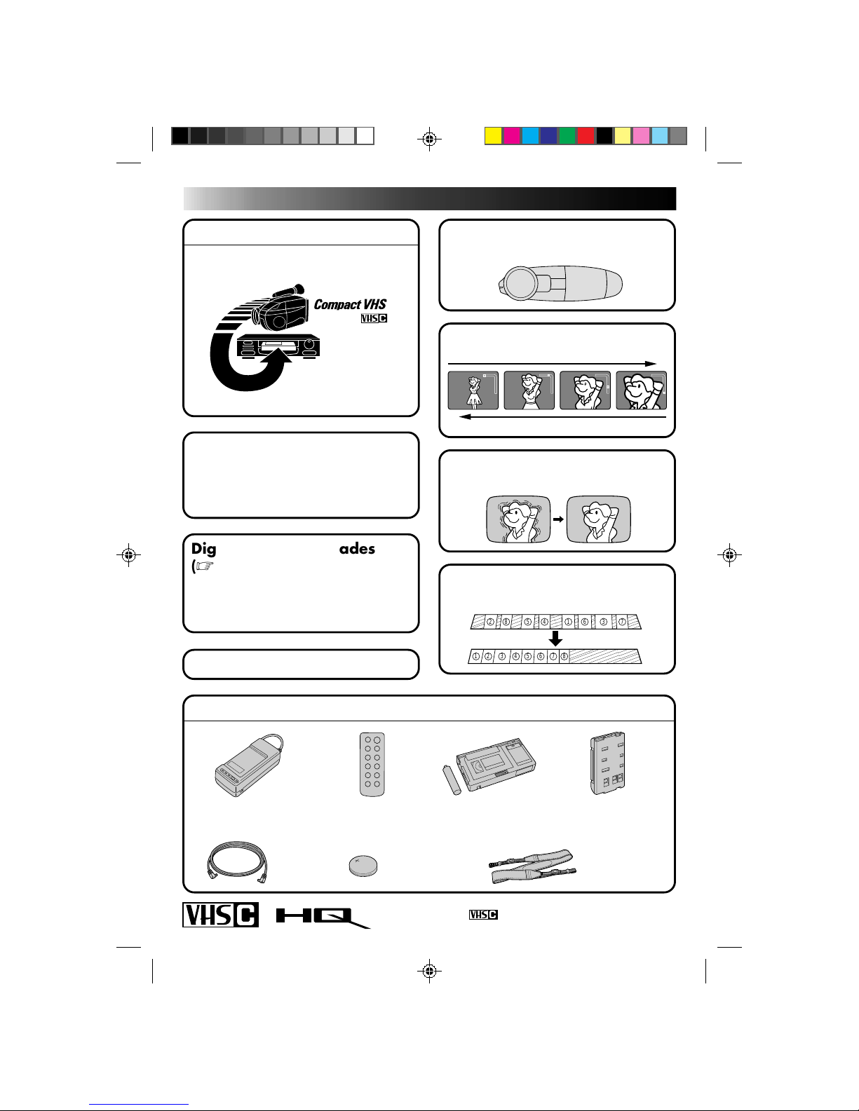
MAJOR FEATURES
REMEMBER
The Logical Choice
The only compact video
cassettes that can be
used with your VHS VCR*
*
with VHS Playpak
Program AE with Special
Effects (
Z pg. 26)
n Cinema n Sepia n Twilight n Sports
n High Speed (1/2000 sec.) Shutter
Multi Function Control
(
Z pg. 22 – 35)
Random Assemble Editing
(
Z pg. 40 – 43)
PROVIDED ACCESSORIES
Cassettes marked can be used with this camcorder.
W
T
W
T
W
T
W
T
Zoom-in
Zoom-out
882
2
554411663
3
7
7
Digital Wipes and Fades
(
Z pg. 28)
● Black Fader ● Blue Fader
● Mosaic Fader ● Shutter Wipe
● Slide Wipe
Built-In Auto Light (Z pg.19)
Digital Hyper Zoom (Z pg. 17)
Digital Image Stabilizer
(
Z pg. 22)
•AC Power Adapter/
Charger AA-V11U
•Battery Pack
BN-V11U
•Cassette Adapter
(VHS PlayPak)
C-P7U
•Remote Control
Unit RM-V705U
•Lithium Battery
CR2025
•DC Cord •Shoulder Strap
Page 7
7
CONTENTS
GETTING STARTED
8
Power ................................................................................................ 8
Clock (Lithium) Battery Removal/Insertion................................................... 10
Viewfinder Adjustment .......................................................................... 10
Date/Time Setting ............................................................................... 11
Tape Length Setting .............................................................................. 12
Recording Mode Setting ......................................................................... 13
Loading/Unloading A Cassette ................................................................. 13
Grip Adjustment .................................................................................. 14
Shoulder Strap Attachment ...................................................................... 14
Tripod Mounting ..................................................................................14
Using The RM-V705U Remote Control Unit .................................................. 15
RECORDING
16
Basic Recording ................................................................................... 16
Basic Features..................................................................................... 17
Video Light ........................................................................................ 19
Advanced Features ............................................................................... 20
Date/Time Insert ................................................................................... 20
Quick Rec ............................................................................................ 21
Digital Image Stabilizer (D.I.S.) .............................................................. 22
Exposure Control .................................................................................. 22
White Balance Adjustment..................................................................... 23
Focusing ............................................................................................... 24
Program AE With Special Effects............................................................. 26
Fade/Wipe ............................................................................................ 28
Using Menu For Detailed Adjustment ..................................................... 30
Instant Titles ......................................................................................... 32
Self-Timer............................................................................................. 34
Animation ............................................................................................ 35
Time Lapse ........................................................................................... 35
PLAYBACK
36
Using The Cassette Adapter..................................................................... 36
Basic Connections .................................................................................37
Basic Playback .................................................................................... 38
Features ........................................................................................... 39
EDITING
40
Tape Dubbing ...................................................................................... 40
Random Assemble Editing [R.A.Edit]...........................................................40
Insert Editing ......................................................................................44
Audio Dubbing.....................................................................................45
USER MAINTENANCE
46
TROUBLESHOOTING
47
INDEX
49
Controls ............................................................................................49
Connectors......................................................................................... 50
Indicators .......................................................................................... 50
Other Parts ........................................................................................50
Viewfinder ........................................................................................ 51
Term s ............................................................................................... 52
CAUTIONS
53
SPECIFICATIONS
55
GETTING STARTED
RECORDING
PLAYBACK
EDITING
Page 8
8
GETTING STARTED
Power
This camcorder’s 3-way power supply system lets you
choose the most appropriate source of power.
NOTES:
●
No function is available without power supply.
●
Use only specified power supply.
●
Do not use provided power supply units with other equipment.
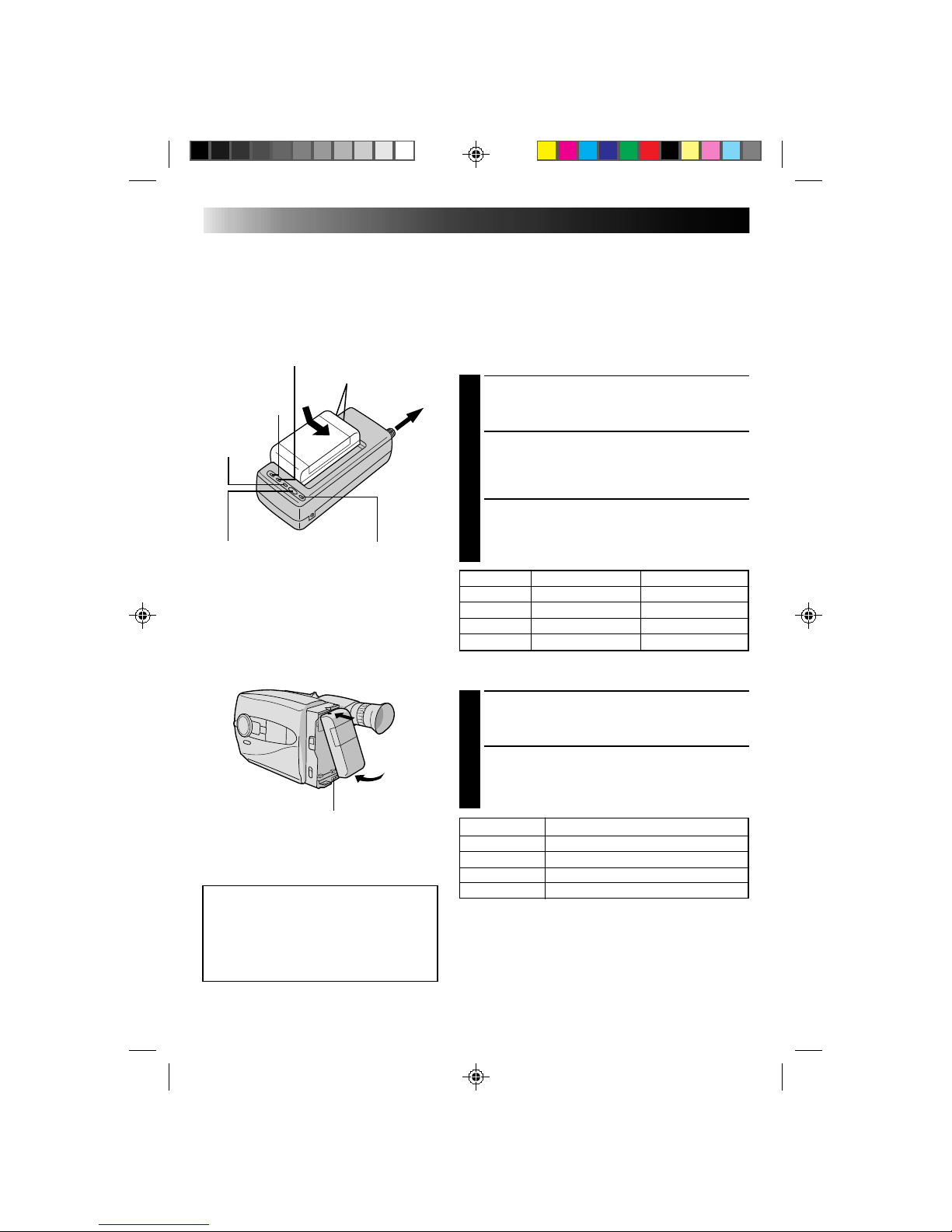
CHARGING THE BATTERY PACK
SUPPLY POWER
1
Connect the charger’s AC power cord to a wall
outlet. The power indicator lights.
ATTACH BATTERY PACK
2
Align the marks and slide the battery pack in the
direction of the arrow until it locks in place.
The CHG. indicator lights.
DETACH BATTERY PACK
3
When charging is completed, the END indicator
lights. Slide the battery pack opposite the direction
of the arrow.
USING THE BATTERY PACK
ATTACH BATTERY PACK
1
Hook its top end to the camcorder and push the
battery pack in until it locks in place.
DETACH BATTERY PACK
2
Slide BATT. RELEASE and pull out the battery pack.
BATT. PACK CHARGE DISCHARGE
BN-V11U approx. 1 hr. 10 min. approx. 3 hrs. 30 min.
BN-V12U approx. 1 hr. 10 min. approx. 3 hrs. 30 min.
BN-V22U approx. 2 hrs. 10 min. approx. 7 hrs.
BN-V25U approx. 2 hrs. 40 min. approx. 10 hrs.
( ): When the Video Light is on
BATT. PACK APPROXIMATE RECORDING TIME
BN-V11U 1 hr. (35 min.)
BN-V12U 1 hr. 5 min. (40 min.)
BN-V22U 2 hrs. 15 min. (1 hr. 25 min.)
BN-V25U 3 hrs. (1 hr. 50 min.)
**REFRESH
The AC power adapter features a REFRESH function that allows
you to fully discharge the battery pack before recharging.
To discharge the battery . . .
..... attach the battery pack to the adapter as shown in the
illustration to the left. Then push REFRESH. The REFRESH
indicator lights when discharging starts, and goes out when
discharging is complete.
ATTENTION:
Before detaching the power source,
make sure that the camcorder’s power
is turned off. Failure to do so can result
in a camcorder malfunction.
REFRESH indicatorREFRESH switch
CHG. (charge) indicator
To AC outlet
Marks
END
indicator
Hook on.
Push in.
BATT. RELEASE
POWER
indicator
Page 9
9
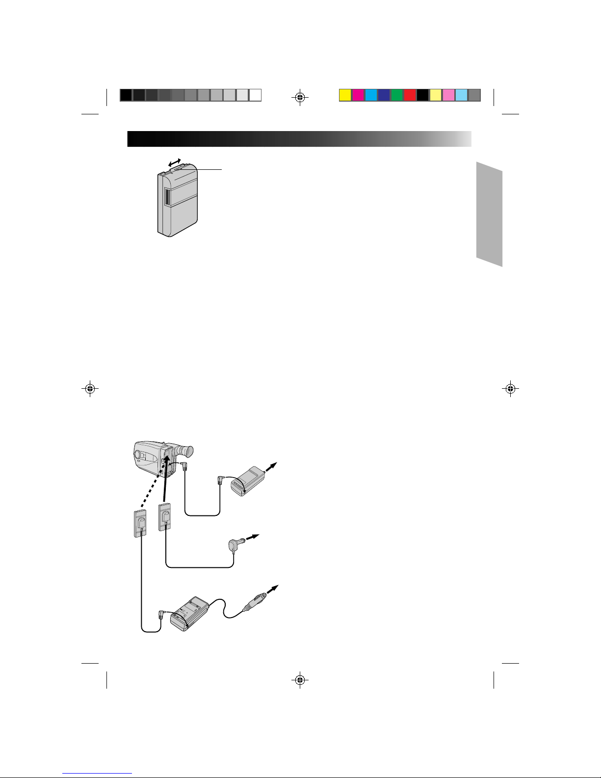
**CHARGE MARKER
A charge marker is provided on the battery pack to
help you remember whether it has been charged or
not. Two colors are provided (red and black)—you
choose which one means charged and which
means discharged.
NOTES:
●
The recording time per charge is affected by such factors as the time spent in Record/Standby mode and
the frequency of zooming. It is safer to have spare battery packs.
●
Charging times noted on page 8 are for fully discharged battey pack, and discharging times are for fully
charged battery pack.
●
Charging and discharging times vary according to the ambient temperature and the status of the battery
pack.
●
Remember to set the charge marker after charging a battery pack or after detaching a discharged one from
your camcorder.
●
Perform the REFRESH function after no less than 5 chargings.
●
High temperatures can damage the battery pack, so use only where good ventilation is available. Don’t
allow it to discharge in container, such as a bag.
●
If you stop recharging or discharging part way through, make sure to remove the battery pack before
unplugging the adapter’s AC cord.
●
Remove the battery pack from the adapter immediately after discharging.
●
To avoid interference with reception, do not use the AC Power Adapter/Charger near a radio.
●
Make sure you unplug the DC cord before charging or discharging the battery pack.
●
A blinking CHG. indicator means that the battery pack has become hot. Wait until it cools down to
continue.
●
The CHG. indicator may not light properly with a brand new battery pack, or with one that’s been stored
for an extended period. In this case, remove and reattach the battery pack and recharge it. The CHG.
indicator should light during recharging. If not, contact your nearest JVC dealer.
USING A CAR BATTERY
Use the optional Car Battery Cord or Car Battery
Charger/Adapter (connect as shown in the
illustration to the left).
NOTES:
●
When using the car battery, leave the engine
idling.
●
The optional Car Battery Charger (BH-V3U) can
also be used to charge the battery pack.
●
When using the optional Car Battery Charger or
Car Battery Cord (AP-V7U), refer to the respective
instruction booklet.
USING AC POWER
Use the AC Power Adapter (connect as shown in
the illustration to the left).
NOTE:
The supplied AC Power Adapter/Charger features
automatic voltage selection in the AC range from
110 V to 240 V.
Charge marker
AC Power
Adapter/Charger
AA-V11U (provided)
To car's
cigarette
lighter
socket
Car Battery Charger/Adapter
BH-V3U (optional)
DC cord
Car Battery Cord
AP-V7U (optional)
To AC outlet
To
DC OUT
terminal
To
DC IN
Jack
Page 10
10
GETTING STARTED (cont.)
A
Set POWER to “CAMERA”.
3
1
2
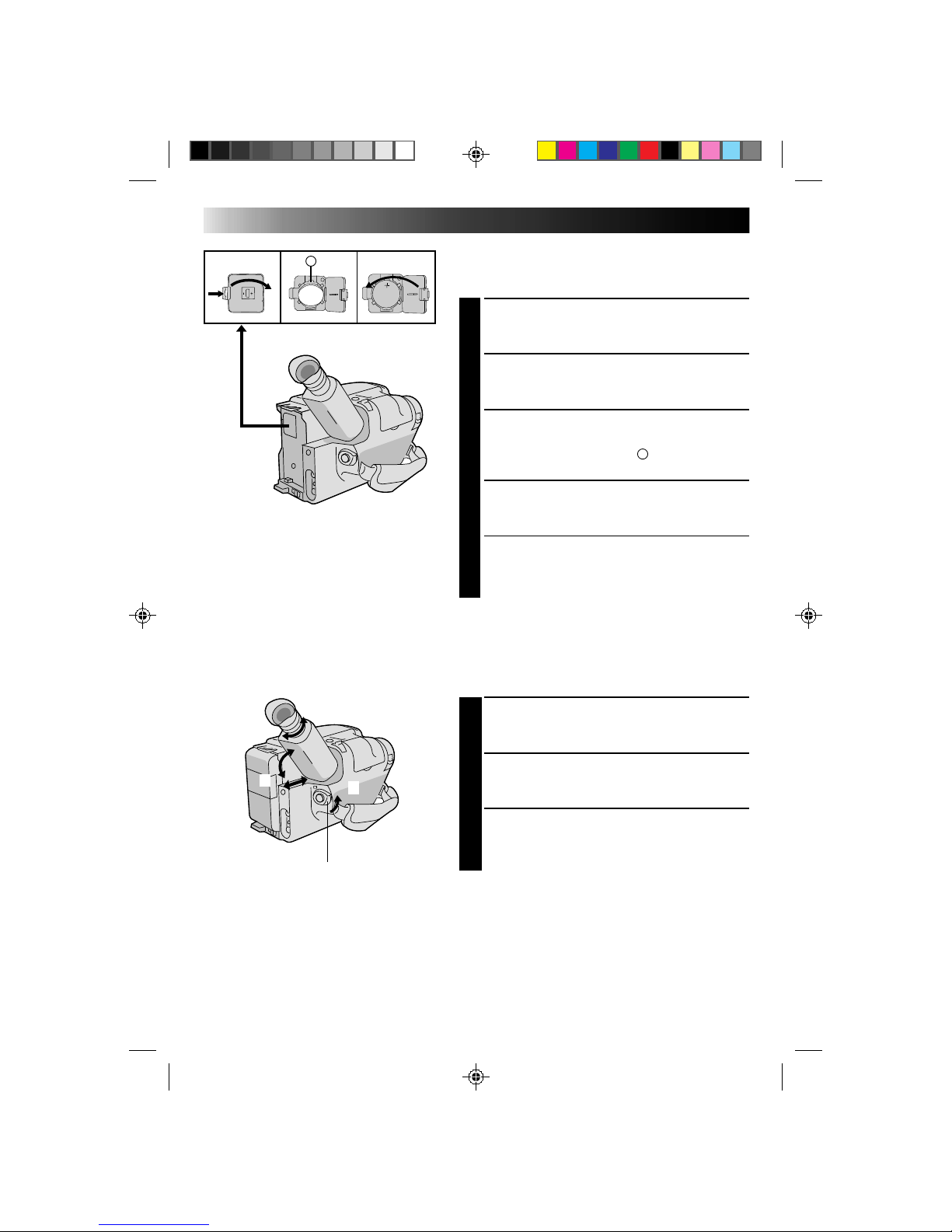
Clock (Lithium) Battery Insertion/Removal
This battery is necessary for clock operation and to
perform date/time settings.
SWITCH OFF POWER
1
Switch off the unit’s power and remove the power
supply unit.
OPEN COVER
2
Open the clock battery compartment cover while
pressing the release tab.
REMOVE BATTERY (when replacing)
3
Insert a pointed, non-metallic object between the
battery and the compartment (
A
) and pull the
battery out.
INSERT BATTERY
4
Ensuring the plus (+) side is up, insert a CR2025
lithium battery and push it in.
CLOSE COVER
5
Close the compartment cover until it clicks in place.
NOTE:
See “SAFETY PRECAUTIONS”(Z pg. 2) for information
on safe handling of lithium batteries.
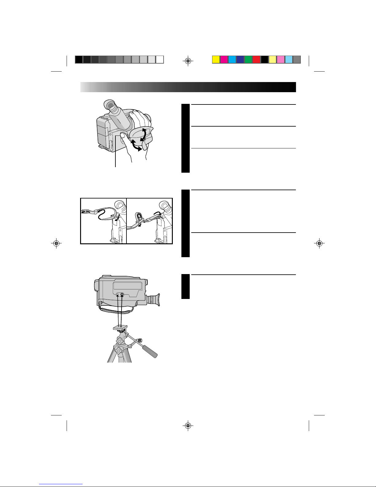
Viewfinder Adjustment
POSITION VIEWFINDER
1
Adjust the viewfinder manually for best viewability
(see illustration at left).
SELECT MODE
2
Set the power switch to CAMERA.
ADJUST DIOPTER
3
Turn the diopter adjustment control until the
indications in the viewfinder are clearly focused.
Page 11
11
Tele Macro OFF
Gain Up AGC
Color Filter NOR.
Tape Length T30
Title
Sub Menu
Set
Cancel
JAN 1.00 AM 12:00
Date/Time
–
+
FAR
NEAR
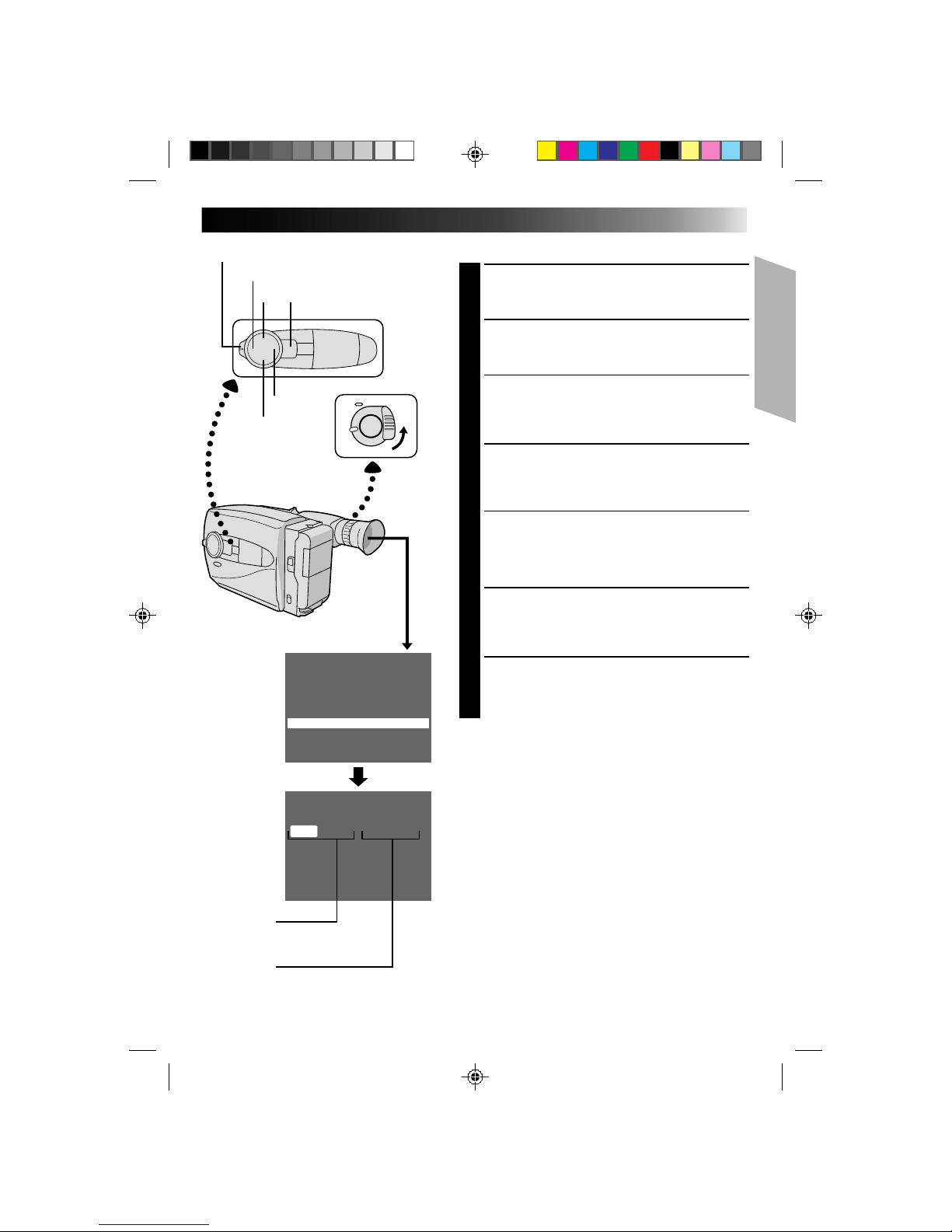
Date/Time Setting
SELECT MODE
1
Set the Power switch to “CAMERA”, and the
Shooting Mode selector to “PRESET”.
ACCESS MAIN MENU SCREEN
2
Press MENU.
SELECT FUNCTION
3
Press – to move the highlight bar down to “Date/
Time”, then press NEAR. The Set Date And Time
screen appears.
SET DATE/TIME
4
Press FAR or NEAR until the item you want to set
begins blinking, then press + or – to until the correct
setting appears.
•If you decide you want to return the date and time
to the previous settings, press FAR or NEAR to
move the highlight bar to “Cancel”, then press
MENU.
•If you’re satisfied with the settings, go on to step 5.
START CLOCK OPERATION
5
Once you’ve set the month, day, year and time,
press FAR or NEAR until “Set” begins to blink, then
press MENU. The Main Menu screen reappears.
CLOSE MAIN MENU
6
Press MENU.
NOTES:
●
To display the date and time in the viewfinder and on a
connected TV, see “Date/Time Insert” (Z pg. 20).
●
If, in step 4, you input an invalid date (FEB 30, JUN 31,
etc.) and perform step 5, “Input Error” appears blinking
at the bottom of the screen. Press +, –, FAR or NEAR to
make the day blink, and input the correct number.
Date
Month/Day/Year
Time
12-hour indication with
AM or PM
Shooting mode selector
Main Menu
Screen
Set Time and
Date Screen
MENU
Page 12
12
GETTING STARTED (cont.)
Tele Macro OFF
Gain Up AGC
Color Filter NOR.
Title
Sub Menu
Date/Time
Tape Length T40
T20
T30
T40
–
+
FAR
NEAR
Main Menu
Screen
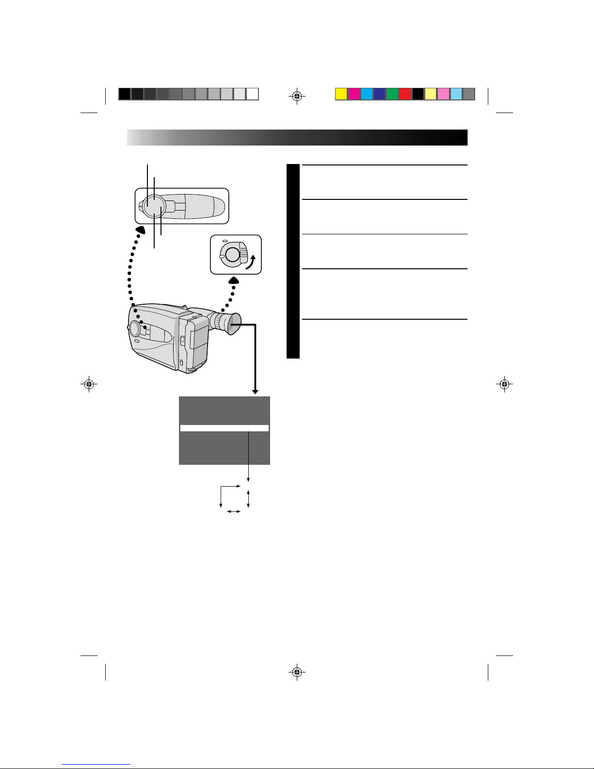
Tape Length Setting
SELECT MODE
1
Set the Power switch to “CAMERA”, and the
Shooting Mode selector to “PRESET”.
ACCESS MAIN MENU SCREEN
2
Press MENU.
SELECT FUNCTION
3
Press + or – to move the highlight bar to “Tape
Length”.
SET TAPE LENGTH
4
Press FAR or NEAR to cycle through until the correct
setting appears (depending on the tape used). T20 =
20 minutes of recording time, T30 = 30 min., and
T40 = 40 min. (when recording in SP mode).
CLOSE MAIN MENU
5
Press MENU.
NOTE:
The tape remaining time (Z pg. 16) displayed in the
viewfinder is correct only if the correct tape length has
been selected.
Page 13
13
GearErase Protection
Turn to take up
slack.
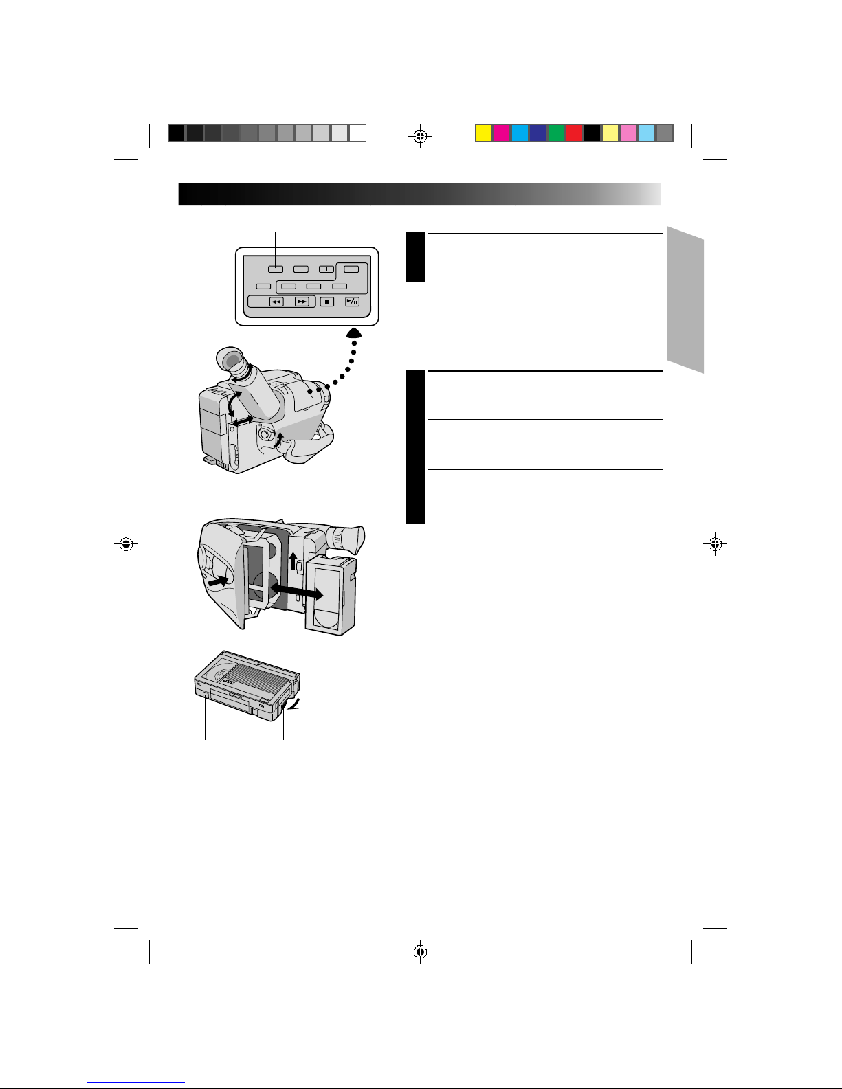
SP/EP
Recording Mode Setting
1
Pressing SP/EP alternates the setting between SP
(standard play-provides higher picture and sound
quality, better for dubbing) and EP (Extended Playmore economical, recording at 1/3 the speed of SP).
NOTE:
If the recording mode is switched during recording, the
playback picture will be blurred at the switching point.
Loading/Unloading A Cassette
OPEN CASSETTE HOLDER
1
Slide EJECT until the holder opens. Do not use force
to open.
INSERT/REMOVE CASSETTE
2
Make sure the label is facing outward.
CLOSE CASSETTE HOLDER
3
Press PUSH and make sure the holder is closed and
locked.
NOTES:
●
A cassette holder can’t be opened unless a power
supply is attached.
●
Make sure that the tape is not slack when loading the
cassette. If there is any slack, turn the gear on the
cassette in the direction of the arrow to take up the
slack.
●
Make sure the Erase Protection tab is present. If not,
cover the hole with adhesive tape. (Some cassettes
have sliding tabs – in this case, check the tab's
position.)
Page 14
14
2
3
1
2
1
GETTING STARTED (cont.)
Grip Adjustment
EXPAND LOOP
1
Separate the Velcro strip.
INSERT HAND
2
Pass your right hand through the loop and grasp the
grip.
ADJUST STRAP LENGTH
3
Adjust so your thumb and fingers can easily operate
the Recording Start/Stop button and Power Zoom
lever. Refasten the Velcro strip.
Shoulder Strap Attachment
ATTACH STRAP
1
Following the illustration at left, thread the strap
through the top of the eyelet 1, then fold it back
and thread it through the keeper 2, and then
through the buckle 3. Repeat the procedure to
attach the other end of the strap to the other eyelet,
making sure the strap isn’t twisted.
ADJUST LENGTH
2
Adjust as shown in the illustration at left 1, then
slide both keepers snug against the eyelets to
prevent slipping 2.
Tripod Mounting
ALIGN AND TIGHTEN
1
Align the screw and camera direction stud on the
tripod with the camera’s mounting socket and stud
hole. Then tighten the screw.
Recording Start/Stop button
Page 15
15
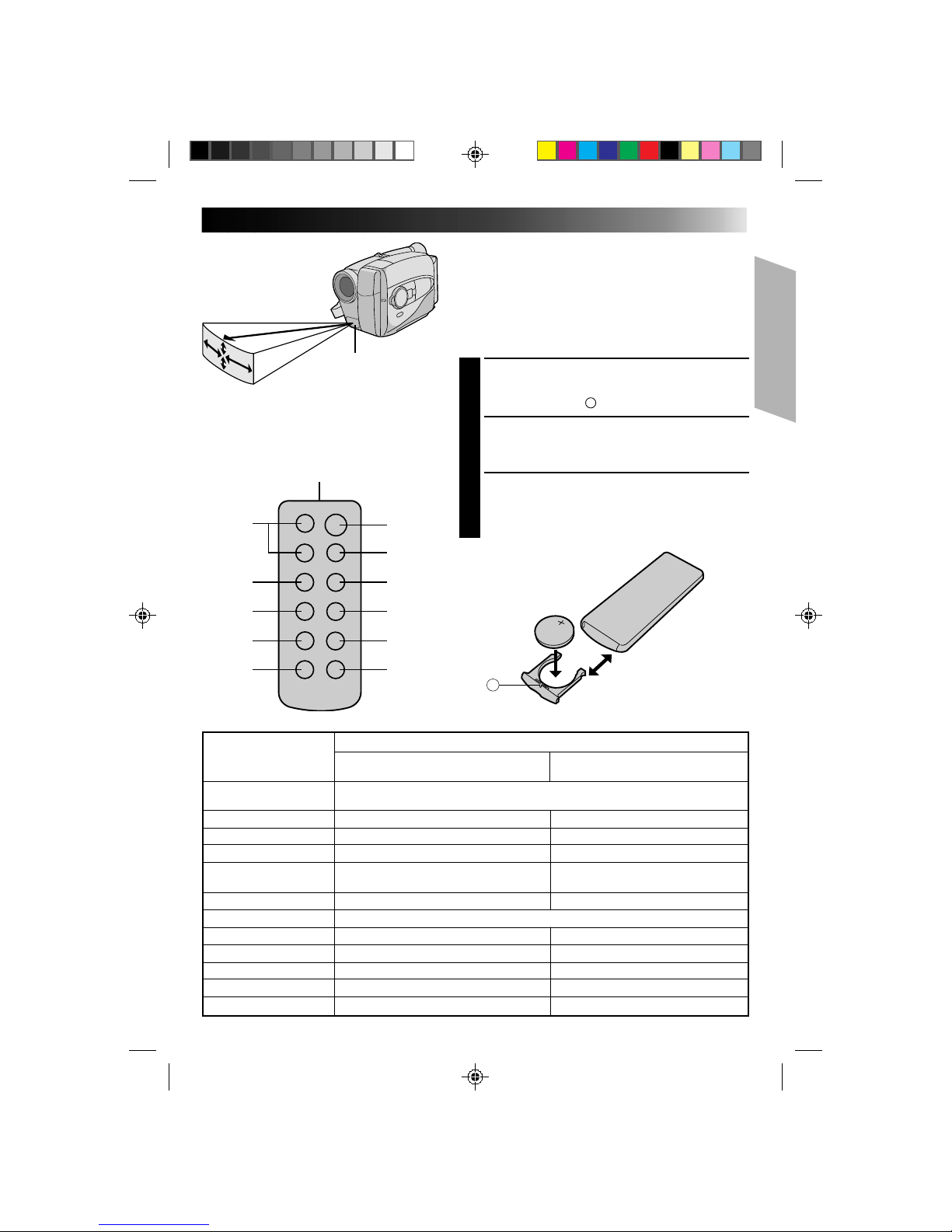
10°
5m(16.4ft)
10°
30°
30°
2
1
3
4
5
6
@
!
0
9
8
7
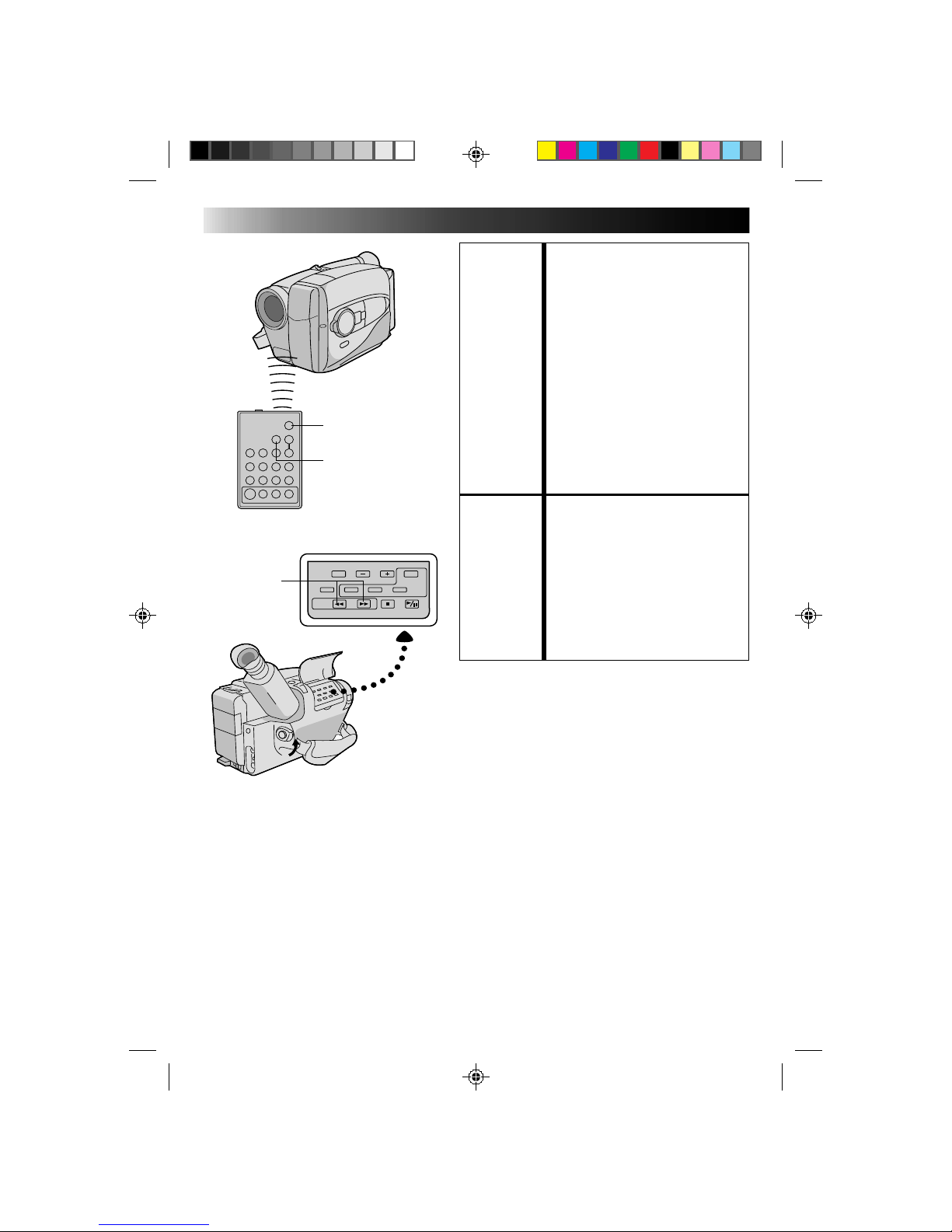
Buttons
Functions
With the camcorder’s power switch With the camcorder’s power switch set
set to “CAMERA”. to “PLAY”.
1 Infrared beam Transmits the beam signal.
transmitting window
2 ZOOM (T/W) buttons Zoom (invariable speed, Z pg. 17) —
3 PLAY button — Playback start (Z pg. 38)
4 STOP button — Stop (Z pg. 38)
5 REW button Retake (Rewind) (Z pg. 18)/ Rew/Rew Shuttle Search (Z pg. 38)
Quick Review (Z pg. 17)
6 INSERT button — Insert Editing (Z pg. 44)
7 START/STOP button Functions same as the Recording Start/Stop button of the camcorder.
8 INT. TIME button Self-Timer(Z pg. 34)/Time Lapse (Z pg. 35) —
9 REC TIME button Animation/Time lapse (Z pg. 35) —
0 PAUSE button — Pause/Play (during Pause mode) (Z pg. 38)
! FF button Retake (Forward) (Z pg. 18) FF/FF Shuttle Search (Z pg. 38)
@ A. DUB button — Audio dubbing (Z pg. 45)
Using The RM-V705U Remote Control
Unit
The Full-Function Remote Control Unit can operate this
camcorder from a distance as well as the basic
operations (PLAY, STOP, PAUSE, FF, and REW) of your
VCR. This remote control unit makes additional
recording functions possible.
PULL OUT BATTERY HOLDER
1
Pull out the battery holder by inserting a pointed
instrument into slot A.
INSERT BATTERY
2
Insert the lithium battery *(CR2025), with its plus (+)
side up, into the battery holder.
REPLACE BATTERY HOLDER
3
Insert the battery holder into the remote control unit,
and push the holder until it clicks in place.
*Read warning on lithium battery. (Z P. 2)
A
The transmitted beam may not be effective or
may cause incorrect operation when the
infrared beam sensor window is directly
exposed to sunlight or powerful lighting.
Infrared beam
effective area
Infrared beam
sensor window
Page 16
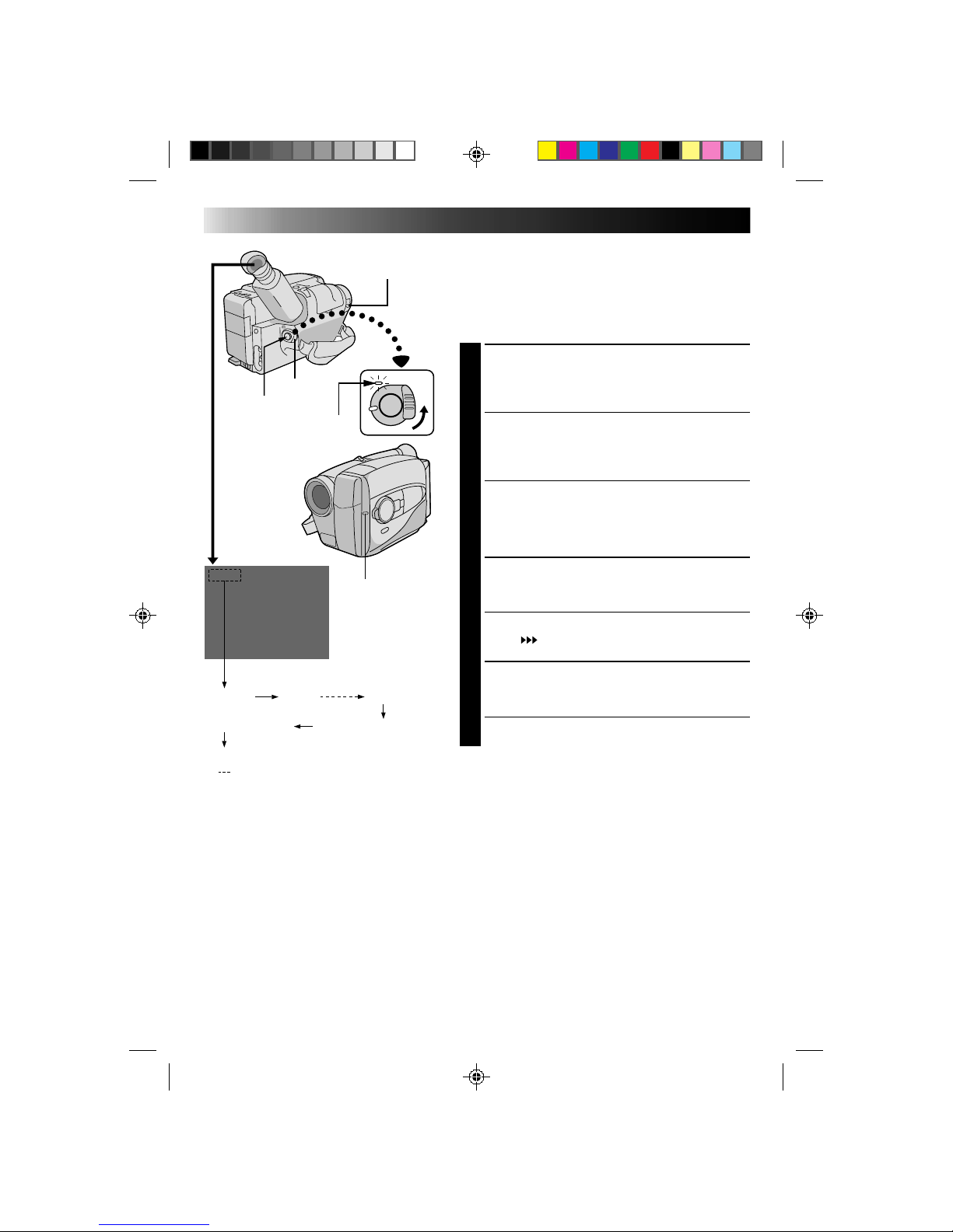
16
25min
120min 119min
3min
2min (Blinking)
1min (Blinking)
0min (Blinking)
* min.....(Now calculating)
RECORDING
Basic Recording
LENS COVER
SWITCH
NOTES:
●
A cassette holder can’t be opened unless a power supply is attached.
●
There may be a delay after you slide EJECT until the holder opens. Do not use force.
●
The tape’s remaining time is displayed in the viewfinder as shown.
●
The indicated remaining time is approximate.
●
The time required to calculate the remaining tape length, and the accuracy of the calculation, may vary
according to the type of tape used.
●
The tape remaining time displayed in the viewfinder is correct only if the correct tape length has been
selected (Z pg. 12).
●
“TAPE END” appears when the tape reaches its end, and the power goes off automatically if left in this
condition for 5 minutes. “TAPE END” also appears when a cassette whose tape is already at its end is
loaded.
●
If the Record–Standby mode continues for 5 minutes without performing Zoom or any other operations,
the camcorder’s power shuts off automatically. Set the Power switch to “POWER OFF”, and then back to
“CAMERA” to turn the camcorder on again.
●
If you’re recording on a cassette from the middle, use the Retake function (Z pg. 18) to find the end of the
last recording so you don’t erase any of it.
●
The LENS COVER warning blinks for about 8 seconds when the camcorder is turned on, when the cover is
closed.
POWER
Start/Stop
The power indicator
Tally lamp
Tape remaining time indicator
NOTE:
You should already have performed the procedures listed
below. If not, do so before continuing.
●
Power (Z pg. 8)
●
Tape Length (Z pg. 12)
●
Recording Mode Setting (Z pg. 13)
●
Grip Adjustment (Z pg. 14)
LOAD A CASSETTE
1
Slide EJECT to open the cassette holder, then insert
the cassette with the label facing out. Press PUSH to
ensure the holder is closed and locked.
ENTER RECORD–STANDBY MODE
2
Slide the LENS COVER open/close switch to open
the lens cover, then set the power switch to
“CAMERA”.
•The power indicator lights and the camcorder
enters the Record–Standby Mode.
•The scene you’re aimed at appears on the
viewfinder screen, with the word “PAUSE”
superimposed upon it.
START SHOOTING
3
Press the RECORDING START/STOP button.
•The tally lamp lights while recording is in progress,
and “
REC
” appears in the viewfinder.
•If you want to turn the tally lamp off, see page 31.
STOP RECORDING
4
Press the RECORDING START/STOP button again to
stop recording.
•The camcorder re-enters the Record-Standby
mode.
Page 17
17
W
T
W
T
W
T
W
T
W
T
Zoom-in
Zoom-out
RECORDING
Basic Features
FEATURE: Zooming
PURPOSE: To produce the zoom in/out effect, or
an instantaneous change in image
magnification.
OPERATION: 28X Hyper zoom
Digital circuitry doubles the
maximum 14x magnification offered
by optical zoom.
1) To zoom in, slide the Zoom Lever
toward “T”.
2) To zoom out, slide toward “W”.
NOTES: ●
During Hyper Zoom, the speed
increases the further you slide the
Zoom Lever.
●
Focusing may be come unstable
during Hyper Zoom. In this case,
set the zoom while in Record –
Standby, set manual focus or Focus
Lock (Z pg. 24, 25), then zoom in
or out in Record mode.
●
The Zoom Level Indicator (5) only
moves during optical zoom. Once
the indicator reaches “T”, all
magnification from that point is
through digital processing.
●
During digital image processing,
the quality of the image may suffer.
FEATURE: Quick Review
PURPOSE: To check the end of the last
recording.
OPERATION: 1) Press “
” and release quickly
during the Record–Standby mode.
•Tape is rewound for about 2
seconds and played back
automati-cally, then pauses in
Record–Standby mode for the
next shot.
NOTE:
Distortion may occur at start of
playback.
This is normal.
Zoom indicator bar
Zoom level
indicator
Power zoom lever
Page 18
18
RECORDING
Basic Features (cont.)
FEATURE: Index Code Marking
PURPOSE: To give you automatic access to any
selected point on a recording. Auto
Marking and Manual Marking are
available.
OPERATION:
Auto Marking
An index code is marked to start the
first recording after a cassette is
inserted, as long as the Power switch
is set to “CAMERA”.
Manual Marking
1) Press VISS once to place the index
code. INDEX blinks in the
viewfinder during marking.
NOTE: ●
If VISS is pressed during
Record–Standby mode, the mark is
placed where RECORDING
START/STOP is pressed.
FEATURE: Retake
PURPOSE: To re-record certain segments.
OPERATION: 1) Make sure the camcorder is in the
Record–Standby mode.
2) Press either RETAKE button to
reach the start point for new
recording.
3) Press RECORDING START/STOP
to start recording.
NOTE: ●
Noise may appear during Retake.
This is normal.
START/STOP
VISS
RM-V700U (optional)
RETAKE
Page 19
19
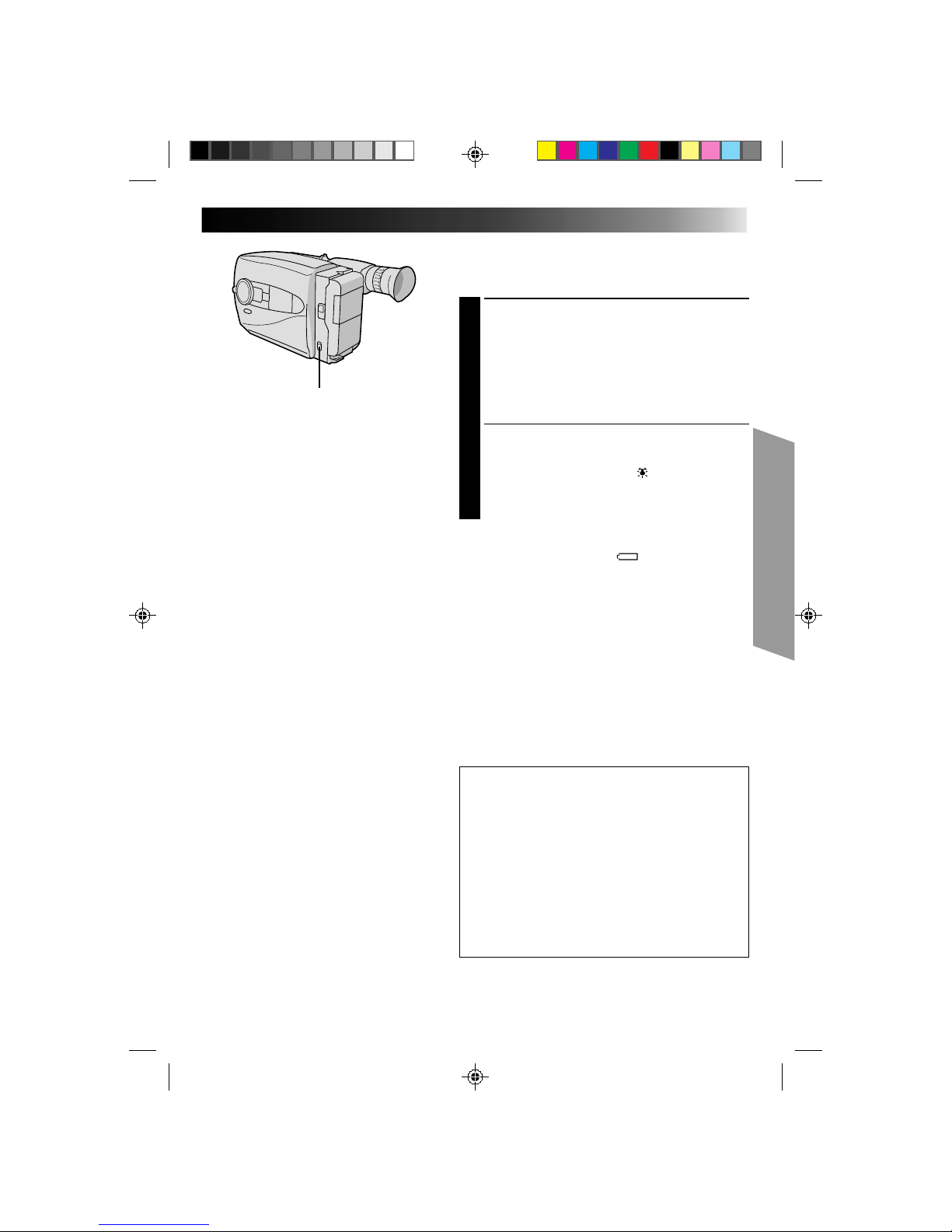
Video Light
When natural lighting is too dim, you can brighten the
scene by using the built-in video light.
SET VIDEO LIGHT
1
Set the LIGHT ON/AUTO/OFF as required.
ON : Always keeps the light on as long as the
camcorder is turned on.
AUTO : Automatically turns on the light when the
camcorder senses insufficient lighting on
the subject.
OFF : Turns off the light.
•The video light can be used with the camcorder’s
power on.
•It is recommended to set the white balance
(Z pg. 23) to indoor mode ( ) when you use the
video light.
•When not using the video light, turn it off to save
battery power.
NOTES:
●
Even if the battery indicator ( ) does not blink in the
viewfinder, if the battery pack’s charge is low, the
camcorder may turn off automatically when you turn
on the video light, or when you start recording with the
video light turned on.
●
When the LIGHT ON/AUTO/OFF switch is set to
“AUTO”:
•
Depending on the lighting conditions, the video light
may keep turning on and off. In this case, manually
switch the light on or off using the LIGHT ON/
AUTO/OFF switch.
•
While the Sports or High-Speed Shutter mode
(Z pg. 27) is engaged, the light is likely to stay on.
•
While the Twilight mode (Z pg. 27) is engaged, the
light will not activate.
DANGER
•The video light become extremely hot. Do not
touch it either while in operation or soon after
turning it off, otherwise serious injury may result.
•Do not place the camcorder into the carrying case
immediately after using the video light, since it
remains extremely hot.
•When operating, keep a distance of about 30 cm.
(1 ft.) between the video light and people or
objects.
•Do not use near flammable or explosive materials.
•It is recommended that you consult your nearest
JVC dealer for replacing the video light.
LIGHT ON/AUTO/OFF
Page 20
20
Date/Time Insert
This feature allows you to display the date and time in your
viewfinder and on a connected TV.
NOTE:
You should already have performed the Date/Time
Setting procedure (Z pg. 11). If you haven’t, do so
before continuing.
DISPLAY
CHOOSE DISPLAY MODE
1
Press DISPLAY during Record–Standby to cycle
through the available modes as shown in the
illustration at left.
NOTES:
●
The selected display can be recorded.
●
If you don't want to record the display, select Date-off
mode before shooting.
●
If you want to delete the display during shooting, press
DISPLAY.
●
If you want to call back a deleted display, engage the
Record-Standby mode and then press DISPLAY to
select the desired display mode.
RECORDING
Advanced Features
DEC 25. 96
PM 3:29:43
Date display
Time display
Date/Time display
Date/Time-off mode
Date display
DEC 25. 96
DEC 25. 96
PM 10: 59:20
Date/Time display
Time display
PM 10: 59:20
DISPLAY
Page 21
21
Quick Rec
Records a scene for 5 seconds, providing quick scene
transitions like those seen in TV programmes.
1
During Record–Standby, press and release QUICK
REC. Recording starts, and after 5-second
recording is finished, the camcorder reenters the
Record–Standby mode automatically.
•To continue shooting longer than 5 seconds,
press and hold QUICK REC. Recording continues
as long as QUICK REC is kept pressed.
NOTES:
●
The Fade/Wipe (Z pg. 28) cannot be activated by
pressing QUICK REC.
●
QUICK REC cannot be used during Animation and
Time-Lapse (Z pg. 35).
QUICK REC
Page 22
22
RECORDING
Advanced Features (cont.)
+
02
+
06
–
06
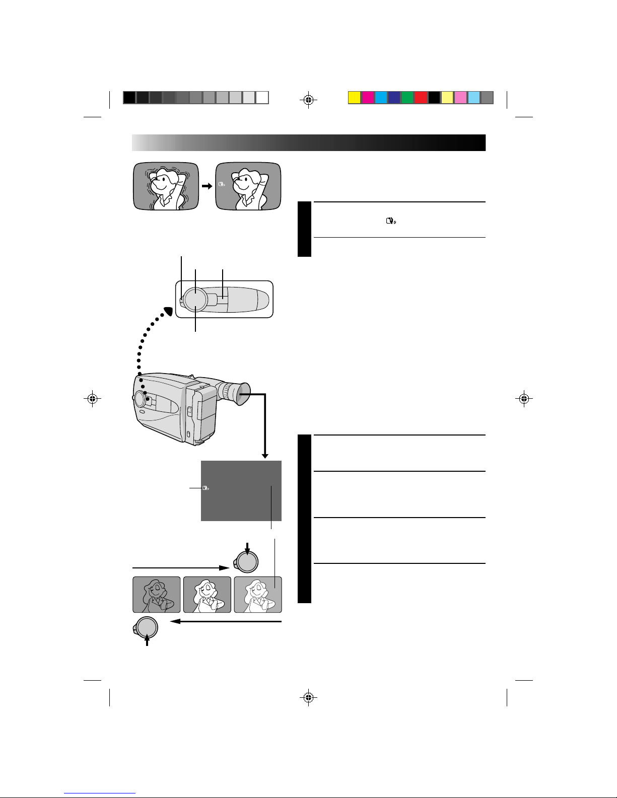
Digital Image Stabilizer
This feature compensates for unstable images caused by
camera-shake, particularly noticeable at high
magnification.
ACTIVATE D. I. STABILIZER
1
Press D.I.STABILIZER. “ ” appears in the viewfinder.
•To switch off the Digital Image Stabilizer, press
D.I.STABILIZER. The indicator disappears.
NOTES:
●
Accurate stabilization may not be possible if hand
shake is excessive, or under the following conditions:
•
When shooting subjects with vertical or horizontal
stripes
•
When shooting dark or dim subjects
•
When shooting subjects with excessive backlighting
•
When shooting scenes with movement in various
directions
•
When shooting scenes with low-contrast
backgrounds
●
Switch off D.I.S. when recording with the camcorder
on a tripod.
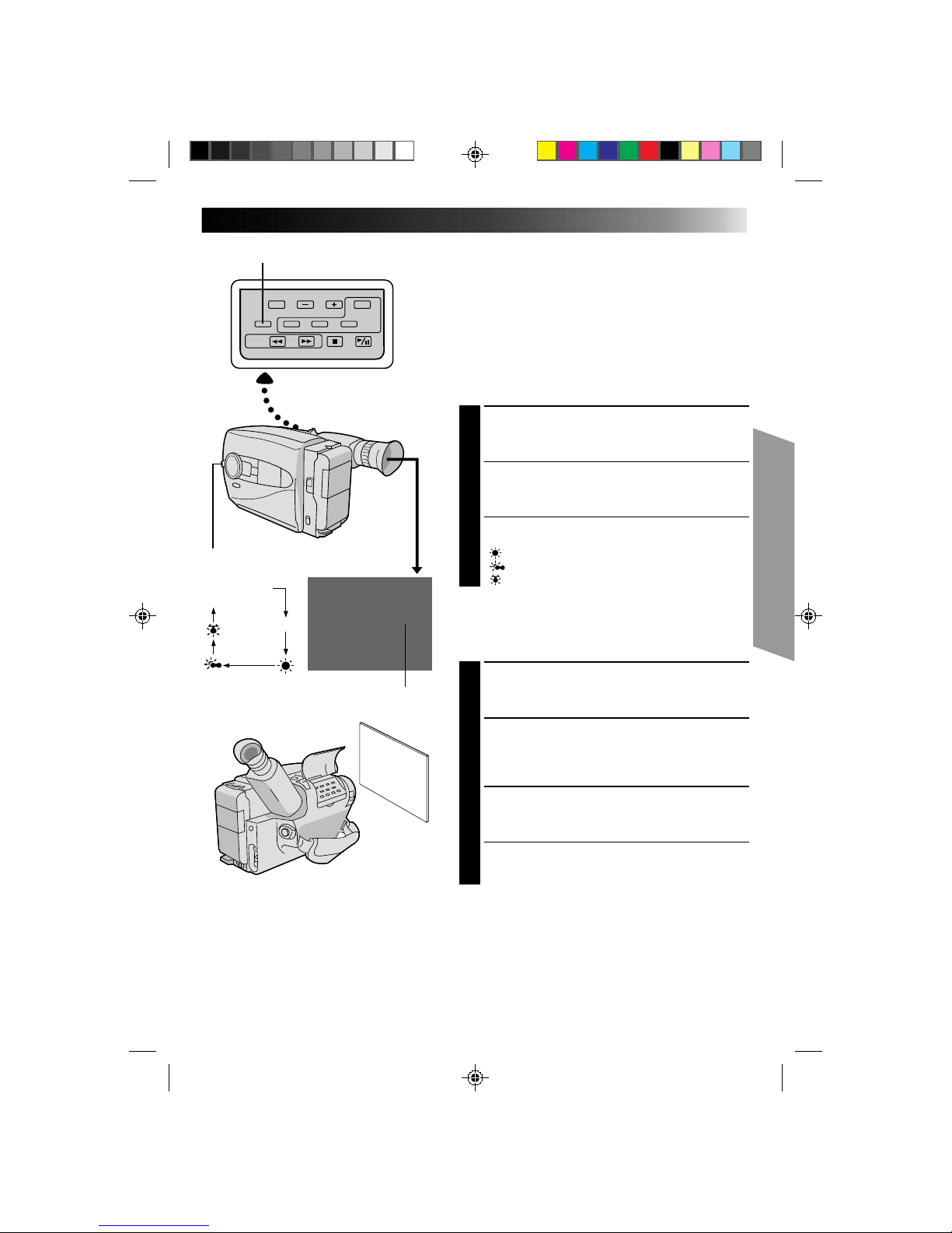
Exposure Control
This feature automatically adjusts the iris for the best
available picture quality, but you can override and make
the adjustment manually.
SELECT SHOOTING MODE
1
Set the Shooting Mode selector to “PRESET”.
BRIGHTEN IMAGE
2
Press + (maximum +06). The Exposure level
indicator appears in the viewfinder.
OR . . .
DARKEN IMAGE
Press – (maximum –06). The Exposure level
indicator appears in the viewfinder.
When you want to return to the factory setting . . .
RESTORE INITIAL SETTING
3
Press + and – simultaneously. The standard setting is
immediately restored and the Exposure level
indicator disappears.
To brighten the image
To darken the image
+
D.I. STABILIZER
Exposure Level Indicator
Viewfinder
–
Shooting Mode Selector
D.I.S. Indicator
Page 23
23
MWB
No indication
(Auto)
MWB
White Balance Adjustment
This camcorder’s Automatic Color Temperature system
senses the color temperature of the ambient lighting for
automatic white balance adjustment. However, precise
color adjustment is not possible under the following
conditions:
•When an object is in various shades of the same color.
•When a predominantly red or brown object is being
shot outdoors.
In these cases, use the camcorder’s built-in preset filters
for white balance adjustment.
SELECT SHOOTING MODE
1
Set the Shooting Mode selector to “PRESET”.
SELECT FUNCTION
2
Press MWB (Manual White Balance) until the
required indication appears in the viewfinder.
“MWB” .... With a memorized personal White
................Balance setting (see below)
“ ” ......... Outdoors on sunny day
“ ” ........ Outdoors on cloudy day
“ ” ..........Light source is halogen or tungsten lamp
MWB sets the color temperature for the subject’s light
source so you can shoot with natural colors that are
unaffected by surroundings, even when there are
multiple subjects with different color temperatures.
SELECT SHOOTING MODE
1
Set the Shooting Mode selector to ”PRESET”.
ADJUST FOCUS
2
Point the camcorder at a white, flat object such as a
sheet of white paper, and adjust focus manually
(Z pg. 25).
ADJUST WHITE BALANCE
3
Press MWB until “MWB” appears, then press and
hold MWB for more than 3 seconds.
•“MWB” blinks in the viewfinder during
adjustment, then stops blinking but stays lit when
adjustment is complete.
NOTES:
●
To switch to automatic white balance adjustment, press MWB until the indication disappears, or turn the
Shooting Mode selector to “FULL AUTO”.
●
Re-adjust the White Balance mode when the lighting has changed, when the camcorder has been turned on and
off again, or when the Shooting Mode selector’s position has been changed.
●
It is helpful to connect your camcorder to a color monitor when adjusting the white balance
(“Basic Connections”
Z
pg. 37).
●
When adjusted by putting colored paper in front of the subject in step 2 (“ADJUST FOCUS”), this unit makes its
color temperature standard for automatic white balance. So you can enjoy shooting with different colors. For
example, when adjusting with red, blue or yellow colors, the image becomes the color which aproximates to
green, orange or purple respectively.
Shooting Mode Selector
White balance mode indicator
MWB
Page 24
24
RECORDING
Advanced Features (cont.)
Focusing
Auto Focus
The camcorder’s Full Range AF system offers continuous
shooting ability from close-up to infinity. However,
correct focus may not be obtainable in the situations
listed below (in these cases use manual focusing):
•When two subjects overlap in the same scene.
•When illumination is low.*
•When the subject has no contrast (difference in
brightness and darkness), such as a flat, one-color wall,
or a clear, blue sky.*
•When a dark object is barely visible in the viewfinder.*
•When the scene contains minute patterns or identical
patterns that are regularly repeated.
•When the scene is affected by sunbeams or light
reflecting off the surface of a body of water.
•When shooting a scene with a high-contrast
background.
* The low-contrast warning “
” appears in the
viewfinder.
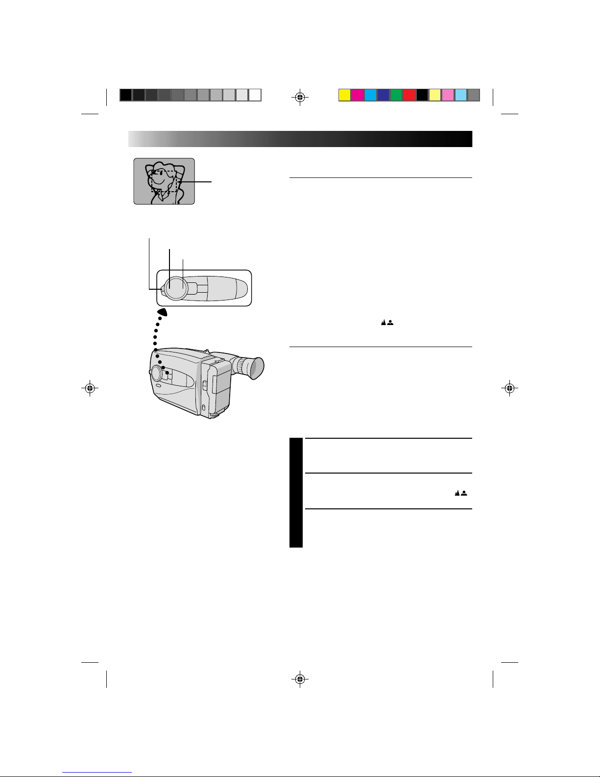
Focus Lock
This feature locks the focus in place, which is especially
helpful in the following situations:
•When things pass between your subject and the
camcorder. Engage the focus lock function to lock your
subject in before recording.
•When you want your subject to be focused, and to
appear in a corner of the screen. First, center on the
subject and focus using auto focus mode. Then engage
the focus lock function and move the camcorder until
the subject is where you want it.
SELECT SHOOTING MODE
1
Set the Shooting Mode selector to “PRESET”.
LOCK FOCUS
2
Press FAR or NEAR. The focus lock indication “ ”
appears in the viewfinder.
RELEASE FOCUS LOCK
3
Press FAR and NEAR simultaneously. The
focus lock indication disappears.
NOTES:
●
If the lens is smeared or blurred, accurate focusing is
not possible. Keep the lens clean, wiping with a piece
of soft cloth if it gets dirty. When condensation occurs,
wipe with a soft cloth or wait for it to dry naturally.
●
When shooting a subject close to the lens, zoom-out
first (Z pg. 17). If zoomed-in in the auto focus mode,
the camcorder could automatically zoom out
depending on the distance between the camcorder and
the subject. *When Tele Macro is activated, the
camcorder will not zoom out automatically.
Focus
detection zone
FAR
NEAR
Shooting mode selector
Page 25
25
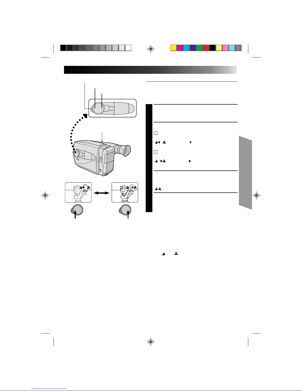
Manual Focus
NOTE:
You should already have made the necessary viewfinder
adjustments (Z pg. 10). If you haven’t, do so before
continuing.
SELECT SHOOTING MODE
1
Set the Shooting Mode selector to “PRESET”.
ADJUST FOCUS
2
A
TO FARTHER SUBJECT
2
Press and hold FAR . The Manual Focus indications
“ ” appear and “ ” blinks.
Go to step 3.
B
TO NEARER SUBJECT
Press and hold NEAR. The Manual Focus indications
“ ” appear and “ ” blinks.
Go to step 3.
LOCK FOCUS
3
Release FAR or NEAR. The focus
indication is replaced by the focus lock indication
“ ” and the adjusted focus is locked in.
RELEASE MANUAL FOCUS MODE
4
Press FAR and NEAR simultaneously. The Manual
Focus mode is immediately released and the focus
lock indication disappears.
NOTES:
●
Be sure to focus the lens in the maximum telephoto
position when you use the Manual Focus mode. If you
focus in on a certain subject in the wide-angle position,
sharply focused images cannot be obtained when
zoomed up because the depth-of-field is reduced at
longer focal lengths.
●
When the focus level cannot be adjusted any farther or
closer, “ ” or “ ” will blink.
FAR
NEAR
Power zoom lever
Shooting mode selector
Page 26
26
1 Cinema
2 Sepia
3 Twilight
4 Sports
5 HI.S 1/2000
OFF
RECORDING
Advanced Features (cont.)
Program AE With Special Effects
Useful in making the picture look creative and attractive.
Effects can be selected during recording, as well as in
Record–Standby.
SELECT SHOOTING MODE
1
Set the Shooting Mode selector to either “FULL
AUTO” or “PRESET”.
If you set to “FULL AUTO”, . . .
.... only the Cinema mode can be activated.
If you set to “PRESET”, . . .
.... you can choose any one of the 5 effects
available.
SELECT EFFECT
2
If you set to “FULL AUTO”, . . .
.... pressing EFFECT/PROG.AE turns the Cinema
mode on and off.
If you set to “PRESET”, . . .
.... pressing EFFECT/PROG.AE brings up the Effect
menu. Press again to move the highlight bar to
the desired effect. Once you decide on an
effect, it is selected and activated, and its
indicator appears, within 2 seconds.
•If you started this procedure in the Record–
Standby mode, press RECORDING START/STOP
to begin recording at this point.
DEACTIVATE EFFECT
3
When the Shooting Mode Selector is set to “FULL
AUTO”, . . .
.... press EFFECT/PROG.AE.
When set to “PRESET”, . . .
.... press EFFECT/PROG.AE to bring up the Effect
Menu, and press again to move the highlight bar
to “OFF”.
Shooting Mode Selector
EFFECT/PROG.AE
FAR
NEAR
+
Effect menu
–
EFFECT/PROG. AE indicator
Page 27
27
INDICATION MODE EFFECT
CINEMA
Adds black bars to the top and bottom of the screen to produce a
cinema-like “16:9 wide-screen” effect.
SEPIA
The picture becomes sepia-tinted (reddish brown) monochrome,
creating the look of an old photograph.
TWILIGHT
Makes dusk and twilight scenes, etc. look more natural and
dramatic. White balance is set to “ ”. Press MWB if you want to
change the setting.
SPORTS
Automatically adjusts to high shutter speed (1/250 to 1/500) to
clearly capture fast-moving action with less blur. Clarity is
especially noticeable during slow motion or still playback on a
VCR. Great for sports, races, etc.
HI-SPEED
Captures even faster action than Sports effect.
SHUTTER
(1/2000)
NOTES:
●
When the Sepia effect is activated, pressing MWB (manual white balance) has no effect.
●
Certain effects cannot be used together with other functions. When an effect not usable in the present
situation is selected, its indicator blinks.
Page 28

28
RECORDING
Advanced Features (cont.)
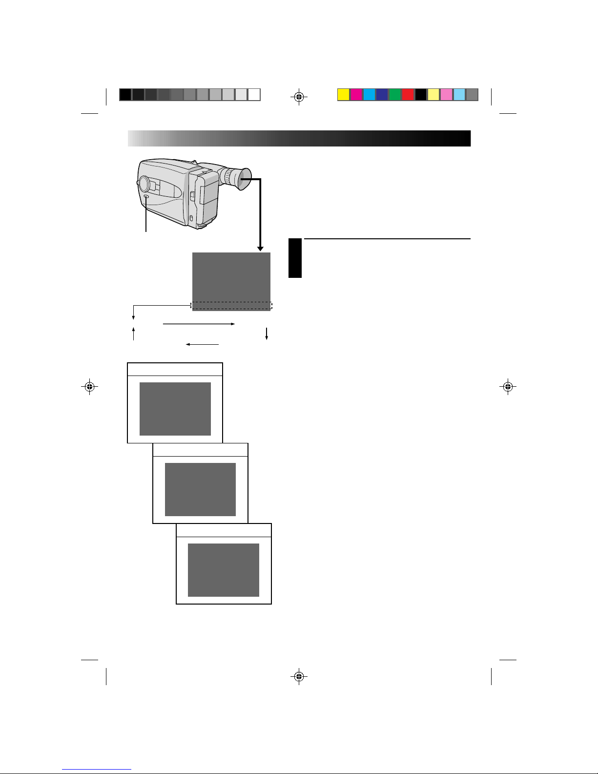
Fade/Wipe
These effects let you make pro-style scene
transitions.
SELECT SHOOTING MODE
1
Set the Shooting Mode selector to either “FULL
AUTO” or “PRESET”.
If you set to “FULL AUTO”, . . .
.... only the Black Fader mode is available.
If you set to “PRESET”, . . .
.... you can choose any one of the effects available.
RESERVE EFFECT
2
If you set to “FULL AUTO”, . . .
.... pressing FADE/WIPE turns the Black Fader
mode on and off.
If you set to “PRESET”, . . .
.... pressing FADE/WIPE brings up the Fade/Wipe
menu. Press again to move the highlight bar to
the desired effect. Once you decide on an
effect, it is selected and reserved, and its
indicator appears, within 2 seconds.
START RECORDING
3
Press RECORDING START/STOP to start recording
and activate a fade- or wipe-in.
OR . . .
END RECORDING
Press RECORDING START/STOP to stop recording
and engage a fade- or wipe-out.
DEACTIVATE EFFECT
4
When the Shooting Mode Selector is set to “FULL
AUTO”, . . .
.... press FADE/WIPE.
When set to “PRESET”, . . .
.... press FADE/WIPE to bring up the Fade/Wipe
menu, then press again to move the highlight
bar to “OFF”.
NOTE:
When the Shooting Mode selector is set to “FULL AUTO”,
after a fade-in, Black Fader is no longer reserved. To
reserve it for a fade-out, press FADE/WIPE. “
B
K
” appears
in the viewfinder.
B
K
1 Black Fader
2 Blue Fader
3 Mosaic Fader
4 Shutter Wipe
5 Slide Wipe
OFF
B
K
C
Shooting mode selector
FADE/WIPE
Fade/Wipe menu
FADE/WIPE indication
Page 29
29
B
K
BLACK FADER
Fades in/out to a black screen.
C
BLUE FADER
Fades in/out to a blue screen.
MOSAIC FADER
Gradually turns/returns the picture into/from a
mosaic pattern.
SHUTTER WIPE
A black screen moves in from the top and bottom,
closing over the image like a shutter, or a new
image pushes open the black screen vertically from
the center.
SLIDE WIPE
A black screen moves in from the left to gradually
cover the image, or a new image moves in from
right to left.
Page 30
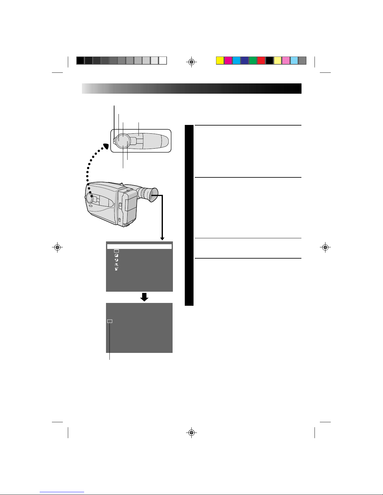
30
Using Menu For Detailed Adjustment
This camcorder is equipped with Multi-Function Control,
an easy-to-use, on-screen menu system that simplifies
many of the more detailed camcorder settings.
SELECT SHOOTING MODE
1
Set the Shooting Mode selector to “PRESET”.
ACCESS MAIN MENU SCREEN
2
Press MENU.
SELECT FUNCTION
3
Press + or – to place the highlight bar on the desired
function.
MAKE SETTING
4
The setting procedure depends on the function you
select.
If you select, Tele Macro, Gain Up, Color Filter or
Tape Length, . . .
.... press FAR or NEAR to cycle through the choices
until the desired setting appears. Then go to step
8.
If you select Title or Date/Time, . . .
.... press NEAR to access the selection menu for
each function (Title – Z pg. 32; Date/Time –
Z pg. 11).
If you select “Sub Menu”, . . .
.... press NEAR to bring up the Sub Menu screen.
Go to step 5.
SELECT FUNCTION AT SUB MENU
5
Press + or – to place the highlight bar on the desired
option, then press NEAR. The selected item begins
blinking.
CHANGE SETTINGS
6
Press + or – to change the displayed setting of the
selected function, then press FAR to enter your
choice. The selected item stops blinking.
CLOSE SUB MENU
7
Press FAR , and setting is complete. The Sub menu
screen disappears and the Main Menu screen
reappears.
•To go directly past the Main Menu screen to the
normal screen, press MENU.
CLOSE MAIN MENU
8
Press MENU. The normal screen reappears.
RECORDING
Advanced Features (cont.)
Tele Macro OFF
Gain Up AGC
Color Filter NOR.
Tape Length T30
Title
Date/Time
Sub Menu
Interval Timer OFF
Rec Time OFF
JLIP ID NO. 07
Tally ON
PAUSE
l
Shooting mode selector
FAR
NEAR
MENU+
–
If any settings in the Main Menu have been
changed from the factory settings, this mark
appears in the viewfinder.
Sub Menu screen
Main Menu screen
Page 31

31
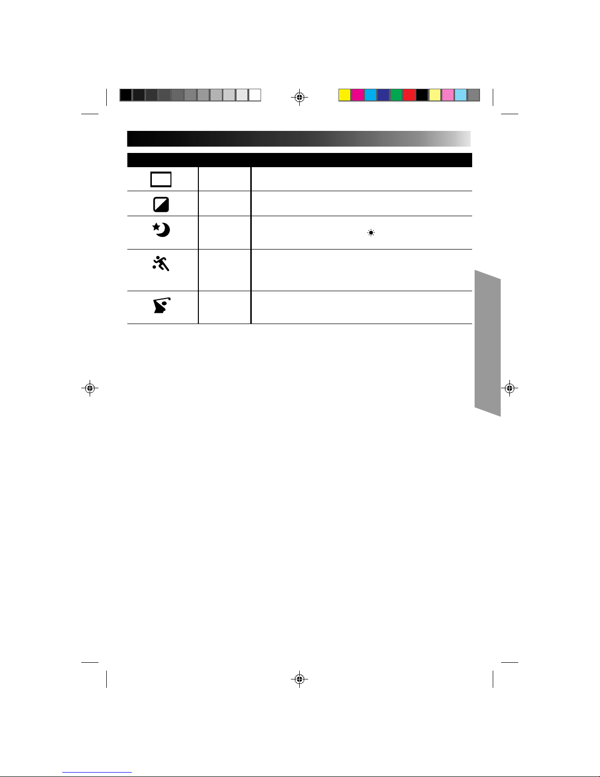
MAIN MENU
Tele Macro OFF Usually set to this position.
lON Usually the distance to a subject where the lens is in focus
depends on the zoom magnification. Unless there is a
distance more than 1 m (3.3 ft.) to the subject, the lens is out of
focus at the maximum telephoto setting. When set to “ON”, you
can shoot a subject as large as possible at a distance of
approx. 60 cm (2 ft.).
•Depending on the zoom position, the lens may go out of
focus.
Gain UP AGC Allows you to record a subject in a dark environment. It
delivers a brighter, if slightly coarse, picture.
lOFF Allows you to shoot dark scenes with no picture brightness
adjustment.
Color Filter NOR For normal shooting with no color adjustment.
lRED Gives recording a reddish tint.
lBLUE Gives recording a bluish tint.
Tape Length Allows you to set the tape length depending on the tape used (Z pg. 12).
Title Allows you to superimpose a preset title onto a scene (Z pg. 32).
Date/Time Allows you to set the current date and time (
Z pg. 11).
= Factory setting
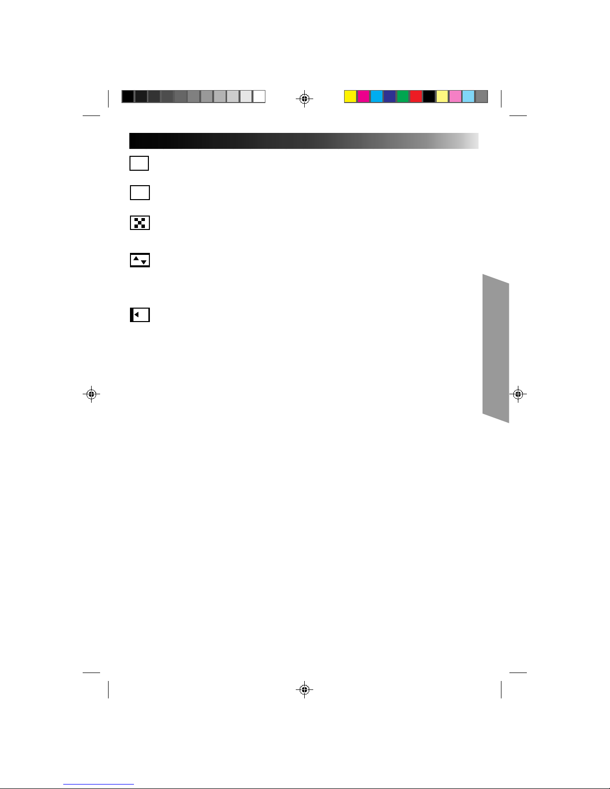
Tally ON The tally lamp comes on to signal the start of recording.
OFF The tally lamp remains off at all times.
Interval Timer and These features allow you to set the parameters for Self-Timer
Rec. Time (Z pg. 34), Animation and Time-Lapse recording (Z pg. 35).
JLIP ID NO. This number will be necessary in the future when connecting the
camcorder to a device such as a computer using the JLIP terminal.
The numbers range from 01 — 99.
SUB MENU
Page 32

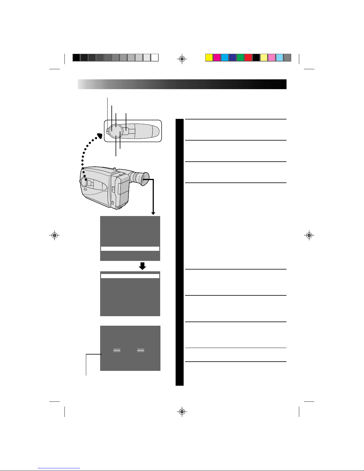
32
Instant Titles
You can superimpose one of 8 preset titles, or a title you
made yourself, onto a scene.
SELECT SHOOTING MODE
1
Set the Shooting Mode selector to “PRESET”.
ACCESS MAIN MENU SCREEN
2
Press MENU.
ACCESS INSTANT TITLE MENU
SCREEN
3
Press + or – to move the highlight bar to “Title”, then
press NEAR. The Title menu appears.
SELECT PRESET TITLE
4
Press + or – to move the highlight bar to the desired
title. (To create an original title, refer to page 33.)
DISPLAY PRESET TITLE
5
Press MENU. The Title menu disappears, and the
selected title is displayed on the screen.
FAR NEAR
MENU
Happy Birthday
Our Vacation
Merry Christmas
A Special Day
Happy Holidays
Our New Baby
Wedding Day
Congratulations
(Set Character)
OFF
Congratulations
Tele Macro OFF
Gain Up AGC
Color Filter NOR.
Tape Length T30
Date/Time
Sub Menu
Title
RECORDING
Advanced Features (cont.)
+
–
Page 33

33
Happy Birthday
Our Vacation
Merry Christmas
A Special Day
Happy Holidays
Our New Baby
Wedding Day
Congratulations
(Set Character)
OFF
J K L M N O P Q R S
T U V W X Y Z Ä Ö Ü
À È Ì Ò Ù Ñ Æ Ø Å &
: . , ’ – / ! ? ¿ k
0 1 2 3 4 5 6 7 8 9
A B C D E F G H I
End Clear
SET : MENU KEY
J K L M N O P Q R S
T U V W X Y Z Ä Ö Ü
À È Ì Ò Ù Ñ Æ Ø Å &
: . , ’ – / ! ? ¿ k
0 1 2 3 4 5 6 7 8 9
A B C D E F G H I
End
I L I
I L I KE YOU
k
Clear
SET : MENU KEY
Character Generator
You can enter an original title of up to 18 characters.
Perform steps 1, 2 and 3 of the “Instant Title” procedure
(Z pg. 32) before continuing.
ACCESS CHARACTER SET MENU
1
Press + or – to move the highlight bar to “(Set
Character)”, then press NEAR. The Character Set
menu appears.
INPUT CHARACTERS
2
Press +, –, FAR or NEAR to move the blinking cursor
to the desired character, then press MENU. The
selected characters appear at the bottom of the
screen. Repeat as many times as desired (max. 18).
•To select the location of the next character, press
+, –, FAR or NEAR to move the blinking cursor to
the row of squares at the bottom of the screen,
then press FAR or NEAR to move the blinking
cursor underneath the desired location. Press +
when you’re done, and the blinking cursor returns
to the character grid.
END CHARACTER SETTING
3
Press +, –, FAR or NEAR to move the cursor to
“End”, then press MENU. The Character Set menu
disappears and the Preset Title menu reappears.
Press MENU to return to the normal screen.
NOTE:
To erase a character you entered mistakenly, place the
cursor by “Clear” by pressing +, –, FAR or NEAR, then
press MENU. All characters are deleted at once. Or, to
erase selected characters only, place the blinking cursor
at the character at the bottom you want to replace, then
press +/–. “ ” in the top left corner is highlighted.
FAR NEAR
MENU
+
–
Page 34

34
JLIP ID NO. 07
Tally ON
Interval Timer OFF
Rec Time OFF
Tele Macro OFF
Gain Up AGC
Color Filter NOR.
Tape Length T30
Date/Time
Sub Menu
Title
1min
1s
RECORDING
Advanced Features (cont.)
–
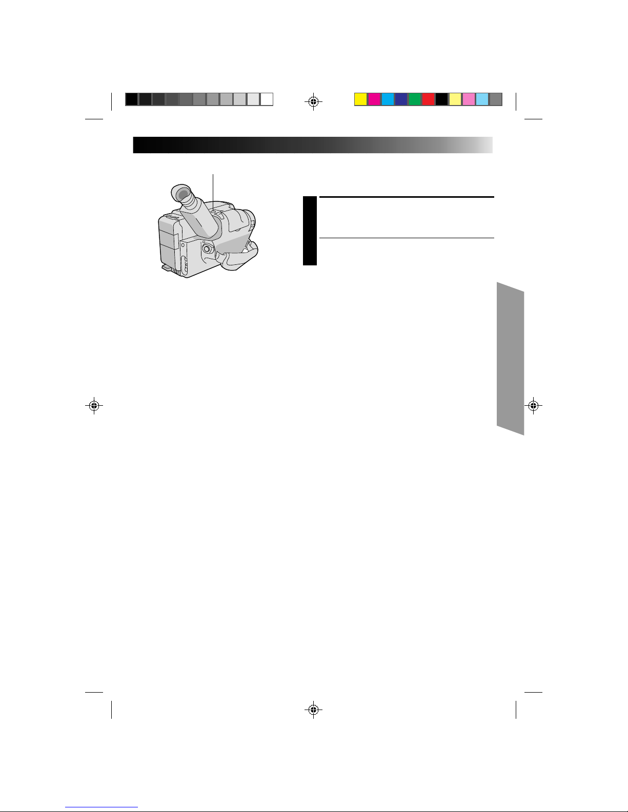
Self-Timer
You can set the delay between pressing RECORDING
START/STOP and the actual start of recording. If you
secure the camcorder, you (or whomever is operating the
camcorder) can enter the scene before recording starts.
ENGAGE RECORD-STANDBY
MODE
1
Make sure the lens cover is open, then set the Power
switch to “CAMERA”.
SELECT MODE
2
Set the Shooting Mode selector to “PRESET”.
ACCESS MAIN MENU SCREEN
3
Press MENU.
ACCESS SUB MENU SCREEN
4
Press – to move the highlight bar down to “Sub
Menu”, then press NEAR. The Sub Menu screen
appears.
SET INTERVAL TIME
5
Press – to move the highlight bar down to “Interval
Timer”, press NEAR, then press + or – to cycle
through the choices. Stop when the desired time
appears. Choose from “15S”, “30S”, “1min”,
“5min”, or select to turn the function “OFF”. Then
press FAR twice to return to the Main Menu screen.
CLOSE MAIN MENU
6
Press MENU.
START DELAYED RECORDING
7
Press RECORDING START/STOP. If you set the tally
lamp to “ON” (Z pg. 31), it begins blinking, and
the blinking frequency increases about 5 seconds
before recording is to start. Once recording begins,
the lamp stops blinking but stays lit.
To Release Self-Timer . . .
.... while the tally lamp is blinking, press RECORDING
START/STOP to stop the blinking, then set “Interval
Timer” to “OFF” or press INT. TIME on the remote
control until “ ” disappears.
.... while the tally lamp is lit but not blinking, press set
“Interval Timer” to “OFF” or press INT. TIME on the
remote control until “ ” disappears.
NOTE:
Instead of performing steps 2 – 6, you can set the interval
time by pressing INT. TIME on the remote control.
FAR NEAR
MENU
+
Tally lamp
RM-V705U (provided)
Main Menu Screen
Sub Menu Screen
Interval Timer Indicator
Recording
Time Indicator
START/STOP
INT. TIME
REC TIME
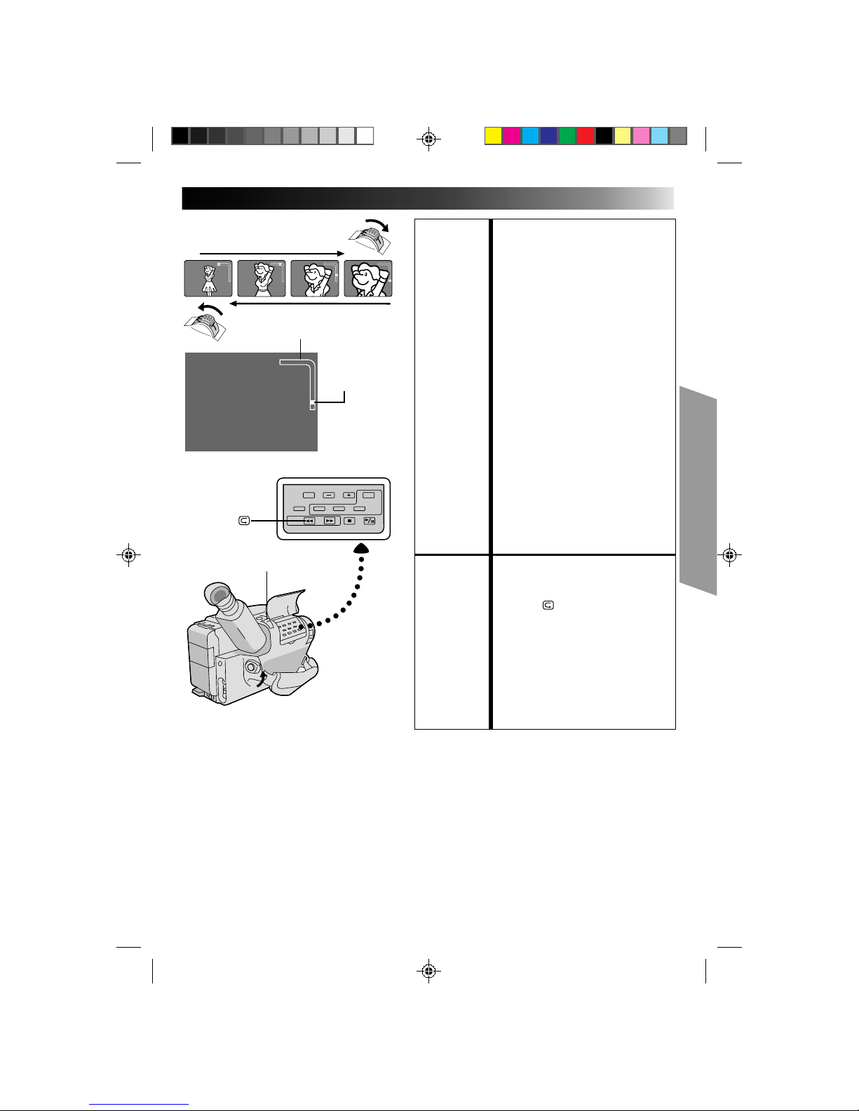
Page 35

35
Animation
Give stationary scenes or objects an illusion of
movement. This function allows you to shoot a
series of pictures, each slightly different, of the same
object for a brief period of time.
ENGAGE RECORD–STANDBY
MODE
1
Make sure the lens cover is open, then set the
power switch to “CAMERA”.
SET RECORDING SPEED
2
Set SP/EP to SP (Z pg. 13).
SET RECORDING TIME
3
Press REC TIME on the remote control. Four
choices are available, and they appear in the
following order (each time REC TIME is
pressed): 1/4S (one-fourth of a second), 1/2S
(one-half of a second), 1S (one full second) and
5S (five seconds). Press again to release the
Animation mode.
•You can also set the recording time in the
Sub Menu screen (Z pg. 30). Press “–” to
move the highlight bar down to “Rec Time”,
press NEAR, and press + or – to cycle
through the choices. Then press MENU.
START RECORDING
4
Press RECORDING START/STOP after focusing
on the subject. The recording stops
automatically after the selected period of time.
ASSEMBLE SERIES OF
PICTURES
5
Repeat steps 3 and 4 for the desired number of
pictures.
CHECK YOUR WORK
6
Play back the series of pictures to see if the
results were satisfactory.
RELEASE ANIMATION MODE
7
Press REC TIME until “ ” disappears from the
viewfinder, or set “Rec Time” in the Sub Menu
pscreen to “OFF”.
NOTES:
●
For best results, make sure the camcorder is
secured when shooting in Animation or
Time-Lapse mode.
●
Fade-in/out cannot be performed during
Animation or Time-Lapse shooting.
●
Before performing other operations following
Animation or Time-Lapse recording, make sure
the Animation or Time-Lapse mode is deactivated.
Time-Lapse
You can record sequentially at preset time spans.
Leaving the camcorder aimed at a specific subject,
you can record subtle changes over an extended
period of time.
ENGAGE RECORD–STANDBY
MODE
1
Make sure the lens cover is open, then set the
power switch to “CAMERA”.
SET RECORDING SPEED
2
Set SP/EP to SP (Z pg. 13).
SET RECORDING TIME
3
Press REC TIME on the remote control. There
are four choices available, and they appear in
the following order (each time REC TIME is
pressed): 1/4S, 1/2S, 1S, and 5S. Press again to
reset.
•You can also set the recording time in the
Sub Menu screen. Press “–” to move the
highlight bar down to “Rec Time”, and press
NEAR, then press + or – to cycle through the
choices.
SET INTERVAL BETWEEN
RECORDINGS
4
Press INT. TIME on the remote control. There
are five choices available, and they appear in
the following order (each time INT. TIME is
pressed): OFF, 15S, 30S, 1 min, and 5 min.
Press again to reset.
•You can also set the interval time in the Sub
Menu screen. Press “–” to move the highlight
bar down to “Interval Time”, press NEAR,
and press + or – to cycle through the choices.
•Exposure control (Z pg. 22), manual
focusing (Z pg. 25) and D.I.S. settings
(Z pg. 22) should be performed at this point.
Once you perform step 5, these settings
cannot be changed.
START TIME-LAPSE
RECORDING
5
Press RECORDING START/STOP. Recording
and intervals alternate automatically.
RELEASE TIME-LAPSE MODE
6
To release when the tally lamp is not blinking,
press INT. TIME and REC TIME repeatedly
until “
” and “ ” disappear. To release
when the tally lamp is blinking, press
RECORDING START/STOP to stop the
blinking, then press INT. TIME and REC TIME
repeatedly until “
” and “ ” disappear, or
set “Interval Timer” and “Rec Time” in the Sub
Menu screen to “OFF”.
Page 36

36
+
PLAYBACK
Using The Cassette Adapter
Cassette Adapter (VHS PlayPak)
Use this to play back a VHS-C video cassette recorded
with this camcorder. It is fully compatible with any VHS
video cassette recorder. The C-P7U adapter is battery
powered and automatically performs tape loading and
unloading.
INSERT BATTERY
1
Slide the battery cover up to remove it, and install
one “AA(R6)” size battery as shown in the
illustration at left. Then reattach the cover.
INSERT CASSETTE IN ADAPTER
2
Slide the latch to open the adapter compartment
door, then insert the cassette and close the
compartment door.
PLAY BACK ON CONNECTED VCR
3
Load the cassette adapter into the VCR and play the
tape back as you would any other.
REMOVE CASSETTE FROM
ADAPTER
4
Slide the latch and the compartment door opens
automatically. Then insert your finger in the hole on
the underside of the adapter as shown in the
illustration at left, push up and remove the cassette.
NOTES:
●
During tape loading and unloading, do not touch the
reels for safety and tape protection.
●
During special-effect playback (slow motion, still
frame, etc.), the picture may vibrate or noise bars may
appear on the screen.
●
To record on a VCR using a compact cassette and the
adapter, cover the adapter’s recording safety hole with
adhesive tape.
VCR
Compartment door
Sliding latch
Compact video cassette
Recording safety hole
Reels
Page 37

37
A
B
There are three basic types of connections. When making
the connections, refer also to your VCR and TV
instruction manuals.
Connection To A VCR [A]
(Editing, Dubbing and Playback)
NOTE:
Use the optional Audio and Video cables.
CONNECT CAMCORDER TO VCR
1
As shown in the illustration at left, connect the
optional Audio and Video cables between the
AUDIO and VIDEO connectors on the camcorder
and those on the VCR.
SUPPLY POWER
2
Turn on the camcorder, the VCR and the TV.
SELECT MODE
3
Set the VCR to its AUX input mode, and set the TV
to its VIDEO mode or channel 3.
Connection To A TV With A/V Input
Connectors [B] (Playback ONLY)
NOTE:
Use the optional Audio and Video cables.
CONNECT CAMCORDER TO TV
1
As shown in the illustration at left, connect the
optional Audio and Video cables between the
AUDIO and VIDEO connectors on the camcorder
and those on the TV.
SELECT MODE
2
Set the TV to its VIDEO or AV mode (as specified in
its instructions).
Connection To A TV With NO A/V Input
Connectors (Playback ONLY)
NOTE:
Use the optional RF-V5U RF unit.
* Refer to the RF-V5U instruction manual for connection
procedure.
NOTES:
●
It is recommended to use the AC Power
Adapter/Charger as the power supply instead
of the battery pack.
●
To monitor the picture and sound from the
camcorder without inserting a tape, set the
camcorder’s Power switch to “CAMERA”,
then set your TV to the appropriate input
mode.
●
If you have a TV or speakers that are not
specially shielded, do not place the speakers
adjacent to the TV as interference will occur
in the camcorder playback picture.
To AUDIO
and VIDEO
connectors
Audio and Video
cables (optional)
To AUDIO and
VIDEO IN
connectors
Antenna
RF unit RF-V5U
(optional)
To AUDIO, VIDEO and
DC OUT connectors
VCR
PLAYBACK
Basic Connections
Page 38

38
M–1:23:45
PLAYBACK
Basic Playback
NOTE:
Make sure you connect your camcorder as directed in
“Basic Connections” (Z pg. 37).
LOAD A CASSETTE
1
Slide EJECT to open the cassette holder, then insert
the cassette with the label facing out. Press PUSH to
ensure the holder is closed and locked.
SELECT MODE
2
Set the Power switch to “PLAY”. The Power On
indicator lights.
PLAYBACK
3
Press PLAY/PAUSE. The playback picture appears in
the viewfinder and the connected TV.
STOP PLAYBACK
4
Press STOP.
Rewind or Fast-forward the tape
Press REW to rewind, or FF to fast-forward the tape
during Stop mode.
NOTE:
The camcorder shuts off automatically after about 5
minutes in STOP mode. To turn on again, set the Power
switch to “POWER OFF”, then to “PLAY”.
FF
REW
POWER
PLAY/PAUSE
STOP
Tape counter
Page 39

39
FEATURE: Manual Tracking
PURPOSE: To eliminate noise bars that appear
on the screen.
OPERATION: 1) Press either TRACKING button as
many times as necessary for best
picture.
NOTES: ●
To reset TRACKING to the original
preset, press both TRACKING
buttons simultaneously.
●
Manual Tracking may not work
with tapes recorded on other VCRs
or camcorders.
FEATURE: Still Playback
PURPOSE: To pause during playback.
OPERATION: 1) Press PLAY/PAUSE during
playback.
2) To resume normal playback, press
PLAY/PAUSE again.
NOTE:
Noise bars appear and pictures may
become monochrome during Still
Playback. This is normal.
FEATURE: Shuttle Search
PURPOSE: To allow high-speed search in either
direction.
OPERATION:
Forward Search
1) Press FF during playback. (Speed is
5 times normal in SP, and 15 times
normal in EP mode.)
Reverse Search
1) Press REW during playback.
(Speed is as noted above.)
NOTE:
Noise bars appear and pictures may
become monochrome or darken in
Shuttle Search. This is normal.
FEATURE: Counter Memory Function
PURPOSE: To make it easier to locate a specific
tape segment.
OPERATION: 1) Press COUNTER R/M and hold for
more than 2 seconds. The counter
resets to “0:00:00”.
2) Press COUNTER R/M. “M
appears.
3) After recording or playback, press
STOP, then REW. The tape
automatically stops at or close to
0:00:00.
4) Press PLAY/PAUSE to start
playback.
NOTES: ●
The counter memory functions in
the FF and REW modes.
●
To disable Counter Memory
Function, press COUNTER R/M so
the “M” disappears.
FF
COUNTER R/M
PLAY/PAUSETRACKING
STOP
PLAYBACK
Features
REW
RM-V705U (provided)
FF
PAUSE
PLAY
REW
Page 40

40
EDITING
Tape Dubbing
CONNECT EQUIPMENT
1
Following the illustration at left, connect the
camcorder and the VCR.
PREPARE FOR DUBBING
2
Set the camcorder’s Power switch to “PLAY”, turn
on the VCR’s power, and insert the appropriate
cassettes in the camcorder and the VCR.
SELECT VCR MODE
3
Engage the VCR’s AUX and Record-Pause modes.
FIND EDIT-IN POINT
4
Engage the camcorder’s Play mode to find a spot
just before the edit-in point. Once it’s reached, press
PAUSE on the camcorder.
START EDITING
5
Press PLAY on the camcorder and engage the VCR’s
Record mode.
STOP EDITING TEMPORARILY
6
Engage the VCR’s Record-Pause mode and press
PAUSE on the camcorder.
EDIT MORE SEGMENTS
7
Repeat steps 4 through 6 for additional editing, then
stop the VCR and camcorder when finished.
Random Assemble Editing [R.A.Edit]
Create edited videos easily using your camcorder as the
source player. You can select up to 8 “cuts” for automatic
editing, in any order you like. R.A.Edit is more easily
performed when the optional RM-V700U MBR
(Multi-Brand Remote) is set to operate with your brand of
VCR (see VCR CODE LIST), but can also be performed by
operating the VCR manually.
CONTINUED ON NEXT PAGE
VCR (Recording deck)
Power switchTo AUDIO and
VIDEO out
connectors
Audio and Video
cable (optional)
To AUDIO and
VIDEO IN
connectors
PLAY/PAUSE
Page 41

41
1
2 3
4
5 6
7
8
9
0
VCR BRAND
NAME
BUTTONS
(A) (B)
GE 1 1
9 2
9 `
9 4
MAGNAVOX 9 5
1 1
7 1
7 6
MITSUBISHI 6 7
6 8
NEC 3 7
3 8
PHILIPS 1 9
9 5
1 1
9 4
9 1
9 6
JVC A
B
C
9 1
9 6
9 3
HITACHI 6 6
6 3
VCR BRAND
NAME
BUTTONS
(A) (B)
PHILIPS 1 2
3 3
SANYO 3 6
3 5
SHARP 1 5
1 `
SONY 6 5
6 `
3 9
3 1
TOSHIBA 6 9
6 1
ZENITH 1 6
RCA 9 2
9 4
6 6
6 3
9 `
PANASONIC 1 3
1 7
1 1
9 4
1 8
VCR CODE LIST
MBR SET
VCR CTL
RM-V700U (optional)
SET REMOTE/VCR CODE
SET REMOTE TO OPERATE VCR
1
Turn off the power to the VCR and point the remote
toward the VCR’s infrared sensor. Then, referring to
the chart at left, press and hold MBR SET, and press
button (A) and then (B).
•The code is automatically set once you release the
MBR SET button, and the VCR’s power comes on.
OPERATE THE VCR
2
Make sure the VCR’s power is on. Then, while
holding VCR CTL, press the button on the remote for
the desired function. The functions the remote can
control are PLAY, STOP, PAUSE, FF, REW and VCR
REC STBY (you don’t need to press VCR CTL for this
one).
You’re now ready to try Random Assemble Editing.
IMPORTANT
Although the MBR is compatible with JVC VCRs and
those of many other makers, it may not work with yours
or may offer limited functions.
NOTES:
●
If the VCR’s power doesn’t come on in step 1, try
another code from the chart.
●
Some brands of VCR don’t come on automatically. In
this case, turn the power on manually and try step 2.
●
If the RM-V700U is not able to control the VCR, use
the controls on the VCR.
MAKE CONNECTIONS
CONNECT TO . . .
1
A
JVC VCR EQUIPPED WITH REMOTE
PAUSE TERMINAL
Connect the editing cable to the Remote PAUSE
terminal.
2
B
JVC VCR NOT EQUIPPED WITH REMOTE
PAUSE TERMINAL
Connect the editing cable to the R.A. EDIT connector.
2
C
NON-JVC VCR WITH NEITHER
Connect the editing cable to the RM-V700U’s
Pause-In jack.
All other connections are as shown in the illustration
on page 42.
CONTINUED ON NEXT PAGE
Page 42

42
A
B
C
IN OUT
ç 1 0:00:25 - -:- -: --
2
3
4
5
6
7
8
COUNTER 0:00:25
TOTAL 0:00:00
IN OUT
ç 1 0:00:25 0:01:05
2 0:03:18 0:03:31
3 0:02:33 0:02:53
4 0:04:11 -- :-- :- -
5
6
7
8
COUNTER 0:04:11
TOTAL 0:01:13
EDITING (cont.)
IN/OUT
PLAY/PAUSE
R.A. EDIT
CANCELREW/FF
To AUDIO and
VIDEO out
connectors
To JLIP
Audio and Video
cable (optional)
Editing cable
(optional 3.5 ø
mini-plug cable)
VCR (Recording deck)
To Remote
PAUSE
To AUDIO and
VIDEO IN
connectors
To Pause-In
CANCEL
RM-V700U
(optional)
ON/OFF
VCR REC STBY
IN/OUT
STOP
PREPARE CAMCORDER
2
Insert a recorded tape and set the Power switch to
“PLAY”.
PREPARE VCR
3
Turn the power on, insert a recordable tape and
engage the AUX mode (refer to VCR’s instructions).
SELECT SCENES
ACCESS R.A. EDIT COUNTER
DISPLAY
1
Press PLAY/PAUSE, then press R.A. EDIT and the
counter display appears in the viewfinder and the
screen of the connected TV.
REGISTER BEGINNING OF SCENE
2
Press REW or FF to locate the beginning of a scene
you want, then press IN/OUT to register that point.
The data appears under IN on the display.
REGISTER END OF SCENE
3
Press REW or FF to locate the end of the scene and
press IN/OUT to register it. The data appears under
OUT on the display. The total time of the registered
scene(s) is displayed at the bottom of the screen.
REGISTER ADDITIONAL SCENES
4
Repeat steps 2 and 3 for each additional scene
(as many as 8).
MAKE CORRECTIONS
5
Press CANCEL during steps 2 and 3 to erase the
most recently registered point.
NOTES:
●
The RM-V700U can be used to operate other camcorder
functions as well. Point the RM-V700U at the camcorder’s
remote sensor and press any of the following buttons
(function apears in parentheses):
— ON/OFF (camcorder R.A. EDIT)
— IN/OUT (camcorder IN/OUT)
— CANCEL (camcorder CANCEL)
●
There must be at least one second between an in-point and
its corresponding out-point.
●
To ensure correct operation, leave at least 15 seconds open
between scenes.
●
Blank portions of tape cannot be registered as in-points or
out-points.
●
If it takes more than 5 minutes to search for an in-point, the
VCR’s Record-Pause mode is cancelled and editing doesn’t
take place.
●
Pressing R.A.EDIT clears all in- and out-points from
memory.
●
Leave a small margin for error around each in-point to
ensure the scene is recorded in its entirety.
Page 43

43
1 3 2
IN OUT IN OUT IN OUT
ORIGINAL TAPE (camcorder)
EDITED TAPE (VCR)
EDIT STOP
AUTOMATIC EDITING TO VCR
ENGAGE VCR’S RECORD–PAUSE
MODE
1
Point the remote control toward the VCR’s infrared
sensor and press VCR REC STBY, or manually
engage the VCR’s Record-Pause mode.
BEGIN AUTOMATIC EDITING
2
Press EDIT on the camcorder, and the previously
selected scenes are copied to the VCR in the
specified order.
END AUTOMATIC EDITING
3
When all selected scenes have been copied, the
camcorder and VCR enter the still or pause mode.
Press STOP on both units.
•When finished editing, be sure to disconnect the
editing cable and the audio/video cable.
NOTES:
●
If you performed step 1C on page 41
(“MAKE CONNECTIONS”), keep the remote control
pointed at the VCR during editing.
●
The on-screen display only appears while the
camcorder searches for each scene.
●
There may be noise at in- or out-points on the edited
tape with certain VCRs.
Page 44

44
w
M–0:12:34
COUNTER R/M
POWER
Insert Editing
You can record a new scene into a previously recorded
tape, replacing a section of the original recording with
minimal picture distortion at the in- and out-points. The
original audio remains unchanged.
NOTE:
Use the RM-V705U remote control unit to perform this
procedure.
SELECT MODE
1
Set the Power switch to “PLAY”.
FIND EDIT-OUT POINT
2
Locate the point and press PAUSE on the camcorder
or the remote control.
RESET COUNTER
3
Press and hold COUNTER R/M for more than
2 seconds to reset the tape counter, then press for
less than 1 second and make sure “M” appears in
the viewfinder.
FIND EDIT-IN POINT
4
Press REW to go a little beyond the beginning of the
scene you want to replace, press PLAY to view the
recorded tape, and press PAUSE at exactly at the
point where the new scene should start.
ENGAGE INSERT EDITING MODE
5
Press and hold INSERT, and without releasing
INSERT, press and release PAUSE. The Insert
mode is engaged, and the scene the camcorder is
aimed at appears on the screen.
BEGIN INSERT EDITING
6
Press RECORDING START/STOP. When the counter
reaches “0:00:00”, editing stops automatically and
the camcorder enters the Insert-Pause mode.
END INSERT EDITING
7
Press STOP.
•If a Fade/Wipe effect was in use during Insert
Editing, wait about 10 seconds after pressing STOP
before performing other operations.
NOTES:
●
After step 5, Retake (Z pg. 18) can be performed.
●
The tape may stop slightly before or after the
designated end point, and noise bars may appear.
Neither indicates a defect in the unit.
●
Only video signal is recorded in the Insert Editing
mode.
EDITING (cont.)
Insert editing
indicator
Viewfinder
Tape Counter
PLAY
REW
PAUSE
INSERT
RM-V705U (provided)
Page 45

45
M-0:05:20
e
Audio Dubbing
You can record a new soundtrack on a prerecorded tape
(normal audio only).
** Perform steps 1, 2 and 3 of the Insert Editing procedure
(Z pg. 44) before continuing.
•The sound comes from the built-in mike.
FIND EDIT-IN POINT
1
Press REW to go a little beyond the beginning of the
scene onto which you want to dub new audio, press
PLAY to view the recorded tape, then press PAUSE
at exactly the point where dubbing should start.
ENGAGE AUDIO DUB STANDBY
MODE
2
Press and hold A. DUB, and without releasing
A. DUB, press and release PAUSE.
BEGIN AUDIO DUBBING
3
Press PLAY/PAUSE. When the counter reaches
“0:00:00”, Audio Dubbing stops automatically and
the camcorder enters the Audio Dub-Standby mode.
END AUDIO DUBBING
4
Press STOP.
NOTE:
●
Do not press FF or REW during Audio Dub-Standby, or
the edit points will not be accurate.
●
If the mike is too close to the TV, or if the TV’s volume
is too high, whistling or howling may occur.
NOTES (for Insert Editing and
Audio Dubbing):
●
Insert Editing and audio Dubbing may not work
correctly if the tape contains blank segments, or if the
recording speed was changed during the original
recording.
●
To edit/dub onto a tape with the recording safety tab
removed, cover the hole with adhesive tape.
●
Do not press STOP during Insert Editing or Audio
Dubbing, or the edit points will not be accurate.
●
During Insert Editing and Audio Dubbing, when Insert–
Pause or Audio Dub–Standby is engaged, the counter
may go slightly past “0:00:00”. Recording, however,
stops at exactly 0:00:00.
Audio dubbing indicator
Mike
Viewfinder
A.DUB
PLAY
REW
PAUSE
RM-V705U (provided)
Page 46

46
USER MAINTENANCE
After Use
1
Set the Power switch to “POWER OFF” to turn off
the camcorder.
2
Slide EJECT to open the cassette holder, then remove
the cassette.
3
Close and lock the cassette holder by pressing
PUSH.
4
Press BATT. RELEASE to remove the battery pack.
5
Slide the LENS COVER open/close switch to close
the lens cover.
Cleaning The Camcorder
CLEAN EXTERIOR
1
Wipe gently with a soft cloth.
CLEAN LENS
2
Blow it with a blower brush, then wipe gently with
lens cleaning paper.
REMOVE EYEPIECE
3
Turn the eyepiece counterclockwise and pull it out.
CLEAN VIEWFINDER
4
Remove dust using a blower brush.
RE-ATTACH EYEPIECE
5
Align the marks, re-attach the eyepiece and turn it
clockwise.
NOTES:
●
Avoid using strong cleaning agents such as benzine or
alcohol.
●
Cleaning should be done only after the battery pack
has been removed or other power units have been
disconnected.
●
Mold may form if the lens is left dirty.
LENS COVER
open/close switch
Set to “POWER OFF”
BATT. RELEASE
EJECT
PUSH
Remove
Marks
Page 47

47
TROUBLESHOOTING
SYMPTOM POSSIBLE CAUSE(S)
POWER
No power is supplied.
The power suddenly goes off and
doesn’t come back on by itself.
● The battery pack has not been attached correctly
(Z pg. 8).
● The battery pack is not charged (Z pg. 8).
● The power supply has not been correctly connected
(Z pg. 9).
● The battery pack has completely discharged.
● Remove the cassette and disconnect the power source,
then after a few minutes, try turning the power back on. If
it still doesn’t come on, consult your nearest JVC dealer.
RECORDING
Recording cannot be performed.
Recording does not start.
● The recording tape’s Erase Protection tab is missing.
Cover the hole with adhesive tape. (Some tapes have
sliding tabs. In this case, check the position of the tab.)
● The camcorder Power switch has not been set to
“CAMERA” (Z pg. 16).
PLAYBACK
The tape is running, but there’s no
playback picture.
Noise bars appear in the playback
picture.
Playback picture is blurred or
interrupted.
The counter indication is blurred
during Still playback.
● The TV has not been set to its VIDEO mode or channel.
● If A/V connection is used, the TV’s VIDEO/TV switch has
not been set to VIDEO.
● The RF unit has not been set to the correct channel.
● Manual Tracking has not been performed (Z pg. 39).
● The video heads are dirty or worn out. Consult your
nearest JVC dealer for head cleaning or replacement.
● This is normal.
The tape stops during fast-forward or
rewind.
Rewinding or fast-forwarding cannot
be performed.
● The Counter Memory Function has been activated
(Z pg. 39).
● The tape is already fully wound on one reel or the other.
TAPE TRANSPORT
Page 48

48
TROUBLESHOOTING (cont.)
SYMPTOM POSSIBLE CAUSE(S)
OTHER
The tape won’t eject.
Some functions are not available.
Vertical white lines appear when
shooting a very bright object.
Bright, crystal-shaped spots appear
in the viewfinder.
The picture is blurred in the Quick
Review or Retake mode.
An error number (E03) appears in
the viewfinder.
The image is out of focus.
A character generator title and the
date and time displays disappear
from the viewfinder.
Even though the Lens Cover is open,
the Lens Cover Warning indicator
blinks.
● The battery pack is running low.
● The Shooting Mode selector is set to “FULL AUTO“.
● This sometimes occurs when the contrast between the
background and the object is great. It is not a defect of
the camcorder.
● Sunlight is directly entering the lens.
● This is normal while recording in the EP mode. Some noise
may be present while recording in the SP mode (Z pg. 13).
● Turn the camcorder’s power off, then disconnect the
power source. After a few minutes, try turning the power
on again. If the error number still appears in the viewfinder, consult your nearest JVC dealer.
● The diopter needs to be adjusted (
Z pg. 10).
● The scene being shot is adversely affecting the operation
of Auto Focus (Z pg. 24).
● If you remove the power source from the camcorder while
the power is on, all settings and selections are erased.
Make sure to turn the camcorder’s power off before
disconnecting the power source.
● The Lens Cover Warning indicator may blink when the
camcorder is used in dark areas, regardless of the position
of the Lens Cover.
The camcorder is a microcomputer-controlled device. External noise and interference (from a TV, a radio,
etc.) might prevent it from functioning properly. In such cases, first disconnect its power supply unit
(battery pack, AC Power Adapter/Battery Charger, etc.) and clock battery; and then re-connect it and
proceed as usual from the beginning.
Page 49

49
INDEX Controls
$%^&
*
)qwer
(
yut
!@
#
12
5
4 7 86
9
3
0
%Recording Mode [SP/EP] Select
Button ................................................. Z pg. 13
COUNTER R [Reset]/M [Memory]
Button ................................................. Z pg. 39
^ EDIT Button ........................................ Z pg. 43
& TRACKING +/– Buttons ....................... Z pg. 39
* R.A.EDIT IN/OUT Button .................... Z pg. 42
( R.A.EDIT Button .................................. Z pg. 42
) REW Button......................................... Z pg. 38
RETAKE R [Quick Review] Button ....... Z pg. 17
q FF Button ............................................ Z pg. 38
RETAKE F Button .................................Z pg. 18
w R.A.EDIT CANCEL Button ................... Z pg. 42
e STOP Button ......................................... Z pg. 5
r PLAY/PAUSE Button .............................. Z pg. 5
t BATT. [Battery] RELEASE Switch ............ Z pg. 5
y Recording Start/Stop Button .................. Z pg. 5
u POWER Switch ................................... Z pg. 10
1 Multi-Function Control
[FAR/NEAR/+/– Buttons] ...................... Z pg. 11
2 EFFECT/PROG.AE Button .................... Z pg. 26
3 PUSH Button .........................................Z pg. 5
4 Shooting Mode Selector ...................... Z pg. 11
5 DISPLAY Button .................................. Z pg. 20
6 FADE/WIPE Button .............................. Z pg. 28
7 MENU Button ..................................... Z pg. 11
8 D.I.S. [Digital Image Stabilizer]
Button .................................................Z pg. 22
9 EJECT Switch ......................................... Z pg. 5
0 LIGHT ON/AUTO/OFF select switch ....Z pg. 19
! Diopter Adjustment .............................Z pg. 10
@ QUICK REC Button ............................. Z pg. 21
# Power Zoom Lever .............................. Z pg. 17
$ MWB [Manual White Balance]
Button .................................................Z pg. 23
Controls
Page 50

50
oipQW
R
d
s
OIPa
YT
U
E
f
Connectors
i DC IN Jack ............................................ Z pg. 9
o JLIP (Joint Level Interface Protocol) Connector.
•Connect the Editing Cable when performing
Random Assemble Editing (Z pg. 42).
•In the future, it will be used to connect the
camcorder to a device such as a personal
computer.
p VIDEO Out Jack .................................. Z pg. 37
Q RF DC OUT Jack ................................. Z pg. 37
W AUDIO Out Jack ................................. Z pg. 37
Indicators
E Tally Lamp .......................................... Z pg. 16
R Power On Indicator .............................Z pg. 16
Other Parts
T Video Light.......................................... Z pg. 19
Y Microphone ........................................ Z pg. 45
U Infrared beam sensor window ............. Z pg. 15
(Be careful not to cover this area; built-in
here is the sensor necessary for shooting.)
I Shoulder Strap Eyelets ......................... Z pg. 14
O Clock Battery Compartment ................ Z pg. 10
P Battery Pack Mount ...............................Z pg. 8
a Electronic Viewfinder .......................... Z pg. 10
s LENS COVER Switch .............................Z pg. 5
d Grip Strap ........................................... Z pg. 14
f Tripod Mounting Socket ...................... Z pg. 14
Page 51

51
112mi n
EPREC
1min
TAPE END
Congratulations
PAUSE
1/4s
T40
INDEX
MWB
DEC 25.96
l
PM 4:28:34
+
02
W
T
12 3 4 567
8
9
0
!
@
#
$%&^
*
(
)
q
w
e
r
INDEX
Viewfinder
# Clock Warning
Once the power is turned on and the indicator
blinks for about 10 seconds, perform the date
and time settings (
Z pg. 11). After setting is
complete, turn the power off and disconnect the
power source. If you re-connect it and turn the
power on and the indicator is blinking, that
means that the clock (lithium) battery is either
not installed or has discharged. Install, or replace
the old battery with, a new one (
Z pg. 10).
$ Time Display ....................................... Z pg. 20
% Instant Title Display ............................. Z pg. 32
^ Tape End Display ................................ Z pg. 16
Appears when the end of the tape is reached
during playback, recording or fast-forward.
& Date Display ....................................... Z pg. 20
* Condensation Warning
When this indication appears, all functions are
disabled. Turn the unit off (without removing the
power source) for a few hours, and when you
turn it on again the indicator should disappear.
( Main Menu Setting Change
Indicator ............................................. Z pg. 31
) FADE/WIPE indicator .......................... Z pg. 28
q D.I.S. (Digital Image Stabilizer)
Indicator ............................................. Z pg. 22
w EFFECT/PROG.AE indicator ................. Z pg. 26
e Recording Indicator .............................Z pg. 16
r Zoom Indicator Bar ............................. Z pg. 17
Viewfinder Indications
1 Remaining Tape Time..........................Z pg. 16
2 Recording Mode (SP/EP) Indicator ....... Z pg. 13
3 Interval Timer Indicator ....................... Z pg. 34
4 Recording Time Indicator .................... Z pg. 35
5 Tape Length Display ............................ Z pg. 12
6 Battery Pack Remaining Power
Indicator ............................................... Z pg. 8
Changes as follows according to the battery
pack’s remaining power level:
“ ”. When the power is
almost gone, the indicator blinks, then the unit
shuts off. Replace the battery pack with a fully
charged one.
(Note: The symbol containing 3 darkened
squares — — does not necessarily mean
that the battery pack is fully charged.)
7 Cassette Indicator
Blinks when no cassette inserted;
remains steadily lit when cassette inserted.
8 Focus Indicator ................................... Z pg. 24
9 Exposure Level Display ....................... Z pg. 22
0 White Balance Mode Indicator ............Z pg. 23
! Record–Standby Mode Indicator ......... Z pg. 16
@ Index Code Marking ............................Z pg. 18
Page 52

52
INDEX
Terms
A
AC Power Adapter .................................. pg. 9
Animation Recording .............................. pg. 35
Audio Dubbing ....................................... pg. 45
Auto Focus .............................................. pg. 24
B
Battery Pack ............................................ pg. 8
Brighten the Image .................................. pg. 22
C
Car Battery .............................................. pg. 9
Cassette Adapter ..................................... pg. 36
Character Generator ............................... pg. 33
Charge Marker ........................................ pg. 9
Charging the Battery Pack ....................... pg. 8
Cinema Mode ......................................... pg. 27
Clock (Lithium) Battery ........................... pg. 10
Connection to a VCR/TV ......................... pg. 37
Contents ................................................. pg. 7
Counter Memory ..................................... pg. 39
D
Darken the Image ................................... pg. 22
Date/Time Insert...................................... pg. 20
Date/Time Setting.................................... pg. 11
Digital Image Stabilizer ........................... pg. 22
Discharge the Battery pack...................... pg. 8
Diopter Adjust......................................... pg. 10
E
Erase Protection ...................................... pg. 13
Exposure Control .................................... pg. 22
F
Fade-in/out ............................................. pg. 28
Fast-Forward Tape................................... pg. 38
Focus Lock .............................................. pg. 24
G
Grip Adjustment...................................... pg. 14
H
High Speed Shutter Mode ....................... pg. 27
I
Index Code Marking ............................... pg. 18
Insert Cassette ......................................... pg. 13
Insert Editing ........................................... pg. 44
Instant Titles ............................................ pg. 32
Interval Timer.......................................... pg. 34
M
Main Menu ............................................. pg. 31
Manual Focus ......................................... pg. 25
MBR Code Setting ................................... pg. 41
P
Playback ................................................. pg. 36
Program AE with Special Effects .............. pg. 26
Provided Accessories .............................. pg. 6
Q
Quick Rec............................................... pg. 21
Quick Review ......................................... pg. 17
R
Random Assemble Editing ....................... pg. 40–43
Record-Standby ...................................... pg. 16
Recording, Advanced Features ................ pg. 20–35
Recording ............................................... pg. 16
Recording, Start/Stop............................... pg. 16
Recording Mode Setting .......................... pg. 13
Remote Control Unit ............................... pg. 15
Remove Cassette ..................................... pg. 13
Retake..................................................... pg. 18
Rewind Tape ........................................... pg. 38
S
Sepia Mode............................................. pg. 27
Shoulder Strap Attachment...................... pg. 14
Shuttle Search ......................................... pg. 39
Specifications.......................................... pg. 55
Sports Mode............................................ pg. 27
Still Playback .......................................... pg. 39
Sub Menu ............................................... pg. 31
T
Tape Counter .......................................... pg. 38
Tape Dubbing ......................................... pg. 40
Tape Length Setting ................................. pg. 12
Time-Lapse Shooting............................... pg. 35
Tracking .................................................. pg. 39
Tripod Mounting ..................................... pg. 14
Twilight Mode ......................................... pg. 27
V
Viewfinder Adjustment ............................ pg. 10
Viewfinder, Indications............................ pg. 51
W
White Balance Adjustment...................... pg. 23
Wipe in/out............................................. pg. 28
Z
Zooming ................................................. pg. 17
Page 53

53
Battery Packs
The supplied battery pack is a
nickel-cadmium battery. Before using
the supplied battery pack or an
optional battery pack, be sure to read
the following cautions:
1. To avoid hazard . . .
.... do not burn.
.... do not short-circuit the terminals.
.... do not modify or disassemble.
.... use only specified chargers.
2. To prevent damage and prolong service
life . . .
.... do not subject to unnecessary shock.
.... avoid repeated charging without fully
discharging.
.... charge in an environment where
temperatures are within the tolerances shown
in the chart below. This is a chemical
reaction type battery—cooler temperatures
impede chemical reaction, while warmer
temperatures can prevent complete charging.
.... store in a cool, dry place. Extended exposure
to high temperatures will increase natural
discharge and shorten service life.
.... avoid prolonged uncharged storage.
.... remove from charger or powered unit when
not in use, as some machines use current
even when switched off.
3. To prevent damage to the camcorder . . .
.... replace the battery pack when it begins to
deliver less recording time per charge.
NOTE:
It is normal for the battery pack to be warm after
charging, or after use.
Temperature Range Specifications
Charging .................... 10°C to 35°C (50°F to 95°F)
Operation .................. 0°C to 40°C (32°F to 104°F)
Storage.......................–10°C to 30°C (14°F to 86°F)
NOTES:
●
Recharging time is based on room temperature of
20°C (68°F).
●
The lower the temperature, the longer recharging
takes.
CAUTIONS
DANGER:
Video Light
•The video light becomes extremely hot. Do not
touch it either while in operation or soon after
turning it off, otherwise serious injury may result.
•Do not place the camcorder into the carrying case
immediately after using the video light, since it
remains extremely hot.
•When operating, keep a distance of about 30 cm
(1 ft.) between the video light and people or
object.
•Do not use near flammable or explosive materials.
When using the AC Power Adapter/Charger
in areas other than the USA
n The provided AC Power Adapter/Charger features
automatic voltage selection in the AC range from
110 V to 240 V.
USING HOUSEHOLD AC PLUG ADAPTER
In case of connecting the unit's power cord to an
AC wall outlet other than American National
Standard C73 series type use an AC plug adapter,
called a "Siemens Plug", as shown.
For this AC plug adapter, consult your nearest JVC
dealer.
Plug adapter
General Battery Precautions
•When the C-P6U or C-P7U (cassette adapter) are
not functioning even when correctly operated, the
batteries are exhausted. Replace them with fresh
ones.
•Use only the following batteries:
C-P6U or C-P7U..................... AA (R6) size
Please make note of the following rules for battery
use. When misused, batteries can leak or explode.
1. Refer to the C-P6U/C-P7U instructions when
replacing batteries.
2. Do not use old and new batteries together.
3. Do not use two different kinds of batteries.
Although sizes may be the same, voltages may
differ.
4. Do not expose batteries to excessive heat as they
can leak or explode.
5. Do not dispose of batteries in a fire.
6. Remove batteries from the unit if it is to be stored
for an extended period to avoid battery leakage
which can cause malfunctions.
Terminals
Page 54

54
Cassettes
To properly use and store your cassettes, be sure to
read the following cautions:
1. During use . . .
.... make sure the cassette bears the VHS-C
mark.
.... be aware that recording onto prerecorded
tapes automatically erases the previously
recorded video and audio signals.
.... make sure the cassette is positioned properly
when inserting.
.... do not load and unload the cassette
repeatedly without allowing the tape to run
at all. This slackens the tape and can result in
damage.
.... do not open the front tape cover. This
exposes the tape to fingerprints and dust.
2. Store cassettes . . .
.... away from heaters or other heat sources.
.... out of direct sunlight.
.... where they won’t be subject to unnecessary
shock or vibration.
.... where they won’t be exposed to strong
magnetic fields (such as those generated by
motors, transformers or magnets).
.... vertically, in their original cases.
Main Unit
1. For safety, DO NOT . . .
.... open the camcorder’s chassis.
.... disassemble or modify the unit.
.... short-circuit the terminals of the battery pack.
Keep it away from metallic objects when not
in use.
.... allow inflammables, water or metallic objects
to enter the unit.
.... remove the battery pack or disconnect the
power supply while the power is on.
.... leave the battery pack attached when the
camcorder is not in use.
2. Avoid using the unit . . .
.... in places subject to excessive humidity or
dust.
.... in places subject to soot or steam such as
near a cooking stove.
.... in places subject to excessive shock or
vibration.
.... near a television set.
.... near appliances generating strong magnetic
or electric fields (speakers, broadcasting
antennas, etc.).
.... in places subject to extremely high (over
40°C or 104°F) or extremely low (under 0°C
or 32°F) temperatures.
CAUTIONS (cont.)
3. DO NOT leave the unit . . .
.... in places of over 50°C (122°F).
.... in places where humidity is extremely low
(below 35%) or extremely high (above 80%).
.... in direct sunlight.
.... in a closed car in summer.
.... near a heater.
4. To protect the unit, DO NOT . . .
.... allow it to become wet.
.... drop the unit or strike it against hard objects.
.... subject it to shock or excessive vibration
during transportation.
.... keep the lens directed at extremely bright
objects for long periods.
.... direct the eyepiece of the viewfinder at the
sun.
.... carry it by holding the viewfinder.
.... swing it excessively when using the shoulder
strap.
5. This camcorder features a built-in head
cleaner which automatically cleans the
heads and head drum when a cassette is
loaded or unloaded. If, however, the heads
become dirty and cause blurriness or
interruption in the playback picture,
consult your nearest JVC dealer.
About moisture condensation . . .
•You have observed that pouring a cold liquid into
a glass will cause drops of water to form on the
glass‘ outer surface. This same phenomenon
occurs on the head drum of a camcorder when it
is moved from a cool place to a warm place, after
heating a cold room, under extremely humid
conditions or in a place directly subjected to the
cool air from an air conditioner.
•Moisture on the head drum can cause severe
damage to the video tape, and can lead to internal
damage to the camcorder itself.
Serious malfunctioning
If malfunctioning occurs, stop using the unit
immediately and consult your local JVC dealer.
Page 55

55
SPECIFICATIONS
GENERAL
Format : VHS NTSC standard
Power source : DC 6V
Power consumption
Light on : 8.9 W
Light off : 5.9 W
Signal system : NTSC-type
Video recording system
Luminance : FM recording
Color : Converted sub-carrier
direct recording
* Conforms to VHS
standard
Cassette : cassette
Tape speed
SP : 33.35 mm/sec.
(1-5/16 ips)
EP : 11.12 mm/sec. (7/16 ips)
Recording time (max.)
SP : 40 minutes
EP : 120 minutes
(with TC-40 cassette)
Operating temperature : 0°C to +40°C
(32°F to 104°F)
Operating humidity : 35% to 80%
Storage temperature : –20°C to +50°C
(–4°F to 122°F)
Weight : Approx. 760 g (1.7 lbs)
Dimensions
(Including viewfinder) : 109 (W) x 113 (H) x 206
(D) mm (4-5/16" x 4-1/2"
x 8-1/8")
CAMERA
Pick up : 1/4" format CCD
Lens : F1.2, f = 4.1 to 57.4 mm,
14:1 power zoom lens
with auto iris and macro
control, filter diameter
46 mm
Viewfinder : Electronic viewfinder
with 0.55" color LCD
White balance
adjustment : Auto/Manual adjustment
VIDEO
Output : 1 Vp-p, 75 ohms,
unbalanced (via VIDEO
out connector)
AUDIO
Output : –8 dBs, 1 k-ohm
(via AUDIO out
connector)
AC POWER ADAPTER/BATTERY CHARGER
(AA-V11U)
Power requirement
U.S.A. and Canada : AC 120 V`, 60 HZ
Other countries : AC 110 V to
240 V`, 50/60 Hz
Power consumption : 23 W
Output
Charge : DC 8.5 V , 1.3 A
VTR : DC 6.3 V , 1.8 A
Charging system : Constant current, peak
detection, timer
controlled
Dimensions : 150 (W) x 42 (H) x
68 (D) mm
(5-15/16" x 1-11/16" x
2-11/16")
Weight : Approx. 320 g (0.71 lbs)
CASSETTE ADAPTER (C-P7U)
Dimensions : 188 (W) x 25 (H) x
104 (D) mm
(7-7/16" x 1" x 4-1/8")
Weight : Approx. 240 g (0.53 lbs)
Accessory : “AA (R6)”-size battery x 1
Provided Accessories ...................... Z pg. 6
Optional Accessories
•Battery Packs BN-V12U, BN-V22U, BN-V25U
•Car Battery Charger BH-V3U
•Battery Charger BH-VC10U
•Car Battery Cord AP-V7U
•RF Unit RF-V5U
•Compact VHS-C Cassettes TC-40/30/20
•Active Carrying Bag CB-V7U
* Some acccessories are not available in some
areas. Please consult your nearest JVC dealer for
details on accessories and their availability.
Specifications shown are for SP mode unless
otherwise indicated. E. & O. E. Design and
specifications subject to change without notice.
Page 56

2
AVERTISSEMENT:
POUR EVITER LES RISQUES
D’INCENDIE OU
D’ELECTROCUTION, NE PAS
EXPOSER L’APPAREIL A LA
PLUIE OU A L’HUMIDITE.
Avertissement sur la pile au lithium
La pile utilisée dans cet appareil peut présenter des
risques d’incendie ou de brûlure chimique si elle est
mal traitée. Ne pas recharger, démonter, chauffer à
plus de 100 °C ni mettre au feu.
Changer la pile avec une CR2025 Panasonic
(Matsushita Electric), Sanyo ou Maxell; l’utilisation
d’une autre pile peut présenter un risque d’incendie ou
d’explosion.
n Jeter immédiatement les piles usées.
n Placer hors de la portée des enfants.
n Ne pas démonter ni jeter au feu.
REMARQUES:
●
La plaque d’identification (numéro de série) et
l’étiquette d’avertissement de sécurité se trouvent
sous l’appareil et/ou au dos.
●
La plaque d’identification (numéro de série) de
l’adaptateur secteur/chargeur est située sous
l’appareil.
Cet appareil numérique de la classe B respecte toutes
les exigences du Règlement sur le matériel brouilleur
de Canada.
Ce camescope est conçu pour être utilisé avec les
signaux de télévision couleur de type NTSC. Il ne peut
pas être utilisé pour la lecture sur un téléviseur de
standard différent. Cependant, l’enregistrement en
direct est possible n’importe où. Utiliser les batteries
BN-V11U/V12U/V22U/V25U et, pour les recharger,
l’adaptateur secteur/chargeur de batterie multi-tensions
fourni. (Un adaptateur de conversion adéquat risque
d’être nécessaire pour le branchement sur les prises
secteur de formes différentes selon les pays.)
PRECAUTIONS DE
SECURITE
L'adaptateur secteur/chargeur de batterie
AA-V11U ne doit être utilisé que sur tension
CA 120 V`, 60 Hz aux Etats-Unis et au Canada,
CA 110-240 V`, 50/60 Hz dans les autres pays.
ATTENTION (s'applique à l'AA-V11U)
POUR ÉVITER LES CHOCS ÉLECTRIQUES,
INTRODUIRE LA LAME LA PLUS LARGE DE LA FICHE
DANS LA BORNE CORRESPONDANTE DE LA PRISE
ET POUSSER JUSQU'AU FOND.
ATTENTION
RISQUE D'ELECTROCUTION
NE PAS OUVRIR
ATTENTION: POUR EVITER TOUT RISQUE D'ELECTROCUTION
ATTENTION: NE PAS OUVRIR LE BOITIER
AUCUNE PIECE INTERIEURE N'EST A REGLER PAR L'UTILISATEUR.
SE REFERER A UN AGENT QUALIFIE EN CAS DE PROBLEME.
Le symbole de l'éclair à l'intérieur d'un triangle
équilatéral est destiné à alerter l'utilisateur sur la
présence d'une "tension dangereuse" non isolée dans
le boîtier du produit. Cette tension est suffisante pour
provoquer l'électrocution de personnes.
Le point d'exclamation à l'intérieur d'un triangle
équilatéral est destiné à alerter l'utilisateur sur la
présence d'opérations d'entretien importantes au
sujet desquelles des renseignements se trouvent
dans le manuel d'instructions.
Cher client,
Nous vous remercions pour l’achat du camescope
Compact VHS JVC. Avant utilisation, veuillez lire les
informations pour votre sécurité et les précautions de
sécurité indiquées dans les pages suivantes pour
assurer une utilisation sûre de votre nouveau
camescope.
Utilisation de ce manuel d’instructions
• Toutes les sections principales et les sous-sections sont
indiquées dans le sommaire (
Z P. 7).
• Des remarques apparaissent après la plupart des soussections. Bien les lire également.
• Les caractéristiques/opérations de base/avancées sont
séparées pour une référence plus aisée.
Nous vous recommandons de…
..... vous référer aux index (
Z P. 49 – 52) et de vous
familiariser avec la disposition des touches, etc. avant
utilisation.
..... lire complètement les instructions et les précautions de
sécurité qui suivent. Elles contiennent des informations
extrêmement importantes concernant l’utilisation sûre
de votre nouveau camescope.
Nous vous recommandons de bien lire les précautions à
observer aux pages 53 et 54 avant utilisation.
..
Page 57

3
5. Ventilation
Des fentes et des ouvertures dans le coffret sont prévues
pour la ventilation. Pour garantir un fonctionnement fiable
de l’appareil et le protéger contre une surchauffe, ces
ouvertures ne doivent pas être bouchées ou recouvertes.
• Ne pas boucher les ouvertures en plaçant l’appareil sur
un lit, un canapé, une couverture ou sur d’autres surfaces
similaires.
• Ne pas placer l’appareil dans une installation incorporée
comme dans une bibliothèque ou une baie à moins
qu’une ventilation correcte soit prévue ou que ce soit
conforme aux instructions du fabricant.
6. Montage sur un mur ou au plafond
Le produit doit être monté sur un mur ou au plafond
seulement comme le recommande le fabricant.
INSTALLATION D’ANTENNE
1. Mise à la terre de l’antenne extérieure
Si une antenne extérieure ou un système câblé est raccordé
au produit, s’assurer que l’antenne ou le système câblé est
mis à la terre pour offrir une protection contre des
surtensions et l’accumulation de charges statiques. L’article
810 du Code Electrique National (NEC). ANSI/NFPA 70,
fournit des informations sur la mise à la terre correcte du
mât et la structure support, la liaison d’un fil d’entrée
d’antenne à un appareil de décharge d’antenne, la taille
des conducteurs de terre, la position de l’appareil de
décharge d’antenne, le raccordement aux piquets de terre
et les conditions requises pour le piquet de terre.
2. Foudre
Pour plus de protection pour ce produit pendant un orage,
ou quand il reste inutilisé pour une longue période, le
débrancher de la prise secteur et débrancher l’antenne ou
le système câblé. Ceci préviendra des dommages au
produit causés par la foudre ou des surtensions sur le
secteur.
3. Lignes électriques
Un système d’antenne extérieure ne doit pas être situé à
proximité des lignes électriques aériennes ou d’autres
circuits électriques ou d’éclairage électrique, ou d’où il
pourrait tomber sur de tels circuits ou lignes. En installant
un système d’antenne extérieure, une attention extrême
doit être prise pour ne pas toucher de telles lignes
électriques, un contact avec elles peut être fatal.
CONSIGNES DE SECURITE
IMPORTANTES
L’énergie électrique peut effectuer de nombreuses fonctions
utiles. Mais un usage incorrect peut causer une éventuelle
électrocution ou des risques d’incendie. Cet appareil a été
conçu et fabriqué pour garantir votre propre sécurité. Pour
ne pas anéantir les sécurités incorporées, observez les
règles de base suivantes pour son installation, utilisation et
entretien.
ATTENTION:
Suivre et respecter tous les avertissements et instructions
marqués sur votre produit et dans son mode d’emploi. Pour
votre sécurité, lire avant son utilisation toutes les consignes
de sécurité et le mode d’emploi et conserver cette brochure
et le mode d’emploi avec votre produit pour une référence
ultérieure.
INSTALLATION
1. Mise à la terre et polarisation
(A) Votre produit peut être équipé d’une fiche secteur
polarisée (une fiche ayant une lame plus grande que
l’autre). Cette fiche ne rentrera dans la prise secteur
seulement que d’une seule façon. C’est un élément de
sécurité.
Si vous ne pouvez pas introduire complètement la
fiche dans la prise, essayez de retourner la fiche. Si la
fiche ne rentre toujours pas, contacter votre électricien
pour remplacer votre prise obsolète. Ne pas anéantir
l’objectif de sécurité de la fiche polarisée.
(B) Votre produit peut être équipé d’une fiche de mise à la
terre à 3 fils, une fiche ayant une troisième broche (de
mise à la terre). Cette fiche rentre seulement dans une
prise secteur avec terre. C’est un élément de sécurité.
Si vous ne pouvez pas introduire la fiche dans la prise,
contacter votre électricien pour remplacer votre prise
obsolète. Ne pas anéantir l’objectif de sécurité de la
fiche avec mise à la terre.
2. Sources d’alimentation
Faire fonctionner votre appareil seulement à partir du type
de source d’alimentation indiqué sur la plaquette
indicatrice. Si vous n’êtes pas sûr du type d’alimentation de
votre intérieur, consulter votre revendeur d’appareils ou la
compagnie locale d’électricité. Si votre appareil est prévu
pour fonctionner sur piles, batteries ou sur d’autres sources,
se reporter au manuel d’instructions.
3. Surcharge
Ne pas surcharger des prises de courant murales, des
cordons prolongateurs ni des prises de courant commodes.
Tout ceci peut conduire à une électrocution ou à un risque
d’incendie.
4. Protection du cordon d’alimentation
Les cordons d’alimentation doivent être placés pour ne pas
marcher dessus ni les serrer par des objets placés sur ou
contre eux. Faire attention aux cordons à fiches, aux prises
de courant commodes, et à l’endroit où ils sortent de
l’appareil.
Fil d'entrée
d'antenne
Appareil de
décharge
d'antenne
(NEC SECTION
810-20)
Fils de terre
(NEC SECTION 810-21)
Colliers de mise à la terre
Système de piquet de terre de service électrique
(NEC ART 250. PART H)
NEC – CODE ELECTRIQUE NATIONAL
EXEMPLE DE MISE A LA TERRE D'ANTENNE
SELON LES INSTRUCTIONS DU CODE
ELECTRIQUE NATIONAL,
ANSI/NFPA 70
Collier de mise à la terre
APPAREIL DE
SERVICE ELECTRIQUE
Page 58

4
UTILISATION
1. Accessoires
Pour éviter des blessures:
• Ne pas placer ce produit sur un chariot, un support, un
trépied ou une table instables. Il pourrait tomber, causant
des blessures sérieuses à un enfant ou à un adulte, en
endommageant sérieusement l’appareil.
• Utiliser seulement avec un chariot, un support, un trépied
ou une table recommandés par le fabricant ou vendus
avec le produit.
• Utiliser un accessoire de montage recommandé par le
fabricant et suivre les instructions du fabricant pour tout
montage de l’appareil.
• Ne pas faire rouler un chariot avec de petites roulettes
dans des seuils ou sur des carpettes entassées.
2. Combinaison produit et chariot
La combinaison d’un appareil et d’un chariot doit être
déplacée avec précaution. Des arrêts brutaux, une force
excessive, et des surfaces irrégulières peuvent faire basculer
l’appareil et le chariot.
3. Eau et humidité
Ne pas utiliser ce produit près de
l’eau—par exemple, près d’une
baignoire, d’un lavabo, d’un évier
de cuisine ou d’une installation de
lavage, dans un endroit humide,
ou près d’une piscine ou
d’endroits semblables.
4. Entrée d’objet et de liquide
Ne jamais pousser des objets de toute sorte dans ce produit
par les ouvertures, ils pourraient toucher des points sous
tension dangereux ou court-circuiter des pièces qui pourrait
causer une électrocution ou un incendie. Ne jamais verser
de liquide quelconque sur le produit.
5. Fixations
Ne pas utiliser des fixations non recommandées par le
fabricant de ce produit, elles pourraient présenter des
risques.
6. Nettoyage
Débrancher ce produit de la prise secteur avant le
nettoyage. Ne pas utiliser de nettoyants liquides ou
aérosols. Utiliser un tissu humide pour le nettoyage.
7. Chaleur
Le produit doit être éloigné des sources de chaleur comme
des radiateurs, bouches de chaleurs, appareils de
chauffage, et d’autres produits (comprenant les
amplificateurs) qui produisent de la chaleur.
DEPANNAGE
1. Dépannage
Si votre produit ne fonctionne pas correctement ou montre
un net changement dans ses performances et que vous ne
pouvez pas revenir à un fonctionnement normal en suivant
la procédure détaillée du mode d’emploi, n’essayez pas de
réparer par vous-mêmes, ouvrir ou démonter les capots
peut vous exposer à des tensions dangereuses ou à d’autres
dangers. Confier toutes les réparations à du personnel de
service qualifié.
2. Dommages nécessitant une réparation
Débrancher le produit de la prise secteur et confier toutes
les réparations à du personnel de service qualifié dans les
conditions suivantes:
a. Quand le cordon secteur ou la fiche est endommagé.
b. Si un liquide a coulé, ou si des objets sont tombés dans
le produit.
c. Si le produit a été exposé à la pluie ou l’eau.
d. Si le produit ne fonctionne pas normalement en suivant
le mode d’emploi. Régler seulement que les commandes
qui sont indiquées dans le mode d’emploi, un mauvais
réglage des autres commandes peut causer des
dommages et demandera souvent un long travail par un
technicien qualifié pour remettre le produit dans son
fonctionnement normal.
e. Si le produit est tombé ou si le coffret a été endommagé.
f. Si le produit montre un net changement dans ses
performances - ceci indique le besoin d’un dépannage.
3. Pièces de remplacement
Si des pièces de remplacement sont nécessaires, être sûr
que le technicien de service a utilisé des pièces de
remplacement spécifiées par le fabricant ou ont les mêmes
caractéristiques que les pièces d’origine. Des
remplacements non autorisés peuvent causer un incendie,
une électrocution ou d’autres accidents.
4. Contrôle de sécurité
Après tout dépannage ou réparation de ce produit,
demander au technicien de service d’effectuer les tests de
sécurité pour s’assurer que le produit est dans un état de
fonctionnement sûr.
AVERTISSEMENT SUR LES
CHARIOTS PORTABLES
(Symbole fourni par RETAC)
Page 59

5
INTRODUCTION D'UNE
CASSETTE VIDEO
1 Faire coulisser EJECT.
2 Introduire la cassette.
3 Appuyer sur PUSH.
(Pour plus de détails Z P. 13)
GUIDE DE FONCTIONNEMENT BREF
ALIMENTATION
Utilisation de la batterie
1
Crocher l’extrémité supérieure de la batterie
au camescope. (Procédure de recharge,
Z P. 8)
2 Pousser sur la batterie jusqu'à ce qu'elle
s’enclenche en place.
Pour retirer la batterie
Faire coulisser BATT. RELEASE et tirer la
batterie vers l’extérieur.
LECTURE
1 Placer l’interrupteur d'alimentation sur
“PLAY”.
2 Appuyer sur REW.
— La bande s’arrêtera automatiquement au début
de la bande.
3 Appuyer sur PLAY/PAUSE.
— La lecture commencera et l’image de lecture
apparaît sur l'écran du viseur.
• Pour terminer la lecture, appuyer sur la touche
STOP.
(Pour plus de détails
Z P. 38.)
n
Ou simplement lire la bande sur un
magnétoscope VHS en utilisant l’adaptateur de
cassette (VHS Playpak).
Z
P. 36
ENREGISTREMENT
1 Faire coulisser le bouton d’ouverture/
fermeture LENS COVER pour ouvrir le
bouchon d'objectif.
2 Placer l’interrupteur d'alimentation sur
“CAMERA”.
— L’indicateur d'alimentation s’allumera et
l’image apparaîtra dans le viseur.
3 Appuyer sur la touche de marche/arrêt
d’enregistrement.
— L’enregistrement commence.
•Pour arrêter momentanément
l'enregistrement, appuyer à nouveau sur
cette touche.
(Pour plus de détails Z P. 16)
2
Pousser
1
Crocher
BATT. RELEASE
3
1
PUSH
Introduire.
EJECT
2
2
REW
1
Placer sur “PLAY”
1
Bouton d’ouverture/
fermeture du
bouchon d’objectif
(LENS COVER)
2
Placer sur “CAMERA”.
STOP
3
PLAY/PAUSE
3
Touche de marche/arrêt
d’enregistrement
Page 60

6
Hyper Zoom numérique
(Z P. 17)
CARACTERISTIQUES PRINCIPALES
RAPPEL
Le choix logique
Les seules cassettes
vidéo compactes que vous
puissiez utiliser avec votre
magnétoscope VHS.*
*Avec l'adaptateur “VHS Playpak”
Programme AE avec effets
spéciaux (
Z P. 26)
n Cinéma n Sépia n Ambiance réelle n Sports
n Obturateur à grande vitesse (1/2000 s)
Touche de contrôle
multifonction (
Z P. 22 à 35)
Montage par mémorisation
de séquences (
Z P. 40 à 43)
ACCESSOIRES FOURNIS
Les cassettes portant la marque peuvent être utilisées
avec ce camescope.
W
T
W
T
W
T
W
T
Zoom avant
Zoom arrière
882
2
554411663
3
7
7
Fondu/volet
(
Z P. 28)
● Fondu au noir ● Fondu couleur
● Fondu en mosaïque ● Volet vertical
● Volet horizontal
Torche automatique intégrée
(
Z P. 19)
Stabilisateur numérique
d'image (
Z P. 22)
•Adaptateur secteur/
chargeur de batterie
AA-V11U
•Batterie BN-V11U•Adaptateur de cassette
(VHS Playpak) C-P7U
•Télécommande
RM-V705U
•Pile au lithium
CR2025
•Cordon CC
•Bandoulière
Page 61

7
SOMMAIRE
MISE EN ROUTE
8
Alimentation......................................................................................... 8
Mise en place et retrait de la pile (au lithium)
de l’horloge ....................................................................................... 10
Ajustement de la netteté du viseur ............................................................ 10
Réglages de date/heure .........................................................................11
Réglage de la dureé de bande .................................................................. 12
Réglage du mode d'enregistrement ............................................................ 13
Mise en place et retrait d’une cassette........................................................ 13
Ajustement de la courroie ......................................................................... 14
Fixation de la bandoulière .......................................................................14
Montage sur trépied ............................................................................. 14
Utilisation de la télécommande RM-V705U .................................................. 15
ENREGISTREMENT
16
Enregistrement de base ..........................................................................16
Fonctions de base................................................................................. 17
Torche vidéo ....................................................................................... 19
Fonctions avancées ............................................................................... 20
Insertion de la date et de l’heure ............................................................ 20
Enregistrement express (QUICK REC) ..................................................... 21
Stabilisateur numérique d’image ............................................................ 22
Commande d’exposition ........................................................................ 22
Réglage de la balance des blancs ............................................................ 23
Mise au point ........................................................................................ 24
Programme AE avec effets spéciaux ........................................................ 26
Fondu/volet .......................................................................................... 28
Utilisation de menu pour des réglages détaillés........................................ 30
Titres préprogrammés............................................................................ 32
Retardateur .......................................................................................... 34
Animation ............................................................................................ 35
Animation programmée ......................................................................... 35
LECTURE
36
Utilisation de l’adaptateur de cassette ........................................................ 36
Raccordements de base .......................................................................... 37
Lecture de base ................................................................................... 38
Fonctions........................................................................................... 39
MONTAGE
40
Copie de bande.................................................................................... 40
Montage par mémorisation de séquences ..................................................... 40
Insertion vidéo .................................................................................... 44
Doublage audio ................................................................................... 45
ENTRETIEN CLIENT
46
EN CAS DE DIFFICULTE
47
INDEX
49
Commandes........................................................................................ 49
Connecteurs ....................................................................................... 50
Indicateurs......................................................................................... 50
Autres parties .....................................................................................50
Indications dans le viseur........................................................................ 51
Lexique.............................................................................................52
PRECAUTIONS A OBSERVER
53
CARACTERISTIQUES TECHNIQUES
55
MISE EN ROUTEENREGISTREMENTLECTUREMONTAGE
Page 62

8
MISE EN ROUTE
Alimentation
Les 3 possibilités d’alimentation de ce camescope vous laissent le
choix de la source d’alimentation la plus appropriée à vos
besoins.
REMARQUES:
●
Aucune fonction n’est disponible sans alimentation.
●
N’utiliser qu’une source d’alimentation spécifiée.
●
Ne pas utiliser les sources d’alimentation fournies avec d’autres
appareils.
CHARGE DE LA BATTERIE
FOURNIR L’ALIMENTATION
1
Brancher le cordon d’alimentation de l’adaptateur secteur à
une prise de courant. L’indicateur d’alimentation s’allume.
MONTER LA BATTERIE
2
Aligner les repères et faire coulisser la batterie dans le sens
de la flèche jusqu’à ce qu’elle s’enclenche en place.
L’indicateur de charge s’allume.
RETIRER LA BATTERIE
3
Lorsque la charge est terminée, l’indicateur END s’allume.
Coulisser la batterie dans le sens opposé à la flèche.
UTILISATION DE LA BATTERIE
MONTER LA BATTERIE
1
Crocher son extrémité supérieure au camescope et pousser
sur la batterie jusqu’à ce qu’elle s’enclenche en place.
RETIRER LA BATTERIE
2
Faire coulisser BATT. RELEASE et tirer sur la batterie.
Batterie Durée de charge Durée de décharge
BN-V11U Environ 1 heure 10 mn. Environ 3 heures 30 mn.
BN-V12U Environ 1 heure 10 mn. Environ 3 heures 30 mn.
BN-V22U Environ 2 heures 10 mn. Environ 7 heures
BN-V25U Environ 2 heures 40 mn. Environ 10 heures
( ): quand la torche vidéo est allumée
Batterie Durée d’enregistrement approximative
BN-V11U Environ 1 heure (35 mn.)
BN-V12U Environ 1 heure 5 mn. (40 mn.)
BN-V22U Environ 2 heures 15 mn. (1 heure 25 mn.)
BN-V25U Environ 3 heures (1 heure 50 mn.)
**DECHARGE (REFRESH)
L’adaptateur secteur dispose d’une fonction REFRESH qui vous
permet de décharger complètement la batterie avant de la
recharger.
Pour décharger la batterie …
..... monter la batterie sur l’adaptateur comme montré dans
l’illustration sur la gauche. Puis appuyer sur REFRESH.
L’indicateur REFRESH s’allume quand la décharge
commence, et s’éteint lorsque la décharge est terminée.
ATTENTION:
Avant de détacher la source d’alimentation,
s’assurer que l’alimentation du camescope
est coupée. Ne pas respecter cela peut
conduire à un mauvais fonctionnement du
camescope.
Indicateur
REFRESH
Commutateur
REFRESH
Indicateur CHG. (charge)
Repères
Crocher
Pousser
BATT. RELEASE
Indicateur
POWER
Indicateur
END
Vers une
prise secteur
Page 63

9
**REPERE DE CHARGE
Un repère de charge est prévu sur la batterie pour
vous aider à vous rappeler si la batterie est chargée
ou non. Deux couleurs sont prévues (rouge et noir),
choisissez laquelle signifie chargée, l’autre signifiant
déchargée.
UTILISATION AVEC UNE BATTERIE
AUTOMOBILE
Utiliser le cordon pour batterie automobile ou le
chargeur de batterie à partir de la voiture en option
(brancher comme indiqué dans l’illustration).
REMARQUES:
●
Lors de l’utilisation de la batterie automobile,
laisser le moteur au ralenti.
●
Le chargeur de batterie à partir de la voiture (BHV3U) peut être utilisé pour charger la batterie.
●
Pour utiliser le chargeur de batterie à partir de la
voiture ou le cordon pour batterie automobile
(AP-V7U) en option, se référer à leur mode
d’emploi respectif.
UTILISATION DE L’ALIMENTATION
SECTEUR
Utiliser l’adaptateur secteur (brancher comme
indiqué dans l’illustration).
REMARQUE:
L’adaptateur secteur/chargeur de batterie fourni
dispose d’une sélection automatique de la tension
dans la gamme 110 à 240 V CA.
REMARQUES:
●
La durée d’enregistrement par charge est affectée par des facteurs comme la durée passée en mode d’attente
d’enregistrement et la fréquence du zoom. Il est plus sûr d’avoir des batteries de recharge.
●
Les durées de charge indiquées à la page 8 sont pour une batterie complètement déchargée, et les durées de
décharge sont pour une batterie complètement chargée.
●
Les durées de charge et de décharge varient en fonction de la température ambiante et de l’état de la batterie.
●
Bien se rappeler de régler le repère de charge après avoir charger la batterie ou après avoir retiré la batterie
déchargée de votre camescope.
●
Effectuer la fonction REFRESH après pas moins que 5 recharges.
●
Les températures élevées peuvent endommager la batterie, par conséquent ne l’utiliser que dans des endroits où
une bonne ventilation est possible. Ne pas la laisser se décharger dans un endroit clos, tel un sac.
●
Si vous arrêtez la charge ou la décharge en cours de route, bien retirer la batterie avant de débrancher le cordon
de l’adaptateur secteur.
●
Retirer la batterie de l’adaptateur immédiatement après la décharge.
●
Pour éviter des interférences avec la réception, ne pas utiliser l’adaptateur secteur/chargeur de batterie près d’une
radio.
●
S’assurer de débrancher le cordon CC avant de recharger ou décharger la batterie.
●
Un indicateur CHG. clignotant signifie que la batterie est devenue chaude. Attendre qu’elle refroidisse pour
continuer.
●
L’indicateur CHG. peut ne pas s’allumer correctement avec une batterie toute neuve, ou avec une batterie qui a
été entreposée pendant longtemps. Dans ce cas, retirer et refixer la batterie et la recharger. L’indicateur devrait
s’allumer pendant la recharge. Si ce n’est pas le cas, consulter votre revendeur JVC le plus proche.
Chargeur de batterie à partir de
la voiture BH-V3U (en option)
Cordon pour batterie
automobile AP-V7U (en
option)
Introduire à
la prise
allume-cigare
Cordon CC
Adaptateur secteur/
chargeur de batterie
AA-V11U (fourni)
Vers une
prise secteur
Vers
borne
DC OUT
Vera la
prise
DC IN
Repère de charge
Page 64

10
A
3
1
2
MISE EN ROUTE (suite)
Mise en place et retrait de la pile
(au lithium) de l’horloge
Cette pile est nécessaire pour le fonctionnement de
l’horloge et pour effectuer les réglages de date/heure.
COUPER L’ALIMENTATION
1
Couper l’alimentation du camescope et retirer la
source d’alimentation.
RETIRER LE COUVERCLE
2
Retirer le couvercle du compartiment de la pile de
l’horloge tout en appuyant sur la languette de
libération.
RETIRER LA PILE (lors du
remplacement)
3
Introduire un objet pointu non métallique entre la
pile et le compartiment (
A
) pour la faire sortir.
INTRODUIRE LA PILE
4
En s’assurant que le côté plus (+) est en haut,
introduire la pile au lithium CR2025 et la pousser à
l’intérieur.
FERMER LE COUVERCLE
5
Fermer le couvercle du compartiment jusqu’à son
verrouillage.
REMARQUE:
Voir “PRECAUTIONS DE SECURITE” (Z P. 2) pour des
informations sur une manipulation sans danger des piles
au lithium.
Ajustement de la netteté du viseur
POSITIONNEMENT DU VISEUR
1
Ajuster à la main le viseur pour une meilleure
visibilité (voir illustration sur la gauche).
SELECTION DU MODE
2
Placer l’interrupteur d’alimentation sur “CAMERA”.
REGLAGE DIOPTRIQUE
3
Tourner la baque d’ajustement jusqu’à ce que les
indications dans le viseur soient nettement au point.
Placer POWER sur “CAMERA”.
Page 65

11
Tele Macro OFF
Gain Up AGC
Color Filter NOR.
Tape Length T30
Title
Sub Menu
Set
Cancel
JAN 1.00 AM 12:00
Date/Time
Réglages de date/heure
SELECTIONNER LE MODE
1
Régler le commutateur d’alimentation sur
“CAMERA” et le sélecteur de mode de prise de vues
sur “PRESET”.
ACCEDER A L’ECRAN DE MENU
PRINCIPAL
2
Appuyer sur MENU.
SELECTIONNER LA FONCTION
3
Appuyer sur – pour déplacer la barre lumineuse vers
le bas sur “Date/Time”, puis appuyer sur NEAR.
L’écran de réglage de la date et de l’heure apparaît.
REGLER LA DATE/HEURE
4
Appuyer sur FAR ou sur NEAR jusqu’à ce que l’item
que vous voulez régler commence à clignoter, puis
appuyer sur + ou – jusqu’à ce que le réglage correct
apparaisse.
•Si vous décidez que vous voulez remettre la date
et l’heure sur les réglages précédents, appuyer sur
FAR ou NEAR pour déplacer la barre lumineuse
sur “Cancel”, puis appuyer sur MENU.
•Si vous êtes satisfait avec les réglages, passer à
l’étape 5.
LANCER L’HORLOGE
5
Une fois que vous avez réglé le jour, le mois,
l’année et l’heure, appuyer sur FAR ou NEAR
jusqu’à ce que “Set” commence à clignoter, puis
appuyer sur MENU. L’écran de menu principal
réapparaît.
FERMER LE MENU PRINCIPAL
6
Appuyer sur MENU.
REMARQUES:
●
Pour afficher la date et l’heure dans le viseur et sur un
téléviseur raccordé, voir “Insertion de la date/heure”
(Z p. 20).
●
Si, à l’étape 4, vous entrez une date invalide (FEB 30,
JUN 31, etc.) et effectuer l’étape 5, “Input Error”
apparaît en clignotant dans le bas de l’écran. Appuyer
sur +, –, FAR ou NEAR pour faire clignoter le jour et
entrer la valeur correcte.
FAR
Sélecteur de mode de prise de vues
+
MENU
NEAR
–
Ecran du menu
principal
Ecran de
réglage de
l’heure et de
la date
Date
Mois/jour/année
Heure
Indications sur 12 heures
avec AM ou PM
Page 66

12
Tele Macro OFF
Gain Up AGC
Color Filter NOR.
Title
Sub Menu
Date/Time
Tape Length T40
T20
T30
T40
–
+
FAR
NEAR
Réglage de la dureé de bande
SELECTIONNER LE MODE
1
Régler le commutateur d’alimentation sur “CAMERA”
et le sélecteur de mode de prise de vues sur “PRESET”.
ACCEDER A L’ECRAN DE MENU
PRINCIPAL
2
Appuyer sur MENU.
SELECTIONNER LA FONCTION
3
Appuyer sur + ou – pour déplacer la barre
lumineuse vers “Tape Length”.
REGLER LA DUREE DE BANDE
4
Appuyer sur
FAR ou NEAR
jusqu’à ce que la valeur
correcte apparaisse (en fonction de la bande utilisée).
T20 = 20 minutes de durée d’enregistrement, T30 =
30minutes et T40 = 40 minutes. (en mode SP).
FERMER LE MENU PRINCIPAL
5
Appuyer sur MENU.
REMARQUE:
La durée de bande restante (Z p. 16) affichée dans le
viseur est correcte seulement si la longueur de bande
correcte a été sélectionnée.
MISE EN ROUTE (suite)
Ecran du menu
principal
Page 67

13
Roue dentéeProtection contre
l’effacement
Tourner pour
retendre la
bande.
SP/EP
Réglage du mode d'enregistrement
1
Une pression sur SP/EP alterne le réglage entre SP
(lecture à vitesse normale – offre une qualité
d'image et du son plus élevée, meilleure pour la
copie ultérieure) et EP (longue durée – plus
économique, enregistrant à 1/3 de la vitesse SP.)
REMARQUE:
Si le mode d'enregistrement est commuté pendant
l'enregistrement, l'image de lecture sera floue au point de
commutation.
Mise en place et retrait d’une cassette
OUVRIR LE PORTE CASSETTE
1
Faire coulisser EJECT jusqu’à ce que le porte cassette
s’ouvre. Ne pas forcer pour ouvrir.
INTRODUIRE/RETIRER LA CASSETTE
2
S’assurer que son étiquette est tournée vers
l’extérieur.
REFERMER LE PORTE CASSETTE
3
Appuyer sur PUSH et s’assurer que le porte cassette
est fermé et verrouillé.
REMARQUES:
●
Le porte cassette ne peut être ouvert que si le
camescope est alimenté.
●
S’assurer que la bande n’est pas détendue avant de
mettre la cassette en place. Si elle est détendue, tourner
la roue dentée sur la cassette dans le sens de la flèche
pour retendre la bande.
●
S’assurer que la languette de protection contre
l’effacement est présente. Si ce n’est pas le cas,
recouvrir l’emplacement avec du ruban adhésif.
(Certaines cassettes ont des languettes coulissantes –
dans ce cas, vérifier la position de la languette.)
Page 68

14
2
3
1
2
1
Ajustement de la courroie
ELARGIR LA BOUCLE
1
Séparer la bande velcro.
INTRODUIRE LA MAIN
2
Passer la main droite dans la boucle et tenir la
poignée.
AJUSTER LA LONGUEUR DE LA
COURROIE
3
Ajuster pour que votre pouce et vos doigts puissent
facilement commander la touche de marche/arrêt
d’enregistrement et le commutateur de zoom.
Refixer la bande velcro.
Fixation de la bandoulière
ATTACHER LA BANDOULIERE
1
En suivant l’illustration sur la gauche, passer la
courroie par le haut de l’oeillet 1, puis la replier et
la passer par le passant 2, puis par la boucle 3.
Refaire la même chose pour attacher l’autre
extrémité de la courroie à l’autre oeillet, en
s’assurant que la courroie n’est pas entortillée.
AJUSTER LA LONGUEUR
2
Ajuster comme montrer dans l’illustration sur la
gauche 1, puis faire coulisser les deux passants
contre les oeillets pour éviter le glissement de la
courroie 2.
Montage sur trépied
ALIGNER ET SERRER
1
Aligner la vis et le taquet de direction de caméra du
trépied sur la prise de montage et l’orifice du taquet
du trépied. Puis serrer la vis.
MISE EN ROUTE (suite)
Touche de marche/arrêt
d’enregistrement
Page 69

15
10°
5m
10°
30°
30°
2
1
3
4
5
6
@
!
0
9
8
7
A
Utilisation de la télécommande RM-V705U
La télécommande toute fonction peut commander à
distance ce camescope ainsi que les opérations de base
(PLAY, STOP, PAUSE, FF et REW) de votre magnétoscope.
Cette télécommande rend possibles des fonctions
d'enregistrement complémentaires.
TIRER LE PORTE PILE
1
Tirer le porte pile en introduisant un instrument
pointu dans l'encoche A.
INTRODUIRE LA PILE
2
Introduire la pile au lithium* (CR2025), avec le côté
plus (+) en haut, dans le porte pile.
REMETTRE LE PORTE PILE
3
Remettre le porte pile jusqu'à son verrouillage en
place.
*Lire “Avertissement sur la pile au lithium” (Z P. 2)
Le rayon transmis peut ne pas être efficace ou
peut causer des mauvais fonctionnements si la
fenêtre de réception du rayon infrarouge est
directement exposée à la lumière du soleil ou
à des éclairages puissants.
Fenêtre de réception
du rayon infrarouge
Portée de la
télécommande
Touches
Fonctions
Avec l'interrupteur d'alimentation du Avec l'interrupteur d'alimentation du
camescope placé sur “CAMERA“. camescope placé sur “PLAY“.
1 Fenêtre de transmission Transmet le signal du rayon.
du rayon infrarouge
2 Touches ZOOM (T/W) Zoom (vitesse fixe, Z P. 17) —
3 Touche PLAY — Lancement de la lecture (Z P. 38)
4 Touche STOP — Arrêt (Z P. 38)
5 Touche REW Retouche (Réembobinage) (Z P. 18)/ Réembobinage/Recherche arrière
Contrôle rapide (Z P. 17) (Z P. 38)
6 Touche INSERT — Montage par insertion (Z P. 44)
7 Touche START/STOP Fonctionne comme la touche marche/arrêt d'enregistrement du camescope.
8 Touche INT. TIME Retardateur (Z P. 34)/Animation
—
programmée (Z P. 35)
9 Touche REC TIME Animation/Animation programmée (Z P. 35) —
0 Touche PAUSE
—
Pause/Lecture
(à partir du mode de pause) (Z P. 38)
! Touche FF Retouche (Avance rapide) (Z P. 18) Avance rapide/Recherche avant
(Z P. 38)
@ Touche A. DUB — Doublage audio (Z P. 45)
Page 70

16
25min
120min 119min
3min
2min (clignotant)
1min (clignotant)
0min (clignotant)
* min.....(En cours de calcul)
ENREGISTREMENT
Enregistrement de base
REMARQUE:
Vous devez déja avoir effectué les procédures indiquées
ci-dessous. Si ce n’est pas le cas, le faire avant de
continuer.
●
Alimentation (Z P. 8)
●
Réglage de la longueur de bande (Z P. 12)
●
Réglage du mode d’enregistrement (Z P. 13)
●
Ajustement de la courroie (Z P. 14)
MISE EN PLACE D’UNE CASSETTE
1
Faire coulisser la touche EJECT pour ouvrir le porte
cassette, puis introduire la cassette avec son
étiquette tournée vers l’extérieur. Appuyer sur la
touche PUSH pour s’assurer que le porte cassette est
fermé et verrouillé.
PASSER EN MODE D’ATTENTE
D’ENREGISTREMENT
2
Faire coulisser le commutateur d’ouverture/
fermeture LENS COVER pour ouvrir le capuchon
d’objectif. Placer l’interrupteur d’alimentation sur
“CAMERA”.
•L’indicateur d’alimentation s’allume et l’appareil
passe en mode d’attente d’enregistrement.
•La scène que vous visez apparaît sur l’écran du
viseur, avec le mot “PAUSE” en surimpression.
COMMENCER L’ENREGISTREMENT
3
Appuyer sur la touche de marche/arrêt
d’enregistrement.
•Le témoin lumineux d’enregistrement s’allume
alors que l’enregistrement est en cours et “
REC
”
apparaît dans le viseur.
•Si vous voulez éteindre le témoin lumineux
d’enregistrement, voir page 31.
ARRÊTER L’ENREGISTREMENT
4
Appuyer à nouveau sur cette touche.
•Le camescope repasse en mode d’attente
d’enrepgistrement.
POWER
REMARQUES:
●
Le porte cassette ne peut être ouvert que si le camescope est alimenté.
●
Le porte cassette s’ouvre quelques secondes seulement après l’action sur la touche EJECT. Ne pas forcer pour ouvrir le
porte cassette.
●
La durée de bande restante est affichée dans le viseur comme montré.
●
La durée restante indiquée est approximative.
●
La durée nécessaire pour calculer la longueur de bande restante, et la précision du calcul peuvent varier en fonction du
type de bande utilisée.
●
La durée de bande restante affichée dans le viseur est correcte seulement si la longueur de bande correcte a été
sélectionnée (Z P. 12).
●
“TAPE END” apparaît quand la bande est arrivée à sa fin, et l’alimentation est coupée automatiquement si le camescope
est laissé dans cet état pendant 5 minutes. “TAPE END” apparaît également quand une cassette dont la bande est déjà à sa
fin est chargée.
●
Si le mode d’attente d’enregistrement continue pendant 5 minutes sans effectuer de zoom ou d’autres opérations,
l’alimentation du camescope est coupée automatiquement. Régler le commutateur d’alimentation sur “POWER OFF”, et
le remettre sur “CAMERA” pour remettre le camescope en marche.
●
Si vous enregistrez sur une cassette en cours d’utilisation, utiliser la fonction de retouche (Z P. 18) pour trouver la fin du
dernier enregistrement, ainsi vous n’effacerez rien sur la cassette.
●
L’avertissement de cache-objectif (LENS COVER) clignote pendant 8 secondes environ quand l’alimentation du
camescope est mise, que le cache soit fermé.
Témoin lumineux
d’enregistrement
Indicateur de durée de bande restante
Commutateur
LENS COVER
Touche de marche/
arrêt d’enregistrement
Indicateur
d’alimentation
Page 71

17
W
T
W
T
W
T
W
T
W
T
ENREGISTREMENT
Fonctions de base
Caractéristique: Zoom
Objectif: Produire un effet zoom, ou un
changement immédiat dans le
grossissement de l’image.
Opération: Hyper zoom 28X
Le circuit numérique double le
grossissement maximum de 14x
offert par le zoom optique.
1) Pour un zoom avant, pousser le
commutateur de zoom vers “T”
2) Pour un zoom arrière, pousser le
commutateur de zoom vers “W”
Remarques: ●
Pendant l’hyper zoom, plus vous
poussez sur le commutateur de
zoom plus la vitesse augmente.
●
La mise au point peut devenir
instable pendant l’hyper zoom.
Dans ce cas, faire le zoom en
mode d’attente d’enregistrement,
passer en mise au point manuelle
ou utiliser la fonction de
mémorisation de mise au point
(Z p. 24 et 25), puis faire des
zooms en avant ou en arrière en
mode d’enregistrement.
●
L’indicateur de niveau de zoom
(5) se déplace seulement pendant
le zoom optique. Une fois que
l’indicateur atteint “T”. A partir de
ce point, le zoom est réalisé par
traitement numérique.
●
Pendant le traitement numérique
de l’image, la qualité de l’image
peut diminuer.
Caractéristique: Contrôle rapide
Objectif: Pour revoir la fin du dernier
enregistrement pour confirmation.
Opération: 1) Appuyer sur “
” et relâcher
rapidement pendant le mode
d’attente d’enregistrement.
•La bande est rebobinée pour
environ 2 secondes de programme et lue automatiquement,
puis elle s’arrête en mode
d’attente d’enregistrement pour
la prise de vues suivante.
Remarque:
Une distorsion peut se produire au
débutde la lecture. C’est normal.
–
Zoom avant
Zoom arrière
Barre d’indication de zoom
Commutateur de zoom électrique
Indicateur
de niveau
de zoom
Page 72

18
START/STOP
VISS
RM-V700U (en option)
RETAKE
ENREGISTREMENT
Fonctions de base (suite)
Caractéristique: Marquage de code d’indexation
Objectif: Pour vous donner un accès
automatique à tout point sélectionné
sur un enregistrement. Le marquage
automatique et le marquage manuel
sont disponibles.
Opération:
Marquage automatique
Un code d’indexation est marqué
pour commencer le premier
enregistrement après l’introduction
d’une cassette, aussi longtemps que
le commutateur d’alimentation est
réglé sur “CAMERA”.
Marquage manuel
1) Appuyer une fois sur VISS pour
marquer un code d’indexation.
INDEX clignote dans le viseur
pendant le traitement du
marquage.
Remarque: Si
VISS
est pressée dans le mode
d’attente d’enregistrement, le
marquage est effectué au point où la
touche de marche/arrêt
d'enregistrement est pressé.
Caractéristique: Retouche
Objectif: Pour ré-enregistrer certaines
séquences.
Opération: 1) S’assurer que le camescope est
dans le mode d’attente
d’enregistrement.
2) Appuyer sur la touche RETAKE
pour atteindre le point de départ
pour un nouvel enregistrement.
3) Appuyer sur marche/arrêt
d’enregistrement pour lancer
l’enregistrement.
Remarque:
Une distortion peut se produire
quand la lecture commence en mode
de Retouche. C’est normal.
Page 73

19
LIGHT ON/AUTO/OFF
ATTENTION DANGER
•La torche vidéo devient très chaude. Pendant
l’utilisation et immédiatement après avoir éteint, ne
pas la toucher, sinon de sérieuses brûlures peuvent
se produire.
•Ne pas ranger le camescope dans le coffret de
transport immédiatement après avoir utilisé la
torche vidéo, car elle reste très chaude.
•En fonctionnement, garder une distance d’environ
30 cm entre la lampe et les gens ou des objets.
•Ne pas utiliser près de substances inflammables ou
explosives.
•Il est recommandé de consulter votre revendeur
JVC le plus proche pour changer l’ampoule.
Torche vidéo
Lorsque l’éclairage naturel est trop faible, vous pouvez
éclairer la scène en utilisant la torche vidéo intégrée.
REGLER LA TORCHE VIDEO
1
Régler le sélecteur LIGHT ON/AUTO/OFF comme
voulu.
ON : Maintient la torche toujours allumée tant
que le camescope est en marche.
AUTO : Allume automatiquement la torche quand
le camescope détecte que l’éclairage du
sujet est insuffisant.
OFF : Eteint la torche.
•La torche vidéo peut être utilisée avec
l’alimentation du camescope sur marche.
•Il est recommandé de régler la balance des blancs
sur le mode intérieur ( ) (Z P. 23) quand vous
utilisez un éclairage vidéo.
•Si la torche n’est pas utilisée, l’éteindre pour
économiser l’énergie de la batterie.
REMARQUES:
● Même si l’indication de décharge de la batterie ( )
ne clignote pas dans le viseur, si la batterie est presque
déchargée, l’alimentation du camescope peut être
coupée automatiquement lorsque vous allumez la
torche vidéo, ou quand vous commencez à enregistrer
avec la torche vidéo allumée.
● Lorsque le sélecteur LIGHT ON/AUTO/OFF est réglé
sur “AUTO”:
•En fonction des conditions d’éclairage, la torche
vidéo peut s’allumer ou s’éteindre de façon peu
stable. Dans ce cas, allumer ou éteindre
manuellement la torche.
•Tandis que le mode Sports ou d’obturateur à grande
vitesse (Z P. 27) est engagé, il est vraisemblable que
la torche reste allumée.
•Tandis que le mode paysage (Z P. 27) est engagé, la
torche ne sera pas activée.
Page 74

20
DEC 25. 96
PM 3:29:43
Affichage de la date
Affichage de l’heure
Affichage de la date/heure
Mode sans
date/heure
Affichage de la date
DEC 25. 96
DEC 25. 96
PM 10: 59:20
Affichage de la date/heure
Affichage de l’heure
PM 10: 59:20
DISPLAY
Insertion de la date et de l’heure
Cette caractéristique vous permet d’afficher la date,
l’heure dans votre viseur et sur un TV raccordé.
REMARQUE:
Vous devez déjà avoir effectuer la procédure de réglage
de la date/heure (Z P. 11). Si ce n’est pas le cas,
l’effectuer avant de continuer.
AFFICHAGE
CHOISIR LE MODE D’AFFICHAGE
1
Appuyer sur DISPLAY en mode d’attente
d’enregistrement pour se déplacer sur les modes
disponibles comme montré dans l’illustration sur la
gauche.
REMARQUES:
●
L’affichage sélectionné peut être enregistré.
●
Si vous ne voulez pas enregistrer l’affichage,
sélectionner le mode sans date avant la prise de vues.
●
Si vous voulez annuler l’affichage pendant la prise de
vues, appuyer sur DISPLAY.
●
Si vous voulez rappeler un affichage effacé, passer en
mode d’attente d’enregistrement puis appuyer sur
DISPLAY
pour sélectionner le mode d’affichage désiré.
ENREGISTREMENT
Fonctions avancées
Page 75

21
QUICK REC
Enregistrement express (QUICK REC)
Enregistre une scène pendant 5 secondes, offrant des
transitions de scènes rapides comme celles vues dans des
programmes TV.
1
Pendant l'attente d'enregistrement, appuyer et
relâcher QUICK REC. L'enregistrement commence
et au bout de 5 secondes d'enregistrement, le
camescope passe à nouveau automatiquement en
mode d'attente d'enregistrement.
•Pour continuer la prise de vues pendant plus de 5
secondes, appuyer sur QUICK REC et maintenir
pressé. L'enregistrement continue aussi longtemps
que QUICK REC est maintenu pressé.
REMARQUES:
●
Le fondu/volet (Z p. 28) ne peut pas être activé en
appuyant sur QUICK REC.
●
QUICK REC ne peut pas être utilisé pendant
l'animation et l'animation programmeé (Z p. 35).
Page 76

22
+
02
+
06
–
06
+
D.I. STABILIZER
–
ENREGISTREMENT
Fonctions avancées (suite)
Stabilisateur numérique d’image
Cette caractéristique compense pour des images instables
causées par le bougé de caméra, particulièrement
remarquable avec un zoom élevé.
ACTIVER LE STABILISATEUR
NUMERIQUE D’IMAGE
1
Appuyer sur D.I. STABILIZER. “ ” apparaît dans le
viseur.
•
Pour couper le stabilisateur numérique d’image,
appuyer sur D.I. STABILIZER. L’indicateur disparaît.
REMARQUES:
●
Une stabilisation précise peut ne pas être possible si le
tremblement de main est excessif, ou sous les conditions
suivantes:
•
En prenant des sujets avec des bandes verticales ou
horizontales
•
En prenant des objets sombres ou mal éclairés
•
En prenant des sujets avec un contre-jour excessif
•
En prenant des scènes avec du mouvement dans
plusieurs directions
•
En prenant des scènes où les fonds ont peu de contraste
●
Couper D.I. STABILIZER en enregistrant avec le camescope
sur un trépied.
Commande d’exposition
Cette caractéristique ajuste automatiquement le
diaphragme pour la meilleure qualité d’image disponible,
mais vous pouvez modifier et faire le réglage
manuellement.
SELECTIONNER LE MODE DE
PRISE DE VUES
1
Régler le sélecteur de mode de prise de vues sur
“PRESET”.
RENDRE L’IMAGE PLUS
LUMINEUSE
2
Appuyer sur + (maximum +06). L’indicateur de
niveau d’exposition apparaît dans le viseur.
OU . . .
RENDRE L’IMAGE PLUS SOMBRE
Appuyer sur – (maximum -06). L’indicateur de
niveau d’exposition apparaît dans le viseur.
Si vous voulez revenir au réglage initial . . .
REVENIR AU REGLAGE INITIAL
3
Appuyer simultanément sur + et –. Le réglage
standard est immédiatement rétabli et l’indicateur de
niveau d’exposition disparaît.
Viseur
Indicateur de niveau d’exposition
Pour rendre l’image
plus lumineuse
Indicateur D.I.S.
Sélecteur de mode de prise de vues
Pour rendre l’image
plus sombre
Page 77

23
MWB
Pas d’indication
(Auto)
MWB
MWB
Réglage de la balance des blancs
Le système de balance des blancs automatique de ce camescope
détecte la température de couleur de l’éclairage ambiant pour un
ajustement automatique des couleurs. Cependant, l’ajustement
précis de la température de couleur n’est pas possible dans les
conditions suivantes:
• Quand un objet est en différentes nuances de la même couleur.
• Quand un objet à prédominance rouge ou marron est filmé en
extérieur.
Dans ces cas, employer l’ajustement manuel de la balance des
blancs.
SELECTIONNER LE MODE DE PRISE
DE VUES
1
Régler le sélecteur de mode de prise de vues sur “PRESET”.
SELECTIONNER LE MODE
2
Appuyer sur MWB (balance des blancs manuelle) jusqu’à
ce que l’indication voulue apparaisse dans le viseur.
“MWB” ...... Avec un réglage de balance des blancs
personnel mémorisé (voir la page suivante)
“
” .......... Extérieur à la lumière du jour par temps clair
“
” ......... Extérieur à la lumière du jour par temps
couvert
“
” ........... La source d’éclairage est une lampe halogène
ou tungstène
MWB règle la température de couleur de la source de lumière du
sujet pour que vous puissiez filmer avec des couleurs naturelles
qui ne sont pas affectées par le milieu ambiant, même quand il y
a plusieurs sujets avec des températures de couleur différentes.
SELECTIONNER LE MODE DE PRISE
DE VUES
1
Régler le sélecteur de mode de prise de vues sur “PRESET”.
AJUSTER LA MISE AU POINT
2
Diriger le camescope sur un objet uniforme et blanc,
comme par exemple une feuille de papier blanche, et régler
manuellement la mise au point (
Z P. 25).
AJUSTER LA BALANCE DES BLANCS
3
Appuyer sur MWB jusqu’à l’apparition de “MWB” puis
maintenir pendant plus de
3 secondes.
•“MWB” clignote dans le viseur pendant le réglage, puis
s’arrête de clignoter mais reste allumé quand le réglage
est terminé.
REMARQUES:
●
Pour passer en réglage automatique de la balance des blancs, appuyer sur MWB jusqu’à ce que l’indication disparaisse,
ou tourner le sélecteur de mode de prise de vues sur “FULL AUTO”.
●
Ajuster à nouveau le mode de balance des blancs quand l’éclairage a changé, quand l’alimentation du camescope a été
mise et coupée, ou quand la position du sélecteur de mode de prise de vues a été changée.
●
Il est utile de raccorder votre camescope à un TV couleur pour ajuster la balance des blancs (“RACCORDEMENTS DE
BASE”
Z
P. 37).
●
Réglé en mettant un papier de couleur devant le sujet dans l’étape 2 (“AJUSTER LA MISE AU POINT”), l’appareil le prend
comme référence de température de couleur pour la balance automatique des blancs. Ainsi vous pouvez filmer avec des
couleurs différentes. Par exemple, en réglant avec les couleurs rouge, bleue ou jaune, l’image prend des couleurs qui
s’approchent du vert, orange ou violet respectivement.
Indicateur de mode de balance des blancs
Sélecteur de mode de prise de vues
Page 78

24
FAR
NEAR
ENREGISTREMENT
Fonctions avancées (suite)
Mise au point
Mise au point automatique
Le système de mise au point automatique toute distance
du camescope permet de filmer en continu de gros plan
à l’infini. Toutefois, la mise au point correcte peut ne pas
être obtenue dans les situations citées ci-dessous (dans
ces cas, utiliser la mise au point manuelle):
•Si deux sujets à des distances différentes se recoupent
dans la même scène.
•Lorsque l’éclairage est faible*
•Lorsque le sujet n’a pas de contraste (différence entre
luminosité et ombre), tel un mur unicolore et plat ou un
ciel bleu sans nuages.*
•Quand un objet sombre se voit à peine dans le viseur.*
•Quand la scène contient des objets minuscules ou
identiques qui sont répétés avec régularité.
•Quand la scène est affectée par des rayons de soleil ou
de lumière réfléchis à la surface de l'eau.
•En prenant une scène avec un fond à contraste élevé.
* L’avertissement de faible contraste “
” apparaît dans
le viseur.
Mémorisation de la mise au point
Cette fonction de mémorisation de la mise au point est
particulièrement utile dans les situations suivantes:
•Quand des choses passent entre votre sujet et le
camescope, engager la fonction de mémorisation de
mise au point pour conserver votre sujet au point avant
l’enregistrement.
•Si vous voulez que votre sujet principal apparaisse dans
le coin de l’écran. D’abord vous devez le centrer et
faire la mise au point en utilisant la mise au point
automatique, puis engager la fonction de mémorisation
de mise au point et déplacer le camescope pour
recadrer le sujet comme vous le voulez.
SELECTIONNER LE MODE DE
PRISE DE VUES
1
Régler le sélecteur de mode de prise de vues sur
“PRESET”.
MEMORISER LA MISE AU POINT
2
Appuyer sur FAR ou NEAR. L’indication de
mémorisation de mise au point “ ” apparaît dans
le viseur.
RELACHER LA MEMORISATION DE
MISE AU POINT
3
Appuyer simultanément sur FAR et NEAR.
L’indication de mémorisation de mise au point
disparaît.
Zone de détection
de la mise au point
REMARQUES:
●
Si l’objectif est sali ou voilé par de la
condensation, une mise au point précise
n’est pas possible. Maintenir l’objectif
propre, en l’essuyant avec un morceau de
tissu doux s’il devient sale. Si de la condensation se produit, essuyer avec un tissu doux
ou attendre que l’objectif sèche
naturellement.
●
Pour filmer un sujet près de l’objectif, faire
d’abord un zoom arrière (ZP. 17). En
faisant un zoom avant en mode de mise au
point automatique, le camescope peut faire
automatiquement un zoom arrière en
fonction de la distance entre le camescope
et le sujet.
*
Lorsque le mode macro téléobjectif est
activé, le camescope ne fera pas de zoom
arrière automatiquement.
Sélecteur de mode de prise de vues
Page 79

25
FAR
NEAR
Mise au point manuelle
REMARQUE:
Vous devez déjà avoir fait les réglages nécessaires du
viseur (Z P. 10). Si ce n’est pas le cas, le faire avant de
continuer.
SELECTIONNER LE MODE DE
PRISE DE VUES
1
Régler le sélecteur de mode de prise de vues sur
“PRESET”.
AJUSTER LA MISE AU POINT
2
A
SUR UN SUJET PLUS ELOIGNE
2
Appuyer sur FAR et maintenir pressé. Les
indications de mise au point manuelle “ ”
apparaissent et “ ” clignote.
Passer à l’étape 3.
B
SUR UN SUJET PLUS PROCHE
Appuyer sur NEAR et maintenir pressé. Les
indications de mise au point manuelle “ ”
apparaissent et “ ” clignote.
Passer à l’étape 3.
MEMORISER LA MISE AU POINT
3
Relâcher FAR ou NEAR. L’indication de mise au
point est remplacée par l’indication de
mémorisation de mise au point “ ” et la mise au
point réglée est mémorisée.
RELACHER LE MODE DE MISE AU
POINT MANUELLE
4
Appuyer simultanément sur FAR et NEAR. Le mode
de mise au point manuelle est immédiatement
relâché et l’indication de mémorisation de mise au
point disparaît.
REMARQUES:
●
Bien faire la mise au point en position téléobjectif
maximale quand vous utilisez le mode de mise au
point manuelle. Si vous faites la mise au point sur un
certain sujet en position grand angle, des images bien
nettes ne peuvent pas être obtenues en faisant un zoom
avant car la profondeur de champ est réduite à des
focales plus longues.
●
Si le réglage de la mise au point n’est pas possible à
une distance plus éloignée ou plus rapprochée, “ ” ou
“ ” clignote.
Sélecteur de mode de prise de vues
Commutateur de zoom
Page 80

26
1 Cinema
2 Sepia
3 Twilight
4 Sports
5 HI.S 1/2000
OFF
EFFECT/PROG.AE
FAR
NEAR
–
+
ENREGISTREMENT
Fonctions avancées (suite)
Programme AE avec effets spéciaux
Utiles pour rendre l’image plus créative et attrayante. Les
effets peuvent être sélectionnés pendant l’enregistrement,
aussi bien que pendant l’attente d’enregistrement.
SELECTIONNER LE MODE DE
PRISE DE VUES
1
Régler le sélecteur de mode de prise de vues sur
“FULL AUTO” ou “PRESET”.
Si vous réglez sur “FULL AUTO”, . . .
.... seulement le mode cinémascope peut être
activé.
Si vous réglez sur “PRESET”, …
.... vous pouvez choisir l’un des 5 effets
disponibles.
SELECTIONNER L’EFFET
2
Si vous réglez sur “FULL AUTO”, . . .
.... une pression sur EFFECT/PROG.AE met le mode
cinémascope en marche et à l’arrêt.
Si vous réglez sur “PRESET”, . . .
.... une pression sur EFFECT/PROG.AE fait
apparaître le menu des effets. Appuyer à
nouveau pour déplacer la barre lumineuse sur
l’effet désiré. Une fois que vous avez choisi un
effet, il est sélectionné et activé, et son
indicateur apparaît dans les 2 secondes.
•Si vous lancez cette procédure en mode d’attente
d’enregistrement, appuyer sur la touche de
marche/arrêt d’enregistrement pour commencer
l’enregistrement à ce point.
DESACTIVER L’EFFET
3
Quand le sélecteur de mode de prise de vues est
réglé sur “FULL AUTO”, . . .
.... appuyer sur EFFECT/PROG.AE.
Quand il est réglé sur “PRESET”, . . .
.... appuyer sur EFFECT/PROG.AE pour faire
apparaître le menu des effets, et appuyer à
nouveau pour déplacer la barre lumineuse sur
“OFF”.
Sélecteur de mode de prise de vues
Menu des effets
Indicateur EFFECT/PROG.AE
Page 81

27
CINEMA
(Cinéma)
SEPIA
(Sépia)
TWILIGHT
(Amblance
réelle)
SPORT
(Sports)
HI-SPEED
SHUTTER
(1/2000)
(Obturateur
à grande
vitesse)
Ajoute des barres noires en haut et en bas de l’écran pour
produire un effet d’écran large 16:9 comme au cinéma.
L’image devient monochrome teintée sépia, donnant l’aspect d’un
vieux film.
Rend des paysages, des scènes au crépuscule etc. plus naturels et
plus artistiques. La balance des blancs est réglée sur “ ”.
Appuyer sur MWB si vous voulez changer le réglage.
Passe automatiquement sur une vitesse d’obturation élevée (1/250
à 1/500) pour enregistrer clairement des actions de mouvements
rapides avec moins de flou. La clarté est particulièrement
perceptible en lecture au ralenti ou en arrêt sur image sur un
magnétoscope de salon. Utile pour les sports, les courses, etc.
Prend des actions encore plus rapides que l’effet Sport.
INDICATION MODE EFFET
REMARQUES:
●
Lorsque l'effet “Sépia” est activé, une pression sur MWB (balance des blancs) n’a pas d’effet.
●
Certains effets ne peuvent pas être utilisés ensemble avec d’autres fonctions. Si un effet non utilisable dans
la situation présente est sélectionné, son indicateur clignote.
Page 82

28
B
K
1 Black Fader
2 Blue Fader
3 Mosaic Fader
4 Shutter Wipe
5 Slide Wipe
OFF
B
K
C
FADE/WIPE
ENREGISTREMENT
Fonctions avancées (suite)
Fondu/volet
Ces effets vous permettent de faire des transitions de
scènes de style professionnel.
SELECTIONNER LE MODE DE
PRISE DE VUES
1
Régler le sélecteur de mode de prise de vues sur
“FULL AUTO” ou “PRESET”.
Si vous réglez sur “FULL AUTO”, . . .
.... seulement le mode de fondu au noir est
disponible.
Si vous réglez sur “PRESET”, . . .
.... vous pouvez choisir l’un des effets disponibles.
RESERVER L’EFFET
2
Si vous réglez sur “FULL AUTO”, . . .
.... une pression sur FADE/WIPE met le mode de
fondu au noir en marche et à l’arrêt.
Si vous réglez sur “PRESET”, . . .
.... une pression sur FADE/WIPE fait apparaître le
menu de fondu/volet. Appuyer à nouveau pour
déplacer la barre lumineuse sur l’effet désiré.
Une fois que vous avez choisi un effet, il est
sélectionné et réservé, et son indicateur apparaît
dans les 2 secondes.
LANCER L’ENREGISTREMENT
3
Appuyer sur la touche de marche/arrêt
d’enregistrement pour lancer l’enregistrement et
activer un fondu ou un volet en ouverture.
OU . . .
ARRETER L’ENREGISTREMENT
Appuyer sur la touche de marche/arrêt
d’enregistrement pour arrêter l’enregistrement et
activer un fondu ou un volet en fermeture.
DESACTIVER L’EFFET
4
Quand le sélecteur de mode de prise de vues est
réglé sur “FULL AUTO”, . . .
.... appuyer sur FADE/WIPE.
Quand il est réglé sur “PRESET”, . . .
.... appuyer sur FADE/WIPE pour faire apparaître le
menu de fondu/volet, et appuyer à nouveau
pour déplacer la barre lumineuse sur “OFF”.
REMARQUE:
Quand le sélecteur de mode de prise de vues est réglé
sur “FULL AUTO”, après un fondu en ouverture, le fondu
au noir n’est plus réservé. Pour le réserver pour un fondu
en fermeture, appuyer sur FADE/WIPE.
“
B
K
” apparaît dans le viseur.
Indication FADE/WIPE
Sélecteur de mode de prise de vues
Menu de fondu/volet
Page 83

29
BLACK FADER (Fondu au noir)
Fond à l’ouverture/fermeture avec un écran noir.
BLUE FADER (Fondu couleur)
Fond en ouverture/fermeture sur un écran bleu.
MOSAIC FADER (Fondu en mosaique)
Transforme/fait revenir progressivement l’image en/
d’une forme en mosaïque.
SHUTTER WIPE (Volet vertical)
Un écran noir entre par le haut et par le bas, se
refermant sur l’image comme un obturateur à rideau,
ou une nouvelle image pousse verticalement
l’ouverture de l’écran noir à partir du centre.
SLIDE WIPE (Volet horizontal)
Un écran noir entre par la gauche pour couvrir
progressivement l’image, ou une nouvelle image
entre de la droite vers la gauche.
B
K
C
Page 84

30
Tele Macro OFF
Gain Up AGC
Color Filter NOR.
Tape Length T30
Title
Date/Time
Sub Menu
Interval Timer OFF
Rec Time OFF
JLIP ID NO. 07
Tally ON
PAUSE
l
FAR
NEAR
MENU+
–
ENREGISTREMENT
Fonctions avancées (suite)
Utilisation de menu pour des réglages
détaillés
Ce camescope dispose d’une commande de fonctions multiples,
un système de menu sur écran facile à utiliser qui simplifie
beaucoup des réglages plus détaillés du camescope.
SELECTIONNER LE MODE DE
PRISE DE VUES
1
Régler le sélecteur de mode de prise de vues sur “PRESET”.
ACCEDER A L’ECRAN DU MENU
PRINCIPAL
2
Appuyer sur MENU.
SELECTIONNER LA FONCTION
3
Appuyer sur + ou – pour déplacer la barre lumineuse sur la
fonction désirée.
FAIRE LE REGLAGE
4
La procédure de réglage dépend de la fonction que vous
sélectionnez.
Si vous sélectionnez “Tele Macro”, “Gain Up”,”Color
Filter” ou “Tape Length” . . .
..... appuyer sur FAR ou NEAR pour boucler entre les choix
jusqu’à ce que le réglage désiré apparaisse. Puis passer
à l’étape 8.
Si vous sélectionnez “Title” ou “Date/Time” . . .
..... appuyer sur NEAR pour accéder au menu de sélection
pour chaque fonction (Titre –
Z p. 32; Date/heure –
Z p. 11).
Si vous sélectionnez “Sub Menu”, . . .
..... appuyer sur NEAR pour faire apparaître l’écran du sous
menu. Puis passer à l'étape 5.
SELECTIONNER UNE FONCTION
DU SOUS MENU
5
Appuyer sur + ou – pour placer la barre lumineuse sur
l’option désirée, puis appuyer sur NEAR. L’item sélectionné
commence à clignoter.
CHANGER DES REGLAGES
6
Appuyer sur + ou – pour changer le réglage affiché de la
fonction sélectionnée, puis appuyer sur FAR pour entrer
votre choix. L’item sélectionné s’arrête de clignoter.
FERMER LE SOUS MENU
7
Appuyer sur FAR , et le réglage est terminé. L’écran du sous
menu disparaît et l’écran du menu principal réapparaît.
• Pour aller directement à l’écran normal et passer l’écran
du menu principal, appuyer sur MENU.
FERMER LE MENU PRINCIPAL
8
Appuyer sur MENU. L’écran normal réapparaît.
Si des réglages dans le menu principal ont été
changés par rapport aux réglages initiaux,
cette marque apparaît dans le viseur.
Sélecteur de mode de prise de vues
Ecran du menu principal
Ecran du sous menu
Page 85

31
MENU PRINCIPAL
OFF Régler normalement sur cette position.
lON Habituellement, la distance entre le sujet et l’objectif pour laquelle
l’objectif est au point dépend du grossissement zoom. Sauf s’il y a une
distance de plus de 1 m du sujet, l’objectif ne fait pas la mise au point au
réglage téléobjectif maximum. Réglé sur “ON”, vous pouvez filmer un
sujet aussi grand que possible à une distance de 60 cm environ.
• En fonction de la position zoom, l’objectif peut ne pas faire la mise au
point.
AGC Vous permet d’enregistrer un sujet dans l’obscurité. Il offre une image
plus brillante, et légèrement grossière.
lOFF Vous permet de filmer des scènes sombres sans réglage de luminosité de
l’image.
NOR Pour la prise de vues normale sans réglage de couleur.
lRED Donne à l’enregistrement une teinte rougeâtre.
lBLUE Donne à l’enregistrement une teinte bleutée.
Vous permet de régler la longueur de bande en fonction de la bande utilisée (Z p. 12).
Vous permet de surimprimer un titre préréglé sur une scène (Z p. 32).
Vous permet de régler la date et l’heure courante. (
Z p. 11).
Tape Length
Title
Tele Macro
Gain Up
Color Filter
Date/Time
= Réglage initial
SOUS MENU
ON
Le témoin d’enregistrement s’allume pour signaler le début de
l’enregistrement.
OFF Le témoin d’enregistrement reste éteint à tout moment.
Cette caractéristique vous permet de régler les paramètres pour le retardateur
(Z p. 34), l’animation et l’animation programmée (Z p. 35).
Ce numéro sera nécessaire à l’avenir pour raccorder le camescope à un appareil du type
ordinateur en utilisant la borne JLIP. Les numéros vont de 01à 99.
Tally
JLIP ID NO.
Interval Timer
et Rec. Time
Page 86

32
FAR NEAR
MENU
Happy Birthday
Our Vacation
Merry Christmas
A Special Day
Happy Holidays
Our New Baby
Wedding Day
Congratulations
(Set Character)
OFF
Congratulations
Tele Macro OFF
Gain Up AGC
Color Filter NOR.
Tape Length T30
Date/Time
Sub Menu
Title
+
–
ENREGISTREMENT
Fonctions avancées (suite)
Titres préprogrammés
Vous pouvez surimprimer l’un des 8 titres préréglés, ou
un titre que vous avez fait vous-même, sur une scène.
SELECTIONNER LE MODE DE
PRISE DE VUES
1
Régler le sélecteur de mode de prise de vues sur
“PRESET”.
ACCEDER A L’ECRAN DU MENU
PRINCIPAL
2
Appuyer sur MENU.
ACCEDER A L’ECRAN DU MENU
DES TITRES PREPROGRAMMES
3
Appuyer sur + ou – pour déplacer la barre
lumineuse sur “Title”, puis appuyer sur NEAR. Le
menu du titre apparaît.
SELECTIONNER LE TITRE
PREPROGRAMME
4
Appuyer sur + ou – pour déplacer la barre
lumineuse sur le titre désiré. (Pour créer un titre
original, se référer à la page 33.)
AFFICHER LE TITRE
PREPROGRAMME
5
Appuyer sur MENU. Le menu du titre disparaît, et le
titre sélectionné est affiché sur l’écran.
Page 87

33
Happy Birthday
Our Vacation
Merry Christmas
A Special Day
Happy Holidays
Our New Baby
Wedding Day
Congratulations
(Set Character)
OFF
J K L M N O P Q R S
T U V W X Y Z Ä Ö Ü
À È Ì Ò Ù Ñ Æ Ø Å &
: . , ’ – / ! ? ¿ k
0 1 2 3 4 5 6 7 8 9
A B C D E F G H I
End Clear
SET : MENU KEY
J K L M N O P Q R S
T U V W X Y Z Ä Ö Ü
À È Ì Ò Ù Ñ Æ Ø Å &
: . , ’ – / ! ? ¿ k
0 1 2 3 4 5 6 7 8 9
A B C D E F G H I
End
I L I
I L I KE YOU
k
Clear
SET : MENU KEY
FAR NEAR
MENU
+
–
Générateur de caractères
Vous pouvez entrer un titre original d’un maximum de 18
caractères.
Effectuer les étapes 1, 2 et 3 de la procédure “Titres
préprogrammés” (
Z p. 32) avant de continuer.
ACCEDER AU MENU DE REGLAGE
DES CARACTERES
1
Appuyer sur + ou – pour déplacer la barre
lumineuse sur “(Set Character)”, puis appuyer sur
NEAR. Le menu de réglage des caractères apparaît.
ENTRER DES CARACTERES
2
Appuyer sur +, –, FAR ou NEAR pour déplacer le
curseur clignotant sur le caractère voulu, puis
appuyer sur MENU. Les caractères sélectionnés
apparaissent dans le bas de l’écran. Répéter le
nombre de fois nécessaire (max. 18).
• Pour sélectionner l’endroit du caractère suivant,
appuyer sur +, –, FAR ou NEAR pour déplacer le
curseur clignotant sur la rangée de carrés dans le
bas de l’écran, puis appuyer sur FAR ou NEAR
pour déplacer le curseur clignotant sur la position
voulue. Appuyer sur + quand c’est fait, et le
curseur clignotant revient dans la grille de
caractères.
FINIR LE REGLAGE DES
CARACTERES
3
Appuyer sur +, –, FAR ou NEAR pour déplacer le
curseur sur “End”, puis appuyer sur MENU. Le menu
de réglage des caractères disparaît et le menu des
titres préprogrammés réapparaît. Appuyer sur MENU
pour revenir à l’écran normal.
REMARQUE:
Pour effacer un caractère entré par erreur, placer le
curseur sur “Clear” en appuyant sur +, –, FAR ou NEAR,
puis appuyer sur MENU. Tous les caractères sont effacés
à la fois. Ou, pour effacer seulement des caractères
sélectionnés, placer le curseur clignotant sur le caractère
dans le bas de l’écran que vous voulez changer, puis
appuyer sur +/–. “
” dans le coin supérieur gauche est
illuminé.
Page 88

34
JLIP ID NO. 07
Tally ON
Interval Timer OFF
Rec Time OFF
Tele Macro OFF
Gain Up AGC
Color Filter NOR.
Tape Length T30
Date/Time
Sub Menu
Title
1min
1s
–
FAR NEAR
MENU
+
RM-V705U (fournie)
START/STOP
INT. TIME
REC TIME
ENREGISTREMENT
Fonctions avancées (suite)
Retardateur
Vous pouvez régler le retard entre le moment où vous
appuyez sur la touche de marche/arrêt d’enregistrement et le
début réel de l’enregistrement. Si vous fixez le camescope,
vous (ou la personne qui fait fonctionner le camescope)
pouvez entrer dans la scène avant que l’enregistrement
commence.
PASSER EN MODE D’ATTENTE
D’ENREGISTREMENT
1
S’assurer que le cache-objectif est ouvert, puis régler le
commutateur d’alimentation sur “CAMERA”.
SELECTIONNER LE MODE
2
Régler le sélecteur de mode de prise de vues sur “PRESET”.
ACCEDER A L’ECRAN DU MENU
PRINCIPAL
3
Appuyer sur MENU.
ACCEDER A L’ECRAN DU SOUS MENU
4
Appuyer sur – pour déplacer la barre lumineuse sur “Sub
Menu”, puis appuyer sur NEAR. L’écran du sous menu
apparaît.
REGLER L’INTERVALLE
5
Appuyer sur – pour déplacer la barre lumineuse sur
“Interval Timer”, appuyer sur NEAR, puis sur + ou – pour
boucler sur les choix. Arrêter quand la durée désirée
apparaît. Choisir entre “15S”, “30S”, “1min”, “5min”, ou
sélectionner pour couper la fonction “OFF”. Puis appuyer
deux fois sur FAR pour revenir à l’écran du menu principal.
FERMER LE MENU PRINCIPAL
6
Appuyer sur MENU.
LANCER L’ENREGISTREMENT
RETARDE
7
Appuyer sur marche/arrêt d’enregistrement. Si vous avez
réglé le témoin d’enregistrement sur “ON” (
Z p. 31), il
commence à clignoter, et la vitesse du clignotement
augmente environ 5 secondes avant que l’enregistrement
commence. Lorsque l’enregistrement commence, le témoin
s’arrête de clignoter mais reste allumé.
Pour relâcher le mode retardateur …
..... alors que le témoin d’enregistrement clignote, appuyer sur
marche/arrêt d’enregistrement pour arrêter le clignotement,
puis régler “Interval Timer” sur “OFF” ou appuyer sur INT.
TIME sur la télécommande jusqu’à ce que “
” disparaisse.
..... alors que le témoin d’enregistrement est allumé et non
clignotant, régler “Interval Timer” sur “OFF” ou appuyer sur
INT. TIME sur la télécommande jusqu’à ce que “
”
disparaisse.
REMARQUE:
A la place d’effectuer les étapes 2 à 6, vous pouvez régler le
retard en appuyant sur INT. TIME sur la télécommande.
Ecran du menu principal
Ecran du sous menu
Indicateur de durée du retardateur
Indicateur de durée
d’enregistrement
Témoin lumineux
d’enregistrement
Page 89

35
Animation
Donnez à des scènes ou objets immobiles un effet de
mouvement. Cette fonction vous permet de filmer une série
d’images, chacune légèrement différente, du même objet
pendant une courte durée.
PASSER EN MODE D’ATTENTE
D’ENREGISTREMENT
1
S’assurer que le cache-objectif est ouvert, puis régler
le commutateur d’alimentation sur “CAMERA”.
REGLER LA VITESSE D’ENREGISTREMENT
2
Régler SP/EP sur SP (Z p. 13).
REGLER LA DUREE D’ENREGISTREMENT
3
Appuyer sur REC TIME sur la télécommande. 4 choix
sont disponibles, et ils apparaissent dans l’ordre
suivant (chaque fois que REC TIME est pressé): 1/4S
(un quart d’une seconde), 1/2S (un moitié d’une
seconde) , 1S (une seconde) et 5S (cinq secondes).
Appuyer à nouveau pour relâcher le mode
d’animation.
• Vous pouvez également régler la durée
d’enregistrement dans l’écran du sous menu.
(
Z p. 30). Appuyer sur “–” pour déplacer la barre
lumineuse sur “Rec Time”, appuyer sur NEAR et sur
+ ou – pour boucler sur les choix. Puis appuyer sur
MENU.
LANCER L’ENREGISTREMENT
4
Appuyer sur marche/arrêt d’enregistrement après
avoir fait la mise au point sur le sujet.
L’enregistrement s’arrête automatiquement au bout de
la durée sélectionnée.
ASSEMBLER DES SERIES D’IMAGES
5
Répéter les étapes 3 et 4 pour le nombre désiré
d’images.
CONTROLER VOTRE TRAVAIL
6
Lire les séries d’images pour voir si les résultats sont
satisfaisants.
RELACHER LE MODE
D’ANIMATION
7
Appuyer sur REC TIME jusqu’à ce que “ ”
disparaisse du viseur. Ou vous pouvez également
relâcher le mode en réglant “Rec Time” dans l’écran
du sous menu sur “OFF”.
REMARQUES:
●
Pour de meilleurs résultats, s’assurer que le camescope
est bien fixé pendant la prise de vues en mode
d’animation ou d’animation programmée.
●
Le fondu à l’ouverture/fermeture ne peut pas être effectué
pendant la prise de vues en animation ou animation
programmée.
●
Avant d’effectuer d’autres opérations après l’animation
ou l’animation programmée, s’assurer que le mode
d’animation ou d’animation programmée est désactivé.
Animation programmée
Vous pouvez enregistrer de façon séquentielle à des
intervalles préréglés. En laissant votre camescope pointé
sur un sujet particulier, vous pouvez enregistrer des
changements subtils sur une période étendue.
PASSER EN MODE D’ATTENTE
D’ENREGISTREMENT
1
S’assurer que le cache-objectif est ouvert, puis régler
le commutateur d’alimentation sur “CAMERA”.
REGLER LA VITESSE D’ENREGISTREMENT
2
Régler SP/EP sur SP (Z p. 13).
REGLER LA DUREE D’ENREGISTREMENT
3
Appuyer sur REC TIME sur la télécommande. 4 choix
sont disponibles, et ils apparaissent dans l’ordre
suivant (chaque fois que REC TIME est pressé): 1/4S,
1/2S, 1S, et 5S. Appuyer à nouveau pour relâcher le
mode.
• Vous pouvez également régler la durée
d’enregistrement dans l’écran du sous menu.
Appuyer sur “–” pour déplacer la barre lumineuse
sur “Rec Time”, appuyer sur NEAR et sur + ou –
pour boucler sur les choix.
REGLER L’INTERVALLE ENTRE LES
ENREGISTREMENTS
4
Appuyer sur INT. TIME sur la télécommande. Il y a
cinq choix disponibles, et ils apparaissent dans l’ordre
suivant (chaque fois que INT. TIME est pressé): OFF,
15S, 30S, 1 min et 5 min. Appuyer à nouveau pour
relâcher.
• Vous pouvez également régler les intervalles dans
l’écran du sous menu. Appuyer sur “–” pour
déplacer la barre lumineuse sur “Interval Timer”,
appuyer sur NEAR et sur + ou – pour boucler sur les
choix.
• Les réglages de commande d’exposition (
Z p. 22),
de mise au point manuelle (
Z p. 25) et D.I.S.
(Z p. 22) doivent être effectués à ce point. Une
fois que vous effectuez l’étape 5, ces réglages ne
peuvent plus être changés.
LANCER L’ENREGISTREMENT EN
ANIMATION PROGRAMMEE
5
Appuyer sur marche/arrêt d’enregistrement.
L’enregistrement et les intervalles alternent
automatiquement.
RELACHER LE MODE
D’ANIMATION PROGRAMMEE
6
Pour relâcher quand le témoin d’enregistrement n’est
pas clignotant, appuyer sur INT. TIME et REC TIME
plusieurs fois jusqu’à ce que “
” et “ ”
disparaissent. Pour relâcher quand le témoin
d’enregistrement clignote, appuyer sur marche/arrêt
d’enregistrement pour arrêter le clignotement, puis
appuyer sur INT. TIME et REC TIME plusieurs fois
jusqu’à ce que “
” et “ ” disparaissent ou régler
“Interval Timer” et “Rec Time” sur l’écran du sous
menu sur “OFF”.
Page 90

36
+
Magnétoscope
Porte du compartiment
Bobines
Trou de protection
contre l’enregistrement
Cassette vidéo compacte
Verrou coulissant
LECTURE
Utilisation de l’adaptateur de cassette
Adaptateur de cassette (VHS Playpak)
Utiliser cet adaptateur pour lire une cassette vidéo
VHS-C enregistrée avec ce camescope. Elle est
entièrement compatible avec tout magnétoscope VHS.
L’adaptateur C-P7U est alimenté sur pile et effectue
automatiquement les opérations de chargement et
déchargement de la bande.
INSTALLER LA PILE
1
Faire glisser vers le haut le couvercle du
compartiment à pile pour le retirer, et installer une
pile “AA (R6)” comme montré dans l’illustration sur
la gauche. Puis refixer le couvercle.
INTRODUIRE UNE CASSETTE
DANS L’ADAPTATEUR
2
Faire coulisser le verrou pour ouvrir la porte du
compartiment de l’adaptateur, puis introduire la
cassette et refermer la porte du compartiment.
LIRE SUR UN MAGNETOSCOPE
3
Charger l’adaptateur de cassette dans le
magnétoscope et lire la bande comme vous faites
avec une autre bande.
RETIRER LA CASSETTE DE
L’ADAPTATEUR
4
Coulisser le verrou et la porte du compartiment
s’ouvre automatiquement. Puis introduire le doigt
dans le trou sous l’adaptateur comme montré dans
l’illustration sur la gauche, pousser vers le haut et
retirer la cassette.
REMARQUES:
●
Pour des raisons de sécurité et de protection de la
bande, ne pas toucher aux bobines pendant le
chargement ou le déchargement de la bande.
●
En lecture avec effets spéciaux (ralenti, arrêt sur image,
etc.), l’image peut vibrer ou des barres de bruit peuvent
apparaître sur l’écran.
●
Pour enregistrer sur un magnétoscope en utilisant une
cassette compacte et l’adaptateur, couvrir
l’emplacement de sécurité d’enregistrement de
l’adaptateur avec de la bande adhésive.
Page 91

37
A
B
Antenne
Convertisseur HF
RF-V5U (en option)
Vers connecteurs AUDIO,
VIDEO et DC OUT
Magnétoscope
LECTURE
Raccordements de base
REMARQUES:
●
Il est recommandé d’utiliser l’adaptateur
secteur/chargeur de batterie comme source
d’alimentation plutôt que la batterie.
●
Pour contrôler l’image et le son du
camescope sans introduire une bande, régler
l’interrupteur d’alimentation du camescope
sur CAMERA, puis régler votre téléviseur
dans le mode d’entrée approprié.
●
Si vous avez un téléviseur ou des enceintes
acoustiques qui ne sont pas spécialement
blindés, ne pas placer les enceintes à côté
du téléviseur, sinon des interférences se
produiront dans l’image de lecture du
camescope.
Il y a trois types de raccordement de base. En faisant les
raccordements, se référer également aux manuels
d’instructions de votre magnétoscope et de votre
téléviseur.
Raccordement vers un magnétoscope [A]
(Montage, copie et lecture)
REMARQUE:
Utiliser les câbles audio et vidéo (en option).
RACCORDER LE CAMESCOPE A
UN MAGNETOSCOPE
1
Comme montré dans l’illustration sur la gauche,
brancher les câbles audio et vidéo (en option) entre
les connecteurs AUDIO et VIDEO sur le camescope
et ceux sur le magnétoscope.
FOURNIR L’ALIMENTATION
2
Mettre le camescope, le magnétoscope et le
téléviseur sous tension.
SELECTIONNER LE MODE
3
Régler le magnétoscope dans son mode d’entrée
AUX, et régler le téléviseur sur le mode VIDEO ou le
canal 3.
Raccordement à un téléviseur équipé de
connecteurs d’entrée A/V [B]
(Lecture UNIQUEMENT)
REMARQUE:
Utiliser les câble audio et vidéo (en option).
RACCORDER LE CAMESCOPE A
UN TELEVISEUR
1
Comme montré dans l’illustration sur la gauche,
brancher les câbles audio et vidéo (en option) entre
les connecteurs AUDIO et VIDEO sur le camescope
et ceux sur le téléviseur.
SELECTIONNER LE MODE
2
Régler le téléviseur sur le mode VIDEO ou AV
(comme indiqué dans son manuel d’instructions).
Raccordement à un téléviseur non équipé
de connecteurs d’entrée A/V
(Lecture UNIQUEMENT)
REMARQUE:
Utiliser le convertisseur HF RF-V5U en option.
* Se référer au manuel d’instructions du RF-V5U pour la
procédure de raccordement.
Vers
connecteurs
AUDIO et
VIDEO
Câbles audio et
vidéo (en option)
Vers
connecteurs
de AUDIO
et VIDEO IN
Page 92

38
M–1:23:45
FF
REW
POWER
PLAY/PAUSE
STOP
Compteur de
bande
REMARQUE:
Bien raccorder votre camescope comme indiqué dans
“RACCORDEMENTS DE BASE” (Z P. 37).
MISE EN PLACE D’UNE CASSETTE
1
Introduire la cassette comme dans la procédure
d’enregistrement.
SELECTION DU MODE
2
Régler l’interrupteur d’alimentation sur “PLAY”.
L’indicateur d’alimentation s’allume.
LECTURE
3
Appuyer sur PLAY/PAUSE. L’image de lecture
apparaît sur l’écran du viseur et du téléviseur
connecté.
TERMINER LA LECTURE
4
Appuyer sur STOP.
Rebobinage ou avance rapide de la bande
En mode d’arrêt, appuyer sur REW pour le rebobinage ou
sur FF pour l’avance rapide.
REMARQUE:
L’alimentation du camescope est coupée
automatiquement au bout de 5 minutes de mode d’arrêt.
Pour remettre l’alimentation, régler l’interrupteur
d’alimentation sur “POWER OFF”, puis sur “PLAY”.
LECTURE
Lecture de base
Page 93

39
FF
COUNTER R/M
PLAY/PAUSETRACKING
STOP
REW
RM-V705U (fournie)
FF
PAUSE
PLAY
REW
LECTURE
Fonctions
Caractéristique: Alignement manuel
Objectif: Pour éliminer des barres de bruit qui
apparaissent sur l’écran.
Opération: 1) Appuyer sur une touche TRACKING
autant de fois que nécessaire pour
une meilleure image.
Remarques: ●
Pour repasser en alignement original
préréglé, appuyer simultanément sur
les deux touches TRACKING.
●
L’alignement manuel peut ne pas
fonctionner avec des bandes
enregistrées sur d’autres
magnétoscopes ou camescopes.
Caractéristique: Pause sur image
Objectif: Pour faire une pause pendant la
lecture.
Opération: 1) Appuyer sur PLAY/PAUSE pendant
la lecture.
2) Pour revenir en lecture normale,
appuyer à nouveau sur PLAY/PAUSE.
Remarque:
Des barres de bruit apparaissent et les
images peuvent devenir monochromes
pendant la pause sur image.
C’est normal.
Caractéristique: Recherche accélérée
Objectif: Offrir une recherche à grande vitesse
dans un sens ou l’autre.
Opération:
Recherche dans le sens avant
1) Appuyer sur FF pendant la lecture.
(La vitesse est à 5 fois la vitesse
normale en SP, et à 15 fois la vitesse
normale en mode EP.)
Recherche dans le sens inverse
1) Appuyer sur REW pendant la
lecture. (La vitesse est comme
indiquée ci-dessus.)
Remarque:
Des barres de bruit apparaissent et les
images peuvent devenir monochromes en recherche accélérée.
C’est normal.
Caractéristique: Fonction de mémoire de compteur
Objectif: Pour faciliter la localisation d’une
séquence particulière sur la bande.
Opération: 1) Appuyer sur COUNTER R/M
pendant plus de 2 secondes. Le
compteur est remis à “0:00:00”.
2) Appuyer sur COUNTER R/M.
“M” apparaît.
3) Après enregistrement ou lecture,
appuyer sur STOP, puis sur REW.
La bande s’arrêtera automatiquement
autour du passage par “0:00:00” du
compteur.
4) Appuyer sur PLAY/PAUSE pour
lancer la lecture.
Remarques: ●
La mémoire de compteur fonctionne
dans les modes FF et REW.
●
Pour annuler la fonction de
mémoire de compteur, appuyer sur
COUNTER R/M pour que “M”
disparaisse.
Page 94

40
PLAY/PAUSE
MONTAGE
Copie de bande
RACCORDER LE MATERIEL
1
En suivant l’illustration sur la gauche, raccorder le
camescope et le magnétoscope.
PREPARATIFS POUR LA COPIE
2
Placer l’interrupteur d’alimentation du camescope
sur “PLAY”, mettre en marche le magnétoscope, et
introduire les cassettes appropriées dans le
camescope et dans le magnétoscope.
SELECTIONNER LE MODE DU
MAGNETOSCOPE
3
Mettre le magnétoscope en mode AUX et en mode
de pause d’enregistrement.
TROUVER LE POINT D’ENTREE DE
MONTAGE
4
Passer le camescope en mode de lecture pour
trouver un point juste avant le point d’entrée de
montage. Une fois atteint, appuyer sur PAUSE sur le
camescope.
COMMENCER LE MONTAGE
5
Appuyer sur PLAY sur le camescope et passer le
magnétoscope en mode d’enregistrement.
ARRETER MOMENTANEMENT LE
MONTAGE
6
Passer le magnétoscope en mode de pause
d’enregistrement et appuyer sur PAUSE sur le
camescope.
MONTER D’AUTRES SEQUENCES
7
Reprendre les étapes 4 à 6 pour continuer le
montage, puis arrêter le magnétoscope et le
camescope quand c’est fini.
Montage par mémorisation de séquences
Créez des vidéos montées facilement en utilisant votre
camescope comme lecteur source. Vous pouvez
sélectionner jusqu’à 8 séquences pour le montage
automatique dans l’ordre que vous voulez. Le montage par
mémorisation de séquences est plus facile à effectuer si la
télécommande multimarque RM-V700U est réglée pour
correspondre à la marque de votre magnétoscope (voir
tableau à la page suivante), mais peut également être
effectué en commandant manuellement le magnétoscope.
SUITE A LA PAGE SUIVANTE
Interrupteur
d’alimentation
Enregistreur
(magnétoscope)
Vers sortie AUDIO
Vers sortie VIDEO
Vers entrée AUDIO
Vers entrée VIDEO
Câble audio
et vidéo
(en option)
Page 95

41
1
2 3
4
5 6
7
8
9
0
MARQUE DE
MAGNETO-
SCOPE
TOUCHES
(A) (B)
GE 1 1
9 2
9 `
9 4
MAGNAVOX 9 5
1 1
7 1
7 6
MITSUBISHI 6 7
6 8
NEC 3 7
3 8
PHILIPS 1 9
9 5
1 1
9 4
9 1
9 6
JVC A
B
C
9 1
9 6
9 3
HITACHI 6 6
6 3
MARQUE DE
MAGNETO-
SCOPE
TOUCHES
(A) (B)
PHILIPS 1 2
3 3
SANYO 3 6
3 5
SHARP 1 5
1 `
SONY 6 5
6 `
3 9
3 1
TOSHIBA 6 9
6 1
ZENITH 1 6
RCA 9 2
9 4
6 6
6 3
9 `
PANASONIC 1 3
1 7
1 1
9 4
1 8
LISTE DES CODES MAGNÉTOSCOPE
MBR SET
VCR CTL
RM-V700U (en option)
REGLER LE CODE TELECOMMANDE/
MAGNETOSCOPE
REGLER LA TELECOMMANDE
POUR COMMANDER LE
MAGNETOSCOPE
1
Couper l’alimentation du magnétoscope et pointer
la télécommande vers la fenêtre de réception
infrarouge du magnétoscope. Puis, en se reportant
au tableau sur la gauche, tout en appuyant sur MBR
SET, appuyer sur la touche (A) puis (B).
•Le code est réglé automatiquement une fois que
vous relâchez la touche MBR SET, et l’alimentation
du magnétoscope est mise.
COMMANDER LE MAGNETOSCOPE
2
S’assurer que l’alimentation du magnétoscope est en
marche. Puis, tout en appuyant sur VCR CTL,
appuyer sur la touche de la télécommande
correspondant à la fonction que vous voulez
commander. Les fonctions que la télécommande
peut commander sont LECTURE, ARRET, PAUSE,
AV., RET. et ATTENTE D’ENREGISTREMENT (vous
n’avez pas besoin d’appuyer sur VCR CTL pour cette
dernière).
Vous êtes alors prêt pour essayer de faire du
montage par mémorisation de séquences.
IMPORTANT
Bien que la télécommande multimarque soit compatible
avec les magnétoscopes JVC ainsi qu’avec de nombreux
modèles d’autres fabricants, elle peut ne pas fonctionner
avec votre magnétoscope ou offrir des fonctions limitées.
REMARQUES:
●
Si l’alimentation du magnétoscope n’est pas mise dans
l’étape 1, essayer un autre code du tableau.
●
Certains modèles de magnétoscope ne se mettent pas en
marche automatiquement. Dans ce cas, mettre en marche
l’alimentation manuellement et essayer l’étape 2.
●
Si la RM-V700U ne peut pas commander le
magnétoscope, utiliser les commandes sur le
magnétoscope.
FAIRE LES RACCORDEMENTS
RACCORDER LE CAMESCOPE A…
1
A
UN MAGNETOSCOPE JVC DISPOSANT D’UNE BORNE DE TELECOMMANDE
Raccorder le câble de montage à la borne de télécommande PAUSE.
2
B
UN MAGNETOSCOPE JVC NE DISPOSANT PAS DE BORNE DE TELECOMMANDE
Raccorder le câble de montage au connecteur R.A.EDIT.
2
C
UN MAGNETOSCOPE NON-JVC
Raccorder le câble de montage au connecteur d’entrée de pause de la télécommande RM-V700U.
Tous les autres raccordements sont comme montrés dans l’illustration de la page 42.
PREPARER LE CAMESCOPE
2
Introduire une cassette enregistrée et régler l’interrupteur d’alimentation sur PLAY.
SUITE A LA PAGE SUIVANTE
Page 96

42
A
B
C
IN OUT
ç 1 0:00:25 - -:- -: --
2
3
4
5
6
7
8
COUNTER 0:00:25
TOTAL 0:00:00
IN OUT
ç 1 0:00:25 0:01:05
2 0:03:18 0:03:31
3 0:02:33 0:02:53
4 0:04:11 -- :-- :- -
5
6
7
8
COUNTER 0:04:11
TOTAL 0:01:13
IN/OUT
PLAY/PAUSE
R.A. EDIT
CANCELREW/FF
CANCEL
RM-V700U
(en option)
ON/OFF
VCR REC STBY
IN/OUT
STOP
Vers JLIP
Câble de montage
(câble à mini-fiche
(ø 3,5 mm, en
option))
Vers connecteurs
de sortie AUDIO
et VIDEO
Câble audio et
vidéo (en option)
Vers connecteurs
d’entrée AUDIO
et VIDEO
PAUSE
(pause de
télécommande)
Entrée de
pause
Magnétoscope
(Platine d’enregistrement)
MONTAGE (suite)
PREPARER LE MAGNETOSCOPE
3
Mettre en marche, introduire une cassette
enregistrable et passer en mode AUX (se référer au
manuel d’instructions du magnétoscope).
SELECTIONNER LES SEQUENCES
ACCEDER A L’AFFICHAGE DE
COMPTEUR DU MONTAGE
1
Appuyer sur PLAY/PAUSE, puis sur R.A.EDIT et
l’affichage de compteur apparaît dans le viseur et
sur l’écran du téléviseur raccordé.
ENREGISTRER LE DEBUT DE LA
SEQUENCE
2
Appuyer sur REW ou FF pour trouver le début de la
séquence que vous voulez, puis appuyer sur IN/
OUT pour enregistrer ce point. La valeur du
compteur apparaît sous IN sur l’affichage.
ENREGISTRER LA FIN DE LA
SEQUENCE
3
Appuyer sur REW ou FF pour trouver la fin de la
séquence que vous voulez, puis appuyer sur IN/
OUT pour l’enregistrer. La valeur du compteur
apparaît sous OUT sur l’affichage. La durée totale
des séquences enregistrées est affichée en bas de
l’écran.
ENREGISTRER DES SEQUENCES
SUPPLEMENTAIRES
4
Reprendre les étapes 2 et 3 pour chaque séquence
supplémentaire (jusqu’à 8).
FAIRE DES CORRECTIONS
5
Appuyer sur CANCEL pendant les étapes 2 et 3 pour
effacer le point le plus récemment enregistré.
REMARQUES:
●
La RM-V700U peut être utilisée pour commander d’autres
fonctions du camescope. Diriger la RM-V700U vers le capteur
de télécommande du camescope et appuyer sur l’une des
touches suivantes (la fonction apparaît dans les parenthèses):
— ON/OFF (R.A. EDIT du camescope)
— IN/OUT (IN/OUT du camescope)
— CANCEL (CANCEL du camescope)
●
Il doit y avoir au moins une seconde entre un point d’entrée et
son point de sortie correspondant.
●
Pour assurer un fonctionnement correct, laisser au moins 15
secondes entre les scènes.
●
Des sections de bande vierges ne peuvent pas être enregistrées
comme points d’entrée ou de sortie.
●
S’il faut plus de 5 minutes pour atteindre un point d’entrée, le
mode de pause d’enregistrement du magnétoscope est annulé
et le montage n’a pas lieu.
●
Une pression sur R.A.EDIT efface tous les points d’entrée et de
sortie de la mémoire.
●
Laisser assez de marge pour les erreurs autour de chaque point
d’entrée pour s’assurer que les séquences seront enregistrées
dans leur intégralité.
Page 97

43
1 3 2
IN OUT IN OUT IN OUT
EDIT STOP
MONTAGE AUTOMATIQUE VERS UN
MAGNETOSCOPE
PASSER LE MAGNETOSCOPE EN
MODE DE PAUSE
D’ENREGISTREMENT
1
Pointer la télécommande vers la fenêtre de
réception infrarouge du magnétoscope et appuyer
sur VCR REC STBY, ou engager manuellement le
mode de pause d’enregistrement du magnétoscope.
LANCER LE MONTAGE
AUTOMATIQUE
2
Appuyer sur EDIT sur le camescope, et les
séquences sélectionnées précédemment sont
copiées sur le magnétoscope dans l’ordre spécifié.
TERMINER LE MONTAGE
AUTOMATIQUE
3
Lorsque toutes les séquences sélectionnées ont été
copiées, le camescope et le magnétoscope passent
en mode d’arrêt d’image ou de pause. Appuyer sur
STOP sur les deux appareils.
•Une fois que le montage est terminé, bien
débrancher le câble de montage et le câble audio/
vidéo
REMARQUES:
●
Si vous effectuez l’étape 1C
de la page 41 (“FAIRE LES
RACCORDEMENTS”), maintenir la télécommande
pointée vers le magnétoscope pendant le montage.
●
L’affichage sur écran apparaît seulement pendant que
le camescope cherche la séquence suivante.
●
Il peut y avoir des parasites aux points d’entrée et de
sortie sur la bande montée avec certains
magnétoscopes.
BANDE ORIGINALE (Camescope)
BANDE MONTEE (Magnétoscope)
Page 98

44
w
M–0:12:34
COUNTER R/M
POWER
PLAY
REW
PAUSE
INSERT
RM-V705U (fournie)
Insertion vidéo
Vous pouvez enregistrer une nouvelle séquence sur une bande
préenregistrée, remplaçant ainsi une partie de l’enregistrement
original, avec un minimum de distorsion d’image aux points
d’entrée et de sortie. L’audio d’origine reste inchangé.
REMARQUE:
Vous avez besoin de la télécommande RM-V705U pour effectuer
la procédure suivante.
SELECTIONNER LE MODE
1
Placer l’interrupteur d’alimentation sur “PLAY”.
TROUVER LE POINT DE SORTIE DE
MONTAGE
2
Localiser le point et appuyer sur PAUSE sur le camescope
ou sur la télécommande.
REMETTRE LE COMPTEUR A ZERO
3
Appuyer sur COUNTER R/M pendant plus de 2 secondes
pour remettre le compteur de bande à zéro, puis appuyer
pendant moins d’une seconde et s’assurer que “M” apparaît
dans le viseur.
TROUVER LE POINT D’ENTREE DE
MONTAGE
4
Appuyer sur la touche REW. pour aller un peu avant le
début de la séquence que vous voulez remplacer, appuyer
sur la touche PLAY pour visionner la bande enregistrée, et
appuyer sur la touche PAUSE exactement au point où la
nouvelle séquence doit commencer.
PASSER EN MODE D’INSERTION
5
Appuyer sur INSERT et sans relâcher INSERT, presser et
relâcher PAUSE. Le mode d’insertion est engagé, et la scène
visée par le camescope apparaît sur l’écran.
LANCER L’INSERTION VIDEO
6
Appuyer sur marche/arrêt d’enregistrement. Lorsque le
compteur passe par “0:00:00”, l’insertion s’arrête
automatiquement et le camescope passe en mode
d’insertion.
FINIR L’INSERTION VIDEO
7
Appuyer sur STOP.
• Si un effet de fondu/fondu effacé était utilisé pendant
l’insertion vidéo, attendre 10 secondes environ après
avoir appuyé sur STOP avant d’effectuer d’autres
opérations.
REMARQUES:
●
Après l’étape 5, la retouche (Z p. 18) peut être effectuée.
●
La bande peut s’arrêter légèrement avant ou après le point de
sortie désigné, et des barres parasites peuvent apparaître. Ce
n’est pas un défaut de l’appareil.
●
Seul le signal vidéo est enregistré en mode d’insertion vidéo.
Neither indicates a defect in the unit.
MONTAGE (suite)
Viseur
Indicateur
d’insertion vidéo
Compteur de
bande
Page 99

45
M-0:05:20
e
A.DUB
PLAY
REW
PAUSE
RM-V705U (fournie)
Doublage audio
Vous pouvez enregistrer une nouvelle piste son sur une
bande préenregistrée (audio normal uniquement)
** Effectuer les étapes 1, 2 et 3 de la procédure
d’insertion vidéo (Z P. 44) avant de continuer.
•Le son provient du microphone incorporé.
TROUVER LE POINT D’ENTREE DE
MONTAGE
1
Appuyer sur REW. pour aller un peu avant le début
de la séquence que vous voulez remplacer, appuyer
sur PLAY pour visionner la bande enregistrée, et
appuyer sur PAUSE exactement au point où le
doublage audio doit commencer.
PASSER EN MODE D’ATTENTE DE
DOUBLAGE AUDIO
2
Appuyer sur A. DUB et sans relâcher A. DUB, presser
et relâcher PAUSE.
LANCER LE DOUBLAGE AUDIO
3
Appuyer sur PLAY/PAUSE. Quand le compteur
passe par “0:00:00”, le doublage audio s’arrête
automatiquement et le camescope passe en mode
d’attente de doublage audio.
FINIR LE DOUBLAGE AUDIO
4
Appuyer sur STOP.
REMARQUES:
●
Ne pas appuyer sur FF ou REW pendant l’attente de
doublage audio, ou les points de montage ne seront pas
précis.
●
Si le microphone du camescope est trop près du téléviseur,
ou si le volume du téléviseur est trop fort, des sifflements
ou des hurlements peuvent se produire.
REMARQUES (pour l’insertion
vidéo et le doublage audio):
●
L’insertion vidéo et le doublage audio peuvent ne pas
fonctionner correctement si la bande contient des passages
vierges, ou si la vitesse d’enregistrement a été changée
pendant l’enregistrement original.
●
Pour monter/copier sur une bande avec la cassette de
sécurité d’enregistrement retirée, couvrir l’orifice avec de
la bande adhésive.
●
Ne pas appuyer sur STOP pendant l’insertion vidéo ou le
doublage audio, ou les points de montage ne seront pas
précis.
●
Pendant l’insertion vidéo et le doublage audio, quand la
pause d’insertion ou l’attente de doublage audio est
engagée, le compteur peut aller légèrement après “0:00:00”.
L’enregistrement, toutefois, s’arrête exactement à 0:00:00.
Indicateur de doublage audio
Viseur
Microphone
Page 100

46
EJECT
ENTRETIEN CLIENT
Placer sur “POWER OFF“.
BATT. RELEASE
Commutateur d’ouverture/
fermeture LENS COVER
Après utilisation
1
Placer l’interrupteur d’alimentation sur “POWER
OFF” pour couper l’alimentation.
2
Faire coulisser EJECT pour ouvrir le porte-cassette,
puis retirer la cassette.
3
Fermer et verrouiller le porte-cassette en appuyant
sur PUSH.
4
Appuyer sur BATT. RELEASE pour retirer la batterie.
5
Faire coulisser le verrou d’ouverture/fermeture LENS
COVER pour fermer le capuchon d’objectif.
Nettoyage du camescope
NETTOYER L’EXTERIEUR
1
Essuyer doucement avec un chiffon doux.
NETTOYER L’OBJECTIF
2
Souffler avec une brosse soufflante, puis essuyer
gentiment avec du papier de nettoyage d’objectif.
RETIRER L’OCULAIRE
3
Tourner l’oculaire dans le sens inverse des aiguilles
d’une montre et le retirer.
NETTOYER LE VISEUR
4
Retirer la poussière avec une brosse soufflante.
REMONTER L’OCULAIRE
5
Aligner les repères, refixer l’oculaire et le tourner
dans le sens des aiguilles d’une montre.
REMARQUES:
●
Eviter d’utiliser des agents de nettoyage puissants
comme la benzine ou l’alcool.
●
Le nettoyage doit être effectué seulement après avoir
retirer la batterie et débrancher toute autre source
d’alimentation.
●
De la moisissure peut se former si l’objectif est laissé
sale.
Introduire.
Repères
PUSH
 Loading...