

Page 1
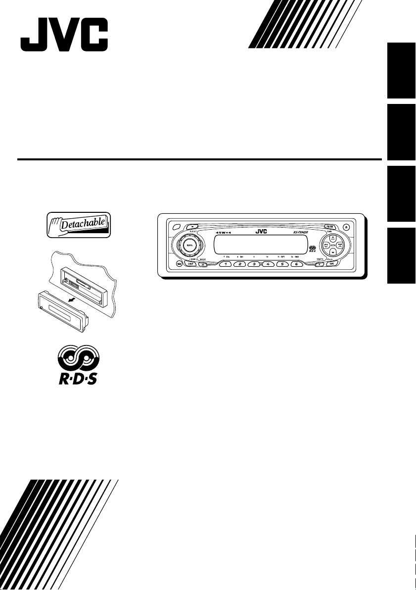
CASSETTE RECEIVER
CASSETTEN-RECEIVER
RADIOCASSETTE
RADIO/CASSETTESPELER
KS-FX842R
ENGLISH
DEUTSCH
FRANÇAIS
NEDERLANDS
For installation and connections, refer to the separate manual.
Für den Einbau und die Anschlüsse siehe das eigenständige Handbuch.
Pour l’installation et les raccordements, se référer au manuel séparé.
Bijzonderheden over de installatie en aansluiting van het apparaat vindt u in de
desbetreffende handleiding.
INSTRUCTIONS
BEDIENUNGSANLEITUNG
MANUEL D’INSTRUCTIONS
GEBRUIKSAANWIJZING
GET0140-001A
[E/EX]
Page 2
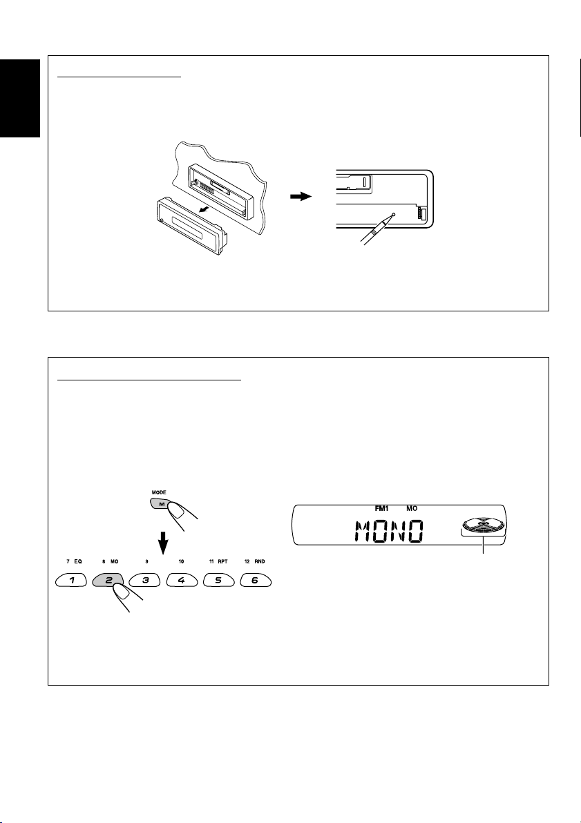
How to reset your unit
After detaching the control panel, press the reset button on the panel holder using a ball-point pen
or a similar tool.
This will reset the built-in microcomputer.
ENGLISH
Note:
Your preset adjustments—such as preset channels or sound adjustments—will also be erased.
How to use the M (MODE) button
If you press M (MODE), the unit goes into functions mode, then the number buttons work as
different function buttons.
• When connecting a JVC MP3-compatible CD changer: The 5/∞ buttons will also work as
+10/–10 buttons after pressing M (MODE).
Ex.: When number button 2 works as MO (monaural) button.
Time countdown indicator
To use these buttons for original functions again after pressing M (MODE), wait for 5 seconds
without pressing any of these buttons until the functions mode is cleared.
• Pressing M (MODE) again also clears the functions mode.
2
Page 3

Thank you for purchasing a JVC product. Please read all instructions carefully before operation,
to ensure your complete understanding and to obtain the best possible performance from the unit.
CONTENTS
How to reset your unit ............................... 2
How to use the M (MODE) button ............. 2
LOCATION OF THE BUTTONS ............ 4
Control panel ............................................. 4
BASIC OPERATIONS ....................... 5
Turning on the power ................................ 5
Setting the clock ........................................ 6
RADIO OPERATIONS ...................... 7
Listening to the radio ................................. 7
Storing stations in memory ....................... 9
Tuning in to a preset station ...................... 10
RDS OPERATIONS ......................... 11
What you can do with RDS ....................... 11
Other convenient RDS functions and
adjustments ............................................ 15
TAPE OPERATIONS ........................ 18
Listening to a cassette .............................. 18
Finding the beginning of a tune ................. 19
Other convenient tape functions ............... 19
Prohibiting cassette ejection ..................... 20
SOUND ADJUSTMENTS ................... 21
Selecting preset sound modes
(C-EQ: custom equalizer) ....................... 21
Adjusting the sound .................................. 22
OTHER MAIN FUNCTIONS ................ 23
Changing the general settings (PSM) ....... 23
Detaching the control panel ...................... 26
CD CHANGER OPERATIONS .............. 27
Playing discs ............................................. 27
Selecting the playback modes .................. 30
EXTERNAL COMPONENT OPERATIONS ... 31
Playing an external component ................. 31
DAB TUNER OPERATIONS ................ 32
Tuning in to an ensemble and one of the
services .................................................. 32
Storing DAB services in memory .............. 33
Tuning in to a preset DAB service ............. 34
What you can do more with DAB .............. 35
USING THE REMOTE CONTROLLER ..... 36
Location of the buttons .............................. 37
TROUBLESHOOTING ...................... 38
MAINTENANCE ............................. 40
SPECIFICATIONS........................... 41
ENGLISH
Note:
For security reasons, a numbered ID card is provided with this unit, and the same ID number is imprinted on
the unit’s chassis. Keep the card in a safe place, as it will help the authorities to identify your unit if stolen.
BEFORE USE
*
For safety....
• Do not raise the volume level too much, as this will
block outside sounds, making driving dangerous.
• Stop the car before performing any complicated
operations.
*
Temperature inside the car....
If you have parked the car for a long time in hot or
cold weather, wait until the temperature in the car
becomes normal before operating the unit.
3
Page 4
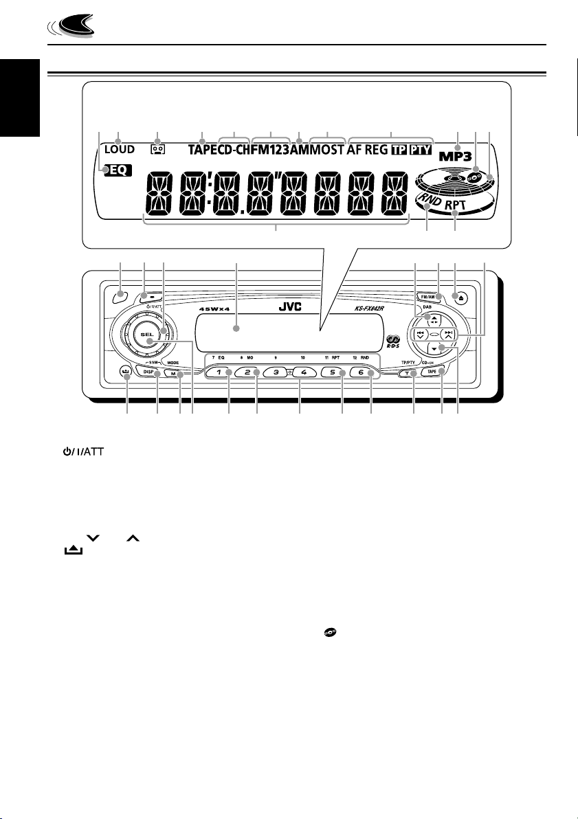
LOCATION OF THE BUTTONS
Control panel
Display window
ENGLISH
s
a
d
f
3
q
p
9
1 Remote sensor
2 (standby/on/attenuator) button
3 Control dial
4 Display window
5 5 (up) button
23 (tape direction) button
6 FM/AM (DAB) button
7 0 (eject) button
8 4 /¢ buttons
9 (control panel release) button
p DISP (display) button
• Also functions as SSM buttons when pressed
together with M (MODE) button.
q M (MODE) button
• Also functions as SSM buttons when pressed
together with DISP (display) button.
w SEL (select) button
e EQ (equalizer) button
r MO (monaural) button
t Number buttons
y RPT (repeat) button
u RND (random) button
• Functions only when connecting to a CD changer.
i T (TP/PTY: traffic programme/programme
type) button
o TAPE (CD-CH: CD changer) button
; ∞ (down) button
e
hg
j
k
c
41 2
r
t
y
l /
u
i
v b
6
75
o
z
x
8
;w
Display window
a EQ (equalizer) indicator
s LOUD (loudness) indicator
d Tape–in indicator
f TAPE indicator
g CD-CH (CD changer) indicator
h FM band indicators (FM1, FM2, FM3)
j AM band indicator
k Tuner reception indicators
MO (monaural), ST (stereo)
l RDS indicators
AF, REG, TP, PTY
/ MP3 indicator
• Lights up only when playing an MP3 disc on a
JVC MP3-compatible CD changer.
z (disc) indicator
• Lights up only when connecting to a CD changer.
x Volume (or audio) level indicator
c Main display
v RND (random) indicator
• Lights up only when connecting to a CD changer.
b RPT (repeat) indicator
4
Page 5
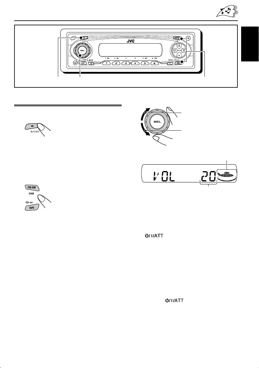
BASIC OPERATIONS
ENGLISH
1
3
Turning on the power
1
Turn on the power.
Note on One-Touch Operation:
When you select a source in step 2 below, the
power automatically comes on. You do not have
to press this button to turn on the power.
2
Select the source.
To operate the tuner (FM or AM),
see pages 7 – 17.
To play a tape,
see pages 18 – 20.
To operate the CD changer,
see pages 27 – 30.
To operate the external component
(LINE IN), see page 31.
To operate the DAB tuner,
see pages 32 – 35.
2
3
Adjust the volume.
To increase the volume
To decrease the volume
Volume (or audio) level indicator
(see page 25)
Volume level appears.
4
Adjust the sound as you want. (See
pages 21 and 22.)
To drop the volume in a moment
Press briefly while listening to any
source. “AT T” starts flashing on the display, and
the volume level will drop in a moment.
To resume the previous volume level, press the
button briefly again.
• If you turn the control dial, you can also restore
the sound.
To turn off the power
Press and hold for more than one
second.
“SEE YOU” appears, then the unit turns off.
5
Page 6
ENGLISH
Frequency
Clock
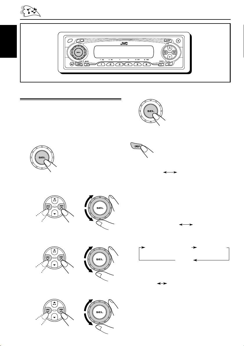
Setting the clock
You can also set the clock system to either
24 hours or 12 hours.
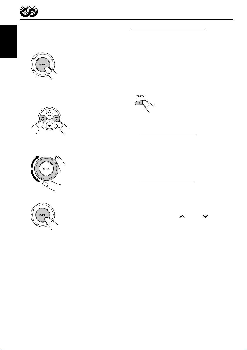
1
Press and hold SEL (select) for more
than 2 seconds so that one of the
PSM items appears on the display.
(PSM: see page 24.)
2
Set the hour.
1 Select “CLOCK H” (hour) if not shown on
the display.
2 Adjust the hour.
12
3
Set the minute.
1 Select “CLOCK M” (minute).
2 Adjust the minute.
12
5
Finish the setting.
To check the current clock time or change the
display mode
• During tuner operation:
Notes:
• For the indication change during RDS operation,
see page 16.
• For the indication change during DAB operation,
see page 33.
• During tape operation:
• During CD changer operation:
Press DISP (display) repeatedly.
Each time you press the button, the
display mode changes as follows:
Play mode (TAPE)
Elapsed playing time
Clock
Clock
Disc number
4
6
Set the clock system.
1 Select “24H/12H.”
2 Select “24H” or “12H.”
12
• During external component operation:
ClockLINE IN
• During power off:
The power turns on and the clock time is
shown for 5 seconds, then the power turns off.
Page 7
RADIO OPERATIONS
ENGLISH
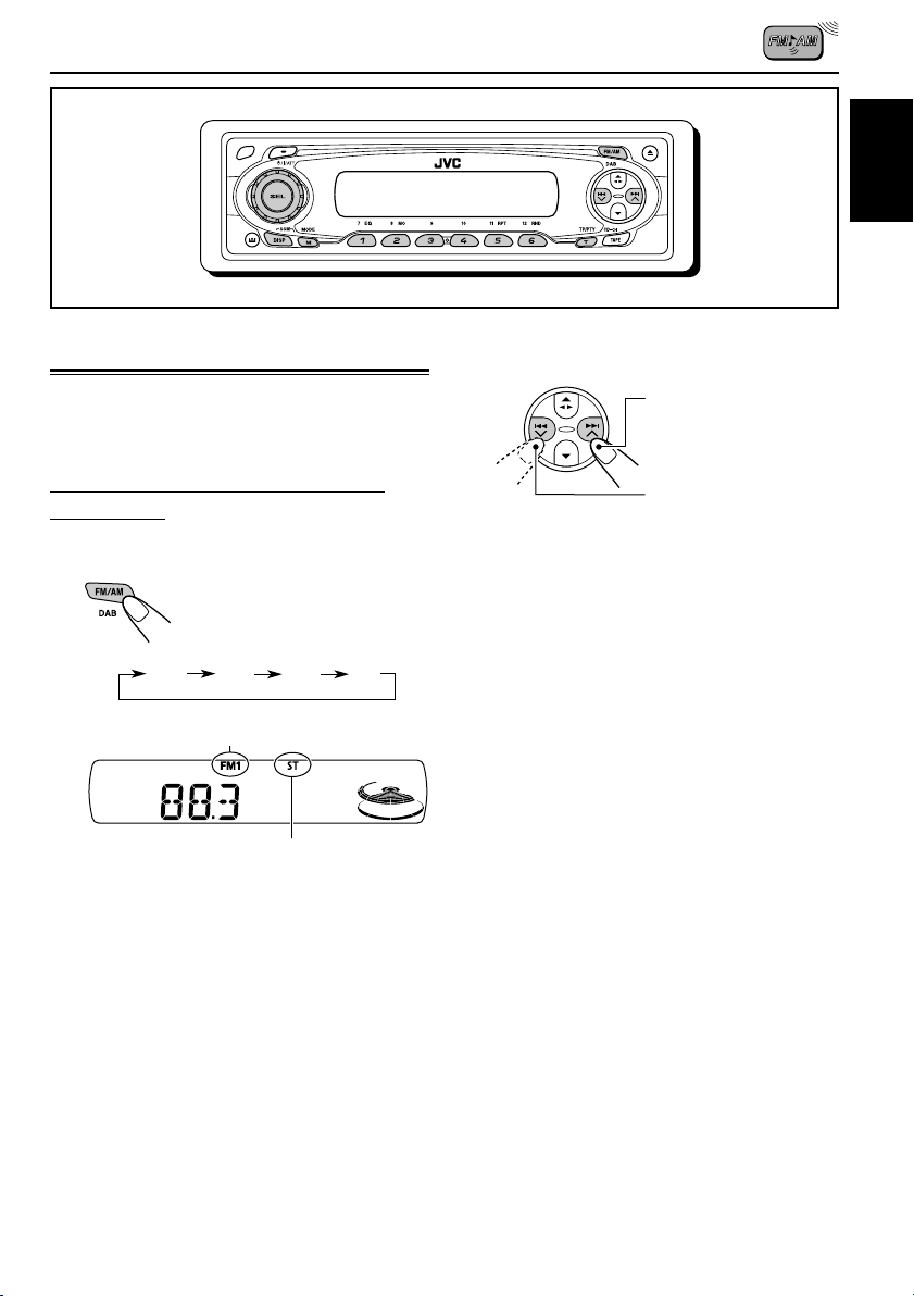
Listening to the radio
You can use either automatic searching or
manual searching to tune in to a particular
station.
Searching a station automatically:
Auto search
1
Select the band (FM1 – 3, AM).
Each time you press the
button, the band changes as
follows:
FM1 FM2 FM3 AM
Selected band appears.
Lights up when receiving an FM stereo
broadcast with sufficient signal strength.
Note:
This receiver has three FM bands (FM1, FM2,
FM3). You can use any one of them to listen to
an FM broadcast.
2
Start searching a station.
To search stations of
higher frequencies
To search stations of
lower frequencies
When a station is received, searching stops.
To stop searching before a station is
received, press the same button you have
pressed for searching.
7
Page 8
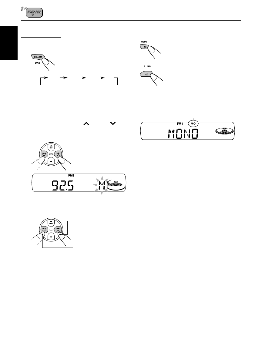
Searching a station manually:
Manual search
1
ENGLISH
Select the band (FM1 – 3, AM).
Each time you press the
button, the band changes as
follows:
FM1 FM2 FM3 AM
Note:
This receiver has three FM bands (FM1, FM2,
FM3). You can use any one of them to listen to
an FM broadcast.
2
Press and hold ¢ or 4
until “M” (manual) starts flashing on
the display.
When an FM stereo broadcast is hard to
receive:
1 Press M (MODE) to enter the
functions mode while listening
to an FM stereo broadcast.
2 Press MO (monaural), while
still in the functions mode, so
that the MO indicator lights up
on the display.
Each time you press the
button, the MO indicator lights
up and goes off alternately.
MO (monaural) indicator
When the MO indicator is lit on the display, the
sound you hear becomes monaural but the
reception will be improved.
3
Tune in to a station you want while
“M” (manual) is flashing.
To tune in to stations of
higher frequencies
To tune in to stations of
lower frequencies
• If you release your finger from the button,
the manual mode automatically turns off
after 5 seconds.
• If you hold down the button, the frequency
keeps changing (in 50 kHz intervals for FM
and 9 kHz intervals for AM—MW/LW) until
you release the button.
8
Page 9
Storing stations in memory
You can use one of the following two methods to
store broadcasting stations in memory.
• Automatic preset of FM stations: SSM (Strongstation Sequential Memory)
• Manual preset of both FM and AM stations
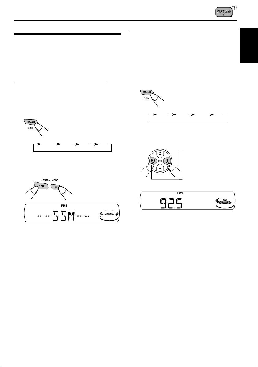
FM station automatic preset: SSM
You can preset 6 local FM stations in each FM
band (FM1, FM2, and FM3).
1
Select the FM band (FM1 – 3) you
want to store FM stations into.
Each time you press the
button, the band changes as
follows:
FM1 FM2 FM3 AM
2
Press and hold both buttons for
more than 2 seconds.
Manual preset
You can preset up to 6 stations in each band
(FM1, FM2, FM3, and AM) manually.
Ex.: Storing FM station of 92.5 MHz into the
preset number 1 of the FM1 band.
1
Select the band (FM1 – 3, AM) you
want to store stations into (in this
example, FM1).
Each time you press the
button, the band changes as
follows:
FM1 FM2 FM3 AM
2
Tune in to a station (in this example,
of 92.5 MHz).
To tune in to stations of
higher frequencies
To tune in to stations of
lower frequencies
ENGLISH
“- -SSM- -” appears, then disappears when
automatic preset is over.
Local FM stations with the strongest signals are
searched and stored automatically in the band
number you have selected (FM1, FM2, or FM3).
These stations are preset in the number
buttons—No.1 (lowest frequency) to No.6
(highest frequency).
When automatic preset is over, the station stored
in number button 1 will be automatically tuned in.
CONTINUED ON THE NEXT PAGE
9
Page 10
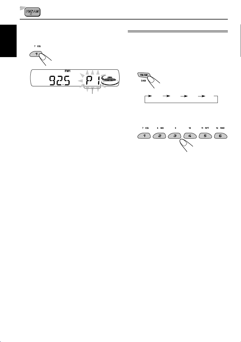
3
Press and hold the number button
(in this example, 1) for more than
2 seconds.
ENGLISH
Tuning in to a preset station
You can easily tune in to a preset station.
Remember that you must store stations first. If
you have not stored them yet, see “Storing
stations in memory” on pages 9 and 10.
1
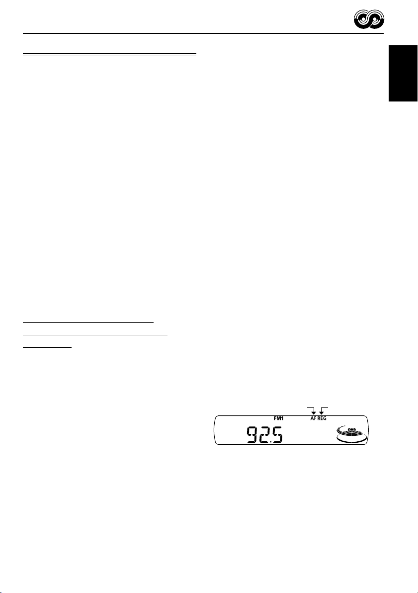
Select the band (FM1 – 3, AM).
Each time you press the
button, the band changes as
follows:
“P1” flashes for a few seconds.
4
Repeat the above procedure to store
other stations into other preset
numbers.
Notes:
• A previously preset station is erased when a new
station is stored in the same preset number.
• Preset stations are erased when the power supply to
the memory circuit is interrupted (for example,
during battery replacement). If this occurs, preset
the stations again.
FM1 FM2 FM3 AM
2
Select the number (1 – 6) for the
preset station you want.
10
Page 11
RDS OPERATIONS
What you can do with RDS
RDS (Radio Data System) allows FM stations to
send an additional signal along with their regular
programme signals. For example, the stations
send their station names, as well as information
about what type of programme they broadcast,
such as sports or music, etc.
Another advantage of RDS function is called
“Enhanced Other Networks.” By using the
Enhanced Other Networks data sent from a
station, you can tune in to a different station of a
different network broadcasting your favorite
programme or traffic announcement while
listening to another programme or to another
source such as tape.
By receiving the RDS data, this unit can do the
following:
• Tracing the same programme automatically
(Network-Tracking Reception)
• Standby Reception of TA (Traffic
Announcement) or your favorite programme
• PTY (Programme Type) search
• Programme search
• And some other functions
Tracing the same programme
automatically (Network-Tracking
Reception)
When driving in an area where FM reception is
not good, the tuner built in this unit automatically
tunes in to another RDS station, broadcasting the
same programme with stronger signals. So, you
can continue to listen to the same programme in
its finest reception, no matter where you drive.
(See the illustration on page 17.)
Two types of the RDS data are used to make
Network-Tracking Reception work correctly
—PI (Programme Identification) and AF
(Alternative Frequency).
Without receiving these data correctly from the
RDS station you are listening to, NetworkTracking Reception will not operate.
To use Network-Tracking Reception
You can select the different modes of networktracking reception to continue listening to the
same programme in its finest reception.
When shipped from the factory, “AF” is selected.
• AF: Network-Tracking Reception is
activated with Regionalization set to
“off.”
With this setting, the unit switches to
another station within the same
network when the receiving signals
from the current station become
weak. (In this mode, the programme
may differ from the one currently
received.)
The AF indicator lights up but the
REG indicator does not.
• AF REG: Network-Tracking Reception is
activated with Regionalization set to
“on.”
With this setting, the unit switches to
another station, within the same
network, broadcasting the same
programme when the receiving
signals from the current station
become weak.
Both the AF indicator and the REG
indicator light up.
• OFF: Network-Tracking Reception is
deactivated.
Neither the AF indicator nor the REG
indicator lights up.
AF indicator REG indicator
Note:
If a DAB tuner is connected and Alternative Reception
(for DAB services) is activated, Network-Tracking
Reception (“AF”) is also activated automatically. On
the other hand, Network-Tracking Reception cannot
be deactivated without deactivating Alternative
Reception. (See page 35.)
ENGLISH
11
Page 12
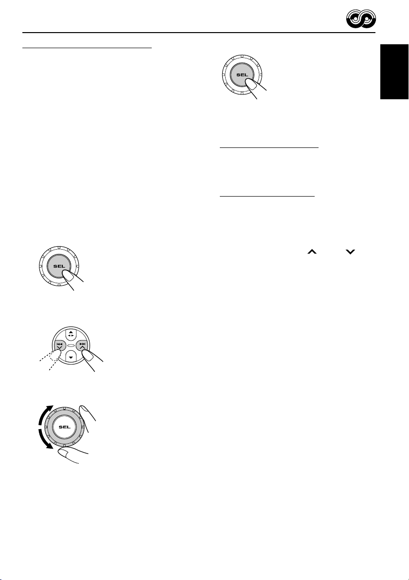
1
Press and hold SEL (select) for more
than 2 seconds so that one of the
PSM items appears on the display.
(PSM: see page 24.)
ENGLISH
2
Select “AF-REG” (alternative
frequency/regionalization reception)
if not shown on the display.
3
Select the desired mode—“AF,”
“AF REG,” or “OFF.”
4
Finish the setting.
Using TA Standby Reception
TA Standby Reception allows the unit to switch
temporarily to Traffic Announcement (TA) from
the current source (another FM station, tape, or
other connected components).
• TA Standby Reception will not work if you are
listening to an AM station.
Press T (TP/PTY) to activate TA Standby
Reception.
7 When the current source is FM, the TP
indicator either lights up or flashes.
• If the TP indicator lights up, TA Standby
Reception is activated.
If a station starts broadcasting a traffic
announcement, “TRAFFIC” appears on the
display, and this unit automatically tunes in to
the station. The volume changes to the
preset TA volume level (see page 16) and the
traffic announcement can be heard.
• If the TP indicator flashes, TA Standby
Reception is not yet activated since the
station being received does not provide the
signals used for TA Standby Reception.
To activate TA Standby Reception, you need
to tune in to another station providing these
signals. Press ¢ or 4 to search
for such a station.
When a station providing these signals is
tuned in, the TP indicator stops flashing and
remains lit. Now TA Standby Reception is
activated.
7 When the current source is other than FM,
the TP indicator lights up.
If a station starts broadcasting a traffic
announcement, “TRAFFIC” appears on the
display, and this unit automatically changes the
source and tunes in to the station.
12
To deactivate the TA Standby Reception,
press T (TP/PTY) again. The TP indicator goes
off.
Page 13
Using PTY Standby Reception
PTY Standby Reception allows the unit to switch
temporarily to your favorite programme (PTY:
Programme Type) from the current source
(another FM station, tape, or other connected
components).
4
Finish the setting.
ENGLISH
• PTY Standby Reception will not work if you are
listening to an AM station.
You can select your favorite programme type for
PTY Standby Reception.
When shipped from the factory, PTY Standby
Reception is turned off. (“OFF” is selected for
PTY Standby Reception.)
1
Press and hold SEL (select) for more
than 2 seconds so that one of the
PSM items appears on the display.
(PSM: see page 24.)
2
Select “PTY STBY” (standby) if not
shown on the display.
3
Select one of the twenty-nine PTY
codes. (See page 17.)
Selected code name
appears on the display
and is stored into memory.
7 When the current source is FM, the PTY
indicator either lights up or flashes.
• If the PTY indicator lights up, PTY Standby
Reception is activated.
If a station starts broadcasting the selected
PTY programme, this unit automatically
tunes in to the station.
• If the PTY indicator flashes, PTY Standby
Reception is not yet activated since the
station being received does not provide the
signals used for PTY Standby Reception.
To activate PTY Standby Reception, you
need to tune in to another station providing
these signals. Press ¢ or 4 to
search for such a station.
When a station providing these signals is
tuned in, the PTY indicator stops flashing
and remains lit. Now PTY Standby Reception
is activated.
7 When the current source is other than FM,
the PTY indicator lights up.
If a station starts broadcasting the selected
PTY programme, this unit automatically
changes the source and tunes in to the station.
To deactivate the PTY Standby Reception,
select “OFF” in step 3 on the left column. The
PTY indicator goes off.
13
Page 14
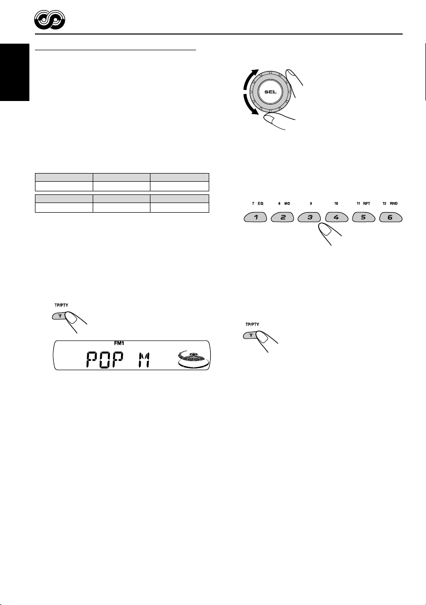
Searching your favorite programme
You can search any one of the PTY codes.
In addition, you can store your 6 favorite
programme types in the number buttons.
ENGLISH
When shipped from the factory, the following
6 programme types have been stored in the
number buttons (1 to 6).
To store your favorite programme types, see
below.
To search your favorite programme type, see
page 15.
1
POP M
45
CLASSICS
To store your favorite programme types
1
Press and hold T (TP/PTY) for more
than 2 seconds while listening to an
FM station.
2
ROCK M EASY M
AFFAIRS
VARIED
2
Select one of the twenty-nine PTY
codes. (See page 17.)
Selected code name
appears on the display.
3
Press and hold the number button
for more than 2 seconds to store the
3
PTY code selected into the preset
number you want.
6
“MEMORY” and the selected code name will
flash alternately.
4
Press and hold T (TP/PTY) for more
than 2 seconds to exit from this
mode.
14
The last selected PTY code appears.
Page 15

To search your favorite programme type
1
Press and hold T (TP/PTY) for more
than 2 seconds while listening to an
FM station.
• If there is a station broadcasting a programme
of the same PTY code as you selected, that
station is tuned in.
• If there is no station broadcasting a
programme of the same PTY code as you
selected, the station will not change.
Note:
In some areas, the PTY search will not work correctly.
ENGLISH
The last selected PTY code appears.
2
To select one of your favorite
programme type
or
To select any one of the twenty-nine
PTY codes
Ex.: When “ROCK M” is selected
3
Press ¢ or 4 to start PTY
search for your favorite programme.
Other convenient RDS
functions and adjustments
Automatic selection of the station
when using the number buttons
Usually when you press the number button, the
preset station is tuned in.
However, when the preset station is an RDS
station, something different will happen. If the
signals from that preset station are not sufficient
for good reception, this unit, using the AF data,
tunes in to another frequency broadcasting the
same programme as the original preset station is
broadcasting. (Programme search)
• The unit takes some time to tune in to another
station using programme search.
To activate programme search, follow the
procedure below.
• See also “Changing the general settings
(PSM)” on page 23.
1 Press and hold SEL (select) for more than
2 seconds so that one of the PSM items
appears on the display.
2 Press ¢ or 4 to select
“P(Programme)-SEARCH.”
3 Turn the control dial clockwise to select “ON.”
Now programme search is activated.
4 Press SEL (select) to finish the setting.
To cancel programme search, repeat the same
procedure and select “OFF” in step 3 by turning
the control dial counterclockwise.
15
Page 16

Changing the display mode while
listening to an FM station
You can change the initial indication on the
display to station name (PS NAME), station
ENGLISH
frequency (FREQ), or clock time (CLOCK) while
listening to an FM RDS station.
• See also “Changing the general settings
(PSM)” on page 23.
1 Press and hold SEL (select) for more than
2 seconds so that one of the PSM items
appears on the display.
2 Press ¢ or 4 to select
“DISPMODE” (display mode).
3 Turn the control dial to set to the desired
indication (“PS NAME,” “FREQ,” or “CLOCK”).
4 Press SEL (select) to finish the setting.
Setting the TA volume level
You can preset the volume level for TA Standby
Reception. When a traffic programme is received,
the volume level automatically changes to the
preset level.
• See also “Changing the general settings
(PSM)” on page 23.
1 Press and hold SEL (select) for more than
2 seconds so that one of the PSM items
appears on the display.
2 Press ¢ or 4 to select “TA VO L”
(TA volume).
3 Turn the control dial to set to the desired
volume.
You can set it from “VOL 00” to “VOL 50.”
4 Press SEL (select) to finish the setting.
Note:
By pressing DISP (display), you can change the
display while listening to an FM RDS station only.
Each time you press the button, the following
information appears on the display:
Station name
(PS NAME)
Station frequency
(FREQ)
Programme type
(PTY)
Clock
(CLOCK)
• Then, the display goes back to the original
indication in several seconds.
Automatic clock adjustment
When shipped from the factory, the clock built in
this unit is set to be readjusted automatically
using the CT (Clock Time) data in the RDS
signal.
If you do not want to use automatic clock
adjustment, follow the procedure below.
• See also “Changing the general settings
(PSM)” on page 23.
1 Press and hold SEL (select) for more than
2 seconds so that one of the PSM items
appears on the display.
2 Press ¢ or 4 to select “AUTO
ADJ” (adjustment).
3 Turn the control dial counterclockwise to select
“OFF.”
Now automatic clock adjustment is canceled.
4 Press SEL (select) to finish the setting.
To reactivate clock adjustment, repeat the
same procedure and select “ON” in step 3 by
turning the control dial clockwise.
Note:
You must stay tuned to the same station for more than
2 minutes after setting “AUTO ADJ” to “ON.”
Otherwise, the clock time will not be adjusted. (This is
because the unit takes up to 2 minutes to capture the
CT data in the RDS signal.)
16
Page 17

PTY codes
NEWS: News
AFFAIRS: Topical programmes expanding
on current news or affairs
INFO: Programmes which impart
advice on a wide variety of topics
SPORT: Sport events
EDUCATE: Educational programmes
DRAMA: Radio plays
CULTURE: Programmes on national or
regional culture
SCIENCE: Programmes on natural science
and technology
VARIED: Other programmes like comedies
or ceremonies
POP M: Pop music
ROCK M: Rock music
EASY M: Easy-listening music
LIGHT M: Light music
CLASSICS: Classical music
OTHER M: Other music
WEATHER: Weather information
FINANCE: Reports on commerce, trading,
the Stock Market, etc.
CHILDREN: Entertainment programmes for
children
SOCIAL: Programmes on social
activities
RELIGION: Programmes dealing with any
aspect of belief or faith, or the
nature of existence or ethics
PHONE IN: Programmes where people can
express their views either by
phone or in a public forum
TRAVEL: Programmes about travel
destinations, package tours,
and travel ideas and
opportunities
LEISURE: Programmes concerned with
recreational activities such as
gardening, cooking, fishing,
etc.
JAZZ: Jazz music
COUNTRY: Country music
NATION M: Current popular music from
another nation or region, in that
country’s language
OLDIES: Classic pop music
FOLK M: Folk music
DOCUMENT: Programmes dealing with
factual matters, presented in an
investigative style
ENGLISH
The same programme can be received on different frequencies.
Programme 1
broadcasting on
frequency A
Programme 1
broadcasting on
frequency B
Programme 1
broadcasting on
frequency C
Programme 1
broadcasting on
frequency E
Programme 1
broadcasting on
frequency D
17
Page 18

ENGLISH
TAPE OPERATIONS
Listening to a cassette
You can play back type I (normal) tapes.
1
Open the control panel.
Note on One-Touch Operation:
When a cassette is already in the cassette
compartment, pressing TAPE (CD-CH) turns on
the unit and starts tape play automatically.
2
Insert a cassette into the cassette
compartment.
The unit turns on and
tape play starts
automatically.
3
Close the control panel by hand.
To stop play and eject the cassette
Press 0.
Tape play stops, the control panel flips down. The
cassette automatically ejects from the cassette
compartment. The source changes to the
previously selected one.
If you change the source, tape play also stops
(without ejecting the cassette this time).
• You can also eject the cassette by pressing 0
while the unit is turned off.
To fast-forward and rewind a tape
Press and hold ¢ for
more than one second to
fast-forward the tape.
When the tape reaches its
end, the tape is reversed and
playback starts from the
beginning of the other side.
Press and hold 4 for more than one
second to rewind the tape.
When the tape reaches its end, playback of the
same side starts.
To stop fast-forward and rewind at any
position on the tape, press 23.
Tape play starts from that position on the tape.
18
4
Select the tape direction.
Each time you press 23,
the tape direction changes
alternately between forward
( ) and reverse
( ).
Notes:
• When one side of the tape reaches its end during
play, the other side of the tape automatically starts
playing. (Auto Reverse)
• When the tape reaches its end while fastforwarding, the tape direction will be changed
automatically.
Page 19

Finding the beginning of a
tune
Multi Music Scan (MMS) allows you to
automatically start playback from the beginning
of a specified tune. You can specify up to 9 tunes
ahead of or before the current tune.
During playback
Specify the tune you want to locate (how
many tunes ahead of or before the
current tune).
Press ¢ to locate a
tune ahead of the current
tune on the cassette.
Press 4 to locate a
tune before the current tune
on the cassette.
Ex.: When you locate three tunes ahead
of the current tune
Each time you press the buttons, the number
changes up to ±9.
When the beginning of the specified tune is
located, playback starts automatically.
Notes:
• While locating a specified tune:
– If the tape is rewound to its beginning, playback
starts from the beginning of that side.
– If the tape is fast-forwarded to the end, it is
reversed and played from the beginning of the
other side.
• In the following cases, the Multi Music Scan
function may not operate correctly:
– Tapes with tunes having long pianissimo
passages (very quiet parts) or non-recorded
portions between tunes.
– Tapes with short non-recorded sections.
– Tapes with high level of noise or humming
between tunes.
– Tapes with tunes recorded at low recording
levels.
Other convenient tape functions
Skipping the blank portions on the tape
You can skip blank portions between the tunes
(Blank Skip).
When this function is turned on, the unit fastforwards (skipping blank portions of 15 seconds
or more), to the next tune and starts playback.
• See also “Changing the general settings
(PSM)” on page 23.
1
Press and hold SEL (select) for more
than 2 seconds so that one of the
PSM items appears on the display.
(PSM: see page 24.)
2
Press ¢ or 4 to select
“B.SKIP” (blank skip).
3
Turn the control dial clockwise to
select “ON.”
Now Blank Skip is
activated.
4
Finish the setting.
To cancel Blank Skip, repeat the same procedure
and select “OFF” in step 3 by turning the control
dial counterclockwise.
ENGLISH
19
Page 20

Playing the current tune repeatedly
You can play the current tune repeatedly
(Repeat Play).
ENGLISH
Lights up when Repeat Play is turned on.
1 Press M (MODE) to enter the
functions mode while playing a
tune you want to hear over again
on a cassette.
2 Press RPT (repeat), while still in
the functions mode, so that
“REPEAT” appears on the
display.
Prohibiting cassette ejection
You can prohibit cassette ejection and lock a
cassette in the cassette compartment.
While pressing TAPE (CD-CH), press and
hold for more than 2 seconds.
“NO EJECT” flashes on the display for about
5 seconds, and the cassette is locked and
cannot be ejected.
When the tune has been played, the tape is
automatically rewound to the beginning of that
tune and the same tune will be played again.
To cancel Repeat Play, repeat steps 1 and 2
again so that the RPT indicator goes off.
Note:
In the following cases, Blank Skip and Repeat Play
may not operate correctly:
– Tapes with tunes having long pianissimo passages
(very quiet parts) or non-recorded portions during
tunes.
– Tapes with short non-recorded sections.
– Tapes with high level noise or humming between
tunes.
– Tapes with tunes recorded at low recording levels.
To cancel the prohibition and unlock the
cassette
While pressing TAPE (CD-CH), press and hold
again for more than 2 seconds.
“EJECT OK” flashes on the display for about
5 seconds, and the cassette is unlocked.
Note:
If you press 0 while cassette ejection is prohibited,
the control panel flips down, but the cassette
continues to play and cannot be ejected.
20
Page 21

SOUND ADJUSTMENTS
Selecting preset sound modes
(C-EQ: custom equalizer)
You can select a preset sound mode (C-EQ:
custom equalizer) suitable to the music genre.
• There is a time limit in doing the following
procedure. If the setting is canceled before you
finish, start from step 1 again.
1
Press M (MODE) to enter the
functions mode.
2
Press EQ (equalizer), while still in
the functions mode.
The last selected sound
mode is recalled and applied
to the current source.
Ex.: If you have selected “USER” previously
Indication For: Preset values
BAS TRE LOUD
USER (Flat sound) 00 00 OFF
ROCK Rock or +03 +01 ON
disco music
CLASSIC Classical +01 –02 OFF
music
POPS Light music +04 +01 OFF
HIP HOP Funk or rap +02 00 ON
music
JAZZ Jazz music +02 +03 OFF
Note:
You can adjust each sound mode to your preference.
Once you make an adjustment, it is automatically
stored for the currently selected sound mode. See
“Adjusting the sound” on page 22.
ENGLISH
3
Select the sound mode you want.
Each time you press the
button, the sound modes
change as follows:
USER
The EQ indicator lights up when any sound
mode other than “USER” is selected.
Ex.: When you select “ROCK”
ROCK
CLASSIC
POPSHIP HOPJAZZ
21
Page 22

Adjusting the sound
2
Adjust the setting.
You can adjust the sound characteristics to your
preference.
ENGLISH
1
Select the item you want to adjust.
Each time you press the
button, the adjustable items
change as follows:
BAS
(bass)
VOL
(volume)
Indication To do: Range
1
BAS*
TRE*
FAD*
BAL Adjust the left L06 (Left only)
LOUD*1Boost low and high
VOL*
Adjust the bass. –06 (min.)
1
Adjust the treble. –06 (min.)
2
Adjust the front R06 (Rear only)
and rear speaker |
balance. F06 (Front only)
and right speaker |
balance. R06 (Right only)
frequencies to LOUD ON
produce a well- |
balanced sound LOUD OFF
at low volume level.
3
Adjust the volume. 00 (min.)
TRE
(treble)
LOUD
(loudness)
(balance)
|
+06 (max.)
|
+06 (max.)
|
50 (max.)
FAD
(fader)
BAL
To increase the level or
turn on the loudness
To decrease the level or
turn off the loudness
Equalization pattern changes
as you adjust the bass or treble.
Ex. 1: When you adjust “TRE” (treble)
Ex. 2: When you turn on the loudness
3
Repeat steps 1 and 2 to adjust the
other items.
To reset each sound mode to the factory
settings, repeat the same procedure and
reassign the preset values listed in the table on
page 21.
*1When you adjust the bass, treble, or loudness, the
adjustment you have made is stored for the
currently selected sound mode (C-EQ) including
“USER.”
*2If you are using a two-speaker system, set the fader
level to “00.”
*3Normally the control dial works as the volume
control. So you do not have to select “VOL” to
adjust the volume level.
22
Page 23

OTHER MAIN FUNCTIONS
Changing the general settings
(PSM)
You can change the items listed on the next page
by using the PSM (Preferred Setting Mode)
control.
Basic Procedure
1
Press and hold SEL (select) for more
than 2 seconds so that one of the
PSM items appears on the display.
(See page 24.)
2
Select the PSM item you want to
adjust.
3
Adjust the PSM item selected.
Ex.: When you select “AUDIO 2”
4
Repeat steps 2 and 3 to adjust the
other PSM items if necessary.
5
Finish the setting.
ENGLISH
Ex.: When you select “LEVEL”
23
Page 24

Preferred Setting Mode (PSM) items
• For detailed operations of each PSM items, refer to the pages listed in the table.
ENGLISH
Indications Selectable values/items
CLOCK H Hour adjustment
CLOCK M Minute adjustment
24H/12H 24/12-hour time display
AUTO ADJ Automatic clock setting
DISPMODE Display mode
CH DISP Changer display
AF-REG Alternative frequency/
Regionalization reception
PTY STBY PTY standby
TA VOL Traffic announcement
volume
P-SEARCH Programme search
DAB AF*2Alternative frequency
search
0 – 23 (1 – 12)
00 – 59
12H 24H
OFF ON
PS NAME FREQ
CLOCK
TIME DISC
AF AF REG
1
OFF*
OFF
29 programme types
(see page 17)
VOL 00 – VOL 50 VOL 20
OFF ON
AF OFF AF ON
Factory-preset See
settings page
0 (0:00)
6
00 (0:00) 6
24H
ON
PS NAME
DISC
AF
OFF
6
16
16
25
11, 12
13
16
OFF
AF ON
15
35
DAB VOL*2DAB volume adjustment
LEVEL Level display
VOL –12 VOL 12
AUDIO 1 AUDIO 2
OFF
TEL Telephone muting
MUTING 1 MUTING 2
OFF
B.SKIP Blank skip
3
EXT IN*
External component
OFF ON OFF 19
CHANGER LINE IN CHANGER 25
*1Displayed only when the “DAB AF” is set to “AF OFF.”
*2Displayed only when the DAB tuner is connected.
*3Displayed only when one of the following sources is selected—FM, AM, and TAPE.
24
VOL 00
AUDIO 2
OFF
35
25
25
Page 25

To set the changer display—CH DISP
This mode is used to check the display
information of the CD changer.
When shipped from the factory, “DISC” is
selected.
• DISC: Disc number and track number
appear.
• TIME: Elapsed playing time and track
number appear.
To select the level meter—LEVEL
You can select the level meter display according
to your preference.
When shipped from the factory, “AUDIO 2” is
selected.
• AUDIO 1: Shows the audio level indicator.
• AUDIO 2: Alternates “AUDIO 1” setting and
illumination display.
• OFF: Erases the audio level indicator.
To select the telephone muting—TEL
This mode is used when a cellular phone system
is connected. Depending on the phone system
used, select either “MUTING 1” or “MUTING 2”
whichever mutes the sounds from this unit.
When shipped from the factory, this mode is
deactivated.
• MUTING 1: Selects this if this setting can
mute the sounds while using the
cellular phone.
• MUTING 2: Selects this if this setting can
mute the sounds while using the
cellular phone.
• OFF: Cancels the telephone muting.
To select the external component to use
—EXT IN
You can connect the external component to the
CD changer jack on the rear using the Line Input
Adapter KS-U57 (not supplied).
To use the external component as the playback
source through this unit, you need to select
which component—CD changer or external
component—to use.
When shipped from the factory, CD changer is
selected as the external component.
ENGLISH
• CHANGER: To use the CD changer.
• LINE IN: To use the external component
other than CD changer.
Note:
For connecting the Line Input Adapter KS-U57 and
the external component, refer to the Installation/
Connection Manual (separate volume).
25
Page 26

Detaching the control panel
You can detach the control panel when leaving
the car.
When detaching or attaching the control panel,
ENGLISH
be careful not to damage the connectors on the
back of the control panel and on the panel
holder.
Detaching the control panel
Before detaching the control panel, be sure to
turn off the power.
1
Unlock the control panel.
2
Pull the control panel out of the unit.
Attaching the control panel
1
Insert the right side of the control
panel into the groove on the panel
holder.
2
Press the left side of the control
panel to fix it to the panel holder.
Note on cleaning the connectors:
If you frequently detach the control panel, the
connectors will deteriorate.
To minimize this possibility, periodically wipe the
connectors with a cotton swab or cloth moistened
with alcohol, being careful not to damage the
connectors.
26
3
Put the detached control panel into
the provided case.
Connectors
Page 27

CD CHANGER OPERATIONS
ENGLISH
We recommend that you use the JVC MP3compatible CD changer with your unit.
By using this CD changer, you can play back
your original CD-Rs (Recordable) and CD-RWs
(Rewritable) recorded either in audio CD format
or in MP3 format.
• You can also connect other CH-X series
CD changers (except CH-X99 and CH-X100).
However, they are not compatible with MP3
discs, so you cannot play back MP3 discs.
• You cannot use the KD-MK series CD
changers with this unit.
Before operating your CD changer:
• Refer also to the Instructions supplied with
your CD changer.
• If no discs are in the magazine of the CD
changer or the discs are inserted upside
down, “NO CD” will appear on the display. If
this happens, remove the magazine and set
the discs correctly.
• If no magazine is loaded in the CD changer,
“NO MAG” appears on the display. If this
happens, insert the magazine in the CD
changer.
• If “RESET 1” – “RESET 8” appears on the
display, something is wrong with the
connection between this unit and the CD
changer. If this happens, check the
connection and make sure the cords are
connected firmly. Then, press the reset
button of the CD changer.
Playing discs
Select the CD changer (CD-CH).
TAPE CD-CH*
* If you have not connected a CD changer, or if
you have changed the “EXT IN” setting to
“LINE IN” (see page 25), you cannot select the
CD changer.
• When the current disc is an MP3 disc:
Playback starts from the first folder of the
current disc once file check is completed.
MP3 indicator lights up.
Disc number
If you have selected “TIME” for “CH DISP” (see
page 25), the display changes as follows:
Folder number
Elapsed playing time File number
27
Page 28

• When the current disc is a CD:
Playback starts from the first track of the
current disc.
ENGLISH
Disc number Track number
If you have selected “TIME” for “CH DISP” (see
page 25), the display changes as follows:
Elapsed playing time Track number
Notes:
• When you press TAPE (CD-CH), the power
automatically comes on. You do not have to press
to turn on the power.
• If you change the source, CD changer play also
stops. Next time you select the CD changer as the
source, CD changer play starts from where
playback has been stopped previously.
To go to a particular disc directly
Press the number button corresponding to the
disc number to start its playback (while the
CD changer is playing).
To fast-forward or reverse the track/file
Press and hold ¢ ,
during play, to fast-forward
the track/file.
Press and hold 4 ,
during play, to reverse the
track/file.
Note:
During this operation on an MP3 disc, you can only
hear intermittent sounds. (The elapsed playing time
also changes intermittently on the display.)
To go to the next or previous tracks/files
Press ¢ briefly during
play, to skip ahead to the
beginning of the next track/
file.
Each time you press the
button consecutively, the
beginning of the next tracks/
files is located and played
back.
Press 4 briefly during play, to skip back to
the beginning of the current track/file.
Each time you press the button consecutively,
the beginning of the previous tracks/files is
located and played back.
• To select a disc number from 1 – 6:
Press 1 (7) – 6 (12) briefly.
• To select a disc number from 7 – 12:
Press and hold 1 (7) – 6 (12) for more than one
second.
28
Page 29

This operation is only possible when
using JVC MP3-compatible CD changer
(CH-X1500).
To go to a track/file quickly
1 Press M (MODE) to enter the functions mode
while playing a disc.
How to go to the desired track/file quickly
• Ex. 1: To select track/file number 32 while
playing track/file number 6
ENGLISH
(Three times) (Twice)
Track/file 6 \ 10 \ 20 \ 30 \ 31 \ 32
2 Press 5 (up) or ∞ (down) while still in the
functions mode.
To skip 10 tracks/files*
forwards to the last track/file
To skip 10 tracks/files*
backwards to the first track/file
* The first time you press 5 (up) or ∞ (down)
button, the track/file skips to the nearest
higher or lower track/file with a track/file
number of multiple ten (ex. 10th, 20th, 30th).
Then each time you press the button, you can
skip 10 tracks/files (see “How to go to the
desired track/file quickly” on the right column).
• After the last track/file, the first track/file will
be selected, and vice versa.
Note:
If the current playing disc is an MP3 disc, files are
skipped within the same folder.
• Ex. 2 :To select track/file number 8 while
playing track/file number 36
(Three times) (Twice)
Track/file 36 \ 30 \ 20 \ 10 \ 9 \ 8
To skip to the next or previous folder
(only for MP3 discs)
Press 5 (up) while playing an
MP3 disc, to go to the next
folder.
Each time you press the button
consecutively, the next folder is
located, and the first file in the
folder starts playback.
Press ∞ (down) while playing an MP3 disc, to go
to the previous folder.
Each time you press the button consecutively,
the previous folder is located, and the first file in
the folder starts playback.
29
Page 30

Selecting the playback modes
To play back tracks/files at random
(Disc Random/Magazine Random Play)
ENGLISH
Note:
The MP3 indicator also lights up if the current
playing disc is an MP3 disc.
Mode
DISC RND and RND All tracks/files of the
MAG RND RND indicator All tracks/files of the
1 Press M (MODE) to enter
the functions mode during
play.
2 Press RND (random), while
still in the functions mode, so
that “DISC RND” or
“MAG RND” appears on the
display.
Each time you press the
button, the random play mode
changes as follows:
DISC RND
MAG RND
Canceled
(disc) and RND indicators light up.
Ex.: When you select “DISC RND”
Active
indicator
indicators light current (or specified)
up. disc.
lights up. inserted discs.
Plays at random
To play back tracks/files repeatedly
(Track Repeat/Disc Repeat Play)
1 Press M (MODE) to enter
the functions mode during
play.
2 Press RPT (repeat), while still
in the functions mode, so that
“TRK RPT” or “DISC RPT”
appears on the display.
Each time you press the
button, the repeat play mode
changes as follows:
TRK RPT
Ex.: When you select “TRK RPT”
Note:
The MP3 indicator also lights up if the current
playing disc is an MP3 disc.
Mode
TRK RPT RPT indicator The current (or
DISC RPT and RPT All tracks/files of the
Active
indicator
lights up. specified) track/file.
indicators light current (or specified)
up. disc.
DISC RPT
Canceled
RPT indicator lights up.
Plays repeatedly
30
Page 31

EXTERNAL COMPONENT OPERATIONS
ENGLISH
Playing an external component
You can connect the external component to the
CD changer jack on the rear using the Line Input
Adapter KS-U57 (not supplied).
Preparations:
• For connecting the Line Input Adapter KS-U57 and
the external component, refer to the Installation/
Connection Manual (separate volume).
• Before operating the external component using the
following procedure, select the external input
correctly. See “To select the external component to
use—EXT IN” on page 25.
1
Select the external component
(LINE IN).
TAPE LINE IN
• If “LINE IN”* does not appear on the display,
see page 25 and select the external input
(“LINE IN”).
* Displayed only when one of the following sources is
selected—FM, AM, and TAPE.
2
Turn on the connected component
and start playing the source.
3
Adjust the volume.
4
Adjust the sound characteristics as
you want. (See pages 21 and 22.)
Note on One-Touch Operation:
When you press TAPE (CD-CH), the power
automatically comes on. You do not have to press
to turn on the power.
31
Page 32

ENGLISH
DAB TUNER OPERATIONS
We recommend that you use DAB (Digital Audio
Broadcasting) tuner KT-DB1500 or KT-DB1000
with your unit.
If you have another DAB tuner, consult your JVC
IN-CAR ENTERTAINMENT dealer.
• Refer also to the Instructions supplied with
your DAB tuner.
What is DAB system?
DAB is one of the digital radio broadcasting
systems available today. It can deliver CD
quality sound without any annoying
interference and signal distortion.
Furthermore, it can carry text, pictures, and
data.
In contrast to FM broadcast, where each
programme is transmitted on its own
frequency, DAB combines several
programmes (called “services”) to form one
“ensemble.”
In addition, each “service”—called “primary
service”—can also be divided into its
components (called “secondary service”).
With the DAB tuner connected with this unit,
you can enjoy these DAB services.
Tuning in to an ensemble and
one of the services
A typical ensemble has 6 or more programmes
(services) broadcast at the same time. After
tuning in to an ensemble, you can select a
service you want to listen to.
Before you start....
Press FM/AM (DAB) briefly if tape, CD changer,
or external component is the current source.
1
Select the DAB tuner.
Each time you press and
hold the button, the DAB
tuner and the FM/AM tuner
are alternately selected.
FM/AMDAB
2
Select the DAB band (DAB1, DAB2,
or DAB3).
Each time you press the
button, the DAB band
changes as follows:
DAB1 DAB2 DAB3
Note:
When reception switches between DAB and FM, the
listening volume level may increase or decrease
inconveniently. This change in the volume level results
from unequal audio injection levels at broadcaster
site, but not from the malfunction of this unit.
To prevent this inconvenience, you can adjust the DAB
volume level. (See “To adjust the DAB volume level”
on page 35.)
32
Note:
This receiver has three DAB bands (DAB1,
DAB2, DAB3). You can use any of them to tune
in to an ensemble.
Page 33

3
Start searching for an ensemble.
To search for ensembles
of higher frequency
To search for ensembles
of lower frequency
When an ensemble is received, searching
stops.
To stop searching before an ensemble is
received, press the same button you have
pressed for searching.
4
Select a service (either primary or
secondary) you want to listen to.
To select the next service
(If a primary service has
some secondary services,
they are selected before the
next primary service is
selected.)
To select the previous service (either
primary or secondary)
To change the display information while
tuning in to an ensemble
Normally service name is shown on the display.
If you want to check the ensemble name or its
frequency, press DISP (display).
Each time you press the button,
the following information appears
for a while on the display.
Service name
DAB band
To tune in to a particular ensemble
without searching
Before you start....
Press FM/AM (DAB) briefly if tape, CD changer,
or external component is the current source.
1 Press and hold FM/AM (DAB) to select DAB
tuner as the source.
2 Press FM/AM (DAB) repeatedly to select the
DAB band (DAB1, DAB2, or DAB3).
3 Press and hold ¢ or 4 for more
than one second. “MANU” (manual) appears
on the display.
4 Press ¢ or 4 repeatedly until the
ensemble you want is reached.
• If you hold down the button, the frequency
keeps changing until you release the button.
5 Press 5 (up) or ∞ (down) to select a service
(either primary or secondary) you want to
listen to.
To restore the FM/AM tuner
Press and hold FM/AM (DAB) again.
Storing DAB services in
memory
You can preset up to 6 DAB services in each
DAB band (DAB1, DAB2, and DAB3) manually.
Before you start....
Press FM/AM (DAB) briefly if tape, CD changer,
or external component is the current source.
1
Select the DAB tuner.
Each time you press and
hold the button, the DAB
tuner and the FM/AM tuner
are alternately selected.
FM/AMDAB
ENGLISH
Clock
Ensemble name
Channel numberFrequency
2
Select the DAB band (DAB1, DAB2,
or DAB3) you want.
Each time you press the
button, the DAB band
changes as follows:
DAB1 DAB2 DAB3
CONTINUED ON THE NEXT PAGE
33
Page 34

3
Tune in to an ensemble you want.
Tuning in to a preset DAB
service
ENGLISH
4
Select a service of the ensemble you
want to listen to.
5
Press and hold the number button
(in this example, 1) you want to store
the selected service into for more
than 2 seconds.
Selected service name and
DAB band/preset number
appear alternately for a while.
To select the next service
To select the previous
service
You can easily tune in to a preset DAB service.
Remember that you must store services first. If
you have not stored them yet, “Storing DAB
services in memory” on pages 33 and 34.
Before you start....
Press FM/AM (DAB) briefly if tape, CD changer,
or external component is the current source.
1
Select the DAB tuner.
Each time you press and
hold the button, the DAB
tuner and the FM/AM tuner
are alternately selected.
FM/AMDAB
2
Select the DAB band (DAB1, DAB2,
or DAB3) you want.
Each time you press the
button, the DAB band
changes as follows:
DAB1 DAB2 DAB3
3
Select the number (1 – 6) for the
preset DAB service (primary) you
want.
6
Repeat the above procedure to store
other DAB services into other preset
numbers.
Notes:
• You can only preset primary DAB services. If you
store a secondary service, its primary service will
be stored instead.
• A previously preset DAB service is erased when a
new DAB service is stored in the same preset
number.
• Preset DAB services are erased when the power
supply to the memory circuit is interrupted (for
example, during battery replacement). If this
occurs, preset the DAB services again.
34
Note:
If the selected primary service has some secondary
services, pressing the same number button repeatedly
will tune in to the secondary services.
Page 35

What you can do more with
DAB
Tracing the same program automatically
(Alternative Reception)
You can keep listening to the same program.
• While receiving a DAB service:
When driving in an area where a service
cannot be received, this unit automatically
tunes in to another ensemble or FM RDS
station, broadcasting the same program.
• While receiving an FM RDS station:
When driving in an area where a DAB service
is broadcasting the same program as the
FM RDS station is broadcasting, this unit
automatically tunes in to the DAB service.
Note:
When reception switches between DAB and FM, the
listening volume level may increase or decrease
inconveniently. This change in the volume level results
from unequal audio injection levels at broadcaster
site, but not from the malfunction of this unit.
To prevent this inconvenience, you can adjust the DAB
volume level (see the right column).
To use Alternative Reception
When shipped from the factory, Alternative
Reception is activated.
• See also “Changing the general settings
(PSM)” on page 23.
Note:
When Alternative Reception (for DAB services) is
activated, Network-Tracking Reception (for RDS
stations: see page 11) is also activated automatically.
On the other hand, Network-Tracking Reception
cannot be deactivated without deactivating
Alternative Reception.
To adjust the DAB volume level
You can adjust the volume level of DAB tuner
and store it in memory. By adjusting the volume
level properly to match it to the FM sound level,
you will not need to adjust the volume level each
time you change the source.
When shipped from the factory, DAB volume
level is set at “00.”
• See also “Changing the general settings
(PSM)” on page 23.
1 Press and hold SEL (select) for more than
2 seconds so that one of the PSM items
appears on the display.
2 Press ¢ or 4 to select “DAB VOL”
(DAB volume).
3 Turn the control dial to set to the desired
volume.
You can set it from “VOL –12” to “VOL 12.”
4 Press SEL (select) to finish the setting.
ENGLISH
1 Press and hold SEL (select) for more than
2 seconds so that one of the PSM items
appears on the display.
2 Press ¢ or 4 to select “DAB AF”
(alternative frequency).
3 Turn the control dial to select the desired
mode.
• AF ON: Traces the program among DAB
services and FM RDS stations
—Alternative Reception. The AF
indicator lights up on the display
(see page 11).
• AF OFF: Alternative Reception is
deactivated.
4 Press SEL (select) to finish the setting.
35
Page 36

USING THE REMOTE CONTROLLER
This unit can be remotely controlled as instructed
here (with an optionally purchased remote
controller). We recommend that you use remote
controller RM-RK50 or RM-RK60 with your unit.
(Ex.: When you are using RM-RK50)
ENGLISH
Before using the remote controller:
• Aim the remote controller directly at the remote
sensor on the main unit. Make sure there is no
obstacle in between.
Remote sensor
• Do not expose the remote sensor to strong
light (direct sunlight or artificial lighting).
Installing the battery
When the controllable range or effectiveness
of the remote controller decreases, replace
the battery.
1. Remove the battery holder.
1) Push out the battery holder in the
direction indicated by the arrow using a
ball point pen or a similar tool.
2) Remove the battery holder.
3. Return the battery holder.
Insert again the battery holder by pushing it
until you hear a clicking sound.
(back side)
WARNING:
• Store the battery in a place where children
cannot reach.
If a child accidentally swallows the battery,
consult a doctor immediately.
• Do not recharge, short, disassemble, or heat the
battery or dispose of it in a fire.
Doing any of these things may cause the battery
to give off heat, crack, or start a fire.
• Do not leave the battery with other metallic
materials.
Doing this may cause the battery to give off
heat, crack, or start a fire.
• When throwing away or saving the battery,
wrap it in tape and insulate; otherwise, the
battery may start to give off heat, crack, or start
a fire.
• Do not poke the battery with tweezers or similar
tools.
Doing this may cause the battery to give off
heat, crack, or start a fire.
(back side)
2. Place the battery.
Slide the battery into the holder with the
+ side facing upwards so that the battery
is fixed in the holder.
36
Lithium coin
battery (product
number: CR2025)
CAUTION:
DO NOT leave the remote controller in a place
(such as dashboards) exposed to direct sunlight
for a long time. Otherwise, it may be damaged.
KS-FX842R is equipped with the steering
wheel remote control function.
If your car is equipped with the steering wheel
remote controller, you can operate this
receiver using the controller.
• See the Installation/Connection Manual
(separate volume) for connection to utilize
this function.
Page 37

Location of the buttons
RM-RK50
SOUND
ATT
U
SOURCE
R
VOL
1 • Turns on the unit if pressed when the unit is
turned off.
• Turns off the unit if pressed and held until
“SEE YOU” appears on the display.
• Drops the volume level in a moment if
pressed briefly.
Press again to resume the volume.
2 • Selects the band while listening to the radio
(or the DAB tuner).
Each time you press the button, the band
changes.
• Changes the tape direction while listening to
a cassette.
Each time you press the button, the tape
direction changes alternately.
• While playing an MP3 disc on an MP3compatible CD changer;
– Skips to the next disc if pressed briefly.
– Skips to the next folder if pressed and
held.
Note:
While playing a CD on a CD changer, this
always skips to the next disc.
F
D
VOL
3 • Selects the preset stations while listening to
the radio (or the DAB tuner).
Each time you press the button, the preset
station (or service) number increases, and
the selected station (or service) is tuned in.
• While playing an MP3 disc on an MP3compatible CD changer;
– Skips to the previous disc if pressed
briefly.
– Skips to the previous folder if pressed and
held.
Note:
While playing a CD on a CD changer, this
always skips to the previous disc.
4 Functions the same as the control dial on the
main unit.
Note:
These buttons do not function for the
preferred setting mode adjustment.
5 Selects the sound mode (C-EQ: custom
equalizer).
Each time you press the button, the sound
mode (C-EQ) changes.
6 Selects the source.
Each time you press the button, the source
changes.
7 • Searches for stations while listening to the
radio.
• Selects services while listening to the DAB
tuner if pressed briefly.
• Searches for ensembles while listening to
the DAB tuner if pressed for more than one
second.
• Functions as the fast-forward or rewind
buttons if pressed and held while listening to
a cassette.
To release this operation, press button 2 to
resume playback.
• Functions as Multi Music Scan buttons if
pressed while listening to a cassette.
To release this operation, press button 2 to
resume playback.
• Fast-forwards or reverses the track/file if
pressed and held while listening to the CD
changer.
• Skips to the beginning of the next track/file
or goes back to the beginning of the current
(or previous) tracks/files if pressed briefly
while listening to the CD changer.
ENGLISH
37
Page 38

TROUBLESHOOTING
What appears to be trouble is not always serious. Check the following points before calling a service
center.
ENGLISH
• Sound cannot be heard
• This unit does not work at
General
• SSM (Strong-station
FM/AM
• Static noise while listening
• A cassette tape cannot be
• A cassette tape cannot be
• Cassette tapes become
Tape Playback
• Tape sound is at very low
Symptoms
from the speakers.
all.
Sequential Memory)
automatic preset does not
work.
to the radio.
ejected.
inserted.
hot.
level and sound quality is
degraded.
Causes
The volume level is set to the
minimum level.
Connections are incorrect.
The built-in microcomputer
may have functioned
incorrectly due to noise, etc.
Signals are too weak.
The aerial is not connected
firmly.
Cassette is locked.
You have tried to insert a
cassette in the wrong way.
This is not a malfunction.
The tape head is dirty.
Remedies
Adjust it to the optimum level.
Check the cords and
connections.
Press the reset button on the
panel holder after detaching the
control panel. (The clock setting
and preset stations stored in
memory are erased.)
(See page 2.)
Store stations manually.
Connect the aerial firmly.
Unlock the cassette.
(See page 20.)
Insert the cassette with the
exposed tape facing right.
Clean it with a head cleaning
tape.
38
Page 39

Symptoms
Causes
Remedies
• “NO CD” appears on the
display.
• “NO MAG” appears on the
display.
• MP3 disc is skipped or
cannot be played back.
• Noise is generated while
playing an MP3 disc.
• A longer readout time is
required for an MP3 disc.
• MP3 files cannot be played
back as you have intended
them to play.
No disc is in the magazine.
Discs are inserted upside down.
Discs are unplayable.
The current disc does not
contain any MP3 files.
No magazine is loaded in the
CD changer.
MP3 files do not have the
extension code—mp3 in their
file names.
MP3 files are not recorded in
the format compliant with ISO
9660 Level 1, Level 2, or Joliet.
The file played back is not an
MP3 file (although it has the
extension code—mp3).
Readout time varies due to the
complexity of the folder/file
configuration.
Playback order is determined
when the files are recorded.
Insert discs into the
magazine.
Insert discs correctly.
Insert playable discs.
Insert a disc that contains
MP3 files.
Insert the magazine.
Add the extension code
—mp3 to their file names.
Change the disc.
(Record MP3 files using a
compliant application.)
Skip to another file or change
the disc. (Do not add the
extension code—mp3 to nonMP3 files.)
Do not use too many
hierarchies and folders. Also,
do not record any other types
of audio tracks together with
MP3 files.
ENGLISH
CD Changer
• Elapsed playing time is not
correct for an MP3 disc.
• “RESET 8” appears on the
display.
• “RESET 1” – “RESET 7”
appears on the display.
• The CD changer does not
work at all.
This sometimes occurs during
play. This is caused by how the
files are recorded on the disc.
This unit is not connected to the
CD changer correctly.
The built-in microcomputer may
have function incorrectly due to
noise, etc.
Connect this unit and the
CD changer correctly and
press the reset button of the
CD changer.
Press the reset button of the
CD changer.
Press the reset button on the
panel holder after detaching
the control panel. (The clock
setting and preset stations
stored in memory are
erased.) (See page 2.)
39
Page 40

MAINTENANCE
This unit requires very little attention, but you will
be able to extend the life of the unit if you follow
the instructions below.
To clean the head
ENGLISH
• Clean the heads after every 10 hours of use
using a wet-type head cleaning tape (available
at an audio store).
When the head becomes dirty, you may realize
the following symptoms:
– Sound quality is reduced.
– Sound level decreases.
– Sound drops out.
• Do not play dirty or dusty tapes.
• Do not touch the highly-polished head with any
metallic or magnetic tools.
CAUTION:
• Do not play the cassettes with peeling labels;
otherwise, they can damage the unit.
• Tighten tapes to remove slack since loose tape
may become entangled with the mechanism.
• Do not leave a cassette in the cassette
compartment after use, as the tape may become
slack.
The function below is also provided to ensure the
longer life of this unit.
Ignition key-off release/Ignition key-on
play
• Turning off the ignition key with a cassette in
the compartment automatically releases the
tape from the unit’s tapehead.
• Turning on the ignition key with a cassette in
the compartment starts playback automatically
if you turned off the ignition during tape play.
To keep the tape clean
• Always store the cassettes in their storage
cases after use.
• Do not store cassettes in the following places:
– Subject to direct sunlight
– With high humidity
– At extremely hot temperatures
40
Page 41

SPECIFICATIONS
AUDIO AMPLIFIER SECTION
Maximum Power Output:
Front: 45 W per channel
Rear: 45 W per channel
Continuous Power Output (RMS):
Front: 17 W per channel into 4 Ω, 40 Hz
to 20 000 Hz at no more than
0.8% total harmonic distortion.
Rear: 17 W per channel into 4 Ω, 40 Hz
to 20 000 Hz at no more than
0.8% total harmonic distortion.
Load Impedance: 4 Ω (4 Ω to 8 Ω allowance)
Tone Control Range:
Bass: ±10 dB at 100 Hz
Treble: ±10 dB at 10 kHz
Frequency Response: 40 Hz to 20 000 Hz
Signal-to-Noise Ratio: 70 dB
Line-Out Level/Impedance:
2.0 V/20 kΩ load (250 nWb/m)
Output Impedance: 1 kΩ
TUNER SECTION
Frequency Range:
FM: 87.5 MHz to 108.0 MHz
AM: (MW) 522 kHz to 1 620 kHz
(LW) 144 kHz to 279 kHz
[FM Tuner]
Usable Sensitivity:
11.3 dBf (1.0 µV/75 Ω)
50 dB Quieting Sensitivity:
16.3 dBf (1.8 µV/75 Ω)
Alternate Channel Selectivity (400 kHz):
65 dB
Frequency Response: 40 Hz to 15 000 Hz
Stereo Separation: 30 dB
Capture Ratio: 1.5 dB
CASSETTE DECK SECTION
Wow & Flutter: 0.11% (WRMS)
Fast-Wind Time: 100 sec. (C-60)
Frequency Response: 30 Hz to 16 000 Hz
(Normal tape)
Signal-to-Noise Ratio: 56 dB
Stereo Separation: 40 dB
GENERAL
Power Requirement:
Operating Voltage: DC 14.4 V
(11 V to 16 V allowance)
Grounding System: Negative ground
Allowable Operating Temperature: 0°C to +40°C
Dimensions (W × H × D):
Installation Size (approx.):
182 mm × 52 mm × 150 mm
Panel Size (approx.):
188 mm × 58 mm × 12 mm
Mass (approx.):
1.5 kg (excluding accessories)
Design and specifications are subject to change
without notice.
ENGLISH
[MW Tuner]
Sensitivity: 20 µV
Selectivity: 35 dB
[LW Tuner]
Sensitivity: 50 µV
41
Page 42

Having TROUBLE with operation?
Please reset your unit
Refer to page of How to reset your unit
Haben Sie PROBLEME mit dem Betrieb?
Bitte setzen Sie Ihr Gerät zurück
Siehe Seite Zurücksetzen des Geräts
Vous avez des PROBLÈMES de fonctionnement?
Réinitialisez votre appareil
Référez-vous à la page intitulée Comment réinitialiser votre appareil
Hebt u PROBLEMEN met de bediening?
Stel het apparaat terug
Zie de pagina met de paragraaf Het apparaat terugstellen
EN, GE, FR, NL
© 2003 VICTOR COMPANY OF JAPAN, LIMITED
0403KKSMDTJEIN
JVC
Page 43

KS-FX842R
Installation/Connection Manual
Einbau/Anschlußanleitung
Manuel d’installation/raccordement
Handleiding voor installatie/aansluiting
GET0140-003A
[E/EX]
0403KKSMDTJEIN
JVC
EN, GE, FR, NL
ENGLISH
• This unit is designed to operate on 12 V DC,
NEGATIVE ground electrical systems.
INSTALLATION
(IN-DASH MOUNTING)
• The following illustration shows a typical installation.
However, you should make adjustments
corresponding to your specific car. If you have any
questions or require information regarding
installation kits, consult your JVC IN-CAR
ENTERTAINMENT dealer or a company supplying
kits.
1
Before mounting: Press (control panel
release button) to detach the control panel if
already attached.
* When shipped from the factory, the control
panel is packed in the hard case.
2
Remove the trim plate.
3
Remove the sleeve after disengaging the sleeve
locks.
1 Stand the unit.
Note: When you stand the unit, be careful
not to damage the fuse on the rear.
2 Insert the 2 handles between the unit and
the sleeve, as illustrated, to disengage the
sleeve locks.
3 Remove the sleeve.
Note: Be sure to keep the handles for future
use after installing the unit.
4
Install the sleeve into the dashboard.
* After the sleeve is correctly installed into the
dashboard, bend the appropriate tabs to hold
the sleeve firmly in place, as illustrated.
5
Fix the mounting bolt to the rear of the unit’s
body and place the rubber cushion over the end
of the bolt.
6
Do the required electrical connections.
7
Slide the unit into the sleeve until it is locked.
8
Attach the trim plate.
Note: Ensure the recessed part is at the bottom.
If not, the control panel will not open completely.
9
Attach the control panel.
DEUTSCH
• Dieses Gerät ist für einen Betrieb in elektrischen
Anlagen mit 12 V Gleichstrom und (–) Erdung
ausgelegt.
EINBAU
(IM ARMATURENBRETT)
• Die folgende Abbildung zeigt einen typischen
Einbau. Dennoch müssen Sie entsprechend Ihrem
jeweiligen Auto Anpassungen vornehmen. Bei
irgendwelchen Fragen oder wenn Sie Informationen
hinsichtlich des Einbausatzes brauchen, wenden
Sie sich an ihren JVC Autoradiohändler oder ein
Unternehmen das diese Einbausätze vertreibt.
1
Vor dem Einbau: Drücken Sie (Freigabe der
Schalttafel), um die Arretierung der Schalttafel zu
lösen, sofern diese bereits angebracht ist.
* Bei der Auslieferung ab Werk ist die Schalttafel
im Etui verpackt.
2
Den Frontrahmen herausnehmen.
3
Die Halterung nach dem Entriegeln der
Halterungensperren abnehmen.
1 Das Gerät aufstellen.
Hinweis: Beim Aufstellen des Geräts darauf
achten, daß die Sicherung auf der Rückseite
nicht beschädigt wird.
2 Die 2 Griffe zwischen dem Gerät und der
Halterung wie abgebildet einstecken und die
Halterungensperren entriegeln.
3 Die Halterung entfernen.
Hinweis: Sicherstellen, daß die Griffe für
künftigen Gebrauch nach dem Einbau des
Geräts aufbewahrt werden.
4
Die Halterung im Armaturenbrett einbauen.
* Nach dem korrekten Einbau der Halterung im
Armaturenbrett, die entsprechenden Riegel
umknicken, um die Halterung an ihrem Platz zu
sichern, siehe Abbildung.
5
Die Befestigungsschraube an der Rückseite des
Gerätekörpers befestigen und das Ende der
Schraube mit einem Gummipuffer abdecken.
6
Nehmen Sie die erforderlichen elektrischen
Anschlüsse vor.
7
Das Gerät in die Halterung schieben, bis es einrastet.
8
Befestigen Sie den Frontrahmen.
Hinweis: Vergewissern Sie sich, dass sich die
Aussparung an der Unterseite befindet. Ist dies
nicht der Fall, lässt sich die Bedienungsblende
nicht vollständig öffnen.
9
Die Schalttafel anbringen.
FRANÇAIS
• Cet appareil est conçu pour fonctionner sur des
sources de courant continu de 12 V à masse
NEGATIVE.
INSTALLATION (MONTAGE
DANS LE TABLEAU DE BORD)
• L’illustration suivante est un exemple d’installation
typique. Cependant, vous devez faire les
ajustements correspondant à votre voiture
particulière. Si vous avez des questions ou avez
besoin d’information sur des kits d’installation,
consulter votre revendeur d’autoradios JVC ou une
compagnie d’approvisionnement.
1
Avant le montage:
du panneau de commande) pour éventeullement
détacher le panneau de commande.
* Lorsque ce panneau de commande sort d’usine,
il est rangé dans un étui de transport.
2
Retirer la plaque d’assemblage.
3
Libérer les verrous du manchon et retirer le manchon.
1
Poser l’appareil à la verticale.
Remarque:
verticale, faire attention de ne pas
endommager le fusible situé sur l’arrière.
2
Insérer les 2 poignées entre l’appareil et le
manchon comme indiqué pour désengagé les
verrous de manchon.
3
Retirer le manchon.
Remarque:
pour une utilisation ultérieur, après l’installation
de l’appareil.
4
Installer le manchon dans le tableau de bord.
* Après installation correcte du manchon dans le
tableau de bord, plier les bonnes pattes pour
maintenir fermement le manchon en place,
comme montré.
5
Monter le boulon de montage sur l’arrière du corps
de l’appareil puis passer l’amortisseur en
caoutchouc sur l’extrémité du boulon.
6
Réalisez les connexions électriques.
7
Faire glisser l’appareil dans le manchon jusqu’à ce
qu’il soit verrouillé.
8
Attachez la plaque d’assemblage.
Remarque:
est en bas. Sinon, le panneau de commande ne
pourra pas être ouvert complètement.
9
Remonter le panneau de commande.
Appuyer sur (déblocage
Lorsque vous mettez l’appareil à la
S’assurer de garder les poignées
Assurez-vous que la partie encastrée
NEDERLANDS
• Dit apparaat mag worden gebruikt bij elektrische
systemen die werken op 12 V gelijkstroom met negatieve
aarding.
INSTALLATIE (INBOUW IN
HET DASHBOARD)
• Op de volgende afbeelding kunt u zien hoe de installatie,
normaal gesproken, in zijn werk gaat. U moet echter bij
de installatie rekening houden met de bijzonderheden
van uw eigen auto. Neem bij vragen of voor meer
bijzonderheden over inbouwpakketten contact op met uw
JVC car audio dealer of een dealer of een bedrijf dat
inbouwpakketten levert.
1
Voordat u aan de montage van het apparaat
begint: Druk op
vrijgeven) als u het bedieningspaneel wilt
loskoppelen indien dit aan de eenheid is
vastgekoppeld.
* Standaard wordt het bedieningspaneel bij het
verlaten van de fabriek los verpackt meegeleverd.
2
Verwijder de sierplaat.
3
Verwijder het huis nadat u de klemmen hebt
losgemaakt.
1 Zet het apparaat rechtop.
Opmerking: Wanneer u het apparaat rechtop
zet, moet u erop letten dat u de zekering aan de
achterkant niet beschadigt.
2 Plaats de 2 hendels, zoals afgebeeld, tussen het
apparaat en het huis, om de klemmen los te
maken.
3 Verwijder het huis.
Opmerking: Bewaar de hendels nadat u het
apparaat hebt geïnstalleerd, zodat u ze ook in de
toekomst kunt gebruiken.
4
Installeer het huis in het dashboard.
* Nadat het huis op de juiste wijze in het dashboard
is geplaatst, moet u de palletjes, zoals afgebeeld,
stevig op hun plaats duwen.
5
Maak de bevestigingsbout aan de achterkant van het
apparaat vast en plaats de rubberdop over het uiteinde
van de bout.
6
Breng de vereiste elektrische verbindingen tot stand.
7
Schuif het apparaat in het huis totdat het vergrendeld is.
8
Bevestig een sierplaat.
Opmerking: Zorg dat het ingedeukte gedeelte onder
is. Het bedieningspaneel kan anders namelijk niet
geheel worden geopend.
9
Bevestig het bedieningspaneel.
(het bedieningspaneel
1
3
Control panel
Schalttafel
Panneau de commande
Bedieningspaneel
Handle
Griff
Poignée
Hendel
Slot
Schlitz
Fente
Sleuf
Fuse
Sicherung
Fusible
Zekering
Lock Plate
Arretierplättchen
Plaque de verrouillage
Vergrendelingsplaat
Sleeve
Halterung
Manchon
Huis
2
Trim plate
Frontrahmen
Plaque d’assemblage
Sierplaat
Control panel
Schalttafel
Panneau de commande
Bedieningspaneel
9
Sleeve
Halterung
Manchon
Huis
8
Trim plate
Frontrahmen
Plaque d’assemblage
Sierplaat
Rubber cushion
Gummipuffer
Amortisseur en
caoutchouc
Rubberdop
7
4
4
Dashboard
Armaturenbrett
Tableau de bord
Dashboard
184 mm
53 mm
5
Mounting bolt
Befestigungsschraube
Boulon de montage
Bevestigingsbout
*
6
See “ELECTRICAL CONNECTIONS.”
Siehe „ELEKTRISCHE ANSCHLÜSSE“.
Référez-vous “RACCORDEMENTS
ELECTRIQUES” .
Zie “ELEKTRISCHE VERBINDINGEN”.
TROUBLESHOOTING
• The fuse blows.
* Are the red and black leads connected correctly?
• Power cannot be turned on.
* Is the yellow lead connected?
• No sound from the speakers.
* Is the speaker output lead short-circuited?
• Sound is distorted.
* Is the speaker output lead grounded?
* Are the “–” terminals of L and R speakers grounded
in common?
• Unit becomes hot.
* Is the speaker output lead grounded?
* Are the “–” terminals of L and R speakers grounded
in common?
FEHLERSUCHE
• Die Sicherung brennt durch.
* Sind die roten und schwarzen Leitungen richtig
angeschlossen?
• Stromversorgung kann nicht eingeschaltet
werden.
* Ist die gelbe Leitung angeschlossen?
• Kein Ton aus den Lautsprechern.
*
Ist die Lautsprecherausgangsleitung kurzgeschlossen?
• Ton verzerrt.
* Ist die Lautsprecherausgangsleitung geerdet?
* Sind die (–) Anschlußklemmen der linken und
rechten Lautsprecher zusammen geerdet?
• Gerät wird heiß.
* Ist die Lautsprecherausgangsleitung geerdet?
* Sind die (–) Anschlußklemmen der linken und
rechten Lautsprecher zusammen geerdet?
EN CAS DE DIFFICULTES
• Le fusible saute.
* Les fils rouge et noir sont-ils racordés
correctement?
• L’appareil ne peut pas être mise sous tension.
*
Le fil jaune est-elle raccordée?
• Pas de son des enceintes.
* Le fil de sortie d’enceinte est-il court-circuité?
• Le son est déformé.
* Le fil de sortie d’enceinte est-il à la masse?
* Les bornes “–” des enceintes gauche et droit sont-
elles mises ensemble à la masse?
• L’appareil devient chaud.
* Le fil de sortie d’enceinte est-il à la masse?
* Les bornes “–” des enceintes gauche et droit sont-
elles mises ensemble à la masse?
1
PROBLEMEN OPLOSSEN
• De zekering slaat door.
* Zijn de rode en de zwarte draden op de juiste manier
aangesloten?
• De stroom kan niet worden ingeschakeld.
* Is de gele draad aangesloten?
• Er komt geen geluid uit de speakers.
* Is de uitgaande speakerdraad kortgesloten?
• Het geluid wordt vervormd.
* Is de uitgaande speakerdraad geaard?
* Zijn de “–” polen van de linker- en de rechterspeakers
gemeenschappelijk geaard?
• Het apparaat raakt verhit.
* Is de uitgaande speakerdraad geaard?
* Zijn de “–” polen van de linker- en de rechterspeakers
gemeenschappelijk geaard?
Page 44

• When using the optional stay
• Beim Verwenden der Anker-Option
• Lors de l’utilisation du hauban en option
• Wanneer u de steun gebruikt (facultatief)
Washer
Unterlegscheibe
Rondelle
Sluitring
Dashboard
Armaturenbrett
Tableau de bord
Dashboard
Less than 30˚
Weniger als 30˚
Moins de 30˚
Kleiner dan 30˚
Fire wall
Feuerwand
Cloison
Brandscherm
Sleeve
Halterung
Manchon
Huis
Lock nut
Sicherungsmutter
Ecrou d’arrêt
Contra-moer
Screw (option)
Schraube (Option)
Vis (en option)
Schroef (facultatief)
Mounting bolt
Befestigungsschraube
Boulon de montage
Bevestigingsbout
Install the unit at an angle of less
than 30˚.
Stellen Sie das Gerät mit einem
Winkel von weniger als 30˚ auf.
Installez l’appareil avec un angle de
moins de 30˚.
Installeer het toestel met een hoek
kleiner dan 30˚.
Stay (option)
Anker (Option)
Hauban (en option)
Steun (facultatief)
• When installing the unit without using the sleeve
• Beim Einbau des Geräts ohne Halterung
• Lors de l’installation de l’appareil scans utiliser de manchon
• Wanneer u het apparaat zonder huis installeert
In a Toyota for example, first remove the car radio and install the unit in its place.
Zum Beispiel in einem Toyota zuerst das Autoradio ausbauen und dann das Gerät an seinem Platz einbauen.
Par exemple dans une Toyota, retirer d’abord l’autoradio et installer l’appareil à la place.
Voorbeeld: Bij een Toyota moet u eerst de autoradio verwijderen en daarna het apparaat installeren.
Flat type screws (M5 x 6 mm)*
Senkkopfschrauben (M5 x 6 mm)*
Vis à tête plate (M5 x 6 mm)*
Platkopschroeven (M5 x 6 mm)*
Pocket
Taschen
Poche
Zak
Note : When installing the unit on the mounting bracket, make sure to use the 6 mm-long screws. If longer screws are
Hinweis : Beim Anbringen des Gerät an der Konsole sicherstellen, daß 6 mm lange Schrauben verwendet werden.
Remarque :
Opmerking : Wanneer u het apparaat aan de bevestigingsklem vastmaakt, moet u de 6 mm lange schroeven gebruiken. Als u langere
used, they could damage the unit.
Werden längere Schrauben verwendet, können sie das Gerät beschädigen.
Lors de l’installation de l’appareil sur le support de montage, s’assurer d’utiliser des vis d’une longueur de 6 mm.
Si des vis plus longues sont utilisées, elles peuvent endommager l’appareil.
schroeven gebruikt, kan het apparaat worden beschadigd.
Bracket*
Konsole*
Support*
Console*
Bracket*
Konsole*
Support*
Console*
* Not included with this unit.
* Nicht Teil dieses Geräts.
* Non fourni avec cet appareil.
* Niet meegeleverd.
Flat type screws (M5 x 6 mm)*
Senkkopfschrauben (M5 x 6 mm)*
Vis à tête plate (M5 x 6 mm)*
Platkopschroeven (M5 x 6 mm)*
Removing the unit
• Before removing the unit, release the rear section.
1
Remove the control panel.
2
Remove the trim plate.
3
Insert the 2 handles into the slots, as shown.
Then, while gently pulling the handles away from
each other, slide out the unit. (Be sure to keep
the handles after installing it.)
Control panel
Schalttafel
Panneau de commande
Bedieningspaneel
Parts list for installation and
connection
The following parts are provided with this unit.
After checking them, please set them correctly.
Ausbau des Geräts
• Vor dem Ausbau des Geräts den hinteren Teil
freigeben.
1
Den Schalttafel abnehmen.
2
Den Frontrahmen herausnehmen.
3
Die 2 Griffe in die Schlitze wie gezeigt stecken.
Dann die Griffe behutsam auseinander ziehen
und das Gerät herausziehen. (Die Griffe nach
dem Einbau auf jeden Fall aufbewahren.)
Trim plate
Frontrahmen
Plaque d’assemblage
Sierplaat
Teileliste für den Einbau und
Anschluß
Die folgenden Teile werden zusammen mit diesem
Gerät geliefert.
Nach ihrer Überprüfung, die Teile richtig einsetzen.
Retrait de l’appareil
•
Avant de retirer l’appareil, libérer la section arrière.
1
Retirer le panneau de commande.
2
Retirer la plaque d’assemblage.
3
Introduire les 2 poignées dans les fentes, comme
montré. Puis, tout en tirant doucement les
poignées écartées, faire glisser l’appareil pour le
sortir.
(S’assurer de conserver les poignées
après l’installation de l’appareil.)
Liste des pièces pour l’installation et
raccordement
Les pièces suivantes sont fournies avec cet appareil.
Après vérification, veuillez les placer correctement.
Verwijderen van het apparaat
• Voordat u het apparaat verwijdert, moet u het
achtergedeelte losmaken.
1
Verwijder het bedieningspaneel.
2
Verwijder de sierplaat.
3
Plaats de 2 hendels, zoals afgebeeld, in de sleuven.
Daarna duwt u de hendels zachtjes uit elkaar en kunt u
het apparaat naar buiten schuiven. (Bewaar de
hendels nadat u het apparaat hebt
geïnstalleerd!)
321
Handle
Griff
Poignée
Hendel
Lijst van onderdelen die u bij
installatie en aansluiting nodig hebt
De volgende onderdelen worden bij het apparaat geleverd.
Installeer ze op de juiste wijze, nadat u ze hebt
gecontroleerd.
Hard case/Control panel
Etui/Schalttafel
Etui de transport/Panneau de
commande
Behuizing/Bedieningspaneel
Handles
Griffe
Poignées
Hendels
Washer (ø5)
Unterlegscheibe(ø5)
Rondelle (ø5)
Sluitring (ø5)
ELECTRICAL CONNECTIONS
To prevent short circuits, we recommend that you
disconnect the battery’s negative terminal and make all
electrical connections before installing the unit. If you
are not sure how to install this unit correctly, have it
installed by a qualified technician.
Note:
This unit is designed to operate on 12 V DC,
NEGATIVE ground electrical systems. If your vehicle
does not have this system, a voltage inverter is
required, which can be purchased at JVC IN-CAR
ENTERTAINMENT dealers.
• Replace the fuse with one of the specified rating. If
the fuse blows frequently, consult your JVC IN-CAR
ENTERTAINMENT dealer.
• If noise is a problem...
This unit incorporates a noise filter in the power
circuit. However, with some vehicles, clicking or other
unwanted noise may occur. If this happens, connect
the unit’s rear ground terminal (see connection
diagram) to the car’s chassis using shorter and
thicker cords, such as copper braiding or gauge wire.
If noise still persists, consult your JVC IN-CAR
ENTERTAINMENT dealer.
• Maximum input of the speakers should be more than
45 W at the rear and 45 W at the front, with an
impedance of 4 Ω to 8 Ω.
• Be sure to ground this unit to the car’s chassis.
• The heat sink becomes very hot after use. Be careful
not to touch it when removing this unit.
Heat sink
Abstrahlblech
Dissipateur de chaleur
Warmte-opnemer
Sleeve
Halterung
Manchon
Huis
Lock nut (M5)
Sicherungsmutter (M5)
Ecrou d’arrêt (M5)
Contra-moer (M5)
ELEKTRISCHE ANSCHLÜSSE
Zur Vermeidung von Kurzschlüssen empfehlen wir,
daß Sie den negativen Batterieanschluß abtrennen
und alle elektrischen Anschlüsse herstellen, bevor
das Gerät eingebaut wird. Sind Sie sich über den
richtigen Einbau des Geräts nicht sicher, lassen Sie
es von einem qualifizierten Techniker einbauen.
Hinweis:
Dieses Gerät ist für einen Betrieb in elektrischen
Anlagen mit 12 V Gleichstrom und (–) Erdung
ausgelegt. Verfügt Ihr Fahrzeug nicht über diese
Anlage, ist ein Spannungsinverter erforderlich, der
bei JVC Autoradiohändler erworben werden kann.
• Die Sicherung mit einer der entsprechenden
Nennleistung ersetzen. Brennt die Sicherung
häufig durch, wenden Sie sich an ihren JVC
Autoradiohändler.
• Sind Störgeräusche ein Problem...
Dieses Gerät enthält ein Störfilter im Stromkreis. Bei
manchen Fahrzeugen kann jedoch ein Klicken
oder andere unerwünschte Störgeräusche
auftreten. Sollte das der Fall sein, die hintere
Erdungscanschlußklemme (siehe Schaltplan) des
Geräts am Fahrwerk des Fahrzeugs anschließen,
dabei kürzere und dickere Kabel wie
beispielsweise Kupfergeflechtdraht oder Stahldraht
verwenden. Bleibt Störgeräusch bestehen, wenden
Sie sich an Ihren JVC Autoradiohändler.
• Die maximale Eingangsleistung der Lautsprecher
sollte mehr als 45 W hinten und 45 W vorn bei einer
Impedanz von 4 Ω bis 8 Ω betragen.
• Sicherstellen, daß das Gerät am Fahrwerk
geerdet wird.
• Das Abstrahlblech wird nach dem Gebrauch sehr
heiß. Beim Ausbau des Geräts darauf achten, das
Abstrahlblech nicht zu berühren.
Trim plate
Frontrahmen
Plaque d’assemblage
Sierplaat
Mounting bolt (M5 x 20 mm)
Befestigungsschraube (M5 x 20 mm)
Boulon de montage (M5 x 20 mm)
Bevestigingsbout (M5 x 20 mm)
RACCORDEMENTS ELECTRIQUES
Pour éviter tout court-circuit, nous vous
recommandons de débrancher la borne négative de
la batterie et d’effectuer tous les raccordements
électriques avant d’installer l’appareil. Si l’on n’est pas
sûr de pouvoir installer correctement cet appareil, le
faire installer par un technicien qualifié.
Remarque:
Cet appareil est conçu pour fonctionner sur des
sources de courant continu de
NEGATIVE
d’alimentation, il vous faut un convertisseur de
tension, que vous pouvez acheter chez un revendeur
d’autoradios JVC.
•
Remplacer le fusible par un de la valeur précisée. Si
le fusible saute souvent, consulter votre revendeur
d’autoradios JVC.
•
Si le bruit est un problème...
Cet appareil incorpore un filtre de bruit dans le
circuit d’alimentation. Cependant, avec certains
véhicules, quelques claquements ou autres bruits
non désirés risquent de se produire. Si cela arrive,
raccorder la
au châssis de la voiture (voir le diagramme de
raccordement) en utiliscant des cordons les plus
gros et les plus courts possibles telle qu’une barre
de cuivre ou une tresse. Si le bruit persiste,
consulter votre revendeur d’autoradios JVC.
•
La puisscance admissible des enceintes devrait
supérieure à 45 W à l’arrière et à 45 W l’avant, avec
une impédance de
• S’assurer de raccorder la mise à la masse de
cet appareil au châssis de la voiture.
•
Le dissipateur de chaleur devient très chaud après
usage. Faire attention de ne pas le toucher en
retirant cet appareil.
2
. Si votre véhicule n’offre pas ce type
borne arrière de masse
4 Ω à 8 Ω
12 V à masse
de l’appareil
.
Power cord
Stromkable
Cordon d’alimentation
Stroomkabel
Rubber cushion
Gummipuffer
Amortisseur en caoutchouc
Rubberdop
ELEKTRISCHE VERBINDINGEN
Om kortsluiting te voorkomen adviseren wij u om de
minpool van de accu los te maken en alle elektrische
verbindingen tot stand te brengen voordat u het apparaat in
de auto installeert. Als u niet zeker weet hoe u dit apparaat
moet installeren, kunt u dit beter door een daartoe
gekwalificeerde technicus laten doen.
Opmerking:
Dit apparaat mag worden gebruikt bij elektrische systemen
die werken op 12 V gelijkstroom met negatieve
aarding. Als uw auto niet is uitgerust met een dergelijk
systeem, is een spanningsomzetter vereist. Dit instrument
kan worden aangeschaft bij JVC car audio dealers.
• Vervang de zekering door een exemplaar met het
aangegeven vermogen. Als de zekering vaak doorslaat,
moet u uw JVC car audio dealer raadplegen.
• Als u geluidsproblemen hebt…
De krachtschakeling van dit apparaat heeft een ingebouwd
geluidsfilter. In sommige voertuigen zijn tikgeluiden of
andere ongewenste geluiden te horen. Als dit gebeurt,
moet u de massaklem aan de achterkant (zie
aansluitingsschema) aan het chassis van de auto
vastmaken met behulp van een kortere en dikkere kabel,
zoals kopermanteldraad of tellerkabel. Als het geluid niet
verdwijnt, moet u contact opnemen met uw JVC car audio
dealer.
• Het maximum ingangsvermogen van de speakers moet
achterin meer dan 45 W zijn en voorin 45 W, met een
impedantie van 4 Ω tot 8 Ω.
• Zorg ervoor dat dit apparaat door middel van een
aardkabel is verbonden met het chassis van de
auto.
• De warmte-opnemer kan na gebruik erg heet worden.
Raak de warmte-opnemer niet aan wanneer u dit apparaat
van zijn plaats haalt.
Page 45

ENGLISH
DEUTSCH
FRANÇAIS
Typical Connections / Typische Anschlüsse / Raccordements typiques / Normale verbindingen
Before connecting: Check the wiring in the vehicle
carefully. Incorrect connection may cause serious
damage to this unit.
The leads of the power cord and those of the
connector from the car body may be different in
color.
1
Connect the colored leads of the power cord to
Vor dem Anschließen: Die Verdrahtung im Fahrzeug
sorgfältig überprüfen. Falsche Anschlüsse können
ernsthafte Schäden am Gerät hervorrufen.
Die Leiter des Stromkabels und die Leiter des Anschlusses
im Fahrzeug können sich farblich unterscheiden.
1
the car battery, speakers and power aerial (if any)
in the following sequence.
1 Black: ground
2 Yellow: to car battery (constant 12 V)
3 Red: to an accessory terminal
4 Blue with white stripe: to remote lead of other
equipment or power aerial if any
(200 mA max.)
5 Brown: to cellular phone system (For details,
refer to the instructions of the cellular phone.)
6 Others: to speakers
2
Connect the aerial cord.
3
Finally connect the wiring harness to the unit.
Note: If your vehicle does not have any accessory
terminal, move the fuse from the fuse position
1 (initial position) to fuse position 2, and connect the
red lead (A7) to the positive (+) battery terminal.
• The yellow lead (A4) is not used in this case.
2
3
Hinweis: Verfügt Ihr Fahrzeug nicht über eine
Zubehöranschlußklemme, die Sicherung von der 1.
Sicherungsposition (Erstposition) in die 2.
Sicherungsposition versetzen, die rote Leitung (A7) an
der (+) Batterieanschlußklemme anschließen.
•
JVC CD changer/DAB tuner
or another external
component
CD-Wechsler von JVC/DABTuner oder eine andere
externe Komponente
To steering wheel remote controller
(see diagram )
An Lenkradfernbedienung
(siehe Schaltplan )
Changeur CD JVC/Tuner
DAB ou autre appareil
extérieur
JVC CD-wisselaar/DAB-tuner
of een ander extern apparaat
Pour la télécommande de volant
(voir le diagramme )
Naar stuurwiel-afstandsbediening
(zie schema )
Rear ground terminal
Hintere
Erdungscanschlußklemme
Borne arrière de masse
Massaklem aan de achterkant
Line out (see diagram )
Schutz kappen
Signalausgang (siehe
Schaltplan )
Sortie de ligne (voir le
diagramme )
Uitgang (zie schema )
Aerial terminal
Antennenanschlußklemme
Borne de l’antenne
3
Aansluitpunt antenne
2
To aerial
Zur Antenne
A l’antenne
Naar de antenne
*1 : Before checking the operation of this unit prior to
installation, this lead must be connected, otherwise
power cannot be turned on.
*1 : Vor der Überprüfung der Funktionsfähigkeit des Geräts
vor dem Einbau, muß diese Leitung angeschlossen
werden, da sonst die Stromversorgung nicht
eingeschaltet werden kann.
*1 : Pour vérifier le fonctionnement de cet appareil avant
installation, ce fil doit être raccordé, sinon l’appareil ne
peut pas être mis sous tension.
*1 : Voordat u controleert of het apparaat werkt (alvorens het te
installeren), moet deze draad aangesloten zijn. Als dit niet het
geval is, kan de stroom niet worden ingeschakeld.
Die farbigen Leitungen des Spannunsgversorgungskabels
an der Autobatterie, ontstekingsschakelaarden
Lautsprechern und dem Motorantenne (sofern vorhanden)
in folgender Reihenfolge anschließen.
1 Schwarz: Erdung
2 Gelb: an Autobatterie (konstant 12 V)
3 Rot: zur einer Zubehöranschlußklemme
4 Blau mit weißem Streifen: zum Zusatzkabel des
anderen Geräts oder der Motorantenne, sofern
vorhanden (max. 200 mA)
5 Braun: an Mobiltelefon (Weitere informationen
entnehmen Sie bitte der Bedienungscanleitung
des Mobiltelefons.)
6 Andere: zur Lautsprecher
Das Antennenkabel anschließen.
Die Kabelbäume am Gerät anschließen.
Die gelbe Leitung (A4) wird in diesem Fall nicht verwendet.
We recommend you to connect the
JVC MP3-compatible CD changer.
You can also connect other CH-X
series CD changers (except
CH-X99 and CH-X100).
• You cannot use the KD-MK series
CD changers with this unit.
You can also use an external
component such as a portable MD
player by connecting the Line Input
Adapter KS-U57 (not supplied).
(See diagram .)
B1 B3 B5 B7
B2 B4 B6 B8
A5 A7
A2 A4
15
A8
15 A fuse
15 A Sicherung
Fusible 15 A
Zekering 15 A
Black
Schwarz
Noir
Zwart
A8
1
1
Yellow*
1
Gelb*
1
Jaune*
1
Geel *
A4
2
Red
Rot
Rouge
Rood
Blue with white stripe
Blau mit weißem Streifen
Bleu avec bande blanche
Blauw met witte streep
Brown
Braun
Marron
Bruin
A7
Avant de commencer la connexion:
attentivement le câblage du véhicule. Une connexion
incorrecte peut endommager sérieusement l’appareil.
Le fil du cordon d’alimentation et ceux des connecteurs
du châssis de la voiture peuvent être différents en
couleur.
1
Connectez les fils de couleur du cordon
d’alimentation à la batterie de la voiture, aux
enceintes et à l’antenne automatique (s’il y en a
une) dans l’ordre suivant.
1
Noir: à la masse
2
Jaune: à la batterie de la voiture (12 V constant)
3
Rouge: à une borne accessoire
4
Bleu avec bande blanche: au fil de
télécommande de l’autre appareil ou à l’antenne
automatique s’il y en a une (200 mA max.)
5
Marron: à un système de téléphone cellulaire
(Pour les détails, se référer aux instructions du
téléphone cellulaire.)
6
Autres: aux enceintes
2
Connectez le cordon d’antenne.
3
Finalement, connectez le faisceau de fils à l’appareil.
Remarque:
Si votre véhicule ne possède pas de borne
accessoire, déplacez le fusible de la position de fusible
1 (position originale) à la position de fusible 2 et connectez
le fil rouge (A7) à la borne positive (+) de la batterie.
• Le fil jaune (A4) n’est pas utilisé dans ce cas.
Wir empfehlen Ihnen, den MP3kompatiblen CD-Wechsler von
JVC anzuschließen. Sie können
auch andere CD-Wechsler der
Serie CH-X anschließen (außer
CH-X99 und CH-X100).
• CD-Wechsler der Serie KD-MK
können mit diesem Gerät nicht
verwendet werden.
Sie können auch eine externe
Komponente, z.B. einen tragbaren
MD-Spieler, verwenden, wenn Sie den
(nicht zum Lieferumfang gehörenden)
Line-Eingangsadapter KS-U57
anschließen (siehe Schaltplan ).
1
To metallic body or chassis of the car
Zur metallenen Karosserie oder zum Fahrwerk des Autos
Vers corps métallique ou châssis de la voiture
Naar metalen ondergrond of chassis van de auto
To a live terminal in the fuse block connecting to the car battery
(bypassing the ignition swich)
Zur einer stromführenden Anschlußklemme im Sicherungsblock
zum Anschließen an die Autobatterie (Umgehen des
Zündschalters)
A une borne sous tension du porte-fusible connectée à la batterie
de la voiture (en dérivant l’interrupteur d’allumage)
Naar een onder spanning staande aansluitklem in het zekeringblok die is
aangesloten op de accu van de auto (u passeert de ontstekingsschakelaar)
To an accessory terminal in the fuse block
Zur einer Zubehöranschlußklemme im Sicherungsblock
Vers borne accessoire du porte-fusible
3
Naar een aansluitklem in het zekeringblok
A5
To remote lead of other equipment or power aerial if any
Zum Zusatzkabel des anderen Geräts oder der Motorantenne, sofern vorhanden
Au fil de télécommande de l’autre appareil ou à l’antenne automatique s’il y en a une
4
Naar afstandsbedieningsdraad van andere apparatuur of antenne met circuit indien aanwezig
6
B1 B3 B5 B7
B2 B4 B6 B8
A5 A7
A2 A4
*
Vérifiez
Nous vous recommandons de
connecter le changeur de CD
compatible MP3 JVC. Vous pouvez
aussi connecter d’autres
changeurs de CD de la série CH-X
(sauf le CH-X99 et le CH-X100).
• Vous ne pouvez pas utiliser les
changeurs de CD de la série
KD-MK avec cet appareil.
Vous pouvez aussi utiliser un
appareil extérieur tel qu’un lecteur
de MD en connectant l’adaptateur
d’entrée de ligne KS-U57 (non
fourni). (Voir le diagramme ).
Fuse position 1
1. Sicherungsposition
A8
Position de fusible 1
Zekering, stand 1
Not included with this unit.
Wird nicht mit Gerät mitgeliefert.
Non fourni avec cet appareil.
Niet bij het apparaat inbegrepen.
To cellular phone system
A2
Zur Moblitelephon
A un système de téléphone cellulaire
5
Naar het mobiele-telefoonsysteem
NEDERLANDS
Alvorens te verbinden: Controleer de bedrading in de
auto zorgvuldig. Het apparaat kan door verkeerde
verbinding ernstige schade oplopen. De draden van het
stroomsnoer verschillen mogelijk van kleur met de
aansluitingen op het chassis van de auto.
1
Sluit de gekleurde snoerdraden van de stroomkable in
de hierna genoemde volgorde aan op de accu van de
auto, de luidsprekers en de antenne (indien aanwezig).
1 Zwart: aarde
2 Geel: naar de accu van de auto (constant 12 V)
3 Rood: naar de aansluitklem van de accessoire
4 Blauw met witte streep: naar
afstandsbedieningsdraad van andere apparatuur of
antenne met circuit indien aanwezig (200 mA max.)
5 Bruin: naar het mobiele-telefoonsysteem (Lees voor
meer informatie de instructies die bij de mobiele
telefoon worden geleverd.)
6 Andere: naar de speakers
2
Sluit de antenne aan.
3
Verbind de draadbundel daarna met het apparaat.
Opmerking: Als uw voertuig niet beschikt over een
aansluitklem, moet u de zekering verplaatsen van stand
1 (beginstand) naar stand 2 en moet u de rode draad (A7)
met de pluspool (+) van de accu verbinden.
• In dit geval wordt de gele draad (A4) niet gebruikt.
Sluit bij voorkeur de JVC, MP3
compatibele CD-wisselaar aan. U kunt
tevens bepaalde andere CD-wisselaars uit
de CH-X serie aansluiten (uitgezonderd
de CH-X99 en CH-X100).
• U kunt CD-wisselaars uit de KD-MK
serie niet met dit toestel gebruiken.
Het is ook mogelijk een extern
apparaat zoals een draagbare MDspeler aan te sluiten met behulp van de
Line Input Adapter KS-U57 (niet
meegeleverd). (Zie schema .)
Fuse position 2
2. Sicherungsposition
Position de fusible 2
Zekering, stand 2
Ignition switch
Zündschalter
Interrupteur d’allumage
*
*
Contactschakelaar
Fuse block
Sicherungsblock
Porte-fusible
Zekeringblok
White with black stripe
Weiß mit schwarzem
Streifen
Blanc avec bande noire
White
B5B6
Weiß
Blanc
Wit
Wit met zwarte streep
Left speaker (front)
Linker Lautsprecher (vorne)
Enceinte gauche (avant)
Linkerspeaker (voorin)
PRECAUTIONS on power supply and
speaker connections:
• DO NOT connect the speaker leads of the power
cord to the car battery; otherwise, the unit will
be seriously damaged.
• Connect the black lead (ground), yellow lead (to car
battery, constant 12 V), and red lead (to an
accessory terminal) correctly.
• BEFORE connecting the speaker leads of the
power cord to the speakers, check the speaker
wiring in your car.
– If the speaker wiring in your car is as
illustrated in Fig. 1 and Fig. 2 below, DO NOT
connect the unit using that original speaker wiring.
If you do, the unit will be seriously damaged.
Redo the speaker wiring so that you can connect
the unit to the speakers as illustrated in Fig. 3.
– If the speaker wiring in your car is as
illustrated in Fig. 3, you can connect the unit
using the original speaker wiring in your car.
– If you are not sure of the speaker wiring of your
car, consult your car dealer.
+
+
+
L
-
-
+
+
R
-
-
+
L
-
-
+
+
R
-
-
Fig. 2 Fig. 3Fig. 1
+
+
L
-
-
+
+
R
-
-
Gray with black stripe
Grau mit schwarzem
Streifen
Gris avec bande noire
B4
Gray
B3 B8 B7 B2 B1
Grau
Gris
Grijs
Grijs met zwarte streep
Right speaker (front)
Rechter Lautsprecher (vorne)
Enceinte droit (avant)
Rechterspeaker (voorin)
VORSICHTSMASSREGELN beim
Anschließen der Stromversorgung und
Lautsprecher:
• Die Lautsprecherleitungen des Netzkabels
NICHT an der Autobatterie anschließen, da
sonst das Gerät schwer beschädigt wird.
• Die schwarze Leitung (Erdung), die gelbe Leitung
(zur Autobatterie, konstant 12 V) und die rote Leitung
(zur Zubehöranschlußklemme) richtig anschließen.
• VOR dem Anschließen der Lautsprecherleitungen
des Spannunsgversorgungskabels an die
Lautsprecher, die Lautsprecherverdrahtung in
Ihrem Auto überprüfen.
– Ist die Lautsprecherverdrahtung wie unten in
„Fig. 1“ und „Fig. 2“ abgebildet, das Gerät
NICHT mit der Originalverdrahtung der
Lautsprecher anschließen, da sonst das Gerät
schwer beschädigt wird.
Die Lautsprecherverdrahtung erneuern, so daß
Sie das Gerät an den Lautsprechern wie in
„Fig. 3“ abgebildet anschließen können.
– Ist die Lautsprecherverdrahtung in Ihrem Auto
wie in „Fig. 3“ abgebildet, können Sie das Gerät
mit der Originalverdrahtung der Lautsprecher in
Ihrem Auto anschließen.
– Sind Sie sich über die Lautsprecherverdrahtung
in Ihrem Auto nicht sicher, wenden Sie sich an
Ihren Autohändler.
Green with black stripe
Grün mit schwarzem
Streifen
Vert avec bande noire
Groen met zwarte streep
PRECAUTIONS sur l’alimentation et la
connexion des enceintes:
• NE CONNECTEZ PAS les fils d’enceintes du
cordon d’alimentation à la batterie; sinon,
l’appareil serait sérieusement endommagé.
•
Connectez correctement le fil noir (a la masse), le fil
jaune (a la batterie de la voiture,12 V constant) et le
fil rouge (à la prise accessoire).
•
AVANT de connecter les fils d’enceintes du cordon
d’alimentation aux enceintes, vérifiez le câblage
des enceintes de votre voiture.
–
Si le câblage des enceintes de votre voiture
est comme montré sur la Fig. 1 ou Fig. 2
ci-dessous,
utiliscant ce câblage original des enceintes. Si
vous le faites, l’appareil sera sérieusement
endommagé.
Recommencez le câblage des enceintes de façon
que vous puissiez connecter l’appareil aux
enceintes comme montré sur la Fig. 3.
–
Si le câblage des enceintes de votre voiture
est comme montré sur la Fig. 3,
connecter l’appareil en utiliscant ce câblage
original d’enceintes pour votre voiture.
– Si vous n’êtes pas sûrs du câblage d’enceintes de
votre voiture, consulter le concessionnaire de
votre voiture.
3
Green
Grün
Ver t
Groen
Purple with black stripe
Lila mit schwarzem
Streifen
Violet avec bande noire
Paars met zwarte streep
Left speaker (rear)
Linker Lautsprecher (hinten)
Enceinte gauche (arrière)
Linkerspeaker (achterin)
NE CONNECTEZ PAS l’appareil en
vous pouvez
Purple
Lila
Violet
Paars
Right speaker (rear)
Rechter Lautsprecher (hinten)
Enceinte droit (arrière)
Rechterspeaker (achterin)
VOORZORGSMAATREGELEN bij het
verbinden van de stroomkabeldraad
met de speakers:
• Verbind de speakerdraden van de stroomkabel
NIET met de accu van de auto; als u dit wel doet,
zal het apparaat ernstige schade oplopen.
• Sluit de zwarte draad (aarde), de gele draad (naar de accu
van de auto, constant 12 V) en de rode draad (naar de
aansluitklem van de accessoire) op de juiste wijze aan.
• VOORDAT u de speakerdraden van de stroomkabel met
de speakers verbindt, moet u de bedrading van de
speakers in uw auto controleren.
– Als de bedrading van de speakers eruitziet
zoals hieronder staat afgebeeld in Fig. 1 en
Fig. 2, mag het apparaat NIET worden aangesloten
met behulp van deze oorspronkelijke
speakerbedrading. Als u dat wel doet, zal het apparaat
ernstige schade oplopen.
Pas de bedrading van de speakers aan, zodat u het
apparaat met de speakers kunt verbinden, zoals staat
afgebeeld in Fig. 3.
– Als de bedrading van de speakers eruitziet
zoals staat afgebeeld in Fig. 3, kunt u het
apparaat aansluiten met behulp van de oorspronkelijke
speakerbedrading in uw auto.
– Als u twijfels hebt over de speakerbedrading in uw
auto, moet u contact opnemen met uw autodealer.
Page 46

Connecting the leads / Anschließen der Leitungen / Raccordement des fils / Aansluiting van de gekleurde draden
Twist the core wires when connecting.
Die Kerndrähte beim Anschließen verdrehen.
Torsader les âmes des fils en les raccordant.
Draai de kerndraden om elkaar heen wanneer u ze wilt aansluiten.
CAUTION / VORSICHT / PRECAUTION / LET OP!:
• To prevent short-circuit, cover the terminals of the UNUSED leads with insulating tape.
• Zur Vermeidung eines Kurzschlusses die Anschlußklemmen der NICHT VERWENDETEN Leitungen
mit Isolierklebeband umwickeln.
• Pour éviter les court-circuits, couvrir les
bornes des fils qui ne sont PAS UTILISÉS
avec de la bande isolante.
• Om kortsluiting te voorkomen, moet u de
Solder the core wires to connect them securely.
Die Kerndrähte anlöten, um sie fest anzuschließen.
aansluitklemmen van ONGEBRUIKTE
gekleurde draden met isolatieband bedekken.
Souder les âmes des fils pour les raccorder entre eux de façon sûre.
Soldeer de kerndraden zodat ze stevig vast zitten.
Connections Adding Other Equipment / Anschlüsse zum Hinzufügen von anderer Ausrüstung / Raccordement pour ajouter d’autres appareils /
Aansluitingen voor het toevoegen van andere apparatuur
You can connect an amplifier and other equipment to
upgrade your car stereo system.
• Connect the remote lead (blue with white stripe) to
the remote lead of the other equipment so that it
can be controlled through this unit.
• For amplifier only:
– Connect this unit’s line-out terminals to the
amplifier’s line-in terminals.
– Disconnect the speakers from this unit,
connect them to the amplifier. Leave the
speaker leads of this unit unused. (Cover the
terminals of these unused leads with
insulating tape, as illustrated above.)
Sie können einen Verstärker oder ein anderes Gerät
anschließen, um Ihre Autostereoanlage zu erweitern.
• Schließen Sie das Fernbedienungskabel (blau mit
weißem Streifen) an das Fernbedienungskabel des
anderen Geräts an, so daß es über dieses Gerät
gesteuert werden kann.
• Nur für den Verstärker:
– Die Anschlußklemmen am Ausgang dieses Gerät
an den Anschlußklemmen des Eingangs des
Verstärkers anschließen.
– Die Lautsprecher von diesem Gerät abtrennen
und am Verstärker anschließen. Die
Lautsprecherleitungen dieses Geräts unbenutzt
lassen. (Die Anschlußklemmen dieser nicht
verwendeten Leitungen mit Isolierklebeband
umwickeln, siehe Abbidung oben.)
Vous pouvez connecter un amplificateur ou autre
appareil pour améliorer votre système autoradio.
• Connectez le fil de commande à distance (bleu
avec bande blanche) au fil de commande à
distance de l’autre appareil de façon qu’il puisse
être commandé via cet appareil.
• Pour l’amplificateur seulement:
– Raccorder les bornes de sortie ligne de cet appareil
aux bornes d’entrée ligne de l’amplificateur.
–
Déconnectez les enceintes de cet appareil et
connectez-les à l’amplificateur. Laissez les fils
d’enceintes de cet appareil inutilisés.
(Recouvrir les extrémités de ces fils inutilisés
avec de la bande isolante comme montré cidessus.)
Het is mogelijk om uw autostereosysteem uit te breiden
met een versterker of andere apparatuur.
• Verbind de afstandsbedieningsdraad (blauw met witte
streep) met de afstandsbedieningsdraad van andere
apparatuur zodat deze op afstand via dit apparaat kan
worden bediend.
• Alleen voor een versterker:
– Verbind de uitgang van het apparaat met de ingang
van de versterker.
– Koppel de speakers van dit apparaat los en
verbind ze aan de versterker. Gebruik de
speakerdraden van dit apparaat niet. (Plak
de aansluitklemmen van deze
speakerdraden met isolatieband af zoals
hierboven is afgebeeld.)
Amplifier / Verstärker / Amplificateur / Versterker
Rear speakers
Hintere Lautsprecher
Enceintes arrière
Achterspeakers
INPUT
L
R
L
R
JVC Verstärker
JVC Amplificateur
JVC Versterker
Signal cord (not supplied with this unit)
Einzelleitung (nicht mit diesem Gerät mitgeliefert)
Cordon de signal (non fourni avec cet appareil)
Signaalkabel (wordt niet bij dit apparaat geleverd)
LINE
LRL
R
L
R
REAR
Front speakers
Vordere Lautsprecher
Enceintes avant
Voorspeakers
JVC Amplifier
OUT
L
R
FRONT
Remote lead
Fernbedienungsleitung
Fil d’alimentation à distance
Afstandsbedieningsdraad
Blue with white stripe
Blau mit weißem Streifen
Bleu avec bande blanche
Blauw met witte streep
2
*
KS-FX842R
You can connect another power amplifier for front speakers.
Sie können einen anderen Leistungsverstärker für die vorderen Lautsprecher
anschließen.
Vous pouvez connecter un autre amplificateur de puissance pour les enceintes avant.
U kunt nog een eindversterker voor de voorspeakers aansluiten.
Y-connector (not supplied with this unit)
Y-Anschluß (nicht mit diesem Gerät mitgeliefert)
Connecteur Y (non fourni avec cet appareil)
Y-connector (wordt niet bij dit apparaat geleverd)
To power aerial if any
Zur Motorantenne, sofern
vorhanden
Vers l’antenne automatique, s’il y
en a une
Naar de antenne (indien aanwezig)
INPUT
L
R
L
R
JVC Amplifier
JVC Verstärker
JVC Amplificateur
JVC Versterker
Front speakers
Vordere Lautsprecher
Enceintes avant
Voorspeakers
2
*
CD changer and DAB tuner / CD-Wechsler und DAB-Tuner / Changeur CD et tuner DAB / CD-wisselaar en DAB-tuner
You can connect a JVC CD changer and/or a JVC
DAB (Digital Audio Broadcasting) tuner.
• For their connections, refer to the instructions
supplied with them.
Connecting cord supplied with your DAB tuner
Verbindungskabel, das zum Lieferumfang des DABTuners gehört
Cordon de connexion fourni avec votre tuner DAB
Verbindingskabel die met de DAB-tuner wordt
meegeleverd
JVC DAB tuner
DAB-Tuner von JVC
Tuner DAB JVC
KS-FX842R
JVC DAB-tuner
• You can connect both components in series as illustrated above.
• Es ist möglich, beide Komponenten in einer Serienschaltung entsprechend der obigen Darstellung
anzuschließen.
• Vous pouvez connecter les deux appareils en série comme montré ci-dessus.
• Beide apparaten zijn volgens bovenstaande illustratie in serie aan te sluiten.
Sie können einen CD-Wechsler und/oder einen
DAB-Tuner (Tuner für digitalen Rundfunk) von JVC
anschließen.
• Weitere Informationen über den Anschluß können
Sie der Bedienungscanleitung entnehmen, die dem
jeweiligen Gerät beiliegt.
Connecting cord supplied with your CD changer
Verbindungskabel, das zum Lieferumfang des
CD-Wechsler gehört
Cordon de connexion fourni avec votre changeur CD
Verbindingskabel die met de CD-wisselaar wordt
meegeleverd
JVC CD changer
CD-Wechsler von JVC
Changeur CD JVC
JVC CD-wisselaar
Vous pouvez connecter un changeur CD JVC et/ou
un tuner DAB (Digital Audio Broadcasting) JVC.
• Pour leurs connexions, référez-vous aux modes
d’emploi qui les accompagnent.
Connecting cord supplied with your DAB tuner or CD changer
Verbindungskabel, das zum Lieferumfang des DAB-Tuners oder CD-Wechslers gehört
Cordon de connexion fourni avec votre tuner DAB ou changeur CD
Verbindingskabel die met de DAB-tuner of CD-wisselaar wordt meegeleverd
JVC DAB tuner
DAB-Tuner von JVC
Tuner DAB JVC
KS-FX842R
JVC DAB-tuner
CAUTION / VORSICHT / PRECAUTION / LET OP!:
• Before connecting the CD changer and/or the DAB tuner, make sure that the unit is turned off.
• Bevor Sie den CD-Wechsler und/oder den DAB-Tuner anschließen, vergewissern Sie sich, daß das
Gerät ausgeschaltet ist.
• Avant de connecter le changeur CD et/ou le tuner DAB, s’assurer que l’unité est éteinte.
• Zorg ervoor dat de apparaat is uitgeschakeld alvorens u de en/of DAB-tuner CD-wisselaar aansluit.
*2 : Firmly attach the ground wire to the metallic
body or to the chassis of the car—to the place
not coated with paint (if coated with paint,
remove the paint before attaching the wire).
Failure to do so may cause damage to the unit.
*2 : Verbinden Sie den Erdungsleiter mit der
Karosserie oder dem Rahmen des
Fahrzeugs. Die Kntaktstelle darf nicht lackiert
sein (sollte die Kontaktstelle lackiert sein,
entfernen Sie den Lack der Kontaktstelle,
bevor Sie den Leiter befestigen). Wenn der
Erdungsleiter nicht ordnungsgemäß
angeschlossen wird, kann dieses Gerät
beschädigt werden.
*2 : Attachez solidement le fil de mise à la masse
au châssis métallique de la voiture—à un
endroit qui n’est pas recouvert de peinture
(s’il est recouvert de peinture, enlevez
d’abord la peinture avant d’attacher le fil).
L’appareil peut être endommagé si cela n’est
pas fait correctement.
*2 : Bevestig de aardedraad goed met een metalen
onderdeel of het chassis van de auto—bevestig op
een niet-gelakt gedeelte (indien gelakt, schuur dan
af alvorens de draad te bevestigen). Het toestel
kan worden beschadigd indien de aardedraad niet
goed is aangesloten.
Het is mogelijk een JVC CD-wisselaar en/of JVC
DAB-tuner (Digital Audio Broadcasting) aan te sluiten.
• Zie de instructies van deze apparaten voor meer
informatie over het tot stand brengen van deze
aansluiting.
or
oder
ou
of
JVC CD changer
CD-Wechsler von JVC
Changeur CD JVC
JVC CD-wisselaar
External Component / Externe Komponente / Appareil extérieur / Extern apparaat
Line Input Adapter KS-U57 (not supplied with this unit)
Line-Eingangsadapter KS-U57 (nicht mit diesem Gerät mitgeliefert)
Adaptateur d’entrée de ligne KS-U57 (non fourni avec cet appareil)
Line Input Adapter KS-U57 (wordt niet bij dit apparaat geleverd)
KS-FX842R
L
L
R
R
L
R
External component
L
Externe Komponente
R
Appareil extérieur
Extern apparaat
Signal cord (not supplied with this unit)
CD changer jack
Buchse für CD-Wechsler
Prise du changeur CD
Einzelleitung (nicht mit diesem Gerät mitgeliefert)
Cordon de signal (non fourni avec cet appareil)
Signaalkabel (wordt niet bij dit apparaat geleverd)
Aansluiting voor CD-wisselaar
Connecting to the steering wheel remote controller / Anschluß an die Lenkradfernbedienung / Connexion de la télécommande de volant /
Verbinden met de stuurwiel-afstandsbediening
If your car is equipped with the steering wheel remote controller, you can operate this receiver using the controller.
To do it, a JVC’s OE remote adapter (not supplied) which matches with your car is required. Consult your JVC IN-CAR
ENTERTAINMENT dealer for details.
Wenn Ihr Fahrzeug mit einer Lenkradferndienung ausgestattet ist, können Sie damit diesen Receiver steuern. Hierfür
ist ein für Ihr Fahrzeug passender Radio-Lenkrad-Fernbedienungsadaption von JVC (nicht im Lieferumfang enthalten)
erforderlich. Für weitere Einzelheiten wenden Sie sich an Ihren JVC Autoradiohändler.
Si votre voiture est munie d’une télécommande de volant, vous pouvez commander cet autoradio en utilisant la
télécommande. Pour le faire, un adaptateur pour télécommande au volant (non fourni) correspondant à votre voiture est
nécessaire. Consultez votre revendeur d’autoradio JVC pour les détails.
Indien uw auto een stuurwiel-afstandsbediening heeft, kunt u deze receiver met die afstandsbediening bedienen. Hiervoor heeft u
echter een JVC adapter voor stuurwiel-afstandsbediening (niet bijgeleverd) nodig die geschikt is voor uw auto. Raadpleeg uw JVC
car audio dealer voor details.
Steering wheel remote input
Eingang für Lenkradfernbedienung
Entrée de la télécommande de volant
Ingang stuurwiel-afstandsbediening
KS-FX842R
See the INSTRUCTIONS (separate volume) for how to use the
external component with this unit.
Informationen zur Verwendung der externen Komponente mit
diesem Gerät finden Sie in den BEDIENUNGSANLEITUNG
(separates Dokument).
Référez-vous aux “MANUEL D’INSTRUCTIONS” (manuel
séparé) pour savoir comment utiliser l’appareil extérieur avec
cet appareil.
Zie de GEBRUIKSAANWIJZING (apart boekje) voor details
aangaande het gebruik van het externe component met dit toestel.
OE remote adapter (not supplied)
Radio-Lenkrad-Fernbedienungsadaption (nicht im
Lieferumfang enthalten)
Adaptateur pour télécommande au volant (non fourni)
Adapter voor stuurwiel-afstandsbediening (niet bijgeleverd)
Steering wheel remote controller (equipped in the car)
Lenkradfernbedienung (im Fahrzeug installiert)
Télécommande de volant (installée dans la voiture)
Stuurwiel-afstandsbediening (in de auto)
4
 Loading...