

Page 1
MB051200310
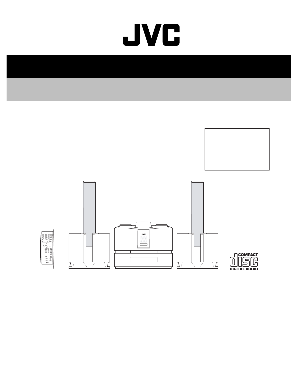
SERVICE MANUAL
COMPACT CONPONENT SYSTEM
FS-X5
Area suffix
US ---------------------- Singapore
UP ---------------------------- Korea
UT --------------------------- Taiwan
UW ---------- Brazil,Mexico,Peru
UJ --------------------- U.S.Military
SP-FSX5 SP-FSX5CA-FSX5
TABLE OF CONTENTS
1 PRECAUTION. . . . . . . . . . . . . . . . . . . . . . . . . . . . . . . . . . . . . . . . . . . . . . . . . . . . . . . . . . . . . . . . . . . . . . . . . 1-3
2 SPECIFIC SERVICE INSTRUCTIONS. . . . . . . . . . . . . . . . . . . . . . . . . . . . . . . . . . . . . . . . . . . . . . . . . . . . . . 1-6
3 DISASSEMBLY . . . . . . . . . . . . . . . . . . . . . . . . . . . . . . . . . . . . . . . . . . . . . . . . . . . . . . . . . . . . . . . . . . . . . . . 1-7
4 ADJUSTMENT . . . . . . . . . . . . . . . . . . . . . . . . . . . . . . . . . . . . . . . . . . . . . . . . . . . . . . . . . . . . . . . . . . . . . . . 1-20
5 TROUBLESHOOTING . . . . . . . . . . . . . . . . . . . . . . . . . . . . . . . . . . . . . . . . . . . . . . . . . . . . . . . . . . . . . . . . . 1-23
COPYRIGHT © 2003 VICTOR COMPANY OF JAPAN, LIMITED
No.MB051
2003/10
Page 2
SPECIFICATION
Amplifier Output Power Main : 60 W (30 W + 30 W) at 4 Ω (1 kHz 10% THD)
Sub : 60 W (30 W + 30 W) at 4 Ω (80 Hz 10% THD)
Imput Sensitivity/Impedance (1 kHz) LINE IN 210 mV/51 kΩ (LEVEL 1)
520 mV/51 kΩ (LEVEL 2)
Output Sensitivity/Impedance (1 kHz) LINE OUT 600 mV/5.1 kΩ
OPTICAL DIGITAL OUT -23 dBm to -15 dBm
Speaker terminals MIN. 4 Ω
Phones 16 Ω to 1 kΩ
CD Player Signal-To-Noise Ratio 95 dB
Wow And Flutter Unmeasurable
Tuner FM Tuner Tuning Range 87.5 MHz - 108.0 MHz
AM Tuner Tuning Range 530 kHz - 1 710 kHz
Power Specifications Power Requirements AC 110 V ~, 230 Hz
Power Consumption For 110 V 27 W (power on mode)
1.2 W (on Standby: with display off)
4.5 W (on Standby: with display on)
For 230 V 30 W (power on mode)
2.0 W (on Standby: with display off)
7.0 W (on Standby: with display on)
Center Unit Dimensions 160 mm × 130 mm × 242 mm (W/H/D)
Mass Approx. 2.3 kg
Speaker Specification Type 2-Way Bass-reflex type
Main-Speaker 9.5 cm × 1 cm Direct drive
Power Handling Capcity : 30W
Impedance : 4 Ω
Sub-woofer 9.0 cm cone
Power Handling Capcity : 30 W
Impedance :4 Ω
Sound Pressure Level 77 dB/W
Cross over frequency 210 Hz
Frequency Range 52 Hz to 20 000 Hz
Dimensions 140 mm × 301.5 mm × 185 mm (W/H/D)
Mass Approx. 2.3 kg each
Accessories FM Wire Antenna (1), AM Loop Antenna (1), Remote Control (1), Batteries (2), Speaker Cords (4),
AC plug adapter (1)
·m
1-2 (No.MB051)
Page 3
1.1 Safety Precautions
Good earth ground
d
AC VOLTMETER
SECTION 1
PRECAUTION
(1) This design of th is product contains special hardw are and
many circuits and components specially for safety purposes. For continued protection, no changes should be made
to the original design unless authorized in writing by the
manufacturer. Replacement parts must be identical to
those used in the original circuits. Services should be performed by qualified personnel only.
(2) Alterations of the design or circuitry of the product should
not be made. Any design alterations of the product should
not be made. Any design alterations or additions will void
the manufacturers warranty and will further relieve the
manufacture of responsibility for personal injury or property
damage resulting therefrom.
(3) Many electrical and mechanical parts in the products have
special safety-related characteristics. These characteristics are often not evident from visual inspection nor can the
protection afforded by them necessarily be obtained by using replacement components rated for higher voltage, wattage, etc. Replacement parts which have these special
safety characteristics are identified in the Parts List of Service Manual. Electrical components having such features
are identified by shading on the schematics and by ( ) on
the Parts List in the Service Manual. The use of a substitute
replacement which does not have the same safety characteristics as the recommended replacement parts shown in
the Parts List of Service Manual may create shock, fire, or
other hazards.
(4) The leads in the products are routed and dressed with ties,
clamps, tubings, barriers and the like to be separated from
live parts, high temperature parts, moving parts and/or
sharp edges for the prevention of electric shock and fire
hazard. When service is required, the original lead routing
and dress should be observed, and it should be confirmed
that they have been returned to normal, after reassembling.
(5) Leakage shock hazard testing
After reassembling the product, always perform an isolation check on the exposed metal parts of the product (antenna terminals, knobs, metal cabinet, screw heads,
headphone jack, control shafts, etc.) to be sure the product
is safe to operate without danger of electrical shock.Do not
use a line isolation transformer during this check.
• Plug the AC line cord directly into the AC outlet. Using a
"Leakage Current Tester", measure the leakage current
from each exposed metal parts of the cabinet, particularly any exposed metal part having a return path to the
chassis, to a known good earth ground. Any leakage current must not exceed 0.5mA AC (r.m.s.).
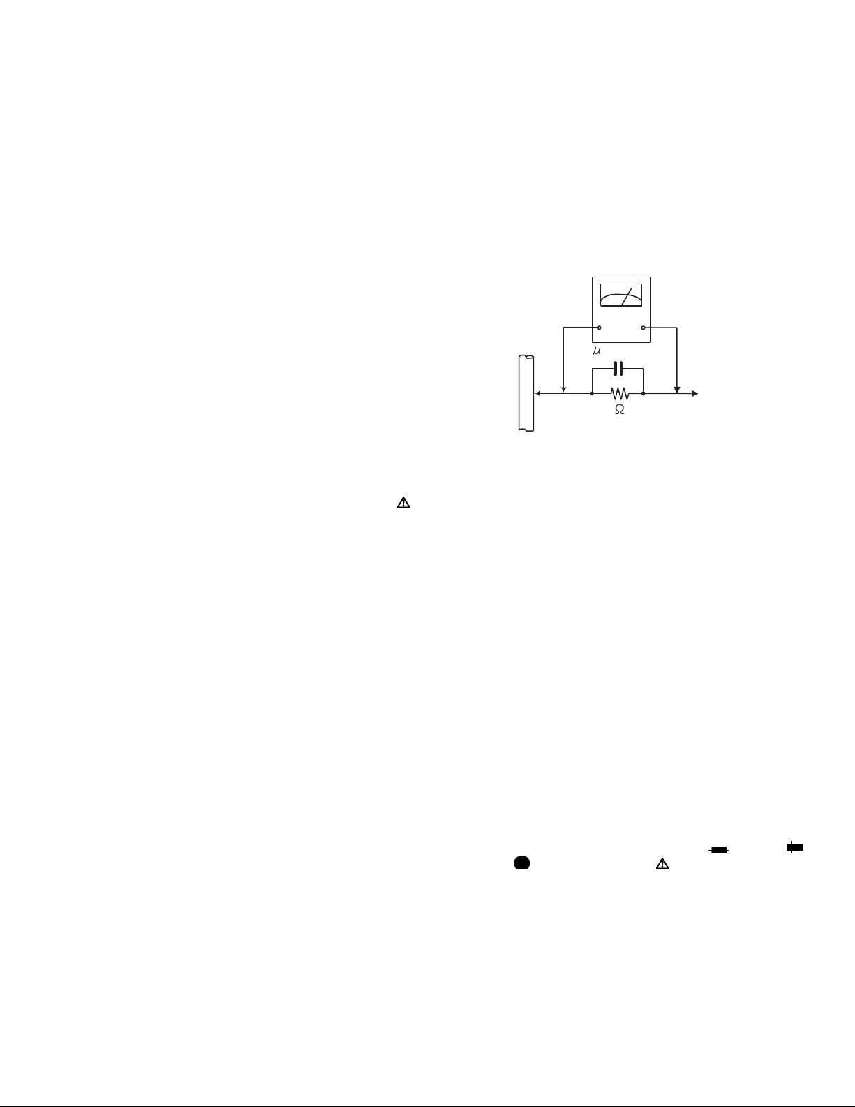
• Alternate check method
Plug the AC line cord directly into the AC outlet. Use an
AC voltmeter having, 1,000Ω per volt or more sensitivity
in the following manner. Connect a 1,500Ω 10W resistor
paralleled by a 0.15µF AC-type capacitor between an exposed metal part and a known good earth ground.
Measure the AC voltage across the resistor with the AC
voltmeter.
Move the resistor connection to each exposed metal
part, particularly any exposed metal part having a return
path to the chassis, and measure the AC voltage across
the resistor. Now, reverse the plug in the AC outlet and
repeat each measurement. Voltage measured any must
not exceed 0.75 V AC (r.m.s.). This corresponds to 0.5
mA AC (r.m.s.).
(Having 1000
ohms/volts,
or more sensitivity)
0.15 F AC TYPE
Place this
probe on
1500 10W
1.2 Warning
(1) This equipment has been designed and manufactured to
meet international safety standards.
(2) It is the legal resp onsibility of the repairer to ensure that
these safety standards are maintained.
(3) Repairs must be made in accordance with the relevant
safety standards.
(4) It is essential that safety critical compone nts are replaced
by approved parts.
(5) If mains voltage selector is provided, check setting for local
voltage.
1.3 Caution Burrs formed during molding may be left over on some parts
of the chassis.
Therefore, pay attention to such burrs in the case of preforming repair of this system.
1.4 Critical parts for safety
In regard with component parts appearing on the silk-screen
printed side (parts side) of the PWB diagrams, the parts that are
printed over with black such as the resistor ( ), diode ( )
and ICP ( ) or identified by the " " mark nearby are critical
for safety. When replacing them, be sure to use the parts of the
same type and rating as specified by the manufacturer.
(This regulation dose not Except the J and C version)
each expose
metal part.
(No.MB051)1-3
Page 4
1.5 Preventing static electricity
Electrostatic discharge (ESD), which occurs when static electricity stored in the body, fabric, etc. is discharged, can destroy the laser
diode in the traverse unit (optical pickup). Take care to prevent this when performing repairs.
1.5.1 Grounding to prevent damage by static electricity
Static electricity in the work area can destroy the optical pickup (laser dio de) in devices such as CD players.
Be careful to use proper grounding in the area where repairs are being performed.
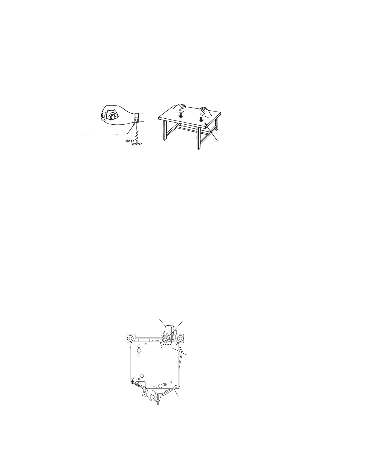
(1) Ground the workbench
Ground the workbench by laying conductive material (such as a conductive sh eet) or an iron plate over it before placing the
traverse unit (optical pickup) on it.
(2) Ground yourself
Use an anti-static wrist strap to release any static electricity built up in your body.
(caption)
Anti-static wrist strap
Conductive material
(conductive sheet) or iron plate
(3) Handling the optical pickup
• In order to maintain qua lity during transport and befo re installation, both sides o f the laser diode on the replacem ent optical
pickup are shorted. After replacement, return the shorted parts to their original condition.
(Refer to the text.)
• Do not use a tester to check the condition of the laser diode in the optical pickup. The tester's internal power source can easily
destroy the laser diode.
1.6 Handling the traverse unit (optical pickup)
(1) Do not subject the traverse unit (optical pickup) to strong shocks, as it is a sensitive, complex unit.
(2) Cut off the shorted part of the flexible cable using nippers, etc. after replacing the optical pickup. For specific details, refer to the
replacement procedure in the text. Remove the anti-static pin when replacing the traverse unit. Be careful not to take too long
a time when attaching it to the connector.
(3) Handle the flexible cable carefully as it may break when subjected to strong force.
(4) I t is not possible to adjust the semi-fixed resistor that adjusts the laser power. Do not turn it.
1.7 Attention when traverse unit is decomposed *Please refer to "Disassembly method" in the text for the CD pickup unit.
• Apply solder to the short land sections before the fl exible wire is disconnected from the connector CN601
on the CD servo board.
(If the flexible wire is disconnected without applying solder, the CD pickup may be destroyed by static electricity.)
• In the assembly, be sure to remove solder from the short land sections after connecting the flexible wire.
Flexible wire
Short land section
CN601
1-4 (No.MB051)
CD servo board
Page 5
1.8 Important for laser products
1.CLASS 1 LASER PRODUCT
2.DANGER : Invisible laser radiation when open and inter
lock failed or defeated. Avoid direct exposure to beam.
3.CAUTION : There are no serviceable parts inside the
Laser Unit. Do not disassemble the Laser Unit. Replace
the complete Laser Unit if it malfunctions.
4.CAUTION : The compact disc player uses invisible
laserradiation and is equipped with safety switches
whichprevent emission of radiation when the drawer is
open and the safety interlocks have failed or are de
feated. It is dangerous to defeat the safety switches.
VARNING : Osynlig laserstrålning är denna del är öppnad
och spårren är urkopplad. Betrakta ej strålen.
VARO : Avattaessa ja suojalukitus ohitettaessa olet
alttiina näkymättömälle lasersäteilylle.Älä katso
säteeseen.
5.CAUTION : If safety switches malfunction, the laser is able
to function.
6.CAUTION : Use of controls, adjustments or performance of
procedures other than those specified herein may result in
hazardous radiation exposure.
!
Please use enough caution not to
see the beam directly or touch it
in case of an adjustment or operation
check.
ADVARSEL : Usynlig laserstråling ved åbning , når
sikkerhedsafbrydere er ude af funktion. Undgå
udsættelse for stråling.
ADVARSEL : Usynlig laserstråling ved åpning,når
sikkerhetsbryteren er avslott. unngå utsettelse
for stråling.
CLASS 1
LASER PRODUCT
CLASS 1 LASER PRODUCT LABEL (UP only)
LASER CAUTION LABEL
LV42035-
(No.MB051)1-5
Page 6

SECTION 2
SPECIFIC SERVICE INSTRUCTIONS
This service manual does not describe SPECIFIC SERVICE INSTRUCTIONS.
1-6 (No.MB051)
Page 7
SECTION 3
r
DISASSEMBLY
3.1 Main body section
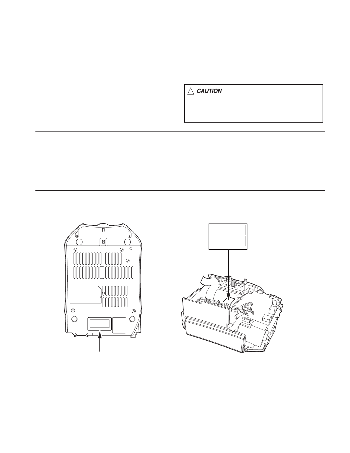
3.1.1 Removing the rear cover
(See Figs.1 and 2)
(1) From the back side of the main body, remove the fourteen
screws A attaching the rear cover. (See Fig.1.)
(2) Remove the two screws B attaching the fan cover. (See
Fig.1.)
(3) Remove the rear cover and disconnect the power cord
from the connector CN900
the main body. (See Fig.2.)
(4) Remove the strain relief in the direction of the arrow. (See
Fig.2.)
Reference:
Before attaching the rear cover, pass the power cord through
the guide hole a on the rear cover. (See Fig.2.)
on the power supply board of
A
A A
B
A
Fan cover
Power supply board
CN900
Power cord
B
Fig.1
Fig.2
Rear cover
A
Strain relief
Gurde hole a
Rear cove
(No.MB051)1-7
Page 8
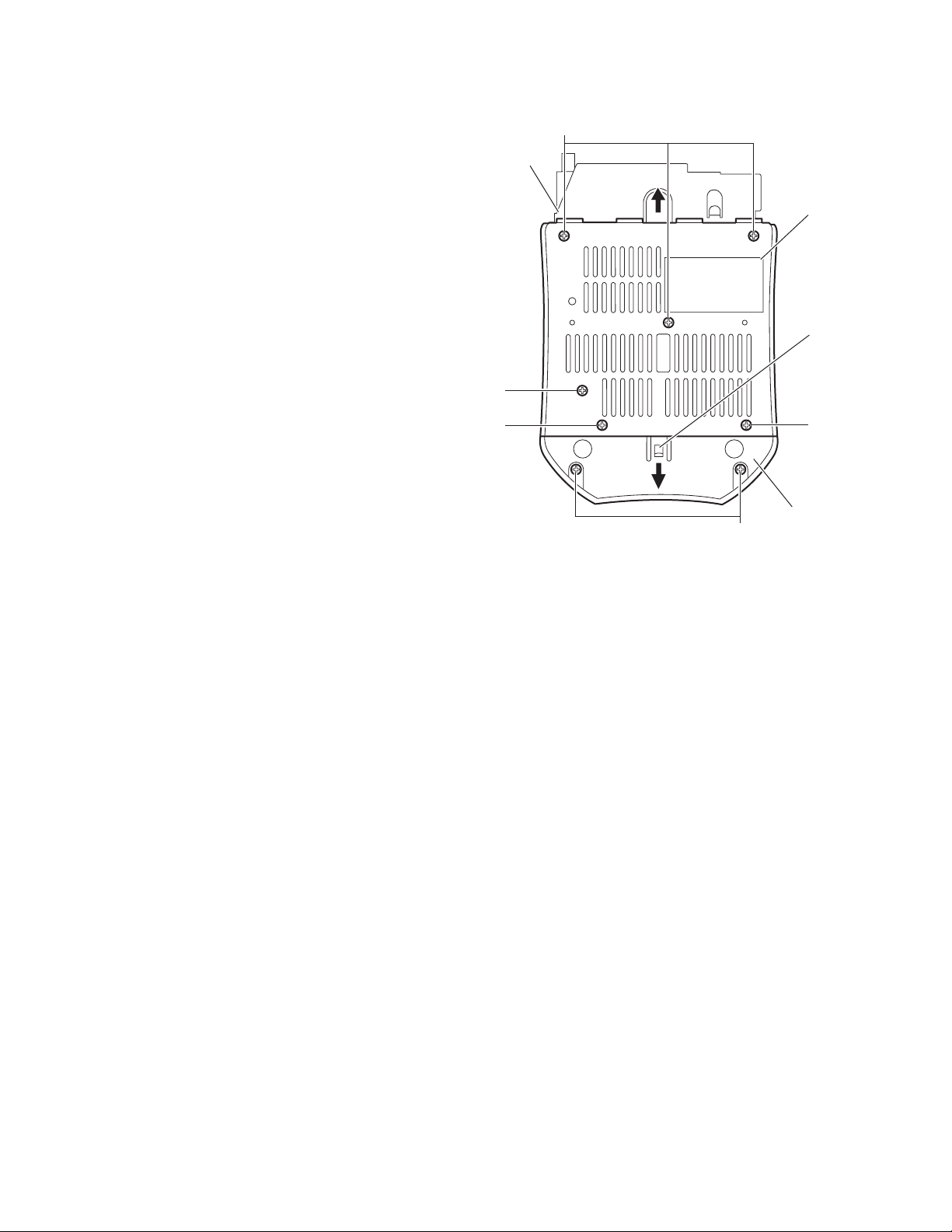
3.1.2 Removing the bottom case (A)
(See Fig.3)
• Prior to performing the following procedures, remove the rear
cover.
(1) From the bottom side of the main body, remove five screws
C and screw D attaching the bottom case (A).
(2) Remove the bottom case (A) in the direction of the arrow
while lifting the rear section of the bottom case (A)
3.1.3 Removing the bottom case (B)
(See Fig.3)
(1) From the bottom side of the main bo dy, remove the two
screws E attaching the bottom case (B).
(2) Release the claw b of the bottom case (B) and remove the
bottom case in the direction of the arrow.
Note:
When turning the main body upside down to remove the
bottom case (A) and the bottom case (B), place a cushion
beneath the main body so as not to scratch the top case
assembly, volume control knob or other parts.
Bottom
chassis
D
C
C
Fig.3
E
Bottom
case (A)
Claw b
C
Bottom
case(B)
1-8 (No.MB051)
Page 9

3.1.4 Removing the top case assembly
(See Figs.4 to 7)
• Prior to performing the following proce dures, remove the rear
cover and bottom case (B).
(1) From the front side of the main body, remove the two
screws F attaching the top case assembly. (See Fig.4.)
(2) Disconnect the card wires from the connectors CN721
CN741 on the micon board. (See Fig.4.)
(3) From the back side of the main body, disconnect the wire
from the connector CN451
Fig.5.)
(4) Remove the top case assembly whi le lifting it in the direc-
tion of the arrow. (See Fig.5.)
(5) From the inside of the top case assembly, disconnect the
card wire from the connector CN651
board. (See Figs.6 and 7.)
Reference:
Reassembly of the top case assembly
• Before reattaching the top case assembly to the main body,
connect the card wire to the connector CN651
servo board and hang it to the holder sections c of the CD
mechanism assembly. (See Figs. 6 and 7.)
• Let the card wire to be connected across the connectors
and CN741 go through the slit d on the top case
CN721
assembly. (See Fig. 7.)
on the function board. (See
on the CD servo
and
on the CD
Top case assembly
CN741
Card wires
CN721
Micon board
F
Fig.4
Top case assembly
Wire
CN451
Function board
CD mechanism
assembly
CD servo board
CD servo board
Holder
sections c
Fig.5
Top case
assembly
CN651
Holder
sections c
Fig.6
Top case assembly
CN651
Slit d
Card wire
CD mechanism assembly
Fig.7
(No.MB051)1-9
Page 10

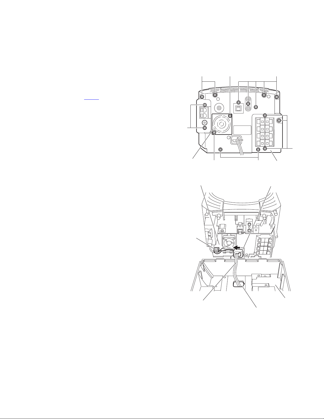
3.1.5 Removing the tuner unit
r
(See Fig.8)
• Prior to performing the following procedures, remove the rear
cover, bottom case (B) and top case assembly.
(1) From the right side of the main body, disconnect the card
wire from the connector CN1
on the tuner unit.
CN1
3.1.6 Removing the function board
(See Fig.9)
• Prior to performing the following procedures, remove the rear
cover, bottom case (B) and top case assembly.
(1) From the top side of the main body, disconnect the fan
motor wire from the connector CN942
board.
(2) Disconnect the wires from the connectors CN893
on the function board.
CN895
(3) Remove the spacer and tie band fixing the wire.
(4) Disconnect the wire from the connector CN301 on the
digital amplifier board.
(5) Remove the three screws G attaching the function board.
(6) Lift the function board in the direction of the arrow and
disconnect it from the connector CN951
amplifier board.
Reference:
When connecting the fan motor wire, put it through the slit e of
the function board.
3.1.7 Removing the micon board
(See Fig.10)
• Prior to performing the following procedures, remove the rear
cover, bottom case (A), bottom case (B) and top case
assembly.
(1) From the right side of the main body, remove the tie bands
bundling the wires.
(2) Disconnect the wire from the connector CN805
micon board.
(3) Disconnect the card wires from the connectors CN661
on the micon board.
CN871
(4) Disconnect the wire from the connector CN893
function board.
(5) Remove the two screws H and two screws J atta ch ing the
micon board.
(6) Pull the micon board toward this side, disconnect the
connectors CN801
Reference:
• After connecting the card wire to the connector CN661
the micon board, bend it as was done before disassembly
and insert it inside the center chassis.
• After connecting the wires to the connectors
(CN805
the wires with the tie bands.
,CN893) on the micon and function boards, bundle
and CN802 on the micon board.
on the function
and
on the digital
on the
and
on the
on
Tie band
CN301
Wire
Micon board
H
J
Card wire
Digital amplifier
board
Spacer
CN805
CN801
CN661
Card wire
Fig.8
CN942
G
Fig.9
Wire
CN802
Fig.10
CN951
G
Wire
CN893
Tie bands
J
Function board
Fan motor wire
CN871
Tune
CN895
G
Slit e
Fan motor
Fanction board
CN893
H
Card wire
1-10 (No.MB051)
Page 11

3.1.8 Removing the digital amplifier board
(See Fig.11)
• Prior to performing the following proce dures, remove the rear
cover, bottom case (A), bottom case (B) and top case
assembly.
(1) From the left side of the main body, disconnect the wire
from the connector CN301
(2) Remove the spacer and tie band fixing the wire.
(3) Remove the two screws K, two screws L and screw L’
attaching the digital amplifier board.
(4) Pull the digital amplifier board toward this side, disconnect
the connectors CN961
board.
Reference:
• When attaching the screw L’, atta ch the earth wire together
it.
• After connecting the wire, fix the wire with the spacer and tie
band.
3.1.9 Removing the power supply board
(See Figs.12 to 14)
• Prior to performing the following proce dures, remove the rear
cover, bottom case (A), bottom case (B), top case assembly,
function board, micon board and digital amplifier board.
(1) From the top side of the main body, remove the two screws
M attaching the center chassis. (See Fig.12.)
(2) From the bottom side of the main body, remove the two
screws N attaching the power supply board. (See Fig.13.)
(3) Disconnect the card wire from the connector CN903
power supply board. (See Fig.14.)
(4) Remove the three screws P attaching the power supply
board. (See Fig.14.)
Reference:
• Remove the barrier (E) and barrier (F) under the power
supply board as required. (See Fig.14.)
• Before attaching the each parts, pass the card wire through
the holes f on the center chassis. (See Fig.12.)
Card wire
on the digital amplifier board.
and CN981 on the digital amplifier
on the
Hole f
Center chassis
M
Digital amplifier board
CN981
CN961
Earth Wire
L
N
N
K
Spacer
CN301
L'
Fig.11
Power supply board
Bottom chassis
Fig.13
Power supply board
P
Tie band
K
Wire
L
Card wire
Bottom chassis
Fig.12
M
P
Barrier (E)
Barrier (F)
P
CN903
Fig.14
(No.MB051)1-11
Page 12

3.1.10 Removing the regulator board
(See Fig.15)
• Prior to performing the following procedures, remove the rear
cover, bottom case (A), bottom case (B), top case assembly,
tuner unit, function board, micon board, digital amplifier board
and power supply board.
(1) From the side of the power supply board , remove the two
screws Q attaching the regulator board.
(2) Disconnect the regulator board from the connector CN931
on the power supply board in the direction of the arrow.
Q
Regulator board
Q
3.1.11 Removing the FL board
(See Fig.16)
• Prior to performing the following procedures, remove the rear
cover, bottom case (B) and top case assembly.
(1) From the top side of the main bod y, disconnect the card
wire from the connector CN751
(2) Remove the screw R attaching the FL board.
(3) Release the two engagement sections g of the bottom
chassis, take out the FL board.
on the FL board.
Power supply board
FL board
Engagement
section g
CN751
R
Card wire
Engagement
section g
CN931
Fig.15
Fig.16
1-12 (No.MB051)
Page 13

3.2 Top case assembly section
• Prior to performing the follow ing procedures, remove the top
case assembly.
Note:
Be careful not to scratch the top case, volume control knob or
other parts.
3.2.1 Removing the CD mechanism assembly
(See Fig.17)
(1) From the inside of the top case assembly, remove the three
screws S attaching the CD mechanism assembly.
(2) Take out the CD mecha nism assembly from the top case
assembly.
3.2.2 Removing the CD door mechanism assembly
(See Figs.17 and 18)
(1) Remove the cover in the direction of the arrow. (See
Fig.17.)
(2) From the inside of the top case assembly, disconnect the
wire from the connector CN461
board. (See Fig.17.)
(3) Remove the three screws T attaching the gear bracket and
take out the gear bracket. (See Fig.17.)
(4) Remove the two screws U attaching the CD door
mechanism assembly and take out the CD door
mechanism assembly. (See Fig.17.)
Reference:
Before attaching the CD door mechanism assembly, put the
wire through the two slits h of the CD door mechanism
assembly and then attach the two screws U. (See Figs.17 and
18.)
on the CD door switch
Top case assembly
CD mechanism assembly
S
T
Gear bracket
U
Fig.17
CD door
mechanism assembly
CD door
mechanism
assembly
T
Cover
CD door
switch
board
CN461
Fig.18
Slits h
(No.MB051)1-13
Page 14

3.2.3 Removing the CD door switch board
r
(See Fig.19)
• Prior to performing the following procedures, remove the C D
door mechanism assembly.
(1) Disconnect the wire of the CD door motor from the
connector CN452
(2) Remove the screw V attaching the CD door switch board.
(3) Release the CD door switch board from the projection i and
then remove it from the engagement section j in the direc-
tion of the arrow.
3.2.4 Removing the CD door motor
(See Figs.19 and 20)
• Prior to performing the following procedures, remove the C D
door mechanism assembly.
(1) Disconnect the wire of the CD door motor from the
connector CN452
Fig.19.)
(2) Turn over the CD door mechanism assembly and remove
the belt. (See Fig.20.)
(3) Remove the two screws W attaching the CD d oor motor.
(See Fig.20.)
Note:
Take care not to attach grease of the gears on the belt.
on the CD door switch board.
on the CD door switch board. (See
CD door motor
Engagement section j
CD door mechanism assembly
CN452
Fig.19
CD door
mechanism assembly
CD door
switch board
Projection i
V
Belt
3.2.5 Removing the CD door assembly
(See Fig.21)
• Prior to performing the following procedures, remove the C D
mechanism assembly and CD door mechanism assembly.
(1) From the inside of the top case assembly, remove the boss
m of the CD door assembly while extending the section k
of the top case assembly in the direction of the arrow.
(2) Remove the boss p of the CD door assembly while
extending the section n of the top case assembly in the
direction of the arrow.
Section n
Boss p
Fig.20
Top case assembly
CD door assembly
Fig.21
CD doo
motor
W
Section k
Boss m
1-14 (No.MB051)
Page 15

3.2.6 Removing the CD door LED board
(See Fig.22)
• Prior to performing the followi ng procedures, remove the CD
mechanism assembly, CD door mechanism assembly and CD
door assembly.
(1) From the reverse side of the CD door assembly, remove
the five screws X attaching the CD door cover.
(2) Remove the screw X attaching the CD door LED board.
(3) After removing the CD door cover, remove the CD door
LED board from the projections (q, r) and take out it in the
direction of the arrow.
CD door cover
X
CD door
Projection q
X
CD door
LED board
3.2.7 Removing the front holder assembly
(See Fig.23)
• Prior to performing the followi ng procedures, remove the CD
mechanism assembly.
(1) From the inside of the top case assembly, remove the two
screws Y attaching the front holder assembly.
(2) Take out the front holder assembly.
3.2.8 Removing the front board
(See Fig.24)
• Prior to performing the followi ng procedures, remove the CD
mechanism assembly and front holder assembly.
(1) From the forward side of the front holder assembly, remove
the three screws Z attaching the front board.
Reference:
• Remove the card wire from the connector CN731
front board as required.
• Before attaching the front board, pass the card wire through
the hole s on the front holder assembly.
on the
X
Front holder assembly
Y
Front holder assembly
Z
Projection r
Fig.22
Top case assembly
Fig.23
Z
Front board
Card wire
Hole s
CN731
Z
Fig.24
(No.MB051)1-15
Page 16

3.2.9 Removing the volume board and LED board
(See Figs.25 to 29)
• Prior to performing the following procedures, remove the C D
mechanism assembly and front holder assembly.
(1) From the top side of the top case assembly, pull out the
volume and function knobs. (See Fig.25.)
(2) From the inside of the top case assembly, remove the three
screws AA and screw AA’ attaching the volume board.
(See Fig.26.)
Reference:
When attaching the screw AA’, attach the barrier (D)
together it.
(3) Remove the screw AA attaching the LED board. (See
Fig.26.)
(4) Take out the volume board together the LED boa rd.
(5) From the reverse side of the volume bo ard, release the
three claws t attaching the push button (A). (See Fi g.27.)
(6) Remove the solders from the soldered section u on the
volume board and disconnect the parallel wire. (See
Fig.27.)
(7) Release the claw v of the push button (A) and remove the
LED board from the engagement sections w of the push
button (A) in the direction of the arrow. (See Fig.28.)
(8) Release the claws x of the button base (B) and remove the
button base (B) from the volume board. (See Fig.29.)
Function knob
Volume knob
Soldered
section u
Claw t
Claw v
Parallel wire
Volume board
LED board
Push button (A)
Fig.27
Engagement
sections w
Volume board
AA'
AA
Fig.25
Barrier (D)
Top case assembly
Top case assembly
LED board
LED board
Push button (A)
Fig.28
Volume board
Claws x
Button base(B)
Fig.29
AA
1-16 (No.MB051)
AA
Fig.26
Page 17

3.3 CD mechanism assembly section
• Prior to performing the followi ng procedures, remove the CD
mechanism assembly.
3.3.1 Removing the CD traverse mechanism assembly
(See Figs.1 and 2)
(1) From the forward side of th e CD traverse mechanism as-
sembly, release the two joints a attaching the pickup cover
to the CD traverse mechanism assembly. (See Fig.1.)
(2) Remove the three screws A attaching the CD traverse
mechanism assembly to the CD mechanism holder and
take out the CD traverse mechanism assembly. (See
Fig.1.)
Reference :
After attaching the assist spring to the CD mechanism holder,
attach the CD traverse mechanism assembly to the CD mechanism holder. (See Fig.2.)
A
CD traverse
mechanism
assembly
Joints a
3.3.2 Removing the CD servo board
(See Fig.3)
• Prior to performing the followi ng procedures, remove the CD
traverse mechanism assembly.
Caution :
Be sure to solder the short land section b on the flexible wire
before disconnecting the flexible wire from connector CN601
on the CD servo board.
If the flexible wire is disconnected without attaching solder, the
pickup may be destroyed by static electricity.
(1) From the reverse side of the CD traverse mechanism as-
sembly, solder the short land section b on the flexible wire.
(2) Disconnect the flexible wire from the connector CN601
the CD servo board.
(3) Remove the three screws B attaching the CD servo board.
(4) Remove the solders from the two soldered section c and d,
remove the CD servo board in an upward direction.
Caution :
When attaching the CD servo board, be sure to remove the
solder from the short land section b after connecting the flexible wire.
on
CD pickup cover
A
Fig.1
CD traverse mechanism assembly
CD mechanism holder
Fig.2
Flexible wire
B
soldered
section c
B B
soldered section d
CD traverse mechanism assembly
Fig.3
CD mechanism holder
Assist spring
Short land section b
CN601
CD servo board
(No.MB051)1-17
Page 18

3.3.3 Removing the pickup assembly
(See Figs.4 to 7)
• Prior to performing the following procedures, remove the C D
traverse mechanism assembly.
Caution :
Be sure to solder the short land section b on the flexib le wire
before disconnecting the flexible wire fro m connector CN601
on the CD servo board.
If the flexible wire is disconnected without attaching solder, the
pickup may be destroyed by static electricity.
(1) From the reverse side of the CD traverse mechanism as-
sembly, solder the short land section b on the flexible wire.
(See fig.4.)
(2) Disconnect the flexible wire from the connector CN601
the CD servo board. (See fig.4.)
(3) From the top side of th e CD traverse mechanism assem-
bly, turn the middle gear in the direction of the arrow so that
the pickup assembly is shifted to the reverse side of the
turn table assembly.
Move the pickup assembly until the section e of the rack
plate in the lower section of the pickup assembly comes out
of the chassis base assembly. (See fig.5.)
(4) Remove the two screws C attaching the shaft of the pickup
assembly. Next, disengage the hook f from the chassis
base assembly and then remove the pickup assembly with
the shaft. (See fig.6.)
(5) Pull the shaft out of the pickup assembly. (See fig.7.)
(6) Remove the two screws D attaching the rack plate to the
pickup. (See fig.7.)
(7) Remove the screw E attaching the P.S.spring to the pick-
up. (See fig.7.)
on
Rack plate
Section e
Middle gear
C
Flexible wire
CD servo board
Chassis base assembly
Pickup assembly
Short land section b
CN601
Fig.4
Turn table assembly
Pickup assembly
Fig.5
Section f
Shaft
Rack plate
Chassis assembly
C
Fig.6
Pickup
P.S.spring
E
D
Fig.7
1-18 (No.MB051)
Page 19

3.3.4 Reinstalling the pickup assembly
(See Figs.8 and 9)
Reference :
Refer to the explanation of "Removing the pickup assembly"
on the preceding page.
(1) Attach the P.S.spring and rack plate to the pickup.
(2) Insert the shaft into the pickup.
(3) Engage the hook f of the pi ckup assembly to the chassis
base assembly first, and set the section e of the rack plate
in the opening section g.
Then reinstall the pickup assembly while shifting it to the
turn table assembly side (inward) so that the section h of
the rack plate is positioned as shown in Fig.9.
(4) Move the pickup assembly to the center position and fasten
the shaft with the two screws C. (Make sure that the section
i of the rack plate is correctly engaged with the rack gear.)
(5) After passing the flexible wire of the pickup through the
opening section of the chassis base assembly, connect it
to the connector CN601
Note :
When reinstalling the pickup assembly, remove the solder
from the short land section b after connecting the flexible wire
to the connector CN601
on the CD servo assembly.
on the CD servo board.
Section f
Section e
Pickup
assembly
Section g
Chassis base
assembly
Fig.8
3.3.5 R emoving the feed motor assembly
(See Fig.10)
• Prior to performing the followi ng procedures, remove the CD
traverse mechanism assembly and CD servo board.
From the forward side of the CD traverse mechanism asse mbly, remove the two screws F attaching the feed motor assembly.
Section h
Rack gear
Section i
Rack plate
Fig.9
F
Feed motor assembly
Fig.10
(No.MB051)1-19
Page 20

4.1 Test instruments required for adjustment
(1) Digital oscilloscope
(2) Electric voltmeter
(3) Test disk : CTS-1000
4.2 Adjusting and confirming contents
4.2.1 Adjustment of the CD section
(1) Indication of the C1 error (CD test mode 1)
(2) Indication of the auto adjusting value (CD test mode 2)
(3) Cancellation of the test mode
4.2.2 System test mode (FL all lighting-up check)
4.3 Adjusting and confirming methods
4.3.1 Adjusting and confirming of the CD section
(1) Indication of the C1 error (CD test mode 1)
While pressing both the STOP and
AHB plus buttons on the main
unit, turn on the primary power supply.
SECTION 4
ADJUSTMENT
Press the STANDBY/ON button
on the main unit.
FL indication
CD TEST MODE 1
Press the OPEN/CLOSE button
on the main unit and insert the
test disc.
Press key 1, 2 or 4 of the remote control
unit to start measurement. The number of
error corrections will be displayed every 10
seconds.
Key 1: Normal-speed playback
Key 2: 2x-speed playback
Key 4: 4x-speed playback
FL indication
x1 Err
x2 Err
1-20 (No.MB051)
x4 Err
Page 21

(2) Indication of the auto adjusting value (CD test mode 2)
While pressing both the STOP and
AHB plus buttons on the main
unit, turn on the primary power supply.
Press the STANDBY/ON button
on the main unit.
FL indication
CD TEST MODE 1
Wait a moment while keeping to
press the SET key on the remote
controller.
FL indication
CD TEST MODE 2
Press the SET key on
the remote controller.
FL indication
:
Description of the indication
:
Adjusting value
Each time the SET key
on the remote controller
is pressed, the indication
changes from FG to AOC1.
FG
Mantissa part of the focus gain
FEXP
Characteristic part of the focus gain
E2 status
E3 status
E1 status
FBAL
Adjusting value of the focus balance
FOFS
Adjusting value of the focus offset
FES
Disturbance amplitude during the focus gain adjustment
TG
Mantissa part of the tracking gain
TEXP
Characteristic part of the tracking gain
TBAL
Tracking balance adjusting value
TOFS
Tracking offset adjusting value
TES
Disturbance amplitude during the tracking gain adjustment
FAGC
Focus precise gain
ABC2
Tracking balance
ABC1
Focus balance
AGC2
Tracking coarse gain
AGC1
Focus coarse gain
AOC1
Focus offset
Press the CANCEL key
on the remote controller.
FL indication
CD TEST MODE 1
(3) Cancellation of the test mode
To cancel the test mode, press the STANDBY/ON button on the main unit.
(No.MB051)1-21
Page 22

4.3.2 System test mode (FL all lighting-up check)
Go to the Adjustment Mode.
Press the "2", "STOP" and "STANDBY/ON"
keys on the remote controller simultaneously.
FL indication
All lighting-up
By pressing any of the keys on the
remote controller, the initial display
screen is resumed.
By pulling out the power supply cord of the
main unit the test mode will be canceled.
In the adjustment mode a 1-second real-time
increment sets the clock to gain 1 minute.
1-22 (No.MB051)
Page 23

TROUBLESHOOTING
5.1 Flow of functional operation until TOC rea d
Power ON
Disc play Key
Automatic tuning of FO offset and TE offset
SECTION 5
Slider turns REST
SW ON.
Laser ON
Detection of disc
Check Point
Confirm that the voltage at
the pin32 of IC251 is 0V.
(ON: 0V)
Tracking error waveform at TOC reading
IC601
20pin(TEOUT)
Approx.
1.4V
VREF
Disc status
to rotate
Approx. 3sec
Tracking
servo
off status
Automatic measurement
of TE amplitude and
automatic tuning of TE
balance
Tracking
servo
on status
Disc to be
braked to stop
TOC reading
finishes
500mv/div
2ms/div
Fig.1
Automatic measurement of
Focus S-curve amplitude
Disc is rotated
Focus servo ON
(Tracking servo ON)
Automatic measurement of
Tracking error amplitude
Automatic tuning of
Tracking error balance
Automatic tuning of
Focus error balance
Automatic tuning of
Focus error gain
Confirm that the Focus error
S-curve signal at the pin32 of
IC651 is approx. 1.4Vp-p.
Confirm that the signal from
pin24 of IC651(one side of
R808) is 0V as a accelerated
pulse during approx. 640ms.
Confirm the waveform of the
Tracking error signal at the
pin20 of IC601(one side of
R604) (See Fig.1.)
Automatic tuning of
Tracking error gain
TOC reading
Play a disc
Confirm the eye-pattern
at the pin5 of IC601
(No.MB051)1-23
Page 24

5.2 Maintenance of laser pickup
(1) Cleaning the pickup lens
Before you replace the pickup, please try to clean the lens
with a alcohol soaked cotton swab.
(2) Life of the laser diode
When the life of the laser diode has expired, the following
symptoms will appear.
Is RF output
0.9 0.22Vp-p?
NO
Replace it.
5.3 Replacement of laser pickup
Turn of the power switch and, disconnect the
power cord.
Replace the pickup with a normal one. (Refer
to "Pickup Removal" on the previous page)
YES
O.K
(3) The level of RF output (EFM output, amplitude of eye pat-
tern: pin5 of IC601
(4) Semi-fixed resistor on the APC PC board
The semi-fixed resistor on the APC printed circuit board
which is attached to the pickup is used to adjust the laser
power. Since this adjustment should be performed to
match the characteristics of the whole optical block, do not
touch the semi-fixed resistor. If the laser power is low er
than the specified value, the laser diode is almost worn out,
and the laser pickup should be replaced. If the semi-fixed
resistor is adjusted while the pickup is functioning normally,
the laser pickup may be damaged due to excessive current.
) will be low.
Plug the power cord in, and turn the power on.
At this time, check that the laser emits for
about 3 seconds and the objective lens moves
up and down.
Note: Do not observe the laser beam directly.
Play a disc.
Check the eye-pattern at 5pin of IC601.
Finish.
1-24 (No.MB051)
Page 25

(No.MB051)1-25
Page 26

VICTOR COMPANY OF JAPAN, LIMITED
AV & MULTIMEDIA COMPANY AUDIO/VIDEO SYSTEMS CATEGORY 10-1,1chome,Ohwatari-machi,Maebashi-city,371-8543,Japan
(No.MB051)
Printed in Japan
WPC
 Loading...