

Page 1
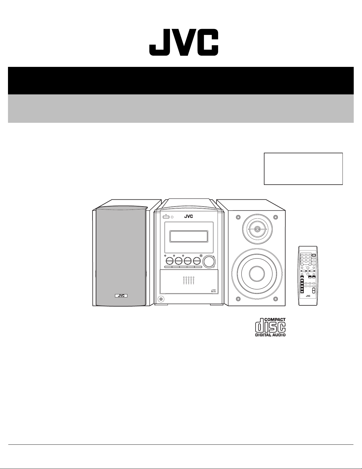
SERVICE MANUAL
COMPACT COMPONENT SYSTEM
MB20520044
FS-S57
Area suffix
J ----------------------------- U.S.A.
C -------------------------- Canada
TABLE OF CONTENTS
1 PRECAUTION. . . . . . . . . . . . . . . . . . . . . . . . . . . . . . . . . . . . . . . . . . . . . . . . . . . . . . . . . . . . . . . . . . . . . . . . . 1-3
2 SPECIFIC SERVICE INSTRUCTIONS . . . . . . . . . . . . . . . . . . . . . . . . . . . . . . . . . . . . . . . . . . . . . . . . . . . . . . 1-6
3 DISASSEMBLY . . . . . . . . . . . . . . . . . . . . . . . . . . . . . . . . . . . . . . . . . . . . . . . . . . . . . . . . . . . . . . . . . . . . . . . 1-7
4 ADJUSTMENT . . . . . . . . . . . . . . . . . . . . . . . . . . . . . . . . . . . . . . . . . . . . . . . . . . . . . . . . . . . . . . . . . . . . . . . 1-30
5 TROUBLESHOOTING . . . . . . . . . . . . . . . . . . . . . . . . . . . . . . . . . . . . . . . . . . . . . . . . . . . . . . . . . . . . . . . . . 1-31
COPYRIGHT © 2004 VICTOR COMPANY OF JAPAN, LIMITED
No.MB205
2004/4
Page 2
SPECIFICATION
Amplifier Section
CA-FSS57
Tuner FM tuning range 87.5 MHz-108.0 MHz
CD player CD Capacity 5 CDs
General Power requirement AC 120 V , 60 Hz
Speaker Section
SP-UXS57
Output Power 74 W per channel, min. RMS, driven into 6 Ω at 1 kHz with no more
than 10% total harmonic distortion.
Analog input sensitivity/Impedance (at 1 kHz) AUX/DVD:400 mV/48 kΩ
Speakers/Impedance 6 Ω - 16 Ω
AM tuning range 530 kHz-1 710 kHz
Dynamic range 87 dB
Signal-to-noise ratio 90 dB
Wow and flutter Immeasurable
Power consumption 110 W (at operation)
17 W (on standby)
1.4 W (in power save mode)
Dimensions (W/H/D) (approx.) 175 mm × 239.5 mm × 378 mm (6 15/16 in. × 9 1/2 in. × 14 15/16 in.)
Mass (approx.) 7.4 kg (16.3 lbs)
Type 2-way bass-reflex type
Speakers Woofer 12 cm cone × 1
Tweeter 4 cm cone × 1
Power handling capacity 60 W
Impedance 6 Ω
Frequency range 53 Hz to 30 kHz
Sound pressure level 84 dB/W·m
Dimensions (W/H/D) (approx.) 145 mm × 239.5 mm × 202 mm (5 3/4 in. × 9 1/2 in. × 8 in.)
Mass (approx.) 2.2 kg (4.9 lbs) each
Design and specifications are subject to change without notice.
1-2 (No.MB205)
Page 3
SECTION 1
PRECAUTION
1.1 Safety Precautions
(1) This design of this product contains special hardware and
many circuits and components specially for safety purposes. For continued protection, no changes should be made
to the original design unless authorized in writing by the
manufacturer. Replacement parts must be identical to
those used in the original circuits. Services should be performed by qualified personnel only.
(2) Alterations of the design or circuitry of the product should
not be made. Any design alterations of the product should
not be made. Any design alterations or additions will void
the manufacturers warranty and will further relieve the
manufacture of responsibility for personal injury or property
damage resulting therefrom.
(3) Many electrical and mechanical parts in the products have
special safety-related characteristics. These characteristics are often not evident from visual inspection nor can the
protection afforded by them necessarily be obtained by using replacement components rated for higher voltage, wattage, etc. Replacement parts which have these special
safety characteristics are identified in the Parts List of Service Manual. Electrical components having such features
are identified by shading on the schematics and by ( ) on
the Parts List in the Service Manual. The use of a substitute
replacement which does not have the same safety characteristics as the recommended replacement parts shown in
the Parts List of Service Manual may create shock, fire, or
other hazards.
(4) The leads in the products are routed and dressed with ties,
clamps, tubings, barriers and the like to be separated from
live parts, high temperature parts, moving parts and/or
sharp edges for the prevention of electric shock and fire
hazard. When service is required, the original lead routing
and dress should be observed, and it should be confirmed
that they have been returned to normal, after reassembling.
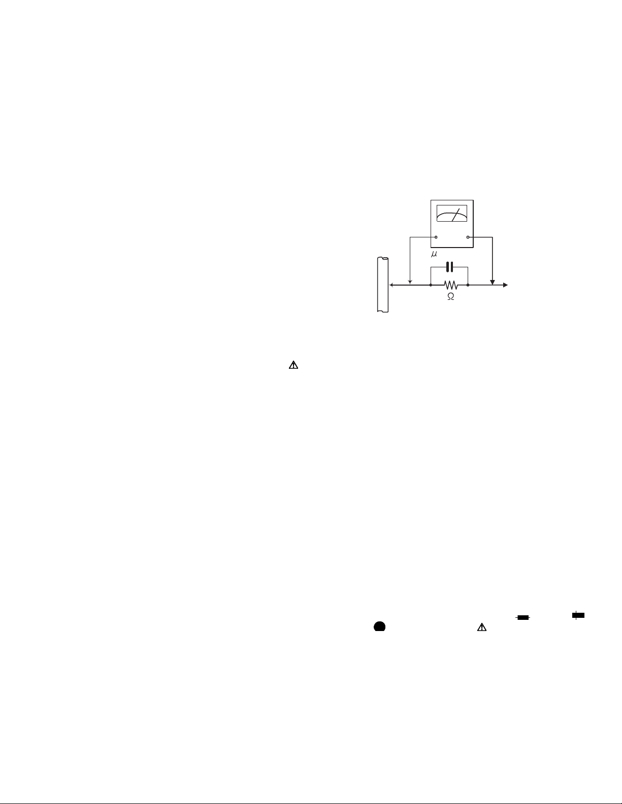
(5) Leakage shock hazard testing
After reassembling the product, always perform an isolation check on the exposed metal parts of the product (antenna terminals, knobs, metal cabinet, screw heads,
headphone jack, control shafts, etc.) to be sure the product
is safe to operate without danger of electrical shock.Do not
use a line isolation transformer during this check.
• Plug the AC line cord directly into the AC outlet. Using a
"Leakage Current Tester", measure the leakage current
from each exposed metal parts of the cabinet, particularly any exposed metal part having a return path to the
chassis, to a known good earth ground. Any leakage current must not exceed 0.5mA AC (r.m.s.).
• Alternate check method
Plug the AC line cord directly into the AC outlet. Use an
AC voltmeter having, 1,000Ω per volt or more sensitivity
in the following manner. Connect a 1,500Ω 10W resistor
paralleled by a 0.15µF AC-type capacitor between an ex-
posed metal part and a known good earth ground.
Measure the AC voltage across the resistor with the AC
voltmeter.
Move the resistor connection to each exposed metal
part, particularly any exposed metal part having a return
path to the chassis, and measure the AC voltage across
the resistor. Now, reverse the plug in the AC outlet and
repeat each measurement. Voltage measured any must
not exceed 0.75 V AC (r.m.s.). This corresponds to 0.5
mA AC (r.m.s.).
AC VOLTMETER
(Having 1000
ohms/volts,
or more sensitivity)
0.15 F AC TYPE
Place this
probe on
1500 10W
Good earth ground
1.2 Warning
(1) This equipment has been designed and manufactured to
meet international safety standards.
(2) It is the legal responsibility of the repairer to ensure that
these safety standards are maintained.
(3) Repairs must be made in accordance with the relevant
safety standards.
(4) It is essential that safety critical components are replaced
by approved parts.
(5) If mains voltage selector is provided, check setting for local
voltage.
1.3 Caution
Burrs formed during molding may be left over on some parts
of the chassis.
Therefore, pay attention to such burrs in the case of preforming repair of this system.
1.4 Critical parts for safety
In regard with component parts appearing on the silk-screen
printed side (parts side) of the PWB diagrams, the parts that are
printed over with black such as the resistor ( ), diode ( )
and ICP ( ) or identified by the " " mark nearby are critical
for safety. When replacing them, be sure to use the parts of the
same type and rating as specified by the manufacturer.
(This regulation dose not Except the J and C version)
each exposed
metal part.
(No.MB205)1-3
Page 4
1.5 Preventing static electricity
.
Electrostatic discharge (ESD), which occurs when static electricity stored in the body, fabric, etc. is discharged, can destroy the laser
diode in the traverse unit (optical pickup). Take care to prevent this when performing repairs.
1.5.1 Grounding to prevent damage by static electricity
Static electricity in the work area can destroy the optical pickup (laser diode) in devices such as laser products.
Be careful to use proper grounding in the area where repairs are being performed.
(1) Ground the workbench
Ground the workbench by laying conductive material (such as a conductive sheet) or an iron plate over it before placing the
traverse unit (optical pickup) on it.
(2) Ground yourself
Use an anti-static wrist strap to release any static electricity built up in your body.
(caption)
Anti-static wrist strap
1M
(3) Handling the optical pickup
• In order to maintain quality during transport and before installation, both sides of the laser diode on the replacement optical
pickup are shorted. After replacement, return the shorted parts to their original condition.
(Refer to the text.)
• Do not use a tester to check the condition of the laser diode in the optical pickup. The tester's internal power source can easily
destroy the laser diode.
1.6 Handling the traverse unit (optical pickup)
(1) Do not subject the traverse unit (optical pickup) to strong shocks, as it is a sensitive, complex unit.
(2) Cut off the shorted part of the flexible cable using nippers, etc. after replacing the optical pickup. For specific details, refer to the
replacement procedure in the text. Remove the anti-static pin when replacing the traverse unit. Be careful not to take too long a
time when attaching it to the connector.
(3) Handle the flexible cable carefully as it may break when subjected to strong force.
(4) I t is not possible to adjust the semi-fixed resistor that adjusts the laser power. Do not turn it.
1.7 Attention when traverse unit is decomposed
*Please refer to "Disassembly method" in the text for the pickup unit.
• Apply solder to the short land sections before the flexible wire is disconnected from the connecto on the servo board. (If the flexible
wire is disconnected without applying solder, the pickup may be destroyed by static electricity.)
• In the assembly, be sure to remove solder from the short land sections after connecting the flexible wire.
Conductive material
(conductive sheet) or iron palate
1-4 (No.MB205)
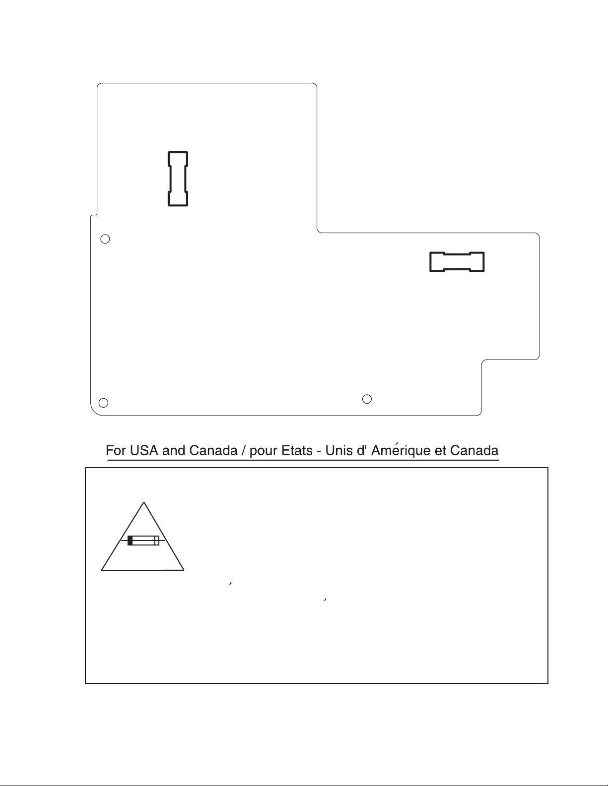
Caution: For continued protection against risk of
fire, replace only with same type 2.5 A/125 V for
F1000, 1.5 A/125 V for F1001.
This symbol specifies type of fast operating fuse.
Precaution: Pour eviter risques de feux, remplacez
le fusible de surete de F1000 comme le meme type
que 2,5 A/125 V, et 1,5 A/125 V pour F1001.
Ce sont des fusibles suretes qui functionnes rapide
^
Page 5
1.8 Importance administering point on the safety
Primary board
1.5A-125V
F1001
F1000
2.5A-125V
Caution: For continued protection against risk of
fire, replace only with same type 2.5 A/125 V for
F1000, 1.5 A/125 V for F1001.
This symbol specifies type of fast operating fuse.
Precaution: Pour eviter risques de feux, remplacez
le fusible de surete de F1000 comme le meme type
que 2,5 A/125 V, et 1,5 A/125 V pour F1001.
Ce sont des fusibles suretes qui functionnes rapide.
^
(No.MB205)1-5
Page 6

SECTION 2
SPECIFIC SERVICE INSTRUCTIONS
This service manual does not describe SPECIFIC SERVICE INSTRUCTIONS.
1-6 (No.MB205)
Page 7
SECTION 3
r
DISASSEMBLY
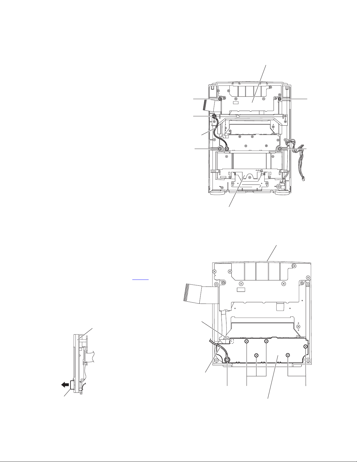
3.1 Main body section
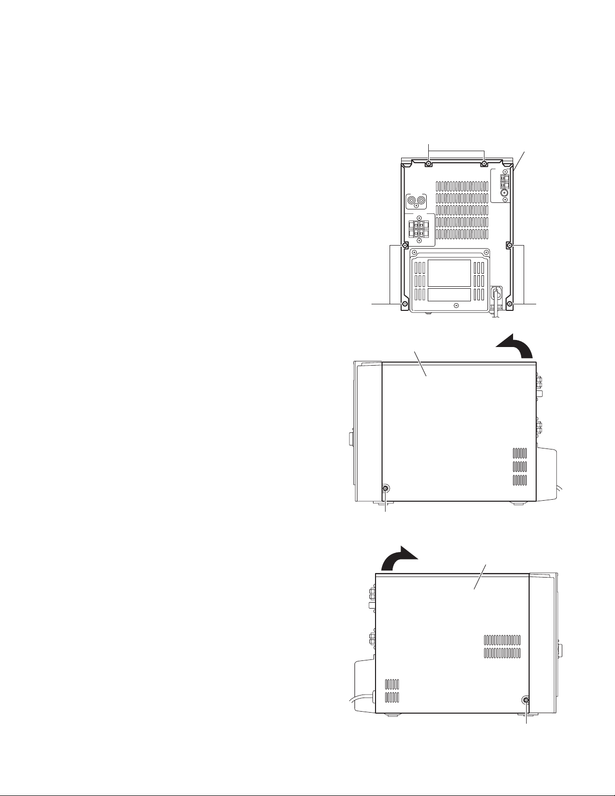
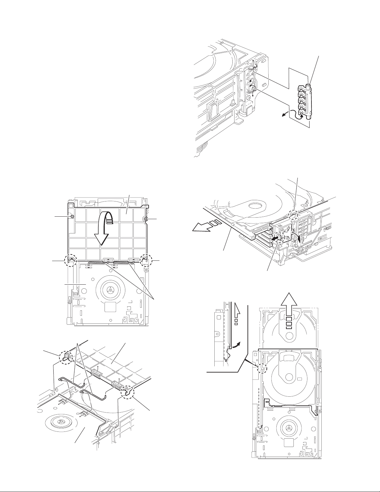
3.1.1 Removing the metal cover
(See Figs.1 to 3)
(1) From the back side of the main body, remove the six
screws A attaching the metal cover. (See Fig.1.)
(2) From the both sides of the main body, remove the two
screws B attaching the metal cover. (See Figs.2 and 3.)
(3) Remove the metal cover in the direction of the arrow while
extending the lower sections of the metal cover. (See
Figs.2 and 3.)
A
Metal cove
A
A
Fig.1
Metal cover
B
Fig.2
Metal cover
B
Fig.3
(No.MB205)1-7
Page 8
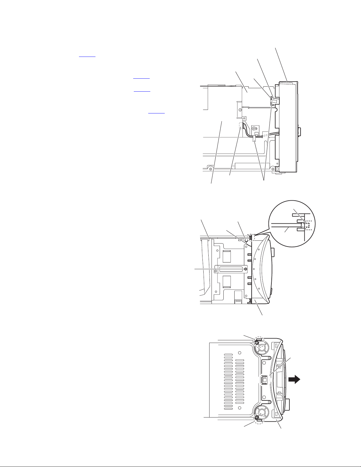
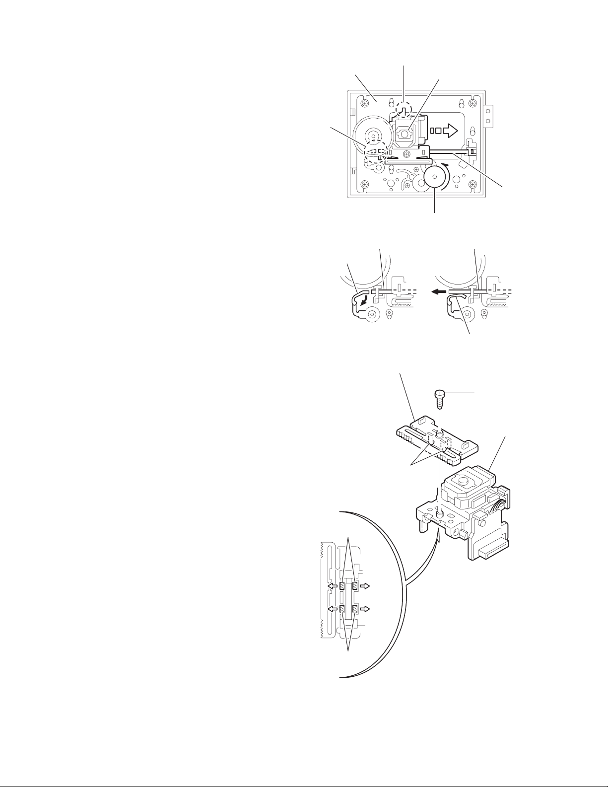
3.1.2 Removing the front panel assembly
(See Figs.4 to 6)
• Remove the metal cover.
(1) From the left side of the main body, disconnect the wire
from the connector CN104 on the power supply board.
(See Fig.4.)
Reference:
After connecting the wire to the connector CN104
wire with the spacer as before. (See Fig.4.)
(2) Disconnect the card wire from the connector CN700
micon board. (See Figs.4 and 5.)
Reference:
After connecting the card wire to the connector CN700
fix the card wire with the spacer as before. (See Fig.4.)
(3) From the top side of the main body, remove the screws C
attaching the front panel assembly. (See Fig.5.)
(4) From the bottom side of the main body, remove the two
screws D attaching the front panel assembly. (See Fig.6.)
(5) Release the two hooks a and hook b from the both and bot-
tom sides of the front panel assembly, and remove the front
panel assembly in the direction of the arrow. (See Fig.6.)
Reference:
When attaching the front panel assembly, fit the micon board
to the notch c on the back side of the front panel assembly.
(See Fig.5.)
, fix the
on the
Front panel assembly
Card wire
Micon board
CN700
,
CN104
Power supply board
Spacer
Fig.4
Micon board
C
c
CN700
Card wire
Micon board
Front panel assembly
Fig.5
a
b
1-8 (No.MB205)
D
a
Front panel assembly
Fig.6
Page 9
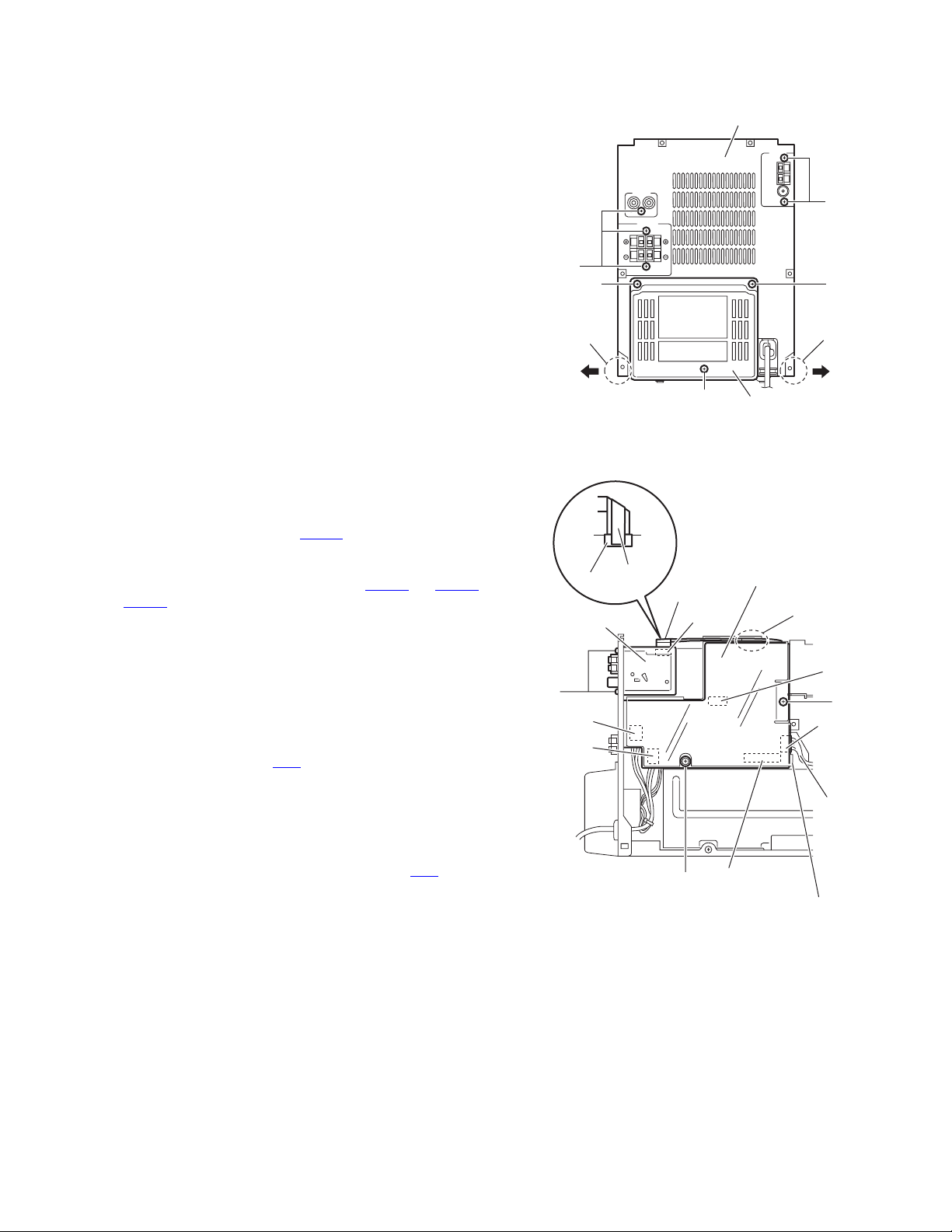
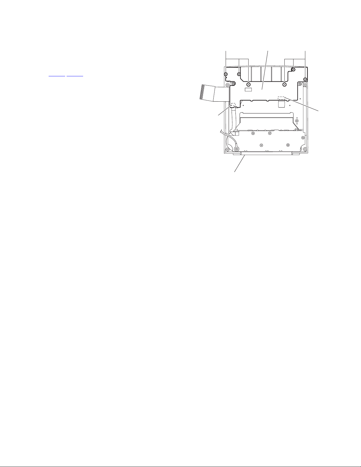
3.1.3 Removing the rear panel
(See Fig.7)
• Remove the metal cover.
(1) From the back side of the main body, remove the five
screws E attaching the rear panel.
(2) Remove the screw F attaching the rear cover.
(3) Remove the rear panel from the chassis while extending
the sections d of the rear panel in the direction of the arrow.
Reference:
When removing the rear cover, remove the screw F and two
screws F'.
E
F'
Rear panel
E
F'
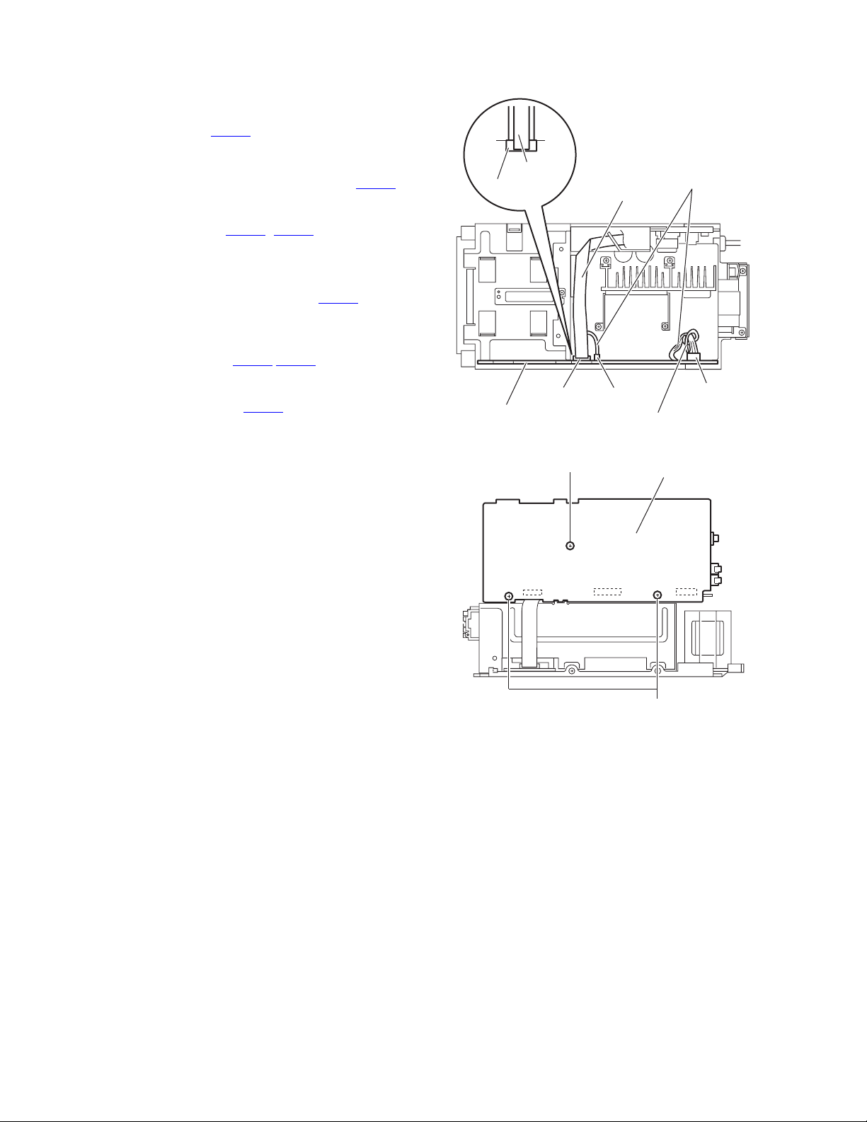
3.1.4 Removing the power supply board
(See Fig.8)
• Remove the metal cover.
(1) From the left side of the main body, remove the screw G
and screw H attaching the power supply board.
(2) Disconnect the connectors CN103
board toward this side.
(3) From the forward side of the power supply board, discon-
nect the wires from the connectors (CN100
).
CN104
Reference:
When attaching the screw G, attach the primary protector with
it.
3.1.5 Removing the tuner
(See Fig.8)
• Remove the metal cover.
(1) From the left side of the main body, disconnect the card
wire from the connector CN1
(2) From the back side of the main body, remove the two
screws J attaching the tuner.
Reference:
• After attaching the tuner, put the card wire on the section e
of the primary protector.
• When connecting the card wire to the connector CN1
card wire with the spacer as before.
on the power supply
to CN102,
on the tuner.
, fix the
J
CN101
CN100
d
CN1
Tuner
Spacer
F
Fig.7
Card wire
CN1
CN103
H
Fig.8
d
Rear cover
Power supply board
e
CN102
G
CN104
Wire
Primary protector
(No.MB205)1-9
Page 10
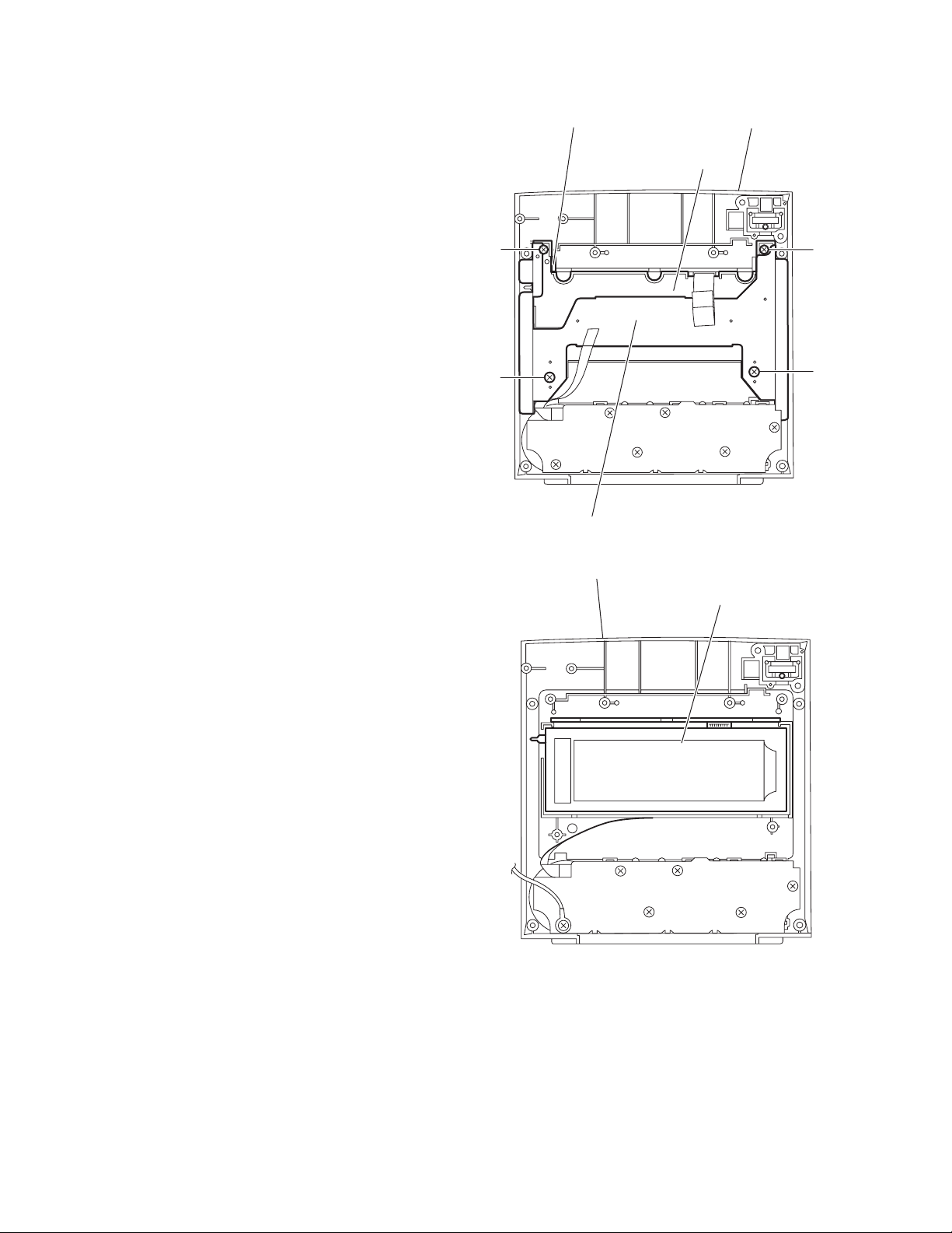
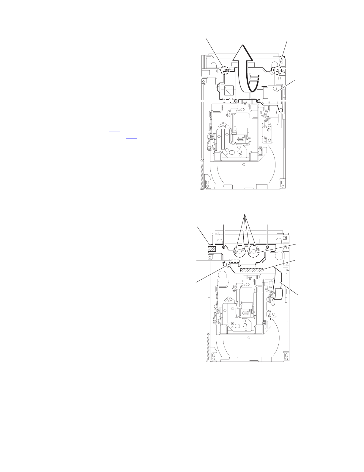
3.1.6 Removing the micon board
(See Figs.9 and 10)
• Remove the metal cover, front panel assembly and rear panel.
(1) From the top side of the main body, disconnect the card
wire from the connector CN766 on the micon board. (See
Fig.9.)
Reference:
When connecting the card wire to the connector CN766
fix the card wire with the spacer as before.
(2) From the forward side of the micon board, disconnect the
wire from the connectors (CN750
board. (See Fig.9.)
Reference:
When reassembling, fix the wire with the wire holder after connecting the wire to the connector CN760
micon board as before. (See Fig.9.)
(3) From the right side of the main body, remove the three
screws K attaching the micon board. (See Fig.10.)
(4) Disconnect the connectors (CN761
board toward this side. (See Fig.10.)
(5) From the forward side of the micon board, disconnect the
card wire from the connectors CN765
, CN760) on the micon
on the
,CN762) on the micon
. (See Fig.10.)
,
Micon board
CN766
Spacer
CN766
Card wire
CN750
Wire holder
Fig.9
Wires
CN760
CN765
K
CN762
Fig.10
Micon board
CN761
K
1-10 (No.MB205)
Page 11
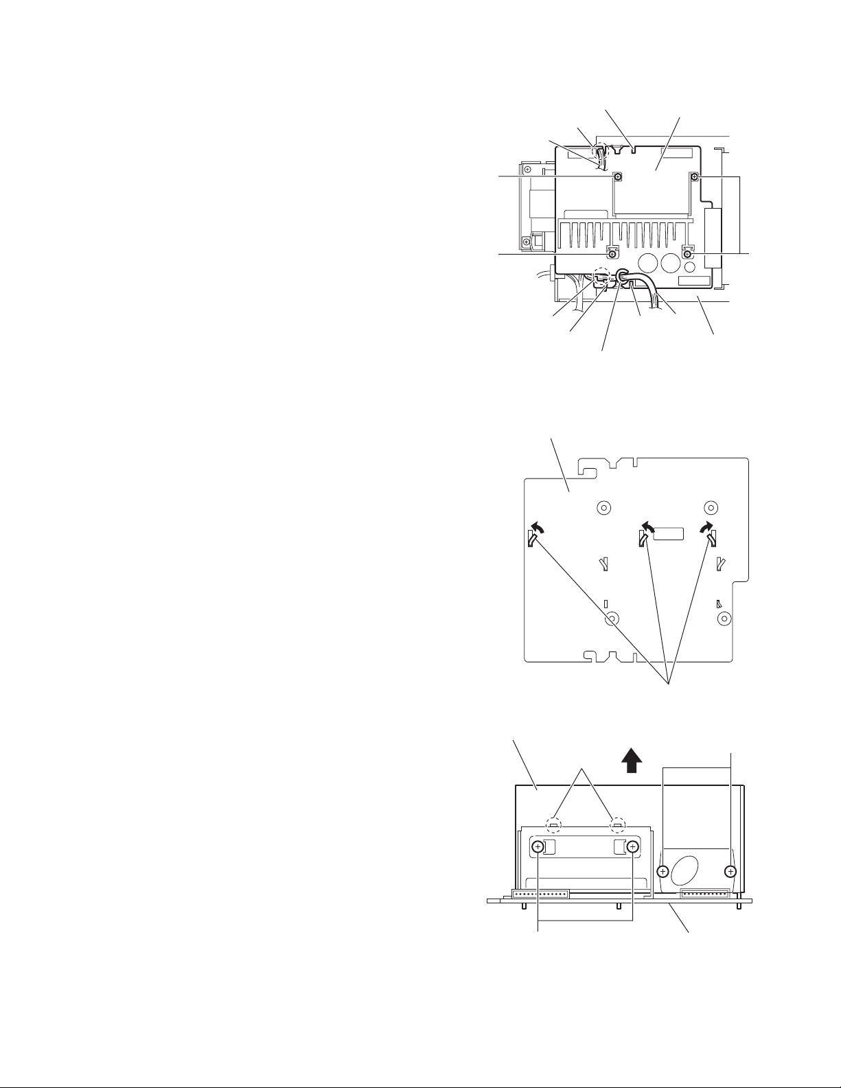
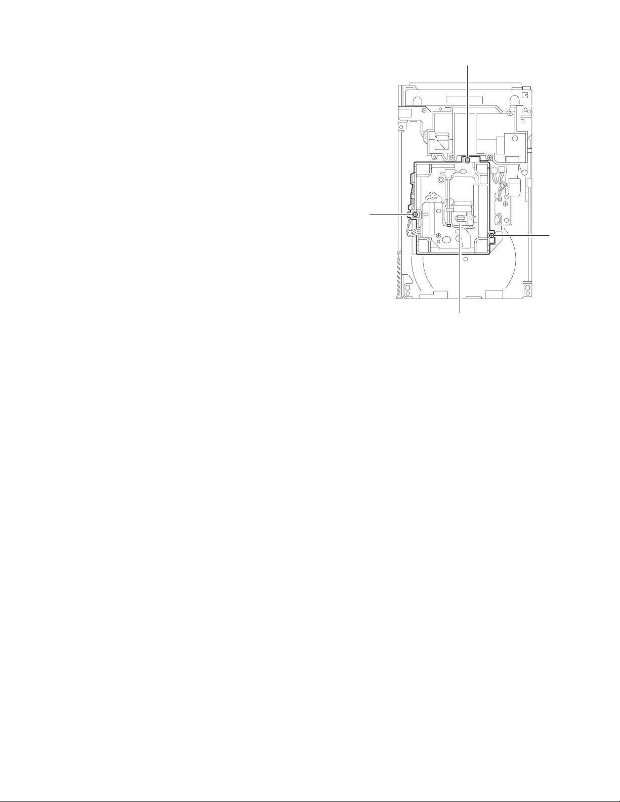
3.1.7 Removing the power amplifier board
(See Fig.11)
• Remove the metal cover, front panel assembly, rear panel,
power supply board and micon board.
(1) From the top side of the main body, remove the wire holder
and tie band fixing the wire 1.
(2) Remove the four screws L attaching the power amplifier
board.
Reference:
• When attaching the power amplifier board, align the sections
f of the main chassis in the slots of the main amplifier board.
• After attaching the power amplifier board, pass the wire 1
through the section g of the power amplifier board.
• When reassembling, fix the wire 1 with the wire holder and
new tie band as before.
• When reassembling, pass the wire 2 through the section h
of the power amplifier board.
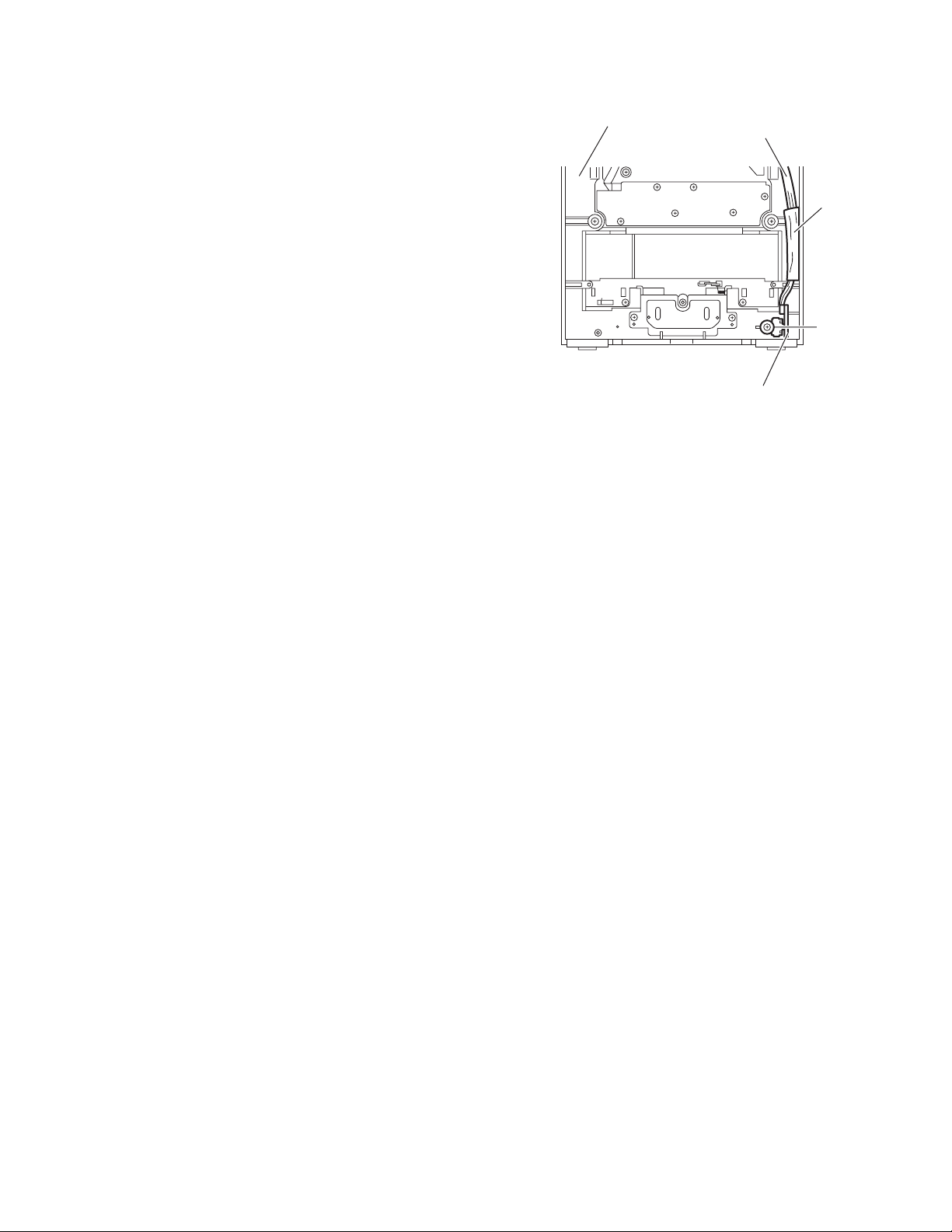
3.1.8 Removing the heat sink
(See Figs.12 and 13)
• Remove the metal cover, front panel assembly, rear panel,
power supply board, micon board and power amplifier board.
(1) From the reverse side of the power amplifier board, bend
the claws i of the heat sink in the direction of the arrow.
(See Fig.12.)
(2) From the forward side of the power amplifier board, remove
the four screws M attaching the heat sink. (See Fig.13.)
(3) Disengage the joints j and remove the heat sink in the di-
rection of the arrow. (See Fig.13.)
h
Wire 2
L
L
g
Tie band
Wire holder
Power amplifier board
f
Power amplifier board
Wire 1
f
Fig.11
L
Main chassis
Heat sink
M
i
Fig.12
M
j
Power amplifier board
Fig.13
(No.MB205)1-11
Page 12
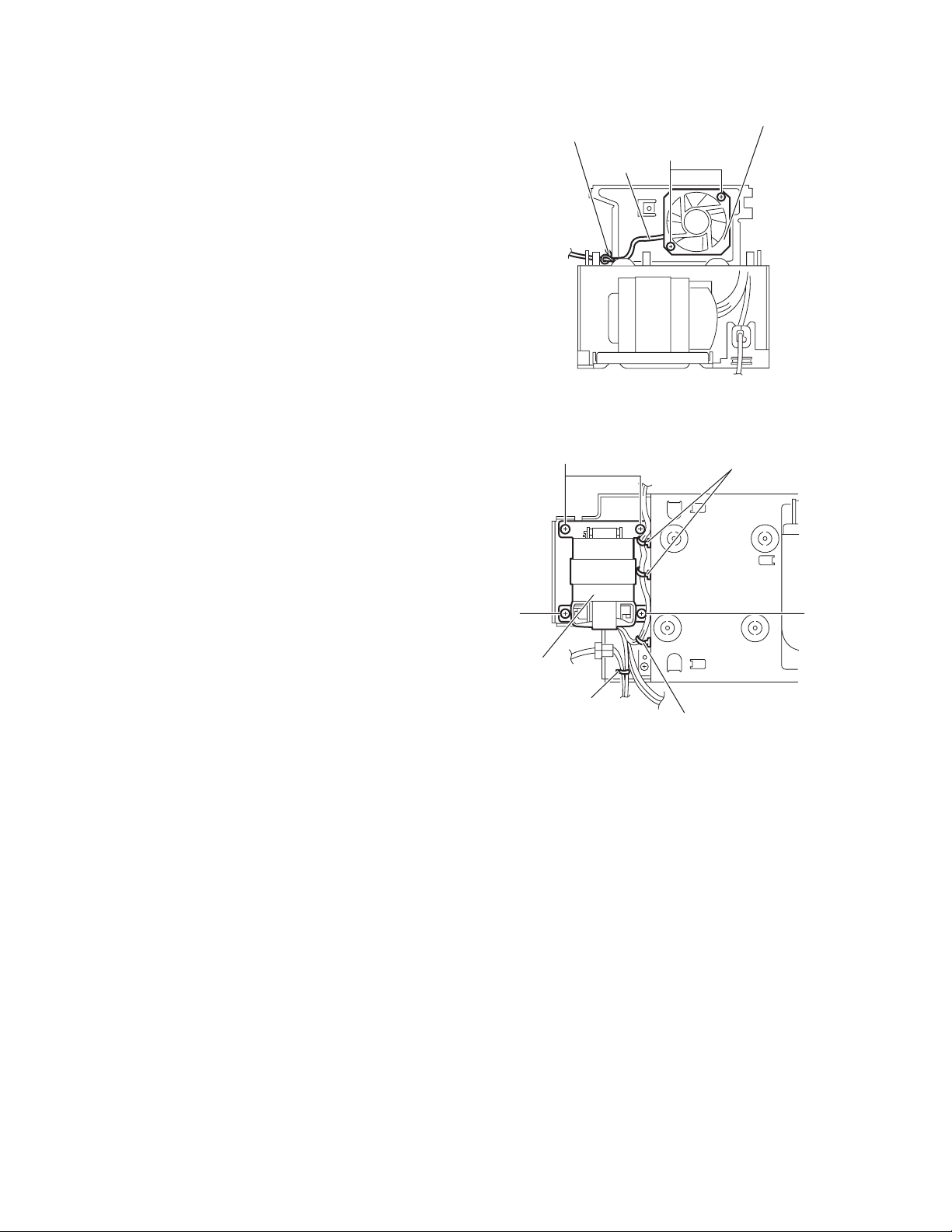
3.1.9 Removing the fan
(See Fig.14)
• Remove the metal cover, front panel assembly, rear panel,
power supply board, micon board and power amplifier board.
(1) From the back side of the main body, remove the wire hold-
er fixing the wire.
Reference:
After attaching the fan, fix the wire with the wire holder as
before.
(2) Remove the two screws N attaching the fan.
3.1.10 Removing the power transformer
(See Fig.15)
• Remove the metal cover, front panel assembly, rear panel,
power supply board, micon board and power amplifier board.
(1) From the top side of the main body, remove the wire hold-
ers fixing the wire.
(2) Remove the tie band.
(3) Remove the four screws P attaching the power transformer
and take out the power transformer from the main body.
Reference:
After attaching the power transformer, fix the wires with the
wire holders and new tie band as before.
P
Wire holder
P
Wire
Fan
N
Fig.14
Wire holders
P
Power
transformer
Tie band
Wire holder
Fig.15
1-12 (No.MB205)
Page 13
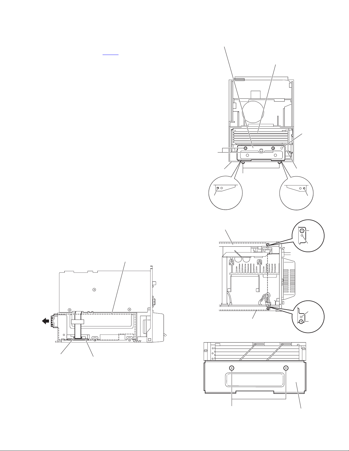
3.1.11 Removing the CD changer mechanism assembly
(See Figs.16 to 19.)
• Remove the metal cover and front panel assembly.
(1) From the right side of the main body, disconnect the card
wire from the connector CN651
board. (See Fig.16.)
(2) From the bottom side of the main body, remove the two
screws Q attaching the CD bracket (F) to the bottom chassis. (See Fig.17.)
Reference:
When attaching the CD bracket (F), align the projections
k of the bottom chassis in the holes of the CD bracket
(F). (See Fig.17.)
(3) From the front side of the main body, remove the two
screws R attaching the CD bracket (F) to the main chassis.
Reference:
When attaching the CD bracket (F), align the projection
m of the main chassis in the holes of the CD bracket (F).
(See Fig.17.)
(4) From the top side of the main body, remove the two screws
S attaching the CD changer mechanism assembly. (See
Fig.18.)
Reference:
Align the projections n on the bottom chassis in the holes
of the CD changer mechanism assembly before attaching the screws S. (See Fig.18.)
(5) Take out the CD changer mechanism assembly in the di-
rection of the arrow. (See Fig.16.)
Note:
When take out the CD changer mechanism assembly,
be careful not to damage the several parts on the CD
servo control board. (See Fig.16.)
(6) From the back side of the CD changer mechanism assem-
bly, remove the two screws T attaching the CD bracket (R).
(See Fig.19.)
CD changer mechanism assembly
on the CD servo control
CD bracket (F)
CD changer mechanism assembly
R
Bottom chassis
Q
k
Fig.17
CD changer mechanism assembly
m
Main chassis
k
S
n
CN651
CD servo control board
Fig.16
Bottom chassis
Fig.18
T
Fig.19
n
S
CD bracket (R)
(No.MB205)1-13
Page 14
3.2 Front panel assembly
• Remove the metal cover and front panel assembly.
3.2.1 Removing the front assembly section
(See Fig.20)
(1) From the inside of the front panel assembly, remove the
screw U attaching the earth wire.
Reference:
When attaching the screw U, attach the earth wire with it.
(2) Remove the four screws V attaching the front assembly
section.
(3) Take out the front assembly section from the main body.
V
U
Earth wire
Front assembly section
V
3.2.2 Removing the switch board
(See Figs.21 and 22)
• Remove the front assembly section.
(1) From the front side the front assembly section, pull out the
volume knob in the direction of the arrow. (See Fig.21.)
(2) From the inside of the front assembly section, remove the
five screws W and screw W' attaching the switch board.
(See Fig.22.)
(3) Disconnect the card wire from the connector CN510
switch board. (See Fig.22.)
Reference:
When attaching the screw W', attach the earth wire with
it. (See Fig.22.)
(4) Take out the switch board from the front assembly section.
(See Fig.22.)
Front assembly section
on the
V
Front panel assembly
CN510
V
Fig.20
Front assembly section
Volume knob
1-14 (No.MB205)
Fig.21
Earth wire
W' W
W
Switch board
Fig.22
Page 15
3.2.3 Removing the back light board
(See Figs.23)
• Remove the front assembly section.
(1) From the inside of the front assembly section, remove the
six screws X attaching the back light board.
(2) Take out the back light board from the front assembly sec-
tion and disconnect the card wires from the connectors
(CN551
,CN552) on the back light board.
Back light board
XX
CN551
Front assembly section
CN552
Fig.23
(No.MB205)1-15
Page 16
3.2.4 Removing the FL board
Y
Y
(See Figs.24 and 25)
• Remove the front assembly section and back light board.
(1) From the inside of the front assembly section, remove the
four screws Y attaching the lens holder. (See Fig.24.)
(2) Take out the lens holder with the LED lens and cover sheet.
(See Fig.24.)
(3) Take out the FL board from the front assembly section.
(See Fig.25.)
LED lens
Lens holder
Cover sheet
Fig.24
Front assembly section
Front assembly section
Y
Y
FL board
1-16 (No.MB205)
Fig.25
Page 17
3.2.5 Removing the headphone jack board
r
(See Fig.26)
(1) From the inside of the front panel assembly, remove the
screw Z attaching the headphone jack board.
(2) Take out the headphone jack board from the front panel as-
sembly.
Reference:
After attaching the headphone jack board, fix the wire with the
spacer as before.
Front panel assembly
Wire
Space
Z
Headphone jack board
Fig.26
(No.MB205)1-17
Page 18
3.3 CD changer mechanism
r
3.3.1 Removing the tray assembly
(See Fig.1 ~ 5)
(1) Remove the two screws A from the top cover and release
the two joints a on both sides of the body.
(2) Remove the top cover with the two rods attached to the top
cover and lifter assembly respectively.
(3) Remove the open det lever on the left side of the body.
(4) Push part b of the slide (R) assembly on the right side of
the body to unlock the tray assembly. Draw out the trays to-
ward the front.
Attention:
The tray can be locked if all tray assemblies are attached.
(5) From top of the body, move the stopper tab c in the direc-
tion of the arrow and release. Pull out the tray assemblies
from the body.
Caution:
Remove the tray assembly from top tray 5 in order.
Attention:
When reattaching the sub tray of the tray assembly, or when
removing the CD remaining inside, refer to another section.
Top cover
Open det leve
Fig.3
c
A
a
Lifter assembly
a
Rod
Fig.1
Top cover
A
a
Tray assembly
(Tray 5)
b
Fig.4
Rod
Lifter assembly
1-18 (No.MB205)
a
Fig.2
Fig.5
Page 19
3.3.2 Removing the servo control board
(See Fig.6 ~ 9)
Caution:
Solder the short-circuit point on the pickup before disconnecting the card wire extending from the pickup. If you do not follow
this instruction, the pickup may be damaged.
(1) Disconnect the card wire from connector CN251
wire from connector CN252
vo control board on the bottom of the body. Disconnect the
wire from joint d.
(2) Solder the short round point on the flexible board of the pick
up.
(3) Remove the four screws B and turn the servo control board
as shown in the figure.
(4) Disconnect the card wire from connector CN601
servo control board.Caution: Unsolder the short-circuit
point after reassembling.
Caution:
When reassembling, twist the wires to be connected to connector CN252
3.3.3 Removing the switch board
(See Fig.9)
(1) Disconnect the wires from connector CN252
on the servo control board.
(2) Remove the screw C attaching the switch board.
(3) Release the wires from the slot e of the switch board.
Caution:
When reassembling, let the wires through the slot e of the
switch board and twist them twice.
and CN253 twice.
Servo control board
, CN253 and CN602 on the ser-
and each
on the
and CN253
B
Card wire
Short round
Flexible board
Pickup
Fig.7
Card wire
CN601
CN602
d
B
Fig.6
CN253
CN252
B
CN251
Switch board
Servo control board
Fig.8
Servo control board
CN253
e
CN252
Switch board
C
Fig.9
(No.MB205)1-19
Page 20
3.3.4 Removing the motor board
(See Fig.10 , 11)
• Prior to performing the following procedure, remove the servo
control board.
(1) Turn over the body and remove the two screws D. Move
the CD module bkt. in the direction of the arrow to release
two joints f.
(2) Unsolder the four soldered parts on the motor of the motor
board.
Caution:
If removing the motor board with the motor, you should
remove the screws attaching the motor from top of the
body(Refer to another section).
(3) Remove the two screws E attaching the motor board.
(4) Remove the spacer fixing the motor board and tray switch
board, and disconnect connector CN2
(5) Disconnect the card wire from connector CN1
board.
Caution:
When reconnecting the card wire, let the card wire through the
slot g of the motor board and attach it to the bottom of the body
using a double tape.
on the motor board.
on the motor
f
f
CD Module
braket
DD
Fig.10
Spacer
Soldering point
CN2
CN1
g
E
E
Motor
Double
face tape
Card wire
Fig.11
1-20 (No.MB205)
Page 21
3.3.5 Removing the CD tramecha assembly
(See Fig.12)
• Prior to performing the following procedure, remove the servo
control board.
(1) Turn over the body and remove the three screws F attach-
ing the tramecha.
F
F
F
CD Tramecha assembly
Fig.12
(No.MB205)1-21
Page 22
3.3.6 Removing the pickup
(See Fig.13 , 14)
• Prior to performing the following procedure, remove the servo
control board and CD tramecha assembly.
(1) From top of the CD tramecha assembly, turn the cam gear
in the direction of the arrow to move the pickup assembly
outward.
(2) Push down the stopper h in the direction of the arrow and
pull out the shaft.
(3) Release the joint i of the pickup assembly and mecha
base.
(4) Remove the screw G attaching the CD rack. Release the
four tabs j at the bottom of the CD rack.
Mecha base
h
Stopper
i
Pickup assembly
Shaft
Cam gear
ShaftShaft
Stopper
Fig.13
CD lack
G
Pickup
j
j
1-22 (No.MB205)
j
Fig.14
Page 23

3.3.7 Removing the side (L)/ tray switch board
(See Fig.15 ~ 17)
• Prior to performing the following procedure, remove the tray
assembly.
(1) Remove the two screws H attaching the side (L) on top of
the body.
(2) From the side of the body, remove the spacer fixing the tray
switch board and motor board. Disconnect connector CN3
on the tray switch board and detach the side (L) upward.
(3) Remove the screw J attaching the tray switch board.
(4) Push the joint tab k of the side (L) in the direction of the ar-
row and remove the tray switch board outward, then re-
lease joint l.
H
Side (L)
H
Fig.15
H
H
Side (L)
CN3
Spacer
Side (L)
Fig.16
k
Tray switch board
Fig.17
l
J
(No.MB205)1-23
Page 24

3.3.8 Removing the side (R) assembly
(See Fig.18 ~ 22)
• Prior to performing the following procedure, remove the tray
assembly.
(1) Push and release the two tabs m of the gear cover through
the two notches inside the side (R) assembly. Remove the
gear cover outward.
(2) Remove the spring attached to part n of the hook on the
right side of the body.
(3) From top of the body, turn the 1 gear clockwise to move the
elevator cam rearward.Move the two slots o and joint p of
the elevator cam as shown in Fig.21 and remove the elevator cam outward.
(4) Remove the three screws K and detach the side (R) up-
ward.
Caution:
When reattaching the side (R) assembly, make sure to fit the
shaft (part q) into the slot of the select lever.
Side (R) assembly
m
Fig.20
K
Side (R)
assembly
K
Side (R) assembly
K
Fig.18
q
Spring
n
Elevator cam
o
o
p
Fig.21
K
Side (R) assembly
1 gear
Gear cover
1-24 (No.MB205)
Sprihg
K
n
Fig.22
Elevator com
Fig.19
Page 25

3.3.9 Removing the lifter assembly
(See Fig.23 ~ 27)
• Prior to performing the following procedure, remove the tray
assembly and side (L)/ side (R) assembly.
(1) From top of the body, turn the 1 gear clockwise to move the
lifter assembly upward as shown in Fig.24.
(2) From top of the body, turn the 2 gear clockwise to move the
hook toward the front until it stops.
(3) Move the hook stopper in the direction of the arrow while
pushing the tab r of the hook stopper to unlock it. Release
four joints s to detach from the rack holder.
Release the rod from part t.
(4) Turn the 1 gear clockwise again to move the lifter assembly
upward.
(5) Remove the lifter assembly from the body upward at posi-
tion u where the four pins on the right and left sides of the
lifter assembly fit to the notches of the v.
Move the lifter assembly toward the front and release from
the hook.
2 gear
1 gear
Hook
t
s
Rod
s
s
r
s
Hook stopper
Fig.25
Lifter assembly
1 gear
u u
Hook stopper
Hook
2 gear
Fig.23
1 gear
Lifter
assembly
Lifter assembly
v
Lifter assembly
Fig.26
u
u
Hook stopper
Hook
Fig.24
v
Fig.27
(No.MB205)1-25
Page 26

3.3.10 Removing the rack holder assembly/ sensor assembly
(See Fig.28 ~ 33)
• Prior to performing the following procedure, remove the tray
assembly, side (L)/ side (R) assembly, lifter assembly.
Attention:
If the slide gear of the body places at joint w of the rack holder
assembly, turn the 1 gear counterclockwise to move the slide
gear toward the front. Remove the rack holder assembly.
(1) Remove the three screws J attaching the rack holder as-
sembly. Release joint w from the notch.
Caution:
When reattaching the rack holder assembly, do not nip
the wire x extending from the sensor assembly.
(2) Remove the two screws M attaching the sensor assembly.
(3) Move the sensor assembly in the direction of the arrow to
release from the slot at joint y.
(4) Remove the spring attached to the bottom of the sensor as-
sembly from the boss z on the sensor slider.
(5) Remove the screw N and O attaching the sensor board and
SV resister respectively.If necessary, unsolder the sensor
board.
Caution:
When reattaching the SV resister, attach the sensor slider to
the sensor bracket and fit the lever on the bottom of the SV resister into slot a’ of the sensor slider.
Caution:
When reattaching the rack holder assembly, turn the 1 gear
clockwise to move the slide gear and slide lever inside the
body rearward.
• Let the wire extending from the sensor assembly through notch
x to the bottom of the body.
• Fit pin c’of the slide lever into hole b’ of the sensor slider on
the bottom of the sensor assembly while attaching the spring
to the boss z of the sensor slider.
• Engage joint y of the sensor assembly to the notch of the body.
Rack holder
assembly
Rack holder
assembly
L
w
L
1 gear
x
L
Fig.28
Rack holder
assembly
1-26 (No.MB205)
w
w
Fig.29
Page 27

x
O
Soldering
SV resister
N
Sensor board
point
M
z
M
Sensor slider
y
a'
Fig.30
b'
Sensor assembly
Spring
Spring
a'
Slide gear
Sensor braket
Sensor slider
Fig.32
M
Sensor assembly
M
y
b'
z
z
Fig.31
c'
Spring
Fig.33
Slide lever
(No.MB205)1-27
Page 28

3.3.11 Removing the motor
r
(See Fig.34 ,35)
• Prior to performing the following procedure, remove the servo
control board and top cover.
Attention:
You need not to remove the tray assembly, and in such case,
move it.
(1) Remove the two belts on top of the body.
(2) Remove the four screws N attaching the motor.
(3) Remove the motor board from the bottom of the body.
(Refer to the section “Removing the motor board”.)
Attention:
When removing the motor board with the motor, you need not
to unsolder four soldered parts.
Caution:
When reattaching the motor, turn the side where the label
should be put to the front side.
Motor
Moto
NN
Belt
Fig.34
Label
Belt
Fig.35
1-28 (No.MB205)
Page 29

3.3.12 Taking out the CD in play mode
r
(See Fig.36 ~ 39)
Attention:
Refer to “Removing the tray assembly”.
(1) Remove the top cover upward.
(2) Unlock the tray assembly and draw out the tray assembly
toward the front.
(3) From top of the body, turn the 1 gear clockwise to move the
lifter assembly upward.
(4) From top of the body, turn the 2 gear clockwise to move the
sub tray remaining inside the lifter assembly toward the
front, then pull out.
(5) Take out the CD on the sub tray.
(6) After clearing away the CD, insert the sub tray into the main
tray.
Caution:
When reattaching the sub tray, move the tray stopper on
the bottom of the main tray in the direction of the arrow
to lock the sub tray certainly.
(7) Push the tray assembly toward the body and reattach.
Tray assembly
Tray assembly
Tray stopper
Sub tray
Fig.37
Main tray
2 gear
1 gear
Sub tray
Sub tray
Fig.38
Fig.36
Tray stoppe
Fig.39
(No.MB205)1-29
Page 30

SECTION 4
ADJUSTMENT
This service manual does not describe ADJUSTMENT.
1-30 (No.MB205)
Page 31

SECTION 5
TROUBLESHOOTING
This service manual does not describe TROUBLESHOOTING.
(No.MB205)1-31
Page 32

VICTOR COMPANY OF JAPAN, LIMITED
AV & MULTIMEDIA COMPANY AUDIO/VIDEO SYSTEMS CATEGORY 10-1,1chome,Ohwatari-machi,Maebashi-city,371-8543,Japan
(No.MB205)
Printed in Japan
WPC
Page 33

SCHEMATIC DIAGRAMS
COMPACT COMPONENT SYSTEM
FS-S57
CD-ROM No.SML200404
Area suffix
J ----------------------------- U.S.A.
C -------------------------- Canada
Contents
Block diagram
Standard schematic diagrams
Printed circuit boards
COPYRIGHT 2004 VICTOR COMPANY OF JAPAN, LTD.
2-1
2-3
2-15 to 20
No.MB205SCH
2004/4
Page 34

In regard with component parts appearing on the silk-screen printed side (parts side) of the PWB diagrams, the
parts that are printed over with black such as the resistor ( ), diode ( ) and ICP ( ) or identified by the " "
mark nearby are critical for safety.
(This regulation does not correspond to J and C version.)
Page 35

< MEMO >
Page 36

0
R
H
U
m
Block diagram
CD servo and CD system control section
A,B
C,D
E,F
CN601 CN602
LD,MD
CD
PICK UP
T+/F+/-
REST SW
FEED
MOTOR
SPINDLE
MOTOR
SM+/FM+/-
/REST_SW
IC601
RF
&
SERVO
AMP.
FOCUS
TRACKING
SPINDLE
BTL AMP.
/DR_MUTE
PC1,PC2
FM ANT
AM ANT
IC801
FEED
CN3 CN2
TBAL,FBAL
TE,FE,GCTL
/RFDET
OFT,BDO
ARF,RFENV
TRV,TRD
FOD,SPINDLE
AD0 to AD10
D0 to D3
IC671
DRAM
IC682
/CAS
/RAS
IC681
/WE
FM/AM tuner unit section Signal processing and syste
IC1
FM/AM
TUNER
TUL
TUR
9V
TUDIN
TUDOUT
CE,CLK
CN1
CN766
Q760
Q7601
TUNE
SWITC
FT
IC651
DIGITAL
SERVO
&
OUTL
OUTR
SDATAIN
SDATAOUT
TUCLK
TUCE
PROCESSOR
IC900
SYSTEM
MICON
/DCAS
/DRAS
/DWE
CASCNT
RASCNT
WECNT
TXTD
TXTCK
/RST_DSP
MON
FLAG
DQSY
BLKCK
MLD
MDATA
STAT
MCLK
TXD0
RXD0
RESET
CN765
CN651
CDL,CDR
CDCMD
CDRST
CDSTAT
Q7700,Q7701
TWIN
INVERTER
BUFFER
2-1
CD tray control section
IC1
TRAY MOTOR DRV.
IC2
POSITION MOTOR DRV.
CD tray switch
section
CN3
SW1 to SW6
SWITCH
SW8
SWITCH
IC1
POSITION
SENSOR
TR_OP
TR_CL
POS_UP
POS_DOWN
S.TR_ST
SW7
SWITCH
CN2
TR1_CL to TR5_CL
M.TR_OP
CN1
S.TR_END
L.SENSOR
CN251CN252 CN253
IC251
UNIT
MICON
IC201
EEPROM
E2PSDA
E2PSCL
AUX.
INPUT
TO
FAN
CN750
Q7500,Q7501
J2100
AUXL,AUXR
CDSTAT
FANON
FAN
DRIVER
Page 37

system control section
Q7600
Q7601
TUNER
WITCH
FTUNER
H/PSW
INHB
SPKRLY
Q7801
Q7802
SPEAKER
CIRCUIT
TUL
TUR
RY200
OUTL
OUTR
J2000
SPEAKER
OUTPUT
CN760
Power transformaer
T1101
TRANS
CN102
DIODE
BRIDGE
Primary section
CN101
T1100
TRANS
Q1100
Q1200 to Q1202
US6V REG.
CN100
AC
INPUT
00
EM
ON
VOLDA
VOLC K
VOLC E
/PRT,/SMUTE
POUTRLY
SPKRLY
VOLUME
CDL
CDR
AUXL
AUXR
/SMUTE
POUTRLY
H/PSW,INHB
IC901
& HPF
F1,F2
FLVH
/PRT
SIGL
SIGR
US6V
US10V
US8V
US3.3V
CN352
CN762CN761
CN351
POUTRLY
CN103
CN350
H/PL
H/PR
OUTL,OUTR
SIGL,SIGR
/PRT
Headphone
W5600
CN104
H/PL,H/PR
H/PSW
Q3200 to Q3202
H/P MUTING
Q3100 to Q3102
SYSTEM MUTE
/SMUTE
US3.3V
INHB,H/PSW
POUTRLY,US6V
IC343
US3.3V
REG.
J5600
HEADPHONE
JACK
Power amplifier section
+VH
-VH
IC340
POWER
AMP.
Q3105 to Q3107
PROTECTOR
US10V
IC341
US10V
S2
REG.
US8V
IC342
US8V
S2
REG.
POWERKEY
KEY1,KEY2
REM,VOLM,VOLP
FLDATA,FLSTB
FLBK,FLCLK
L-LED
C-LED
R-LED
Q7400 to Q7402
LED DRIVER
LEDCTL
LED CTL
Q7550
L-LED
C-LED
R-LED
LEDRED
LEDGREEN
CN700
CN550
POWERKEY
LEDRED
LEDGREEN
REM
REMSENSOR
S5200
TOP SWITCH
POWER
LED
IC520
LLED
CLED
RLED
DISPLAY
BACK
LIGHT
User key control sectionSource selector switch section
CN551
CN510
FL display section
CN552
FLDATA,FLSTB
CN570
FLVH,FLBK
FLCLK,F1,F2
VOLM
VOLP
KEY1
S5100 to S5116
KEY2
KEY MATRIX
J5100
VOLUME
DI570
FL DISPLAY
2-2
Page 38

Standard schematic diagrams
2
Primary and power amplifier section
IC340
STK432-070
R3100
4.7K
R3101
4.7K
C3100C3101
R3102
20K
Q3101
2SC3576-JVC-T
100P100P
R3104
10K
10/35
C3103
10/35
4.7/50
C3102
C3104
R3106R3107
47K47K
R3103
Q3100
R3105
10K
220
KRA102M-T
Q3102
2SC3576-JVC-T
C3105
100P
C3109
R3109
R3108
C3107
10P
47/50
820UNF( 1/4)
C3106
R3110
R3111
C3110C3111
R3112
33K
MTZJ9.1B-T2
10/50
L3100
0.39
10UNF( 1/4W)
10UNF( 1/4W)
0.10.1
C3112
0.22
R3113
0.22
R3114
220
R3116
R3115
100
C3114
D3100
C3113 C3116
0.022 0.022
Q3103
KTA1268/GL/-T
D3101
10K
R3117
2.2K
R3118
0.022
10/50
R3119
C3115
10/50
MTZJ9.1B-T2
D3102
R3120
R3121
2202.2K
100
0.22
R3123
D3104
R3122
R3124
0.22
C3117
Q3104
KTA1268/GL/-T
10K
10/50
L3101
R3125
0.39
R3138
C3119C3120
R3126
C3118
100P
10UNF( 1/4W)
R3127
C3121
10P
10UNF( 1/4W)
10UNF( 1/4W)
0.10.1
C3000
2200/502200/50
C3002
C3001
4.7K
R3150
B3010
Q3105
C3122
R3133
R3129
82K
R3128
47/50
120K
C3123
22/50
820UNF( 1/4)
R3130
10K
KTC3199/GL/-T
C3124
0.022
R3132
4.7FR( 1/4W)
R3134
100K
47K47K
R3131
100K
R3137
10K
Q3106
KTC3199/GL/-T
C3126
R3135
47/35
100K
C3125
Q3107
KTA1267/YG/-T
22/50
D3103
R3136
1.2K
2200/25
2-3
(SHEET 2)
NI
L3200
B3007
CN352
QGB2510K2-09
R3200
R3201
NI
2.7k
R3300
0.47
IC343
PQO33RDO1SZ
C3306
TH332
C3304
100/16
R3311
R3310
QAD0015-103Z
D3304
100/16
MTZJ3.6B-T2
C3300
10/50
C3301
10/50
D3300
IC341
KIA7810API
MTZJ11C-T2
10K
R3301R3302
10K
D3301
QGB2510K2-12
CN351
IC342
KIA7808API
R3303
0.33
NI
B3006
10K
10/50
D3302
R3304R3305
MTZJ11C-T2
18K
D3303
10/50
C3302
C3303
C3200
R3204
220
4.7/50
R3206
47K
Q3200
R3207 R3208
10K 10K
KRA102M-T
820
Q3201
820
2SC3576-JVC-T
Q3202
2SC3576-JVC-T
R3202
R3203
820
NI
B3008
L3201
820
(SHEET
Page 39

C3002
2200/25
CN350
S2
EP300
QNZ0136-001Z
QGB2510K2-14
CN103
QGB2510J1-14
+VH
AMPG
-VH
S2G
S2
DG
US10V
US6V
POUTRLY
INHB
H/PR
H/PGND
H/PL
H/PSW
C1303
0.1/50
0.1/50
1N5402M-20
D1303
1N5402M-20
D1302
1N5402M-20
C1302
0.1/50
C1300
D1300
D1301
1N5402M-20
C1301
0.1/50
C1403
0.1/50
1N4003S-T5
D1403
1N4003S-T5
1N4003S-T5
0.1/50
D1402
C1402
0.1/50
C1400
D1400
D1401
1N4003S-T5
C1401
0.1/50
B1601B1602
R1501
1K
Q1500
KTC3199/GL/-T
D1500
R1502
S1AC1
S1AC2
S2AC1
S2AC2
CN102
QGA3901C1-05
10K
R1500
47K
10/50
D1501
C1500
MTZJ5.1B-T2
T1101
(SHEET 3)
CN104
QGA2501F1-04
C1600
1000p
R1101
3.3K
Q1100
KTC3199/GL/-T
C1200
100/16
D1201
R1203
D1200
MTZJ5.6B-T2
R1202
1K
1K
Q1200
KTA1023/OY/-T
R1200
10K
Q1202
KTC3199/GL/-T
R1201
Q1201
KTC3199/GL/-T
1K
C1100
1N4003S-T5
1000/25
D1100
D1101
RY110
QSK0124-001
T1100
C1101
QCZ9105-472
LF110
QQR1321-001
R1102
CN101
QGA7901F2-02
CN100
QGA7901F2-02
3.3M
(SHEET 2)
(SHEET 2)
Parts are safety assurance parts.
When replacing those parts make
sure to use the specified one.
SHEET 1
2-4
Page 40

Signal processing and system control section
3
7
R7056
2
12K
CD
TAT
R2116
6.2K
7.5K
7.5K
1.8K
R2141
CDR
AUXR
10K
TUR
1.5K
0.27
C2119
100/16
C2221
470
R2218
2SC2001/K/-T
0.1
100/16
0.1
C2220
C2223
C2222
100
R2221
Q2211
VOLCK
VOLDA
VOLCE
R2222
2.2K
R2224
US9V
R2112
2.2k
R2113
0.18
C2118
0.12
0.15
1.8K
R2117
22/16
C2116
C2115
C2117
2.2K
0.15
22/16
R2017
1.8K
0.27
C2019
6.2K
R2016
C2016
C2017
C2018
0.12
2.2k
1.5K
R2013
R2012
470
R2111
R2110
0.1
0.18
10/35
0.1
10/35
0.0027
C2114
C2112
C2113
C2111
C2109
C2110
0.18
0.1
0.18
10/35
0.0027
0.1
C2015
C2014
C2013
C2012
C2010
C2011
7.5K
7.5K
1.8K
R2041
R2010
R2011
R2140
4.7/50
C2108
IC901
LC75345M-X
10/35
C2009
R2040
R2501
10/35
4.7/50
C2126
0.018
100K
C2105
C2107
R2147
C2215
100/16
100K
R2047
C2026
10/35
0.018
4.7/50
4.7/50
C2005
C2007
C2008
470
CDL
AUXL
SIGL
10K
R2500
TUL
QNN0420-001
J2100
C2102
0.001
D2100
30K
R2100
SIGR
220P
220P
C2101
C2100
30K
30K
R2103
R2102
AUXR
D2101
30K
R2101
AUXL
(SHEET 1)
(SHEET 1)
*
J2000
(SHEET 1)
51K
C2213
10/50
QZW0038-001
PP700
CN762CN761
QGB2510J1-12QGB2510J1-09
NI
C2701
B7070
*
0.047
0.001
0.001
C2500
R2000
4.7
C2507
CN760
QGA2501C1-05
MTZJ5.1C-T2
D2600
C2504
C2508
C2502
B7071
0.047
B7072
0.047
C2501
4.7
R2001
C2505
0.0022 0.0022
C2503
0.047
B7073
*
NI
*
C2610
NI
*
NI
C2611
NI
NI
QUY150-050Y
R2600
1N4003S-T5
4.7 22
D2601
C2602
100/50
D2603
C2600
4.7/50
B2620
R2620
R2621
R2622
R2623
B2623
D2602
1N4003S-T5
L2001L2000
*
*
*
*
1N4003S-T5
C2601
Q2209
47/63
R2601
47K
R2115 R2015
R2602
NI
30K
D2205
R2114
R2207
/AHB
D7520
QSK0109-001
MTZJ24C-T2
D7521
NI
R2603
Q2600
D2206
NI
RY200
D2000
NI
100K
R2604
KTC3200/GL/-T
47K
Q2210
2SD601A/QR/-X2SD601A/QR/-X
R7520
NI
R7521
NI
KTA1268/GL/-T
12K
R2609
NI
MTZJ22C-T2
KTD863/Y/-T
Q2601
D2605
30K
R2014
R2208
120K
180 180
R2020
D2604
Q2602
MTZJ18C-T2
R2605
C2231
D2230
0.15
1/50
330K
R2228
C2239
3K
R2232
1/50
R2230
56K
56K
R2231
R2021
C2605
NI
NI
R2606
C2230
Q7802
UN2211-X
Q7801
KTC3199/GL/-T
1.5K
R7803
180
R2030
R2610
47/63
15K
15K
0.47/50 0.01
C2604
R2607
C2607
NI
C2606
C2700
R2608
NI
R7804
C7800
0.001
10K
QGF1036C1-17
C2703
NI
DGND
/PRT
NI
C7501
SPKRLY
FANFB
FLVHCTL
F1
F2
FLVH
NI
B2703
K2703
B2700
NI
K2700
NI
B2702
K2702
NI
K2701
CN765
R7701
B2701
/TEMP
/SAFETY0
VOLCK
2.2K
R7075
VOLDA
VOLCE
TUCE
SDATAIN
TUCLK
SDATAOUT
FTUNER
/AHB
/SMUTE
FLVHCTL
POUTRLY
SPKRLY
FANON
/PRT
Q7700
CDRST
CDCMD
R7700
2.2K
2.2K
R7704
KRC104M-T
2.2K
R7076
2.2K
R7077
2.2K
R7083
2.2K
R7084
2.2K
R7085
R7086
2.2K
R7087
5.6K
2.2K
R7089
1K
R7090
10K
R7091
4.7K
R7093
R7094
2.2K
2.2K
R7095
2.2K
R7096
10K
R7705
10K
Q7701
KRC102M-T
100K
R7706
CDSTAT
D7300
US6V
10K
R7296
CDL
CDR
C7300
100/16
2SD601A/QR/-X
D7302
MTZJ5.1C-T2
33K
R7300
IC900
MN101C57DEB
X7000
QAX0718-001Z
33P
C7012
C7304
C7305
R7302
100K
Q7300
R7301
47K
R7303
10K
R7254
S
CDRST
L-LED
R-LED
C-LED
5.6K
5.6K
5.6K
1.2K
R7060
R7062
R7061
R7057
R7018
C7018
0.01
1K
33P
C7013
NRST
0.01
L
QQL
100/16
K7
D7301
VDD
10K
R7304
C7302
4.7/50
C7301
D7303
2.2/50
10K
Q7301
UN2215-X
2-5
(SHEET 4)
Page 41

(
)
(SHEET 6)
4
7/50
QGF1201F3-11
CN766
C2702
Q7600
0.001
B2712
NI
2SB709A/R/-X
NI
NI
C7610
B2610
4.7/50
C7600
Q7601
UN2211-X
R7601
1K
10K
R7600
10K
R7602
R7604
R7605
R7603
1K
1K
LC72723
C7601
22P
C7603
0.1
IC760
QAX0263-001Z
X7600
10/501K560P
0.1
330P
C7616
C7606
C7607
NI
NI
TUR
TUL
10K
R7254
VDD
QQL231K-4R7Y
/SAFETY0
RDSDATA
/TEMP
RDSCLK
LEDCTL
DGND
MMOD
NRST
KEY2
KEY1
REM
VOLM
VOLP
FLBK
CDCMD
CDRST
FLSTB
CDSTAT
R-LED
5.6K
R7061
B
POWERKEY
C-LED
5.6K
2.2K
100
1.2K
1.2K
1.2K
100
R7052
R7053
R7054
R7060
R7056
R7055
R7057
CN777
R7048
2.2K
R7047
2.2K
R7046
2.2K
R7045
2.2K
2.2K
R7041
2.2K
R7037
2.2K
R7036
2.2K
R7034
2.2K
R7033
R7031
2.2K
2.2K
R7030
2.2K
R7029
R7248
*VERSION
R7246
10K
10K
R7245
NI
K7049
R7777
*VERSION
C7240
0.01
L7040
R7241
100K
10K
R7235
C7605
L7600
B2662
SDATAIN
TUCLK
SDATAOUT
TUCE
FTUNER
LEDCTL
C7402
L-LED
C7401
R-LED
C7400
C-LED
C7602
22P
C7604
R7233
R7234
*VERSION
*VERSION
R7660
*VERSION
RDSCLK
RDSDATA
160
R7551
1SS355-X
D7551
Q7550
UN2215-X
D7550
1SS355-X
390
R7408
390
R7407
Q7402
KTC3199/GL/-T
R7406
NI
390
R7405
390
R7404
Q7401
KTC3199/GL/-T
R7403
NI
390
R7402
390
R7401
Q7400
KTC3199/GL/-T
R7400
NI
47/35 47/35 47/35
R7661
*VERSION
LEDRED
LEDGREEN
2SC2001/K/-T
470
Q7602
R7606
220/10
C7608
POWERKEY
REM
LEDGREEN
LEDRED
KEY0
FL5V
VOLM
KEY1
KEY2
VOLP
FLDATA
FLBK
FLCLK
FLSTB
QGF1036C1-23
CN700
C7551
100/16
SHEET 3
10/50
C7550
10K
R7214
R7230
10K
R7229
R7018
K7023
K7025
0.01
C7018
1K
33P
C7013
NRST
0.01
L7300
QQL231K-100Y
100/16
K7300
301
VDD
10K
R7304
D7304
C7302
.
D7303
2.2/50
Q7301
UN2215-X
330
1000/6.3
D7305
R7305
C7303
MMOD
D7306
MA700A-T2
C7237
FANFB
FANON
QGA2501C1-02
D7500
D7501
UN2213-X
Q7501
R7500
10K
0.01
10K
10/50
C7500
QQL231K-4R7Y
Q7500
2SA1037AK/R/-X
CN750
FLCLK
FLDATA
L7500
FL5V
FLVH
F1
F2
Parts are safety assurance parts.
When replacing those parts make
sure to use the specified one.
SHEET 2
2-6
Page 42

FL display / Users key control / Source selector switch section
5116
5100
IC520
GP1UM281XK
0.01
REM
US5V
POWERKEY
LEDGREEN
LEDRED
D5400 D5401 D5402
SELU1E10WXM-P SELU1E10WXM-P SELU1E10WXM-P
D5420
NI
D5421
NI
D5422
NI
C5200
D5200
SPR-39MVWF
C5201
22/16
S5200
QSW0651-001Z
C5202
0.01
US5V
POWERKEY
REM
LEDGREEN
DGND
LEDRED
FL5V
VOLM
FLVH
KEY2
F1
KEY1
F2
VOLP
FLDATA
FLBK
FLCLK
FLSTB
US10V
RLED
CLED
LLED
QGF1016F3-23
CN550
KEY2
VOLP
KEY1
J5100
QSW0993-001
VOLP
VOLM
0.01
C5104
C5105
CN551
QGF1016F3-05
CN510
QGF1016F3-05
KEY2
0.01
KEY1
C5100C5101
0.010.01
R5100
1K
S
S
R5116
1K
CN552
QGF1016F3-09
CN570
QGF1016F3-09
FL5V
FLBK
FLDATA
FLSTB
R5700
100
C5701
100P
C5702
100P
C5704
100P
C5703
100P
FL5V
FLVH
C5700
0.01
GND
F2
FLSTB
FLDATA
FLCLK
FLBK
DI570
QLF0117-001
F1
FLCLK
VOLM
B5101
NI
2-7
Page 43

CN550
QGF1016F3-23
Y
(SHEET 1)
QJK036-042104
W5600
H/PSW
H/PL
H/PGND
H/PR
L5600
QQL231K-470Y
K5600
QQR0621-001Z
L5601
QQL231K-470Y
C5600C5601
0.010.01
J5600
QNS0170-001
(SHEET 2)
R5100 R5101 R5102 R5103 R5104 R5105 R5106
1K 1K 1.2K 1.5K 2.2K 2.7K 3.9K
0.010.01
S5100
S5116
R5116 R5115 R5114 R5113 R5112 R5111 R5110
1K 1K 1.2K 1.5K 2.2K 2.7K 3.9K
S5101
QSW0651-001Z
S5115
QSW0651-001Z
QSW0651-001Z
QSW0651-001Z
S5102
S5114
QSW0651-001Z
QSW0651-001Z
S5103
QSW0651-001Z
S5113
QSW0651-001Z
S5104
QSW0651-001Z
S5112
QSW0651-001Z
S5105
QSW0651-001Z
S5111
QSW0651-001Z
R5107
5.6K
S5106
QSW0651-001Z
S5110
QSW0651-001Z
R5109
5.6K
R5108
10K
S5107
QSW0651-001Z
S5109
QSW0651-001Z
S5108
QSW0651-001Z
SHEET 3
2-8
Page 44

CD servo and CD system control section
R654
82k
CN251
QGF1036F1-15
TR3_CL
TR2_CL
TR4_CL
TR1_CL
TR5_CL
S.TR_ST
POS_DOWN
QGA2001F1-02
CN252
S.TR_END
QGA2001F1-03
CN253
L.SENSOR
QGF1006F2-16W
CN601
M.TR_OP
POS_UP
TR_OP
TR_CL
F
E
R625
D
C626
R624
B
R622
C
C625
A
R621
0.022
C633
E
R635
R607
22k
22k
10
D
A
B
C
F
R608
F+
T+
T-
F-
R632
3.9
C632
0.1/16
R634
3.9
(SHEET 5)
(SHEET 5)
(SHEET 5)
C003
0.1
VR001
HDU-110
C002
1
C004
0.1
C001
1
1K
Q631
0
NI
0
0
0
2SA1037AK/RS/-X
C201
0.1/16
IC201
CASCNT
BR24C08FV-X
WECNT
/DWE
R601
5.6k
C603
0.1/16
R602
3.9k
33k
C604
0.1/16
C602C601
NINI
R626
NI
R623
NINI
AN22002A-W
IC601
D601
NI
R631
0
C631
10/16
0.1/16
C612
0.1/16
0.1/16
100/10
C611
C623
C624
C608
NI
R611
3.9k
3.9k
R613
R617
0.039/16
C614
330p
C605
100k
R603
R604
C607
150p
0
NI
R605
C606
TP601
0.1/16
100/10
C622
C621
R606
0
0.0027
C615
C610
0.056/16
1.2k
C617
NI
0.0018
NI
NI
R619
R618
C616
TP1
C641
100p
Q653
NI
C644
C642
NI
C643
NI
NI
Q651
NI
Q652
NI
TBAL
FBAL
FE
TP622
TE
TP623
GCTL
/RFDET
OFT
BDO
ARF
RFENV
EQX5
EQX2
TP2
EQX4
RASCNT
/DCAS
QGA2001F1-06
CN602
TBAL
FBAL
FE
TE
RFENV
OFT
/RFDET
BDO
GCTL
ARF
NI
D654
TC7SH32FU-X
IC681
0
R679
C656
0.1/16
R652
0
470p 22k
C657
0.1/16
C658
TP653
R651
47k
R653
NI
R683
NI
Q654
TC74VHC08FT-X
IC682
C812
SPINDLE
TRV
FOD
NI
NI
NI
C813
C814
1000p
1500p
C806
TRD
NI
0.01/16
0.47
NI
NI
C805
R813
R817
NI
C804
R804
C803
R808
R805
4.7k
R801
4.7k
R809
22k
R814
18k
FM+
SM-
SM+
FM-
FM+
FM-
SM+
SM-
T-
T+
F-
F+
NI
NI
C807
C808
IC801
NI
NI
C809
C811
AN4801SB
PC1
PC2
22k
R818
C802
0.1/16
/DR_MUTE
R802
2.2k
TRV
R806
3.3k
SPINDLE
R811
15k
TRD
R815
15k
FOD
C801
220/10
/DRAS
5.6k
5.6k
5.6k
5.6k
R807
R803
R816
R812
2-9
Page 45

C201
0.1/16
TXD0
RXD0
INDEX
1k
1k
100p
R284
R278
C259
CN653
NI
656
52
70p
C657
BR24C08FV-X
TC7SH32FU-X
IC681
0
R679
0.1/16
0
R283
PC1
PC2
/DR_MUTE
EQX5
EQX2
EQX4
1k
R285
S.TR_END
1k
R286
M.TR_OP
1k
R287
TR5_CL
1k
R288
TR4_CL
1k
R289
TR3_CL
1k
R290
TR2_CL
1k
R291
TR1_CL
1k
R292
S.TR_ST
RASCNT
CASCNT
WECNT
L.SENSOR
NI
NI
C261
C258
C256
WECNT
D3
D2
AD9
AD8
AD7
AD6
AD5
/DWE
A42L2604V-45L
0.1/16
C655
D1
D0
C654
AD3
0.1/16
TP653
R651
47k
R653
22k
NI
0.1/16
82k
C658
R683
R654
NI
Q654
AD2
R656
0.022
1000p
C661
C659
NI
D655
R659
15k
15k
R661
AD4AD3
IC671
AD2
AD1
AD0
AD10
AD1
AD0
AD9
AD4
AD5
AD6
IC651
MN6627911AC1
100k
560
R657
0.12
C662
C663
0.1/16
0
C664
100/10
R658
0.1/16
C653
AD7
AD8
D3
D2
AD10
D1
/DWE
/DCAS
/DRAS
0
27k
R663
NININI
R664
K653
K652
K651
C667
0.1/16
BCLK
LRCK
NI
D656
SRDATA
0.1/16
C665
R662
100
C666
100/10
47k
47k
R293
R294
0.01/16
D0
K654
R665 R666
680 560
C668
C671
R667
680
IC251
MN101C61GMB1
1k
1k
R255
10k
C251
0.1/16
TXTCK
/RST_DSP
BLKCK
MDATA
R256
C252
MCLK
MDATA
STAT
D653
R677
MON
NAX0476-001X
X651
R655
4.7k
R682
100
TXTD
DQSY
STAT
MLD
MCLK
TX
FLAG
OUTR
OUTL
47k
10k
R254
R295
QAX0684-001Z
X251
R253
D652
NI
R678
0
C651
100/10
C652
0.1/16
100/10
0.1/16
C677
C678
0
R676
R675
1k
R674
1k
C674
0.1/16
R673
1k
R672
1k
33k
R671
R669
1k
NQR0007-002X
C673
0.1/16
2700p
C669
NI
C672
NI
2700p
R668
560
1k
1k
R282
R267
1k
TXTCK
TXTD
R281
1k
/RST_DSP
TP272
MON
FLAG
DQSY
BLKCK
R264
1k
1k
R263
R262
1k
R261
1k
R258
1k
TP273
0
10k
10k
10k
NI
R296
R257
C254
R259
R265
47/6.3
NI
0
C675
10p
C676
10p
TNO
COPY
EMP
POS_DOWN
POS_UP
TR_OP
TR_CL
MLD
R297
R298
10k
R681
1/16
C679
1.2k
IC691
10k
C291
C681
1/16
XC6206P182M-X
C253
0.1/16
Q291
2SB1424/QR/-W
47/6.3
INDEX
TNO
COPY
EMP
LRCK
SRDATA
BCLK
TXD0
RXD0
TX
OUTL
OUTR
NI
C257
CN651
QGF1036F1-17
1k
R271
R274
1k
C255
0.1/16
CN652
NI
(SHEET 2)
SHEET 4
2-10
Page 46

CD tray control section
1
IC2
SW5
QSW0844-001
TR5_CL
SW6
QSW0931-001
SW4
QSW0844-001
TR4_CL
SW3
QSW0844-001
TR3_CL
SW2
QSW0844-001
TR2_CL
SW1
QSW0844-001
TR1_CL
CN3
QGB1214J1-08S
TR5_CL
TR4_CL
TR3_CL
TR2_CL
TR1_CL TR1_CL
CN2
QGB1214K1-08S
M.TR_OP
TR5_CL
TR4_CL
TR3_CL
TR2_CL
POS_DOWN
POS_UP
C7
0.1/50
M2
QRA0164-00
2-11
Page 47

IC1
POS
DOWN
QVY0002-B14
SW8
QSW0886-002
LB1641 LB1641
C5
0.01/50
IC1
C3
0.01/50
WJM0331-001A
WJM0330-001A
TR3_CL
TR2_CL
TR4_CL
TR1_CL
TR5_CL
M.TR_OP
(SHEET 4)(SHEET 4)(SHEET 4)
CN1
QGF1036F1-16
_
M2
0164-001
D1
MTZJ6.2A-T2
TR_OP
TR_CL
C6C7
0.1/501/50
M1
QRA0164-001
C2
0.1/50
C1
100/10
POS_UP
TR_OP
POS_DOWN
TR_CL
SW7
QSW0886-002
SHEET 5
2-12
Page 48

FM / AM tuner unit section
R7
C2
100k
47p
C36
R16
R6
330
C11
0.01u
L8
L5
4.7u
R4
150
C3
56p
C6
6p
L1
L4
C4
NI
C8
15p
C9
12p
TR1
2SK3601GE,F
C20
C19
3p
R9
100k
C28
12p
D5
0.7p
HVU202
C26
470p
R13
1k
C17
0.01u
C18
NI
D4
HVU202
470
R14
C30C31
L7
C15
C32
12p
270k
TR4
KTC4081
33p
C35
15p
22p
R17
2.2k
R15
5.6k
C22
0.47u
R11
51
0.01u
0.01u
C39
2200p
R8
T1
C12
1.5p
22k
D6
C16
0.022u
C43
0.01u
C63
R12
0
NI
C75
430
8p
C23
R10
47k
L13
120u
D8
C34
5V
0.01u
2-13
Page 49

TR3
DTA114EUA
R33
C51
47/50
2.2k
R48
R37
3.6K
C42
51
R29
0.022u
C63
C48
330p
4.7/35
1k
R31
C58
C52
0.01u
0.012u
1k
R34
C54
22/50
1u
C61
R36
22k
C67 C68
10p
R50
NI
10p
X1
75KHz
D7
C70
C69
47/16
3V
0.01u
68k
NI
R54
39
200p
IC1
ALP038
R44
C73
F2
C41
47/50
SC107M3-A020
LT1
PCFAZ-105
C44
0.01u
100p
R57
2.2K
C46
C45
0.47u
47/16
C27
0.01u
C53
R32
C47
1u
C49
1u
T4
R30
100
C60
3.3K
11p
100P
C50
0.47u
C59
R26
R28
0.027u
7.5k
C55
0.027u
7.5k
3.3K
1K
R47
R49
3.3K
3.3K
R43
R53
47K
1.3k
TR7
R40 R39
240
KTC4075
C65
2.2/50
R45
18K
R41
C66
2.2/50
TR6
KTC4075
R46
R42
18K
240 1.3K
R52
560
CN1
(SHEET 2)
SHEET 6
2-14
Page 50

Printed circuit boards
1
Micon board
(Micon board)
R7250
Q7400
R7402
R7401
R7400
Q7401
R7405
R7404
R7403
Q7402
R7242
R7042 R7044
R7048
R7050
R7060
R7061
R7062
R7408
R7407
R7406
R7248
C7240
R7244
R7245
R7045
R7052
R7053
R7777
R7246
CN700
R7046
C7400 C7401
R7700 R7701
C7402
R7047
R7706
R7254
C7551
R7241
R7041
R7054
CN777
Q7700
C7550
C7250
K7049
R7704
D7550
R7036
R7235
L7040
D7551
R7031 R7033
R7034
R7055
R7056
R7057
R7551
R7230
R7030
R7705
Q7701
R7229
R7028
R7029
R7027
R7075
VR290
Q7550
C7227
C7228
R7214
CN791
R7077
R7076
X7000
9
IC
R7084 R7085
R7083
CN765
R7500
C2702
C7606
D7501
CN750
IC760
R7661
C7610
C7616
R7233
R7234
R7604
R7605
R2222
R2901
R2903
R2224
W792
R2900
R2221
C2223
C2900
C2222
C2902
C2117
CN762
IC902
D2900
R2113
R2012
C2901
C2016
C2220
R2112
C2116
IC901
C2
R2117
C
R2017
C2018
R2501
Q2211
D7305
D7302
C7300
R7601
D7300
K2900
R7600
C7302
D7303
D7306
Q7600
D7301
R2930
R2931
C7600
Q7602
X7600
R7606
C7602
D7500
CN766
C7608
C7601
R7037
R7301
R7300
C7500
C7605
C7604
Q7300
L7500
C7237
L7600
Q7501
R7302
Q7500
R7602 R7603
C7603
C7607
R2908
R2910
R2907
R2909
C7018
R7018
C7012
C7013
C7304
R7221
R7022
R7021
C7305
L7300
K7300
R7209
R7089
R7087
R7007
K2701
R7090 R7091
R7095
R7094
K2702
R7208
K2700
K2703
R7009
R7008
0
0
R7086
K7025
R7220
R7020
R7305
R7096
R7093
R7006
R7296
D7304
R7304
K7023
C7303
CN790
Q7601
Q7301
R7303
C7301
2-15
C5105
J5100
C5104
CN510
C5101
R5116
S5116
C5100
CN570
R5115
S5115
R5100
S5100
R5101
R5102
S5101 S5102
R5700
(Switch board)
R5114
S5114
R5103
S5103
(FL board)
R5104
S5104
C5702
C5704
R5113
S5113
C5703
R5105
S5105
R5112
S5112
R5106
S5106
C5701
C5700
R5111
S5111
DI570
R5108
S5108
R5107
S5107
R5110
S5110
C5102
R5109
S5109
C5103
S5501
S5500
CN550
CN551
R5500
C5500
R5501
D
C5501
D5422
5402
Page 51

C2901
2012
C2016
R2112
C2116
IC901
C2018 C2019
R2111
C2114
C2115
R2117
C2118 C2119
R2016 R2017
C2017
R2501
R2218
R2011
R2116
C2015
C2014
C2221
R2943
R2111
C2113
R2047
R2147
R2010
C2013
R2013
R2942
C2111
R2110
C2009
C2026
C2012
R2500
R2141
R2040
R2041
R2933
C2112
C2011
C2109
C2010
R2932
R2140
C2126
C2110
C2215
R7804
C2006
Q7801
C2005
R2030
C2107
C2007
R7803
Q7802
R7660
C2105
C2108
C2008
R2021
RY200
C2106
R2610
Q2602
C2606
C2604
D2000
C2607
Q2600
R2020
R2601
R2606
R2605
R2604
C2213
R2230
R2620
R2207
R2014
C2610
Q2210
R2231
R2623
R2622
R2621
CN760
C2611
R2607
R2608
C2605
R2609
Q2601
R2602
R2603
C2602
D2601
C2601
D2603
D2604
D2605
R2103
C2101
D2101
R2101
R2015
D2205 D2206
R2114 R2115
PP700
L2001
C2504
C2502
L2000
C2600
D2600
D2602
C2230
D2100
Q2209
R2000
R2600
C2102
C2231
C2500
C2507
C2508
R2100
R2102
C2100
C2703
R2208
C2239
R2228
R2232
J2100
D2230
J2000
2
C2220
Q2211
C7800
D7520
R7520
C7501
C2700
R7521
D7521
W5600
L5601
K5600
L5600
C5601
C5600
J5600
(Headphone jack board)
D5421
D5401
(Back light board)
C2701
C5201
D5420
CN552
IC520
C5200
C2505
D
C2503
5400
R2001
CN761
C2501
D5200
S5200
C5202
2-16
Page 52

Power board
0
0
(Power amplifier board)
R3104
R3129
R3105
R3103
R3107
Q3101
R3120
C3104
Q3100
C3101
C3120
R3125
C3103
C3122
R3127
C3119
Q3102
R3102
C3117
R3119
C3118
C3121
R3101
R3122
R3124
D3102
R3126
R3138
R3100
C3116
L3101
D3104
Q3104
C3115
R3121
Q3103
R3116
R3118
R3123
R3114
C3113
C3114
C3111
R3113
D3100
C3106
R3117
D3101
CN352
R3112
C3105
R3108
C3110
R3115
C3102
R3109
C3107
IC340
L3100
R3110
R3111
C3100
C3109
C3112
R3106
R3128
C3123
Q3105
R3150
R3137
R3130
R3134
R3131
EP301
PP300
C3124
D3103
TH332
R3136
R3135
C3125
Q3106
C3126
Q3107
R3133
R3132
R3203
R3200
R3202
C3000
R3201
R3207
TH331
C3304
D3304
L3201
IC343
C3306
R3208
Q3201
R3310
Q3202
IC342
C3303
D3302
R3304
R3204
R3206
C3200
R3311
R3303
L3200
R3305
Q3200
D3303
C3302
CN350
C3001
TH330
C3301
D3300
R3301
D3301
IC341
R3300
R3302
C3300
C3002
CN351
EP300
R1100
D1100
Z1302
Z1303
D1300
C1300
D1301
C1301
2-17
CN101
Z1101
CN100
LF110
Z1100
R1102
C1101
T1100
RY110
C1100
D1101
R1201
R1203
PP100
C1201
Q1200
C1600
D120
R120
Page 53

(Primary board)
C1300
C1201
Q1200
D1301
D1200
R1200
D1302
Z1300
Z1301
CN102
Q1201
D1201
R1202
C1200
R1101
Q1202
C1303
C1302
D1303
D1400
Z1400
Z1401
C1400
D1401
C1401
D1501
R1502
D1402
C1402
C1500
Q1500
C1403
D1403
D1500
R1500
R1501
CN104
PP100
C1600
Q1100
CN103
2-18
Page 54

CD servo board
R607
C601
R608
IC601
R632
R601
C807 C808
IC801
C809 C811
C602
C603
R602
R603
C604
R818
C802
C625
R623
Q631
R634
R621
D601
C611
C608
R617
Q652
R624
R622
R626
C624
C631
R631
R611
R613
CN602
C632
C612
C641
C642
C643
C626
C623
C644
R625
Q651
CN601
C605
BDO
Q653
C622
C614
C615
R604
C606
C616
C633
R605
R606
R619
C621
R618
C610
C617
C657
C607
R683
R635
R654
R811
R815
C658
C801
R661
R806
R802
C813
C659
C803
R656
(Forward side)
R285
R287
R289
R291
R805
R801
R807
R803
C804
R804
R808
C814
R809
R814
R817
R813
C805
C806
R812
R816
C812
C654
C656
TP653
R651
R652
R653
C661
C662
Q654
R657
R286
R288
R290
R292
R659
C664
C652
IC651
IC201
IC682
C663
IC681
C667
D655
R663
C665
R665
C201
IC671
C655
R664
R667
R658
CN253
C254
IC251
K651
C261
D654
C669
C668
C671
C258
C256
R679
K652
R666
R668
C653
R676
K654
C677
R671
R669
C651
R655
R254
R293
K653
C672
R294
C678
R682
C673
C666
R295
R672
C259
R678
D652
X251
C679
C674
R662
D656
CN252
D653
R673
R255
C291
TP681
R256
TP271
C252
C675 C676
TP682
R674
R253
C681
R677
X651
R267
R281
R265
IC691
TP684
TP683
R296
C251
R681
R675
R298
R297
R259
R261
R258
Q291
R263
R262
R264
R278
C253
R271
R274
R257
R284
CN251
R283
R282
C255
C257
CN651
CN652
CN651
CN652
C252
CN251
CN252 CN253
X251
C291
C666
(Reverse side)
CN653
C651
C678
C664
C812
C801
C622
TP601
TP2
C624
C631
TP1
CN602
2-19
Page 55

Loading switch board
(Motor board)
CN2
M2
C1
CN1
C7
C5
IC2
M1
IC1
C3
C6
D1
C2
(Tray switch board) (Switch board) (Sensor board)
SW8
CN3
SW6
SW1
SW5 SW4 SW3 SW2
SW7
R1
2-20
Page 56

VICTOR COMPANY OF JAPAN, LIMITED
AV & MULTIMEDIA COMPANY AUDIO/VIDEO SYSTEMS CATEGORY 10-1,1chome,Ohwatari-machi,Maebashi-city,371-8543,Japan
(No.MB205SCH)
Printed in Japan
WPC
Page 57

PARTS LIST
[ FS-S57 ]
* All printed circuit boards and its assemblies are not available as service parts.
Area suffix
J ----------------------------- U.S.A.
C -------------------------- Canada
- Contents -
Exploded view of general assembly and parts list (Block No.M1)
CD changer mechanism assembly and parts list (Block No.MA)
CD mechanism assembly and parts list (Block No.MB)
Electrical parts list (Block No.01~04)
Packing materials and accessories parts list (Block No.M3)
No. MB205 3-1
3- 2
3- 5
3- 7
3- 8
3-14
Page 58

Exploded view of general assembly and parts list
p
84
Block No.
M
M
1
M
84
14
14
93
84
14
84
4
84
84
a
D
71
14
40
4
4
4
4
4
m
89
13
83
87
82
B1
A
6
10
1
83
Switch board
11
H
Back light board
H
D
8
F2
FL board
19
90
7
a
12
28
73
41
95
Power sup
q
88
h
51
j
r
25
22
B
13
16
13
13
9
24
26
50
23
B
3-2
17
18
Headphone jack board
3
u
F2
15
33
28
35
31
35
35
q
2
65
21
5
27
5
5
29
5
30
u
F1
34
34
32
F1
64
20
64
36
20
Page 59

M
77
85
1
95
h
51
25
22
B
Power supply board
j
r
94
t
37
38
57
h
38
57
66
55
56
58
69
54
57
92
n
60
Power amplifier board
57
80
75
B1
79
78
76
77
81
e
68
B2
n
f
25
72
86
62
67
62
62
e
26
5
34
23
31
35
35
50
44
49
42
44
70
m
50
G
E
A
g
63
50
91
43
46
g
47
G
47
Micon board
46
61
r
48
59
52
74
59
f
t
j
52
39
96
59
B2
59
45
E
53
53
3-3
Page 60

General assembly
Block No. [M][1][M][M]
Symbol No.
1 GV10225-006A FRONT PANEL
2 GV10143-009A FRONT BASE
3 GV10144-006A FRAME LENS
4 QYSDSF2608Z SCREW 2.6mm x 8mm(x6)
5 QYSBSF3010Z TAP SCREW 3mm x 10mm(x4)
6 GV30435-001A POWER BUTTON
7 GV30452-014A MAIN BTN.ASSY.
8 GV30459-008A FRONT LENS B
9 GV30458-001A LENS HOLDER
10 GV40399-001A STANDBY LENS
11 GV40400-001A REMOTE LENS
12 GV30465-002A LED LENS
13 QYSDSF2608Z SCREW 2.6mm x 8mm(x4)
14 QYSDSF2608Z SCREW 2.6mm x 8mm(x6)
15 QYSBSF3008M TAP SCREW 3mm x 8mm
16 GV30483-001A COVER SHEET
17 GV30439-001A VOLUME RING
18 GV30443-001A VOLUME KNOB
19 GV40121-007A SPACER
20 GV40184-002A FOOT SPACER (x2)
21 GV40035-001A SPECIAL SCREW
22 GV30451-002A CASS.STAND
23 GV40521-002A SUPPORT BRACKET
24 QYSBST3006Z TAPPING SCREW 3mm x 6mm
25 QYSDST3005Z TAP SCREW M3 x 5mm(x2)
26 QYSBST3006Z TAPPING SCREW 3mm x 6mm
27 GV30444-003A STAY BRACKET
28 QYSDSF2608Z SCREW 2.6mm x 8mm(x4)
29 GV30440-011A CD DOOR
30 GV30441-006A CD DOOR COVER
31 GV40494-001A DOOR SPRING
32 GV30445-003A CD DOOR BKT.
33 GV40405-003A CD LENS
34 QYSDSF2608Z SCREW 2.6mm x 8mm(x2)
35 QYSDSF2605M TAP SCREW M2.6 x 5mm(x5)
36 GV40420-001A CD SPRING
37 QAR0124-003 FAN
38 QYSBSG3020Z TAP SCREW M3 x 20mm(x2)
39 QYSBST3006Z TAPPING SCREW 3mm x 6mm
40 QYSBST3006Z TAPPING SCREW 3mm x 6mm
41 GV30479-001A PRIMARY PROTECT
42 GV30446-002A CD BRACKET(F)
43 GV30447-001A CD BRACKET(R)
44 QYSDST3006M TAP SCREW M3 x 6mm(x2)
45 QYSDST3005Z TAP SCREW M3 x 5mm(x2)
46 QYSBST4006Z SCREW 4mm x 6mm(x2)
47 QYSBST3004Z SCREW 3mm x 4mm(x2)
48 GV10146-001A BOTTOM CHASSIS
49 GV10147-001A MAIN CHASSIS
50 QYSSST3006Z SCREW 3mm x 6mm(x4)
51 QYSBSGG3008E TAPPING SCREW 3mm x 8mm
52 QYSBST3006Z TAPPING SCREW 3mm x 6mm(x2)
53 GV40184-002A FOOT SPACER (x2)
54 QAU0346-001 TUNER
55 GV30448-004A IC HOLDER
56 GV30449-004A HEAT SINK
57 QYSBST3006Z TAPPING SCREW 3mm x 6mm(x4)
58 QYSBSG3016Z TAP SCREW M3 x 16mm(x3)
59 QYSBST4006Z SCREW 4mm x 6mm(x4)
60 QYSBSG3016Z TAP SCREW M3 x 16mm(x2)
61 QZW0033-001 STRAIN RELIEF
62 QYSDST3005Z TAP SCREW M3 x 5mm(x3)
63 GV40242-004A COMMON SPACER
64 QYSSST3006Z SCREW 3mm x 6mm(x2)
65 GV30349-015A SPACER
66 GV30349-018A SPACER
67 QYSDST3005Z TAP SCREW M3 x 5mm
68 GV40242-004A COMMON SPACER
69 GV40242-004A COMMON SPACER
70 GV40242-004A COMMON SPACER
71 GV40242-004A COMMON SPACER
72 GV40242-004A COMMON SPACER
73 GV40242-004A COMMON SPACER
74 QMPD380-200-JN
Part No. Part Name Description Local
POWER CORD(US/CA)
2m BLACK
Symbol No.
75 GV10149-018A REAR PANEL
76 GV20232-002A REAR COVER
77 QYSBSGY3008E SPECIAL SCREW 3mm x 8mm(x2)
78 QYSBSGY3008E SPECIAL SCREW 3mm x 8mm(x2)
79 QYSBSGY3008E SPECIAL SCREW 3mm x 8mm
80 QYSBSGY3008E SPECIAL SCREW 3mm x 8mm(x2)
81 QYSBSGY3008E SPECIAL SCREW 3mm x 8mm
82 GV10148-009A/S/ METAL COVER
83 QYSDSG3006M TAP SCREW 3mm x 6mm(x2)
84 QYSBSGY3008E SPECIAL SCREW 3mm x 8mm(x6)
85 GV30614-003A RATING LABEL
86 LV42035-002A LASER CAUTION
87 LV43835-001A EMC LABEL
88 QUQH10-2308BF FFC CABLE
89 QUQH10-0508BJ FFC CABLE
90 QUQH10-0906BF FFC CABLE
91 QUQH10-1713AJ FFC CABLE
92 QUQH12-1130AJ FFC CABLE
93 GV40424-001A LED (x3)
94 QMF51U1-2R5-J8 FUSE
95 QMF51U1-1R6-J8 FUSE
96 QQT0400-001 POWER TRANSF T 1101
Part No. Part Name Description Local
F 1000 2.5A
AC125V
F 1001 1.6A
AC125V
3-4
Page 61

CD changer mechanism assembly and parts list
FMU-SC6-2M
Grease
=JVG-31N
=JVS-1003
20
47
18
46
48
Block No.
M
M
M
A
37
30
35
B
33
32
31
29
B
31
10
10
d
1
D
11
34
34
E
15
35
A
16
17
F
17
45
21
17
12
39
41
c
E
C
13
14
C
19
F
7
6
5
3
2
D
4
27
28
28
43
G
23
28
A
57
56
e
f
55
36
d
55
9
8
8
42
36
a
f
50
53
49
50
49
b
40
44
54
a
b
c
e
50
49
50
49
38
G
22
24
25
26
51
55
55
52
52
52
3-5
Page 62

CD changer mechanism
Block No. [M][A][M][M]
Symbol No.
1 LV10743-004A CHASSIS ASSY
2 LV43278-001A SENSOR SPRING
3 LV33961-002A SENSOR SLIDER
4 LV33962-001A SENSOR BRACKET
5 QYSDST2605Z SCREW 2.6mm x 5mm(x2)
6 QVY0027-B14 S V RESISTOR
7 QYSDST2004Z SCREW 2mm x 4mm
8 QAR0164-001 MOTOR (x2)
9 LV42340-001A MOTOR PULLEY (x2)
10 LV41431-002A BELT (x2)
11 QYSPSPU1725N SCREW 1.7mm x 2.5mm(x4)
12 LV10744-002A RACK HOLDER
13 LV21406-003A LOADING RACK
14 LV43279-001A LIFT ARM ASSY
15 LV33963-001A HOOK
16 LV33964-002A HOOK STOPPER
17 QYSDST2605Z SCREW 2.6mm x 5mm(x3)
18 LV33965-004A LIFTER ASSY
19 LV21408-002A RAIL(R)
20 LV21409-002A RAIL(L)
21 LV43285-001A ROD (L)
22 LV21520-003A SIDE(R) ASSY
23 LV33974-001A SELECT LEVER
24 LV33975-001A GEAR COVER
25 LV33976-001A ELEVATOR CAM
26 LV43287-001A ELEVATOR SPRING
27 LV33977-002A CLICK SPRING
28 QYSDST2605Z SCREW 2.6mm x 5mm(x3)
29 LV10749-002A SIDE(L)
30 LV33980-001A OPEN DET.LEVER
31 QYSDST2605Z SCREW 2.6mm x 5mm(x2)
32 LV10746-003A TRAY ASSY (x5)
33 LV10750-002A TOP COVER
34 LV43289-002A ROD (x2)
35 QYSDSF2608Z SCREW 2.6mm x 8mm(x2)
36 QYSDST2605Z SCREW 2.6mm x 5mm(x2)
37 QYSDSF2608Z SCREW 2.6mm x 8mm
38 QYSDST2605Z SCREW 2.6mm x 5mm
39 QYSDST2004Z SCREW 2mm x 4mm
40 WJM0330-002A E-SI C WIRE C-F
41 WJM0331-001A E-SI C WIRE C-F
42 QUQ110-1521BF FFC WIRE
43 VYSA1R4-056 SPACER
44 ---------------------- CD TRAMECHA ASSY
45 VKS3697-001 CLAMPER OT 1
46 VYH7313-005 MAGNET OT 2
47 LV33981-001A CD YOKE OT 3
48 QYSDSF2606Z SCREW OT 4
49 LV41659-002A INSULATOR (x4)
50 LV43245-001A SPECIAL SCREW (x4)
51 LV21410-001A CD TM BASE
52 QYSDST2605Z SCREW 2.6mm x 5mm(x3)
53 LV21411-001A CD MODULE BKT
54 QYSDST2605Z SCREW 2.6mm x 5mm(x2)
55 QYSDSF2608Z SCREW 2.6mm x 8mm(x4)
56 QUQ710-16Y0AJ FFC WIRE
57 QJJ010-061802 SIN CR C-C WIRE
Part No. Part Name Description Local
3-6
Page 63

CD mechanism assembly and parts list
Block No.
M
M
B
M
Grease & Bond
= JVG-31N
8
FXL-M75T-2M
15
4
2
3
5
7
6
1
6
10
CD mechanism
Block No. [M][B][M][M]
Symbol No.
1 LV10723-002A CD MECHA BASE A
2 OPTIMA-73B1C C.D PICK
3 E406777-002SM C.D SHAFT
4 LV31002-001A CD RACK
5 E307745-441SM C.D GEAR 3
6 QYSDSP2003N SCREW 2mm x 3mm(x4)
7 E406750-442SM PINION
8 LV42350-001A T.T.ASSY
Part No. Part Name Description Local
9
13
12
11
14
Symbol No.
9 QAR0253-001 FEED MOTOR
10 QAR0276-001 SP MOTOR
11 EMW10190-441 CIR BOARD
12 QGA2001F1-06 CONNECTOR W-B (1-6)
13 QSW0506-001 LEAF SW
14 E75832-221SS SPECIAL SCREW
15 QYSDSF2006Z SCREW 2mm x 6mm
Part No. Part Name Description Local
3-7
Page 64

Electrical parts list
Micon board
Block No. [0][1][0][0]
Symbol No.
IC520 GP1UM281XK IR DETECT UNIT 38kHz
IC900 MN101C57DEB MASK MICON
IC901 LC75345M-X IC
Q2209 2SD601A/QR/-X TRANSISTOR
Q2210 2SD601A/QR/-X TRANSISTOR
Q2211 2SC2001/K/-T TRANSISTOR
Q2600 KTC3200/GL/-T TRANSISTOR
Q2601 KTA1268/GL/-T TRANSISTOR
Q2602 KTD863/Y/-T TRANSISTOR
Q7300 2SD601A/QR/-X TRANSISTOR
Q7301 UN2215-X TRANSISTOR
Q7400 KTC3199/GL/-T TRANSISTOR
Q7401 KTC3199/GL/-T TRANSISTOR
Q7402 KTC3199/GL/-T TRANSISTOR
Q7500 2SB709A/R/-X TRANSISTOR
Q7501 UN2213-X DIGI TRANSISTOR
Q7550 UN2215-X TRANSISTOR
Q7600 2SB709A/R/-X TRANSISTOR
Q7601 UN2211-X TRANSISTOR
Q7602 2SC2001/K/-T TRANSISTOR
Q7700 KRC104M-T TRANSISTOR
Q7701 KRC102M-T DIGI TRANSISTOR
Q7801 KTC3199/GL/-T TRANSISTOR
Q7802 UN2213-X DIGI TRANSISTOR
D2000 MTZJ24C-T2 Z DIODE
D2100 1SS133-T2 DIODE
D2101 1SS133-T2 DIODE
D2205 1SS133-T2 DIODE
D2206 1SS133-T2 DIODE
D2230 1SS133-T2 DIODE
D2600 MTZJ5.1C-T2 Z DIODE
D2601 1N4003S-T5 SI DIODE
D2602 1N4003S-T5 SI DIODE
D2603 1N4003S-T5 SI DIODE
D2604 MTZJ18C-T2 Z DIODE
D2605 MTZJ22C-T2 Z.DIODE
D5200 SPR-39MVWF LED RED-GREEN
D5400 SELU1E10WXM-P LED
D5401 SELU1E10WXM-P LED
D5402 SELU1E10WXM-P LED
D7300 1SS133-T2 DIODE
D7301 1SS133-T2 DIODE
D7302 MTZJ5.1C-T2 Z DIODE
D7303 1SS133-T2 DIODE
D7304 1SS133-T2 DIODE
D7305 1SS133-T2 DIODE
D7306 MA700A-T2 SB DIODE
D7500 1SS133-T2 DIODE
D7501 1SS133-T2 DIODE
D7550 1SS133-T2 DIODE
D7551 1SS355-X SI DIODE
C2005 QETN1HM-475Z E CAPACITOR 4.7uF 50V M
C2007 QTE1V06-106Z E CAPACITOR 10uF 35V
C2008 QETN1HM-475Z E CAPACITOR 4.7uF 50V M
C2009 QTE1V06-106Z E CAPACITOR 10uF 35V
C2010 QTE1V06-106Z E CAPACITOR 10uF 35V
C2011 QFLC1HJ-272Z M CAPACITOR 2700pF 50V J
C2012 QFLC1HJ-104Z M CAPACITOR 0.1uF 50V J
C2013 QFLC1HJ-104Z M CAPACITOR 0.1uF 50V J
C2014 QFVF1HJ-184Z MF CAPACITOR 0.18uF 50V J
C2015 QFVF1HJ-184Z MF CAPACITOR 0.18uF 50V J
C2016 QFVF1HJ-154Z MF CAPACITOR 0.15uF 50V J
C2017 QTE1C06-226Z E CAPACITOR 22uF 16V
C2018 QFVF1HJ-124Z MF CAPACITOR 0.12uF 50V J
C2019 QFVF1HJ-274Z MF CAPACITOR 0.27uF 50V J
C2026 QFLC1HJ-183Z M CAPACITOR 0.018uF 50V J
C2100 NCB31HK-221X C CAPACITOR 220pF 50V K
C2101 NCB31HK-221X C CAPACITOR 220pF 50V K
C2102 QDGB1HK-102Y C CAPACITOR 1000pF 50V K
Part No. Part Name Description Local
Symbol No.
C2105 QETN1HM-475Z E CAPACITOR 4.7uF 50V M
C2107 QTE1V06-106Z E CAPACITOR 10uF 35V
C2108 QETN1HM-475Z E CAPACITOR 4.7uF 50V M
C2109 QTE1V06-106Z E CAPACITOR 10uF 35V
C2110 QTE1V06-106Z E CAPACITOR 10uF 35V
C2111 QFLC1HJ-272Z M CAPACITOR 2700pF 50V J
C2112 QFLC1HJ-104Z M CAPACITOR 0.1uF 50V J
C2113 QFLC1HJ-104Z M CAPACITOR 0.1uF 50V J
C2114 QFVF1HJ-184Z MF CAPACITOR 0.18uF 50V J
C2115 QFVF1HJ-184Z MF CAPACITOR 0.18uF 50V J
C2116 QFVF1HJ-154Z MF CAPACITOR 0.15uF 50V J
C2117 QTE1C06-226Z E CAPACITOR 22uF 16V
C2118 QFVF1HJ-124Z MF CAPACITOR 0.12uF 50V J
C2119 QFVF1HJ-274Z MF CAPACITOR 0.27uF 50V J
C2126 QFLC1HJ-183Z M CAPACITOR 0.018uF 50V J
C2213 QETN1HM-106Z E CAPACITOR 10uF 50V M
C2215 QETN1CM-107Z E CAPACITOR 100uF 16V M
C2220 QFLC1HJ-104Z M CAPACITOR 0.1uF 50V J
C2221 QETN1CM-107Z E CAPACITOR 100uF 16V M
C2222 QETN1CM-107Z E CAPACITOR 100uF 16V M
C2223 QFLC1HJ-104Z M CAPACITOR 0.1uF 50V J
C2230 QETN1HM-105Z E CAPACITOR 1uF 50V M
C2231 NCB31AK-154X C CAPACITOR 0.15uF 10V K
C2239 QETN1HM-105Z E CAPACITOR 1uF 50V M
C2507 QDGB1HK-102Y C CAPACITOR 1000pF 50V K
C2508 QDGB1HK-102Y C CAPACITOR 1000pF 50V K
C2600 QETN1HM-475Z E CAPACITOR 4.7uF 50V M
C2601 QETN1JM-476Z E CAPACITOR 47uF 63V M
C2602 QETN1HM-107Z E CAPACITOR 100uF 50V M
C2604 QETN1HM-474Z E CAPACITOR 0.47uF 50V M
C2605 NCB31HK-103X C CAPACITOR 0.01uF 50V K
C2607 QETN1JM-476Z E CAPACITOR 47uF 63V M
C2702 QDGB1HK-102Y C CAPACITOR 1000pF 50V K
C5100 NCB31HK-103X C CAPACITOR 0.01uF 50V K
C5101 NCB31HK-103X C CAPACITOR 0.01uF 50V K
C5104 NCB31HK-103X C CAPACITOR 0.01uF 50V K
C5105 NCB31HK-103X C CAPACITOR 0.01uF 50V K
C5200 NCB31HK-103X C CAPACITOR 0.01uF 50V K
C5201 QEKJ1CM-226Z E CAPACITOR 22uF 16V M
C5202 NCB31HK-103X C CAPACITOR 0.01uF 50V K
C5600 QCBB1HK-103Y C CAPACITOR 0.01uF 50V K
C5601 QCBB1HK-103Y C CAPACITOR 0.01uF 50V K
C5700 QCBB1HK-103Y C CAPACITOR 0.01uF 50V K
C5701 QCBB1HK-101Y C CAPACITOR 100pF 50V K
C5702 QCBB1HK-101Y C CAPACITOR 100pF 50V K
C5703 QCBB1HK-101Y C CAPACITOR 100pF 50V K
C5704 QCBB1HK-101Y C CAPACITOR 100pF 50V K
C7012 NDC31HJ-330X C CAPACITOR 33pF 50V J
C7013 NDC31HJ-330X C CAPACITOR 33pF 50V J
C7018 NCB31HK-103X C CAPACITOR 0.01uF 50V K
C7237 NCB31HK-103X C CAPACITOR 0.01uF 50V K
C7240 NCB31HK-103X C CAPACITOR 0.01uF 50V K
C7300 QETN1CM-107Z E CAPACITOR 100uF 16V M
C7301 QETN1HM-475Z E CAPACITOR 4.7uF 50V M
C7302 QETN1HM-225Z E CAPACITOR 2.2uF 50V M
C7303 QETN0JM-108Z E CAPACITOR 1000uF 6.3V M
C7304 NCB31HK-103X C CAPACITOR 0.01uF 50V K
C7305 QETN1CM-107Z E CAPACITOR 100uF 16V M
C7400 QETN1VM-476Z E CAPACITOR 47uF 35V M
C7401 QETN1VM-476Z E CAPACITOR 47uF 35V M
C7402 QETN1VM-476Z E CAPACITOR 47uF 35V M
C7500 QETN1HM-106Z E CAPACITOR 10uF 50V M
C7550 QEKC1HM-106Z E CAPACITOR 10uF 50V M
C7551 QEKC1CM-107Z E CAPACITOR 100uF 16V M
C7600 QETN1HM-475Z E CAPACITOR 4.7uF 50V M
C7608 QETN1AM-227Z E CAPACITOR 220uF 10V M
C7800 QDGB1HK-102Y C CAPACITOR 1000pF 50V K
R2010 NRSA63J-752X MG RESISTOR 7.5kΩ 1/16W J
R2011 NRSA63J-752X MG RESISTOR 7.5kΩ 1/16W J
R2012 NRSA63J-152X MG RESISTOR 1.5k
R2013 NRSA63J-222X MG RESISTOR 2.2k
R2014 NRSA63J-303X MG RESISTOR 30kΩ 1/16W J
R2015 NRSA63J-473X MG RESISTOR 47k
Part No. Part Name Description Local
Ω
1/16W J
Ω
1/16W J
Ω
1/16W J
3-8
Page 65

Symbol No.
Part No. Part Name Description Local
Symbol No.
Part No. Part Name Description Local
R2016 NRSA63J-622X MG RESISTOR 6.2kΩ 1/16W J
R2017 NRSA63J-182X MG RESISTOR 1.8kΩ 1/16W J
R2020 QRL01DJ-181X OMF RESISTOR 180Ω 1W J
R2021 QRL01DJ-181X OMF RESISTOR 180Ω 1W J
R2030 QRL01DJ-181X OMF RESISTOR 180Ω 1W J
R2040 NRSA63J-471X MG RESISTOR 470
R2041 NRSA63J-182X MG RESISTOR 1.8k
R2047 NRSA63J-104X MG RESISTOR 100kΩ 1/16W J
R2100 NRSA63J-303X MG RESISTOR 30kΩ 1/16W J
R2101 NRSA63J-303X MG RESISTOR 30kΩ 1/16W J
R2102 NRSA63J-303X MG RESISTOR 30kΩ 1/16W J
R2103 NRSA63J-303X MG RESISTOR 30kΩ 1/16W J
R2110 NRSA63J-752X MG RESISTOR 7.5kΩ 1/16W J
R2111 NRSA63J-752X MG RESISTOR 7.5kΩ 1/16W J
R2112 NRSA63J-152X MG RESISTOR 1.5kΩ 1/16W J
R2113 NRSA63J-222X MG RESISTOR 2.2kΩ 1/16W J
R2114 NRSA63J-303X MG RESISTOR 30kΩ 1/16W J
R2115 NRSA63J-473X MG RESISTOR 47kΩ 1/16W J
R2116 NRSA63J-622X MG RESISTOR 6.2kΩ 1/16W J
R2117 NRSA63J-182X MG RESISTOR 1.8kΩ 1/16W J
R2140 NRSA63J-471X MG RESISTOR 470
R2141 NRSA63J-182X MG RESISTOR 1.8k
R2147 NRSA63J-104X MG RESISTOR 100kΩ 1/16W J
R2207 NRSA63J-513X MG RESISTOR 51kΩ 1/16W J
R2208 NRSA63J-124X MG RESISTOR 120kΩ 1/16W J
R2218 QRE141J-471Y C RESISTOR 470Ω 1/4W J
R2221 QRE141J-101Y C RESISTOR 100Ω 1/4W J
R2222 NRSA63J-222X MG RESISTOR 2.2kΩ 1/16W J
R2224 NRSA63J-222X MG RESISTOR 2.2kΩ 1/16W J
R2228 NRSA63J-334X MG RESISTOR 330kΩ 1/16W J
R2230 NRSA63J-563X MG RESISTOR 56kΩ 1/16W J
R2231 NRSA63J-563X MG RESISTOR 56kΩ 1/16W J
R2232 NRSA63J-302X MG RESISTOR 3kΩ 1/16W J
R2500 NRSA63J-103X MG RESISTOR 10kΩ 1/16W J
R2501 NRSA63J-103X MG RESISTOR 10kΩ 1/16W J
R2600 QRZ9006-4R7X F.RESISTOR 4.7Ω 1/4W J
R2603 NRSA63J-104X MG RESISTOR 100kΩ 1/16W J
R2607 NRSA63J-153X MG RESISTOR 15kΩ 1/16W J
R2608 NRSA63J-153X MG RESISTOR 15kΩ 1/16W J
R2609 NRSA63J-123X MG RESISTOR 12kΩ 1/16W J
R2610 QRZ9005-220X FUSI RESISTOR 22
R2620 QRE141J-1R0Y C RESISTOR 1Ω 1/4W J
R2621 QRE141J-1R0Y C RESISTOR 1Ω 1/4W J
R5100 NRSA63J-102X MG RESISTOR 1kΩ 1/16W J
R5101 NRSA63J-102X MG RESISTOR 1kΩ 1/16W J
R5102 NRSA63J-122X MG RESISTOR 1.2kΩ 1/16W J
R5103 NRSA63J-152X MG RESISTOR 1.5kΩ 1/16W J
R5104 NRSA63J-222X MG RESISTOR 2.2kΩ 1/16W J
R5105 NRSA63J-272X MG RESISTOR 2.7kΩ 1/16W J
R5106 NRSA63J-392X MG RESISTOR 3.9k
R5107 NRSA63J-562X MG RESISTOR 5.6kΩ 1/16W J
R5108 NRSA63J-103X MG RESISTOR 10k
R5109 NRSA63J-562X MG RESISTOR 5.6k
R5110 NRSA63J-392X MG RESISTOR 3.9kΩ 1/16W J
R5111 NRSA63J-272X MG RESISTOR 2.7k
R5112 NRSA63J-222X MG RESISTOR 2.2k
R5113 NRSA63J-152X MG RESISTOR 1.5kΩ 1/16W J
R5114 NRSA63J-122X MG RESISTOR 1.2k
R5115 NRSA63J-102X MG RESISTOR 1kΩ 1/16W J
R5116 NRSA63J-102X MG RESISTOR 1k
R5700 QRE141J-101Y C RESISTOR 100
R7018 NRSA63J-102X MG RESISTOR 1kΩ 1/16W J
R7029 NRSA63J-222X MG RESISTOR 2.2k
R7030 NRSA63J-222X MG RESISTOR 2.2k
R7031 NRSA63J-222X MG RESISTOR 2.2kΩ 1/16W J
R7033 NRSA63J-222X MG RESISTOR 2.2k
R7034 NRSA63J-222X MG RESISTOR 2.2k
R7036 NRSA63J-222X MG RESISTOR 2.2k
R7037 NRSA63J-222X MG RESISTOR 2.2k
R7041 NRSA63J-222X MG RESISTOR 2.2kΩ 1/16W J
R7045 NRSA63J-222X MG RESISTOR 2.2k
R7046 NRSA63J-222X MG RESISTOR 2.2k
R7047 NRSA63J-222X MG RESISTOR 2.2kΩ 1/16W J
R7048 NRSA63J-222X MG RESISTOR 2.2k
R7052 NRSA63J-101X MG RESISTOR 100
R7053 NRSA63J-101X MG RESISTOR 100Ω 1/16W J
R7054 NRSA63J-222X MG RESISTOR 2.2k
R7055 NRSA63J-122X MG RESISTOR 1.2k
Ω
1/16W J
Ω
1/16W J
Ω
1/16W J
Ω
1/16W J
Ω
Ω
1/16W J
Ω
1/16W J
Ω
1/16W J
Ω
1/16W J
Ω
1/16W J
Ω
1/16W J
Ω
1/16W J
Ω
1/4W J
Ω
1/16W J
Ω
1/16W J
Ω
1/16W J
Ω
1/16W J
Ω
1/16W J
Ω
1/16W J
Ω
1/16W J
Ω
1/16W J
Ω
1/16W J
Ω
1/16W J
Ω
1/16W J
Ω
1/16W J
R7056 NRSA63J-122X MG RESISTOR 1.2kΩ 1/16W J
R7057 NRSA63J-122X MG RESISTOR 1.2kΩ 1/16W J
R7060 NRSA63J-562X MG RESISTOR 5.6kΩ 1/16W J
R7061 NRSA63J-562X MG RESISTOR 5.6kΩ 1/16W J
R7062 NRSA63J-562X MG RESISTOR 5.6kΩ 1/16W J
R7075 NRSA63J-222X MG RESISTOR 2.2k
R7076 NRSA63J-222X MG RESISTOR 2.2k
R7077 NRSA63J-222X MG RESISTOR 2.2kΩ 1/16W J
R7083 NRSA63J-222X MG RESISTOR 2.2kΩ 1/16W J
R7084 NRSA63J-222X MG RESISTOR 2.2kΩ 1/16W J
R7085 NRSA63J-222X MG RESISTOR 2.2kΩ 1/16W J
R7086 NRSA63J-222X MG RESISTOR 2.2kΩ 1/16W J
R7087 NRSA63J-562X MG RESISTOR 5.6kΩ 1/16W J
R7089 NRSA63J-222X MG RESISTOR 2.2kΩ 1/16W J
R7090 NRSA63J-102X MG RESISTOR 1kΩ 1/16W J
R7091 NRSA63J-103X MG RESISTOR 10kΩ 1/16W J
R7093 NRSA63J-472X MG RESISTOR 4.7kΩ 1/16W J
R7094 NRSA63J-222X MG RESISTOR 2.2kΩ 1/16W J
R7095 NRSA63J-222X MG RESISTOR 2.2kΩ 1/16W J
R7096 NRSA63J-222X MG RESISTOR 2.2kΩ 1/16W J
R7214 NRSA63J-103X MG RESISTOR 10k
R7229 NRSA63J-103X MG RESISTOR 10k
R7230 NRSA63J-103X MG RESISTOR 10kΩ 1/16W J
R7233 NRSA63J-103X MG RESISTOR 10kΩ 1/16W J
R7234 NRSA63J-103X MG RESISTOR 10kΩ 1/16W J
R7235 NRSA63J-103X MG RESISTOR 10kΩ 1/16W J
R7241 NRSA63J-104X MG RESISTOR 100kΩ 1/16W J
R7245 NRSA63J-103X MG RESISTOR 10kΩ 1/16W J
R7246 NRSA63J-103X MG RESISTOR 10kΩ 1/16W J
R7254 NRSA63J-103X MG RESISTOR 10kΩ 1/16W J
R7296 NRSA63J-103X MG RESISTOR 10kΩ 1/16W J
R7300 NRSA63J-333X MG RESISTOR 33kΩ 1/16W J
R7301 NRSA63J-473X MG RESISTOR 47kΩ 1/16W J
R7302 NRSA63J-104X MG RESISTOR 100kΩ 1/16W J
R7303 NRSA63J-103X MG RESISTOR 10kΩ 1/16W J
R7304 NRSA63J-103X MG RESISTOR 10kΩ 1/16W J
R7305 NRSA63J-331X MG RESISTOR 330Ω 1/16W J
R7401 NRSA63J-391X MG RESISTOR 390Ω 1/16W J
R7402 NRSA63J-391X MG RESISTOR 390Ω 1/16W J
R7404 NRSA63J-391X MG RESISTOR 390Ω 1/16W J
R7405 NRSA63J-391X MG RESISTOR 390Ω 1/16W J
R7407 NRSA63J-391X MG RESISTOR 390Ω 1/16W J
R7408 NRSA63J-391X MG RESISTOR 390Ω 1/16W J
R7500 NRSA63J-103X MG RESISTOR 10kΩ 1/16W J
R7551 NRSA63J-161X MG RESISTOR 160Ω 1/16W J
R7600 NRSA63J-103X MG RESISTOR 10kΩ 1/16W J
R7601 NRSA63J-102X MG RESISTOR 1kΩ 1/16W J
R7606 QRE141J-471Y C RESISTOR 470Ω 1/4W J
R7660 QRE141J-203Y C RESISTOR 20kΩ 1/4W J
R7661 QRE141J-203Y C RESISTOR 20k
R7700 NRSA63J-222X MG RESISTOR 2.2kΩ 1/16W J
R7701 NRSA63J-222X MG RESISTOR 2.2k
R7704 NRSA63J-103X MG RESISTOR 10k
R7705 NRSA63J-103X MG RESISTOR 10kΩ 1/16W J
R7706 NRSA63J-104X MG RESISTOR 100k
R7777 QRE141J-103Y C RESISTOR 10k
R7803 NRSA63J-152X MG RESISTOR 1.5kΩ 1/16W J
R7804 NRSA63J-103X MG RESISTOR 10k
L5600 QQL231K-470Y COIL 47uH K
L5601 QQL231K-470Y COIL 47uH K
L7040 QQL231K-4R7Y COIL 4.7uH K
L7300 QQL231K-100Y COIL 10uH K
L7500 QQL231K-4R7Y COIL 4.7uH K
CN510 QGF1016F3-05 CONNECTOR FFC/FPC (1-5)
CN550 QGF1016F3-23 CONNECTOR FFC/FPC (1-23)
CN551 QGF1016F3-05 CONNECTOR FFC/FPC (1-5)
CN552 QGF1016F3-09 CONNECTOR FFC/FPC (1-9)
CN570 QGF1016F3-09 CONNECTOR FFC/FPC (1-9)
CN700 QGF1036C1-23 CONNECTOR FFC/FPC (1-23)
CN750 QGA2501C1-02 CONNECTOR W-B (1-2)
CN760 QGA2501C1-05 CONNECTOR W-B (1-5)
CN761 QGB2510J1-09 CONNECTOR B-B (1-9)
CN762 QGB2510J1-12 CONNECTOR B-B (1-12)
CN765 QGF1036C1-17 CONNECTOR FFC/FPC (1-17)
CN766 QGF1201F3-11 CONNECTOR FFC/FPC (1-11)
DI570 QLF0117-002 FL TUBE
Ω
1/16W J
Ω
1/16W J
Ω
1/16W J
Ω
1/16W J
Ω
1/4W J
Ω
1/16W J
Ω
1/16W J
Ω
1/16W J
Ω
1/4W J
Ω
1/16W J
3-9
Page 66

Symbol No.
Part No. Part Name Description Local
Symbol No.
Part No. Part Name Description Local
J2000 QNB0118-002 SPK.TERMINAL
J2100 QNN0420-001 SURROUND JACK
J5100 QSW0993-001 ROTARY ENCODER
J5600 QNS0170-001 HEADPHONE JACK
K5600 QQR0621-001Z COIL
K7023 QQR0621-001Z COIL
K7025 QQR0621-001Z COIL
K7049 QQR0621-001Z COIL
K7300 QQR0621-001Z COIL
PP700 QZW0038-001 WIRE CLAMP
RY200 QSK0109-001 RELAY
S5100 QSW0651-001Z TACT SWITCH
S5101 QSW0651-001Z TACT SWITCH
S5102 QSW0651-001Z TACT SWITCH
S5103 QSW0651-001Z TACT SWITCH
S5104 QSW0651-001Z TACT SWITCH
S5105 QSW0651-001Z TACT SWITCH
S5106 QSW0651-001Z TACT SWITCH
S5107 QSW0651-001Z TACT SWITCH
S5108 QSW0651-001Z TACT SWITCH
S5109 QSW0651-001Z TACT SWITCH
S5110 QSW0651-001Z TACT SWITCH
S5111 QSW0651-001Z TACT SWITCH
S5112 QSW0651-001Z TACT SWITCH
S5113 QSW0651-001Z TACT SWITCH
S5114 QSW0651-001Z TACT SWITCH
S5115 QSW0651-001Z TACT SWITCH
S5116 QSW0651-001Z TACT SWITCH
S5200 QSW0651-001Z TACT SWITCH
X7000 QAX0718-001Z CRYSTAL 8.000000MHz
Power board
Block No. [0][2][0][0]
Symbol No.
IC340 STK432-070 IC
IC341 KIA7810API IC
IC342 KIA7808API IC
IC343 PQ033RD01SZ IC
Q1100 KTC3199/GL/-T TRANSISTOR
Q1200 KTA1023/OY/-T TRANSISTOR
Q1201 KTC3199/GL/-T TRANSISTOR
Q1202 KTC3199/GL/-T TRANSISTOR
Q1500 KTC3199/GL/-T TRANSISTOR
Q3100 KRA102M-T DIGI TRANSISTOR
Q3101 2SC3576-JVC-T TRANSISTOR
Q3102 2SC3576-JVC-T TRANSISTOR
Q3103 KTA1268/GL/-T TRANSISTOR
Q3104 KTA1268/GL/-T TRANSISTOR
Q3105 KTC3199/GL/-T TRANSISTOR
Q3106 KTC3199/GL/-T TRANSISTOR
Q3107 KTA1267/YG/-T TRANSISTOR
Q3200 KRA102M-T DIGI TRANSISTOR
Q3201 2SC3576-JVC-T TRANSISTOR
Q3202 2SC3576-JVC-T TRANSISTOR
D1100 1N4003S-T5 SI DIODE
D1101 1SS133-T2 DIODE
D1200 1SS133-T2 DIODE
D1201 MTZJ5.6B-T2 Z DIODE
D1300 1N5402M-20 DIODE
D1301 1N5402M-20 DIODE
D1302 1N5402M-20 DIODE
D1303 1N5402M-20 DIODE
D1400 1N4003S-T5 SI DIODE
D1401 1N4003S-T5 SI DIODE
D1402 1N4003S-T5 SI DIODE
D1403 1N4003S-T5 SI DIODE
D1500 1SS133-T2 DIODE
D1501 MTZJ5.1B-T2 Z DIODE
D3100 MTZJ9.1B-T2 Z DIODE
D3101 1SS133-T2 DIODE
Part No. Part Name Description Local
D3102 1SS133-T2 DIODE
D3103 1SS133-T2 DIODE
D3104 MTZJ9.1B-T2 Z DIODE
D3300 MTZJ11C-T2 Z DIODE
D3301 1SS133-T2 DIODE
D3302 MTZJ11C-T2 Z DIODE
D3303 1SS133-T2 DIODE
D3304 MTZJ3.6B-T2 Z DIODE
C1100 QETM1EM-108 E CAPACITOR 1000uF 25V M
C1101 QCZ9105-472 C CAPACITOR 4700pF 250V M
C1200 QEKC1CM-107Z E CAPACITOR 100uF 16V M
C1300 QFLC1HJ-104Z M CAPACITOR 0.1uF 50V J
C1301 QFLC1HJ-104Z M CAPACITOR 0.1uF 50V J
C1302 QFLC1HJ-104Z M CAPACITOR 0.1uF 50V J
C1303 QFLC1HJ-104Z M CAPACITOR 0.1uF 50V J
C1400 QFLC1HJ-104Z M CAPACITOR 0.1uF 50V J
C1401 QFLC1HJ-104Z M CAPACITOR 0.1uF 50V J
C1402 QFLC1HJ-104Z M CAPACITOR 0.1uF 50V J
C1403 QFLC1HJ-104Z M CAPACITOR 0.1uF 50V J
C1500 QETN1HM-106Z E CAPACITOR 10uF 50V M
C1600 QDGB1HK-102Y C CAPACITOR 1000pF 50V K
C3000 QEZ0570-228 E CAPACITOR 2200uF
C3001 QEZ0570-228 E CAPACITOR 2200uF
C3002 QETM1EM-228 E CAPACITOR 2200uF 25V M
C3100 QCBB1HK-101Y C CAPACITOR 100pF 50V K
C3101 QCBB1HK-101Y C CAPACITOR 100pF 50V K
C3102 QTE1V06-106Z E CAPACITOR 10uF 35V
C3103 QTE1V06-106Z E CAPACITOR 10uF 35V
C3104 QEKC1HM-475Z E CAPACITOR 4.7uF 50V M
C3105 QCBB1HK-101Y C CAPACITOR 100pF 50V K
C3106 QENC1HM-106Z BP E CAPACITOR 10uF 50V M
C3107 QCSB1HJ-100Y C CAPACITOR 10pF 50V J
C3109 QETN1HM-476Z E CAPACITOR 47uF 50V M
C3110 QFLC1HJ-104Z M CAPACITOR 0.1uF 50V J
C3111 QFLC1HJ-104Z M CAPACITOR 0.1uF 50V J
C3112 QFLC1HJ-223Z M CAPACITOR 0.022uF 50V J
C3113 FQCF31HZ-223Z D.CAPACITOR
C3114 QETN1HM-106Z E CAPACITOR 10uF 50V M
C3115 QETN1HM-106Z E CAPACITOR 10uF 50V M
C3116 FQCF31HZ-223Z D.CAPACITOR
C3117 QENC1HM-106Z BP E CAPACITOR 10uF 50V M
C3118 QCBB1HK-101Y C CAPACITOR 100pF 50V K
C3119 QFLC1HJ-104Z M CAPACITOR 0.1uF 50V J
C3120 QFLC1HJ-104Z M CAPACITOR 0.1uF 50V J
C3121 QCSB1HJ-100Y C CAPACITOR 10pF 50V J
C3122 QETN1HM-476Z E CAPACITOR 47uF 50V M
C3123 QETN1HM-226Z E CAPACITOR 22uF 50V M
C3124 FQCF31HZ-223Z D.CAPACITOR
C3125 QETN1HM-226Z E CAPACITOR 22uF 50V M
C3126 QETN1VM-476Z E CAPACITOR 47uF 35V M
C3200 QETN1HM-475Z E CAPACITOR 4.7uF 50V M
C3300 QETN1HM-106Z E CAPACITOR 10uF 50V M
C3301 QETN1HM-106Z E CAPACITOR 10uF 50V M
C3302 QETN1HM-106Z E CAPACITOR 10uF 50V M
C3303 QETN1HM-106Z E CAPACITOR 10uF 50V M
C3304 QETN1HM-106Z E CAPACITOR 10uF 50V M
C3306 QETN1HM-106Z E CAPACITOR 10uF 50V M
Ω
R1101 QRE141J-332Y C RESISTOR 3.3k
R1102 QRZ9037-335 COMP RESISTOR 3.3MΩ 1/2W K
R1200 QRE141J-103Y C RESISTOR 10kΩ 1/4W J
R1201 QRE141J-102Y C RESISTOR 1k
R1202 QRE141J-102Y C RESISTOR 1k
R1203 QRE141J-102Y C RESISTOR 1kΩ 1/4W J
R1500 QRE141J-103Y C RESISTOR 10k
R1501 QRE141J-102Y C RESISTOR 1k
R1502 QRE141J-473Y C RESISTOR 47k
R3100 QRE141J-472Y C RESISTOR 4.7k
R3101 QRE141J-472Y C RESISTOR 4.7kΩ 1/4W J
R3102 QRE141J-203Y C RESISTOR 20k
R3103 QRE141J-221Y C RESISTOR 220
R3104 QRE141J-103Y C RESISTOR 10kΩ 1/4W J
R3105 QRE141J-103Y C RESISTOR 10k
R3106 QRE141J-473Y C RESISTOR 47k
R3107 QRE141J-473Y C RESISTOR 47kΩ 1/4W J
R3108 QRE141J-473Y C RESISTOR 47k
R3109 FQRJ143J-821X UNF C RESISTOR
1/4W J
Ω
1/4W J
Ω
1/4W J
Ω
1/4W J
Ω
1/4W J
Ω
1/4W J
Ω
1/4W J
Ω
1/4W J
Ω
1/4W J
Ω
1/4W J
Ω
1/4W J
Ω
1/4W J
3-10
Page 67

Symbol No.
R3110 QRJ146J-100X UNF C RESISTOR 10Ω 1/4W J
R3111 QRJ146J-100X UNF C RESISTOR 10Ω 1/4W J
R3112 QRE141J-333Y C RESISTOR 33kΩ 1/4W J
R3113 QRT01DJ-R22X MF RESISTOR 0.22Ω 1W J
R3114 QRT01DJ-R22X MF RESISTOR 0.22Ω 1W J
R3115 QRJ146J-101X UNF C RESISTOR 100
R3116 QRE141J-221Y C RESISTOR 220
R3117 QRE141J-103Y C RESISTOR 10kΩ 1/4W J
R3118 QRE141J-222Y C RESISTOR 2.2kΩ 1/4W J
R3119 QRE141J-221Y C RESISTOR 220Ω 1/4W J
R3120 QRE141J-222Y C RESISTOR 2.2kΩ 1/4W J
R3121 QRT01DJ-R22X MF RESISTOR 0.22Ω 1W J
R3122 QRT01DJ-R22X MF RESISTOR 0.22Ω 1W J
R3123 QRJ146J-101X UNF C RESISTOR 100Ω 1/4W J
R3124 QRE141J-103Y C RESISTOR 10kΩ 1/4W J
R3125 QRJ146J-100X UNF C RESISTOR 10Ω 1/4W J
R3126 QRJ146J-100X UNF C RESISTOR 10Ω 1/4W J
R3127 QRE141J-473Y C RESISTOR 47kΩ 1/4W J
R3128 QRE141J-124Y C RESISTOR 120kΩ 1/4W J
R3129 FQRJ143J-821X UNF C RESISTOR
R3130 QRE141J-103Y C RESISTOR 10k
R3131 QRE141J-104Y C RESISTOR 100k
R3132 QRZ9006-4R7X F.RESISTOR 4.7Ω 1/4W J
R3133 QRE141J-823Y C RESISTOR 82kΩ 1/4W J
R3134 QRE141J-104Y C RESISTOR 100kΩ 1/4W J
R3135 QRE141J-104Y C RESISTOR 100kΩ 1/4W J
R3136 QRE141J-122Y C RESISTOR 1.2kΩ 1/4W J
R3137 QRE141J-103Y C RESISTOR 10kΩ 1/4W J
R3138 QRJ146J-100X UNF C RESISTOR 10Ω 1/4W J
R3150 QRE141J-472Y C RESISTOR 4.7kΩ 1/4W J
R3200 FQRJ143J-821X UNF C RESISTOR
R3201 FQRJ143J-821X UNF C RESISTOR
R3202 FQRJ143J-821X UNF C RESISTOR
R3203 FQRJ143J-821X UNF C RESISTOR
R3204 QRE141J-221Y C RESISTOR 220Ω 1/4W J
R3206 QRE141J-473Y C RESISTOR 47kΩ 1/4W J
R3207 QRE141J-103Y C RESISTOR 10kΩ 1/4W J
R3208 QRE141J-103Y C RESISTOR 10kΩ 1/4W J
R3300 QRT01DJ-R47X MF RESISTOR 0.47Ω 1W J
R3301 QRE141J-103Y C RESISTOR 10kΩ 1/4W J
R3302 QRE141J-103Y C RESISTOR 10kΩ 1/4W J
R3303 QRT01DJ-R33X MF RESISTOR 0.33Ω 1W J
R3304 QRE141J-103Y C RESISTOR 10kΩ 1/4W J
R3305 QRE141J-183Y C RESISTOR 18kΩ 1/4W J
R3310 QRE141J-272Y C RESISTOR 2.7kΩ 1/4W J
L3100 QQLZ035-R39 COIL 0.39uH
L3101 QQLZ035-R39 COIL 0.39uH
T1100 QQT0253-012 POWER TRANSF
CN100 QGA7901F2-02 CONNECTOR W-B (1-2)
CN101 QGA7901F2-02 CONNECTOR W-B (1-2)
CN102 QGA3901C1-05 CONNECTOR W-B (1-5)
CN103 QGB2510J1-14 CONNECTOR B-B (1-14)
CN104 QGA2501F1-04 CONNECTOR W-B (1-4)
CN350 QGB2510K2-14 CONNECTOR B-B (1-14)
CN351 QGB2510K2-12 CONNECTOR B-B (1-12)
CN352 QGB2510K2-09 CONNECTOR B-B (1-9)
EP300 QNZ0136-001Z EARTH PLATE
LF110 QQR1321-001 LINE FILTER
PP300 QZW0038-001 WIRE CLAMP
RY110 QSK0124-001 RELAY
TH332 QAD0015-103Z THERMISTOR 10k
Z1100 QNG0003-001Z FUSE CLIP
Z1101 QNG0003-001Z FUSE CLIP
Z1400 QNG0003-001Z FUSE CLIP
Z1401 QNG0003-001Z FUSE CLIP
Part No. Part Name Description Local
Ω
1/4W J
Ω
1/4W J
Ω
1/4W J
Ω
Ω
CD servo board
Block No. [0][3][0][0]
Symbol No.
IC201 BR24L08FV-W-X IC
Part No. Part Name Description Local
1/4W J
Symbol No.
IC251 MN101C61GMB3 IC
IC601 AN22002A-W IC
IC651 MN6627911AC1 IC
IC671 A42L2604V-45L IC
IC681 SN74AHC1G32DC-X IC
IC682 SN74LV08APW-X IC
IC691 XC6206P182M-X IC
IC801 AN4801SB-W IC
Q291 2SB1424/QR/-W TRANSISTOR
Q631 2SA1037AK/RS/-X TRANSISTOR
C201 NCB31CK-104X C CAPACITOR 0.1uF 16V K
C251 NCB31CK-104X C CAPACITOR 0.1uF 16V K
C252 QEKJ0JM-476Z E CAPACITOR 47uF 6.3V M
C253 NCB31CK-104X C CAPACITOR 0.1uF 16V K
C255 NCB31CK-104X C CAPACITOR 0.1uF 16V K
C258 NCB31CK-103X C CAPACITOR 0.01uF 16V K
C259 NDC31HJ-101X C CAPACITOR 100pF 50V J
C291 QEKJ0JM-476Z E CAPACITOR 47uF 6.3V M
C603 NCB31CK-104X C CAPACITOR 0.1uF 16V K
C604 NCB31CK-104X C CAPACITOR 0.1uF 16V K
C605 NDC31HJ-331X C CAPACITOR 330pF 50V J
C606 NDC31HJ-151X C CAPACITOR 150pF 50V J
C610 NCB31CK-563X C CAPACITOR 0.056uF 16V K
C611 NCB31CK-104X C CAPACITOR 0.1uF 16V K
C612 NCB31CK-104X C CAPACITOR 0.1uF 16V K
C614 NCB31CK-393X C CAPACITOR 0.039uF 16V K
C615 NCB31HK-272X C CAPACITOR 2700pF 50V K
C616 NCB31HK-182X C CAPACITOR 1800pF 50V K
C621 NCB31CK-104X C CAPACITOR 0.1uF 16V K
C622 QEKJ1AM-107Z E CAPACITOR 100uF 10V M
C623 NCB31CK-104X C CAPACITOR 0.1uF 16V K
C624 QEKJ1AM-107Z E CAPACITOR 100uF 10V M
C631 QEKJ1CM-106Z E CAPACITOR 10uF 16V M
C632 NCB31CK-104X C CAPACITOR 0.1uF 16V K
C633 NCB31EK-223X C CAPACITOR 0.022uF 25V K
C641 NDC31HJ-101X C CAPACITOR 100pF 50V J
C651 QEKJ1AM-107Z E CAPACITOR 100uF 10V M
C652 NCB31CK-104X C CAPACITOR 0.1uF 16V K
C653 NCB31CK-104X C CAPACITOR 0.1uF 16V K
C654 NCB31CK-104X C CAPACITOR 0.1uF 16V K
C655 NCB31CK-104X C CAPACITOR 0.1uF 16V K
C656 NCB31CK-104X C CAPACITOR 0.1uF 16V K
C657 NDC31HJ-471X C CAPACITOR 470pF 50V J
C658 NCB31CK-104X C CAPACITOR 0.1uF 16V K
C659 NCB31EK-223X C CAPACITOR 0.022uF 25V K
C661 NCB31HK-102X C CAPACITOR 1000pF 50V K
C662 NCB21CK-124X C CAPACITOR 0.12uF 16V K
C663 NCB31CK-104X C CAPACITOR 0.1uF 16V K
C664 QEKJ1AM-107Z E CAPACITOR 100uF 10V M
C665 NCB31CK-104X C CAPACITOR 0.1uF 16V K
C666 QEKJ1AM-107Z E CAPACITOR 100uF 10V M
C667 NCB31CK-104X C CAPACITOR 0.1uF 16V K
C669 NCB31HK-272X C CAPACITOR 2700pF 50V K
C672 NCB31HK-272X C CAPACITOR 2700pF 50V K
C673 NCB31CK-104X C CAPACITOR 0.1uF 16V K
C674 NCB31CK-104X C CAPACITOR 0.1uF 16V K
C675 NDC31HJ-100X C CAPACITOR 10pF 50V J
C676 NDC31HJ-100X C CAPACITOR 10pF 50V J
C677 NCB31CK-104X C CAPACITOR 0.1uF 16V K
C678 QEKJ1AM-107Z E CAPACITOR 100uF 10V M
C679 NCB21CK-105X C CAPACITOR 1uF 16V K
C681 NCB21CK-105X C CAPACITOR 1uF 16V K
C801 QERF1AM-227Z E CAPACITOR 220uF 10V M
C802 NCB31CK-104X C CAPACITOR 0.1uF 16V K
C803 NCB31AK-474X C CAPACITOR 0.47uF 10V K
C804 NCB31CK-103X C CAPACITOR 0.01uF 16V K
C805 NCB31HK-102X C CAPACITOR 1000pF 50V K
C806 NCB31HK-152X C CAPACITOR 1500pF 50V K
R253 NRSA63J-103X MG RESISTOR 10kΩ 1/16W J
R255 NRSA63J-102X MG RESISTOR 1kΩ 1/16W J
R256 NRSA63J-102X MG RESISTOR 1k
R257 NRSA63J-0R0X MG RESISTOR 0
R258 NRSA63J-102X MG RESISTOR 1kΩ 1/16W J
R259 NRSA63J-103X MG RESISTOR 10k
R261 NRSA63J-102X MG RESISTOR 1k
Part No. Part Name Description Local
Ω
1/16W J
Ω
1/16W J
Ω
1/16W J
Ω
1/16W J
3-11
Page 68

Symbol No.
Part No. Part Name Description Local
Symbol No.
Part No. Part Name Description Local
R262 NRSA63J-102X MG RESISTOR 1kΩ 1/16W J
R263 NRSA63J-102X MG RESISTOR 1kΩ 1/16W J
R264 NRSA63J-102X MG RESISTOR 1kΩ 1/16W J
R265 NRSA63J-103X MG RESISTOR 10kΩ 1/16W J
R267 NRSA63J-102X MG RESISTOR 1kΩ 1/16W J
R271 NRSA63J-102X MG RESISTOR 1k
R274 NRSA63J-102X MG RESISTOR 1k
R278 NRSA63J-102X MG RESISTOR 1kΩ 1/16W J
R281 NRSA63J-102X MG RESISTOR 1kΩ 1/16W J
R282 NRSA63J-102X MG RESISTOR 1kΩ 1/16W J
R283 NRSA63J-102X MG RESISTOR 1kΩ 1/16W J
R284 NRSA63J-102X MG RESISTOR 1kΩ 1/16W J
R285 NRSA63J-102X MG RESISTOR 1kΩ 1/16W J
R286 NRSA63J-102X MG RESISTOR 1kΩ 1/16W J
R287 NRSA63J-102X MG RESISTOR 1kΩ 1/16W J
R288 NRSA63J-102X MG RESISTOR 1kΩ 1/16W J
R289 NRSA63J-102X MG RESISTOR 1kΩ 1/16W J
R290 NRSA63J-102X MG RESISTOR 1kΩ 1/16W J
R291 NRSA63J-102X MG RESISTOR 1kΩ 1/16W J
R292 NRSA63J-102X MG RESISTOR 1kΩ 1/16W J
R293 NRSA63J-473X MG RESISTOR 47k
R294 NRSA63J-473X MG RESISTOR 47k
R295 NRSA63J-473X MG RESISTOR 47kΩ 1/16W J
R296 NRSA63J-103X MG RESISTOR 10kΩ 1/16W J
R297 NRSA63J-122X MG RESISTOR 1.2kΩ 1/16W J
R298 NRSA63J-103X MG RESISTOR 10kΩ 1/16W J
R601 NRSA63J-562X MG RESISTOR 5.6kΩ 1/16W J
R602 NRSA63J-392X MG RESISTOR 3.9kΩ 1/16W J
R603 NRSA63J-333X MG RESISTOR 33kΩ 1/16W J
R604 NRSA63J-104X MG RESISTOR 100kΩ 1/16W J
R605 NRSA63J-0R0X MG RESISTOR 0Ω 1/16W J
R606 NRSA63J-0R0X MG RESISTOR 0Ω 1/16W J
R607 NRSA63J-223X MG RESISTOR 22kΩ 1/16W J
R608 NRSA63J-223X MG RESISTOR 22kΩ 1/16W J
R611 NRSA63J-392X MG RESISTOR 3.9kΩ 1/16W J
R613 NRSA63J-392X MG RESISTOR 3.9kΩ 1/16W J
R617 NRSA63J-122X MG RESISTOR 1.2kΩ 1/16W J
R621 NRSA63J-0R0X MG RESISTOR 0Ω 1/16W J
R622 NRSA63J-0R0X MG RESISTOR 0Ω 1/16W J
R624 NRSA63J-0R0X MG RESISTOR 0Ω 1/16W J
R625 NRSA63J-0R0X MG RESISTOR 0Ω 1/16W J
R631 NRSA63J-0R0X MG RESISTOR 0Ω 1/16W J
R632 NRSA63J-3R9X MG RESISTOR 3.9Ω 1/16W J
R634 NRSA63J-3R9X MG RESISTOR 3.9Ω 1/16W J
R635 NRSA63J-100X MG RESISTOR 10Ω 1/16W J
R651 NRSA63J-473X MG RESISTOR 47kΩ 1/16W J
R652 NRSA63J-0R0X MG RESISTOR 0Ω 1/16W J
R653 NRSA63J-223X MG RESISTOR 22kΩ 1/16W J
R654 NRSA63J-823X MG RESISTOR 82kΩ 1/16W J
R655 NRSA63J-472X MG RESISTOR 4.7k
R656 NRSA63J-104X MG RESISTOR 100kΩ 1/16W J
R657 NRSA63J-561X MG RESISTOR 560
R658 NRSA63J-0R0X MG RESISTOR 0
R659 NRSA63J-153X MG RESISTOR 15kΩ 1/16W J
R661 NRSA63J-153X MG RESISTOR 15k
R662 NRSA02J-101X MG RESISTOR 100
R663 NRSA63J-273X MG RESISTOR 27kΩ 1/16W J
R664 NRSA63J-0R0X MG RESISTOR 0
R665 NRSA63J-681X MG RESISTOR 680Ω 1/16W J
R666 NRSA63J-561X MG RESISTOR 560
R667 NRSA63J-681X MG RESISTOR 680
R668 NRSA63J-561X MG RESISTOR 560Ω 1/16W J
R669 NRSA63J-102X MG RESISTOR 1k
R671 NRSA63J-333X MG RESISTOR 33k
R672 NRSA63J-102X MG RESISTOR 1kΩ 1/16W J
R673 NRSA63J-102X MG RESISTOR 1k
R674 NRSA63J-102X MG RESISTOR 1k
R675 NRSA63J-102X MG RESISTOR 1k
R676 NRSA63J-0R0X MG RESISTOR 0
R677 NRSA63J-0R0X MG RESISTOR 0Ω 1/16W J
R678 NRSA63J-0R0X MG RESISTOR 0
R679 NRSA63J-0R0X MG RESISTOR 0
R681 NRSA63J-103X MG RESISTOR 10kΩ 1/16W J
R682 NRSA63J-101X MG RESISTOR 100
R801 NRSA63J-472X MG RESISTOR 4.7k
R802 NRSA63J-222X MG RESISTOR 2.2kΩ 1/16W J
R803 NRSA63J-562X MG RESISTOR 5.6k
R805 NRSA63J-472X MG RESISTOR 4.7k
Ω
1/16W J
Ω
1/16W J
Ω
1/16W J
Ω
1/16W J
Ω
1/16W J
Ω
1/16W J
Ω
1/16W J
Ω
1/16W J
Ω
1/10W J
Ω
1/16W J
Ω
1/16W J
Ω
1/16W J
Ω
1/16W J
Ω
1/16W J
Ω
1/16W J
Ω
1/16W J
Ω
1/16W J
Ω
1/16W J
Ω
1/16W J
Ω
1/16W J
Ω
1/16W J
Ω
1/16W J
Ω
1/16W J
Ω
1/16W J
R806 NRSA63J-332X MG RESISTOR 3.3kΩ 1/16W J
R807 NRSA63J-562X MG RESISTOR 5.6kΩ 1/16W J
R809 NRSA63J-223X MG RESISTOR 22kΩ 1/16W J
R811 NRSA63J-153X MG RESISTOR 15kΩ 1/16W J
R812 NRSA63J-562X MG RESISTOR 5.6kΩ 1/16W J
R814 NRSA63J-183X MG RESISTOR 18k
R815 NRSA63J-153X MG RESISTOR 15k
R816 NRSA63J-562X MG RESISTOR 5.6kΩ 1/16W J
R818 NRSA63J-223X MG RESISTOR 22kΩ 1/16W J
CN251 QGF1036F1-15 CONNECTOR FFC/FPC (1-15)
CN252 QGA2001F1-02 CONNECTOR W-B (1-2)
CN253 QGA2001F1-03 CONNECTOR W-B (1-3)
CN601 QGF1006F2-16W CONNECTOR FFC/FPC (1-16)
CN602 QGA2001F1-06 CONNECTOR W-B (1-6)
CN651 QGF1036F1-17 CONNECTOR FFC/FPC (1-17)
K654 NQR0007-002X FERRITE BEADS
X251 QAX0684-001Z C RESONATOR 8.38MHz
X651 NAX0476-001X CRYSTAL 33.8688MHz
Ω
1/16W J
Ω
1/16W J
Loading switch board
Block No. [0][4][0][0]
Symbol No.
IC1 LB1641 IC
IC2 LB1641 IC
D1 MTZJ6.2A-T2 Z DIODE
C1 QEKC1AM-107Z E CAPACITOR 100uF 10V M
C2 QCFB1HZ-104Y C CAPACITOR 0.1uF 50V Z
C3 QFLC1HJ-103Z M CAPACITOR 0.01uF 50V J
C5 QFLC1HJ-103Z M CAPACITOR 0.01uF 50V J
C6 QCFB1HZ-104Y C CAPACITOR 0.1uF 50V Z
C7 QCFB1HZ-104Y C CAPACITOR 0.1uF 50V Z
CN1 QGF1036F1-15 CONNECTOR FFC/FPC (1-15)
CN2 QGB1214J1-08S CONNECTOR B-B (1-8)
CN3 QGB1214K1-08S CONNECTOR B-B (1-8)
SW1 QSW0844-001 PUSH SWITCH
SW2 QSW0844-001 PUSH SWITCH
SW3 QSW0844-001 PUSH SWITCH
SW4 QSW0844-001 PUSH SWITCH
SW5 QSW0844-001 PUSH SWITCH
SW6 QSW0854-002 PUSH SW
SW7 QSW0886-002 DETECT SWITCH
SW8 QSW0886-002 DETECT SWITCH
Part No. Part Name Description Local
3-12
Page 69

< MEMO >
3-13
Page 70

Packing materials and accessories parts list
P5
Block No.
M
3
M
M
P7
A2,A1, A3,
A4,A5,A6,
A7,A8,A9
P4
P3
P2
1/2
P2
2/2
P12
P8
A10
P9
A11
P10
P12
P9
A10
P11
3-14
P1
P6
Page 71

Packing and accessories
Block No. [M][3][M][M]
Symbol No.
A 1 GVT0134-002A INST BOOK ENG,FRE S57C
A 1 GVT0134-001B INST BOOK ENG S57J
A 2 RM-SFSS57J REMOCON UNIT
A 3 ------------------ BATTERY (x2)
A 4 BT-51028-2 REGISTER CARD S57J
A 5 YU20333 SAFETY INST.
A 6 QAL0457-001 ANT.WIRE
A 7 QAL0014-001 AM LOOP ANT
A 8 BT-52006-2 WARRANTY CARD S57C
A 9 BT-20071B SERVICE NETWORK S57C
A 10 FSS57J-SPBOX SPEAKER BOX (x2)
A 11 ASW803236-0001 CLOTH FRAME (x2)
P 1 GV20294-005A CARTON BOX
P 2 GV10150-003A CUSHION UPPER
P 3 GV10150-002A CUSHION LOWER
P 4 QPC06005515P POLY BAG 60cm x 55cm
P 5 GV40237-006A CARTON SPACER
P 6 GV40237-002A CARTON SPACER
P 7 QPC02503515P POLY BAG 25cm x 35cm
P 8 GV40495-001A PAPER SHEET
P 9 IVA802300-0015 POLY BAG (x2)
P 10 ITF830253-0001 TOP POLYFOAM
P 11 ITF830253-0002 BTM POLYFOAM
P 12 IVH802001-0042 MIRAMAT SHEET (x2)
Part No. Part Name Description Local
3-15
 Loading...