

Page 1
SERVICE MANUAL
COMPACT COMPONENT SYSTEM
MB34620053
FS-G2
Area suffix
J ---------------------------- U.S.A.
C ------------------------- Canada
TABLE OF CONTENTS
1 PRECAUTION. . . . . . . . . . . . . . . . . . . . . . . . . . . . . . . . . . . . . . . . . . . . . . . . . . . . . . . . . . . . . . . . . . . . . . . . . 1-3
2 SPECIFIC SERVICE INSTRUCTIONS . . . . . . . . . . . . . . . . . . . . . . . . . . . . . . . . . . . . . . . . . . . . . . . . . . . . . . 1-6
3 DISASSEMBLY . . . . . . . . . . . . . . . . . . . . . . . . . . . . . . . . . . . . . . . . . . . . . . . . . . . . . . . . . . . . . . . . . . . . . . . 1-7
4 ADJUSTMENT . . . . . . . . . . . . . . . . . . . . . . . . . . . . . . . . . . . . . . . . . . . . . . . . . . . . . . . . . . . . . . . . . . . . . . . 1-19
5 TROUBLESHOOTING . . . . . . . . . . . . . . . . . . . . . . . . . . . . . . . . . . . . . . . . . . . . . . . . . . . . . . . . . . . . . . . . . 1-21
COPYRIGHT © 2005 Victor Company of Japan, Limited
No.MB346
2005/3
Page 2
SPECIFICATION
Amplifier Section-CA-FSG2 Output Power 12.5 W per channel, min. RMS, driven into 6 Ω at 1kHz with no
more than 10% total harmonic distortion.
Speakers/Impedance 6 Ω - 16 Ω
Tuner FM tuning range 87.5 MHz-108.0 MHz
AM tuning range 530 kHz-1 710 kHz
CD player Dynamic range 85 dB
Signal-to-noise ratio 85 dB
Wow and flutter Immeasurable
Cassette deck Frequency response : Normal (type I) 100 Hz-10 000 Hz
Wow and flutter 0.35 % (WRMS)
General Power requirement AC 120 V , 60 Hz
Power consumption 38 W (at operation)
2 W (on standby)
Dimensions (W/H/D) (approx.) 144 mm × 255 mm × 277 mm
(5 11/16 in. × 10 1/16 in. × 10 15/16 in.)
Mass (approx.) 2.9 kg (6.4 lbs)
Speaker Section-SP-FSG2 Type Full range bass-reflex type
Speakers 10 cm cone × 1
Power handling capacity 12.5 W
Impedance 6 Ω
Frequency range 100 Hz to 15 kHz
Dimensions (W/H/D) (approx.) 130 mm × 257 mm × 151 mm
(5 1/8 in. × 10 1/8 in. × 6 in.)
Mass (approx.) 1.5 kg (3.3 lbs) each
Designs and Specifications are subject to change without notice.
1-2 (No.MB346)
Page 3
SECTION 1
PRECAUTION
1.1 Safety Precautions
(1) This design of this product contains special hardware and
many circuits and components specially for safety purposes. For continued protection, no changes should be made
to the original design unless authorized in writing by the
manufacturer. Replacement parts must be identical to
those used in the original circuits. Services should be performed by qualified personnel only.
(2) Alterations of the design or circuitry of the product should
not be made. Any design alterations of the product should
not be made. Any design alterations or additions will void
the manufacturers warranty and will further relieve the
manufacture of responsibility for personal injury or property
damage resulting therefrom.
(3) Many electrical and mechanical parts in the products have
special safety-related characteristics. These characteristics are often not evident from visual inspection nor can the
protection afforded by them necessarily be obtained by using replacement components rated for higher voltage, wattage, etc. Replacement parts which have these special
safety characteristics are identified in the Parts List of Service Manual. Electrical components having such features
are identified by shading on the schematics and by ( ) on
the Parts List in the Service Manual. The use of a substitute
replacement which does not have the same safety characteristics as the recommended replacement parts shown in
the Parts List of Service Manual may create shock, fire, or
other hazards.
(4) The leads in the products are routed and dressed with ties,
clamps, tubings, barriers and the like to be separated from
live parts, high temperature parts, moving parts and/or
sharp edges for the prevention of electric shock and fire
hazard. When service is required, the original lead routing
and dress should be observed, and it should be confirmed
that they have been returned to normal, after reassembling.
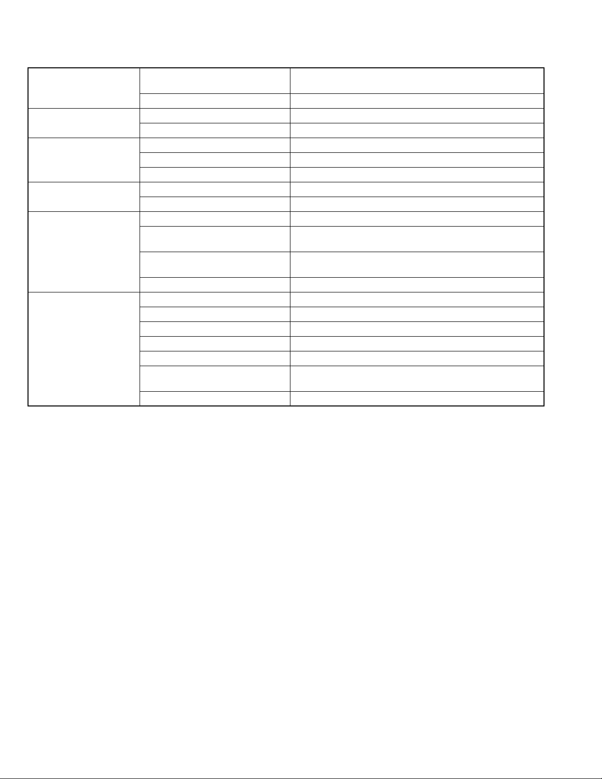
(5) Leakage shock hazard testing
After reassembling the product, always perform an isolation check on the exposed metal parts of the product (antenna terminals, knobs, metal cabinet, screw heads,
headphone jack, control shafts, etc.) to be sure the product
is safe to operate without danger of electrical shock.Do not
use a line isolation transformer during this check.
• Plug the AC line cord directly into the AC outlet. Using a
"Leakage Current Tester", measure the leakage current
from each exposed metal parts of the cabinet, particularly any exposed metal part having a return path to the
chassis, to a known good earth ground. Any leakage current must not exceed 0.5mA AC (r.m.s.).
• Alternate check method
Plug the AC line cord directly into the AC outlet. Use an
AC voltmeter having, 1,000Ω per volt or more sensitivity
in the following manner. Connect a 1,500Ω 10W resistor
paralleled by a 0.15µF AC-type capacitor between an ex-
posed metal part and a known good earth ground.
Measure the AC voltage across the resistor with the AC
voltmeter.
Move the resistor connection to each exposed metal
part, particularly any exposed metal part having a return
path to the chassis, and measure the AC voltage across
the resistor. Now, reverse the plug in the AC outlet and
repeat each measurement. Voltage measured any must
not exceed 0.75 V AC (r.m.s.). This corresponds to 0.5
mA AC (r.m.s.).
AC VOLTMETER
(Having 1000
ohms/volts,
or more sensitivity)
0.15 F AC TYPE
Place this
probe on
1500 10W
Good earth ground
1.2 Warning
(1) This equipment has been designed and manufactured to
meet international safety standards.
(2) It is the legal responsibility of the repairer to ensure that
these safety standards are maintained.
(3) Repairs must be made in accordance with the relevant
safety standards.
(4) It is essential that safety critical components are replaced
by approved parts.
(5) If mains voltage selector is provided, check setting for local
voltage.
1.3 Caution
Burrs formed during molding may be left over on some parts
of the chassis.
Therefore, pay attention to such burrs in the case of preforming repair of this system.
1.4 Critical parts for safety
In regard with component parts appearing on the silk-screen
printed side (parts side) of the PWB diagrams, the parts that are
printed over with black such as the resistor ( ), diode ( )
and ICP ( ) or identified by the " " mark nearby are critical
for safety. When replacing them, be sure to use the parts of the
same type and rating as specified by the manufacturer.
(This regulation dose not Except the J and C version)
each exposed
metal part.
(No.MB346)1-3
Page 4
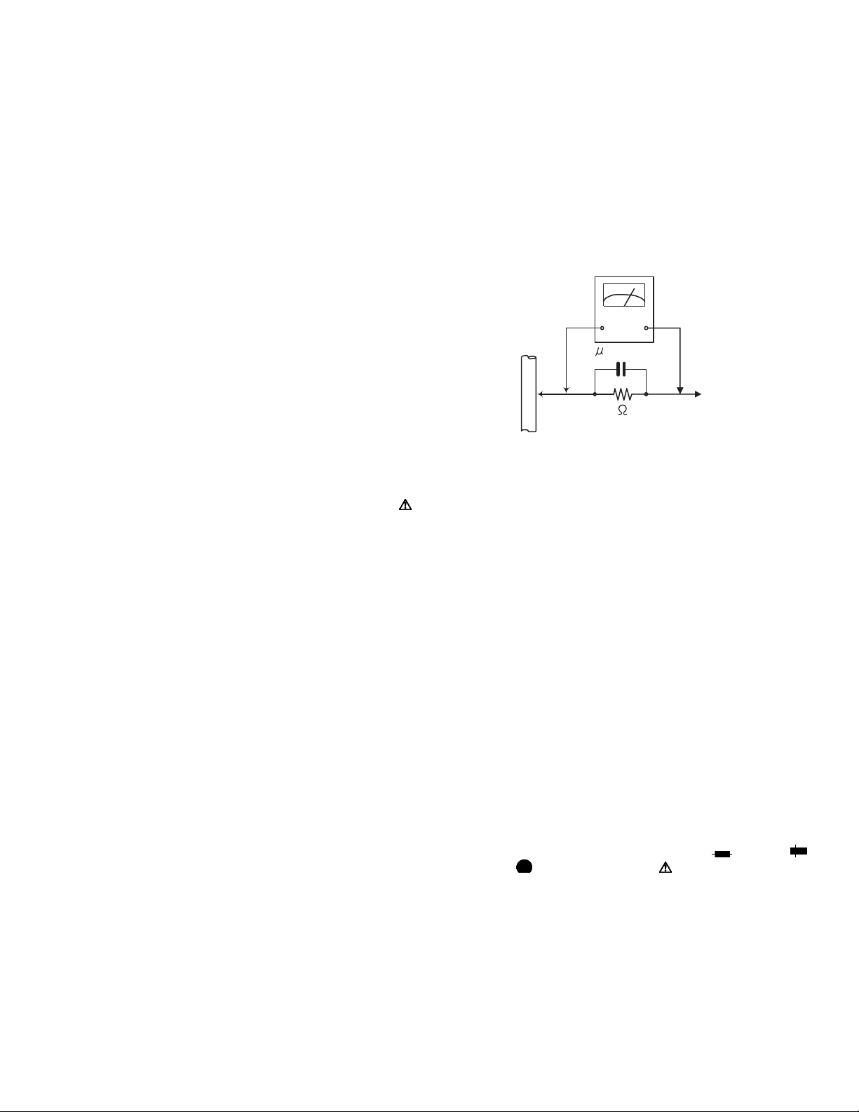
1.5 Preventing static electricity
Electrostatic discharge (ESD), which occurs when static electricity stored in the body, fabric, etc. is discharged, can destroy the laser
diode in the traverse unit (optical pickup). Take care to prevent this when performing repairs.
1.5.1 Grounding to prevent damage by static electricity
Static electricity in the work area can destroy the optical pickup (laser diode) in devices such as laser products.
Be careful to use proper grounding in the area where repairs are being performed.
(1) Ground the workbench
Ground the workbench by laying conductive material (such as a conductive sheet) or an iron plate over it before placing the
traverse unit (optical pickup) on it.
(2) Ground yourself
Use an anti-static wrist strap to release any static electricity built up in your body.
(caption)
Anti-static wrist strap
1M
Conductive material
(conductive sheet) or iron palate
(3) Handling the optical pickup
• In order to maintain quality during transport and before installation, both sides of the laser diode on the replacement optical
pickup are shorted. After replacement, return the shorted parts to their original condition.
(Refer to the text.)
• Do not use a tester to check the condition of the laser diode in the optical pickup. The tester's internal power source can easily
destroy the laser diode.
1.6 Handling the traverse unit (optical pickup)
(1) Do not subject the traverse unit (optical pickup) to strong shocks, as it is a sensitive, complex unit.
(2) Cut off the shorted part of the flexible cable using nippers, etc. after replacing the optical pickup. For specific details, refer to the
replacement procedure in the text. Remove the anti-static pin when replacing the traverse unit. Be careful not to take too long a
time when attaching it to the connector.
(3) Handle the flexible cable carefully as it may break when subjected to strong force.
(4) I t is not possible to adjust the semi-fixed resistor that adjusts the laser power. Do not turn it.
1.7 Attention when traverse unit is decomposed
*Please refer to "Disassembly method" in the text for the pickup unit.
• Apply solder to the short land sections before the flexible wire is disconnected from the connecto on the servo board. (If the flexible
wire is disconnected without applying solder, the pickup may be destroyed by static electricity.)
• In the assembly, be sure to remove solder from the short land sections after connecting the flexible wire.
CD changer
unit
1-4 (No.MB346)
Flexible cable
Soldering
Page 5
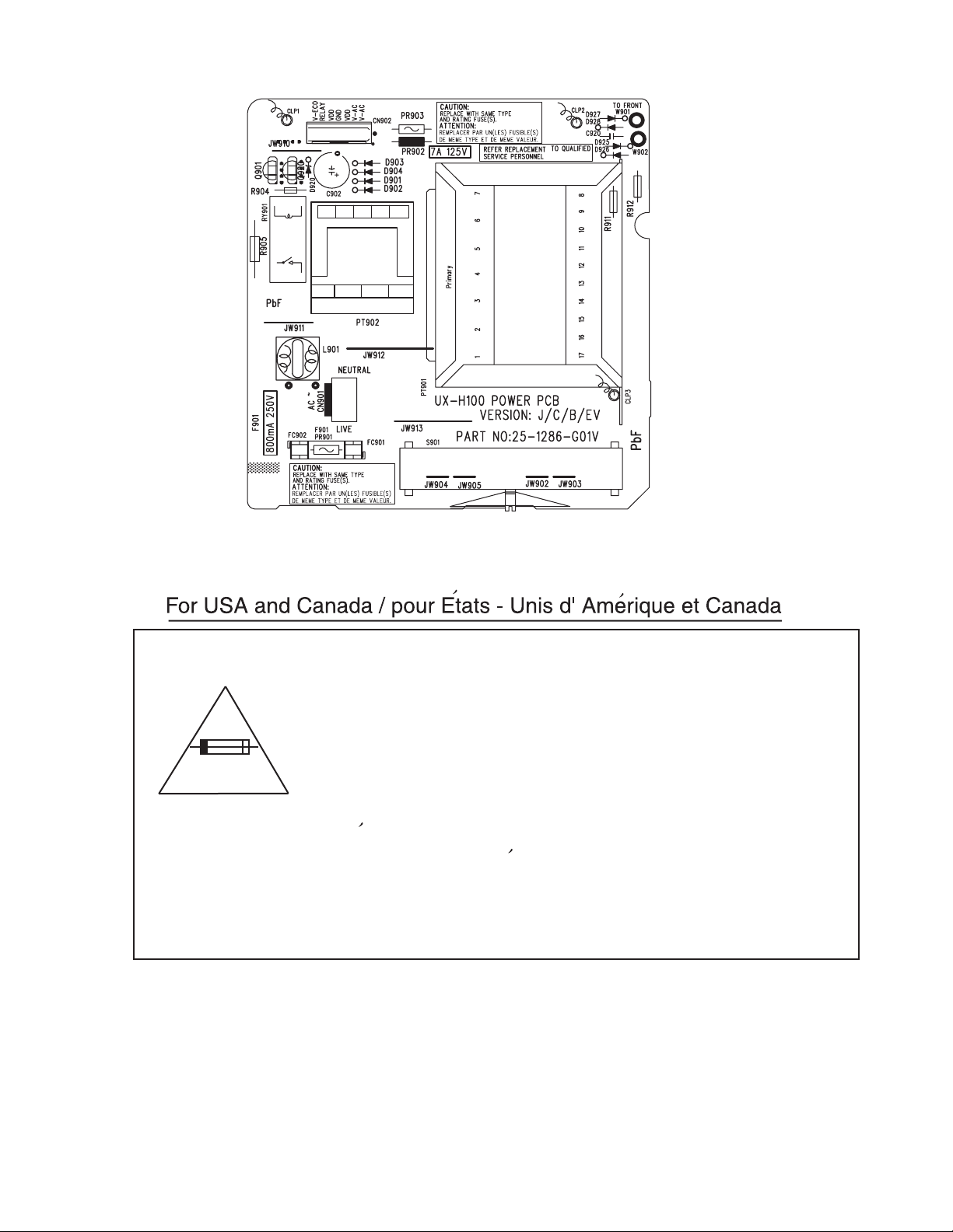
1.8 Importance administering point on the safety
Caution: For continued protection against risk of
fire, replace only with same type 800mA/125V for
F901. This symbol specifies type of fast operating
fuse.
Precaution: Pour eviter risques de feux, remplacez
le fusible de surete de F901 comme le meme type
que 800mA/125V.
Ce sont des fusibles suretes qui functionnes rapide.
^
(No.MB346)1-5
Page 6

SECTION 2
SPECIFIC SERVICE INSTRUCTIONS
This service manual does not describe SPECIFIC SERVICE INSTRUCTIONS.
1-6 (No.MB346)
Page 7
SECTION 3
r
DISASSEMBLY
3.1 Main body
3.1.1 Removing the rear cover
(See Fig.1 to 4)
(1) From the back of the body, remove the seven screws A at-
taching the rear cover.
(2) From both sides of the body, remove the eight screws B at-
taching the rear cover.
(3) Move the rear cover in the direction of the arrow and pull it
out from the main body.
Disconnect the antenna wire from antenna terminal on the
FM antenna board beside the rear cover.
Caution:
Before reattaching the rear cover, connect the antenna wire to
the antenna terminal on the antenna board.
Rear cover assembly
A
CD mechanism assembly
B
Front panel assembly
A
Front panel assembly
Fig.1
B
A
Rear cover
B
Fig.3
Rear cover
FM antenna board
Terminal
Antenna wire
B
Front panel assembly
Rear cover
Fig.4
Rear cove
Fig.2
(No.MB346)1-7
Page 8

3.1.2 Removing the FM antenna board
(See Fig.5)
• Prior to performing the following procedure, remove the rear
cover.
(1) Unsolder the three weld metal zone of the antenna board
on the rear cover.
(2) Remove the antenna board, which is weldered to the rear
cover at the three points a.
Rear cover
a
FM antenna board
Fig.5
a
1-8 (No.MB346)
Page 9

3.1.3 Removing the main board
(See Fig.6 to 8)
• Prior to performing the following procedure, remove the rear
cover.
(1) Disconnect the wire from connector CN202
and TP1 on the main board.
CN204
(2) Disconnect the wire from connector CN902
former board.
(3) Remove the two screws D on the left side of the body.
(4) Pull the main board out rearward with moving the CD
mechanism assembly in the direction of the arrow. Discon-
nect connector CN201
board in the front panel assembly section.
(5) Unsolder soldering b of the red wire connecting the main
board and the transformer board.
on the main board from the LCD
, CN203,
on the trans-
CD mechanism assembly
D
TP1
CN204
CN201
D
Main board
Front panel assembly
CN204
CN203
CD mechanism assembly
CN202
Fig.6
CD mechanism assembly
CN202
Fig.7
CN203
Front panel assembly
Main board
TP1
Transformer board
CN902
Front panel assembly
Transformer board
CN902
Fig.8
Main board
CN201
b
(No.MB346)1-9
Page 10

3.1.4 Removing the heat sink
(See Fig.9, 10)
• Prior to performing the following procedure, remove the rear
cover and the main board.
(1) Remove the two screws E, the two screws F and the two
screws G attaching the heat sink.
Heat sink
Main board
F
Heat sink
E
F
Fig.9
G
Main board
E
1-10 (No.MB346)
Fig.10
Page 11

3.1.5 Removing the CD mechanism assembly
(See Fig.11 to 14)
• Prior to performing the following procedure, remove the rear
cover and the main board.
(1) Disconnect the card wire from connector CN703
on the CD mechanism board.
CN704
(2) Push "OPEN" to open the CD door.
(3) Release the tab d on each side of the front panel assembly.
Push the CD mechanism assembly in the direction of the
arrow and remove rearward while releasing the two joint
tabs e on the top of the front panel assembly.
CD machanism assembly
and
CD mechanism assembly
Fig.13
d
Front panel assembly
CN703
Front panel assembly
CD mechanism board
CN704
Fig.11
CD mechanism assembly
d
e
d
Front panel assembly
CD door
CD mechanism assembly
Fig.14
CN703,CN704
Fig.12
(No.MB346)1-11
Page 12

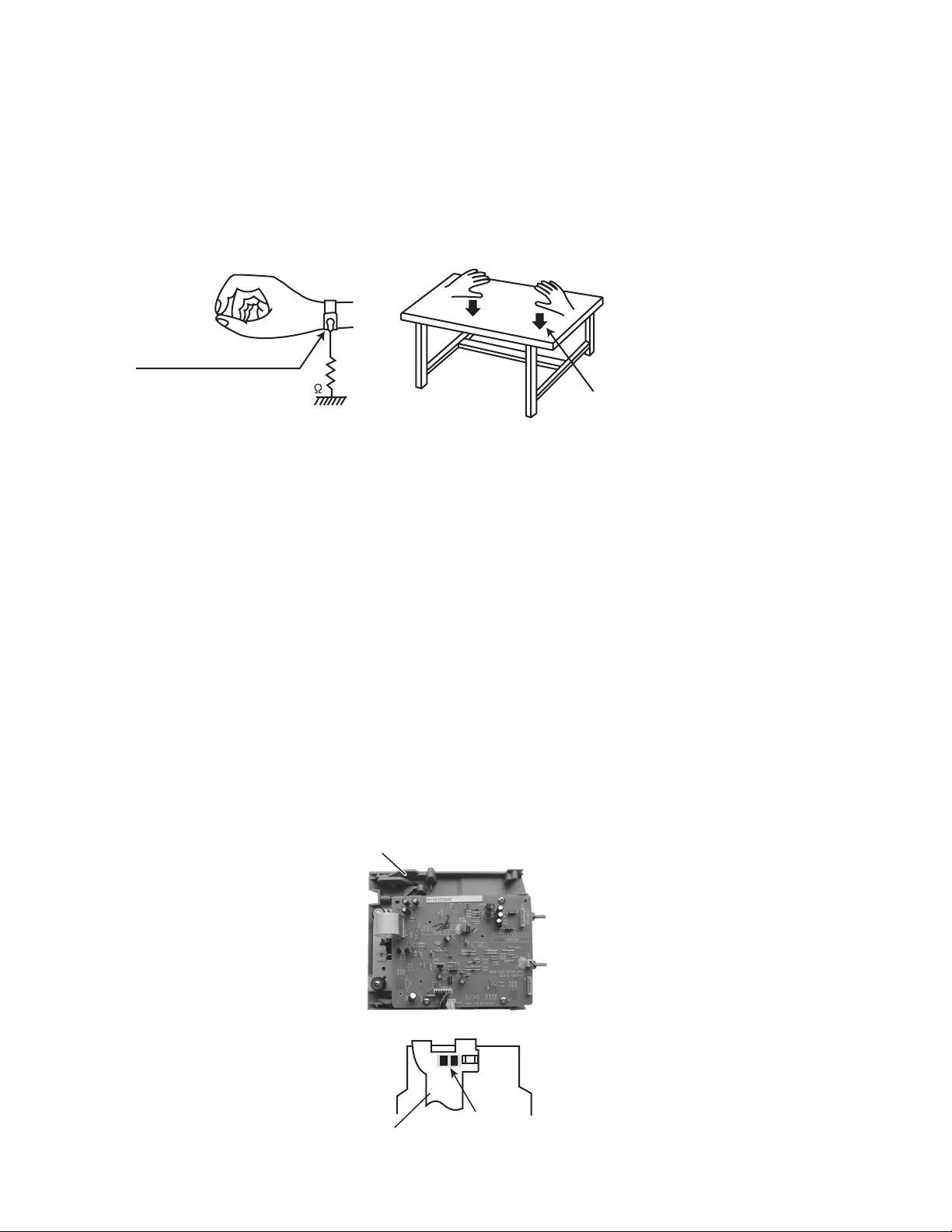
3.1.6 Removing the CD mechanism board
r
(See Fig.15 to 17)
• Prior to performing the following procedure, remove the rear
cover, the main board and the CD mechanism assembly.
Caution:
Before disconnecting the card wire from connector CN701
the CD mechanism board and the CD pickup board, make sure
to solder the short-circuit point on the CD pickup board. If you
do not follow this instruction, the pickup may be damaged.
(1) Disconnect the wire from connector CN705
mechanism board.
(2) Disconnect the wire from connector on the CD motor
board.
(3) Remove the three screws H attaching the CD mechanism
board.
(4) Move the CD mechanism board as shown in Fig.16 and
solder the short-circuit point on the CD pickup board.
(5) Disconnect the card wire from connector CN701
mechanism board.
Caution:
When reattaching the CD mechanism board, connect the card
wire to connector CN701
CD pickup board, then unsolder the short-circuit point.
on the CD mechanism board and the
on the CD
on
on the CD
H
CN705
CD mechanism assembly
Fig.15
CD motor board connecto
H
H
CD mechanism board
CN701
CD mechanism board
CN701
Card wire
Short-circuit point
CD motor board
CD mechanism assembly
CD pickup board
CD pickup board
Fig.16
Card wire
Solder
1-12 (No.MB346)
Short-circuit point
Fig.17
Page 13

3.1.7 Removing the CD mechanism
(See Fig.18)
• Prior to performing the following procedure, remove the rear
cover, the main board, the CD mechanism assembly and the
CD mechanism board.
(1) Remove the four screws J attaching the CD mechanism.
CD mechanism assembly
J
J
CD mechanism
Fig.18
J
J
(No.MB346)1-13
Page 14

3.1.8 Removing the front panel assembly
f
(See Fig.19 to 21)
• Prior to performing the following procedure, remove the rear
cover, the main board and the CD mechanism assembly.
(1) Disconnect the wire from connector W901 on the trans-
former board.
(2) From the bottom of the body, remove the two screws K at-
taching the front panel assembly.
(3) Release two joints f at the bottom of both sides and remove
the front panel assembly.
Front panel assembly
Transformer board
f
Transformer board
Wire
W901
Fig.19
Front panel assembly
1-14 (No.MB346)
Transformer board
Fig.20
Front panel assembly
Bottom
K
Fig.21
Page 15

3.1.9 Removing the LCD board
(See Fig.22, 23)
• Prior to performing the following procedure, remove the rear
cover, the main board, the CD mechanism assembly and the
front panel assembly.
(1) From the front panel, pull the volume knob out.
(2) Remove the nine screws M attaching the LCD board.
Fronto panel assembly
Volume knob
Front panel assembly
M
M
Fig.22
LCD board
M
Fig.23
(No.MB346)1-15
Page 16

3.1.10 Removing the cassette mechanism assembly
(See Fig.24, 25)
• Prior to performing the following procedure, remove the rear
cover, the main board, the CD mechanism assembly and the
front panel assembly.
(1) Push the eject button of the cassette door on the front pan-
el.
(2) Remove the four screws N attaching the cassette mecha-
nism assembly.
Cassette door
Eject button
Cassette mechanism assembly
N
N
Front panel assembly
Front panel assembly
Fig.24
N
N
Fig.25
1-16 (No.MB346)
Page 17

3.1.11 Removing the power transformer assembly
(See Fig.26)
• Prior to performing the following procedure, remove the rear
cover and the main board.
(1) Disconnect the power cord from connector CN901
transformer board.
(2) Disconnect the wire from connector W901
former board.
(3) Remove the four screws P attaching the power transformer
assembly.
Caution:
In case of disconnecting the power cord from the main body,
get it through the notch of the base cabinet as shown in Fig.26
and fix it.
on the
on the trans-
Transfomer board
CN901
Power cord
Transformer board
W901
Wire
P
3.1.12 Removing the cassette deck main motor, and replacing the main belt
(See Fig.27 & 28)
• Prior to performing the following procedures, remove the rear
cover.
• Also remove the CD chassis assembly.
• Also remove the bottom base assembly.
(1) Remove the four screws J retaining the cassette deck
mechanism.
(2) Remove the cassette deck mechanism.
(3) Remove the two screws L retaining the main motor from
the back side of the cassette deck and the top side of the
cassette deck.
Caution:
After attaching the main motor, check the orientation of
the motor and the polarity of the wires.
(4) Form the backside of the cassette deck, remove the main
motor and the main belt.
P
Power transformer assembly
Fig.26
L
Fig.27
Fig.28
L
(No.MB346)1-17
Page 18

3.1.13 Removing the cassette deck head
(See Fig.29)
• Prior to performing the following procedures, remove the rear
cover.
• Also remove the CD chassis assembly.
• Also remove the bottom base assembly.
(1) Remove the four screws J that retain the cassette deck
mechanism.
(2) Remove the cassette deck mechanism and place it so that
the front side faces up.
(3) Remove the solder from the bottom side of the head termi-
nal and disconnect the wire.
(4) Remove the screw M that retains the head.
(5) Remove the screw N that retains the head.
(6) Hold the head and slide it in the direction of the arrow to re-
move it.
N
Fig.29
M
1-18 (No.MB346)
Page 19

SECTION 4
ADJUSTMENT
4.1 Measurement instruments
(1) Low frequensy oscillator
(2) Attenuator (Impedance : 600 Ω)
(3) Electronic voltmeter
(4) Frequency counter
(5) Wow flutter meter
(6) Test tape
VT712 : for tape speed and wow flutter (3kHz)
VT703 : for head angle (10kHz)
(7) Blank tape
TAPE l : AC-225
TAPE ll : AC-514
(8) Torque gauge
TW2111A : for play and back tension forward
TW2121A : for play and back tension reverce
TW2231A : for FF and rewind
(9) Test disc : CTS-1000 (12cm), GRG-1211 (8cm)
(10) Jitter meter
4.2 Measurement conditions
(1) Power supply voltage : AC 120V (60Hz)
(2) Output terminal : Speaker out
: TP101 (for TUNER/DECK/CD)
: Dummy load 6
4.3 Standard measurement position
(1) Power : Standby (Light STANDBY Indicator)
(2) Bass / Treble : 0
(3) Sound mode : OFF
(4) Main VOL. : 0 Minimum
4.4 Precautions for measurement
(1) Apply 30pF and 33k ohm to the IF sweeper output side and
0.082µF and 100k ohm in series to the sweeper input side.
(2) The IF sweeper output level should be made as low as pos-
sible within the adjustable range.
(3) Since the IF sweeper is a fixed device, there is no need to
adjust this sweeper.
(4) Since a ceramic oscillator is used, there is no need to per-
form any MPX adjustment.
(5) Since a fixed coil is used, there is no need to adjust the FM
tracking.
(6) The input and output earth systems are separated.
In case of simultaneously measuring the voltage in both of
the input and output systems with an electronic voltmeter
for two channels, therefore, the earth should be connected
particularly.
(7) In the case of BTL connection amplifier, the minus terminal
of speaker is not for earthing. Therefore, be sure not to connect any other earth terminal to this terminal.
(No.MB346)1-19
Page 20

4.5 Arrangement of adjusting positions
4.6 Tape recorder section
Items Measurement method
Cassette head
azimuth alignments
Recording Bias
frequency alignment
Test tape
: VT703 (10kHz)
Measurement output
terminal
: Left and Right
speaker output
(6 ohm loaded)
or Headphone output
(32 ohm loaded)
Test tape
: TYPE I AC-514
Measurement output
terminal
: Erase head terminal
(CN202 2th pin)
Measurement
conditions
Cassette deck mechanism
(Front side)
REC/PB Head
(Deck-B)
Head azimuth screw
(Forward side)
Head azimuth screw
(Reverse side)
1. Playback the test tape VT703 or equivalent.
2. Adjust the head azimuth screw to obtain maxmum
output and both output of L/R is in 3 dB.
3. Put on the screw lock paint after alignments.
1. Insert the recording tape in deck-B.
2. Starting the recording.
3. Adjust the oscillation frequency to 82kHz +/- 3kHz
by core of oscillation coil of T201.
Standard
values
Maximum
output
82kHz +/- 3kHz
Adjusting
positions
Adjust the head
azimuth screw
only when the head
has been changed.
Use the highimpedance probe
or frequency counter
input.
4.7 Tuner section
Items Measurement method
AM tracking
alignments
AM IFT alignments
Measurement
conditions
Input signal
: 1710kHz / 600kHz
Adjustment point
: Antenna coil (T2)
Input signal
: 530kHz
Adjustment point
: IFT (T1)
1. Set the signal generator signal to 1710kHz the
feed to loop anenna.
2. Receiving the signal and the adjust the coil (T2)
obtain the V.T. is 7.3V +/- 0.05V.
3. Change the receiving frequency to 600kHz
(603kHz).
4. Adjust the antenna coil (T2) obtain maximum
sensitivity. (Adjust the SSG output ot out of AGC
range.
1.Set the receiveing frequency to 530kHz.
2. Feed the 450kHz signal to AM antenna input.
3. Adjust the IFT block T1 obtain to maximum output.
(Adjust the SSG output to out of AGC range.)
Standard
values
V.T.
: 7.3V +/- 0.05V
Maximum
sensitivity
Maximum
output
Adjusting
positions
Adjust the OSC coil
only when the AM
coil block has been
changed.
Adjust the IFT only
when the IF block
has been changed.
1-20 (No.MB346)
Page 21

SECTION 5
TROUBLESHOOTING
This service manual does not describe TROUBLESHOOTING.
(No.MB346)1-21
Page 22

Victor Company of Japan, Limited
AV & MULTIMEDIA COMPANY AUDIO/VIDEO SYSTEMS CATEGORY 10-1,1chome,Ohwatari-machi,Maebashi-city,371-8543,Japan
(No.MB346)
Printed in Japan
VPT
 Loading...