

Page 1

SF-L100FG
EF-S100FG
PK-F100BG
(Fixed Polarized Screen)
(Ecran polarisé fixe)
(Screen Stand)
(Pied d’écran)
(Support bar)
(Barre de support)
100" Fixed Polarized Screen and Stand
Ecran polarisé fixe de 100” et pied
Instruction Manual
Mode d’emploi
BHU-30001-014
• Thank you for buying the 100”Fixed Polarized Screen
• SF-L100FG, EF-S100FG and PK-F100BG are sold
separately and are not included.
• Before installing and operating the unit, read this
instruction manual carefully for proper operation, and
retain this manual for your future reference along.
• A serial number is important for product quality control.
When you buy the unit, check if the serial number is
properly marked on the rear of the unit.
• Merci pour avoir acheté l’Ecran polarisé fixe de 100”
• Les SF-L100FG, EF-S100FG et PK-F100BG sont venus
séparément et ne sont pas fournis.
• Avant d’installer et d’utiliser l’appareil, lire attentivement
ce mode d’emploi pour s’assurer d’une utilisation correcte
et le conserver à titre d’information future.
• Le numéro de série est important pour le contrôle de la
qualité du produit. Lors de l’achat du produit, vérifier si le
numéro de série est correctement marqué au dos du
produit.
Page 2

PRECAUTIONS FOR SAFE AND PROPER USE
Numerous symbols are employed as indication in the precautions for safety, precautions for handling, and in the indication to
the products. These are designed to prevent in advance any possible infliction of injury on you and other individuals and the
damage of properties through the proper use of the product. The symbols and meanings are shown below. Grasp the contents
of the symbols completely before reading this manual.
This symbol informs you of the presence of the contents that demands caution (including danger and warning).
Specifically prohibited contents (caution against electric shock in case of the left symbol) are illustrated in the
symbol.
This symbol informs you of prohibited actions. Specifically prohibited contents (prohibition of disassembly
in case of the left symbol) are illustrated in the symbol and its vicinity.
This symbol informs you of the contents that forces you to take some action or gives you some guidelines or
instructions. Specific contents of instructions (unplug the power cord from the outlet in case of the left symbol)
are illustrated.
Regarding Symbol Indications
Examples of Symbol Indications
WARNING
CAUTION
This represents the contents in which the probabilities for death or serious
injury are assumed if this symbol indication is ignored and the product is
erroneously handled.
This represents the contents in which the probabilities for injury to be inflicted
are assumed and the contents in which material damages to be sustained are
assumed if this symbol indication is ignored and the product is erroneously
handled.
– 2 –
English
Page 3

– 3 –
WARNING
Never modify the screen. Otherwise, the damage
of the unit and injury can result.
Install all bolts and nuts on the product properly.
Otherwise, the damage of the unit and injury can
result.
Do not install the product on a tilted or unstable
surface or in places where it is subject to vibration
or shock. Drop or fall can result in injury.
Do not ride on the product. Motion and fall can
result in injury.
The screen itself weighs 20kg (mass) and has a
size of 2.082m x 1.574m; therefore, it is
recommended that two persons perform the
Fixed Polarized Screen and Screen Stand
Fixed Polarized Screen
Do not hang on or hock anything on the screen.
Drop or fall can result in injury.
If the wall on which the product is installed has an
insufficient strength, or if it is not installed
correctly, it may fall and cause injury or failure.
The wall must support a mass of 200k
g.Contact
your dealer before installation.
Screen Stand
Fixed Polarized Screen and Screen Stand
Fixed Polarized Screen
Do not install the unit in a place where it is
exposed to direct sunlight, high heat or humidity,
or dust accumulates.
Do not touch the screen surface or write letters
or draw pictures on the screen. Ink and paints
on the screen cannot be wiped off.
Wipe off dust from the screen surface using a
dry cloth or a soft brush. Do not use benzine or
thinner. Otherwise, the screen may be
damaged.
If the screen is tarred or oiled, wipe it off with a
soft cloth moistened with a neutral detergent.
Screen Stand
Do not place heavy objects, or articles other
than the determined objects, on top of the
screen because this may disturb the balance
and cause the screen to fall and become
damaged.
After installation, secure the double-wheel
caster stoppers. Otherwise, the damage of the
unit and injury can result.
Do not attempt to move the screen with the twowheel casters locked because this may result in
damage to the floor, the casters or the screen.
Firmly insert the height adjustment stopper
handle into the hole in the slide pipe and make
sure the slide pipe is locked before using;
otherwise, tilting of the screen, injury or damage
to the screen may result.
Adjust the heights of the left and right side slide
pipes so that screen height is the same on the
left and right sides to prevent stressing the
screen. Stress can result in damage to the
equipment.
CAUTION
CAUTION
English
Page 4

– 4 –
English
Accessories
115
70
115
70
15
1143
M6×10
M5×10
M5
10
SF-L100FG(Fixed Polarized Screen)
EF-S100FG(Screen Stand)
PK-F100BG(Support bar)
S-q Screen (One)
E-
u M6 Hexagon nuts (2)
E-
!0 Angle fixing
knobs (2)
E-
i Double-wheel
casters with stoppers (2)
P-
q Horizontal screen stay (One)
P-
w Angle adjusting
plate (L) (One)
P-
e Angle adjusting
plate (R) (One)
P-
r Hexagon head bolts
with washers M6
×10 (4)
P-
t Hexagon head bolts
M5
×10 (4)
P-
y Hexagon nuts
(M5) (4)
E-
!1 Nylon
washers (2)
E-
o Double-wheel casters
without stoppers (2)
E-
!2 Spanners
(M5e•M6) (2))
E-
!3 Spanners for caster
(M8) (One)
Instruction Manual
(this manual) (One)
E-
y Hexagon head
bolts with washers
M6
×50 (2)
E-
t Hexagon
head bolts with
washers M6
×40 (2)
E-
r Joint pipe (B) (One)
E-
e Joint pipe
(A) (One)
E-
w Stand base
(L) (One)
E-
q Stand base
(R) (One)
S-
w Wall fittings(4)
S-
e Concrete
anchors (16)
S-
r Hexagon head
bolts (M6) (16)
S-
t Wood
screws (16)
Instruction Manual
(this manual) (One)
Page 5

1282 / 50.5(Recomended value)
– 5 –
English
The screen can be either stand-mounted or wall-mounted.
Stand-mounted installation
SF-L100FG(Fixed Polarized Screen), EF-S100FG(Screen Stand), PK-F100BG(Support bar) are necessary.
(Unit : mm / inch)
Wall-mounted installation
SF-L100FG(Fixed Polarized Screen) is necessary.
(Unit : mm / inch)
Installation
Min.1937(~Max.2437)
/Min.76.3(~Max.96)
Min.1150(~Max.1650)
/Min.45.3(~Max.65)
1674 / 62
Approx. 1668 / 65.7
2082 / 82
2082 / 82
2032 / 80
10° 10°
1524 / 60
1574 / 62
26
/ 1.02
Page 6

– 6 –
The screen itself weighs 20kg and has a width of 2m; therefore, it is recommended that transport, packing and
installation, etc., be performed by two persons to prevent damage to the screen.
Stand-mounted installation
SF-L100FG(Fixed Polarized Screen), EF-S100FG(Screen Stand) and PK-F100BG(Support bar) are necessary.
10-8
10-8
10-8
• Install P-wAngle adjusting plate(L) and P-eAngle adjusting plate (R) on the back of the S-qScreen
• Turn over S-
qScreen with the logo mark facing downward. Install P-wAngle adjusting plate(L) on the left
plate and install P-
eAngle adjusting plate (R) on the right plate attached to the screen and V frame using E-!2
Spanner.
Do not damage the screen surface.(Place a soft cloth or air cap on a flat surface and put the
screen on it.)
• Install the P-qHorizontal screen stay on the back of the screen, insert P-tHexagon head bolts into the
holes in P-
w and P-e Angle adjusting plates from outwards and temporarily fix them with P-yHexagon
nuts.
• Tighten P-
t Bolts and P-y Nuts with two spanners. Assembling the screen is now complete.
(1) Install Angle adjusting plate
(2) Install P-q
Horizontal screen stay
P-e
E-!2
E-!2
P-q
P-t
P-r
P-w
E-y Hex nut
For M6
For M6
English
E-!2 Spanner
For M6
Page 7

– 7 –
English
1
8−0
• Tilt the stand as shown above and insert E-i, E-o Double-wheel caster into the
holes in the bottom of the stand bases (R) and (L), and tighten them with E-
!3
Spanner for casters.
There are two casters with stoppers and two casters without stoppers.
Install them at the locations shown in the figure above.
Move : raise the lever.
Fix: Push the lever down.
• Place the E-q and E-w Stand base as shown above and install E-e Joint
pipe (A).
• Install right and left E-
t Hexagon head bolts with washers temporarily.
• Place the E-
q and E-w Stand base as shown above and install E-r Joint
pipe (B).
• Install right and left E-
y Hexagon head bolts with washers and E-u
Hexagon nuts temporarily.
• Tighten the bolts and nuts with E-
!2Spanners.
(3) Install E-e Joint pipe (A) and E-r Joint pipe (B) on E-q Stand base (R) and
E-
w Stand base (L)
(4) Install E-i, E-o Double-wheel caster
E-w
E-y
E-e
E-q
E-
t
E-r
E-!2
E-u
E-i,
E-
o
E-!3
Up: Move
Down:
Fix
Page 8

– 8 –
English
(2) Angle adjusting plate
Slide pipe
(9) Stand base (L)
(7) Screen
Stopper handle
Slide pipe
•
When the stopper handle is pulled in the direction of the arrow, the slide pipe moves up or down. Align the
hole in the slide pipe with the stopper handle position, return the stopper handle, and fix the slide pipe. The
heights of the right and left slide pipes must be the same.
•
Fit the catch of the slide pipe to the notch of the Angle adjusting plate installed on the back of the screen.
• Install the right and left slide pipes at the same time.
• Lock the caster stoppers.
The screen itself is heavy, mass 20k
g, so it is recommended that the work be performed by two persons.
The height of the slide pipe can be adjusted
by up to 500 mm at 50mm intervals.
(5) Ajust the height
(6) Install S-
q Screen
S-q
Page 9
– 9 –
English
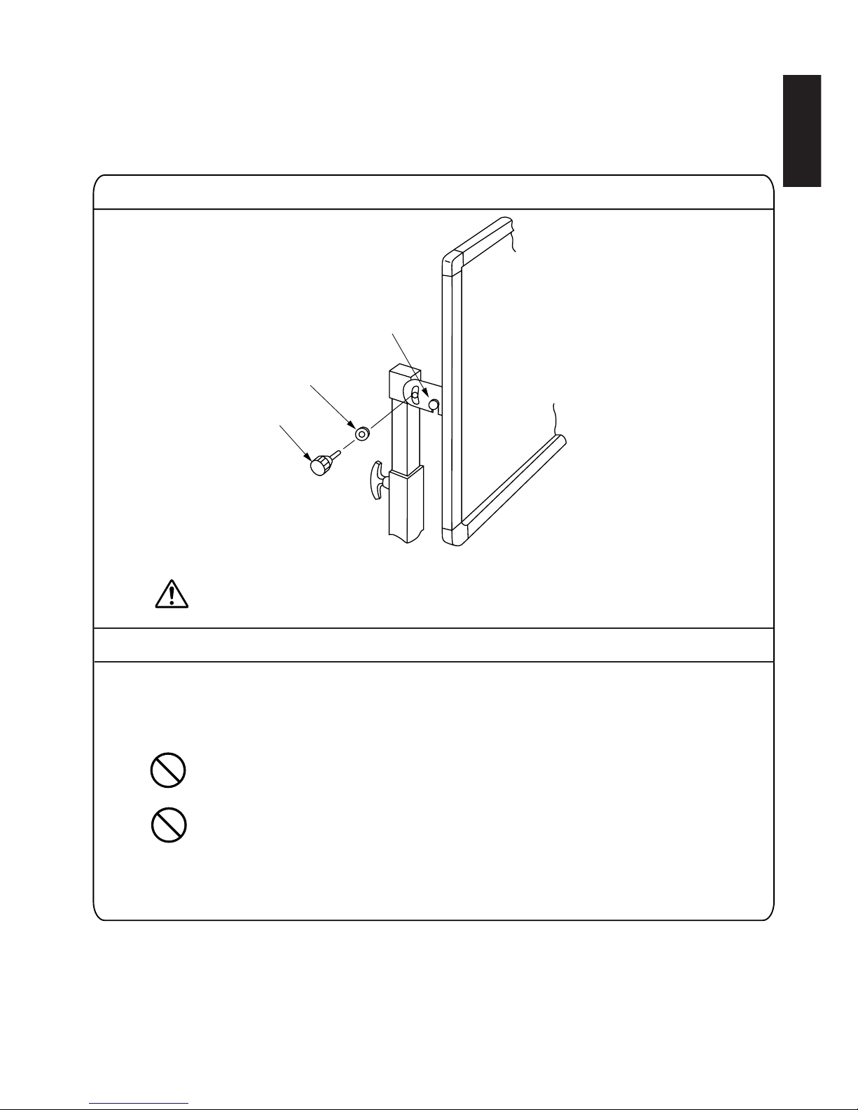
•
Install E-!1 Nylon washer on E-!0 Angle fixing knob and secure Angle adjusting plate.
Adjust the screen angle at this time.
•
If the height is adjusted with the screen installed, adjust the height of each slide pipe by one pitch (50 mm)
at a time.
When the stopper is removed, the slide pipe will drop due to the weight of the screen;
therefore, when removing the slide pipe, always support the screen to prevent dropping,
injury or damage to the screen.
If the height is changed by more than two pitch at a time, the screen may be distorted and
damaged.
E-!1
E-!0
(7) Secure the knob
(8) Height ajustment
Page 10

– 10 –
English
Wall-mounted installation
SF-L100FG (Fixed Polarizing Screen) is necessary.
In some cases, use of the wall-mount fixtures requires specialized knowledge; therefore, it is recommended that the installation work be
entrusted to a professional.
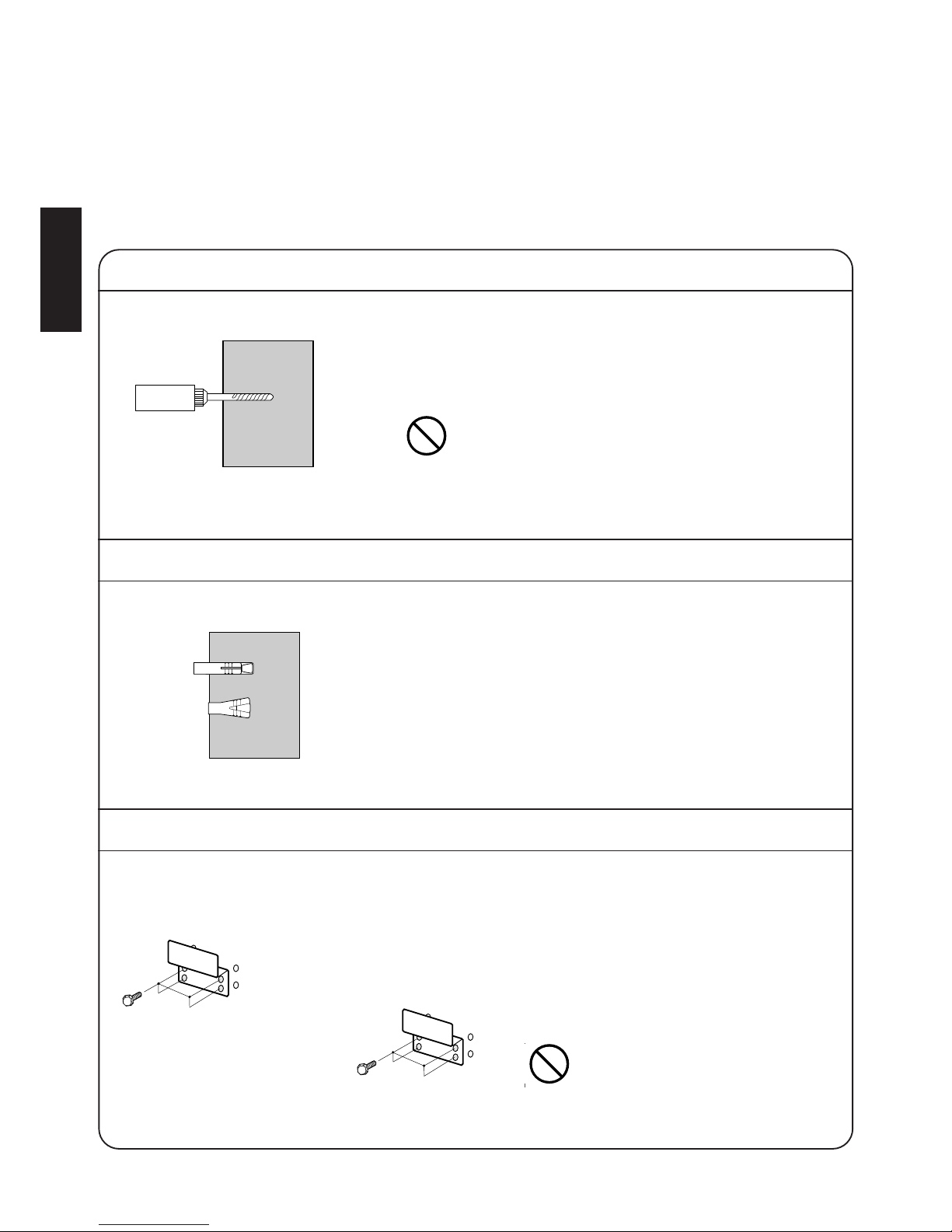
Installing the screen on a concrete wall.
(2) Install the concrete anchor
(1) Drill a hole
Be careful not to penetrate the wall when driving the
concrete anchors. A wall thickness of 40mm or more is
recommended
Drill a hole (diameter : 11mm depth : 30 mm) in a wall.
•
Insert the S-eM6 concrete anchor into the hole and use a driving
rod to drive it in until flush with the wall surface. The driving rod is
not included and must be purchased separately.
(3) Attaching the wall-mount fixtures at the bottom of the screen
Fasten the S-w wall-mount fixtures w at the bottom of
the screen with eight S-
r M6 hex head bolts.
Mount the S-
q screen on the S-w wall-mount fixtures.
The screen itself is heavy, mass 20kg, so
it is recommended that the work be
performed by two persons.
Page 11

– 11 –
English
(4) Install the screen
Fasten the two S-w wall-mount fixtures with eight S-r M6 hex head bolts.
Installing the screen on a plywood wall
Fasten the two S-w wall-mount fixtures to the
wall with S-
t wood screws. A composite board
thickness of at least 55mm is required.
(1) Attaching the wall-mount fixtures at the bottom of the screen
(2) Mounting the screen
Mount the S-q screen on the S-w wall-mount fixtures.
Fasten the two S-
w wall-mount fixtures to the wall with S-t wood screws.
The screen itself is heavy, mass 20kg, so it is recommended that the work be performed by two
persons.
➪
➪
Page 12
– 12 –
English
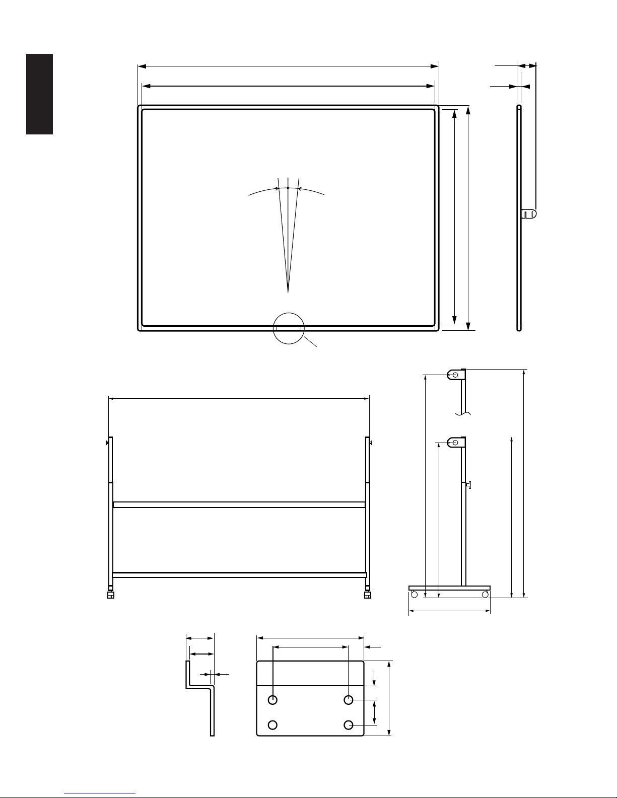
Vertical optical axis:
vertical ±5˚or less
Logo mark
2082 / 82
2032 / 80
1948 / 76.7
26
/ 1.02
3 / 0.12
(Unit : mm / inch)
23
/ 0.90
100 / 3.94
23 14
/ 0.90 0.55
70 / 2.76
70 / 2.76
15
/ 0.59
139
/ 5.47
22
/ 0.87
5° 5°
1524 / 60
1574 / 62
Max.1650 / 65
Min. 1150 / 45.3
Min.1191 / 46.9
Max.1691 / 66.6
Page 13

– 13 –
English
Specifications
Product name: 100 Fixed Polarized screen
Model : SF-L100FJ
Type : Polarizing screen, frame type
Screen Size : 2032mm (width)
× 1524mm (height)
Vertical optical axis : vertical ±5 degrees or less
Screen gain : 3.0 (Average)
View angle :
α(1/2) : Horizontal 25 degrees, Vertical 12 degrees
β(1/3) : Horizontal 32 degrees, Vertical 16 degrees
Mass : 20.5k
g
Packing total mass : 37kg
Operating temperature and humidity : -10 to 50˚C (15% to 80%)(No condensing)
Storage temperature and humidity : -20 to 60˚C (10% to 95%)(No condensing)
Product name: Screen Stand
Model : EF-S100FJ
Mass : 15.7k
g
Packing total mass : 26.7kg
Operating temperature and humidity : -10 to 50˚C (15% to 80%)(No condensing)
Storage temperature and humidity : -20 to 60˚C (10% to 95%)(No condensing)
Product name: Support bar
Model : PK-F100BG
Mass : 1.2 k
g
Packing total mass : 2.0 kg
Operating temperature and humidity : -10 to 50˚C (15% to 80%)(No condensing)
Storage temperature and humidity : -20 to 60˚C (10% to 95%)(No condensing)
VICTOR COMPANY OF JAPAN, LIMITED
VICTOR COMPANY OF JAPAN, LIMITED
The specifications are subject to change without prior notice.
Notes concerning this manual:
(1) Transfer of the contents in this manual to other literature without our prior approval is strictly prohibited.
(2) The contents of this manual, the specifications and external appearance of this unit are subject to change with-out notice.
(3) Illustrations used in this manual may slightly differ from the actual configuration of this unit.
Page 14

– 14 –
Français
PRECAUTIONS DE SECURITE POUR UNE
UTILISATION CORRECTE DE L’APPAREIL
De nombreux symboles sont utilisés comme indication dans les précautions de sécurité, les précautions relatives au transport
et dans les indications du produit. Ils sont conçus pour prévenir tout risque de blessure personnelle ou d’autrui et d’empêcher
tout dommage matériel à travers l’utilisation correcte de l’appareil. Les symboles et leur signification sont indiqués ci-dessous.
Bien comprendre la signification de ces symboles avant de lire ce mode d’emploi.
Ce symbole informe de la présence d’informations qui demandent des précautions particulières (incluant danger
et avertissement). Plus spécialement, des informations d’interdiction (précautions contre les chocs électriques
dans le cas du symbole de gauche) sont représentées par ce symbole.
Ce symbole informe sur des actions interdites. Plus spécialement, des informations d’interdiction (interdiction de
démonter l’appareil dans le cas du symbole de gauche) sont représentées par ce symbole et son voisinage.
Ce symbole informe de la présence d’informations qui obligent à prendre certaines mesures ou donne certaines
directives ou instructions. Le contenu spécifique des instructions (débrancher le cordon d’alimentation de la
prise murale dans le cas du symbole de gauche) est illustré.
A propos des symboles
Exemples de symboles et d’avertissements
AVERTISSEMENT
ATTENTION
Ce symbole informe de risques de mort ou blessures graves
si les avertissements contenus sous ce symbole sont ignorés
et que le produit est manipulé d’une façon erronée.
Ce symbole informe de risques de blessures et de
dommages matériels si les avertissements contenus sous ce
symbole sont ignorés et que le produit est manipulé d’une
façon erronée.
Page 15

– 15 –
Français
AVERTISSEMENT
Ne pas modifier l’ecran. Sinon, l’appareil risque
d’être endommagé et il y a des risques de
Installer correctement tous les boulons et écrous
sur le produit. Sinon, l’appareil risque d’être
endommagé et il y a des risques de blessures.
Ne pas installer le produit sur une surface inclinée
ou instable, ou dans un emplacement où il peut
être soumis aux vibrations ou chocs. La chute de
l’appareil peut provoquer des blessures.
Ne pas marcher sur le produit. Un mouvement et
une chute peuvent provoquer des blessures.
L’écran pèse 20 kg et a une taille de 2,082m x
1,574m; Par conséquent, il est recommandé que
deux personnes réalisent le montage.
Ecran polarisé fixe et pied d’écran
Ecran polarisé fixe
Ne pas suspendre ou accrocher un objet
quelconque sur l’écran. La chute de l’appareil
peut provoquer des blessures.
Si le mur ou le plafond, auquel est monté le
produit, n’est pas suffisamment résistant, ou s’il
n’est pas installé correctement, il pourra tomber
ou causer un endommagement ou une blessure.
Le mur ou le plafond peut supporter une masse
de 200k
g. Dans ce cas contacter le fournisseur
avant d’installer.
Pied d’écran
Ecran polarisé fixe et pied d’écran
Ecran polarisé fixe
Ne pas installer l’unité dans un emplacement où
elle seraexposée aux rayons directs du soleil, à
une haute chaleur ou humidité, ou à la poussiére.
Ne pas toucher à la surface de l’écran ou écrire
des lettres et faire des dessins sur l’écran.
L’encre ou les peintures sur l’écran ne peuvent
pas étre nettoyées.
Eliminer la poussière de la surface de l’écran
avec un chiffon sec ou une brosse souple. Ne
pas utiliser de diluant ou de benzine, car on
risque d’endommager l’écran.
Si l’écran est goudronné ou souillé par de l’huile,
le nettoyer avec un chiffon souple imbibé de
détergent neutre.
Pied d’écran
Ne placer aucun objet lourd ou autre objet en
dehors des objets spécifiés sur l’écran car cela
pourrait modifier son équilibre, le faire tomber et
l’endommager.
Aprés l’installation, fixer les pièces de retenue
des roulettes à doubles roues.
Ne pas essayer de déplacer l’écran avec les
roulettes à deux roues verrouillées car cela
pourrait endommager le sol, les roulettes ou
l’écran.
Insérer fermement les tiges de butée
d’ajustement de la hauteur dans le trou du tube
coulissant et s’assurer que le tube coulissant est
verrouillé avant d’utiliser l’écran; sinon, cela
pourrait entraîner une inclinaison de l’écran, des
blessures ou un endommagement de l’écran.
Ajuster les hauteurs des tubes coulissants
latéraux gauche et droit de façon que la hauteur
de l’écran soit la même du côté gauche et droit
pour éviter une compression de l’écran. Une
compression de l’écran peut endommager
l’équipement.
ATTENTION
ATTENTION
Page 16

– 16 –
Français
Accessories
115
70
115
70
15
1143
M6×10
M5×10
M5
10
SF-L100FG(Ecran polarisé fixe de 100”)
EF-S100FG (Pied d’écran)
PK-F100BG (Barre de support)
S-q Ecran (une pièce)
E-
u Ecrous hexagonaux (M6) (2)
E-!0 Boutons de
fixation d’angle (2)
E-
i Roulette à roues
doubles (avec retenue)
(2)
P-
q Support horizontal de l’écran
(une pièce)
P-
w Plateau de règlage
d’angle (D) (une pièce)
P-e
Plateau de
règlage d’angle (G)
(une pièce)
P-
r Boulons à tête
hexagonale avec
rondelles M6
×10 (4)
P-t Boulons à tête
hexagonale M5×
10 (4)
P-
y Ecrous
hexagonaux (M5) (4)
E-!1 Rondelles
de nylon (2)
E-
o Roulette à roues
doubles (sans retenue) (2)
E-!2 Clefs anglaises
(M5e•M6) (2)
E-!3 Clefs anglaises pour
roulette (M8) (une pièce)
Mode d’emploi
(ce mode d’emploi)
(une pièce)
E-
y Boulons à tête
hexagonale avec
rondelles M6×50 (2)
E-t Boulons à tête
hexagonale avec
rondelles M6
×40 (2)
E-r Tuyau de joint (B)
(une pièce)
E-e Tuyau de joint
(A) (une pièce)
E-
w Base de
support (G)
(une pièce)
E-q Base de
support (D)
(une pièce)
S-
w Accessoires de paroi (4)
S-e Ancrages de
béton (16)
S-r
Boulons à tête
hexagonale (M6) (16)
S-
t Vis du
bois (16)
Mode d’emploi (ce mode
d’emploi) (une pièce)
Page 17

– 17 –
Français
1282(Valeur recommandée)
/ 50.5
L’écran peut être soit monté sur le mur ou monté sur pied.
Installation de montage sur pied
SF-L100FG (Ecran polarisé fixe de 100”), EF-S100FG (Pied d’écran) et PK-F100BG (barre de support) sont nécessaires.
(Unité : mm / pouce)
Installation de montage au mur
SF-L100FG (Ecran polarisé fixe de 100”) est nécessaire.
(Unité : mm / pouce)
Installation
Min.1937(~Max.2437)
/Min.76.3(~Max.96)
Min.1150(~Max.1650)
/Min.45.3(~Max.65)
1674 / 62
Approx. 1668 / 65.7
2082 / 82
2082 / 82
2032 / 80
10° 10°
1524 / 60
1574 / 62
26
/ 1.02
Page 18

– 18 –
Français
L’écran pèse 20 kg et a une largeur de 2m; par conséquent il est recommandé que le transport, l’emballage,
l’installation, etc. soient réalisés par deux personnes pour éviter d’endommager l’écran.
Installation de montage sur pied
SF-L100FG (Ecran polarisé fixe de 100”), EF-S100FG (Pied d’écran) et PK-F100BG (barre de support) sont nécessaires.
10-8
10-8
10-8
• Installer le Installer le plateau de réglage d’angle (G) (P-w) et le plateau de réglage d’angle (D) (P-e) sur le
dos de l écran (S-
q).T
• Tourner sur l écran (S-q) avec la marque du logotype dirigée vers le bas. Installer le plateau de réglage
d’angle (G) (P-w) sur le plateau à gauche, puis monter le plateau de réglage d’angle (D) (P-e) sur le plateau
à droite fixé à l’écran et le ch‚ssis en V” en utilisant la clef anglaise (E-
!2).
Ne pas endommager la surface de l’écran. (Placer un chiffon souple ou une cache d’air sur
une surface plate et mettre l’écran sur celle-ci).
• Installer le support de l’écran horizontal (P-q) sur le dos de l’écran, insérer les boulons à tête hexagonale
(P-t) dans les trous des plaques de réglage d’angle (P-
w) et (P-e) à partir de l’extérieur, puis les fixer
temporairement avec les rondelles hexagonales (P-y).
• Serre les boulons (P-t) et les écrous (P-
y) avec les deux clefs anglaises. Le montage de l’écran est ainsi
complété.
(1) Installer le plateau de réglage d angle.
(2) Installer le support de l écran horizontal (P-q)
P-e
E-!2
E-!2
P-q
P-t
P-r
P-w
Ecrou à six pans E-y
Pour M6
Pour M6
E-!2 Spanner
Pour M6
Page 19

– 19 –
Français
1
8−0
• Incliner le support comme montré ci-dessus et insérer la roulette à roues doubles Ei, E-o dans les trous dans le fond de la base ds supports (D) et (G), puis les serrer
avec la clef anglaise pour roulettes E-
!3.
Il y a deux roulettes avec pièces de retenue et deux roulettes sans
pièces de retenue. Les installer aux emplacements montrés dans la
figure ci-dessus.
• Placer la base des supports (E-q) et (E-w) comme montré ci-dessus et
installer le tuyau de joint (A) (E-
e).
• Installer les boulons à tête hexagonal de droite et gauche (E-
t) en même
temps que les rondelles.
• Placer la base des supports (E-
q) et (E-w) comme montré ci-dessus et
installer le tuyau de joint (B) (E-
r).
• Installer temporairement le boulon à tête à six pans droite et gauche E-6 avec
les rondelles et les écrous à six pans E-
u.
• Serrer les boulons et les écrous avec la clef E-
!2.
(3) Installer le raccord de tube E-e (A) et le raccord de tube E-r (B) sur la
base du pied E-
q (D) et la base du pied E-w (G).
(4) Installer le roulette à roues doubles E-
i, E-o
E-w
E-y
E-e
E-q
E-t
E-r
E-!2
E-u
E-i
E-o
E-!3
En haut:
Déplacer
En bas:
Fixer
Page 20

– 20 –
Français
(2) Angle adjusting plate
Slide pipe
(9) Stand base (L)
(7) Screen
Stopper handle
Slide pipe
•
Lorsque la poignée de retenue est tirée dans la direction de la flèche, le tuyau à coulisse se déplacera vers
le haut ou le bas. Aligner le trou situé dans le tuyau à coulisse avec la position de poignée de retenue,
retourner la poignée de retenue, et fixer la tuyau à coulisse. Les hauteurs des tuyaux à coulisse à droite et à
gauche doivent être les mêmes.
•
Ajuster le loquet du tuyau à coulisse à la rainure du plateau de réglage d’angle installée sur le dos de l’écran.
• Installer les tuyaux à coulisse à droite et à gauche en même temps.
• Verrouilleer les piéces de retenue de roulette.
L’écran est lourd, il pèse 20 k
g. Alors, ils est recommandé que l’installation soit réalisée par deux personnes.
La hauteur du tuyau à coulisse peut être réglée
jusqu’à 500 mm à intervalles de 50 mm.
(5) Régler la hauteur
(6) Installer l’écran S-
q
Ecran S-q
Tuyau à coulisse
Poignée de retenue
Plateau de reglage d´angle
Tuyau à coulisse
Page 21

– 21 –
Français
•
Installer la rondelle plate E-!1 sur le bouton de fixation d’angle E-!0 et fixer le plateau de réglage d’angle.
Adjuster maintenant l’angle de l’écran.
Quand la tige de butée est retirée, le tube coulissant tombe à cause du poids de l’écran; par
conséquent, toujours soutenir l’écran lors du retrait de la tige de butée pour l’éviter de
tomber, pour éviter toutes blessures et un endommagement de l’écran.
Si la hauteur est changée de plus d’un pas à la fois, l’écran pourrait être déformé et
endommagé.
E-!1
E-!0
(7) Fixer le bouton
(8) Réglage de la hauteur.
•
Si la hauteur est réglée avec l’écran installé, ajuster la hauteur de chaque tuyau à coulisse d’un pas (50 mm) à la fois.
Page 22
– 22 –
Français
Installation de montage au mur
SF-L100FG (Ecran polarisé fixe) est nécessaire.
Dans certains cas, l’utilisation de fixations pour le montage au mur demande des connaissances spécialisées; par conséquent, il est
recommandé de charger un professionnel de réaliser l’installation.
Installation de l’écran sur un mur en béton.
(2) Installer l’ancrage de béton
(1) Percer un trou
Faire attention de ne pas traverser le mur lors de la mise
en place des ancrages pour béton. Une épaisseur de mur
de 40 mm ou plus est recommandée.
Percer un trou (diamétre : 11mm profondeur : 30 mm) dans un mur.
•
Insérer l’ancrage pour béton S-e M6 dans le trou et utiliser une
bielle directrice pour le visser jusqu’à ce qu’il touche la surface du
mur. La bielle directrice n’est pas comprise et doit être achetée
séparément.
(3) Attacher les fixations de montage au mur en bas de l’écran
Serrer les fixations de montage au mur S-w (2) en bas
de l’écran avec les boulons à tête à six pans M6 S-
r.
Monter l’écran S-
q sur les fixations de montage au mur
S-
w.
L’écran est lourd, il pèse 20 kg. Alors,
ils est recommandé que l’installation
soit réalisée par deux personnes.
Page 23

– 23 –
Français
(4) Installer l’écran
Fixer les deux fixations de montage au mur S-w avec huit boulons à tête à six pans M6 S-r.
Installation de l’écran sur un mur en bois contreplaqué
Serrer les deux fixations de montage au mur S-w
sur le mur avec des vis à bois S-t. Une épaiseur
de bois contreplaqué de 55 mm minimum est
requise.
(1) Attacher les fixations de montage au mur en bas de l’écran
(2) Mntage de l’écran
Monter l’écran S-q sur les fixations de montage au mur S-w.
Fixer les deux fixations de montage au mur S-
w sur le mur avec les vis à bois S-t.
L’écran est lourd, il pèse 20 kg. Alors, ils est recommandé que l’installation soit réalisée par deux
personnes.
➪
➪
Page 24

– 24 –
Français
Axe optique vertical:
vertical ± 5° ou moins
Marque du lagotype
2082 / 82
2032 / 80
1948 / 76.7
26
/ 1.02
3 / 0.12
(Unité : mm / pouce)
23
/ 0.90
100 / 3.94
23 14
/ 0.90 0.55
70 / 2.76
70 / 2.76
15
/ 0.59
139
/ 5.47
22
/ 0.87
5° 5°
1524 / 60
1574 / 62
Max.1650 / 65
Min. 1150 / 45.3
Min.1191 / 46.9
Max.1691 / 66.6
Page 25

Français
Specifications
Nom du produit : Ecran polarisé fixe de 100"
Modèle : SF-L100FG
Type : Ecran de polarise, à cadre
Dimension de l’écran : 2032mm (largeur)
× 1524mm (hauteur)
Axe optique vertical : vertical ± 5° ou moins
Gain de l’écran : 3,0 (en moyenne)
Angle de vision :
α(1/2) : Horizontal 25 degrés , Vertical 12 degrés
β(1/3) : Horizontal 32 degrés , Vertical 16 degrés
Masse : 20.5k
g
Masse totale de l’emballage : 37kg
Température et humidité de fonctionnement permise : de -10 à 50 degrés C (15% - 80%) sans condensation
Température et humidité de stockage permise : de -20 à 60 degrés C (10% - 95%) sans condensation
Nom du produit: Pied d’écran
Modèle : EF-S100FJ
Masse : 15.7k
g
Masse totale de l’emballage : 26.7kg
Température et humidité de fonctionnement permise : de -10 à 50 degrés C (15% - 80%) sans condensation
Température et humidité de stockage permise : de -20 à 60 degrés C (10% - 95%) sans condensation
Nom du produit: Barre de support
Modèle : PK-F100BG
Masse : 1.2 k
g
Masse totale de l’emballage : 2.0 kg
Température et humidité de fonctionnement permise : de -10 à 50 degrés C (15% - 80%) sans condensation
Température et humidité de stockage permise : de -20 à 60 degrés C (10% - 95%) sans condensation
VICTOR COMPANY OF JAPAN, LIMITED
VICTOR COMPANY OF JAPAN, LIMITED
Les caractèristiques tecniques sont sujettes à des modifications sans prèvis.
Remarques concernant ce mode d’emploi:
(1) Tout transfert du contenu de ce mode d’emploi vers tout autre document sans accord préalable est strictement interdit.
(2) Le contenu de ce mode d’emploi, les spècifications et l’apparence extérieure de l’appareil sont susceptibles d’être modifiés
sans notification.
(3) Les illustrations utilisées dans ce mode d'emploi peuvent être légèrement différentes de la configuration actuelle de l'appareil.
 Loading...