

Page 1
MX-DVA5
SCHEMATIC DIAGRAMS
COMPACT COMPONENT SYSTEM
MX-DVA5
Supplement
CD-ROM No.SML200203
Because there were many mistakes to the SERVICE MANUAL MX-DVA5 (20966),
please use this supplementally for servicing
Area suffix
US ---------------------- Singapore
UW ---------- Brazil,Mexico,Peru
UY ----------------------- Argentina
UG - Turkey,South Africa,Egypt
Contents
Block diagram
Standard schematic diagrams
Printed circuit boards
2-1
2-2
2-9
COPYRIGHT 2002 VICTOR COMPANY OF JAPAN, LTD.
No.20966CSCH
Mar. 2002
Page 2

In regard with component parts appearing on the silk-screen pr inted side (par ts side) of
the PWB diagrams, the parts that are printed over with black such as the resistor ( ),
diode ( ) and ICP ( ) or identified by the " " mark nearby are critical for safety.
(This regulation does not correspond to J and C version.)
Page 3
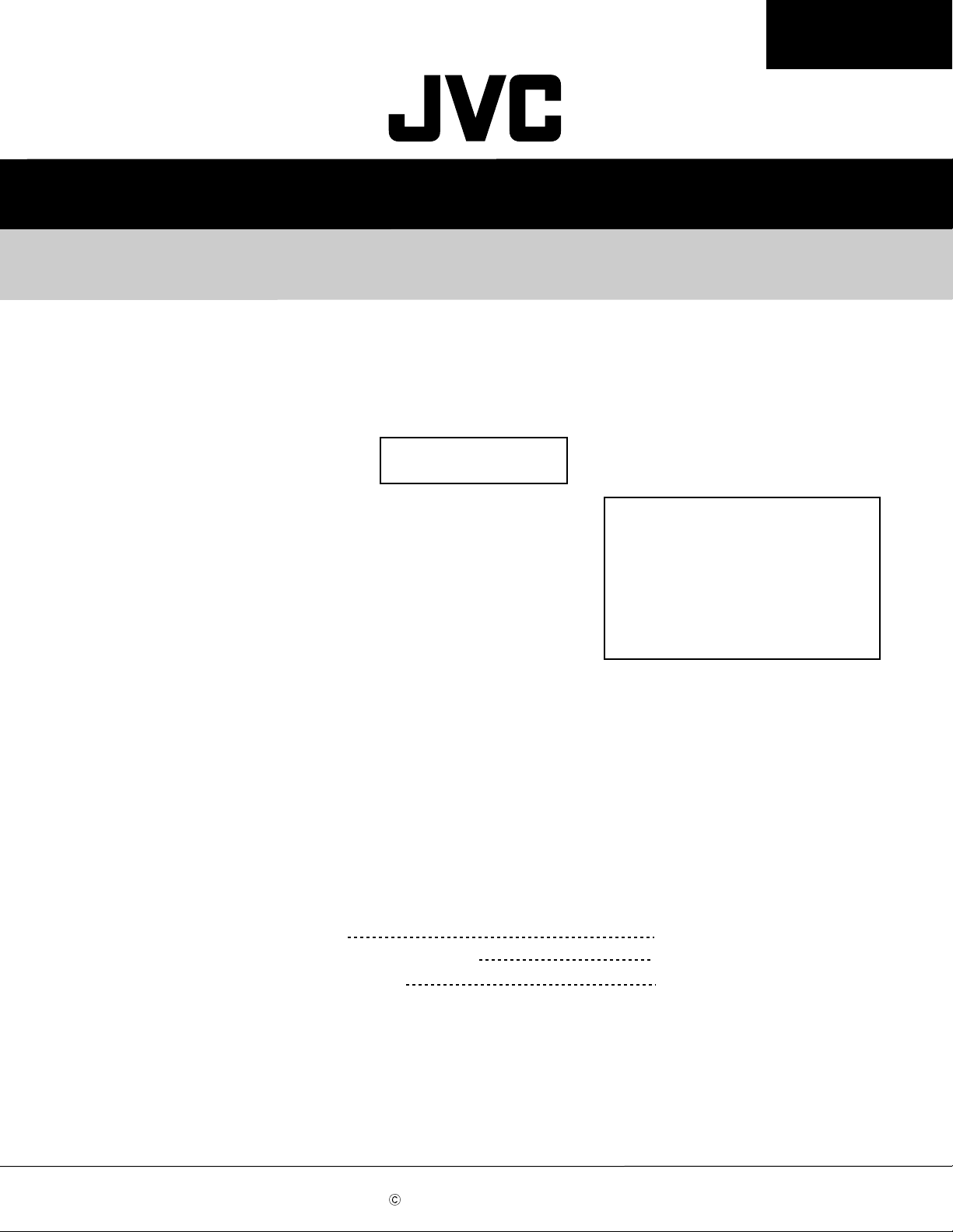
Block diagram
MX-DVA5
H/ P
5
HCW2
OCW
RCW6
HCW3
TO TUNER
FCW1UCW6
REMOCON
STAND-BY
USW1
USW2-6
FCW3
FIC4/ HIC1
BA4560X2
MICOM
LC86P6548
UCW5
UCW1
OP/ CL
USW7
4
AUX
UCW3
VFD
UX1 UX2
MASTER
VOLUME
SOURCE
74HCU04
OIC1
D.OUT
SELECTOR
& E.VOL
TDA7442D
FIC1
VOICE IC
M65855
TAPE IC
ECW1
UCW4
UCW2
UCW7
BASS
LEVEL
KA22291
SOUND
3
RW2 FCW2
VCW1
KCW1
KCW2 JCW2
JCW1
KEY
LEVEL
USW8-14.19.20
30-32
ACW2
CW301
ACW1 ACW3
CW302
AUX9 TUNER10
CD11 TAPE12
STK
B- B+ B-
402-
2
040
TO SPEAKER TO WOODER
STK
402-
090
MIC AMP
BA3837
KEY2
USW15-18.21-29
MCW1
MCW2
MCW3
ACW4
MIC JACK
LCW8
LCW5
LCW2
LCW6
TAPE-DECK
LCW1
LIC10
7808
1
LIC8
78R33
LIC7
78R05
LIC6
78R05
LIC9
78R08
LCW4
A-DECK B-DECK
FAN
POWER
-SUPPLY
CIRCUIT
POWER
TRANS
LCW7
ABCD E F G
2-1
Page 4
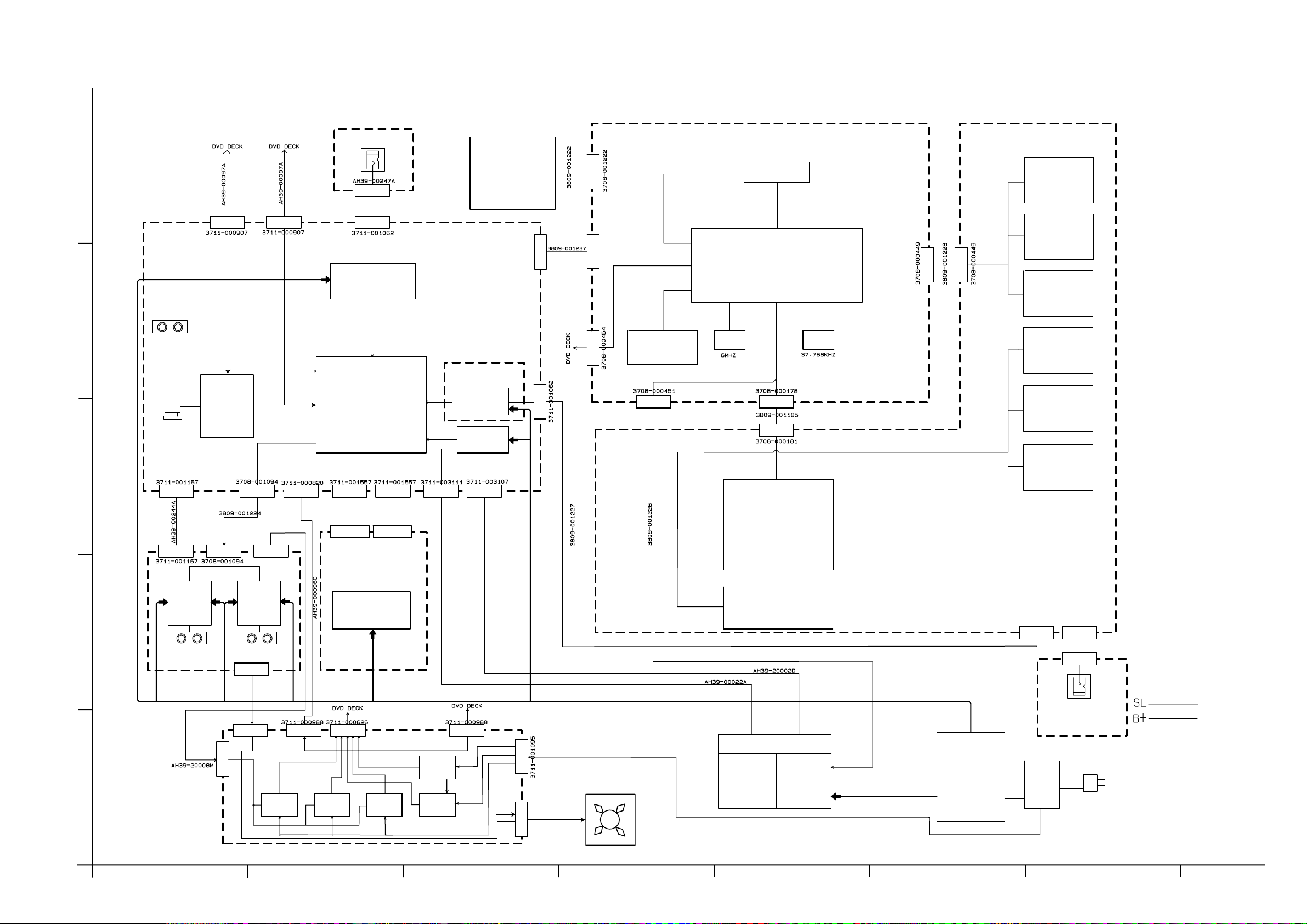
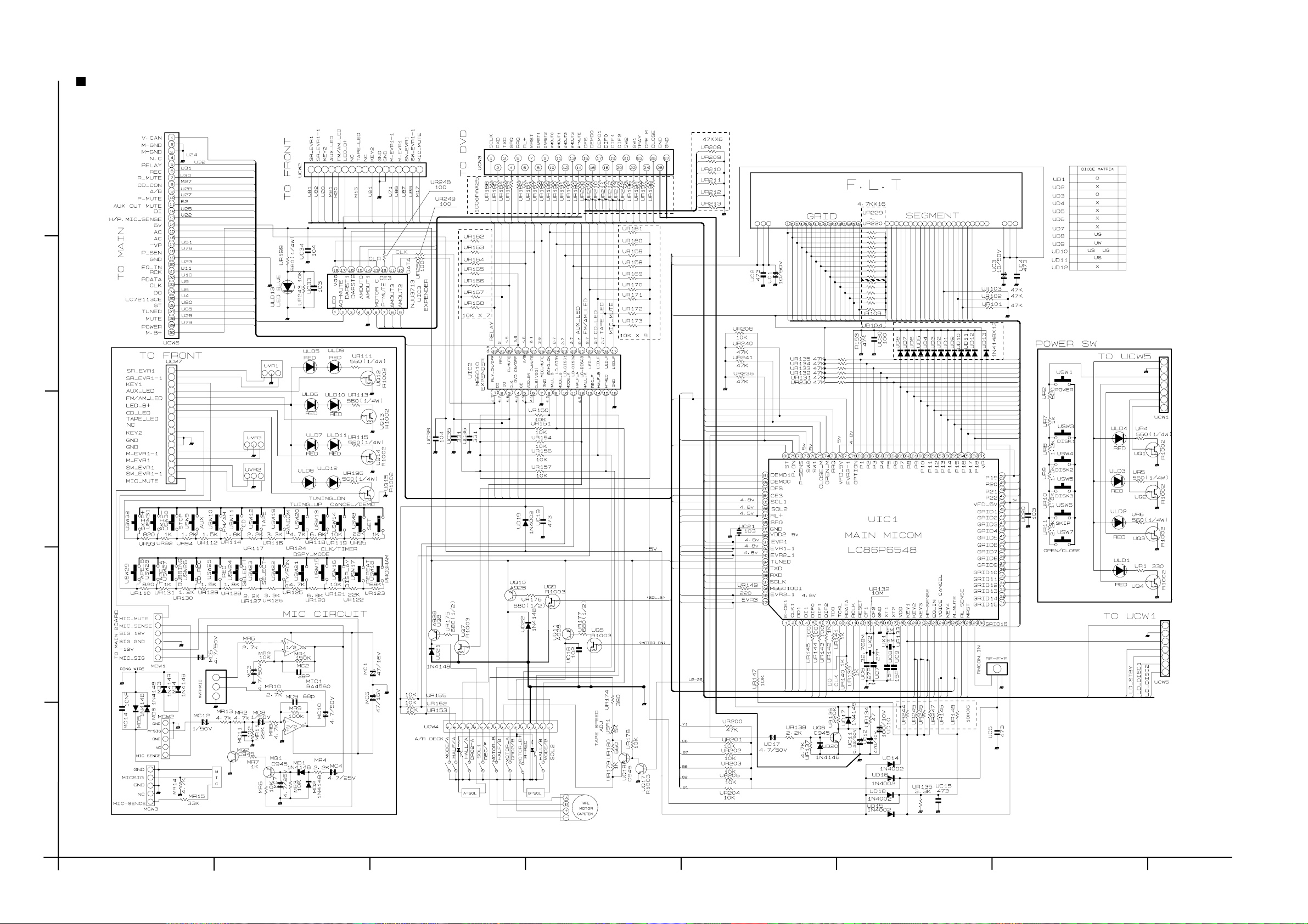
Standard schematic diagrams
Main section
5
TO SHEET 3/7 A-5 UCW6
4
MX-DVA5
MX-DVA5
TO SHEET 2/7 A-5 ACW1
MAIN signal
PRE MAIN signal
TUNER signal
CD signal
TAPE P.B. signal
TAPE REC. signal
TO SHEET 5/7 H-4 DCW1
TO SHEET 2/7 A-4 ACW2
3
TO SHEET 3/7 A-2 MCW1
TO SHEET 5/7 H-2 ACW4
TO SHEET 2/7 G-5 LCW4
2
1
TO SHEET 2/7 F-3 LCW5
Parts are safety assurance parts.
When replacing those parts make
sure to use the specified one.
2-2
SHEET 1/7
HABC DEFG
Page 5
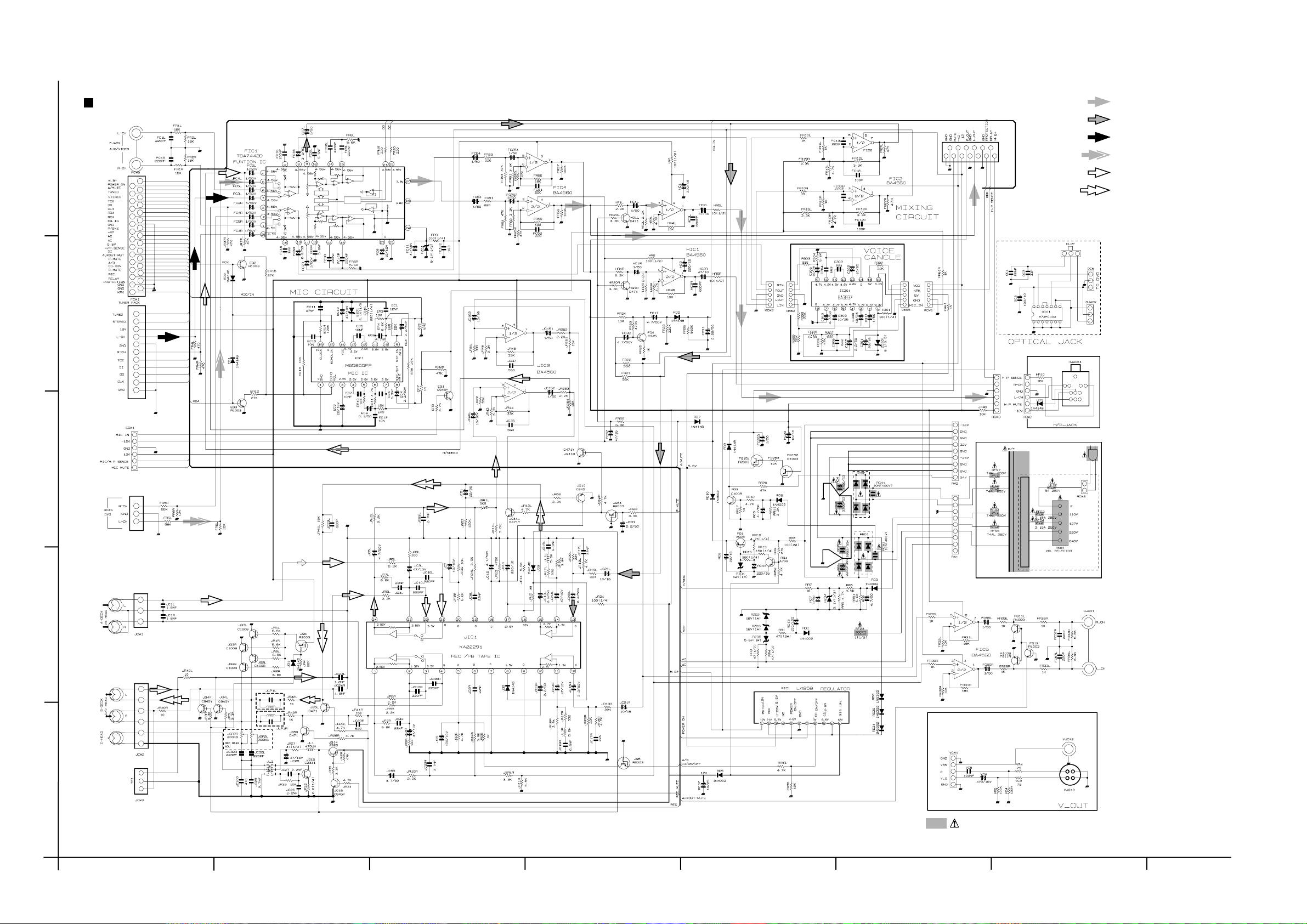
MX-DVA5
Amplifier section
TO SHEET 6/7 H-5 CW1
5
TO SHEET 1/7 F-5 FCW2
TO E-4 LCW1
TO A-4
TO SHEET 1/7 G-3 P.T
4
TO SHEET 1/7 F-1
TO SHEET 1/7 F-3 RW2
TO SHEET 5/7 F-4 VCW2
3
2
MAIN Signal
Parts are safety assurance parts.
When replacing those parts make
sure to use the specified one.
1
SHEET 2/7
ABCD E F G
2-3
Page 6
Front control section
MX-DVA5
MX-DVA5
TO UCW7
TO SHEET 5/7 A-1
5
1 2 3 4 5 6 7 8 9 10 11 12 13 14 15 16 17 18 19 20 21 22
TO SHEET 1/7 A-5 FCW1
4
TO UCW2
3
2
TO SHEET 1/7 A-3 ECW1
1
2-4
SHEET 3/7
HABC DEFG
Page 7

MX-DVA5
Micom & MPEG section
5
TO SHEET 6/7 H-6
DRAM
4
CMOS LOGIC
EPROM
3
TO SHEET 7/7 H-4
TO SHEET 6/7 H-2
2
EEPROM
MICRO CONTROLLER
CMOS LOGIC
CMOS LOGIC
DRAM
TO SHEET 5/7 A-4
TO SHEET 3/7 D-5 UCW3
1
SHEET 4/7
ABCD E F G
2-5
Page 8

Audio & Video signal out section
MX-DVA5
MX-DVA5
DL3
+5D
10uH
VL100
10uH
5
104
VC104
4443424140393837363534
4443424140393837363534
1
2
3
VIC50
4
5
SAA7128
6
7
8
VIDEO ENCODER
9
10
(D/A CONVERTOR)
11
1213141516171819202122
1213141516171819202122
VR113 100
VR112 100
VR111 100
VR110 100
VR114 100
VD4
VD3
VD2
VD1
VD0
AR61
22K
D-8V
VC103
VC101
104
104
VR15 4.7K
VR16 4.7K
104
VC105
VR101
4.7K
VB1
33
33
32
32
31
31
Y
30
30
29
29
28
28
VBS
27
27
26
26
25
25
C
24
24
23
23
+
104
VC105
VE69
220u/16V
DVCC(+5V)
AUDIO INPUT
DGND
104
AC1
AIC1
VR177 430
VR178 430
VR176 430
+
100u/16V
AE18
DATA0
201918171615141312
201918171615141312
D/A CONVERTOR
123456789
123456789
DIF2
DIF0
DEM
VFC2
VFC1
VFC3
22p
22p
AF1
F-BEAD
104
AC2
BCK
11
11
10
WM8720EDS
10
33K
33K
33K
VR11
VR201
VR200
VFR3 000
VFR2 000
VFR1 000
22p
5.6K
5.6K
5.6K
VR14
VR13
VR12
AR6
10K
+
104
AC3
10u/16V
AE3
AR13
10K
1
2
3
4
5
6
7
8
680pF
AC4
680pF
AC8
VIC52
BA7660FS
1
2
3
4
5
6
7
8
AR9
10K
AR14
10K
16
16
15
15
14
14
13
13
12
12
11
11
10
10
09
VIDEO AMP
09
AC7
1500pF
AR10
10K
AC7
1500pF
AR15
10K
VC2
104
VE66
+
470u/16V
100pF
AC6
AC9
100pF
VC106
104
AU-GND
+
VE51
VR193
75
AIC5
BA4560
47u/16V
A+8V
48
1
-
2
+
A-8V
AUDIO AMP
5
-
6
+
BLM21A121S
VIDEO OUTPUT
(S-Y)
(S-C)
(Video)
104
AC24
3
104
AC5
7
1
2
3
4
5
VCW2
WAFER-5P
VBS
C
GND
V-OUT
GND
+5D
+5A
VL8
BLM21A121S
TO SHEET 2/7 F-4 LCW6
OR37
AE4
AR11
+
100
22u/16V
AE5
AR16
+
100
22u/16V
AR18
330
47K
OE1 100u/10V
OC9
104
7
1 2
14
VD-GND
+
AR12
47K
OPTICAL OPTION
AIC5A
M74HCU04
3 4
AR17
1K
AR19
1K
MUTE
5 6
AQ1
B
AQ2
B
C1623
C1623
CE
EC
9 8
11 10
13 12
AR78
100
AR77
100
OR1
33
AUDIO OUTPUT
AUDIO OUTPUT
DCW1
3P
1
+5VD
TO OCW
2
GND
3
OPT OUT
TO SHEET 1/7 G-4
ACW4
3P
1
DM-R1
2
GND
3
DM-R2
TO SHEET 1/7 A-3 RCW6
VIDEO Signal Flow
AUDIO Signal Flow
VC100
104
3.3V
D+8V
1
2
3
4
5
6
7
8
9
10
11
AGND
1
2
3
4
11
5
*VSYNC
6
*HSYNC
7
VD7
8
VD6
9
VD5
10
TO SHEET 4/7 G-6
4
TO ZIVA-3 VIC1
OPTICAL
VD4
11
VD3
12
VD2
13
VD1
14
VD0
15
16
DATA0
17
18
19
20
21
22
23
24
25
VR57 100
VD-GND
VD-GND
VC79
22p
*VSYNC
*HSYNC
VD7
VD6
VD5
VIDEO INPUT
AC68
103
10
3
ARR1 1
TO SHEET 6/7 H-3
1
2
ARR2 1
+
AE1
100u/16V
+
AE2
100u/16V
TO SERVO PARTSTO FRONT M-COM
D+8V
E
AQ15
B
KSR1103
AQ16
AMOUT0
2
1
PO-MUTE MUTE
2
DFS
3
DEM00
4
TO SHEET 3/7 D-5 UCW3
DEM01
5
DIF0
6
DIF1
7
DIF2
8
E
B
C
KSR1103
AD-GND
D+5V AD-GND
C
AR69 180
1 2
VC2
104
VC2
104
AR63 2.2K
AC55
104
AIC9A
7S04
DEM
A+8V
AD-GND
A-8V
DAN202
AD4
SHEET 5/7
1
2-6
HABC DEFG
Page 9

Servo & DSP section
MX-DVA5
5
MOTOR DRIVER
DRAM
TO SHEET 4/7 A-4
TO SHEET 4/7 A-4
ASIC
4
MOTOR DRIVER
MOTOR DRIVER
3
TO SHEET 2/7 E-5
TO SHEET 5/7 A-3
TO SHEET 7/7 H-1
TO SHEET 7/7 H-2,3
2
ASIC
VOLTAGE COMP
MOTOR DRIVER
1
TO SHEET 4/7 A-2
SHEET 6/7
ABCD E F G
2-7
Page 10

RF section
RC47
104
MX-DVA5
MX-DVA5
5
RD7
DAN202
RR63
000
1
2
3
4
5
6
7
8
104
RC43
DGND
ENVB
ENVP
ABCDI
RR14 12K
RIC2
RC13
224
+
DGND
16
15
14
13
12
74VHC4053
11
10
9
RL3
BLM21A121S
RE12
47u/16V
PD-CD
LDO-CD
RC50 104
16
15
14
13
12
11
10
9
DGND
RR53
000
RR23 100K
RR23 100K
104
RC15
DVCC
AGND
PD-DVD
RR6
6K
104
10K
RR5
6.2K
RC5
RR4
RIC3
KA2903DTF
2/2
15K
RR67
RFDVCC
VREFEQ
AGND
RFDVCC
RR73A
510K
7
RFDECT
RR69 000
1
2
3
4
5
6
7
8
ANALOG MULTI PLEXER
RC21
RR51
RFRP
33K
DGND
RFCT
+
RE2
10u/16V
RC44
RR40
27K
100
RC1
15p
104
76
76
77
77
78
78
79
79
80
80
81
81
82
82
83
83
84
84
85
85
86
86
87
87
88
88
89
89
90
90
91
91
92
92
93
93
94
94
95
95
96
96
97
97
98
98
99
99
100
104
RR32 100K
RC16 104
+
RE13 10u/16V
STB
MD
MC
RC22
75747372717069686766656463626160595857565554535251
RR31 8.2K
104
75747372717069686766656463626160595857565554535251
RR30
VREFO
1K
1K
3.3K
RR65
DPDEQ1
DPDEQ2
BCA
FAULT
12K
RR29
RR28
RR25
RIC1
KS1461
RF AMP.
12345678910111213141516171819202122232425
12345678910111213141516171819202122232425
104
RC3
RR1 15K
RR2 15K
RR3 15K
RC53 104
RC52 104
RC51 104
RC50 104
VC
VB
VA
RC3
VD
12K
FOFST
104
PLLDFCT
RFDFCT
RFDVCC
RC16
+
RFDVCC
104
DGND
50
50
49
49
48
48
47
47
46
46
45
45
44
44
43
43
42
42
41
41
40
40
39
39
38
38
37
37
36
36
35
35
34
34
33
33
32
32
31
31
30
30
29
29
28
28
27
27
26
26
RR33 3.3K
RE8
10u/16V
VREFO
RR73A
510K
RC46
224
RR45
10K
224
RC46
RC17 104
VOLTQAGE COMP
5
+
6
-
RR59
3.3K
39K
RR73
VREFO
VREFO
RC45 474
RFDVCC
RR59
3.3K
RC47
4.7K
OP AMP.
4
RIC4
BA4560
3
+
2
1
-
3
RFEQO
RQ2
B
KSR1103
2
RFDVCC
RR41 3.9K
E
C
RE17
47u/16V
+
RC29
RR42 10K
104
RC31 104
RR43 10K
RR44 10K
RC33 104
RR68 18K
RR69 15K
RR70 33K
RC34 104
RR47 100K
RC35 101
RR48 100K
RC36 152
RR49 4.7K
RC37 104
RR56
7.5K
RR57
RC47A
224
AGND MROFST
1
2
RFDVCC
104
RIC3
+
-
RR36 100K
RC25 104
RR37 100K
RC26 104
RR38 100K
RC27 104
RR39 100K
RC28 561
RR72
510K
KA2903DTF
3
DGND
1/2
RR34 10K
RR35 15K
RC24 82p
RC32
104
AGCLVL
AGCB
RC38
104
RD6
DAN202
RFAGCO
RR7
47
RR23 100K
RC39 272
RR22 100K
RC12 224
RR21 2.7K
RR20 4.7K
RC11 104
RC10 103
RR19 100K
RC9 103
RR18 100K
FOKB
ENV
VREFO
AGND
RR24 1K
LDO-DVD
RFDVCC
RC43
102
RC14
TO SHEET 4/7 A-2
MIC1 (79)
RC40
103
AGND
MIC1 (90)
MIC1 (97)
MIC1 (21)
MIC1 (22)
MIC1 (20)
MIC1 (98)
MIC1 (99)
SIC1 (34)
TO MIC1
DGND
RFDVCC
RFAVCC
SR33 (SIC1_78)
SIC1 (59)
SIC2 (1)
SR32 (SIC1_79)
SIC3 (2)
SIC1 (38)
MIC1 (96)
SIC1 (66)
RR17 15K
RC8
15p
RR15 3.6K
RC7 391
RR12 20K
RR10 8.2K
FE
RC6 561
VREFO
RR16 3.6K
RR13 8.2K
RR11 2.4K
SCW1 (12)
1
5
TO SHEET 1/7 H-2
2
TO SHEET 6/7 H-3
TO DECK BOARD
SR21 (SIC1_64)
SR22 (SIC1_65)
SCW1 (17)
SCW1 (16)
SCW1 (12)
SCW1 (7)
SCW1 (9)
SCW1 (8)
SCW1 (6)
SCW1 (13)
SCW1 (10)
RL3
BLM21A121S
+
104
RE9
47u/16V
AVCC
TO DIC1
DIC1 (73) RR46
DIC1 (80) RR50
DIC1 (81) RR62
Focus Servo Control Signal Flow
Track Servo Control Signal Flow
Audio/Video Signal Flow
3
TO SHEET 6/7 H-2
4
TO SHEET 6/7 H-3
1
PWM2
PWM1
PWM0
SHEET 7/7
2-8
HABC DEFG
Page 11

Printed circuit boards
Main board
5
MX-DVA5
+
+
+
+
+
+
+
4
3
+
+
+
+
+
+
+
+
+
+
+
+
+
++
+
+
+
+
+
+
+
+
+
+
+
+
+
+
+
+
+
+
+
+
+
+
+
+
+
+
+
+
+
+
+
+
+
+
+
+
+
2
+
+
1
ABCD E F G
+
+
+
+
+
+
+
+
+
+
+
+
+
+
+
+
2-9
Page 12

MX-DVA5
MX-DVA5
Amp. board (Reverse side)
5
+
4
+
+
3
+
+
+
+
+
+
+
+
+
+
+
+
+
+
+
+
++
2
+
1
+
+
++
+++
+
+
2-10
+
+
+
+
+
+
+
+
+
+
HABC DEFG
Page 13

MX-DVA5
Front board
Power / CD switch board
5
+
4
+
3
+
+
FL display & system control board
+
+
+
2
+
+
+
+
1
ABCD E F G
+
+
+
Front key switch board
+
+
2-11
Page 14

MX-DVA5
DVD board (Forward side)
5
4
MX-DVA5
3
2
1
2-12
HABC DEFG
Page 15

MX-DVA5
DVD board (Reverse side)
5
+
+
+
+
+
+
+
+
4
+
+
+
+
+
+
+
+
+
+
+
+
+
+
+
+
+
3
+
+
+
+
+
+
+
+
+
+
+
+
+
+
+
+
+
+
+
+
+
2
+
+
+
+
+
+
+
+
+
1
ABCD E F G
2-13
Page 16

MX-DVA5
MX-DVA5
DVD board (Reverse side)
5
Voice board
+
+
+
+
+
+
+
+
+
DVD power board
4
Headphones board
3
CD/ DVD drive board (CD/ DVD mechanism)
2
1
2-14
HABC DEFG
Page 17

< MEMO >
Page 18

MX-DVA5
VICTOR COMPANY OF JAPAN, LIMITED
AUDIO & COMMUNICATION BUSINESS DIVISION
PERSONAL & MOBILE NETWORK BUSINESS UNIT. 10-1,1chome,Ohwatari-machi,Maebashi-city,371-8543,Japan
(No.20966CSCH)
200203(V)
 Loading...