

Page 1
®
PROJECTOR
MANUEL D’INSTRUCTIONS : PROJECTEUR
DLA-M2000LU
DLA-M2000SCU
INSTRUCTIONS
ENGLISHFRANÇAIS
(Lenses are optional)
E
N
T
E
R
Page 2
INSTRUCTIONS
PROJECTOR
DLA-M2000LU
DLA-M2000SCU
Thank you for purchasing this projector. Before using it, read and follow all instructions
carefully to take full advantage of the projector’s capabilities.
ENGLISHDEUTSHFRANÇAISITALIANOESPAÑOL
1
Page 3
SAFETY PRECAUTIONS
IMPORTANT INFORMATION
WARNING :
TO PREVENT FIRE OR SHOCK HAZARDS, DO
NOT EXPOSE THIS APPLIANCE TO RAIN OR
MOISTURE.
CAUTION :
To reduce the risk of electric shock, do not remo ve cover.
Refer servicing to qualified service personnel.
This projector is equipped with a 3-blade groundingtype plug to satisfy FCC rule. If you are unable to insert
the plug into the outlet, contact your electrician.
FCC INFORMATION (U.S.A. only)
CAUTION:
JVC could void the user’s authority to operate the
equipment.
NOTE:
comply with the limits for a Class A digital device,
pursuant to Part 15 of the FCC Rules. These limits are
designed to provide reasonable protection against
harmful interference when the equipment is operated
in a commercial environment. This equipment
generates, uses, and can radiate radio frequency
energy and, if not installed and used in accordance
with the instruction manual, may cause harmful
interference to radio communications. Operation of this
equipment in a residential area is likely to cause
harmful interference in which case the user will be
required to correct the interference at his own
expense.
About burning-in of the D-ILA device
Do not allow the same still picture to be projected for a long
time or an abnormally bright video picture to be projected.
Do not project video images with high-intensity or highcontrast on a screen. The video image could be burned in to
the D-ILA device.
Use special care when projecting video games or computer
program images. There is no problem with ordinary
video-cassette playback images.
About the installation place
Do not install the projector in a place that cannot support its
weight securely.
If the installation place is not sturdy en o ug h , th e projector
could fall or overturn, possibly causing personal injury.
Changes or modification not approved by
This equipment has been tested and found to
IMPORTANT SAFEGUARDS
Electrical energy can perform many useful functions. This
unit has been engineered and manufactured to assure your
personal safety. But IMPROPER USE CAN RESULT IN
POTENTIAL ELECTRICAL SHOCK OR FIRE HAZARD. In
order not to defeat the safeguards incorporated into this
product, observe the following basic rules for its installation,
use and service. Please read these “Important Safeguards”
carefully before use.
– All the safety and operating instructions should be read
before the product is operated.
– The safety and operating instructions should be retained
for future reference.
– All warnings on the product and in the operating
instructions should be adhered to.
– All operating instructions should be followed.
– Place the projector near a wall outlet where the plug can
be easily unplugged.
– Unplug this product from the wall outlet before cleaning.
Do not use liquid cleaners or aerosol cleaners. Use a
damp cloth for cleaning.
– Do not use attachments not recommended by the
product manufacturer as they may be hazardous.
– Do not use this product near water. Do not use
immediately after moving from a low temperature to high
temperature, as this causes condensation, which may
result in fire, electric shock, or other hazards.
– Do not place this product on an unstable cart, stand, or
table. The product may fall, causing serious injury to a
child or adult, and serious damage to the product. The
product should be mounted according to the
manufacturer’s instructions, and should use a mount
recommended by the manufacturer.
– When the product is used on a cart, care
should be taken to avoid quick stops,
excessive force, and uneven surfaces
which may cause the product and cart to
overturn, damaging equipment or causing
possible injury to the operator.
– Slots and openings in the cabinet are provided for
ventilation. These ensure reliable operation of the
product and protect it from overheating. These openings
must not be blocked or covered. (The openings should
never be blocked by placing the product on bed, sofa,
rug, or similar surface. It should not be placed in a built-in
installation such as a bookcase or rack unless proper
ventilation is provided and the manufacturer’s
instructions have been adhered to.)
For proper ventilation, separate the product from other
equipment, which may prevent ventilation and keep /
distance more than 23-
5
/8" (60 cm).
2
Page 4
– This product should be operated only with the type of
power source indicated on the label. If you are not sure
of the type of power supply to your home, consult your
product dealer or local power company.
– This product is equipped with a three-wire plug. This
plug will fit only into a grounded power outlet. If you are
unable to insert the plug into the outlet, contact your
electrician to install the proper outlet. Do not defeat the
safety purpose of the grounded plug.
– Power-supply cords should be routed so that they are not
likely to be walked on or pinched by items placed upon or
against them. Pay particular attention to cords at doors,
plugs, receptacles, and the point wher e they exit from the
product.
– For added protection of this product during a lightning
storm, or when it is left unattended and unused for long
periods of time, unplug it from the wall outlet and
disconnect the cable system. This will prevent damage
to the product due to lightning and power line surges.
– Do not overload wall outlets, extension cords, or
convenience receptacles on other equipment as this can
result in a risk of fire or electric shock.
– Never push objects of any kind into this product through
openings as they may touch dangerous voltage points or
short out parts that could result in a fire or electric shock.
Never spill liquid of any kind on the product.
– Do not attempt to service this product yourself as
opening or removing covers may expose you to
dangerous voltages and other hazards. Refer all service
to qualified service personnel.
– Unplug this product from the wall outlet and refer service
to qualified service personnel under the following
conditions:
a) When the power supply cord or plug is damaged.
b) If liquid has been spilled, or objects have fallen on the
product.
c) If the product has been exposed to rain or water.
d) If the product does not operate normally by following
the operating instructions. Adjust only those controls
that are covered by the Operation Manual, as an
improper adjustment of controls may result in damage
and will often require extensive work by a qualified
technician to restore the product to normal operation.
e) If the product has been dropped or damaged in any
way.
f ) When the product exhibits a distinct change in
performance – this indicates a need for service.
– When replacement parts are required, be sure the
service technician has used replacement parts specified
by the manufacturer or with same characteristics as the
original part. Unauthorized substitutions may result in
fire, electric shock, or other hazards.
– Upon completion of any service or repairs to this product,
ask the service technician to perform safety checks to
determine that the product is in proper operating
condition.
– The product should be placed more than one foot away
from heat sources such as radiators, heat registers,
stoves, and other products (including amplifiers) that
produce heat.
– When connecting other products such as VCR’s, and
personal computers, you should turn off the power of this
product for protection against electric shock.
– Do not place combustibles behind the cooling fan. For
example, cloth, paper, matches, aerosol cans or gas
lighters that present special hazards when over heated.
– Do not look into the projection lens while the illumination
lamp is turned on. Exposure of your eyes to the strong
light can result in impaired eyesight.
– Do not look into the inside of this unit through vents
(ventilation holes), etc. Do not look at the illumination
lamp directly by opening the cabinet while the
illumination lamp is turned on. The illumination lamp also
contains ultraviolet rays and the light is so powerful that
your eyesight can be impaired.
– Do not drop, hit, or damage the light-source lamp (lamp
unit) in any way. It may cause the light-source lamp to
break and lead to injuries. Do not use a damaged lightsource lamp. If the light-source lamp is broken, ask your
dealer to repair it. Fragments from a broken light-source
lamp may cause injures.
– Xenon gas is enclosed with high pressure inside the light-
source lamp (lamp unit) of this projector. If you drop or
impart a shock to the lamp, or discard it as is, there is the
possibility of explosion, leading to personal injury. Use
special care when handling the lamp. For any unclear
points, consult your product dealer.
– Do not “ceiling-mount” the projector to a place which
tends to vibrate; otherwise, the attaching fixture of the
projector could be broken by the vibration, possibly
causing it to fall or overturn, which could lead to personal
injury.
– Use only the accessory cord designed for this product to
prevent shock.
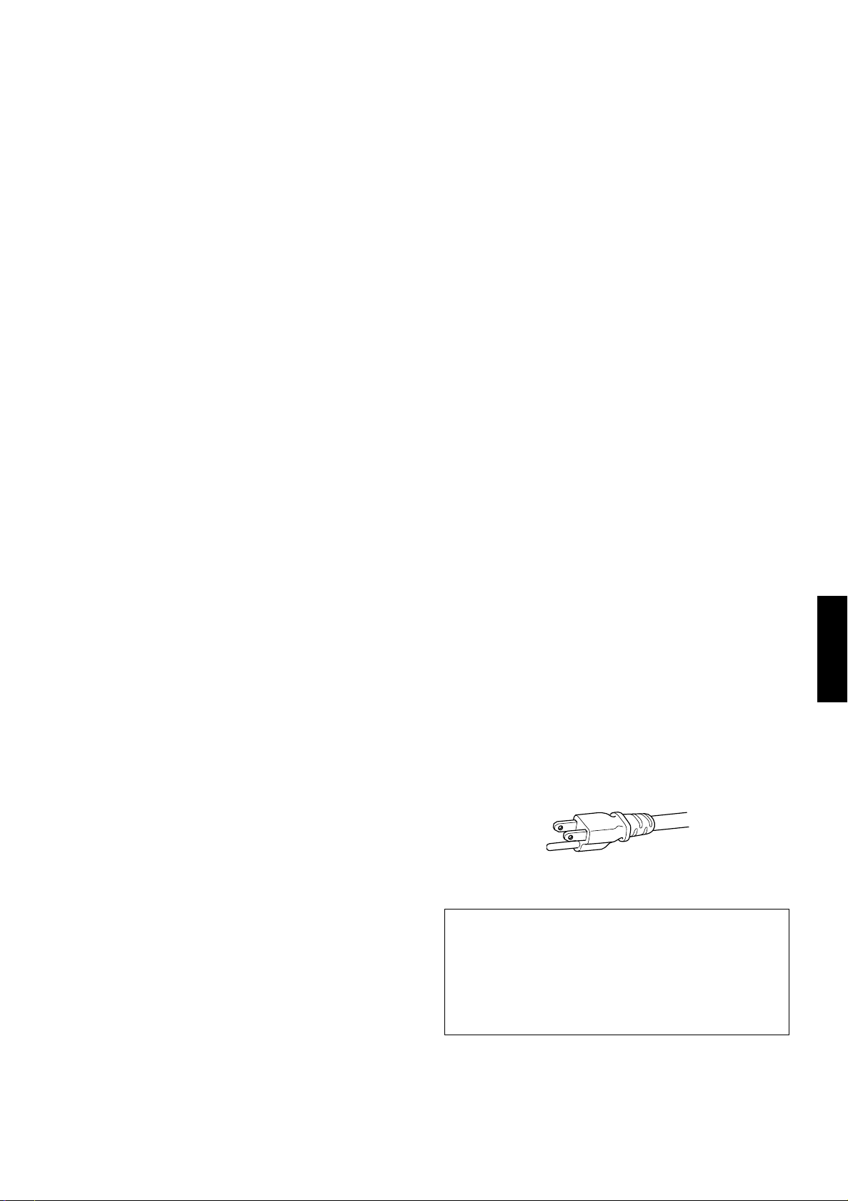
The power supply voltage rating of this product is
AC 120 V, the power cord attached conforms to the
following power supply voltage. Use only the power cord
designated by our dealer to ensure Safety and EMC.
When it is used by other power supply voltage, power
cable must be changed.
Ensure that the power cable used for the projector is the
correct type for the AC outlet in your country.
Consult your product dealer.
Power cord
Power supply voltage: AC 120 V
* DO NOT allow any unqualified person to
install the unit.
Be sure to ask your dealer to install the unit (eg.
attaching it to the ceilling) since special technical
knowledge and skills are required for installation.
If installation is performed by an unqualified person, it
may cause personal injury or electrical shock.
ENGLISHDEUTSHFRANÇAISITALIANOESPAÑOL
3
Page 5

Contents
SAFETY PRECAUTIONS ................. 2
Contents........................................... 4
Accessories ..................................... 5
Controls and Features .................... 6
Front Side / Top Surface / Right Side .....................6
Left-hand Side / Rear Side............ ... .......................7
Bottom Surface .......................................................8
Control Panel on the Projector................................9
Connector Panel ...................................................11
Remote Control Unit..............................................12
Installing Batteries.................................................14
Precautions for using batteries..............................14
Installing the Projector.................. 15
Precautions for Installation....................................15
Adjusting the Inclination of the Projector...............16
Installing the Projector against the Screen............17
Projection Distance and Screen Size....................18
Setting the Amount of Lens Shifting......................19
Effective Range and Distance of the
Remote Control Unit..............................................20
Setting the Position Selecting Screw for Ceiling
Mounting ...............................................................21
When installing (adjusting / setting) the unit..........21
Connecting to Various Devices.... 22
Signals that Can Be Input to the Projector............22
Connecting to Video Devices..... ... ........................24
Connecting to Hi-Vision Devices / DVD Players...25
Connecting to Other Devices................................26
Connecting to Devices which Control the
Projector................................................................27
Connecting to Computer Devices .........................28
Connecting the Power Cord..................................30
Removing the Lens Cap........................................30
Basic Operations........................... 31
1. Turning on the Power........................................31
2. Select the Input source to be Projected............32
3. Adjust the Screen Size (Zooming) ....................32
4. Adjust Focus ....................................... ... ...........33
5. Adjusting Sound Volume...................................33
Turning off Image and Sound (HIDE)....................34
Removing the Trapezoidal Distortion of the
Image....................................................................34
Quick Alignment Function (QUICK ALIGN.)..........35
Displaying a Still Picture (FREEZE)......................36
Zooming a Part of the Image
(DIGITAL ZOOM +/–)............................................36
Menu Operations ........................... 37
Basic Menu Operation...........................................42
Changing the Color System
(Video Menu Mode Only)......................................44
Changing the Language Display................ ...........45
Changing the Screen aspect ratio/HDTV format
(Video Menu Mode Only)......................................45
Adjusting Tracking / Phase ...................................46
Adjusting Picture Quality.......................................47
Adjusting Color temperature .................................48
Adjusting the Video Screen/Menu Position.......... 49
Changing the Image Tone/Aspect Ratio
(Video Menu Mode Only) ..................................... 50
Changing the Image Size - Resize Function
(PC Menu Mode Only).............................. ............ 51
Changing the Clamp pulse position
(PC Menu Mode Only).............................. ............ 51
Setting and Adjusting Other Functions
(OPTIONS)........................................................... 52
Getting Information............................................... 54
Replacing the Fuse........................ 55
Replacing the Light-Source
Lamp ...............................................56
Cleaning and Replacing the
Filter Cover..................................... 60
Troubleshooting............................. 61
Warning Indication......................... 63
Warning Messages ........................64
Specifications................................. 66
Outside dimensions.............................................. 67
Pin assignment (Specifications for terminals) ...... 68
RS-232C external control ..............69
Appendix......................................... 71
4
Page 6
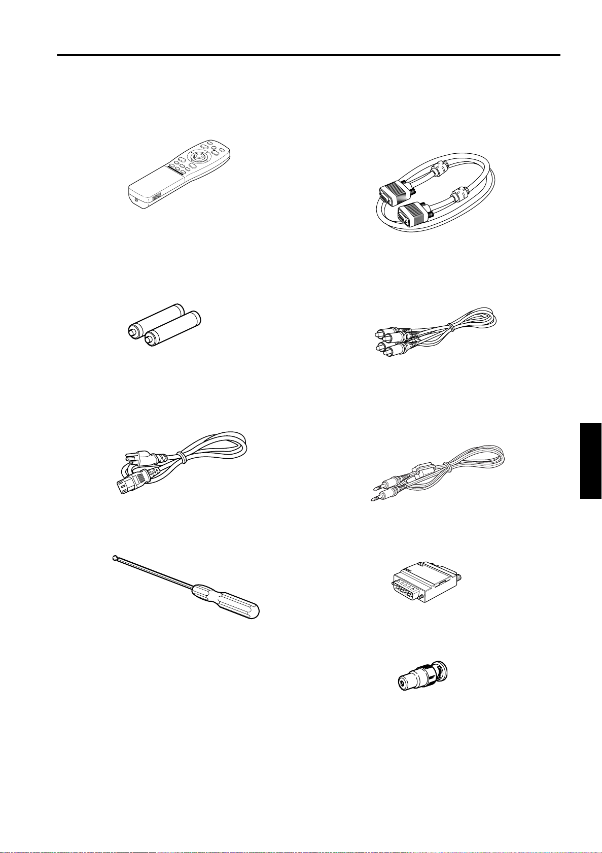
Accessories
The following accessories are included with this projector. Check for them; if any item is missing, please
contact your dealer.
Remote control unit (RM-M2000G)
■■■■
AA/R6-size dry cell battery (
■■■■
(for checking operation)
Power cord
■■■■
[approx. 8.2 ft (approx. 2.5 m)]
××××
Personal computer connection cable
■■■■
[approx. 6.56 ft (approx. 2 m)]
(D-sub, 3-row 15 pin)
Type : QAM 0104-002
2)
■■■■ AV connection cable
[approx. 6.56 ft (approx. 2 m)]
Type : QAM 0303-001
Remote cable
■■■■
[approx. 9.84 ft (approx. 3 m)]
(3.5 mm dia. stereo mini plug)
Type : QAM 0363-001
Hex. wrench
■■■■
Conversion adapter for Mac
■■■■
(for Macintosh)
BNC-RCA Conversion plug
■■■■
ENGLISHDEUTSHFRANÇAISITALIANOESPAÑOL
5
Page 7
Controls and Features
Front Side / Top Surface / Right Side
R
TE
N
E
NU
O
ME
E
D
I
V
C
P
PE
A
SC
E
E
TE
M
A
U
R
L
E
P
O
V
O
T
E
S
E
RE
N
P
O
T
S
IDE
Y
P
H
M
KE
TE
P
M
LA
9
8
7
6
5
4
3
1
2
1
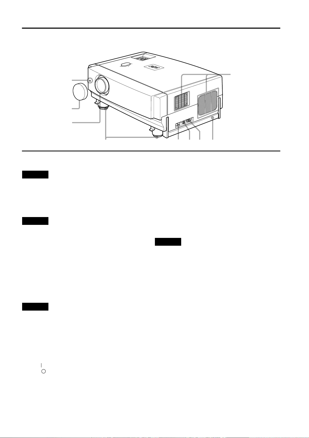
Exhaust vents
Vents for cooling fans through which warm air comes out.
CAUTION
• Do not block the exhaust vents, or heat will build up inside,
possibly causing a fire. Also, do not touch the vents, or this
could give you a low-temperature burn.
2
Carrying handle
Raise this handle when carrying the projector.
CAUTIONS
• When carrying the projector, do not transmit shocks to it.
Also be careful to keep it balanced.
• Do not carry it while the light-source lamp is on or the
cooling fan is operating. This could cause personal injury.
3
AC IN (power input) terminal
This is the power input terminal where the supplied
power cord is connected. For details, refer to page 30.
4
Fuse holder
A fuse rated 15A/250V is installed. (Power source
protection)
To replace the fuse, refer to page 55.
CAUTION
• When replacing the fuse, use the same rating and type.
Otherwise, a fire may occur and/or the projector may be
damaged.
5
MAIN POWER switch
This is the main power switch. When it is turned on, the
projector goes into stand-by state, and the STAND BY
indicator on the control panel comes on. (Refer to
page 31.)
ON [ ]: The main power turns on.
OFF [ ]: The main power turns off.
6
Adjustable feet (for adjusting the height and
angle)
By extending the feet, the projec to r an gl e can be
adjusted up to +7°.
For details, refer to “Adjusting the Inclination of the
Projector” on page 16.
7
Lens
One of the optional lens units should be installed before
using the projector.
A lens-hole blind cover (black one) is installed when the
projector is shipped from the factory.
For details on the types of optional lenses available, refer
to page 18.
CAUTION
• Please consult your authorized dealer or service center for
information about attaching an optional lens.
8
Lens cap
This is the lens cap provided for the optional lens.
When you are not using the projector, attach the lens cap
to protect the lens from dirt or being damaged. (Refer to
page 30.)
9
Remote sensor
When operating with the remote control, aim it toward
this sensor. (Refer to page 20.)
6
Page 8
Left-hand Side / Rear Side
L
A
M
P
T
E
M
P
S
T
A
N
D
B
Y
M
E
N
U
K
E
Y
S
T
O
N
E
V
O
L
U
M
E
P
R
E
S
E
T
E
S
C
A
P
E
E
N
T
E
R
O
P
E
R
A
T
E
p
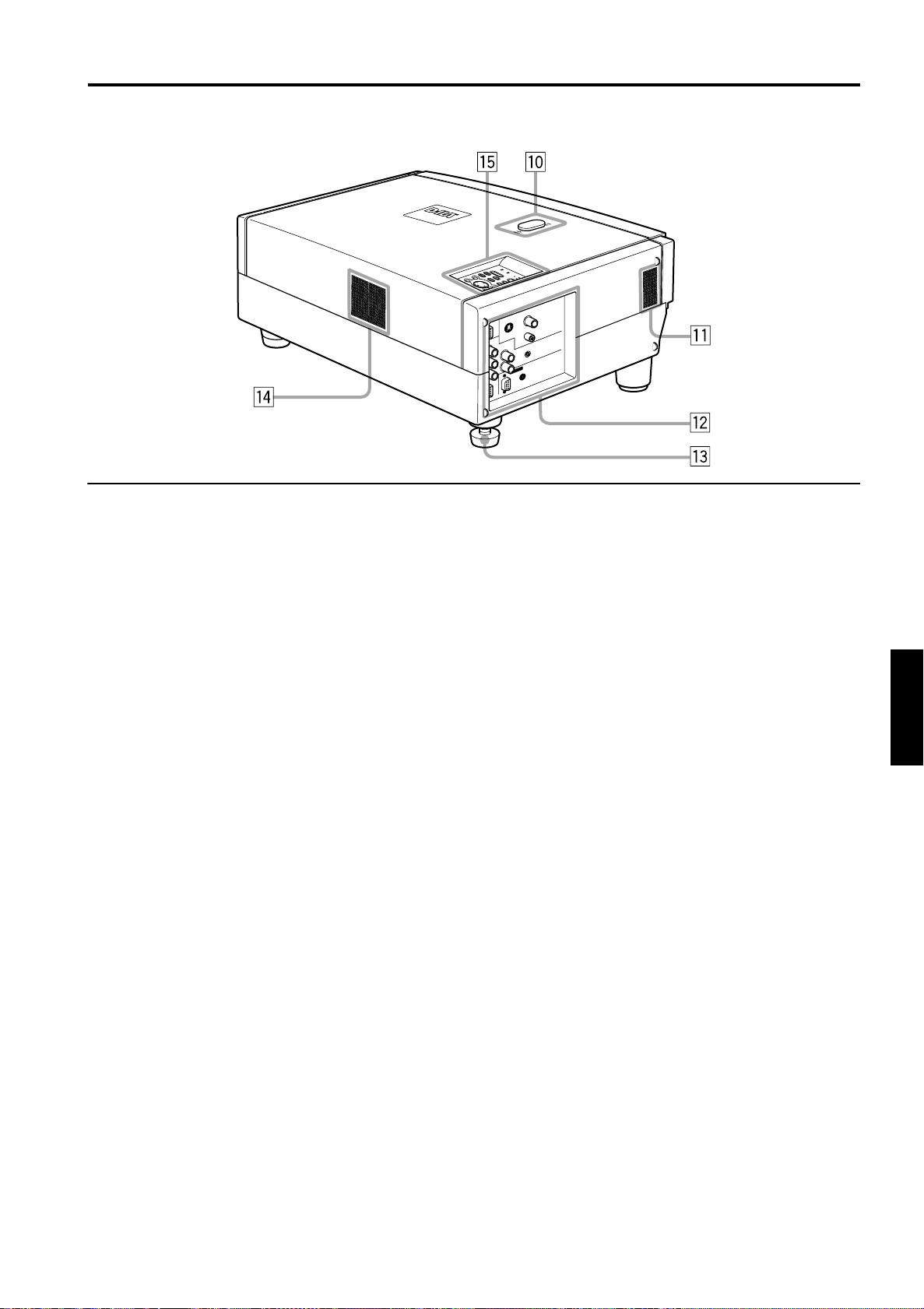
Lens shift knob cap
When you have mounted a lens that uses the lens shift
function, open this cap and rotate the lens shift knob to
move the lens position. For more information, refer to
“Setting the Amount of Lens Shifting” on page 19.
q
Speaker
This is the location of the built-in speaker.
w
Connector panel
For details, refer to “Connector Panel” on page 11.
e
Rear adjustable foot (for leveling the projector)
It is set at the shortest position when shipped from the
factory. Turn the foot to make the projector level.
Adjustment can be made in the range of +1.5° and –1.5°
from the horizontal position. For details, refer to
“Adjusting the Inclination of the Projector” on page 16.
r
Air inlet
This is the air inlet. Do not cover or obstruct this slot.
t
Control panel
For details, refer to “Control Panel on the Projector” on
page 9.
Controls and Features
U
P
D
O
W
N
H
I
D
E
P
C
V
I
D
E
O
ENGLISHDEUTSHFRANÇAISITALIANOESPAÑOL
7
Page 9
Controls and Features
Bottom Surface
o
y
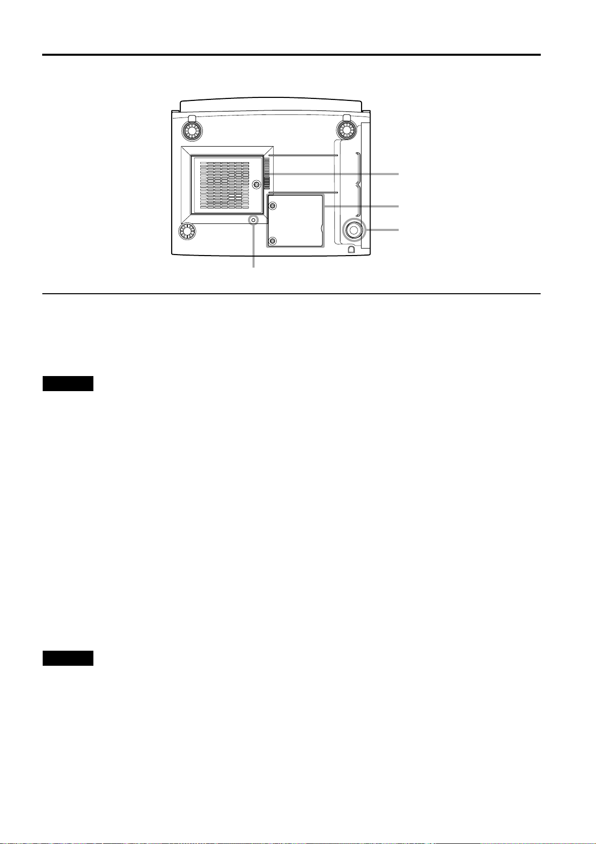
Air inlet (filter)
Air is taken in through the filter to cool the light-source
lamp. If the filter is blocked or if something that obstructs
the flow of air is placed around the projector, heat may
build up inside and could cause a fire. For required
space, refer to “Precautions for Installation” on page 15.
y
u
i
CAUTIONS
• Be careful as paper, cloth or soft cushion could be drawn in
if placed nearby. Do not block the filter, or heat may build
up and could cause a fire.
• Clean the filter periodically. For details, refer to “Cleaning
and Replacing the Filter Cover” on page 60. Deposition of
dirt on the filter reduces the cooling effect, causing heat to
build up inside, which could cause a fire or malfunction.
u
Opening for replacing the light-source lamp
For replacing the light-source lamp, refer to “Replacing
the Light-Source Lamp” on page 56.
i
Fixing foot
o
Position selecting screw for ceiling mounting
When using the projector in an upside-down, ceilingmounted position (inverted top-to-bottom and right-toleft), the “position selecting screw for ceiling mounting”
must be turned to switch to ceiling mounting.
This will correct variance in color images (shading),
which otherwise would occur in ceiling mounting.
For more information, refer to “Setting the Position
Selecting Screw for Ceiling Mounting” on page 21.
CAUTION
• To ceiling-mount and adjust the projector, special expertise
and technique are necessary. Be sure to ask your dealer or
specialist to perform this work.
8
Page 10
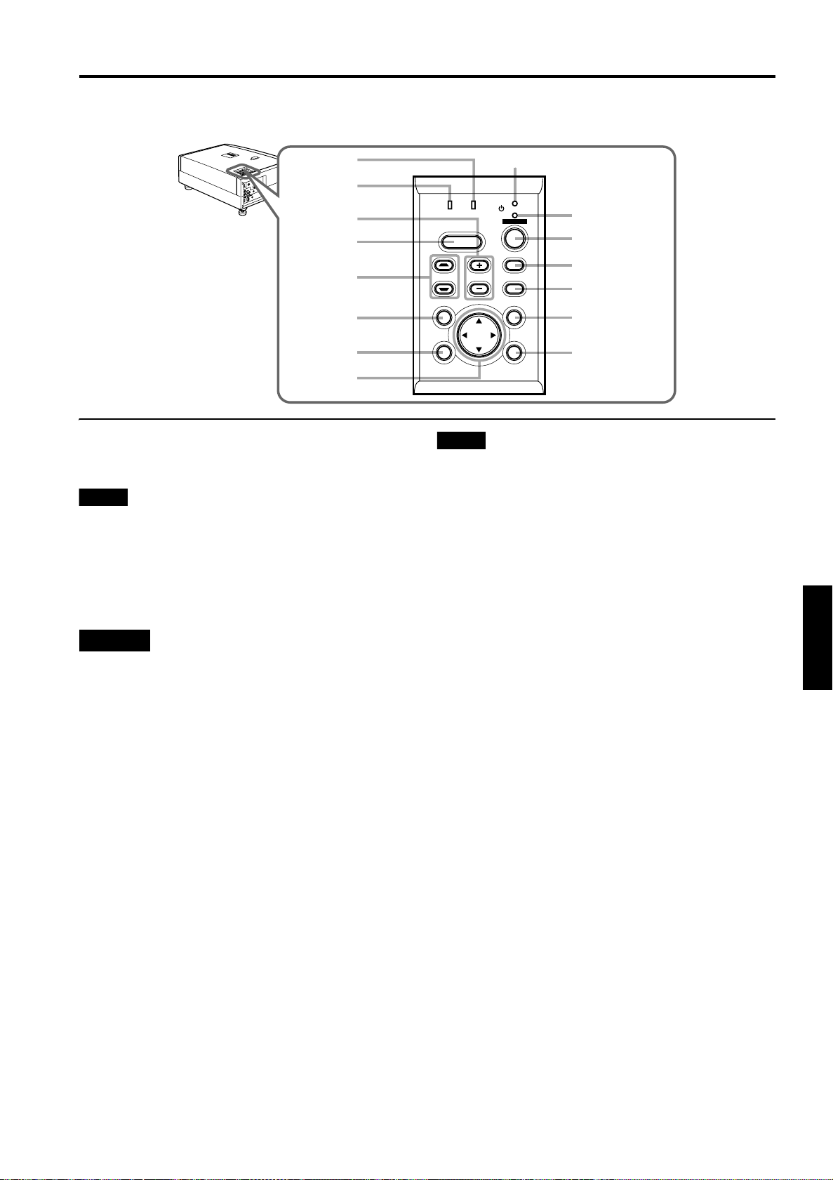
Control Panel on the Projector
LA
M
P
T
EM
P
S
TA
N
D
B
Y
M
E
NU
K
E
YS
T
O
N
E
V
O
LU
M
E
P
R
ESE
T
E
SC
A
P
E
EN
T
E
R
O
P
E
RA
T
E
U
P
D
O
W
N
H
ID
E
P
C
V
ID
E
O
t
r
e
w
q
p
LAMP TEMP
HIDE
KEYSTONE VOLUME
PRESET
1
STAND BY
OPERATE
PC
VIDEO
MENU
Controls and Features
2
3
4
5
6
9
8
1
STAND BY Indicator
ON : When in stand-by mode.
Blinking: When in cool-down mode.
Memo
About the cool-down mode:
This projector has a function to cool down the heated lamp for a
fixed period of time (approx. 120 seconds) after projection is
finished. This feature is referred to as the cool-down mode.
The purpose of the cool-down mode is to prevent inner parts
from being deformed or broken by heat from the heated lamp
as well as to prolong the life of the lamp.
CAUTIONS
• Do not turn off the MAIN POWER switch while in the cooldown mode.
• Do not place the projector on its side or stand it upright
while in the cool-down mode; this may block the vents.
2
OPERATE indicator
ON : When the projector is in operation (projecting).
OFF : When the projector is not in operation (not
projecting).
3
OPERATE button
When the projector is in the stand-by mode, press this
button one second or more, and the projector is turned
on, causing the OPERATE indicator to light.
Press it one second or more again, and the projector
goes into the cool-down mode, then stand-by mode.
(Refer to page 31.)
* You cannot use the OPERATE button for about one
minute after the lamp blinks. Press the button after a
minute or longer has elapsed.
ESCAPE ENTER
7
Memo
While in the cool-down mode (STAND BY indicator is blinking):
Even if you press the OPERATE button, the projector is not
turned on. Wait until the projector enters stand-by mode
(STAND BY indicator stays lit).
4
PC button
Use this button to select a device connected to the PC 1
or PC 2 terminals. Each time you press the button, the
selection alternates between PC 1 and PC 2.
* “PC1” or “PC2” will be displayed on the top right of the
projected image. (This function can be disabled by the
menu.)
5
VIDEO button
Use this button to select a device such as a video deck
connected to the AV IN (Y/C or VIDEO) terminal of the
projector. Each time you press the button, the selection
alternates between Y/C and VIDEO.
* “Y/C” or “VIDEO” will be displayed on the top right of the
projected image. (This function can be disabled by the menu.)
6
MENU button
Use this button to enter or exit the menu mode. The main
menu appears or disappears at the screen. For details,
refer to “Basic Menu Operation” on page 42.
7
ENTER button
This button will be used in the menu mode. Use to
display the hierarchical menus. Also use when “ENTER”
is displayed against the item on the menu screen or
when the “All reset” selection is confirmed. For details,
refer to “Basic Menu Operation” on page 42.
8
Cursor buttons 5/∞/2/
3
These buttons will be used in the menu mode to select an
item, or to set or adjust the value. For details, refer to
“Basic Menu Operation” on page 42.
ENGLISHDEUTSHFRANÇAISITALIANOESPAÑOL
9
Page 11

Controls and Features
9
ESCAPE button
This button will be used in the menu mode to return to the
previous menu. When the main menu is displayed, this
button will cause the menu to disappear. For details, refer
to “Basic Menu Operation” on page 42.
p
PRESET button
This PRESET button only works as a reset button for the
direct button adjustment of the VOLUME button and
KEYSTONE button of the control panel and the VOLUME
button and DIGITAL ZOOM button of the remote control.
When adjusting the volume, keystone or digital zoom
(when the setting is displayed on the screen) the
adjusted value is reset to that which was set when the
projector was shipped from the factory. Of the menu
items, this button only works for the keystone setting
screen.
q
KEYSTONE / buttons
Use these buttons to correct a trapezoidal distortion of
the projected image. (Refer to page 34.)
w
HIDE button
Use this button to turn off the image on the screen and
audio sound temporarily. Pressing it again restores the
image and audio sound to resume. (Refer to page 34.)
e
VOLUME +/– buttons
Use these buttons to adjust the sound volume:
+ : Increase the volume level. (0 → 50)
– : Decrease the volume level. (50 → 0)
(Refer to page 33.)
r
LAMP indicator
ON : After the light-source lamp has been used for
more than approx. 900 hours.
Blinking
t
TEMP indicator
Blinking : The temperature inside the projector has risen
: After the light-source lamp has been used for
more than approx. 1000 hours. Replace the lightsource lamp. Refer to
Source Lamp” on page 56
abnormally.
“Replacing the Light-
.
Note
• While the TEMP indicator is blinking (during abnormal
temperature), the power is automatically cut off.
10
Page 12
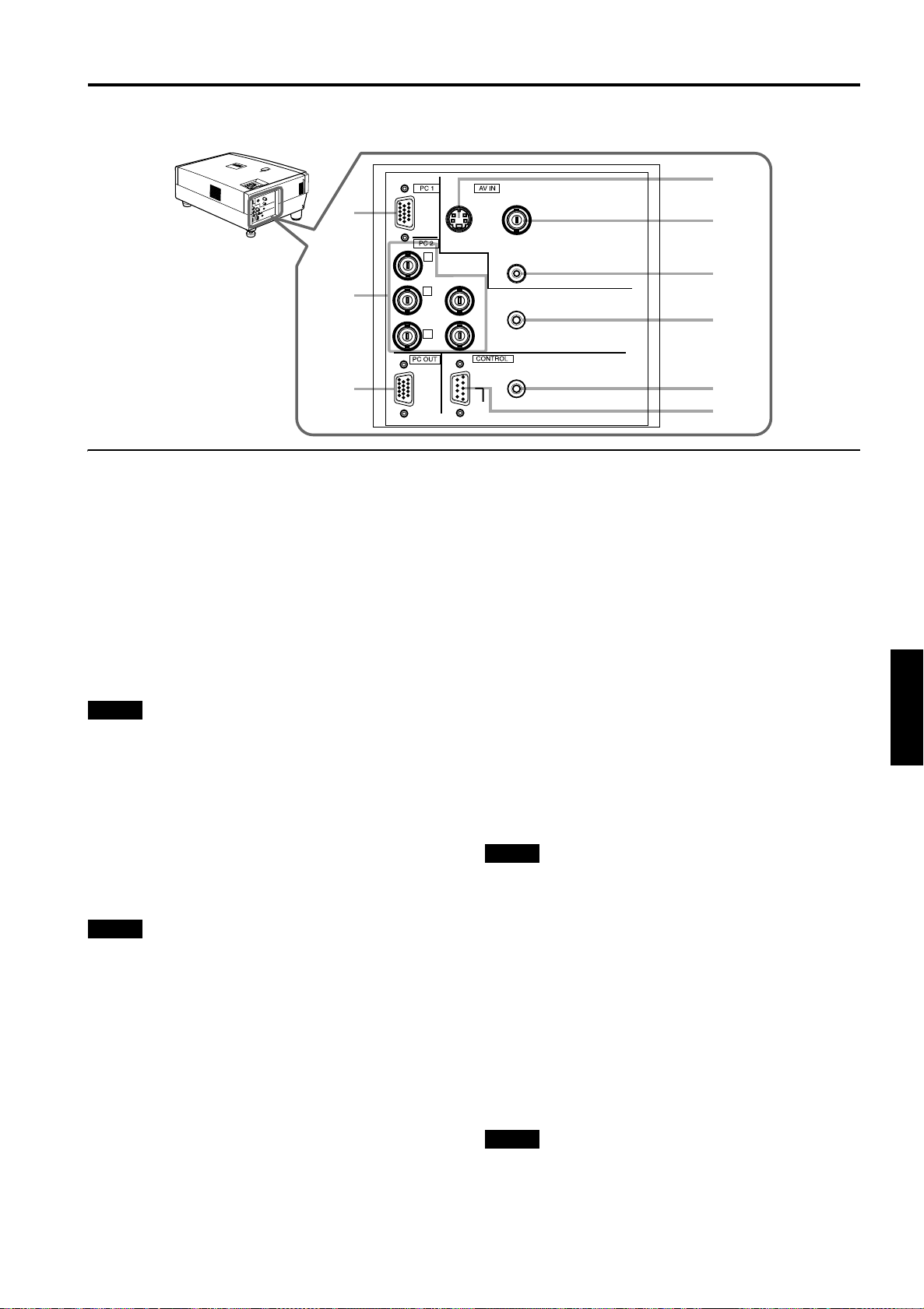
Connector Panel
L
A
MPTEMP
ST
A
ND B
Y
M
EN
U
KE
YS
TO
NE
V
O
LU
ME
P
R
E
SE
T
ESC
AP
E
E
N
T
ER
OP
E
R
ATE
U
P
D
O
W
N
H
IDE
PC
VI
DEO
9
Controls and Features
1
Y/C VIDEO
2
R
R/R-Y
P
P
G
Y
B
B/B-Y
8
7
1
Y/C (S-video) input terminal (Mini DIN 4 pin)
Connect this terminal to the S-video output terminal of a
video deck, etc.
2
VIDEO (composite video) input terminal (BNC)
Connect this terminal to the composite video output
terminal of a video deck, etc.
3
AUDIO input terminal (RCA pin jack)
This is a monaural-audio input terminal for devices
connected to the VIDEO IN terminals, such as a video
deck, etc. Connect the audio output signal of a device to
be used to this terminal. The input audio signal is
reproduced by the speaker of the projector.
Note
• When the video signal source (Y/C or VIDEO) is switched
with the VIDEO button, it is necessary to reconnect the
audio cable to the active device since the projector has only
a single AUDIO input terminal.
4
PC AUDIO (computer audio) input terminal (mini jack)
This is an monaural-audio input terminal for a device
connected to the PC 1 or PC 2 terminals. Connect the
audio output signal of a device to be used to this terminal.
The input audio signal is reproduced by the speaker of
the projector.
Note
• When the PC input terminal signal source (PC1 or PC2) is
switched with the PC button, it is necessary to reconnect
the audio cable to the active device since the projector has
only a single PC AUDIO input terminal.
5
REMOTE terminal (stereo mini jack)
To use the remote control as a wired unit, connect the
supplied remote cable between the remote control ’s
terminal and this jack. (Refer to page 20.)
* The remote sensor will stop working when the cable is
connected to the remote terminal.
6
RS-232C CONTROL terminal (D-sub 9 pin)
This is the RS-232C interface-specified terminal. The
projector can be controlled by a computer connected
externally.
* For details, refer to
page 27
and 69.
AUDIO
3
PC AUDIO
H
4
V
REMOTE
5
RS-232C
7
PC (computer) OUT terminal (D-sub 3-row 15 pin)
This is the terminal for video output from the monitor of
the computer connected to PC1 or PC2.
The computer input signal projected on the screen is
output. A display monitor can be used by connecting it to
this terminal.
8
PC (computer) 2 input terminals (BNC
These are multipurpose video input terminals that allow
input of the following signals.
• Analog RGB signals, vertical sync (V) signals, and
horizontal sync (H) signals / composite signals (Cs).
(Devices which have analog RGB signal output
terminals can be connected.)
* Input of external sync signals is automatically detected.
Detection of H/V signals or Cs signals causes automatic
switching to external sync. The priority order is H/V > Cs.
• Component signals (Y, B-Y, R-Y) or DTV-format (Y, PB,
PR) signals. (Devices which have component output
terminals can be connected.)
* For details about DTV-format signals (480i, 480p, 720p,
1080i) compatible with this unit, refer to
Notes
• In order to use this terminal, the input signal must be used to
select the “PC 2 (BNC)” setting in the option items of the menu.
Use the input signal to change the setting. (Refer to
• When computer-related signals are input, the uppermost
edge of the image may appear to bow if the sync signal
input is composite sync (Cs) or G on sync signal. In this
case, use separate sync signals for vertical sync (V) and
horizontal sync (H).
9
PC (computer) 1 input terminal (D-sub 3-row 15 pin)
This is an input terminal dedicated to computer signals
(RGB video signals and sync signals).
Connect the display output terminal of the computer to
this terminal. When a Macintosh computer is to be
connected, use the supplied conversion adapter for Mac.
Note
• When computer-related signals are input, the uppermost
edge of the image may appear to bow if the sync signal
input is composite sync (Cs) or G on sync signal. In this
case, use separate sync signals for vertical sync (V) and
horizontal sync (H).
6
×
×
5)
× ×
page 22
page 52
.
ENGLISHDEUTSHFRANÇAISITALIANOESPAÑOL
.)
11
Page 13
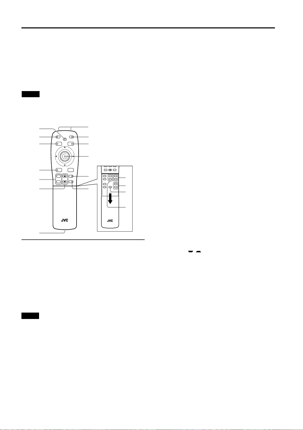
Controls and Features
Remote Control Unit
On the remote control, the same buttons as on the control
panel of the projector are provided except for the following
buttons. For the same buttons, operation is the same in
principle.
For remote control only:
DIGITAL ZOOM +/-, QUICK ALIGN., FREEZE, ZOOM T/W,
FOCUS +/-
Notes
• The ZOOM T/W buttons work only if the lens unit with a
zooming function is used.
• The following buttons are no t used with this projector.
VIC SELECT, SHIFT U/D, SHUTTER
e
w
q
FREEZE
PRESET
OPERATE
HIDE
MENU
E
N
T
E
R
1
2
3
4
p
9
8
ESCAPE
+
DIGITAL
ZOOM
–
KEYSTONE
VIDEO
PC
5
6
SHUTTER
DIGITAL
KEYSTONE
VIDEO
ZOOM
–
LENS
+
T
U
FOCUS
ZOOM
SHIFT
–
VOLUME
r
+
–
t
W
D
+
QUICK
ALIGN.
–
y
VIC SELECT
u
RM-M2000 REMOTE CONTROL UNIT
RM-M2000 REMOTE CONTROL UNIT
7
1
Remote control’s signal transmitter
2
OPERATE button
When the projector is in the stand-by mode, press this
button one second or more, and the projector is turned
on, causing the OPERATE indicator to light.
Press it one second or more again, and the projector
goes into the cool-down mode, then stand-by mode.
(Refer to page 31.)
* The OPERATE button will not work for approximately 1
minute from when the light-source lamp is turned on. Use
the button after approximately 1 minute.
Memo
While in the cool-down mode (STAND BY indicator is
blinking):
Even if you press the OPERATE button, the projector is not
turned on. Wait until the projector enters stand-by mode
(STAND BY indicator stays lit).
3
MENU button
Use this button to enter or exit the menu mode. The main
menu appears or disappears at the screen. For details,
refer to “Basic Menu Operation” on page 42.
4
Cursor (5/∞/2/3) /ENTER button
When using this as the cursor button, press it in the 5
/
2
3 directions to select menu items or adjust settings.
When using it as the ENTER button, press the button
straight down.
ENTER is used in the menu mode. Use to display the
hierarchical menus. Also use when “ENTER” is displayed
against the item on the menu screen or when the “All
reset” selection is confirmed. For details, refer to “Basic
Menu Operation” on page 42.
5
PC button
Use this button to select a device connected to the PC 1
or PC 2 terminals. Each time you press the button, the
selection alternates between PC 1 and PC 2. (Refer to
page 32.)
* “PC 1” or “PC 2” will be displayed on the top right of the
projected image. (This function can be disabled using the
menu.)
6
VIDEO button
Use this button to select a device such as a video deck
connected to the AV IN terminal (VIDEO or Y/C input
terminal) of the projector. Each time you press the button,
the selection alternates between Y/C and VIDEO. (Refer
to page 32.)
* “Y/C” or “VIDEO” will be displayed on the top right of the
projected image. (This function can be disabled by the
menu.)
7
Wired remote control terminal
To use the remote control as a wired unit, co nn e ct th e
supplied remote cable between this terminal and the
REMOTE terminal on the back of the projector. (Refer to
page 20.)
* The remote control’s signal transmitter will stop working
when the cable is connected to this terminal.
8
KEYSTONE / buttons
Use these buttons to correct a trapezoidal distortion of
the projected image. (Refer to page 34.)
9
DIGITAL ZOOM +/– buttons
A part of image can be magnified up to four times on the
screen.
Each time the + or – button is pressed, the image is
enlarged or the enlarged image is reduced by a certain
degree. (Refer to page 36.)
* Images which are enlarged with the digital zoom become
less clear.
* Depending on the video signal source (UXGA, etc.), this
button does not work.
p
ESCAPE button
This button is used in the menu mode to return to the
previous menu. When the main menu is displayed, this
button will cause the menu to disappear. For details, refer
to “Basic Menu Operation” on page 42.
/∞/
12
Page 14
q
PRESET button
This PRESET button only works as a reset button for the
direct button adjustment of the VOLUME button and
KEYSTONE button of the control panel and the VOLUME
button and DIGITAL ZOOM button of the remote control.
When adjusting the volume, keystone or digital zoom
(when the setting is displayed on the screen) the
adjusted value is reset to that which was set when the
projector was shipped from the factory. Of the menu
items, this button only works for the keystone setting
screen.
w
FREEZE button
During projection of an image on the screen, press this
button to obtain a still picture.
To restore normal projection, press it again. (Refer to
page 36.)
* Depending on the video signal source (UXGA, etc.), this
button does not work.
e
HIDE button
Use this button to turn off the image on the screen and
audio sound temporarily. Pressing it again makes the
image and audio sound to resume. (Refer to page 34.)
r
FOCUS +/– buttons
Use these buttons to adjust the focus of the projected
video image.
+: The focus point becomes more distant.
–: The focus point becomes nearer.
t
VOLUME +/– buttons
Use these buttons to adjust the sound volume:
+ : Increase the volume level. (0 → 50)
– : Decrease the volume level. (5 0 → 0)
(Refer to page 33.)
y
QUICK ALIGN. (Quick Alignment) button
Use this button to automatically align “Horizontal and
vertical position”, “Tracking” and “Phase” for the
projected image.
During the automatic alignment, “Quick Alignment”
appears on the screen, and disappears after alignment is
finished. (Refer to page 35.)
* The “Quick Alignment” function only works when the
signal is input from the input terminal of either PC 1 or PC
2. It does not work when the signal is input from the
VIDEO IN terminal (VIDEO or Y/C input terminal).
Controls and Features
ENGLISHDEUTSHFRANÇAISITALIANOESPAÑOL
CAUTION
• Automatic alignment with the quick alignment function
should be carried out on a bright still-picture. This function
may not work correctly on a dark picture or motion-picture .
If adjustment with this function is not satisfactory, adjust
“Horizontal and vertical position”, “Tracking” and “Phase” in
the menu mode.
u
ZOOM T/W buttons
Use these buttons to adjust the projected screen size.
(They work only if the lens uni t with a zoom ing funct ion is
used.)
T (Tele): The projected screen size decreases.
W (Wide): The projected screen size increases.
13
Page 15
Controls and Features
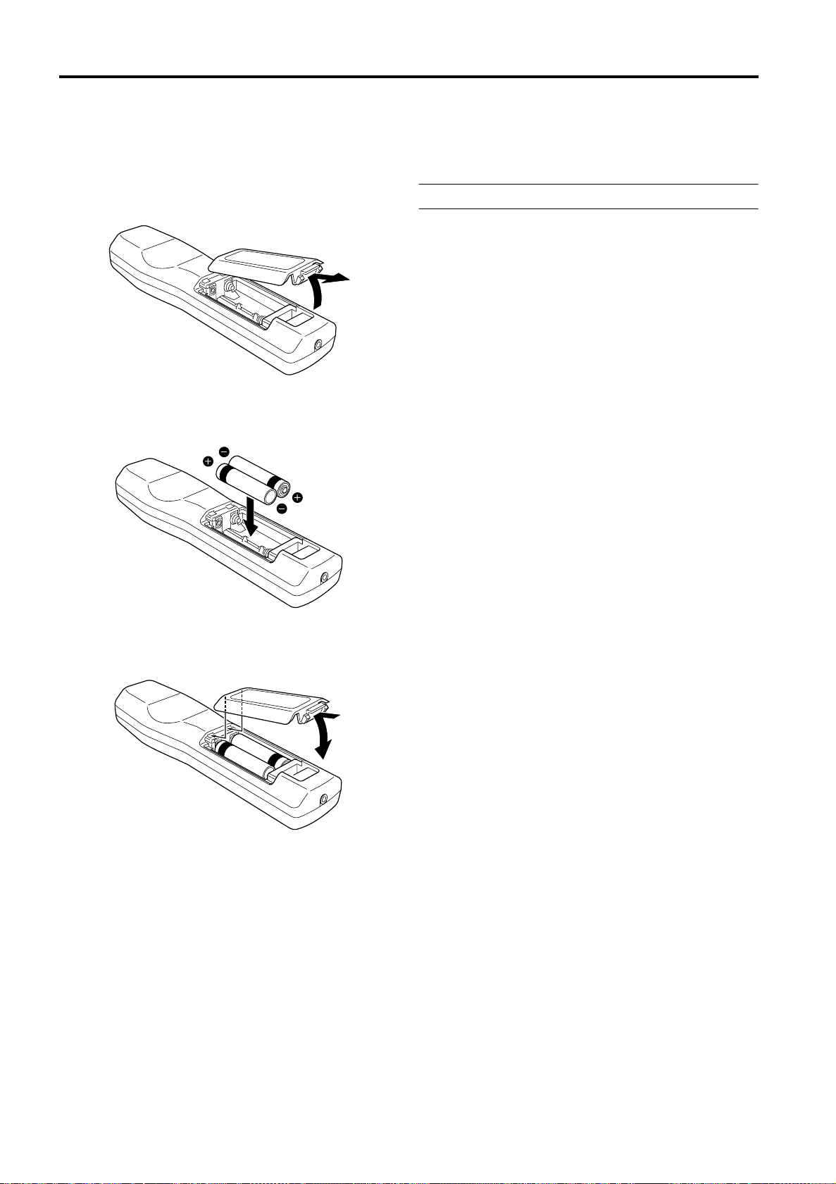
Installing Batteries
Install batteries in the remote control. If the remote control has started to work erratically, replace the
batteries.
Open the back cover.
1
Open the back cover in the direction of the arrow.
Install the batteries.
2
Place the two supplied batteries (AA/R6-size) in the
remote control as illustrated below.
Close the back cover.
3
First fit the claws on the back cover in the case, then
close the back cover in the direction of the arrow.
Precautions for using batteries
If batteries are used incorrectly, they may crack or
leak liquid. This could cause a fire, burn, malfunction,
or staining or damaging of the surroundings.
Beware of the following:
• Do not mix new and old batteries.
• Do not mix different types of batteries as they differ in
characteristics.
• Place batteries so they match the po l ar it ie s in d ic ated:
(+) to (+) and (–) to (–).
• Be sure to put the minus (–) end in first to avoid
short-circuiting.
• Use only designated batteries.
• Remove the batteries if the remote is not to be used for a
prolonged period.
• When the batteries are exhausted, replace them
immediately. Otherwise, liquid could leak, or malfunction
could occur due to leaking liquid. If the leaked liquid
contacts the skin, wipe it off with a cloth, otherwise the skin
could become rough.
• Do not put batteries into a fire or try to recharge them.
• Batteries run for six months to one year in normal use.
However, the batteries supplied are for confirming
operation and may not run that long. When the remote
control starts failing to work properly, replace the batteries
with new ones.
14
Page 16
Installing the Projector
Precautions for Installation
CAUTIONS
1. Before instalation, do not connect the projector’s power cord.
2. Do not install the projector in the following places:
• Where there is water, humidity or dust.
• Where the projector may be subjected to oil, smoke or cigarette smoke.
• On a soft surface such as a carpet or cushion.
• Where the projector may be subjected to direct sunlight.
• Where temperature is high or humidity is low.
Allowable operation temperature range: 41°F to 95°F (+5°C to +35°C)
Allowable relative humidity range: 20% to 80% (no condensation)
Allowable storage temperature range: 14°F to 140°F (–10°C to +60°C)
■
When installing the projector, observe the following:
• Do not use the projector placed on its side.
Avoid using the projector placed on its side. This could cause a malfunction.
• Use the projector within the specified angle.
Do not use the projector inclined ±30° horizontally (left/right). This could cause color variation or shorten the lamp life.
• Do not block the exhaust vents.
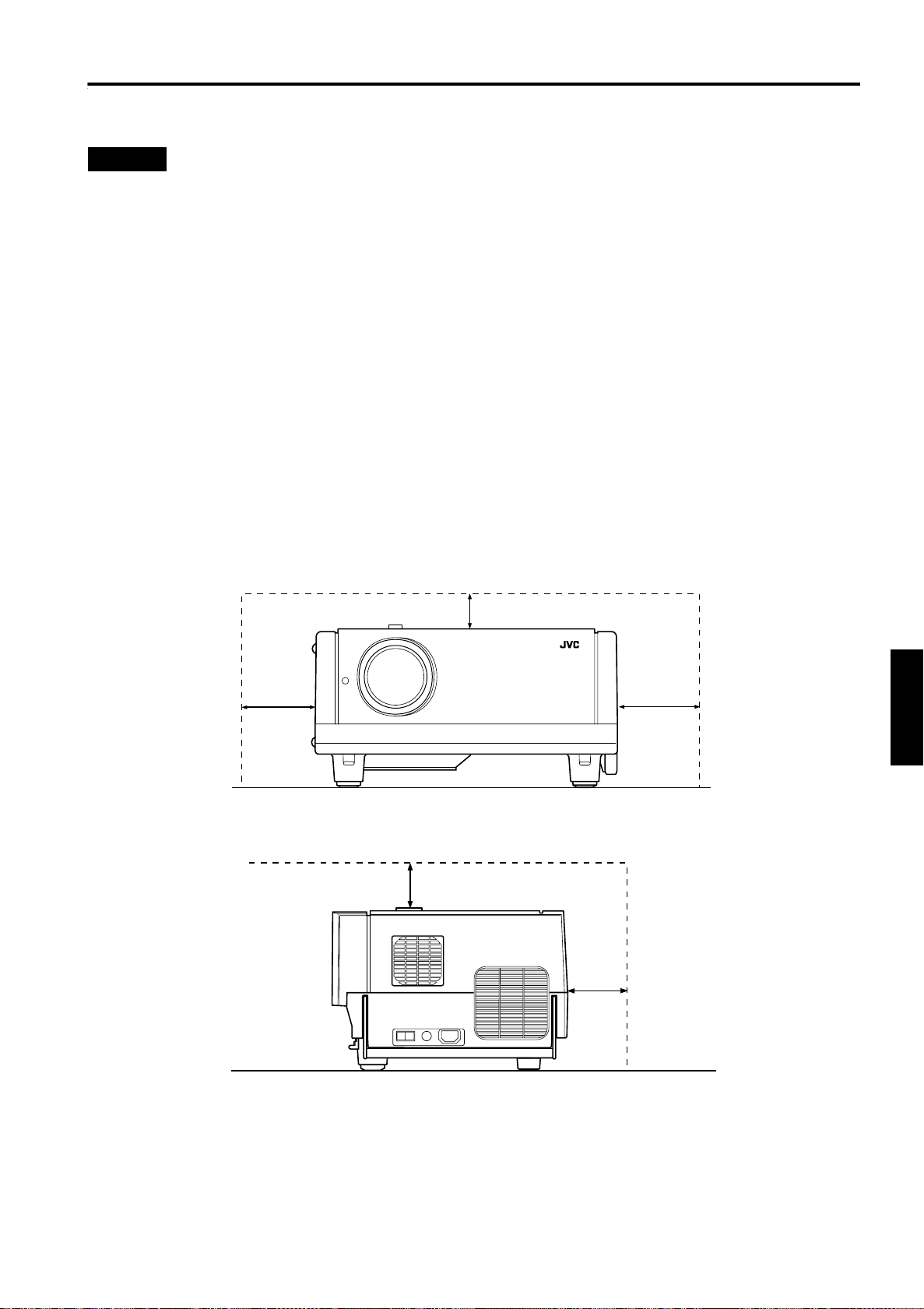
Do not use a cover which encloses the projector air-tight or blocks the exhaust vents. Allow sufficient space around the
projector. When the projector is enclosed in a space of the following dimensions, use an air conditioner so the temperature
inside becomes equal to the outside temperature.
Allowable minimum space required
200mm
300mm
600mm
ENGLISHDEUTSHFRANÇAISITALIANOESPAÑOL
300mm
200mm
15
Page 17
Installing the Projector
Adjusting the Inclination of the Projector
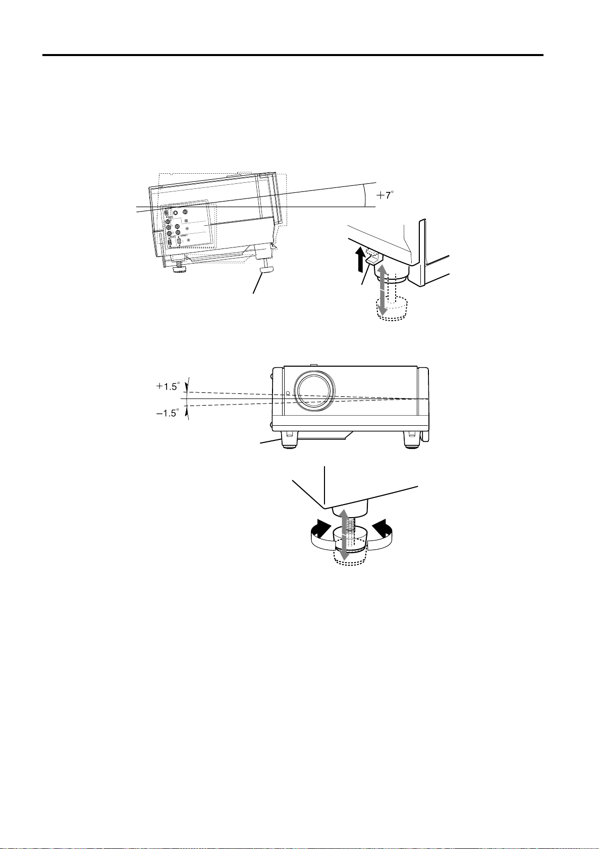
The vertical angle and the leveling of the projector can be adjusted with the adjustable feet at the bottom of the projector.
Adjusting the vertical angle of the projector
■
While pushing the levers on both sides upward, raise the projector. The adjustable feet automatically extend.
To retract the feet, push the levers and lower the projector slowly; the projector is fixed at the position
where you release the levers.
O
E
ID
V
/C
Y
IO
D
U
A
R
Y
-
/R
R
P
IO
D
U
A
C
P
G
H
Y
V
B
-Y
/B
B
P
E
T
O
M
E
R
C
2
23
-
S
R
Adjustable feet (at the front)
lever
Leveling the projector
■
Lift the projector, rotate the rear adjustable foot, and adjust the horizontal angle until the projector is level.
Adjustable foot (at the rear)
Fixing foot (at the rear)
ShortenExtend
16
Page 18
Installing the Projector
Installing the Projector against the Screen
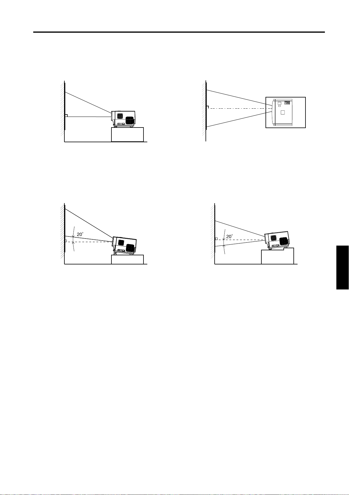
The projector should be placed so that the center line of the lens is at a right angle to the screen as shown in the following
figures.
Side view
■
■ Trapezoidal-distortion correctable maximum angle
The projector has a function to correct the trapezoidal distortion of the projected image on the screen.
To correct this distortion, use the KEYSTONE buttons on the projector. (Refer to “Removing the Trapezoidal Distortion of the
Image” on page 34.) Also, correction is possible by using the “Keystone” menu. (Refer to “Setting and Adjusting Other
Functions (OPTIONS)” on page 52.)
Correctable angle:
Top view
■
Correctable angle:
PC
MENU
VIDEO
STAND BY
OPERATE
HIDE
LAMPTEMP
PRESET
ESCAPE ENTER
KEYSTONEVOLUME
Up to approx. 20° upward from the horizontal line
Up to approx. 20° downward from the horizontal line
ENGLISHDEUTSHFRANÇAISITALIANOESPAÑOL
17
Page 19
Installing the Projector
Projection Distance and Screen Size
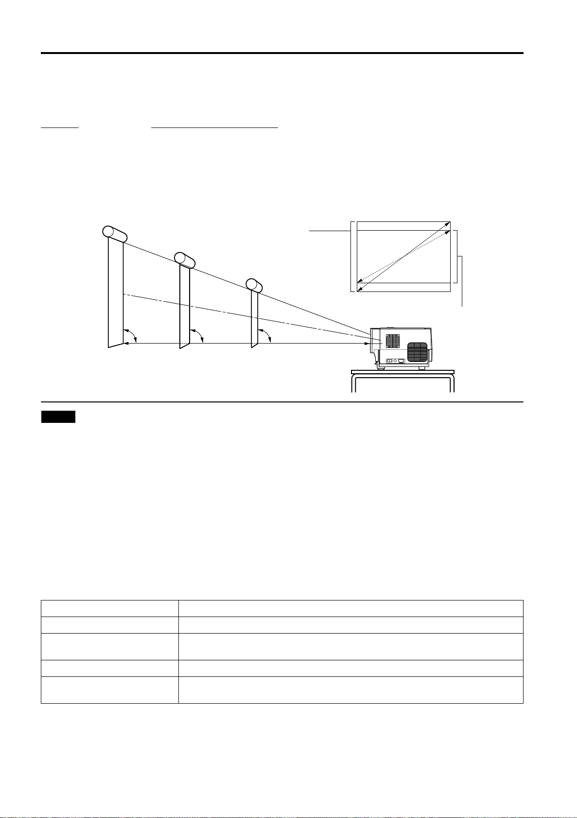
• The range of projection distances that can be focused depends on the lens unit (optional) to be used. When the aspect ratio
of the screen is 4:3, the range is as follows and you need to install the projector within this range.
Lens type
GL-M2910G 0.77 m to 4.03 m
GL-M2915SG 1.76 m to 4.50 m
GL-M2920ZG 2.77 m to 19.71 m
GL-M2930SZG 4.74 m to 29.87 m
*: The value for projection distance is a guide (reference) one. The projected image size may vary depending on the
manufacturing tolerance of the projection lens.
Screen
To move the Shift position by 50%, set the bottom edge of the projection screen so that it is at the same height as the center of the lens.
Approximate projection distance
Change of projection screen
according to aspect ratio
Screen with 4:3 aspect ratio
Screen with 16:9 aspect ratio
90˚ 90˚ 90˚
Center line of the lens
Notes
• For detailed relationship between projection distances and projection screen sizes, refer to Appendix A. The relationships for
both 4:3 and 16:9 ratios are listed there.
• When installing a screen, use a 4:3 aspect-ratio picture.
• (A 16 : 9 aspect-ratio picture is projected based on the width of the range in which a 4:3 aspect-ratio picture is projected.)
• The diagonal length of a 16:9 aspect-ratio screen is about 91.8% that of a 4:3 aspect-ratio screen. This value is only a guide
(reference).
• If sunlight or lamp light strikes the projection screen directly, the picture tends to become pale and dim. Use a curtain or
other means to shield the light.
• Set the projector horizontally on a surface that is within the range of adjustable angles (up/down adjustment angle: +7° ;
horizontal adjustment angle: ±1.5°).
• If the keystone is adjusted, the projected screen becomes smaller.
• When hanging from the ceiling, use a dedicated hanging fixture (not supplied).
■ Optional Lenses
This projector does not include a lens. You can select one of the optional lenses to adjust the projection distance. Please ask
your authorized dealer or service center to install the lens.
Lens model Function
GL-M2910G Powered focus for rear projection, short focal length (subject ratio 1:1), 0% influence.
GL-M2915SG
GL-M2920ZG Powered zoom/powered focus lens (subject ratio 2:1-3:1), 50% influence.
GL-M2930SZG
Powered focus, short focal length (subject ratio 1.5:1), powered image adjustment (2%
zoom), includes manual vertical shift function, 30%-55% influence
Powered zoom/powered focus long focal length lens (subject ratio 2.9:1-5.5:1), includes
manual vertical shift function, 30%-55% influence.
18
Page 20
Installing the Projector
Setting the Amount of Lens Shifting
When the lens unit (optional) with the lens shifting function is used, the projected screen can be shifted up and down in
position.
Notes
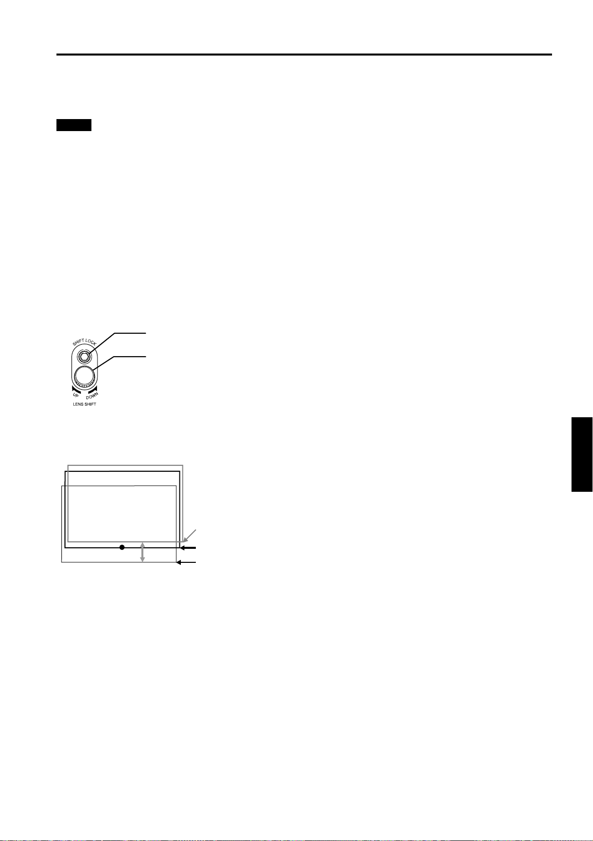
• The amount of shifting is within the range of approx. 30% to 55%.
• After finishing the lens shift setting, tighten the SHIFT LOCK fixing bolt firmly so that the lens will not move.
Turn the cap on the top of the projector to open it.
1
Loosen the SHIFT LOCK fixing bolt.
2
Use the hex. wrench supplied.
Rotate the LENS SHIFT knob to adjust the position (shift amount) of the projected
3
screen.
Rotate it to the right: The lens shifts upward.
Rotate it to the left: The lens shifts downward.
Tighten the SHIFT LOCK fixing bolt firmly.
4
Use the hex. wrench supplied.
Turn the cap to close it.
5
SHIFT LOCK fixing bolt
LENS SHIFT knob
■ Projected screen position image by amount of shift
* The projected screen position can only shift in an up-and-down direction.
The illustration shows the screen shifted sidewise for the purpose of explanation.
Approx. 55%
Approx. 50%
Approx. 30%
ENGLISHDEUTSHFRANÇAISITALIANOESPAÑOL
19
Page 21
Installing the Projector
L
A
M
P
T
E
M
P
S
T
A
N
D
B
Y
M
E
N
U
K
E
Y
S
T
O
N
E
V
O
L
U
M
E
P
R
E
S
E
T
E
S
C
A
P
E
E
N
T
E
R
O
P
E
R
AT
E
Effective Range and Distance of the Remote Control Unit
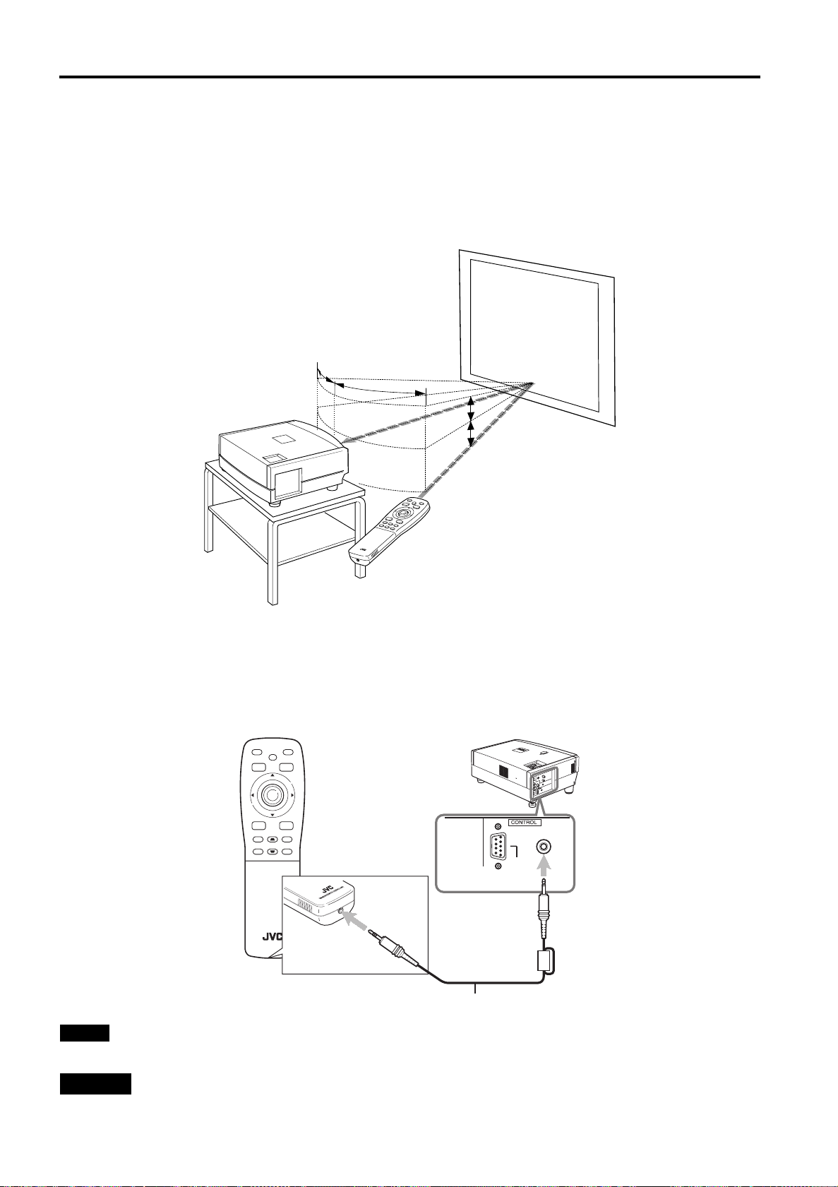
The remote control unit can be used as either a wireless remote control unit or a wired one.
Using as a wireless remote control unit
■
Aim the remote control unit toward the remote sensor on the front or the rear of the projector.
The operable distance of the remote control unit is about 10 m for direct reception. The remote control unit can be used by
having it reflected on the screen. In this case, the total distance of “A+B” should be about 10 m or less. The operable angles
of the remote control unit are 15° right and left, and 15° up and down.
Screen
15˚
15˚
Projector
A
15˚
15˚
B
Remote control unit
Using as a wired remote control unit
■
Connect the supplied remote cable between the wired terminal of the remote control unit and the REMOTE terminal on the
rear of the projector.
Connect the plug which has the remote cable core to the projector (unit) remote terminal.
Using it as a wired remote control, you do not have to worry about the operative angle of the unit, though the operative
distance is limited by the length of the remote cable (approx. 9.84 ft (approx. 3 m)).
FREEZE
HIDE
PRESET
ESCAPE
+
DIGITAL
KEYSTONE
ZOOM
–
RM-M2000 REMOTE CONTROL UNIT
OPERATE
MENU
E
VIC SELECT
VIDEO
N
T
E
R
PC
RS-232C
U
P
H
I
D
E
P
C
V
I
D
E
O
REMOTE
D
OWN
Remote cable (supplied)
Note
• When the remote control unit is used as a wired unit, its signal transmitter and the projector’s remote sensor do not work.
CAUTION
• Do not extend the remote cable. Doing so could cause a malfunction of the projector.
20
Page 22
Installing the Projector
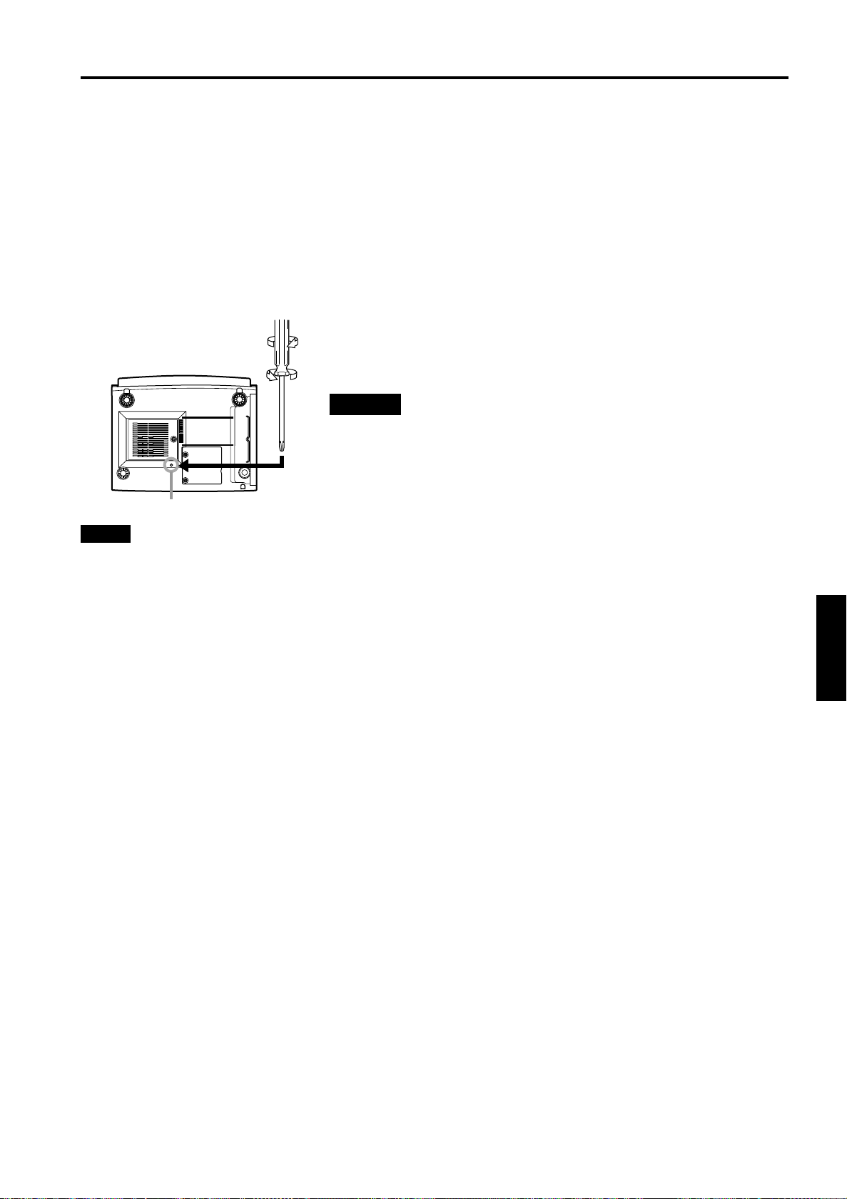
Setting the Position Selecting Screw for Ceiling Mounting
When using the projector in an upside-down, ceiling-mounted position (inverted top-to-bottom and right-to-left), the “position
selecting screw for ceiling mounting” must be turned to switch to ceiling mounting.
This will correct variance in color images (shading), which otherwise would occur in ceiling mounting.
To revert to normal desktop setting, turn the “position selecting screw for ceiling mounting” back to the initial position (factoryshipped).
When using the projector in an upside-down, ceiling-mounted position:
Turn the “position selecting screw for ceiling mounting” fully counterclockwise (until it is turning idly).
To again use the projector in a normal desktop setting:
Turn the “position selecting screw for ceiling mounting” fully clockwise (until it firmly tightens).
For normal desktop mounting:
Turn the screw clockwise.
For upside-down, ceiling-mounting:
Turn the screw counterclockwise.
CAUTIONS
•To ceiling-mount and adjust the projector, special expertise and technique ar e
necessary. Be sure to ask your dealer or a specialist to perform this work.
•To turn the “position sele cting screw for ceiling mounting”, use a Philips
screwdriver with a 30-mm or longer shank.
The screw is located in the hole shown in the illustration.
Position selecting screw for ceiling mounting
Note
• When using the projector in a ceiling-mounted position, you should reverse the projected image by changing the settings of
Right Left rev. and Top Bottom inv. menus. For details, refer to page 52. You can also change these settings without
receiving a video signal. In this case, refer to “Menu Transition Diagram in No signal Menu Mode” on page 37.
When installing (adjusting / setting) the unit
• When using “Top Bottom inv.” on the “Options” menu, reset the unit by following the procedure below.
• This reset procedure must be performed before operating the unit.
1. Change the “Top Bottom inv. ” Setting on the “Options” menu.
2. Press the OPERATE button to enter the unit into the stand-by mode.
3. Press the OPERATE button again to turn on the unit.
• Adjust the focus after projecting a picture for 30 minutes or longer.
ENGLISHDEUTSHFRANÇAISITALIANOESPAÑOL
21
Page 23
Connecting to Various Devices
Before connection, be sure to turn off the projector and connected devices.
Read the manual which comes with each device thoroughly.
Signals that Can Be Input to the Projector
The following signals can be input to the projector:
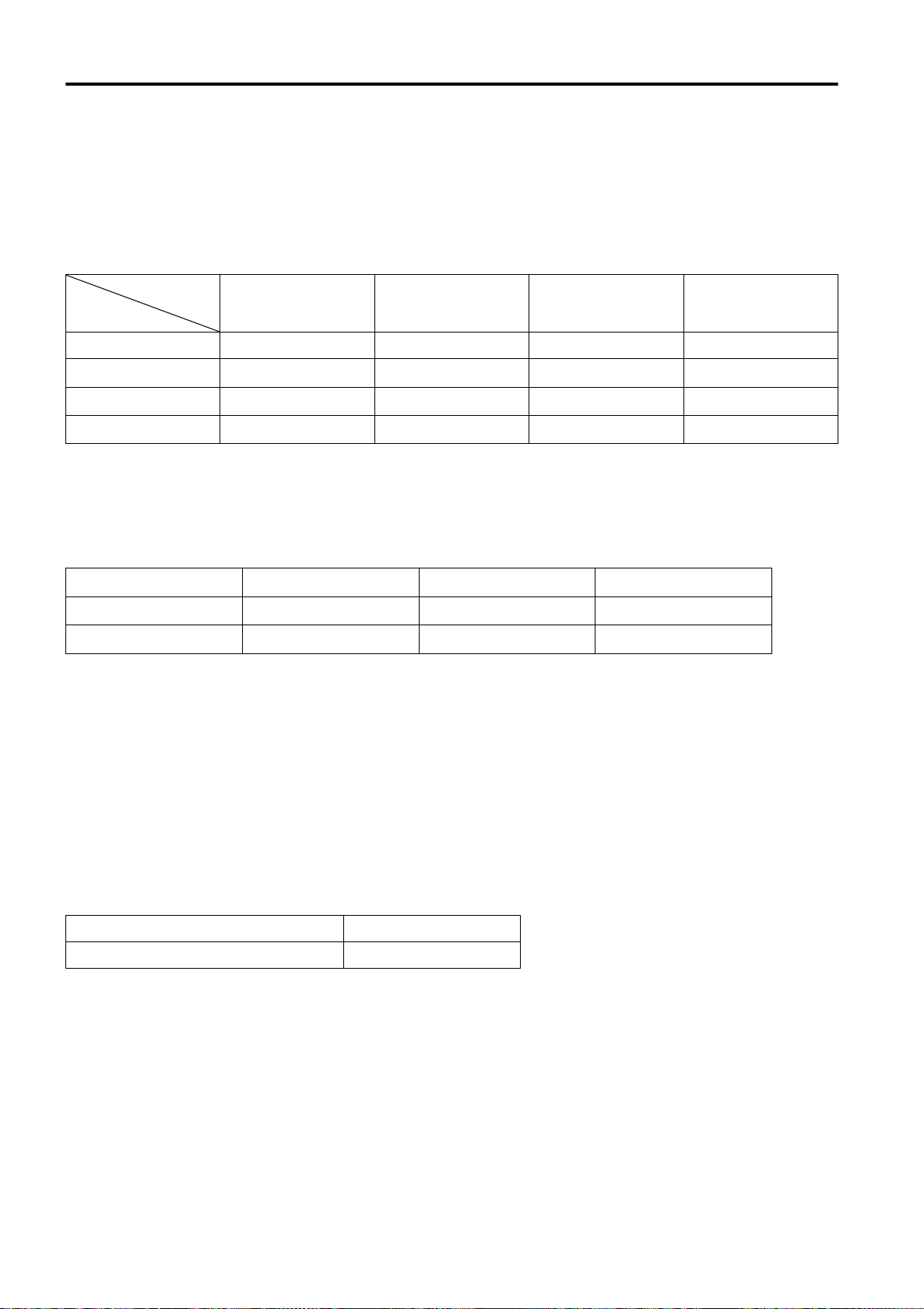
■ Video signals
(1) Response to color systems
Color systems
Input terminal
VIDEO ‡‡‡‡
Y/C ‡
/B-Y, PR/R-Y*
B
Y, P
G, B, R, H/CS, V*
3
4
*1:Responds if Y/C output is available.
*2:Signifies that component signals (“Y, P
(synchronization and video period) of each color system. The color systems are used for convenience only.
*3:To use these signals, it is required to set the “PC2 (BNC)” item in the submenu Options 1 to “YP
*4:To use these signals, it is required to set the “PC2 (BNC)” item in the submenu Options 1 to “RGB”. (Refer to page 52.)
Response to double density (*5), high-vision signals
(2)
Input terminal
S
, V*
8
9
/B-Y, PR/R-Y*
Y, P
B
G, B, R, H/C
NTSC NTSC4.43 PAL SECAM
1
‡*
2
‡*
2
*
‡
B
, PR” / “Y, B-Y, R-Y” / “G, B, R, H/CS, V”) conform to the signal timing
6
NTSC*
‡*
‡
*
2
2
NTSC*
7
‡ - - - - -
2
‡*
‡
2
*
BPR
”. (Refer to page 52.)
‡*
‡
High-vision signal
2
2
*
‡‡‡
‡‡‡
*5:Signals whose density of scanning lines/field is twice as high.
*6:Responds to signals whose horizontal scanning frequency is 31.5 kHz. NTSC can be made twice as dense by a line
doubler (separately available: recommended article). Also, possible to respond to fully-specified, decoded
wide-clear-vision signal and decoded 525P progressive signal.
*7:Responds to signals whose horizontal scanning frequency is 33.5 kHz. PAL can be made twice as dense by a line doubler
(separately available: recommended article).
BPR
*8:To use these signals, it is required to set the “PC2 (BNC)” item in the submenu Options 1 to “YP
”. (Refer to page 52.)
*9:To use these signals, it is required to set the “PC2 (BNC)” item in the submenu Options 1 to “RGB”. (Refer to page 52.)
(3) Response to DTV-format signals
DTV-format signals (480i, 480p, 720p, 1080i) can be input to the Y, P
*10:To use these signals, it is required to set the “PC2 (BNC)” item in the submenu Options 1 to “YP
/B-Y, PR/R-Y*10 input terminals.
B
BPR
”. (Refer to page 52.)
■ Computer signals
Signals with the following scanning frequencies can be input to the PC 1 or PC 2 (G, B, R, H/CS, V) terminals.
Horizontal scanning frequency 15kHz - 105kHz
Vertical scanning frequency 50Hz - 100Hz
Be sure that the computer to be used suffices the following conditions:
• The computer has the video signal output port.
Be sure that the computer has the video signal output port by reading the instruction book of the computer.
The video signal output port is generally called as “RGB port”, “monitor port”, or “video port”. If the computer-monitor hybrid
type or note type is used, it may need to prepare for an external output port. Also, there will be the type to which an external
output port cannot be installed.
• The resolution and the scanning frequencies are within the range specified in the table on page 23.
Be sure that the resolution and the scanning frequencies of the video signal are within the range. A video signal out of range
cannot be used. (Even signals out of the range could be projected. However, it may not sharp enough. On the other hand,
even some of the signals within the range may require adjustment depending on the video board used.)
When a signal other than listed in the table on page 23 is input, the image could be partially erased or an unneeded fold-over
image could appear.
Even signals in the frequency range that can be input may not be displayed normally depending on the type of the signal.
) and G on Sync signals cannot be handled depending on the devices connected.
Composite sync (C
S
22
Page 24
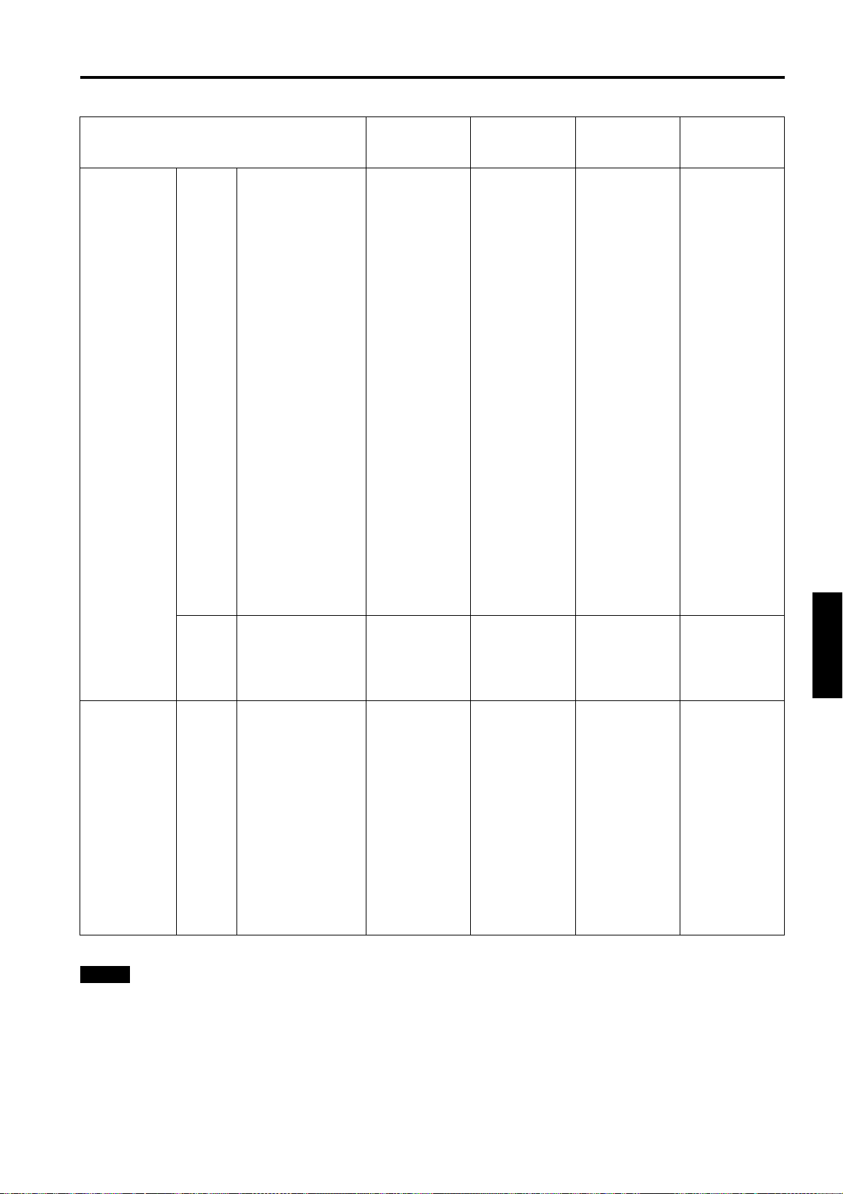
■ Allowable input signals
Connecting to Various Devices
Horizontal
Signal
PC system PC98 VESA350 640 350 37.86 84.13
PC/AT PC98 640 400 24.83 56.42
DOS/V VGA 60Hz 640 480 31.47 59.94
VGA 72Hz 640 480 37.86 72.81
VGA 75Hz 640 480 37.50 75.00
VGA 85Hz 640 480 43.27 85.01
SVGA 56Hz 800 600 35.16 56.25
SVGA 60Hz 800 600 37.88 60.32
SVGA 72Hz 800 600 48.08 72.19
SVGA 75Hz 800 600 46.88 75.00
SVGA 85Hz 800 600 53.67 85.06
XGA 43Hz 1024 768/2 35.52 43.48
XGA 60Hz 1024 768 48.36 60.00
XGA 70Hz 1024 768 56.48 70.07
XGA 75Hz 1024 768 60.02 75.03
XGA 85Hz 1024 768 68.68 85.00
SXGA 43Hz 1280 1024/2 46.43 43.44
SXGA 60Hz 1280 1024 63.98 60.02
SXGA 75Hz 1280 1024 79.98 75.03
SXGA 85Hz 1280 1024 91.15 85.02
UXGA 60Hz 1600 1200 75.00 60.00
Mac MAC13 640 480 35.00 66.67
MAC16 832 624 49.73 74.55
MAC19 1024 768 60.24 74.93
MAC21 1152 870 68.68 75.06
Video system Video HDTV (1035i) 60Hz 33.75 60.00
HDTV (1035i) 59Hz 33.72 59.94
480p 720 483 31.47 59.94
720p 60Hz 1280 720 45.00 60.00
720p 59Hz 1280 720 44.96 59.94
1080i 60Hz 1920 1080/2 33.75 60.00
1080i 59Hz 1920 1080/2 33.72 59.94
1080 24sF* 1920 1080 27.00 24.00
NTSC 15.734 60
PAL 15.625 50
SECAM 15.625 50
* : Only for DLA-M2000SCU
resolution
Hor [Pixels]
Vertical
resolution
Ver [Lines]
Horizontal
frequency
H [kHz]
Vertical
frequency
V [Hz]
ENGLISHDEUTSHFRANÇAISITALIANOESPAÑOL
Notes
• The resolution for the input signals is listed in the above table.
• Even signals in the frequency range that can be input may not be displayed normally depending on the type of the signal.
• When a signal other than listed above is input, the image could be partially erased or an unneeded fold-over image could
appear.
• Some signals other than listed above can be displayed. But they may require adjustment.
• Even some of the signals listed above may require adjustment depending on the video board used.
) and G on Sync signals cannot be handled depending on the devices connected.
• Composite sync (C
• The VGA signal of the PC system could be displayed in 480p mode of the VIDEO system. (In this case, the projector enters
video menu mode when the MENU button is pressed.)
S
23
Page 25
Connecting to Various Devices
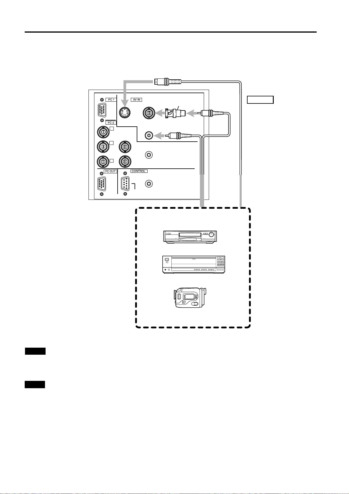
Connecting to Video Devices
Before connection, be sure to turn off both the projector and video device.
• Read thoroughly the manual that comes with each video device.
• Use the supplied AV connection cable. An AV connection cable with an S-video (Y/C) terminal is not supplied.
BNC-RCA
Y/C VIDEO
conversion plug
(accessory)
To AV IN
G
B
P
R
P
Y
R/R-Y
B/B-Y
AUDIO
PC AUDIO
H
V
REMOTE
RS-232C
AV connection cable
(accessory)
Video devices
• VCR (Video cassette recorder)
• Laser videodisc player
• Camcorder
To AUDIO
To VIDEO
To Y/C
S-video cable
(separately available)
Notes
• Connect a composite image signal output device or Y/C (S-video) image output device.
• When an image signal is input to the AV IN (VIDEO or Y/C) terminal, input the sound signal to the AUDIO terminal of the AV
IN terminals.
Memo
• When connecting a video device, use a TBC along with it, or one which has a built-in TBC.
• Use of an extension cable to connect a video device and the projector could cause video degradation.
• When a signal with much jitter is reproduced on a VCR, or special-effect playback is performed, the upper part of the image
or the image itself may be erased or distorted.
24
Page 26
Connecting to Various Devices
Connecting to Hi-Vision Devices / DVD Players
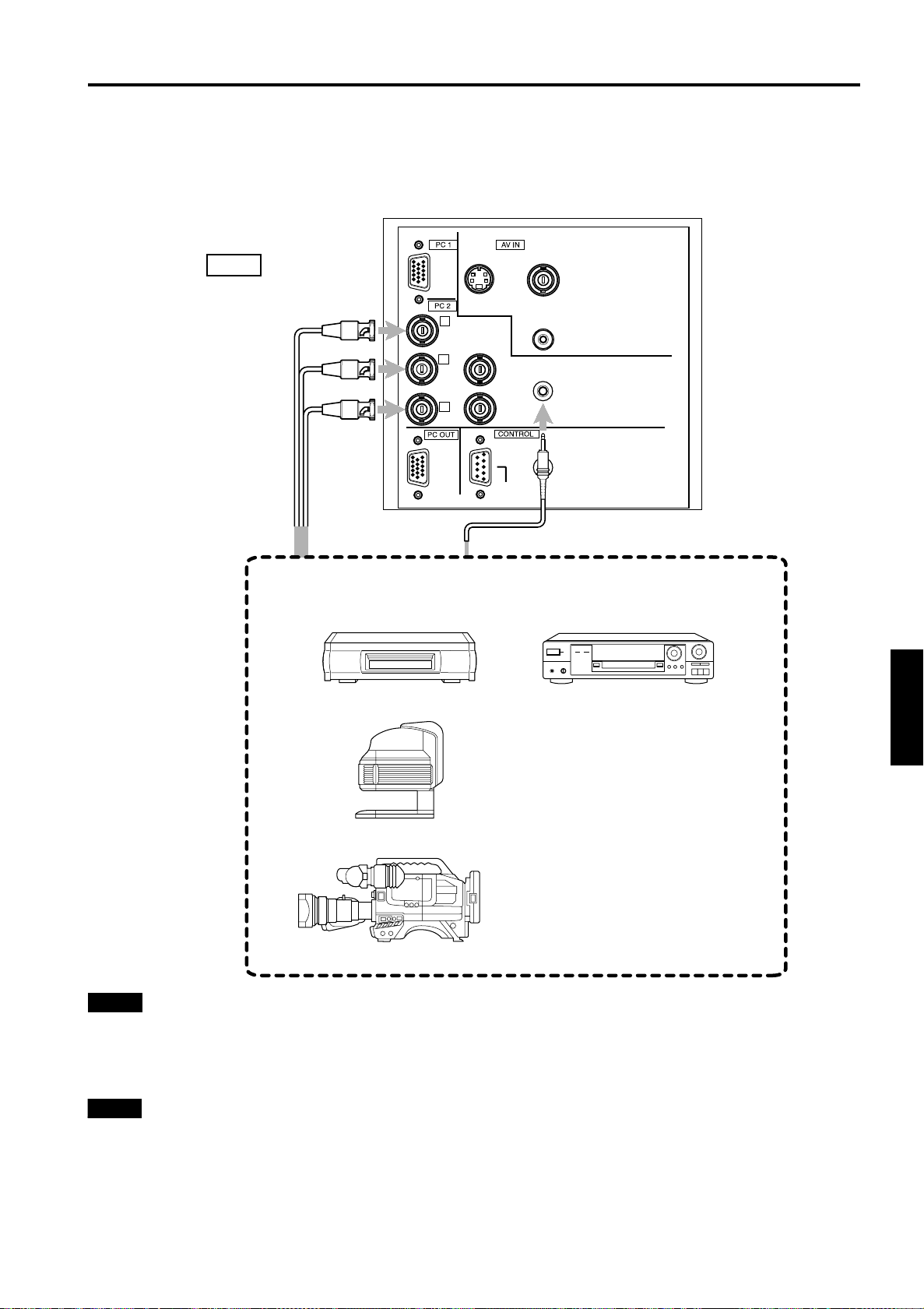
Before connection, be sure to turn off both the projector and Hi-Vision devices / DVD players.
• Read thoroughly the manual that comes with each Hi-Vision device or DVD player.
• Use separately available BNC cables and audio cables to connect Hi-Vision devices and DVD players.
To PC2
BNC cable
(separately available)
R/R-Y
To P
To Y
B/B-Y
To P
Audio cable
(separately available)
Hi-Vision devices
• W-VHS VCR
P
R
P
G
Y
B
R/R-Y
B/B-Y
Y/C VIDEO
AUDIO
PC AUDIO
H
V
REMOTE
RS-232C
To PC AUDIO
DVD player
• Text/video camera
• Hi-Vision video camera
Notes
• Connect a component signal output device or DTV-format signal output device.
• When the PC2 input terminal is used, “PC2 (BNC)” must be selected from the menu options. Refer to “Setting and Adjusting
Other Functions (OPTIONS)” on page 52.
• When the image signal is input to the PC2 input terminal, input the sound signal to the PC AUDIO terminal.
Memo
• Other devices with component signal output terminals (DVD player (NTSC), etc.) can be connected.
(*DVD: Digital Video Disc)
• DTV-format signals (480i, 480p, 720p, 1080i) can be input. For DTV-format signals which can be handled, refer to “Video
signals” on page 22.
ENGLISHDEUTSHFRANÇAISITALIANOESPAÑOL
25
Page 27
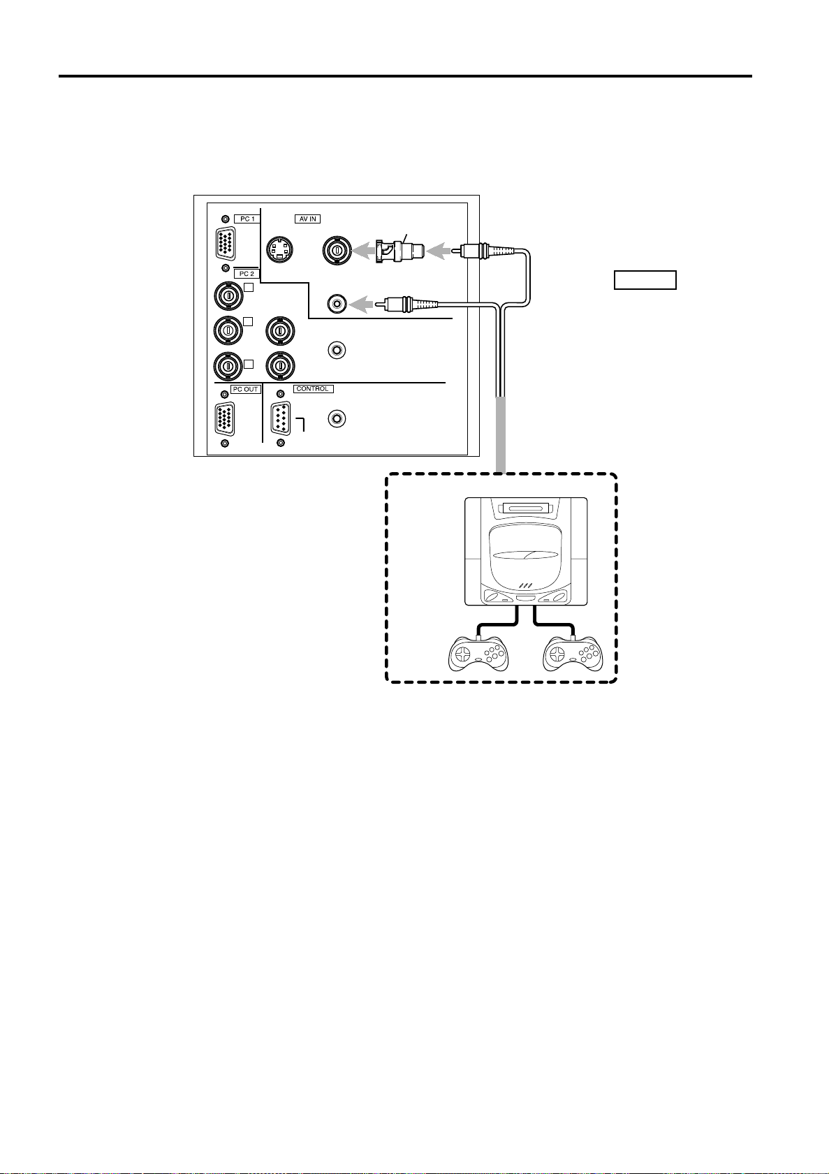
Connecting to Various Devices
Connecting to Other Devices
Before connection, be sure to turn off both the projector and other devices to be connected.
• Read thoroughly the manual that comes with the device to be connected.
• Use the supplied AV connection cable or the cable supplied with the game device.
BNC-RCA
conversion plug
Y/C VIDEO
(accessory)
To VIDEO
G
Y
B
P
R
R/R-Y
P
B/B-Y
H
V
RS-232C
AUDIO
PC AUDIO
REMOTE
To AV IN
To AUDIO
Cable supplied with the
game device, or supplied
AV connection cable
Game device, etc.
26
Page 28
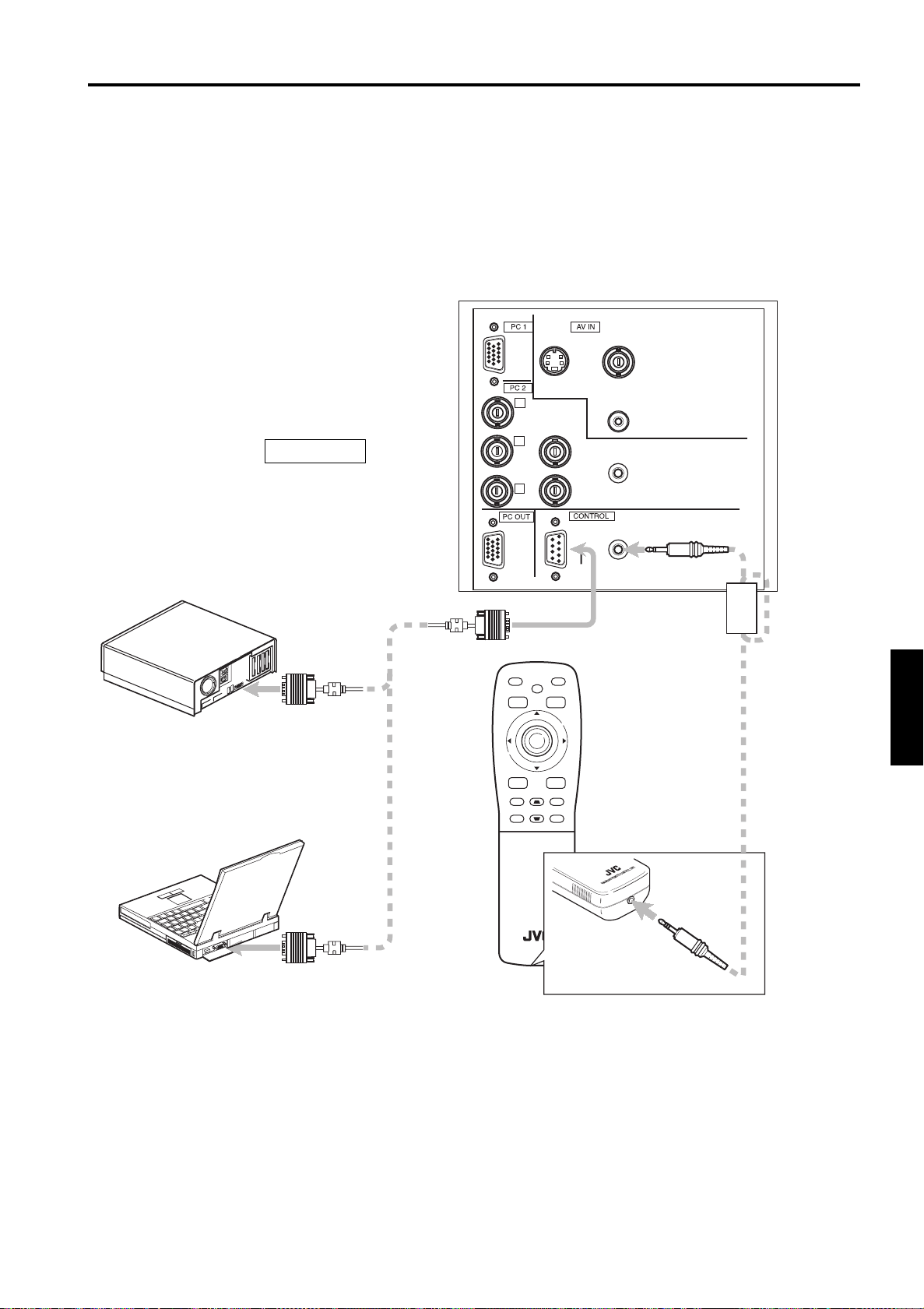
Connecting to Various Devices
Connecting to Devices which Control the Projector
Before connection, be sure to turn off both the projector and devices to be connected.
• Read thoroughly the manual that comes with each device to be connected.
• By connecting a computer to the RS-232C terminal, you can control the projector.
* Obtain connection cables as required. Use a reverse connection cable.
* For details, refer to “RS-232C external control” on page 69.
* For further details, consult your dealer or an authorized service center.
• The supplied remote control can be used as a wired remote control. Use the supplied remote cable to connect the REMOTE
terminal of the main unit with the wired remote control terminal of the remote control. (Refer to page 20.)
• Desktop type
• Note type
TO CONTROL
To RS-232C connector
RS-232C
reverse
connection
cable
(separately
available)
R
R/R-Y
P
G
Y
B
PB/B-Y
Y/C
H
V
RS-232C
VIDEO
AUDIO
PC AUDIO
REMOTE
To RS-232C connector
FREEZE
OPERATE
HIDE
MENU
PRESET
E
N
T
E
R
VIC SELECT
ESCAPE
PC
+
DIGITAL
KEYSTONE
VIDEO
ZOOM
–
RM-M2000 REMOTE CONTROL UNIT
To REMOTE terminal
Remote cable
(Supplied)
ENGLISHDEUTSHFRANÇAISITALIANOESPAÑOL
To wired remote control terminal
To RS-232C connector
27
Page 29
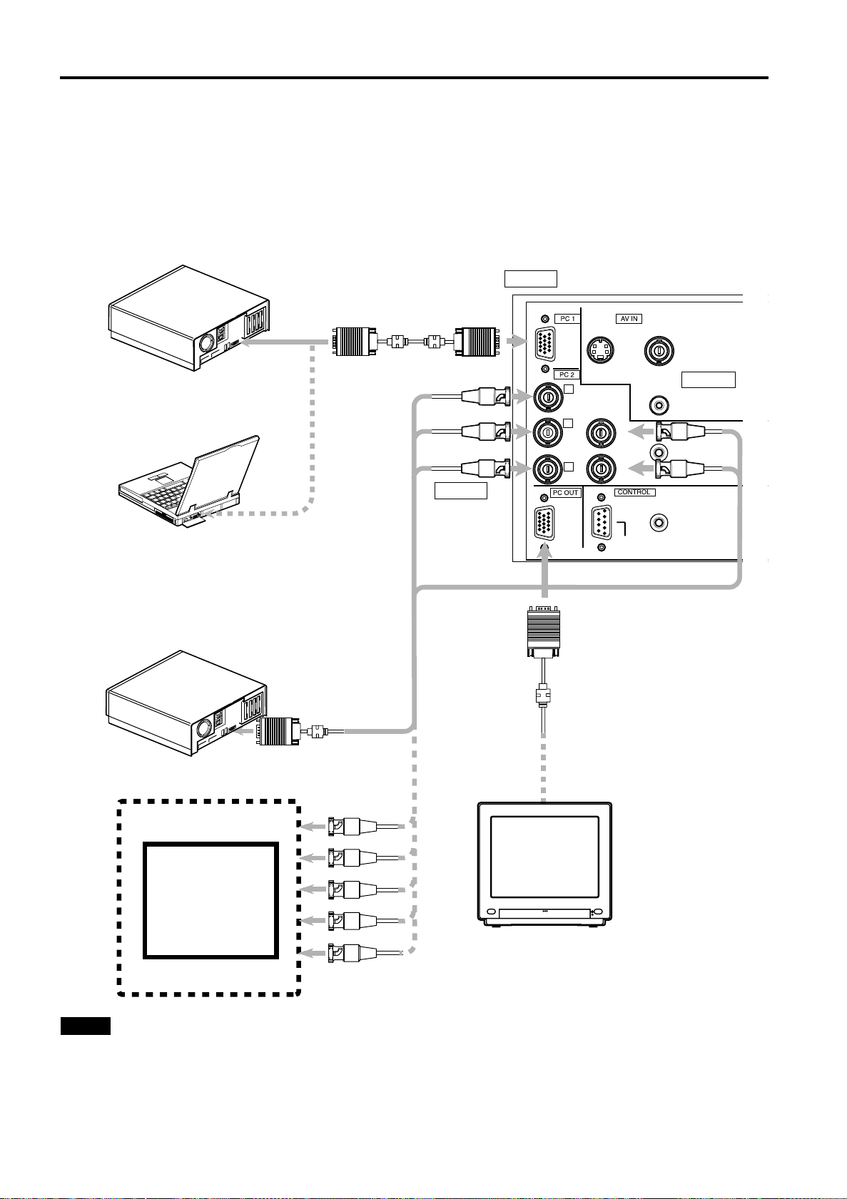
Connecting to Various Devices
Connecting to Computer Devices
Before connection, be sure to turn off both the projector and computer devices.
• Read thoroughly the manual that comes with each device.
■ Connection to an IBM PC or IBM-compatible computer
• Use the supplied personal computer connection cable. Also, prepare cables required for connecting the devices
connected.
• Desktop type
To PC 1
To monitor
connector
• Notebook type
Personal Computer
connection cable (supplied)
To PC 1
To R
To G
To B
To P C 2
R
P
G
Y
B
P
R/R-Y
B/B-Y
Y/C VIDEO
AUDIO
PC AUDIO
H
V
REMOTE
To PC 2
To H/Cs
To V
*There are some notebook types which
do not allow the computer’s LCD to work if
an external display is connected. With
such a notebook computer, the LCD
display and external display output need
to be switched.
• Desktop type
To monitor connector
• RGB output devices
Laser video disc
player, etc.
To PC 2
Separate cable
(separately
available)
To R
To G
To B
To H/Cs
To V
* When a display monitor is connected to
RS-232C
To PC OUT
Cable supplied with
the display (or
separately available)
(D-sub 3-row 15-pin)
POWER
Display monitor
the PC OUT terminal, you can view the
video from the computer on the monitor.
Notes
• When connecting an audio output terminal such as a computer sound source to the projector, connect to the PC AUDIO
terminal using the separately available audio cable.
• When the PC2 input terminal is used, “PC2 (BNC)” must be selected from the menu options. Refer to “Setting and Adjusting
Other Functions (OPTIONS)” on page 52.
28
Page 30
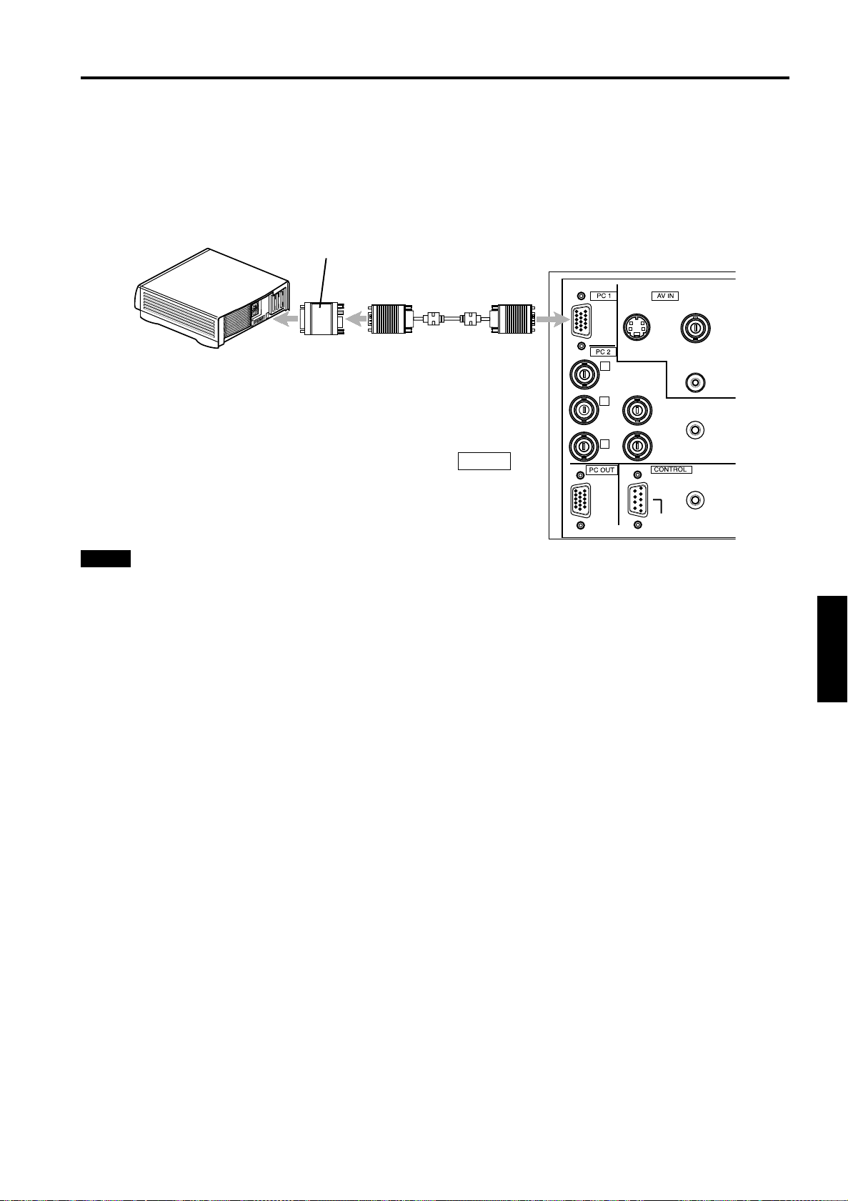
Connecting to Various Devices
Connecting to Computer Devices (Cont.)
Before connection, be sure to turn off both the projector and computer devices.
• Read thoroughly the manual that comes with each device.
■ Connection to Macintosh
• Use the supplied Personal computer connection cable and the supplied conversion adapter for Mac.
• Desktop type Conversion adapter for Mac
(supplied)
Personal computer connection cable
(supplied)
Y/C VIDEO
To monitor connector
To PC 1
To PC 1
R
P
G
Y
B
P
R/R-Y
B/B-Y
H
V
RS-232C
AUDIO
PC AUDIO
REMOTE
Notes
• When connecting an audio output terminal such as a computer sound source to the projector, connect to the PC AUDIO
terminal using the separately available audio cable.
• Other connections are the same as in the connection example for IBM PC or IBM compatible PCs.
ENGLISHDEUTSHFRANÇAISITALIANOESPAÑOL
29
Page 31
Connecting to Various Devices
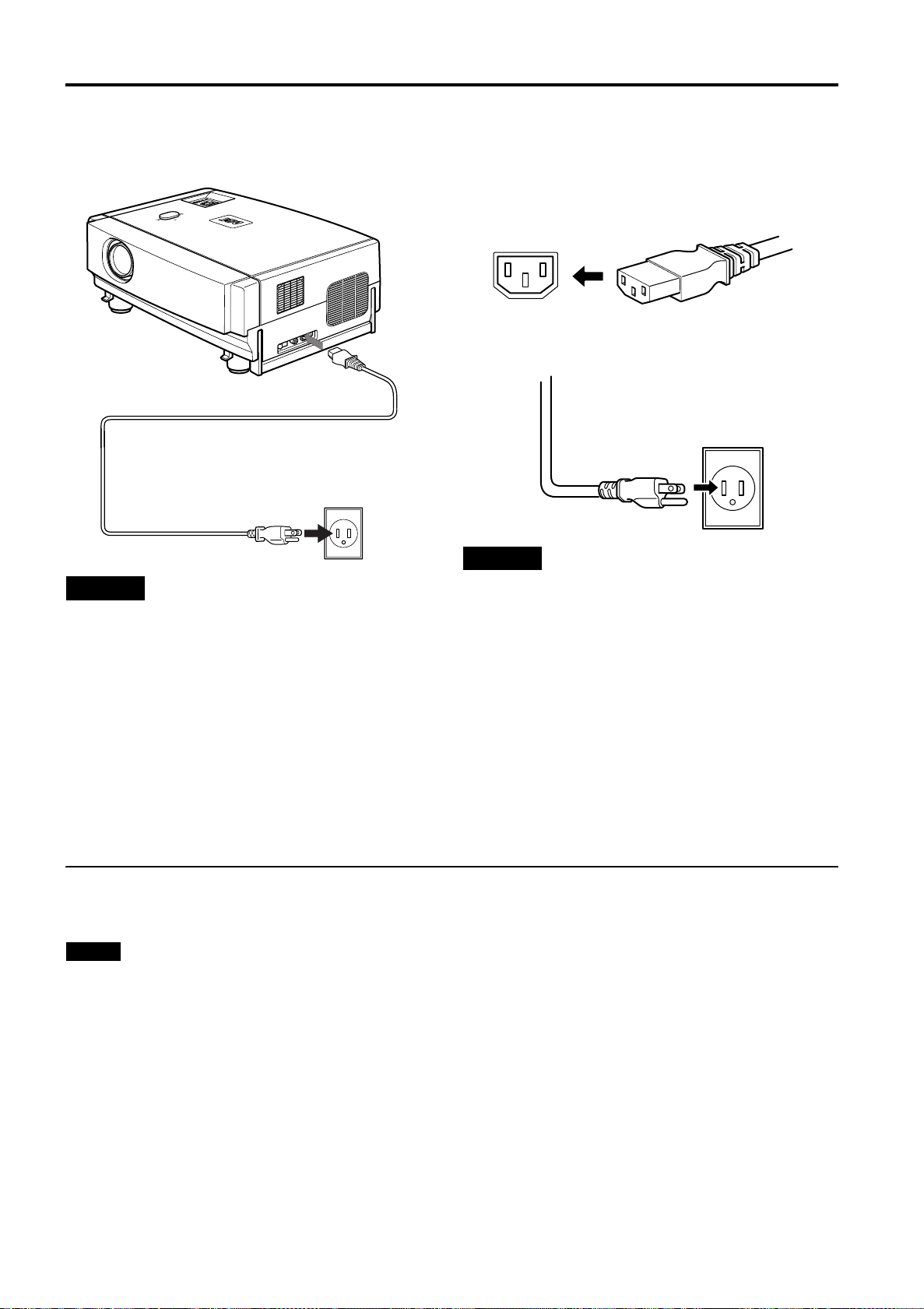
Connecting the Power Cord
After all devices have been finished being connected, connect the supplied power cord. At this time, do not yet turn on the
MAIN POWER switch.
Insert the supplied power cord into the
R
E
T
N
E
U
N
E
O
M
E
D
I
V
C
E
P
P
A
C
S
E
E
E
T
M
A
U
R
L
E
P
O
V
O
T
E
S
E
E
R
P
N
O
T
E
S
D
I
Y
P
E
H
M
K
E
T
P
M
A
L
Power cord (supplied)
1
power input terminal of the projector.
Insert the main plug of the supplied
2
power cord into a suitable wall outlet.
CAUTIONS
To prevent fire and electric shock, observe the
following:
• When you do not use devices, pull out their power cords
from wall outlets.
• Do not connect the devices with power cords other than
those supplied.
• Do not use mains voltage other than the power voltage
indicated.
• Do not scar, damage, or work on the power cords. Also, do
not put a heavy object on, heat, or stretch the power cords,
otherwise they may be damaged.
• Do not insert or pull out the plugs with a wet hand.
Removing the Lens Cap
Remove the lens cap before using the projector.
Notes
• The lens cap is supplied with the lens unit (optional). It
should be attached to the lens when the projector is not
used.
• Do not operate the projector with the lens cap attached.
Doing so can deform the lens cap because of the heat. A
metallic lens cap can get hot and cause injury.
CAUTIONS
• Do not turn on the projector without installing the lens unit
(optional). Doing so can cause the lens-hole blind cover
(black one) initially installed to be deformed by heart from
the light-source lamp.
• Since the power requirement of the projector is high, insert
the power plug directly into a wall outlet.
• Use the supplied power cord with the ferrite core only.
• Do not remove the ferrite core from the supplied power
cord; Otherwise, there may be a possibility that a harmful
interference occurs.
30
Page 32
Basic Operations
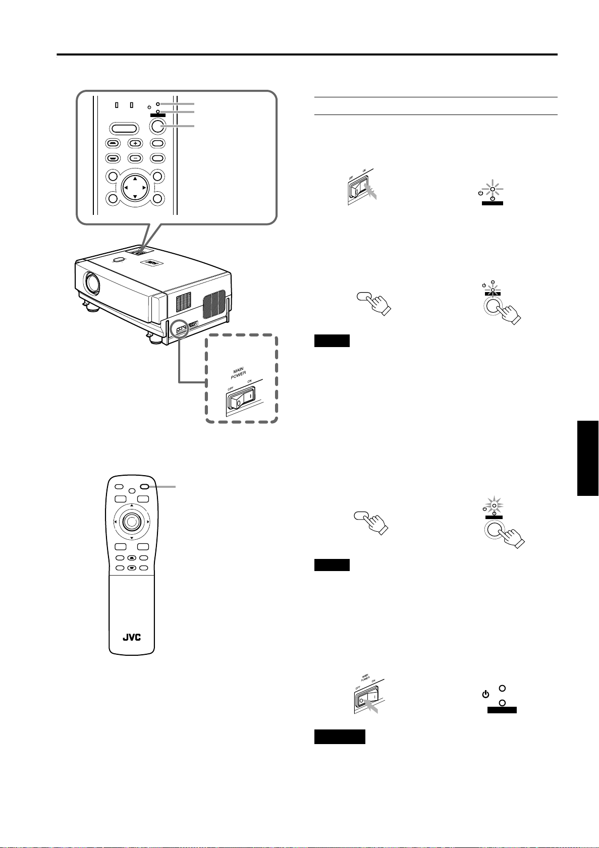
■ Projector’s buttons
LAMP TEMP
HIDE
KEYSTONE VOLUME
PRESET
ESCAPE ENTER
STAND BY
OPERATE
PC
VIDEO
MENU
ER
NT
E
NU
O
ME
E
ID
V
C
P
PE
A
SC
E
E
E
T
M
A
U
L
ER
P
O
V
O
ET
S
E
R
NE
P
O
ST
DE
I
Y
E
H
MP
K
TE
P
AM
L
STAND BY indicator
OPERATE indicator
OPERATE button
The following describes the basic procedure for normal use
of the projector.
1. Turning on the Power
Turn on the MAIN POWER switch.
1
ON [ ❙❙❙❙ ] :The main power turns on and the STAND BY
indicator comes on.
Projector’s indicator
STAND BY
OPERATE
Press the OPERATE button for one
2
second or more.
• The OPERATE indicator lights and the projected
screen slowly appears.
Remote control unit
OPERATE
or
Notes
• After the power is turned on, the image may be jumbled for a
few seconds, but this is not a malfunction.
• After the indicator comes on, it can take a minute or so for
the lamp to warm up and operate consistently.
Projector
STAND BY
OPERATE
■ Remote control unit
FREEZE
OPERATE
HIDE
MENU
PRESET
E
N
T
E
R
VIC SELECT
ESCAPE
PC
+
DIGITAL
KEYSTONE
VIDEO
ZOOM
–
+
T
U
FOCUS
ZOOM
SHIFT
SHUTER
W
D
+
QUICK
ALIGN.
–
RM-M2000 REMOTE CONTROL UNIT
VOLUME
–
+
–
OPERATE button
■ Turning off the Power
Press the OPERATE button for one
1
second or more.
• The STAND BY indicator changes to blinking, and the
projector goes into cool-down mode. The cool-down
mode will continue for approximately 120 seconds.
Remote control unit
OPERATE
Projector (Blinking)
STAND BY
OPERATE
Note
• The OPERATE button will not work for approximately 1
minute from when the light-source lamp is turned on. Use
the button after approximately 1 minute.
Turn off the MAIN POWER switch after the
2
STAND BY indicator changes to steady on.
OFF [‡‡‡‡] :The MAIN POWER switch turns off and the
STAND BY indicator goes off.
Projector
STAND BY
OPERATE
ENGLISHDEUTSHFRANÇAISITALIANOESPAÑOL
CAUTION
• Do not turn off the MAIN POWER switch during cool-down
mode (the STAND BY indicator blinking). Turn it off after
the STAND BY indicator becomes on (stand-by mode).
31
Page 33
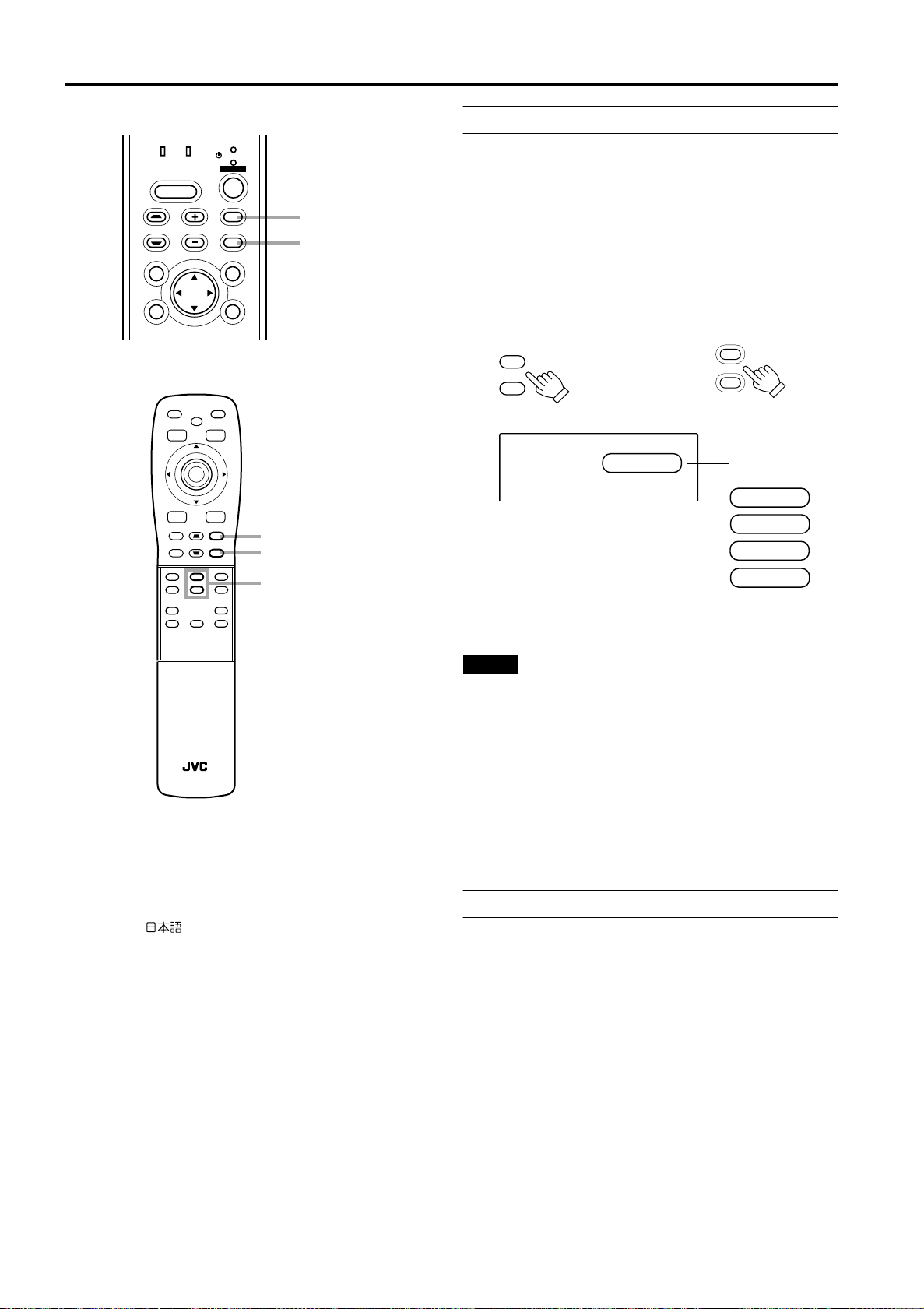
Basic Operations
■ Projector’s buttons
LAMP TEMP
HIDE
KEYSTONE VOLUME
PRESET
ESCAPE ENTER
STAND BY
OPERATE
PC
VIDEO
MENU
■ Remote control unit
FREEZE
OPERATE
HIDE
MENU
PRESET
E
N
T
E
R
VIC SELECT
ESCAPE
PC
+
DIGITAL
KEYSTONE
VIDEO
ZOOM
–
+
T
U
FOCUS
ZOOM
SHIFT
D
+
SHUTTER
–
QUICK
ALIGN.
–
W
+
VOLUME
–
PC button
VIDEO button
PC button
VIDEO button
ZOOM button
2. Select the Input source to be Projected
Press the VIDEO button or the PC button to switch the
input.
• Each time you press either button, the selected input
changes as follows. The selected name appears on the top
right of the image on the screen for five seconds. (Called
line display.)
When you press the VIDEO button:
Y/C l VIDEO
When you press the PC button:
PC1 l PC2
Remote control unit Projector
PC
VIDEO
[Screen display]
VIDEO
QUICK ALIGNMENT
* To show the line display (Y/C, VIDEO, PC1, or PC2) or not
is selectable by the menu. Refer to “Setting and Adjusting
Other Functions (OPTIONS)” on page 52.
PC
VIDEO
Line Display
PC 1
PC 2
Y/C
VIDEO
RM-M2000 REMOTE CONTROL UNIT
■ Language display
The display languages of the menus, direct buttons
(DIGITAL ZOOM, KEYSTONE, VOLUME, etc) and
messages is set to “ENGLISH” when the projector is bought.
The display language can be selected from the following 6
languages: “ (Japanese)”, “English (English)”,
“Deutsch (German)”, “Español (Spanish)”, “Italiano (Italian)”
and “Français (French)”. (Refer to page 45.) However, some
words (VIDEO, NTSC, Quick Alignment, etc) are only
displayed in English.
Notes
• When the AV IN (Y/C or VIDEO input) terminal input signal
source is switched with the VIDEO button, it is necessary to
reconnect the audio cable to the active device since the
projector has only a single AUDIO input terminal.
• When the PC1 or PC2 input terminal signal source is
switched with the PC button, it is necessary to reconnect
the audio cable to the active device since the projector has
only a single PC AUDIO input terminal.
• When no image signal is input to the selected input
terminal, the message “No Input” is displayed on the
screen. (Refer to page 64.)
• When the PC2 input terminal is used, “PC2 (BNC)” must be
selected from the menu options. (Refer to page 52.)
3. Adjust the Screen Size (Zooming)
How to adjust the projected screen size differs depending on
the lens unit (optional) you are using.
GL-M2910G (without zooming function):
The projected screen size cannot be changed.
GL-M2915SG/GL-M2920ZG/GL-M2930SZG (with
zooming function):
Adjust the projected screen size with the following buttons on
the remote control unit.
32
Page 34
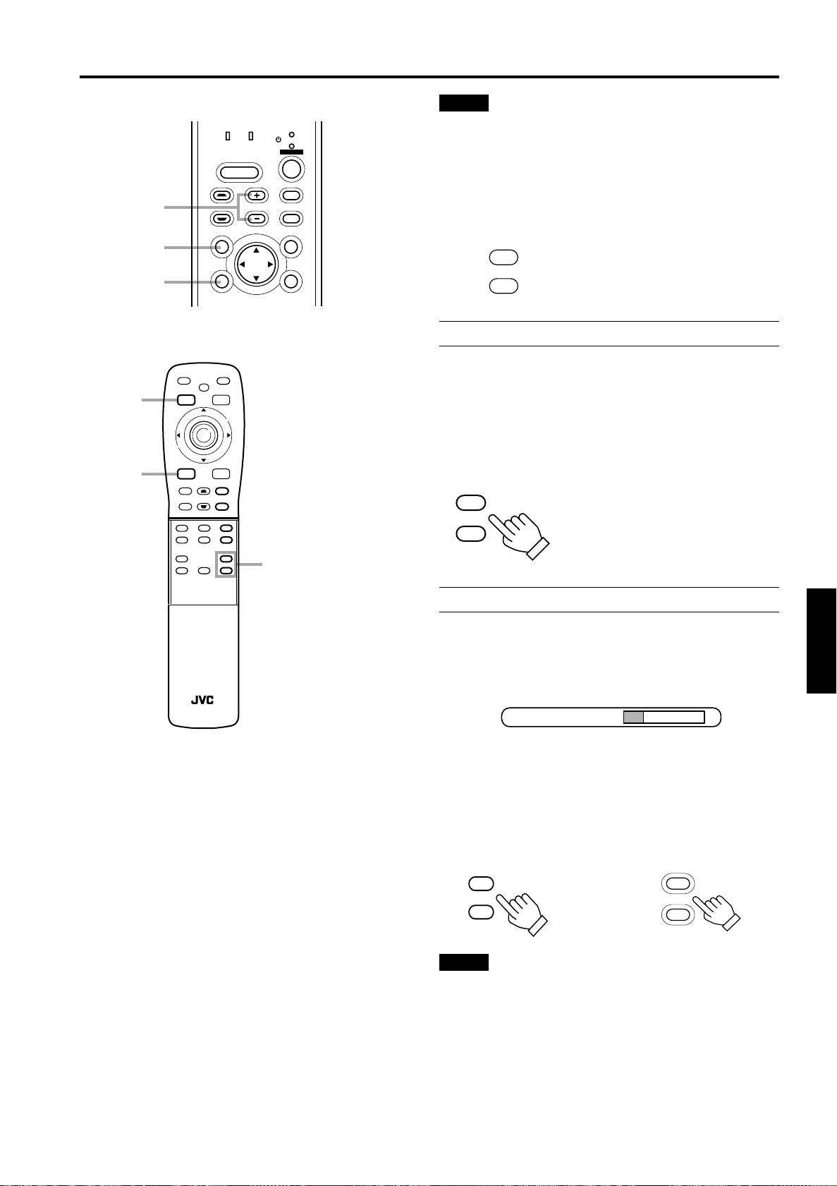
Basic Operations
■ Projector’s buttons
LAMP TEMP
HIDE
VOLUME+/-
KEYSTONE VOLUME
button
PRESET
PRESET
button
ESCAPE
button
ESCAPE ENTER
■ Remote control unit
FREEZE
OPERATE
HIDE
PRESET
SHIFT
ESCAPE
+
DIGITAL
ZOOM
–
U
D
+
–
KEYSTONE
ZOOM
W
QUICK
ALIGN.
MENU
E
N
T
E
R
VIC SELECT
PC
VIDEO
+
T
FOCUS
–
+
VOLUME
–
PRESET
button
ESCAPE
button
SHUTTER
STAND BY
OPERATE
PC
VIDEO
MENU
VOLUME+/button
Note
• The function of GL-M2915SG is to adjust the view angle
zooming by 2%. (For fine view angle adjustment)
To enlarge the projected screen size
Press the ZOOM W (Wide) button.
To reduce the screen size
Press the ZOOM T (Tele) button.
Remote control unit
T
ZOOM
W
4. Adjust Focus
Adjust focus with the following buttons on the remote control
unit.
To focus on farther points
Press the FOCUS + button.
To focus on nearer points
Press the FOCUS – button.
Remote control unit
+
FOCUS
–
RM-M2000 REMOTE CONTROL UNIT
5. Adjusting Sound Volume
Adjust sound volume with the VOLUME +/– buttons. When
the VOLUME + or – button is pressed, “Audio-Vol” appears
on the screen together with the level bar and set value (0 to
50). When “15 sec.” is displayed in the menu, “Audio-Vol” will
appear in approximately 15 seconds.
Audio - Vol 12
When you press the VOLUME + button:
The sound volume becomes higher. (0 → 50)
When you press the VOLUME – button:
The sound volume becomes lower. (50 → 0)
* When the volume is set to 0, no sound will be heard from
the built-in speaker.
Remote control unit
+
VOLUME
–
Notes
• When “Audio-Vol” is displayed on the screen, pressing the
PRESET button resets the set value to “0”.
• Press the ESCAPE button to immediately remove the
volume display.
Projector
+
VOLUME
–
ENGLISHDEUTSHFRANÇAISITALIANOESPAÑOL
33
Page 35
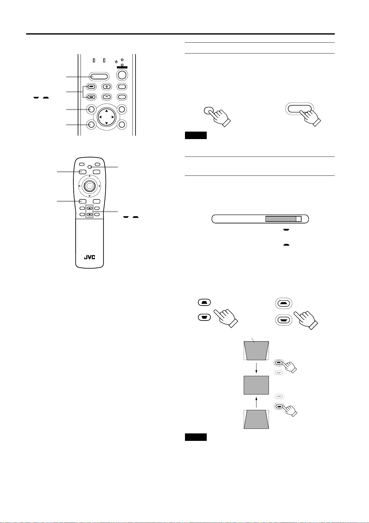
Basic Operations
■ Projector’s buttons
LAMP TEMP
HIDE
HIDE
button
KEYSTONE
/button
KEYSTONE VOLUME
PRESET
PRESET
button
ESCAPE
button
ESCAPE ENTER
■ Remote control unit
FREEZE
OPERATE
HIDE
PRESET
ESCAPE
+
DIGITAL
KEYSTONE
ZOOM
–
T
U
ZOOM
SHIFT
W
D
+
QUICK
SHUTER
ALIGN.
–
RM-M2000 REMOTE CONTROL UNIT
MENU
E
VIC SELECT
VIDEO
N
T
PC
FOCUS
VOLUME
E
R
+
–
+
–
PRESET
button
ESCAPE
button
STAND BY
OPERATE
PC
VIDEO
MENU
HIDE
button
KEYSTONE
/button
Turning off Image and Sound (HIDE)
Video image and audio sound can be temporarily turned off.
Press the HIDE button once:
Video image and audio sound instantly turn off.
Press the HIDE button again:
Video image and audio sound come on again.
Remote control unit Projector
HIDE
Note
• When the projected image input is changed, the HIDE
function is canceled and the image and sound return.
HIDE
Removing the Trapezoidal Distortion of
the Image
If the image projected on the screen is distorted in trapezoid
form, correct it with the KEYSTONE buttons on the projector.
When the KEYSTONE button is pressed, “Keystone”
appears on the screen together with the level bar and set
value (–80 to 128). When “15 sec.” is displayed in the menu,
“Keystone” will appear in approximately 15 seconds.
Keystone 123
When you press the KEYSTONE button:
The trapezoid form is corrected as shown in the figure.
When you press the KEYSTONE button:
The top bottom inverted trapezoid form is corrected as
shown in the figure.
* To cancel correction and restore the original screen, press
the PRESET button. (Adjusted value:0)
* Press the ESCAPE button to immediately remove the
keystone display.
Remote control unit Projector
KEYSTONE
KEYSTONE
Projected image with trapezoidal distortion
KEYSTONE
KEYSTONE
Notes
• The trapezoidal distortion (keystone) can be adjusted from the
option menu. (Refer to
page 52
.)
• The range of the trapezoidal distortion adjustment is
approximately 20° in the vertical direction.
• Interference patterns may appear on the screen when
adjusting the keystone. This is not a malfunction.
• Depending on the type of signal, some noise may appear in
the picture when the keystone is adjusted.
This is not a malfunction.
34
Page 36
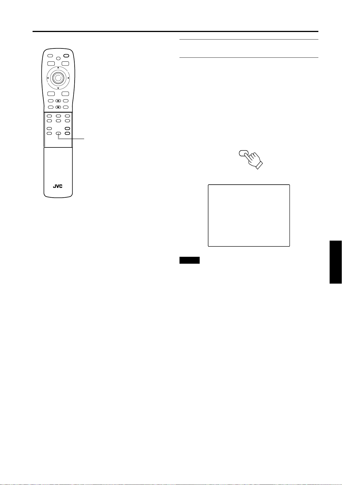
Basic Operations
■ Remote control unit
FREEZE
OPERATE
HIDE
PRESET
MENU
E
N
T
E
R
VIC SELECT
ESCAPE
PC
+
DIGITAL
KEYSTONE
VIDEO
ZOOM
–
+
T
U
FOCUS
ZOOM
SHIFT
D
+
SHUTTER
–
RM-M2000 REMOTE CONTROL UNIT
QUICK
ALIGN.
–
W
+
VOLUME
–
QUICK ALIGN. button
Quick Alignment Function
(QUICK ALIGN.)
The Quick Alignment function automatically adjusts (sets)
the screen settings of the image input from the PC1 or PC2
input terminals. This can only be performed from the remote
control.
While projecting an image on the screen, press the QUICK
ALIGN. button on the remote control.
Quick alignment is conducted to obtain best image.
* During the automatic alignment, “Quick Alignment” appears
on the screen, and then disappears when the alignment is
completed.
Remote control unit
QUICK
ALIGN.
[Screen display]
Quick Alignment
Notes
• This only works for the signals input from the PC1 or PC2 input
terminals. It does not work for the signals input from the AV IN
terminal (VIDEO or Y/C input terminal).
• The quick alignment function is used to automatically adjust
the “Horizontal and vertical position”, “Phase” and
“Tracking” of the projected image.
• When using the quick alignment function to automatically
adjust the image, use a bright, still-picture. It may not
function correctly on a dark or motion picture. If the results
obtained with the quick alignment function are not
satisfactory, manually adjust the “Horizontal and vertical
position”, “Phase” and “Tracking” of the projected image.
ENGLISHDEUTSHFRANÇAISITALIANOESPAÑOL
35
Page 37
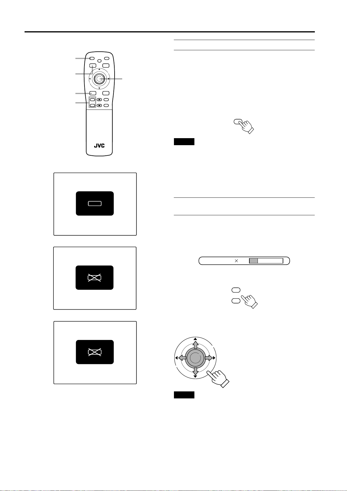
Basic Operations
■ Remote control unit
FREEZE
button
PRESET
button
ESCAPE
button
DIGITAL ZOOM
+/-button
FREEZE message
FREEZE inhibit message
FREEZE
PRESET
ESCAPE
+
DIGITAL
ZOOM
–
U
SHIFT
D
+
SHUTER
–
RM-M2000 REMOTE CONTROL UNIT
FREEZE
HIDE
KEYSTONE
ZOOM
W
QUICK
ALIGN.
Displaying a Still Picture (FREEZE)
OPERATE
MENU
E
N
T
E
R
Cursor
(5/∞/2/3)/
VIC SELECT
PC
VIDEO
T
FOCUS
VOLUME
+
–
+
–
ENTER button
While projecting an image, a still picture is obtained at any
time by using the FREEZE button on the remote control.
When you press the FREEZE button:
“FREEZE” appears on the screen for a few seconds and
then the still picture is shown on the screen. Refer to the
FREEZE message shown on the left of this page.
* To forcibly clear “FREEZE”, press the ESCAPE button.
When you press the FREEZE button again.
The original image resumes.
Remote control unit
Notes
• During freezing, the picture sent from the signal source is lost.
• If any of the inoperative buttons (“MENU”, “QUICK ALIGN.”,
“KEYSTONE”) are pressed while displaying a still picture,
“FREEZE” is displayed on the screen.
• This function will not work with some signal sources
(UXGA, etc). In this case, the FREEZE inhibit message
appears for a few seconds, as shown on the left. To forcibly
clear this message, press the ESCAPE button.
FREEZE
Zooming a Part of the Image (DIGITAL
ZOOM +/–)
A part of the image being projected can be digitally magnified up
to four times. When the DIGITAL ZOOM + or – button is
pressed, “Digital zoom” appears on the screen together with the
level bar and magnifying power (
2.5, ×3.2, ×4.0).
×
When “15 sec.” is displayed in the menu,
“Digital zoom” will appear in approximately 15 seconds.
1.0, ×1.2, ×1.4, ×1.6, ×2.0,
×
FREEZE
DIGITAL ZOOM inhibit message
D.ZOOM
Digital zoom 1.2
• To zoom up or zoom down, press the DIGITAL ZOOM + or
– button on the remote control.
Remote control unit
+
DIGITAL
ZOOM
–
Moving the zoomed image:
While “Digital zoom” appears on the screen, you can move
the zoomed image with the cursor (5/∞/2/3)/ENTER button
on the remote control.
E
N
T
E
R
Notes
• This function will not work with some signal sources
(UXGA, etc). In this case, the DIGITAL ZOOM inhibit
message appears for a few seconds, as shown on the left.
To forcibly clear this message, press the ESCAPE button.
• The quality of the zoomed image reduces in comparison
with the original one.
• To return to the original size (
press the PRESET button while “Digital zoom” is displayed
on the screen.
5: Upper part of the image will be
displayed.
∞: Lower part of the image will be
displayed.
: Left side part of the image will
2
be displayed.
3: Right side part of the image
will be displayed.
1.0) and original position,
×
36
Page 38
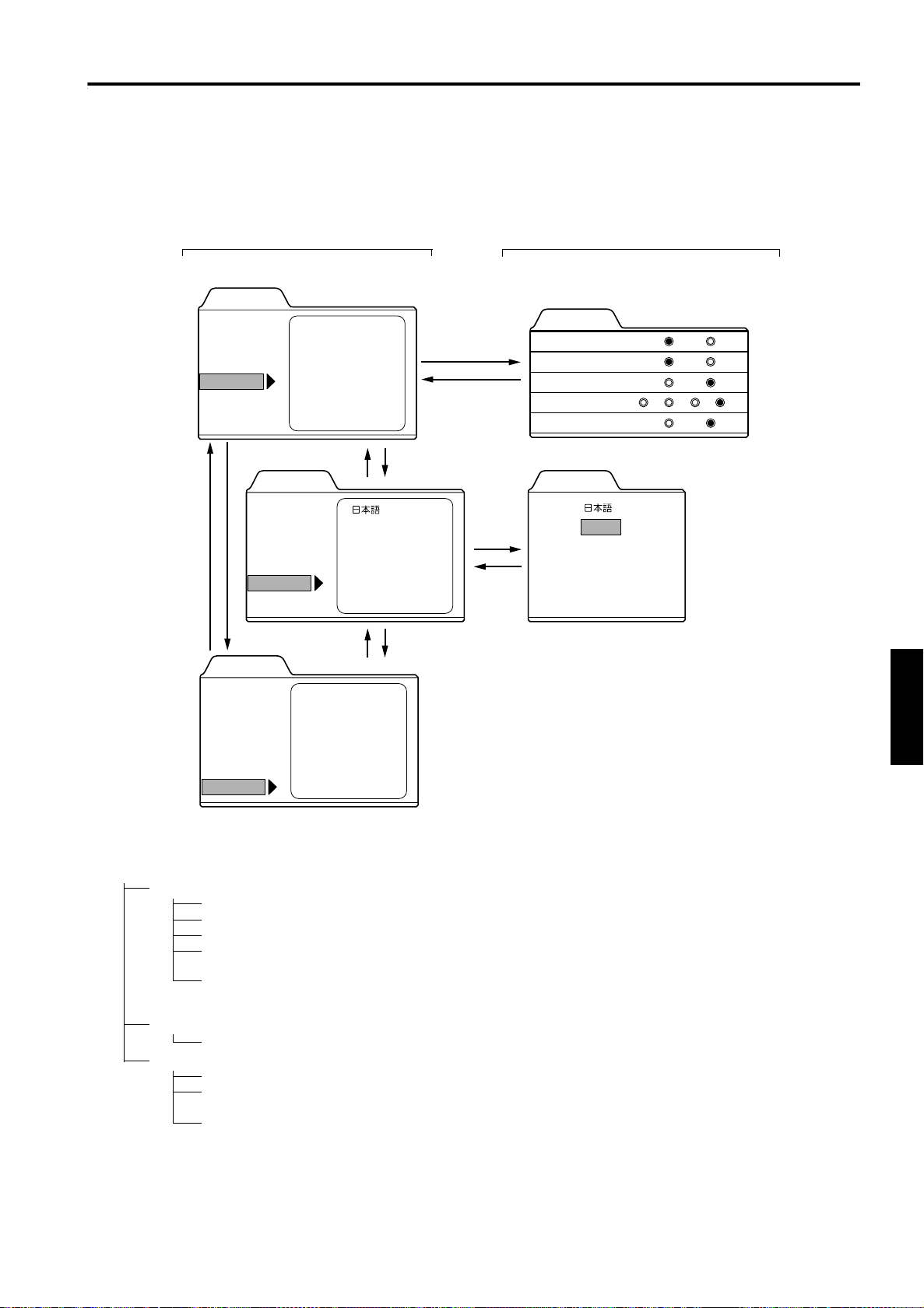
Menu Operations
You can adjust picture quality, set functions, get information on the input video signal, etc. using the menus. From the
following menu transition diagrams, you can see the overall menus and basic button operation in menu mode. Note that there
are three menu modes, No signal menu mode, video menu mode and PC menu mode. When the MENU button is pressed,
the projector enters one of these modes by judging the input signal being received.
■ Menu Transition Diagram in No signal Menu Mode
This is displayed if there is no signal from the selected input terminal.
Main menu in No signal Menu Mode Submenus in No signal Menu Mode
Press 5/∞ to select an item.
Menu
Right Left rev.
Top Bottom inv.
Options
Language
Information
RS-232C
Sleep time
PC2 (BNC)
5
Menu
Options
Language
Information
∞
Menu
Input
Switcher
5
English
Deutsch
Español
Italiano
Français
5
PC1
CH.0
∞
∞
3 or ENTER
ESCAPE
3 or
ENTER
ESCAPE
Press 5/∞ to select an item.
Press 2/3 to set the value.
Options
Right Left rev.
Top Bottom inv.
RS-232C [bps]
Sleep time [min]
PC2 (BNC)
OFF
OFF
9600
15 30 60 OFF
RGB YPBPR
Press 5/∞ to select an item.
Language
English
Deutsch
Español
Italiano
Français
ON
ON
19200
Options
Language
Information
Lamp time
123 h
■ Quick Reference Guide for No signal Menu Mode
Main Menu in No signal Menu Mode
Options
Language Language for on-screen display.
Information
Right Left rev.: OFF* / ON (Select for upside-down hanging on the ceiling.)
Top Bottom inv.: OFF* / ON (Select for upside-down hanging on the ceiling.)
RS-232C [bps]: Selectable baud rate (transmission speed). 9600 / 19200*
Sleep time [min:] Selectable sleep times. If no-signal condition continues for the period of selected time (Unit:
Minutes), the projector enters the stand-by mode. 15 / 30 / 60 / OFF*
PC2 (BNC): RGB* or YP
BPR
. Set to RGB when a computer device with analog RGB, V, H/Cs signals is
connected to the PC2 terminals. Set to YP
or DTV-format signals (Y, P
B
, PR) are connected to the PC2 terminals.
Japanese / English* / German / Spanish / Italian / French
Input: Shows the terminal name selected by the VIDEO or PC button. (Y/C, VIDEO, or PC2)
Switcher: Has no meaning. This display currently has no meaning. (“CH.0” is usually displayed to indicate
that it is not being used.)
Lamp time: Accumulated used hours of the light-source lamp.
BPR
when a device with component signals (Y, B-Y, R-Y)
ENGLISHDEUTSHFRANÇAISITALIANOESPAÑOL
37
Page 39
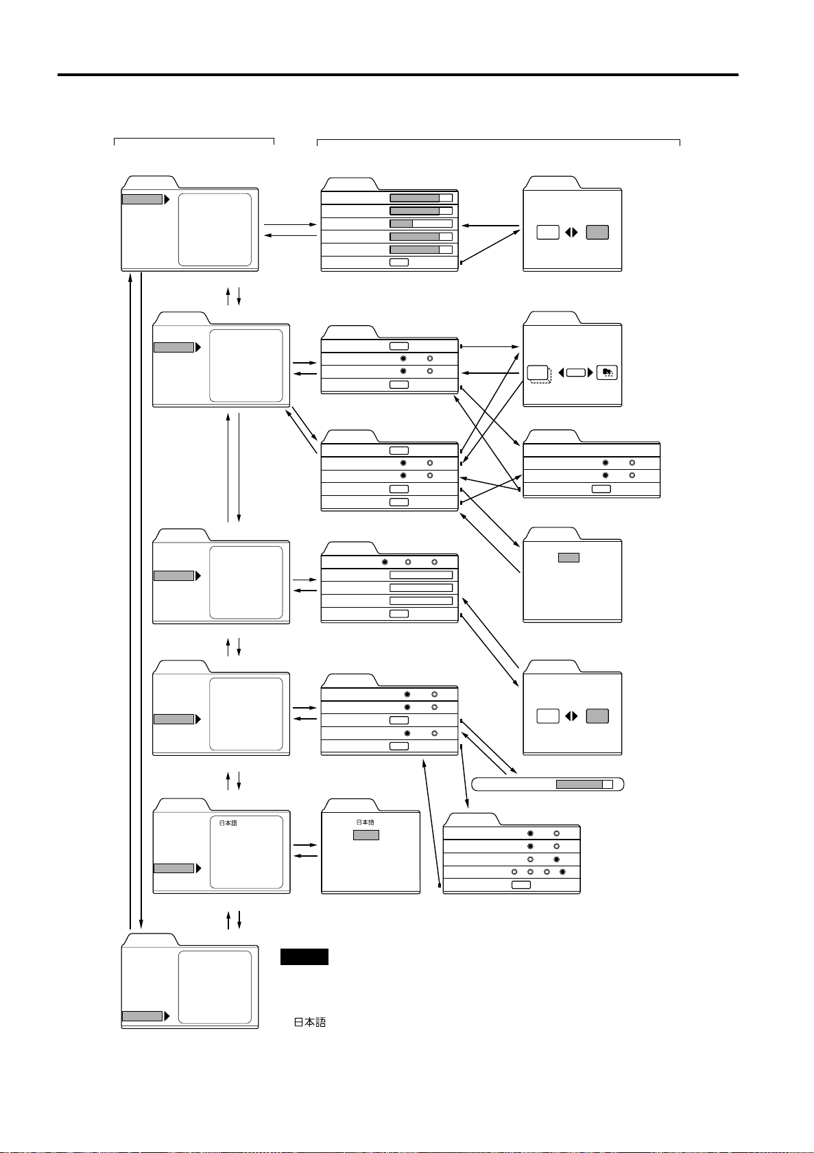
Menu Operations
■ Menu Transition Diagram in Video Menu Mode
Main menu in Video Menu Mode
Press 5/∞ to select an item.
Menu
Image adj.
Setting
Color temp.
Options
Language
Information
Brightness
Contrast
Sharpness
Color
Tint
All reset
5
Position
Tone
Aspect change
Decoder
Tracking
Screen
HDTV
∞
R-Gain
G-Gain
B-Gain
All reset
∞
Menu display
Line display
Keystone
PC2 (BNC)
Right Left rev.
Top Bottom inv.
RS-232C
Sleep time
English
Deutsch
Español
Italiano
Français
∞
∞
5
Menu
Image adj.
Setting
Color temp.
Options
Language
Information
5
Menu
Image adj.
Setting
Color temp.
Options
Language
Information
5
Menu
Image adj.
∞
Setting
Color temp.
Options
Language
Information
5
Menu
Image adj.
Setting
Color temp.
Options
Language
Information
Press 5/∞ to select an item.
Press 2/3 to set or adjust the value.
Image adj.
3 or
ENTER
ESCAPE
Brightness
Contrast
Sharpness
Color
Tint
All reset
Press 5/∞ to select an item.
Press 2/3 to set or adjust the value.
3 or
ENTER
ESCAPE
3 or
ENTER
Setting 1
Position
Tone
Aspect change
Setting 2
Press 5/∞ to select an item.
Press 2/3 to set or adjust the value.
Setting 1
Position
Tone
Aspect change
Decoder
Setting 2
Press 5/∞ to select an item.
Press 2/3 to set or adjust the value.
or
3
ENTER
ESCAPE
3
ENTER
ESCAPE
You can see the information.
Press 5/∞ to select an item.
3
ENTER
ESCAPE
Color temp.
Color temp.
R-Gain
G-Gain
B-Gain
All reset
Press 5/∞ to select an item.
Press 2/3 to set or adjust the value.
or
Options 1
Menu display
Line display
Keystone
PC2 (BNC)
Options 2
Language
or
English
Deutsch
Español
Italiano
Français
Submenus in Video Menu Mode
12
123
123
123
12
12
12
1
ENTER
ENTER
ENTER
ENTER
ENTER
ENTER
ENTER
ENTER
ENTER
ENTER
TV
4:3
TV
4:3
Middle HighLow
15sec
5sec
RGB
ENTER
Cinema
16:9
Cinema
16:9
ESCAPE
ESCAPE
ON
OFF
BPR
YP
Right Left rev.
Top Bottom inv.
RS-232C [bps]
Sleep time [min]
Options 1
ESCAPE
ENTER
ESCAPE
ENTER
ENTER
ENTER
E
N
ESCAPE
Keystone 123
Options 2
ENTER
E
E
N
E
N
T
E
R
Press 2/3 to select Yes or No.
Then, press ENTER to execute.
Image adj.
All reset?
Yes
Press ENTER to select an item.
Press 5/∞ / 2/3 to move the
video screen/menu position.
Position
Disp.Posi. Menu
12,12
E
P
A
C
S
E
N
Press 5/∞ to select an item.
T
E
R
Setting 2
T
E
Tracking
R
Screen
HDTV
Setting 1
T
E
Press 5/∞ to select an item.
R
Decoder
Press 5/∞ to select an item.
Press 2/3 to set or adjust the value.
Color temp.
Yes
OFF
OFF
9600
15 30 60 OFF
ENTER
No
ENTER
123
4:3
1080i
ENTER
AUTO [ NTSC ]
NTSC
NTSC4.43
PAL
SECAM
All reset?
No
ON
ON
19200
16:9
1035i
Press 5/∞ to select an item.
Press 2/3 to set or adjust the value.
Menu
Image adj.
Setting
Color temp.
Options
Language
Information
Input
Switcher
Source
Lamp time
5
VIDEO
CH.0
NTSC
∞
Note
• The display languages of the menus are set to “English” when the projector
is bought. The display language can be selected from the following 6
123 h
languages:
“ (Japanese)”, “English (English)”, “Deutsch (German)”, “Español
(Spanish)”, “Italiano (Italian)” and “Français (French)”. (Refer to page 45.)
The language settings in the section are explained in “English”.
.
38
Page 40
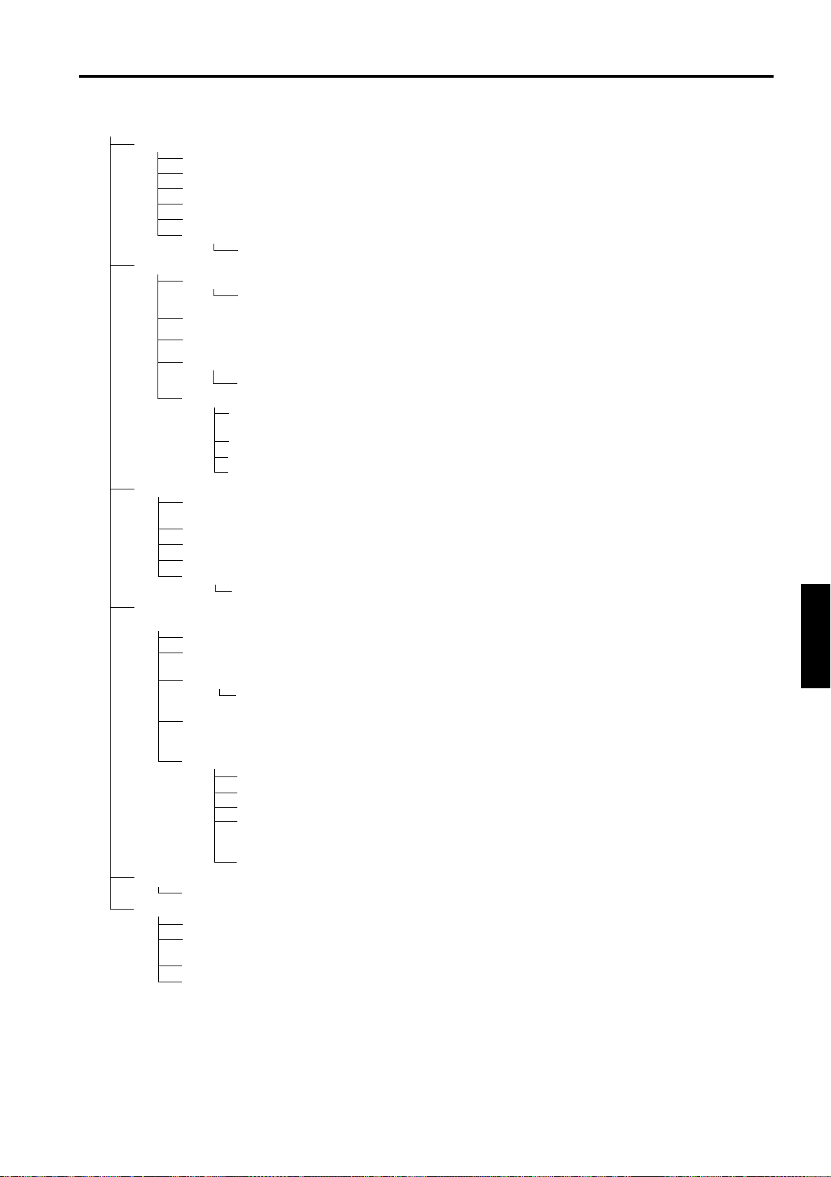
Quick Reference Guide for Video Menu Mode
■
Main Menu in Video Menu Mode (While receiving video-device-related signals)
Image adj.
Setting 1
Color temp.
Options
Options 1
Language
Information
(Refer to page 47)
→
Brightness: Brightness of the video image being projected can be adjusted. (–30 to +30, 0*)
Contrast: Contrast of the video image being projected can be adjusted. (–30 to +30, 0*)
Sharpness: Sharpness of the video image being projected can be adjusted. (–5 to +5, 0*)
Color: Color density of the video image being projected can be adjusted. (–30 to +30, 0*)
Tint: Tint of the video image being projected can be adjusted. (–30 to +30, 0*)
All reset: Resets above items to the factory set values.
Yes / No
Position:
Disp. Posi. / Menu
Tone:
Aspect change:
Decoder:
AUTO*/NTSC/NTSC4.43/PAL/SECAM
Setting 2: Press ENTER to enter the Setting 2 submenu
Tracking: Normally, no adjustment is required. The lateral size and display area of video image can be
Screen:
HDTV:
Setting 1: Press ENTER to return to “Setting 1” submenu.
Color temp.: Adjustable color temperature, Low/Middle*/High.
R-Gain:
G-Gain:
B-Gain:
All-reset:
Yes/No
(Refer to page 52)
→
Menu display:
Line display: 5sec* (Line display such as “VIDEO”, “Y/C”, “PC1”, or “PC2” appears on top right of the screen for
Keystone: Press ENTER to enter the Keystone submenu.
Keystone: Adjust to correct the trapezoidal distortion of the projected image.
PC2 (BNC): RGB* or YP
Options 2: Press ENTER to enter the “Option 2” submenu.
Right Left rev.: OFF* / ON (Select for upside-down hanging on the ceiling.)
Top Bottom inv.: OFF* / ON (Select for upside-down hanging on the ceiling.)
RS-232C [bps]: Selectable baud rate (transmission speed). 9600 / 19200*
Sleep time [min:] Selectable sleep times. If no-signal condition continues for the period of
Options 1: Press ENTER to return to the “Option 1” submenu.
Japanese / English* / German / Spanish / Italian / French
(Refer to page 54)
→
Input: Shows the terminal name selected by the VIDEO or PC button. (Y/C, VIDEO, or PC2)
Switcher: Has no meaning. This display currently has no meaning, (“CH.0” is usually displayed to indicate
Source: Shows the projected image’s type of video signal.
Lamp time: Accumulated used hours of the light-source lamp.
Video screen position and menu position can be adjusted.
Image tone can be changed. TV*/Cinema (Suitable for the cinema programes)
page 50)
Selectable aspect ratio, 4:3*/16:9.
Selectable color systems, Normally, set to AUTO.
(This item is displayed only when inputting VIDEO or Y/C.)
adjusted. (–128 to + 127)
Selectable screen’s aspect ratio. 4:3*/16:9
Selectable HDTV format. Normally, set to 1080i, 1080i*/1035i
Will be adjusted to correct reddish or blueish image.
Adjusts the red leve. (0 to 255, the adjustable range varies depending on signals)
Adjusts the green leve. (0 to 255, the adjustable range varies depending on signals)
Adjusts the blue leve. (0 to 255, the adjustable range varies depending on signals)
Reset above items to the factory set values.
15sec* (Menu disappears in 15 seconds.) / ON (Menu stays on.)
5 seconds when the VIDEO or PC button is pressed.) / OFF (Line display does not appear.)
(–80 to +128, 0*)
BPR
connected to the PC2 terminals. Set to YP
or DTV-format signals (Y, P
Language for on-screen display.
that it is not being used.)
. Set to RGB when a computer device with analog RGB, V, H/Cs signals is
selected time (Unite: Minutes), the projector enters the stand-by mode. 15 / 30
/ 60 / OFF*
(Refer to page 46)
→
B
, PR) are connected to the PC2 terminals.
→
* : Factory set value.
(Refer to page 50)
→
(Refer to page 45)
→
BPR
when a device with component signals (Y, B-Y, R-Y)
(Refer to page 45)
(Refer to page 49)
→
(Refer to page 44)
(Refer to page 45)
→
Menu Operations
(Refer to
→
ENGLISHDEUTSHFRANÇAISITALIANOESPAÑOL
39
Page 41
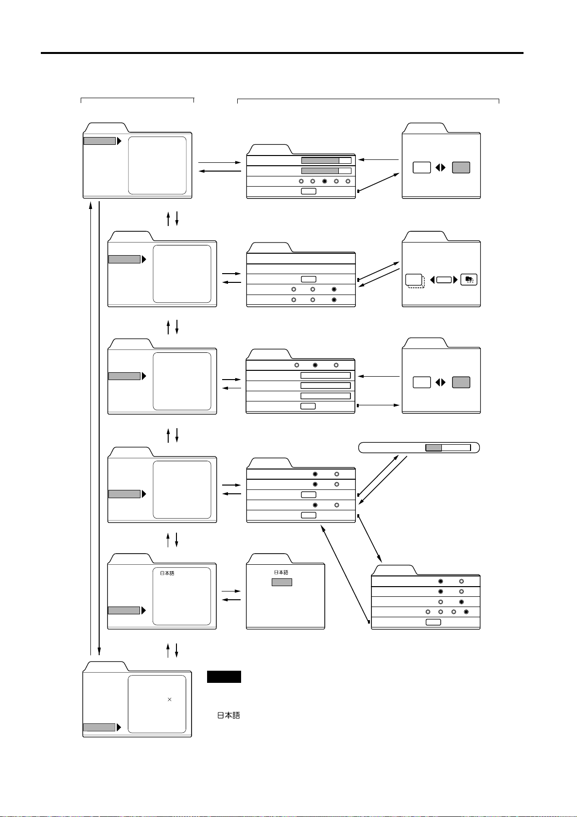
Menu Operations
■ Menu Transition Diagram in PC Menu Mode
Main menu in PC Menu Mode
Press 5/∞ to select an item.
Menu
Image adj.
Setting
Color temp.
Options
Language
Information
Brightness
Contrast
Sharpness
All reset
5
5
Menu
Image adj.
Setting
Color temp.
Options
Language
Information
Tracking
Phase
Position
Resize
Clamp
5
Menu
Image adj.
Setting
Color temp.
Options
Language
Information
R-Gain
G-Gain
B-Gain
All reset
∞
∞
3 or
ENTER
ESCAPE
3 or
ENTER
ESCAPE
3 or
ENTER
ESCAPE
Submenus in PC Menu Mode
Press 5/∞ to select an item.
Press 2/3 to set or adjust the value.
Image adj.
Brightness
Contrast
Sharpness
All reset
12
12
1 2 3 4 5
ENTER
ENTER
Press 5/∞ to select an item.
Press 2/3 to set or adjust the value.
Setting
Tracking
Phase
Position
Resize
Clamp
123
12
ENTER
1:1 Panel Aspect
ST FP BP
ENTER
Press 5/∞ to select an item.
Press 2/3 to set or adjust the value.
Color temp.
Color temp.
R-Gain
G-Gain
B-Gain
All reset
123
123
123
Middle HighLow
ENTER
Press 2/3 to select Yes or No.
Then, press ENTER to execute.
Image adj.
ESCAPE
All reset?
Yes
Press ENTER to select an item.
Press 5/∞ / 2/3 to move the
video screen/menu position.
Position
Disp.Posi. Menu
12,12
ESCAPE
ENTER
Press 2/3 to select Yes or No.
Then, press ENTER to execute.
Color temp.
ESCAPE
ENTER
All reset?
Yes
No
No
5
Menu
Image adj.
Setting
Color temp.
Options
Language
Information
∞
Menu
Image adj.
Setting
Color temp.
Options
Language
Information
Menu display
Line display
Keystone
PC2 (BNC)
Right Left rev.
Top Bottom inv.
RS-232C
Sleep time
5
English
Deutsch
Español
Italiano
Français
5
Menu
Image adj.
Setting
Color temp.
Options
Language
Information
Input
Switcher
Resolution
Frequency H
Frequency V
Lamp time
PC 1
1280 1024
79.9
75
123
You can see the information.
CH.0
kHz
Hz
h
∞
Press 5/∞ to select an item.
Press 2/3 to set or adjust the value.
3 or
ENTER
ESCAPE
Options 1
Menu display
Line display
Keystone
PC2 (BNC)
Options 2
15sec
5sec
ENTER
RGB
ENTER
ON
OFF
YP
BPR
Keystone 0
ENTER
ESCAPE
ENTER
∞
Press 5/∞ to
ENTER
select an item.
Language
Options 2
English
Deutsch
Español
Italiano
Français
Right Left rev.
Top Bottom inv.
RS-232C [bps]
Sleep time [min]
Options 1
OFF
OFF
9600
15 30 60 OFF
ENTER
Press 5/∞ to select an item.
∞
Press 2/3 to set or adjust the value.
Note
• The display languages of the menus are set to “English” when the projector is
bought. The display language can be selected from the following 6 languages:
“ (Japanese)”, “English (English)”, “Deutsch (German)”, “Español
(Spanish)”, “Italiano (Italian)” and “Français (French)”. (Refer to page 45.)
The language settings in the section are explained in “English”.
ON
ON
19200
40
Page 42
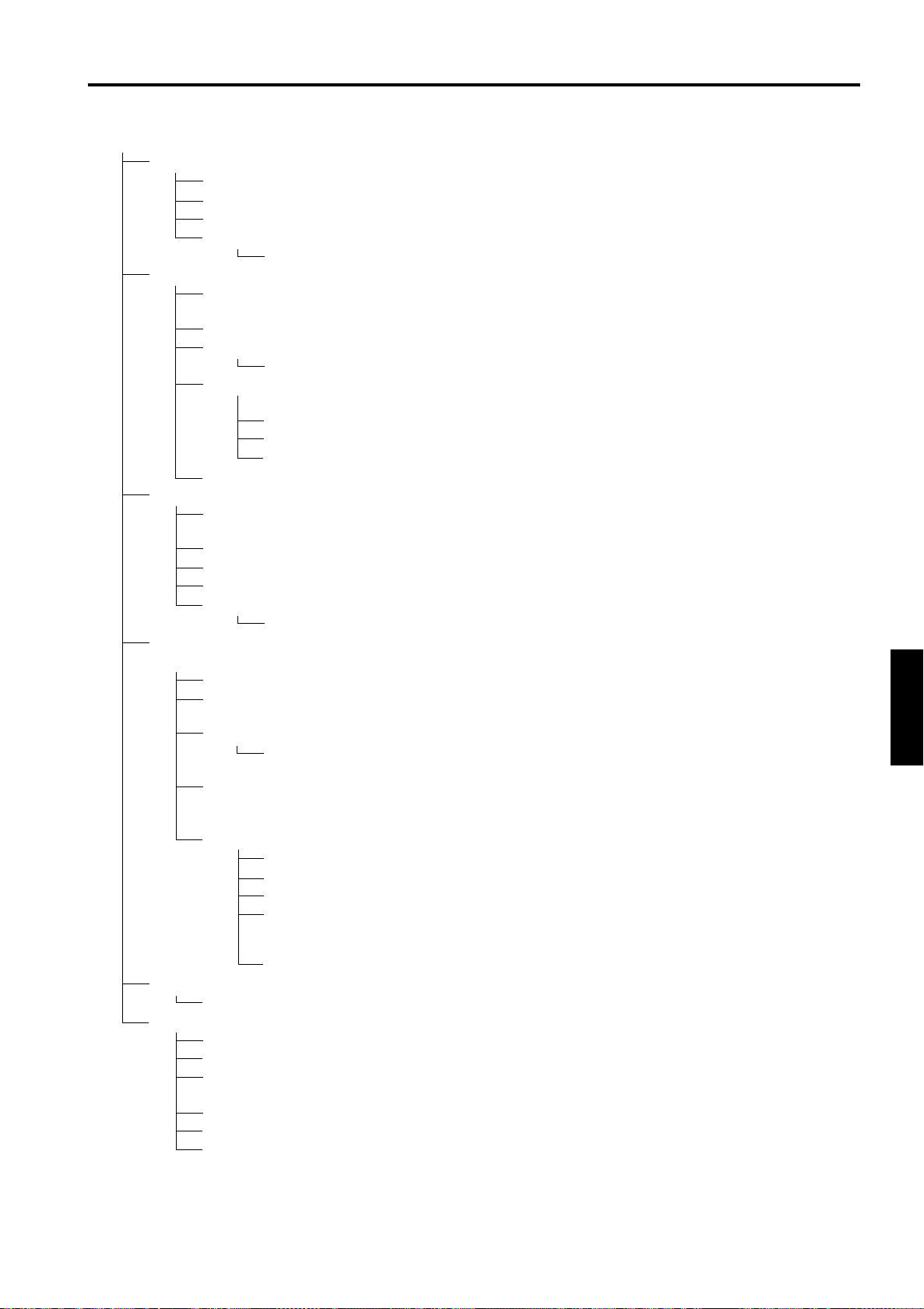
Quick Reference Guide for PC Menu Mode
■
Main Menu in PC Menu Mode (While receiving computer-related signals)
Image adj. → (Refer to page 47)
Brightness: Brightness of the picture image being projected can be adjusted. (–30 to +30, 0*)
Contrast: Contrast of the picture image being projected can be adjusted. (–30 to +30, 0*)
Sharpness: Adjust the outline of letters etc. (1 / 2 / 3 / 4 / 5, 3*)
All reset: Resets above items to the factory set values.
Yes / No
Setting
Tracking: The lateral size and display area of picture image can be adjusted. (–128 to +127)
→ (Refer to page 46)
Phase: Flickering or dim picture image can be adjusted. (0 to 31) → (Refer to page 46)
Position: Video screen position and menu position can be adjusted. → (Refer to page 49)
Disp. Posi. / Menu
Resize: The relationship between the number of pixels (resolution) and the screen can be selected.
→ (Refer to page 51)
“1:1”: Picture image is projected with its original size.
Panel: Picture image is enlarged to the full size.
Aspect*: Picture image is enlarged while maintaining the original aspect ratio.
Clamp: Selectable clamp position. Normally, set to “BP”. ST / FP / BP*
Color temp.
Color temp.:
R-Gain:
G-Gain:
B-Gain:
All-reset:
Options → (Refer to page 52)
Options 1
Menu display: 15sec* (Menu disappears in 15 seconds.) / ON (Menu stays on.)
Line display: 5sec* (Line display such as “PC1” or “PC2” appears on top right of the screen for 5 seconds
Keystone: Press ENTER to enter th e Keystone submenu.
PC2 (BNC): RGB* or YP
Options 2: Press ENTER to enter the “Option 2” submenu.
Language Language for on-screen display. → (Refer to page 45)
Japanese / English* / German / Spanish / Italian / French
Information → (Refer to page 54)
Input: Shows the terminal name selected by the PC button. (PC1or PC2)
Switcher:
Resolution: Shows the resolution of the input signal being received. (Horizontal × Vertical)
Frequency H: Shows the horizontal frequency of the input signal being received. ( kHz)
Frequency V: Shows the vertical frequency of the input signal being received. ( Hz)
Lamp time: Accumulated used hours of the light-source lamp.
* : Factory set value.
Adjustable color temperature, Low/Middle* /High.
Will be adjusted to correct reddish or blueish image.
Adjusts the red level. (o to 255, the adjustable range varies depending on signals)
Adjusts the green level. (o to 255, the adjustable range varies depending on signals)
Adjusts the blue level. (o to 255, the adjustable range varies depending on signals)
Reset above items to the factory set values.
Yes/No
when the VIDEO or PC button is pressed.) / OFF (Line display does not appear.)
Keystone: Adjust to correct the trapezoidal distortion of the projected image.
(–80 to +128, 0*)
. Set to RGB when a computer device with analog RGB, V, H/Cs signals is
BPR
connected to the PC2 terminals. Set to YP
Y, R-Y) or DTV-format signals (Y, P
Right Left rev.: OFF* / ON (Select for upside-down hanging on the ceiling.)
Top Bottom inv.: OFF* / ON (Select for upside-down hanging on the ceiling.)
RS-232C [bps]: Selectable baud rate (transmission speed). 9600 / 19200*
Sleep time [min:] Selectable sleep times. If no-signal condition continues for the period
of selected time (Unite: Minutes), the projector enters the stand-by
mode. 15 / 30 / 60 / OFF*
Options 1: Press ENTER to return to the “Option 1” submenu.
This display currently has no meaning. (“CH.0” is usually d is p layed to indicate that it is not being used.)
It may not be displayed correctly with some input signals.
B
Menu Operations
when a device with component signals (Y, B-
BPR
, PR) are connected to the PC2 terminals.
ENGLISHDEUTSHFRANÇAISITALIANOESPAÑOL
41
Page 43
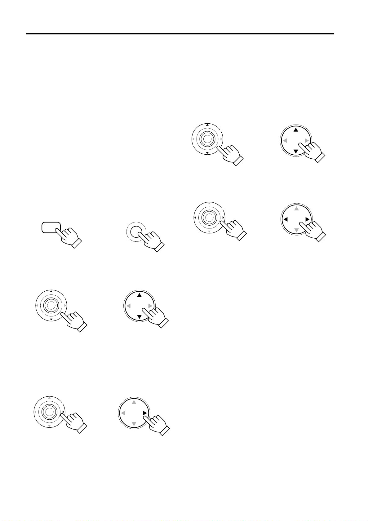
Menu Operations
Basic Menu Operation
When the MENU button is pressed, the projector enters Video or PC menu mode by responding to the input sig nal being
received.
Video menu mode:
Enters this mode when video-device-related signals are
input from the following devices.
• Video devices connected to the VIDEO IN (Y/C and
VIDEO) terminals.
• A video device connected to the PC 2 terminals, which
outputs component signals (Y, B-Y, R-Y) or DTV-format
signals (Y, PB
, PR).
PC menu mode:
Enters this mode when computer-related signals are input
from the following devices.
• A computer connected to the PC 1 terminal.
• A computer connected to the PC 2 terminal, which outputs
analog RGB, V, H/Cs signals.
Press the MENU button.
1
The main menu is displayed on the screen.
Remote control unit Projector
MENU
Press the cursor button 5 or ∞∞∞∞ to
2
MENU
select an item in the main menu.
Remote control unit
E
N
T
E
R
Press the cursor button 3333 or the
3
Projector
ENTER button to enter the submenu.
The submenu corresponding to the item selected in step
2 is displayed on the screen.
* When you selected “Information” in step 2, no
submenu is available.
Remote control unit
E
N
T
E
R
Projector
Press the cursor button 5 or ∞∞∞∞ to
4
select an item in the submenu.
When a “Language” has been selected in step 2, press
to set the language.
Remote control unit
E
N
T
E
R
Press the cursor button 2222 or 3333 to set
5
Projector
or adjust the value.
Remote control unit
E
N
T
E
R
When an item which has the “ENTER” message has been
selected in step 4, press the ENTER button to move to the
next submenu.
• All reset → (Refer to page 47)
• Position → (Refer to page 49)
• Decoder
(Refer to page 44)
→
• Keystone → (Refer to page 52)
• Options 1 → (Refer to page 52)
• Options 2
(Refer to page 52)
→
To exit the main menu:
• While the main menu is displayed, press the MENU button.
The main menu disappears and the original picture image
resumes.
To exit the submenu:
• While the submenu is displayed, press the ESCAPE
button.
The menu returns to the previous menu.
• To exit the menu mode directly, press the MENU button.
The submenu disappears and the original video image is
restored.
Projector
42
Page 44
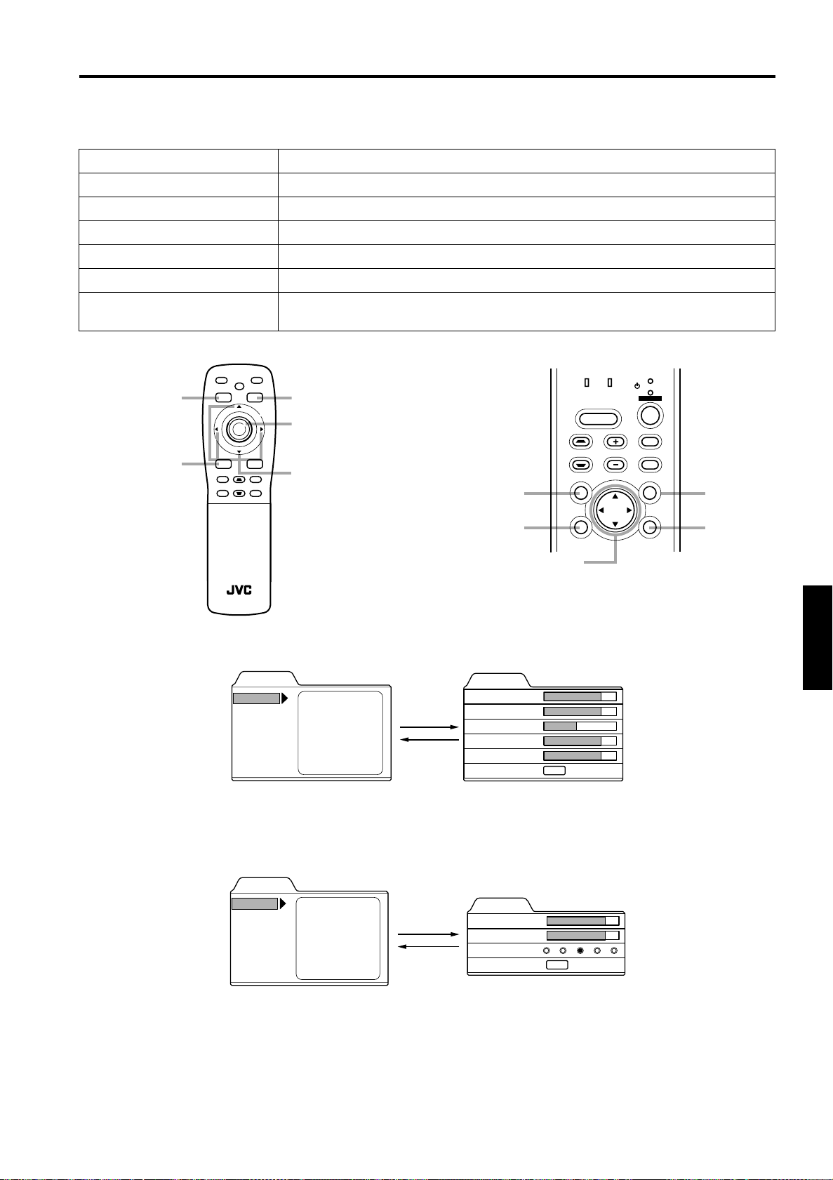
Menu Operations
Basic Menu Operation (Cont.)
Basic Button Functions in the Menu Mode
■
Button Function
MENU Enters the main menu or exits the menu mode.
Cursor button 5/∞ Selects an item in the menu. Pressing ∞ or 5 will scroll the item in the menu.
Cursor button 2/3 Sets or adjusts the value.
PRESET If pressed while the keystone setting submenu is displayed, the value is set to “0”.
ESCAPE Returns to the previous menu.
ENTER
■ Remote control unit ■ Projector
FREEZE
HIDE
PRESET button
ESCAPE button
PRESET
ESCAPE
+
DIGITAL
KEYSTONE
ZOOM
–
T
U
ZOOM
SHIFT
W
D
+
QUICK
SHUTER
ALIGN.
–
RM-M2000 REMOTE CONTROL UNIT
Used to enter the submenu from the main menu.
Used to enter the next submenu if “ENTER” is displayed in the selected item.
OPERATE
MENU
E
VIC SELECT
VIDEO
VOLUME
N
PC
FOCUS
T
E
R
+
–
+
–
MENU button
ENTER button
Cursor buttons
5/∞ / 2/3
PRESET
button
ESCAPE
button
LAMP TEMP
HIDE
KEYSTONE VOLUME
PRESET
ESCAPE ENTER
Cursor buttons
5/∞ / 2/3
STAND BY
OPERATE
PC
VIDEO
MENU
MENU
button
ENTER
button
■ Video menu mode
Press 5/∞ to select an item.
■ PC menu mode
PC main menu
Image adj.
Setting
Color temp.
Options
Language
Information
Press 5/∞ to select an item.
Video main menu
Menu
Image adj.
Setting
Color temp.
Options
Language
Information
Menu
Brightness
Contrast
Sharpness
Color
Tint
All reset
Brightness
Contrast
Sharpness
All reset
3 or
ENTER
ESCAPE
3 or
ENTER
ESCAPE
Video submenu
Image adj.
Brightness
Contrast
Sharpness
Color
Tint
All reset
12
12
1
12
12
ENTER
Press 5/∞ to select an item.
Press 2/3 to set or adjust the value.
PC submenu
Image adj.
Brightness
Contrast
Sharpness
All reset
12
12
1 2 3 4 5
ENTER
Press 5/∞ to select an item.
Press 2/3 to set or adjust the value.
ENGLISHDEUTSHFRANÇAISITALIANOESPAÑOL
43
Page 45
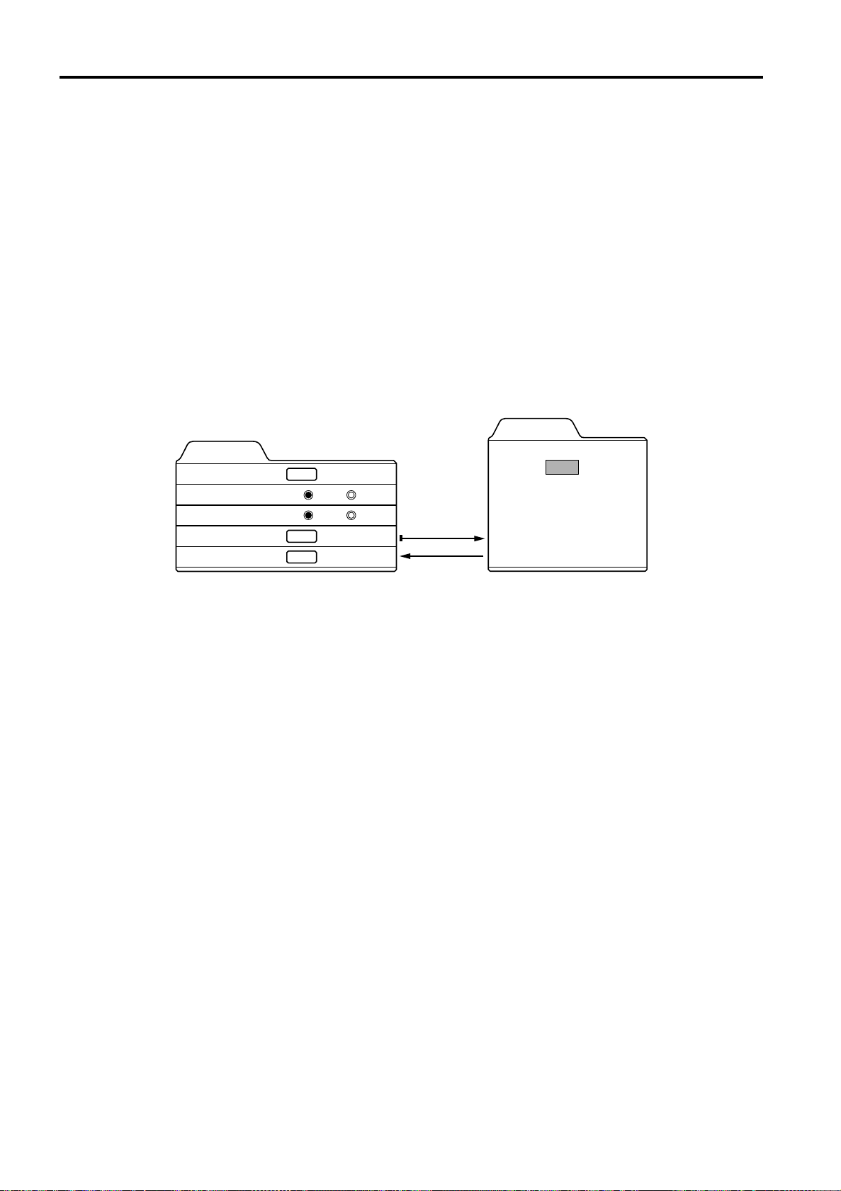
Menu Operations
Changing the Color System (Video Menu Mode Only)
This function is available only in Video menu mode.
The menu is only displayed when there is a signal for the AV IN (Y/C and VIDEO) terminal, and not displayed when there is a
signal for the PC2 terminal.
Normally, use the color system in AUTO. If operation in AUTO is unstable, such as color not being shown, set to a dedicated
color system in accordance with the color system of the video signal being input.
Press the MENU button.
1
The main menu appears on the screen.
Select “Setting” with the cursor button 5 or ∞∞∞∞, and press 3333 or the ENTER button.
2
The “Setting 1” submenu appears on the screen.
Select “Decoder” with the cursor button 5 or ∞∞∞∞, and press the ENTER button.
3
The “Decoder” submenu appears on the screen.
Video submenus
Decoder
Setting 1
Position
Tone
Aspect change
Decoder
Setting 2
ENTER
ENTER
ENTER
TV
4:3
Cinema
16:9
ENTER
ESCAPE
AUTO [ NTSC ]
NTSC
NTSC4.43
PAL
SECAM
Set the color system with the cursor button 5 or ∞∞∞∞.
4
AUTO: Normally, set to “AUTO”. (Factory set value)
The color system of a video signal being input is automatically identified and displayed in [ ].
In [ ], B/W (Black & White), NTSC, NTSC4.43, PAL or SECAM will be displayed. (It is not always displayed.)
For example, AUTO [ NTSC ] shows that the NTSC signal is being received.
NTSC: Dedicated to NTSC.
NTSC4.43:Dedicated to NTSC4.43.
PAL: Dedicated to PAL.
SECAM: Dedicated to SECAM.
Press the ESCAPE button to return to the previous menu or press the MENU button
5
to exit the menu mode.
44
Page 46
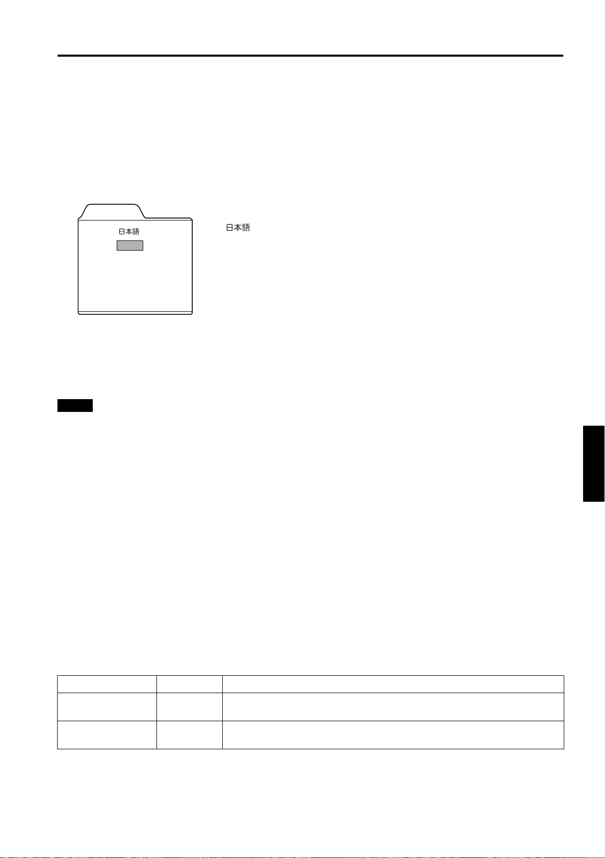
Menu Operations
Changing the Language Display
The on-screen language is set to “English” when shipped from the factory. When you want to change to another language, set
it as follows.
Press the MENU button.
1
The main menu appears on the screen.
Select “Language” with the cursor button 5 or ∞∞∞∞, and press 3333 or the ENTER button.
2
The “Language” submenu appears on the screen.
Language
: Japanese
English
Deutsch
Español
Italiano
Français
Set the language with the cursor button 5 or ∞∞∞∞.
3
English : English
Deutsch : German
Español : Spanish
Italiano : Italian
Français : French
Press the ESCAPE button to return to the previous menu or press the MENU button
4
to exit the menu mode.
Memo
About language display
Some words in the menu and messages such as “Quick Alignment”, “Keystone”, “VIDEO” and “NTSC” are shown only in
English.
Changing the Screen aspect ratio/HDTV format (Video Menu
Mode Only)
Press the MENU button.
1
The main menu appears on the screen.
Select “Setting” with the cursor button 5 or ∞∞∞∞, and press 3333 or the ENTER button.
2
The “Setting 1” submenu appears on the screen.
Select “Setting 2” with the cursor button 5 or ∞∞∞∞, and press 3333 or the ENTER button.
3
The “Setting 2” submenu appears on the screen.
Select “Screen” or “HDTV” with the cursor button 5 or ∞∞∞∞.
4
Adjust the Screen aspect ratio or HDTV format with the cursor button 2222 or 3333.
5
To adjust multiple items, repeat 4 and 5.
ENGLISHDEUTSHFRANÇAISITALIANOESPAÑOL
Adjustment item Button Adjustment content
Screen 2 or 3
HDTV 2 or 3
Press the ESCAPE button to return to the previous menu or press the MENU button
6
Select according to the aspect ratio of the screen used.
4:3 16:9
Set the number of effective scanning lines. Normally, select 1080i.
1080i: 1035i:
to exit the menu mode.
45
Page 47
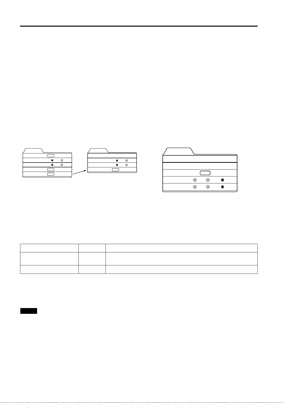
Menu Operations
Adjusting Tracking / Phase
Normally, tracking and phase adjustments are automatically carried out when a video signal is input to the projector for the
first time, or when the QUICK ALIGN. button on the remote control is pressed.
However, you can manually adjust the tracking and phase on the menu.
Both tracking and phase can be adjusted in PC menu mode. In Video menu mode, only tracking is adjustable, th ough this
adjustment is not normally required.
If a wide stripe appears on the screen, adjust the lateral size of the picture image and the display area (tracking adjustment)
so the stripe disappears.
Also, if text projected on the screen appears flickers or appears dim, adjust phase adjustment so it becomes clear.
Press the MENU button.
1
The main menu appears on the screen.
Select “Setting” with the cursor button 5 or ∞∞∞∞, and press 3333 or the ENTER button.
2
The “Setting 1” (video mode) or “Setting” submenu appears on the screen.
In video mode:Select setting 2 with the cursor ∞ or 5, and press ENTER button.
The “Setting 2” submenu appears on the screen.
Video submenu PC submenu
Setting 1
Position
Tone
Aspect change
Decoder
Setting 2
ENTER
ENTER
ENTER
TV
Cinema
4:3
16:9
Decoder is only displayed when there is a signal for the AV
IN terminal.
Select “Tracking” or “Phase” with the cursor button 5 or ∞∞∞∞.
3
Setting 2
Tracking
Screen
HDTV
Setting 1
123
ENTER
4:3
1030i
16:9
1035i
Tracking
Phase
Position
Resize
Clamp
Setting
123
12
ENTER
1:1 Panel Aspect
ST FP BP
*“Phase” is shown only in PC submenu.
Adjust the tracking or phase with the cursor 2222 or 3333.
4
Adjust the tracking and phase of the picture image being projected. To adjust the phase, first check for correct tracking
adjustment.
*To adjust multiple items, repeat 3 and 4.
Adjustment item Button Adjustment content
Tracking 2 or 3
The picture image shrinks laterally (right-to-left) or extends laterally (left-toright). (–128 ↔ +127)
Phase 2 or 3 Set to a position where text appears clear. (PC menu mode only) (0 ↔ 31)
Press the ESCAPE button to return to the previous menu or press the MENU button
5
to exit the menu mode.
Note
• A dim image could be caused by insufficient adjustment of brightness and contrast. Before adjusting phase, make sure that
brightness and contrast are correctly adjusted. To adjust them, refer to “Adjusting Picture Quality” on page 47.
46
Page 48
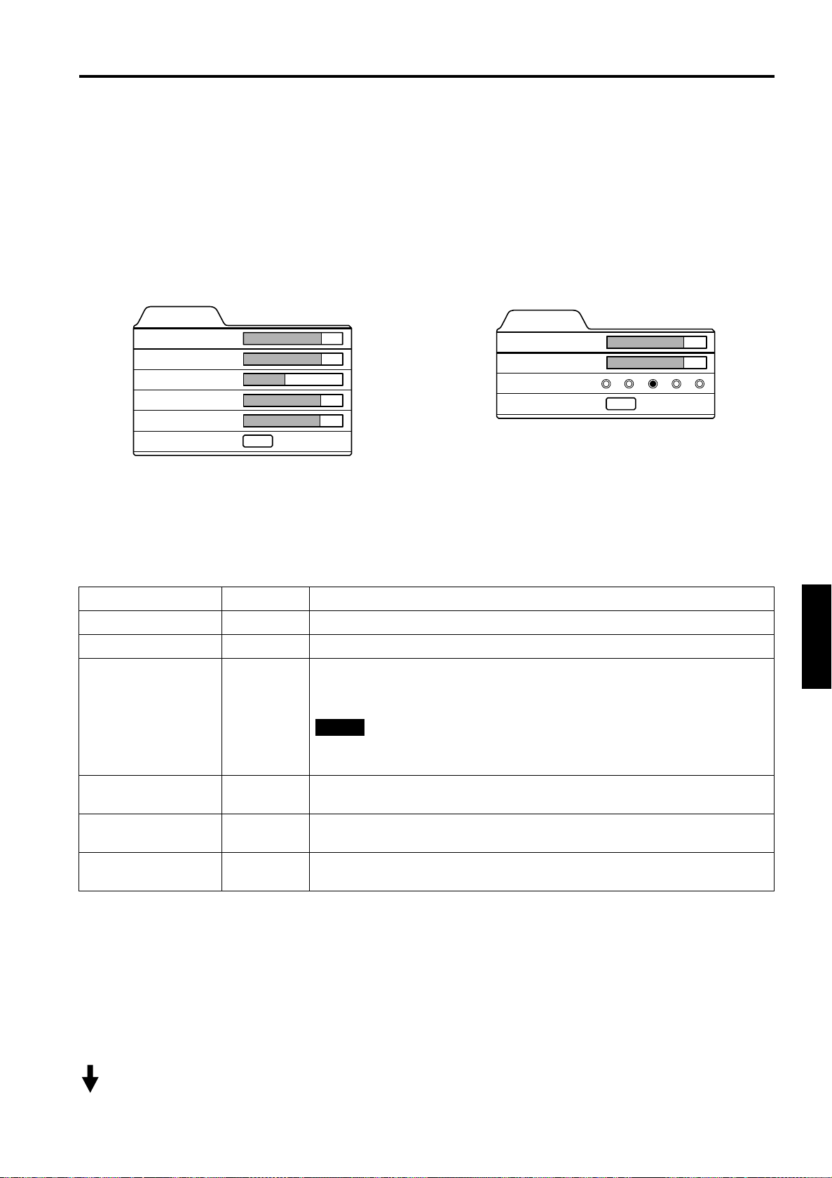
Menu Operations
Adjusting Picture Quality
In the “Image adj.” submenu, adjust brightness, contrast, sharpness, etc. to obtain the desired picture quality. Note that the
adjustment items differ in Video menu mode and PC menu mode.
Press the MENU button.
1
The main menu appears on the screen.
Select “Image adj.” with the cursor button 5555 or ∞∞∞∞, and press 3333 or the ENTER button.
2
The “Image adj.” submenu appears on the screen.
Video submenu PC submenu
Image adj.
Brightness
Contrast
Sharpness
Color
Tint
All reset
Select the item to be adjusted with the cursor button 5555 or ∞∞∞∞.
3
*“Color” and “Tint” are shown in Video submenu only.
Make adjustment with the cursor 2222 or 3333.
4
*To adjust multiple items, repeat 3 and 4.
Adjustment item Button Adjustment content
Brightness 2 or 3 Gets darker/brighter. (–30 ↔ 0* ↔ +30)
Contrast 2 or 3 Gets lower/higher. (–30 ↔ 0* ↔ +30)
Sharpness 2 or 3
Color
12
12
1
12
12
ENTER
Gets softer/sharper.
• Video menu mode: (–5 ↔ 0* ↔ +5)
• PC menu mode: (1 ↔ 3* ↔ 5)
Note
• When in the PC menu mode, if the resize function in the PC submenu is set to
“1:1”, the image quality will not change even if the value is changed.
or
2
Gets softer/deeper. (–30 ↔ 0* ↔ +30)
3
(Video menu mode only)
Image adj.
Brightness
Contrast
Sharpness
All reset
12
12
1 2 3 4 5
ENTER
ENGLISHDEUTSHFRANÇAISITALIANOESPAÑOL
Tint
All reset ENTER
* : Factory set value
or
2
Gets reddish/greenish. (–30 ↔ 0* ↔ +30)
3
(Video menu mode only)
Resets above items to the factory set values. How to operate is mentioned below
(next page).
■ To perform All Reset
• In the Image adj. submenu, select “All reset” with the cursor button 5 or ∞, and press the ENTER button. Then, the “All
reset” submenu appears on the screen.
• Press the cursor button 2 to select “Yes”, and then press the ENTER button.
• All items in the “Image adj.” submenu are reset to the factory set values and the menu returns to the previous one.
To exit the “All reset” submenu without performing All reset, select “No” with the cursor button 3 and, press the ENTER
button.
(To be continued on the next page)
47
Page 49
Menu Operations
.
Image adj.
All reset?
Yes
Press the ESCAPE button to return to the previous menu or press the MENU button
5
No
to exit the menu mode.
Memo
In some adjustments, the level bar changes according to the set value. (The setting value is also displayed at the left of the
level bar.)
Adjusting Color temperature
1
Press the MENU button.
The main menu appears on the screen.
Select “Color temp.” with the cursor button 5555 or ∞∞∞∞, and press 3333 or the ENTER
2
button.
The “Color temp.” submenu appears on the screen.
Select “Color temp.” with the cursor button 5555 or ∞∞∞∞.
3
Adjust the color temperature with the cursor button 2222 or 3333.
4
Low: Color temperature decreases (image becoming reddish).
Middle: Results in middle color temperature. (Factory set position).
High: Color temperature increases (image becoming blueish).
Select “R-Gain” or “G-Gain” or “B-Gain” with the cursor button 5 or ∞∞∞∞.
5
Fine adjust the color temperature with the cursor button 2222 or 3333.
6
To adjust multiple items, repeat 5 and 6.
Adjustment item Button Adjustment content
R-Gain 2 or 3 Adjusts the red level. (0 to 255)
G-Gain
B-Gain 2 or 3 Adjusts the blue level. (0 to 255)
or
2
Adjusts the green level. (0 to 255)
3
■ To perform All Reset
• In the Color temp. submenu, select “All res et” with the cursor button 5 or ∞, and press the ENTER button. Then, the “All
reset” submenu appears on the screen.
• Press the cursor button 2 to select “Yes”, and then press the ENTER button.
• All items in the Color temp. submenu are reset to the factory set values and the menu returns to the previous one.
To exit the “All reset” submenu without performing All reset, select “No” with the cursor button 3 and, press the ENTER
button.
Press the ESCAPE button to return to the previous menu or press the MENU button
7
to exit the menu mode.
48
Page 50
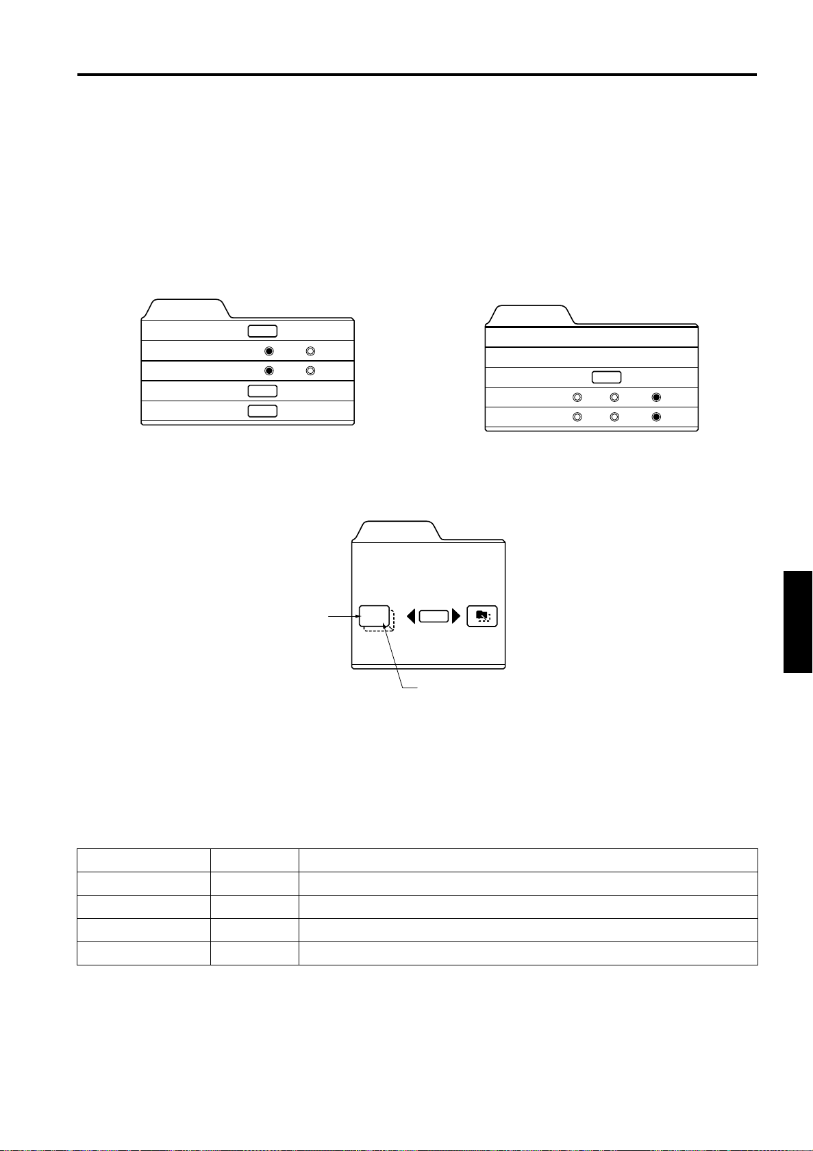
Menu Operations
Adjusting the Video Screen/Menu Position
The position of the video screen and the menu on the video screen can be adjusted. You can finely adjust the video screen
position. The menu will move widely on the video screen.
Press the MENU button.
1
The main menu appears on the screen.
Select “Setting” with the cursor button 5555 or ∞∞∞∞, and press 3333 or the ENTER button.
2
The “Setting 1” or “Setting” submenu appears on the screen.
Video submenu (“Setting 1” submenu) PC submenu (“Setting” submenu)
Setting 1
Position
Tone
Aspect change
Decoder
Setting 2
Decoder is only displayed when there is a
signal for the Video IN terminal.
Select “Position” with the cursor button 5555 or ∞∞∞∞, and press the ENTER button.
3
The “Position” submenu appears on the screen.
ENTER
TV
4:3
ENTER
ENTER
Horizontal position
Cinema
16:9
Position
Disp.Posi. Menu
12,12
ENTER
Vertical position
Tracking
Phase
Position
Resize
Clamp
Setting
123
12
ENTER
1:1 Panel Aspect
ST FP BP
ENGLISHDEUTSHFRANÇAISITALIANOESPAÑOL
Press the ENTER button to select “Disp.Posi.” or “Menu”.
4
Disp.Posi. (Display Position):The video screen position (display position) can be adjusted.
Menu:The menu position can be adjusted.
Press the cursor button 5555, ∞∞∞∞, 2222, or 3333 to move the video screen (display) or the
5
menu.
*Repeat 4 and 5 to move both video screen (display) and menu positions.
Adjustment item Button Adjustment content
Disp.Posi. - H
Disp.Posi. - V 5 or ∞ The video screen moves up or down. (–30 ↔ +30)
Menu - H 2 or 3 The menu moves to the left or right. (Left, center*, right)
Menu - V 5 or ∞ The menu moves up or down. (Top, center*, bottom)
* : Factory set value
Press the ESCAPE button to return to the previous menu or press the MENU button
6
or
2
3
The video screen moves to the left or right. (–30 ↔ +30)
to exit the menu mode.
49
Page 51
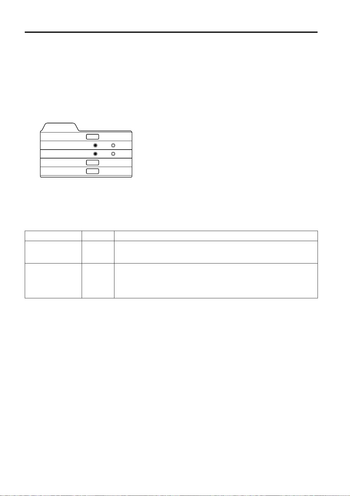
Menu Operations
Changing the Image Tone/Aspect Ratio (Video Menu Mode Only)
The image tone (TV or Cinema) and the aspect ratio (4:3 or 16:9) are selectable in Video menu mode.
Press the MENU button.
1
The main menu appears on the screen.
Select “Setting” with the cursor button 5555 or ∞∞∞∞, and press 3333 or the ENTER button.
2
The “Setting 1” submenu appears on the screen.
Video submenu
Setting 1
Position
Tone
Aspect change
Decoder
Setting 2
Decoder is only displayed when there is a signal for the Video IN terminal.
ENTER
ENTER
TV
4:3
Cinema
16:9
Select “Tone” or “Aspect change” with the cursor button 5555 or ∞∞∞∞.
3
Adjust the image tone or aspect ratio with the cursor 2222 or 3333.
4
*To adjust multiple items, repeat 3 and 4.
Adjustment item Button Adjustment content
The image tone projected on the screen can be changed.
Tone
Aspect change 2 or 3
* : Factory set value
Press the ESCAPE button to return to the previous menu or press the MENU button
5
or
2
TV* : Suitable for projecting the video programs.
3
Cinema : Suitable for projecting the cinema programs.
Sets the vertical-to-horizontal ratio (4:3 or 16:9) of the video image projected.
“4:3*” : The aspect ratio of the projected image becomes 4:3. Set it to 4:3 for video
of NTSC, NTSC4.43, PAL, SECAM.
“16:9” : The aspect ratio of projected image becomes 16:9. Set it to 16:9 for Hi-
Vision devices (W-VHS VCR, etc.).
to exit the menu mode.
50
Page 52
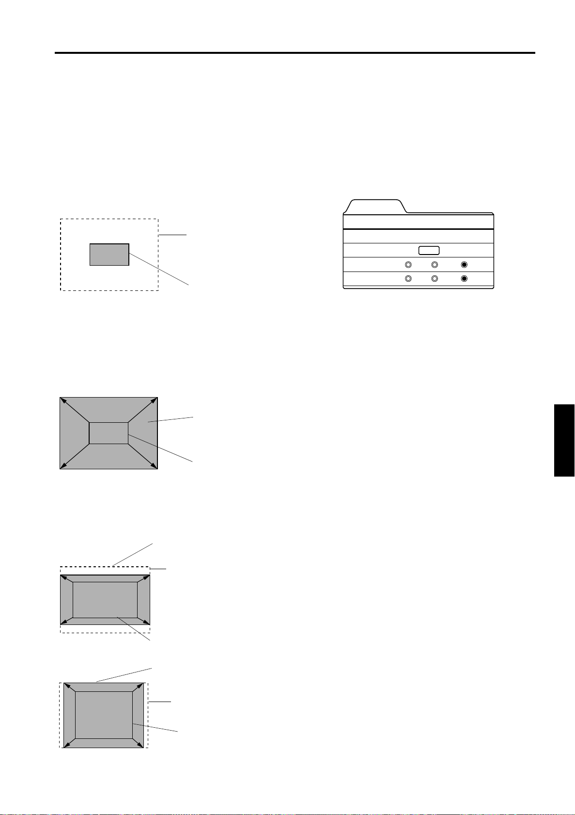
Menu Operations
Changing the Image Size - Resize Function (PC Menu Mode Only)
The picture image projected can be selectable with the
Resize function which is available only in PC menu mode.
You can choose the video image size projected from the
following: (Factory setting is “Aspect”.)
“1:1”: The image is displayed at the input resolution. The
picture image projected is not enlarged even if its
number of pixels (resolution) is smaller than that of
the projector’s D-ILA element (1365 pixels × 1024
pixels).
Resize: 1:1
Full size (1365 × 1024)
Image not enlarged
Panel: The picture image projected is virtually enlarged to
the full size (1365 pixels × 1024 pixels). The
horizontal and vertical enlargement ratio will differ
depending on the original image and the image will
be deformed.
Resize: Panel
Press the MENU button.
1
The main menu appears on the screen.
Select “Setting” with the cursor button
2
5
5 or ∞∞∞∞, and press 3333 or the ENTER
55
button.
The “Setting” submenu appears on the screen.
PC submenu
Setting
Tracking
Phase
Position
Resize
Clamp
Select “Resize” with the cursor button
3
5
5 or ∞∞∞∞.
55
Choose “1:1”, “Panel”, or “Aspect”
4
123
12
ENTER
1:1 Panel Aspect
ST FP BP
with the cursor button 2222 or 3333.
Press the ESCAPE button to return to
5
the previous menu or press the MENU
button to exit the menu mode.
Image enlarged
to the full size
(1365 × 1024)
Image not enlarged
(Original image)
Aspect:While maintaining the original aspect ratio, the video
image projected is virtually enlarged until either the
horizontal or vertical side reaches the full size (1365
pixels × 1024 pixels).
Resize: Aspect
Image enlarged to the aspect size.
(Example: aspect ratio is 16:9)
Full size (1365 × 1024)
Image not enlarged (original image)
(Example: aspect ratio is 16:9)
Image enlarged to the aspect size.
(Example: aspect ratio is 5:4)
Full size (1365 × 1024)
Changing the Clamp pulse position
(PC Menu Mode Only)
When the image is too dark or bright, or when the image is
unstable, switching the position may improve the image
quality. Normally, set to “BP”.
Press the MENU button.
1
The main menu appears on the screen.
Select “Setting” with the cursor button
2
5
5 or ∞∞∞∞, and press 3333 or the ENTER
55
button.
The “Setting” submenu appears on the screen.
Select “Clamp” with the cursor button
3
5
5 or ∞∞∞∞.
55
Choose “ST”, “FP”, or “BP” with the
4
cursor button 2222 or 3333.
Press the ESCAPE button to return to
5
the previous menu or press the MENU
button to exit the menu mode.
ST: Sync Tip FP: Front Porch BP: Back Porch
ENGLISHDEUTSHFRANÇAISITALIANOESPAÑOL
Image not enlarged
(original image)
(Example: aspect ratio is 5:4)
51
Page 53
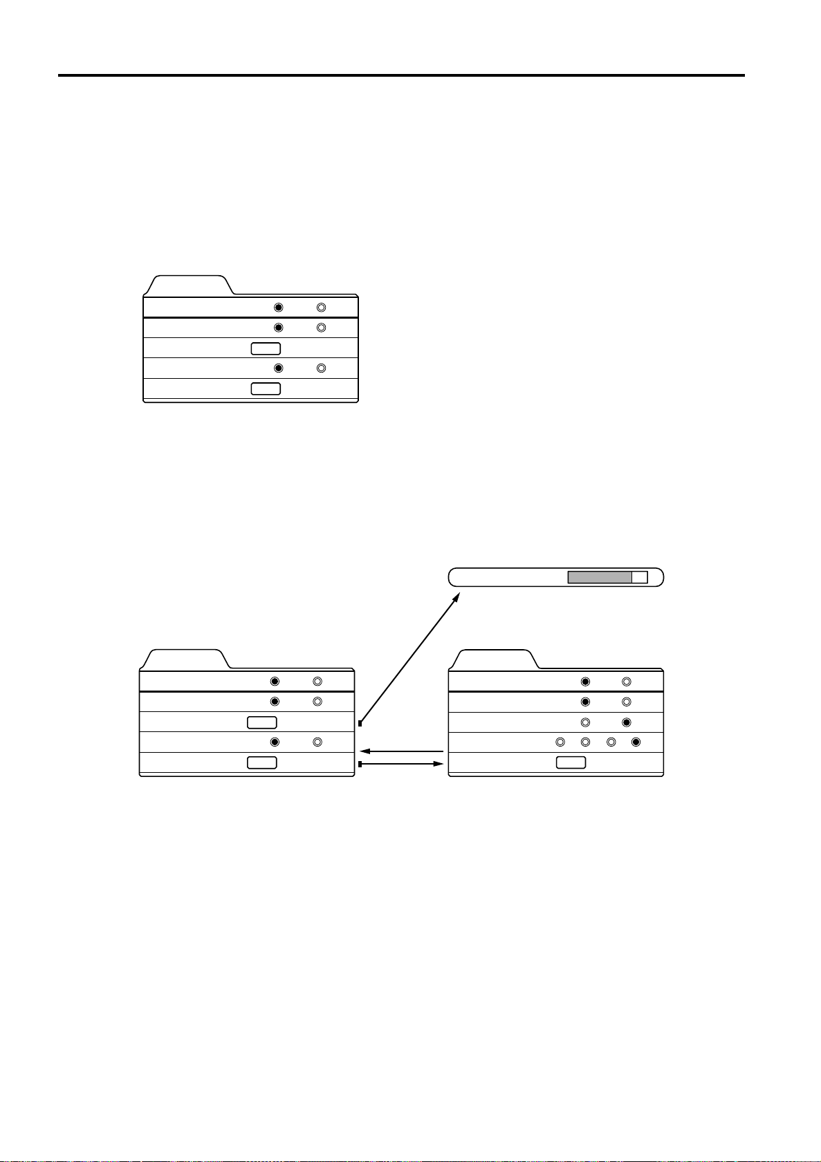
Menu Operations
Setting and Adjusting Other Functions (OPTIONS)
Various functions are provided as shown in the “Options 1” and “Options 2” submenus.
You can set or adjust each function, as required.
Press the MENU button.
1
The main menu appears on the screen.
Select “Options” with the cursor button 5555 or ∞∞∞∞, and press 3333 or the ENTER button.
2
The “Options 1” submenu appears on the screen.
Options 1
5sec
ON
OFF
YP
BPR
Menu display
Line display
Keystone
PC 2 (BNC)
Options 2
Select the item to be adjusted with the cursor button 5555 or ∞∞∞∞.
3
15sec
ENTER
RGB
ENTER
Make adjustment with the cursor 2222 or 3333.
4
• While the keystone item is selected, press the ENTER button to display the “Keystone” submenu.
• To enter the “Options 2” submenu, select “Options 2” with the cursor button 5 or ∞, and press the ENTER button.
• To return to the “Options 1” submenu from the “Options 2” submenu, select “Options 1” with the cursor button 5 or ∞,
and press the ENTER button.
Keystone 123
ENTER
Options 1
Menu display
Line display
Keystone
PC 2 (BNC)
Options 2
ENTER
ENTER
15sec
5sec
RGB
ON
OFF
YP
BPR
ENTER
Options 2
Right Left rev.
Top Bottom inv.
RS-232C [bps]
Sleep time [min]
Options 1
OFF
OFF
9600
15 30 60 OFF
ENTER
ON
ON
19200
ENTER
*To adjust multiple items, repeat 3 to 4.
*To reset the keystone (trapezoidal distortion of the picture image) to the original setting, press the PRESET button when
the “Keystone” submenu appears on the screen.
52
Page 54
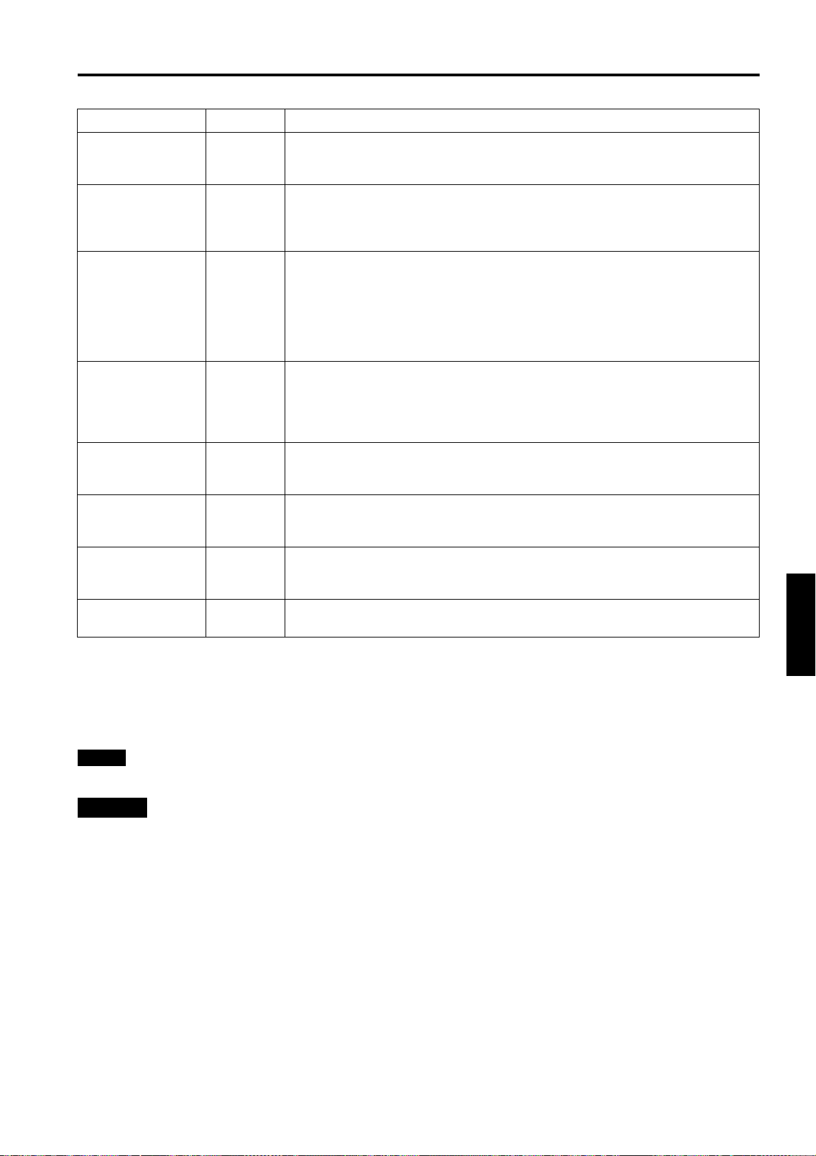
Adjustment item Button Adjustment content
Sets whether to clear the menu display automatically or not.
Menu display 2 or 3
Line display 2 or 3
Keystone ENTER
PC2 (BNC) 2 or 3
Right Left rev.
Top Bottom inv.
or
2
or
2
15sec* : Clears the display automatically in about 15 seconds.
ON : Does not automatically clear the menu display.
Sets whether to show the line display (Y/C, VIDEO, PC1, or PC2) on top right of the
screen or not when the VIDEO or PC button is pressed.
5sec* : Shows the line display for about 5 seconds.
OFF : Does not show the line display.
Press the ENTER button to enter the keystone submenu.
In the keystone submenu, press 2 or 3 to correct trapezoidal distortion of the
projected image. (–80 ↔ 0* ↔ +128)
To reset the keystone (trapezoidal distortion of the picture image) to the original
setting (factory set value: 0), press the PRESET button when the “Keystone”
submenu appears on the screen.
To exit the keystone submenu, press the ESCAPE button.
Sets the input signal source according to the device connected to the PC 2 terminals.
However, the input will be RGB irrespective of the PC signal setting.
RGB* : For a device with analog RGB, V, H/Cs signals
YP
Reverses image right-to-left.
OFF* : For the front method.
3
ON : For upside-down hanging from the ceiling.
Inverses image upside-down.
OFF* : For normal setup.
3
ON : For upside-down hanging from the ceiling.
: For a device with component (Y, B-Y, R-Y) or DTV-format (Y, PB, PR)
BPR
signals
Menu Operations
Sets the baud rate for transmission.
RS-232C [bps] 2 or 3
Sleep time [min]
* Factory set value
Press the ESCAPE button to return to the previous menu or press the MENU button
5
or
2
9600 : 9600 bps
19200* : 19200 bps
Sets the length of sleep time which automatically brings the projector into stand-by
3
state. You can select one of the sleep times: 15, 30, 60 and 0 (OFF*) minutes.
to exit the menu mode.
Note
• Refer to “Removing the Trapezoidal Distortion of the Image” on page 34 for more details about adjusting the keystone.
CAUTION
• Correctly set the “PC2 (BNC)” according to the device connected to the PC2 terminals. However, when the PC signal is
input, RGB input is used irrespective of which setting (YPBPR) is made.
ENGLISHDEUTSHFRANÇAISITALIANOESPAÑOL
53
Page 55
Menu Operations
Getting Information
You can get information on the input signal, accumulated used hours of light-source lamp, etc.
Press the MENU button.
1
The main menu appears on the screen.
Select “Information” with the cursor button 5555 or ∞∞∞∞.
2
The “Information” will be displayed in the main menu.
*No submenu can be selected.
Video main menu PC main menu
Menu
Image adj.
Setting
Color temp.
Options
Language
Information
Input
Switcher
Source
Lamp time
VIDEO
CH.0
NTSC
123 h
Menu
Image adj.
Setting
Color temp.
Options
Language
Information
Input
Switcher
Resolution
Frequency H
Frequency V
Lamp time
PC 1
CH.0
1280 1024
kHz
79.9
Hz
75
h
123
Input: Shows the terminal name selected by the VIDEO or PC button. (Y/C or VIDEO, or PC1 or PC2)
Switcher: This display currently has no meaning. This is reserved for future use. (“CH.0” is usually displayed to
indicate that it is not being used.)
Source: Shows the projected image’s type of video signal. (Video me nu mode)
Resolution: Shows the resolution of the video signal being received. (PC menu mode)
It may not be displayed correctly with some input signals.
Frequency H: Show s the horizontal frequency of the video signal being received. (PC menu mode)
Frequency V: Shows the vertical frequency of the video signal being received. (PC menu mode)
Lamp time: Accumulated us ed hours of the light-source lamp.
Press the MENU button to exit the menu mode.
3
54
Page 56
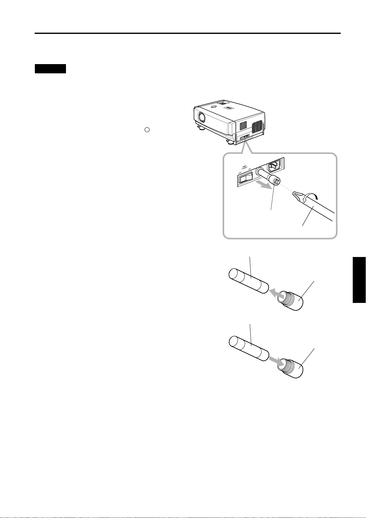
Replacing the Fuse
A fuse is used to protect the power source of the projector. If the fuse is blown, replace it. When the power switch is turned on
but no power is supplied to the projector, check the fuse. If there are any unclear points, contact the dealer where you
purchased your projector, or consult the Service center.
CAUTION
• When replacing the fuse, use the same rating and type (15A 250V). Otherwise, a fire may occur and/or the projector may be
damaged.
Turn off the main power switch and
1
disconnect the power cord from both
the projector and the wall outlet.
In stand-by state (the STAND BY indicator lights on),
place the MAIN POWER switch of OFF [ ] position.
Loosen the fuse holder to remove it.
2
To loosen the fuse holder, use a Philips screwdriver.
Remove the fuse from the fuse holder
3
you just removed.
Install the new fuse (not supplied) into
4
the fuse holder.
Reinstall the fuse holder into the
5
projector.
To reinstall the fuse holder, use a Philips screwdriver.
Fuse holder
Philips screwdriver
Fuse (15A, 250V)
Fuse holder
ENGLISHDEUTSHFRANÇAISITALIANOESPAÑOL
Fuse (15A, 250V)
Fuse holder
55
Page 57
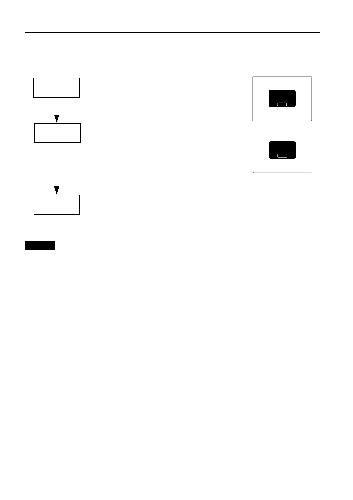
Replacing the Light-Source Lamp
The light-source lamp has a service life of approximately 1000 hours.
When the light-source lamp approaches the end of its service life, degradation progresses rapidly.
The LAMP indicator and the message on the screen warn you that replacement of the lamp is required, as follows:
Accumulated used hours
of the light-source lamp
• The LAMP indicator lights up on the proj e cto r.
900 hours
1000 hours
1010 hours
• On the screen, “Lamp replacement” appears in red.
To cancel this message, press the ESCAPE button.
• Arrange for a new light-source lamp or replace the lightsource lamp a little earlier.
* Every time the projector is turned on, the message appears.
• The LAMP indicator blinks on the projector.
• On the screen, “Warning Lamp replacement” appears in red
and the word “Warning” blinks.
Replace the light-source lamp.
To cancel this message, press the ESCAPE button. However,
the same message will appear every one hour.
* Only OPERATE button to stop the projector and the ESCAPE
button are operative.
* Once the projector is turned off, the projector does not turn on
unless the light-source lamp is replaced with new one.
• The projector is forcibly shut off.
* The projector does not turn on unless the light-source lamp is
replaced with new one.
Lamp replacement
ESCAPE
Warning
Lamp replacement
ESCAPE
Purchase a new light-source lamps (Part No. : BHL5003-SU) from the authorized dealer where you purchased the
projector, or consult the Service Center.
CAUTIONS
• If the projector is set up in a constricted place which is unsuitable for work, and if you perform replacement work there, this
could cause injury. Move the projector to a place large enough for work, and then replace the light-source lamp.
• Use a genuine product for the light-source lamp. If you use other than a genuine product, this could cause a malfunction.
Also, never use an old light-source lamp. This could cause marked degradation in performance or explode, possibly causing
the projector to malfunction or broken pieces to injure you.
• Do not replace the light-source lamp immediately after the projector has been used. The temperature of the light-source
lamp is still high and could cause a burn. Allow a cooling period of one hour or more before performing replacement.
• Before starting light-source lamp replacement work, turn off the MAIN POWER switch, and disconnect the power cord from
the wall outlet. If you perform the replacement work with the power cord connected, this could cause injury or electric shock.
• The light-source lamp used in this projector is a high pressure mercury lamp. Be careful when disposing of the light-source
lamp. If anything is unclear, please consult your dealer.
56
Page 58
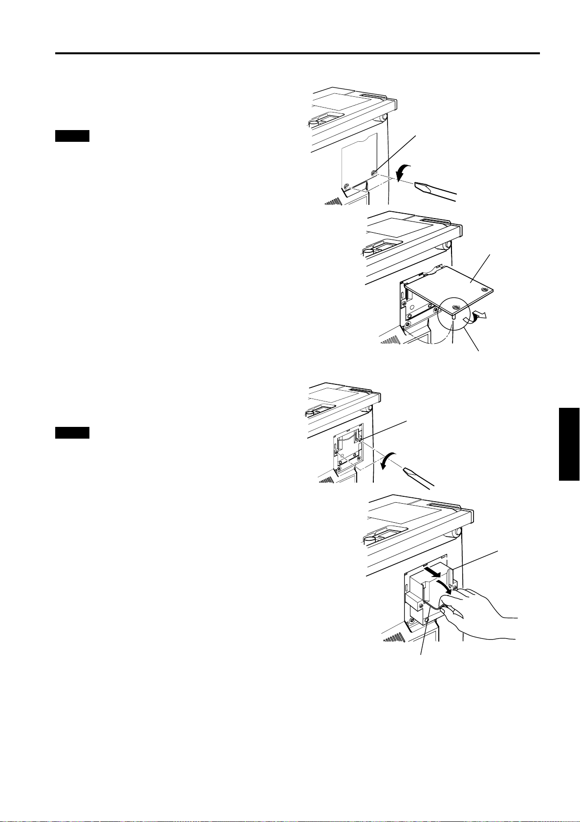
Replacing the Light-Source Lamp
■ Be sure that the power cord is unplugged from the wall outlet.
Remove the lamp-replacement opening
1
cover by loosening screws.
Loosen the two screws with a flat-end screwdriver.
Note
• The screws are fitted so that they do not come off the lamp-
replacement opening cover.
Screw
Lamp-replacement
opening cover
Loosen the screws, raise the handle,
2
and pull out the light-source lamp.
Loosen the two screws with a flat-end screwdriver.
Note
• The screws are fitted so that they do not come off the light-
source lamp.
Be careful not to damage
the claw.
Screw
ENGLISHDEUTSHFRANÇAISITALIANOESPAÑOL
Light-source lamp
Handle
(To be continued on the next page)
57
Page 59
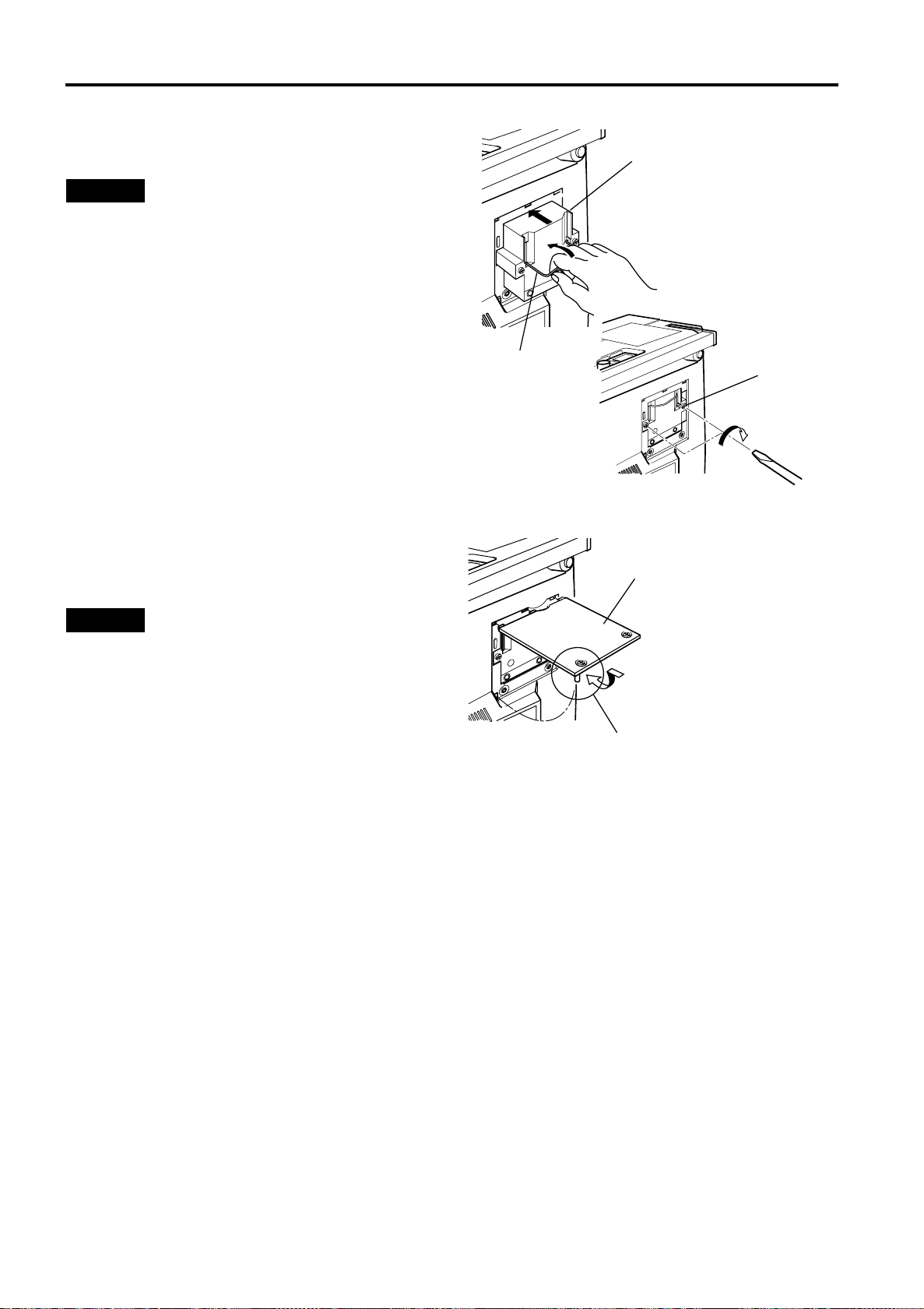
Replacing the Light-Source Lamp
Insert the new light-source lamp fully
3
inside and fasten the screws.
Fasten the two screws with a flat-end screwdriver.
CAUTION
• Do not touch the glass surface of the light-source lamp
directly with your hand as well as staining it. If you touch
with a bare hand, oils and other substances on your hand
may adhere to the lamp, possibly preventing it from
performing as specified and therefore giving a shortened
lamp life, a darkened screen, etc. To handle a new lightsource lamp, hold it by the plastic part. Never touch the
metal part or the front glass surface.
Light-source lamp
Handle
Screw
Replace the lamp-replacement opening
4
cover and fasten the screws.
Fasten the two screws with a flat-end screwdriver.
CAUTIONS
• Install the light-source lamp and close the lampreplacement opening cover correctly; otherwise, a safety
switch is activated to prevent the projector from operating.
• If the claw on the lamp-replacement opening cover is
damaged, the projector may not possibly operate. Then,
replace with a new lamp-replacement opening cover.
Reset the lamp use time.
5
Perform “Resetting the Lamp Use Time” on page 59.
Lamp-replacement
opening cover
Be careful not to
damage the claw.
58
Page 60
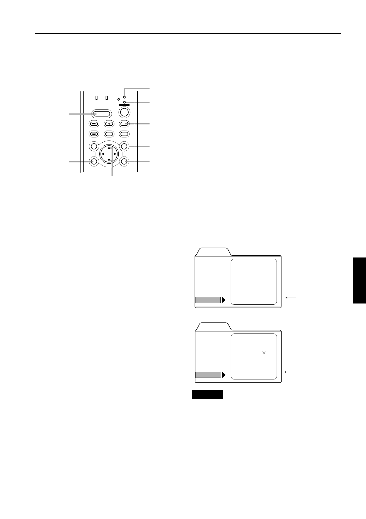
Replacing the Light-Source Lamp
■ Resetting the Lamp Use Time
After replacing with a new light-source lamp, reset the lamp-time counter inside the projector to clear the accumulate d lamp
time to zero (0). After resetting, a new count will start for the new light-source lamp.
Turn on the MAIN POWER switch to go
■ Projector’s button
1
into stand-by mode.
In stand-by mode, the STAND BY indicator on the
projector lights up.
Press the following buttons on the
2
projector, sequentially.
1
Momentary press the PC button.
2
Momentary press the ENTER button.
3
Momentary press the ESCAPE button.
4
Press and hold the HIDE button for two
seconds or more.
* During this sequence, the STAND BY and OPERATE
indicators alternately blink about every approx. 3
seconds. After completion of the sequence, the
STAND BY indicator alone stays on.
* Buttons must be pressed within 2 seconds of the
previous button.
* When you make a mistake in button operations, return
to the beginning of the sequence.
* To check the lamp time on the menu, press the MENU button
and select “Information” with the cursor button
The lamp use time is indicated in the item “Lamp time”.
Video main menu
Menu
Image adj.
Setting
Color temp.
Options
Language
Information
Input
Switcher
Source
Lamp time
VIDEO
CH.0
NTSC
123 h
or ∞.
5
Lamp time (0 h)
4
HIDE
button
3
ESCAPE
button
LAMP TEMP
HIDE
KEYSTONE VOLUME
PRESET
ESCAPE ENTER
STAND BY
OPERATE
PC
VIDEO
MENU
Cursor buttons 5/∞
STAND BY
indicator
OPERATE
indicator
1 PC
button
MENU
button
2 ENTER
button
ENGLISHDEUTSHFRANÇAISITALIANOESPAÑOL
PC main menu
Menu
Image adj.
Setting
Color temp.
Options
Language
Information
Input
Switcher
Resolution
Frequency H
Frequency V
Lamp time
PC 1
CH.0
1280 1024
kHz
79.9
Hz
75
h
123
Lamp time (0 h)
CAUTION
• Reset the lamp use time only when you have replaced with
a new light-source lamp. Never reset it during lamp life,
otherwise the replacement time may become unclear, and
lead to degraded performance or lamp explosion.
59
Page 61
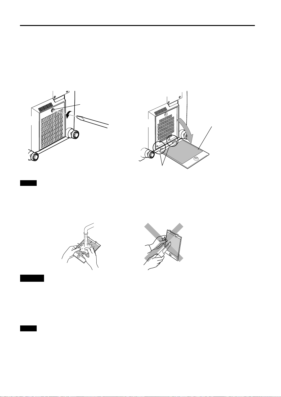
Cleaning and Replacing the Filter Cover
Clean the filter regularly. If the filter is heavily stained and does not clean, or if it is damaged, replace the filter with a new filter.
Otherwise, dirt may get inside and appear on the screen, preventing you from fully enjoying the video image. If dirt gets inside
or if you need information about the filter, consult authorized dealer where you purchased the projector or the nearest Service
Center.
Turn off the MAIN POWER switch.
1
After the projector goes into stand-by state with the STAND BY indicator on, turn off the MAIN POWER switch and pull
out the power cord from the projector and the wall outlet.
Remove the filter.
2
Loosen the screw with a flat-end screwdriver.
Screw
Filter
Be careful not to
damage the claws.
Notes
• The screw is fitted so that it does not come off the filter.
• If the filter is clogged with dirt, etc., the projector goes into an warning state (the OPERATE and STAND BY indicator blink.
etc.). Therefore regularly, clean the filter. For the warning indication, refer to page 64.
Clean the filter.
3
Clean the filter with a neutral detergent, wash it in water, and then dry it in the shade.
CAUTIONS
• Put on rubber gloves when using neutral detergent.
• After you have washed the filter in water, make sure the filter is completely dry before reinstalling it, otherwise an electric
shock or malfunction could occur.
• Do not clean the filter using a vacuum cleaner. Since the filter is soft, it may be sucked into the vacuum cleaner or damaged.
Reinstall the filter.
4
Fasten the screw with a flat-end screwdriver.
Notes
• Install the filter correctly. Otherwise, the projector does not operate. (Goes into an warning state (For the warning indication,
Refer to page 63).)
• If the filter’s claws (in particular the claw which is hidden behind the filter cover knob) are damaged, the projector may not
operate. Then, replace with a new filter.
60
Page 62
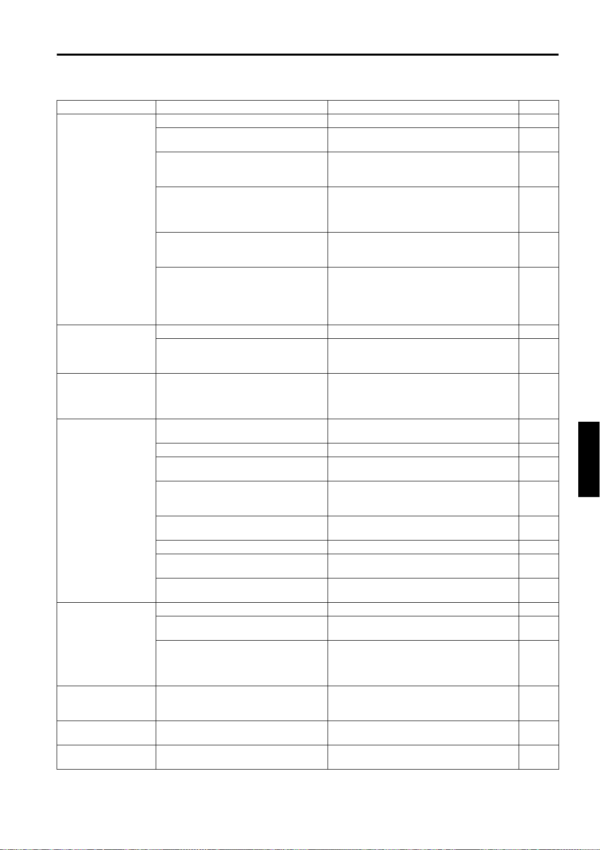
Troubleshooting
Solutions to common problems related to your projector are described here. If none of the solutions presented here solves the
problem, unplug the projector and consult an authorized dealer or Service Center.
Symptom Probable cause Corrective action Page
Power is not
supplied.
Light is not emitted,
or light level is low.
With power on,
operation starts but
stops in a few
minutes.
Video image does not
appear, or audio
sound does not
occur.
Video image dims. • Is focus adjusted correctly? • Adjust focus. 13, 33
Video image is
abnormally dark or
bright.
Video image freezes. • Was the FREEZE button on the
A part of image is
magnified.
• Is the power cord disconnected? • Insert the power cord (plug) firmly. 30
• Is the MAIN POWER switch turned
on?
• Is the fuse blown? • Turn off the MAIN POWER switch and
• Is the lamp-replacement opening cover
closed correctly?
• Is the filter closed correctly? • Turn off the MAIN POWER switch, fit the
• Has the lamp life expired? (Has the
lamp use time reached 1000 hours?)
• Is the lens cap removed? • Remove the lens cap. 30
• Is the lamp life near its end? • Check the lamp use time on the menu, and
• Is the air intake or exhaust area
blocked?
• Is the correct input selected? • Select the correct input with the VIDEO and
• Are devices connected correctly? •Connect devices correctly. 11, 22
• Are signals being supplied from the
connected devices?
• Are input signals (scanning frequency,
etc.) appropriate?
• Is the correct color system selected? • Set the color system to AUTO or to the
• Is brightness adjusted correctly? • Adjust brightness on the menu. 47
• Is volume set at minimum? • Adjust volume with the VOLUME +/–
• Are video and audio turned off by
pressing the HIDE button?
• Is distance too short or too long? • Set the projector at the correct distance. 18, 71,
• Are Tracking and Phase adjusted
correctly?
• Is picture quality (Brightness, etc.)
adjusted correctly?
remote control pressed?
• Was the DIGITAL ZOOM + button on
the remote control pressed?
• Turn on the MAIN POWER switch. 31
55
check the fuse.
If it is blown, replace it
• Turn off the MAIN POWER switch, close
the lamp-replacement opening cover
correctly, and turn on the MAIN POWER
switch again.
filter correctly, and turn on the MAIN
POWER switch again.
• Turn off the MAIN POWER switch, replace
with a new light-source lamp, and turn on
the MAIN POWER switch.
Reset the lamp use time after replacing with
a new lamp.
if the lamp life is near its end, arrange for a
replacement lamp, or replace a little earlier.
• Turn off the MAIN POWER switch, remove
any blocking objects, and turn on the MAIN
POWER switch again.
PC buttons.
• Set connected devices correctly. –
• Check if the signal is appropriate (scanning
frequency, etc.) and input the appropriate
signal.
correct dedicated color system.
buttons.
• Press the HIDE button to turn video and
audio on.
• If satisfactory results are not obtained by
pressing the QUICK ALIGN. button to
conduct quick alignment, adjust Tracking
and Phase on the menu.
• Adjust picture quality on the menu. 47
• Press the FREEZE button to release
freezing.
• Press the PRESET button to restore the
original video screen.
7, 31, 56
7, 31, 60
31, 56,
59
54, 56
6, 7, 31
9, 12, 13
22, 23
44
10, 13,
33
10, 13,
34
72
13, 35,
46
13, 36
13, 36
ENGLISHDEUTSHFRANÇAISITALIANOESPAÑOL
61
Page 63
Troubleshooting
Symptom Probable cause Corrective action Page
Color is poor or
unstable.
The upper part of the
video image bows or
distorts.
Video image and
audio sound
suddenly go out.
Remote control unit
does not work.
* This device uses a computer. External noise may cause it to malfunction. If this happens, turn the power off, remove the
electric plug from the wall outlet. Then insert the electric plug back into the wall outlet, turn the power back on and check the
operation.
• Is picture quality (color density, etc.)
adjusted correctly?
• Is the correct color system selected? • Set the color system to AUTO or to the
• Are signals (scanning frequency, etc.)
of the connected devices appropriate?
• Is the PC2 input terminal being used? • When the PC2 input terminal is being use,
• While computer system signal is input,
isn’t a sync signal for composite sync
(Cs) or G on sync being input?
• Isn’t signal with much jitter or skew
distortion being input from a video
deck?
• Are video picture and audio turned off
by pressing the HIDE button?
• Are batteries installed correctly? • Match the polarities of batteries correctly (+
• Are batteries exhausted? •Replace with new batteries. 14
• Is there a shielding object between the
remote control unit and the remote
sensor?
• Is the distance too long? • Use the remote control unit at a nearer
• Is either side of remote cable
disconnected?
• Adjust picture quality on the menu. 47
44
correct dedicated color system.
• Check if the signal is appropriate (scanning
frequency, etc.), and input the appropriate
signal.
“PC 2(BNC)” must be selected from the
menu options. Set it correctly with the input
signal.
• Input separate sync signals for vertical sync
(V) and horizontal sync (H) signals.
• Input signals with little jitter or distortion.
Use a TBC or a device with a built-in TBC.
• Turn on video picture and audio by pressing
the HIDE button.
to + and – to –).
• Remove any shielding objects. 20
point.
• Firmly insert the remote cable when using
the remote control unit as the wired one.
22
11, 52
11, 28
10, 13,
34
14
20
20
–
■ When warning indication is shown by the blinking indicators:
The warning status will be notified by the combination lighting of the projector’s indicators.
For the warning contents and the action to be taken, refer to “Warning Indication” on page 63.
Maintenance
■
• Stains on the cabinet
These should be wiped off with a soft cloth. If the cabinet is heavily stained, wipe it with a cloth soaked in water-diluted
neutral detergent and wring well, then wipe clean with a dry cloth.
• Since the cabinet may deteriorate in quality, become damaged, or show paint peeled, note the following:
– Do not wipe with rough cloth.
– Do not wipe vigorously.
– Do not wipe with thinner or benzene.
– Do not apply any volatile substance such as insecticides.
– Do not allow any rubber or vinyl article to remain in contact with the cabinet for a long time.
• Stains on the lens
These should be cleaned off with commercially available lens blowers or lens cleaning paper (for cleaning glasses and
cameras).
Do not use liquid cleaning agents. This could cause the surface coating to be removed.
Do not rub, scratch or hit the lens as its surface is prone to damage.
62
Page 64
Warning Indication
If something abnormal has occurred with the projector, the warning status will be indicated by the combination of lighting the
indicators on the control panel as shown in the following table. Then, the projector automatically stops projection and runs the
cooling fan for about 120 seconds.
Warning indication table:
No.
1 Blink Blink
2 Blink Blink
3 Blink Blink Circuit operation is abnormal.
4 Blink Blink The filter is displaced.
5 Blink The internal temperature is too high. (Sensor 1)
6 Blink Blink The internal temperature is too high. (Sensor 2)
7 Blink Blink Blink Blink The cooling fan has stopped (locked).
* For individual indicator lighting, refer to page 56.
■
Action to be taken for warning indication
LAMP TEMP STAND BY OPERATE
Indicator
Warning content
The light-source lamp does not light and projection
is not made.
The light-source lamp has suddenly gone off during
projecting an image.
Stopping the projector:
After the cooling fan has stopped, take the following action.
No. 1 : Chek that the cover for replacing the light-source lamp and the front panel are securely attached, and then, press
the OPERATE button for one second or more to turn on the projector for retrying.
No. 2 : Chek that the cover for replacing the light-source lamp and the front panel are securely attached, and then, press
the OPERATE button for one second or more to turn on the projector for retrying.
No. 3 : Press the OPERATE button for one second or more to turn on the projector for retrying.
Nos. 4-7 : Follow the next steps.
1. Turn off the MAIN POWER switch and unplug the power cord from the wall outlet.
2. Take an action according to the number.
No. 4 : Set the filter in place.Then, leave the projector until it cools down.
No. 5 : Check that nothing is blocking the air inlet nor outlet, and wait until the inside cools down.
No. 6 : Check that nothing is blocking the air inlet nor outlet, and wait until the inside cools down.
No. 7 : Leave the projector until it cools down.
3. Plug in the power cord again, turn on the MAIN POWER switch, and press the OPERATE button for one second or
more to turn on the projector for retrying.
Retrying operation:
Plug in the power cord again and operate the projector.
If the same warning indication is observed again, after the cooling fan has stopped, turn off the MAIN POWER switch, unplug
the power cord, and call your dealer for repair.
ENGLISHDEUTSHFRANÇAISITALIANOESPAÑOL
63
Page 65
Warning Messages
The following shows the warning messages that can be displayed on the screen. When a warning message is displayed, take
the corrective action described here.
Message Cause Corrective action Page
PC 1
No Input
• No device is connected to the
input terminal.
• The terminal is connected but no
signal is output from the
connected device.
* The selected input mode (input
terminal) name is shown in the
first line of the massage.
• Connect a device to the selected
terminal.
• Operate the connected device
and output a signal.
9, 11,
24 ~ 29,
32
PC 1
Frequency of image signal is out of range.
PC 1
No image signal is shown for this type.
FREEZE
• The frequency of the input video
signal is out of range.
• The selected input mode (input
terminal) name is shown in the
first line of the message.
• Though the frequency of the input
video signal is within the
acceptable range, other items
such as resolution are out of the
projector’s specifications.
• The selected input mode (input
terminal) name is shown in the
first line of the message.
• When the FREEZE button is
pressed, this message appears
for a few seconds.
• When a button not acceptable is
pressed during freezing, this
message appears for a few
seconds to notify that the image is
being frozen.
• Input the video signals whose
frequency is within the projector’s
specifications.
• Input the video signals that
satisfies the projector’s
specifications.
• To release freezing, press the
FREEZE button on the remote
control.
22, 23,
66
22, 23,
66
13, 36
64
FREEZE
• When the FREEZE button is
pressed for the video signals that
cannot be frozen (UXGA, etc.),
this message appears for a few
seconds to notify that the image
cannot be frozen.
* To forcibly clear the message,
press the ESCAPE button.
• Freeze function does not work for
the inputted video signals.
To use this function, input the
video signals that can be frozen.
13, 36
Page 66
Warning Messages
Message Cause Corrective action Page
D.ZOOM
• When the DIGITAL ZOOM button
is pressed for the video signals
that cannot be zoomed (UXGA,
etc.), this message appears for a
few seconds to notify that the
image cannot be digitally zoomed.
* To forcibly clear the message,
press the ESCAPE button.
• Digital-zoom function does not
work for the inputted video
signals.
To use the this function, input the
video signals that can be digitally
zoomed.
12, 36
Lamp replacement
ESCAPE
Warning
Lamp replacement
ESCAPE
• The accumulated lamp use time
reaches 900 hours.
* Every time the projector is turned
on, this message appears on the
screen.
• The accumulated lamp use time
reaches 1000 hours.
The word “Warning” blinks.
* The message can be cleared by
pressing the ESCAPE button.
However, the same message will
appear every one hour.
* Once the projector is turned off,
the projector does not turn on
unless the light-source lamp is
replaced with new one.
* When the accumulated lamp use
time reaches 1010 hours, the
projector is forcibly shut off.
• Press the ESCAPE button to
clear the massage.
(This display can be cleared with
the MENU button or other
buttons.)
• Arrange for a new light-source
lamp or replace the light-source
lamp a little earlier.
• Replace the light-source lamp
and reset the lamp use time.
10, 12,
54 ,56
56 ~ 59
ENGLISHDEUTSHFRANÇAISITALIANOESPAÑOL
Memo
The message display language corresponds to the menu display language setting. This is set to “English (English)” when the
projector is bought. The display language can be selected from 6 languages. (Refer to page 45.) However, the input mode
(PC1, PC2,Y/C, VIDEO) and button indications (FREEZE, D.ZOOM, ESCAPE) are only displayed in English irrespective of
the display language setting.
The language settings in the section are explained in “English”.
65
Page 67

Specifications
■
Optical mechanism system
• Projection method D-ILA™ (Direct Drive Image Light Amplifier) method
• D-ILA™ device 0.9" (2.3 cm) measured diagonally (1365 pixels × 1024 pixels) × 3
• Projecting lens GL-M2910G: 1:1
• Screen size GL-M2910G: Refer to page 71.
• Projection distance GL-M2910G: Refer to page 71.
• Light-source lamp 550 W xenon lamp
■
Electrical system
• Color system NTSC, NTSC4.43, PAL, SECAM (Automatic switching / manual switching)
• Resolution 1365 dots × 1024 dots (S-XGA full resolution, during RGB input)
• Scanning frequency Horizontal frequency :15 kHz ~ 105 kHz
• Audio power output 1 W (monaural), 1-
(Reflective-type active-matrix method)
(Total number of pixels : 4,193,280)
GL-M2915SG: 1.5:1 (with ±2% zooming/shift function)
GL-M2920ZG:× 1.5 zoom lens (2:1 to 3:1) (zooming function)
GL-M2930SZG:× 1.9 zoom lens (2.9 to 5.5:1) (zooming/shift function)
GL-M2915SG: Refer to page 71.
GL-M2920ZG: Refer to page 72.
GL-M2930SZG: Refer to page 72.
GL-M2915SG: Refer to page 71.
GL-M2920ZG: Refer to page 72.
GL-M2930SZG: Refer to page 72.
1000 TV lines (Horizontal resolution, aspect ratio 4 : 3, during video input)
Vertical frequency :50 Hz ~ 100 Hz
5
/8" (4 cm) round type micro-speaker × 1
■
Input terminals
[AV IN]
• Y/C 1-line, mini-DIN 4 pin × 1 (for S-video)
• VIDEO 1-line, BNC × 1 (for composite video)
• AUDIO 1-line, RCA pin × 1 (for Y/C or VIDEO IN)
[PC 1]
• R, G, B, H, V 1-line, D-sub 3-row 15 pin × 1 (for computer)
[PC 2]
1-line, BNC × 5 (for computer, DTV or video)
• Y, B-Y, R-Y Component (Y, B-Y, R-Y) signal
, P
B
• Y, P
• R, B, G Analog RGB signal
• H/Cs
• PC AUDIO 1-line, mini-jack × 1 (for PC 1 or PC 2)
[CONTROL]
• RS-232C 1-line, D-sub 9-pin × 1
• REMOTE 1-line, stereo mini-jack × 1
R
, V Horizontal (H) sync/composite (CS) sync, Vertical (V) sync signal
DTV-format (Y, PB, PR) signal
* RS-232C-interface specified control terminal for controlling this projector with a personal
computer.
* Remote terminal for connecting with the remote control unit.
■
Output terminal
• PC OUT 1-line, D-sub 3-row 15-pin × 1 (output for display monitor)
66
Page 68
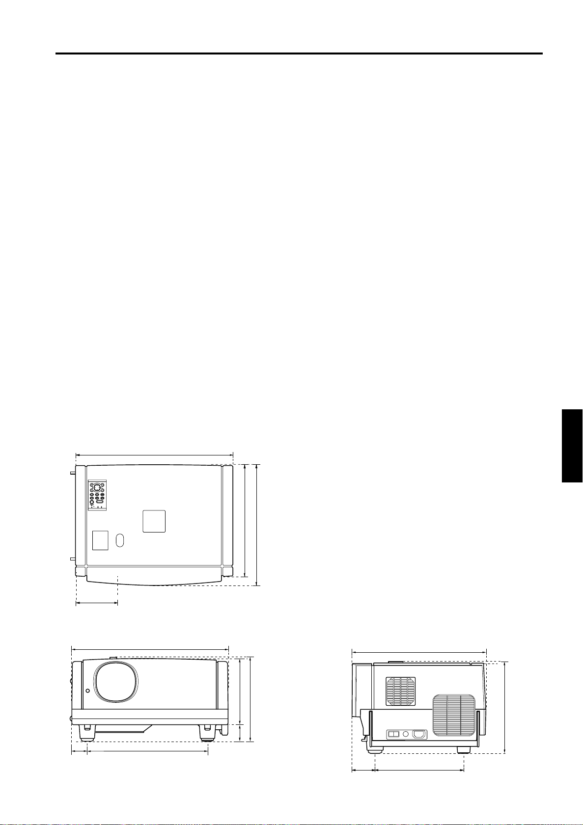
Specifications
General
■
• Power requirements 120 V AC, 60 Hz
• Power consumption 9 A
• Allowable operation
temperature
• Allowable relative
humidity
• Allowable storage
temperature
• Dimensions
• Weight Approx. 34.32 lbs. (Approx. 15.6 k )
• Accessories (Refer to page 5.)
* Design and specifications are subject to change without notice.
* D-ILA devices are manufactured with a very high-precision technology, allowing 99.99% of the pixels to be effective. Only
0.01% or less of the pixels are missing or always on.
* For easy understanding, pictures and illustrations maybe emphasized, composed or have omissions and may be more or
less different from actual products.
* TRADEMARKS
D-ILA is a trademark of Victor Company of Japan, Limited.
IBM and IBM PC are registered trademarks of International Business Machines Corporation. Macintosh is a registered
trademarks of Apple Computer, Inc.
VESA is a trademark of the non-profit organization Video Electronics Standards Association.
All other product names mentioned herein are used for identification purposes only, and may be the trademarks or
registered trademarks of their respective companies.
41°F to 95°F (+ 5°C to + 35°C)
20% to 80% (no condensation)
14°F to 140°F (– 10°C to + 60°C)
Approx. 20" × 10-
1
/2" × 15-1/2" (Approx. 505 mm × 265 mm × 393 mm)
[Carrying band, Excluding protrusions]
(Width × Height × Depth)
Outside dimensions
■ Top
20 (505)
ESCAPE ENTER
MENU
PRESET
VIDEO
KEYSTONE VOLUME
PC
HIDE
OPERATE
LAMP TEMP
STAND BY
5-1/4 (133)
■ Front ■ Side
20 (505)
8
/
1
2-
(212)
8
/
3
8-
53)
(
*2
/8 (369 )
5
14-
(265)
2
/
1
10-
/2 (393)
1
15-
15-1/2 (
393)
Unit: inch (mm)
&'()*
&()*
(265)
2
/
1
10-
ENGLISHDEUTSHFRANÇAISITALIANOESPAÑOL
2-1/8
(
52)
15-1/2 (392)
2-7/
(
70)
8
10-1/8 (
256)
67
Page 69
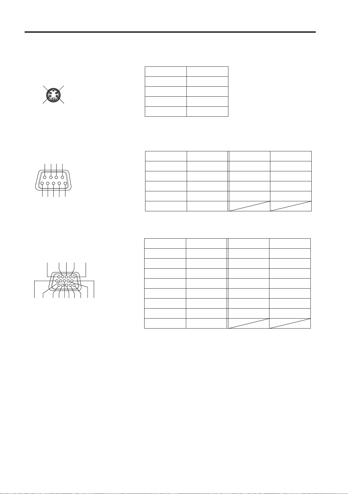
Specifications
Pin assignment (Specifications for terminals)
■ Y/C terminal
Pin number Signal name
34
1 GND (Y)
2 G ND (C)
2
1
■ RS-232C terminal
6
7189
5
2
3
4
■ PC1 terminal/PC OUT terminal
11
121314
15
3Y
4C
Pin number Signal name Pin number Signal name
1N/C6N/C
2RD7N/C
3 TD8N/C
4N/C9N/C
5GND
Pin number Signal name Pin number Signal name
1Red9N/C
2 Green 10 GND (SYNC)
3 Blue 11 GND
4N/C12N/C
5N/C13H.SYNC
7
6
3
1
8910
2
5
4
6 GND (Red) 14 V.SYNC
7 GND (Green) 15 N/C
8 GND (Blue)
68
Page 70
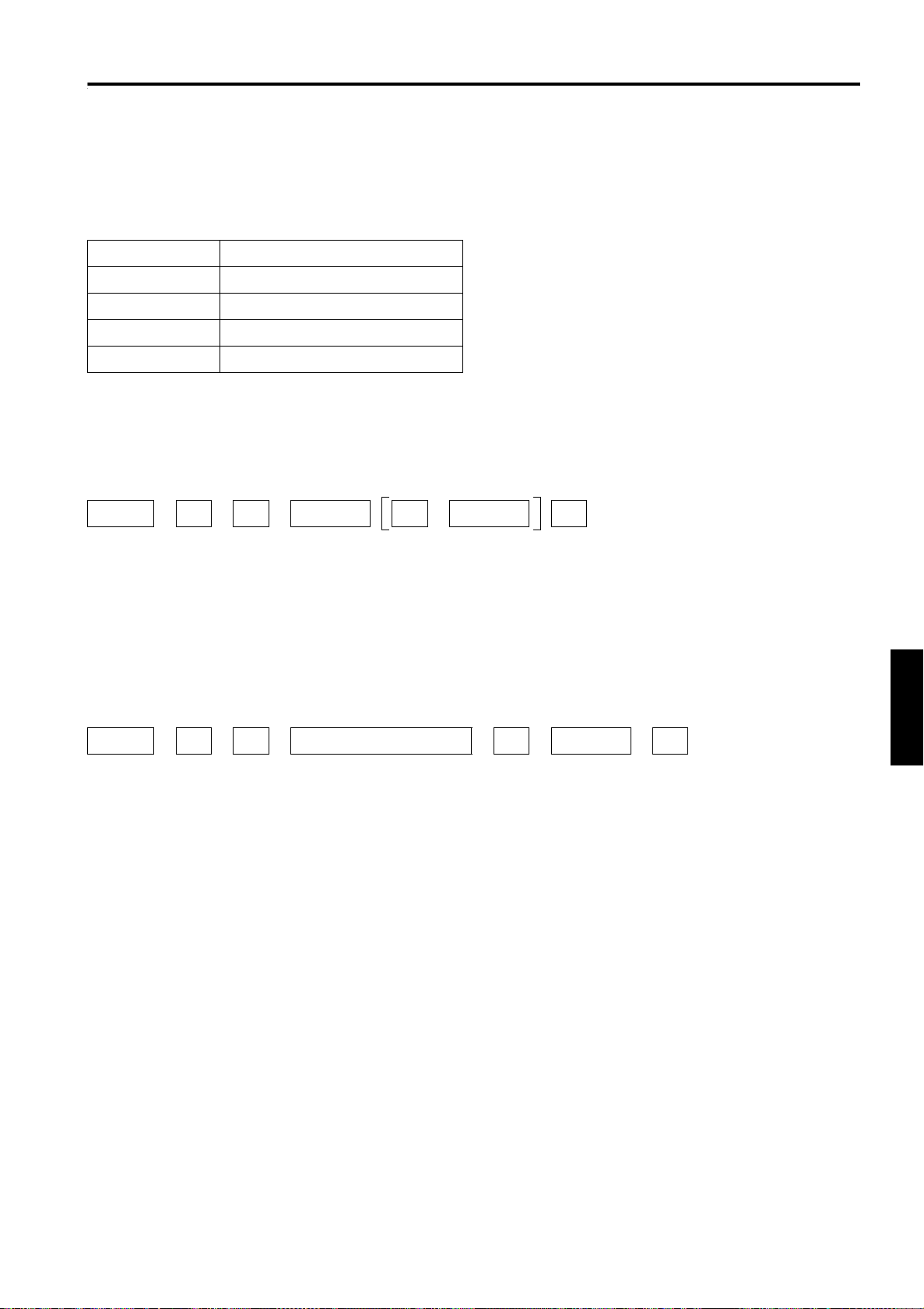
RS-232C external control
By connecting a computer to the RS-232C terminal, you can control the projector. Use a reverse connection cable as the RS232C connection cable.
The commands to control the projector and the response data against the received commands are explained here.
For further information, please consult the dealer where you purchased your projector or consult the Service Center.
1. Communication Specifications
The communication specifications are as follows:
Baud rate 9600bps / 19200bps*
Data length 8 bits
Parity None
Stop bit 1 bit
Flow control None
* Factory set value. To change the value, refer to “Setting and Adjusting Other Functions (OPTIONS)” on page 52.
2. Command Format
2-1. Command data format (from the computer to the projector)
When sending a control command, use the following data format.
Header ID SP Command SP Parameter CR
Header: Designa tes the head of data and the kind of data.
“!” (21h): Control command to the projector
“?” (3Fh): Query to the projector (Asking command)
ID: “1” (fixed)
SP: Designates the delimiter for ID, Command, and Parameter. (20h)
CR: Designates the terminal of the data. (0Dh)
* [ ] is not necessary when Asking command.
2-2. Response data format (from the projector to the computer)
Upon executing the received control command, the projector sends back the following response data to the computer.
Header ID SP Normal Termination Status SP Parameter CR
Header: Designates the head of data.
“@” (40h): Fetches data from the projector.
ID: “1” (fixed)
SP: Designates the delimiter for ID, Command, and Parameter (20h)
Normal Termination Status: “0” (30h)
CR: Designates the terminal of the data (0Dh)
ENGLISHDEUTSHFRANÇAISITALIANOESPAÑOL
69
Page 71
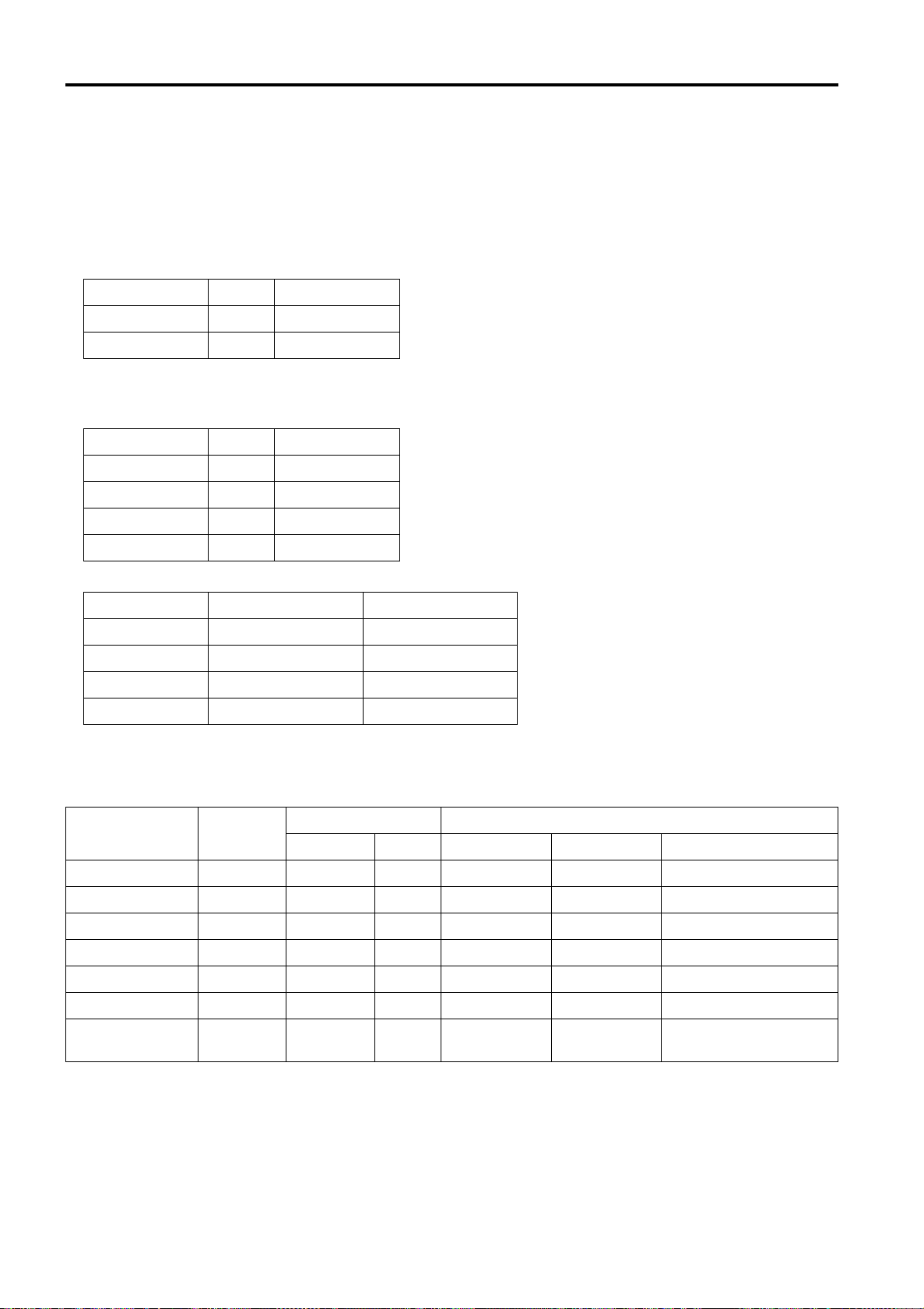
RS-232C external control
2-3 Parameters used for the data format
The following three kinds of parameters are prepared for the control command and response data.
(1) Numeric value
Designates the 2-byte hexadecimal value with the sign as the 4-digit (byte) characters.
Designation allowable range: “8000” to “7FFF”
(2) ON/OFF
Designates the status (ON/OFF) of the projector, such as POWER and HIDE.
Character Hex. Meaning
“0” 30 OFF
“1” 31 ON
(3) Special parameters
Input switching parameters:
Character Hex. Meaning
“0” 30 Y/C
“1” 31 VIDEO
“3” 33 PC1
“4” 34 PC2
Operation mode parameters:
Character Hex. Meaning
“0000” 30h, 30h, 30h, 30h Stand-by mode
“0001” 30h, 30h, 30h, 31h Power-on mode
“0002” 30h, 30h, 30h, 32h Cool-down mode
“0004” 30h, 30h, 30h, 34h Warning mode
3. Control command table
The control commands that can be sent from the computer are as follows:
Function Command
OPERATE U0F – – – ✓ –
HIDE U00 ✓ –– ✓ –
Right Left rev. U17 ✓ –– ✓ –
Top Bottom inv. U18 ✓ –– ✓ –
Keystone U40 ✓ – ✓ ––
Input U1A ✓ – – – Y/C, VIDEO, PC1, PC2
Operation mode Z03 ✓✓ ––
Asking Kind of data
Power ON ELSE Numeric Value ON/OFF Special Data
Stand-by, Power-on,
Cool-down, Warning
* Keystone: Numeric value can range from “FF80” to “0080”
* Operation mode: Only Asking command is possible
70
Page 72
Appendix
■ Relationship between Projection Distances and Projection Screen Sizes
Notes
• The relationship between the projection distances and projection screen sizes differs depending on the lens unit (optional)
you are using.
• The projection distance and projection screen sizes listed here are only for a guide. Use them as reference when setting the
projector.
For lens unit GL-M2910G (1:1):
Projection screen size
(Diagonal length)
36.7" (approx. 93.2 cm) --- 2.53 (0.77)
40" (approx. 101.6 cm) 2.53 (0.77) 2.7 6 (0.84)
50" (approx. 127.0 cm) 3.18 (0.97) 3.4 8 (1.06)
60" (approx. 152.4 cm) 3.84 (1.17) 4.2 0 (1.28)
70" (approx. 177.8 cm) 4.53 (1.38) 4.9 5 (1.51)
80" (approx. 203.2 cm) 5.18 (1.58) 5.6 8 (1.73)
90" (approx. 228.6 cm) 5.87 (1.79) 6.4 0 (1.95)
100" (approx. 254.0 cm) 6.53 (1.99) 7.12 (2.17)
110" (approx. 279.4 cm) 7.22 (2.20) 7.87 (2.40)
120" (approx. 304.8 cm) 7.87 (2.40) 8.60 (2.62)
130" (approx. 330.2 cm) 8.53 (2.60) 9.32 (2.84)
140" (approx. 355.6 cm) 9.22 (2.81) 10.04 (3.06)
150" (approx. 381.0 cm) 9.88 (3.01) 10.79 (3.29)
160" (approx. 406.4 cm) 10.56 (3.22) 11.52 (3.51)
170" (approx. 431.8 cm) 11.22 (3.42) 12.24 (3.73)
180" (approx. 457.2 cm) 11.88 (3.62) 12.96 (3.95)
190" (approx. 482.6 cm) 12.57 (3.83) 13.68 (4.17)
200" (approx. 508.0 cm) 13.22 (4.03) ---
For lens unit GL-M2915SG (1.5:1):
Projection screen size
(Diagonal length)
55" (approx. 139.7 cm) --- 6.00 (1.83)
60" (approx. 152.4 cm) 5.77 (1.76) 6.3 0 (1.92)
65" (approx. 165.1 cm) 6.27 (1.91) 6.8 2 (2.08)
70" (approx. 177.8 cm) 6.76 (2.06) 7.3 8 (2.25)
75" (approx. 190.5 cm) 7.28 (2.22) 7.9 1 (2.41)
80" (approx. 203.2 cm) 7.78 (2.37) 8.4 6 (2.58)
85" (approx. 215.9 cm) 8.27 (2.52) 9.0 2 (2.75)
90" (approx. 228.6 cm) 8.76 (2.67) 9.5 5 (2.91)
95" (approx. 241.3 cm) 9.28 (2.83) 10.10 (3.08)
100" (approx. 254.0 cm) 9.78 (2.98) 10.63 (3.24)
105" (approx. 266.7 cm) 10.27 (3.13) 11.19 (3.41)
110" (approx. 279.4 cm) 10.76 (3.28) 11.75 (3.58)
115" (approx. 292.1 cm) 11.25 (3.43) 12.27 (3.74)
120" (approx. 304.8 cm) 11.78 (3.59) 12.83 (3.91)
125" (approx. 317.5 cm) 12.27 (3.74) 13.35 (4.07)
130" (approx. 330.2 cm) 12.76 (3.89) 13.91 (4.24)
135" (approx. 342.9 cm) 13.25 (4.04) 14.44 (4.40)
140" (approx. 355.6 cm) 13.75 (4.19) --145" (approx. 368.3 cm) 14.27 (4.35) --150" (approx. 381.0 cm) 14.76 (4.50) ---
Approximate projection distance unit: ft (m)
For 4:3 aspect-ratio screens For 16:9 aspect-ration screens
Approximate projection distance unit: ft (m)
For 4:3 aspect-ratio screens For 16:9 aspect-ration screens
ENGLISHDEUTSHFRANÇAISITALIANOESPAÑOL
71
Page 73
Appendix
For lens unit GL-M2920ZG (2 to 3:1):
Projection screen size
(Diagonal length)
40" (approx. 101.6 cm) --------- --------- --------- 8.53 (2.60)
42" (approx. 106.7 cm) --------- 8.23 (2.51) --------- 9.96 (2.73)
50" (approx. 127.0 cm) --------- 9.74 (2.97) --------- 10.60 (3.23)
60" (approx. 152.4 cm) --------- 11.65 (3.55) 8.50 (2.59) 12.66 (3.86)
70" (approx. 177.8 cm) 9.09 (2.77) 13.55 (4.13) 9.84 (3.00) 14.73 (4.49)
80" (approx. 203.2 cm) 10.33 (3.15) 15.42 (4.70) 11.22 (3.42) 16.80 (5.12 )
100" (approx. 254.0 cm) 12.83 (3.91) 19.23 (5.86) 13.94 (4.25) 20.90 (6.37)
150" (approx. 381.0 cm) 19.09 (5.82) 28.71 (8.75) 20.77 (6.33) 31.23 (9.52)
200" (approx. 508.0 cm) 25.33 (7.72) 38.16 (11.63) 27.59 (8.41) 41.54 (12.66)
240" (approx. 609.6 cm) 30.35 (9.25) 45.73 (13.94) 33.04 (10.07) 49.80 (15.18)
250" (approx. 635.0 cm) 31.59 (9.63) 47.64 (14.52) 34.38 (10.48) 51.87 (15.81)
300" (approx. 762.0 cm) 37.86 (11.54) 57.09 (17.40) 41.21 (12.56) 62.17 (18.95)
310" (approx. 787.4 cm) 39.11 (11.92) 58.99 (17.98) 42.59 (12.98) 64.24 (19.58)
320" (approx. 812.8 cm) 40.35 (12.30) 60.89 (18.56) 43.93 (13.39) --------330" (approx. 838.2 cm) 41.60 (12.68) 62.76 (19.13) 45.31 (13.81) --------340" (approx. 863.6 cm) 42.85 (13.06) 64.67 (19.71) 46.65 (14.22) --------350" (approx. 889.0 cm) 44.09 (13.44) --------- 48.03 (14.64) ---------
400" (approx. 1016.0 cm) 50.36 (15.35) --------- 54.86 (16.72) --------450" (approx. 1143.0 cm) 56.63 (17.26) --------- 61.65 (18.79) --------470" (approx. 1193.8 cm) 59.12 (18.02) --------- 64.37 (19.62) --------480" (approx. 1219.2 cm) 60.37 (18.40) --------- --------- --------500" (approx. 1270.0 cm) 62.89 (19.17) --------- --------- --------521" (approx. 1323.3 cm) 65.52 (19.97) --------- --------- ---------
Approximate projection distance unit: ft (m)
For 4:3 aspect-ratio screens For 16:9 aspect-ration screens
Wide end Tele end Wide end Tele end
For lens unit GL-M2930SZG (2.9 to 5.5:1):
Projection screen size
(Diagonal length)
Wide end Tele end Wide end Tele end
40" (approx. 101.6 cm) --------- 14.83 (4.52) --------- 16.11 (4.91)
50" (approx. 127.0 cm) --------- 18.44 (5.62) --------- 20.05 (6.11)
60" (approx. 152.4 cm) --------- 22.05 (6.72) --------- 23.98 (7.31)
70" (approx. 177.8 cm) --------- 25.66 (7.82) 14.83 (4.52) 27.92 (8.51)
80" (approx. 203.2 cm) 15.55 (4.74) 29.30 (8.93) 16.93 (5.16) 31.86 (9.71 )
100" (approx. 254.0 cm) 19.36 (5.90) 36.52 (11.13) 21.06 (6.42) 39.76 (12.12)
150" (approx. 381.0 cm) 28.87 (8.80) 54.59 (16.64) 31.43 (9.58) 59.45 (18.12)
200" (approx. 508.0 cm) 38.39 (11.70) 72.67 (22.15) 41.77 (12.73) 79.17 (24.13)
240" (approx. 609.6 cm) 45.96 (14.01) 87.14 (26.56) 50.07 (15.26) 94.91 (28.93)
250" (approx. 635.0 cm) 47.86 (14.59) 90.78 (27.67) 52.13 (15.89) --------260" (approx. 660.4 cm) 49.77 (15.17) 94.39 (28.77) 54.20 (16.52) --------270" (approx. 685.8 cm) 51.67 (15.75) 97.99 (29.87) 56.27 (17.15) --------280" (approx. 711.2 cm) 53.58 (16.33) --------- 58.33 (17.78) --------300" (approx. 762.0 cm) 57.38 (17.49) --------- 62.50 (19.05) --------350" (approx. 889.0 cm) 66.90 (20.39) --------- 72.83 (22.20) ---------
400" (approx. 1016.0 cm) 76.41 (23.29) --------- 83.20 (25.36) --------470" (approx. 1193.8 cm) 89.70 (27.34) --------- 97.70 (29.78) --------480" (approx. 1219.2 cm) 91.60 (27.92) --------- --------- --------500" (approx. 1270.0 cm) 95.41 (29.08) --------- --------- --------510" (approx. 1295.4 cm) 97.31 (29.66) --------- --------- ---------
Approximate projection distance unit: ft(m)
For 4:3 aspect-ratio screens For 16:9 aspect-ration screens
72
 Loading...