

Page 1
SERVICE MANUAL
COMPACT COMPONENT SYSTEM
MB51520066
MX-DK1US,MX-DK1UW,MX-DK1UG,MX-DK1UN,
MX-DK3US,MX-DK3UW,MX-DK3UG,MX-DK3UN,MX-DK15UN
CA-MXDK3 SP-MXDK3FSP-MXDK3F
SP-MXDK1F SP-MXDK1F
Lead free solder used in the board (material : Sn-Ag-Cu, melting point : 219 Centigrade)
CA-MXDK1
CA-MXDK15SP-MXDK15F SP-MXDK15F
SP-MXDK3W
TABLE OF CONTENTS
1 PRECAUTION. . . . . . . . . . . . . . . . . . . . . . . . . . . . . . . . . . . . . . . . . . . . . . . . . . . . . . . . . . . . . . . . . . . . . . . . . 1-4
2 SPECIFIC SERVICE INSTRUCTIONS . . . . . . . . . . . . . . . . . . . . . . . . . . . . . . . . . . . . . . . . . . . . . . . . . . . . . . 1-7
3 DISASSEMBLY . . . . . . . . . . . . . . . . . . . . . . . . . . . . . . . . . . . . . . . . . . . . . . . . . . . . . . . . . . . . . . . . . . . . . . . 1-8
4 ADJUSTMENT . . . . . . . . . . . . . . . . . . . . . . . . . . . . . . . . . . . . . . . . . . . . . . . . . . . . . . . . . . . . . . . . . . . . . . . 1-19
5 TROUBLESHOOTING . . . . . . . . . . . . . . . . . . . . . . . . . . . . . . . . . . . . . . . . . . . . . . . . . . . . . . . . . . . . . . . . . 1-21
COPYRIGHT © 2006 Victor Company of Japan, Limited
No.MB515
2006/6
Page 2
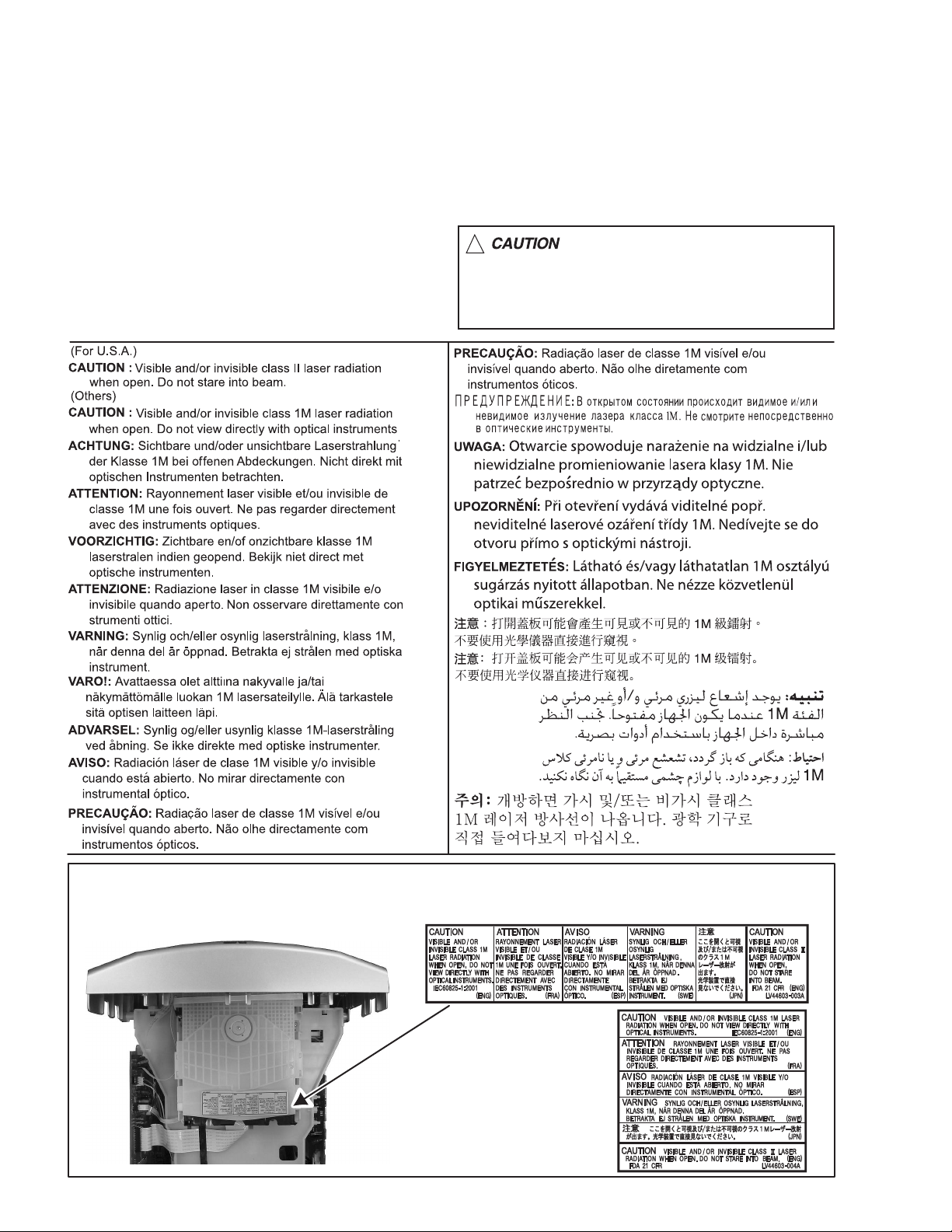
1.8 Important for laser products
1.CLASS 1 LASER PRODUCT
2.CAUTION :
(For U.S.A.) Visible and/or invisible class II laser radiation
when open. Do not stare into beam.
(Others) Visible and/or invisible class 1M laser radiation
when open. Do not view directly with optical instruments.
3.CAUTION : Visible and/or invisible laser radiation when
open and inter lock failed or defeated. Avoid direct
exposure to beam.
4.CAUTION : This laser product uses visible and/or invisible
laser radiation and is equipped with safety switches which
prevent emission of radiation when the drawer is open and
the safety interlocks have failed or are defeated. It is
dangerous to defeat the safety switches.
5.CAUTION : If safety switches malfunction, the laser is able
to function.
6.CAUTION : Use of controls, adjustments or performance of
procedures other than those specified here in may result in
hazardous radiation exposure.
!
Please use enough caution not to
see the beam directly or touch it
in case of an adjustment or operation
check.
REPRODUCTION AND POSITION OF LABELS and PRINT
WARNING LABEL and PRINT
1-6 (No.MB515)
Page 3

SECTION 2
SPECIFIC SERVICE INSTRUCTIONS
This service manual does not describe SPECIFIC SERVICE INSTRUCTIONS.
(No.MB515)1-7
Page 4
SECTION 3
DISASSEMBLY
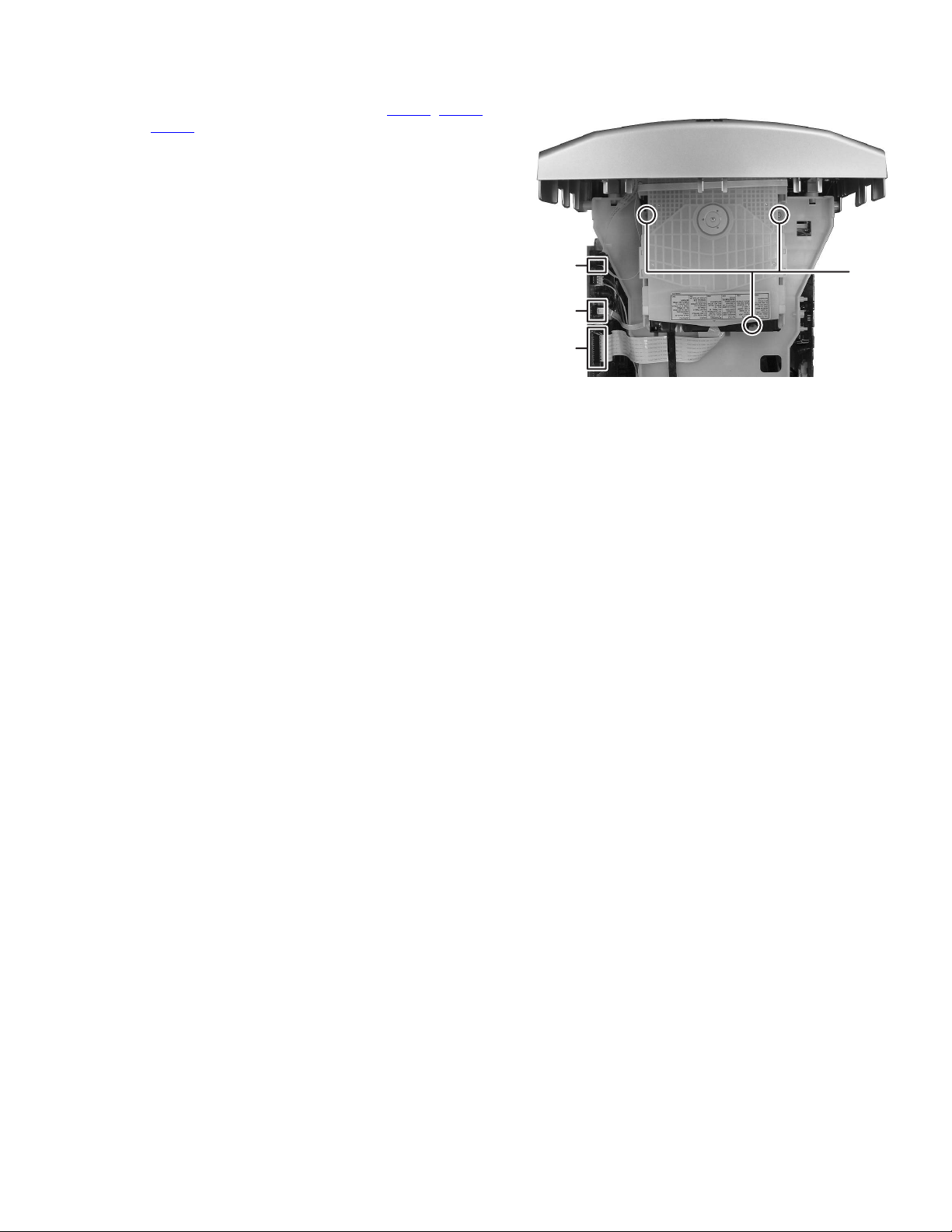
3.1 Main body
3.1.1 Removing the metal cover
(See Fig.1, 2)
(1) Remove the six screws A attaching the metal cover. (See
Fig.1)
(2) Remove the two screws B attaching the metal cover. (See
Fig.2)
L
A
A
K
J
A
A
A
Fig.1
B
Fig.2
1-8 (No.MB515)
Page 5
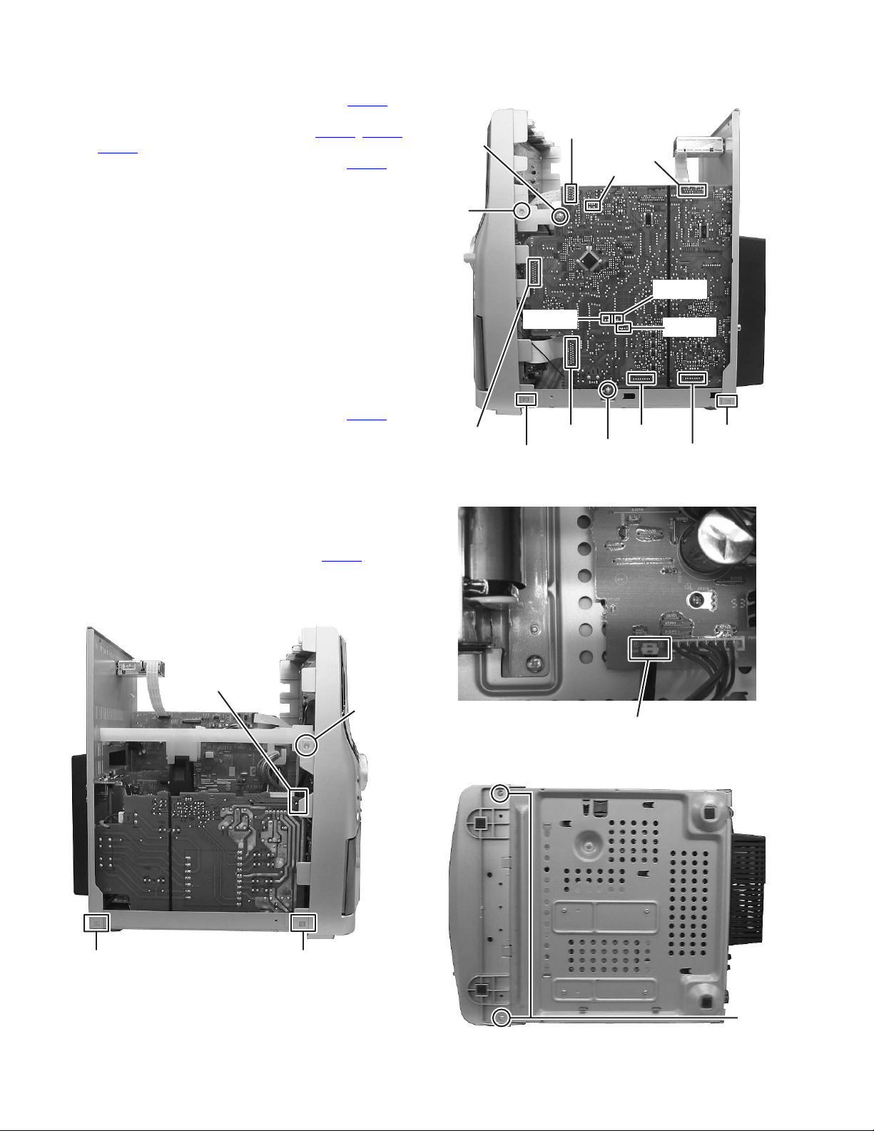
3.1.2 Removing the DVD mechanism assembly
(See Fig.3)
(1) Disconnect the card wires from connector CN300
and CN303 of the main board.
(2) Remove the three screws C attaching the DVD mecha-
nism assembly.
, CN301
CN300
CN302
CN301
C
Fig.3
(No.MB515)1-9
Page 6
3.1.3 Removing the front panel assembly
(See Fig.4 to 7)
(1) Disconnect the connector wires from connector CN103
the transformer board. (See Fig.4)
(2) Disconnect the card wires from connector CN303
and CN307 of the main board. (See Fig.5)
(3) Disconnect the connector wire from connector CN140
the amplifier board. (See Fig.6)
(4) Remove the two screws D attaching the front panel assem-
bly from bottom side of main body. (See Fig.7)
(5) Remove the one screw E attaching the front panel assem-
bly from left side of main body. (See Fig.4)
(6) Remove the one screw F attaching the front panel assem-
bly from right side of main body. (See Fig.5)
(7) Remove the one screw G attaching the earth wire from
switch board to main board. (See Fig.5)
(8) Disengage the hook a and hook b of the both side of the
front panel and then take out the front panel assembly.
(See Fig.4, 5)
3.1.4 Removing the center chassis
(See Fig.1, 5)
(1) Disconnect the connector wire from connector CN330
the main board. (See Fig. 5)
(2) Remove the one screw H attaching the center chassis.
(See Fig. 5)
(3) Remove the two screws J attaching the center chassis.
(See Fig. 1)
, CN306
of
of
of
H
F
CN307
CN306
CN313
b
CN303
CN330
G
Fig.5
CN335
CN309
CN312
CN314
d
CN311
3.1.5 Removing the tuner pack
(See Fig.1, 5)
(1) Disconnect the card wire from connector CN335
main board. (See Fig. 5)
(2) Remove the two screws K attaching the tuner pack. (See
Fig.1)
of the
CN103
E
CN140
Fig.6
c a
1-10 (No.MB515)
Fig.4
D
Fig.7
Page 7

3.1.6 Removing the rear panel
(See Fig.1, 4, 5, 8 and 9)
(1) Disconnect the parallel wire from connector CN210
sub woofer jack board. (See Fig.8)
(2) Remove the one screw L attaching the rear cover. (See
Fig. 1)
(3) Remove the twelve screws M attaching the rear panel.
(See Fig. 9)
(4) Disengage the hook c and hook d of the rear panel and
then take out the rear panel. (See Fig.4, 5)
of the
CN210
Fig.8
3.1.7 Removing the main board
(See Fig. 5)
(1) Disconnect the card wire from connector CN312
and CN314 of the main board.
(2) Disengage the connector CN309 and CN311 connect to
primary board and main board and then take out the main
board to upward.
, CN313
MMMM
Fig.9
(No.MB515)1-11
Page 8

3.1.8 Removing the primary board
(See Fig. 10)
(1) Disconnect the connector wire from connector CN119
the transformer board.
(2) Remove the one screw N attaching the primary board.
3.1.9 Removing the heat sink
(See Fig. 11)
(1) Remove the five screws P attaching the heat sink.
of
CN119
N
Fig.10
3.1.10 Removing the regulator board
(See Fig. 12)
(1) Disconnect the connector CN160
and regulator board.
P
Fig.11
connect to primary board
1-12 (No.MB515)
CN160
Fig.12
Page 9

3.1.11 Removing the cassette mechanism assembly
(See Fig.13)
(1) Remove the six screws Q attaching the cassette mecha-
nism assembly.
3.1.12 Removing the switch board
(See Fig.14)
(1) Take out the volume knob.
(2) Remove the twelve screws R attaching the switch board.
Q
Q
Fig.13
R
3.1.13 Removing the FL board
(See Fig.15)
(1) Remove the four screws S attaching the FL board.
(2) Remove the two screws T attaching the open/close switch
board.
R
Fig.14
SS
T
Fig.15
(No.MB515)1-13
Page 10

3.2 DVD mechanism
3.2.1 Removing the traverse mechanism
(See Fig.1 to 6)
(1) Remove the two screws A attaching the tramecha holder
from top side of DVD mechanism assembly. (See Fig.1)
(2) Remove the two screws B attaching the DVD module
board. (See Fig.2)
(3) Remove the four screws C attaching the CB holder and
take out it. (See Fig.3)
(4) Remove the four screws D attaching the traverse mecha-
nism. (See Fig.4)
(5) Solder the solder part of DVD pick up. (See Fig.5)
(6) Disconnect the card wire from CN101
DVD module board. (See Fig. 6)
Caution:
• Solder the short land section on the DVD pickup before dis-
connecting the card wire from the connector on the DVD
pickup. If the card wire is disconnected without attaching solders, the pickup may be destroyed by static electricity.
• When attaching the DVD pickup, be sure to remove solders
from the short land section after connecting the card wire to
the connector on the DVD pickup.
and CN201 on the
A
Clamper base
B
A
DVD mechanism assembly
Fig.1
DVD mechanism assembly
B
1-14 (No.MB515)
DVD module board
Fig.2
Page 11

DVD module board
Solder short land section
Fig.5
C
C
CC
Fig.3
DVD mechanism assembly
Traverse mechanism assembly
DVD module board
CN101
CN201
Fig.6
DD
Fig.4
(No.MB515)1-15
Page 12

3.2.2 Removing the pickup assembly
(See Fig.7 to 11)
(1) Remove the two rod springs pressing the guide shaft. (See
Fig.7)
(2) Remove the screw E and F attaching the spring holder.
(See Fig.8)
(3) Remove the read screw from traverse mechanism assem-
bly. (See Fig.9)
Caution:
When remove the lead screw, do not loss the middle
gear. (See Fig.10 and 11)
(4) Remove the bar spring pressing the shaft. (See Fig.10)
(5) Take out the pickup assembly from traverse mechanism
chassis by order. (See Fig.11)
(SHAFT)
(T.TABLE)
HOOK
(BAR SPRING)
Fig.10
ROD SPRING ROD SPRING
Fig.7
Spring holder
Fig.8
order 2
order 3
order 1
Fig.11
EF
Middle gear
1-16 (No.MB515)
Lead screw
Fig.9
Page 13

3.2.3 Removing the feed motor assembly
(See Fig.12)
(1) Remove the one screw G attaching the feed motor assem-
bly.
(2) Remove the feed motor wires from solder part of spindle
motor board.
Splder part
3.2.4 Removing the spindle motor assembly
(See Fig.13)
(1) Remove the two screws H attaching the spindle motor from
spindle motor board.
Middle gear
Lead screw
Fig.12
H
Spindle motor
Fig.13
G
(No.MB515)1-17
Page 14

3.2.5 Removing the tray assembly
(See Fig.14 & 15)
(1) Remove the two screws J attaching the clamper base.
(See Fig.14)
(2) Remove the one screw K attaching the shaft guide from
bottom side. (See Fig.14)
(3) Remove the two screws L attaching the shaft guide from
top side. (See Fig.15)
Caution:
When attach the tray assembly, boss of loading sub assembly
should attach to guide of bottom side at tray assembly. (See
Fig.15)
J
order 1
order 2
clamper base
L
K
Fig.15
[bottom side]
Fig.14
1-18 (No.MB515)
Page 15

SECTION 4
ADJUSTMENT
4.1 ATTENTION IN SERVICE OF DVD SECTION
(1) When pickup, Flash ROM ,DVD module board were changed, initialize EEPROM by all means.
(2) When full initialization was excuted, excute learning with a DVD test disc by all means.
Test disc : VT-501, VT-502
Learning method : It is adjusted automatically by normal playback of a DVD disc.
4.2 TEST MODE
In DVD test mode, initialization processing, the version of a microcomputer, a front end check, JITTA, and a laser current value
are indicated.
Step Operation Function Remarks
1 The AC code is pulled
out, The STOP and
PLAY key of a main unit
are pushed simultaneously.
The AC code is inserted
2 Version display
with the state of 1.
Push the PAUSE key of a
1
main unit.
NORMAL initialization
Push the STOP+POWER+
2
10 key of a remote control
for a long time.
FULL initialization
Push the STOP+POWER+
3
9 key of remote control.
It is made POWER ON in test
mode, and VERSION is displayed
on FL.
* segment of FL is RDS on at the
time of the completion of
initialization.
* segment of FL is COLT START
on at the time of the completion
of initialization.
Display the version of a micom
on FL.
FL display
12345678
TEST J C #
TJC#
TJC#
aa . cc
bbb
__ _
DVD
_
ee ee
.
dd 5sec
**
**
**
temporary
5sec
temporary
The version code is as the
following.
0x01: JC 0x02: 1U 0x03: D
0x04: E 0x05: 2U 0x06: 3U
0x07: UB 0x08: UT 0x09: 4U
0x0a: UY 0x0b: EE 0x0c: UF
Region code display
0x00: 0(Free) 0x01: 1 0x02: 2
0x04: 3 0x08: 4 0x10: 5 0x20: 6
0x40: 7 0x80: 8
"X" is indicated at the time as the
one except for the above.
The study state and an
initialization state from a back
end are displayed on the 10th
and 11th figure of FL display.
0xFF : Blank display
The study state(The 10th figure)
0x03: DVD Study un-completing,
CD Study un-completing. ("3")
0x02: DVD Study completing,
CD Study un-completing. ("2")
0x01: DVD Study un-completing,
CD Study completing. ("1")
0x00: DVD Study completing,
CD Study completing. ("0")
The initialization state
(The 11th figure)
0x03: FULL initialization end
("3")
0x00: NORMAL initialization end
("0")
0xFF: Initialization un-ending.
("Blank")
aa: Reserve(blank),
bbb: syscom version, ->017
cc: syscom model->_1/_3/51
dd:syscom destination
->U1/U2/U3/U4/EE
eeee: DVD backend version
->0271
syscon destination->U1:US/A
U2:UN U3:UG/UX
U4:UW/UY EE:EE
(No.MB515)1-19
Page 16

Step Operation Function Remarks
4 Push the MENU key of
remote control.
5 Push the MENU key of
remote control.
Push 1 key (of 10KEY) of
1
remote control.
Switch on the all-points light of
FL and LED.
Display the check mode of a
frontend on FL.
Starting of DISC & normal play
(Play from the started position)
FL display
12345678
HE KCC
HE KCC
Push 2 key (of 10KEY) of
2
remote control.
Push 3 key (of 10KEY) of
3
remote control.
Push 4 key (of 10KEY) of
4
remote control.
Push 5 key (of 10KEY) of
5
remote control.
Push 6 key (of 10KEY) of
6
remote control.
Push 7 key (of 10KEY) of
7
remote control.
Push 8 key (of 10KEY) of
8
remote control.
Push 9 key (of 10KEY) of
9
remote control.
Push 10 key (of 10KEY) of
10
remote control.
Push 0 key (of 10KEY) of
11
remote control.
Push +10 key (of 10KEY)
12
of remote control.
Push STOP key (of 10KEY)
13
of remote control.
Push OPEN/CLOSE key
14
(of 10KEY) of remote control.
Push PLAY key (of 10KEY)
15
of remote control.
Push the MENU key of
6
remote control.
Push the POWER key of
a main unit.
Existence of WOBBLE
0: WOBBLE_NO_CHECK
(Un-checking.)
1: WOBBLE_PRESS_MEDIA
(Press)
2: WOBBLE_MINUS_MEDIA
(DVD-R/-RW Media)
3: WOBBLE_PLUS_MEDIA
(DVD+R/+RW Media)
With no assignment
CD_LD lighting & laser current
display
DVD_LD lighting & laser current
display
DVD_SL x 1 JITTA measurement
mode
The contents of a backup memory
(0x00-0x46) display (BWD)
The contents of a backup memory
(0x00-0x46) display (FWD)
Temperature sensor value
(AD value) display
DVD-DL (Parallel , opposite),
DVD-SL
Search & JITTA measurement to
a predetermined position
MONITOR output change
1: SRV_MONI_CIRC
2: SRV_MONI_SERVO
3-5: SRV_MONI_ANALOG
6-7: SRV_MONI_DRC
8-11: SRV_MONI_SERVO_JIG
12: SRV_MONI_DEFAULT
Initialization of the contents of a
backup memory
Disk stop, LD-OFF
Tray open/close
Play disc
Return to STEP2.
Cancel test mode. It cancels, even if it does by all
HE KCC
CHECK
CHECK
*1 Fundamentally ,the mode carries out a toggle by pushing the MENU key.
********
********
********
********
********
********
********
********
********
********
********
Arg2-3: 0
Arg4-5: WOBBLE detection result
Arg2-3: Laser current value
(a BACKUP value, actual
measurement)
Arg4-5: 0
Arg2-3: Laser current value
(a BACKUP value, actual
measurement)
Arg4-5: 0
Arg2-3: Laser current value
(a BACKUP value, actual
measurement)
Arg4-5: actual measurement
Arg2-3: Backup memory address
(0x00-0x46)
Arg4-5: The contents of a backup
memory
Arg2-3: Backup memory address
(0x00-0x46)
Arg4-5: The contents of a backup
memory
Arg2-3: 0
Arg4-5: Temperature sensor value
Arg2-3: 0x00-0x06
(The measurement position in
VT501)
Arg4-5: JITTA value
Arg2-3: 0x00-0x0C
Arg4-5: 0
Arg2-3: Laser current value
(a BACKUP value, actual
measurement)
Arg4-5: JITTA value
STEP.
1-20 (No.MB515)
Page 17

SECTION 5
TROUBLESHOOTING
This service manual does not describe TROUBLESHOOTING.
(No.MB515)1-21
Page 18

Victor Company of Japan, Limited
Audio/Video Systems Category 10-1,1chome,Ohwatari-machi,Maebashi-city,371-8543,Japan
(No.MB515)
Printed in Japan
VPT
 Loading...