

Page 1
SERVICE MANUAL
NETWORK MEDIA SYSTEM
MB563200611
DD-8B,DD-8E,DD-8EN,DD-8EV,
DD-8EE,DD-3B,DD-3E,DD-3EN,
DD-3EV,DD-3EE
SP-DD8S
SP-DD8F SP-DD8F
Lead free solder used in the board (material : Sn-Ag-Cu, melting point : 219 Centigrade)
1 PRECAUTION. . . . . . . . . . . . . . . . . . . . . . . . . . . . . . . . . . . . . . . . . . . . . . . . . . . . . . . . . . . . . . . . . . . . . . . . . 1-4
2 SPECIFIC SERVICE INSTRUCTIONS . . . . . . . . . . . . . . . . . . . . . . . . . . . . . . . . . . . . . . . . . . . . . . . . . . . . . . 1-8
3 DISASSEMBLY . . . . . . . . . . . . . . . . . . . . . . . . . . . . . . . . . . . . . . . . . . . . . . . . . . . . . . . . . . . . . . . . . . . . . . . 1-9
4 ADJUSTMENT . . . . . . . . . . . . . . . . . . . . . . . . . . . . . . . . . . . . . . . . . . . . . . . . . . . . . . . . . . . . . . . . . . . . . . . 1-32
5 TROUBLESHOOTING . . . . . . . . . . . . . . . . . . . . . . . . . . . . . . . . . . . . . . . . . . . . . . . . . . . . . . . . . . . . . . . . . 1-35
CA-DD8
(Only for DD-8 and DD-3)
COPYRIGHT © 2006 Victor Company of Japan, Limited
SP-PWDD8
TABLE OF CONTENTS
SP-DD8S
CA-DD3SP-DD3F SP-DD3F SP-PWDD3
No.MB563
2006/11
Page 2
SPECIFICATION
Main unit (CA-DD8/CA-DD3)
Tuner FM frequency : 87.50 MHz - 108.00 MHz
AM frequency : 522 kHz - 1 629 kHz
Terminal (front of the main unit) Audio output headphone terminal × 1
Impedance : 16 Ω to 1 kΩ
USB digital input terminal × 1
Analog input terminal × 1
Stereo mini jack
Analog output terminal × 1
Stereo mini jack
Terminal (rear of the main unit) Optical digital input terminal × 1
-23 dBm to -15 dBm
Optical digital output terminal × 1
-23 dBm to -15 dBm
System terminal × 1
Component video output terminals (3) × 1
Y : 1.0 Vp-p, sync negative, 75 Ω terminated
PB : 0.7 Vp-p, 75 Ω terminated
PR : 0.7 Vp-p, 75 Ω terminated
Audio input terminals (2) × 1
500 mV/47 kΩ
SCART terminal × 1
AM antenna terminal × 1
FM antenna terminal × 1
Ethernet terminal
HDMI monitor output terminal
USB Compatible with USB 2.0 Full-Speed
Compatible device : Mass storage class device
Compatible file system : FAT16, FAT32
Bus power supply : Max. 500 mA
General Power source : AC 230 V , 50 Hz
Power consumption (in operation) : 25 W
Power consumption (on standby) : 0.5 W
Dimensions (W × H × D) : 445 mm × 55 mm × 286.4 mm (including projecting parts)
Weight : 3.5 kg (CA-DD8), 3.0 kg (CA-DD3)
Subwoofer for DD-8 (SP-PWDD8)
Type Bass reflex type, Magnetically shielded type
Amplifier Subwoofer : 120 W at 4 Ω (110 Hz, THD 10%)
Left/right speaker : 25 W × 2 at 3 Ω (1 kHz, THD 10%)
Center surround speaker : 25 W × 2 at 3 Ω (1 kHz, THD 10%)
Speaker 16 cm cone
Power handling capacity : 120 W
Impedance : 4 Ω
Frequency range : 30 Hz - 230 Hz
Sound pressure level : 72 dB/W·m
General Power source : AC 230 V , 50 Hz
Power consumption : 120 W
Dimensions (W × H × D) : 242 mm × 364 mm × 363 mm
Weight : 12.6 kg
1-2 (No.MB563)
Page 3
Subwoofer for DD-3 (SP-PWDD3)
Type Bass reflex type
Amplifier Subwoofer : 120 W at 4 Ω (110 Hz, THD 10%)
Left/right speaker : 25 W × 2 at 3 Ω (1 kHz, THD 10%)
Center surround speaker : 25 W × 2 at 3 Ω (1 kHz, THD 10%)
Speaker 16 cm cone
Power handling capacity : 120 W
Impedance : 4 Ω
Frequency range : 30 Hz - 230 Hz
Sound pressure level : 72 dB/W·m
General Power source : AC 230 V , 50 Hz
Power consumption : 120 W
Dimensions (W × H × D) : 242 mm × 364 mm × 363 mm
Weight : 12.3 kg
Left and right speakers forDD-8 (SP-DD8F)
Type 2-way 3-speaker bass reflex type, Magnetically shielded type
Speaker 8 cm cone × 2 + 2 cm dome
Power handling capacity 30 W
Impedance 3 Ω
Frequency range 60 Hz - 40 kHz
Sound pressure level 81 dB/W·m
Dimensions (W × H × D) 289 mm × 1 101 mm × 289 mm
Weight (1 unit) 10.0 kg
Left and right speakers forDD-3 (SP-DD3F)
Type 2-way acoustic suspension type, Magnetically shielded type
Speaker 9.5 cm × 1 cm direct drive + 2 cm dome
Power handling capacity 30 W
Impedance 3 Ω
Frequency range 100 Hz - 40 kHz
Sound pressure level 78 dB/W·m
Dimensions (W × H × D) 165 mm × 376 mm × 165 mm (including stand)
Weight (1 unit) 1.0 kg (including stand)
Center surround speaker for DD-8/DD-3 (SP-DD8S)
Type 1-way acoustic suspension type, Magnetically shielded type
Speaker 9.5 cm × 1 cm direct-drive
Power handling capacity 30 W
Impedance 3 Ω
Frequency range 120 Hz - 40 kHz
Sound pressure level 79 dB/W·m
Dimensions (W × H × D) 344 mm × 61 mm × 76 mm (including stand)
Weight 0.95 kg (including stand)
Designs and specifications are subject to change without notice.
(No.MB563)1-3
Page 4
SECTION 1
PRECAUTION
1.1 Safety Precautions
(1) This design of this product contains special hardware and
many circuits and components specially for safety purposes. For continued protection, no changes should be made
to the original design unless authorized in writing by the
manufacturer. Replacement parts must be identical to
those used in the original circuits. Services should be performed by qualified personnel only.
(2) Alterations of the design or circuitry of the product should
not be made. Any design alterations of the product should
not be made. Any design alterations or additions will void
the manufacturers warranty and will further relieve the
manufacture of responsibility for personal injury or property
damage resulting therefrom.
(3) Many electrical and mechanical parts in the products have
special safety-related characteristics. These characteristics are often not evident from visual inspection nor can the
protection afforded by them necessarily be obtained by using replacement components rated for higher voltage, wattage, etc. Replacement parts which have these special
safety characteristics are identified in the Parts List of Service Manual. Electrical components having such features
are identified by shading on the schematics and by ( ) on
the Parts List in the Service Manual. The use of a substitute
replacement which does not have the same safety characteristics as the recommended replacement parts shown in
the Parts List of Service Manual may create shock, fire, or
other hazards.
(4) The leads in the products are routed and dressed with ties,
clamps, tubings, barriers and the like to be separated from
live parts, high temperature parts, moving parts and/or
sharp edges for the prevention of electric shock and fire
hazard. When service is required, the original lead routing
and dress should be observed, and it should be confirmed
that they have been returned to normal, after reassembling.
(5) Leakage shock hazard testing
After reassembling the product, always perform an isolation check on the exposed metal parts of the product (antenna terminals, knobs, metal cabinet, screw heads,
headphone jack, control shafts, etc.) to be sure the product
is safe to operate without danger of electrical shock.Do not
use a line isolation transformer during this check.
• Plug the AC line cord directly into the AC outlet. Using a
"Leakage Current Tester", measure the leakage current
from each exposed metal parts of the cabinet, particularly any exposed metal part having a return path to the
chassis, to a known good earth ground. Any leakage current must not exceed 0.5mA AC (r.m.s.).
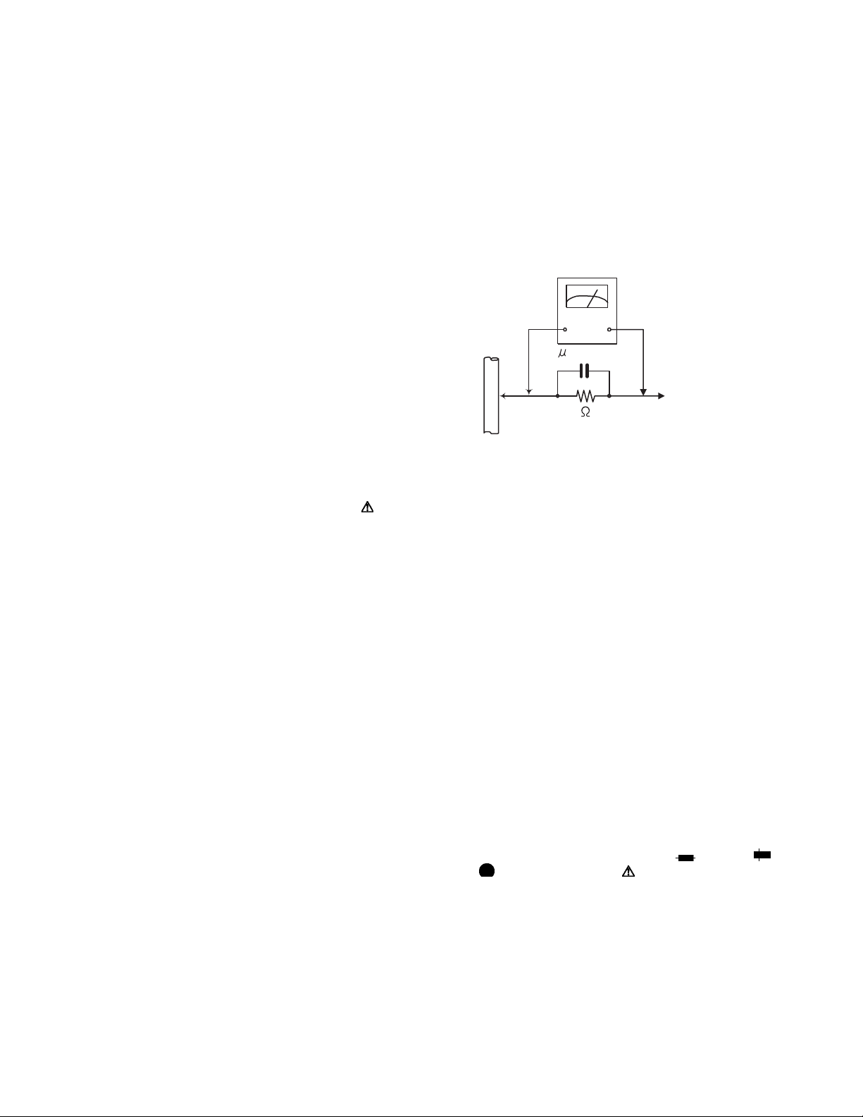
• Alternate check method
Plug the AC line cord directly into the AC outlet. Use an
AC voltmeter having, 1,000Ω per volt or more sensitivity
in the following manner. Connect a 1,500Ω 10W resistor
paralleled by a 0.15µF AC-type capacitor between an ex-
posed metal part and a known good earth ground.
Measure the AC voltage across the resistor with the AC
voltmeter.
Move the resistor connection to each exposed metal
part, particularly any exposed metal part having a return
path to the chassis, and measure the AC voltage across
the resistor. Now, reverse the plug in the AC outlet and
repeat each measurement. Voltage measured any must
not exceed 0.75 V AC (r.m.s.). This corresponds to 0.5
mA AC (r.m.s.).
AC VOLTMETER
(Having 1000
ohms/volts,
or more sensitivity)
0.15 F AC TYPE
Place this
probe on
1500 10W
Good earth ground
1.2 Warning
(1) This equipment has been designed and manufactured to
meet international safety standards.
(2) It is the legal responsibility of the repairer to ensure that
these safety standards are maintained.
(3) Repairs must be made in accordance with the relevant
safety standards.
(4) It is essential that safety critical components are replaced
by approved parts.
(5) If mains voltage selector is provided, check setting for local
voltage.
1.3 Caution
Burrs formed during molding may be left over on some parts
of the chassis.
Therefore, pay attention to such burrs in the case of preforming repair of this system.
1.4 Critical parts for safety
In regard with component parts appearing on the silk-screen
printed side (parts side) of the PWB diagrams, the parts that are
printed over with black such as the resistor ( ), diode ( )
and ICP ( ) or identified by the " " mark nearby are critical
for safety. When replacing them, be sure to use the parts of the
same type and rating as specified by the manufacturer.
(This regulation dose not Except the J and C version)
each exposed
metal part.
1-4 (No.MB563)
Page 5

1.5 Safety Precautions (U.K only)
(1) This design of this product contains special hardware and many circuits and components specially for safety purposes. For con-
tinued protection, no changes should be made to the original design unless authorized in writing by the manufacturer. Replacement parts must be identical to those used in the original circuits.
(2) Any unauthorised design alterations or additions will void the manufacturer's guarantee; furthermore the manufacturer cannot
accept responsibility for personal injury or property damage resulting therefrom.
(3) Essential safety critical components are identified by ( ) on the Parts List and by shading on the schematics, and must never
be replaced by parts other than those listed in the manual. Please note however that many electrical and mechanical parts in
the product have special safety related characteristics. These characteristics are often not evident from visual inspection. Parts
other than specified by the manufacturer may not have the same safety characteristics as the recommended replacement parts
shown in the Parts List of the Service Manual and may create shock, fire, or other hazards.
(4) The leads in the products are routed and dressed with ties, clamps, tubings, barriers and the like to be separated from live parts,
high temperature parts, moving parts and/or sharp edges for the prevention of electric shock and fire hazard. When service is
required, the original lead routing and dress should be observed, and it should be confirmed that they have been returned to
normal, after re-assembling.
1.5.1 Warning
(1) Service should be performed by qualified personnel only.
(2) This equipment has been designed and manufactured to meet international safety standards.
(3) It is the legal responsibility of the repairer to ensure that these safety standards are maintained.
(4) Repairs must be made in accordance with the relevant safety standards.
(5) It is essential that safety critical components are replaced by approved parts.
(6) If mains voltage selector is provided, check setting for local voltage.
Burrs formed during molding may be left over on some parts of the chassis. Therefore,
pay attention to such burrs in the case of preforming repair of this system.
(No.MB563)1-5
Page 6
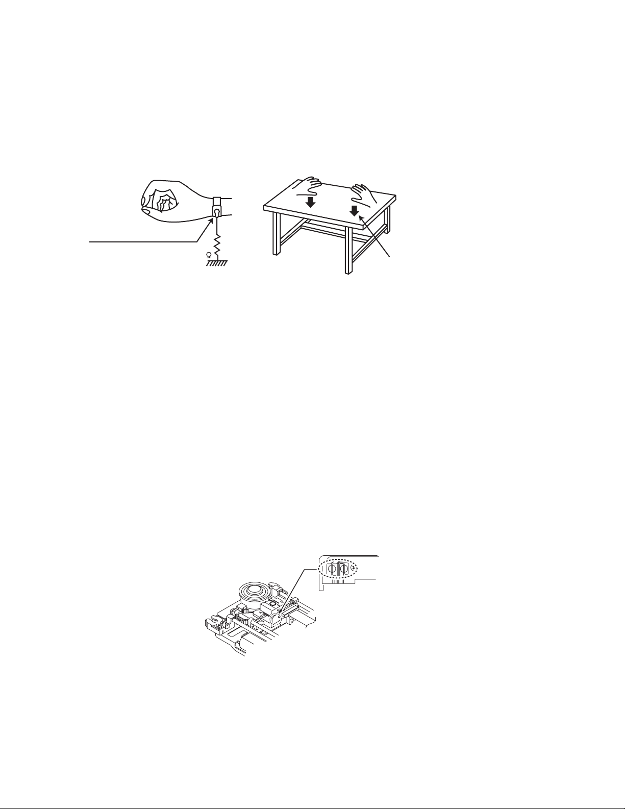
1.6 Preventing static electricity
Electrostatic discharge (ESD), which occurs when static electricity stored in the body, fabric, etc. is discharged, can destroy the laser
diode in the traverse unit (optical pickup). Take care to prevent this when performing repairs.
1.6.1 Grounding to prevent damage by static electricity
Static electricity in the work area can destroy the optical pickup (laser diode) in devices such as laser products.
Be careful to use proper grounding in the area where repairs are being performed.
(1) Ground the workbench
Ground the workbench by laying conductive material (such as a conductive sheet) or an iron plate over it before placing the
traverse unit (optical pickup) on it.
(2) Ground yourself
Use an anti-static wrist strap to release any static electricity built up in your body.
(caption)
Anti-static wrist strap
1M
Conductive material
(conductive sheet) or iron palate
(3) Handling the optical pickup
• In order to maintain quality during transport and before installation, both sides of the laser diode on the replacement optical
pickup are shorted. After replacement, return the shorted parts to their original condition.
(Refer to the text.)
• Do not use a tester to check the condition of the laser diode in the optical pickup. The tester's internal power source can easily
destroy the laser diode.
1.7 Handling the traverse unit (optical pickup)
(1) Do not subject the traverse unit (optical pickup) to strong shocks, as it is a sensitive, complex unit.
(2) Cut off the shorted part of the flexible cable using nippers, etc. after replacing the optical pickup. For specific details, refer to the
replacement procedure in the text. Remove the anti-static pin when replacing the traverse unit. Be careful not to take too long a
time when attaching it to the connector.
(3) Handle the flexible cable carefully as it may break when subjected to strong force.
(4) I t is not possible to adjust the semi-fixed resistor that adjusts the laser power. Do not turn it.
1.8 Attention when traverse unit is decomposed
*Please refer to "Disassembly method" in the text for the pickup unit.
• Apply solder to the short land sections before the card wire is disconnected from the connecto on the servo board. (If the card wire
is disconnected without applying solder, the pickup may be destroyed by static electricity.)
• In the assembly, be sure to remove solder from the short land sections after connecting the card wire.
Solder short land section
1-6 (No.MB563)
Page 7
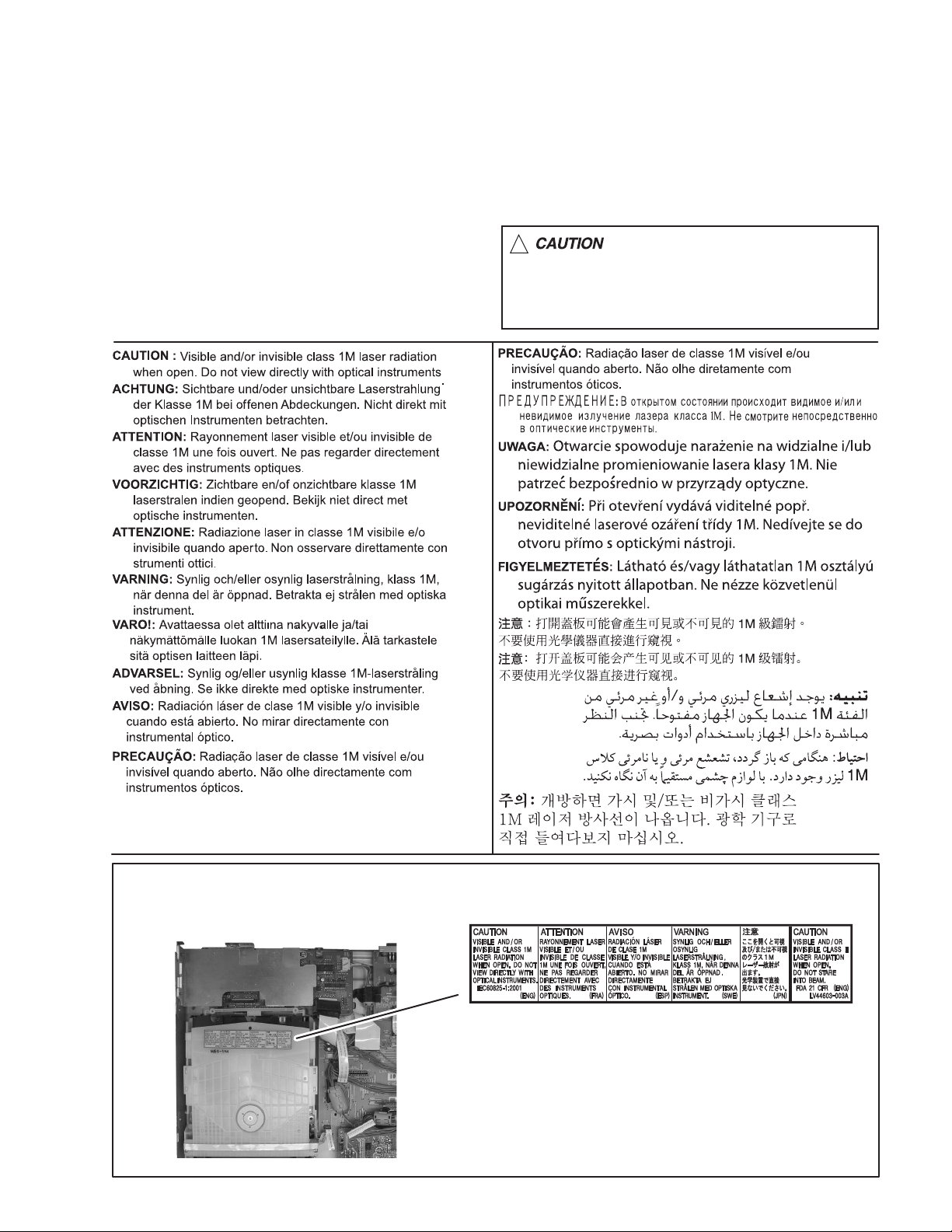
1.9 Important for laser products
1.CLASS 1 LASER PRODUCT
2.CAUTION :
Visible and/or invisible class 1M laser radiation
when open. Do not view directly with optical instruments.
3.CAUTION : Visible and/or invisible laser radiation when
open and inter lock failed or defeated. Avoid direct
exposure to beam.
4.CAUTION : This laser product uses visible and/or invisible
laser radiation and is equipped with safety switches which
prevent emission of radiation when the drawer is open and
the safety interlocks have failed or are defeated. It is
dangerous to defeat the safety switches.
5.CAUTION : If safety switches malfunction, the laser is able
to function.
6.CAUTION : Use of controls, adjustments or performance of
procedures other than those specified here in may result in
hazardous radiation exposure.
!
Please use enough caution not to
see the beam directly or touch it
in case of an adjustment or operation
check.
REPRODUCTION AND POSITION OF LABELS and PRINT
WARNING LABEL and PRINT
(No.MB563)1-7
Page 8

SECTION 2
SPECIFIC SERVICE INSTRUCTIONS
This service manual does not describe SPECIFIC SERVICE INSTRUCTIONS.
1-8 (No.MB563)
Page 9
SECTION 3
DISASSEMBLY
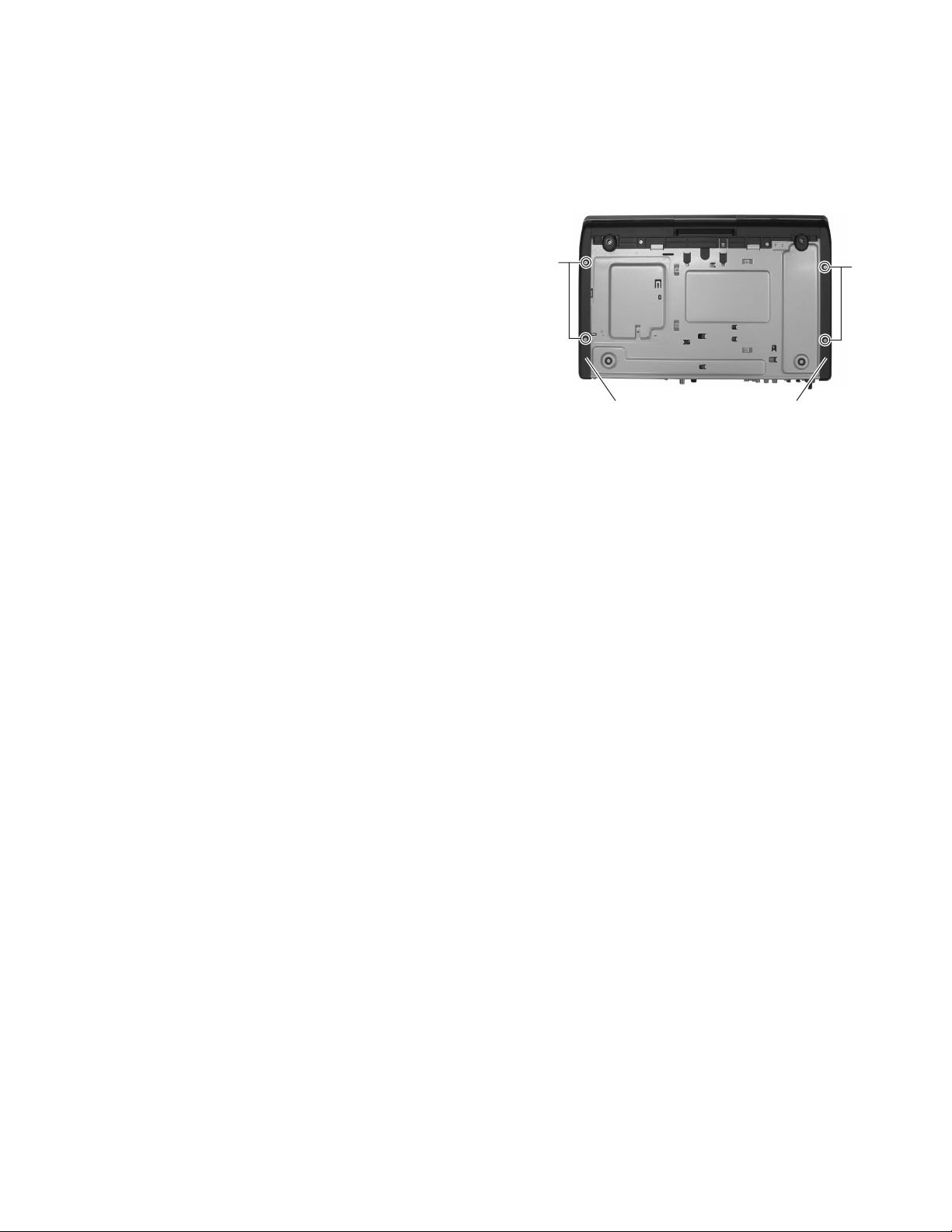
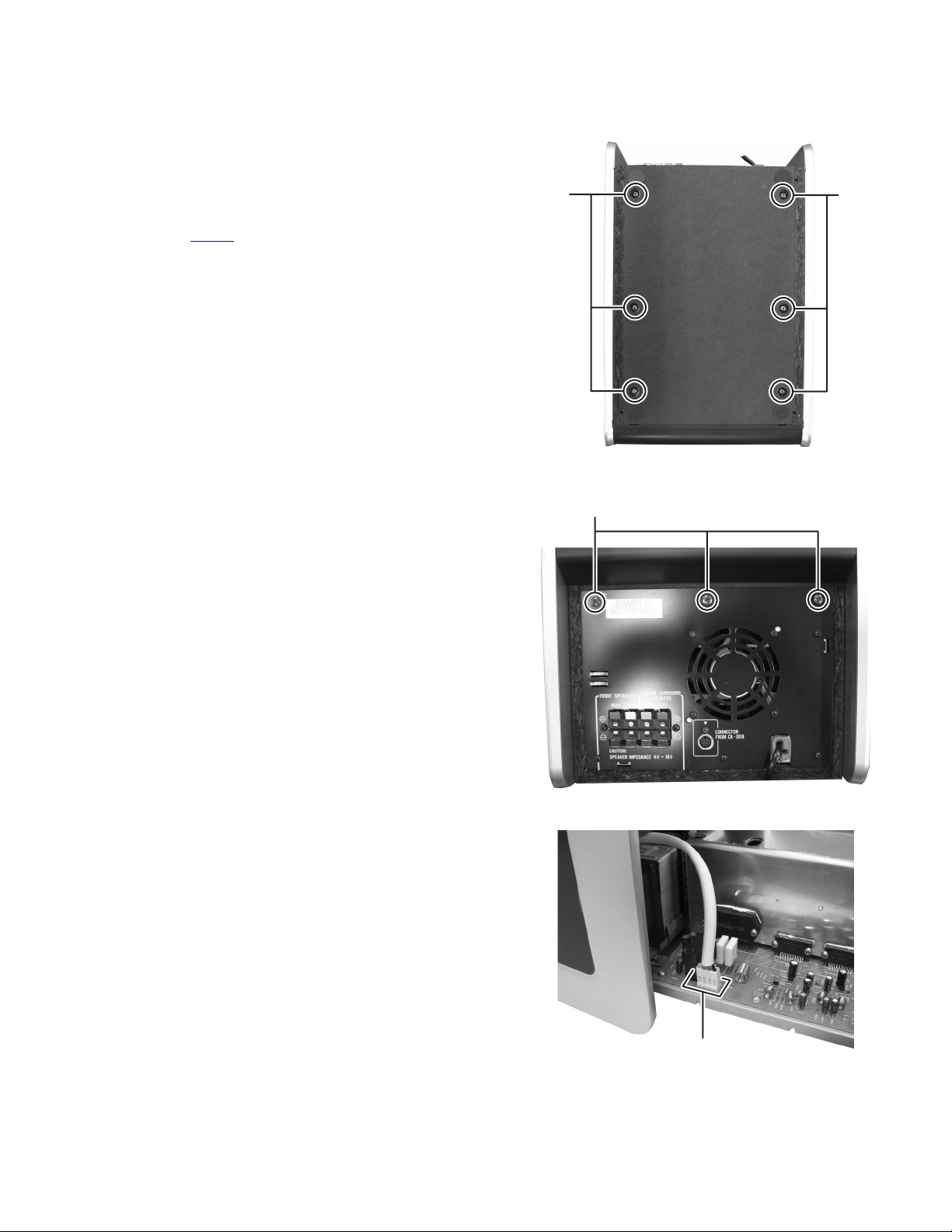
3.1 Main body section
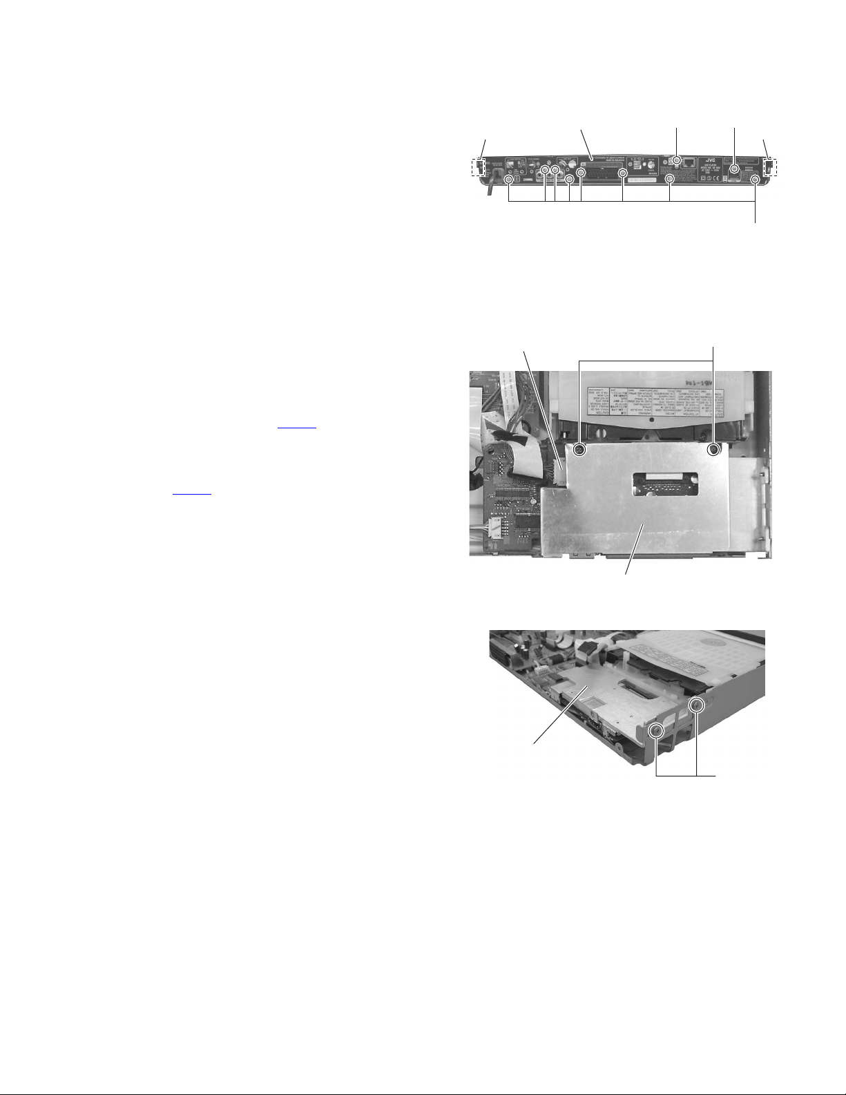
3.1.1 Removing the side panel L, R
(See Fig.1)
(1) From the bottom sides of the main body, remove the four
screws A attaching the side panel L and side panel R.
(2) Remove the side panel L and side panel R.
A
A
Side panel RSide panel L
Fig.1
(No.MB563)1-9
Page 10

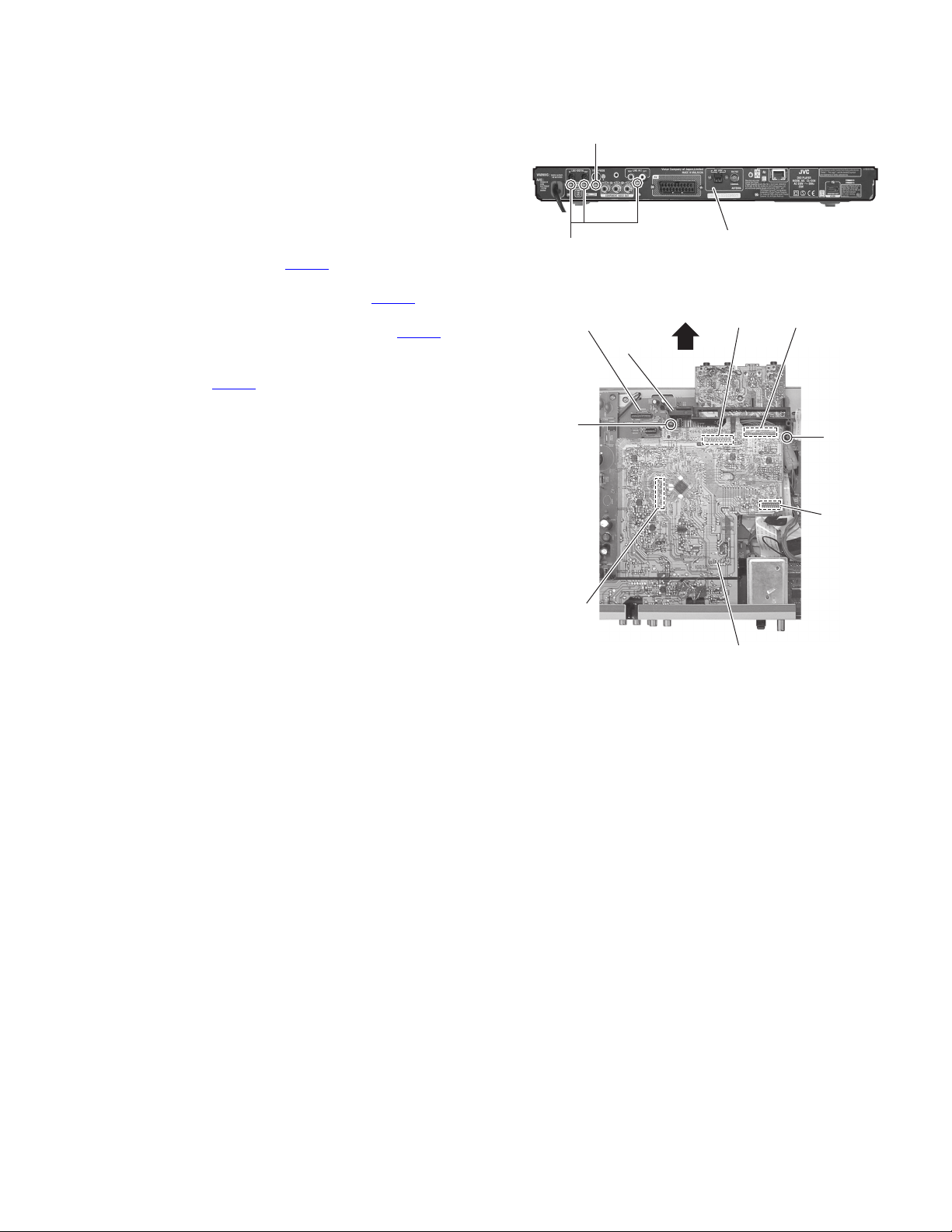
3.1.2 Removing the top cover
(See Figs. 2 to 9)
• Remove the side panel L and side panel R.
(1) From the left and right side of the main body, remove the
two screws B and two screws B' (See Figs.2 and 3)
Reference:
When attaching the screws B', attach the earth wires
with them. (See Figs. 2 and 3)
(2) From the back side of the main body, remove the two
screws C attaching the rear panel. (See Fig.4)
(3) Insert the minus driver a space a of the door arm to the
front base. (See Fig.5)
(4) Moving the minus driver in the direction of the arrow. (See
Fig.5)
(5) Take out the door from the front base in the direction of the
arrow. (See Fig.6)
(6) Remove the two screws D attaching the top cover. (See
Fig.7)
(7) From the top side of the main body, open the top panel in
the direction of the arrow. (See Fig.8)
(8) From front side of the main body, disconnect the card wire
from the connector CN451
(9) Remove the top cover.
on the main board. (See Fig.9)
Top cover
Top cover
B' B
Fig.2
B'
Fig.3
C
Top cover
B
Rear panel
Fig.4
Front base Door arm
Fig.5
a
1-10 (No.MB563)
Page 11
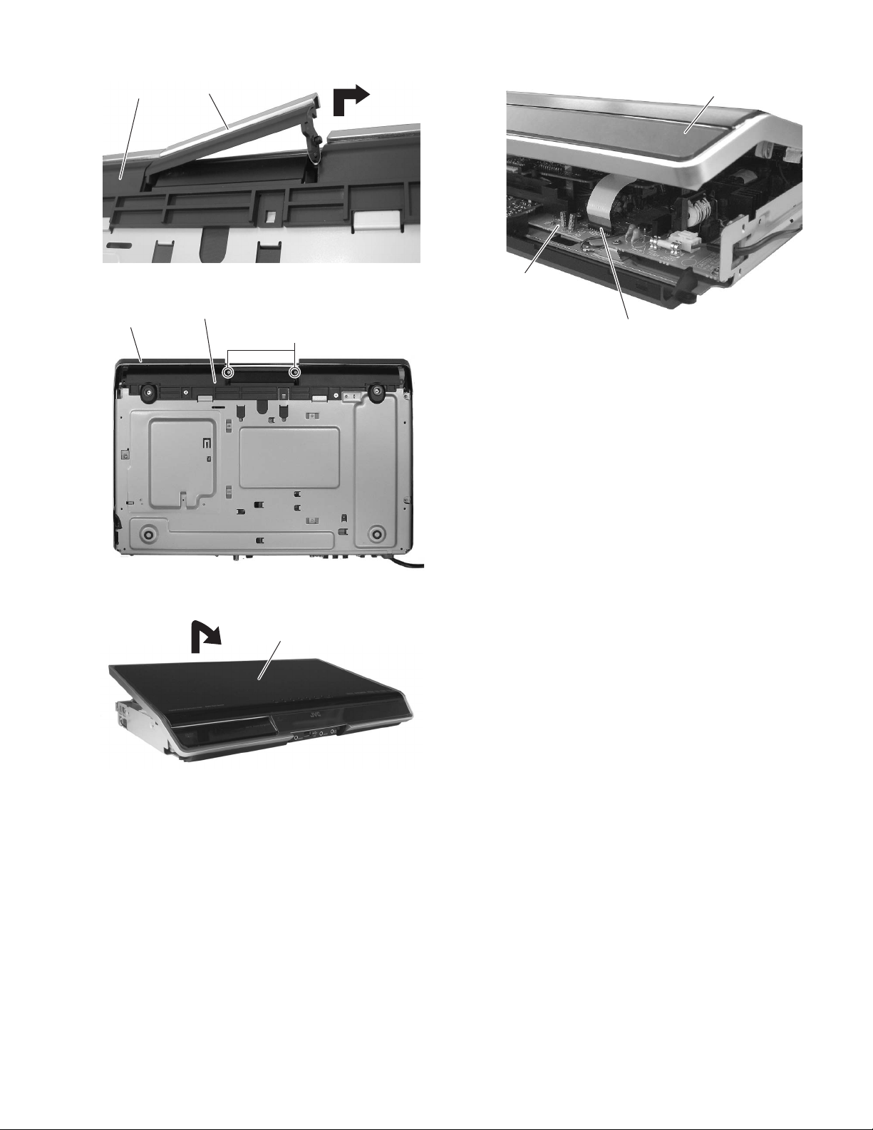
Front base
Door
Top cover
Top cover
Front base
Fig.6
Fig.7
Top cover
D
Main board
CN451
Fig.9
Fig.8
(No.MB563)1-11
Page 12

3.1.3 Removing the front base
(See Fig.10)
• Remove the side panel L, side panel R and top cover.
(1) From the bottom side of the main body, remove the four
screws E attaching the front base.
(2) Release the joint b of the front base and then remove in the
direction of the arrow.
E
Front base
b
Fig.10
E
1-12 (No.MB563)
Page 13
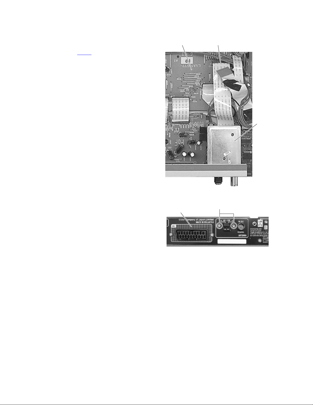
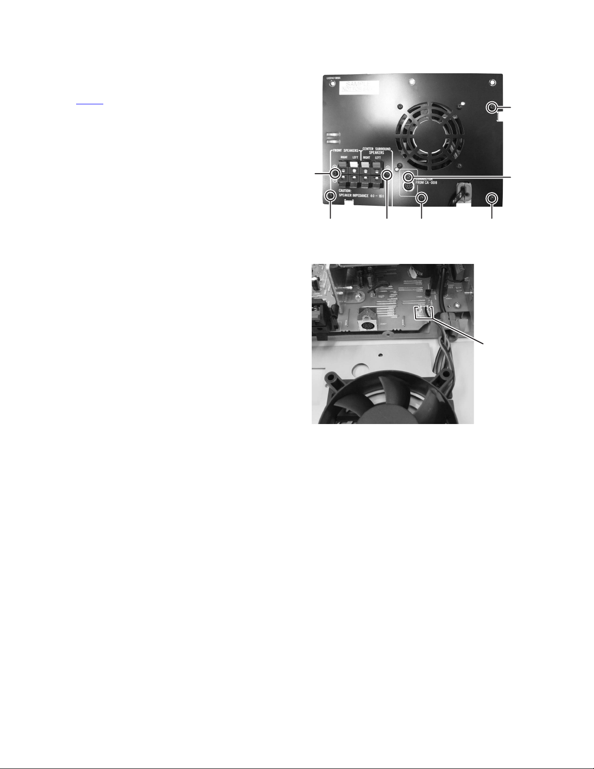
3.1.4 Removing the audio board
(See Figs.11 and 12)
• Remove the side panel L, side panel R, top cover and front
base.
(1) From the back side of the main body, remove the screw F
and three screws G attaching the audio board to the rear
panel. (See Fig.11)
(2) From top side of the main body, remove the two screws H
attaching the holder. (See Fig.12)
(3) Take out the holder from the main body in the direction of
the arrow. (See Fig.12)
(4) Disconnect the connector CN202
the main board. (See Fig.12)
(5) Disconnect the wire from the connector CN204
dio board. (See Fig.12)
(6) Disconnect the card wire from the connector CN201
audio board. (See Fig.12)
(7) Remove the audio board and then disconnect the wire from
the connector CN421
(8) Take out the audio board from the main body.
on the main board. (See Fig.12)
on the audio board from
on the au-
on the
F
G
Main board
Holder
Rear panel
Fig.11
CN202 CN204
H
CN421
H
CN201
Audio board
Fig.12
(No.MB563)1-13
Page 14
3.1.5 Removing the tuner
r
(See Figs.13 and 14)
• Remove the side panel L, side panel R, top cover, front base
and audio board.
(1) From the top side of the main body, disconnect the card
wire from the connector CN441
Fig.13)
(2) From the back side of the main body, remove the two
screws J attaching the tuner to the rear panel and then take
out the tuner. (See Fig.14)
on the main board. (See
CN441Main board
Tune
Rear panel
Fig.13
J
Fig.14
1-14 (No.MB563)
Page 15
3.1.6 Removing the rear panel
(See Fig.15)
• Remove the side panel L, side panel R, top cover, front base,
audio board and tuner.
(1) From the back side of the main body, remove the eight
screws K, screw M and N attaching the rear panel.
(2) Release the two joints c of the rear panel.
(3) Take out the rear panel from the main body.
3.1.7 Removing the LAN board assembly
(See Figs.16 and 17)
• Remove the side panel L, side panel R, top cover, front base,
audio board, tuner and rear panel.
(1) From the top side of the main body, remove the two screws
P attaching the LAN board assembly. (See Fig.16)
(2) Disconnect the wire from the connector on the LAN board
assembly. (See Fig.16)
(3) Lift up the LAN board assembly and then disconnect the
card wire from the connector CN351
(See Fig.17)
(4) Take out the LAN board assembly from the main body.
CAUTION:
The connector CN351
of connector.
is easy to broken when release the lock
on the DVD board.
Rear panel
MN
cc
K
Fig.15
Connecter
P
DVD assembry
LAN board assembly
Fig.16
Q
Fig.17
(No.MB563)1-15
Page 16
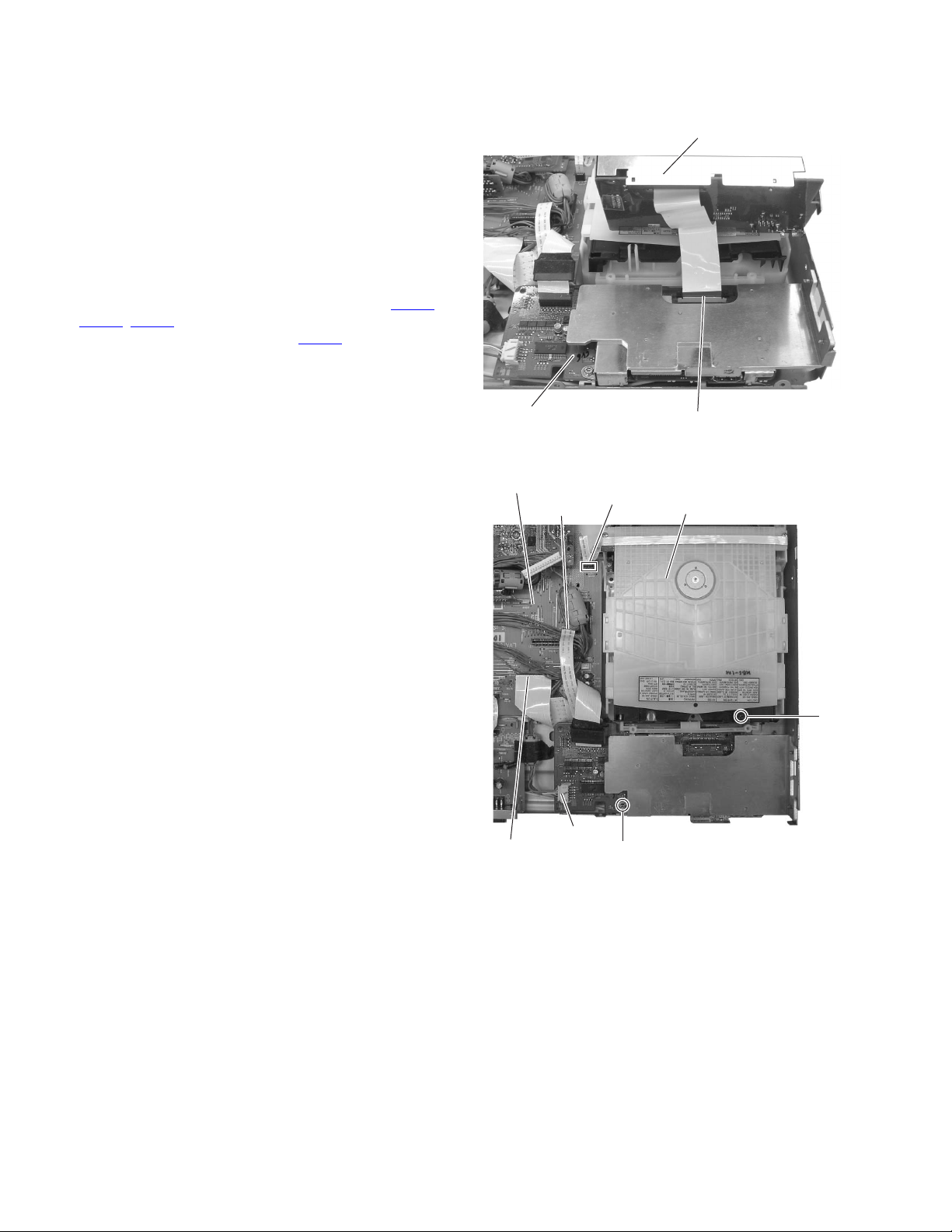
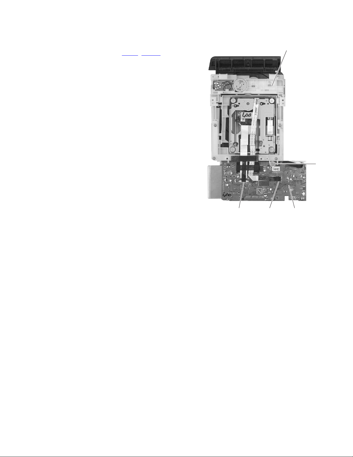
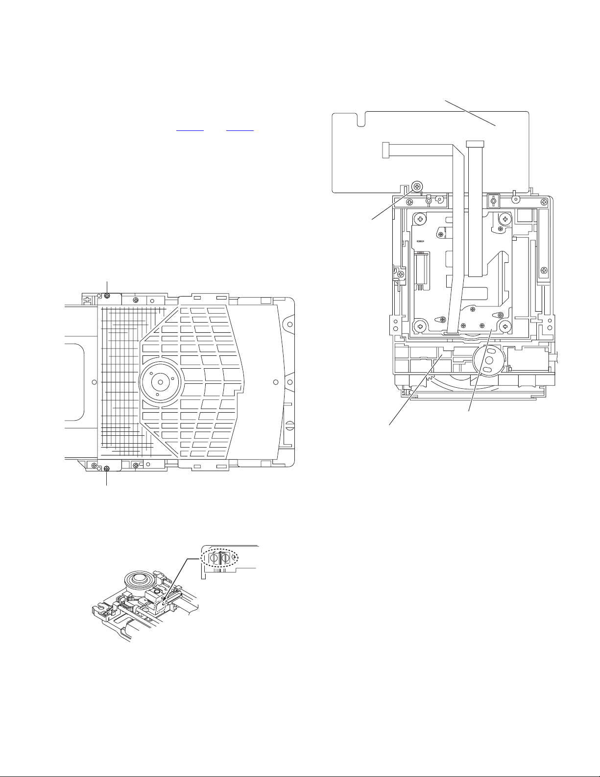
3.1.8 Removing the DVD assembly
(See Figs.18 and 19)
• Remove the side panel L, side panel R, top cover, front base,
audio board, tuner, rear panel and LAN board assembly.
(1) From the right side of the main body, remove the two
screws Q attaching the DVD assembly. (See Fig.18)
(2) From the top side of the main body, remove the screw R
and screw S attaching the DVD assembly. (See Fig.19)
Reference:
When removing the screw R, use a screwdriver shown
as follows.
TORX Driver: size T10
Parts number: DR-L70
(3) Disconnect the card wires from connectors (CN471
CN472, CN473) on the main board. (See Fig.19)
(4) Disconnect the wire from connector CN704
sembly. (See Fig.19)
(5) Take out the DVD assembly from the main body.
on the DVD as-
LAN board assembly
,
DVD board
Main board
CN473
CN472
CN704
CN471
R
CN351
Fig.18
DVD assembly
S
1-16 (No.MB563)
Fig.19
Page 17
3.1.9 Removing the DVD board
(See Fig.20)
• Remove the DVD assembly.
(1) From the bottom side of the DVD assembly, disconnect the
card wires from the connectors (CN101
DVD board.
(2) Remove the screw T attaching the DVD board to the DVD
assembly. (See Fig.20)
(3) Take out the DVD board.
, CN1201) on the
DVD assembly
T
CN101 CN201 DVD board
Fig.20
(No.MB563)1-17
Page 18
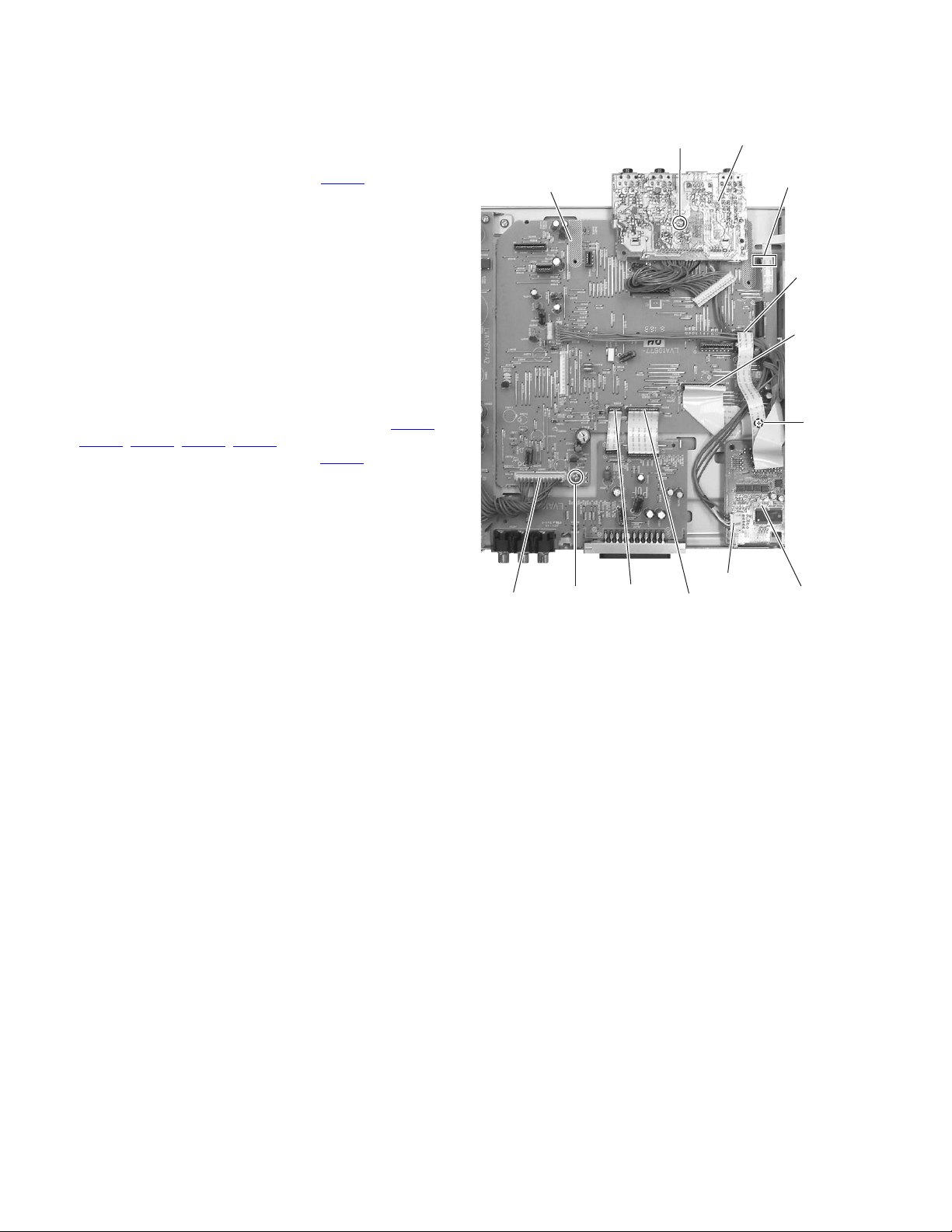
3.1.10 Removing the jack board
(See Fig.21)
• Remove the side panel L, side panel R, top cover, front base,
audio board and LAN board assembly.
(1) From the top side of the main body, remove the screw U at-
taching the jack board.
(2) Disconnect the wire from the connector CN704
board.
(3) Take out the jack board from the main body.
3.1.11 Removing the main board
(See Fig.21)
• Remove the side panel L, side panel R, top cover, front base,
audio board, tuner, rear panel, LAN board assembly and jack
board.
(1) From the top side of the main body, remove the screw V
and screw V' attaching the main board.
Reference:
When attaching the screw V', attach the earth wire with
it. (See Fig. 21)
(2) Disconnect the card wires from the connectors (CN461
CN463, CN471, CN472, CN473) on the main board.
(3) Disconnect the wire from the connector CN901
board.
(4) Take out the main board from the main body.
on the DVD
on the main
U
Main board
,
Jack board
CN471
CN473
CN472
V'
CN901
V
CN461
CN463
Fig.21
CN704
DVD board
1-18 (No.MB563)
Page 19
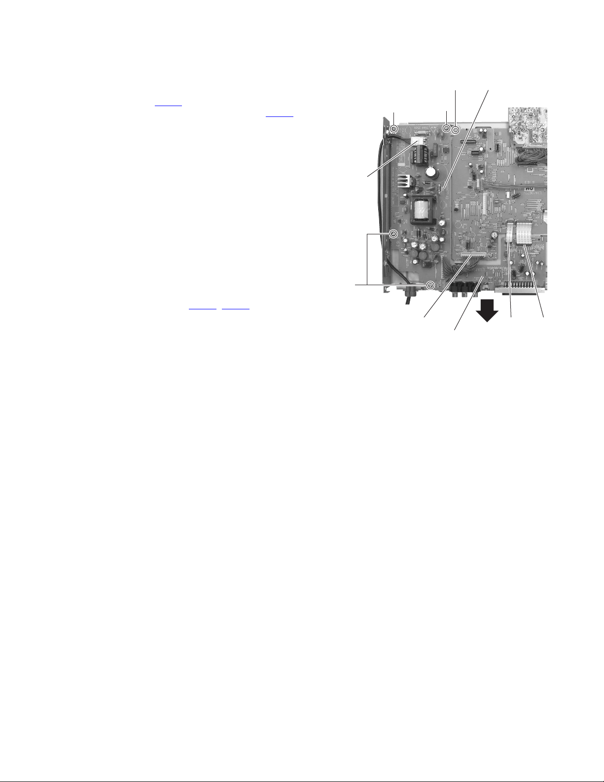
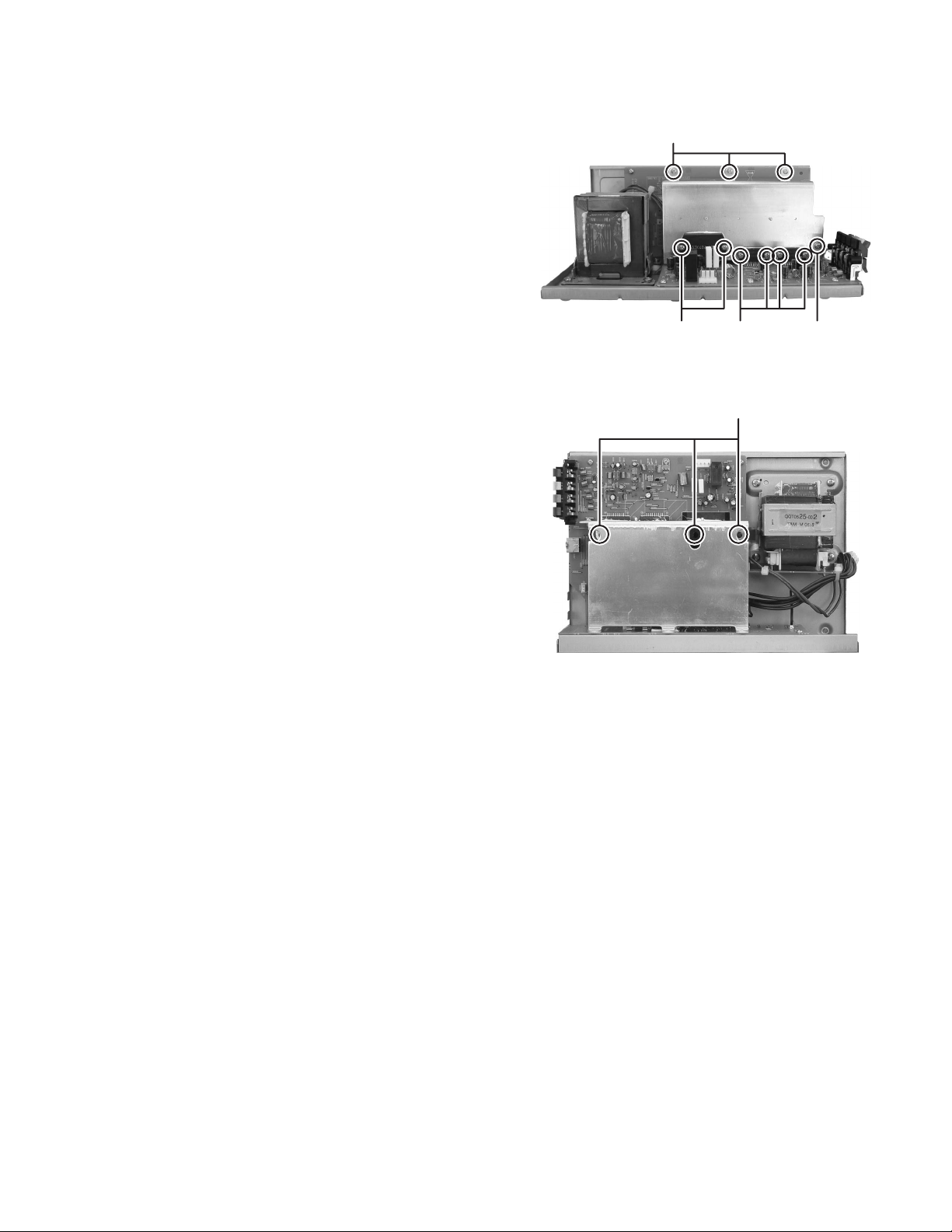
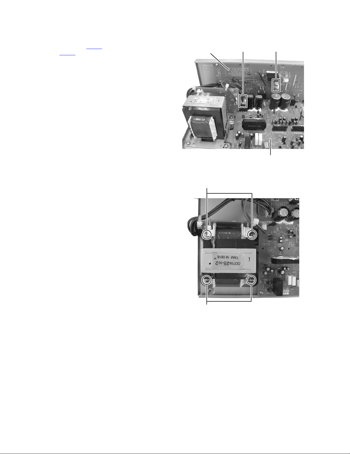
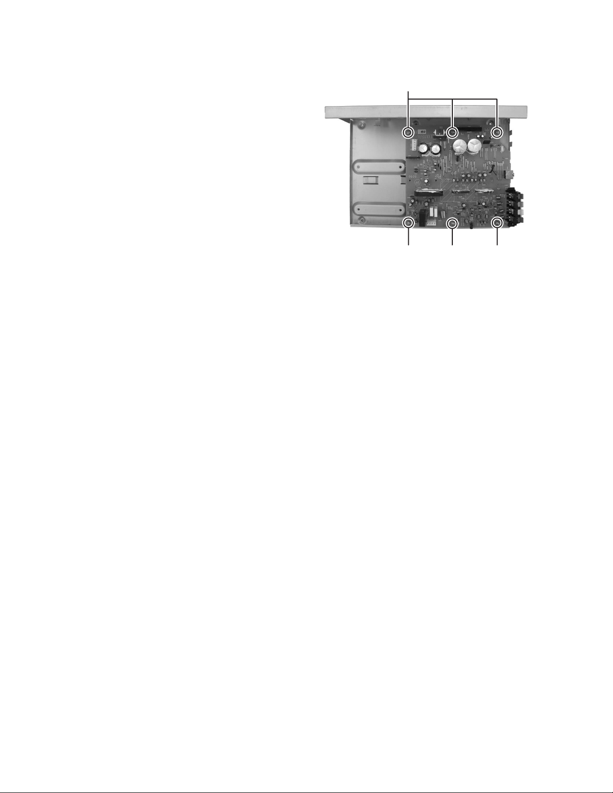
3.1.12 Removing the power supply board
(See Fig.22)
• Remove the side panel L, side panel R, top cover, front base,
audio board, tuner and rear panel.
(1) From the top side of the main body, disconnect the wire
from the connector CN901
(2) Disconnect the power code from the connector CN991
the power supply board.
(3) Remove the three screws W and screw W' attaching the
power supply board.
Reference:
When attaching the screw W', attach the barrier with it.
(4) Remove the screw X attaching the earth wire to the main
body.
Reference:
When attaching the screw X, attach the earth wire with it.
(5) Take out the power supply board from the main body.
3.1.13 Removing the video board
(See Fig.22)
• Remove the side panel L, side panel R, top cover, front base,
audio board, tuner and rear panel.
(1) From the top side of the main body, disconnect the card
wires from the connectors (CN601
board.
(2) Take out the video board from the main body in the direc-
tion of the arrow.
on the main board.
on
, CN603) on the video
CN991
W
W
Power supply board
X
W'
Video board
Fig.22
CN601CN901
CN603
(No.MB563)1-19
Page 20
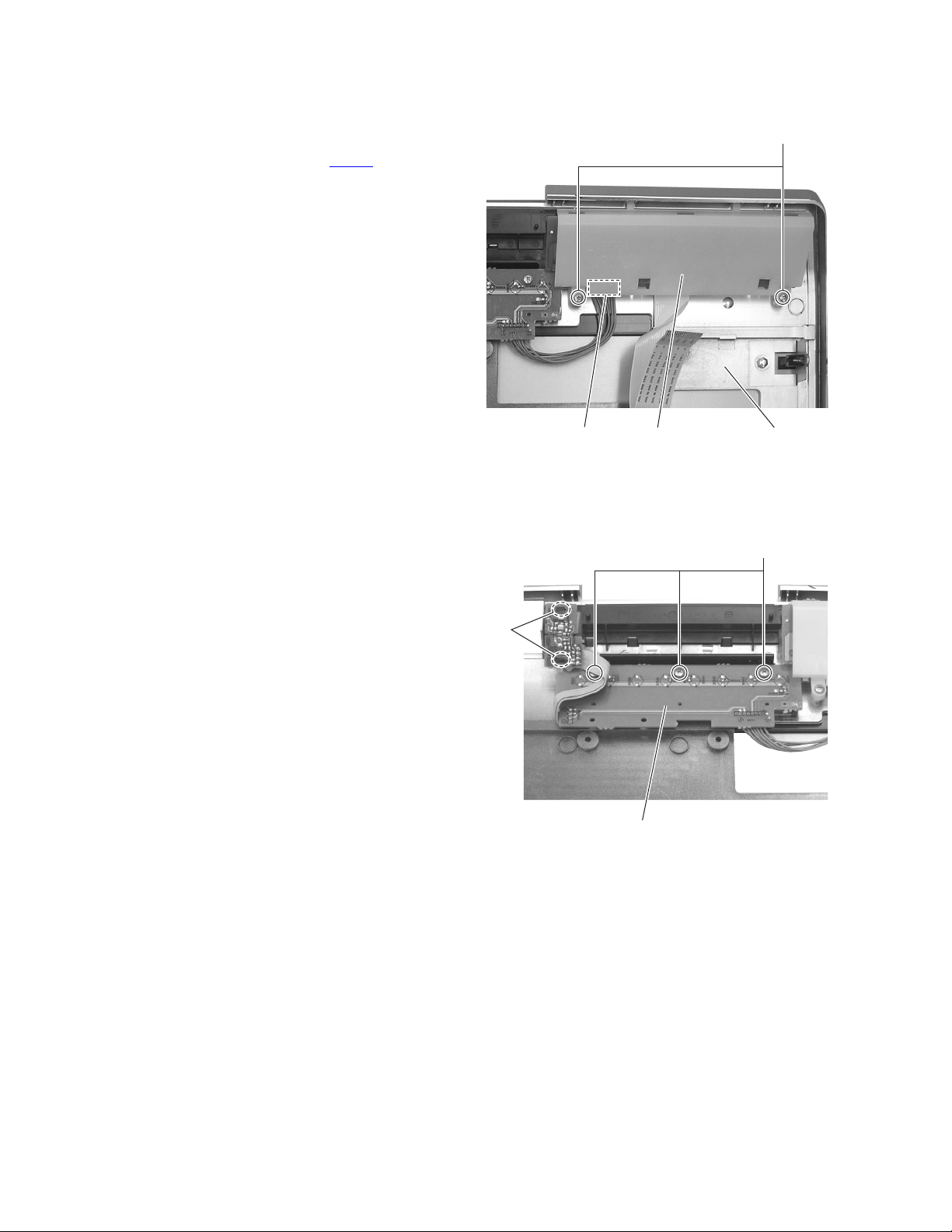
3.1.14 Removing the FL board
(See Fig.23)
• Remove the side panel L, side panel R and top cover.
(1) From the bottom side of the top cover, remove the two
screws Y attaching the top cover.
(2) Disconnect the wire from the connector CN562
board.
(3) Take out the FL board from the top cover.
on the FL
Y
3.1.15 Removing the key board
(See Fig.24)
• Remove the side panel L, side panel R, top cover and FL
board.
(1) From the bottom side of the top cover, release the two
joints d attaching the key board.
(2) Remove the three screws Z and then take out the key
board from the top cover.
d
FL boardCN562
Fig.23
Key board
Fig.24
Top cover
Z
1-20 (No.MB563)
Page 21
3.2 Powered subwoofer section
3.2.1 Removing the Power amplifier unit
(See Fig.1 to 3)
(1) Remove the six screws A attaching the Power amplifier
unit. (See Fig.1)
(2) Remove the three screws B attaching the Power amplifier
unit. (See Fig.2)
(3) The Power amplifier unit is drawn out on the way, discon-
nect the connector wire from speaker unit connected to
connector CN301
take out the Power amplifier unit. (See Fig.3)
of the AMP board assembly and then
AA
Fig.1
B
Fig.2
CN301
Fig.3
(No.MB563)1-21
Page 22
3.2.2 Removing the Rear panel with Fan
(See Fig.4, 5)
(1) Remove the one screw C and six screws D attaching the
Rear panel with Fan. (See Fig.4)
(2) Disconnect the connector wire from Fan connected to con-
nector CN303
of the AMP board. (See Fig.5)
D
D
DDD D
Fig.4
CN303
Fig.5
C
1-22 (No.MB563)
Page 23
3.2.3 Removing the Heat sink
(See Fig.6, 7)
(1) Remove the two screws E and four screws F attaching the
Power amplifier ICs. (See Fig.6)
(2) Remove the one screw G attaching the thermistor. (See
Fig.6)
(3) Remove the three screws H attaching the Heat sink. (See
Fig.6)
(4) Remove the three screws J attaching the Heat sink. (See
Fig.7)
H
E
FG
Fig.6
J
Fig.7
(No.MB563)1-23
Page 24
3.2.4 Removing the Power transformer
(See Fig.8, 9)
(1) Disconnect the connector wires from Power transformer
connected to connector CN102 of the Control board assembly and CN302 of the AMP board assembly. (See
Fig.8)
(2) Remove the four screws K attaching the Power transform-
er. (See Fig.9)
Control board
asembly
K
CN302 CN102
AMP board assembly
Fig.8
1-24 (No.MB563)
Fig.9
Page 25

3.2.5 Removing the Control board assembly
(See Fig.10 to 12)
(1) Remove the two screws L attaching the Control board as-
sembly. (See Fig.10)
(2) Remove the one screw M attaching the Control board as-
sembly. (See Fig.11)
(3) Disconnect the board to board connector connected con-
nector CN105
to AMP board assembly. (See Fig.12)
LL
Fig.10
M
Fig.11
Control board assembly
CN105
Fig.12
AMP board
assembly
(No.MB563)1-25
Page 26
3.2.6 Removing the AMP board assembly
(See Fig.13)
(1) Remove the one screw N and five screws P attaching the
AMP board assembly.
P
PNP
Fig.13
1-26 (No.MB563)
Page 27
3.3 DVD mechanism assembly
3.3.1 Removing the DVD module board assembly
(See Fig.1 to 3)
(1) Remove the two screws A attaching the clamper base.
(See Fig.1)
(2) Solder the solder part of DVD pickup. (See Fig.2)
(3) Disconnect the card wire from DVD mechanism assembly
connected to connector CN101
module board assembly. (See Fig.3)
(4) Remove the one screw B attaching the DVD module board
assembly. (See Fig.3)
Caution:
• Solder the short land section on the DVD pickup before dis-
connecting the card wire from the connector on the DVD
pickup. If the card wire is disconnected without attaching solders, the pickup may be destroyed by static electricity.
• When attaching the DVD pickup, be sure to remove solders
from the short land section after connecting the card wire to
the connector on the DVD pickup.
and CN201 of the DVD
A
B
CN201
DVD module board
CN101
A
Traverse mechanism assembly
DVD mechanism assembly
Fig.3
Fig.1
Solder short land section
Fig.2
(No.MB563)1-27
Page 28

3.3.2 Removing the Traverse mechanism assembly
(See Fig.4)
(1) Remove the four screws C attaching the Traverse mecha-
nism assembly.
C
C
CC
Fig.4
1-28 (No.MB563)
Page 29

3.3.3 Removing the pickup assembly
(See Fig.5 to 9)
(1) Remove the two rod springs pressing the guide shaft. (See
Fig.5)
(2) Remove the screw D and E attaching the spring holder.
(See Fig.6)
(3) Remove the read screw from traverse mechanism assem-
bly. (See Fig.7)
Caution:
When remove the lead screw, do not loss the middle
gear. (See Fig.8 and 9)
(4) Remove the bar spring pressing the shaft. (See Fig.8)
(5) Take out the pickup assembly from traverse mechanism
chassis by order. (See Fig.9)
(Shaft)
(T.Table)
Hook
(Bar spring)
Fig.8
Rod spring Rod spring
Fig.5
Spring holder
Fig.6
order 2
order 3
order 1
Fig.9
DE
Middle gear
Lead screw
Fig.7
(No.MB563)1-29
Page 30

3.3.4 Removing the Feed motor assembly
(See Fig.10)
(1) Remove the one screw F attaching the feed motor assem-
bly.
(2) Remove the feed motor wires from solder part of spindle
motor bard.
Splder part
3.3.5 Removing the Spindle motor assembly
(See Fig.11)
(1) Remove the two screws G attaching the spindle motor from
spindle motor board.
Middle gear
Lead screw
H
Spindle motor
Fig.10
G
F
1-30 (No.MB563)
Spindle motor
Fig.11
Page 31

3.3.6 Removing the Tray assembly
(See Fig.12, 13)
(1) Remove the one screw H attaching the shaft guide from
bottom side. (See Fig.12)
(2) Remove the two screws J attaching the shaft guide from
top side. (See Fig.13)
H
[bottom side]
Fig.12
J
Fig.13
(No.MB563)1-31
Page 32

SECTION 4
ADJUSTMENT
4.1 ATTENTION IN SERVICE OF DVD SECTION
(1) When pickup, Flash ROM ,DVD module board were changed, initialize EEPROM by all means.
(2) When full initialization was executed, execute learning with a DVD test disc by all means.
Test disc : VT-501, VT-502
Learning method : It is adjusted automatically by normal playback of a DVD disc.
4.2 TEST MODE
4.2.1 TEST MODE setting
Name of Key Function
Press STOP + PLAY key and
connect to AC
The DVD EJECT key is pushed
while pushing the STOP key
at the time of the P.OFF.
At P.ON, long press
STOP+POWER key 5sec.
4.2.2 REMOTE CONTROLLER TEST MODE setting
Name of Key Remocon code Content
STOP + 0 + POWER B330 Follow the SYSTEM_TEST MODE spec
It enters DVD TEST MODE.
The ON/OFF change of the TRAY LOCK mode is done.
It is made to advance in the clock at the --> 1 second of one minute.
FL and LED are lit. all COLD SET is done.
The mode clears long again for five seconds of STOP+POWER when done O.
(COLD SET is released. )
STOP + 1 + POWER B331 Follow the SYSTEM TEST MODE spec
STOP + 2 + POWER B332 Follow the SYSTEM TEST MODE spec
STOP + 3 + POWER B333 ERROR HISTORY indication
STOP +10 + POWER Follow the SYSTEM TEST MODE spec
STOP +>=10 + POWER B33F Follow the SYSTEM TEST MODE spec
4.2.3 DVD communication
TEXT indication
MP3 FileName
indication
TEST mode
TEST mode
>>| Key is pushed
Initialization
>>| Key is pushes
long (2seconds)
FULL initialization
|<< Key is pushed
Press MENU Key
Press MENU Key
Press MENU Key
C
S
C
C
C
S
S
C
S
S
C
S
S
C
C
C
S
C
C
S
C
B33E
0 1 2 3 4 5 6 7 8 9 10 11 12 13 14 15 16 17 18 19
9A 00 00
AE 00 00
0 1 2 3 4 5 6 7 8 9 10 11 12 13 14 15 16 17 18 19
94 00 02
9C 1F
97 05
A6 05
AA 09
9C 06
AA 01
AA 09
9C 06 01
AA 01
AA 09
9C 1F 06
9C 1F
97 06
A6 06
9C 1F 02
97 04
A6 04
9C 1F 03
00
** **
** **
00
** **
** **
01
** **
** **
**
Remarks
Request from File name, 0th character
Display information
Remarks
TEST MODE specification by INITIAL command
Mode state report (DELIVER INFO)
Destination, Region number demand
Destination, Region number information obtaining
Study state initialization information display to FL
EEPROM Initialization
Initialization end
Study state initialization information display to FL
EEPROM Initialization (FULL)
Initialization end
Study state initialization information display to FL
Mode state report (DEVICE KEY WRITE)
14.Refer to the device key writing specification
Mode state report (DEVICE KEY INFO)
DEVICE KEY CHECKSUM REQ
CHECKSUM is displayed in FL
Mode state report (VERSION INFO)
Micom Version number demand
FL all on mode
1-32 (No.MB563)
Page 33

TEXT indication
r
Press MENU key
Press 10key [1]
Press 10key [2]
Press 10key [3]
Press 10key [4]
Press 10key [5]
Press 10key [6]
Press 10key [7]
Press 10key [8]
Press 10key [9]
Press 10key [10]
Press 10key [0]
Press 10key [+10]
Press STOP key
Press PLAY key
0 1 2 3 4 5 6 7 8 9 10 11 12 13 14 15 16 17 18 19
C
9C 1F 04
C
9C 11
C
9C 12
S
AA
9C 13
AA
9C 14
AA
9C 15
AA
9C 16
AA
9C 19
AA
9C 18
AA
9C 1B
AA
9C 1C
AA
9C 1D
AA
9C 1A
AA
9C 03
9C 1E
AA
** ** ** **
** ** ** **
** ** ** **
** ** ** **
** ** ** **
** ** ** **
** ** ** **
** ** ** **
** ** ** **
** ** ** **
** ** ** **
** ** ** **
C
S
C
S
C
S
C
S
C
S
C
S
C
S
C
S
C
S
C
S
C
C
S
Remarks
Inform the MODE condition
Disc startup and through playback
(Playback starts from start position)
Presence of WOBBLE
Indicate to FL
Port check mode
Indicate to FL
CD_LD on & indicate laser current
Indicate to FL
DVD_LD on & indicate laser current
Indicate to FL
DVD SL x 1 jitter measurement mode
Indicate to FL
Backup memory contents (0x00-0x63)
indication (BWD)
Indicate to FL
Backup memory contents (0x00-0x63)
indication (FWD)
Indicate to FL
Indicate temperature sensor value (AD value)
Indicate to FL
DVD-DL, SL prescribed search & measure jitter
Indicate to FL
Switching the monitor output
Indicate to FL
Initialize the backup memory contents
Indicate to FL
Disc stop, LD off
Disc playback
Indicate to FL
4.3 ERROR HISTORY
4.3.1 Outline
EEPROM use 256byte, when an abnormal state is generated, the factor is written in EEPROM.
Worth of a history is left for each item 16 times.
It displays by the TEST code of remote control, and each address according to the key of the display of ERROR HISTORY.
4.3.2 ERROR writing
(1) ERROR information
No. Item Count
SAFETY Number
1
AD value
2 P.OFF timeout factor
Value of writing Writing condition
16 SAFETY abnormal No.
16 AD value at time
16 Factor of failure
3 DVD 16 Factor of failure
4 16
P.OFF factor Factor of power off
Others
5
When detectiong of SAFETY
error, writing SAFETY number
and AD value
Time out of power OFF process Mechanical and module failure.
Error with DVD Module failer
When starting power off process User operation
Guessed factor
Power circuit failure.
Damege of card wire.
Missing key operation.
Damege of card wire.
(2) EEPROM writing timing
When abnormality occurs respectively, the value of the generated item is rewritten.
The writing starting address is assumed to be the latest one, and even the 16th byte writes the history in new the orde
at the following.
The writing method does the batch writing 16 bytes with PAGE WRITE.
(3) EEPROM clear condition
When COLD SET is fixed by remote control code [ 0 ]+[ ]+[POWER] receive, the ERROR HISTORY part is
cleared (ALL0x00).
(EEPROM clear not done by COLD START process)
[ 0 ] + [ ] + [POWER]
Receive
EEPROM
E.HISTORY clear
COLD
process
(No.MB563)1-33
Page 34

4.3.3 Reading the ERROR HISTORY
The reading method is done by the following ways.
No. Operation Indication System micon processing
Receive the remocon code.
1
[STOP]+[ 3 ]+[POWER]
Address change to 1 by <<, >> key
2
of the remote controller.
Address change to 0x10 by |<<, >>|
key of the remote controller.
Indication is start address to 00 then
indicate step by 1 byte.
operation exp.) address 00 indicating
ER I OFNR
00 01:
address data
Read out the ERROR HISTORY
information from EEPROM.
Read out the ERROR HISTORY
information from EEPROM.
Cancel the mode by remocon code.
3
[STOP]+[ 3 ]+[POWER]
4.3.4 ERROR details
SAFETY Number
AD value
P.OFF timeout factor
DVD
P. O F F
Others
Press >> key
Press >>| key
Press << key
Press |<< key
Press |<< key
01 05:
10 21:
0F 11:
00 01:
F0 00:
SAFETY number at SAFETY occur.
1~5 (SAFETY watch umber difference by model)
AD value at SAFETY occur
00~FF
Factor that was not able to be power off.
DVD, CD TIMEOUT
10
MECHA CLOSE TIMEOUT
70
Others
90
Abnormal factor concerning DVD
MECHA CLOSE TIMEOUT
70
MECHA OPEN TIMEOUT
71
Factor that was power off
NORMAL
10
AUTO STANDBY
20
SLEEP
30
TIMER
40
Return to normal function indication.
1-34 (No.MB563)
Page 35

SECTION 5
TROUBLESHOOTING
This service manual does not describe TROUBLESHOOTING.
(No.MB563)1-35
Page 36

Victor Company of Japan, Limited
Audio/Video Systems Category 10-1,1chome,Ohwatari-machi,Maebashi-city,371-8543,Japan
(No.MB563)
Printed in Japan
VPT
Page 37

SCHEMATIC DIAGRAMS
NETWORK MEDIA SYSTEM
DD-8B,DD-8E,DD-8EN,DD-8EV,DD-8EE
DD-3B,DD-3E,DD-3EN,DD-3EV,DD-3EE
CD-ROM No.SML200611
SP-DD8S
SP-DD8F SP-DD8F
Contents
Block diagrams
Standard schematic diagrams
Printed circuit boards
CA-DD8
Lead free solder used in the board (material : Sn-Ag-Cu, melting point : 219 Centigrade)
SP-PWDD8
(Only for DD-8 and DD-3)
SP-DD8S
CA-DD3SP-DD3F SP-DD3F SP-PWDD3
2-1
2-2
2-14 to 18
COPYRIGHT 2006 Victor Company of Japan, Limited.
No.MB563SCH
2006/11
Page 38

In regard with component parts appearing on the silk-screen printed side (parts side) of the PWB diagrams, the
parts that are printed over with black such as the resistor ( ), diode ( ) and ICP ( ) or identified by the " "
mark nearby are critical for safety.
Page 39

Block diagram
<Main body section>
DVD servo section
A, B, C, D, E, F, RF+, CDPD, DVDPD
DVD
traverse
mechanism
HDMI
TERMINAL
RJ45 LAN
TERMNAL
COMPONENT
VIDEO OUT
SCART
TERMINAL
Power Supply section
CN991
AC IN
CN101
FM+/WOUT
VOUT
CN201
UOUT
COM
TX_HPD, TX_SCL, TX_SDA
J801
Network section
TD+/-, RD+/TCT, RTC
LEDGK
J8101
LEDYK
3.3V
Video Jack section
Y, Pb, Pr
B
G
J6401J6701
R/C
IC981
SWITCHING
REGULATOR
D9010
DIODE
BRIDGE
LD(CD)
LD(DVD)
F+/T+/-
IC201
DRVER
TX0+/TX1+/TX2+/TXC+/-
HDMI TX
IC811
ETHERNET-LAN
TRANSCEIVER
X8101
25MHz
IC831
FLASH
ROM
IC821
SDRAM
IC841
3.3V REG.
BLANKING
FUNCTION
ADCD
ADDVD
Q101,Q103
LASER DRIVER
SPDRV, TRSDRV, FODRV, TRDRV
DRVMUTE, LCS2, SPNP
IC802,Q801 to Q803
LEVEL CONVERTER
H_D0 to 11, H_DE, H_IDCK, H_MCLK
IC801
H_HSYNC, H_VSYNC, H_SPDIF
H_CSCL, H_CSDA
H_RESET
IC510
EEPROM
TXD0 to 3
RXD0 to 3
MDC, MDIO
COL, CRS
TXCLK, RXCLK
RXDV, RXER
TXEN, TXER
X8001
10MHz
CE
P0_0 to 31
CS, WE
CLK, CKE
CAS, RAS
1.2V
LANVCC2
CV/Y
IC601
VIDEO
DRIVER
Q6451
IC801
NETWORK
PROCESSOR
IC851
1.2V REG.
C, V, Y1, Y2, CB, CR
V_MUTE1, V_MUTE2
V_YCMIX, V_LPF, V_RGB
BLANK
Q6452
VS1
VS3
Q6453
Q6454
D9601
VDISP
D9501
T9901
D9401
TRANS
D9301
D9201
CDLDO
DVDLDO
27MHz
HPD, DSCL, DSDA
HA0 to 2, HD0 to 15
HCS1, HCS3, HRD, HWR
HIRQ, HIORDY
HRST, CPURST
P5_2
CN351
CN801
SYS_RST
DA0 to 2
DD0 to 15
CS0, IN_TF
DIOR, DIOW
IRQR, IORDY
IDE_GP0
IDE_GP1
IDE_RST
P5_2
LANVCC1
AUDIO_L_IN
AUDIO_R_IN
5V
6V
9V
12V
LA0 to 21, LD0 to 7
LOE, LCS3, LWRLLB
MA0 to 11, MDQ0 to 15, BA0, BA1
X301
TRVSW
IC301
Phoenix
DQM, DSCK, NCS, NRAS, NCAS, NWE
LINE_OLO/R
AIN, TWS, MCLK
TBCK, DACPDN
TSD0 to 2
LCS1
LD0 to 7
LA4, LA5
LWRLLB
DVD loading
section
LOADING MOTOR
&
TRAY SWITCH
CN1
CN471
TRAY_OPSW
TRAY_CLSW
TRAY+/-
LOPEN
IC471
LCLOSE
TRAY
CN803
W481
DRIVE
EEPROM
IC431
E2CLK
E2DATA
S5V
IC432
Q4321
RESET,
BACKUP
V_LPF
CN603
CN463
CN601
CN461
CN901
W491
V_RGB
V_MUTE1
V_MUTE2
V_YCMIX
X4201
8MHz
C, V
Y1, Y2
CB, CR
VS1, VS3, BLANK
VDISP
5V
6V
9V
12V
System Control section
IC309 to IC312
A5V
IC705
A5V
REG.
A6V
INH
RST
SYSTEM
IC509
FLASH ROM
IC706
AUDIO LPF
IC704
ADC
IC701 to IC703
DAC
ML0 to 2, MC, MD, DACPDN
DECODER
D1.2V
TX5V
IC302
1.2V
IC806
REG.
TX5V
REG.
D2V
US6V
D4V,D6V,US6V
CN801
CN473
UCS, DVD_CK
DVD_U2SDT2
FDVD, S2UDT
DVD_CS, DVD_RST
KEY1, KEY2, POWER_KEY
REMOCON, STANDBY, ILLUMI
FLBK, FLCLK, FLSTB, FLDATA
TUNER-CE, TUNER-DTI
IC401
MICON
TUNER-CK, TUNER-DTO
RDS_CTL, RDS_INT, RDS_DATA
AVC_IN
AVC_OUT AVVLR
SW_PON
LOMUTE, LEVEL
SIG, FTU, SW_LEVEL
LINEOUTJACK, LINEINJACK
SMUTE, LRMUTE
VOL_CK, VOL_DT
HPMUTE, HPJACKIN
A12V TU9V
FTU
SAFETY3
FLPOWER
VDISP
CLIMIT
D6V
IC505
OUTL/R
AINL/R
FAOUTL/R, RAOUTL/R
CAOUT, SWAOUT
LRMUTE
S3.3V
IC305
3.3V
REG.
D4V
DVD_BUSY2
DVD_CK2, DVD_U2SDT
SDRAM
1.8V
IC804
1.8V
REG.
D4V
DVDPWR
LEVEL
Q4611
AV
COMPULINK
Q4621
SW_PON
Q4622
SW-PON
Q4401 to Q4404
TU9V REG.
Q4971 to Q4973
9V
FL SW
Q4961 to Q4963
VH SW
USB_PO, USB_NO
5V REG.
3.3V
IC805
3.3V
REG.
D4V
D2V,D4V
S5V,M9V
CN701
CN472
IC425
SHIFT
IC306
FDAC
VDAC
YDAC
CDAC
UDAC
IDAC
SPDIF_I
SPDIF_O
S2UDT
U2SDT
UCS
SCLK
SCS
CPURST
TU9V
AUDIO_L_IN
AUDIO_R_IN
F+/-
VH
VBUS
A6V
TU-L
TU-R
TX
RX
SAFETY1
FDVD
SAFETY2
CN704
CN702
CN451
CN441
Tun er
CN421
CN429
CN422
Pack
W502 W501 CN204
Front Jack section
Key SW section
S5501 to S5507
KEY MATRIX
KEY1, KEY2
FL display section
CN561
F+/-,VH
US5V,M9V
HPMUTE
LOMUTE
HPJCAKIN
LINEIN1JCAK
LINEOUTJACK
OUT-L/R
OUT-SL/SR
OUT-C
OUT-SW
CN201
ADIN-L/R
DMIXL/R
LRMUTE
3.3V
A5V
W203
US5V
CN202
CN428
Q4951 to Q4953
S5V REG.
Q4921,Q4922
A12V SW
Q4941,Q4942
SW6V REG.
LOMUTE, LINEOUTL/R
S5511
POWER SW
KEY1, KEY2
POWER_KEY
REMOCON
HPL/R
IC231,Q2032,Q2804
HP AMP/MUTE
LINEOUTL/R
LINEIN1L/R
IC221
Q2021
to Q2025
PLINK
DETECT
AMP.
SIG
LEVEL
SCARTL/R
TU-L/R
S5V,US5V5V
A12V12V
A6V,SW6V6V
LINEIN1L/R
POWER KEY
W551
CN562
REMOCON
IC561
IC200
SIG. SEL.
VOL AMP.
IC205
SELECT
TUNER/LINE
Q5102,Q5202
LINE IN BUFFER
Q5002,Q5101,Q5201
LINE MUTE
HPL/R, HPJACKIN
Illumination section
FW581
FW552
STANDBY
ILLUMI2
Q5601
Q5602
STANDBY
ILLUMI
D5661,Q5661
ILLUMINATION LED
HP_OUT_L/R
LOUT
ROUT
SLOUT
SROUT
COUT
SWOUT
VOL_CK
VOL_DTA
INL2, INR2
FTU
Q4931,Q4932
9V
M9V REG.
Q4851
3.3V REG.
VBUS
LINEIN1JACK
LINEOUTJACK
D5801,D5802
STANDBY, ILLUMI2
FLBK
FLCLK
FLSTB
FLDATA
ILLUMI
Audio section
IC201,Q2801
Q2805,Q2806
L/R AMP/MUTE
IC202,IC203
Q2803,Q2807
SL/SR/C
AMP/MUTE
IC204
Q2601,Q2808
SW AMP/MUTE
SMUTE
J5404 J5401J5301J5302
D-/+
LED
DI561
FL DISPLAY
SW_PON
SW_LEVEL
Q2101
Q2201
M9V
3.3VS5V
USB
LINE
IN 1
LINE
OUT
HEADPHONE
OUT
L
R
SL
SR
SYSTEM
J2102
SYSTEM
CONN.
SW
J2101
L-IN
R-IN
LINE IN 2
IC261
TX
DIGITAL
OUT
IC271
RX
DIGITAL
IN
<Speaker AMP section>
Amplifier section
IC301
L
Q3011 to Q3015
R
L/R POWER
AMP &
PROTECTOR
SL
SR
IC302
Q3021 to Q3025
SL/SR POWER
AMP &
PROTECTOR
Used for
AX-PWDD3
SW LEVEL
Q3661,Q3662
SUBWOFFER
CONTROL
SW
IC303,Q3601
SW POWER
PROTECTOR
SP RELAY
P.ON CONT
+D12V
Q3921
+D12V REG.
-VL
+/-A12V
Q3931,Q3941
+/-A12V REG.
+/-VL
Control section
PROTECT
DC DETECT
Q1301 to Q1305
PROTECTOR
Q1201,Q1202
LOW VOLTAGE
DETECTOR
Q1101
to Q1105
POWER
CONTROL &
PROTECTOR
RY101
RELAY
LEVEL
IC304
OP AMP
AMP &
RY301
RELAY
Q3811
Q3801
Q3802
FAN
MOTOR
DRIVER
+D12V
AC ON
Q1401
to Q1407
MUTE
CONTROL
BRIDGE
BRIDGE
AC ON
SP RELAY
CN102
CONN.
AC IN
J3001
CN101
PROTECT
DC_DETECT
CN304
CN105
SAFETY
P.ON CONT
J3002
SPEAKER
CN301
CN303
+/-VH
D3911
DIODE
+/-VL
D3901
DIODE
D3902
D3903
DIODE
W902
FLOUT
FROUT
SLOUT
SROUT
SUB
WOFFER
& LED
FAN
MOTOR
CN302
W951
T1001
POWER
TRANS.
2-1
Page 40

Stabdard schematic diagrams
Primary section
!
!
2
1
CN991
QGA7901F2-02
123
EP991
QNZ0136-001Z
Ver.J
120V 60Hz
Ver.B/E/EN/EV/EE
230V 50Hz
Ver.UT/US/UX/UW
110-240V 50/60Hz
Ver.UF
220V 50Hz
Ver.A
240V 50Hz
*
F9901
C9909
C9901
32
!
C9907
!
REG.IC
!
IC981
MIP4170MDSLJ
0.001/AC250V
0.068/AC275V
0.001/AC250V
NI
!
R9902
C9903
L9901
QQR0908-001
4
C9908
1
0.068/AC275V
!
NI
C9902
NI
!
SWITCHING
D
VDD
S
VCC
TR
FB
HS991
LV40057-001A
Ver.
*F9901
*C9904
*C9911
ADDRESS
(2,A)
(4,B)
(5,B)
(8,C)*D9502
REF No.
D9010
!
DI106
3
1
3.3M
4
R9901
!
5.9V
19.8V
3.4V
1.7V
1234567
J
QMFZ059-1R0-E
(1A-250V)
---- ----
QETM2DM-107
NOT USE
C9801
220p/2000
C9802
2
R9906
C9803
C9804
D9802
C9805
R9802
R9905
1M
TH991
NI
0.1/50
B1332
R9904
1M
R9907
1M
1M
15p/50
0.1/50
MA704A-X
3.3kR9801
4.3K
330p/50
A/B/E/EN/EV/EE/UF
QMFZ059-1R0-E
(T1AH 250V)
QEZ0665-476
(47/400)(100/200)
C9904
*
NOT USE USE
NI
Primary GND.
W491
QJK048-120802-E
1
2
3
4
5
6
7
8
9
10
11
12
LVA10677-A1
CN901
QGA2536C1-12
1
2
3
4
5
6
7
8
9
10
11
12
KTA1504/YG/-X
39.2V
NI
C4965
KTA1273/Y/-T
12.6V
1k
R4921
NI
C4926
Q4961
C4971
Q4921
Q4922
KRC103S-X
NI
D4961
Q4962
KTC3875/YG/-X
4.3K
R4962
NIR4933
R4932
NI
11.8V
39k
R4922
38.5V
4.3V
1.3k
22KR4931
4.3V
30.7V
12.5V
0V
R4961
4.8V
C4975
22/50
NI
C4943
C4932
KTC3875/YG/-X
D4965
R4971
2.2K
C4921
Q4963
KRA111S-X
10
C4942
NI
C4972
1.5/25
LVA10677-A2
POWER PWB
T9901
QQS0393-001
C9910
NI
C9905
NI
0.0022
B1299
/2000
NI
R9804
IC971
KIA431A-T
OMF 2W
68k
14
3.69V
68k
R9903
D9902
20NFA60-FC5
D9903
20NFA60-FC5
!
FR
R9803
(1/4W)
47k
R9805
2.476V
1
23
!
C9911
47/400
*
22/50
C9807
C9703
!
0.001/AC250V
C9906
D9801
1SS244-T2
47/50
C9808
PC991
!
PC123Y22FZ
0.67V 4.73V
C9806
0.1/50
32
UT/US/UX/UW
QMFZ059-2R5-E
(T2.5AH 250V)
QEZ0688-107
(100/400)
----
1
2
3
4
27
9
7
R9701
300
R9702
4.7K
NI
R9703
R9704
1K
C9930
0.1/50
R9708
J :U.S.A.
C :CANADA
B :GREAT BRITAIN
UW:BRAZIL/MEXICO/PERU
UY:ARGENTINE
UJ:USA MILITALY BASE
A :AUSTRALIA
US :SINGAPORE
UG:TURKEY/EGYPT/SOUTH AFRICA
UN:INDONESIA
UX:SAUDI ARABIA
UT:TAIWAN
UF:CHINA
GND
!
NI
R9705
2.7K
R9706
4.7K
R9707
7.5k
NI
R9709
VERSION CODES
Q9701
!
C9601
100p/1000
10
D9601
FR104S-T5
11
12
13
5V
14
6V
9V
15
17
12V
16
NI
R9710
NI
D9701
NI
R9303
NI
NI
C9701
R9601
L9601
10
FR
SB360-F82
UF202G-F26
!
0.22u
(1/4W)
C9504
0.1/16
C9302
L9401
22u
22uL9301
1.5/25
L9201
R9602
10u
150K
470/10
C9503
C9402
1.5/25
B1631
MF
220/16
C9303
NI
Q9301
33k
R9201
SOURCE:DVD/CD.DVD STOP.
39/50
C9602
C9501
100p/50
!
D9501
SB360-F82
D9502
*
C9401
220p/50
!
D9401
C9301
D9301
UF202G-F26
C9204
220p/50
!
NOTES:
1.VOLTAGES ARE DC-MEASURED WITH A DIGITAL VOLT METER
OR OSCILLOSCOPE WITHOUT INPUT SIGNAL.
CONDITION POWER-ON.
2.UNLESS OTHERWISE SPECIFIED.
ALL RESISTANCE VALUES ARE IN OHMS.
ALL INDUCTANCE VALUES ARE IN H.
ALL CAPACITANCE VALUES ARE IN F.
"NI" MARKING PART IS NOT USED.3.
D9201
FR104S-T5
220p/50
4.95V
C9502
C9404
C9201
220p/50
1000/10
820/16
C9304
C9203
10.8V
C9603
6.4V
560/25
22/50
L9501
820/16
22u
12.6V
Parts are safety assurance parts.
When replacing those parts make
C9403
R9301
NI
C9305
u IS uH.
QNZ0136-001Z
220/16
NI
1/16W, 5%.
P IS pF.
R9302
EP961
VDISP
5V
6V
9V
12V
NI
C9202
220/16
123
30.6V
NI
D4962
6
7
8
4.85V
NI
C4953
Q4941
RTR030P02-X
6.4V
22k
R4941
0V
NI
Q4942
KRC103S-X
Q4931 RSS090N03-X
10.8V
DGS
Q4932
0.6V
10.7V
10.2V
4.8V
4.7/50
C4922
100/16
C4962
R4966
2.2K
DGS
9.4V
C4951
11.4V
R4934
1SS133-T2
Q4972
KTC3875/YG/-X
(1/2)
NI
!
R4951
6.4V
DGS
R4942
9.7V
1k
4.3V
27k
R4963
2
4.82V
Q4951
RSS090N03-X
10k
R4952
22k
R4953
0.1/16
10k
4.3V
C4931
1.2V
7V
Q4971
KTA1273/Y/-T
560
R4972
L4961
10u
CP495
ICP-N15-T
3
9.4V
330k
C4941
D4963
NI
NI
C4963
Q4952
KRA104S-X
Q4953
KRC104S-X
R4943
0.1
NI
D4964
R4935
360
R4973
1.9V
R4975
270
0V
56K
R4944
47K
MTZJ9.1A-T2
4.7k
750
R4974
CLIMIT1
VH
VH
C4964
0.1
FLPOWER
FLGND
MICOM
REMOCON
US5V
S5V
SAFETY1
GND
FDVD
SW6V
SAFETY2
GND2
M9V
MGND
F+
F-
SAFETY3
A12V
A6V
AGND
STB_LED
HP_MUTE
AUX_MUTE
V5V
S5V
D4V(HDMI)
D2V
opt in/out
SW6V(HDMI)
D6V
M9V
FL
HP_AMP
VOLIC
MIX
BUFFER
TUNER
LVA10677-A1 (2/2)
TO MICOM BLOCK
CP496
(B1168)
NI
56K
R4955
C4952
0.1/16
9.5V
R4954
1k
56K
C4973
0.033
Q4973
KTA1273/Y/-T
C4974
100/16
R4956
R4976
R4977
56K
33K
4.3V
C4933 NI
2.6V
SWA12V
A6V
100/16
C4925
sure to use the specified one.
2-2
Page 41

System control section
LVA10677-A1
MICOM PWB
CLIMIT1
VH
FLPOWER
FLGND
US5V
S5V
SAFETY1
GND
FDVD
SW6V
SAFETY2
GND2
M9V
MGND
F+
LVS10521-001A
F-
LVA10677-A1 (1/2)
SAFETY3
TO POWER SUPPLY
A12V
A6V
AGND
NI
-+
FAN MOTOR
Q4501
NI
2
1
CN453
NI
Q4502
NI
NI
NI
D4501
C4502
R4504
NI
R4503
TO DVD
TO LAN PWB
LVA10679-A1
(2/2)
D4801
10EDB20-T4
D4804
10EDB20-T4
22k
R4509
KTC3875/YG/-X
Q4505
4.8V
0V
R4508
22k
R4507
22k
C4154
NI
0.01
C4156
R4501
NI
NI
FAN_SW1
FAN_SW2
R4502
NI
C4501
NI
NI
C4169
NIC4152
B1016 0
B1017 0
B10110B1010 0
C4153 NI
LANVCC2
GND
LANVCC2
7654321
R4801
CLIMIT
Q4201
NI
KTC3875/YG/-X
8MHz
X4201
Q4202
NI
KTC3875/YG/-X
CLK
U2SDT
S2UDT
RESET
VDD
DGND
CN401
QGF1205C2-06
DVD_CK
DVD_CK2
3.3V
4.75V
IC425
0
B10120B10130B1014
CN803
LANVCC1
GND
GND
LANVCC1
2.2
2W
C4203
NI
C4202
R4201 NI
NI
C4201
QAX0246-001Z
C4204 NI
R4203 NI
R4204
NI
C4206
NI
FOR FLASH
6
5
4
3
2
1
QQR0621
(B4165)
K4001
QQR0621
-001Z
(B4112)
220
R4251
K4002
0.1
C4251
7654321
TC74VHCT08AF-X
LEVEL SHIFT
EP411
QNZ0136-001Z
123
W481
QJK052-072602-E
A12V
A6V
R4202
NI
NI
321
C4205
NI
-001Z
C4007
100/16
141312111098
3.3V
4.75V
3.3V
4.75V
4.75V
DVD_BUSY2
DVD_U2SDT
D4831
1SS133-T2
US5V
C4003
0.1
DVD_U2SDT2
0
B1015
D4834
1SS133-T2
S2UDT
DVD_U2SDT2
DVD_CS
UCS
QNZ0136-001Z
SAFETY1
SAFETY2
SAFETY3
EP401
123
D4836
1SS133-T2
DVD_CK
D4835
1SS133-T2
39k
R4833
10kR4081
10kR4082
*
R4005
C4001
0.1/16
C4002
0.1/16
R4098 1k
R4099 1k
R4100 1k
R4013
VOL_DT
VOL_CK
R4009 0
R4011
470
R4089
470
BACKUP
AND
DETECT
RESET
F+
F-
123456789
F-
27k
R4834
*
*
R4080
R4004
*
R4003
C4009
0.01/50
10k
10k
2.2k
R4012
R4010
VH
FLBK
VH
GND
US5V
FLGND
TO FRONT PWB
LVA10678-A5
LVS10522-002A
C4011
R4093
R4094 1k
R4095 1k
R4096 1k
R4097 1k
0.01/50
C4008
C4010
0.01/50
R4006 1k
R4007 47k
R4008 1k
R4014
R4015
NI
FLCLK
FLBK
0.01/50
C4324
FLSTB
FLCLKF+FLSTB
DD1:FMU-MB3-21M
DD3/8:FMU-MB3-1M
(USB&HDMI POWER)
3.3V REG
Q4851
R4852
KTC3203/OY/-T
10
4.6V
220
R4851
4.3V
C4851
100/16
D4852
MTZJ4.7A-T2
TP408
TP409
10k
R4083
C4006
0.01
R4079 1k
4.9V
99
100
+BCTL
DAVDD
4.9V
VREF-
12345678910111213141516171819202122232425
2.2k
0V
SAFETY4
4.9V
VERSION1
4.9V
VERSION2
0V
KEY1
4.9V
KEY2
4.9V
SAFETY1
4.9V
SAFETY2
4.9V
SAFETY3
4.9V
VREF+
4.9V
VDD
2.3V
OSC2(8MHz)
2.3V
OSC1(8MHz)
0V
GND
XI
4.8V
XO
0V
MMOD
4.8V
VOL_DATA
0V
NC
4.8V
VOL_CLK
4.7V
DVD S2UDT/TX
4.9V
DVD U2SDT/RX
4.7V
DVD CK/CLK
4.7V
100
DVD SCS
4.7V
BEAT
REMOCON
UCS
26272829303132333435363738394041424344454647484950
1k
R4016
R4017
(FOR FLASH)
KRC111S-X
2.2/50
R4324
10k
4.85V
0.01
0V
FLDATA
101112131415161718
FLDATA
34
STANDBY_LED
STANDBY
C4321
12
VCC
NC
POWER_KEY
ILLUMI
R4323
4.85V
RST
GND
0V
REMOCON
REMOCON
POWER_KEY
100k
IC432
S-80840CNNB-G-W
KEY1
KEY2
KEY2
KEY1
CN561
Q4321
0V
D4322
1SS355-X
M9V
GND
DGND
DGND
D6V
DGND
TH or D4V
D6V
123456789
R4853 NI
R4854 0
3.6V
C4852
100/16
FDVD
R4076 1k
R4078 1k
R4074 1k
R4075 1k
R4077 1k
VS3
VS1
FDVD
DAVSS
FLPOWER
FLPOWER
RDS_INT
POWER_KEY
RESET/RST
HDMI CECI
NC
VDD2/FLASH-VDD
1k
R4021
2.2k
100
2.2k
R4018
R4102
10k
NIR4312
10k
R4322
R4321
4.9V
1k
C4323
C4322
2.2/50
HDMI CEC
100
R4505
ILLUMI_DIMMER
NI
R4506
C4503
220/16
CN451
QGF1036C2-19
19
GND
HDMICEC
SW6V
D4V
QGF1036C2-09
HDMI_CEC
R4073 1k
R4072 1k
R4071 1k
BLANK
V_YCMIX
V_MUTE1
MN101C49KRC
SYSTEM MICOM
DVD RESET
HDMI CECO
INH
R4019 NI
R4103
R4104 100
DVD_RST
0.01
R4314
Q4311
CN473
R4069 1k
R4070 1k
V_LPF
IC401
STANDBY_LED
1k
R4020
HDMI_CEC
10k
D4311
NI
NI
FAN_DET1
R4068 1k
V_RGB
V_D2IP
V_MUTE2
NTSEL(RGBSEL)
ILLUMI_DIMMER
ILLUMI_ON/OFF(NC)
10k
1.8k
R4090
R4022
NI
R4091
NI
(WITHOUT FLASH)
R4313
R4311
R4064 100
V_S2
V_S1
E2DATA
VPP/FLASH-VSS
NI
1k
R4024
R4023
0
C4302 10/50
RDS_CTL
E2WP
C4301 0.01
R4063 1k
1k
R4025
TUNER_CE
E2CLK
R4062 1k
TUNER_DTO
FLDATA
100R4026
R4060 1k
R4061 1k
0V
0V
TUNER_CK
FLSTB
100R4027
100R4028
100
R4302
0V
4.85V
8765
VCC
A1
A0
0V
0V
R4059 100
0V
TUNER_DTI
FLCLK
100R4029
4.8V
WP
A2
0V
R4058 NI
0V
RDS_DATA
FLBK
R4045 1k
R4301
4.8V
SCL
4321
0V
5.6kR4725
NIR4727
4.7kR4729
4.7kR4731
2.2k
R4057 1k
0V
7677787980818283848586878889909192939495969798
FTUNER
AM_BEAT
FAN_DET1
FAN_DET2
TRAY_OPSW
TRAY_CLSW
TRAY_CTL
CTOSLSR
LINE_O_DET
LINE_IN_DET
PLINK_DET
SW_LEVEL
LINE_O_MUTE
AVC_IN
AVC_OUT
R4046 1k
100k
SDA
GND
1 CPURST(SYS_OUT)
2 UCS(SYS_IN)
R4730
DVD_BUSY2
DVD_RST
LCLOSE
LOPEN
FAN_SW2
FAN_SW1
CLIMIT
PDOWN
CBTEST
HP_IN
HPMUTE
SW_PON
SMUTE
CTOLR
FLINE1
LEVEL
EEP ROM
IC431
BR24L08F-W-X
1kByte
3 SCS(SYS_OUT)
2.2kR4728
DVD_CS
0
R4092
0R4726
DVD_CK2
TO DVD
DD1:FMU-MB3-21M
DD3/8:FMU-MB3-1M
(DVD CTL & VIDEO)
4 SCLK(SYS_IN)
5 S2UDT(SYS_OUT)
6 U2SDT(SYS_IN)
7 DVDPWR(SYS_OUT)
8 M9V
9TX
10 M9V
11 RX
12 MGND
NI
C4724
2.2/16
2.7kR4724
C4725
100
R4723
GS1J-X
FDVD
S2UDT
51 52 53 54 55 56 57 58 59 60 61 62 63 64 65 66 67 68 69 70 71 72 73 74 75
DVD_U2SDT
R4054 2.2k
R4049 2.2k
R4048 2.2k
R4050 2.2k
R4051 2.2k
R4052 NI
R4056 NI
R4055 NI
R4047 2.2k
R4031 0
R4030 10K
R4044 2.2k
R4043 1k
R4042 2.2k
R4041 1k
R4040 NI
R4039 NI
R4038
R4037
R4036
R4035
R4034 2.2k
R4033 2.2k
R4032
2V
R4106
R4053
2.2k
C4004
10k
R4101
10k
TP402
R4084
10k
R4105
2.2k
NI
R4107
2.2K
1k
47k
R4086
1k
NI
R4085
NOTES:
1.VOLTAGES ARE DC-MEASURED WITH A DIGITAL VOLT METER
2.UNLESS OTHERWISE SPECIFIED.
13 MGND
14 D2V
15 D2V
16 IDAC
17 D4V
18 UDAC
19 S5V
20 CDAC
21 DGND
CR
Y1
CB
C4721
C4722
NI
C4723
NI
D4721
Q4722
KRC102S-X
0R0
0.1
TP407
R4088
22K
22k
OR OSCILLOSCOPE WITHOUT INPUT SIGNAL.
CONDITION POWER-ON. NO SIGNAL.
ALL RESISTANCE VALUES ARE IN OHMS.
ALL INDUCTANCE VALUES ARE IN H.
ALL CAPACITANCE VALUES ARE IN F.
"NI" MARKING PART IS NOT USED.3.
NI
R4722
0.47
2W
R4732
NI
1W
Q4721
4.3V
KRA104S-X
C4726
NI
4.7V
0V
C4727
NI
10k
R4087
TP403
CN472
QGF1036C2-26
22 YDAC
23 DGND
24 VDAC
25 DGND
26 FDAC
C
Y2
V
IC471 LB1641
GND
OUT1
12345678910
0.6V
C4703
0.1/16
UDZS4.7B-X
C4704
NI
R4701 NI
Q4701
NI
TRAY_CTL
NI
NI
R4602
R4601
Q4601
NI
AV COMPULINK
220
10k
R4611
R4612
D4611
1SS133-T2
4.6V
0V
Q4611
KRC102S-X
R4613 10k
R4614 10k
12.5V
12.5V
Q4621
KRA102S-X
0V
R4621
0
4.6V
Q4622
KRC104S-X
DVD STOP.
1/16W, 5%.
u IS uH.
P IS pF.
DD1:FMU-MB3-21M
DD3/8:FMU-MB3-1M
CN471
QGF1036C2-05
P1
IN1
VCC1
IN2
VCC2
VZ
0V
0V
9.1V
0.7V
0.8V
C4702
0.1/16
D4702
C4701
TRAY DRIVE
LCLOSE
LOPEN
AM-BEAT CUT
R4622 0
SW-PON
D4621
1SS355-X
TO DVD
(TRAY)
TRAY+(OPEN)
MGND
OPENSW
CLOSESW
TRAY-(CLOSE)
12345
R4451
0
S5V
US5V
NI
R4452
C4404
0.01
209X-BLOCK
TU9V REG
P2
OUT2
0.7V
0.5V
D4701
100/16
JOINT PWB
CN422
TO MICOM BLOCK
1N4003S-T5
TRAY_OPSW
TRAY_CLSW
LVA10677-A1
0V
CN429
QGB1214K1-20S
LVA10677-A3
20SW_LEVEL
19AVVLR
18TX
17RX
16LRMUTE
15HPJACKIN
14HPMUTE
13SW_PON
12VOL_DT
11VOL_CK
10DGND
9DGND
8S-MUTE
7LINEIN1JACK
6LINEOUTJACK
5FLINE1
4FTU
3SIG
2LEVEL
1LOMUTE
TO TUNER
QAU0473-001
QAU0472-001
TU-DO
TU-CLK
TU-DI
TU-CE
123456789
0V
TUNER_DTO
TUNER_DTI
TUNER_CK
TUNER_CE
Q4404
0V
KRA111S-X
12.5V
12.5V
R4402
3.9
1K
R4401
12.5V
Q4402
KRA104S-X
12.4V
Q4401
KRC107S-X
CN428
QGB1214K1-20S
1
2
3
4
5
6
7
8
9
10
11
12
13
14
15
16
17
18
19
20
(B/E/EN/EE/EV)
(A/J/UT/US/UX/UW)
RDS CTL
3.3V~5V
RDS INT
VSM
AGND
NC
1011121314
0V
0V
0V
C4403
4.7/50
MTZJ10B-T2
12345
AVCI
RDS DATA
15
RDS_INT
RDS_CTL
RDS_DATA
R4205
4.7k
R4211
R4221
(B1166)
R4222
(B1167)
C
V
Y1
Y2
CB
CR
NC
NC
BGND
AVCO
AGND
C4401
0.01
C4402
0V
12.5V
100/25
TU-L
TU9V
9.2V
Q4403
KTC3875/YG/-X
TU-R
0V
0V
0V
D4401
CN202
LVA10678-A1
TO AUDIO BLOCK
CN441
QGF1205C2-15
C4207
NI
4.7k
C4211
NI
C4221
0.1/16
0
C4222
0.1/16
0
CTOSLSR
CTOLR
LINE_O_MUTE
LEVEL
PLINK_DET
FTUNER
FLINE1
LINE_O_DET
SMUTE
1SS133-T2
VOL_CK
VOL_DT
HPMUTE
HP_IN
D4232
1SS133-T2
SW_LEVEL
VS3
VS1
BLANK
V_MUTE1
V_YCMIX
V_LPF
V_RGB
V_MUTE2
QGF1205C2-05
CN402
DEVICE KEY
WRITING
*PARTS LIST
VERSION1
VERSION2
NTSEL
(RGBSEL)
(B/E/EN/EE/EV)
(A/J/UT/US/UX/UW)
CN421
QGA2536C1-10
1
NI
R4206
R4212
D4231
2
3
NI
4
5
6
7
8
9
10
2
1
CN422
QGB1214J1-20S
20
19
18
17
16
15
14
13
12
11
10
9
8
7
6
5
4
3
2
1
1
2
3
4
5
6
7
D4601
1
10EDB20-T4
2
3
4
5
6
7
8
9
10
11
12
13
14
15
16
17
18
19
DD-8UF
P-UP
R4003
R4080
R4005 10k
P-DOWN
P-UP
R4090
(RGB/PAL)
P-DOWN
R4091
(YC/NTSC)
E: B/E/EN/EV/EE
US5V
SCARTL
AGND
SCARTR
TU-L
AGND
TU-R
12V
A6V
3.3V
NI
CN474
LOMUTE
LEVEL
SIG
FTU
FLINE1
LINEOUTJACK
LINEIN1JACK
S-MUTE
DGND
DGND
VOL_CK
VOL_DT
SW_PON
HPMUTE
HPJACKIN
LRMUTE
RX
TX
AVVLR
SW_LEVEL
CN461
QGF1036C2-07
AUDIO_R_IN
AGND
AUDIO_L_IN
+12V
VS3
VS1
BLANK
CN463
QGF1036C2-19
A5V
VGND
C
VGND
V
VGND
Y1
VGND
Y2-G
VGND
CB-B
VGND
CR-R-C
VGND
V_MUTE1
V_YCMIX
V_LPF
V_RGB
V_MUTE2
DD-1
DD-3 DD-8
10kR4004
NI
10kP-DOWN
15k NI
J/C
E
10kP-UP
NI
E: B/E/EN/EV/EE
E
US/UX/A/UF
(RGB) (PAL) (NTSC)INITIAL
10k
NI
TO JOINT PWB TO AUDIO PWB
TO VIDEO PWB
TO VIDEO PWB
10k
UW
UX UF/US
10k NI
10k
6.8k
UW/UT
NI
10k
10k
NI
W203
LVA10678-A1
LVS10522-001A
CN429
LVA10677-A3
CN601
LVA10678-A2 or LVA10678-A3
LVS10523-001A or LVS10524-001A
CN603 or CN703
UT
10k10k
10k4.7k
3.3k
2-3
Page 42

Audio section
DIGITAL IN
Rear View Left
GP1FAV30RK0F
DIGITAL OUT
Rear View Right
GP1FAV30TK0F
LINE
IN_2
REAR
ver.J only
AV COMPULINK
CN421
W203
QJK053-101100-E
US5V
1US5V
2SCARTL
3AGND
4SCARTR
5TU-L
6AGND
7TU-R
LVA10677-A1
LVS10520-001A
LVA10677-A3
DD3/8:FMU-MB3-1M
DD1:FMU-MB3-21M
812V
TO MAIN PWB
9A6V
103.3V
CN202
QGB1214J1-20S
LOMUTE
1LOMUTE
LEVEL
2LEVEL
3SIG
4FTU
5FLINE1
CN428
LINEOUTJACK
6LINEOUTJACK
LINEIN1JACK
7LINEIN1JACK
SMUTE
8S-MUTE
9DGND
10DGND
11VOL_CK
12VOL_DT
SW_PON
13SW_PON
HPMUTE
14HPMUTE
HPJACKIN
15HPJACKIN
TO JOINT PWB
TO DVD
CN201
QGF1036F2-18
CN206
LRMUTE
16LRMUTE
RX
17RX
TX
18TX
AVVLR
19AVVLR
20SW_LEVEL
0.0027/50
18CAOUT
C2511
17AGND
C2606
16SWOUT
0.0027/50
15AGND
0.0027/50
14RAOUTL
C2308
13AGND
C2408
12RAOUTR
0.0027/50
11LRMUTE
0.0027/50
10FAOUTL
C2133
9AGND
C2233
8FAOUTR
0.0027/50
7A6V
6AINL
5AGND
C2134
4AINR
0.0027/50
3AGND
DMIXL
2DMIXL
DMIXR
1DMIXR
C2234
0.0027/50
2
1
NI
SIG
QNS0089-001
HPMUTE
123
3.6V
0V
0.25V
IC271
231
3.6V
0V
1.6V
IC261
QNN0735-001
3
L-IN
5
1
R-IN
2
4
J2103
2
1
3
4
H.P.MUTE DRIVER
R2624
1k
HPJACKIN
US5V
DMIXL
DMIXR
TU-L
TU-R
VOL_CK
VOL_DT
OUT-C
OUT-SW
OUT-SL
OUT-SR
OUT-L
OUT-R
ADIN-L
ADIN-R
L2071
4.7u
K2071
C2071
0.1
R2961
100
R2861
100
J2101
C2051
1000p
2.41V
10/50
C2812
TU-L
C2146
10/50
TU-R
C2246
10/50
ADIN-L
ADIN-R
OUT-L
OUT-R
OUT-SL
OUT-SR
OUT-C
OUT-SW
QQR0621-001Z
NI
47/25
C2073
C2072
C2061
0.1
NI
C2062
R2112
1k
R2212
1k
220P
C2052
KRA104S-X
2.33V
R2119
100
R2219
100
8.7V
0V
Q2032
Q2035
C2063
KRC104S-X
L2061
4.7u
47/25
K2061
QQR0621-001Z
C2142
1/50
NI
R2111
330p/50
C2141
NI
330p/50
C2241
R2211
C2242
1/50
R2851
220
R2852
D2051
220
220P
C2053
Select TUNER/LINE1
R2825
220
R2936
4.7k
R2935
9.6V
4.7k
14 13 12 11 10 9 8
0.1C2804
0.4V
0V
Q2036
KRC104S-X
B2330NIB2148
AVVLR
MTZJ6.2C-T2
Vdd
10k
100k
56k
R2037
R2038
R2039
4.8V
Q2022
R2114
91k
9.6V
4.9V
4.3V
Q2101
100k
R2113
KTC3875/YG/-X
KTC3875/YG/-X
100k
R2213
4.9V
R2214
91k
0V
FTU
5V
5V
NI
B2102
NI
Q2201
4.3V
9.6V
IC205
CD4066BM-X
0.4V
8.7V
KTC3203/OY/-T
12.5V 10.0V
270
R2922
D2901
MTZJ11A-T2
4.7k
R2115
4.7k
R2215
C2814
47/35
R2836
220
TX
RX
R2116
220
C2145
10/50
5V
5V
GND
7654321
R2216
220
C2245
10/50
C2103
R2103
10/63
220
R2203
C2203
220
Q2602
2SD2114K/VW/-X
12.5V
11.9V
12.5V
R2830
470
Q2901
AVH
C2921
47/25
C2813
10.7V
AVH
47/25
C2922
100/16
LINEIN1JACK
10/63
220
R2101
220
R2201
TPL1
R2104
TPR1
R2204
TPSL1
R2301
TPSR1
R2401
R2501
TPC1
R2601
TPSW1
Q2033
NI
AVH
C2803
22/50
C2807
0.1/16
C2204
4.7/50
L2001
4.7u
C2104
4.7/50
NI
R2218
NI
R2118
AVH
10/63C2110
220
AVH
10/63C2210
220
AVH
10/63C2301
220
AVH
10/63C2401
220
AVH
10/63C2501
220
AVH
10/63C2601
220
Q2034
NI
47k
R2933
47/25
C2815
C2101
4.7/50
R2202
5.6k
R2102
5.6k
1/50
C2102
C2202
1/50
5.0V
34
5.0V
35
5.0V
36
5.0V
37
5.0V
38
39
5.0V
40
10V
41
5.0V
42
C2808
5.0V
43
2.2/50
5.0V
44
C2809
2.2/50
C2806
100/16
4.7k
R2122
R2222
C2116
2.2/50
C2216
2.2/50
NI
R2704
D2701
MTZJ5.6B-T2
2.2k
R2703
R2625
IC231
NJM4565M-WE
(1/2)
R2605
R2606
R2934
47k
33k
R2931
30k
R2932
C2201
4.7/50
5.0V
5.0V
INR1
INL2
INR2
INL3
INR3
INL4
INR4
AGND
VREF
VCC
ADCR
L+RCIN
L+RSWIN
ADCL
LOUTSL
1234567891011
5.0V
C2105
5.0V
2.2/50
C2205
2.2/50
4.7k
C2305
R2121
2.2/50
4.7k
R2221
C2405
4.7k
2.2/50
AVH
C2701
6
47/25
5.6V
5
5.6V
IC204
NJM4565M-WE
2.2k
3
+
5.6V
1
5.7V
-
5.7V
2
10k
10k
IC231
NJM4565M-WE
6
5.7V
R2604
2.2k
578
5.6V
R2837
1/4WFR!
4.7
AVH
AVH
C2209
C2109
10/63
5.0V
5.0V
5.0V
5.0V
VOLINR
GAINOUTL
GAINOUTR
INL1
IC200
R2S15902FP
LINSL
ROUTSR
RINSR
LIN
5.0V
5.0V
5.0V
5.0V
4.7kR2705
7
5.6V
+
(2/2)
C2132
220/10
C2131
56p
R2607
33k
R2608
33k
C2231
56p
C2232
4
220/10
-
5.7V
+
11.9V
C2931
100/16
4.7k
R2702
0.15/50
10/63
0.022/100
C2208
C2107
0.022/100
C2108
C2106
0.039/100
5.0V
5.0V
5.0V
5.0V
5.0V
2324252627282930313233
BASL1
BASL2
TREL
TRER
VOLINL
BASR2
BASR1
LOUT
ROUT
COUT
SWOUT
SLOUT
SROUT
CLOCK
DATA
DGND
RIN
CIN
SWIN
SLIN
SRIN
5.0V
5.0V
5.0V0V5.0V
C2817
100p
AVH
C2703
NI
47/25
C2702
HP AMP
0V
321
0.6V
0.6V
C2247
HP_OUT_R
TPHPL
R2613
10
R2626
3.3k
Q2804
IMX9-W
654
R2614
0V
10
R2623
3.3k
TPHPR
TPSW3
AVH AVH
2.2/50
C2602
10/63
SW
C
TPC3
C2503
10/63
SL
TPSL3
TPSR3
SR
C
R2513
C2505
NI
TPL3
TPR3
C2605
R2616
10/63
15k
R2621
3.3k
Q2601
R2615
100k
2SD2114K/VW/-X
FOR ROTEL
B2002
R2505
NI
NI
Q2501
R2504
100k
C2506
R2506
10/63
15k
C2302
10/63
AVH
C2402
10/63
Q2502
NI
R2512
NI
NI
C2508
R2514
NI
C2111
10/63
L
R
C2211
10/63
R2611
39
4.7k
R2609
4.7k
R2610
R2612
39
C2147
2.2/50
HP_OUT_L
4.7k
R2701
C2207
5.0V
0.15/50
22
5.0V
21
C2206
0.039/100
5.0V
20
5.0V
19
5.0V
18
5.0V
17
5.0V
16
5.0V
15
1KR2828
VOL_CK
0V
14
R2829
0V
13
1K
VOL_DT
12
S-MUTE DRIVER
SW_PON
4.8V
KTA1504/YG/-X
0V
Q2025
100k
R2040
KTC3875/YG/-X
AGND
SIG
LEVEL
LOMUTE
LINEOUTJACK
IC204
NJM4565M-WE
(1/2)
11.9V
3
8
+
5.5V
-
2
4
5.6V
100k
36k
NJM4565M-WE
R2303
R2403
100K
IC203
(2/2)
R2106
R2206
27kR2618
2200pC2603
R2617
2.7k
NIC2502
0R2509
NI
R2508
IC203
(1/2)
5.6V
4
2
-
1
5.5V
+
8
3
11.9V
R2302
15k
15k
100k
R2510
15k
100k
R2511
R2402
15k
NIC2504
NI
R2517
0R2518
0V
6
5.6V
-
5.6V
5
+
5.5V
R2105
15k
NI
R2519
100K
C2509
NI
100K
R2205
R2520
15k
R2801
1k
C2811
R2622
R2507
R2516
NJM4565M-WE
NI
4.9V
1
5.6V
5.6V
7
NI
C2507
10/63
1.26V
22/50
4.8V
0.047
C2030
0.01
C2805
DD-8 2.7K
DD-3
DD-1
1.2V
C2810
AVH
Q2803
IMX9-W
Q2807
KRA104S-X
Q2805
IMX9-W
Q2801
KRA104S-X
1.26V 1.2V
Q2024
KTC3875/YG/-X
0V
R2617 R2618
2K 27k
Q2808
KRA104S-X
0.01
654
0V
654
0V
220K
R2036
R2832
150
1/4W
R2833
150
1/4W
0.6V0.6V0.6V 0.6V
1.2V
KRA104S-X
220P
470P
C2027
68k
R2031
2.6V
2.6V
Q2021
0.033
C2029
KTA1504/YG/-X
R2035
10k
D2823
1SS133-T2
R2032
R2034
100k
27k
27k2.7K
1.26V
R2803
3.3k
C2307
10/63
0V
321
R2804
3.3k
C2407
10/63
R2805
3.3k
C2115
10/63
0V
321
R2806
3.3k
C2215
10/63
Q2806
1.2V
2.6V
220k
R2033
Q2023
4.7V 4.6V
10K
100k
R2043
KTC3875/YG/-X
0V
R2619
100
IC202
NJM4565M-WE
100kR2308
100kR2408
IC202
NJM4565M-WE
(2/2)
R2123/R2223 C2148/C2248
DD-8 NI
DD-3
DD-1
100kR2120
*
R2123R2223
*
C2148C2248
100kR2220
*
*
NJM4565M-WE
10/50
C2028
(1/2)
*
DD-8
DD-3
DD-1
*
C2026
33k
R2030
56
R2042
R2304
R2404
9.1K
NJM4565M-WE
(1/2)
IC201
(2/2)
8
4.7V
-
+
IC221
C2604
10/63
3
5.5V
2
5.6V
*
R2305
*
C2303
R2304
R2404 R2405
330 3.3K
6801k3.9K
C2403
*
*
R2405
6
5.5V
5
5.6V
IC201
5.5V
5.6V
10k
R2107
10k
R2207
5.6V
5.5V
2
314
2.6V
NJM4565M-WE
AVH
11.9V
+
-
R2305
10K
-
+
3
2
R2108 3.3k
6
5
10P
C2025
2.6V
R2027
8
4
NI
6800p6.8K
4700p
+
-
R2208 3.3k
-
+
R2029
R2028
8
4
1
C2303
C2403
150p
150p
47p
5.6V
11.9V
1SS133-T2
1SS133-T2
1k
2.2k
10k
5.6V
7
5.6V
150pC2212
D2822
D2821
47P
C2022
220k
R2025
IC221
NJM4565M-WE
C2023
7
2.6V
2.2/50
12k
R2041
TPSW4
TO FRONT
C2021
0.1/50
6
2.6V
-
5
+
10P
C2033
2.6V
100k
R2026
C2024
100/50
NIR2024
NIR2023
SW
100k
R2620
C
C2510
R2521
NI
NI
(100) (4.7/50)
(for ROTEL)
1/4W
R2834
150
0.01
C2802
C2801
1
150pC2112
7
5.6V
C2304
R2306
10/63
100
R2407
C2404
10/63
R2406
100
1/4W
R2835
150
C2113
10/63
0.01
R2109
100
R2110
R2210
C2213
10/63
R2209
100
LVA10678-A1
AUDIO PWB
100k
100k
R2021
R2022
CN204
QGA2016F1-15
1 HPJACKIN
2 HPL
3 HPGND
4 HPR
5 US5V
6 LINEOUTL
7 LINEOUTGND
8 LINEOUTR
9 LINEIN1L
10 LINEIN1GND
11 LINEIN1R
12 10V
13 LOMUTE
14 LINEOUTJACK
15 LINEIN1JACK
(for ROTEL)
CN205
NI
1L
2 AGND
3R
4SL
5SR
6C
7SW
SYSTEM
TPSL4
SL
100k
100pC2306
R2307
100k
SR
TPSR4
TPL4
L
100k
C2114
100k
C2214
CONNECTOR
J2102
QND0118-001
8
5
2
4
100p
C2406
4.7R2826
1/4W
FR
!
100p
100p
TO FRONT PWB
7
6
3
1
91011
EP101
2.2k
R2827
W501
LVA10677-A4
R
TPR4
LVA10677-A1
LVS10520-001A
TO MAIN PWB
NOTES:
1.VOLTAGES ARE DC-MEASURED WITH A DIGITAL VOLT METER
OR OSCILLOSCOPE WITHOUT INPUT SIGNAL.
CONDITION POWER-ON. NO SIGNAL.
2.UNLESS OTHERWISE SPECIFIED.
ALL RESISTANCE VALUES ARE IN OHMS.
ALL INDUCTANCE VALUES ARE IN H.
ALL CAPACITANCE VALUES ARE IN F.
DVD STOP.
u IS uH.
1/16W, 5%.
P IS pF.
"NI" MARKING PART IS NOT USED.3.
Parts are safety assurance parts.
When replacing those parts make
sure to use the specified one.
2-4
Page 43

Video section
LVS10520-001A
TO MAIN PWBTO MAIN PWB
LVS10520-001A
CN461
AUDIO_R_IN
AGND
AUDIO_L_IN
+12V
VS3
VS1
BLANK
LVA10677-A1
A5V
VGND
C
VGND
V
VGND
CN463
Y1
VGND
Y2-G
VGND
CB-B
VGND
CR-R-C
VGND
V_MUTE1
V_YCMIX
V_LPF
LVA10677-A1
V_RGB
V_MUTE2
CN601
QGF1036C2-07
7
6
5
4
3
2
1
CN603
QGF1036C2-19
19
18
17
16
15
14
13
12
11
10
9
8
7
6
5
4
3
2
1
LVA10678-A2
J6401
(YOKOGATA)
330pC6485
C6482
1/50
R6482
1k
330p
2kR6455
1/4W
2kR6456
1/4W
820
R6454
11.6V
0V
Q6454
0V
L6001
QQL25CK-221Z
220u
C6001
470/10
VIDEO DRIVER
C6002
0.1/16
C6221
0.01/50
75
75
R6222
R6221
75
75
R6201
R6202
75
75
R6211
R6212
75
75
R6232
R6231
75
75
R6242
R6241
75
75
R6252
R6251
V_MUTE1
V_YCMIX
V_LPF
V_RGB
V_MUTE2
C6201
1/6.3
C6211
1/6.3
C6003
22/50
C6231
1/6.3
C6241
1/6.3
C6251
1/6.3
IC601 MM1623XF-X
VCC
5.4V
C IN
2.6V
MUTE1 SW
4.6V
CV IN
1.7V
YC MIX SW
0V
Y1 IN
1.7V
GND
0V
BIAS
2.6V
LPF SW
4.6V
Y2 IN
2.6V
RGB SW
4.6V
Cb IN
2.6V
MUTE2 SW
4.6V
Cr IN
1413121110987654321
2.6V
S-DC OUT
C OUT
H
L
CV OUT
Y1 OUT
Y2 OUT
Cb OUT
Cr OUT
C6004
0.1/16
VCC
2827262524232221201918171615
5.4V
2.6V
S1
S2
C6301
470/10
2.1V
GND
0V
2.1V
470/10
C6331
2.6V
GND
0V
C6341
2.6V
470/10
GND
0V
C6351
2.6V
470/10
GND
0V
KRC102S-X
Q6452
KRC102S-X
5.6V
4.3V
C6472
1/50
11.6V
12k
0V
R6453
Q6453
0V
KRC102S-X
5.6V
Q6451
KRA102S-X
0V
0V
C6481
R6472
1k
330p
C6471
150R6485
330pC6475
R6475
150
R6481
180k
180k
R6471
R6411
75
R6421
R6441
75
0.01/50C6451
47pC6411
75R6401
C6401
47p
C6421
75
47p
100R6451
10kR6452
C6441
47p
QNZ0625-001
22
AUDIO R OUT
1
AUDIO R IN
2
AUDIO L OUT
3
AUDIO AGND
4
GND
5
AUDIO L IN
6
B
7
FUNCTION
8
GND
9
NC
10
G
11
NC
12
GND
13
GND
14
R/C
15
BLANKING
16
GND
17
GND
18
CV/Y
19
NC
20
GND
21
23
AV
10K
(SCART
TERMINAL)
FUNCTION
SPEC
10K
0
75
LEVEL
BLANKING
0
0-2V
1A
9.5-12V
1B
SPEC
0-0.4V
Y/C
RGB
1-3V
0
0V
0V
5.91V
5.49V4.5-7V
10.4V
12.08V
0
0
0V
4.9V
NOTES:
1.VOLTAGES ARE DC-MEASURED WITH A DIGITAL VOLT METER
OR OSCILLOSCOPE WITHOUT INPUT SIGNAL.
CONDITION POWER-ON.
2.UNLESS OTHERWISE SPECIFIED.
ALL RESISTANCE VALUES ARE IN OHMS.
ALL INDUCTANCE VALUES ARE IN H.
ALL CAPACITANCE VALUES ARE IN F.
"NI" MARKING PART IS NOT USED.3.
SOURCE:DVD/CD.DVD STOP.
u IS uH.
P IS pF.
1/16W, 5%.
J6701
R6721
75
R6711
75
R6701
75
*2
5
Pr
6
47p
C6721
3
Pb
4
47p
C6711
1
Y
2
47p
C6701
VIDEO OUT
(COMPONENT)
*2 PARTS LIST
DD-1
DD-3/ DD-8
J6701MODEL
QNN0572-001
QNN0675-001
2-5
Page 44

Front section
LVA10678-A5
FRONT PWB
ILLUMINATION LED
SELU1E54CM-P
D5661
C5661
R5663 10K
D5662NID5663
C5662
0.1/50
0.01/50
NI
6.6V
KTC3875/YG/-X
REMOCON
BLUE
C5663
100p/50
4.5V
Q5661
R5662
10
3.9V
220
R5661
GP1UM271XKVF
IC561
GND
OUT
VDD
12345
4.8V
4.8V
GND
GND
C5651
0.001/50
C5652
22/16
C5653
NI
NC
F+
1 2 3 4 5 6 7 8 9 10 11 12 13 14 15 16 17 18 19 20 21 22 23 24 25 26 27 28 29 30 31 32 33 34 35 36 37 38 39 40 41 42 43 44 45 46 47 48 49 50 51 52 53 54
ILLUMINATION LED2
NC
NC
NC
F+
7V
NI
D5804
NI
D5803
D5805
D5806
NC
NC
LVA10678-A7
ILLUMI-2 PWB
STAND BY
D5801
SLR-343VC/NPQ-T
0.01/50
R5801
R5803 10K
C5801
NI
NI
R5802
C5802
0.01/50
R5804 10K
D5802
SELU1E54CM-P
ILLUMI2
DI561
QLF0178-001
NC
NC
NC
FW552
QUM214-08Z4Z4-E
FW581
QUM214-08Z4Z4-E
1
1
680
0
2
2
3
3
4
4
FL TUBE
C5609
0.1/50
R5507
4.7k
S5511
S5507
QSW0683-001Z
QSW0683-001Z
NIC5605
NI
C5606
S5506
QSW0683-001Z
SI
CLK
TEST
6V
4V
2.2k
2.2k
3.5V
R5602
R5601
NI
NI
C5608
C5607
R5506
3.9k
S5505
QSW0683-001Z
0V
2.2k
R5603
LAT
0.6V
2.2k
R5604
BK
VDD
4.8V
FL5V
C5604
C5603
100/16
R5606
KTC3875/YG/-X
S5504
VH
30.6V
NI
220
R5504
8.2k
QSW0683-001Z
PGND
Q5602
LGND
C5601
0.1/50
L5601
QQL244K-100Z
3.9V
6.4V
NP
C5602
0.1/50
10u
S5503
F-0VNP
F-
2.5V
4.5V
R5503
4.7k
QSW0683-001Z
K5601
NRSA02J-0R0X
C5611
TP561
C5610
NI
NI
Q5601
KRC102S-X
0V
4.8V
10
R5605
100p
/50
8
8
R5502
3.9k
S5502
S5501
QSW0683-001Z
QSW0683-001Z
VOL+EJECT PLAY VOL-STOPPOWER PAUSE SOURCE
LVA10678-A6
CN562
1234567
QGA2016F1-08
W551
QJK054-081003-E
1234567
KEY PWB
CN561
QGF1036F2-19
19
F-
18
F+
17
VH
16
FLGND
15
US5V
14
GND
13
FLBK
12
FLCLK
11
FLSTB
10
FLDATA
9
STANDBY
8
ILLUMI
7
POWER_KEY
6
REMOCON
5
KEY2
4
KEY1
3
M9V
2
GND
1
TP551
C5501
NI
CN451
LVA10677-A1
LVS10520-001A
TO MAIN PWB
CN204
LVA10678-A1
LVS10522-001A
TO AUDIO PWB
TO DVD
DD1:FMU-MB3-21M
DD3/8:FMU-MB3-1M
LVA10677-A4
FRONT JACK PWB
W501
QJK054-151100-E
1HPJACKIN
2HPL
3HPGND
4HPR
5US5V
6LINEOUTL
7LINEOUTGND
8LINEOUTR
9LINEIN1L
10LINEIN1GND
11LINEIN1R
1210V
13LOMUTE
14LINEOUTJACK
15LINEIN1JACK
1GND
2GND
3D+
D-
4
55V
W502
WJP0093-002A-E
J5401
0V
K5401 NQR0022-005X
100R5212
K5403 NQR0022-005X
K5402 NQR0022-005X
100R5112
K5404
NQR0022-005X
R5304
1k
R5104
3.9k
D5302
D5301
1SS133-T2
1SS133-T2
5.6k
R5301
100k
22/50
C5314
R5302
NI
C5315
R5204
Q5002
KRA104S-X
C5305
4.7/50
0V
0V
0V
3.9k
11.3V
4.4V
Q5102
KTC3875/YG/-X
3.8V
4.7k
R5109
4.7k
R5209
68K
R5208
3.8V
4.4V
11.3V
Q5202
KTC3875/YG/-X
R5103
1k
R5203
1k
2SD2114K/VW/-X
C5106
68K
2.2/50
R5108
C5206
2.2/50
Q5201
Q5101
2SD2114K/VW/-X
0V
0V
R5107
470
R5207
470
R5101
0V
0V
1k
100p/50
C5102
R5102
100k
NI
K5301
100p/50
C5202
R5201
R5202
100k
1k
C5105
R5105
330k
330p/50
K5202
NQR0022-005X
R5308
K5406
R5205
330k
NQR0022-002X
K5408NQR0022-002X
(B1031)
1k
K5407
NQR0502-001X
NQR0502-001XK5405
C5205
330p/50
(B1032)
R5401
0V
1k
0V
0V
0V
NIC5409
0.01/50
C5402
C5404
C5403
0.1/16
C5401
0.022/16
0.022/16
R5307
R5305
1k
1k
330p/50
330p/50
C5308
C5309
0.01/50
C5316
0.01/50
C5307
NQR0022-005XK5102
NQR0022-005XK5003
R5306
1k
0.1/16C5310
NIC5312
330p/50
330p/50
C5313
C5311
D5401
NI
3
1
2
C5406
15p/50
C5405
0.0018
/50
C5407
C5408
15p/50
0.0018
/50
QNS0266-001
4
7
3
1
6
2
5
4
7
3
1
6
2
5
4
7
3
1
6
2
5
NI
123
D5311NID5310
J5404
QNZ0851-001
15V
2D-
3D+
4 GND
5
6
J5301
QNS0266-001
J5302
QNS0266-001
EP501
QNZ0136-001Z
USB
HEADPHONE
OUT
LINE
OUT
LINE
IN_1
NOTES:
1.VOLTAGES ARE DC-MEASURED WITH A DIGITAL VOLT METER
OR OSCILLOSCOPE WITHOUT INPUT SIGNAL.
CONDITION POWER-ON. NO SIGNAL.
2.UNLESS OTHERWISE SPECIFIED.
ALL RESISTANCE VALUES ARE IN OHMS.
ALL INDUCTANCE VALUES ARE IN H.
ALL CAPACITANCE VALUES ARE IN F.
"NI" MARKING PART IS NOT USED.3.
DVD STOP.
u IS uH.
1/16W, 5%.
P IS pF.
2-6
Page 45

Network section (1/2)
CN803
QGA2001F6-07X
POWER SUPPLY
LANVCC1
LANVCC1
GND
GND
GND
LANVCC2
W481
LANVCC2
LVA10677-A1
TO MAIN PWB
DEBUG CONNECTOR
FOR DONGLE
(FLASH REWRITE)
(DRST)
TO DVD
DGND
IDE_GPO
SYS_RST
SREQ
ESS_RST
IDE_GP1
DD9
DD6
DD8
DD7
1
2
3
4
5
6
7
NI
CN804
1
2
3
4
5
6
7
8
9
10
CN801
QGF0536C7-45W
45DGND
44IOCS16
43RESERVED
42KEY
41DGND
40IN_TF
39IDE_CS1
38IDE_CS0
37DA2
36DA0
35NC
34DGND
33DA1
32IRQ14
31DMACK
30IORDY
29DIOR
28DIOW
27DMARQ
26DGND
25IDE_RST
24DGND
23DD15
22DD0
21DD14
20DD1
19DD13
18DD2
17DD12
16DD3
15DGND
14DD11
13DD4
12DD10
11DD5
10
9
8
7
6
5
4
3
2
1
3.1V
3.1V
0V
0V
0V
4.1V
4.1V
TP903
TP904
C8056
TP861
R8008 5.1k
TP866
TP901
TP902
C8401
0.033 IC841
C8402
22/6.3
C8057
NI
NI
NI
C8047
TP938
TP860
TP862
TP864
TP865
TP867
0.1
C8049
10k
C8405
1
8765
NC
NC
VIN
CONT
VOUT
GNDNCCN
4321
1.8V 0.3V
3.3V
MM1663DH-X
3.3V
C8058
B8063
0
B8064
0
B8065
0
0.1
P7_5
TSS
TSCK
P7_4
TSI
TSO
C8053
100/6.3
C8048
0.1
10k
R8022
(HCS3)
R8009
5.1k
R8023
10k
R8024
10k
IDE_GPO
R8025
TP870
TP868
C8404
NI
9
C8403
0.01
CS0
DA2
DA0
DA1
IRQR
IORDY
DIOR
DIOW
DD15
DD0
DD14
DD1
DD13
DD2
DD12
DD3
DD11
DD4
DD10
DD5
DD9
DD6
DD8
DD7
TP935
LVA10679-A1 (1/2)
LAN PWB
C8505
1
C8504
NI
3.1V1.2V
8765
NCNC
9
VOUT VINNCCN CONT
GND
4321
C8503
0.01
C8501
1
IC851
MM1701CH-X
C8502
NI
1.2V
C8901
NI
C8902
NI
C8903
NI
C8904
NI
IN_TF
P5_2
C8045
0.001
C8046
0.001
TP936
TP910
(HCS1)
TP911
(HA2)
TP912
(HA0)
TP913
(HA1)
TP914
TP915
(HIORDY)
TP916
(HRD)
TP917
(HWR)
TP937
TP933
TP932
TP931
TP930
TP929
TP928
TP927
TP926
TP925
TP924
TP923
TP922
TP921
TP920
TP919
TP918
TP934
(P4_2)
IDE_GP1
1.2V
L8002
NQR0350-001X
1.2VF
C8043
C8044
0.001
R8007
1k
1
C8055
33p
3.3V
AD24
AD27
AD30
AD19
TSS
TSO
AD25
AD28
AD17
TSI
AD31
AD26
X8001
NAX0881-001X
C8036
DD1
DD5
DD8
DD12
DD0
DD3
DD6
DD9
DD13
DD15
DD2
DD4
DD7
DD10
DD11
DD14
C8040
C8042
C8035
100/6.3
100/6.3
10p
MDC
TXD3
TXEN
RXER/RPT
RXD0/PHYA0
COL/RMII
TXD1
TXCLK/ISLT
RXCLK
RXD1/PHYA1
RXD3/PHYA3
MDIO
CRS/PHYA4
TXD2
TXD0
TXER
RXDV/TST
RXD2/PHYA2
0.1
C8039
C8033
C8034
0.1
0.1
0.1
C8041
10MHz
150k
R8006
10p
C8037
0.1
R8028
C8054
NI
NI
K8004
NQR0502-001X
172
DVDD
173
DVDD
174
IOVDD
175
DVDD
176
DVDD
177
PG0
178
PG3
179
PG6
180
PG11
181
OSC_OUT
182
A2VSS
183
TSS
184
TSO
185
PD1
186
PD5
187
PD8
188
PD12
189
PD16
190
PC2
191
PC6
192
PC9
193
PC12
194
PG1
195
PG4
196
PG9
197
A2VDD
198
TEST0
199
TSI
200
PD0
201
PD3
202
PD6
203
PD9
204
PD13
205
PD15
206
PC1
207
PC4
208
PC7
209
PC10
210
PC13
211
PC15
212
PG7
213
TEST1
214
RST
215
PD17
216
PD2
217
PD4
218
PD7
219
PD10
220
PD11
221
PD14
222
PC0
223
PC3
224
PC5
225
PC8
226
PC11
227
PC14
228
PG2
TSCK
168
169
170
171
DVDD
IOVDD
IOVDD
[N8]
[N5]
[N6]
[N7]
[N9]
[N10]
[N11]
[N12]
[N13]
[N14]
[N15]
[N16]
[P1]
[P2]
[P3]
[P4]
[P5]
[P6]
[P7]
[P8]
[P9]
[P10]
[P11]
[P12]
[P13]
[P14]
[P15]
[P16]
[R1]
[R2]
[R3]
[R4]
[R5]
[R6]
[R7]
[R8]
[R9]
[R10]
[R11]
[R12]
[R13]
[R14]
[R15]
[R16]
[T1]
[T2]
[T3]
[T4]
[T5]
[T6]
[T7]
[T8]
[T9]
[T10]
[T11]
[T12]
[T13]
[T14]
[T15]
[T16]
[A1]
[A2]
[A3]
PB62PB13PA274PA245PA216PA197PA168PA139PA1210PA911PA612PA313PA114PH1415PH1016PH517PB718PB219PA3020PA2621PA2322PA2023PA1724PA1425PA1126PA827PA528PA229PH1530PH1231PH732PH233PE234PB335PA3136PA2837PA2538PA2239PA1840PA1541PA1042PA743PA444PA045PH1346PH947PH648PH049PE450PB551PB052PA2953IOVDD54DVDD55IOVDD56DVDD57DVDD
1
33
R8001
P0_27
P0_24
RAS
CLK
AD29
AD16
AD21
162
163
164
165
166
167
PG8
PG13
TSCK
A1VSS
PFRDP
OSC_IN
[M15]
[M16]
[N1]
[N2]
[N3]
[N4]
[A4]
[A5]
[A6]
[A7]
[A8]
[A9]
P0_21
P0_19
P0_16
P0_13
P0_12
P0_9
NQR0502-001X
C8030
0.1
C8032
160
161
PG5
IOVDD
[M13]
[M14]
[A10]
[A11]
P0_6
AD8
AD20
AD18
K8003
K8002
NQR0357-001X
0.1
C8028
0.1
C8029
C8052 0.1
100/6.3
0.1
C8031
148
149
150
151
152
153
154
155
156
157
158
159
DVSS
DVSS
PG10
PG12
PG16
DVDD
A1VDD
PFRDN
PLL1VDD
[M2]
[M3]
[M4]
[M1]
IOVSS
IOVSS
IOVDD
[L8]
[L9]
[L10]
[L11]
[L13]
[L14]
[L15]
[L16]
IP3023BG228250U
[A12]
[A13]
[A14]
[A15]
[A16]
[B1]
[B2]
[B3]
[B4]
[B5]
[B6]
[B7]
INT
STOP
P7_5CECAS
P0_30
P0_26
P0_23
P0_20
P0_17
P0_3
P0_1
P0_14
C8025
C8027
147
IOVSS
[L7]
IC801
[B8]
P0_11
AD9
AD23
AD22
K8001
NQR0357-001X
100/6.3
0.1
C8024
C8023
0.1
0.1
0.1
C8026
138
139
140
141
142
143
144
145
146
DVDD
PG14
PG15
PG17
DVDD
IOVSS
IOVDD
IOVDD
PLL2VDD
[K13]
[K14]
[K15]
[K16]
[L2]
[L3]
[L4]
[L6]
[L1]
[B9]
[B10]
[B11]
[B12]
[B13]
[B14]
[B15]
[B16]
[C1]
P0_8
P0_5
P0_2
REQ
RF_RST
IRDY
C/BE2CSP0_31
C8022
0.1
132
133
134
135
136
137
DVSS
DVSS
IOVSS
IOVSS
IOVSS
IOVSS
[K6]
[K7]
[K8]
[K9]
[K10]
[K11]
[C2]
[C3]
[C4]
[C5]
[C6]
[C7]
P0_28
P0_25
P0_22
P0_18
AD10
AD11
AD12
DA1
DIOW
DIOR
C8021
0.1
125
126
127
128
129
130
131
PG18
PG19
PG20
TEST2
IOVDD
PLL2VSS
PLL1VSS
[J14]
[J15]
[J16]
[K1]
[K4]
[K2]
[K3]
[C8]
[C9]
[C10]
[C11]
[C12]
[C13]
[C14]
NI
R8002
RF_CLK
P0_15
P0_10
P0_7
P0_4
P0_0
TRDY
FRAME
C8020
0.1
115
116
117
118
119
120
121
122
123
124
DVSS
DVSS
DVSS
IOVSS
IOVDD
[J8]
[J9]
[J10]
[J11]
[J13]
[D1]
IDE_GP1
[C15]
[C16]
[D2]
[D3]
IDE_GP1
WE
C/BE0
PF7
PF6
PF4
DVDD
DVSS
IOVSS
[J1]
[J2]
[J3]
114
PG21
[H16]
[J4]
[J6]
[J7]
[H3]
[E2]
[E1]
[D5]
[D4]
[D6]
P0_29
[D7]
IDE_RST
113
PG22
[H15]
112
PG23
[H14]
111
IOVDD
[H13]
110
DVSS
[H11]
109
DVSS
[H10]
108
DVSS
[H9]
107
DVSS
[H8]
106
DVSS
[H7]
105
DVSS
[H6]
104
IOVDD
[H4]
103
PF2
SREQ
102
PF3
[H2]
101
PF5
[H1]
100
PG24
[G16]
99PG26
[G15]
98PG27
[G14]
97DVDD
[G13]
96IOVSS
[G11]
95IOVSS
[G10]
94DVSS
[G9]
93DVSS
[G8]
92IOVSS
[G7]
91IOVSS
[G6]
90IOVDD
[G4]
89PE6
[G3]
88PE7
[G2]
87PF1
[G1]
86PG25
[F16]
85PG30
[F15]
84PG31
[F14]
83IOVDD
[F13]
82DVDD
[F11]
81IOVSS
[F10]
80DVSS
[F9]
79DVSS
[F8]
78IOVSS
[F7]
77IOVSS
[F6]
76DVDD
[F4]
[F3]
[F2]
[F1]
[E16]
[E15]
[E14]
[E13]
[E4]
[E3]
IN_TF
[D16]
[D15]
[D14]
[D13]
[D12]
[D11]
[D10]
[D8]
[D9]
0
75PE1
R8005
74PE3
73PF0
72PG28
71PH1
70PH3
69IOVDD
68DVDD
67PB4
66PE0
65PE5
64PG29
63PH4
62PH8
61PH11
60DVDD
59DVDD
58IOVDD
C8019
0.1
C8018
0.1
C8017
0.1
C8016
0.1
C8015
0.1
C8014
0.1
C8012
0.1
IDE_GPO
C8011
0.1
C8010
0.1
C8002
C8001
AD13
AD14
AD15
P5_2
DA0
DA2
AD0
AD2
AD3
IORDY
IRQR
AD1
AD6
AD7
CS0
AD4
C/BE1
C/BE3
IN_TF
AD5
DVSEL
GNT
0.1
0.1
R8027
220
SML-310PT/KL/-X
D8002
W-LAN
(GREEN)
SML-310VT/JK/-X
D8001
OBC
(RED)
R8026
220
CKE
P7_4
RF_CLK
REQ
AD31
AD29
AD27
AD25
C/BE3
AD23
AD21
AD19
AD17
C/BE2
IRDY
C/BE1
AD14
AD12
AD10
AD8
AD7
AD5
AD3
AD1
R8010 NI
TP833
TP811
TP812
TP834
TP813
TP814
TP816
TP818
TP820
TP822
TP824
TP826
TP828
TP830
TP832
TP835
TP815
TP836
TP837
TP817
TP838
TP819
TP839
TP840
TP841
TP842
TP821
TP843
TP823
TP844
TP845
TP846
TP847
TP848
TP825
TP849
TP850
TP851
TP827
TP852
TP853
TP829
TP854
TP855
TP856
TP831
TP857
R8021
R8012
NI
R8013
NI
R8014
NI
R8016
NI
R8018
NI
R8020
NI
INT
NI
RF_RST
GNT
AD30
AD28
AD26
AD24
AD22
AD20
AD18
AD16
FRAME
TRDY
STOP
DVSEL
AD15
AD13
AD11
AD9
C/BE0
AD6
AD4
AD2
AD0
TP869
NOTES:
1.VOLTAGES ARE DC-MEASURED WITH A DIGITAL VOLT METER
OR OSCILLOSCOPE WITHOUT INPUT SIGNAL.
CONDITION POWER-ON.
2.UNLESS OTHERWISE SPECIFIED.
ALL RESISTANCE VALUES ARE IN OHMS.
ALL INDUCTANCE VALUES ARE IN H.
ALL CAPACITANCE VALUES ARE IN F.
RATING VOLTAGE OF ALL CERAMIC OR FILM CAPACITORS ARE 50V.
"NI" MARKING PART IS NOT USED.
3.
SOURCE:DVD/CD.DVD STOP.
u IS uH.
1/16W, 5%.
P IS pF.
CS
CKE
CKECSCAS
WE
CAS
RAS
P0_31
P0_30
P0_29
P0_28
P0_27
P0_26
P0_25
P0_24
P0_23
P0_22
P0_21
P0_20
P0_19
P0_18
P0_17
P0_16
P0_15
P0_14
WE
RAS
P0_31
P0_30
P0_29
P0_28
P0_27
P0_26
P0_25
P0_24
P0_23
P0_22
P0_21
P0_20
P0_19
P0_18
P0_17
P0_16
P0_15
P0_14
P0_9
P0_8
P0_7
P0_6
P0_5
P0_4
P0_3
P0_2
P0_1
P0_13
P0_12
P0_11
P0_10
P0_9
P0_8
P0_7
P0_13
P0_12
P0_11
P0_6
P0_10
P0_0
P0_5
P0_4
P0_3
P0_2
P0_1
P0_0
CE
MDC
MDIO
RXD3/PHYA3
RXD2/PHYA2
RXD1/PHYA1
MDC
MDIO
RXD3/PHYA3
RXD2/PHYA2
RXD1/PHYA1
RXD0/PHYA0
RXD0/PHYA0
RXDV/TST
RXDV/TST
TXER
TXEN
TXD0
TXD1
TXD2
TXCLK/ISLT
TXD3
GND
COL/RMII
CRS/PHYA4
TXEN
TXD0
TXD1
TXD2
TXD3
CRS/PHYA4
COL/RMII
RXCLK
RXER/RPT
TXCLK/ISLT
TXER
RXCLK
RXER/RPT
CLK
P1_6
3.3V
CE
GND
CLK
P1_6
3.3V
SYS_RST
TO LVA10679-A1 (SHEET 2/2)
2-7
Page 46

Network section (2/2) DVD loader section
TO LVA10679-A1 (SHEET 1/2)
MDC
MDIO
RXD3/PHYA3
RXD2/PHYA2
RXD1/PHYA1
RXD0/PHYA0
RXDV/TST
RXER/RPT
TXER
TXCLK/ISLT
TXEN
TXD0
TXD1
TXCLK/ISLT
TXD2
TXEN
TXD0
TXD1
TXD2
SDRAM
IC821
K4S281632I-UC60
1
VDD
2
DQ0
3
VDDQ
4
DQ1
5
DQ2
6
VSSQ
7
DQ3
8
DQ4
9
VDDQ
DQ5
10
DQ6
11
VSSQ
12
DQ7
13
VDD
14
LDQM
15
WE
16
CAS
17
RAS
18
CS
19
BA0
20
BA1
21
A10/AP
22
A0
23
A1
24
A2
25
A3
26
VDD
27
RXCLK
MDIO
MDC
RXD3/PHYA3
RXD2/PHYA2
RXD1/PHYA1
RXD0/PHYA0
RXDV/TST
RXCLK
RXER/RPT
TXER
C8201
RN821
33
P0_16
1
P0_17
2
P0_18
3
P0_19
4
RN822
33
P0_20
1
P0_21
2
P0_22
3
P0_23
4
P0_15
WE
CAS
RAS
CS
P0_14
P0_10
P0_0
P0_1
P0_2
P0_3 P0_4
0.1
8
7
6
5
C8202
8
0.1
7
6
5
C8203
0.1
10k
C8204
0.1
GND
TXD3
COL/RMII
TXD3
COL/RMII
CRS/PHYA4
CRS/PHYA4
C8209
100/6.3
C8208
DQ15
VSSQ
DQ14
DQ13
VDDQ
DQ12
DQ11
VSSQ
DQ10
VDDQ
NC/RFU
UDQM
3.3V
K8201
NQR0502-001X
0.1
VSS
54
53
52
51
50
C8207
49
48
47
46
45
DQ9
44
C8206
43
DQ8
42
VSS
41
40
39
R8202
CLK
38
10kR8201
CKE
37
NC
36
A11
35
A9
34
A8
33
A7
32
A6
31
A5
30
A4
29
VSS
28
SYS_RST
0.1
0.1
P1_6
CE
CLK
CKE
CE
P1_6
CLK
CKE
CS
RN824
33
1
8
2
7
3
6
4
5
RN823
33
1
8
2
7
3
6
4
5
C8205
0.1
CS
P0_31
P0_29
P0_28
P0_27
P0_26
P0_25
P0_24
P0_12
P0_11P0_13
P0_9
P0_8
P0_7
P0_6
P0_5
CAS
CAS
RASWEP0_31
CLK
CKE
RASWEP0_31
P0_9
P0_8
P0_7
P0_6
P0_5
P0_3
P0_2
P0_4
P0_0
P0_30
P0_29
P0_28
P0_26
P0_25
P0_24
P0_23
P0_22
P0_21
P0_20
P0_19
P0_18
P0_17
P0_16
P0_15
P0_14
P0_13
P0_12
P0_11
P0_27
P0_30
P0_29
P0_28
P0_27
P0_26
P0_25
P0_24
P0_23
P0_22
P0_21
P0_20
P0_19
P0_18
P0_17
P0_16
P0_15
C8303
K8301
100/6.3
C8302
0.1
NQR0502-001X
P0_16
P0_15
P0_14
P0_13
P0_12
P0_11
P0_10
P0_9
P0_20
P0_21
P0_23
NI
C8304NIR8302
R8301
P0_19
10k
P0_18
P0_8
P0_7
P0_6
P0_5
P0_4
P0_3
P0_2
FLASH
IC831
SG16A90TFIR1
1
A15
2
A14
3
A13
4
A12
5
A11
6
A10
7
A9
8
A8
9
A19
NC
10
WE
11
RESET
12
NC
13
WP/ACC
14
RY/BY
15
A18
16
A17
17
A7
18
A6
19
A5
20
A4
21
A3
22
A2
23
A1
24
DQ15/A-1
A16
48
BYTE
47
VSS
46
45
DQ7
44
DQ14
43
DQ6
42
DQ13
41
DQ5
40
DQ12
39
DQ4
38
VCC
37
DQ11
36
DQ3
35
DQ10
34
DQ2
33
DQ9
32
DQ1
31
DQ8
30
DQ0
29
OE
28
VSS
27
CE
26
A0
25
P0_10
P0_14
P0_13
P0_12
P0_11
P0_10
P0_9
P0_8
P0_7
P0_6
P0_17
RN832
33
P0_31
1
8
P0_30
2
7
P0_29
3
6
P0_28
4
5
C8301
0.1
RN831
33
P0_27
1
8
P0_26
2
7
P0_25
3
6
P0_24
4
5
P0_22
P0_1
P0_0
P0_1
P0_5
P0_4
P0_3
P0_2
S1
QSW1074-001
P0_0P0_30
QGF1016F3-05
CE
P0_1
CN1
MDIO
RXD3/PHYA3
RXD2/PHYA2
RXD1/PHYA1
RXD0/PHYA0
RXCLK
CRS/PHYA4
COL/RMII
K8101
NQR0502-001X
MDC
TXEN
TXD0
TXCLK/ISLT
C8117
0.1
24
MDC
TXEN
DVDD
MDIO
252627282930313233343536
RXD3/PHYAD3
TXCLK/ISOLATE
RXD2/PHYAD2
RXD1/PHYAD1
C8105
0.1
TP893
RXD0/PHYAD0
DVDD
LEDMODE
MDINTR
DGND
RXCLK/10BTSER
CRS/PHYAD4
COL/RMII
10k
R8101
R8102
DM9161AEP
RESET
DISMDIX
RXER/RXD4/
RXDV/
TESTMODE
RPTR
3738394041424344454647
X8101
RXDV/TST
RXER/RPT
0.1
0.1
NI
0
C8107
C8106
R8103
NI
NI
C8118
R8114
TXD0
IC811
DVDD
25MHz
Ethernet-LAN
TXD1
TXD1
XT2
22p
C8108
Transceiver
TP892
TXER
TXD2
TXD3
1314151617181920212223
DGND
TXD3
TXD2
LED2/OP2
TXER/TXD4
LED1/OP1
LED0/OP0
PWRDWN
CABLESTS/LINKSTS
AVDDT
AVDDR
AVDDR
BGRES
BGRESG
AGNDNCDGND
XT1
48
6.8k
0.5%
R8104
NAX0895-001X
C8109
22p
C8061
NI
B8068
0
C8062
NI
B8069
0
C8110
100/6.3
C8111
0.1
C8104
TP939
1
C8113
0.1
NI
K8102
1
C8103
TP891
TX-
TX+
AGND
AGND
RX-
RX+
123456789101112
C8101
0
B8066
51
R810751R8108
0.1
C8102
K8103
NQR0357-001X
1
51
R810551R8106
C8116
0.1
NI
C8059
C8115
1000p/2kV
C8060
NI
B8067
0
C8114
1/16
R8109
0
C8112
1/16
SHASIS_GND
220
R8112
J8101
QNZ0872-001
11
12
NC
GNDGND
RCT
LEDYK
LEDYA
RD-
NC
TCT
RD+
TD-
12345678
LEDGK
LEDGA
TD+
9
10
13 14
R8110
10k
R8113
R8111
10k
220
RJ45(PULSE_TRANS&LED)
NOTES:
1.VOLTAGES ARE DC-MEASURED WITH A DIGITAL VOLT METER
OR OSCILLOSCOPE WITHOUT INPUT SIGNAL.
CONDITION POWER-ON.
2.UNLESS OTHERWISE SPECIFIED.
ALL RESISTANCE VALUES ARE IN OHMS.
ALL INDUCTANCE VALUES ARE IN H.
ALL CAPACITANCE VALUES ARE IN F.
RATING VOLTAGE OF ALL CERAMIC OR FILM CAPACITORS ARE 50V.
"NI" MARKING PART IS NOT USED.
3.
SOURCE:DVD/CD.DVD STOP.
u IS uH.
P IS pF.
1/16W, 5%.
LAN PWB
(1/2)LVA10679-A1
2-8
Page 47

DVD section (1/3)
1DGND
2IOCS16_
3RESERVED
4KEY
5DGND
6/IN_TF
7IDE_CS1_
8IDE_CS0_
9DA2
10DA0
11
12DGND
13DA1
14IRQ14
15DMACK_
16IORDY
17DIOR_
18DIOW_
19DMARQ
IDE_GP0
SYSRST
/SREQ
ESS_RST
IDE_GP1
DGND
20DGND
21DRST_
22DGND
23DD15
24DD0
25DD14
26DD1
27DD13
28DD2
29DD12
30DD3
31DGND
32DD11
33DD4
34DD10
35DD5
36
DD9
37
DD6
38
DD8
39
DD7
40
41
42
43
44
45
HOST IDE
CN351
QGF0536C7-45W
K411
K412
D6V3DGND4DGND
THERM
1 D6V
2
5 DGND
6 THERM
7 D4V
8 US6V
NQR0502-001X
TP854
K813
9 CEC
CN801
QGF1016C6-09W
NI
NQR0502-001X
K811
K812
R814 NI
TP851
TP852
TP853
R890 NI
C890 NI
C891
R891 NI
R899 NI
C899
J801
NNZ0161-001
21
Shield
20
1 TX2+
2 TX2GND
3 TX2-
4 TX1+
5 TX1GND
6 TX1-
7 TX0+
8 TX0GND
9 TX0-
10 TXC+
11 TXCGND
12 TXC-
13 CEC
14 Reserved
15 TX_SCL
16 TX_SDA
17 GND
18 TX_5V
19 TX_HPD
NI
22
Shield
23
NI
TP899
1 D6V
2 D6V
3 DGND
4 DGND
5 DGND
D6V
1
C832
L804
1
4
23
L802
1
4
23
TP841
D802
NAF0013-001X
D803
2
BAV99L-X
4.7k
R838 22k
R840
Q802
2SD601A/RS/-X
R839 47k
6
For TX5V
OUT
1IN2
C833
L803
NQR0597-001X
1
23
L801
NQR0597-001X
1
23
R842 4.7k
R841 1k
TP856
GND3INH
1
1k
R844
R843 10k
4NC5
R815 NI
4
4
Q803
TP855
IC806
LD2981ABM50-X
NI
C834
2SD601A/RS/-X
CN802
NI
THERM
TP811
H_RESET
H_CSCL
H_CSDA
TP812
81
C824 0.1
59
S3.3V
TP828
TP827
TP826
TP834
TP832
TP835
TP831
TP836
TP830
TP837
TP825
TP829
TP838
K801
C825 0.1
C826
C810
NQR0502-001X
0.1
2.2
C803
47/4
TP351
NI
NI
R411
TP357
TP356
4.7k
1
2
R412
4.7k
4.7k
3
4
R413
1
2
3
4
1
2
3
4
RN352
33
RN354
33
RN356
33
8
7
6
5
8
7
6
5
8
7
6
5
RN351
33
1
2
3
4
RN353
33
1
2
3
4
RN355 33
1
2
3
4
RN357 33
1
2
3
4
HCS3
8
HCS1
7
HIRQ
6
5
HA2
HA0
HA1
HIORDY
8
HRD
7
HWR
6
HRST
5
C411
NI
HD15
HD0
HD14
HD1
HD13
8
HD2
7
HD12
6
HD3
5
HD11
HD4
HD10
HD5
HD9
8
HD6
7
HD8
6
HD7
5
IDE_GPO
CPURST
P5_2
ESS_RST
TP352
TP353
R414
4.7k
TP354
TP358
H_D11
H_D10
H_D9
H_IDCK
H_D8
H_D7
H_D6
H_D5
H_D4
H_D3
H_D2
H_D1
H_D0
H_DE
TP833
60
CGND
CVCC18
61
D13
62
D12
63
D11
64
D10
65
D9
66
IDCK
67
D8
68
D7
69
D6
70
D5
71
IOVCC
72
IOGND
73
CGND
74
CVCC18
75
D4
76
D3
77
D2
78
D1
79
D0
80
DE
HSYNC2VSYNC3CGND4CVCC185SPDIF6MCLK7SD38SD29SD110SD011WS12SCK13IOVCC14IOGND15CGND16CVCC1817INT18HPD19DSDA20DSCL
1
0.1
C811
H_HSYNC
TP804
TP803
H_VSYNC
H_SPDIF
TP802
TP801
TP813
H_MCLK
DVDPWR
SII9030CTU
TP805
TP806
IC801
TP807
HDMI TX
TP808
C804
TP809
1
49
D2350D2251D2152D2053D1954D1855D1756D1657D1558D14
TP810
C823 0.1
47
C812 0.1
VOUT
VIN2GND3CE
1
C802 1
45
46
CGND
IOGND48IOVCC
IC804
MM3141JN-X
4NC5
C822 0.1
C813 0.1
41
42
43
CSCL44CSDA
CI2CA
RESET#
CVCC18
R806
NI
R805
NI
R804
NI
R803
NI
R802
NI
R801
NI
1.8V 3.3V
C801
47/6.3
C809
0.1
R811 4.7k
EXT_SWING
R808 4.7k
R807 4.7k
PGND2
PVCC2
AGND
TX2+
TX2-
AVCC
TX1+
TX1-
AGND
TX0+
TX0-
AVCC
TXC+
TXC-
AGND
PVCC1
PGND1
RSVDL
C814
TP815
1.8k
2
Q801
2SB709A/RS/-X
R837 4.7k
3
47/6.3
1
3
1
C830 1
C831
NQR0597-001X
NQR0597-001X
2
C821
TP814
NQR0502-001X
K803
NQR0502-001X
VOUT
VIN2GND3CE
1
C805 1
2.2
K805
R832 10
10
R831
R830 10
10
R829
R828 10
10
R827
R826 10
10
R825
TP839
TP840
1
C817
2.2
C816
2.2
K804
NQR0502-001X
C806
47/4
C807
1
4NC5
IC802
SN74CB3T3306U-X
1
1OE
2
1A
3
1B
4
GND
8
VCC
7
2OE
C827
0.1
6
2B
5
2A
D801
3
NAF0013-001X
R833 1.8k
R834
C829 0.1
40
NC
C820
0.1
39
38
37
36
C819 0.1
35
34
33
32
31
30
C818 0.1
29
28
27
26
25
R810 470
24
23
C815 0.1
22
21
R809 4.7k
NQR0502-001X
K802
2.2
IC805
MM3143DN-X
DGND
301ALVA10660-
2-9
Page 48

DVD section (2/3)
TP390
TP391
TP392
TP393
SPDRV
FODRV
TRSDRV
TRDRV
TRVSW
EEPROM
IC510
BR24L16F-W-X
1
VCC
A0
2
WP
A1
3
SCL
A2
SDA4GND
C564
0.1
F
0.47
0.47
C355
C354
P3.3V
R360 4.7k
HD0
HD15
HRST
HD1
HD14
HD2
HD13
HD3
HD12
HD4
HD11
C301
6p
C302
6p
HD5
HD6
HD7
HD8
HD9
HD10
HWR
HRD
H_HSYNC
H_DE
HIORDY
HIRQ
HA1
HA0
H_CSDA
HCS1
H_CSCL
R328 22
8
7
6
5
R541
R542
K309 0
4.7k
4.7k
RF+
R361
A
R362 0
B
R363 0
C
R364 0
D
R365 0
E
R366
F
R367
R368
R369 0
R370 1.2k
R371 0
CDPD
C342 0.1
X301
NAX0741-001X
27MHz
R335150
R334150
R32922
0.1
C372
47/4
R301
C303
2.2
C348
100k
R420 NI
R421
MA4
MA5
MA6
0
0
0
R302
33
C329
47/4
C325 680p
C326 680p
C327
1.2k
C304 2.2
NI
SHIELD
DGNDD+D-
VBUS
12345
CN704
QGA2001F6-05X
LCS2
SPNP
TP328
R330 0
R331 NI
TP327
TP326
C352
NI
C351
0.01
L311
NQL044K-220X
193
VPA
0
K306
194
VGA
195
DRFN
196
DRFP
197
A
198
B
199
C
200
D
201
E
202
F
203
G
204
H
205
MIN
0.1
206
SLV
207
DMO
208
FOO
209
SLO
210
TRO
211
CDPD
212
REFD
213
AVD33
214
AVS33
215
DVCC
0
216
VD33
K310
217
VS33
218
HD0
219
HD15
220
HD1
221
HD14
222
HD2
223
HD13
224
HD3
225
HD12
226
HD4
227
HD11
228
VID_XI
229
VID_XO
230
CLK
231
C305
0.1
C306
0.1
VS33
232
VD33
233
HD5
234
HD6
235
HD7
236
HD8
237
HD9
238
HD10
239
VSS
240
VDD
241
HWR_B
242
HRD_B
243
HDMI_HSYNC
244
HDMI_ACT
245
HIORDY
246
HIRQ
247
HA1
248
HA0
249
AUX0
250
HCS1FX_B
251
RESET_B
252
AUX1
253
DMA4
254
DMA5
255
DMA6
256
VS33
47k
R372
0.1
C360
C361
10/16
C330
0.001
189
190
191
192
AGC2
AGC1
SPNN
SPNP
VD332CAMCLK3HA24HCS3_B5AUX26DMA77DMA88DMA99DMA310DMA211DMA112DMA013VS3314VD3315DMA1016DMA1117HOMESW18AUX419DRAS2_B20DRAS1_B21DCS1_B/TSD122DCS0_B23VDD24VSS25DRAS0_B26DCAS_B27DOE_B28DWE_B29VS3330VD3331HDMI_D1132HDMI_D1033DSCK34DQM35DB736DB637DB538DB439DB340AUX741HDMI_VSYNC42DB243DB144DB045VS3346VD3347DB848DB949DB1050DB1151DB1252HDMI_D053HDMI_D154DB1355DB1456DB1557VS3358VD3359LA1660LA1561LA1462LA1363LA1264VS33
1
0.1
C307
R349
HA2
HCS3
DVDPD
100p
C331
188
DVCCDPD
SCLK
SVREF
VREFH
CDLDO
DVDLDO
TP323
TP322
C333
100p
C334
0.022
C332
10k
R320
183PI184
185
186
187
REX
VBO
CDLD
V165O
DVDLD
220
MA9
MA3
MA2
MA1
MA8
MA7
K305
100p
C328
C335
4700p
C336
0.001
C337
0.15
176
177MP178DB179MB180TE181FE182
VGB
0.1
C308
MA0
MA10
MA11
IR
LDCO
IDE1
DRVMUTE
H_D6
H_D5
H_D4
D303NI
1k
NQR0360-002X
NQR0360-002X
NQR0360-002X
R382
K387
0
0.1
172
173
174
175
VPB
OPEN
OPENSW
220
R344
BA1
BA0
SCS
K386
150
150
150
R386
R387
R389 NI
165
166
167
168
169
170
171
LDCO
CLOSE
HRST_B
HDMI_D5
HDMI_D4
AMPSTBY
CLOSESW
(PLL2)
(PLL3)
(PLL0)
0.1
NI
47k
C309
R396 NI
R353
R395
NCS
NRAS
NCAS
NI
R352 47k
R351
R394 47k
K385
150
R385
164
HDMI_D6
(PLL1)
R393
NWE
H_D7
H_IDCK
NQR0360-002X
K384
K388 NQR0360-002X
150
R384
R388
163
HDMI_D7
Phoenix
C310
NI
47k
R354
NQR0360-002X
162
HDMI_CLK
R375 150
K375
H_D11
161
TSD3
IC301
ES8381FCC
0.1
R376 150
H_D10
160
TDMFS
R359 120
DSCK
K376
AIN
159
TDMDR
TDMCLK
DQM
NQR0360-002X
MCLK
TBCK
LINE_OL
LINE_OR
H_MCLK
K317
K318
NQR0022-002X
NQR0022-002X
150
150
R317
R318
R304 220
0.1
910
R319
C323
0.1
C324
148
149
150
151
152
153
154
155
156
157
158
VD33
VS33
MDQ6
MDQ7
RWS/SDCMD/TWS
RBCK/SDCLK/TBCK
MDQ4
MDQ5
MDQ3
RSD/TSD0
R342
VDD
VSS
MCLK
ML/LINE_OL
MD/LINE_OR
PWM_O1R/TBCK
C311
R422 NI
220
150
R377
MDQ0
MDQ1
MDQ2
H_VSYNC
UCS
TSD2
TP325
TP324
220
R310
146
147
PWM_03R/TSD3
MDQ8
145
PWM_O3L/TSD2
0.1
MDQ9
TWS
TSD1
TSD0
220
R306
R303 220
R305 220
0.1
C322
140
141
142
143
144
VD33
VS33
PWM_O1L/TWS
PWM_O2L/TSD0
PWM_O2R/TSD1
R373 150
R374 150
MDQ10
MDQ11
MDQ12
K373
NQR0360-002X
H_D0
IDAC
H_D1
UDAC
139
IDAC
MDQ13
K374
YDAC
CDAC
137
138
CDAC
UDAC
MDQ14
MDQ15
NQR0360-002X
VDAC
FDAC
TH301
NAD0025-103X
47
220
SPDIF_I
SPDIF_O
H_SPDIF
CPURST
R463
CPURST
LRMUTE
THERM
R465
ESS_RST
NI
0
NI
R466
RN551
33
MDQ0
1
MDQ1
2
MDQ2
3
MDQ3
4
RN552
33
MDQ4
1
MDQ5
2
MDQ6
3
MDQ7
4
DQM
NWE
NCAS
NRAS
NCS
BA0
BA1
MA10
MA1
MA2
MA3
NQR0502-001X
0
K304
NI
0.1
C321
C346
0.5%
0.1
C345
R326
390
0.1
C338
129
130
131
132
133
134
135
136
YDAC
VS33DAC
VREF
COMP
RSET
FDAC
VDAC
VS33PLL
VD33DAC
C312
VD33PLL
ADC_BIAS
SPDIF_IN
SPDIF_OUT
HDMI_D2
HDMI_D3
0.1
LA16
LA15
LA14
LA13
LA12
AVSS33
USB_N0
USB_P0
LCS3_B
LCS2_B
LCS1_B
0
K303
C339
47/4
R381 150
R380 150
R400
0
C401 0.1
AGND
NI
R401
47/4
C344
0.1
C319
C349
270p
R327
68k
R321
33
R399
R322
33
NI
R398
NI
R397
NI
R390
4.7k
NQR0360-002X
K381
H_D2
K380
H_D3
NQR0360-002X
C318
K301
0.1
NQR0502-001X
C347
47/4
100p
K379
NQR0360-002X
NQR0360-002X
K378
LCS3
LCS2
R358
47k
LCS1
TP330
LA17
LA18
LA19
LWRLLB
IDE27
LA21
TP380
LA20
LA10
LA11
S2UDT
H_D8
H_D9
TP334
C317
0.1
R402
4.7k
C316
C353
0.1
C315
0.1
R383
47k
C314
0.1
R379
150
C313
R378
150
0.1
USB_NO
1/2W
USB_PO
1/2W
K302
0
R356
LA1
LOE
LD0
LD1
LD2
LD3
LD4
LD5
LD6
LD7
LA0
LA2
LA3
LA4
LA5
LA6
LA7
LA8
LA9
R355
U2SDT
R343
220
C341
47/4
C320
0.1
128
127
126
MIC_R
125
MIC_L
124
123
122
121
AVD33
120
119
118
117
116
LA1
115
LOE_B
114
LD0
113
LD1
112
VD33
111
VS33
110
LD2
109
LD3
108
LD4
107
LD5
106
LD6
105
LD7
104
103
VSS
102
VDD
101
100
99LCS0_B/GPIO_MUTE/TSD2
98AUX37/FLAG7
97AUX36/FLAG6
96LA0
95LA17
94LA2
93VD33
92VS33
91LA3
90LA4
89LA5
88AUX35/FLAG5
87AUX34/FLAG4
86LA6
85LA7
84VDD
83VSS
82LA8
81LA18
80LA19
79LWRLL_B
78AUX33/FLAG3
77AUX32/FLAG2
76LA21
75VD33
74VS33
73LA20
72LA9
71LA10
70LA11
69AUX31/FLAG1
68AUX30/FLAG0
67HDMI_D8
66HDMI_D9
65VD33
C358
TP321
1
C359
0.01
R464
R461
8
7
6
5
8
7
6
5
K501
D1.4V
MM1701EH-X
1
Vo
2
NC
3
GND
16
VCC15/Y014/Y113/Y212/Y311/Y410/Y59/Y6
IC311 TC74LVX138FT-X
LA4
LA5
LWRLLB
NI
NI
IC454
NI
123
GND
R460
C560
C551
F
0.1
C563
F
0.1
C559
F
0.1
C555
0.1
F
IC302
0.1
F
2.8V
3.3V
2.8V
2.8V
0V
2.7V
2.8V
3.3V
2.7V
3.1V
0V
2.3V
1.1V
3.3V
2.4V
3.2V
3.1V
3.1V
3.0V
0V
1.6V
1.6V
0V
0V
0V
0.7V
REG.
Vin
NC
NC
Cont4Cn
9
LCS1
VCC
NI
OR K4S281632F-UC60
1
VDD
2
DQ0
3
VDDQ
4
DQ1
5
DQ2
6
VSSQ
7
DQ3
8
DQ4
9
VDDQ
DQ5
10
DQ6
11
VSSQ
12
DQ7
13
VDD
14
LDMQ
15
/WE
16
/CAS
17
/RAS
18
/CS
19
BA0
20
BA1
21
A10/AP
22
A0
23
A1
24
A2
25
A3
26
VDD
27
8
7
6
5
8
R403
45
K4S281632I-UC60
GND7/Y76G15/G2B4/G2A3C2B1A
4.7k
SDRAM
REG
D2V
NI
D304
1
NI
1
C340
C343
C383 R340 47k
D305
RB521S-30-X
C362 0.1
C356
IC310 TC74VHC574FT-X
0.1
IDE_GPO
3.0V
DET
TP451
R459
NI
IC505
VSS
DQ15
VSSQ
DQ14
DQ13
VDDQ
DQ12
DQ11
VSSQ
DQ10
DQ9
VDDQ
DQ8
VSS
NC/RFU
UDQM
CLK
CKE
NC
A11
A9
A8
A7
A6
A5
A4
VSS
3.3V
S3.3V
MM1663DH-X
TP369
1
Vo
3.3V
2
NC
2.2
3
GND
0V
C381
470p
C382
1.9V
DGND
TP333
R406 NI
R405 NI
R404 NI
R345 220
20
19Q018Q117Q216Q315Q414Q513Q612Q711
Vcc
LD7
LD6
LD5
LD4
LD3
IC453
S-80830CNNB-G-W
12
OUT
VSS
VDD
NC
0V
54
2.7V
53
0V
52
2.7V
51
C562
2.8V
50
3.3V
49
1
2.7V
F
48
2.6V
47
0V
46
2.8V
45
C557
2.8V
44
3.3V
43
2.8V
42
0V
0.001
41
0V
40
2.4V
39
0V
38
C561
0V
37
1.6V
36
3.3V
NI
F
35
0V
34
0V
33
0.6V
32
1.6V
31
1.6V
30
1.6V
29
1.6V
28
C558
T
47/4
D4VD1.2V
IC305
C380
4.0V
8
Vin
1
7
NC
0V
6
NC
5
Cont4Cn
3.3V
9
DVDPWR
MC
MD
DACPDN
R307 330
R313 330
R392 330
CK
GND9D78D67D56D45D34D23D12D01/OE
C364 39p
10
LD2
LD1
LD0
H_RESET
34
NI
R462
C455
0.01
R458
1k
RN554
33
MDQ15
1
8
MDQ14
2
7
MDQ13
3
6
MDQ12
4
5
RN553
33
MDQ11
1
8
MDQ10
2
7
MDQ9
3
6
MDQ8
4
5
DQM
DSCK
MA11
MA9
MA8
MA7MA0
MA6
MA5
MA4
UDZW5.6B-X
UDZW5.6B-X
P5_2
TP381
TP382
R323
15k
R324
15k
D302
D301
LA16
LA15
LA14
LA13
LA12
LA11
LA10
LA9
LA20
LA21
LWRLLB
LA19
LA18
LA8
LA7
LA6
LA5
LA4
LA3
LA2
C384
C350 0.1
R535
NI
R325
47k
0
K307
IC309 TC74VHC574FT-X
0.4V
0.7V
0.5V
0.7V
0.7V
1.7V
1.8V
1.3V
0.1V
0V
3.3V
3.3V
0V
3.3V
0.9V
0.3V
0.4V
1.1V
1.3V
1.3V
2.0V
2.0V
2.0V3.3V
1.8V
TP385
TP383
TP384
0
0
K308
C391
C393
USB_PO
USB_NO
220/6.3
ML0
ML1
ML2
330
330
330
330
330
R338
R337
R336
R333
R332
20
19Q018Q117Q216Q315Q414Q513Q612Q711
Vcc
LD4
LD3
LD2
LD1
LD0
FLASH ROM
IC509
SG16A90TFIR1
1
A16
A15
2
/BYTE
A14
3
VSS
A13
4
D15/A-1
A12
5
D7
A11
6
D14
A10
7
D6
A9
8
D13
A8
9
D5
A19
D12
NC(A20)
10
D4
/WE
11
VCC
/RST
12
D11
NC
13
D3
NC
14
D10
RY/BY
15
D2
A18
16
D9
A17
17
D1
A7
18
D8
A6
19
D0
A5
20
/OE
A4
21
VSS
A3
22
/CE
A2
23
A0
A1
24
5.0V
IC306
MM1565AF-X
5.0V
1
Vout
2
NC
2.2
0V
3
GND
1.9V 3.3V
4
Cn5Cont
C392
470p
330
TP332
TP331
R339
CK
GND9D78D67D56D45D34D23D12D01/OE
10
LD7
LD6
LD5
0.5V
48
3.3V
47
0V
46
0.8V
45
1.5V
44
0.8V
43
1.6V
42
1.0V
41
1.2V
40
1.3V
39
1.4V
38
C554
3.3V
37
F
0.9V
36
1.8V
35
1.3V
34
1.6V
33
1.3V
32
1.3V
31
1.1V
30
1.3V
29
1.7V
28
0V
27
0.9V
26
1.7V
25
R530
LVA10660-
REG
D6V
C390
6.0V
7
Vin
1
0V
6
Sub
4Y5
VCC
/OE2A3GND
TP373
TP377
TP379
TP372
LA16
TP371
LA15
LA11
LA14
LA10
LA13
LA9
LA12
LA20
LA21
LA17
LWRLLB
LA0
LA19
LD7
LA18
LD6
LA8
LD5
LA7
LD4
LA6
LD3
LA5
LD2
LA4
LD1
LA3
LD0
LA2
LOE
LCS2
LCS3
LA1
NI
R312
S5V
CN708
NI
1 DGND
2 DGND
35V
4 3.3V
5
6
7
8
9 LA16
10
11 LA15
12 LA11
13 LA14
14 LA10
15 LA13
16 LA9
17 LA12
18 LA20
19 RESET
20 LA21
21 LA17
22 LWRLLB
23 LA0
24 LA19
25 LD7
26 LA18
27 LD6
28 LA8
29 LD5
30 LA7
31 LD4
32 LA6
33 LD3
34 LA5
35 LD2
36
LA4
37
LD1
38
LA3
39
LD0
40
LA2
41
LOE
42
LCS2
43
CE-FLASH
44
LCS3
45
LA1
IC312
SN74LVC1G125V-X
C363 39p
1
LA17
LA0
LD7
LD6
LD5
LD4
0.1
LD3
LD2
LD1
LD0
LOE
0
LCS3
LA1
R532
47k
301A
2-10
Page 49

DVD section (3/3)
QAL0786-004
(OPA-652PH*)
MECHA
FXL-D10-11
FEED
MOTOR
QAR0165-001
SPINDLE
QAR0387-001
ASS'Y
ASS'Y
MOTOR
LD(DVD)
VR(DVD)
VCC(HF)
PD(DVD)
MECHA
CHASSIS
PD(CD)
VR(CD)
LD(CD)
TRVSW
SWGND
PICKUP
TRA
WOUT
VOUT
UOUT
NIR799
TP711
C799
TP799
NI
TP707
TP703
TP702
TP701
TP704
TP706
TP708
CDPD
ADCD
DVDPD
TP116
TP122
TP121
TP123
C102
C101
24
GND
23
VS
VCC
E
F
D
A
B
C
+RF
NC
GND
GND
F+
F-
T+
T-
FM+
FM-
COM
22
21
20
19
18
17
16
15
14
13
12
11
10
9
8
7
6
5
4
3
2
1
8
7
6
5
4
3
2
1
CN101
QGF0523F3-24W
CN201
TP291
F
0.1
C103
C104
TP101
TP207
TP208
TP204
QGF1037F3-08W
C290
R290
NI
F
TP102
TP203
0.1
F
F
TP206
NI
C107 F
0.1
0.1
TP104
TP103
FM+
FM-
WOUT
VOUT
UOUT
COM
TP202
TP201
F+
F-
T+
T-
TP115
TP119
TP117
TP118
TP120
TP108
VREFH
E
C105
F
D
47/6.3
A
B
C
RF+
R113
R112
0
or
R101
100
0.1
R102
100
TP109
TP106
TP110
TP111
TP107
TP105
R201
R202
470
1k
TP205
C263
100/16
K101 NQR0502-001X
R126
NI
Q105
COM
0.022C260
0.022C261
0.022C262
0.1
F
C217
R251
9V
23FR24
MCOM
TP112
NI
SW
HFM
UOUT
1/2W
0.39
20NC21
SPRF22VCC1
KTA1001/Y/-X
2SB1424/R/-W
NI
R111
3.3V
NI
R122
FM-
WOUT
VOUT
C203
0.01
0V
0V
14
17
WOUT18VOUT19UOUT
OUT3F15OUT4R16OUT4F
DRIVER
SPCTL26VREF27SPFC28SGND29AMP4IN-30AMP4IN+31AMP3IN+32AMP3IN-33AMP3OUT34AMPOUT35AMPIN-36AMPIN+50MGND37SPVCOIN38SPCK39SPC140SPC241SPFGO42AMP1OUT43AMP1IN-44AMP1IN+45BR46MUTE347MUTE248MUTE1
25
0V
0V
0V
NI
0.1
10k
R221
C256
R259
R257
R213
10k
C211
0.022
R214
8.2k
C212
C255
NI
0.015
0
10k
R215
R255
SPDRV
TP220
TRSDRV
0V
0V
0V
56k
R281
56k
6.8k
NI
R284
R286
5.1k
15k
15k
R283
R282
R285
ADDVD
VCCLD
ADCD
CDLDO
DRIVERLASER
R110
NI
T
C108
3.9
22/6.3
2.2
R114
R118
R115
1k
Q103
0.001
C110
D102
NI
F-
T-
F+
T+
FM+
220p
220p
C201
C202
F
0V
12
MGND49MGND13MGND
OUT2R8OUT2F9OUT1R10OUT1F11OUT3R
IC201
LA6502-X
0.47
0.0082C257
0.015
0.015
C251
C259
C258
1
R207
F
C210
47k
C206
NI
TP226
3.3k
R210
TP222
TP221
TP231
LCS2
VCCLD
ADDVD
R105
R104
0
10k
or
KTA1001/Y/-X
2SB1424/R/-W
NI
R103
C205
120p
R206
62k
C204
0.1
9V
4
5NC6NC7
1
VCC2
AMP2IN+2AMP2IN-3AMP2OUT
0V
0V
24k
R220
5.1k
R205
C253
560p
22k
R254
C274
560p
FODRV
DVDLDO
R125
1
NI
R129
T
C106
3.9
R106
Q101
C109
D101
NI
R204
22k
560p
C208
R219
18k
K125
0
22/6.3
2.2
10k
R117
R116
1k
0.001
47/6.3
C111
NI
R124
R121
NI
R208
36k
560p
C271
R232
1
F
C371
R233
LDCO
TRVSW
TRDRV
SVREF
P3.3V
0
R231
NI
NI
DRVMUTE
SPNP
LINE_OL
TP710
OUTL
ALPF
IC706
R752
TSD0
AIN
TWS
MCLK
TBCK
ML0
MC
MD
TSD1
ML1
TSD2
DACPDN
ML2
6.8k
R756
1.5k
C761
R755
1.5k
C767
0.0027
47kR718
C756
2k
R757
22/6.3
C764
0.0047
NJM4565M-WE
1
470p
2
3
4
R716
3.3V
1.6V
470
3.3V
3.3V
3.3V
R719
0V
4.9V
NI
0V
1.6V
1.6V
0V
1.6V
3.3V
3.3V
3.3V
1.6V
1.6V
0V
1.6V
3.3V
3.3V
3.3V
3.3V
1.6V
1.6V
0V
1.6V
3.3V
3.3V
3.3V
3.3V
AOUT
A-IN
A+IN
V-
9
SDTO8DGND
LRCK
10
MCLK
11
SCLK
12
PDN
13
DIF
14
CKS2
15
CKS0
16
1
MCLK
2
BICK
3
SDTI
4
LRCK
5
PDN
6
CSN
7
CCLK
8
CDTI
1
MCLK
2
BICK
3
SDTI
4
LRCK
5
PDN
6
CSN
7
CCLK
8
CDTI
1
MCLK
2
BICK
3
SDTI
4
LRCK
5
PDN
6
CSN
7
CCLK
8
CDTI
AUDIO
AK5358ET-X
AUDIO
AK4387ET-X
AK4387ET-X
AK4387ET-X
V+
BOUT
B-IN
B+IN
C757
ADC
IC704
DAC
IC701
AOUTL
AOUTR
IC702
AOUTL
AOUTR
IC703
AOUTL
AOUTR
OUTR
R750
R751
8
7
6
5
R753
4.7k
R754
22/6.3
0V
4.9V
7
VD
4.9V
6
VA
0V
5
AGND
2.4V
4
VCOM
0V
3
CKS1
2.4V
2
AINL
2.4V
1
AINR
0V
DZF
16
0V
DVDD
15
4.9V
AVDD
14
0V
VSS
13
2.4V
VCOM
12
2.4V
11
2.4V
10
0V3.3V
9
NC
0V
DZF
16
0V
DVDD
15
4.9V
AVDD
14
0V
VSS
13
2.4V
VCOM
12
2.4V
11
2.4V
10
0V
9
NC
0V
DZF
16
0V
DVDD
15
4.9V
AVDD
14
0V
VSS
13
2.4V
VCOM
12
2.4V
11
2.4V
10
0V
9
NC
6.8k
470p
C762
R758
1.5k
4.7k
C768
0.1
C765
10/16
C760
F
0.1
C743
C741
F
0.1
F
1
C766
C745
10/16
R762
5.1
NIR702
C721
NI
C707
F
0.1
F
C701
0.1
C706
10/16
C722
NI
NIR703
C702
C708
F
0.1
F
C723
NI
NIR704
C703
C709
F
0.1
F
LINE_OR
10
2k
R760
C758
R759
1.5k
22/6.3
0.0047
C742
0.0027
R740
NI
NIC740
AGND
10/16
NI
NI
C714
C715
R761
0
C704
1C713
A5V
REG
R701
2.2
47/6.3
TP761
DGND
0.01
C712
0V
1.3V
Noise
Vout
45
5.0V
3
D701
NI
D2V
S3.3V
3.3V
123
GND
Cont
IC705
Vin
MM1615AN-X
C711
6.0V
1
2
-
1
C728
NI
D4V
M9V
LRMUTE
FDAC
K712 NQR0022-005X
VDAC
K701 NQR0022-005X
YDAC
CDAC
UDAC
IDAC
SPDIF_I
SPDIF_O
DVDPWR
U2SDT
S2UDT
SCLK
SCS
UCS
CPURST
K721
K722
R714
C739
OUTR
OUTL
100
100R715
0
470R721
470R723
0
470R7240.1
470R725
470R727
470R728
K702 NQR0022-005X
K703 NQR0022-005X
K704 NQR0022-005X
K713
K705 NQR0022-005X
K714
K706 NQR0022-005X
NI
NI
C763
C754
NI
S5V
MGND
TP715
0
0
330R730
NI
C752NIC755
470R712
470R713
1kR731
K707 NQR0022-002X
K708 NQR0022-002X
K709 NQR0022-002X
K710 NQR0022-002X
K711 NQR0022-002X
1kR732
NI
C753
ML0
DACPDN
TSD0
MD
MC
TWS
TBCK
MCLK
TP752
TP754
TP750
TP756
TP713
LVA10660-
CN701
QGF1016F8-26W
0V
1 FDAC
0.4V
2 DGND
3VDAC
3.3V
4 DGAND
5YDAC
0V
6 DGND
7 CDAC
8 S5V
9 UDAC
10 D4V
0V
11 IDAC
0V
TP712
TP714
TP716
TP724
TP723
TP725
TP775
TP774
TP773
TP772
TP771
TP745
TP744
TP746
TP742
TP741
12 D2V
13 D2V
3.3V
3.5V
3.3V
TP718
3.5V
2.8V
4.0V
4.0V
0V
0V
0V
1.7V
0V
4.9V
TP719
TP720
TP722
TP721
TP779
TP778
TP777
TP776
DGND
TP749
TP747
TP743
TP748
NI
2.4V
0V
2.4V
6.0V
2.4V
0V
2.4V
0V
2.4V
0V
2.4V
0V
2.4V
0V
2.4V
TP755
QGF1016C6-18W
14 MGND
15 MGND
16 RX
17 M9V
18 TX
19 M9V
20 DVDPWR
21 U2SDT
22 S2UDT
23 SCLK
24 SCS
25 UCS
26 CPURST
CN705
NI
1
2
3
4
5
6
7
8
9
1 A6V
2 FAOUTR
3 AGND
4 FAOUTL
5 LRMUTE
CN707
1
2
3
4
5
6
7
8
9
10
11
12
13
14
15
16
17
18
CN702
OUTR
OUTL
AGND
AINR
AGND
AINL
A6V
FAOUTR
AGND
FAOUTL
LRMUTE
RAOUTR
AGND
RAOUTL
AGND
SWAOUT
NC(SWMUTE)
CAOUT
for
SYSTEM
for
SYSTEM
301A
NOTES
1.
VOLTAGES ARE DC-MEASURED WITH A DIGITAL
CONDITION ---
UNLESS OTHERWISE SPECIFIED.
2.
DVD .
disc
ALL RESISTORS ARE
ALL CAPACITORS ARE
ALL RESISTANCE VALUES ARE
ALL CAPACITANCE VALUES ARE IN
ALL E.CAPACITORS ARE SHOWN IN THE FORM
ALL INDUCTANCE VALUES
1/16W
50V
in
Tray
METAL GLAZE RESISTOR.
5%
,
16V,
25V or
IN OHM( ).
F(p=pF).
ARE IN H(m=mH).
VOLT METER
WITHOUT INPUT SIGNAL.
modetheA
and
STOP
,
0.5%
OR
METAL GLAZE RESISTOR.
CERAMIC CAPACITOR,
6.3V
10V
OF
CAPACITANCE( F)
.
/RATED VOLTAGE (V).
NI STANDS FOR NOT INSERTED PARTS.
3.
2-11
Page 50

Speaker amplifier section
!
IC303
STK404-120
EP301
QNZ0136-001Z
123
PT2IN3NF4SUB5-PRE6+12V7BIAS+8BIAS-9-VCC10+VCC11OUT-12OUT+
1
100/50
D3031
3P
C3603
10/63
C3034
C3606
R3031
1/2W
UNF
R3603
56K
C3602
0.022
C3604
R3602
NI
15K
R3601
1SS133-T2
100
4.7K
R3033
R3032
C3033
100/25
R3605
C3605
1.8K
R3604
33/50
4.7K
C3035
47/50
1SS133-T2
56K
3P
Q3031
C3036
KTA1504/YG/-X
C3037
0.01
LVA10684-A1
!
IC301
STK453-030A
NF/218NF/117IN/216IN/115NC14GND13S.BY12SUB11NC10+PRE9NC8CH2-7-PRE6CH2+5NC4CH1+3+VCC2CH1-1-VCC
19
R3206
C3205
0.01
10/50
C3038
C3031
C3032
10/50
R3606
MP
0.22
5W
MP
R3607
0.22
R3034
D3032
R3036
0.01
R3035
5W
10K
1/4W
R3611 1K
D3601
R3612
1SS133-T2
Q3601
KTA1504/YG/-X
1/2W
1
4.7
R3608
L3601
15K
UNF
R3613
47K
R3045
6.8K
1/4W
10K
1/4W
C3039
10/50
1K
R3041
D3041
47K
1SS133-T2
D3042
MTZJ22B-T2
R3043
4.7K
R3042
47K
R3044
470
C3041
47/25
D3043
MTZJ10B-T2
Q3041
KTA1504/YG/-X
C3015
0.01
R3061
Q3012
47
KTA1267/YG/-T
1/4W
Q3015
C3012
10/50
KRC104S-X
R3062
C3011
10/50
R3011
1/4W
R3014
Q3013
KTA1504/YG/-X
22/50
C3016
47K
R3016
R3017
22K
Q3014
KTA1504/YG/-X
1K
Q3011
KTC3199/GL/-T
100
1K
R3015
4.7K
D3011
R3012
MTZJ5.1B-T2
220K
R3018 22K
100K
R3019
R3208
0.45
L3201
R3063 100K
8P
R3205
56K
R3105
56K
C3105
8P
C3013
100/25
1/2W
1/2W
R3108
0.45
L3101
4.7
UNF
UNF
C3014
4.7
MTZJ20B-T2
D3044
C3042
0.01
C3043
0.01
3.3K
C3206
R3106
2200P
3.3K
C3106
2200P
R3013
4.7K
1.8K
R3104
1.8K
R3204
C3204
C3104
2.2/50
2.2/50
C3103
10/63
56K
R3103
0.01
56K
R3203
C3203
10/63
2.2K
470P
R3102
C3102
2.2K
470P
R3202
C3202
3.9K
3.9K
R3101
R3201
0.01
C3025
C3022
C3021
10/50
10/50
Q3023
KTA1504/YG/-X
22/50
C3026
R3027
22K
KTA1504/YG/-X
Q3024
Q3025
KRC104S-X
R3026
R3071
Q3022
47
KTA1267/YG/-T
1/4W
R3021
1/4W
100
R3024
1K
D3021
MTZJ5.1B-T2
220K
47K
R3025
R3073 100K
R3028 22K
100K
R3029
R3072
1K
Q3021
KTC3199/GL/-T
R3022
4.7K
!
IC302
STK453-030A
NF/218NF/117IN/216IN/115NC14GND13S.BY12SUB11NC10+PRE9NC8CH2-7-PRE6CH2+5NC4CH1+3+VCC2CH1-1-VCC
19
R3406
C3405
8P
R3405
56K
R3305
56K
C3305
8P
C3023
100/25
C3024
0.01
1/2W
1/2W
R3308
R3408
0.45
0.45
L3301
L3401
4.7
4.7
UNF
UNF
3.3K
C3406
R3306
2200P
3.3K
C3306
2200P
R3023
4.7K
SYSTEM CONNECTOR
SWLEVEL
7
P.ON
1.8K
1.8K
R3304
R3404
C3404
C3304
2.2/50
2.2/50
R3301
C3303
10/63
56K
C3302
R3303
56K
C3402
R3403
C3403
10/63
3.9K
2.2K
470P
R3302
470P
2.2K
R3402
R3401
3.9K
8
SR
5
R
2
C3401
220P
C3201
220P
B/E/EN/EV/EE
SW
6
SL
3
J3001
L
1
QND0118-001
COM
4
C3301
220P
C3101
220P
C3601
220P
TO CA-DD1/3/8
9
10
11
R3933
47
1/4W
Q3931
Q3941
KTA1267/YG/-T
R3666
R3651
3.9K
1SS133-T2
D3931
D3941
D3661
4.7K
R3931
6.8K
MTZJ13B-T2
MTZJ13B-T2
R3941
6.8K
C3662
Q3662
KRA109S-X
R3932
100
1/4W
R3621
D3621
R3622 180K
1SS133-T2
1SS133-T2
1SS133-T2
1SS133-T2
1SS133-T2
D3921
D3221
D3121
D3421
D3321
MTZJ13B-T2
470C3621
R3221
470
R3121
470C3121
R3421
470C3421
100K
100K
100K
R3623
R3321
470C3321
1.5K
1/4W
R3921
47/25
C3921
100K
R3223
R3123
R3423
R3323
100K
C3931
47/25
Q3052
C3941
47/25
R3942
100
1/4W
15K
R3665
1K
R3664
0.47
R3811
10K
Q3811
KRC109S-X
1K
1/4W
R3812
3.3K
R3808
Q3804
750
R3809
KTC3875/YG/-X
KTC3875/YG/-X
R3054
100K
R3055
3.3K
1/4W
R3056
10K
1/4W
1.5K
1/4W
R3804
0.01
D3801
C3803
TH301
MTZJ3.3B-T2
R3806
0.01
680
C3802
R3807
10K
QAD0146-103
47K
Q3803
KTC3875/YG/-X
Q3051
KTC3875/YG/-X
C3801
10/50
R3053
MTZJ6.8B-T2
R3052
6.2K
R3805
470
D3802
56K
Q3801
KTA1271/OY/-T
NI
R3051
R3803
Q3802
470
R3802
KTC3875/YG/-X
4.7/50
R3222 180K
C3221
4.7/50
R3122 180K
4.7/50
R3422 180K
4.7/50
R3322 180K
4.7/50
Q3921
KTC2026/Y/
100K
10K
R3801
C3922
47/25
10/50
C3002
C3672
0.012
DD3
R3672
EXCEPT DD3 0.018
22K
0.1
8
765
VCC
1234
10/63
C3654
R3658
6.8K
47K
R3659
Q3661
R3821
R3822
C3821
1000P
DD3
C3671
B3106
R3656
R3657
KTC3875/YG/-X
47K
1K
0.068
EXCEPT DD3
0.047
C3653
6.8K
C3652
56K
VEE
B3105,3106
EXCEPT DD3
0.047
R3661
100K
Q3821
KTC3875/YG/-X
!
IC304
NJM4580M-X
C3661
NIR3655
390KR3654
B3105
R3662
5.1K
0.47
22K
R3671
DD3 ONLY
C3822
0.01
R3823
10
KTC3199/GL/-T
C3932
47/25
C3942
47/25
6.8K
R3652
68K
R3663
R3002
4.7K
D3001
1SS133-T2
Q3002
KRC109S-X
13
C3913
0.047/50
C3911
3300/50
C3912
3300/50
0.047/50
24
QSK0142-001
RY301
C3914
C3001
10/50
D3911
!
GBU803
2341
C3915
C3916
C3917
0.047/50
0.047/50
0.047/50
Q3001
KRC109S-X
0.047/50
CN301
QGA3901C1-04
1
TO LED PWB
2
C3632
C3631
0.1/50
R3001
10K
C3231
0.1/50
C3131
0.1/50
C3431
0.1/50
C3331
0.1/50
2341
0.022
C3918
R3901
1SS133-T2
1SS133-T2
C3901
2W
470
C3902
OMF
D3902
R3902
4.7K
D3903
R3903
4.7K
R3631
4.7 1/4W
0.1/50
R3231
4.7
R3131
4.7 1/4W
R3431
4.7 1/4W
R3331
4.7 1/4W
D3901
!
GBU803
C3905
C3904C3903
0.022
0.022
8200/25
8200/25
0.45L3231
1/4W
HS301
E70306-001
B3101
0.45L3131
B3102
0.45L3431
B3103
0.45L3331
B3104
B/E/EN/EV/EE
B3101 B3104
EXCEPT B/E/EN/EV/EE
C3232
C3132
C3432
C3332
3
TO SUBWOFFER
4
12345678
FROUT
0.01
0.01
0.01
0.01
FLOUT
J3002
QNB0157-003
SROUT
SLOUT
9
CN302
QGA3901C1-05
5
4
3
TO TRANS
2
(LVA10684-A3)
1
QGB2510J1-16
12GND
10PROTECT
11GND
13GND
TO CONTROL (CN105)
(LVA10684-A2)
9SP RELAY
8-A12V
7+A12V
1AC ON
3-VH
5-VL
QGA2501C1-02
CN303
TO FAN MOTOR
2
1
WC301
QZW0112-001
Parts are safety assurance parts.
When replacing those parts make
sure to use the specified one.
16P.ON CONT
14+D12V
15DC DETECT
CN304
2+VH
4+VL
6SAFETY
2-12
Page 51

Speaker control section
LVA10684-A2
A/UF Ver.
LVA10684-A3
T1001
!
QQT0525-003
142
B3749
A Ver.ONLY USE
B3899
ONLY USE
!
UF Ver.
J/E/B/EN/EV/EE Ver.
T1001 : J Ver. QQT0525-001
T1001 : E/B/EN/EV/EE Ver. QQT0525-002
TO CN102
MARK
TO AMP (CN304)
(LVS10526-001A)
CN105
1 AC ON
3-VH
5-VL
7 +A12V
9 SP RELAY
12.2V
6 SAFETY
11.9V
8 -A12V
-12.0V0V-20.2V
10 PROTECT
11 GND
0V0V0V
2 +VH
4 +VL
9.4V
41.0V
20.5V
-41.0V
-20.5V
12 GND
13 GND
14 +D12V
12.5V0V12.3V
15 DC DETECT
16 P.ON CONT
QGB2510K2-16
*
J
F1001
4A/125V T2AL/250V T4AL/250V
1W
R1001
330
OMF
D1002
1SS133-T2
E/B/EN/EV/EE/A/UF
QMF51W2-2R0-J8QMF51U1-4R0-J8 QMF51W2-4R0-J8
US/UT/UX/UW
0V
13.1V
D1001
1SS133-T2
!
RY101
QSK0142-001
31
42
!
!
C1001
TO MAINS PLUG
2
F1001
*
0.0047/250
1
FC101FC102FC104 FC103
CN101
QGA7901C1-02
!
!
CN102
EXCEPT US/UT/UX/UW Ver.
QGA7901C1-02
1
2
2
1
2
1
!
W905
WJK0123-003A-E
W902
WJK0123-003A-E
37
5
6
LVA10684-A3
!
QQT0525-001
QQT0525-002
142
5
63
7
16
15
1
141312 17
2
3
4
11
5
109
8
T1001
17
15
13 1411 12109
816
W951
QJK015-051900-E
1
2
3
4
5
W951
QJK015-051900-E
TO AMP (CN302)
(LVS10526-001A)
TO AMP (CN302)
(LVS10526-001A)
110V127V220V-240V
!
1234
8765
12K
12K
22K
R1211
R1210
R1209
R1208
22K
R1207
22K
R1206
D1106
R1111
4.7K
MTZJ30B-T2
Q1404
100K
R1101
D1101
1SS133-T2
C1101
12.3V
4.7/50
R1102
100K
12.2V
Q1101
KRA104S-X
R1103
0V
4.7K
12.1V
0V
Q1102
0V 0V
R1104
KTC3875/YG/-X
D1102
1SS133-T2
4.7K
D1103
MTZJ5.1B-T2
1K
R1105
0.01
C1102
0.8V
1K
R1106
4.7/50
C1103
Q1103
0V
KTC3875/YG/-X
NI
D1104
R1110
POWER CONTROL&PROTECTOR
R1108
22K
1SS133-T2
KTA1504/YG/-X
12.3V
0V
R1109
D1105
1SS133-T2
Q1104
0.4V
11.8V
10K
R1107
11.8V
Q1105
0V
KRC109S-X
12.0V
NI
75K
D1401
R1403
1SS133-T2
R1405
R1404
75K
1K
R1401
100
22K
R1402
6.6V
0V
0V
Q1402
Q1401
0V
KRC104S-X
KTC3875/YG/-X
Q1403
0.6V
22K
R1406
R1408
220/16
C1401
220K
1K
R1407
MUTE CONTROL
20.5V
KRA102S-X
3.7V
20.5V
2.2K
R1409
0.1V
0V
D1402
KTC3875/YG/-X
1SS133-T2
0.8V
3.3K
R1410
0V
KTC3875/YG/-X
0V
Q1405
3.3K
R1411
0.6V
KTC3875/YG/-X
0V
Q1406
22K
R1412
0V
0V
Q1407
KRC104S-X
0V
C1402
22/50
C1301
9.4V
10K
D1301
R1413
4.7/50
D1302
Q1301
KRA104S-X
0V 0V 0V
R1301
100K
0V
R1302
1SS133-T2
1SS133-T2
NI
Q1302
KTC3875/YG/-X
10/50
C1302
R1303
100
0V
0V 0V
D1303
10K
R1304
-20.5V
10K
R1305
-20.5V
Q1304
MTZJ30B-T2
KTA1504/YG/-X
PROTECTOR
-20.5V
Q1303
KTC3875/YG/-X
R1307
12.2V
10K
12.2V
0V
0V
100K
Q1305
R1306
C1303
47/25
0V
KTC3875/YG/-X
D1304
R1308
D1305
1SS133-T2
4.7K
R1309
D1306
MTZJ15B-T2
4.7K
R1310
D1307
MTZJ15B-T2
4.7K
MTZJ15B-T2
D1204
1SS133-T2
D1203
1SS133-T2
D1206
D1202
1SS133-T2
1SS133-T2
D1205
D1201
6.3V
1SS133-T2
12.2V 12.2V
6.7V
1SS133-T2
Q1201
KTC3875/YG/-X
LOW VOLTEAGE DETECTOR
33K
22K
R1203
D1207
D1208
D1209
1SS133-T2
1SS133-T2
10K
R1201
R1204
1K
0V
0V
Q1202
12K
R1202
KTC3875/YG/-X
1SS133-T2
100K
R1205
!
S1001
QSW0838-001
F1002 T2AL
QMF51W2-2R0-J8
C1011
0.01
C1012
0.01
QZW0112-001
QZW0112-001
QZW0112-001
LV43391-001A
LV43391-001A
!
CN103
QGA7901C1-04
4
3
2
1
3
2
1
!
CN104
QGA7901C1-03
WC103
WC102
WC101
EP101
EP102
W903
WJK0237-001A-E
A17V
4
A0V
3
B127V
2
B110V
1
TF
3
B0V
2
A127V
1
W904
WJK0236-001A-E
!
!
US/UT/UX/UW Ver.
VERSION CORDS
B : GREAT BRITAIN
E : CONTINENTAL EUROPE
EN: NORTH EUROPE
EV: POLAND/CZECH/SLOVAKIA/HUNGARY
EE: RUSSIA
J : U.S.A./CANADA
A : AUSTRALIA
US: SINGAPORE
UT: TAIWAN
UX: SAUDI ARABIA
UW: BLAZIL/MEXICO/RERU
UF: CHINA
LVA10684-A3
!
QQT0525-003
12
3
4
567
T1001
1615141312 1711109
1
2
3
4
5
TO AMP (CN302)
(LVS10526-001A)
W951
8
QJK015-051900-E
NOTES
1.VOLTAGES ARE DC-MEASURED WITH A DIGITAL VOLT METER WITHOUT INPUT SIGNAL.
CONDITION - CONNECTED CA-DD1/3/8 FUNCTION DVD STOP
2.UNLESS OTHERWISE SPECIFIED.
RESISTORS ARE 1/16W
ALL RESISTANCE VALUES ARE IN OHM( ).
ALL CAPACITORS ARE CERAMIC CAPACITOR OR MYLAR CAPACITOR.
ALL CAPACITANCE VALUES ARE IN F(P=pF).
ALL INDUCTANCE VALUES ARE IN
ALL E.CAPACITORS ARE SHOWN IN THE FORM OF CAPACITANCE(
5% METAL GLAZE RESISTOR.
H(m=mH).
F)/RATED VOLTAGE(V).
R2
KRC104S-X KRA102S-X
KRC109S-X
R1 R2R1
47K 47K
47K 22K
KRA104S-X 47K 47K
R1R1
R2R2
10K
10K
Parts are safety assurance parts.
When replacing those parts make
sure to use the specified one.
2-13
Page 52

Printed circuit boards
Main board
CN429
B1011
B1012
C4153
C4965
D4961
B1030
D4962
Q4961
R4963
R4961
Q4963
L4961
C4963
C4953
C4941
R4944
R4943
R4952
R4951
C4951
R4953
Q4951
CP495
C4952
R4955
CP496
Lead free solder used in the board (material : Sn-Ag-Cu, melting point : 219 Centigrade)
(Connector board)
CN428
B1010
C4152
C4964
R4956
Q4971
R4974
R4976
CN451
R4971
R4973
C4974
C4972
C4962
Q4953
Q4962
D4965
Q4941
Q4972
R4975
R4977
C4975
R4942
C4973
C4943
C4942
R4941
C4971
CN901
R4966
R4933
R4931
Q4952
Q4973
R4962
D4804
CN401
R4972
R4322
C4323
R4801
C4154
C4156
R4954
R4098
R4321
Q4931
Q4942
R4506
C4852
C4321
R4505
C4932
D4801
W481
R4323
D4322
C4322
C4222
C4221
Q4321
Q4851
R4852
C4926
D4964
C4933
CN421
R4022
C4503
R4932
D4963
R4222
R4007
R4011
R4008
R4012
R4102
Q4932
C4931
R4009
R4092
Q4921
R4934
R4935
R4221
R4833
R4834
R4010
C4324
IC432
B1013
R4921
R4013
R4091
B1017
C4851
R4014
R4324
R4311
R4090
B1014
R4015
R4023
C4921
WC402
R4508
D4835
R4100
D4611
R4612
R4922
C4925
R4509
R4027
B1016
C4922
R4103
R4024
C4204
R4006
R4019
R4025
R4507
C4206
R4104
R4026
D4852
EP411
R4203
R4028
K4001
K4002
C4205
R4020
R4029
R4045
Q4922
Q4201
R4017
R4046
CN402
(Main board)
D4601
D4836
D4834
D4831
R4205
Q4505
C4207
R4206
R4211
R4212
C4211
C4202
R4201
C4203
C4201
R4202
R4204
Q4202
R4016
R4018
R4021
IC431
R4613
Q4611
R4614
R4851
R4099
C4010
C4008
R4301
CN461
C4009
X4201
IC401
C4007
C4001
C4002
R4082
R4097
R4005
R4312
R4003
C4003
R4302
C4301
R4081
R4095 R4096
R4094
R4080
R4085
R4611
R4032
R4004
R4033
R4086
C4302
R4037
R4034
R4093
R4035
CN463
C4011
R4036
R4038
TP409
R4079
R4039
R4077
R4078
R4040 TP408
R4074
C4006
R4043
R5201
R5202
C5202
R4044
J5301
K5301
R4030
R4031
R4041
C5309
CN474
R4107
C5316
R5204
D4833
R5101
R5102
C5102
Q5201
C5305
R4075
CN422
R4076
R4073
D4231
R4105
R5203
R5103
Q5101
R4732
R4059
R4058
C4004
R4106
R4101
R4070
R4060
D4232
R5307
R4068
R4722
TP402
R5306
C5308
C5307
R5304
R5104
Q5002
R4052
R5305
C5206
R5207
R4056
C5310
R4057
R4054
R4053
R4724
R4731
R4729
R4072
C4721
R4071
TP407
R4055
R4047
TP403
Q4722
Q4721
C5106
R5107
R4069
R4726
R4087
R4088
R5208
R5108
R4728
R4063
R4064
R4062
R4061
R5308
Q5202
R4730
R4083
(Jack board)
J5302
R5302
C5315
D5301
D4721
R4723
C4725
C4724
R4401
C4404
CN441
R4048
R4049
R4050
R4051
R4251
R4089
Q4621
R4622
D4621
Q4622
R4042
C5314
Q5102
R5109R5209
R4313
C5313
EP501
W501
R4402
C4251
D4311
Q4401
R4451
D5310
D5311
B1033
C4722
R5301
R4621
B1031
C4723
CN472
Q4404
Q4402
R4314
K5407
D5302
Q4311
R4452
R4084
C5408
R4725
R4727
Q4601
C5405
D5401
C4403
D4401
Q4502
C4402
R4854
IC425
C5406
K5408
D4702
J5404
C5311
R4853
Q4701
C5407
R4501
C4401
CN473
C4727
Q4403
R4701
C5312
K5202
K5404
K5003
R4602
R4601
C5401
K5401
C4726
C4703
B1032
C5404
R5205
R4504
C5205
R4503
R4502
D4701
C4704
J5401
K5102
C5105
R5105
IC471
C5409
EP401
C4169
W502
D4501
CN453
CN471
R5212
B1015
Q4501
C4501
WC401
C4701
R5112
C4702
R5401
C4502
C5402
K5403
C5403
K5402
R9708
Q9701
(Power supply board)
R9709
IC971
C9701
R9303
D9701
R9707
R9705
R9706
C9930
R9704
R9702
R9710
R9701
EP992
PC991
C9803
C9902
R9902
R9703
R9602
C9602
R9601
L9601
C9702
C9903
C9703
HS991
D9601
C9601
R9803
C9806
R9802
C9603
C9807
R9805
R9801
D9802
C9501
C9804
C9502
FC992
C9503
R9804
C9908
B1006
D9801
C9801
L9501
D9502
C9805
C9802
L9901
B1005
C9504
IC981
B1004
B1003
CN991
D9501
C9905
C9404
T9901
D9401
C9808
C9402
L9401
R9302
FC991
Q9301
D9903
C9305
B1002
C9401
C9906
R9901
C9301
D9301
B1001
R9903
C9911
C9403
R9301
C9304
C9904
C9303
C9302
C9909
EP961
B1023
B1022
B1021
L9301
C9901
C9204
EP991
W4
W2
W1
W3
B1027
B1026
B1025
W491
B1024
B1020
C9202
R9201
L9201
C9203
C9201
D9201
C9910
D9902
R9904
R9907
R9905
R9906
TH991
D9010
C9907
2-14
Page 53

Audio board
Lead free solder used in the board (material : Sn-Ag-Cu, melting point : 219 Centigrade)
(FL board)
Q2025
Q2022
R2039
R2029
R2028
R2041
R2042
R2024
C2234
R5663
C5661
C2023
C2233
R2026
R2023
C2024
D5663
D5661
C5651
C5653
C5652
(Audio board)
CN201
C2133
C2308
R2040
C2216
C2116
C2134
C2025
R2027
C2021
R2043
C2033
C2022
R2022
R2021
R2025
IC561
C2408
D5662
C5662
C2606
R2038
Q2023
R2222
C2030
CN204
D2821
R2030
C2026
IC221
D2822
Q5661
C5663
Q2024
R2037
C2028
R5606
C2511
R2221
R2032
R2611
Q2804
R2609
TPHPR
CN562
R2623
R2626
C5602
C2405
R2608
R2610
IC231
R2614
R5662
Q2021
R2031
C2027
C2231
R2612
R5661
C2232
C2132
R2036
R2613
Q5602
C2131
R2607
R5605
C5611
C5601
C2305
R2035
R2604
R2606
R2121
R2033
R2122
R2034
C2029
Q2032
R2624
C2812
L5601
D2823
R2934
C2922
R2830
Q5601
Q2901
R2605
R2625
R2922
Q2602
R2836
C2813
C2931
C5603
TP4
C2814
C5608
R5604
C5607
R5603
C2247
R2837
R2933
C5606
C5604
R2115
C2815
R5602
Q2101
C5605
R5601
R2931
CN202
R2932
R2214
R2215
D2901
C2147
Q2201
TP5
C2211
R2213
C2111
L2001
C2921
B2004
CN561
R2114
B2003
TPSR1
R2113
R2118
R2519
R2520
R2203
C2203
R2218
R2936
C2803
C2104
Q2805
R2805
R2825
R2935
C2808
C2809
C2205
R2219
C2806
C2204
TPSW1
C2105
K5601
R2216
C2807
C5610
C2246
R2103
C2103
R2204
R2806
C2804
C2102
C2110
R2104
Q2806
R2202
R2105
R2106
Q2801
C2146
R2119
TP561
C2115
C2501
C2210
R2206
TP7
W203
R2102
C2202
R2501
TP6
R2220
C2245
C2601
R2401
R2601
J2101
R2205
C2142
C2301
C2215
R2207
R2116
R2301
C2148
R2120
IC205
IC200
TPSL1
R2208
C2101
R2201
C2201
C2811
C2817
(Key board)
(LED board)
C6441
L6001
Q6453
Q6454
CN601
R6452
R6441
R6221
R6222
R6421
C6001
C6421
R6453
C6221
S5504
R5504
C6301
C6004
C6002
S5505
R5506
(Video board)
R6451
Q6452
Q6451
R6454
R2852
S5507
R2851
C6721
R5507
C2051
C2053
R6721
S5506
J2103
C2052
D2051
R6455
R6456
D5802
D5806
D5805
DI561
R2112
C2141
R2111
C2242
R2123
IC201
C2212
R2705
IC204
R2617
C2208
R2702
TPSR3
R2616
R2622
C2108
Q2502
R2801
C2701
C2302
Q2501
R2703
TPL3
R2512
C2213
R2835
C2805
C2602
C2107
C2112
R2209
TP9
R2619
Q2035
R2302
R2514
R2107
TP8
R2223
C2248
Q2036
C2145
C2603
R2618
R2101
C2209
C2109
C2106
TPR3
TPSW3
TPC3
C2401
Q2033
R2505
Q2034
CN206
R2828
R2829
R2212
C2503
R2513
C2241
R2211
R2615
C2207
R2108
C2604
R2701
R2306
IC202
R2408
C2206
TPSL3
R2404
B2002
R2402
TP3
D2701
C2605
R2403
R2506
C2505
C2304
R2504
C2506
C2508
R2704
C5609
R2620
R2832
C2402
C2801
C2407
R2210
R2406
R2516
R2517
R2109
C2214
C2114
C2404
IC203
R2110
C2307
C2703
C2504
R2518
C2113
R2303
R2405
Q2601
C2702
Q2808
C2802
Q2807
R2803
R2804
R2521
R2834
R2508
R2507
CN205
C2306
R2307
R2304
R2308
C2403
Q2803
C2510
R2621
R2511
C2507
C2810
C2509
TP1
R2833
TPL4
TPR4
C2406
R2407
R2509
C2502
R2305
C2303
R2510
C5802
R5804
C5801
R5803
D5801
TPSR4
R5802
D5804
D5803
J2102
FW581
R5801
IC261
C2061
C2062
C2063
L2061
K2061
C6701
R2861
R2827
R6701
C2071
J6701
S5511
IC271
L2071
R2826
FW552
R2961
C2072
C2073
K2071
C6711
R6711
S5503
C6201
C6211
C6401
R6401
C6331
IC601
R5503
J6401
C6411
R6411
C6341
C6003
CN603
S5502
W551
C6451
C6475
C6231
R5502
R6475
C6351
C6241
C6485
R6201
R6202
TP551
C6251
R6485
R6482
R6211
R6212
R6481
C6481
R6231
R6232
C6482
R6241
R6242
C5501
R6251
R6252
C6472
R6471
C6471
S5501
R6472
2-15
Page 54

LAN board
Lead free solder used in the board (material : Sn-Ag-Cu, melting point : 219 Centigrade)
forward side forward side
R8112
R8113
C8903
R8301
IC831
RN831
CN804
C8047
C8901
forward side
C8304
C8301
R8302
RN832
C8048
C8302
C8053
C8902
K8201
C8209
C8303
TP869
C8204
C8208
K8301
TP870
TP868
TP935
TP934
TP918
TP919
TP920
TP921
TP922
TP923
TP924
TP925
R8201
C8205
R8202
TP928
TP926
CN801
TP929
TP927
IC821
TP930
TP931
TP933
TP932
C8203
TP917
TP867
TP916
TP915
TP914
TP866
RN822
RN823
C8042
TP912
TP865
TP913
TP911
TP910
TP864
RN821
RN824
TP861
C8201
TP862
TP833
TP811
R8002
R8001
TP860
TP846
TP812
TP847
R8012
TP841
C8041
TP823
TP822
R8021
C8025
TP845
TP844
R8018
TP853
R8010
TP855
TP834
TP824
TP848
TP830
R8016
K8001
TP832
TP854
TP817
R8014
C8030
TP857
TP856
TP829
R8020
C8035
R8027
R8026
D8001
D8002
TP850
TP831
IC801
TP826
TP825
TP849
C8040
C8043
TP818
TP851
TP827
TP842
R8006
X8001
K8002
TP852
TP839
TP828
C8904
TP840
TP819
TP843
R8013
C8036
C8055
C8046
TP820
TP835
TP814
C8039
L8002
C8044
C8045
TP821
TP815
TP813
TP836
TP816
C8054
R8028
TP838
TP837
C8402
C8502
C8115
C8112
R8109
C8104
C8111
C8110
K8101
C8401
C8403
C8501
C8503
IC841
IC851
C8114
K8102
C8117
J8101
C8113
C8103
R8107
IC811
C8105
C8404 C8405
C8505
C8504
R8108
R8101
R8106
R8105
K8103
R8104
C8109
C8108
R8102
R8111
C8116
R8103
C8106
R8110
C393
C704
X8101
C8107
CN803
reverse side
DVD board
D302
D301
K307
K308
IC306
C706
CN701
Lead free solder used in the board (material : Sn-Ag-Cu, melting point : 219 Centigrade)
C111
K125
C401
R401
C745
C263
D701
C766
K721
K722
C768
IC705
CN201
K302
R400
C344
K501
C558
IC505
C346
K304
IC509
RN554
D303
RN553
K306
K309
K305
K310
R312
K101
CN101
RN351
IC453
Q105
RN352
IC510
RN353
RN354
RN355
Q803
Q802
IC802
RN356
C348
RN357
C105
K803
IC805
K804
IC804
C806
C801
K805
K802
K801
C803
C831
IC806
C834
reverse side
C8118
R8114
C8061
C8059
C8060
C8101
C8102
C
8056
C8062
K8004
C8037
K8003
C8052
C8031
C8033
C8027
C8034
C8032
C8029
C8024
C8026
C8023
C8028
C8020
C8022
C8021
C8018
C8001
C8002
C8014
C8017
C8019
R8005
C8012
C8016
C8015
C8010
C8011
R8022
C8207
C8206
C8202
R8008
R8009
R8007
C8058
R8023
C8049
R8025
R8024
C8057
J801
TP899
L804
L802
L803
D305
TP829
TP830
TP831
C343
TP832
TP321
L801
D801
TP813
D802
TP369
IC305
TP357
TP802
TP801
TP825
TP826
C339
R340
TP810
TP808
TP806
IC302
D304
TP814
TP809
TP807
TP805
TP804
TP803
TP827
TP811
TP812
TP828
Loader board
TP833
TP834
TP358
TP837
TP836
TP835
TP356
IC454
TP838
K301
TP815
Q801
TP840
TP108
C347
D803
TP122
TP839
TP354
TP841
TP379
TP123
TP111
TP373
D102
TP106
TP107
TP353
TP451
TP377
TP110
X301
TP372
TP371
K412
K411
Q103
C329
TP352
L311
CN351
TP351
C108
D101
Q101
IDE1
TP109
CN708
RN552
TP325
TP324
C106
RN551
TP328
TP327
TP326
C361
TP322
TP323
K317
K318
TP105
TP117 TP116
TP121
K303
IC301
TP330
IDE27
TP334
TP115
TP118
TP119
TP120
C341
TH301
TP112
IC312
IC309
IC310
IC311
TP799
TP222
TP231
TP220
TP332
TP331
TP333
TP206
TP742
TP221
TP205
TP741
TP743
TP208
TP744
TP291
TP745
TP746
TP207
TP204
TP747
TP202
K714
K705
K713
K704
K703
K702
K701
K712
TP710
TP203
C757
CN707
CN702
TP701
TP706
TP201
TP712
TP715
TP708
TP707
TP704
TP703
TP702
C756
IC706
C739
TP711
IC201
TP854
TP852
K813
C758
TP853
TP855
K811
TP851
Lead free solder used in the board (material : Sn-Ag-Cu, melting point : 219 Centigrade)
TP103
K812
TP856
TP104
TP226
IC704
TP101
TP102
IC701
CN802
CN801
TP385
TP384
TP383
TP382
TP381
IC702
TP748
TP713
TP721
TP723
TP749
TP716
TP720
TP722
TP724
TP750
TP718
TP714
TP752
IC703
TP755
TP754
TP719
CN704
K706
K707
K708
K709
TP756
K710
K711
TP725
TP761
IR
2-16
S1
CN1
Page 55

Speaker amplifier board
Lead free solder used in the board (material : Sn-Ag-Cu, melting point : 219 Centigrade)
D3903
D3902
CN304
HS301
R3811
R3902
C3821
R3821
R3903
R3802
R3822
D3802
Q3811
Q3821
C3905
C3922
R3805
C3921
D3921
Q3803
R3803
C3801
D3901
C3903
C3904
R3921
Q3802
CN302
C3902
C3901
Q3921
R3901
R3801
C3912
C3911
CN303
C3915
C3913
C3916
C3914
WC302
R3806
C3917
R3662
Q3804
R3807
C3918
Q3662
Q3801
C3802
C3661
R3663
C3662
R3664
R3809
R3052
R3808
R3661
D3661
R3666
R3804
D3801
C3803
R3941
R3053
C3621
D3911
R3659
R3658
Q3661
R3656
R3657
C3654
R3931
R3655
R3652
R3651
R3622
C3652
Q3052
C3653
R3051
W302W303
R3671
Q3051
D3621
WC301
R3654
Q3941
R3054
C3101
C3672
R3056
C3301
R3055
R3201
C3942
Q3931
R3301
C3941
R3942
R3401
C3601
C3671
D3941
C3202
R3932
R3672
D3931
C3932
C3931
J3001
R3101
C3303
C3403
C3103
R3302
R3402
R3202
C3203
C3402
IC304
R3102
C3401
R3933
C3302
C3201
C3102
R3403
C3033
C3204
R3203
R3103
C3104
R3303
C3304
C3404
W301
C3012
C3022
C3021
C3011
R3013
C3106
R3031
R3106
R3104
C3306
R3304
L3331
C3331
R3105
R3023
C3332
R3306
R3305
TH301
C3105
R3204
C3305
R3331
R3321
IC303
R3322
D3321
L3431
IC302
R3404
R3323
R3423
R3431
IC301
C3606
R3405
C3405
R3601
R3206
R3205
C3205
R3602
C3604
C3206
R3406
C3602
C3043
C3042
R3042
C3406
C3025
D3012
D3043
D3022
C3603
C3032
C3031
R3043
R3603
C3015
R3022
R3604
C3041
D3041
R3028
C3035
R3032
C3024
C3034
C3016
R3044
R3071
Q3022
Q3015
Q3041
C3023
R3021
D3021
R3061
Q3025
D3044
C3431
R3033
C3605
C3014
R3605
C3013
D3042
R3072
D3031
C3038
C3822
R3823
Q3021
R3041
C3037
R3012
D3032
R3611
R3011
R3123
Q3011
R3025
C3432
R3045
C3321
C3131
C3026
R3024
Q3023
R3073
Q3031
D3601
R3002
L3131
Q3024
C3132
R3034
R3036
C3036
R3608
R3621
R3015
R3029
R3035
R3607
R3606
R3421
RY301
L3601
R3623
R3016
R3019
D3421
Q3001
R3308
R3131
R3665
R3408
R3613
L3301
R3026
C3039
D3011
L3401
R3612
Q3012
R3027
C3421
L3231
C3231
R3631
R3062
Q3601
C3631
R3422
R3223
C3002
D3001
L3201
R3208
R3108
L3101
R3231
EP301
R3001
C3232
C3632
D3121
R3121
R3014
Q3013
R3018
C3221
R3222
D3221
J3002
R3812
CN301
R3017
C3121
R3122
R3221
Q3014
R3063
C3001
Q3002
2-17
Page 56

Speaker control board
Lead free solder used in the board (material : Sn-Ag-Cu, melting point : 219 Centigrade)
(Control board)
D1105
D1001
R1001
D1002
Q1103
Q1104
WC101
WC103
D1301
R1301
Q1301
R1106
R1107
D1101
R1210
C1102
D1103
R1411
R1307
R1412
Q1404
D1304
Q1305
R1202
Q1202
Q1105
R1410
Q1303
D1202
D1201
Q1405
R1304
R1205
R1302
R1401
Q1302
D1102
R1105
R1204
Q1304
R1108
R1305
D1208
R1303
R1413
C1402
R1109
D1207
R1208
C1301
D1104
R1102
Q1201
R1110
D1209
R1207
R1111
Q1102
R1103
R1201
R1203
D1106
Q1101
R1211
R1206
R1308
R1104
D1206
D1205
D1203
D1204
R1209
D1402
C1103
D1305
D1306
D1307
EP102
D1401
C1101
R1101
R1402
R1409
Q1401
Q1406
Q1407
C1302
D1302
D1303
C1303
R1310
Q1403
R1309
R1405
Q1402
R1306
C1401
R1407
R1404
R1403
R1406
C1012
R1408
(Trans board)
W905
W902
W903
W904
RY101
C1001
CN101
CN103
FC102
FC101
CN102
CN104
WC102
FC103FC104
EP101
CN105
W951
C1011
2-18
S1001
Page 57

< MEMO >
Page 58

Victor Company of Japan, Limited
Audio/Video Systems Category 10-1,1chome,Ohwatari-machi,Maebashi-city,371-8543,Japan
(No.MB563SCH)
Printed in Japan
VPT
Page 59

PARTS LIST
DD-8B,DD-8E,DD-8EN,DD-8EV,DD-8EE
DD-3B,DD-3E,DD-3EN,DD-3EV,DD-3EE
* All printed circuit boards and its assemblies are not available as service parts.
MB563
- Contents -
Exploded view of general assembly and parts list (Block No.M1)
Speaker assembly and parts list (Subwoofer) (Block No.M2)
(DD-8B,DD-8E,DD-8EN,DD-8EV,DD-8EE,
DD-3B,DD-3E,DD-3EN,DD-3EV,DD-3EE)
DVD mechanism assembly and parts list (Block No.MJ)
DVD loading base assembly and parts list (Block No.MN)
Electrical parts list (Block No.01~05)
Packing materials and accessories parts list (Block No.M3)
(DD-8B,DD-8E,DD-8EN,DD-8EV,DD-8EE)
Packing materials and accessories parts list (Block No.M3)
(DD-3B,DD-3E,DD-3EN,DD-3EV,DD-3EE)
3- 2
3- 6
3- 8
3-10
3-12
3-26
3-30
3-1
Page 60

Exploded view of general assembly and parts list
n
0
2
D
80
79
92
58
79
only DD8
20
21
6
24
only DD8
92
18
79
B
80
22
only DD8
79
92
only DD8
61
A
21
80
Block No.
G
103
115
60
only DD8
102
78
M
M
1
M
only D
68
59
48
74
7
La
63
m
74
62
6
H
a
97
C
65
92
only DD8
7
Key board
98
94
Jack board
6
12
13
14
D
k
87
n
16
5
3
113
d
15
8
n
15
k
FL board
17
86
106
19
4
2
101
10
9
11
11
3-2
Page 61

68
only DD8
70
93
91
69
26
112
84
85
76
p
Audio board
41
p
e
DVD board
77
f
108
42
c
j
62
Lan board
m
74
E
111
73
75
m
110
g
q
40
h
64
H
a
65
65
109
b
31
82
98
Jack board
26
45
r
81
G
r
D
30
e
50
q
83
a
b
f
g
48
26
Main board
27
H
E
26
95
2
28
43
107
d
40
s
36
104
72
67
46
c
35
j
49
89
56
90
116
57
96
47
B
54
53
88
55
49
96
52
51
71
105
114
44
35
s
Power supply board
49
37
34
h
38
Video board
39
101
23
23
C
1
A
101
29
3
101
32
33
29
25
101
95
F
95
94
100
F
99
The parts without symbol number are not service.
3-3
Page 62

General Assembly
Block No. [M][1][M][M]
Symbol No. Part No. Part Name Description Local
1 LV11276-001A FRONT BASE
2 GV30349-025A SPACER (x2)
3 LV44775-001A FOOT (x2)
4 LV36923-001A DOOR
5 LV11274-001A UPPER CASE DD8B,DD8E,DD8EN,DD8EV,DD8EE
5 LV11274-004A UPPER CASE DD3B,DD3E,DD3EN,DD3EV,DD3EE
6 LV30227-076A SPACER (x2)
7 LV22332-001A PANEL LENS
8 LV36921-001A CONTROL BUTTON
9 QYSDSF2608ZA TAP SCREW M2.6 x 8mm(x3)
10 LV36928-001A PWB HOLDER
11 QYSDSF2608ZA TAP SCREW M2.6 x 8mm(x2)
12 LV36922-001A LIGHT LENS
13 LV36924-003A LENS HOLDER
14 LV44397-003A STANDBY LENS
15 LV44249-001A LED HOLDER (x2)
16 LV37466-001A IR HOLDER
17 GV30349-025A SPACER
18 LV22389-001A METAL COVER(B) DD8B,DD8E,DD8EN,DD8EV,DD8EE
18 LV22334-001A METAL COVER DD3B,DD3E,DD3EN,DD3EV,DD3EE
19 LV30227-079A SPACER
20 LV44774-001A COPPER SHEET
21 GV30349-025A SPACER (x4) DD8B,DD8E,DD8EN,DD8EV,DD8EE
22 LV11272-007A TOP COVER(AL) DD8B,DD8E,DD8EN,DD8EV,DD8EE
22 LV11273-009A TOP PANEL(MOLD) DD3B,DD3E,DD3EN,DD3EV,DD3EE
23 QYSDSF2608ZA TAP SCREW M2.6 x 8mm(x2)
24 GV30349-025A SPACER DD8B,DD8E,DD8EN,DD8EV,DD8EE
25 LV11275-001A CHASSIS BASE
26 GV30349-025A SPACER (x4)
27 LV44810-001A SPACER
28 LV30227-070A SPACER
29 LV44775-001A FOOT (x2)
30 LV37120-001A HOLDER
31 QYSDSG3006EA TAP SCREW M3 x 6mm
32 LV41548-201A C.B BKT
33 QYSDSG3006EA TAP SCREW M3 x 6mm
34 QZW0036-003 PC SUPPORT
35 QYSDSG3006EA TAP SCREW M3 x 6mm(x4)
36 LV44781-001A BARRIER
37 QMPN150-200-JC POWER CORD(EU) 2m BLACK DD8B,DD3B
37 QMPK200-200-JD POWER CORD(EU) 2m BLACK
38 LV30225-0C8A SPACER
39 QZW0033-001 STRAIN RELIEF
40 QYSDSG3006EA TAP SCREW M3 x 6mm(x2)
41 LV44339-001A SPECIAL SCREW
42 GV30349-025A SPACER
43 LV22333-028A REAR PANEL DD8B,DD8E,DD8EN,DD8EV
43 LV22333-029A REAR PANEL DD8EE
43 LV22333-026A REAR PANEL DD3B,DD3E,DD3EN,DD3EV
43 LV22333-027A REAR PANEL DD3EE
44 LV30227-064A SPACER (x2)
45 GV30349-025A SPACER
46 QAU0473-001 TUNER
47 QYSBSGY3008EA TAP SCREW M3 x 8mm(x2)
48 QYSDSG3008ZA TAP SCREW M3 x 8mm(x2)
49 QYSBSGY3008EA TAP SCREW M3 x 8mm(x4)
50 QYSDSG3006EA TAP SCREW M3 x 6mm(x2)
51 QYSBSGY3008EA TAP SCREW M3 x 8mm(x2)
52 QYSBST3006EA TAP SCREW M3 x 6mm
53 QYSBSGY3008EA TAP SCREW M3 x 8mm(x2)
54 QYSBSGY3008EA TAP SCREW M3 x 8mm
55 QYSBSGY3008EA TAP SCREW M3 x 8mm(x2)
56 QYSBST3006EA TAP SCREW M3 x 6mm
57 QYSBSGY3008EA TAP SCREW M3 x 8mm
58 LV44783-001A ALMINIUM SHEET DD8B,DD8E,DD8EN,DD8EV,DD8EE
59 LV30227-082A SPACER DD8B,DD8E,DD8EN,DD8EV,DD8EE
60 VYSH101-009 SPACER DD8B,DD8E,DD8EN,DD8EV,DD8EE
61 LV37444-001A SHIELD DD8B,DD8E,DD8EN,DD8EV,DD8EE
62 LV30226-039A SPACER
63 QYSBSG3014ZA TAP SCREW M3 x 14mm
64 LV30227-069A SPACER
65 LV30227-071A SPACER (x2)
67 LV30227-080A SPACER
DD8E,DD8EN,DD8EV,DD8EE,DD3E,DD3E
N,DD3EV,DD3EE
3-4
Page 63

Symbol No. Part No. Part Name Description Local
68 QYSDSG3008ZA TAP SCREW M3 x 8mm(x2)
69 LV37149-001A LAN CASE
70 GV30349-025A SPACER
71 GV30349-025A SPACER
72 VYSH101-009 SPACER
73 LV30225-0J1A SPACER
74 LV30227-068A SPACER (x2)
75 LV30227-067A SPACER
76 LV30227-048A SPACER
77 LV30227-048A SPACER
78 VYSH101-009 SPACER
79 LV44783-001A ALMINIUM SHEET (x3)
80 LV30227-071A SPACER (x3)
81 QQR0594-001 NOISE FILTER
82 QQR0917-001 CORE FILTER
83 QQR0490-001 NOISE FILTER
84 QQR0717-019 FR CORE
85 GV30349-025A SPACER
86 QQR0717-019 FR CORE
87 LV30227-048A SPACER
88 QZW0314-006 GASKET
89 QZW0314-007 GASKET
90 QZW0314-008 GASKET
91 QZW0314-009 GASKET
92 QZW0314-005 GASKET (x4) DD8B,DD8E,DD8EN,DD8EV,DD8EE
92 QZW0314-005 GASKET (x3) DD3B,DD3E,DD3EN,DD3EV,DD3EE
93 QZW0314-004 GASKET DD8B,DD8E,DD8EN,DD8EV,DD8EE
94 QYSSST3008ZA TAP SCREW M3 x 8mm(x4)
95 QYSBSG3010EA TAP SCREW M3 x 10mm(x4)
96 QYSBSGY3020EA TAP SCREW M3 x 20mm(x2)
97 LV22335-001A SIDE PANEL(L)
98 LV30227-066A SPACER (x2)
99 LV22336-001A SIDE PANEL(R)
100 LV30227-066A SPACER (x3)
101 QYSSST3008ZA TAP SCREW M3 x 8mm(x4)
102 LV36925-001A FITTING BASE
103 LV36926-004A FITTING LENS DD8B,DD8E,DD8EN,DD8EV,DD8EE
103 LV36926-005A FITTING LENS DD3B,DD3E,DD3EN,DD3EV,DD3EE
104 QMFZ059-1R0-E FUSE 1A
105 QYSBSE3008ZA TAP SCREW M3 x 8mm
106 VYSH101-009 SPACER (x2)
107 QUR110-0706AJ-E FFC WIRE
108 QUR110-1906AJ-E FFC WIRE
109 QUR110-2611BJ-E FFC WIRE
110 QUR110-0911AJ-E FFC WIRE
111 QUQU05-4511AC-E FFC WIRE 45pin 11cm
112 QUR110-1810AJ-E FFC WIRE
113 QUR110-1916AJ-E FFC WIRE
114 QUQU12-1516AJ-E FFC WIRE 15pin 16cm
115 QUR110-0524AJ-E FFC WIRE
116 GV30893-001A NUMBER LABEL
3-5
Page 64

Speaker assembly and parts list
(Subwoofer)
Block No.
M
M
2
M
6
a
6
d
10
9
5
10
e
14
Trans board
c
34
27
f
A
c
4
12
34
2
A
13
e
Control board
a
3
f
11
33
b
AMP board
d
25
26
28
18
b
7
17
15
16
19
20
8
1
21
30
30
21
30
32
23
24
22
3-6
29
31
29
31
29
The parts without symbol number are not service.
Page 65

Speaker
Block No. [M][2][M][M]
Symbol No. Part No. Part Name Description Local
1 LV11163-001A CHASSIS BASE
2 QYSBSG3010EA TAP SCREW M3 x 10mm(x5)
3 QYSBSG3010EA TAP SCREW M3 x 10mm
4 GV30349-025A SPACER
5 QQT0525-002 POWER TRANSF
6 QYSDST4008EA TAP SCREW M4 x 8mm(x4)
7 LV22148-002A HEAT SINK
8 LV36953-001A HEAT SINK(A)
9 QYSBSG3010EA TAP SCREW M3 x 10mm(x3)
10 QYSBSG3010EA TAP SCREW M3 x 10mm(x4)
11 GV30349-025A SPACER
12 QYSBSG3016EA TAP SCREW M3 x 16mm(x2)
13 QYSBSG3010EA TAP SCREW M3 x 10mm(x4)
14 QYSBSG3010EA TAP SCREW M3 x 10mm(x2)
15 LV43691-001A HOLD SPRING
16 LV43203-001A SPACER
17 QYSBSG3006ZA TAP SCREW M3 x 6mm
18 QYSBSG3008ZA TAP SCREW M3 x 8mm(x2)
19 LV22147-012A REAR PANEL DD8B,DD8E,DD8EN,DD8EV,DD8EE
19 LV22147-010A REAR PANEL DD3B,DD3E,DD3EN,DD3EV,DD3EE
20 QAR0379-001 FAN MOTOR 12V DC
21 QYSBSGY3008EA TAP SCREW M3 x 8mm(x4)
22 QYSBSGY3008EA TAP SCREW M3 x 8mm(x2)
23 QYSBSGY3008EA TAP SCREW M3 x 8mm(x4)
24 QYSBST3006EA TAP SCREW M3 x 6mm
25 QZW0033-001 STRAIN RELIEF
26 QMPN150-200-JC POWER CORD(EU) 2m BLACK DD8B,DD3B
26 QMPK200-200-JD POWER CORD(EU) 2m BLACK
27 QMF51W2-2R0-J8 FUSE 2A AC250V
28 LV43583-001A LABEL
29 9000007961 FOOT (x4)
30 7001542005 SCREW (x3)
31 7014341401 SCREW (x6)
32 QAS0459-003 SPK WITH BOX-WO DD8B,DD8E,DD8EN,DD8EV,DD8EE
32 QAS0459-001 SPK WITH BOX-WO DD3B,DD3E,DD3EN,DD3EV,DD3EE
33 QYSBSG3008ZA TAP SCREW M3 x 8mm
34 LV30227-081A SPACER (x2)
DD8E,DD8EN,DD8EV,DD8EE,DD3E,DD3E
N,DD3EV,DD3EE
3-7
Page 66

DVD mechanism assembly and parts list
Block No.
M
J
M
M
Grease
=JVG-31N
=JVS-1003
=1401C
< Back side >
29
28
25
31
24
FXL-D10-11M
31
30
26
27
10
31
20
23
30
31
22
18
15
21
16
17
14
7.0mm
+
0.2mm
-
7
6
13
3
9
3
2
1
11
12
8
5
4
The parts without symbol number are not service.
3-8
Page 67

DVD mechanism
Symbol No. Part No. Part Name Description Local
1 LV22234-001A TM.CHASSIS
2 LV22235-001A SPINDLE BASE
3 QYSDST2005ZA TAP SCREW M2 x 5mm(x2)
4 LV36555-001A G.S.HOLDER
5 QYSDST2005ZA TAP SCREW M2 x 5mm
6 LV44041-002A GUIDE SHAFT
7 LV44479-001A BAR SPRING
8 LV22236-001A FEED HOLDER
9 QAR0165-001 FEED MOTOR 5.0V DC
10 LV30225-0X5A SPACER (x2)
11 LV36557-001A F.M.GEAR
12 QYSPSPT2030MA SCREW M2 x 3mm
13 QYSDST2005ZA TAP SCREW M2 x 5mm
14 QAL0786-004 P.UP
15 LV22237-001A RACK ARM
16 LV36560-001A RACK ARM SPRING
17 QYSPSFU1740ZA TAP SCREW M1.7 x 4mm(x2)
18 QUQK05-2420AC-E FFC WIRE 24pin 20cm
20 LV44041-002A GUIDE SHAFT
21 LV36559-001A L.S.GEAR
22 LV41517-003A LEAD SCREW
23 LV36558-001A MIDDLE GEAR
24 LV36556-001A SPRING HOLDER
25 LV44623-001A COMP.SPRING
26 QYSDST2005ZA TAP SCREW M2 x 5mm
27 QYSDST2616MA TAP SCREW M2.6 x 16mm
28 QAR0387-001 S.MOTOR
29 QYSPSPU1775ZA SCREW M1.7 x 7.5mm(x3)
30 LV44042-001A ROD SPRING (x2)
31 LV44046-001A ADJUST SCREW (x4)
Block No. [M][J][M][M]
3-9
Page 68

DVD loading base assembly and parts list
Grease
JVS-1003
JVG-450
20
19
18
16
h
FMU-MB3-1M
35
14
M
N
M
Block No.
M
2
3
13
15
h
< Back side >
12
f
DVD loading switch board
d
h
e
16
17
j
1
10
11
9
0.10mm
4
7
8
6
34
7.75mm
Backside
5
27
j
c
g
26
31
h
A
29
27
B
29
29
25
3-10
25
21
23
28
A
22
24
25
B
22
33
30
33
c
25
f
22
e
d
The parts without symbol number are not service.
32
33
g
Page 69

DVD loading base
Symbol No. Part No. Part Name Description Local
1 LV11065-004A LOADER SUB ASSY
2 E407140-001SS C.D ROLLER
3 E407149-001SS RUBBER TUBE
4 LV10979-002A TRAY
5 LV35499-001A SHAFT GUIDE
6 LV44022-001A SHAFT
7 QYSSSF2008ZA TAP SCREW M2 x 8mm
8 QYSDSF2008ZA TAP SCREW M2 x 8mm(x2)
9 QAR0197-001 MOTOR
9 or QAR0280-001 LOADING MOTOR
10 LV43844-002A MOTOR PULLEY
11 QYSPSPU1730ZA SCREW M1.7 x 3mm(x2)
12 QYSDSF2008ZA TAP SCREW M2 x 8mm
13 LV43974-001A BELT
14 LV21852-003A CLAMPER BASE
15 QYSDSF2008ZA TAP SCREW M2 x 8mm(x2)
16 LV41741-004A SPECIAL SCREW
17 LV35056-002A DVD CLAMPER
18 LV42930-003A P.C.MAGNET
18 or LV41118-003A P.C.MAGNET
19 LV43848-001A YOKE
20 LE40906-002A SPECIAL SCREW
21 ------------ SINGLE DVD TRAM
22 LV44043-001A INSULATOR (x4)
23 QQR0717-007 FERRITE CORE
24 QQR0717-012 FERRITE CORE
25 LV44044-001A SPECIAL SCREW (x4)
26 LV30227-073A SPACER
27 GV30349-025A SPACER (x2)
28 LV37355-001A HEAT SINK
29 LE40906-002A SPECIAL SCREW (x6)
30 LV36927-003A HDMI CASE
31 LV44699-001A COOLING RUBBER
32 LV11277-003A CB HOLDER DD
33 QYSBSF2608ZA TAP SCREW M2.6 x 8mm(x4)
34 QYSBSFG2606ZA TAP SCREW M2.6 x 6mm
35 LV44603-003A LASER CAUTION
Block No. [M][N][M][M]
3-11
Page 70

Electrical parts list
Main board
Symbol No.
IC401 MN101C49KRC IC
IC425 TC74VHCT08AF-X IC
IC431 BR24L08F-W-X IC(DIGITAL)
IC432 S-80840CNNB-G-W IC
IC471 LB1641 IC
IC971 KIA431A-T IC
IC981 MIP4170MDSLJ SW-IC
Q4321 KRC111S-X TRANSISTOR
Q4401 KRC107S-X DIGI TRANSISTOR
Q4402 KRA104S-X DIGI TRANSISTOR
Q4403 KTC3875/YG/-X TRANSISTOR
Q4404 KRA111S-X D. TRANSISTOR
Q4505 KTC3875/YG/-X TRANSISTOR
Q4611 KRC102S-X DIGI TRANSISTOR
Q4621 KRA102S-X DIGI TRANSISTOR
Q4622 KRC104S-X TRANSISTOR
Q4721 KRA104S-X DIGI TRANSISTOR
Q4722 KRC102S-X DIGI TRANSISTOR
Q4851 KTC3203/OY/-T TRANSISTOR
Q4921 KTA1273/Y/-T TRANSISTOR
Q4922 KRC103S-X DIGITAL TR
Q4931 RSS090N03-X POWER MOS FET
Q4932 KTC3875/YG/-X TRANSISTOR
Q4941 RTR030P02-X MOS FET
Q4942 KRC103S-X DIGITAL TR
Q4951 RSS090N03-X POWER MOS FET
Q4952 KRA104S-X DIGI TRANSISTOR
Q4953 KRC104S-X TRANSISTOR
Q4961 KTA1504/YG/-X TRANSISTOR
Q4962 KTC3875/YG/-X TRANSISTOR
Q4963 KRA111S-X D. TRANSISTOR
Q4971 KTA1273/Y/-T TRANSISTOR
Q4972 KTC3875/YG/-X TRANSISTOR
Q4973 KTA1273/Y/-T TRANSISTOR
Q5002 KRA104S-X DIGI TRANSISTOR
Q5101 2SD2114K/VW/-X TRANSISTOR
Q5102 KTC3875/YG/-X TRANSISTOR
Q5201 2SD2114K/VW/-X TRANSISTOR
Q5202 KTC3875/YG/-X TRANSISTOR
D4231 1SS133-T2 SI DIODE
D4232 1SS133-T2 SI DIODE
D4322 1SS355-X SI DIODE
D4401 MTZJ10B-T2 Z DIODE
D4601 10EDB20-T4 DIODE
D4611 1SS133-T2 SI DIODE
D4621 1SS355-X SI DIODE
D4701 1N4003S-T5 SI DIODE
D4702 UDZS4.7B-X Z DIODE
D4721 GS1J-X DIODE
D4801 10EDB20-T4 DIODE
D4804 10EDB20-T4 DIODE
D4831 1SS133-T2 SI DIODE
D4834 1SS133-T2 SI DIODE
D4835 1SS133-T2 SI DIODE
D4836 1SS133-T2 SI DIODE
D4852 MTZJ4.7A-T2 Z DIODE
D4964 MTZJ9.1A-T2 Z DIODE
D4965 1SS133-T2 SI DIODE
D5301 1SS133-T2 SI DIODE
D5302 1SS133-T2 SI DIODE
D9010 DI106 BRIDGE DIODE
D9201 FR104S-T5 FR DIODE
D9301 UF202G-F26 FR EIODE
D9401 UF202G-F26 FR EIODE
D9501 SB360-F82 FUSEIODE
D9601 FR104S-T5 FR DIODE
D9801 1SS244-T2 SI DIODE
D9802 MA704A-X SB DIODE
D9902 20NFA60-FC5 FR DIODE
D9903 20NFA60-FC5 FR DIODE
Part No. Part Name Description Local
Block No. [0][1]
Symbol No.
PC991 PC123Y22FZ PHOTO COUPLER
C4001 NCB31CK-104X C CAPACITOR 0.1uF 16V K
C4002 NCB31CK-104X C CAPACITOR 0.1uF 16V K
C4003 NCB31CK-104X C CAPACITOR 0.1uF 16V K
C4004 NCB31CK-104X C CAPACITOR 0.1uF 16V K
C4006 NCB31HK-103X C CAPACITOR 0.01uF 50V K
C4007 QETN1CM-107Z E CAPACITOR 100uF 16V M
C4008 NCB31HK-103X C CAPACITOR 0.01uF 50V K
C4009 NCB31HK-103X C CAPACITOR 0.01uF 50V K
C4010 NCB31HK-103X C CAPACITOR 0.01uF 50V K
C4011 NCB31HK-103X C CAPACITOR 0.01uF 50V K
C4156 NCB31HK-103X C CAPACITOR 0.01uF 50V K
C4221 NCB31CK-104X C CAPACITOR 0.1uF 16V K
C4222 NCB31CK-104X C CAPACITOR 0.1uF 16V K
C4251 NCB31CK-104X C CAPACITOR 0.1uF 16V K
C4301 NCB31HK-103X C CAPACITOR 0.01uF 50V K
C4302 QETN1HM-106Z E CAPACITOR 10uF 50V M
C4321 QETN1HM-225Z E CAPACITOR 2.2uF 50V M
C4322 QETN1HM-225Z E CAPACITOR 2.2uF 50V M
C4323 NCB31HK-103X C CAPACITOR 0.01uF 50V K
C4324 NCB31HK-103X C CAPACITOR 0.01uF 50V K
C4401 NCB31HK-103X C CAPACITOR 0.01uF 50V K
C4402 QETN1EM-107Z E CAPACITOR 100uF 25V M
C4403 QETN1HM-475Z E CAPACITOR 4.7uF 50V M
C4404 NCB31HK-103X C CAPACITOR 0.01uF 50V K
C4503 QETN1CM-227Z E CAPACITOR 220uF 16V M
C4701 QETN1CM-107Z E CAPACITOR 100uF 16V M
C4702 NCB31CK-104X C CAPACITOR 0.1uF 16V K
C4703 NCB31CK-104X C CAPACITOR 0.1uF 16V K
C4721 QDGB1HK-102Y C CAPACITOR 1000pF 50V K
C4722 QDGB1HK-102Y C CAPACITOR 1000pF 50V K
C4723 QDGB1HK-102Y C CAPACITOR 1000pF 50V K
C4725 NCF21CZ-225X C CAPACITOR 2.2uF 16V Z
C4851 QETN1CM-107Z E CAPACITOR 100uF 16V M
C4852 QETN1CM-107Z E CAPACITOR 100uF 16V M
C4921 QCZ0202-155Z C CAPACITOR 1.5uF 25V Z
C4922 QETN1CM-107Z E CAPACITOR 100uF 16V M
C4925 QTE1C60-107Z E CAPACITOR 100uF 16V
C4941 NCB31CK-104X C CAPACITOR 0.1uF 16V K
C4951 NCB31CK-104X C CAPACITOR 0.1uF 16V K
C4952 NCB31CK-104X C CAPACITOR 0.1uF 16V K
C4964 NCB31HK-104X C CAPACITOR 0.1uF 50V K
C4972 QETN1HM-475Z E CAPACITOR 4.7uF 50V M
C4973 NCB31CK-333X C CAPACITOR 0.033uF 16V K
C4974 QETN1CM-107Z E CAPACITOR 100uF 16V M
C4975 QETN1HM-226Z E CAPACITOR 22uF 50V M
C5102 NDC31HJ-101X C CAPACITOR 100pF 50V J
C5105 NCB31HK-331X C CAPACITOR 330pF 50V K
C5106 QEKC1HM-225Z E CAPACITOR 2.2uF 50V M
C5202 NDC31HJ-101X C CAPACITOR 100pF 50V J
C5205 NCB31HK-331X C CAPACITOR 330pF 50V K
C5206 QEKC1HM-225Z E CAPACITOR 2.2uF 50V M
C5305 QEKC1HM-475Z E CAPACITOR 4.7uF 50V M
C5307 NCB31CK-104X C CAPACITOR 0.1uF 16V K
C5308 NCB31HK-331X C CAPACITOR 330pF 50V K
C5309 NCB31HK-331X C CAPACITOR 330pF 50V K
C5310 NCB31CK-104X C CAPACITOR 0.1uF 16V K
C5311 NCB31HK-331X C CAPACITOR 330pF 50V K
C5313 NCB31HK-331X C CAPACITOR 330pF 50V K
C5314 QEKC1HM-226Z E CAPACITOR 22uF 50V M
C5401 NCB31CK-104X C CAPACITOR 0.1uF 16V K
Part No. Part Name Description Local
DD8B,
DD8E,
DD8E
N,DD
8EV,D
D8EE
DD8B,
DD8E,
DD8E
N,DD
8EV,D
D8EE
DD8B,
DD8E,
DD8E
N,DD
8EV,D
D8EE
3-12
Page 71

Symbol No.
Part No. Part Name Description Local
Symbol No.
Part No. Part Name Description Local
C5402 NCB31CK-223X C CAPACITOR 0.022uF 16V K
C5403 NCB31CK-223X C CAPACITOR 0.022uF 16V K
C5404 NCB31HK-103X C CAPACITOR 0.01uF 50V K
C5405 NDC31HJ-150X C CAPACITOR 15pF 50V J
C5406 NDC31HJ-150X C CAPACITOR 15pF 50V J
C5407 NCB31HK-182X C CAPACITOR 1800pF 50V K
C5408 NCB31HK-182X C CAPACITOR 1800pF 50V K
C9201 NDC31HJ-221X C CAPACITOR 220pF 50V J
C9202 QEZ0655-227Z E CAPACITOR 220uF 16V M
C9203 QEZ0656-567Z E CAPACITOR 560uF
C9204 NDC31HJ-221X C CAPACITOR 220pF 50V J
C9301 NDC31HJ-221X C CAPACITOR 220pF 50V J
C9302 QCZ0202-155Z C CAPACITOR 1.5uF 25V Z
C9303 QEZ0655-227Z E CAPACITOR 220uF 16V M
C9304 QEZ0655-827Z E CAPACITOR 820uF
C9401 NDC31HJ-221X C CAPACITOR 220pF 50V J
C9402 QCZ0202-155Z C CAPACITOR 1.5uF 25V Z
C9403 QEZ0655-227Z E CAPACITOR 220uF 16V M
C9404 QEZ0655-827Z E CAPACITOR 820uF
C9501 NDC31HJ-101X C CAPACITOR 100pF 50V J
C9502 QEZ0654-108Z E CAPACITOR 1000uF 10V M
C9503 QEZ0654-477Z E CAPACITOR 470uF 10V M
C9504 NCB31CK-104X C CAPACITOR 0.1uF 16V K
C9601 QCZ0136-101Z C CAPACITOR 100pF 1kV K
C9602 QEZ0658-396Z E CAPACITOR 39uF 50V M
C9603 QEZ0658-226Z E CAPACITOR 22uF 50V M
C9703 QCZ9079-102 C CAPACITOR 1000pF AC250V M
C9801 QCZ0403-221 C CAPACITOR 220pF 2kV K
C9802 NCB31HK-104X C CAPACITOR 0.1uF 50V K
C9803 NCB31HK-104X C CAPACITOR 0.1uF 50V K
C9804 NDC31HJ-150X C CAPACITOR 15pF 50V J
C9805 NDC31HJ-331X C CAPACITOR 330pF 50V J
C9806 NCB31HK-104X C CAPACITOR 0.1uF 50V K
C9807 QETN1HM-226Z E CAPACITOR 22uF 50V M
C9808 QEZ0658-476Z E CAPACITOR 47uF 50V M
C9901 QFZ9073-683 MM CAPACITOR 0.068uF AC250V M
C9906 QCZ0401-222 C CAPACITOR 2200pF 2kV K
C9907 QCZ9079-102 C CAPACITOR 1000pF AC250V M
C9908 QFZ9073-683 MM CAPACITOR 0.068uF AC250V M
C9909 QCZ9079-102 C CAPACITOR 1000pF AC250V M
C9911 QEZ0665-476 E CAPACITOR 47uF 400V M
C9930 NCB31HK-104X C CAPACITOR 0.1uF 50V K
R4003 NRSA63J-103X MG RESISTOR 10kΩ 1/16W J
R4004 NRSA63J-103X MG RESISTOR 10kΩ 1/16W J
R4006 NRSA63J-102X MG RESISTOR 1kΩ 1/16W J
R4007 NRSA63J-473X MG RESISTOR 47k
R4008 NRSA63J-102X MG RESISTOR 1kΩ 1/16W J
R4009 NRSA63J-0R0X MG RESISTOR 0
R4010 NRSA63J-222X MG RESISTOR 2.2kΩ 1/16W J
R4011 NRSA63J-471X MG RESISTOR 470
R4012 NRSA63J-103X MG RESISTOR 10k
R4013 NRSA63J-103X MG RESISTOR 10kΩ 1/16W J
R4014 NRSA63J-101X MG RESISTOR 100
R4016 NRSA63J-102X MG RESISTOR 1k
R4017 NRSA63J-222X MG RESISTOR 2.2kΩ 1/16W J
R4018 NRSA63J-101X MG RESISTOR 100
R4020 NRSA63J-102X MG RESISTOR 1k
R4021 NRSA63J-102X MG RESISTOR 1k
R4022 NRSA63J-182X MG RESISTOR 1.8k
R4023 NRSA63J-102X MG RESISTOR 1kΩ 1/16W J
R4025 NRSA63J-102X MG RESISTOR 1k
R4026 NRSA63J-101X MG RESISTOR 100
R4027 NRSA63J-101X MG RESISTOR 100Ω 1/16W J
R4028 NRSA63J-101X MG RESISTOR 100
R4029 NRSA63J-101X MG RESISTOR 100
R4030 NRSA63J-103X MG RESISTOR 10kΩ 1/16W J
R4031 NRSA63J-0R0X MG RESISTOR 0
R4032 NRSA63J-102X MG RESISTOR 1k
Ω
1/16W J
Ω
1/16W J
Ω
1/16W J
Ω
1/16W J
Ω
1/16W J
Ω
1/16W J
Ω
1/16W J
Ω
1/16W J
Ω
1/16W J
Ω
1/16W J
Ω
1/16W J
Ω
1/16W J
Ω
1/16W J
Ω
1/16W J
Ω
1/16W J
Ω
1/16W J
DD3B,
DD3E,
DD3E
N,DD
3EV,D
D3EE
DD8B,
DD8E,
DD8E
N,DD
8EV,D
D8EE
R4033 NRSA63J-222X MG RESISTOR 2.2kΩ 1/16W J
R4034 NRSA63J-222X MG RESISTOR 2.2kΩ 1/16W J
R4035 NRSA63J-102X MG RESISTOR 1kΩ 1/16W J
R4036 NRSA63J-222X MG RESISTOR 2.2kΩ 1/16W J
R4038 NRSA63J-222X MG RESISTOR 2.2kΩ 1/16W J
R4041 NRSA63J-102X MG RESISTOR 1k
R4042 NRSA63J-222X MG RESISTOR 2.2k
R4043 NRSA63J-102X MG RESISTOR 1kΩ 1/16W J
R4044 NRSA63J-222X MG RESISTOR 2.2kΩ 1/16W J
R4045 NRSA63J-102X MG RESISTOR 1kΩ 1/16W J
R4046 NRSA63J-102X MG RESISTOR 1kΩ 1/16W J
R4047 NRSA63J-222X MG RESISTOR 2.2kΩ 1/16W J
R4048 NRSA63J-222X MG RESISTOR 2.2kΩ 1/16W J
R4049 NRSA63J-222X MG RESISTOR 2.2kΩ 1/16W J
R4050 NRSA63J-222X MG RESISTOR 2.2kΩ 1/16W J
R4051 NRSA63J-222X MG RESISTOR 2.2kΩ 1/16W J
R4053 NRSA63J-222X MG RESISTOR 2.2kΩ 1/16W J
R4054 NRSA63J-222X MG RESISTOR 2.2kΩ 1/16W J
R4057 NRSA63J-102X MG RESISTOR 1kΩ 1/16W J
R4059 NRSA63J-101X MG RESISTOR 100Ω 1/16W J
R4060 NRSA63J-102X MG RESISTOR 1k
R4061 NRSA63J-102X MG RESISTOR 1k
R4062 NRSA63J-102X MG RESISTOR 1kΩ 1/16W J
R4063 NRSA63J-102X MG RESISTOR 1kΩ 1/16W J
R4064 NRSA63J-101X MG RESISTOR 100Ω 1/16W J
R4068 NRSA63J-102X MG RESISTOR 1kΩ 1/16W J
R4069 NRSA63J-102X MG RESISTOR 1kΩ 1/16W J
R4070 NRSA63J-102X MG RESISTOR 1kΩ 1/16W J
R4071 NRSA63J-102X MG RESISTOR 1kΩ 1/16W J
R4072 NRSA63J-102X MG RESISTOR 1kΩ 1/16W J
R4073 NRSA63J-102X MG RESISTOR 1kΩ 1/16W J
R4074 NRSA63J-102X MG RESISTOR 1kΩ 1/16W J
R4075 NRSA63J-102X MG RESISTOR 1kΩ 1/16W J
R4076 NRSA63J-102X MG RESISTOR 1kΩ 1/16W J
R4077 NRSA63J-102X MG RESISTOR 1kΩ 1/16W J
R4078 NRSA63J-102X MG RESISTOR 1kΩ 1/16W J
R4079 NRSA63J-102X MG RESISTOR 1kΩ 1/16W J
R4080 NRSA63J-103X MG RESISTOR 10kΩ 1/16W J
R4081 NRSA63J-103X MG RESISTOR 10kΩ 1/16W J
R4082 NRSA63J-103X MG RESISTOR 10kΩ 1/16W J
R4083 NRSA63J-103X MG RESISTOR 10kΩ 1/16W J
R4084 NRSA63J-103X MG RESISTOR 10kΩ 1/16W J
R4086 NRSA63J-473X MG RESISTOR 47kΩ 1/16W J
R4087 NRSA63J-103X MG RESISTOR 10kΩ 1/16W J
R4088 NRSA63J-103X MG RESISTOR 10kΩ 1/16W J
R4089 NRSA63J-471X MG RESISTOR 470Ω 1/16W J
R4090 NRSA63J-103X MG RESISTOR 10kΩ 1/16W J
R4092 NRSA63J-0R0X MG RESISTOR 0Ω 1/16W J
R4093 NRSA63J-222X MG RESISTOR 2.2kΩ 1/16W J
R4094 NRSA63J-102X MG RESISTOR 1k
R4095 NRSA63J-102X MG RESISTOR 1kΩ 1/16W J
R4096 NRSA63J-102X MG RESISTOR 1k
R4097 NRSA63J-102X MG RESISTOR 1k
R4098 NRSA63J-102X MG RESISTOR 1kΩ 1/16W J
R4099 NRSA63J-102X MG RESISTOR 1k
R4100 NRSA63J-102X MG RESISTOR 1k
R4101 NRSA63J-103X MG RESISTOR 10kΩ 1/16W J
R4102 NRSA63J-103X MG RESISTOR 10k
R4103 NRSA63J-222X MG RESISTOR 2.2kΩ 1/16W J
R4104 NRSA63J-101X MG RESISTOR 100
R4105 NRSA63J-223X MG RESISTOR 22k
R4106 NRSA63J-0R0X MG RESISTOR 0Ω 1/16W J
R4107 NRSA63J-223X MG RESISTOR 22k
R4205 NRSA63J-472X MG RESISTOR 4.7k
R4211 NRSA63J-472X MG RESISTOR 4.7kΩ 1/16W J
R4251 NRSA02J-221X MG RESISTOR 220
R4301 NRSA63J-104X MG RESISTOR 100k
R4302 NRSA63J-101X MG RESISTOR 100
R4311 NRSA63J-0R0X MG RESISTOR 0
R4314 NRSA63J-103X MG RESISTOR 10kΩ 1/16W J
R4321 NRSA63J-103X MG RESISTOR 10k
R4322 NRSA63J-102X MG RESISTOR 1k
R4323 NRSA63J-104X MG RESISTOR 100kΩ 1/16W J
R4324 NRSA63J-103X MG RESISTOR 10k
R4401 NRSA63J-102X MG RESISTOR 1k
R4402 QRE141J-3R9Y C RESISTOR 3.9Ω 1/4W J
R4451 NRSA63J-0R0X MG RESISTOR 0
R4505 NRSA63J-101X MG RESISTOR 100
Ω
1/16W J
Ω
1/16W J
Ω
1/16W J
Ω
1/16W J
Ω
1/16W J
Ω
1/16W J
Ω
1/16W J
Ω
1/16W J
Ω
1/16W J
Ω
1/16W J
Ω
1/16W J
Ω
1/16W J
Ω
1/16W J
Ω
1/16W J
Ω
1/10W J
Ω
1/16W J
Ω
1/16W J
Ω
1/16W J
Ω
1/16W J
Ω
1/16W J
Ω
1/16W J
Ω
1/16W J
Ω
1/16W J
Ω
1/16W J
3-13
Page 72

Symbol No.
Part No. Part Name Description Local
Symbol No.
Part No. Part Name Description Local
R4507 NRSA63J-223X MG RESISTOR 22kΩ 1/16W J
R4508 NRSA63J-223X MG RESISTOR 22kΩ 1/16W J
R4509 NRSA63J-223X MG RESISTOR 22kΩ 1/16W J
R4611 NRSA63J-103X MG RESISTOR 10kΩ 1/16W J
R4612 QRE141J-221Y C RESISTOR 220Ω 1/4W J
R4613 NRSA63J-103X MG RESISTOR 10k
R4614 NRSA63J-103X MG RESISTOR 10k
R4621 NRSA63J-0R0X MG RESISTOR 0Ω 1/16W J
R4622 NRSA63J-0R0X MG RESISTOR 0Ω 1/16W J
R4722 QRT02DJ-R47X MF RESISTOR 0.47Ω 2W J
R4723 NRSA63J-101X MG RESISTOR 100Ω 1/16W J
R4724 NRSA63J-272X MG RESISTOR 2.7kΩ 1/16W J
R4725 NRSA63J-562X MG RESISTOR 5.6kΩ 1/16W J
R4726 NRSA63J-0R0X MG RESISTOR 0Ω 1/16W J
R4728 NRSA63J-222X MG RESISTOR 2.2kΩ 1/16W J
R4729 NRSA63J-472X MG RESISTOR 4.7kΩ 1/16W J
R4730 NRSA63J-222X MG RESISTOR 2.2kΩ 1/16W J
R4731 NRSA63J-472X MG RESISTOR 4.7kΩ 1/16W J
R4801 QRT027J-2R2 MF RESISTOR 2.2Ω 2W J
R4833 NRSA63J-393X MG RESISTOR 39kΩ 1/16W J
R4834 NRSA63J-273X MG RESISTOR 27k
R4851 QRE141J-221Y C RESISTOR 220
R4852 QRE141J-100Y C RESISTOR 10Ω 1/4W J
R4854 NRSA63J-0R0X MG RESISTOR 0Ω 1/16W J
R4921 NRSA63J-102X MG RESISTOR 1kΩ 1/16W J
R4922 QRE141J-132Y C RESISTOR 1.3kΩ 1/4W J
R4931 NRSA63J-223X MG RESISTOR 22kΩ 1/16W J
R4932 NRSA63J-393X MG RESISTOR 39kΩ 1/16W J
R4934 NRSA63J-102X MG RESISTOR 1kΩ 1/16W J
R4935 NRSA63J-472X MG RESISTOR 4.7kΩ 1/16W J
R4941 NRSA63J-223X MG RESISTOR 22kΩ 1/16W J
R4942 NRSA63J-103X MG RESISTOR 10kΩ 1/16W J
R4943 NRSA63J-563X MG RESISTOR 56kΩ 1/16W J
R4944 NRSA63J-473X MG RESISTOR 47kΩ 1/16W J
R4951 NRSA63J-103X MG RESISTOR 10kΩ 1/16W J
R4952 NRSA63J-223X MG RESISTOR 22kΩ 1/16W J
R4953 NRSA63J-334X MG RESISTOR 330kΩ 1/16W J
R4954 NRSA63J-102X MG RESISTOR 1kΩ 1/16W J
R4955 NRSA63J-563X MG RESISTOR 56kΩ 1/16W J
R4956 NRSA63J-563X MG RESISTOR 56kΩ 1/16W J
R4961 QRE141J-100Y C RESISTOR 10Ω 1/4W J
R4962 NRSA63J-432X MG RESISTOR 4.3kΩ 1/16W J
R4963 NRSA63J-273X MG RESISTOR 27kΩ 1/16W J
R4966 NRSA63J-222X MG RESISTOR 2.2kΩ 1/16W J
R4971 NRSA63J-222X MG RESISTOR 2.2kΩ 1/16W J
R4972 NRSA63J-561X MG RESISTOR 560Ω 1/16W J
R4973 NRSA63J-361X MG RESISTOR 360Ω 1/16W J
R4974 NRSA63J-751X MG RESISTOR 750Ω 1/16W J
R4975 NRSA63J-271X MG RESISTOR 270Ω 1/16W J
R4976 NRSA63J-563X MG RESISTOR 56k
R4977 NRSA63J-333X MG RESISTOR 33kΩ 1/16W J
R5101 NRSA63J-102X MG RESISTOR 1k
R5102 NRSA63J-104X MG RESISTOR 100k
R5103 NRSA63J-102X MG RESISTOR 1kΩ 1/16W J
R5104 NRSA63J-392X MG RESISTOR 3.9k
R5105 NRSA63J-334X MG RESISTOR 330k
R5107 NRSA63J-471X MG RESISTOR 470Ω 1/16W J
R5108 NRSA63J-683X MG RESISTOR 68k
R5109 NRSA63J-472X MG RESISTOR 4.7kΩ 1/16W J
R5112 NRSA63J-101X MG RESISTOR 100
R5201 NRSA63J-102X MG RESISTOR 1k
R5202 NRSA63J-104X MG RESISTOR 100kΩ 1/16W J
R5203 NRSA63J-102X MG RESISTOR 1k
R5204 NRSA63J-392X MG RESISTOR 3.9k
R5205 NRSA63J-334X MG RESISTOR 330kΩ 1/16W J
R5207 NRSA63J-471X MG RESISTOR 470
R5208 NRSA63J-683X MG RESISTOR 68k
R5209 NRSA63J-472X MG RESISTOR 4.7k
R5212 NRSA63J-101X MG RESISTOR 100
R5301 NRSA63J-562X MG RESISTOR 5.6kΩ 1/16W J
R5302 NRSA63J-104X MG RESISTOR 100k
R5304 NRSA63J-102X MG RESISTOR 1k
R5305 NRSA63J-102X MG RESISTOR 1kΩ 1/16W J
R5306 NRSA63J-102X MG RESISTOR 1k
R5307 NRSA63J-102X MG RESISTOR 1k
R5308 NRSA63J-102X MG RESISTOR 1kΩ 1/16W J
R5401 NRSA63J-102X MG RESISTOR 1k
R9201 NRSA63J-333X MG RESISTOR 33k
Ω
1/16W J
Ω
1/16W J
Ω
1/16W J
Ω
1/4W J
Ω
1/16W J
Ω
1/16W J
Ω
1/16W J
Ω
1/16W J
Ω
1/16W J
Ω
1/16W J
Ω
1/16W J
Ω
1/16W J
Ω
1/16W J
Ω
1/16W J
Ω
1/16W J
Ω
1/16W J
Ω
1/16W J
Ω
1/16W J
Ω
1/16W J
Ω
1/16W J
Ω
1/16W J
Ω
1/16W J
Ω
1/16W J
Ω
1/16W J
R9601 QRZ9005-100X FUSI RESISTOR 10
R9602 NRSA63J-154X MG RESISTOR 150kΩ 1/16W J
R9701 NRSA63J-301X MG RESISTOR 300Ω 1/16W J
R9702 NRSA63J-472X MG RESISTOR 4.7kΩ 1/16W J
R9704 NRSA63J-102X MG RESISTOR 1kΩ 1/16W J
R9706 NRSA63J-272X MG RESISTOR 2.7k
R9707 NRSA63J-472X MG RESISTOR 4.7k
R9709 NRSA63J-752X MG RESISTOR 7.5kΩ 1/16W J
R9801 NRSA63J-332X MG RESISTOR 3.3kΩ 1/16W J
R9802 NRSA63J-432X MG RESISTOR 4.3kΩ 1/16W J
R9803 QRZ9005-270X FUSI RESISTOR 27
R9804 NRSA63J-683X MG RESISTOR 68kΩ 1/16W J
R9805 NRSA63J-473X MG RESISTOR 47kΩ 1/16W J
R9901 QRZ9037-335 COMP RESISTOR 3.3MΩ 1/2W K
R9903 QRL02DJ-683X OMF RESISTOR 68kΩ 2W J
R9904 NRSA63J-105X MG RESISTOR 1MΩ 1/16W J
R9905 NRSA63J-105X MG RESISTOR 1MΩ 1/16W J
R9906 NRSA63J-105X MG RESISTOR 1MΩ 1/16W J
R9907 NRSA63J-105X MG RESISTOR 1MΩ 1/16W J
L4961 QQL244K-100Z COIL 10uH K
L9201 QQL26AK-100Z COIL 10uH K
L9301 QQL31AK-220Z COIL 22uH K
L9401 QQL31AK-220Z COIL 22uH K
L9501 QQL31AK-220Z COIL 22uH K
L9601 QQL244K-R22Z COIL 0.22uH K
L9901 QQR0908-001 LINE FILTER
T9901 QQS0393-001 SW TRANSF
CN401 QGF1205C2-06 CONNECTOR FFC/FPC (1-6)
CN402 QGF1205C2-05 CONNECTOR FFC/FPC (1-5)
CN421 QGA2536C1-10 CONNECTOR W-B (1-10)
CN422 QGB1214J1-20S CONNECTOR B-B (1-20)
CN428 QGB1214K1-20S CONNECTOR B-B (1-20)
CN429 QGB1214K1-20S CONNECTOR B-B (1-20)
CN441 QGF1205C2-15 CONNECTOR FFC/FPC (1-15)
CN451 QGF1036C2-19 CONNECTOR FFC/FPC (1-19)
CN461 QGF1036C2-07 CONNECTOR FFC/FPC (1-7)
CN463 QGF1036C2-19 CONNECTOR FFC/FPC (1-19)
CN471 QGF1036C2-05 CONNECTOR FFC/FPC (1-5)
CN472 QGF1036C2-26 CONNECTOR FFC/FPC (1-26)
CN473 QGF1036C2-09 CONNECTOR FFC/FPC (1-9)
CN901 QGA2536C1-12 CONNECTOR W-B (1-12)
CN991 QGA7901F2-02 CONNECTOR W-B (1-2)
CP495 ICP-N15-T IC PROTECTOR 600mA
EP401 QNZ0136-001Z EARTH PLATE
EP411 QNZ0136-001Z EARTH PLATE
EP501 QNZ0136-001Z EARTH PLATE
EP961 QNZ0136-001Z EARTH PLATE
EP991 QNZ0136-001Z EARTH PLATE
FC991 QNG0003-001Z FUSE CLIP
FC992 QNG0003-001Z FUSE CLIP
HS991 LV40057-001A HEAT SINK
J5301 QNS0266-001 JACK
J5302 QNS0266-001 JACK
J5401 QNS0266-001 JACK
J5404 QNZ0851-001 USB CONNECTOR
K4001 QQR0621-001Z COIL
K4002 QQR0621-001Z COIL
K5003 NQR0022-005X FERRITE BEADS
K5102 NQR0022-005X FERRITE BEADS
K5202 NQR0022-005X FERRITE BEADS
K5401 NQR0022-005X FERRITE BEADS
K5402 NQR0022-005X FERRITE BEADS
K5403 NQR0022-005X FERRITE BEADS
K5404 NQR0022-005X FERRITE BEADS
K5407 NQR0022-002X FERRITE BEADS
K5408 NQR0022-002X FERRITE BEADS
WC401 QZW0112-001 WIRE CLAMP
X4201 QAX0246-001Z C RESONATOR 8.00MHz
Ω
Ω
1/16W J
Ω
1/16W J
Ω
3-14
Page 73

Audio board
Block No. [0][2]
Symbol No.
IC200 R2S15902FP IC
IC201 NJM4565M-WE IC
IC202 NJM4565M-WE IC
IC203 NJM4565M-WE IC
IC204 NJM4565M-WE IC
IC205 CD4066BM-X IC
IC221 NJM4565M-WE IC
IC231 NJM4565M-WE IC
IC261 GP1FAV30TK0F OPT TRANSMITTER
IC271 GP1FAV30RK0F OPT RECEIVER
IC561 GP1UM271XKVF IR DETECT UNIT
IC601 MM1623XF-X IC
Q2021 KTA1504/YG/-X TRANSISTOR
Q2022 KTA1504/YG/-X TRANSISTOR
Q2023 KTC3875/YG/-X TRANSISTOR
Q2024 KTC3875/YG/-X TRANSISTOR
Q2025 KTC3875/YG/-X TRANSISTOR
Q2032 KRA104S-X DIGI TRANSISTOR
Q2035 KRC104S-X TRANSISTOR
Q2036 KRC104S-X TRANSISTOR
Q2101 KTC3875/YG/-X TRANSISTOR
Q2201 KTC3875/YG/-X TRANSISTOR
Q2601 2SD2114K/VW/-X TRANSISTOR
Q2602 2SD2114K/VW/-X TRANSISTOR
Q2801 KRA104S-X DIGI TRANSISTOR
Q2803 IMX9-W TRANSISTOR
Q2804 IMX9-W TRANSISTOR
Q2805 IMX9-W TRANSISTOR
Q2806 KRA104S-X DIGI TRANSISTOR
Q2807 KRA104S-X DIGI TRANSISTOR
Q2808 KRA104S-X DIGI TRANSISTOR
Q2901 KTC3203/OY/-T TRANSISTOR
Q5601 KRC102S-X DIGI TRANSISTOR
Q5602 KTC3875/YG/-X TRANSISTOR
Q5661 KTC3875/YG/-X TRANSISTOR
Q6451 KRA102S-X DIGI TRANSISTOR
Q6452 KRC102S-X DIGI TRANSISTOR
Q6453 KRC102S-X DIGI TRANSISTOR
Q6454 KRC102S-X DIGI TRANSISTOR
D2051 MTZJ6.2C-T2 Z DIODE
D2701 MTZJ5.6B-T2 Z DIODE
D2821 1SS133-T2 SI DIODE
D2822 1SS133-T2 SI DIODE
D2823 1SS133-T2 SI DIODE
D2901 MTZJ11A-T2 Z DIODE
D5661 SELU1E54CM-P LED
D5801 SLR-343VC/NPQ-T LED
D5802 SELU1E54CM-P LED
C2021 QETN1HM-104Z E CAPACITOR 0.1uF 50V M
C2022 NDC31HJ-470X C CAPACITOR 47pF 50V J
C2023 QETN1HM-225Z E CAPACITOR 2.2uF 50V M
C2024 QETN1HM-107Z E CAPACITOR 100uF 50V M
C2025 NDC31HJ-100X C CAPACITOR 10pF 50V J
C2026 NCB31HK-471X C CAPACITOR 470pF 50V K
C2027 NCB31HK-221X C CAPACITOR 220pF 50V K
C2028 QETN1HM-106Z E CAPACITOR 10uF 50V M
C2029 NCB31HK-333X C CAPACITOR 0.033uF 50V K
C2030 NCB31HK-473X C CAPACITOR 0.047uF 50V K
C2033 NDC31HJ-100X C CAPACITOR 10pF 50V J
C2051 NCB31HK-102X C CAPACITOR 1000pF 50V K
C2052 NCB31HK-221X C CAPACITOR 220pF 50V K
C2053 NCB31HK-221X C CAPACITOR 220pF 50V K
C2061 NCB31CK-104X C CAPACITOR 0.1uF 16V K
C2063 QETN1EM-476Z E CAPACITOR 47uF 25V M
C2071 NCB31CK-104X C CAPACITOR 0.1uF 16V K
C2073 QETN1EM-476Z E CAPACITOR 47uF 25V M
C2101 QETN1HM-475Z E CAPACITOR 4.7uF 50V M
C2102 QETN1HM-105Z E CAPACITOR 1uF 50V M
C2103 QTE1J60-106Z E CAPACITOR 10uF 63V
C2104 QETN1HM-475Z E CAPACITOR 4.7uF 50V M
C2105 QETN1HM-225Z E CAPACITOR 2.2uF 50V M
Part No. Part Name Description Local
Symbol No.
C2106 QFG32AJ-393 PP CAPACITOR 0.039uF 100V J
C2107 QFVF1HJ-154Z MF CAPACITOR 0.15uF 50V J
C2108 QFG32AJ-223Z PP CAPACITOR 0.022uF 100V J
C2109 QTE1J60-106Z E CAPACITOR 10uF 63V
C2110 QTE1J60-106Z E CAPACITOR 10uF 63V
C2111 QTE1J60-106Z E CAPACITOR 10uF 63V
C2112 NFV41HJ-151X MPPS CAPACITOR 150pF 50V J
C2113 QTE1J60-106Z E CAPACITOR 10uF 63V
C2114 NDC31HJ-101X C CAPACITOR 100pF 50V J
C2115 QTE1J60-106Z E CAPACITOR 10uF 63V
C2116 QEKC1HM-225Z E CAPACITOR 2.2uF 50V M
C2131 NDC31HJ-560X C CAPACITOR 56pF 50V J
C2132 QETN1AM-227Z E CAPACITOR 220uF 10V M
C2133 QFLC1HJ-272Z M CAPACITOR 2700pF 50V J
C2134 QFLC1HJ-272Z M CAPACITOR 2700pF 50V J
C2141 NCB31HK-331X C CAPACITOR 330pF 50V K
C2142 QETN1HM-105Z E CAPACITOR 1uF 50V M
C2145 QETN1HM-106Z E CAPACITOR 10uF 50V M
C2146 QETN1HM-106Z E CAPACITOR 10uF 50V M
C2147 QEKC1HM-225Z E CAPACITOR 2.2uF 50V M
C2148 QFG32AJ-682Z PP CAPACITOR 6800pF 100V J
C2201 QETN1HM-475Z E CAPACITOR 4.7uF 50V M
C2202 QETN1HM-105Z E CAPACITOR 1uF 50V M
C2203 QTE1J60-106Z E CAPACITOR 10uF 63V
C2204 QETN1HM-475Z E CAPACITOR 4.7uF 50V M
C2205 QETN1HM-225Z E CAPACITOR 2.2uF 50V M
C2206 QFG32AJ-393 PP CAPACITOR 0.039uF 100V J
C2207 QFVF1HJ-154Z MF CAPACITOR 0.15uF 50V J
C2208 QFG32AJ-223Z PP CAPACITOR 0.022uF 100V J
C2209 QTE1J60-106Z E CAPACITOR 10uF 63V
C2210 QTE1J60-106Z E CAPACITOR 10uF 63V
C2211 QTE1J60-106Z E CAPACITOR 10uF 63V
C2212 NFV41HJ-151X MPPS CAPACITOR 150pF 50V J
C2213 QTE1J60-106Z E CAPACITOR 10uF 63V
C2214 NDC31HJ-101X C CAPACITOR 100pF 50V J
C2215 QTE1J60-106Z E CAPACITOR 10uF 63V
C2216 QEKC1HM-225Z E CAPACITOR 2.2uF 50V M
C2231 NDC31HJ-560X C CAPACITOR 56pF 50V J
C2232 QETN1AM-227Z E CAPACITOR 220uF 10V M
C2233 QFLC1HJ-272Z M CAPACITOR 2700pF 50V J
C2234 QFLC1HJ-272Z M CAPACITOR 2700pF 50V J
C2241 NCB31HK-331X C CAPACITOR 330pF 50V K
C2242 QETN1HM-105Z E CAPACITOR 1uF 50V M
C2245 QETN1HM-106Z E CAPACITOR 10uF 50V M
C2246 QETN1HM-106Z E CAPACITOR 10uF 50V M
C2247 QEKC1HM-225Z E CAPACITOR 2.2uF 50V M
C2248 QFG32AJ-682Z PP CAPACITOR 6800pF 100V J
C2301 QTE1J60-106Z E CAPACITOR 10uF 63V
C2302 QTE1J60-106Z E CAPACITOR 10uF 63V
C2303 NFV41HJ-151X MPPS CAPACITOR 150pF 50V J
C2304 QTE1J60-106Z E CAPACITOR 10uF 63V
C2305 QEKC1HM-225Z E CAPACITOR 2.2uF 50V M
C2306 NDC31HJ-101X C CAPACITOR 100pF 50V J
C2307 QTE1J60-106Z E CAPACITOR 10uF 63V
C2308 QFLC1HJ-272Z M CAPACITOR 2700pF 50V J
C2401 QTE1J60-106Z E CAPACITOR 10uF 63V
C2402 QTE1J60-106Z E CAPACITOR 10uF 63V
C2403 NFV41HJ-151X MPPS CAPACITOR 150pF 50V J
C2404 QTE1J60-106Z E CAPACITOR 10uF 63V
C2405 QEKC1HM-225Z E CAPACITOR 2.2uF 50V M
C2406 NDC31HJ-101X C CAPACITOR 100pF 50V J
C2407 QTE1J60-106Z E CAPACITOR 10uF 63V
C2408 QFLC1HJ-272Z M CAPACITOR 2700pF 50V J
C2501 QTE1J60-106Z E CAPACITOR 10uF 63V
C2503 QTE1J60-106Z E CAPACITOR 10uF 63V
C2506 QTE1J60-106Z E CAPACITOR 10uF 63V
C2507 QTE1J60-106Z E CAPACITOR 10uF 63V
C2511 QFLC1HJ-272Z M CAPACITOR 2700pF 50V J
C2601 QTE1J60-106Z E CAPACITOR 10uF 63V
Part No. Part Name Description Local
DD3B,
DD3E,
DD3E
N,DD
3EV,D
D3EE
DD3B,
DD3E,
DD3E
N,DD
3EV,D
D3EE
3-15
Page 74

Symbol No.
Part No. Part Name Description Local
Symbol No.
Part No. Part Name Description Local
C2602 QTE1J60-106Z E CAPACITOR 10uF 63V
C2603 NCB31HK-222X C CAPACITOR 2200pF 50V K
C2604 QTE1J60-106Z E CAPACITOR 10uF 63V
C2605 QTE1J60-106Z E CAPACITOR 10uF 63V
C2606 QFLC1HJ-272Z M CAPACITOR 2700pF 50V J
C2701 QTE1E60-476Z E CAPACITOR 47uF 25V
C2703 QTE1E60-476Z E CAPACITOR 47uF 25V
C2801 NCB31HK-103X C CAPACITOR 0.01uF 50V K
C2802 NCB31HK-103X C CAPACITOR 0.01uF 50V K
C2803 QTE1H60-226Z E CAPACITOR 22uF 50V
C2804 NCB31CK-104X C CAPACITOR 0.1uF 16V K
C2805 NCB31HK-103X C CAPACITOR 0.01uF 50V K
C2806 QETN1CM-107Z E CAPACITOR 100uF 16V M
C2807 NCB31CK-104X C CAPACITOR 0.1uF 16V K
C2808 QEKC1HM-225Z E CAPACITOR 2.2uF 50V M
C2809 QETN1HM-225Z E CAPACITOR 2.2uF 50V M
C2810 NCB31HK-103X C CAPACITOR 0.01uF 50V K
C2811 QEKC1HM-226Z E CAPACITOR 22uF 50V M
C2812 QETN1HM-106Z E CAPACITOR 10uF 50V M
C2813 QEKC1EM-476Z E CAPACITOR 47uF 25V M
C2814 QEKC1VM-476Z E CAPACITOR 47uF 35V M
C2815 QEKC1EM-476Z E CAPACITOR 47uF 25V M
C2817 NDC31HJ-101X C CAPACITOR 100pF 50V J
C2921 QTE1E60-476Z E CAPACITOR 47uF 25V
C2922 QTE1C60-107Z E CAPACITOR 100uF 16V
C2931 QETN1CM-107Z E CAPACITOR 100uF 16V M
C5601 NCB31HK-104X C CAPACITOR 0.1uF 50V K
C5602 NCB31HK-104X C CAPACITOR 0.1uF 50V K
C5603 QER61CM-107Z E CAPACITOR 100uF 16V M
C5609 NCB31HK-104X C CAPACITOR 0.1uF 50V K
C5611 NDC31HJ-101X C CAPACITOR 100pF 50V J
C5651 NCB31HK-102X C CAPACITOR 1000pF 50V K
C5652 QER61CM-226Z E CAPACITOR 22uF 16V M
C5661 NCB31HK-103X C CAPACITOR 0.01uF 50V K
C5662 NCB31HK-104X C CAPACITOR 0.1uF 50V K
C5663 NDC31HJ-101X C CAPACITOR 100pF 50V J
C5801 NCB31HK-103X C CAPACITOR 0.01uF 50V K
C5802 NCB31HK-103X C CAPACITOR 0.01uF 50V K
C6001 QETN1AM-477Z E CAPACITOR 470uF 10V M
C6002 NCB31CK-104X C CAPACITOR 0.1uF 16V K
C6003 QETN1HM-226Z E CAPACITOR 22uF 50V M
C6004 NCB31CK-104X C CAPACITOR 0.1uF 16V K
C6201 NCB30JK-105X C CAPACITOR 1uF 6.3V K
C6211 NCB30JK-105X C CAPACITOR 1uF 6.3V K
C6221 NCB31HK-103X C CAPACITOR 0.01uF 50V K
C6231 NCB30JK-105X C CAPACITOR 1uF 6.3V K
C6241 NCB30JK-105X C CAPACITOR 1uF 6.3V K
C6251 NCB30JK-105X C CAPACITOR 1uF 6.3V K
C6301 QETN1AM-477Z E CAPACITOR 470uF 10V M
C6331 QETN1AM-477Z E CAPACITOR 470uF 10V M
C6341 QETN1AM-477Z E CAPACITOR 470uF 10V M
C6351 QETN1AM-477Z E CAPACITOR 470uF 10V M
C6401 NDC31HJ-470X C CAPACITOR 47pF 50V J
C6411 NDC31HJ-470X C CAPACITOR 47pF 50V J
C6421 NDC31HJ-470X C CAPACITOR 47pF 50V J
C6441 NDC31HJ-470X C CAPACITOR 47pF 50V J
C6451 NCB31HK-103X C CAPACITOR 0.01uF 50V K
C6471 NCB31HK-331X C CAPACITOR 330pF 50V K
C6472 QETN1HM-105Z E CAPACITOR 1uF 50V M
C6475 NCB31HK-331X C CAPACITOR 330pF 50V K
C6481 NCB31HK-331X C CAPACITOR 330pF 50V K
C6482 QETN1HM-105Z E CAPACITOR 1uF 50V M
C6485 NCB31HK-331X C CAPACITOR 330pF 50V K
C6701 NDC31HJ-470X C CAPACITOR 47pF 50V J
C6711 NDC31HJ-470X C CAPACITOR 47pF 50V J
C6721 NDC31HJ-470X C CAPACITOR 47pF 50V J
Ω
R2021 NRSA63J-104X MG RESISTOR 100k
R2022 NRSA63J-104X MG RESISTOR 100k
R2025 NRSA63J-224X MG RESISTOR 220kΩ 1/16W J
R2026 NRSA63J-104X MG RESISTOR 100k
R2027 NRSA63J-102X MG RESISTOR 1k
R2028 NRSA63J-103X MG RESISTOR 10kΩ 1/16W J
R2029 NRSA63J-222X MG RESISTOR 2.2k
R2030 NRSA63J-333X MG RESISTOR 33k
R2031 NRSA63J-683X MG RESISTOR 68kΩ 1/16W J
R2032 NRSA63J-104X MG RESISTOR 100k
R2033 NRSA63J-224X MG RESISTOR 220k
1/16W J
Ω
1/16W J
Ω
1/16W J
Ω
1/16W J
Ω
1/16W J
Ω
1/16W J
Ω
1/16W J
Ω
1/16W J
R2034 NRSA63J-104X MG RESISTOR 100kΩ 1/16W J
R2035 NRSA63J-103X MG RESISTOR 10kΩ 1/16W J
R2036 NRSA63J-224X MG RESISTOR 220kΩ 1/16W J
R2037 NRSA63J-103X MG RESISTOR 10kΩ 1/16W J
R2038 NRSA63J-104X MG RESISTOR 100kΩ 1/16W J
R2039 NRSA63J-563X MG RESISTOR 56k
R2040 NRSA63J-104X MG RESISTOR 100k
R2041 NRSA63J-123X MG RESISTOR 12kΩ 1/16W J
R2042 QRE141J-560Y C RESISTOR 56Ω 1/4W J
R2043 NRSA63J-103X MG RESISTOR 10kΩ 1/16W J
R2101 NRSA63J-221X MG RESISTOR 220Ω 1/16W J
R2102 NRSA63J-562X MG RESISTOR 5.6kΩ 1/16W J
R2103 NRSA63J-221X MG RESISTOR 220Ω 1/16W J
R2104 NRSA63J-221X MG RESISTOR 220Ω 1/16W J
R2105 NRSA63J-153X MG RESISTOR 15kΩ 1/16W J
R2106 NRSA63J-104X MG RESISTOR 100kΩ 1/16W J
R2107 NRSA63J-103X MG RESISTOR 10kΩ 1/16W J
R2108 NRSA63J-332X MG RESISTOR 3.3kΩ 1/16W J
R2109 NRSA63J-101X MG RESISTOR 100Ω 1/16W J
R2110 NRSA63J-104X MG RESISTOR 100kΩ 1/16W J
R2112 NRSA63J-102X MG RESISTOR 1k
R2113 NRSA63J-104X MG RESISTOR 100k
R2114 NRSA63J-913X MG RESISTOR 91kΩ 1/16W J
R2115 NRSA63J-472X MG RESISTOR 4.7kΩ 1/16W J
R2116 NRSA63J-221X MG RESISTOR 220Ω 1/16W J
R2119 NRSA63J-101X MG RESISTOR 100Ω 1/16W J
R2120 NRSA63J-104X MG RESISTOR 100kΩ 1/16W J
R2121 NRSA63J-472X MG RESISTOR 4.7kΩ 1/16W J
R2122 NRSA63J-472X MG RESISTOR 4.7kΩ 1/16W J
R2123 NRSA63J-682X MG RESISTOR 6.8kΩ 1/16W J
R2201 NRSA63J-221X MG RESISTOR 220Ω 1/16W J
R2202 NRSA63J-562X MG RESISTOR 5.6kΩ 1/16W J
R2203 NRSA63J-221X MG RESISTOR 220Ω 1/16W J
R2204 NRSA63J-221X MG RESISTOR 220Ω 1/16W J
R2205 NRSA63J-153X MG RESISTOR 15kΩ 1/16W J
R2206 NRSA63J-104X MG RESISTOR 100kΩ 1/16W J
R2207 NRSA63J-103X MG RESISTOR 10kΩ 1/16W J
R2208 NRSA63J-332X MG RESISTOR 3.3kΩ 1/16W J
R2209 NRSA63J-101X MG RESISTOR 100Ω 1/16W J
R2210 NRSA63J-104X MG RESISTOR 100kΩ 1/16W J
R2212 NRSA63J-102X MG RESISTOR 1kΩ 1/16W J
R2213 NRSA63J-104X MG RESISTOR 100kΩ 1/16W J
R2214 NRSA63J-913X MG RESISTOR 91kΩ 1/16W J
R2215 NRSA63J-472X MG RESISTOR 4.7kΩ 1/16W J
R2216 NRSA63J-221X MG RESISTOR 220
R2219 NRSA63J-101X MG RESISTOR 100
R2220 NRSA63J-104X MG RESISTOR 100k
R2221 NRSA63J-472X MG RESISTOR 4.7kΩ 1/16W J
R2222 NRSA63J-472X MG RESISTOR 4.7k
R2223 NRSA63J-682X MG RESISTOR 6.8k
R2301 NRSA63J-221X MG RESISTOR 220Ω 1/16W J
R2302 NRSA63J-153X MG RESISTOR 15k
R2303 NRSA63J-104X MG RESISTOR 100kΩ 1/16W J
R2304 NRSA63J-331X MG RESISTOR 330
R2304 NRSA63J-681X MG RESISTOR 680Ω 1/16W J
R2305 NRSA63J-332X MG RESISTOR 3.3kΩ 1/16W J
Ω
1/16W J
Ω
1/16W J
Ω
1/16W J
Ω
1/16W J
Ω
1/16W J
Ω
1/16W J
Ω
1/16W J
Ω
1/16W J
Ω
1/16W J
Ω
1/16W J
Ω
1/16W J
DD3B,
DD3E,
DD3E
N,DD
3EV,D
D3EE
DD3B,
DD3E,
DD3E
N,DD
3EV,D
D3EE
DD8B,
DD8E,
DD8E
N,DD
8EV,D
D8EE
DD3B,
DD3E,
DD3E
N,DD
3EV,D
D3EE
DD8B,
DD8E,
DD8E
N,DD
8EV,D
D8EE
3-16
Page 75

Symbol No.
Part No. Part Name Description Local
Symbol No.
Part No. Part Name Description Local
R2305 NRSA63J-392X MG RESISTOR 3.9kΩ 1/16W J
R2306 NRSA63J-101X MG RESISTOR 100Ω 1/16W J
R2307 NRSA63J-104X MG RESISTOR 100k
R2308 NRSA63J-104X MG RESISTOR 100k
R2401 NRSA63J-221X MG RESISTOR 220Ω 1/16W J
R2402 NRSA63J-153X MG RESISTOR 15kΩ 1/16W J
R2403 NRSA63J-104X MG RESISTOR 100kΩ 1/16W J
R2404 NRSA63J-331X MG RESISTOR 330
R2404 NRSA63J-681X MG RESISTOR 680
R2405 NRSA63J-332X MG RESISTOR 3.3kΩ 1/16W J
R2405 NRSA63J-392X MG RESISTOR 3.9kΩ 1/16W J
R2406 NRSA63J-101X MG RESISTOR 100Ω 1/16W J
R2407 NRSA63J-104X MG RESISTOR 100kΩ 1/16W J
R2408 NRSA63J-104X MG RESISTOR 100kΩ 1/16W J
R2501 NRSA63J-221X MG RESISTOR 220Ω 1/16W J
R2504 NRSA63J-104X MG RESISTOR 100kΩ 1/16W J
R2506 NRSA63J-153X MG RESISTOR 15kΩ 1/16W J
R2507 NRSA63J-363X MG RESISTOR 36kΩ 1/16W J
R2509 NRSA63J-0R0X MG RESISTOR 0Ω 1/16W J
R2510 NRSA63J-153X MG RESISTOR 15kΩ 1/16W J
R2511 NRSA63J-153X MG RESISTOR 15kΩ 1/16W J
R2516 NRSA63J-104X MG RESISTOR 100kΩ 1/16W J
R2518 NRSA63J-0R0X MG RESISTOR 0Ω 1/16W J
R2601 NRSA63J-221X MG RESISTOR 220Ω 1/16W J
R2604 NRSA63J-222X MG RESISTOR 2.2kΩ 1/16W J
R2605 NRSA63J-103X MG RESISTOR 10kΩ 1/16W J
R2606 NRSA63J-103X MG RESISTOR 10k
R2607 NRSA63J-333X MG RESISTOR 33k
R2608 NRSA63J-333X MG RESISTOR 33k
R2609 NRSA63J-472X MG RESISTOR 4.7kΩ 1/16W J
R2610 NRSA63J-472X MG RESISTOR 4.7k
R2611 QRE141J-390Y C RESISTOR 39
R2612 QRE141J-390Y C RESISTOR 39Ω 1/4W J
R2613 QRE141J-100Y C RESISTOR 10
R2614 QRE141J-100Y C RESISTOR 10Ω 1/4W J
R2615 NRSA63J-104X MG RESISTOR 100k
R2616 NRSA63J-153X MG RESISTOR 15k
R2617 NRSA63J-272X MG RESISTOR 2.7kΩ 1/16W J
R2618 NRSA63J-273X MG RESISTOR 27k
R2619 NRSA63J-101X MG RESISTOR 100
R2620 NRSA63J-104X MG RESISTOR 100kΩ 1/16W J
R2621 NRSA63J-332X MG RESISTOR 3.3k
R2622 NRSA63J-104X MG RESISTOR 100k
R2623 NRSA63J-332X MG RESISTOR 3.3kΩ 1/16W J
R2624 NRSA63J-102X MG RESISTOR 1k
R2625 NRSA63J-222X MG RESISTOR 2.2k
R2626 NRSA63J-332X MG RESISTOR 3.3k
R2701 NRSA63J-472X MG RESISTOR 4.7k
R2702 NRSA63J-472X MG RESISTOR 4.7kΩ 1/16W J
R2703 NRSA63J-222X MG RESISTOR 2.2k
R2705 NRSA63J-472X MG RESISTOR 4.7k
R2801 NRSA63J-102X MG RESISTOR 1kΩ 1/16W J
R2803 NRSA63J-332X MG RESISTOR 3.3k
R2804 NRSA63J-332X MG RESISTOR 3.3k
R2805 NRSA63J-332X MG RESISTOR 3.3kΩ 1/16W J
R2806 NRSA63J-332X MG RESISTOR 3.3k
Ω
1/16W J
Ω
1/16W J
Ω
1/16W J
Ω
1/16W J
Ω
1/16W J
Ω
1/16W J
Ω
1/16W J
Ω
1/16W J
Ω
1/4W J
Ω
1/4W J
Ω
1/16W J
Ω
1/16W J
Ω
1/16W J
Ω
1/16W J
Ω
1/16W J
Ω
1/16W J
Ω
1/16W J
Ω
1/16W J
Ω
1/16W J
Ω
1/16W J
Ω
1/16W J
Ω
1/16W J
Ω
1/16W J
Ω
1/16W J
Ω
1/16W J
DD3B,
DD3E,
DD3E
N,DD
3EV,D
D3EE
DD8B,
DD8E,
DD8E
N,DD
8EV,D
D8EE
DD3B,
DD3E,
DD3E
N,DD
3EV,D
D3EE
DD8B,
DD8E,
DD8E
N,DD
8EV,D
D8EE
DD3B,
DD3E,
DD3E
N,DD
3EV,D
D3EE
R2825 NRSA63J-221X MG RESISTOR 220Ω 1/16W J
R2826 QRZ9015-4R7X FUSI RESISTOR 4.7
R2827 NRSA63J-222X MG RESISTOR 2.2kΩ 1/16W J
R2828 NRSA63J-102X MG RESISTOR 1kΩ 1/16W J
R2829 NRSA63J-102X MG RESISTOR 1kΩ 1/16W J
R2830 NRSA63J-471X MG RESISTOR 470
R2832 QRE141J-151Y C RESISTOR 150
R2833 QRE141J-151Y C RESISTOR 150Ω 1/4W J
R2834 QRE141J-151Y C RESISTOR 150Ω 1/4W J
R2835 QRE141J-151Y C RESISTOR 150Ω 1/4W J
R2836 QRE141J-221Y C RESISTOR 220Ω 1/4W J
R2837 QRZ9015-4R7X FUSI RESISTOR 4.7
R2851 NRSA63J-221X MG RESISTOR 220Ω 1/16W J
R2852 NRSA63J-221X MG RESISTOR 220Ω 1/16W J
R2861 NRSA63J-101X MG RESISTOR 100Ω 1/16W J
R2922 NRSA63J-271X MG RESISTOR 270Ω 1/16W J
R2931 NRSA63J-333X MG RESISTOR 33kΩ 1/16W J
R2932 NRSA63J-303X MG RESISTOR 30kΩ 1/16W J
R2933 NRSA63J-473X MG RESISTOR 47kΩ 1/16W J
R2934 NRSA63J-473X MG RESISTOR 47kΩ 1/16W J
R2935 NRSA63J-472X MG RESISTOR 4.7k
R2936 NRSA63J-472X MG RESISTOR 4.7k
R2961 NRSA63J-101X MG RESISTOR 100Ω 1/16W J
R5502 NRSA63J-392X MG RESISTOR 3.9kΩ 1/16W J
R5503 NRSA63J-472X MG RESISTOR 4.7kΩ 1/16W J
R5504 NRSA63J-822X MG RESISTOR 8.2kΩ 1/16W J
R5506 NRSA63J-392X MG RESISTOR 3.9kΩ 1/16W J
R5507 NRSA63J-472X MG RESISTOR 4.7kΩ 1/16W J
R5601 NRSA63J-222X MG RESISTOR 2.2kΩ 1/16W J
R5602 NRSA63J-222X MG RESISTOR 2.2kΩ 1/16W J
R5603 NRSA63J-222X MG RESISTOR 2.2kΩ 1/16W J
R5604 NRSA63J-222X MG RESISTOR 2.2kΩ 1/16W J
R5605 NRSA63J-100X MG RESISTOR 10Ω 1/16W J
R5606 NRSA63J-221X MG RESISTOR 220Ω 1/16W J
R5661 NRSA63J-221X MG RESISTOR 220Ω 1/16W J
R5662 NRSA63J-100X MG RESISTOR 10Ω 1/16W J
R5663 NRSA63J-103X MG RESISTOR 10kΩ 1/16W J
R5801 NRSA63J-681X MG RESISTOR 680Ω 1/16W J
R5802 NRSA63J-0R0X MG RESISTOR 0Ω 1/16W J
R5803 NRSA63J-103X MG RESISTOR 10kΩ 1/16W J
R5804 NRSA63J-103X MG RESISTOR 10kΩ 1/16W J
R6201 NRSA63J-750X MG RESISTOR 75Ω 1/16W J
R6202 NRSA63J-750X MG RESISTOR 75Ω 1/16W J
R6211 NRSA63J-750X MG RESISTOR 75Ω 1/16W J
R6212 NRSA63J-750X MG RESISTOR 75Ω 1/16W J
R6221 NRSA63J-750X MG RESISTOR 75Ω 1/16W J
R6222 NRSA63J-750X MG RESISTOR 75Ω 1/16W J
R6231 NRSA63J-750X MG RESISTOR 75Ω 1/16W J
R6232 NRSA63J-750X MG RESISTOR 75Ω 1/16W J
R6241 NRSA63J-750X MG RESISTOR 75
R6242 NRSA63J-750X MG RESISTOR 75Ω 1/16W J
R6251 NRSA63J-750X MG RESISTOR 75
R6252 NRSA63J-750X MG RESISTOR 75
R6401 NRSA63J-750X MG RESISTOR 75Ω 1/16W J
R6411 NRSA63J-750X MG RESISTOR 75
R6421 NRSA63J-750X MG RESISTOR 75
R6441 NRSA63J-750X MG RESISTOR 75Ω 1/16W J
R6451 NRSA63J-101X MG RESISTOR 100
R6452 NRSA63J-103X MG RESISTOR 10kΩ 1/16W J
R6453 NRSA63J-123X MG RESISTOR 12k
R6454 NRSA63J-821X MG RESISTOR 820
R6455 QRE141J-202Y C RESISTOR 2kΩ 1/4W J
R6456 QRE141J-202Y C RESISTOR 2k
R6471 NRSA63J-184X MG RESISTOR 180k
R6472 NRSA63J-102X MG RESISTOR 1kΩ 1/16W J
R6475 NRSA63J-151X MG RESISTOR 150
R6481 NRSA63J-184X MG RESISTOR 180k
R6482 NRSA63J-102X MG RESISTOR 1k
R6485 NRSA63J-151X MG RESISTOR 150
R6701 NRSA63J-750X MG RESISTOR 75Ω 1/16W J
R6711 NRSA63J-750X MG RESISTOR 75
R6721 NRSA63J-750X MG RESISTOR 75
L2001 QQL244K-4R7Z COIL 4.7uH K
L2061 QQL244K-4R7Z COIL 4.7uH K
L2071 QQL244K-4R7Z COIL 4.7uH K
L5601 QQL244K-100Z COIL 10uH K
L6001 QQL25CK-221Z COIL 220uH K
Ω
Ω
1/16W J
Ω
1/4W J
Ω
Ω
1/16W J
Ω
1/16W J
Ω
1/16W J
Ω
1/16W J
Ω
1/16W J
Ω
1/16W J
Ω
1/16W J
Ω
1/16W J
Ω
1/16W J
Ω
1/16W J
Ω
1/4W J
Ω
1/16W J
Ω
1/16W J
Ω
1/16W J
Ω
1/16W J
Ω
1/16W J
Ω
1/16W J
Ω
1/16W J
3-17
Page 76

Symbol No.
Part No. Part Name Description Local
Symbol No.
Part No. Part Name Description Local
CN201 QGF1036F2-18 CONNECTOR FFC/FPC (1-18)
CN202 QGB1214J1-20S CONNECTOR B-B (1-20)
CN204 QGA2016F1-15 CONNECTOR W-B (1-15)
CN561 QGF1036F2-19 CONNECTOR FFC/FPC (1-19)
CN562 QGA2016F1-08 CONNECTOR W-B (1-8)
CN601 QGF1036C2-07 CONNECTOR FFC/FPC (1-7)
CN603 QGF1036C2-19 CONNECTOR FFC/FPC (1-19)
DI561 QLF0178-001 FL TUBE
FW581 QUM214-08Z4Z4-E PARA RIBON WIRE
J2101 QNN0735-001 PIN JACK
J2102 QND0118-001 DIN CONNECTOR
J6401 QNZ0625-001 RGB CONNECTOR
J6701 QNN0675-001 PIN JACK
K2061 QQR0621-001Z COIL
K2071 QQR0621-001Z COIL
K5601 NRSA02J-0R0X MG RESISTOR 0Ω 1/10W J
S5501 QSW0683-001Z PUSH SW
S5502 QSW0683-001Z PUSH SW
S5503 QSW0683-001Z PUSH SW
S5504 QSW0683-001Z PUSH SW
S5505 QSW0683-001Z PUSH SW
S5506 QSW0683-001Z PUSH SW
S5507 QSW0683-001Z PUSH SW
S5511 QSW0683-001Z PUSH SW
Lan board
Block No. [0][3]
Symbol No.
IC801 IP3023BG228250U IC(MCU)
IC811 DM9161AEP IC
IC821 K4S281632I-UC60 IC(DIGITAL)
IC831 SG16A90TFIR1 IC
IC841 MM1663DH-X IC
IC851 MM1701CH-X IC
D8001 SML-310VT/JK/-X LED
D8002 SML-310PT/KL/-X LED
C8001 NCB31HK-104X C CAPACITOR 0.1uF 50V K
C8002 NCB31HK-104X C CAPACITOR 0.1uF 50V K
C8010 NCB31HK-104X C CAPACITOR 0.1uF 50V K
C8011 NCB31HK-104X C CAPACITOR 0.1uF 50V K
C8012 NCB31HK-104X C CAPACITOR 0.1uF 50V K
C8014 NCB31HK-104X C CAPACITOR 0.1uF 50V K
C8015 NCB31HK-104X C CAPACITOR 0.1uF 50V K
C8016 NCB31HK-104X C CAPACITOR 0.1uF 50V K
C8017 NCB31HK-104X C CAPACITOR 0.1uF 50V K
C8018 NCB31HK-104X C CAPACITOR 0.1uF 50V K
C8019 NCB31HK-104X C CAPACITOR 0.1uF 50V K
C8020 NCB31HK-104X C CAPACITOR 0.1uF 50V K
C8021 NCB31HK-104X C CAPACITOR 0.1uF 50V K
C8022 NCB31HK-104X C CAPACITOR 0.1uF 50V K
C8023 NCB31HK-104X C CAPACITOR 0.1uF 50V K
C8024 NCB31HK-104X C CAPACITOR 0.1uF 50V K
C8025 NEAF0JM-107X E CAPACITOR 100uF 6.3V M
C8026 NCB31HK-104X C CAPACITOR 0.1uF 50V K
C8027 NCB31HK-104X C CAPACITOR 0.1uF 50V K
C8028 NCB31HK-104X C CAPACITOR 0.1uF 50V K
C8029 NCB31HK-104X C CAPACITOR 0.1uF 50V K
C8030 NEAF0JM-107X E CAPACITOR 100uF 6.3V M
C8031 NCB31HK-104X C CAPACITOR 0.1uF 50V K
C8032 NCB31HK-104X C CAPACITOR 0.1uF 50V K
C8033 NCB31HK-104X C CAPACITOR 0.1uF 50V K
C8034 NCB31HK-104X C CAPACITOR 0.1uF 50V K
C8035 NDC31HJ-100X C CAPACITOR 10pF 50V J
C8036 NDC31HJ-100X C CAPACITOR 10pF 50V J
C8037 NCB31HK-104X C CAPACITOR 0.1uF 50V K
C8039 NCB31HK-104X C CAPACITOR 0.1uF 50V K
C8040 NEAF0JM-107X E CAPACITOR 100uF 6.3V M
C8041 NCB31HK-104X C CAPACITOR 0.1uF 50V K
C8042 NEAF0JM-107X E CAPACITOR 100uF 6.3V M
Part No. Part Name Description Local
C8043 NCF31AZ-105X C CAPACITOR 1uF 10V Z
C8044 NCB31HK-102X C CAPACITOR 1000pF 50V K
C8045 NCB31HK-102X C CAPACITOR 1000pF 50V K
C8046 NCB31HK-102X C CAPACITOR 1000pF 50V K
C8047 NCB31HK-104X C CAPACITOR 0.1uF 50V K
C8048 NCB31HK-104X C CAPACITOR 0.1uF 50V K
C8049 NCB31HK-104X C CAPACITOR 0.1uF 50V K
C8052 NCB31HK-104X C CAPACITOR 0.1uF 50V K
C8053 NEAF0JM-107X E CAPACITOR 100uF 6.3V M
C8055 NDC31HJ-330X C CAPACITOR 33pF 50V J
C8101 NCB30JK-105X C CAPACITOR 1uF 6.3V K
C8102 NCB31HK-104X C CAPACITOR 0.1uF 50V K
C8103 NCB30JK-105X C CAPACITOR 1uF 6.3V K
C8104 NCB30JK-105X C CAPACITOR 1uF 6.3V K
C8105 NCB31HK-104X C CAPACITOR 0.1uF 50V K
C8106 NCB31HK-104X C CAPACITOR 0.1uF 50V K
C8107 NCB31HK-104X C CAPACITOR 0.1uF 50V K
C8108 NDC31HJ-220X C CAPACITOR 22pF 50V J
C8109 NDC31HJ-220X C CAPACITOR 22pF 50V J
C8110 NEAF0JM-107X E CAPACITOR 100uF 6.3V M
C8111 NCB31HK-104X C CAPACITOR 0.1uF 50V K
C8112 NCB31CK-105X C CAPACITOR 1uF 16V K
C8113 NCB31HK-104X C CAPACITOR 0.1uF 50V K
C8114 NCB31CK-105X C CAPACITOR 1uF 16V K
C8115 NCZ1030-102X C CAPACITOR 1000pF
C8116 NCB31HK-104X C CAPACITOR 0.1uF 50V K
C8117 NCB31HK-104X C CAPACITOR 0.1uF 50V K
C8201 NCB31HK-104X C CAPACITOR 0.1uF 50V K
C8202 NCB31HK-104X C CAPACITOR 0.1uF 50V K
C8203 NCB31HK-104X C CAPACITOR 0.1uF 50V K
C8204 NCB31HK-104X C CAPACITOR 0.1uF 50V K
C8205 NCB31HK-104X C CAPACITOR 0.1uF 50V K
C8206 NCB31HK-104X C CAPACITOR 0.1uF 50V K
C8207 NCB31HK-104X C CAPACITOR 0.1uF 50V K
C8208 NCB31HK-104X C CAPACITOR 0.1uF 50V K
C8209 NEAF0JM-107X E CAPACITOR 100uF 6.3V M
C8301 NCB31HK-104X C CAPACITOR 0.1uF 50V K
C8302 NCB31HK-104X C CAPACITOR 0.1uF 50V K
C8303 NEAF0JM-107X E CAPACITOR 100uF 6.3V M
C8401 NCB31HK-333X C CAPACITOR 0.033uF 50V K
C8402 NEAF0JM-226X E CAPACITOR 22uF 6.3V M
C8403 NCB31HK-103X C CAPACITOR 0.01uF 50V K
C8405 NCF31AZ-105X C CAPACITOR 1uF 10V Z
C8501 NCF31AZ-105X C CAPACITOR 1uF 10V Z
C8503 NCB31HK-103X C CAPACITOR 0.01uF 50V K
C8505 NCF31AZ-105X C CAPACITOR 1uF 10V Z
R8001 NRSA63J-330X MG RESISTOR 33Ω 1/16W J
R8005 NRSA63J-0R0X MG RESISTOR 0Ω 1/16W J
R8006 NRSA63J-154X MG RESISTOR 150k
R8007 NRSA63J-102X MG RESISTOR 1kΩ 1/16W J
R8008 NRSA63J-512X MG RESISTOR 5.1k
R8009 NRSA63J-512X MG RESISTOR 5.1k
R8022 NRSA63J-103X MG RESISTOR 10kΩ 1/16W J
R8023 NRSA63J-103X MG RESISTOR 10k
R8024 NRSA63J-103X MG RESISTOR 10k
R8025 NRSA63J-103X MG RESISTOR 10kΩ 1/16W J
R8026 NRSA63J-221X MG RESISTOR 220
R8027 NRSA63J-221X MG RESISTOR 220Ω 1/16W J
R8101 NRSA63J-103X MG RESISTOR 10k
R8103 NRSA63J-0R0X MG RESISTOR 0
R8104 NRSA63F-682X MG RESISTOR 6.8kΩ 1/16W F
R8105 NRSA63J-510X MG RESISTOR 51
R8106 NRSA63J-510X MG RESISTOR 51
R8107 NRSA63J-510X MG RESISTOR 51Ω 1/16W J
R8108 NRSA63J-510X MG RESISTOR 51
R8109 NRSA63J-0R0X MG RESISTOR 0
R8110 NRSA63J-221X MG RESISTOR 220
R8111 NRSA63J-103X MG RESISTOR 10k
R8112 NRSA63J-221X MG RESISTOR 220Ω 1/16W J
R8113 NRSA63J-103X MG RESISTOR 10k
R8201 NRSA63J-103X MG RESISTOR 10k
R8202 NRSA63J-103X MG RESISTOR 10kΩ 1/16W J
R8301 NRSA63J-103X MG RESISTOR 10k
L8002 NQR0350-001X FERRITE BEADS
CN801 QGF0536C7-45W CONNECTOR FFC/FPC (1-45)
Ω
Ω
1/16W J
Ω
1/16W J
Ω
1/16W J
Ω
1/16W J
Ω
1/16W J
Ω
1/16W J
Ω
1/16W J
Ω
1/16W J
Ω
1/16W J
Ω
1/16W J
Ω
1/16W J
Ω
1/16W J
Ω
1/16W J
Ω
1/16W J
Ω
1/16W J
Ω
1/16W J
1/16W J
3-18
Page 77

Symbol No.
Part No. Part Name Description Local
Symbol No.
Part No. Part Name Description Local
CN803 QGA2001F6-07X CONNECTOR W-B (1-7)
J8101 QNZ0872-001 LAN CONNECTOR
K8001 NQR0357-001X FERRITE BEADS
K8002 NQR0357-001X FERRITE BEADS
K8003 NQR0502-001X FERRITE BEADS
K8004 NQR0502-001X FERRITE BEADS
K8101 NQR0502-001X FERRITE BEADS
K8103 NQR0357-001X FERRITE BEADS
K8201 NQR0502-001X FERRITE BEADS
K8301 NQR0502-001X FERRITE BEADS
RN821 NRZ0034-330W NET RESISTOR 33Ω 1/32W J x4
RN822 NRZ0034-330W NET RESISTOR 33Ω 1/32W J x4
RN823 NRZ0034-330W NET RESISTOR 33Ω 1/32W J x4
RN824 NRZ0034-330W NET RESISTOR 33Ω 1/32W J x4
RN831 NRZ0034-330W NET RESISTOR 33Ω 1/32W J x4
RN832 NRZ0034-330W NET RESISTOR 33Ω 1/32W J x4
X8001 NAX0881-001X CRYSTAL
X8101 NAX0895-001X CRYSTAL
Main board
Block No. [0][4]
Symbol No.
IC301 STK453-030A IC
IC302 STK453-030A IC
IC303 STK404-120 IC
IC304 NJM4580M-X IC
Q1101 KRA104S-X DIGI TRANSISTOR
Q1102 KTC3875/YG/-X TRANSISTOR
Q1103 KTC3875/YG/-X TRANSISTOR
Q1104 KTA1504/YG/-X TRANSISTOR
Q1105 KRC109S-X TRANSISTOR
Q1201 KTC3875/YG/-X TRANSISTOR
Q1202 KTC3875/YG/-X TRANSISTOR
Q1301 KRA104S-X DIGI TRANSISTOR
Q1302 KTC3875/YG/-X TRANSISTOR
Q1303 KTC3875/YG/-X TRANSISTOR
Q1304 KTA1504/YG/-X TRANSISTOR
Q1305 KTC3875/YG/-X TRANSISTOR
Q1401 KRC104S-X TRANSISTOR
Q1402 KTC3875/YG/-X TRANSISTOR
Q1403 KTC3875/YG/-X TRANSISTOR
Q1404 KRA102S-X DIGI TRANSISTOR
Q1405 KTC3875/YG/-X TRANSISTOR
Q1406 KTC3875/YG/-X TRANSISTOR
Q1407 KRC104S-X TRANSISTOR
Q3001 KRC109S-X TRANSISTOR
Q3002 KRC109S-X TRANSISTOR
Q3011 KTC3199/GL/-T TRANSISTOR
Q3012 KTA1267/YG/-T TRANSISTOR
Q3013 KTA1504/YG/-X TRANSISTOR
Q3014 KTA1504/YG/-X TRANSISTOR
Q3015 KRC104S-X TRANSISTOR
Q3021 KTC3199/GL/-T TRANSISTOR
Q3022 KTA1267/YG/-T TRANSISTOR
Q3023 KTA1504/YG/-X TRANSISTOR
Q3024 KTA1504/YG/-X TRANSISTOR
Q3025 KRC104S-X TRANSISTOR
Q3031 KTA1504/YG/-X TRANSISTOR
Q3041 KTA1504/YG/-X TRANSISTOR
Q3051 KTC3875/YG/-X TRANSISTOR
Q3052 KTC3875/YG/-X TRANSISTOR
Q3601 KTA1504/YG/-X TRANSISTOR
Q3661 KTC3875/YG/-X TRANSISTOR
Q3662 KRA109S-X D.TRANSISTOR
Q3801 KTA1271/OY/-T TRANSISTOR
Q3803 KTC3875/YG/-X TRANSISTOR
Q3804 KTC3875/YG/-X TRANSISTOR
Q3811 KRC109S-X TRANSISTOR
Q3821 KTC3875/YG/-X TRANSISTOR
Q3921 KTC2026/Y/ TRANSISTOR
Q3931 KTC3199/GL/-T TRANSISTOR
Part No. Part Name Description Local
Q3941 KTA1267/YG/-T TRANSISTOR
D1001 1SS133-T2 SI DIODE
D1002 1SS133-T2 SI DIODE
D1101 1SS133-T2 SI DIODE
D1102 1SS133-T2 SI DIODE
D1103 MTZJ5.1B-T2 Z DIODE
D1104 1SS133-T2 SI DIODE
D1105 1SS133-T2 SI DIODE
D1106 MTZJ30B-T2 Z DIODE
D1201 1SS133-T2 SI DIODE
D1202 1SS133-T2 SI DIODE
D1203 1SS133-T2 SI DIODE
D1204 1SS133-T2 SI DIODE
D1205 1SS133-T2 SI DIODE
D1206 1SS133-T2 SI DIODE
D1207 1SS133-T2 SI DIODE
D1208 1SS133-T2 SI DIODE
D1209 1SS133-T2 SI DIODE
D1301 1SS133-T2 SI DIODE
D1302 1SS133-T2 SI DIODE
D1303 MTZJ30B-T2 Z DIODE
D1304 1SS133-T2 SI DIODE
D1305 MTZJ15B-T2 Z DIODE
D1306 MTZJ15B-T2 Z DIODE
D1307 MTZJ15B-T2 Z DIODE
D1401 1SS133-T2 SI DIODE
D1402 1SS133-T2 SI DIODE
D3001 1SS133-T2 SI DIODE
D3011 MTZJ5.1B-T2 Z DIODE
D3012 MA3X721D-X SHOT KEY DIODE
D3021 MTZJ5.1B-T2 Z DIODE
D3022 MA3X721D-X SHOT KEY DIODE
D3031 1SS133-T2 SI DIODE
D3032 1SS133-T2 SI DIODE
D3041 1SS133-T2 SI DIODE
D3042 MTZJ22B-T2 Z DIODE
D3043 MTZJ10B-T2 Z DIODE
D3044 MTZJ16B-T2 Z DIODE
D3121 1SS133-T2 SI DIODE
D3221 1SS133-T2 SI DIODE
D3321 1SS133-T2 SI DIODE
D3421 1SS133-T2 SI DIODE
D3601 1SS133-T2 SI DIODE
D3621 1SS133-T2 SI DIODE
D3661 1SS133-T2 SI DIODE
D3801 MTZJ3.3B-T2 Z DIODE
D3901 GBU803 BRIDGE DIODE
D3902 1SS133-T2 SI DIODE
D3903 1SS133-T2 SI DIODE
D3911 GBU803 BRIDGE DIODE
D3921 MTZJ13B-T2 Z DIODE
D3931 MTZJ13B-T2 Z DIODE
D3941 MTZJ13B-T2 Z DIODE
C1001 QCZ9105-472 C CAPACITOR 4700pF 250V M
C1011 NCB31HK-103X C CAPACITOR 0.01uF 50V K
C1012 NCB31HK-103X C CAPACITOR 0.01uF 50V K
C1101 QETN1HM-475Z E CAPACITOR 4.7uF 50V M
C1102 NCB31HK-103X C CAPACITOR 0.01uF 50V K
C1103 QETN1HM-475Z E CAPACITOR 4.7uF 50V M
C1301 QETN1HM-226Z E CAPACITOR 22uF 50V M
C1302 QETN1HM-106Z E CAPACITOR 10uF 50V M
C1303 QETN1EM-476Z E CAPACITOR 47uF 25V M
C1401 QETN1CM-227Z E CAPACITOR 220uF 16V M
C1402 QETN1HM-475Z E CAPACITOR 4.7uF 50V M
C3001 QETN1HM-106Z E CAPACITOR 10uF 50V M
C3002 QETN1HM-106Z E CAPACITOR 10uF 50V M
C3011 QTE1H60-226Z E CAPACITOR 22uF 50V
C3012 QTE1H60-226Z E CAPACITOR 22uF 50V
C3013 QETN1EM-107Z E CAPACITOR 100uF 25V M
C3014 NCB31HK-103X C CAPACITOR 0.01uF 50V K
C3015 NCB31HK-103X C CAPACITOR 0.01uF 50V K
C3016 QETN1HM-226Z E CAPACITOR 22uF 50V M
C3021 QTE1H60-226Z E CAPACITOR 22uF 50V
C3022 QTE1H60-226Z E CAPACITOR 22uF 50V
C3023 QETN1EM-107Z E CAPACITOR 100uF 25V M
C3024 NCB31HK-103X C CAPACITOR 0.01uF 50V K
3-19
Page 78

Symbol No.
Part No. Part Name Description Local
Symbol No.
Part No. Part Name Description Local
C3025 NCB31HK-103X C CAPACITOR 0.01uF 50V K
C3026 QETN1HM-226Z E CAPACITOR 22uF 50V M
C3031 QTE1H60-226Z E CAPACITOR 22uF 50V
C3032 QTE1H60-226Z E CAPACITOR 22uF 50V
C3033 QETN1EM-107Z E CAPACITOR 100uF 25V M
C3034 QETN1HM-107Z E CAPACITOR 100uF 50V M
C3035 QETN1HM-476Z E CAPACITOR 47uF 50V M
C3036 NCB31HK-103X C CAPACITOR 0.01uF 50V K
C3037 NCB31HK-103X C CAPACITOR 0.01uF 50V K
C3038 NCB31HK-103X C CAPACITOR 0.01uF 50V K
C3039 QETN1HM-106Z E CAPACITOR 10uF 50V M
C3041 QETN1EM-476Z E CAPACITOR 47uF 25V M
C3042 NCB31HK-103X C CAPACITOR 0.01uF 50V K
C3043 NCB31HK-103X C CAPACITOR 0.01uF 50V K
C3101 NCB31HK-221X C CAPACITOR 220pF 50V K
C3102 NFV41HJ-471X MPPS CAPACITOR 470pF 50V J
C3103 QTE1J60-106Z E CAPACITOR 10uF 63V
C3104 QTE1J60-106Z E CAPACITOR 10uF 63V
C3105 NDC31HJ-8R0X C CAPACITOR 8pF 50V J
C3106 NCB31HK-222X C CAPACITOR 2200pF 50V K
C3121 QETN1HM-475Z E CAPACITOR 4.7uF 50V M
C3131 NCB31HK-104X C CAPACITOR 0.1uF 50V K
C3132 NCB31HK-103X C CAPACITOR 0.01uF 50V K
C3201 NCB31HK-221X C CAPACITOR 220pF 50V K
C3202 NFV41HJ-471X MPPS CAPACITOR 470pF 50V J
C3203 QTE1J60-106Z E CAPACITOR 10uF 63V
C3204 QTE1J60-106Z E CAPACITOR 10uF 63V
C3205 NDC31HJ-8R0X C CAPACITOR 8pF 50V J
C3206 NCB31HK-222X C CAPACITOR 2200pF 50V K
C3221 QETN1HM-475Z E CAPACITOR 4.7uF 50V M
C3231 NCB31HK-104X C CAPACITOR 0.1uF 50V K
C3232 NCB31HK-103X C CAPACITOR 0.01uF 50V K
C3301 NCB31HK-221X C CAPACITOR 220pF 50V K
C3302 NFV41HJ-471X MPPS CAPACITOR 470pF 50V J
C3303 QTE1J60-106Z E CAPACITOR 10uF 63V
C3304 QTE1J60-106Z E CAPACITOR 10uF 63V
C3305 NDC31HJ-8R0X C CAPACITOR 8pF 50V J
C3306 NCB31HK-222X C CAPACITOR 2200pF 50V K
C3321 QETN1HM-475Z E CAPACITOR 4.7uF 50V M
C3331 NCB31HK-104X C CAPACITOR 0.1uF 50V K
C3332 NCB31HK-103X C CAPACITOR 0.01uF 50V K
C3401 NCB31HK-221X C CAPACITOR 220pF 50V K
C3402 NFV41HJ-471X MPPS CAPACITOR 470pF 50V J
C3403 QTE1J60-106Z E CAPACITOR 10uF 63V
C3404 QTE1J60-106Z E CAPACITOR 10uF 63V
C3405 NDC31HJ-8R0X C CAPACITOR 8pF 50V J
C3406 NCB31HK-222X C CAPACITOR 2200pF 50V K
C3421 QETN1HM-475Z E CAPACITOR 4.7uF 50V M
C3431 NCB31HK-104X C CAPACITOR 0.1uF 50V K
C3432 NCB31HK-103X C CAPACITOR 0.01uF 50V K
C3601 NCB31HK-221X C CAPACITOR 220pF 50V K
C3602 QFG32AJ-223Z PP CAPACITOR 0.022uF 100V J
C3602 QFVF1HJ-223Z MF CAPACITOR 0.022uF 50V J
C3603 QTE1J60-106Z E CAPACITOR 10uF 63V
C3604 QTE1V60-336Z E CAPACITOR 33uF 35V
C3605 NDC31HJ-3R0X C CAPACITOR 3pF 50V J
C3606 NDC31HJ-3R0X C CAPACITOR 3pF 50V J
C3621 QETN1HM-475Z E CAPACITOR 4.7uF 50V M
C3631 NCB31HK-104X C CAPACITOR 0.1uF 50V K
C3632 NCB31HK-104X C CAPACITOR 0.1uF 50V K
C3652 QFVF1HJ-473Z MF CAPACITOR 0.047uF 50V J
C3653 QFVF1HJ-473Z MF CAPACITOR 0.047uF 50V J
C3654 QTE1J60-106Z E CAPACITOR 10uF 63V
C3661 QETN1HM-105Z E CAPACITOR 1uF 50V M
C3662 QETN1HM-105Z E CAPACITOR 1uF 50V M
C3671 QFVF1HJ-104Z MF CAPACITOR 0.1uF 50V J
C3672 QFVF1HJ-123Z MF CAPACITOR 0.012uF 50V J
C3801 QETN1HM-106Z E CAPACITOR 10uF 50V M
C3802 NCB31HK-103X C CAPACITOR 0.01uF 50V K
DD8B,
DD8E,
DD8E
N,DD
8EV,D
D8EE
DD3B,
DD3E,
DD3E
N,DD
3EV,D
D3EE
C3803 NCB31HK-103X C CAPACITOR 0.01uF 50V K
C3821 NCB31HK-102X C CAPACITOR 1000pF 50V K
C3822 NCB31HK-103X C CAPACITOR 0.01uF 50V K
C3901 QEZ0578-828 E CAPACITOR 8200uF 250V M
C3902 QEZ0578-828 E CAPACITOR 8200uF 250V M
C3903 NCB31HK-223X C CAPACITOR 0.022uF 50V K
C3904 NCB31HK-223X C CAPACITOR 0.022uF 50V K
C3905 NCB31HK-223X C CAPACITOR 0.022uF 50V K
C3911 QETM1HM-338 E CAPACITOR 3300uF 50V M
C3912 QETM1HM-338 E CAPACITOR 3300uF 50V M
C3913 NCB31HK-473X C CAPACITOR 0.047uF 50V K
C3914 NCB31HK-473X C CAPACITOR 0.047uF 50V K
C3915 NCB31HK-473X C CAPACITOR 0.047uF 50V K
C3916 NCB31HK-473X C CAPACITOR 0.047uF 50V K
C3917 NCB31HK-473X C CAPACITOR 0.047uF 50V K
C3918 NCB31HK-473X C CAPACITOR 0.047uF 50V K
C3921 QETN1EM-476Z E CAPACITOR 47uF 25V M
C3922 QETN1EM-476Z E CAPACITOR 47uF 25V M
C3931 QETN1EM-476Z E CAPACITOR 47uF 25V M
C3932 QETN1EM-476Z E CAPACITOR 47uF 25V M
C3941 QETN1EM-476Z E CAPACITOR 47uF 25V M
C3942 QETN1EM-476Z E CAPACITOR 47uF 25V M
R1001 QRL01DJ-331X OMF RESISTOR 330Ω 1W J
R1101 NRSA63J-104X MG RESISTOR 100kΩ 1/16W J
R1102 NRSA63J-104X MG RESISTOR 100kΩ 1/16W J
R1103 NRSA63J-472X MG RESISTOR 4.7kΩ 1/16W J
R1104 NRSA63J-472X MG RESISTOR 4.7kΩ 1/16W J
R1105 NRSA63J-102X MG RESISTOR 1kΩ 1/16W J
R1106 NRSA63J-102X MG RESISTOR 1kΩ 1/16W J
R1107 NRSA63J-103X MG RESISTOR 10kΩ 1/16W J
R1108 NRSA63J-223X MG RESISTOR 22kΩ 1/16W J
R1111 NRSA63J-472X MG RESISTOR 4.7kΩ 1/16W J
R1201 NRSA63J-103X MG RESISTOR 10kΩ 1/16W J
R1202 NRSA63J-123X MG RESISTOR 12kΩ 1/16W J
R1203 NRSA63J-223X MG RESISTOR 22kΩ 1/16W J
R1204 NRSA63J-102X MG RESISTOR 1kΩ 1/16W J
R1205 NRSA63J-104X MG RESISTOR 100kΩ 1/16W J
R1206 NRSA63J-333X MG RESISTOR 33kΩ 1/16W J
R1207 NRSA63J-223X MG RESISTOR 22kΩ 1/16W J
R1208 NRSA63J-223X MG RESISTOR 22kΩ 1/16W J
R1209 NRSA63J-223X MG RESISTOR 22kΩ 1/16W J
R1210 NRSA63J-123X MG RESISTOR 12kΩ 1/16W J
R1211 NRSA63J-123X MG RESISTOR 12kΩ 1/16W J
R1301 NRSA63J-104X MG RESISTOR 100kΩ 1/16W J
R1303 QRE141J-101Y C RESISTOR 100Ω 1/4W J
R1304 NRSA63J-103X MG RESISTOR 10kΩ 1/16W J
R1305 NRSA63J-103X MG RESISTOR 10kΩ 1/16W J
R1306 NRSA63J-104X MG RESISTOR 100kΩ 1/16W J
R1307 NRSA63J-103X MG RESISTOR 10k
R1308 NRSA63J-472X MG RESISTOR 4.7kΩ 1/16W J
R1309 NRSA63J-472X MG RESISTOR 4.7k
R1310 NRSA63J-472X MG RESISTOR 4.7k
R1401 NRSA63J-102X MG RESISTOR 1kΩ 1/16W J
R1402 NRSA63J-223X MG RESISTOR 22k
R1403 NRSA63J-753X MG RESISTOR 75k
R1404 QRE141J-101Y C RESISTOR 100Ω 1/4W J
R1405 NRSA63J-753X MG RESISTOR 75k
R1406 NRSA63J-223X MG RESISTOR 22kΩ 1/16W J
R1407 NRSA63J-102X MG RESISTOR 1k
R1408 NRSA63J-224X MG RESISTOR 220k
R1409 NRSA63J-222X MG RESISTOR 2.2kΩ 1/16W J
R1410 NRSA63J-332X MG RESISTOR 3.3k
R1411 NRSA63J-332X MG RESISTOR 3.3k
R1412 NRSA63J-223X MG RESISTOR 22kΩ 1/16W J
R1413 NRSA63J-103X MG RESISTOR 10k
R3001 NRSA63J-103X MG RESISTOR 10k
R3002 NRSA63J-472X MG RESISTOR 4.7k
R3011 QRE141J-101Y C RESISTOR 100
R3012 NRSA63J-472X MG RESISTOR 4.7kΩ 1/16W J
R3013 NRSA63J-472X MG RESISTOR 4.7k
R3014 NRSA63J-102X MG RESISTOR 1k
R3015 NRSA63J-224X MG RESISTOR 220kΩ 1/16W J
R3016 NRSA63J-473X MG RESISTOR 47k
R3017 NRSA63J-223X MG RESISTOR 22k
R3018 NRSA63J-223X MG RESISTOR 22kΩ 1/16W J
R3019 NRSA63J-104X MG RESISTOR 100k
R3021 QRE141J-101Y C RESISTOR 100
Ω
1/16W J
Ω
1/16W J
Ω
1/16W J
Ω
1/16W J
Ω
1/16W J
Ω
1/16W J
Ω
1/16W J
Ω
1/16W J
Ω
1/16W J
Ω
1/16W J
Ω
1/16W J
Ω
1/16W J
Ω
1/16W J
Ω
1/4W J
Ω
1/16W J
Ω
1/16W J
Ω
1/16W J
Ω
1/16W J
Ω
1/16W J
Ω
1/4W J
3-20
Page 79

Symbol No.
Part No. Part Name Description Local
Symbol No.
Part No. Part Name Description Local
R3022 NRSA63J-472X MG RESISTOR 4.7kΩ 1/16W J
R3023 NRSA63J-472X MG RESISTOR 4.7kΩ 1/16W J
R3024 NRSA63J-102X MG RESISTOR 1kΩ 1/16W J
R3025 NRSA63J-224X MG RESISTOR 220kΩ 1/16W J
R3026 NRSA63J-473X MG RESISTOR 47kΩ 1/16W J
R3027 NRSA63J-223X MG RESISTOR 22k
R3028 NRSA63J-223X MG RESISTOR 22k
R3029 NRSA63J-104X MG RESISTOR 100kΩ 1/16W J
R3031 QRK126J-101X UNF C RESISTOR 100Ω 1/2W J
R3032 NRSA63J-472X MG RESISTOR 4.7kΩ 1/16W J
R3033 NRSA63J-472X MG RESISTOR 4.7kΩ 1/16W J
R3034 QRE141J-103Y C RESISTOR 10kΩ 1/4W J
R3035 NRSA63J-102X MG RESISTOR 1kΩ 1/16W J
R3036 QRE141J-103Y C RESISTOR 10kΩ 1/4W J
R3041 NRSA63J-273X MG RESISTOR 27kΩ 1/16W J
R3042 NRSA63J-243X MG RESISTOR 24kΩ 1/16W J
R3043 NRSA63J-472X MG RESISTOR 4.7kΩ 1/16W J
R3044 NRSA63J-471X MG RESISTOR 470Ω 1/16W J
R3045 QRE141J-682Y C RESISTOR 6.8kΩ 1/4W J
R3052 NRSA63J-513X MG RESISTOR 51kΩ 1/16W J
R3053 NRSA63J-622X MG RESISTOR 6.2k
R3054 NRSA63J-104X MG RESISTOR 100k
R3055 QRE141J-332Y C RESISTOR 3.3kΩ 1/4W J
R3056 QRE141J-103Y C RESISTOR 10kΩ 1/4W J
R3061 QRE141J-470Y C RESISTOR 47Ω 1/4W J
R3062 NRSA63J-102X MG RESISTOR 1kΩ 1/16W J
R3063 NRSA63J-104X MG RESISTOR 100kΩ 1/16W J
R3071 QRE141J-470Y C RESISTOR 47Ω 1/4W J
R3072 NRSA63J-102X MG RESISTOR 1kΩ 1/16W J
R3073 NRSA63J-104X MG RESISTOR 100kΩ 1/16W J
R3101 NRSA63J-392X MG RESISTOR 3.9kΩ 1/16W J
R3102 NRSA63J-222X MG RESISTOR 2.2kΩ 1/16W J
R3103 NRSA63J-563X MG RESISTOR 56kΩ 1/16W J
R3104 NRSA63J-182X MG RESISTOR 1.8kΩ 1/16W J
R3105 NRSA63J-563X MG RESISTOR 56kΩ 1/16W J
R3106 NRSA63J-332X MG RESISTOR 3.3kΩ 1/16W J
R3108 QRK126J-4R7X UNF C RESISTOR 4.7Ω 1/2W J
R3121 NRSA63J-682X MG RESISTOR 6.8kΩ 1/16W J
R3122 NRSA63J-184X MG RESISTOR 180kΩ 1/16W J
R3123 NRSA63J-104X MG RESISTOR 100kΩ 1/16W J
R3131 QRE141J-4R7Y C RESISTOR 4.7Ω 1/4W J
R3201 NRSA63J-392X MG RESISTOR 3.9kΩ 1/16W J
R3202 NRSA63J-222X MG RESISTOR 2.2kΩ 1/16W J
R3203 NRSA63J-563X MG RESISTOR 56kΩ 1/16W J
R3204 NRSA63J-182X MG RESISTOR 1.8kΩ 1/16W J
R3205 NRSA63J-563X MG RESISTOR 56kΩ 1/16W J
R3206 NRSA63J-332X MG RESISTOR 3.3kΩ 1/16W J
R3208 QRK126J-4R7X UNF C RESISTOR 4.7Ω 1/2W J
R3221 NRSA63J-682X MG RESISTOR 6.8kΩ 1/16W J
R3222 NRSA63J-184X MG RESISTOR 180k
R3223 NRSA63J-104X MG RESISTOR 100kΩ 1/16W J
R3231 QRE141J-4R7Y C RESISTOR 4.7
R3301 NRSA63J-392X MG RESISTOR 3.9k
R3302 NRSA63J-222X MG RESISTOR 2.2kΩ 1/16W J
R3303 NRSA63J-563X MG RESISTOR 56k
R3304 NRSA63J-182X MG RESISTOR 1.8k
R3305 NRSA63J-563X MG RESISTOR 56kΩ 1/16W J
R3306 NRSA63J-332X MG RESISTOR 3.3k
R3308 QRK126J-4R7X UNF C RESISTOR 4.7Ω 1/2W J
R3321 NRSA63J-682X MG RESISTOR 6.8k
R3322 NRSA63J-184X MG RESISTOR 180k
R3323 NRSA63J-104X MG RESISTOR 100kΩ 1/16W J
R3331 QRE141J-4R7Y C RESISTOR 4.7
R3401 NRSA63J-392X MG RESISTOR 3.9k
R3402 NRSA63J-222X MG RESISTOR 2.2kΩ 1/16W J
R3403 NRSA63J-563X MG RESISTOR 56k
R3404 NRSA63J-182X MG RESISTOR 1.8k
R3405 NRSA63J-563X MG RESISTOR 56k
R3406 NRSA63J-332X MG RESISTOR 3.3k
R3408 QRK126J-4R7X UNF C RESISTOR 4.7Ω 1/2W J
R3421 NRSA63J-682X MG RESISTOR 6.8k
R3422 NRSA63J-184X MG RESISTOR 180k
R3423 NRSA63J-104X MG RESISTOR 100kΩ 1/16W J
R3431 QRE141J-4R7Y C RESISTOR 4.7
R3601 NRSA63J-153X MG RESISTOR 15k
R3603 NRSA63J-563X MG RESISTOR 56kΩ 1/16W J
R3604 NRSA63J-182X MG RESISTOR 1.8k
R3605 NRSA63J-563X MG RESISTOR 56k
Ω
1/16W J
Ω
1/16W J
Ω
1/16W J
Ω
1/16W J
Ω
1/16W J
Ω
1/4W J
Ω
1/16W J
Ω
1/16W J
Ω
1/16W J
Ω
1/16W J
Ω
1/16W J
Ω
1/16W J
Ω
1/4W J
Ω
1/16W J
Ω
1/16W J
Ω
1/16W J
Ω
1/16W J
Ω
1/16W J
Ω
1/16W J
Ω
1/16W J
Ω
1/4W J
Ω
1/16W J
Ω
1/16W J
Ω
1/16W J
R3606 QRZ0224-R22 EMIT RESISTOR 0.22
R3607 QRZ0224-R22 EMIT RESISTOR 0.22
R3608 QRK126J-4R7X UNF C RESISTOR 4.7Ω 1/2W J
R3611 NRSA63J-102X MG RESISTOR 1kΩ 1/16W J
R3612 NRSA63J-153X MG RESISTOR 15kΩ 1/16W J
R3613 NRSA63J-473X MG RESISTOR 47k
R3621 NRSA63J-682X MG RESISTOR 6.8k
R3622 NRSA63J-204X MG RESISTOR 200kΩ 1/16W J
R3623 NRSA63J-104X MG RESISTOR 100kΩ 1/16W J
R3631 QRE141J-4R7Y C RESISTOR 4.7Ω 1/4W J
R3651 NRSA63J-392X MG RESISTOR 3.9kΩ 1/16W J
R3652 NRSA63J-682X MG RESISTOR 6.8kΩ 1/16W J
R3654 NRSA63J-564X MG RESISTOR 560kΩ 1/16W J
R3656 NRSA63J-472X MG RESISTOR 4.7kΩ 1/16W J
R3657 NRSA63J-563X MG RESISTOR 56kΩ 1/16W J
R3658 NRSA63J-512X MG RESISTOR 5.1kΩ 1/16W J
R3659 NRSA63J-473X MG RESISTOR 47kΩ 1/16W J
R3661 NRSA63J-104X MG RESISTOR 100kΩ 1/16W J
R3662 NRSA63J-153X MG RESISTOR 15kΩ 1/16W J
R3663 NRSA63J-273X MG RESISTOR 27kΩ 1/16W J
R3664 NRSA63J-102X MG RESISTOR 1k
R3665 NRSA63J-333X MG RESISTOR 33k
R3666 NRSA63J-472X MG RESISTOR 4.7kΩ 1/16W J
R3671 NRSA63J-203X MG RESISTOR 20kΩ 1/16W J
R3672 NRSA63J-203X MG RESISTOR 20kΩ 1/16W J
R3803 NRSA63J-104X MG RESISTOR 100kΩ 1/16W J
R3804 QRE141J-152Y C RESISTOR 1.5kΩ 1/4W J
R3805 NRSA63J-471X MG RESISTOR 470Ω 1/16W J
R3806 NRSA63J-473X MG RESISTOR 47kΩ 1/16W J
R3807 NRSA63J-681X MG RESISTOR 680Ω 1/16W J
R3808 NRSA63J-332X MG RESISTOR 3.3kΩ 1/16W J
R3809 NRSA63J-751X MG RESISTOR 750Ω 1/16W J
R3811 NRSA63J-103X MG RESISTOR 10kΩ 1/16W J
R3812 QRE141J-102Y C RESISTOR 1kΩ 1/4W J
R3821 NRSA63J-473X MG RESISTOR 47kΩ 1/16W J
R3822 NRSA63J-102X MG RESISTOR 1kΩ 1/16W J
R3823 NRSA63J-100X MG RESISTOR 10Ω 1/16W J
R3901 QRL027J-471 OMF RESISTOR 470Ω 2W J
R3902 NRSA63J-472X MG RESISTOR 4.7kΩ 1/16W J
R3903 NRSA63J-472X MG RESISTOR 4.7kΩ 1/16W J
R3921 QRE141J-152Y C RESISTOR 1.5kΩ 1/4W J
R3931 NRSA63J-682X MG RESISTOR 6.8kΩ 1/16W J
R3932 QRE141J-101Y C RESISTOR 100Ω 1/4W J
R3933 QRE141J-470Y C RESISTOR 47Ω 1/4W J
R3941 NRSA63J-682X MG RESISTOR 6.8kΩ 1/16W J
R3942 QRE141J-101Y C RESISTOR 100Ω 1/4W J
L3101 QQLZ041-R45 COIL 0.45uH
L3131 QQLZ041-R45 COIL 0.45uH
L3201 QQLZ041-R45 COIL 0.45uH
L3231 QQLZ041-R45 COIL 0.45uH
L3301 QQLZ041-R45 COIL 0.45uH
L3331 QQLZ041-R45 COIL 0.45uH
L3401 QQLZ041-R45 COIL 0.45uH
L3431 QQLZ041-R45 COIL 0.45uH
L3601 QQLZ040-1R0 COIL 1uH
CN101 QGA7901C1-02 CONNECTOR W-B (1-2)
CN102 QGA7901C1-02 CONNECTOR W-B (1-2)
CN105 QGB2510K2-16 CONNECTOR B-B (1-16)
CN301 QGA3901C1-04 CONNECTOR W-B (1-4)
CN302 QGA3901C1-05 CONNECTOR W-B (1-5)
CN303 QGA2501C1-02 CONNECTOR W-B (1-2)
CN304 QGB2510J1-16 CONNECTOR B-B (1-16)
EP101 LV43391-001A BLACKET
EP102 LV43391-001A BLACKET
EP301 QNZ0136-001Z EARTH PLATE
FC101 QNG0019-001Z FUSE CLIP
FC102 QNG0019-001Z FUSE CLIP
HS301 E70306-001 HEAT SINK HS 951
J3001 QND0118-001 DIN CONNECTOR
J3002 QNB0157-003 SPEAKER TERMINA
RY101 QSK0142-001 RELAY
RY301 QSK0142-001 RELAY
TH301 QAD0146-103 N THERMISTOR 10k
W902 WJK0123-003A-E WIRE ASSY
WC101 QZW0112-001 WIRE CLAMP
WC102 QZW0112-001 WIRE CLAMP
Ω
Ω
Ω
1/16W J
Ω
1/16W J
Ω
1/16W J
Ω
1/16W J
Ω
3-21
Page 80

Symbol No.
Part No. Part Name Description Local
Symbol No.
Part No. Part Name Description Local
WC103 QZW0112-001 WIRE CLAMP
WC301 QZW0112-001 WIRE CLAMP
WC302 QZW0112-001 WIRE CLAMP
Connector board
Block No. [0][5]
Symbol No.
IC201 LA6502-X IC
IC301 ES8381FCC IC
IC302 MM1701EH-X IC
IC305 MM1663DH-X IC
IC306 MM1565AF-X IC
IC309 TC74VHC574FT-X IC
IC310 TC74VHC574FT-X IC
IC311 TC74LVX138FT-X IC(DIGITAL)
IC312 SN74LVC1G125V-X IC
IC453 S-80830CNNB-G-W IC
IC505 K4S281632F-UC60 IC(DIGITAL)
IC505 or K4S281632I-UC60 IC(DIGITAL)
IC509 SG16A90TFIR1 IC
IC510 BR24L16F-W-X IC(DIGITAL)
IC701 AK4387ET-X IC
IC702 AK4387ET-X IC
IC703 AK4387ET-X IC
IC704 AK5358ET-X IC
IC705 MM1615AN-X IC
IC706 NJM4565M-WE IC
IC801 SII9030CTU IC
IC802 SN74CB3T3306U-X IC
IC804 MM3141JN-X IC
IC805 MM3143DN-X IC
IC806 LD2981ABM50-X IC
Q101 KTA1001/Y/-X TRANSISTOR
Q101 or 2SB1424/R/-W TRANSISTOR
Q103 KTA1001/Y/-X TRANSISTOR
Q103 or 2SB1424/R/-W TRANSISTOR
Q801 2SB709A/RS/-X TRANSISTOR
Q802 2SD601A/RS/-X TRANSISTOR
Q803 2SD601A/RS/-X TRANSISTOR
D301 UDZW5.6B-X Z DIODE
D302 UDZW5.6B-X Z DIODE
D305 RB521S-30-X SB DIODE
D801 NAF0013-001X ESD SUPPRESSOR V
D802 NAF0013-001X ESD SUPPRESSOR V
D803 BAV99L-X SI DIODE
C101 NCF31EZ-104X C CAPACITOR 0.1uF 25V Z
C102 NCF31EZ-104X C CAPACITOR 0.1uF 25V Z
C103 NCF31EZ-104X C CAPACITOR 0.1uF 25V Z
C104 NCF31EZ-104X C CAPACITOR 0.1uF 25V Z
C105 NEAF0JM-476X E CAPACITOR 47uF 6.3V M
C106 NBE20JM-226X TA E CAPACITOR 22uF 6.3V M
C107 NCF31EZ-104X C CAPACITOR 0.1uF 25V Z
C108 NBE20JM-226X TA E CAPACITOR 22uF 6.3V M
C109 NCB31HK-102X C CAPACITOR 1000pF 50V K
C110 NCB31HK-102X C CAPACITOR 1000pF 50V K
C111 NEAF0JM-476X E CAPACITOR 47uF 6.3V M
C201 NDC31HJ-221X C CAPACITOR 220pF 50V J
C202 NDC31HJ-221X C CAPACITOR 220pF 50V J
C203 NCB31HK-103X C CAPACITOR 0.01uF 50V K
C204 NCF31EZ-104X C CAPACITOR 0.1uF 25V Z
C205 NDC31HJ-121X C CAPACITOR 120pF 50V J
C208 NCB31HK-561X C CAPACITOR 560pF 50V K
C210 NCF31AZ-105X C CAPACITOR 1uF 10V Z
C211 NCB31EK-223X C CAPACITOR 0.022uF 25V K
C217 NCF31EZ-104X C CAPACITOR 0.1uF 25V Z
C251 NCB31AK-474X C CAPACITOR 0.47uF 10V K
C253 NCB31HK-561X C CAPACITOR 560pF 50V K
C255 NCB31CK-153X C CAPACITOR 0.015uF 16V K
C256 NCB31CK-104X C CAPACITOR 0.1uF 16V K
Part No. Part Name Description Local
C257 NCB31HK-822X C CAPACITOR 8200pF 50V K
C258 NCB31CK-153X C CAPACITOR 0.015uF 16V K
C259 NCB31CK-153X C CAPACITOR 0.015uF 16V K
C260 NCB31HK-223X C CAPACITOR 0.022uF 50V K
C261 NCB31HK-223X C CAPACITOR 0.022uF 50V K
C262 NCB31HK-223X C CAPACITOR 0.022uF 50V K
C263 NEAF1CM-107X E CAPACITOR 100uF 16V M
C271 NCB31HK-561X C CAPACITOR 560pF 50V K
C274 NCB31HK-561X C CAPACITOR 560pF 50V K
C301 NDC31HJ-6R0X C CAPACITOR 6pF 50V J
C302 NDC31HJ-6R0X C CAPACITOR 6pF 50V J
C303 NCF21CZ-225X C CAPACITOR 2.2uF 16V Z
C304 NCF21CZ-225X C CAPACITOR 2.2uF 16V Z
C305 NCF31EZ-104X C CAPACITOR 0.1uF 25V Z
C306 NCF31EZ-104X C CAPACITOR 0.1uF 25V Z
C307 NCF31EZ-104X C CAPACITOR 0.1uF 25V Z
C308 NCF31EZ-104X C CAPACITOR 0.1uF 25V Z
C309 NCF31EZ-104X C CAPACITOR 0.1uF 25V Z
C310 NCB31CK-104X C CAPACITOR 0.1uF 16V K
C311 NCF31EZ-104X C CAPACITOR 0.1uF 25V Z
C312 NCF31EZ-104X C CAPACITOR 0.1uF 25V Z
C313 NCF31EZ-104X C CAPACITOR 0.1uF 25V Z
C314 NCF31EZ-104X C CAPACITOR 0.1uF 25V Z
C315 NCF31EZ-104X C CAPACITOR 0.1uF 25V Z
C316 NCF31EZ-104X C CAPACITOR 0.1uF 25V Z
C317 NCF31EZ-104X C CAPACITOR 0.1uF 25V Z
C318 NCF31EZ-104X C CAPACITOR 0.1uF 25V Z
C319 NCF31EZ-104X C CAPACITOR 0.1uF 25V Z
C320 NCB31CK-104X C CAPACITOR 0.1uF 16V K
C321 NCB31CK-104X C CAPACITOR 0.1uF 16V K
C322 NCB31CK-104X C CAPACITOR 0.1uF 16V K
C323 NCB31CK-104X C CAPACITOR 0.1uF 16V K
C324 NCF31EZ-104X C CAPACITOR 0.1uF 25V Z
C325 NCB31HK-681X C CAPACITOR 680pF 50V K
C326 NCB31HK-681X C CAPACITOR 680pF 50V K
C327 NCF31EZ-104X C CAPACITOR 0.1uF 25V Z
C328 NCF31EZ-104X C CAPACITOR 0.1uF 25V Z
C329 NEAF0GM-476X E CAPACITOR 47uF 4V M
C330 NCB31HK-102X C CAPACITOR 1000pF 50V K
C331 NDC31HJ-101X C CAPACITOR 100pF 50V J
C332 NCB31EK-223X C CAPACITOR 0.022uF 25V K
C333 NDC31HJ-101X C CAPACITOR 100pF 50V J
C334 NDC31HJ-101X C CAPACITOR 100pF 50V J
C335 NCB31HK-472X C CAPACITOR 4700pF 50V K
C336 NCB31HK-102X C CAPACITOR 1000pF 50V K
C337 NCB31AK-154X C CAPACITOR 0.15uF 10V K
C338 NCF31EZ-104X C CAPACITOR 0.1uF 25V Z
C339 NEAF0GM-476X E CAPACITOR 47uF 4V M
C340 NCB30JK-105X C CAPACITOR 1uF 6.3V K
C341 NEAF0GM-476X E CAPACITOR 47uF 4V M
C342 NCF31EZ-104X C CAPACITOR 0.1uF 25V Z
C344 NEAF0GM-476X E CAPACITOR 47uF 4V M
C345 NCF31EZ-104X C CAPACITOR 0.1uF 25V Z
C347 NEAF0GM-476X E CAPACITOR 47uF 4V M
C348 NEAF0GM-476X E CAPACITOR 47uF 4V M
C349 NCB31HK-271X C CAPACITOR 270pF 50V K
C350 NCF31EZ-104X C CAPACITOR 0.1uF 25V Z
C351 NCB31HK-103X C CAPACITOR 0.01uF 50V K
C353 NDC31HJ-101X C CAPACITOR 100pF 50V J
C354 NCF31CZ-474X C CAPACITOR 0.47uF 16V Z
C355 NCF31CZ-474X C CAPACITOR 0.47uF 16V Z
C356 NCF31EZ-104X C CAPACITOR 0.1uF 25V Z
C358 NCB30JK-105X C CAPACITOR 1uF 6.3V K
C359 NCB31HK-103X C CAPACITOR 0.01uF 50V K
C360 NCF31EZ-104X C CAPACITOR 0.1uF 25V Z
C361 NEAF1CM-106X E CAPACITOR 10uF 16V M
C362 NCF31EZ-104X C CAPACITOR 0.1uF 25V Z
C363 NDC31HJ-390X C CAPACITOR 39pF 50V J
C364 NDC31HJ-390X C CAPACITOR 39pF 50V J
C371 NCF31AZ-105X C CAPACITOR 1uF 10V Z
C372 NCF31EZ-104X C CAPACITOR 0.1uF 25V Z
C380 NCB21CK-105X C CAPACITOR 1uF 16V K
C381 NCF21CZ-225X C CAPACITOR 2.2uF 16V Z
C382 NCB31HK-471X C CAPACITOR 470pF 50V K
C383 NCB30JK-105X C CAPACITOR 1uF 6.3V K
C390 NCB30JK-105X C CAPACITOR 1uF 6.3V K
C391 NCB21AK-225X C CAPACITOR 2.2uF 10V K
C392 NCB31HK-471X C CAPACITOR 470pF 50V K
3-22
Page 81

Symbol No.
Part No. Part Name Description Local
Symbol No.
Part No. Part Name Description Local
C393 NEAF0JM-227X E CAPACITOR 220uF 6.3V M
C401 NCF31EZ-104X C CAPACITOR 0.1uF 25V Z
C455 NCB31HK-103X C CAPACITOR 0.01uF 50V K
C551 NCF31EZ-104X C CAPACITOR 0.1uF 25V Z
C554 NCF31EZ-104X C CAPACITOR 0.1uF 25V Z
C555 NCF31EZ-104X C CAPACITOR 0.1uF 25V Z
C557 NCB31HK-102X C CAPACITOR 1000pF 50V K
C558 NEAF0GM-476X E CAPACITOR 47uF 4V M
C559 NCF31EZ-104X C CAPACITOR 0.1uF 25V Z
C560 NCF31EZ-104X C CAPACITOR 0.1uF 25V Z
C562 NCB30JK-105X C CAPACITOR 1uF 6.3V K
C563 NCF31EZ-104X C CAPACITOR 0.1uF 25V Z
C564 NCF31EZ-104X C CAPACITOR 0.1uF 25V Z
C701 NCF31EZ-104X C CAPACITOR 0.1uF 25V Z
C702 NCF31EZ-104X C CAPACITOR 0.1uF 25V Z
C703 NCF31EZ-104X C CAPACITOR 0.1uF 25V Z
C704 NEAF0JM-476X E CAPACITOR 47uF 6.3V M
C706 NEAF1CM-106X E CAPACITOR 10uF 16V M
C707 NCF31EZ-104X C CAPACITOR 0.1uF 25V Z
C708 NCF31EZ-104X C CAPACITOR 0.1uF 25V Z
C709 NCF31EZ-104X C CAPACITOR 0.1uF 25V Z
C711 NCB31AK-105X C CAPACITOR 1uF 10V K
C712 NCB31HK-103X C CAPACITOR 0.01uF 50V K
C713 NCB31AK-105X C CAPACITOR 1uF 10V K
C741 NCB30JK-105X C CAPACITOR 1uF 6.3V K
C742 NCB31HK-472X C CAPACITOR 4700pF 50V K
C743 NCF31EZ-104X C CAPACITOR 0.1uF 25V Z
C745 NEAF1CM-106X E CAPACITOR 10uF 16V M
C756 NEAF0JM-226X E CAPACITOR 22uF 6.3V M
C757 NEAF0JM-226X E CAPACITOR 22uF 6.3V M
C758 NEAF0JM-226X E CAPACITOR 22uF 6.3V M
C760 NCF31EZ-104X C CAPACITOR 0.1uF 25V Z
C761 NCB31HK-471X C CAPACITOR 470pF 50V K
C762 NCB31HK-471X C CAPACITOR 470pF 50V K
C764 NCB31HK-472X C CAPACITOR 4700pF 50V K
C765 NCB31HK-272X C CAPACITOR 2700pF 50V K
C766 NEAF1CM-106X E CAPACITOR 10uF 16V M
C767 NCB31HK-272X C CAPACITOR 2700pF 50V K
C768 NEAF1CM-106X E CAPACITOR 10uF 16V M
C801 NEAF0JM-476X E CAPACITOR 47uF 6.3V M
C802 NCB30JK-105X C CAPACITOR 1uF 6.3V K
C803 NEAF0GM-476X E CAPACITOR 47uF 4V M
C804 NCB30JK-105X C CAPACITOR 1uF 6.3V K
C805 NCB30JK-105X C CAPACITOR 1uF 6.3V K
C806 NEAF0GM-476X E CAPACITOR 47uF 4V M
C807 NCB30JK-105X C CAPACITOR 1uF 6.3V K
C809 NCF31EZ-104X C CAPACITOR 0.1uF 25V Z
C810 NCF21CZ-225X C CAPACITOR 2.2uF 16V Z
C811 NCF31EZ-104X C CAPACITOR 0.1uF 25V Z
C812 NCF31EZ-104X C CAPACITOR 0.1uF 25V Z
C813 NCF31EZ-104X C CAPACITOR 0.1uF 25V Z
C814 NCF21CZ-225X C CAPACITOR 2.2uF 16V Z
C815 NCF31EZ-104X C CAPACITOR 0.1uF 25V Z
C816 NCF21CZ-225X C CAPACITOR 2.2uF 16V Z
C817 NCF21CZ-225X C CAPACITOR 2.2uF 16V Z
C818 NCF31EZ-104X C CAPACITOR 0.1uF 25V Z
C819 NCF31EZ-104X C CAPACITOR 0.1uF 25V Z
C820 NCF31EZ-104X C CAPACITOR 0.1uF 25V Z
C821 NCF21CZ-225X C CAPACITOR 2.2uF 16V Z
C822 NCF31EZ-104X C CAPACITOR 0.1uF 25V Z
C823 NCF31EZ-104X C CAPACITOR 0.1uF 25V Z
C824 NCF31EZ-104X C CAPACITOR 0.1uF 25V Z
C825 NCF31EZ-104X C CAPACITOR 0.1uF 25V Z
C826 NCF31EZ-104X C CAPACITOR 0.1uF 25V Z
C827 NCF31EZ-104X C CAPACITOR 0.1uF 25V Z
C829 NCF31EZ-104X C CAPACITOR 0.1uF 25V Z
C830 NCB30JK-105X C CAPACITOR 1uF 6.3V K
C831 NEAF0JM-476X E CAPACITOR 47uF 6.3V M
C832 NCB30JK-105X C CAPACITOR 1uF 6.3V K
C833 NCB30JK-105X C CAPACITOR 1uF 6.3V K
R101 NRSA63J-101X MG RESISTOR 100Ω 1/16W J
R102 NRSA63J-101X MG RESISTOR 100Ω 1/16W J
R104 NRSA63J-0R0X MG RESISTOR 0
R105 NRSA02J-3R9X MG RESISTOR 3.9
R106 NRSA63J-2R2X MG RESISTOR 2.2Ω 1/16W J
R112 NRSA63J-0R0X MG RESISTOR 0
R113 NRSA02J-3R9X MG RESISTOR 3.9
Ω
1/16W J
Ω
1/10W J
Ω
1/16W J
Ω
1/10W J
R114 NRSA63J-2R2X MG RESISTOR 2.2Ω 1/16W J
R115 NRSA63J-102X MG RESISTOR 1kΩ 1/16W J
R116 NRSA63J-102X MG RESISTOR 1kΩ 1/16W J
R117 NRSA63J-103X MG RESISTOR 10kΩ 1/16W J
R118 NRSA63J-103X MG RESISTOR 10kΩ 1/16W J
R125 NRSA63J-1R0X MG RESISTOR 1
R201 NRSA63J-471X MG RESISTOR 470
R202 NRSA63J-102X MG RESISTOR 1kΩ 1/16W J
R204 NRSA63J-223X MG RESISTOR 22kΩ 1/16W J
R205 NRSA63J-512X MG RESISTOR 5.1kΩ 1/16W J
R206 NRSA63J-623X MG RESISTOR 62kΩ 1/16W J
R207 NRSA63J-473X MG RESISTOR 47kΩ 1/16W J
R208 NRSA63J-363X MG RESISTOR 36kΩ 1/16W J
R210 NRSA63J-332X MG RESISTOR 3.3kΩ 1/16W J
R213 NRSA63J-103X MG RESISTOR 10kΩ 1/16W J
R214 NRSA63J-822X MG RESISTOR 8.2kΩ 1/16W J
R215 NRSA63J-0R0X MG RESISTOR 0Ω 1/16W J
R219 NRSA63J-183X MG RESISTOR 18kΩ 1/16W J
R220 NRSA63J-243X MG RESISTOR 24kΩ 1/16W J
R221 NRSA63J-682X MG RESISTOR 6.8kΩ 1/16W J
R232 NRSA63J-0R0X MG RESISTOR 0
R251 NRS125J-R39X MG RESISTOR 0.39
R254 NRSA63J-223X MG RESISTOR 22kΩ 1/16W J
R255 NRSA63J-103X MG RESISTOR 10kΩ 1/16W J
R259 NRSA63J-103X MG RESISTOR 10kΩ 1/16W J
R281 NRSA63J-563X MG RESISTOR 56kΩ 1/16W J
R282 NRSA63J-153X MG RESISTOR 15kΩ 1/16W J
R283 NRSA63J-512X MG RESISTOR 5.1kΩ 1/16W J
R284 NRSA63J-563X MG RESISTOR 56kΩ 1/16W J
R285 NRSA63J-153X MG RESISTOR 15kΩ 1/16W J
R301 NRSA63J-104X MG RESISTOR 100kΩ 1/16W J
R302 NRSA63J-330X MG RESISTOR 33Ω 1/16W J
R303 NRSA63J-221X MG RESISTOR 220Ω 1/16W J
R304 NRSA63J-221X MG RESISTOR 220Ω 1/16W J
R305 NRSA63J-221X MG RESISTOR 220Ω 1/16W J
R306 NRSA63J-221X MG RESISTOR 220Ω 1/16W J
R307 NRSA63J-331X MG RESISTOR 330Ω 1/16W J
R310 NRSA63J-221X MG RESISTOR 220Ω 1/16W J
R313 NRSA63J-331X MG RESISTOR 330Ω 1/16W J
R317 NRSA63J-151X MG RESISTOR 150Ω 1/16W J
R318 NRSA63J-151X MG RESISTOR 150Ω 1/16W J
R319 NRSA63J-911X MG RESISTOR 910Ω 1/16W J
R320 NRSA63J-103X MG RESISTOR 10kΩ 1/16W J
R321 NRS181J-330X MG RESISTOR 33Ω 1/8W J
R322 NRS181J-330X MG RESISTOR 33Ω 1/8W J
R323 NRSA63J-153X MG RESISTOR 15kΩ 1/16W J
R324 NRSA63J-153X MG RESISTOR 15kΩ 1/16W J
R325 NRSA63J-0R0X MG RESISTOR 0Ω 1/16W J
R326 NRSA63D-391X MG RESISTOR 390Ω 1/16W D
R327 NRSA63J-683X MG RESISTOR 68k
R328 NRSA63J-220X MG RESISTOR 22Ω 1/16W J
R329 NRSA63J-220X MG RESISTOR 22
R330 NRSA63J-0R0X MG RESISTOR 0
R332 NRSA63J-331X MG RESISTOR 330Ω 1/16W J
R333 NRSA63J-331X MG RESISTOR 330
R334 NRSA63J-151X MG RESISTOR 150
R335 NRSA63J-151X MG RESISTOR 150Ω 1/16W J
R336 NRSA63J-331X MG RESISTOR 330
R337 NRSA63J-331X MG RESISTOR 330Ω 1/16W J
R338 NRSA63J-331X MG RESISTOR 330
R339 NRSA63J-331X MG RESISTOR 330
R340 NRSA63J-473X MG RESISTOR 47kΩ 1/16W J
R342 NRSA63J-221X MG RESISTOR 220
R343 NRSA63J-221X MG RESISTOR 220
R344 NRSA63J-221X MG RESISTOR 220Ω 1/16W J
R345 NRSA63J-221X MG RESISTOR 220
R349 NRSA63J-221X MG RESISTOR 220
R352 NRSA63J-473X MG RESISTOR 47k
R354 NRSA63J-473X MG RESISTOR 47k
R355 NRSA63J-221X MG RESISTOR 220Ω 1/16W J
R356 NRSA63J-470X MG RESISTOR 47
R358 NRSA63J-473X MG RESISTOR 47k
R359 NRSA63J-121X MG RESISTOR 120Ω 1/16W J
R360 NRSA63J-472X MG RESISTOR 4.7k
R361 NRSA63J-0R0X MG RESISTOR 0
R362 NRSA63J-0R0X MG RESISTOR 0Ω 1/16W J
R363 NRSA63J-0R0X MG RESISTOR 0
R364 NRSA63J-0R0X MG RESISTOR 0
Ω
1/16W J
Ω
1/16W J
Ω
1/16W J
Ω
1/2W J
Ω
1/16W J
Ω
1/16W J
Ω
1/16W J
Ω
1/16W J
Ω
1/16W J
Ω
1/16W J
Ω
1/16W J
Ω
1/16W J
Ω
1/16W J
Ω
1/16W J
Ω
1/16W J
Ω
1/16W J
Ω
1/16W J
Ω
1/16W J
Ω
1/16W J
Ω
1/16W J
Ω
1/16W J
Ω
1/16W J
Ω
1/16W J
Ω
1/16W J
3-23
Page 82

Symbol No.
Part No. Part Name Description Local
Symbol No.
Part No. Part Name Description Local
R365 NRSA63J-0R0X MG RESISTOR 0Ω 1/16W J
R366 NRSA63J-0R0X MG RESISTOR 0Ω 1/16W J
R367 NRSA63J-0R0X MG RESISTOR 0Ω 1/16W J
R368 NRSA63J-122X MG RESISTOR 1.2kΩ 1/16W J
R369 NRSA63J-0R0X MG RESISTOR 0Ω 1/16W J
R370 NRSA63J-122X MG RESISTOR 1.2k
R371 NRSA63J-0R0X MG RESISTOR 0
R372 NRSA63J-473X MG RESISTOR 47kΩ 1/16W J
R373 NRSA63J-151X MG RESISTOR 150Ω 1/16W J
R374 NRSA63J-151X MG RESISTOR 150Ω 1/16W J
R375 NRSA63J-151X MG RESISTOR 150Ω 1/16W J
R376 NRSA63J-151X MG RESISTOR 150Ω 1/16W J
R377 NRSA63J-151X MG RESISTOR 150Ω 1/16W J
R378 NRSA63J-151X MG RESISTOR 150Ω 1/16W J
R379 NRSA63J-151X MG RESISTOR 150Ω 1/16W J
R380 NRSA63J-151X MG RESISTOR 150Ω 1/16W J
R381 NRSA63J-151X MG RESISTOR 150Ω 1/16W J
R382 NRSA63J-102X MG RESISTOR 1kΩ 1/16W J
R383 NRSA63J-473X MG RESISTOR 47kΩ 1/16W J
R384 NRSA63J-151X MG RESISTOR 150Ω 1/16W J
R385 NRSA63J-151X MG RESISTOR 150
R386 NRSA63J-151X MG RESISTOR 150
R387 NRSA63J-151X MG RESISTOR 150Ω 1/16W J
R388 NRSA63J-151X MG RESISTOR 150Ω 1/16W J
R390 NRSA63J-472X MG RESISTOR 4.7kΩ 1/16W J
R392 NRSA63J-331X MG RESISTOR 330Ω 1/16W J
R394 NRSA63J-473X MG RESISTOR 47kΩ 1/16W J
R395 NRSA63J-473X MG RESISTOR 47kΩ 1/16W J
R400 NRSA63J-0R0X MG RESISTOR 0Ω 1/16W J
R402 NRSA63J-472X MG RESISTOR 4.7kΩ 1/16W J
R403 NRSA63J-472X MG RESISTOR 4.7kΩ 1/16W J
R411 NRSA63J-472X MG RESISTOR 4.7kΩ 1/16W J
R412 NRSA63J-472X MG RESISTOR 4.7kΩ 1/16W J
R413 NRSA63J-472X MG RESISTOR 4.7kΩ 1/16W J
R414 NRSA63J-472X MG RESISTOR 4.7kΩ 1/16W J
R458 NRSA63J-102X MG RESISTOR 1kΩ 1/16W J
R463 NRSA63J-0R0X MG RESISTOR 0Ω 1/16W J
R530 NRSA63J-473X MG RESISTOR 47kΩ 1/16W J
R532 NRSA63J-0R0X MG RESISTOR 0Ω 1/16W J
R535 NRSA63J-473X MG RESISTOR 47kΩ 1/16W J
R541 NRSA63J-472X MG RESISTOR 4.7kΩ 1/16W J
R542 NRSA63J-472X MG RESISTOR 4.7kΩ 1/16W J
R701 NRSA63J-2R2X MG RESISTOR 2.2Ω 1/16W J
R712 NRSA63J-471X MG RESISTOR 470Ω 1/16W J
R713 NRSA63J-471X MG RESISTOR 470Ω 1/16W J
R714 NRSA63J-101X MG RESISTOR 100Ω 1/16W J
R715 NRSA63J-101X MG RESISTOR 100Ω 1/16W J
R716 NRSA63J-471X MG RESISTOR 470Ω 1/16W J
R718 NRSA63J-473X MG RESISTOR 47kΩ 1/16W J
R721 NRSA63J-471X MG RESISTOR 470
R723 NRSA63J-471X MG RESISTOR 470Ω 1/16W J
R724 NRSA63J-471X MG RESISTOR 470
R725 NRSA63J-471X MG RESISTOR 470
R727 NRSA63J-471X MG RESISTOR 470Ω 1/16W J
R728 NRSA63J-471X MG RESISTOR 470
R730 NRSA63J-331X MG RESISTOR 330
R731 NRSA63J-102X MG RESISTOR 1kΩ 1/16W J
R732 NRSA63J-102X MG RESISTOR 1k
R750 NRSA63J-100X MG RESISTOR 10Ω 1/16W J
R751 NRSA63J-682X MG RESISTOR 6.8k
R752 NRSA63J-682X MG RESISTOR 6.8k
R753 NRSA63J-472X MG RESISTOR 4.7kΩ 1/16W J
R754 NRSA63J-472X MG RESISTOR 4.7k
R755 NRSA63J-152X MG RESISTOR 1.5k
R756 NRSA63J-152X MG RESISTOR 1.5kΩ 1/16W J
R757 NRSA63J-202X MG RESISTOR 2k
R758 NRSA63J-152X MG RESISTOR 1.5k
R759 NRSA63J-152X MG RESISTOR 1.5k
R760 NRSA63J-202X MG RESISTOR 2k
R761 NRSA63J-0R0X MG RESISTOR 0Ω 1/16W J
R762 NRSA63J-5R1X MG RESISTOR 5.1
R807 NRSA63J-472X MG RESISTOR 4.7k
R808 NRSA63J-472X MG RESISTOR 4.7kΩ 1/16W J
R809 NRSA63J-472X MG RESISTOR 4.7k
R810 NRSA63J-471X MG RESISTOR 470
R811 NRSA63J-472X MG RESISTOR 4.7kΩ 1/16W J
R825 NRSA63J-100X MG RESISTOR 10
R826 NRSA63J-100X MG RESISTOR 10
Ω
1/16W J
Ω
1/16W J
Ω
1/16W J
Ω
1/16W J
Ω
1/16W J
Ω
1/16W J
Ω
1/16W J
Ω
1/16W J
Ω
1/16W J
Ω
1/16W J
Ω
1/16W J
Ω
1/16W J
Ω
1/16W J
Ω
1/16W J
Ω
1/16W J
Ω
1/16W J
Ω
1/16W J
Ω
1/16W J
Ω
1/16W J
Ω
1/16W J
Ω
1/16W J
Ω
1/16W J
Ω
1/16W J
Ω
1/16W J
R827 NRSA63J-100X MG RESISTOR 10Ω 1/16W J
R828 NRSA63J-100X MG RESISTOR 10Ω 1/16W J
R829 NRSA63J-100X MG RESISTOR 10Ω 1/16W J
R830 NRSA63J-100X MG RESISTOR 10Ω 1/16W J
R831 NRSA63J-100X MG RESISTOR 10Ω 1/16W J
R832 NRSA63J-100X MG RESISTOR 10
R833 NRSA63J-182X MG RESISTOR 1.8k
R834 NRSA63J-182X MG RESISTOR 1.8kΩ 1/16W J
R837 NRSA63J-472X MG RESISTOR 4.7kΩ 1/16W J
R838 NRSA63J-223X MG RESISTOR 22kΩ 1/16W J
R839 NRSA63J-473X MG RESISTOR 47kΩ 1/16W J
R840 NRSA63J-472X MG RESISTOR 4.7kΩ 1/16W J
R841 NRSA63J-102X MG RESISTOR 1kΩ 1/16W J
R842 NRSA63J-472X MG RESISTOR 4.7kΩ 1/16W J
R843 NRSA63J-103X MG RESISTOR 10kΩ 1/16W J
R844 NRSA63J-102X MG RESISTOR 1kΩ 1/16W J
L311 NQL044K-220X COIL 22uH K
L801 NQR0597-001X EMI FILTER
L802 NQR0597-001X EMI FILTER
L803 NQR0597-001X EMI FILTER
L804 NQR0597-001X EMI FILTER
CN1 QGF1016F3-05 CONNECTOR FFC/FPC (1-5)
CN101 QGF0523F3-24W CONNECTOR FFC/FPC (1-24)
CN201 QGF1037F3-08W CONNECTOR FFC/FPC (1-8)
CN351 QGF0536C7-45W CONNECTOR FFC/FPC (1-45)
CN701 QGF1016F8-26W CONNECTOR FFC/FPC (1-26)
CN702 QGF1016C6-18W CONNECTOR FFC/FPC (1-18)
CN704 QGA2001F6-05X CONNECTOR W-B (1-5)
CN801 QGF1016C6-09W CONNECTOR FFC/FPC (1-9)
J801 NNZ0161-001 CONNECTOR
K101 NQR0502-001X FERRITE BEADS
K125 NRSA63J-0R0X MG RESISTOR 0Ω 1/16W J
K301 NQR0502-001X FERRITE BEADS
K302 NRSA63J-0R0X MG RESISTOR 0Ω 1/16W J
K303 NRSA63J-0R0X MG RESISTOR 0Ω 1/16W J
K304 NRSA63J-0R0X MG RESISTOR 0Ω 1/16W J
K305 NRSA63J-0R0X MG RESISTOR 0Ω 1/16W J
K306 NRSA63J-0R0X MG RESISTOR 0Ω 1/16W J
K307 NRSA63J-0R0X MG RESISTOR 0Ω 1/16W J
K308 NRSA63J-0R0X MG RESISTOR 0Ω 1/16W J
K309 NRSA63J-0R0X MG RESISTOR 0Ω 1/16W J
K310 NRSA63J-0R0X MG RESISTOR 0Ω 1/16W J
K317 NQR0022-002X FERRITE BEADS
K318 NQR0022-002X FERRITE BEADS
K373 NQR0360-002X COIL
K374 NQR0360-002X COIL
K375 NQR0360-002X COIL
K376 NQR0360-002X COIL
K378 NQR0360-002X COIL
K379 NQR0360-002X COIL
K380 NQR0360-002X COIL
K381 NQR0360-002X COIL
K384 NQR0360-002X COIL
K385 NQR0360-002X COIL
K386 NQR0360-002X COIL
K387 NQR0360-002X COIL
K388 NQR0360-002X COIL
K501 NQR0502-001X FERRITE BEADS
K701 NQR0022-005X FERRITE BEADS
K702 NQR0022-005X FERRITE BEADS
K703 NQR0022-005X FERRITE BEADS
K704 NQR0022-005X FERRITE BEADS
K705 NQR0022-005X FERRITE BEADS
K706 NQR0022-005X FERRITE BEADS
K707 NQR0022-002X FERRITE BEADS
K708 NQR0022-002X FERRITE BEADS
K709 NQR0022-002X FERRITE BEADS
K710 NQR0022-002X FERRITE BEADS
K711 NQR0022-002X FERRITE BEADS
K712 NQR0022-005X FERRITE BEADS
K713 NRSA63J-0R0X MG RESISTOR 0Ω 1/16W J
K714 NRSA63J-0R0X MG RESISTOR 0
K721 NRSA63J-0R0X MG RESISTOR 0
K722 NRSA63J-0R0X MG RESISTOR 0Ω 1/16W J
K801 NQR0502-001X FERRITE BEADS
K802 NQR0502-001X FERRITE BEADS
Ω
1/16W J
Ω
1/16W J
Ω
1/16W J
Ω
1/16W J
3-24
Page 83

Symbol No.
K803 NQR0502-001X FERRITE BEADS
K804 NQR0502-001X FERRITE BEADS
K805 NQR0502-001X FERRITE BEADS
K812 NQR0502-001X FERRITE BEADS
K813 NQR0502-001X FERRITE BEADS
RN351 NRZ0034-330W NET RESISTOR 33
RN352 NRZ0034-330W NET RESISTOR 33
RN353 NRZ0034-330W NET RESISTOR 33Ω 1/32W J x4
RN354 NRZ0034-330W NET RESISTOR 33Ω 1/32W J x4
RN355 NRZ0034-330W NET RESISTOR 33Ω 1/32W J x4
RN356 NRZ0034-330W NET RESISTOR 33Ω 1/32W J x4
RN357 NRZ0034-330W NET RESISTOR 33Ω 1/32W J x4
RN551 NRZ0034-330W NET RESISTOR 33Ω 1/32W J x4
RN552 NRZ0034-330W NET RESISTOR 33Ω 1/32W J x4
RN553 NRZ0034-330W NET RESISTOR 33Ω 1/32W J x4
RN554 NRZ0034-330W NET RESISTOR 33Ω 1/32W J x4
S1 QSW1074-001 DETECT SWITCH
TH301 NAD0025-103X N THERMISTOR 10k
X301 NAX0741-001X CRYSTAL 27.000MHz
Part No. Part Name Description Local
Ω
1/32W J x4
Ω
1/32W J x4
Ω
3-25
Page 84

Packing materials and accessories parts list
<DD-8B,DD-8E,DD-8EN,DD-8EV,DD-8EE>
No additional / supplemental order of WARRANTY CARDs are available.
P21
Block No.
M
3
M
M
P17
P27
P26
A20
A22
A23
P24
A31
P33
P31
A21
P30
P32
A18
A11
P23
P7
A12
P4
P6
P19
A19
A18
P31
P33
P30
P20
P23
A24
A1,A2, A3, A4,
A5,A6, A7, A8,
A9,A10, A17,
P25
P29
A29
A30
A24
A25
P14
P17
A28
A26
P28
P16
A27
P13
P11
P12
P3
P9
A16
P13
P5
1/2
only B ver.
P3
2/2
P15
P2
1/2
P18
A14
P8
A15
P1
2/2
P2
The parts without symbol number are not service.
P10
A13
3-26
Page 85

Packing and Accessories (DD-8B,DD-8E,DD-8EN,DD-8EV,DD-8EE)
Block No. [M][3][M][M]
Symbol No. Part No. Part Name Description Local
A 1 LVT1546-002A INST BOOK ENG DD8B
A 1 LVT1546-003A INST BOOK GER FRE DD8E
A 1 LVT1546-005A INST BOOK SPA POR DD8EN
A 1 LVT1546-007A INST BOOK HUN CZE POL DD8EV
A 1 LVT1546-008A INST BOOK RUS DD8EE
A 2 LVT1547-002A INST BOOK ENG DD8B
A 2 LVT1547-003A INST BOOK GER FRE DD8E
A 2 LVT1547-005A INST BOOK SPA POR DD8EN
A 2 LVT1547-007A INST BOOK HUN CZE POL DD8EV
A 2 LVT1547-008A INST BOOK RUS DD8EE
A 3 LVT1546-004A INST BOOK ITA DUT DD8E
A 3 LVT1546-006A INST BOOK DAN FIN SWE DD8EN
A 4 LVT1547-004A INST BOOK ITA DUT DD8E
A 4 LVT1547-006A INST BOOK DAN FIN SWE DD8EN
A 5 LVT1649-001A NOTICE SHEET
A 6 LVT1650-001B NOTICE SHEET
A 7 LVT1674-001A CAUTION SHEET DD8B,DD8E
A 7 LVT1674-002A CAUTION SHEET DD8EN
A 7 LVT1674-003A CAUTION SHEET DD8EV,DD8EE
A 8 LVT1680-001A CAUTION SHEET DD8B,DD8E
A 8 LVT1680-002A CAUTION SHEET DD8EN
A 8 LVT1380-003A CAUTION SHEET DD8EV,DD8EE
A 9 ------------ WARRANTY CARD BT-54030-1
A 10 QAM0954-001 CD ROM
A 11 QAL0457-001 ANT.WIRE
A 12 QAL0014-003 AM LOOP ANT
A 13 RM-SDD8R REMOTE CONTROL UNIT
A 14 ------------ BATTERY 1.5V(x2)
A 15 QQR1607-001 FERRITE CLAMP (x2)
A 16 QQR1607-001 FERRITE CLAMP
A 17 VNA3000-204 REGIST CARD DD8B
A 18 AB080081-01B SPEAKER BOX SPK WITH BOX-F(x2)
A 19 AB080081-01SB BASE ASSY (x2)
A 20 AB133026-01 SPEAKER BOX SPK WITH BOX-C
A 21 LV22347-001A STAND
A 22 9000007941 FOOT (x2)
A 23 9000005371 FOOT (x2)
A 24 9000005371 FOOT (x6)
A 25 6200048311 SPK CORD-FR
A 26 6200048301 SPK CORD-FL
A 27 QAM0890-001 SPK CORD-C
A 28 6200044901 DIN CABLE
A 29 7000751407 SCREW (x2)
A 30 7009342503 SCREW (x6)
A 31 LV44777-001A CAUTION SHEET
P 1 LV36954-010A CARTON BOX DD8B,DD8E,DD8EN,DD8EV
P 1 LV36954-011A CARTON BOX DD8EE
P 2 LV22337-001A CUSHION(F)
P 3 LV22338-001A CUSHION(R)
P 4 LV37374-001A CARTON SHEET
P 5 QPC06006015PB POLY BAG 60cm x 60cm
P 6 QPA02503505PB POLY BAG 25cm x 35cm
P 7 QPC01702515PB POLY BAG 17cm x 25cm
P 8 QPA00801505 POLY BAG 8cm x 15cm
P 9 QPA00500805 POLY BAG 5cm x 8cm
P 10 QPA01503503 POLY BAG 15cm x 35cm DD8B
P 11 8500063721 MIRROR MAT SHEET
P 12 8500062781 POLY BAG
P 13 LV11326-001A SIDE CUSHION (x2)
P 14 LV35834-008A ACCESSORY BOX
P 15 LV36825-004A ACCESSORY BOX
P 16 LV35831-0B5A PACKING CASE
P 17 LV37292-001A PARTITION (x2)
P 18 LV37293-001A PARTITION (x2)
P 19 LV11315-001A CUSHION A
P 20 LV11315-002A CUSHION B
P 21 LV11315-003A CUSHION C
P 23 8500063141 MIRROR MAT BAG (x2)
P 24 8500062751 POLY BAG
P 25 8500062761 POLY BAG
P 26 8500063131 MIRROR MAT BAG
P 27 8500065061 NYLON SHEET (x2)
P 28 8500062101 POLY BAG
P 29 8500047151 POLY BAG
3-27
Page 86

Symbol No. Part No. Part Name Description Local
P 30 8500065321 POLY BAG (x2)
P 31 8500065021 NYLON SHEET (x2)
P 32 LV37294-001A MIRROR MAT SHEET (x2)
P 33 LV44702-001A PARTITION (x2)
3-28
Page 87

<MEMO>
3-29
Page 88

Packing materials and accessories parts list
< DD-3B,DD-3E,DD-3EN,DD-3EV,DD-3EE >
No additional / supplemental order of WARRANTY CARDs are available.
Block No.
M
4
M
M
P14
A24
A24
A18
P19
P23
A19
P13
P18
P24
P22
A11
P8
A12
A21
P4
A19
P25
P19
P24
P7
A27
P23
P17
A20
P20
P16
A25
A31
A30
A26
A22
A23
A1,A2, A3, A4,
A5,A6, A7, A8,
A9,A10, A17,
A29
P26
P21
A28
P12
P15
P14
P3
A15
A14
A16
P2
1/2
P10
P5
P9
P6
P1
1/2
2/2
only B ver.
P3
2/2
P2
The parts without symbol number are not service.
P11
A13
3-30
Page 89

Packing and Accessories (DD-3B,DD-3E,DD-3EN,DD-3EV,DD-3EE)
Block No. [M][4][M][M]
Symbol No. Part No. Part Name Description Local
A 1 LVT1546-002A INST BOOK ENG DD3B
A 1 LVT1546-003A INST BOOK GER FRE DD3E
A 1 LVT1546-005A INST BOOK SPA POR DD3EN
A 1 LVT1546-007A INST BOOK HUN CZE POL DD3EV
A 1 LVT1546-008A INST BOOK RUS DD3EE
A 2 LVT1547-002A INST BOOK ENG DD3B
A 2 LVT1547-003A INST BOOK GER FRE DD3E
A 2 LVT1547-005A INST BOOK SPA POR DD3EN
A 2 LVT1547-007A INST BOOK HUN CZE POL DD3EV
A 2 LVT1547-008A INST BOOK RUS DD3EE
A 3 LVT1546-004A INST BOOK ITA DUT DD3E
A 3 LVT1546-006A INST BOOK DAN FIN SWE DD3EN
A 4 LVT1547-004A INST BOOK ITA DUT DD3E
A 4 LVT1547-006A INST BOOK DAN FIN SWE DD3EN
A 5 LVT1649-001A NOTICE SHEET
A 6 LVT1650-001B NOTICE SHEET
A 7 LVT1674-001A CAUTION SHEET DD3B,DD3E
A 7 LVT1674-002A CAUTION SHEET DD3EN
A 7 LVT1674-003A CAUTION SHEET DD3EV,DD3EE
A 8 LVT1680-001A CAUTION SHEET DD3B,DD3E
A 8 LVT1680-002A CAUTION SHEET DD3EN
A 8 LVT1380-003A CAUTION SHEET DD3EV,DD3EE
A 9 ------------ WARRANTY CARD BT-54030-1
A 10 QAM0954-001 CD ROM
A 11 QAL0457-001 ANT.WIRE
A 12 QAL0014-003 AM LOOP ANT
A 13 RM-SDD8R REMOTE CONTROL UNIT
A 14 ------------ BATTERY 1.5V(x2)
A 15 QQR1607-001 FERRITE CLAMP (x2)
A 16 QQR1607-001 FERRITE CLAMP
A 17 VNA3000-204 REGIST CARD DD3B
A 18 AB133025-01B SPEAKER BOX SPK WITH BOX-F(x2)
A 19 AB133025-01SB BASE ASSY (x2)
A 20 AB133026-01 SPEAKER BOX SPK WITH BOX-C
A 21 LV22347-001A STAND
A 22 9000007941 FOOT (x2)
A 23 9000005371 FOOT (x2)
A 24 9000007981 RUBBER FOOT (x4)
A 25 6200048611 SPK CORD-FR
A 26 6200048601 SPK CORD-FL
A 27 QAM0890-001 SPK CORD-C
A 28 6200044901 DIN CABLE
A 29 7000751407 SCREW (x2)
A 30 7009341606 SCREW (x6)
A 31 9000013401 SHEET (x2)
P 1 LV36955-010A CARTON BOX DD3B,DD3E,DD3EN,DD3EV
P 1 LV36955-011A CARTON BOX DD3EE
P 2 LV22337-001A CUSHION(F)
P 3 LV22338-001A CUSHION(R)
P 4 LV37374-001A CARTON SHEET
P 5 QPC06006015PB POLY BAG 60cm x 60cm
P 6 LV42796-006A SHEET
P 7 QPA02503505PB POLY BAG 25cm x 35cm
P 8 QPC01702515PB POLY BAG 17cm x 25cm
P 9 QPA00801505 POLY BAG 8cm x 15cm
P 10 QPA00500805 POLY BAG 5cm x 8cm
P 11 QPA01503503 POLY BAG 15cm x 35cm DD3B
P 12 8500063721 MIRROR MAT SHEET
P 13 8500062781 POLY BAG
P 14 LV11326-001A SIDE CUSHION (x2)
P 15 LV35231-048A PACKING CASE
P 16 LV22368-001A CUSHION A
P 17 LV22368-002A CUSHION B
P 18 LV22368-003A CUSHION C
P 19 8500063131 MIRROR MAT BAG (x3)
P 20 8500062101 POLY BAG
P 21 8500062761 POLY BAG
P 22 LV44639-001A PARTITION
P 23 8500065061 NYLON SHEET (x6)
P 24 8500063121 MIRROR MAT BAG (x2)
P 25 8500062751 POLY BAG
P 26 8500062761 POLY BAG
3-31
 Loading...