

Page 1
SERVICE MANUAL
ACTIVE SUBWOOFER SYSTEM
MA25220063
CS-BB2J, CS-BB2U
Lead free solder used in the board (material : Sn-Ag-Cu, melting point : 219 Centigrade)
TABLE OF CONTENTS
1 PRECAUTION. . . . . . . . . . . . . . . . . . . . . . . . . . . . . . . . . . . . . . . . . . . . . . . . . . . . . . . . . . . . . . . . . . . . . . . . . 1-3
2 SPECIFIC SERVICE INSTRUCTIONS . . . . . . . . . . . . . . . . . . . . . . . . . . . . . . . . . . . . . . . . . . . . . . . . . . . . . . 1-3
3 DISASSEMBLY . . . . . . . . . . . . . . . . . . . . . . . . . . . . . . . . . . . . . . . . . . . . . . . . . . . . . . . . . . . . . . . . . . . . . . . 1-3
4 ADJUSTMENT . . . . . . . . . . . . . . . . . . . . . . . . . . . . . . . . . . . . . . . . . . . . . . . . . . . . . . . . . . . . . . . . . . . . . . . . 1-5
5 TROUBLESHOOTING . . . . . . . . . . . . . . . . . . . . . . . . . . . . . . . . . . . . . . . . . . . . . . . . . . . . . . . . . . . . . . . . . . 1-5
COPYRIGHT © 2006 Victor Company of Japan, Limited
No.MA252
2006/3
Page 2
SPECIFICATION
Type Closed Active Subwoofer (Built-in amplifi er)
Speaker Unit 14 cm (5-9/16 in.) cone
Input Terminal LINE IN (1 system), 0.19 V/25 kΩ
SPEAKER (1 system), 3.7 V
Power Output 32 W RMS x 2 channels at 2 Ω and [< or =] 1% THD + N
Signal-to-Noise Ratio 75 dBA (reference: 1 W into 2 Ω)
Maximum Amplifi er Power Output 60 W + 60 W (Impedance 2 Ω + 2 Ω )
Cut-off Frequency 110 Hz (L.P.F. switch "ON", -12 dB/oct low pass fi lter)
Crossover Frequency 20 Hz to 200 Hz (L.P.F. switch "ON")
20 Hz to 500 Hz (L.P.F. switch "OFF")
Sound Pressure Level 88 dB/ m (with line input: 0.03 V)
Level Control -50 dB to 0 dB (Center) to + 10 dB
Power Requirement DC 14.4 V (11 V to 16 V allowance), Negative ground
Dimensions (W/H/D) 290 mm × 60.5 mm × 200 mm (11-7/16 in. × 2-7/16 in. × 7-7/8 in.)
Mass 2.1 kg (4.7lbs) (Excluding accessories)
Design and specifi cations are subject to change without notice.
1-2 (No.MA252)
Page 3
1.1 Safety Precautions
SECTION 1
PRECAUTION
!
Burrs formed during molding may be left over on some parts of the chassis. Therefore,
pay attention to such burrs in the case of preforming repair of this system.
SECTION 2
SPECIFIC SERVICE INSTRUCTIONS
This service manual does not describe SPECIFIC SERVICE INSTRUCTIONS.
SECTION 3
DISASSEMBLY
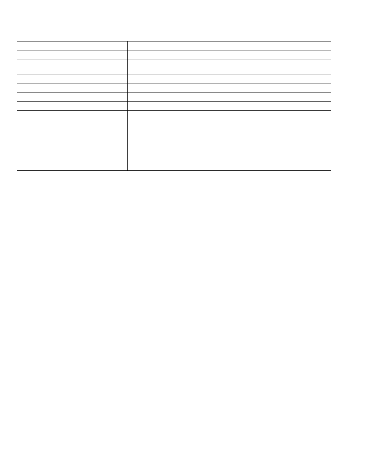
3.1 Removing the almi plate
(See fig.1)
(1) Remove the six screws A, two screws B and one screw C
attaching the almi plate.
(2) Remove the almi plate from main body.
B
A
A
almi plate
C
Fig.1
(No.MA252)1-3
Page 4
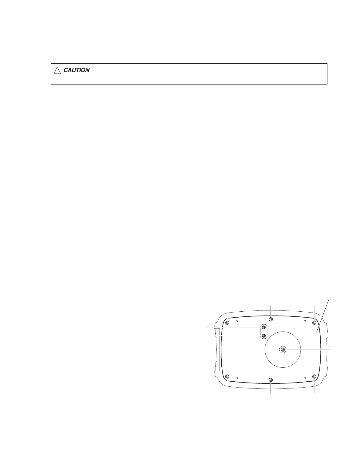
3.2 Removing the main board
(See fig.2 to 4)
• Remove the almi plate.
(1) Remove the five screws D and one screw D' attaching the
main board. (See fig.2)
(2) Remove the one screw E attaching the main board. (See
fig.3)
(3) Take out the main board, and then remove the wire from
speaker terminal. (See fig.4)
Reference:
When attach the screw D', spring and washer are attached
with screw D'. (See fig.2)
Caution:
When reassembly, wire should connect as same as before disassembly. (See fig.4)
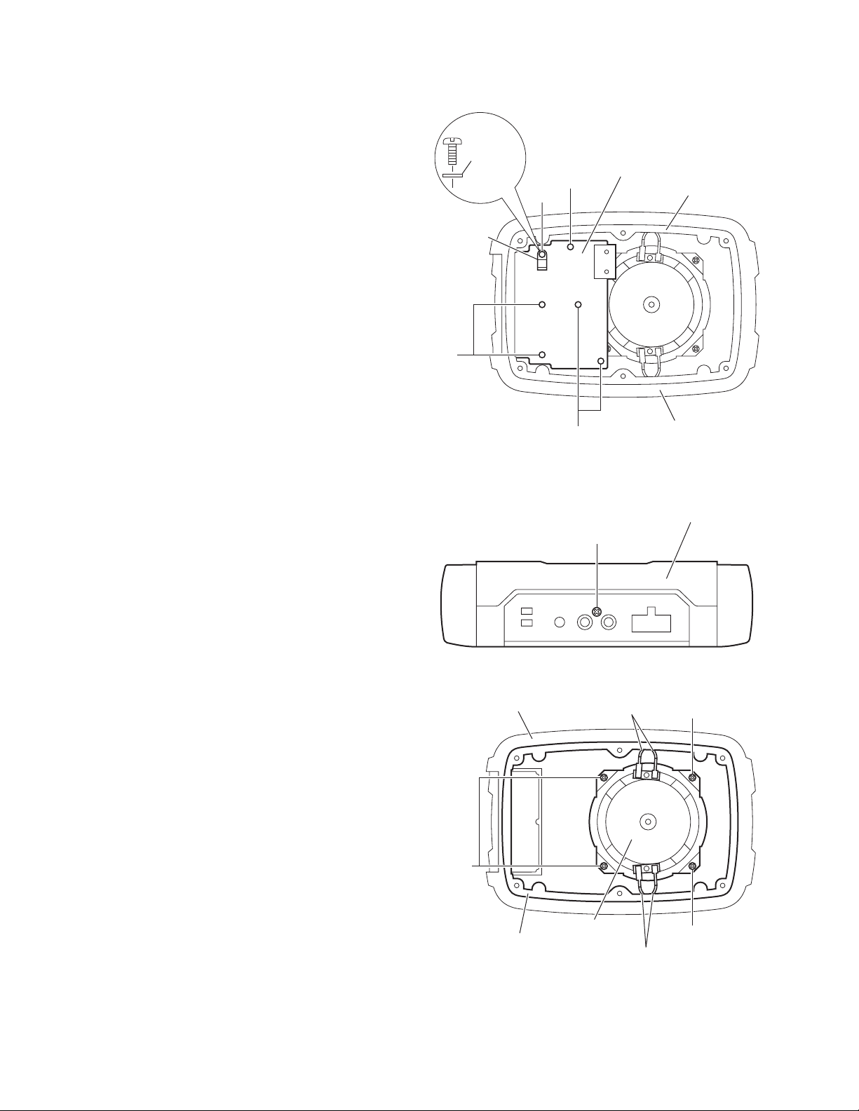
3.3 Removing the speaker
(See fig.4)
• Remove the almi plate.
• Remove the main board.
(1) Remove the base cabinet.
(2) Remove the four screws F attaching the speaker.
(3) Shift up the speaker and take out.
washer
spring
D
D'
main board
D
D
Fig.2
spacer
base cabinet
base cabinet
F
E
Fig.3
wire (white)
upper cabinet
F
1-4 (No.MA252)
spacer
speaker
wire (blue)
Fig.4
F
Page 5
This service manual does not describe ADJUSTMENT.
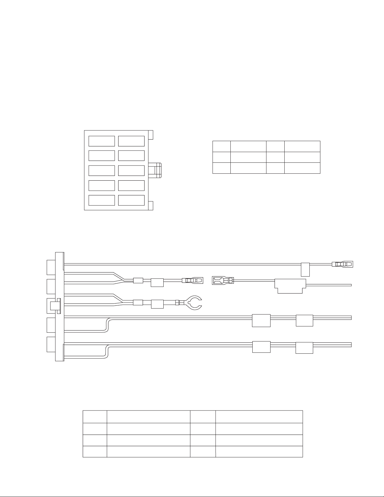
5.1 10 PIN CORD DIAGRAM
SECTION 4
ADJUSTMENT
SECTION 5
TROUBLESHOOTING
1.BL/WH
4.WH/BK
5.GY/BK
1 BL/WH
2 YL
7 YL
3 BK
8 BK
9 WH
4 WH/BK
2.YL
3.BK
6.NC
7.YL
8.BK
9.WH
10.GY
REMOTE
MEMORY
GND
FL+
FL-
POWER
LEAD
GROUND
BK
BL
WH
Black
Blue
White
TO L CHANNEL
SPEAKER OUTPUT
GY
YL
Gray
Yellow
TO ANPLEFIER
OR
RECEIVER
REMOTE OUT
OR
POWER LEAD
10 GY
5 GY/BK
RR
FR
FL
RL
Rear Right
Front Right
Front Left
Rear Left
FR+
FR-
REMOTE
GND
MEMORY
TO R CHANNEL
SPEAKER OUTPUT
Remote Out
Ground
Memory Backup Battery+
TO ANPLEFIER
OR
RECEIVER
(No.MA252)1-5
Page 6

Victor Company of Japan, Limited
Mobile Entertainment Business Group Mobile Entertainment Category 10-1,1chome,Ohwatari-machi,Maebashi-city,Gumma-ken, 371-8543,Japan
(No.MA252)
Printed in Japan
VPT
Page 7
PARTS LIST
CS-BB2J,CS-BB2U
* All printed circuit boards and its assemblies are not available as service parts.
MA252
- Contents -
Exploded view of general assembly and parts list (Block No.M1)
Electrical parts list (Block No.01)
Packing materials and accessories parts list (Block No.M3)
3-2
3-4
3-6
3-1
Page 8

Exploded view of general assembly and parts list
27
Block No.
M
M
1
M
27
27
13
25
26
26
12
4
1
A
B
6
20
16
A
7
15
25
25
16
14
3
8
11
29
24
21
22
28
23
30
24
24
31
32
9
34
9
33
17
19
18
17
2
B
17
10
35
5
Main board
3-2
Page 9

General Assembly
Symbol No. Part No. Part Name Description Local
1 LV10905-003A BASE CABINET
2 LV34988-001A SPACER
3 LV10906-002A UPPER CABINET
4 LV43784-002A INPUT LABEL
5 LV43801-001A SPACER (x2)
6 LV43801-003A SPACER
7 LV43801-002A SPACER
8 LE10014-019A SPEAKER
9 QYSBSF4010ZA TAP SCREW M4 x 10mm(x4)
10 WJJ0473-001A-E E-SI C WIRE C-C
11 LV43938-001A CUSHION (x2)
12 LV10907-002A UPPER COVER
13 LV34921-004A GRILL ASSY
14 LV43801-004A SPACER (x2)
15 LV43801-005A SPACER (x2)
16 LV43801-001A SPACER (x2)
17 QYSDSF3016ZA TAP SCREW M3 x 16mm(x8)
18 LV43955-001A WASHER
19 GN40028-001A LEAF SPRING
20 QYSDSF3008MA TAP SCREW M3 x 8mm
21 LV34922-001A ALMI PLATE
22 LV34923-002A SPACER
23 LV43803-001A SPACER (x2)
24 QYSDSF4045NA TAP SCREW M4 x 45mm(x6)
25 LV43785-001A SPECIAL SCREW (x4)
26 GN30007-016A SPACER (x4)
27 LV43785-001A SPECIAL SCREW (x4)
28 QYSDSP4008MA SCREW M4 x 8mm
29 QYSDSP3008MA SCREW M3 x 8mm(x2)
30 LV37031-001A NAME PLATE
31 QYSDSF3010MA TAP SCREW M3 x 10mm(x2)
32 GN40036-001A IC BRACKET
33 LV34929-001A SUB HEATSINK
34 QYSDSP3012ZA SCREW M3 x 12mm(x2)
35 LV34991-001A SW BLACKET
Block No. [M][1][M][M]
3-3
Page 10

Electrical parts list
Main board
Block No. [0][1]
Symbol No.
IC101 NJM4580L IC
IC301 NJM2777D IC
IC311 NJM4580L IC
IC321 NJM4580L IC
IC331 NJM4580L IC
IC511 NJM78M08FA IC
IC701 TDA8560Q IC
Q511 2SB1322/RS/-T TRANSISTOR
Q512 DTC144ESA-T DIGI TRANSISTOR
Q601 DTA144ESA-T DIGI TRANSISTOR
Q602 DTC144ESA-T DIGI TRANSISTOR
Q603 DTC144ESA-T DIGI TRANSISTOR
Q604 DTA144ESA-T DIGI TRANSISTOR
Q701 2SD1302/ST/-T TR.IM
D301 MTZJ10A-T2 Z DIODE
D302 MTZJ4.7A-T2 Z DIODE
D501 1N5401-F64 DIODE
D511 1SS133-T2 SI DIODE I/M
D512 1SS133-T2 SI DIODE I/M
D513 MTZJ10A-T2 Z DIODE
D601 1SR139-400-T2 SI DIODE
D602 MTZJ3.6A-T2 ZENER DIODE IM
D603 1SS133-T2 SI DIODE I/M
D604 1SS133-T2 SI DIODE I/M
D801 SLR-342MC-T LED
D802 SLR-342MC-T LED
C101 QEKJ1EM-106Z E CAPACITOR 10uF 25V M
C102 QEKJ1EM-106Z E CAPACITOR 10uF 25V M
C103 QCFB1HZ-104Y C CAPACITOR 0.1uF 50V Z
C104 QCFB1HZ-104Y C CAPACITOR 0.1uF 50V Z
C105 QDYB1CM-103Y C CAPACITOR 0.01uF 16V M
C106 QEKJ1HM-474Z E CAPACITOR 0.47uF 50V M
C107 QEKJ1HM-474Z E CAPACITOR 0.47uF 50V M
C201 QEKJ1EM-106Z E CAPACITOR 10uF 25V M
C202 QEKJ1EM-106Z E CAPACITOR 10uF 25V M
C203 QCFB1HZ-104Y C CAPACITOR 0.1uF 50V Z
C204 QCFB1HZ-104Y C CAPACITOR 0.1uF 50V Z
C205 QDYB1CM-103Y C CAPACITOR 0.01uF 16V M
C206 QEKJ1HM-474Z E CAPACITOR 0.47uF 50V M
C207 QEKJ1HM-474Z E CAPACITOR 0.47uF 50V M
C210 QEKJ1CM-476Z E CAPACITOR 47uF 16V M
C301 QEKJ1EM-106Z E CAPACITOR 10uF 25V M
C302 QEKJ1CM-226Z E CAPACITOR 22uF 16V M
C303 QEKJ1EM-106Z E CAPACITOR 10uF 25V M
C304 QEKJ1EM-106Z E CAPACITOR 10uF 25V M
C310 QEKJ1CM-476Z E CAPACITOR 47uF 16V M
C311 QEKJ1HM-105Z E CAPACITOR 1uF 50V M
C312 QEKJ1HM-475Z E CAPACITOR 4.7uF 50V M
C313 QEKJ1HM-475Z E CAPACITOR 4.7uF 50V M
C314 QEKJ1HM-475Z E CAPACITOR 4.7uF 50V M
C320 QEKJ1CM-476Z E CAPACITOR 47uF 16V M
C321 QFV61HJ-104Z MF CAPACITOR 0.1uF 50V J
C322 QFV61HJ-104Z MF CAPACITOR 0.1uF 50V J
C323 QFV61HJ-104Z MF CAPACITOR 0.1uF 50V J
C324 QFV61HJ-104Z MF CAPACITOR 0.1uF 50V J
C330 QEKJ1CM-476Z E CAPACITOR 47uF 16V M
C331 QFV61HJ-473Z MF CAPACITOR 0.047uF 50V J
C332 QFV61HJ-563Z MF CAPACITOR 0.056uF 50V J
C333 QFV61HJ-183Z MF CAPACITOR 0.018uF 50V J
C334 QFV61HJ-124Z MF CAPACITOR 0.12uF 50V J
C340 QEKJ1CM-476Z E CAPACITOR 47uF 16V M
C501 QETM1CM-338 E CAPACITOR 3300uF 16V M
C502 QDX31EM-104Z C CAPACITOR 0.1uF 25V M
C503 QFV61HJ-104Z MF CAPACITOR 0.1uF 50V J
C504 QFV61HJ-103Z MF CAPACITOR 0.01uF 50V J
C511 QEKJ1CM-107Z E CAPACITOR 100uF 16V M
C512 QDX31EM-104Z C CAPACITOR 0.1uF 25V M
C513 QDX31EM-104Z C CAPACITOR 0.1uF 25V M
C514 QEKJ1CM-107Z E CAPACITOR 100uF 16V M
Part No. Part Name Description Local
Symbol No.
C521 QEKJ1CM-107Z E CAPACITOR 100uF 16V M
C601 QEKJ1AM-227Z E CAPACITOR 220uF 10V M
C602 QEKJ1HM-105Z E CAPACITOR 1uF 50V M
C603 QEKJ1HM-105Z E CAPACITOR 1uF 50V M
C604 QETM1EM-108 E CAPACITOR 1000uF 25V M
C605 QEKJ1EM-106Z E CAPACITOR 10uF 25V M
C701 QDX31EM-473Z C CAPACITOR 0.047uF 25V M
C702 QEKJ1HM-475Z E CAPACITOR 4.7uF 50V M
C703 QFV61HJ-334Z MF CAPACITOR 0.33uF 50V J
C704 QFV61HJ-334Z MF CAPACITOR 0.33uF 50V J
R101 QRE141J-102Y C RESISTOR 1kΩ 1/4W J
R102 QRE141J-102Y C RESISTOR 1kΩ 1/4W J
R103 QRE141J-102Y C RESISTOR 1kΩ 1/4W J
R104 QRE141J-474Y C RESISTOR 470kΩ 1/4W J
R105 QRE141J-104Y C RESISTOR 100kΩ 1/4W J
R106 QRE141J-102Y C RESISTOR 1kΩ 1/4W J
R107 QRE141J-222Y C RESISTOR 2.2kΩ 1/4W J
R108 QRE141J-102Y C RESISTOR 1kΩ 1/4W J
R109 QRE141J-273Y C RESISTOR 27k
R110 QRE141J-104Y C RESISTOR 100k
R111 QRE141J-104Y C RESISTOR 100kΩ 1/4W J
R112 QRE141J-224Y C RESISTOR 220kΩ 1/4W J
R113 QRE141J-224Y C RESISTOR 220kΩ 1/4W J
R114 QRE141J-102Y C RESISTOR 1kΩ 1/4W J
R201 QRE141J-102Y C RESISTOR 1kΩ 1/4W J
R202 QRE141J-102Y C RESISTOR 1kΩ 1/4W J
R203 QRE141J-102Y C RESISTOR 1kΩ 1/4W J
R204 QRE141J-474Y C RESISTOR 470kΩ 1/4W J
R205 QRE141J-104Y C RESISTOR 100kΩ 1/4W J
R206 QRE141J-102Y C RESISTOR 1kΩ 1/4W J
R207 QRE141J-222Y C RESISTOR 2.2kΩ 1/4W J
R208 QRE141J-102Y C RESISTOR 1kΩ 1/4W J
R209 QRE141J-273Y C RESISTOR 27kΩ 1/4W J
R210 QRE141J-104Y C RESISTOR 100kΩ 1/4W J
R211 QRE141J-104Y C RESISTOR 100kΩ 1/4W J
R212 QRE141J-224Y C RESISTOR 220kΩ 1/4W J
R213 QRE141J-224Y C RESISTOR 220kΩ 1/4W J
R214 QRE141J-102Y C RESISTOR 1kΩ 1/4W J
R302 QRE141J-104Y C RESISTOR 100kΩ 1/4W J
R304 QRE141J-473Y C RESISTOR 47kΩ 1/4W J
R305 QRE141J-102Y C RESISTOR 1kΩ 1/4W J
R306 QRE141J-203Y C RESISTOR 20kΩ 1/4W J
R311 QRE141J-104Y C RESISTOR 100kΩ 1/4W J
R312 QRE141J-223Y C RESISTOR 22kΩ 1/4W J
R313 QRE141J-223Y C RESISTOR 22kΩ 1/4W J
R314 QRE141J-223Y C RESISTOR 22k
R315 QRE141J-104Y C RESISTOR 100k
R316 QRE141J-223Y C RESISTOR 22k
R317 QRE141J-104Y C RESISTOR 100kΩ 1/4W J
R318 QRE141J-104Y C RESISTOR 100k
R319 QRE141J-104Y C RESISTOR 100k
R321 QRE141J-433Y C RESISTOR 43kΩ 1/4W J
R322 QRE141J-363Y C RESISTOR 36k
R323 QRE141J-104Y C RESISTOR 100kΩ 1/4W J
R324 QRE141J-153Y C RESISTOR 15k
R331 QRE141J-682Y C RESISTOR 6.8k
R332 QRE141J-682Y C RESISTOR 6.8kΩ 1/4W J
R333 QRE141J-303Y C RESISTOR 30k
R334 QRE141J-303Y C RESISTOR 30k
R336 QRE141J-102Y C RESISTOR 1kΩ 1/4W J
R511 QRE141J-103Y C RESISTOR 10k
R512 QRE141J-472Y C RESISTOR 4.7k
R521 QRE141J-472Y C RESISTOR 4.7kΩ 1/4W J
R522 QRE141J-562Y C RESISTOR 5.6k
R601 QRE141J-102Y C RESISTOR 1k
R602 QRE141J-473Y C RESISTOR 47k
R603 QRE141J-101Y C RESISTOR 100
R604 QRE141J-102Y C RESISTOR 1kΩ 1/4W J
R605 QRE141J-154Y C RESISTOR 150k
R606 QRE141J-473Y C RESISTOR 47k
R607 QRE141J-472Y C RESISTOR 4.7kΩ 1/4W J
R701 QRE141J-103Y C RESISTOR 10k
R702 QRE141J-222Y C RESISTOR 2.2k
R703 QRE141J-152Y C RESISTOR 1.5kΩ 1/4W J
R801 QRE141J-392Y C RESISTOR 3.9k
Part No. Part Name Description Local
Ω
1/4W J
Ω
1/4W J
Ω
1/4W J
Ω
1/4W J
Ω
1/4W J
Ω
1/4W J
Ω
1/4W J
Ω
1/4W J
Ω
1/4W J
Ω
1/4W J
Ω
1/4W J
Ω
1/4W J
Ω
1/4W J
Ω
1/4W J
Ω
1/4W J
Ω
1/4W J
Ω
1/4W J
Ω
1/4W J
Ω
1/4W J
Ω
1/4W J
Ω
1/4W J
Ω
1/4W J
Ω
1/4W J
3-4
Page 11

Symbol No.
R802 QRE141J-104Y C RESISTOR 100kΩ 1/4W J
VR801 QVQ0294-Z24 V RESISTOR
L501 QQR0703-001 CHOKE COIL
CJ101 QNN0068-001 JACK ASSY
CJ301 QNS0240-001 3.5 JACK
CN101 QGA4201F2-10 CONNECTOR W-B (1-10)
CN301 QGB2022K1-06 CONNECTOR B-B (1-6)
CN401 QGB2022K2-06 CONNECTOR B-B (1-6)
CN701 QGA3901C1-04 CONNECTOR W-B (1-4)
CN801 QGA2001C1-03 CONNECTOR W-B (1-3)
S401 QSW0991-001 SLIDE SWITCH
S402 QSW0991-001 SLIDE SWITCH
S801 QSW0799-001 PUSH SW
Part No. Part Name Description Local
3-5
Page 12

Packing materials and accessories parts list
No additional / supplemental order of WARRANTY CARDs are available.
A5
A6,A7,A8
A4
A12
CS-BB2J
P6
A1,A2,
A13,A14,A15
CS-BB2U
P7
P5
Block No.
P9
A9
M
3
A10
P2
M
P8
A11
M
P6
A1,A2,A3
P4
P3
3-6
P1
Page 13

Packing and Accessories
Symbol No. Part No. Part Name Description Local
A 1 LVT1544-001A INST BOOK ENG
A 2 LVT1544-002A INST BOOK SPA FRE BB2J
A 2 LVT1544-003A INST BOOK CHI(TAIWAN) TAI BB2U
A 3 LVT1544-004A INST BOOK ARA PER BB2U
A 4 RM-RK80C REMOTE CONTROLLER
A 5 QAM0650-002 CAR CABLE
A 6 GN40033-001A MAGIC TAPE (x4)
A 7 LV41413-001A DOUBLE FACE
A 8 QZW0004-001 WIRE CLAMP
A 9 QYSDSA4016MA TAP SCREW M4 x 16mm(x4)
A 10 QYSSSA4020MA TAP SCREW M4 x 20mm(x4)
A 11 LV43826-001A STAY (x4)
A 12 LV41298-002A CAUTION LABEL
A 13 ------------ WARRANTY CARD BT-51018-4 BB2J
A 14 BT-51034-2 J=REGIST CARD BB2J
A 15 ------------ WARRANTY CARD BT-52006-2 BB2J
P 1 LV36780-002A CARTON
P 2 LV21719-001A CUSHION(L)
P 3 LV21720-001A CUSHION(U)
P 4 QPC04003515P POLY BAG 40cm x 35cm
P 5 QPA01503505 POLY BAG 15cm x 35cm
P 6 QPC02503515P POLY BAG 25cm x 35cm
P 7 QPA00701005 POLY BAG 7cm x 10cm
P 8 QPA00701005 POLY BAG 7cm x 10cm
P 9 QPA00701005 POLY BAG 7cm x 10cm
Block No. [M][3][M][M]
3-7
Page 14

SCHEMATIC DIAGRAMS
ACTIVE SUBWOOFER SYSTEM
CS-BB2J,CS-BB2U
CD-ROM No.SML200603
Lead free solder used in the board (material : Sn-Ag-Cu, melting point : 219 Centigrade)
Contents
Block diagram
Standard schematic diagrams
Printed circuit boards
COPYRIGHT 2006 Victor Company of Japan, Limited.
2-2
2-3
2-5 to 6
No.MA252SCH
2006/3
Page 15

Safety precaution
!
Burrs formed during molding may be left over on some parts of the chassis. Therefore,
pay attention to such burrs in the case of preforming repair of this system.
2-1
Page 16

Block diagram
VR801
LEVEL
LINE IN
CJ101
IC101
-1
INPUT
AMP.
IC101
-2
S801
BOOST SW
CN801
CJ301
IC301
E.VOL
(V.C.A)
+8V
PHASE SW
S402
PHASE
IC311
-1
PHASE
SELECT
IC311
-2
L.P.F. SW
S401
CN401
CN301
IC321
IC331
-1
H.P.F L.P.F
IC331
-2
Q604
Q701
MUTE
IC701
POWER
AMP.
SPEAKER
CN701
CN101
BATTERY
SPEAKER
(CAR CABLE)
IC511
8VREG.
Q601 to Q603
STAND BY
2-2
Page 17

T
S
N
N
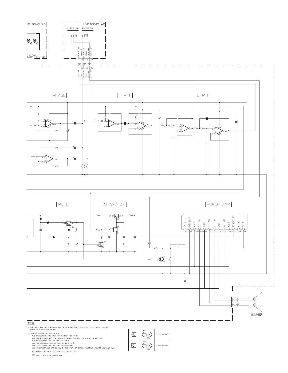
Standard schematic diagram
C106
0.47/50
R110
100k
27k
R111
100k
C107
0.47/50
C206
0.47/50
R210
100k
27k
R211
100k
C207
0.47/50
CJ101
QNN0068-001
C105C205
R109
1k1k
0.010.01
R108R208
R209
R212 R112
R113
220k
220k 220k
R213
220k
IC101( 1/2)
NJM4580L
IC101( 1/2)
NJM4580L
R114
R214
VR801
QVQ0294-Z24
100k
R802
S801
QSW0799-001
CN801
QGA2001C1-03
C304
10/16
IC301
NJM2777D
C210
1k
1k
47/16
C301
R304 R336
10/16
47k 1k
C310
47/16
R302
100k
D301
D302
C303
10/16
MTZJ10A-T2
MTZJ4.7A-T2
C302
22/16
20k
R306
C311
1/50
SLR-342MC-T
CJ301
QNS0240-001
1k
R305
R801
3.9k
D802D801
SLR-342MC-T
R312
22k
R315
100k
R311
100k
I
I
100k
2.2k
R105
R107
470k
1k
R104
R106
C104
C204
0.1
0.1
R103
R203
1k
1k
C203
C103
0.1
0.1
R101 R102 R202 R201
1k 1k 1k 1k
C101
C102
10/16
CN101
QAM0477-001
!
QGA4201F2-10
10/16
C201
R204 R205
2.2k
R207
1k
470k 100k
R206
C521
100/10
D601
MTZJ3.6A-
1SR139-400-T2
C604
1000/25
D602
1
10/16
C202
10/16
C504
C511
100/16
C512
IC511
NJM78M08FA
0.1
C513
0.1
D513
C514
100/10
MTZJ10A-T2
R522 R521
5.6k 4.7k
Q511
2SB1322/RS/-T
D511
1SS133-T2
10k
R511
4.7k
DTC144ESA-T
R512
Q512
0.01
L501
QQR0703-001
0.1
C501
C503
3300/16
D501
C502
1N5401-F64
D512
1SS133-T2
0.1
2-3
Parts are safety assurance parts.
When replacing those parts make
sure to use the specified one.
Page 18
R801
D802D801
-342MC-T
SLR-342MC-T
J301
NS0240-001
S402
S401
QSW0991-001
3.9k
QSW0991-001
CN401
QGB2022J1-06
CN301
QGB2022K1-06
100/10
R312
R315
100k
22k
100k
R311
D601
1SR139-400-T2
C604
D602
MTZJ3.6A-T2
1000/25
IC311( 1/2)
NJM4580L
R313
R314
IC311( 1/2)
NJM4580L
R316
D603
1SS133-T2
22k
22k
22k
C320
Q604
DTA144ESA-T
D604
R606
C312
4.7/25
47/16
C313
4.7/25
C314
4.7/25
1SS133-T2
47k
C605
R607
4.7k
10/16
100k
100k
100k
R317
R318
R319
DTC144ESA-T
C321 C322
0.1 0.1
R601
1k
R602
47k
Q603
R321
IC321( 1/2)
NJM4580L
DTC144ESA-T
100
R603
R322
36k
43k
DTA144ESA-T
Q602
C601
220/10
Q601
C323 C324
0.1 0.1
C602
1/50
1k
R604
IC321( 1/2)
NJM4580L
R605
150k
C603
R323
R324
100k
1/50
15k
C702
R701
10k
2SD1302/ST/-T
4.7/25
R702
R333
C334
0.12
R334
30k
30k
IC331( 1/2)
0.018
NJM4580L
C333
C340
47/16
47/16
R332
6.8k
R703
C331
1.5k
C703
C704
C332
0.056
IC331( 1/2)
0.047
NJM4580L
0.33
0.33
IC701
TDA8560Q
C330
R331
6.8k
2.2k
Q701
C701
0.047
CN701
WJJ0473-001AQGA3901C1-04
2-4
Page 19

Printed circuit board
Q604
R305
Main board
Lead free solder used in the board (material : Sn-Ag-Cu, melting point : 219 Centigrade)
C702
R702
R605
Q601
R701
D602
(Main board)
C704
L501
C501
C502
IC701
R104
R106
C103
R102
C104
R103
C701
R105
R107
C105
R109
R108
CN701
C106 C107
C206
C207
R703
C703
R110
R212
R210
R211
R213
R113
R111
R112
Q701
C603
R601
D601
C210
C303
IC101
D512
R114
R214
Q512
D301
R336
C604
R512
C301
D302
D511
R304
R511
IC301
2-5
D501
C504
C503
CN101
R101
C101
C102
R204
C201C202
R206
CJ101
C204
R203
C203
R202
R201
R209
R208
C205
R207
R205
C304
R306
Page 20

6
05
Q601
R701
D602
Q604
D604
D603
R606
Q603
R607
R603
Q602
R602
R604
C601
03
601
601
D512
Q512
C604
R512
D511
R511
Q511
C512
C511
C605
C514
D513
C602
R521
R522
C513
C521
C340
C334
R334
R333
R332
C332
R331
IC331
C333
C331
(Connevtor board)
S401
S402
CN401
IC511
C210
C303
R304
C310
R313
C320
R312
R311
C330
R323
R321
C324
R324
CN801
C323
R114
C301
D301
C302
R315
R316
C322
R214
R336
D302
IC301
C304
R306
C314
R305
CJ301
C312
R317
R318
R319
R302
C311
IC311
R314
C313
CN301
C321
R322
IC321
D801
S801
R802
VR801
(Volume board)
D802
R801
2-6
Page 21

Victor Company of Japan, Limited
Mobile Entertainment Business Group Mobile Entertainment Category 10-1,1chome,Ohwatari-machi,Maebashi-city,Gumma-ken,371-8543,Japan
(No.MA252SCH)
Printed in Japan
VPT
 Loading...