

Page 1
USER'S
GUIDE
HJT Model 100 Projector
Hughes-JVC Technology Corporation
2310 Camino Vida Roble, Carlsbad, CA 92009-1504 USA
☎
760-929-5300
760-929-5410 e-✉ service@hjt.com
AX
F
Page 2

DECLARATION OF CONFORMITY
PER ISO/IEC GUIDE 22 AND EN 45014
Manufacturer
Hughes-JVC declares that this product conforms to the following
Product Specifications (Directive/Standard):
Safety:
EMC:
In addition, the above product complies with the requirements of
the Low Voltage Directive 73/23 EEC and the EMC Directive 89/336/EEC.
: Hughes JVC Technology Corporation
2310 Camino Vida Roble
Carlsbad, Ca 92009-1504
USA
EN 60950
IEC 950 (1992)
EN 55022 (1988) / CISPR-22 (1986) Class "A"
EN 50082-1 (1992) / IEC 801-2(1991)
EN 50082-1 (1992) / IEC 801-3(1984)
EN 50082-1 (1992) / IEC 801-4(1988)
ANSI C63.4-1992, FCC, Part 15, Class A
105826 First Edition December 1997
Confidential and proprietary information.
© Copyright 1997 by Hughes-JVC Technology Corporation.
All worldwide rights reserved.
This manual was produced by Hughes-JVC Technology Corporation and may be
revised without prior notice.
No part of this manual may be reproduced in any form without the express written
permission of Hughes-JVC Technology Corporation.
®
ILA
is a registered trademark of Hughes-JVC Technology Corporation.
ii
Hughes-JVC Technology Corporation
Page 3

Table of Contents
Safety Information
0.1. Warnings and Cautions .....................................................................................vii
0.2. Installation Safeguards......................................................................................vii
0.3. Heat Safeguards................................................................................................viii
0.3.1. Fans and Ventilation................................................................................. viii
0.4. Light Safeguards ...............................................................................................viii
0.5. Electrical Safeguards.........................................................................................ix
0.5.1. Power Supply............................................................................................ix
Chapter 1. Introduction
1.1. Shipping and Inspection.....................................................................................1-1
1.2. Items Shipped with the HJT Model 100 Projector ..............................................1-1
1.3. Options..............................................................................................................1-2
1.4. Projector Control................................................................................................1-2
1.5. Right and Left Orientation..................................................................................1-2
1.6 Acronyms Used in Manual.................................................................................1-3
Chapter 2. Installation
2.1. Air Flow and Maintenance Clearances...............................................................2-1
2.1.1. Air Flow.....................................................................................................2-1
2.1.2. Maintenance Access.................................................................................2-2
2.2. Physical Dimensions..........................................................................................2-2
2.3. Projector Orientation..........................................................................................2-4
2.4. Projector-to-Screen Distance and Alignment.....................................................2-5
2.5. Lens Throw Distance and Screen Width............................................................2-6
2.6. Power Requirements.........................................................................................2-9
2.7. Signal Sources Connection................................................................................2-9
2.7.1. Terminal or Remote Control......................................................................2-10
2.7.2. Infrared (IR) Windows...............................................................................2-10
2.8. Sources............................................................................................................2-11
2.8.1. Types of Standard Composite Signals......................................................2-11
2.8.2. Red, Green and Blue Analog Signals........................................................2-11
Chapter 3. Operation
3.1. Executive Remote..............................................................................................3-1
3.2. Technician Remote ............................................................................................3-3
3.3. Power ON and OFF...........................................................................................3-6
3.4. Displaying Internal Test Patterns.......................................................................3-6
3.5. Displaying External Signals................................................................................3-7
3.5.1. Internal Source..........................................................................................3-8
3.6. Navigating the Menu..........................................................................................3-8
3.6.1. Displaying the Main Menu.........................................................................3-9
3.6.2. Choosing Numbered Menus......................................................................3-9
3.6.3. To Choose Full or Short Menus................................................................3-9
3.6.4. Menu Selection Examples.........................................................................3-10
3.7. Full Menu Structure ...........................................................................................3-12
3.8. Selecting a Channel...........................................................................................3-12
3.8.1. Active Channel..........................................................................................3-13
HJT Model 100 User’s Guide
iii
Page 4

Table of Contents
3.9. Attaching a Source ............................................................................................3-14
3.10. Picture Settings................................................................................................3-16
3.11. Menu Item Definitions......................................................................................3-17
3.12. Short Menu Structure.......................................................................................3-21
3.13. PC or VT-100 Terminal Control........................................................................3-22
3.13.1. Terminal Preferences..............................................................................3-22
3.13.2. Communications Protocol .......................................................................3-23
Chapter 4. Setup Adjustments
4.1. Setup Preparation..............................................................................................4-2
4.1.1. Projection Lens Focus (Rough).................................................................4-4
4.1.2. Editing Channels, Sources, and VICs .......................................................4-5
4.1.3. Factory-Preset Channels and Sources......................................................4-7
4.1.4. Internal Source..........................................................................................4-8
4.2. Timing Settings and Adjustments ......................................................................4-8
4.2.1. Clamp Type...............................................................................................4-8
4.2.2. VTR Mode.................................................................................................4-8
4.2.3. Blanking....................................................................................................4-9
4.2.4. Phase........................................................................................................4-9
4.3. Geometric Adjustments .....................................................................................4-10
4.3.1. Centering (G)............................................................................................4-10
4.3.2. Size...........................................................................................................4-10
4.3.3. Bow...........................................................................................................4-12
4.3.4. Skew/Rotate (G) .......................................................................................4-13
4.3.5. Linearity (G)..............................................................................................4-14
4.3.6. Edge Linearity...........................................................................................4-16
4.3.7. Keystone...................................................................................................4-17
4.3.8. Pincushion................................................................................................4-18
4.3.9. Centering (Red and Blue) .........................................................................4-19
4.3.10. Linearity (R and B)..................................................................................4-19
4.3.11. Skew/Rotate (R and B)........................................................................... 4-20
4.3.12. Projection Lens Focus (Fine) ..................................................................4-20
4.4. CRT Focus and H/V Dynamic Focus.................................................................4-21
4.5. ILA
4.6. Convergence (XY Registration).........................................................................4-23
4.7. Black Level (G2) and Sensitivity Offset..............................................................4-29
4.8. Uniformity (Shading).......................................................................................... 4-31
4.9. Picture Settings .................................................................................................4-34
®
4.6.1. Purpose of Convergence..........................................................................4-23
4.6.2. Cursor Shapes and Sizes..........................................................................4-23
4.6.3. Convergence Profiled................................................................................4-24
4.7.1. Black Level (G2) .......................................................................................4-29
4.7.2. Sensitivity Offset.......................................................................................4-30
4.7.3. Threshold Offset.......................................................................................4-30
4.8.1. Sensitivity Uniformity.................................................................................4-31
4.8.2. Threshold Uniformity.................................................................................4-32
4.8.3. Color Balance (Grey Scale).......................................................................4-33
4.9.1. Brightness.................................................................................................4-35
4.9.2. Contrast....................................................................................................4-35
4.9.3. Color, Tint, Sharpness..............................................................................4-36
4.9.4. Black Enhance..........................................................................................4-36
4.9.5. VIC Settings..............................................................................................4-36
Sensitivity and Bias....................................................................................4-21
iv
Hughes-JVC Technology Corporation
Page 5

Table of Contents
4.10. Backing up Settings.........................................................................................4-37
4.11. Video Input Cards............................................................................................4-38
4.11.1. Installing (or Removing) a VIC ................................................................4-39
4.11.2. Connecting VIC Source Cables...............................................................4-40
4.11.3. VIC Editing..............................................................................................4-40
4.11.4. VIC Settings............................................................................................ 4-42
4.12. Updating Software...........................................................................................4-44
Chapter 5. Preventive Maintenance
5.1. Preventive Maintenance.....................................................................................5-1
5.1.1. Cleaning the Cabinet.................................................................................5-1
5.1.2. Cleaning the Projector Lens......................................................................5-2
5.1.3. Air Filters...................................................................................................5-2
Chapter 6. System Specifications
Image Quality...........................................................................................................6-1
Input Compatibility....................................................................................................6-1
Inputs........................................................................................................................6-1
Control Ports.............................................................................................................6-1
Operating Parameters ..............................................................................................6-2
Installation................................................................................................................6-2
Accessories (included)..............................................................................................6-2
Accessories (optional) ..............................................................................................6-2
Appendix A.
Extron
Appendix B. Configuration Data Export/Import Procedures
Chapter 7. Glossary Of Terms
Switcher Interface to Model 100
........................................................Glossary-1
..................
.......
Appendix A-1
Appendix B-1
Indexes
Index of Figures..................................................................................................Index-1
Index of Tables...................................................................................................Index-2
Index of Photos...................................................................................................Index-2
HJT Model 100 User's Guide
v
Page 6

Table of Contents
vi
Hughes-JVC Technology Corporation
Page 7
Safety Information
Do not open the projector covers.
projector. Refer pr oblems to authorized service personnel.
Before operating the projector, read this safety section thoroughly.
be performed by HJT qualified service personnel. Recommended safety equipment is
specified in the
This HJT Model 100 Projector complies with the limits for a Class A computing device in
accordance with the specifications in subpart J of Par t 15 of the FCC Rules and
Regulations. The FCC rules are designed t o pr ovide reasonable pr ot ection against such
interference in a commerc ial/ industrial application.
Operating this equipment in a r e sident ial ar ea may cause harmful interference. User will
be required to correct the interference at their expense.
Use shielded interconnect cables with this equipment to insure com pliance with the
pertinent RF emission limits governing this device.
HJT Model 100 Projector Service Manual.
0.1. Warnings and Cautions
Thoroughly read and follow all Warning and Caution statements in this manual.
Warning and Caution definitions are as follows:
There are no user-serviceable parts inside the
Service should
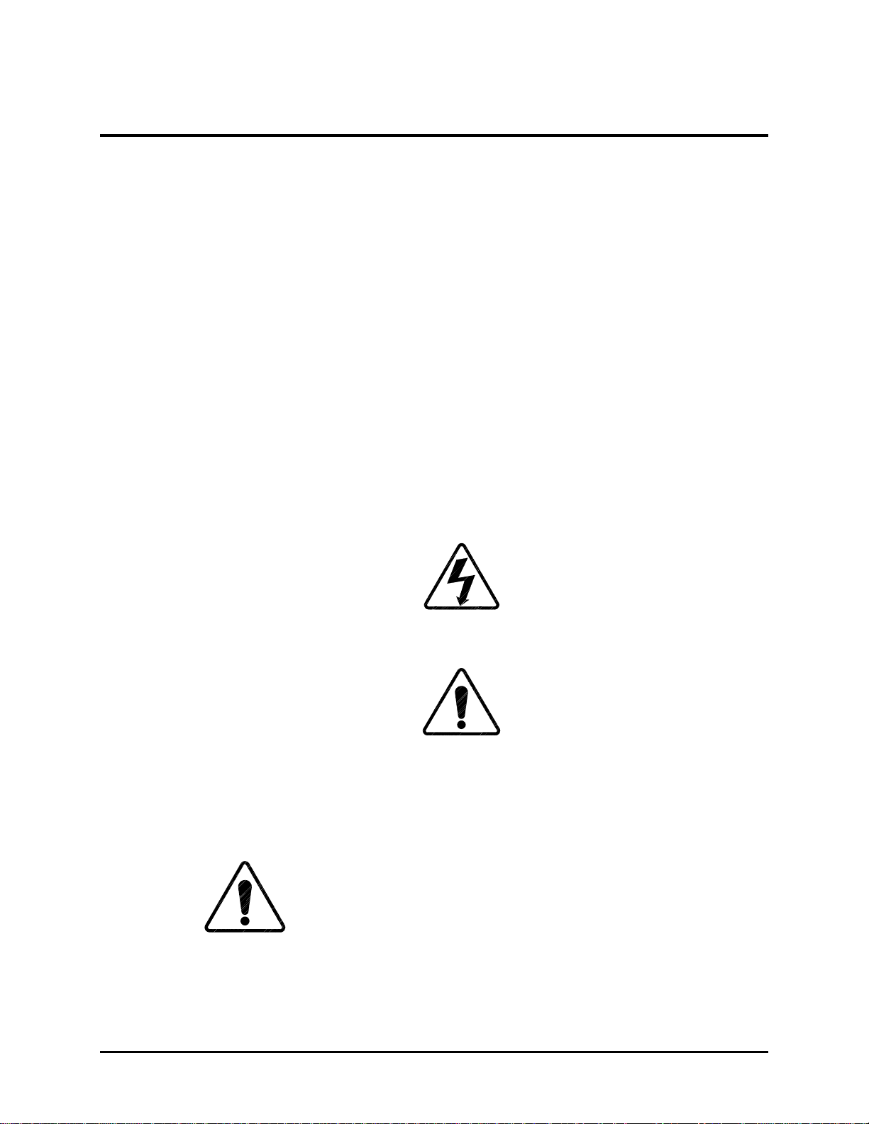
WARNING SYMBOL
electric shock hazard in a procedure or situation t hat could r esult in
personal injury if improperly performed.
CAUTION SYMBOL
safety hazard or potential light hazard from ultraviolet, infrared or bright
light that could cause severe eye injury or a situation that could result in
damage to the equipment if improperly used.
0.2. Installation Safeguards
CAUTION!!!
without using a safe shipping pallet. Lifting the projector without
supporting the weight at the foot locations can cause severe damage to
the projector. Forklifting a projector upside down requires special
brackets and procedures.
Warns user of a potential
Do not use a forklif t to lift the projector
Warns user of a potential
HJT Model 100 User’s Guide
vii
Page 8

Safety Information
If there is any visible damage to the power cable, disconnect power to the
projector until the damaged cable is r eplaced. Install the projector on a smooth,
vibration-resistant level surface, or ceiling mount, in an area free from dust and
moisture. Do not place the equipment near heat-radiating appliances. Smoke and
steam could adversely affect the internal com ponents.
If mounting the projector, use hardware that can handle a minimum of t hr ee (3)
times the projector weight. I n ceiling mounted applications, always use approved
hardware and installation methods.
0.3. Heat Safeguards
0.3.1. Fans and Ventilation
The projector has multiple fans to cool the projector system.
block the intake or outflow of any fans.
system and must be vented to keep the system running. Blocking air
intake or exhaust ports could cause the project or t o overheat . Do not
enclose the unit in a restricted space (ref er t o physical access and
thermal clearance illustration guidelines) .
If a foreig n obj ect falls inside the projector, im m ediat ely unplug t h e
projector and call a Hughes-JVC cert ified technician for object rem oval.
CAUTION!!!
arc lamp fan has stopped running. This fan protects the arc lamp from
overheating.
0.4. Light Safeguards
Do Not Open The Projector Cover.
ultraviolet, and infrared radiation can be hazardous t o per sonnel.
Access must remain restricted to
personnel.
Heat is emitted within the
Do not unplug the power cord until
Dangerous high voltage, bright light,
Hughes-JVC authorized maintenance
Do not
after
the
viii
Do Not
while the projector is on.
Do Not
projection light can cause eye injury.
look into the output of t he Lighted Projection Lens or the side exhaust fan
look directly into the projection lens from
any distrance
Hughes-JVC Technology Company
. Exposure to
Page 9

0.5. Electrical Safeguards
0.5.1. Power Supply
The projector operates from a 90-132VAC, 200-264VAC, 20/10 Amp,
single-phase, 50-60 Hz AC power source.
POWER SOURCE MATCHES THESE REQUIREMENTS BEFORE
OPERATION!
knowledge of current electrical codes in t he count ry of use.
For continued safe and reliable operation, only use cables supplied by the
manufacturer for power and sig nal connect ions.
Safety Information
VERIFY THAT LOCAL
Installation should be performed by an electrician with
HJT Model 100 User’s Guide
ix
Page 10

Safety Information
x
Hughes-JVC Technology Company
Page 11

1.0 Introduction
o
r
n
c
t
n
s
s
n
e
s
n
w
C
e
T
S
u
Contents
Safety Information ...........................................................................................vii
0.1............................................................................................................................Warnings and Cauti
0.2............................................................................................................................Installation Safegua
0.3............................................................................................................................Heat Safeguards
0.3.1....................................................................................................................Fans and Ventilatio
0.4............................................................................................................................Light Safeguards
0.5............................................................................................................................Electrical Safeguard
0.5.1....................................................................................................................Power Supply
1.0......................................................................................................................Introduction
1.1............................................................................................................................Shipping and Inspe
1.2............................................................................................................................Items Shipped with
1.3............................................................................................................................Options 1-4
1.4............................................................................................................................Projector Control
1.5............................................................................................................................Right and Left Orien
2.0......................................................................................................................Installation
2.1............................................................................................................................Air Flow and Mainte
2.1.1....................................................................................................................Air Flow 2-1
2.1.2....................................................................................................................Maintenance Acces
2.2............................................................................................................................Physical Dimension
2.3............................................................................................................................Projector Orientatio
2.4............................................................................................................................Projector-to-Screen
2.5............................................................................................................................Lens Throw Distanc
2.6............................................................................................................................Power Requirement
2.7............................................................................................................................Signal Sources Con
2.7.1....................................................................................................................Terminal or Remote
2.7.2....................................................................................................................Infrared (IR) Windo
2.8............................................................................................................................Sources 2-11
2.8.1....................................................................................................................Types of Standard
2.8.2....................................................................................................................Red, Green and Blu
2.8.2.1. .....................................................................................................Signal Inputs
3.0......................................................................................................................Operation
3.1............................................................................................................................Executive Remote
3.2............................................................................................................................Technician Remote
3.3............................................................................................................................Power ON and OFF
CAUTION!!! Before applying power to the projector thoroughly read
the safety guidelines outlined at the beginning of this operator’s manual..................3-6
3.4............................................................................................................................Displaying Internal
3.5............................................................................................................................Displaying External
3.5.1....................................................................................................................Internal Source
3.6............................................................................................................................Navigating the Men
3.6.1....................................................................................................................Displaying the Main
HJT Model 100 User’s Guide
1-1
Page 12

Chapter 1—Introduction
d
h
m
n
e
u
o
n
e
e
e
S
e
d
)
y
y
3.6.2....................................................................................................................Choosing Numbere
3.6.3....................................................................................................................To Choose Full or S
3.6.4....................................................................................................................Menu Selection Exa
3.7............................................................................................................................Full Menu Structure
3.8............................................................................................................................Selecting a Channel
3.8.1....................................................................................................................Active Channel
3.9............................................................................................................................Attaching a Source
3.10..........................................................................................................................Picture Settings
3.11..........................................................................................................................Menu Item Definitio
3.12..........................................................................................................................Short Menu Structur
3.13..........................................................................................................................PC or VT-100 Termi
3.13.1. Terminal Preferences........................................................................3-22
3.13.2. Communications Protocol..................................................................3-23
4.0......................................................................................................................Setup Adjustm
4.1............................................................................................................................Setup Preparation
4.1.1....................................................................................................................Projection Lens Foc
4.1.2....................................................................................................................Editing Channels, S
4.1.3....................................................................................................................Factory-Preset Cha
4.1.4....................................................................................................................Internal Source
4.2............................................................................................................................Timing Settings and
4.2.1....................................................................................................................Clamp Type 4-9
4.2.2....................................................................................................................VTR Mode 4-9
4.2.3....................................................................................................................Blanking 4-10
4.2.4....................................................................................................................Phase 4-10
4.3............................................................................................................................Geometric Adjustm
4.3.1....................................................................................................................Centering (G)
4.3.2....................................................................................................................Size4-11
4.3.3....................................................................................................................Bow4-13
4.3.4....................................................................................................................Skew/Rotate (G)
4.3.5....................................................................................................................Linearity (G) 4-16
4.3.6....................................................................................................................Edge Linearity
4.3.7....................................................................................................................Keystone 4-18
4.3.8....................................................................................................................Pincushion 4-19
4.3.9....................................................................................................................Centering (Red and
4.3.10. Linearity (Red and Blue)....................................................................4-20
4.3.11. Skew/Rotate (Red and Blue) .............................................................4-21
4.3.12. Projection Lens Focus (Fine).............................................................4-21
4.4............................................................................................................................CRT Focus and H/V
4.5............................................................................................................................ILA
®
Sensitivity and
4.6............................................................................................................................Convergence (XY R
4.6.1....................................................................................................................Purpose of Converg
4.6.2....................................................................................................................Cursor Shapes and
4.6.3....................................................................................................................Convergence Profil
4.7............................................................................................................................Black Level (G2) an
4.7.1....................................................................................................................Black Level (G2)
4.7.2....................................................................................................................Sensitivity Offset
4.7.3....................................................................................................................Threshold Offset
4.8............................................................................................................................Uniformity (Shading
4.8.1....................................................................................................................Sensitivity Uniformit
4.8.2....................................................................................................................Threshold Uniformit
1-2
Hughes-JVC Technology Company
Page 13

Chapter 1—Introduction
y
n
a
e
t
c
4.8.3....................................................................................................................Color Balance (Gre
4.9............................................................................................................................Picture Settings
4.9.1....................................................................................................................Brightness 4-36
4.9.2....................................................................................................................Contrast 4-36
4.9.3....................................................................................................................Color, Tint, Sharpne
4.9.4....................................................................................................................Black Enhance
4.9.5....................................................................................................................VIC Settings4-37
4.10..........................................................................................................................Backing up Settings
4.11..........................................................................................................................Video Input Cards
4.11.1. Installing (or Removing) a VIC...........................................................4-40
4.11.2. Connecting VIC Source Cables.........................................................4-41
4.11.3. VIC Editing........................................................................................4-41
4.11.4. VIC Settings ......................................................................................4-43
4.12..........................................................................................................................Updating Software
5.0......................................................................................................................Preventive Mai
5.1............................................................................................................................Preventive Mainten
5.1.1....................................................................................................................Cleaning the Cabin
5.1.2....................................................................................................................Cleaning the Projec
5.1.3....................................................................................................................Air Filters 5-2
6.0......................................................................................................................System Specifi
7.0......................................................................................................................Glossary Of Ter
8.0......................................................................................................................Indexes1
The HJT Model 100 Projector accepts a variety of inputs and operat es with a wide range
of frame and raster r at es. The projector meets these requirements with sophisticated
computer terminal control, a uniq ue opt ics system , a high-powered projection arc lamp
and the Hughes-JVC unique
The projector is intended to be used f or the projection of video and graphics, as shown
in this manual. It should not be used for pur poses it was not designed for.
®
ILA
(Image Light Amplifier) assembly.
1.1. Shipping and Inspection
The projector is shipped in a standard shipping container which is not reusable.
A reusable container is optional and recommended if t he projector is moved and shipped
often. The containers ar e equipped with tilt and drop indicators to assist in determining if
the projector was handled properly during shipping.
Upon arrival, inspect the container for any abnormal r eadings, dents, gouges and any
other evidence of rough handling. I m mediately report any abnormal readings or
conditions to the shipping company.
After removing the projector from the shipping container, inspect the projector’s exterior
for signs of shipping dam age like scratches, abrasions, cracks on paint , or other
surfaces. Report any damage to your shipping company immediately.
1.2. Items Shipped with the HJT Model 100 Projector
The following items are shipped with every HJT Model 100 Projector:
1
!
HJT Model 100 User’s Guide.
HJT Model 100 User’s Guide
1-3
Page 14

Chapter 1—Introduction
1.3. Options
The following options are available for HJT Model 100 Project or when ordered through
Hughes-JVC:
1 Projection Lens—Zoom or fixed lens, depending on how ordered.
!
1 Projector Data Backup Disk—Contains backup factory setup data
!
(
see Section 4.1.3, Factory-Preset Channels and Sour ces
NOTE:
Store disk in a safe place f or use if the data needs
).
to be restored.
1 Infrared (IR) Rem ot e Control—Can be used either as an IR remote or
!
connected to the projector as a tethered r em ote.
!
HJT Model 100 Projector Service Manual
Reusable Shipping Container.
!
Optional Video Input Cards:
!
Wide Bandwidth RGBHV.
!
Graphics Enhancer RGBHV.
!
Quad RGBHV Video Mux (multi-port).
!
Component HDTV (YPbPr) Input Module.
!
Quad Standard Decoder Module (with Line Doubler).
!
Projection Lenses:
!
Motorized Zoom 3.1-8.1 lens.
!
Fixed 1:1 Wide Angle lens—Used for short projection distances
!
.
and rear projection applications.
Fixed 1.5:1 lens with offset—Needed for ceiling mounted applications
!
or where wider projection angles are necessary.
Tethered Technician LCD Remote—Works like the remote shipped with the
!
projector but has the addition of a four (4) line display.
Tether Cables from 7.62 t o 30.48 meters (25 to 100 feet).
!
Switcher.
!
Extron System 8.
!
Extron System 10.
!
Extron Lancia.
!
JVC Switchers.
!
External Scan Converter/Line Doubler or Quadrupler.
!
HJT-Faroudja LD200/200U.
!
HJT-Faroudja VP250.
!
HJT-Faroudja VP400A/400A-U.
!
1.4. Projector Control
Use the included Remote Control, or a PC ter m inal t o control the projector.
1-4
Hughes-JVC Technology Company
Page 15
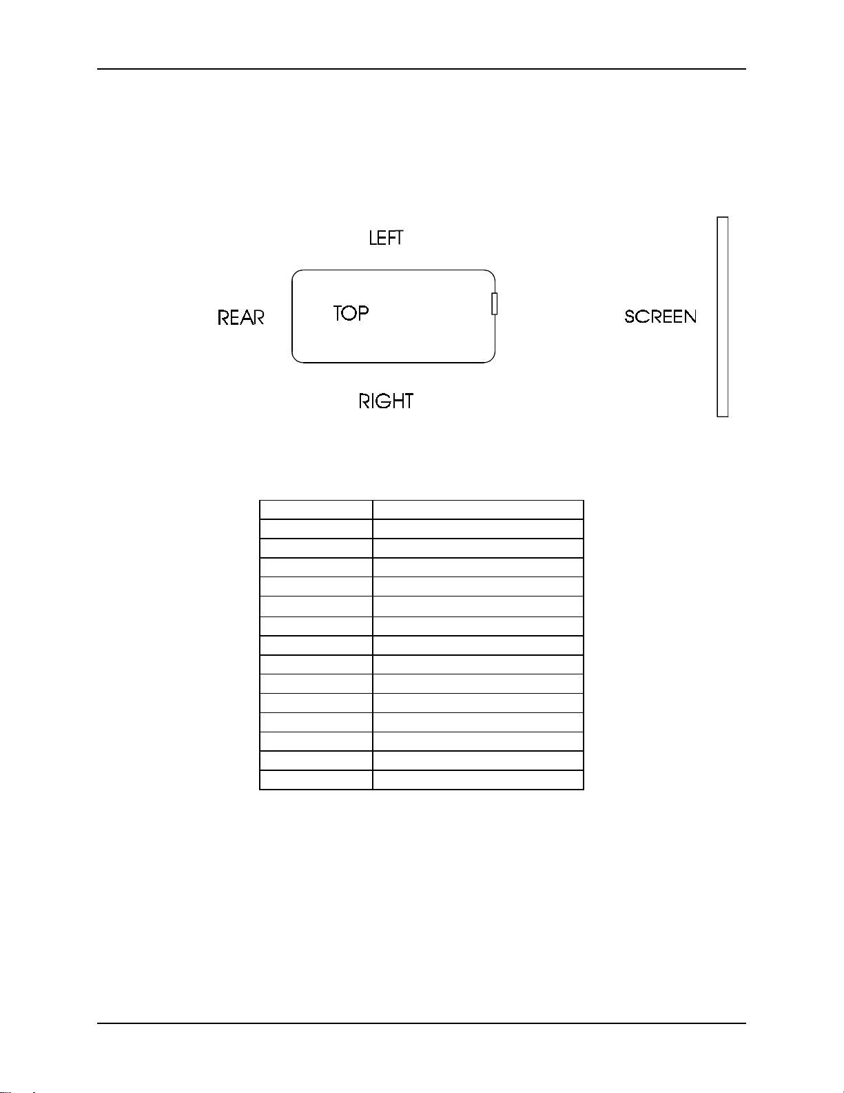
1.5. Right and Left Orientation
References to the right and left side of the projector ar e with the operator
standing behind the projector as the projector is directed at the screen
(
refer to Figure 1.0-1 on page 1-5
Figure 1.0-1
Top View; Left/Right Designation
Chapter 1—Introduction
).
Table 1.0-1
Acronym Explanation
CH
CRT
HDTV
HVPS
ILA
IR
LVPS
PCB
PC
RGB
UV
VIC
VNR
VTR
Acronyms Used In Manual
Channel
Cathode Ray Tube
High Definition Television
®
High Voltage Power Supply
Image Light Amplifier
Infrared
Low Voltage Power Supply
Printed Circuit Board
Personal Computer
Red, Green, Blue
Ultraviolet
Video Input Card
Video Noise Reduction
Video Tape Recorder
HJT Model 100 User’s Guide
1-5
Page 16

Chapter 1—Introduction
1-6
Hughes-JVC Technology Company
Page 17
2.0 Installation
Contents
2.1. Air Flow and Maintenance Clearances...............................................................2-1
2.1.1. Air Flow.....................................................................................................2-1
2.1.2. Maintenance Access.................................................................................2-2
2.2. Physical Dimensions..........................................................................................2-2
2.3. Projector Orientation..........................................................................................2-4
2.4. Projector-to-Screen Distance and Alignment.....................................................2-5
2.5. Lens Throw Distance and Screen Width............................................................2-6
2.6. Power Requirements.........................................................................................2-9
2.7. Signal Sources Connection................................................................................2-9
2.7.1. Terminal or Remote Control......................................................................2-10
2.7.2. Infrared (IR) Windows...............................................................................2-10
2.8. Sources.............................................................................................................2-11
2.8.1. Types of Standard Composite Signals......................................................2-11
2.8.2. Red, Green and Blue Analog Signals........................................................2-11
2.8.2.1 Signal Inputs.................................................................................2-11
2.1. Air Flow and Maintenance Clearances
The HJT Model 100 Projector should be placed in a location where it is easily accessible
on both right and left sides. The area should be well ventilated, and the projector air
intakes and exhausts should not be blocked in any way.
2.1.1. Air Flow
The HJT Model 100 Projector dissipates 4,100 BTUs/ hr and m ust not be placed in an
enclosure that would limit air flow. Adequate ventilation is necessar y to pr ovide proper air
flow to prevent overheating. For optimum oper ation, maintain the following air flow
clearances around the projector f or pr oper heat venting.
The HJT Model 100 Projector should be placed in a location where it is easily accessible
on both sides. The area should be well ventilated and the air intakes and exhausts
should not be blocked in any way. For best operation, refer to
Table 2.0-1 for the recom m ended clear ances ar ound the projector.
Table 2.0-1
Measure from: Metric Standard
Top of projector to the ceiling
Right side
Left side
Bottom to table top or ceiling
Rear of projector
Air Flow Clearances
30.5 cm 1 foot
61.0 cm 2 feet
61.0 cm 2 feet
15.2 cm 6 inches
15.2 cm 6 inches
HJT Model 100 User’s Guide
2-1
Page 18
Chapter 2—Installation
2.1.2. Maintenance Access
In addition to the air flow clearances, the following table lists clearances
suggested for maint enance access by an averge-s ized person.
Table 2.0-2 Maintenance Clearances
Measure from: Metric Standard
Top of projector
Around the projector sides
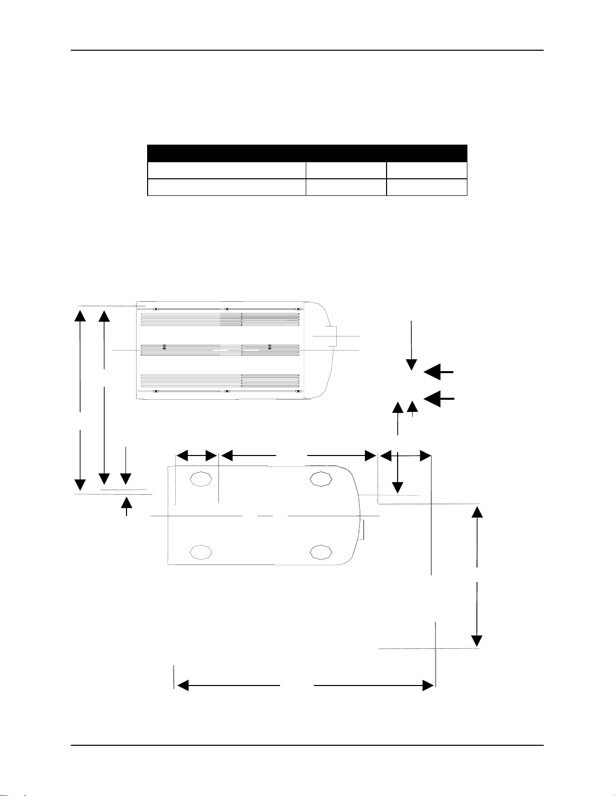
2.2. Physical Dimensions
The illustrations in this section show the footpr int and physical dimensions of the
HJT Model 100 Projector.
30.5 cm 1 foot
61.0 cm 2 feet
692.1
686.4
98.2
Figure 2.0-1 Top View M100 Projector (dimensions in mm)
5.7
155.3
558.8
Projector Centerline
348.9
183
Figure 2.0-2 Bottom View M100 Projector (dimensions in mm)
Projection Lens
Projector Centerline
511.2
2-2
946.4
Hughes-JVC Technology Company
Page 19
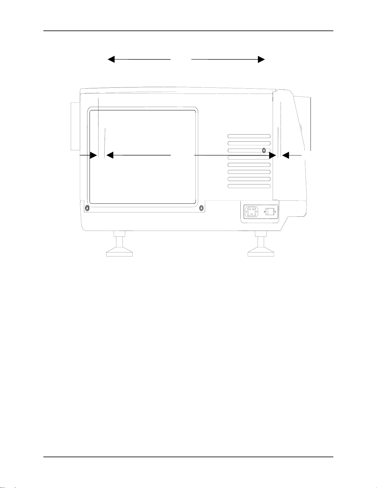
911.3
Chapter 2—Installation
35.1
897.2 14.1
Figure 2.0-3 Right Side View M100 Projector (dimensions in mm)
HJT Model 100 User's Guide
2-3
Page 20
Chapter 2—Installation
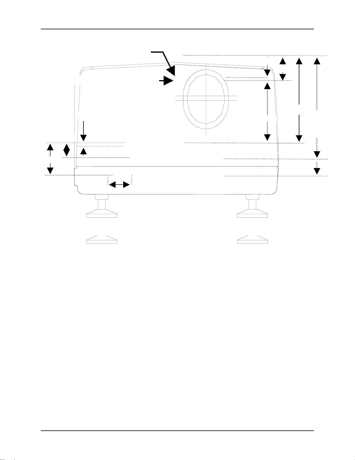
Shift 1.5:1 Projection Lens
Projection Lens Centerline
Centerline
383.7
457.9
to
502.1
Figure 2.0-4 Front View M100 Projector (dimensions in mm)
2.3. Projector Orientation
To accommodate various application requirements, the HJT Model 100 Projector
can be placed in many different orientat ions with respect to the screen. Consider
the following elements befor e inst alling the Model 100 to optimize the layout of
the theater, meeting room, or projection booth.
Projector-to-Screen distance and alignment.
Screen size.
View seating arrangements.
Lens-type selection (refer to Fig ur e 2.0-8 on page 2-8).
Physical access (see Table 2.0-2 on page 2-2).
Heat dissipation (see Table 2.0-1 Air Flow Clearances on page 2-1) .
Table or ceiling mounting.
2-4
Hughes-JVC Technology Company
Page 21
2.4. Projector-to-Screen Distance and Alignment
Set the projector to the proper distance from the screen as determined by the
screen width and lens ratio illustration (refer t o Figure 2.0-7 on page 2-7).
The Lens Pattern illustrated in Fig ure 2.0-8 on page 2-8 will help determine the
optimal screen widths and throw distances for the zoom lens.
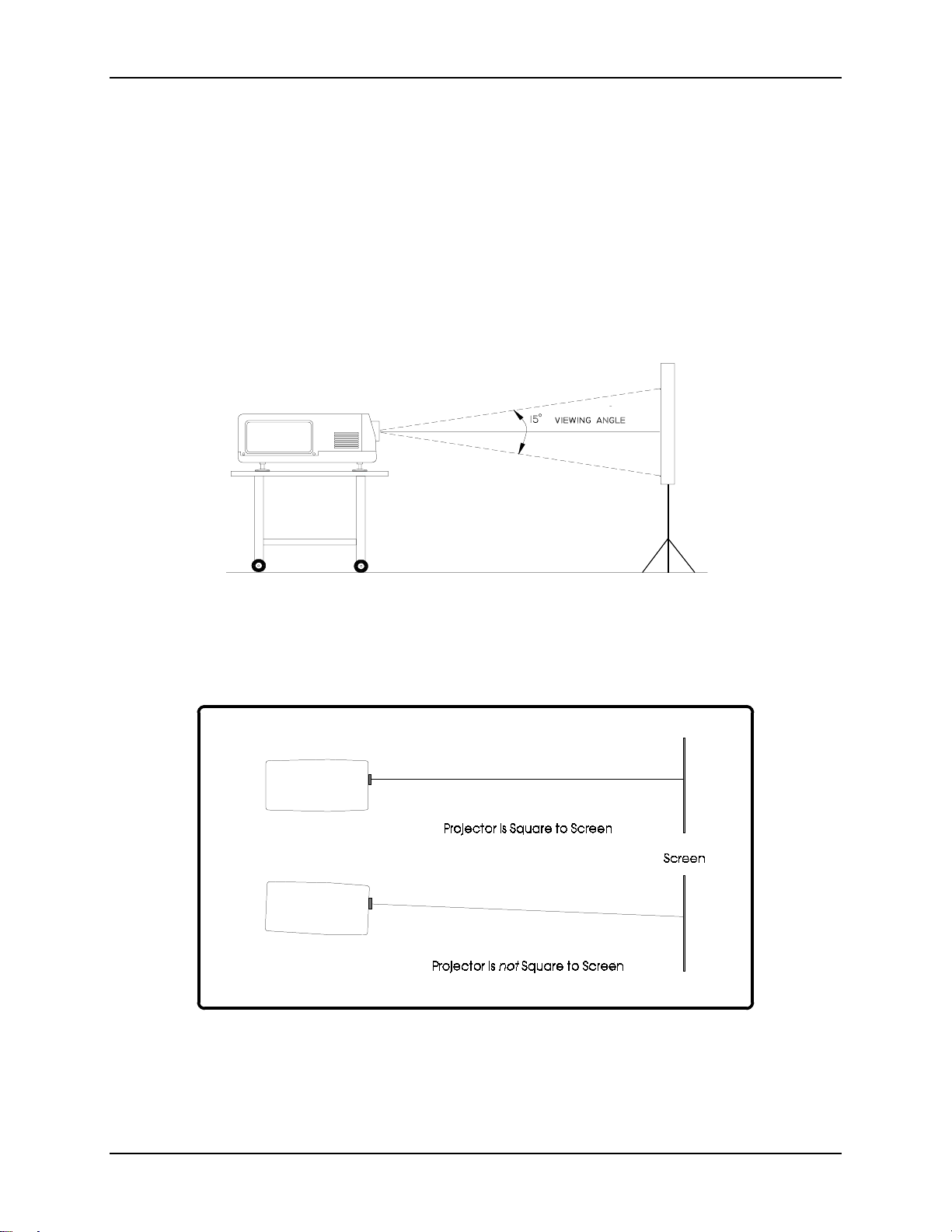
Chapter 2—Installation
The maximum
15º vertical. Any tilt greater t han 15º will result in a severe keystone error that
cannot be corrected by the Keystone adjustment.
The HJT Model 100 Projector can be used upright or downrig ht at any angle
from 5° to 85°.
projector-to-screen
vertical tilt angle for a table or ceiling mount is
Figure 2.0-5 Maximum Projector-to-Screen Vertical Tilt Angle
for table mounting, front or rear projection.
Verify that the projector is as sq uar e to the screen as possible
(no more than ± 5° from center, side-t o side, as illustrated in Figure 2.0-6).
Figure 2.0-6 Projector Square to Screen
HJT Model 100 User's Guide
2-5
Page 22
Chapter 2—Installation
2.5. Lens Throw Distance and Screen Width
The distance from the closest point of the screen to the projector is known
as the throw distance.
Table 2.0-3 Lens Definitions
Phrase Definition
Throw distance
Screen width
To determine the throw distance from the projector to the screen, mult iply the
screen width by the lens ratio.
For instance, if the project ion lens being used is the 1.5:1 lens and the desired
screen width is 3.65 meters (12 feet), t he dist ance from the closest point of the
screen to the projector lens is 5.48 met er s ( 18 feet), as illustrated in Table 2.0- 4.
Table 2.0-4 Throw Distance Calculation
Screen Width x Lens Ratio = Throw Distance
3.65 meters x 1.5 = 5.48 meters
Distance from the project or lens t o t he closest point on the screen.
Maximum width of picture that can be displayed.
12 feet x 1.5 = 18 feet
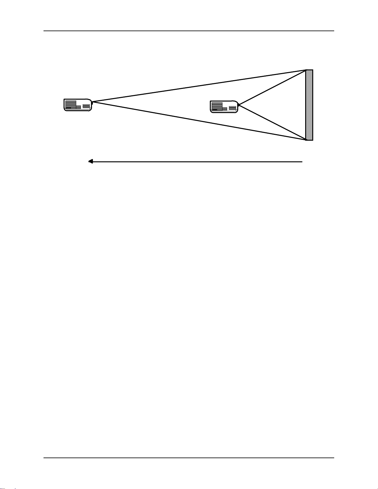
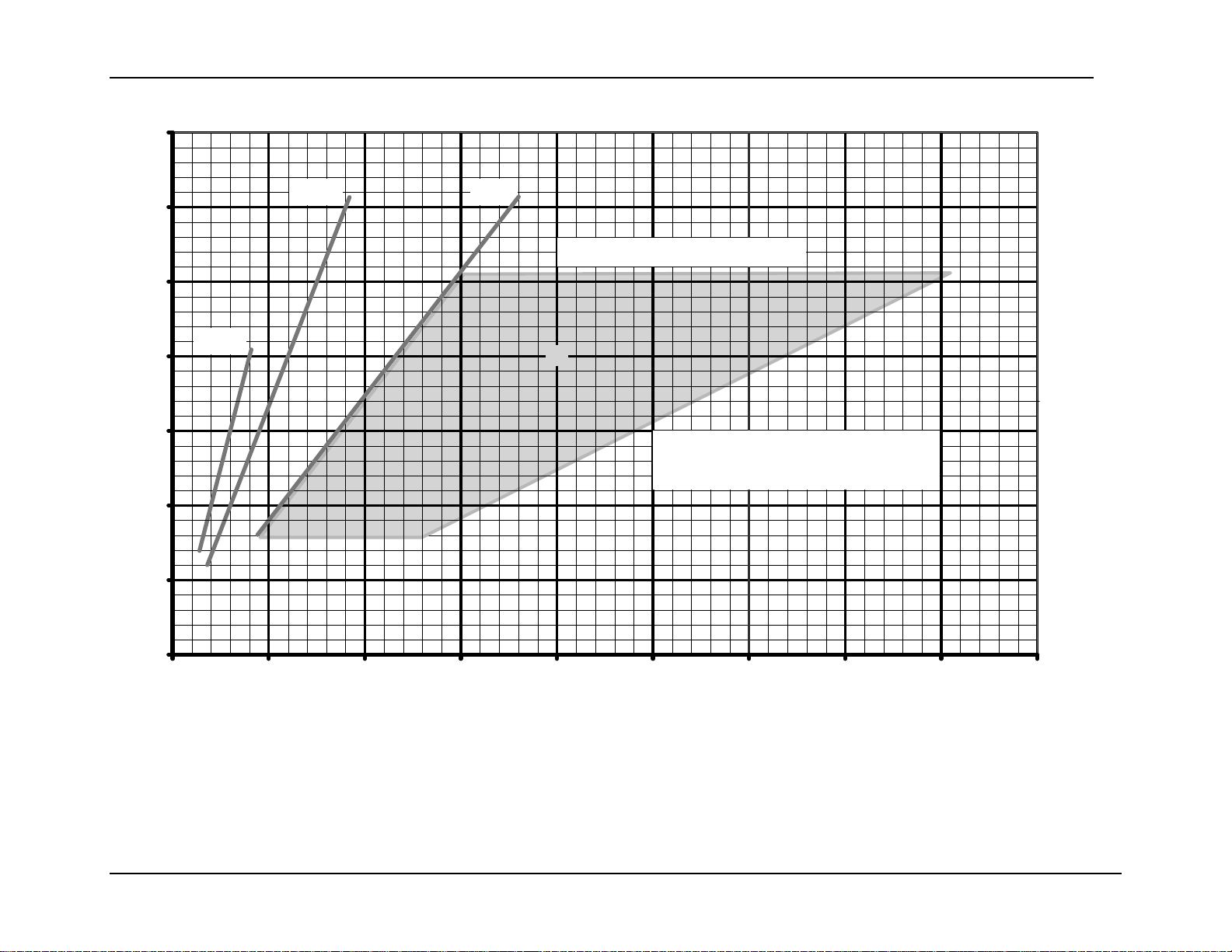
A pictorial illustration of throw distance and screen width is shown in Figure 2. 0- 7.
A graphical model is shown in Figure 2.0-8 on page 2-8. Refer to these figures for
calculating the throw distance required using the different project ion lenses
available for the HJT Model 100 Projector.
WARNING!!!
by factory Certified Technicians. Please contact your dealer or distributor
of the product for lens installation.
For special applications where the projector is not positioned orthogonally to the
screen, more detailed calculations are req uir ed t o obtain more accurate throw
distances. Special
W eb pag e at www.hjt.com
HJT Lens Calculator
Lens installation should be performed only
software can be downloaded from HJT’s
2-6
Hughes-JVC Technology Company
Page 23
3:1 LENS
1:1
LENS
Chapter 2—Installation
Screen Width = 12
Feet
36 Feet
Distance from Screen to
Projector Lens
12 Feet
Figure 2.0-7 Throw Distance vs Screen Width Illustration (3:1, 1:1 lenses)
NOTE:
100 Projectors Projection Lens Installation Guide
changing from the Zoom lens t o a fixed lens or from a fixed lens to the Zoom
lens. Lens installation must be performed only by HJT-Certified Technicians.
3:1 1:1
Refer to the
HJT Series 100 Projector Service Manual
(shipped with the lens) when
Screen Width:
3.65 meters (12 feet)
or the
HJT Series
10.97 meters (36 feet)
HJT Model 100 User's Guide
3.65 meters (12 feet)
2-7
Page 24
Chapter 2—Installation
(
)
7
Screen
Width
meters
6
5
1:1
4
3
2
1
1.5:1
3:1
Zoom Lens Ratio 3:1 to 8:1
▼
Distances are from closest point of
the screen to the projection lens.
0
0
5
10
15
20 25
30 35 40 45
Throw Distance (dimensions are in meters)
Figure 2.0-8 Lens Pattern for Model 100
The Zoom lens can be used for any screen width and throw distance points that fall inside the shaded zoom lens outline.
Zoom lens numbers represent the ratio of throw distance to screen width. A throw distance of 20 and a screen width of 4
is indicated by the in the shaded area of the chart.
2-8 HJT Model 100 User’s Guide
Page 25
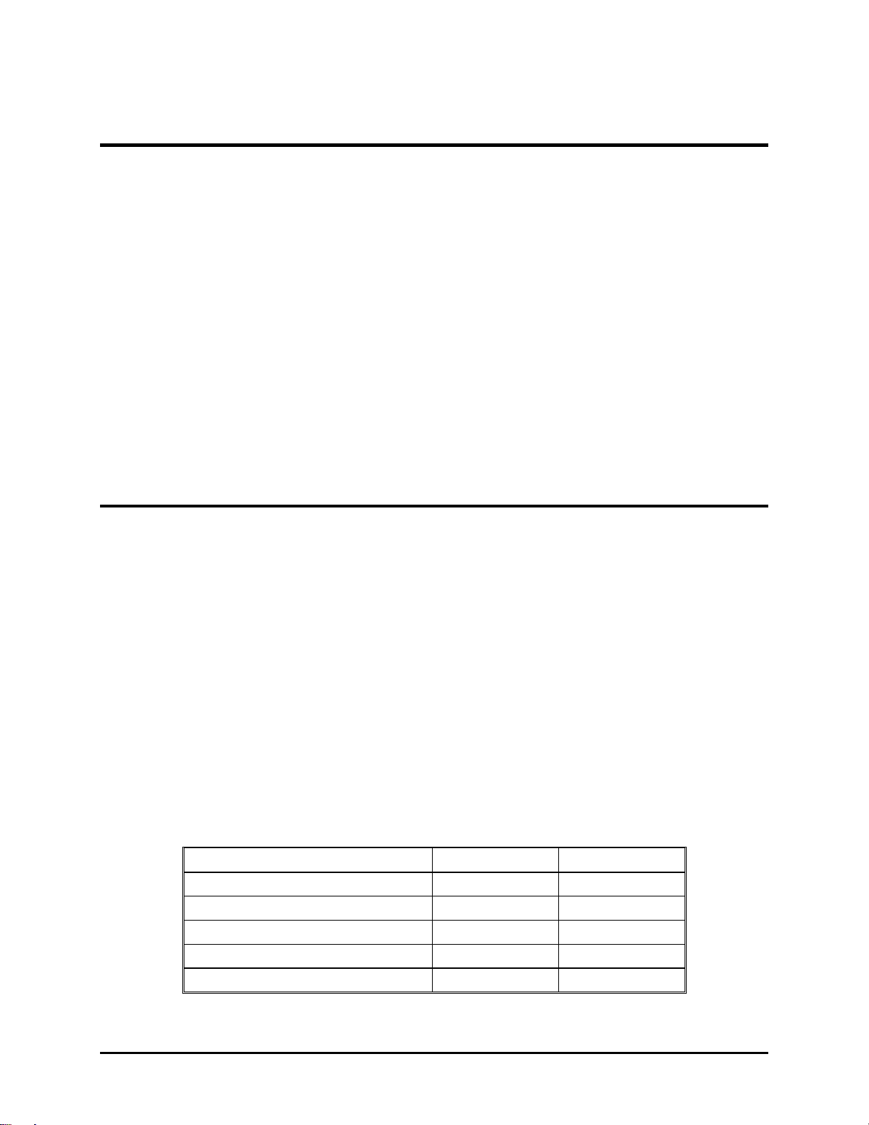
2.6. Power Requirements
Before the projector is connected to a power source, make sure that the power
source is compatible with the projector. The power sources indicated in Table 2.05 are necessary for the HJT Model 100 Projector t o oper at e effectively.
Table 2.0-5 Power Sources
Power Source
AC Voltage
Frequency
Phase
Power Cord
90 VAC ~ 132 VAC at 14 Amperes Typical;
NEMA 5-20P, 20A (plug);
NEMA 5-20R, 20A (receptacle).
200 VAC ~ 264 VAC at 7 Amperes Typical;
CEE 7/vii (plug);
CEE 7 (receptacle).
50/60 Hz
Single Phase
3-Wire, 12 AWG
Chapter 2—Installation
WARNING!!!
the HJT Model 100 Projector. Installation should be performed by an
electrician with current knowledge of electr ical codes in t he country of
use. A qualified electrician must be utilized if custom power applications
are necessary. Hughes-JVC will not be responsible for any hazards
caused by unlicensed personnel changing the original single phase,
3-wire design power connection.
2.7. Signal Sources Connection
There are two (2) basic modes of connecting signal sources to the HJT Model
100 Projector:
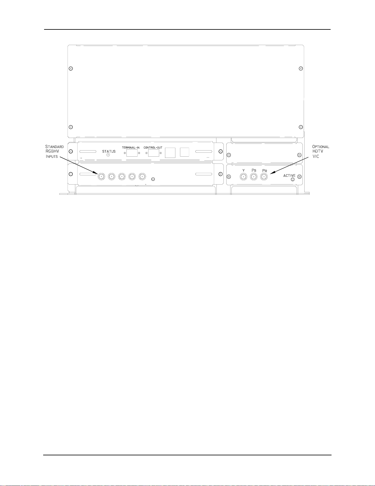
Connect the signal cables directly to the RGBHV connector s locat e d
on the right side of the proj ector as shown on Figure 2.0-9.
Connect the signal cables to an optional Video Input Card (VIC).
Optional VICs would be inserted to the right of the standard RGBHV
inputs (see Figure 2.0-9). Det a ils on connect ions and set up for the
optional VICs can be found in Section 4.11 on page 4- 39.
Always use the power cords supplied with
HJT Model 100 User's Guide 2-9
Page 26
Chapter 2—Installation
REMOTE IR IN
R G B H/CS V
RGBHV Video Input
Figure 2.0-9 Standard RGBHV and Optional HDTV Input Connections
2.7.1. Terminal or Remote Control
Verify that the remote control tether is connected to the phone jack (or a
VT100 Control Terminal is connected to t he RS-232 jack on the projector
back panel marked “Terminal In”). The other port marked “Control Out”
can also be used but must be selected from the Com m Setup menu.
The Executive IR Remote accesses all functions through the menu tree.
The Technician IR Remote can access all functions t hr ough the menu
tree but also provides access to setup functions instantly by keys on the
remote instead of navigating t hrough the menu tree.
Either remote can be used with a tether or as infrared. Drawing of the
keys on the remotes and explanations of the key functions are detailed in
Figure 3.0-1 Executive Remote Control, Figure 3.0-2 Technician Remote
Control and Table 3.0-1 Remote Contr o l Key Functions, beginning on
page 3-2.
An optional Tethered Technician LCD Remote t hat includes the addition
of a four (4) line display is also available.
2.7.2. Infrared (IR) Windows
The projector has two (2) IR windows—one in front and one in back.
These windows receive projector control signals from the IR remote.
2-10 Hughes-JVC Technology Corporation
Page 27
2.8. Sources
The projector accommodates a wide range of formats from standard composite
video to a multitude of computer g r aphics st andard. It is critical to set up the
projector’s source files to accommodate this range. Key parameters are the
horizontal and vertical scan rates, interlaced or non-inter laced scanning , and
plus/minus sync levels. The projector can handle up to 20 sources in one
channel. The correct projector sour ce file is matched and automatically selected
for the source being received by the project or .
2.8.1. Types of Standard Composite Signals
There are a number of different standards for composite video.
These standards differ in r elat ion t o par am eters such as signal timing and
the encoding scheme for the "video" information.
Table 2.0-6 Standard Composite Signals
Signal Description
NTSC 3.58/4.43
PAL and
SECAM
RS-170
NOTE:
SECAM and RS170 video only through the Quad Standard
Decoder Module (with Line Doubler) VIC option, or via an
External Scan Converter/Line Doubler or Quadrupler.
The most common for US consum er television.
Standards used in Europe and Asia.
Closed circuit monochrome.
The HJT Model 100 Projector can display NTSC, PAL,
Chapter 2—Installation
2.8.2. Red, Green and Blue Analog Signals
The most common input is separate red, green and blue (RGB) analog
signals. The sync signals for RGB analog sources can be separate
horizontal and vertical, composite (horizontal and vertical combined) or
included with the green analog signal (sync on green).
2.8.2.1. Signal Inputs
The projector allows the source(s) to be connect ed dir ectly to the
projector via appropriate connecting cables. Sig nal input jacks
are located on the projector’s rear panel ( see Figure 2.0-9
Standard RGBHV and Optional HDTV Input Connections on page
2-10).
Connect the appropriate source inputs to the appropriate jacks on
the rear panel of the project or. RGBHV is the standard input that
is supplied with the projector. Other VIC options are available
(refer to list on pag e 1- 4) .
NOTE:
If using an Extron switcher, connect it to either Port A or Port B.
A switcher can be connected to either port but only one (1)
switcher can be used. The switcher must be selected under
Connect composite sync (H/V) to the H input on the rear panel.
HJT Model 100 User's Guide 2-11
Page 28

Chapter 2—Installation
Comm Setup (see Section 3.6 on page 3-8 about Navigat ing the
Menu in reference to video switchers).
If using a communications controller such as an AMX or Crestron,
connect it to either port A or port B. Use only one (1) controller per
projector.
2-12 Hughes-JVC Technology Corporation
Page 29

3.0
Operation
Contents
3.1. Executive Remote..............................................................................................3-1
3.2. Technician Remote ............................................................................................3-3
3.3. Power ON and OFF...........................................................................................3-6
3.4. Displaying Internal Test Patterns.......................................................................3-6
3.5. Displaying External Signals................................................................................3-7
3.5.1. Internal Source..........................................................................................3-8
3.6. Navigating the Menu..........................................................................................3-8
3.6.1. Displaying the Main Menu.........................................................................3-9
3.6.2. Choosing Numbered Menus......................................................................3-9
3.6.3. To Choose Full or Short Menus................................................................3-9
3.6.4. Menu Selection Examples.........................................................................3-10
3.7. Full Menu Structure ...........................................................................................3-12
3.8. Selecting a Channel...........................................................................................3-12
3.8.1. Active Channel..........................................................................................3-13
3.9. Attaching a Source ............................................................................................3-14
3.10. Picture Settings................................................................................................3-16
3.11. Menu Item Definitions......................................................................................3-17
3.12. Short Menu Structure.......................................................................................3-21
3.13. PC or VT-100 Terminal Control........................................................................3-22
3.13.1. Terminal Preferences..............................................................................3-22
3.13.2. Communications Protocol .......................................................................3-23
The HJT Model 100 Projector can be controlled by the Executive IR remote, the
Technician IR remote or a computer. One of these IR remote controllers is supplied with
the projector. Both remotes per form the same functions when operated through the
menu tree. This chapter assumes the projector is being operated using the Executive
Remote control.
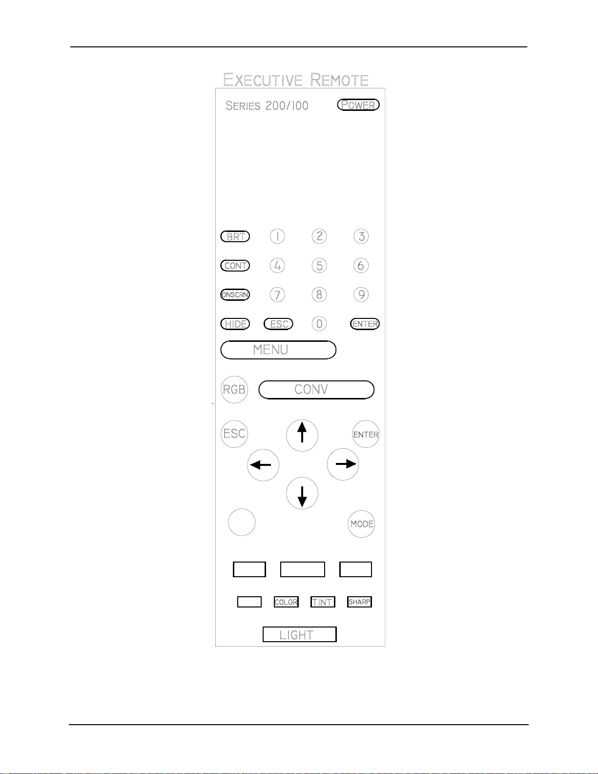
3.1. Executive Remote
The Executive Remote Control can be used as an infrared or t ethered remote
(see Figure 3.0-1 on page 3-2) . I f using the Executive remote as an IR, do not
plug in the tether cable. If using with the tether, plug one end of t he 8 meter tether
cable into the remote and the other end into t he phone jack (see Figure 3-8) on
the projector’s rear panel. One (1) end of the tether cable is terminated in a phone
jack and the other end has a telephone jack. The IR function is disabled when the
tether cable is plugged into the r em ote. All setup, image, and raster adjustments
are made with the Executive Remote by navigating through the m enu t ree (refer
to Menu Structure Diagram, Figur e 3.0-3 on page 3-11).
The Executive Remote has a maximum range of about 16 m et e r s (line of sight
only) when using the IR transmitter. It does not transmit effectively through a
rear-screen window.
HJT Model 100 User's Guide 3-1
Page 30
Chapter 2—Installation
Figure 3.0-1 Executive Remote Control
Descriptions of key functions can be found in Table 3.0-1on page 3-5.
3-2 Hughes-JVC Technology Corporation
Page 31

3.2. Technician Remote
The Technician Remote provides quicker access t o som e functions by using keys
on the remote. In the Menu Structure Diagram (Figure 3.0-3 on page 3-11) , these
direct access functions are indicated by a
access features eliminate the need to access functions via the menu structure
and save time during set up.
The Technician Remote can be used as an IR remote or with a tet her like the
Standard Remote. An 8 meter tether cable is provided with the Technician
Remote. Inserting the t ether cable disables the IR transmitter. See Figure 3.0-2
on page 3-4 for an illustrat ion of the Technician Remote control keys and Table
3.0-1 on page 3-5 for k ey function and usage.
The Technician Remote has a maximum range of about 16 meters, line-of - s ight,
when using an IR transmitter. It does not transmit effectively through a rear screen window.
Chapter 2—Installation
symbol after the function nam e. Dir ect
HJT Model 100 User's Guide 3-3
Page 32

Chapter 2—Installation
Figure 3.0-2 Technician Remote Control
Descriptions of key functions can be found in Table 3.0-1on page 3-5.
3-4 Hughes-JVC Technology Corporation
Page 33

Chapter 2—Installation
Table 3.0-1 Remote Control Key Functions
Key Function Usage
Power
Menu
Escape
Enter
Cont
Bright
Arrows
Phase
Blank
Size
Center
Onscrn
RGB
Hide
Lin
Edge Lin
Mode
XYReg
Numbers
Thresh
Sens
Pin
Key
Bow
Skew
Lens
Pattern
Press ON to turn power on, and OFF to turn power off. Press to turn power on or off.
Toggles on/off M
AIN MENU
display. Press once to display M
second time to hide M
Cancels last command and retreats one menu level,
Press to back out of current menu.
cancels an input, exits adjustment
Implements commands, chooses an item exits an
Press E
adjustment, goes to next menu level
Contrast. Change the amount of image intensity. Press C
NTER
when selection is
highlighted or to exit an adjustment.
ONT
+ left/right arrows to set
level.
RIGHT
Brightness. Adjust until black portions of a projected
image are black, but detail in color balanced areas
Press B
brightness level.
+ left/right arrows to set
is not lost.
Used for increasing and decreasing control levels,
cursor movement, convergence and geometry
Horizontal and vertical Phase adjustment of the input
image on the CRT raster.
Press P
HASE
+ left/right arrow keys to
set H phase or up/down arrows to set
V phase.
Blanking. Adjusts blanking levels at image edges.
Press once for T/L and again for B/R.
Access T/L (top/left) or B/R
(bottom/right) blanking from Timing.
Adjust with arrows.
Adjusts projected image height and width on screen. Press S
Adjusts image raster horizontally and vertically on
Use up/down and left/right arrows to
screen.
IZE
center.
+ arrows to set ht/width.
Toggles on/off the "on screen" information display. Toggles “on screen” display O
Color selection to adjust or hide Toggle to desired color.
Blanks CRTs for all colors or selected color. Toggles video or selected color on or
off.
IN
Horizontal and Vertical Linearity correction for improper
Press L
grid spacing on an image.
Edge Linearity. Horizontal and Vertical edge linearity
Press E
correction for improper grid spacing at image sides.
Provides menu to edit Channels or Sources lists. Press to edit C
Enters Registration (XY) convergence adjustment. Press XYR
Selects the input signal channel and makes Menu
Press channel or menu number.
+ Left/Right or Up/Down
arrows to correct linearity distortion.
DGE
+ Left/Right or Up/Down key
to correct edge linearity distortion.
HANNELS
EG
. See Section 4.6.
selections.
Enters Threshold convergence adjustment. Press T
Enters Sensitivity convergence adjustment. Press S
Vertical and horizontal pincushion correction for
Press P
distortion at the sides or top and bottom of an image
Keystone. Horizontal and vertical keystone correction for
Press K
grid line distortion at the sides or top and bottom of
an image with respect to the center line
Adjust picture bowing Press B
Corrects for slight yoke rotati on. Press S
Projection lens Zoom/Focus. Press L
HRESH
. See Section 4.8.2.
ENS
. See Section 4.8.1.
IN
+ arrows to correct vertical
and horizontal pincushion distortion.
EY
+ left/right or up/down keys to
correct horizontal or vertical
keystoning.
OW
-use arrows to correct.
KEW
-use arrows to corre ct.
ENS
. Up/down arrows to zoom.
Left/right arrows to focus.
Displays test pattern menu. Press P
ATTERN
. Select a test pattern.
AIN MENU
AIN MENU
N/OFF
OURCES
or S
,
.
.
.
Bulleted keys are available on both the Standard and Technician Remot es.
HJT Model 100 User's Guide 3-5
Page 34

Chapter 2—Installation
3.3. Power ON and OFF
CAUTION!!!
thoroughly read the safety guidelines outlined at the beginning of this
operator’s manual.
Before applying power to the projector
NOTE
cooling fans stay on for five (5) minutes to cool the lamp.
projector or turn of f the circuit breaker until these fans have stopped running.
Verify that the projector is connected to a 90-132 VAC, 200-264VAC, 20/10 Amp,
single-phase, 50/60 Hz AC power source.
To turn ON projector power:
1. Toggle circuit breaker on side panel t o ON. The LED light on the right of the
2. Pr ess t he P
3.
4. The orange LED should now glow green as the projector turns ON.
5.
: When the projector is turned OFF, the xenon arc lamp is turned off but the
projector glows orange.
OWER KEY
NOTE:
turning power off, this LED will blink again. The LED must stop blinking
before power to projector can be turned on again.
A Hughes-JVC logo may appear on the screen f or five (5) seconds.
The screen then displays the external video or goes blank if no video signal
is present.
NOTE:
deselect, if desired.
The same P
Hughes-JVC logo is a default set t ing. Access P
on the IR remote.
OWER KEY
also turns the projector power off. When
3.4. Displaying Internal Test Patterns
Do Not
unplug the
REFERENCE MENU
to
As a quick way to make sure that the projector is working correctly, the HJT
Model 100 Projector has nine (9) internally generated test patterns. Table 3.0-2
lists patterns available and how they are used to perform adjust m ents on the HJT
Model 100 Projector. The test patterns are accessed through the M
S
YSTEM MENU
.
AIN MENU
and
Table 3.0-2 Internal Test Patterns
# Description Purpose
No test pattern available
1
RGB X-hatch XY Convergence.
2
3
4
5
6
7
8
3-6 Hughes-JVC Technology Corporation
Cont/Bright Adjust proper Contrast and Brightness while viewing external video.
Variable Flat Adjust Thr e shold and Sensit ivity.
X-hatch Adjust Linearity, Edge Linearity, Keystone, Keystone Balance,
Focus Adjust Projection Lens and Electronic focus.
Grey/Pluge Adjust Black level (G2) and Color Balance.
Center/Lin Use for Size adjustment when using Internal source only.
External Signal. Used to adjust Phase, Cent er ing, Blanking, and Size.
Pincushion, Pincushion Balance, Bow, and Skew.
Page 35

Chapter 2—Installation
9
Grey Color Balance (Gamma).
To display an internal test pattern:
1. Select M
2. Select S
3. Select T
4. Select desir ed T
on remote.
ENU
YSTEM
EST PATTERN
from M
EST PATTERN
AIN MENU
from S
shown on screen.
YSTEM
Menu.
to be displayed.
3.5. Displaying External Signals
The internal test pattern on the scr een shows that t he pr ojector is working
properly. An external signal can now be displayed.
The HJT Model 100 Projector has four (4) factory-preset channels. The operator
can select one (1) of these preset channels to automatically display four (4) of the
standard signals currently used. These signals have been stor ed in Channel 1.
The operator can view the name and characteristics of these sources by selecting
and then selecting C
M
ENU
HANNEL
factory-preset channels menu.
Table 3.0-3 On-Screen Factory-Preset Channel Menu Display
CHANNELS CH 1 [INT]
# Name VIC Sources
1 Facto 1.1 VGA
2 . . . . . . . . .
3 . . . . . . . . .
4 . . . . . . . . .
.Table 3.0-3 shows the on-screen display of the
XGA
SXGA
81.1kHz
Table 3.0-4 defines designations displayed in Table 3. 0-4.
Table 3.0-4 Factory-Preset Channels Menu Display Definitions
Display Description
CH1 [INT]
#
Name
VIC
Sources
HJT Model 100 User's Guide 3-7
Indicates channel # selected from 0 to 99.
Lists the channel numbers.
F
Name given to that channel # (using up to 5 charact er s i. e.
ACTO
for Factory).
Video input port the external signals must be connected to. Default is 1.1 with no
optional VICs used. With optional VICs this could be 2.1, 2.2 , 2.3 or 2. 4.
Type of signal that have been program m ed int o the respective channels.
In this case, Channel 1 contains four (4) signal sources types.
Page 36
Chapter 2—Installation
To see a more detailed description of t he t ype of signal sources stored in
channel 1, access the list of sources:
Select M
Select S
ENU
OURCES
Table 3.0-5 describes the Source Menu displayed on the screen.
Table 3.0-5 Source Menu
Source Description
VGA
XGA
SXGA
81.1kHz
This signal type is popular with early computers and
operates at 31.5 kHz / 60 Hz.
This same signal is compatible with scan doubled NTSC video signals.
This signal is 1024 x 768 pixels. The nominal horizontal frequency is 48 kHz
and the nominal vertical frequency is 60 Hz.
This signal is 1280 x 1024 pixels. The nominal horizontal frequency is 64 kHz
and the nominal vertical frequency is 60 Hz.
This signal is 1600 x 1200 pixels. The nominal horizontal frequency is 81.1 kHz
and the nominal vertical frequency is 76 Hz.
NOTE:
To use a factory-preset source file, first copy it to another source number
to keep it intact for future, then use Backing up Sett ings procedure on page 4-38.
To use a factory-preset source file:
1. Highlight the channel with the desired source file and att ach it to the
highlighted channel (see Section 3.8 on pag e 3- 12) .
2. Not e t hat any adjust m ents to the “attached” source will also alter the data
from the original factory source file.
3.5.1. Internal Source
Every channel has a preset internal source shown as S
S
OURCES
list. This is factory set “default timing” for the projector with
scanning rates of 33.3k Hz (horizontal) and 59.3Hz (vertical) and is similar
to HDTV. This internal source is used t o display menus when there is no
source input connected to the projector. To use this internal source,
select C
HANNEL
to any other channel but it cannot be cut, edited, or past ed to.
3.6. Navigating the Menu
The basic procedure for navigating the menu is explained on the top left of Figure
3.0-3 Menu Structure Diagram on page 3- 11. Examples for displaying the menu,
making preference select ions, and set up selections are shown in the following
sections.
0, then press E
OURCE
. This internal source can be copied
NTER
0 on the
3-8 Hughes-JVC Technology Corporation
Page 37

3.6.1. Displaying the Main Menu
Chapter 2—Installation
The M
AIN MENU
is displayed on the screen when the M
pressed. If another menu is already being shown on the screen, pr ess t he
E
SCAPE KEY
(ESC) until you get back to the M
on the screen for 60 seconds, then time out and go off the screen.
3.6.2. Choosing Numbered Menus
Menu selections are made with the remote using menus with or without
numbers. This optional selection is made under P
without numbers may be preferred when using S
Section 3.12 on page 3-21). Numbered menus allow f or faster access
and may be preferred during proj ect or set-up.
To choose numbered menus:
1. Press M
2. Use the up/down arrow keys to highlight S
(or select S
3. From the S
P
REFERENCES
S
YSTEM MENU
4. From P
toggle the N
numbers (checked box = menus with numbers).
to display the M
ENU
YSTEM
YSTEM MENU
at the M
, and press E
).
REFERENCES
UMBERED MENUS
AIN MENU
, use the arrows keys to highlight
select N
key is
ENU
. The menus stay
REFERENCES
, and press E
. Menus
(see
AIN MENU
AIN MENU
HORT MENUS
.
YSTEM
).
(or select P
NTER
UMBERED MENUS
REFERENCES
and press E
at the
NTER
box to select menus with or without
NTER
to
3.6.3. To Choose Full or Short Menus
Full menus are necessary to perform timing, geometry, convergence, and
maintenance. Short menus allow very limited menu selections such as
picture settings and channel selection. The short menu is useful for
certain situations such as:
The projector is already set up and operating ;
Frequent channel changes are occurring;
Changes in picture settings are of ten necessary.
Short menus also prevent inadvertent changes fr om occur r ing to the
timing, geometry, or converg ence set up dat a when several operators ar e
handling the remote.
To select short or full menus:
1. From the M
2. Press E
For the Full Menu Tree, see Figure 3.0-3 on pag e 3- 11.
For the Short Menu Tree, see Figure 3.0- 6 on page 3-21.
AIN MENU
to toggle to full or shor t m enus (checked box = full menus).
NTER
Unless otherwise noted, the procedures in this manual use the Executive
or Technician remote, the menu t r ee and num ber ed, full menus.
select F
ULL MENUS
.
HJT Model 100 User's Guide 3-9
Page 38

Chapter 2—Installation
3.6.4. Menu Selection Examples
Three (3) examples of selections made using numbered menus follow.
See Figure 3.0-3 on page 3-11 for a Menu Structure Diagram.
To select the test pattern for Linearity:
1. Press M
ENU
2. Select the S
3. From the S
4. From the T
(and E
YSTEM
YSTEM
EST PATTERN
SCAPE
menu.
menu, select T
, if necessary) to display the M
EST PATTERN
list, select X-
HATCH
.
.
AIN MENU
5. The standard crosshatch test pattern appear s on t he scr een.
To select Linearity for adjustment purposes:
(Continue from the above test pattern selection.)
1. Press M
2. Select the G
3. From the G
and/or E
ENU
EOMETRY
EOMETRY
SCAPE
to display the M
menu.
menu, select L
INEARITY
AIN MENU
.
.
4. The Linearity adjustment window appears on the screen.
NOTE:
For example, when in the S
go to #4, T
It is also possible to move from side to side in t he m enu t ree.
YSTEM
, (above second example) press the left arrow three
IMING
menu, #7, (above first example) to
(3) times to move three (3) places to the left. To move back to the
S
menu, press the right arrow three (3) times. During setup
YSTEM
adjustments this featur e can save time when moving between Picture,
Timing, Geometry, and Convergence.
To select a Video Switcher:
.
1. Under M
ENU SETUP
, Port A or Port B device, select V
IDEO SWITCHER
.
2. Select a baud speed of 9600 if the switcher is connected to Por t A
OR a speed of 19200 if the switcher is connected to Por t B.
NOTE:
This allows for B
Switchers are recommended to be connected to Port B.
OOT MANAGER
to be connected to Port A through t he
ANSI terminal when software upgrades are needed without the need
for reconfiguring the ports.
3. Turn power off with the remote, or PC to shut the system down.
4. Restart the system to activate changes (cycle AC power off and back on).
Add a third digit to VIC channel assignm ent to show that a switcher is
being used (see Section 4.11 on page 4-39 about Video I nput Car ds).
3-10 Hughes-JVC Technology Corporation
Page 39

Chapter 3—Operation
Figure 3.0-3 Menu Structure Diagram
Navigating the Menu:
ENU
Press M
the M
on the Remote (or spacebar on a PC) to display
AIN MENU
. Press the number of the menu item needed
(or use arrow keys to scroll to the item, then press E
From the submenus, press the number of the selection
wanted. To move side to side within any group (such as
from the P
the P
ICTURE MENU
REFERENCES MENU
to the C
to the T
ONVERGENCE MENU
EST PATTERNS MENU
the right or left arrow keys.
HANNELS
ICTURE
1. P
1. Brightness
2. Contrast
3. Tint
4. Color
5. Sharpness
6. Black Enhance
7. VIC Setting...
# Name VIC Sources
0 Internal
1 Facto 1.1 VGA
2. C
#NameH V
0 Internal 33.3kHz 59.3Hz
1. VGA 31.5kHz 60Hz
Pressing M (M
in the C
ODE
HANNELS or SOURCES MENU
XGA
SXGA
81.1kHz
) on the keyboard when
2. XGA 48kHz 60Hz
3. SXGA 64kHz 64Hz
4. 81.1kHz 81.1kHz 76Hz
a sub-menu to Edit, Copy, Cut or P aste any
channel or source
.
NTER
or from
) press
displays
3. S
).
OURCES
AIN MENU
M
ICTURE
1. P
HANNEL
2. C
OURCE
3. S
IMING
4. T
EOMETRY
5. G
ONVERGENCE
6. C
YSTEM
7. S
AVE CHANGES
8. S
ULL MENUS
9. F
I
1. Phase
I
2. T/L Blanking
3. B/R Blanking
4. Clamp Type
5. VTR Mode
4. T
"
IMING
"
AIN MENU
M
1. P
2. C
3. S
4. F
5. G
(Short Version)
ICTURE
HANNEL
AVE CHANGES
ULL MENUS
EOMETRY
1. Size
2. Centering
3. Keystone
4. Pincushion
5. Bow
6. Skew/Rotate
7. Linearity
8. Edge Linearity
"
6. C
1. Registration
2. Threshold Uniformity
3. Sensitivity Uniformity
4. Threshold Offset
5. Sensitivity Off set
6. Black Level (G2)
7. Reset
"
Registration
Threshold
Sensitivity
ONVERGENCE
YSTEM
7. S
1. Test Patterns
2. Projection Lens
3. Preferences
4. Communicati ons Setup
5. Factory Adjustments
6. Maint. Utilities
OMMUNICATIONS SETUP
EST PATTERNS
1. T
1. Off (External)
2. Registration Crosshat ch
3. Contrast/Brightnes s
4. Variable Flat Field
5. Standard Crosshatch
6. Focus
7. Grayscale/Pluge
8. Linearity/Centering
9. Grayscale (reversed)
ROJECTION LENS
2. P
(Zoom and Focus)
NOTE:
If a fixed throw
distance lens is us ed,
the Zoom does not
function.
REFERENCES
3. P
1. Numbered Menus
2. Display Logo
3. Shutters on Hide
4. Focus Enable
"
"
"
"
4. C
1. Port A Device
2. Port A Speed
3. Port B Device
4. Port B Speed
Port A/B Device
Device:
1. None (Default B)
2. ANSI Terminal (Default-A)
ACTORY ADJUSTMENTS
5. F
®
ILA
1.
Bias
®
ILA
2.
Sensitivity
3. CRT Focus
4. H/V Dynamic Focus
3. Video Switcher (one only)
4. Comm Controller (1 port only)
5. Tethered Remote
KEY:
Items marked with may be accessed directly with Technician Remote keys.
"
Checked boxes are shown in the default mode (
=ON).
Speed:
1. 2400
2. 9600 (Default-A & B)
3. 19200
HJT Model 100 User's Guide 3-11
AINT. UTILITIES
6. M
1. Status
2. Display System
Error log
3. Reset System Error
log
4. Export Configuration
5. Import Configuration
6. Reset Lamp Timer
IAGNOSTICS
9. D
1. Display Error Log
2. Reset Error Log
Page 40

Chapter 3—Operation
3.7. Full Menu Structure
To view the M
AIN MENU
, press M
ENU
the screen.
NOTE: If another menu is displayed, press E
M
appears.
ENU
Menu screens remain active for approximately 60 seconds, then the menu "tim es
out" and is cleared from the screen. To issue a command, press M
number of your selection.
Figure 3.0-3 on page 3-11 shows the M
For a description of each menu item see Section 3. 11 on page 3-17.
After becoming f amiliar with navigating the menu, the next step is to select a
channel. This is explained in Section 3.8 on page 3-12. Be sure that the channel
selected has a source file set up to handle the type of graphic source to be
viewed. Observe the list of sources on the selected channel to confir m t his. Refer
to 3.9 on page 3-14 for information on attaching a source. See T able 3. 0- 6 for
definitions of term s .
Table 3.0-6 Channel and Source Definitions
Term Definition
Channel
Source
Source File
An Autoselect group of up to 20 source files, using one (1) specific
VIC/switch number, set up to accept up to 20 sources with
different paramet ers such as horizontal and vertical scanning
rates, interlaced/noninterlaced scanning, ± sync levels.
A channel defines the input path for a sour ce.
A specific input format such as VGA, HDTV, NTSC etc. with a given
set of parameters such as horizontal and vertical scanning rates,
interlaced/noninterlaced scanning, and sync source/polarit y.
Data set in the projector’s memor y created to handle a specific
video source. Source files must be set up to match the specific
geometric and convergence parameters in the incoming source.
on the remote. The M
SCAPE
AIN MENU
repeatedly until the M
Structure and the submenus.
AIN MENU
displays on
AIN
and the
ENU
If there is no source file on t he selected channel to handle the source to be
viewed, the proper source file can be attached from t he source list to the selected
channel. Refer to Section 3.9 on page 3- 14 for procedures for attaching a source.
If there is no acceptable source f ile set up on any other channel to attach to the
selected channel, a source file must be created ( s et up) to handle the source to
be viewed. Procedures for setting up source files ar e covered in Chapt er 4.
3.8. Selecting a Channel
A channel is an Autoselect group of up to twenty (20) sour ce files set up to
receive different video sources within any one (1) VIC slot or port.
3-12 Hughes-JVC Technology Corporation
Page 41

Chapter 3—Operation
NOTE: The Autoselect featur e m eans t hat when the incoming source changes in
the active channel, the projector automatically selects and switches to the sour ce
file within that channel that most closely matches the incom ing source's
parameters. The channel selected must have a source file set up to handle the
type of incoming video or graphic source. T he t er m s “source” and “source file” are
often used interchangeably (refer to Table 3.0-6 for definitions).
The procedures in Chapter 4 are for setting up a new source file for a new
source. The resultant geomet r ic and converg ence data in the new source file can
then be "attached" to different channels (refer to Section 3. 9). The Geometry and
Convergence settings on these attached sources must be adjusted with care—
adjustments made on attached sources will alter the dat a for all channels
attached to the source file. Not e t hat the setup data is being shared by all
channels attached to the source file by the attached sour ce from the original
source file.
To select a Channel from the Menu System :
1. Press M
ENU
2. Pr ess #2, C
to display the M
HANNELS
from the M
AIN MENU
.
AIN MENU
.
3. Ent er channel num ber using the number keys.
4. Press E
once to highlight the selected channel. Pr ess E
NTER
NTER
again to
activate the highlighted channel. If using arrow keys, scroll to highlight the
desired channel and press E
NTER
once.
5. I f the active channel contains more than one (1) source f ile for the incoming
video source, the closest match will be automatically selected.
NOTE: If the channel number is k nown, it m ay be selected by pressing the
channel number, then pressing E
NTER
.
3.8.1. Active Channel
Press E
number will display on the screen for three (3) seconds, pr ovided the
O
NSCRN
In the C
left of the number (as long as the active channel number is on the
screen list).
NOTE: Do not confuse the active channel with the highlighted channel.
The active channel is the channel that is on screen. The highlighted
channel is the channel that has been scrolled to with the arrow keys or
selected by pressing its number and E
active by pressing E
with no numbers preceding it, and the active channel
NTER
display mode is ON.
HANNELS MENU
the active channel is shown with a pointer to the
, but has not yet been made
NTER
again.
NTER
Pressing the channel number and E
C
HANNELS
list. Pressing E
again makes it “active” (on screen) .
NTER
“highlights” the channel on the
NTER
Sources may be attached (see Section 3.9) to the highlighted channel,
while another channel is active.
The active channel is displayed in the upper right corner of the
C
HANNELS MENU
M
and active/highlighted channels.
ENU
. See Figure 3.0-4 for an illust ration of the C
HANNELS
HJT Model 100 User's Guide 3-13
Page 42
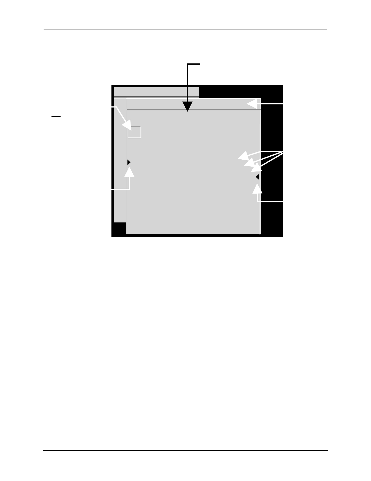
Chapter 3—Operation
y
This column shows the Video Input Card
being used for the channel and source.
The first number is t he VI C slot,
the second number is the VIC port,
and the third number is the switcher port, if any.
MAIN
Highlighted channel
not selected yet.
Move the highlight
with the arrow ke
s.
Pointer shows the active
(on screen) channel,
provided it is on the screen list.
Pointer moves to another
channel after the operator
selects a new channel
Figure 3.0-4 Channel List with Active Channel and Source
3.9. Attaching a Source
A source is defined as an input signal with a specific set of parameters such as
horizontal/vertical scan rates, interlaced or noninter laced scanning, and sync
type/polarity. An incoming source can be attached to a source file that was
previously set up for a different sour ce. The attached source is using the setup
data from the orig inal sour ce file.
CHANNELS CH 3 (SVGA2)
# Name VIC Sources
1VGA 2.1 LDNT
2RGB 1.1 LD
3SVGA 2.1 VGA
SVGA1
SVGA2
4 MAC 2.2 MAC33
MAC45
5 HD-LD 2.3 HD
6 CABLE 2.4 GRA
Indicates active channel
(CH 3) and active source
(SVGA2).
List of set-up sources
on Channel 3 (CH 3).
Pointer shows active
source (SVGA2) for CH 3.
Pointer is a tilde (~) for
an approximate
matched source.
NOTE: Setup procedures for new sources are covered beginning with
Section 4.1. on page 4-2. When setting up a source file for a new source,
the operator:
1. Connects the source to the side panel input jacks;
2. Selects the channel to receive that source;
3. Names the channel to show the source type;
4. Selects the VIC slot and/or VIC port to handle that source ( if the projector
uses an optional or a multi-port VIC);
5. Follows the adjustment procedures in Chapter 4 on page 4-37
to set up a source file to handle that specific source.
Once a source has been set up, it can be “attached” to another channel.
To “attach a source” means that an original source file and its geometry and
convergence parameters are being used by another source input signal.
3-14 Hughes-JVC Technology Corporation
Page 43

Chapter 3—Operation
The attached sources are using the same source files (they ar e the same source
files—not copies).
A source can be attached to a source file from a different channel. Geometry and
convergence settings must not be adjusted on at t ached sour ces because all
attached sources will then be altered by the same adjustment. This is only true for
geometry, convergence and ILA
®
settings. Timing and picture set t ings come into
the attached source at the default levels and may be adjusted without affecting
the original source or any other attached source.
Two (2) identical sources can be located in two (2) diff er ent channels with two (2)
distinctly different pictur e set tings for use with possibly different room
environments. For example, differ ent brightness and contrast settings could be
used for the same source in two (2) dif ferent channels, saving the time of
repeatedly adjusting contrast and bright ness.
NOTE: One channels’ source file parameters can be copied and used as st arting
points to set up new sources in other channels. The first channel may be copied
to a second channel. Follow the procedure in Section 4.10 on page 4-38 about
Backing up Settings. T he channel ( groups of source files) can be customized to
suit whatever purposes are needed.
Each channel is capable of handling up to 20 different sources. There are 99
channels (groups of source f iles) available. The maximum number of
channel/source combinations is 200.
To attach a source to a channel:
1. Press M
2. Fr om t he M
3. Fr om t he C
to display the M
ENU
AIN MENU
HANNELS
AIN MENU
select C
HANNELS
list, press the number of the channel t o attach the source
to. If the channel is not hig hlighted press E
Do not press E
if the channel is already highlighted ( t his would make the
NTER
.
.
to highlight the channel.
NTER
channel “active”).
4. Press the right arrow key to move to the S
OURCES
list.
5. Use t he ar row keys and scroll to highlight the source desired.
6. Press E
highlighted in the C
CAUTION!!!
to attach the highlighted sour ce to the channel that is
NTER
HANNELS
list.
Do not make any adjustments to geom et r y
or convergence on these “attached” sources. Any adjustm ent s will also
alter the original source file data and other attached sources.
HJT Model 100 User's Guide 3-15
Page 44
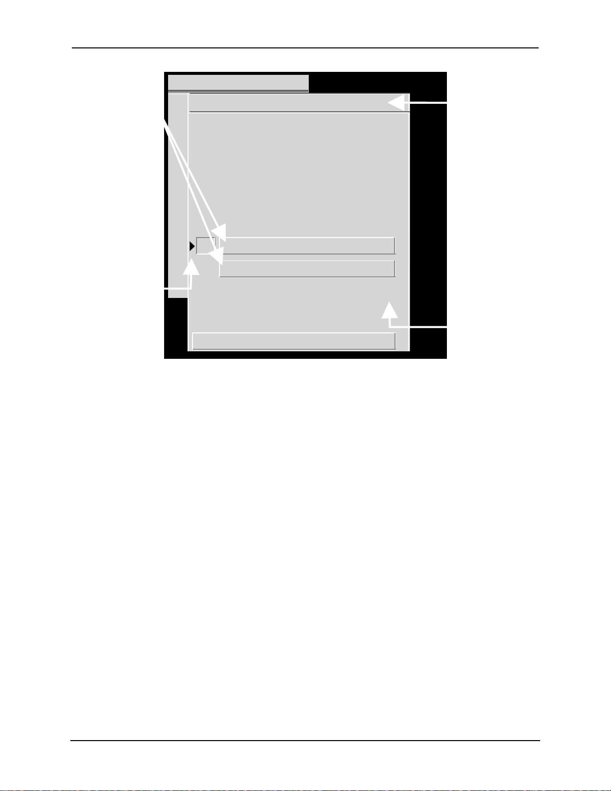
Chapter 3—Operation
e source is bla
MAIN
Highlights show valid
sources for active channel
(CH 14).
Pointer shows active source
for the channel, provided
it is visible on screen.
Pointer is a tilde (~) if sour ce
is an approximate match.
SOURCES CH 14 (HDTV)
# Name H (kHz) V (Hz) I
1PC 81.1 60 I
2 VGA 31.5 72.0
3 SVGA1 44.5 72.4
4 SVGA2 56.6 60.8
5 HD 33.5 60.2 I
6 PALLD 31.5 50.1 I
7 8514A 34.5 61.1 I
8
VIC 2.1 33.5+ 60.2+ I
Figure 3.0-5 Active and Highlighted Sources
Indicates channel
highlighted on the
C
HANNELS
list (CH 14).
Also shows source in
brackets if this hig hlighted
channel is also active
(on screen)
If the highlight ed channel
indicated here is not the
active channel,
th
nk.
This column shows if
the scan is interlaced
or not ( I = interlaced,
blank = non-interlaced).
The Active Source is the source the active channel displays on the screen,
indicated by the lower left pointer under the S
source is also displayed on the S
5. The other highlighted sour ces displayed are additional valid sources for the
highlighted channel (CH 14).
NOTE: Procedures on setting up new sources begin with Section 4.1.on page 4-2.
3.10. Picture Settings
To adjust picture settings:
1. Select #1, P
2. Pr ess t he num ber of the selection to be adjusted.
3. Use t he ar r ow keys to incr ease or decr ease t he settings for Brightness,
Contrast, Tint, Color, or Sharpness. Contrast can be adjusted by individual
color by toggling the RGB key to highlight the color desired and using t he
up/down arrow keys to adjust. Tint, Color, and Sharpness are not active on
standard RGB VICs.
NOTE: Repeatedly pressing the RGB key toggles from RGB
(all colors on screen) to Red then Green t hen Blue t hen back to all colors.
4. The B
LACK ENHANCE
image. After selecting the proper levels for the picture sett ings, select B
E
NHANCE
that provides the best black detail in the dark areas of the picture.
ICTURE
from the P
in Figure 3.0-5. The active
OURCES
from the M
OURCES
list in the upper right corner of Figure 3.0-
AIN MENU
.
feature enhances black detail in the dar k areas of the
ICTURE
menu. Use the arrow keys and select the level
LACK
3-16 Hughes-JVC Technology Corporation
Page 45

Chapter 3—Operation
3.11. Menu Item Definiti ons
This section defines the menu items available thr ough the M
submenus.
Table 3.0-7 Available Menu Items
# MAIN MENU Description
# Sub-Menu
1. P
ICTURE
1B
2C
3T
4C
5S
6B
7 VIC S
2. C
HANNELS
Displays picture adjustments and VIC settings. A small window contains the
adjustment name and the current data value. When the value is
highlighted the user may enter a new value.
RIGHTNESS
ONTRAST
INT
OLOR
HARPNESS
LACK ENHANCE
ETTING
Displays the channel numbers, channel names, VICs, and some of the
sources attached to each channel. Pressing M (
following sub-menu for editing purposes:
Description
Adjustment for pictur e br ightness.
Adjustment for picture contrast.
Adjustment for pict ure tint. (Only with optional HDTV VIC.)
Adjustment for pict ure color. (Only with optional HDTV VIC.)
Adjustment for pict ur e focus. (Only with optional HDTV VIC.)
Toggle ON or OFF to enhance black detail
Video Input Card settings.
AIN MENU
) provides the
MODE
and
1E
DIT
2C
OPY
3C
UT
4P
ASTE
Allows editing of the channel name and VIC. Right and left arrows
move the cursor to the point for edit ing, pressing enter chooses
the field to edit, up/down arrows or dialog boxes allow for
changing the character or the input por t . Pressing enter accepts
the change.
Copies (without changing) the highlighted channel’s name, VIC
path, and list of sources into the past e buffer in preparation for
pasting to another channel.
Same as copy above except that the highlighted channel is reset to
factory defaults (name is blank, VIC is unassigned and no source
is attached).
Pastes the contents of the paste buffer into the highlighted
channel. Assigns new name: CPYnn, nn = channel number of
copy.
HJT Model 100 User's Guide 3-17
Page 46

Chapter 3—Operation
# MAIN MENU Description
# Sub-Menu
3. S
4. T
OURCES
IMING
1P
2 T/L B
3 B/R B
4C
5VTR M
5. G
EOMETRY
1S
2C
3K
4P
5B
6S
7L
8E
9R
Displays input sources, horizontal and vertical rates sync type/polarity,
interlaced or noninterlaced scanning. Contains a submenu for editing,
copying, cutting or pasting any source names like the channel list menu.
Indicates active source with a pointer. Highlights the sour ces t hat are
attached to the channel that is highlig hted on the channel list.
Displays the timing menu and adjustments.
HASE
LANKING
LANKING
LAMP TYPE
ODE
Displays the following raster adjustments:
IZE
ENTERING
EYSTONE
INCUSHION
OW
KEW/ROTATE
INEARITY
DGE LINEARITY
EG ENABLE
Description
Horizontal and vertical adjustment for picture phase.
Adjustment for top/left blanking.
Adjustment for bottom/right blanking.
Pick list for type of clam ping preferred. Selections are BackPorch,
SyncTip, or TriLevel. Default is back porch.
Toggle for VTR ON or OFF. Default is OFF.
Value adjustment for width and height (All = Coarse: R & B = Fine).
Value adjustment for red, green and blue, horizontal and vertical
centering.
Value adjustment for left, right, top, and bott om keystone
correction.
Value adjustment for left, right, top, and bott om pincushion
correction.
Value adjustment for left, right, top, and bott om bow correct ion.
Value adjustment for the r ed, green and blue horizontal skew and
rotation.
Value adjustment for red, green, and blue, vertical and horizontal
linearity correction.
Value adjustment for hor izontal and vert ical edge linearity
correction.
Menu toggle to enable convergence (XY R
EGISTRATION
). This box
should be un-checked only when doing Geometry procedures or
for specific maintenance by service personnel. T he default is O
N
.
3-18 Hughes-JVC Technology Corporation
Page 47

Chapter 3—Operation
# MAIN MENU Description
# Sub-Menu
6. C
ONVERGENCE
1R
2T
3S
4T
5S
6B
7R
7. S
YSTEM
1T
2P
3P
EGISTRATION
HRESHOLD
ENSITIVITY
HRESHOLD
O
FFSET
ENSITIVITY
O
FFSET
LACK LEVEL
ESET
Displays the S
EST PATTERN
ROJECTION LENS
REFERENCES
Description
Displays the following convergence parameters:
XY adjustment for r ed, green and blue.
R, G, and B adjustment for varying the brightness of the dark
areas of the screen.
R, G, and B adjustment for varying the brightness of the br ight
areas of the screen.
R, G, and B adjustment f or offsetting the br ightness of the dark
areas of the screen.
R, G, and B adjustment for offsetting the brightness of the bright
areas of the screen.
G2 adjustment for r ed, green, and blue.
Menu for Registration, Thr eshold, and Sensitivity. Resets
Registration to 128, Threshold to 128, and Sensitivity to 128.
It is also color-selectable.
YSTEM MENU
and its six (6) submenus as shown below:
Provides selection of nine differ ent t est patterns as described in
Chapter 3.
Value adjustment for zoom and f ocus.
Allows operator to select menus with or without numbers,
S
HUTTERS ON HIDE
1N
UMBERED MENUS
2D
ISPLAY LOGO
, or F
OCUS ENABLE
Toggle O
O
N OR OFF
:
N OR OFF
. The default is ON.
. The default is ON and
displays the HJT Logoat startup.
3S
HUTTERS ON HIDE
Covers the R, G, or B ILA® assembly to
prevent the ILA
®
window from
appearing on the screen.
4F
OCUS ENABLE
When box is checked focusing is allowed.
When box is unchecked focusing is
disabled to prevent accidental focusing.
Default is O
.
N
continued
HJT Model 100 User's Guide 3-19
Page 48

Chapter 3—Operation
# MAIN MENU Description
# Sub-Menu
7. S
YSTEM
4C
5F
6M
Displays the System menu and its six submenus as shown below:
OMM SETUP
ACTORY
A
DJUSTMENTS
. U
AINT
TILITIES
Description
Menu selection for type of device for port A/ B and baud speed.
The defaults for Port A are ANSI Terminal and 9600 Baud.
The defaults for Por t B are N
and 9600 Baud.
ONE
If a Video Switcher is being used, it must be select ed for either
Port A or B from the Com m . Setup menu. Select a speed of 9600
Baud for Port A or 19200 f or Port B.
NOTE: Video Switchers and the Tethered Remote option should
be connected to Port B. This allows for Boot Manager to use an
ANSI Terminal on Port A to upgrade software without the need
for reconfiguring.
ILA
®
BIAS
Red, green, and blue ILA® light valve
1
bias adjustment. Must be done
whenever light valve components are
replaced or ILA
2
®
ILA
SENSITIVITY
Value adjustment for light valve bias
®
Sensitivity is changed.
frequency.
3 CRT F
OCUS
Value adjustment for R, G, or B CRT
focus.
4 H/V D
F
OCUS
YNAMIC
Value adjustment for horizontal and
vertical dynamic focus.
Provides a submenu below for maintenance purposes:
1S
TATUS
Displays projector parameters such as;
software revision, VIC types, channel
information, lamp hours, pr ojector
(system controller) hours.
2D
ISPLAY SYSTEM
E
RROR LOG
3R
ESET SYSTEM
E
RROR LOG
4E
XPORT
C
ONFIGURATION
Display screen for system errors.
Dialog to confirm reset .
Dialog for saving the project or ’s setup
data to an external host for backup.
This backup data can be imported
whenever a System Controller board is
replaced.
5I
MPORT
C
6R
ESET LAMP
T
ONFIGURATION
IMER
Used with #4 E
XPORT CONFIGURATION
above.
Dialog to change timer value.
3-20 Hughes-JVC Technology Corporation
Page 49

Chapter 3—Operation
# MAIN MENU Description
# Sub-Menu
8. S
AVE CHANGES
Description
M
AIN MENU
done automatically once every hour and during a P
sequence or D
O
O
FF
N
9. F
ULL MENUS
(M
ENU TOGGLE
)
3.12. Short Menu Structure
Short menus allow very limited menu selections and prevent inadvertent changes
in setup data when several operators are using the remote.
To use short menus:
1. Press M
2. Fr om t he M
to display the M
ENU
AIN MENU
M
1. P
2. C
3. S
4. F
selection saves all current parameters. This is usually
OWER-OFF
OWNLOAD CONFIGURATION
When checked t ur ns F
When checked t ur ns F
AIN MENU
.
ULL MENUS OFF
ULL MENUS ON
.
.
. Is the default setting.
, select.
AIN MENU
ICTURE
HANNEL
AVE CHANGES
ULL MENUS
(S
HORT VERSION
)
1. P
ICTURE
RIGHTNESS
1. B
ONTRAST
2. C
INT
3. T
OLOR
4. C
HARPNESS
5. S
LACK ENHANCE
6. B
7. VIC S
ETTINGS
2. C
# Name VIC Sources
1 Facto 1.1 VGA
……… … …
•
•
99 ……… … …
Figure 3.0-6 Short Menu Tree
HANNELS
XGA
SXGA
81.1kHz
HJT Model 100 User's Guide 3-21
Page 50

Chapter 3—Operation
3.13. PC or VT-100 Terminal Control
The projector can be controlled by a VT-100 terminal. If a VT-100 is not available,
a PC with W
INDOWS
3.1 or PROC
10 on page 3-23 shows the equivalent commands for the t erminal and both
remotes.
To control the projector by a PC or VT-100 Terminal:
for DOS can emulate a VT-100. Table 3. 0-
OMM
1. From W
2. Select T
INDOWS PROGRAM MANAGER
ERMINAL EMULATION
3. Select DEC VT-100(ANSI) (may already be selected).
4. Use a Null Modem cable to connect between the projector and the terminal.
5. Refer to Section 3.13.1Terminal Preferences and 3.13.2 Communications
Protocol for W
INDOWS
3.13.1. Terminal Preferences
Select S
P
REFERENCES
ETTINGS
. Set the modes as indicated in Table 3.0-8 below.
Table 3.0-8 Terminal Preferences
Modes Modes
Line Wrap
Local Echo
Sound
Columns Cursor
80
132
Terminal Font Blink
Courier 12
Terminal Show IBM to ANSI
Scroll Bars
Yes
No
Yes
Yes
No
Yes
from S
, select T
ETTINGS MENU
ERMINAL
.
setup.
again from the menu bar. Select T
CR####CR/LF
Inbound
Outbound
Block
Underline
Translations
Buffer Lines
, then S
ERMINAL
No
No
Yes
No
Yes
NONE
No
100
ETTINGS
.
Use Function Arrow and Control keys for Windows
No
3-22 Hughes-JVC Technology Corporation
Page 51

Chapter 3—Operation
3.13.2. Communications Protocol
Select S
ETTINGS
using the menu bar, then select C
Set the following communications parameter s and m odes.
Table 3.0-9 Communication Protocol
Modes Parameters
9600
8
None
No
Com1—this is PC configuration dependent
1
X
ON/XOFF
No
ILE NAME
Select F
Baud Rate
Data Bits
Parity
Parity Check
Connector
Stop Bits
Flow Control
Carrier Detect
from the menu bar and select NEW. Under F
ILE
This will allow the user to select the file VT-100. TRM with the parameters listed in
Table 3.0-9 saved for future use.
Table 3.0-10 VT-100 Terminal and Remote Command Equivalents
Action
Power OFF (All)
Power ON (All)
Power ON/O
Power ON/O
FF
FF
(Electronics only)
Power ON/OFF Lamp
Left Arrow
Right Arrow
Up Arrow
Down Arrow
Back out of menu
Blanking
Bow, H & V
Brightness
Center, H & V (RGB)
Change channel
Color
Contrast (RGB)
Edge, H & V (RGB)
Enter
Escape
Standard
Keyboard
Input
+ F 6 6
C
TRL
C
+ U 21 15
TRL
C
-P Power Power 16 10
TRL
C
+ E 5 5
TRL
C
+ L 12 0C
TRL
Remote
Keys
Left Arrow Left Arrow Left Arrow
Right Arrow Right Ar row Right Arrow
Up Arrow Up Arrow Up Arrow
Down Arrow Down Arrow Down Arrow
E
SC
E
SCAPE
B Blank 66 42
U Bow 85 55
IBright7349
P Center 80 50
Number
+ E
NTER
Channel #
+ E
NTER
Y8959
C Cont 67 43
E EdgeLin 69 45
E
NTER
Esc E
E
NTER
SCAPE
Technician
Remote
Keys
E
SCAPE
Channel #
+ E
NTER
E
NTER
E
SCAPE
OMMUNICATIONS
.
enter VT-100.TRM.
Decimal Hex
∇∇∇∇
27 91 68
27 91 67
27 91 65
27 91 66
∇∇∇∇
∇∇∇∇
∇∇∇∇
1B 5B 44
1B 5B 43
1B 5B 41
1B 5B 42
27 1B
48-57 30-39 + 0D
13 0D
27 1B
∇∇∇∇
∇∇∇∇
∇∇∇∇
∇∇∇∇
HJT Model 100 User's Guide 3-23
Page 52

Chapter 3—Operation
s
Action
Hide
Keystone, H & V
Lens adjust
Linearity, H &V (RGB)
Menu
Mode
Numeric
Onscreen
Phase
Picture sharpness
Picture tint
Pincushion, H & V
RGB toggle
Size, H & V
Test pattern display
Skew, H & V (RGB)
Threshold
Sensitivity
Registration
Redraw Terminal Screen
Reboot
∇∇∇∇
Restart System Software
The A
E
SCAPE
RROW KEYS
, L
EFT BRACKET
are a sequence of Decimal or Hex numbers repr esent ing the sequence of
, and A, B, C, or D depending on which arrow was pressed.
∇∇∇∇∇∇∇∇
C
C
The first number represents the E
Standard
Keyboard
Input
Remote
Keys
F Hide Hide 70 46
K Key 75 4B
A Lens + Arrow
L Lin 76 4C
Spacebar Menu Menu 32 20
M Mode Mode 77 4D
0-9 0-9 0-9 48-57 30-39
O Onscrn Onscrn 79 4F
H Phase 72 48
X8858
Z905A
N Pin 78 4E
RRGBRGB8252
SSize8353
T Pattern 84 54
WSkew8757
D Thresh 68 44
V Sens 86 56
G XYReg 71 47
|1247C
+Shift+_
TRL
+Shift+^
TRL
SCAPE
key, the second number represents the L
Technician
and the third number represents the let ter corresponding to the A
Remote
Keys
RROW KEY
Decimal Hex
65 41
49 31
48 30
EFT BRACKET
pressed.
,
∇∇∇∇
Refer to Section 4.12 on page 4-45 for information on updating software.
∇∇∇∇∇∇∇∇
Must be done for a software change or port configuration change (device, speed) to take effect
(see Figure 3.0-3 on page 3-11and Section 3.11 on page 3-17 about Menu Item Definitions).
3-24 Hughes-JVC Technology Corporation
Page 53

4.0 Setup Adjustments
Contents
4.1. Setup Preparation..............................................................................................4-2
4.1.1. Projection Lens Focus (Rough).................................................................4-4
4.1.2. Editing Channels, Sources, and VICs .......................................................4-5
4.1.3. Factory-Preset Channels and Sources......................................................4-7
4.1.4. Internal Source..........................................................................................4-8
4.2. Timing Settings and Adjustments ......................................................................4-8
4.2.1. Clamp Type...............................................................................................4-8
4.2.2. VTR Mode.................................................................................................4-8
4.2.3. Blanking....................................................................................................4-9
4.2.4. Phase........................................................................................................4-9
4.3. Geometric Adjustments .....................................................................................4-10
4.3.1. Centering (G)............................................................................................4-10
4.3.2. Size...........................................................................................................4-10
4.3.3. Bow...........................................................................................................4-12
4.3.4. Skew/Rotate (G) .......................................................................................4-13
4.3.5. Linearity (G)..............................................................................................4-14
4.3.6. Edge Linearity...........................................................................................4-16
4.3.7. Keystone...................................................................................................4-17
4.3.8. Pincushion................................................................................................4-18
4.3.9. Centering (Red and Blue) .........................................................................4-19
4.3.10. Linearity (R and B)..................................................................................4-19
4.3.11. Skew/Rotate (R and B)........................................................................... 4-20
4.3.12. Projection Lens Focus (Fine) ..................................................................4-20
4.4. CRT Focus and H/V Dynamic Focus.................................................................4-21
4.5. ILA
4.6. Convergence (XY Registration).........................................................................4-23
4.7. Black Level (G2) and Sensitivity Offset..............................................................4-29
4.8. Uniformity (Shading).......................................................................................... 4-31
4.9. Picture Settings .................................................................................................4-34
4.10. Backing up Settings.........................................................................................4-37
4.11. Video Input Cards............................................................................................4-38
®
Sensitivity and Bias....................................................................................4-21
4.6.1. Purpose of Convergence..........................................................................4-23
4.6.2. Cursor Shapes and Sizes..........................................................................4-23
4.6.3. Convergence Profiled................................................................................4-24
4.7.1. Black Level (G2) .......................................................................................4-29
4.7.2. Sensitivity Offset.......................................................................................4-30
4.7.3. Threshold Offset.......................................................................................4-30
4.8.1. Sensitivity Uniformity.................................................................................4-31
4.8.2. Threshold Uniformity.................................................................................4-32
4.8.3. Color Balance (Grey Scale).......................................................................4-33
4.9.1. Brightness.................................................................................................4-35
4.9.2. Contrast....................................................................................................4-35
4.9.3. Color, Tint, Sharpness..............................................................................4-36
4.9.4. Black Enhance..........................................................................................4-36
4.9.5. VIC Settings..............................................................................................4-36
4.11.1. Installing (or Removing) a VIC ................................................................4-39
HJT Model 100 User's Guide 4-1
Page 54

Chapter 4—Setup Adjustments
4.11.2. Connecting VIC Source Cables...............................................................4-40
4.11.3. VIC Editing..............................................................................................4-40
4.11.4. VIC Settings............................................................................................ 4-42
4.12. Updating Software...........................................................................................4-44
This chapter assumes the operator is using a r em ote control and accessing setup
functions through the menu t r ee. All instructions are given with reference to using t he
menu tree for setup f unctions. If using a PC or laptop computer to control the projector
refer to Table 3.0-10 on page 3-23 for the equivalent key f unct ions.
Chapter 3 covered mainly operation for project o r s that are already positioned, set up,
and ready for operation. This chapter covers the com plet e projector setup procedures.
Prior to starting the procedur es in t his chapter, the operator should review Chapter 3 to
become familiar with navigating the m enu and using the remote control keys.
Prior to performing any adjust ments, allow the projector to warm up for at least 60 minutes.
4.1. Setup Preparation
In the Timing and Geometric adjustments below, Green is the active and
on-screen color. Red and Blue are hidden because they track on Gr een.
When the T im ing and Geometric adjustments in this section are finished,
Red and Blue is then centered to match Green and converged onto Green in the
Convergence procedures. To hide Red and Blue, tog gle the RGB key to R
press H
displayed on the screen. Toggle the RGB
, then toggle to B
IDE
and press H
LUE
. Green is now the only color
IDE
to highlight G.
KEY
ED
,
To avoid redundancy in the procedures in this chapter, some gener al information,
instructions, phrases, and definit ions ar e given below.
Table 4.0-1 Setup Phrases, Definitions, and General Information
Phrase Definition
R, G, or B
Toggle to
Red/Green/Blue
Access an item
from the menu
Hide a color
Active
Inactive
Highlighted
Red, Green or Blue.
Pressing the RGB key repeatedly until the desir ed color is select ed by
observing the highlight on the RGB window on the screen.
Pressing M
ENU
and/or E
SCAPE
keys to display the M
then pressing the number of the menu or item desired.
Highlight color with the RGB tog gle, then press the H
The active channel is the one on the screen.
The inactive channel has either no input connected or
no signal coming in to its input or is not act ive (on screen) .
The channel selected by pressing a channel number
but not yet activated by pressing E
NTER
.
Pressing the channel number highlights the channel on the channel
list.
Pressing E
makes it active on screen.
NTER
Figure 4.0-1on page 4-7 illustr ates an active and highlighted
channel.
AIN MENU
key.
IDE
, and
4-2 Hughes-JVC Technology Corporation
Page 55

Chapter 4—Setup Adjustments
HJT Model 100 User's Guide 4-3
Page 56

Chapter 4—Setup Adjustments
Adjustment Explaination
R, G or B
Adjustments
Adjustments can be performed on individual colors if the RGB letters
are in the window on the screen. Selecting one (1) color makes it
adjustable but all three (3) colors st ill r emain on the screen (unless
For any
Adjustment
End of any Timing
hidden by the H
Pressing E
Pressing M
Press M
Press E
SCAPE
ODE
ODE
NTER
again to toggle back t o the single digit adjustment rate.
or E
key).
IDE
immediately removes RGB displays.
speeds up the adjustment by a 4 to 1 ratio.
SCAPE
to exit.
or Geometry
Adjustment
Convergence
Adjustments
Performing
Pressing E
M
OVE/SIZE
Press E
SCAPE
while performing Convergence changes the
NTER
mode to the A
DJUST
to exit the adjustment.
Convergence
Procedures
mode.
General Information
Verify that O
NSCRN
key is toggled to ON if the screen does not show
the window or menu correctly.
When performing ILA® S
S
ENSITIVITY OFFSET
S
HUTTERS ON HIDE
checked. Checking this box activates the shutter m echanism t o
hide the ILA
®
images and provides easier, more accurate sett ing s
ENSITIVITY AND BIAS
, and U
NIFORMITY (SHADING
box under the S
YSTEM-PREFERENCES
, B
LACK LEVEL
), verify that the
(G2),
menu is
of these adjustments.
On single-axis adjustments such as P
T
HRESHOLD
, S
ENSITIVITY
, ILA® B
IAS
ICTURE SETTINGS
etc. up/down arrow keys are
, G2,
shown on the screen—left/right ar r ow keys, t hough not shown, will
also accomplish the same adjustments.
After completing the t iming, geometric, and convergence adjustments for one (1)
source, the adjustment data may be backed up by copying the channel t o anot her
of the 99 channels and the source file to anot her of the 20 sources.
NOTE: When backing up a channel, ensure that the “copied to” channel is blank .
Channel paste is only allowed to “cut” empty channel. Source paste will overwrite
current source geometry, convergence and ILA
®
settings. All data will be deleted
on the “copied to” channel. Refer to t he Backing up Settings function from Section
4.10 on page 4-38 for mor e det ail.
This provides backup for a previously set up channel and a good star t ing point for
setting up other channels. Also ensure that t he " c opied t o" channel uses the
same type of VIC as the "copied fr om" channel. If the projector uses only one (1)
VIC, this is not applicable.
4-4 Hughes-JVC Technology Corporation
Page 57

Chapter 4—Setup Adjustments
If the projector uses m or e than one (1) type of VIC, the type can be determined
by accessing the S
YSTEM-MAINTENANCE
menu and selecting S
TATUS LIST
. Each
VIC slot will be displayed with the type of VIC in each slot. Complete the Timing
section first, Geometr y next, and Converg ence last .
They are performed in this order because Geometry depends on proper Timing
settings and Convergence depends on correct Geometry.
Ensure that the projector is installed and positioned correctly at the outset so that
all later adjustments will be at their opt im al levels and the image will be the
sharpest possible. Positioning the projector is the most important step in the
setup procedures. The projector- to-screen alignment should be as square as
possible before starting setup procedures in order to accomplish Timing,
Geometric, and Convergence adjustments properly.
Prior to starting the procedur es, a channel and sour ce (source file) must be
selected for the setup adjustm ent s. This is covered in Section 4.1.2 on page 4-6.
A rough focus of the pr ojection lens may be necessary to be able to read the
menus.
4.1.1. Projection Lens Focus (Rough)
For the Timing and Geometry setup procedures below, it is necessary to
obtain a rough focus of t he Pr ojection Lens in order to read menus and
do the adjustments. If t he focus is adequate to read the menus, this
procedure can be skipped until after the Timing and Geometry
adjustments are finished. When the Timing and Geometry adjustments
are complete, and prior to start ing conver gence, t he Projection Lens
focus adjustment should be repeated and a sharp focus obtained.
To obtain a Rough Focus of the Projection Lens:
1. Press M
If necessary, use the E
2. Select S
3. Select T
4. Select F
NOTE: The H pattern is pref er red for focusing the Projection Lens.
5. Select P
6. A small window displaying F
to display the M
ENU
YSTEM
EST PATTERN
OCUS
ROJECTION LENS
from the M
from the S
from the T
AIN MENU
SCAPE
key to back out to the M
AIN MENU
EST PATTERN
from the S
OCUS
on the screen.
.
YSTEM
menu.
menu.
YSTEM
and Z
OOM
AIN MENU
menu.
arrows appears on the
.
screen.
7. Use the up/down arrow keys to zoom the image to the desired size.
The raster and image should be smaller t han t he screen. Ensure the
F
OCUS ENABLE
box in the P
REFERENCES
menu is checked.
8. Use the right/left ar r ow keys to get a rough overall focus to be able to
read menus. A sharper focus will be obtained later after the Geometry
procedures are completed.
9. Press E
10. Press E
to complete this adjustment.
NTER
SCAPE
twice to display the M
AIN MENU
.
HJT Model 100 User's Guide 4-5
Page 58

Chapter 4—Setup Adjustments
4.1.2. Editing Channels, Sources, and VICs
Select C
HANNEL
(see Section 3.8 on page 3-12). Edit t he C
and S
OURCE
files from the C
HANNELS
HANNELS
’ and S
and S
OURCES
OURCES
select a name for the new channel, VIC, and source. Figure 4.0-1and
Figure 4.0-2 illustrate t he C
HANNELS
and S
OURCES
’ lists showing “active”
and “highlighted” channels and sources. Verify that the projector is
receiving the appropriate source.
CAUTION!!!
If the active channel receives a source that
does not have an exact match in a source file, the projector will match the
source to the source file that is closest t o the new source parameters. If
adjustments are attempted, t he following statement appears on the
screen: “Adjustments are inhibited on an approximate match.” The
projector will not allow adjustments to a source file that has been set up
for one source and is only being used now as an approximate match for
the new source. If allowed, the adjustments would corrupt t he data in the
current source.
To edit a Channel and Source (refer to Figure 4. 0- 1) :
1. Select C
2. From the C
HANNELS
HANNELS
channel number, and E
from the M
AIN MENU
list, select a new channel number by pressing the
. This highlights the channel for editing
NTER
.
purposes but does not make it active. The channel can also be
highlighted with the arrow keys.
3. Press M
key. Pressing M
4. Use the up/down arrow keys to select E
5. The N
keys to highlight the N
6. Press E
. This brings up a submenu for editing (this is a toggle
ODE
again removes the submenu).
ODE
and press E
DIT
field should be highlighted. If not, use the left/r ight arrow
AME
field.
AME
to edit the N
NTER
AME
field.
NTER
.
7. Use the up/down arrows to move the characters in the first letter of
the N
AME FIELD
. When the desired letter/number is shown, press the
right arrow key. This enters the selection and moves to the next
column.
8. Select the next letter/number in the same manner as in the
preceeding step. Repeat the prior two (2) st eps for the remainder of
the columns. When complete, press E
NTER
.
9. When the channel name is com plet e, press the right arrow to move to
the VIC column.
10. In the VIC column, press E
, and then edit the VIC number. Use
NTER
the up/down arrow to choose a VIC. If no optional VICs are used, the
default is 1.1. Press E
to accept the VIC number. If an optional
NTER
VIC is used, the first number is edit ed to 2. The second number is
edited according to the type of VI C used.
lists
lists to
4-6 Hughes-JVC Technology Corporation
Page 59

Chapter 4—Setup Adjustments
NOTE: Refer to Section 4.11.3 and 4.11.4 beginning on page 4-41 for
details on editing and setting up f or optional VICs.
11. Press E
12. Press E
SCAPE
NTER
13. Press the right arrow key to move to the S
to exit the E
DIT
mode.
to activate the VIC.
OURCES
list.
14. Use the up/down arrow keys to select a blank line for a new source or
suitable existing source. If using an existing sour ce, use the arrow
keys to highlight. Press E
to attach the source to the highlighted
NTER
channel. If setting up for a new source, add the new source (refer to
procedure for adding a channel name). Press E
to attach the
NTER
new source name to the channel highlighted.
NOTE: The only item in the S
OURCES
list that can be edited is the
source name. All other columns and items are sensed by the
projector and added automatically when the source is received.
15. Press the left arrow key to move back to the C
HANNELS
list. Verify that
the new source is listed in the highlighted Channel.
Highlighted channel,
not selected yet.
Move the highlight with
the arrow key.
Pointer shows the active
(on screen) channel,
provided it is visible on the
screen list.
NOTE: If a channel has more sources than can be shown on the list above,
the last line indicates this with three (3) periods or ellipsis (…).
MAIN
CHANNELS CH 3 (SVGA2)
# Name VIC Sources
1VGA 2.1 LDNT
2RGB 1.1 LD
3SVGA 2.1 VGA
4 MAC 2.2 MAC33
5 HD-LD 2.3 HD
6 CABLE 2.4 GRA
Figure 4.0-1 Channels Menu
SVGA1
SVGA2
MAC45
Indicates active channel
(CH 3) and active source
(SVGA2).
Pointer shows active source
(SVGA2) for Channel 3 (CH 3).
Pointer changes to tide (~) for
an approximate match.
HJT Model 100 User's Guide 4-7
Page 60

Chapter 4—Setup Adjustments
MAIN
Highlights show valid
sources for the active channel
(CH 14).
Pointer shows active source
for the channel, provided
it is visible on screen.
Pointer is a tilde (~) if sour ce
is an approximate match.
SOURCES CH 14 (HDTV)
# Name H (kHz) V (Hz) I
1PC 81.1 60 I
2 VGA 31.5 72.0
3 SVGA1 44.5 72.4
4 SVGA2 56.6 60.8
5 HD 33.5 60.2 I
6 PALLD 31.5 50.1 I
7 8514A 34.5 61.1 I
8
VIC 2.1 33.5+ 60.2+ I
Figure 4.0-2 Sources Menu
Indicates channel
highlighted on the
C
HANNELS
list (CH 14).
Also shows the source in
brackets if this hig hlighted
channel is also active
(on screen).
If the highlight ed channel
indicated here is not the
active channel,
the source is blank
.
4.1.3. Factory-Preset Channels and Sources
Some channels have factory-preset source files, which the operat or can
select one (1) of for faster setup. These preset source files should be
checked for proper timing , geometry, and convergence and readjusted, if
necessary. The following table indicates the factory-preset sources
attached to Channel 1:
Table 4.0-2 Channel 1 Factory Preset Sources
Channel 1 Factory
Preset Sources
31.5 kHz
48 kHz
64 kHz
81.1 kHz
NOTE: Any adjustments to the “attached” source will also alter the data
from the original factory source file. To use a factory-preset source file
and keep it intact for future use, copy it to another source number. Refer
to Section 4.10 on page 4-38 for Backing up Settings procedures.
4-8 Hughes-JVC Technology Corporation
Page 61

4.1.4. Internal Source
Chapter 4—Setup Adjustments
Every channel has a preset internal source shown as S
S
OURCE
list. This is factory set “default timing” for the projector with
scanning rates of 33.3 k Hz (horizontal) and 59.3 Hz (vertical). This
internal source is used to read menus when there is no source input
connected to the projector. To use t his internal source, select C
then press E
. This internal source can be copied to any other
NTER
channel but it cannot be cut, edited, or pasted t o.
4.2. Timing Settings and Adjustments
Each type of source requires timing set tings and adjustments. Perfor m t hese prior
to geometry because the geometry adjust m ents are dependent on the proper
timing of raster scanning . The Timing adjustments are universal t o RGB and color
selection is not necessary.
4.2.1. Clamp Type
Use the default clamp type unless there are sync problems with the new
signals being used.
Clamp type sets the type of clamping used with the sync pulse.
There are three (3) types of clamping;
BP (Back Porch) is used in 95% of all computer and video inputs,
Back Porch is the default;
ST (Sync Tip) is seldom used but is necessary when there is
no Back Porch to clamp on;
TL (Tri-Level) which is used mainly for HDTV.
OURCE
0 on the
HANNEL
0,
To set the Clamp Type:
1. Access the T
2. Press #4, C
LAMP TYPE
IMING
menu.
from the T
IMING
menu.
3. Highlight BP, ST, or TL using arrow keys.
4. Press E
NOTE: WVHS and HDTV use tri-level sync signals. When the HDTV
NTER
to select.
VIC is used, the clamp type should be “Tri-level.”
4.2.2. VTR Mode
Set VTR mode to ON position if the projector’s input comes from a VTR
source or is line-doubled DVD. This setting stabilizes the VTR sync input.
Otherwise, set the VTR mode to OFF.
To set the VTR Mode:
1. Select VTR M
2. Press E
NTER
from the T
ODE
to toggle the VTR M
unless using a VTR as a video source.
3. Press E
SCAPE
to return to the T
HJT Model 100 User's Guide 4-9
IMING
IMING
menu.
to OFF (unchecked box)
ODE
menu.
Page 62

Chapter 4—Setup Adjustments
4.2.3. Blanking
Use Blanking to mask out unwanted anomalies on t he pict ur e’s edg es.
An unblanked image allows the entire image to be displayed on the
screen. If Blanking is adjusted incorrectly, the raster may “blank out” at
the right or left edges of the image. Adjust Blanking to the edge of the
active image.
To adjust Blanking:
1. Select T
EST PATTERN
#1, E
XTERNAL IMAGE
, from the T
EST PATTERN
menu.
2. Select the B
RIGHTNESS ADJUSTMENT
from the P
ICTURE
menu.
3. Use the arrow keys to increase the brightness level to view the entire
raster and video (refer to Figur e 4. 0- 3 on page 4-12). Press E
SCAPE
when finished.
4. Select T/L (top/left) B
LANKING
, from the T
IMING
menu.
5. Verify that the image and raster ar e smaller than the screen (refer to
or E
from the
when finished.
NTER
Figure 4.0-3). If not , access the S
G
EOMETRY
menu and use the arrow keys to size the video image just
IZE ADJUSTMENT
smaller than the screen size. Press E
SCAPE
6. Use the arrow keys to move the masking toward or away from t he t op
and left edges of the scr een. When finished press E
7. Select B/R (bottom/right) B
LANKING
from the T
IMING
NTER
menu.
or E
SCAPE
8. Use the arrow keys to move the masking toward or away from t he
bottom and right edges of t he screen.
9. Press E
NOTE: Blanking, Phase, Size, and Centering are functions that
NTER
or E
SCAPE
to exit the adjustment.
contribute to the entire image. If one (1) function is adjusted,
the others need to be rechecked and readjust ed, if necessary.
4.2.4. Phase
The Phase adjustment positions the image within the raster.
To adjust Phase:
1. Use external image.
2. Select P
HASE
from the T
3. Use the arrow keys and adjust the horizontal and vertical phase so
that the image folds over on either side or at the top and bottom.
Center the image on the raster ( s ee Figure 4.0-3 on page 4-12).
NOTE: Overadjusting vertical phase may cause vertical retrace lines
to appear in the image.
4. Press E
SCAPE
5. Recheck the B
or E
NTER
LANKING ADJUSTMENT
4-10 Hughes-JVC Technology Corporation
menu.
IMING
to exit this adjustment.
.
Page 63

4.3. Geometric Adjustments
Geometric adjustments are performed for each type of source. Timing settings
must be completed before geom et ry can be performed correctly.
Chapter 4—Setup Adjustments
NOTE: Toggle the R
EG ENABLE
box to the unchecked mode in the G
EOMETRY
menu. This ensures that any previous convergence corrections will not inf luence
the Geometry adjustments
4.3.1. Centering (G)
Centering moves the position of t he raster on the CRT without wrapping
around.
To Center (Green):
1. Use an external image.
2. Select C
3. Use the H
ENTERING
IDE
only and press H
press H
IDE
).
4. Toggle the RGB
5. Use the arrow keys and position the Green raster vertically and
horizontally so that it is centered on the screen (refer to Figure 4.0-3
on page 4-12).
6. Recheck P
7. Press E
HASE
SCAPE
from the G
EOMETRY MENU
.
key and hide R and B (toggle the RGB
then toggle the RGB
IDE
to select G only.
KEY
and B
or E
NTER
LANKING
to exit.
and readjust, if necessary.
to select B only and
KEY
to select R
KEY
4.3.2. Size
The size adjustment fits the size of the image to the screen size within
the limits of the ILA
To adjust Size:
1. Continue with an external image.
2. Select S
3. Use the arrow keys and adjust the size of the image to the screen
NOTE: Select RGB (all) for coarse S
4. Recheck and readjust centering, phase, and blanking, if necessary, to
NOTE: Make the picture slightly smaller than t he scr een size.
5. Press E
®
and CRT.
from the G
IZE
EOMETRY MENU
.
horizontally and vertically (refer to Fig u r e 4. 0-3).
IZE ADJUSTMENT
. Select R or B for
fine adjustment of R and B with reference to G.
keep the entire picture in the center of the screen.
This makes other geomet r ic adj ustments easier. After completing
geometric adjustments, slightly readjust size, if necessary.
SCAPE
or E
NTER
to exit.
HJT Model 100 User's Guide 4-11
Page 64

Chapter 4—Setup Adjustments
FROM THIS
SCREEN
RASTER
IMAGE
IMAGE
(PHASE ADJ.)
RASTER
(CENTERING ADJ.)
Figure 4.0-3 Phase, Size and Centering Adjustments
IMAGE SHOULD LOOK LIKE
THIS BEFORE FINAL SIZE AND
BLANKING SETTIN GS.
TO THIS
Use the Standard Crosshatch test patter n (refer to Figure 4.0-4 on
page 4-13 ) as a reference for the remaining geometry adjust m ent s:
Bow
G-Skew/Rotate
G-Linearity
Edge Linearity
Keystone
Pincushion
R/B-Centering
R/B-Linearity
R/B-Skew/Rotate
These procedures are all somewhat interactive. Some back and forth
repeat adjustments may be necessary to get the best geometry.
4-12 Hughes-JVC Technology Corporation
Page 65

Chapter 4—Setup Adjustments
Figure 4.0-4 Undistorted Standard Crosshatch Test Pattern
4.3.3. Bow
NOTE: Skip this procedure if the vertical centerline is straight and t he
horizontal centerline is level (refer to Figure 4.0-5 Bow Distortion on page 4-
14).
With bow distortion, t he picture bends in the same direction on the edges
and in the center of the test pat t er n. This means that the vertical or
horizontal centerline is bowed in one (1) direction causing the entire
pattern to bend in that same direction ( refer to Figure 4.0-5 on pag e 4-
14). Use the Standard Crosshatch test pat t ern to spot Bow distortion.
To correct for Bow Distortion:
1. Select the Standard Crosshatch test patt er n.
2. Select B
3. Use the up/down arrow keys to correct for vertical bow distortion.
4. Use the left/right ar r ow keys to correct for horizontal bow distortion.
5. Press E
from the G
OW
EOMETRY MENU
.
Adjust to make the center line exactly horizontal (not bending upward
or downward).
Adjust to make the center line vertical.
SCAPE/ENTER
to exit.
HJT Model 100 User's Guide 4-13
Page 66
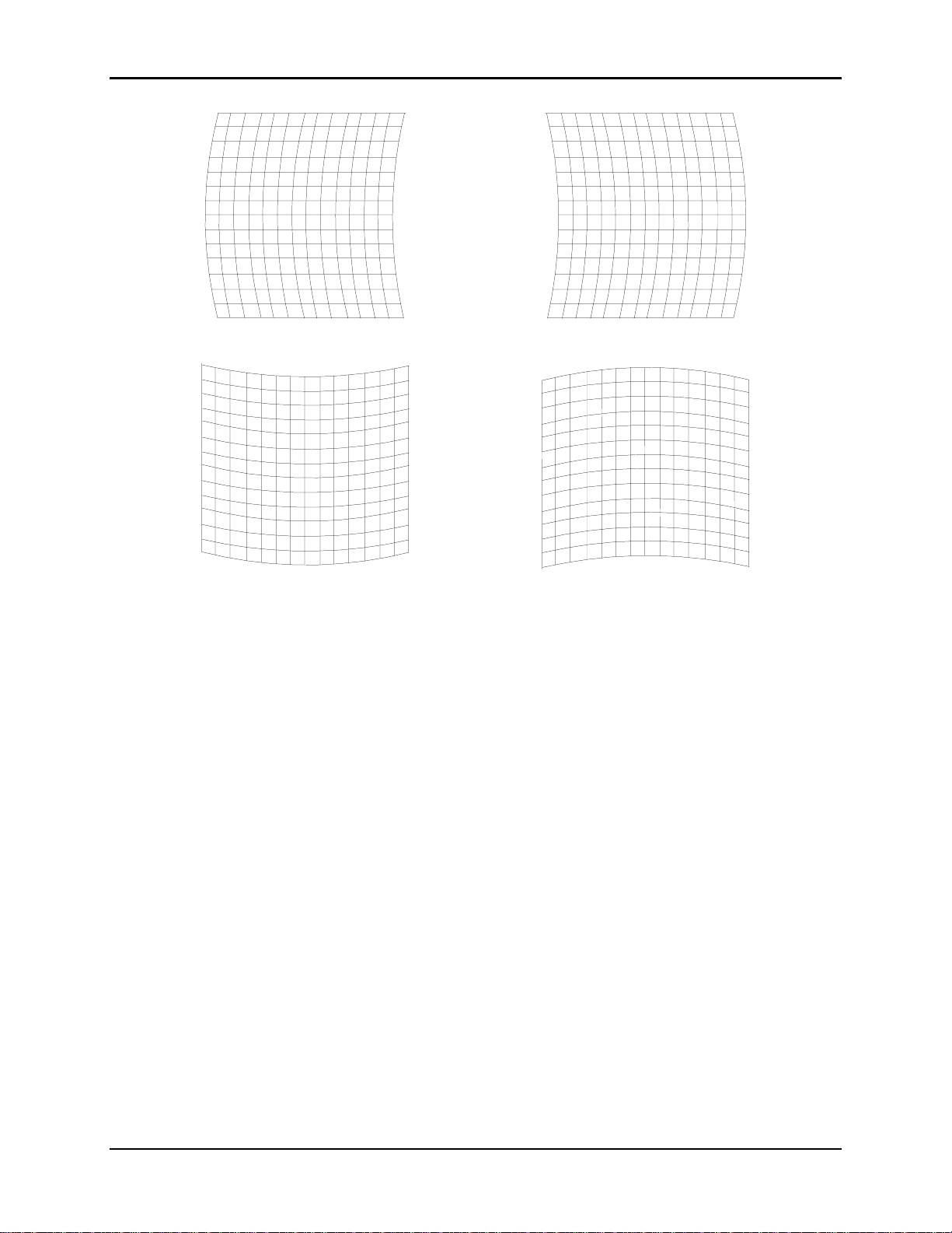
Chapter 4—Setup Adjustments
Horizontal bowing (vertical centerline off) . Use left/right arrow keys to cor rect.
Vertical bowing (horizontal centerline off). Use up/down arrow keys to correct.
Figure 4.0-5 Bow Distortion
4.3.4. Skew/Rotate (G)
Skew and Rotate are corrected in the same procedure using the same
screen patterns. Skew distortion “leans” horizontally lik e a trapezoidal
pattern. This means the vertical center line is skewed in one (1) direction
or another causing the entire patt er n to lean in the same direction (see
Figure 4.0-7 on page 4-15). Rotation distortion is where the entire pattern
is rotated vertically or horizontally (refer to Figure 4.0-6 on page 4-15).
Use the Standard Crosshatch test patter n (shown in Figure 4.0-4 on
page 4-13) to spot Skew or Rotation distortion. If the vertical centerline is
vertical and the horizontal centerline is horizontal, the Sk ew setting is
correct (as described in Section 4.3.7 on page 4- 18) and should not be
changed.
Perform the Rotate pr ocedure first to make the horizontal lines horizontal.
If the pattern leans left or right (as illustrated in Figure 4.0-7 on page 4-
15) proceed with the Skew procedure to correct.
4-14 Hughes-JVC Technology Corporation
Page 67
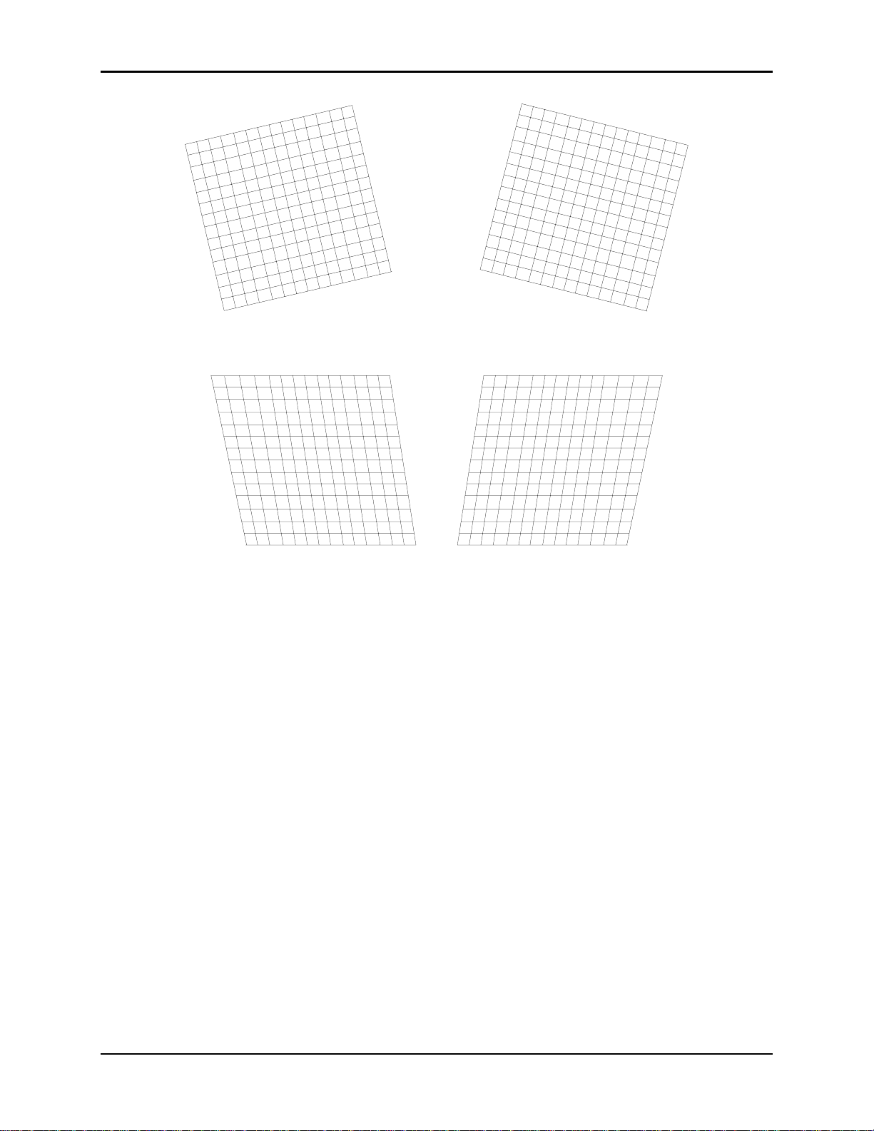
Chapter 4—Setup Adjustments
Figure 4.0-6 Vertical Rotation Distortion
Figure 4.0-7 Skew Distortion-Vertical Centerline Tilted
To correct for Rotation:
1. Select the Standard Crosshatch test patt er n.
2. Select S
KEW/ROTATE
3. Toggle the RGB
4. Use the H
IDE KEY
from the G
to select G only.
KEY
EOMETRY MENU
and hide R and B.
5. Use the up/down arrow keys to correct for vertical rot at ion.
6. Press E
SCAPE/ENTER
to exit.
To correct for Skew:
1. Select the Standard Crosshatch test patt er n.
2. Access S
KEW/ROTATE
3. Toggle the RGB
4. Use the H
IDE KEY
from the G
to select G only.
KEY
EOMETRY MENU
and hide R and B.
5. Use the left/right ar r ow keys to correct for horizontal skew.
6. Press E
SCAPE/ENTER
to exit.
.
.
HJT Model 100 User's Guide 4-15
Page 68

Chapter 4—Setup Adjustments
4.3.5. Linearity (G)
The Linearity adjustment correct s for improper horizontal or vertical grid
spacing on an image. With distorted linearity, lines in the g rid are spaced
closer together on one side and farther apart on the other (refer to Figure
4.0-8 Linearity Distortion).
To correct for Linearity Distort ion:
1. Select L
INEARITY
2. Toggle the RGB
3. Use the H
IDE KEY
from the G
to select G only.
KEY
EOMETRY MENU
and hide R and B.
.
4. Use left/right ar r ows to cor r ect horizontal linearity distortion and
up/down arrows to correct vertical linearity distortion. Make grids the
same width on the left/right side and t he sam e height at the top and
bottom.
5. Use E
DGE LINEARITY ADJUSTMENT
to perform additional linearity
correction.
6. Press E
SCAPE/ENTER
to exit.
Vertical Linearity Distortion. Use up/down arrow keys to corr ect.
Figure 4.0-8 Linearity Distortion (horizontal and vertical)
4-16 Hughes-JVC Technology Corporation
Page 69

Chapter 4—Setup Adjustments
4.3.6. Edge Linearity
Edge linearity adjustment correct s for improper grid spacing at t he
left/right edges and top/bottom of the im age for all colors (ref er to
Figure 4.0-9).
Horizontal Edge Linearity Distortion. Use left/right arrow keys to corr ect.
Vertical Edge Linearity Distortion. Use up/ down arrow keys to correct.
Figure 4.0-9 Edge Linearity Distortion (horizontal and vertical)
To correct for Edge Linearity Distortion:
1. Select E
DGE LINEARITY
from the G
EOMETRY MENU
2. Use the left/right or up/down arrow keys to correct for Edge Linearit y
distortion. Make the edge grids the sam e width as the center grids.
3. Press E
SCAPE/ENTER
to exit.
HJT Model 100 User's Guide 4-17
.
Page 70

Chapter 4—Setup Adjustments
4.3.7. Keystone
The Keystone adjustment corrects the lines closest t o t he scr een’s edg e.
This adjustment makes lines par allel to the centerline of the test patt e r n
or square to the screen edge (r efer to Figure 4.0-10).
Horizontal (side to side) Keystone Distortion. Use left/right arrow keys.
Vertical (top/bottom) Keystone Distortion. Use up/down arrow keys.
Figure 4.0-10 Keystone (horizontal and vertical)
To correct for horizontal and vertical Keystone Distortion:
1. Select K
EYSTONE
from the G
EOMETRY MENU
2. Use the left/right ar r ow keys to correct for horizontal keystone distortion.
Use the up/down arrow keys to correct for vertical k eystone dist ortion.
3. Press E
SCAPE/ENTER
to exit.
4-18 Hughes-JVC Technology Corporation
.
Page 71

4.3.8. Pincushion
The Pincushion adjustment corrects for warped distortion at the sides
or top and bottom of the im age.
Chapter 4—Setup Adjustments
Use left/right keys for distortion at top and up/down keys for dist ortion at bottom.
Figure 4.0-11 Pincushion Distortion (four views)
To correct for Pincushion Distortion:
1. Access the P
INCUSHION ADJUSTMENT
from the G
EOMETRY MENU
2. Use the left/right arrow keys to correct pincushion distortion as shown
on the top two patterns in Figure 4.0-11. Use the up/down arrow keys
to correct pincushion distortion as shown on the bottom two patterns.
3. Press E
NOTE: Some of the previous Geometry adjust m ents were performed
SCAPE/ENTER
to exit.
for Green only (Centering, Linearity, and Skew/Rotate). The next
procedures align Red and Blue to Green for those adjustments.
If Red and Blue are aligned to Gr een as closely as possible now,
convergence will be much easier to accomplish later on, resulting in a
better image.
HJT Model 100 User's Guide 4-19
.
Page 72

Chapter 4—Setup Adjustments
4.3.9. Centering (Red and Blue)
Red and blue are now centered horizontally and vertically to match green
as closely as possible.
To Center Red and Blue:
1. Use the H
IDE KEY
to unhide R. Verify that R and G are bot h on t he
screen with B hidden.
2. Access C
ENTERING
3. Toggle the RGB
from the G
to select R.
KEY
EOMETRY MENU
4. Use the arrow keys and center red to overlay the green as closely as
possible. If there is an error between the red and green lines, use the
arrow keys to adjust red. Differences between the sides or top and
bottom errors will be split. Balancing t h is er r o r m a kes it easier to
perform convergence later. St r ict ly mat ching the center may cause a
larger error on one side than the other making convergence harder.
5. Toggle the RGB
6. Use the H
IDE KEY
to select B.
KEY
to unhide B. All three (3) colors should now be on
the screen. This step can also be perfor m ed with only B and G on
screen.
7. Use the arrow keys and position the Blue lines to overlay the Green
and Red lines.
8. When f inished cent er ing Red and Blue to Green, press
E
SCAPE/ENTER
to exit the adjustment.
4.3.10. Linearity (Red and Blue)
Red and Blue Linearity is now adjusted to match Green as closely as
possible.
.
To adjust the Red and Blue Linearity:
1. Access L
2. Use the H
INEARITY
IDE KEY
from the G
EOMETRY MENU
and hide B. Be sure that R and G are both on the
.
screen with B hidden.
3. Toggle the RGB
to select R.
KEY
4. Use the arrow keys and adjust the Red Linearity to match Green as
closely as possible. If there is an error between the Red and Gr een
lines, adjust Red to split the error difference between the sides or top
and bottom.
5. Toggle the RGB
6. Use the H
IDE KEY
to select B.
KEY
and unhide B. All three (3) colors should now be on
the screen.
NOTE: This step can also be perform ed with B and G only on screen.
7. Use the arrow keys and adjust the Blue Linearity to match the Green
and Red lines. Refer to Step 4 to balance any error .
8. When finished matching the Red and Blue Linearity to Green,
press E
SCAPE/ENTER
to exit the adjustment.
4-20 Hughes-JVC Technology Corporation
Page 73

4.3.11. Skew/Rotate (Red and Blue)
Adjust Red and Blue Skew/Rotate to match G r een as follows:
Chapter 4—Setup Adjustments
1. Select S
KEW/ROTATE
from the G
EOMETRY MENU
.
2. Hide B. Verify that R and G are both on the scr een with B hidden.
3. Toggle the RGB
4. Use the up/down arrow keys and adjust R
to select R.
KEY
ED ROTATION
to match
Green as closely as possible.
5. Use the left/right ar r ow keys and adj ust R
ED SKEW
to match Green as
closely as possible.
6. Toggle the RGB
7. Use the H
IDE KEY
to select B.
KEY
and unhide B. All three colors should now be on the
screen.
NOTE: This step can also be perform ed with B and G only on screen.
8. Toggle the RGB
9. Use the up/down arrow keys and adjust B
to select B.
KEY
LUE ROTATION
to match
Green and Red as closely as possible.
10. Use the left/right arrow keys and adjust B
LUE SKEW
to match Green
and Red as closely as possible.
11. Press E
SCAPE/ENTER
12. Save changes by selecting S
In the G
EOMETRY MENU
to exit the adjustment.
AVE CHANGES NOW
, reset R
EG ENABLE
back to ON (checked box).
from the M
AIN MENU
.
4.3.12. Projection Lens Focus (Fine)
The Projection Lens must now be focused sharply to perform the
Convergence procedures properly.
To obtain a Fine Focus the Projection Lens:
1. Select S
2. Select T
3. Select F
YSTEM
EST PATTERN
OCUS
from the M
from the S
from the T
AIN MENU
EST PATTERN MENU
NOTE: H pattern is pref er r ed for focusing the Proj ect ion Lens.
4. Select P
ROJECTION LENS
from the S
5. A small window displaying Focus and Zoom arrows appears on the
screen.
6. Use the right/left arr ow keys to g et a sharp focus at the center of the
screen using green “spacer balls” to focus on.
NOTE: “Spacer Balls” are directly in f ront of the screen in the bright
areas of the image. T hey are t iny, random , irregularly shaped spots
seen throughout the image. When these spots are distinctly defined,
the projection lens is in sharp focus.
7. Press E
NOTE: The H pattern should also be in sharp f ocus. If not, the
E
LECTRONIC FOCUS
to complete this adjustment.
NTER
may need readjusting (see Section 4.4 about
.
YSTEM MENU
YSTEM MENU
.
.
.
HJT Model 100 User's Guide 4-21
Page 74

Chapter 4—Setup Adjustments
CRT Focus and H/V Dynamic Focus). This fact or y-set t ing does not
normally require readjustment. The F
P
REFERENCES MENU
may now be unchecked to prevent accidental
defocusing.
4.4. CRT Focus and H/V Dynamic Focus
The CRT and H/V Focus adjustments ar e factory-set and do not normally require
adjustment. They should be perfor m ed together in a back-and-for t h manner to
achieve the best possible overall focus.
To perform the CRT Focus:
OCUS ENABLE
box in the
1. Fr om t he F
ACTORY ADJUSTMENTS MENU
2. Select G on the remote.
3. Select t he S
TANDARD CROSSHATCH
4. Use t he up/ down arrow keys to obt ain t he best possible focus in both the
center of the screen and in the overall test pattern.
5. Repeat t he above steps for R and B.
To perform the H/V Dynamic Focus:
1. Fr om t he F
2. Cont inue with the S
ACTORY ADJUSTMENTS MENU
TANDARD CROSSHATCH
NOTE: The H/V Dynamic focus is performed on all three (3) colors together
and the colors are not individually selectable.
3. Use t he up/ down arrow keys to achieve the best possible focus at the edges
of the screen.
4. Repeat t he CRT Focusing from above, then repeat the H/V Dynamic Focus
again. Several iterations may be needed to achieve the best possible overall
screen focus.
4.5. ILA® Sensitivity and Bias
®
ILA
Sensitivity and Bias are preset for the f act ory-set sources and will not
normally require adjustment. Readjustments may be required due to variations
between the factory and the field environments. When new sources are set up,
®
Sensitivity and Bias must be set (or copied from anot her source and
ILA
touched-up) for each new source.
The ILA
start with Blue since Blue is a weaker color to observe than Red or Green. The
ILA
brightness on the screen. The ILA
to each ILA
from the CRT will cause the ILA
adjustment will put each ILA
incorrectly, the black level will be adversely affected and the ILA
not react properly to incoming lig ht . Perform all ILA
darkened room.
®
Sensitivity and Bias can be adjusted for any color. It is preferable to
®
Sensitivity is the ILA® biasing frequency that af fects the resolution and
®
assembly to a “just off” threshold point. The smallest incoming light
, select CRT F
OCUS
.
test pattern.
, select H/V D
YNAMIC FOCUS
test pattern from above.
®
bias settings adjust the electrical bias levels
®
assembly to react. When properly set, this
®
assembly at the threshold of operation. If set
®
Bias adjustments in a
®
assembly will
.
4-22 Hughes-JVC Technology Corporation
Page 75

To set the ILA® Sensitivity:
Chapter 4—Setup Adjustments
1. Under t he S
YSTEM-PREFERENCES MENU
, verify that the S
HUTTERS ON HIDE
box is checked.
2. Use t he H
IDE KEY
3. Toggle the RGB
4. Access ILA
5. Use t he up/ down arrow keys to select an ILA
and hide Red and Green.
to highlight Blue.
KEY
®
S
ENSITIVITY ADJUST
from the M
AINTENANCE MENU
®
Sensitivity of 11 as indicated
.
in the screen window. This is the default setting and should be acceptable
for general viewing. A lower number may be preferred for HDTV. A higher
setting results in higher brightness but greater image lag and possibly lower
resolution. The ILA
®
Sensitivity setting depends on the type of viewing
environment. Some trial and error may be needed to get the exact setting for
each environment.
6. Press E
SCAPE
NOTE: Computer graphics req uire high resolution but typically are not fast
moving—the ILA
Video sources are typically lower resolution but have more movement—the
®
ILA
Sensitivity is set in the range of 8 - 11.
CAUTION!!!
when the setting is complete.
®
Sensitivity will typically by set in the range of 11 - 15.
Changing ILA® Sensitivity requires re-
checking and re-adjusting, if necessary, sensitivity offset, t hr eshold
offset, and shading.
®
To set the ILA
1. Use t he sam e color from the ILA
Bias:
®
Sensitivity adjustment
and with the same two (2) colors hidden.
2. Uncheck S
3. Access ILA
Use the up/down arrow keys to decrease the ILA® Bias so the brightest area
of the ILA
®
ILA
image just begins to appear on the scr een.
HUTTERS ON HIDE
®
B
IAS ADJUST
®
image just extinguishes. Then incr ease the bias level until the
. Hide the selected color.
from the M
AINTENANCE MENU
.
NOTE: It is crucial to set the bias level so the selected color just begins to
appear on the screen. Find the spot on the screen where the selected color
first begins to get br ighter and use that as the reference point . Adjust the
bias level above and below this point to find the setting where one (1) click
causes an increase in brightness and stop at that point. This insures that the
weakest signal will cause the ILA® assembly to respond properly.
Repeat the above ILA
®
Sensitivity and ILA® Bias procedures for the remaining
two (2) colors. Save the changes.
HJT Model 100 User's Guide 4-23
Page 76

Chapter 4—Setup Adjustments
4.6. Convergence (XY Registration)
Convergence (XY Registration) overlays the CRT beams onto each other.
XY Registration procedures are required to align the Red, Blue, and Green CRT
beams together on the screen.
NOTE: For a better understanding of what is being accomplished, take the tim e
now to read the entire Convergence (XY Registr at ion) sect ion before making any
adjustments.
4.6.1. Purpose of Convergence
The XY Convergence adjustments are used t o converg e or overlay the
Red, Green and Blue CRT images over the entir e screen area. The HJT
Model 100 Projector handles many different sources and convergence is
tied directly to a video source. One (1) channel can contain up to 20
different sources with different formats. Each of these sources must have
its own set of convergence data.
4.6.2. Cursor Shapes and Sizes
Three (3) diff er ent cur s or m odes ( as described in Table 4.0-3) are used
to make adjustments.
Table 4.0-3 Cursor Modes
Cursor Mode Description
Move
Size
Adjust
Various cursor sizes are available to adjust areas. Some areas may
require odd shaped cursors. If a long thin area appears out of
convergence, use a long thin cursor shaped like t he area. Use the cursor
size that best fits the area. Some ar eas m ay be satisfactory and will not
need any convergence corrections.
The greatest convergence correct ions ar e m ade at the center of the
cursor—avoid making corrections at the edg es of the cursor. Move the
center of the cursor over the area t hat needs cor recting. A cursor with a
long centerline is affected equally all along its centerline by the
adjustments.
Moves the cursor around the screen.
Increases or decreases the cursor size.
Makes the actual convergence adjustments.
4-24 Hughes-JVC Technology Corporation
Page 77

4.6.3. Convergence Profiled
Start with a full-size cursor when the entire screen needs adjusting.
To converge (XY Registration):
1. Start with the center of the cursor at the upper left corner.
Note that cursor is off the screen at the top and left (see Figure 4.012 on page 4-26).
2. Make corrections to the area and then, move the center of the cursor
to the numbered areas shown in Figure 4.0-12 in the seq uence
shown.
3. Size down to a ¼ screen cursor size. Move down and across the
screen in the sequence shown in Figure 4.0-13—in most cases it will
not be necessary to use a cursor smaller than the one shown.
4. If there are still some smaller areas that need convergence,
size down to a cursor that encloses about nine (9) of the rect angles.
Use the same general pattern as with the previous cursors.
Before beginning adjust m ents, experiment with the different cursors in
or M
S
IZE
OVE MODES
.
Chapter 4—Setup Adjustments
CAUTION!!!
If the A
DJUST MODE
cursor is displayed
(illustrated in Figure 4.0-14 on page 4-27), pressing the arrow keys will
alter the convergence settings. Experiment with the ar r ow keys only when
in the M
OVE
or S
IZE MODES
, not while in the A
DJUST MODE
.
To adjust by Size or Move Convergence:
1. Access Registration from the Converg ence m enu.
2. Press Mode to change cursor type.
3. Use the arrow keys to see the various cursor sizes in Size mode.
4. Use the arrow keys to move the cursor around the screen In Move
mode.
HJT Model 100 User's Guide 4-25
Page 78

Chapter 4—Setup Adjustments
Start with the full screen cursor
center at Point 1 and make
corrections.
Then move center of cursor down to
Point 2 and make corrections.
Continue placing center of cursor t o
points numbered over entire screen
(top line of the current curs or should
be at the same point as the bottom
line of the previous cursor).
When as much as possible has been
done with the full screen cursor,
change to the ¼ screen cursor in
Figure 4.0-13 below.
Figure 4.0-12 Full-Screen Cursor
Center at Upper Left (Point 1)
Figure 4.0-13 ¼ Screen Cursor
Center at Upper Left (Point 1)
Start converging with the ¼
screen cursor at the upper
left corner.
Then move the center of the
cursor through the points in
the sequence shown in the
same manner and adjust in
the same manner as the full
screen cursor.
4-26 Hughes-JVC Technology Corporation
Page 79

Chapter 4—Setup Adjustments
o
o
Move Mode
M
OVE MODE
the center.
Use the up/down and right/left keys t
move the cursor to the area of the
screen that needs convergence.
When the curs or is in t he area
desired, press M
cursor to the S
with the arrow pattern in
to change the
ODE
mode below.
IZE
Size Mode
S
IZE MODE
edges.
with the arrows at the
Use the left/right and up/ down
arrow keys to adjust the cursor t
the size needed.
Adjust Mode
The area to be adjusted is
enclosed in a rectangular border.
Areas outside the rectangle are
not affected. T he ar ea m ost
affected is the center of the
rectangle.
Do not try to make large
adjustments at the edges of the
rectangle.
Move the cursor so that the
center is over the area to be
corrected.
Figure 4.0-14 Three (3) Cursor Modes
HJT Model 100 User's Guide 4-27
Page 80

Chapter 4—Setup Adjustments
To adjust XY Registration:
1. Access the G
EOMETRY MENU
2. Ver ify that the R
EG ENABLE
.
box is checked. This toggle is norm ally ON
and is toggled to OFFonly for m aint enance.
3. Use t he RGB
TOGGLE
and the H
IDE KEY
to hide Red and Blue.
4. I f Green geometry is good, unhide Red and Blue.
OR if Green geometry is q uest ionable, recheck it now.
a. Use the St andar d Crosshatch test pattern to verify.
b. If geometry is not satisfactory, make touch-up corrections.
c. Green geometry must be correct before pr oceeding because Green is
used as a reference to converge Red and Blue.
d. If necessary, repeat any timing or geometry adjust m ent s from Section 4.2
on page 4-9 and Section 4.3 on page 4-11
5. Access the T
EST PATTERN MENU
and select RGB X-hatch. This test pattern is
a series of Red, Green, and Blue bars that form small rectangles on the
screen. The rectangles in Figur e 4. 0- 15 show a Correct ly Converged RGB
Pattern and Figure 4.0-16 illust r ates Incorrectly Converged RGB Patterns
(two examples). If this is a black and white illustr at ion, Red is shown as
white, Green as shaded, and Blue as black.
6. Access the C
ONVERGENCE MENU
and select R
EGISTRATION
. The convergence
screen will display one of the cursor modes shown in Figure 4.0-14.
7. Use S
IZE MODE
S
IZE MODE
M
OVE/SIZE MODE
8. Use t he S
first. If the M
. If the A
then, if necessary, press M
IZE MODE
OVE MODE
DJUST MODE
displays, press E
to increase the cursor size to a full screen cursor .
displays, press M
to toggle to the
NTER
to toggle to the S
ODE
to toggle to the
ODE
IZE MODE
To view a full screen cursor:
a. Move the cursor to the center of the screen.
b. Toggle the M
c. Use the arrow keys to place the cursor at the center of the scr een, then
toggle the M
d. Continue t o size the cur s or t o a full screen.
ODE KEY
ODE KEY
to the M
OVE CURSOR
to return to the S
.
IZE MODE
.
.
Blue
Red
Green
Figure 4.0-15 Correctly Converged RGB Pattern
4-28 Hughes-JVC Technology Corporation
Page 81

Chapter 4—Setup Adjustments
Red is not correctly converged in horizontal direction. Use rig ht / left arrows.
Blue
Red
Green
Blue
Red
Green
Blue not correctly converged in vertical direction. Use up/down arrows.
Figure 4.0-16 Incorrectly Converged RGB Patterns (two examples)
9. Toggle the M
ODE KEY
10. Use the arrow keys to move the center of the cursor to t he upper left
position (see Figure 4.0-12 on page 4- 26) .
11. Det er m ine if the area needs horizontal or vertical convergence using the
illustrations in Figure 4.0-15 and Figur e 4. 0- 16.
12. If converging is needed, press E
NOTE: XY convergence can be performed with all thr ee ( 3) color s on t he
screen or with Red or Blue hidden and converging one color at a time to
Green. (either method can be used). Ver ify convergence over the entire
screen area with all three colors showing.
13. Toggle the RGB
14. While observing the test patt er n, use the up/down arrow keys to converge
vertically and the left/right ar row keys to converge horizontally (refer to
Figure 4.0-15 and Figure 4.0-16) . Note that the area most affected is the
center of the cursor—avoid corrections near t he edges of the cursor. Move
the cursor center over the area where corrections are needed.
to the M
to the color that needs to be converged.
KEY
OVE MODE
NTER
with the cursor at full screen.
to go into the A
DJUSTMENT MODE
.
HJT Model 100 User's Guide 4-29
Page 82

Chapter 4—Setup Adjustments
15. When the upper left cor ner is converged satisfactorily, press E
to the M
OVE/SIZE MODE
.Toggle the M
ODE KEY
Figure 4.0-12 on page 4-26 and center t he cursor over each of the positions
in the sequence shown, wherever convergence is required, repeating the
M
OVE/SIZE/ADJUSTMENT
steps for each area that needs convergence.
16. When finished using full screen cursor, press E
KEY
to the S
IZE MODE
.
17. Use the arrow keys to size down to a cursor of approximately ¼ screen size.
18. Select the areas to be converged and converge the entire screen in the
sequence shown in Figure 4.0-13 on page 4-26. Star t at the upper left
corner and continue in the same manner as perf ormed with the full screen
cursor in Step 15.
19. Save changes when finished with XY Reg istration.
4.7. Black Level (G2) and Sensitivity Offset
G2 sets the threshold of t he CRT image and is adjusted, along with the Sensitivity
Offset adjustment, using the Grey/Pluge test pattern. Together, these
adjustments determine the level of t he dar kest and brightest areas of the video
image.
The G2 adjustment is preset at the factory and may need little or no adjustment.
These adjustments are made in sequence, one (1) color at a time. It is preferable
to start with Blue because it is the weakest color of t he t hree (3) to observe.
When the Blue settings are complete, the same adjustment s ar e per formed for
Green and Red.
to the M
and toggle the M
NTER
OVE MODE
to return
NTER
. Refer to
ODE
4.7.1. Black Level (G2)
To set the Black Level for Blue:
1. Use the RGB and H
S
HUTTERS ON HIDE
IDE KEYS
box under the S
checked.
2. Toggle the RGB
CAUTION!!!
to select B only.
KEY
Ensure that only the color to be adjusted is
highlighted. Otherwise all colors are r eset and good data from a previous
setup will be deleted.
3. Access C
ONVERGENCE MENU
4. Access the Grey/Pluge test pattern.
5. Access B
LACK LEVEL
(G2), from the C
6. Use the up/down arrow keys to adjust the black level so the small,
black square in the center of the larger black square is just barely
visible (as illustrated in Figure 4.0-17). Pr ess E
to hide R and G. Verify that the
YSTEMS-PREFERENCES MENU
and select R
ONVERGENCE MENU
ESET
.
when finished.
NTER
.
is
4-30 Hughes-JVC Technology Corporation
Page 83

Figure 4.0-17 Grey/Pluge Test Pattern
4.7.2. Sensitivity Offset
To adjust the Sensitivity Offset for Blue:
Chapter 4—Setup Adjustments
1. Access S
ENSITIVITY OFFSET
should still be the only color on the screen with the Grey/Pluge test
pattern still selected).
2. A screen will appear with a Sensitivity window. The window shows
that Red and Green are hidden (greyed out) and Blue is t he active
color to be adjusted (repeat Steps 1 and 2 from Section 4.7.1 if Blue
is not active).
3. The window shows arrow keys to adjust Sensitivity Offset. Data
numbers for minimum and maximum values are also displayed.
NOTE: Sensitivity Offs et sets the brightest level for the overall scr een
image.
4. Use the up/down arrow keys to adjust the Sensitivity Offset so the
small, white square is just barely visible inside the larger white sq uar e
(refer to Figure 4.0-17).
5. Press E
when finished.
NTER
4.7.3. Threshold Offset
To adjust Threshold Offset for Blue:
1. Access
with Blue only selected and the Grey/Pluge test pattern. Red and
Green should stil be hidden and the S
still be checked.
NOTE: Threshold Offset sets the darkest level for the overall screen
image.
2. Use the up/down arrow keys to adjust Threshold Of fset so the small,
black square is just barely visible inside the large, black square in the
same manner as in the Black Level (G2) adjust m ent in Section 4.7.1
on page 4-30.
THRESHOLD OFFSET
from the C
from the C
ONVERGENCE MENU
ONVERGENCE MENU
HUTTERS ON HIDE
(Blue
. Continue
box should
HJT Model 100 User's Guide 4-31
Page 84

Chapter 4—Setup Adjustments
NOTE: Threshold Offset can be viewed as the fine adjustment for
Black Level (G2).
3. Repeat the Sensitivity and Threshold Offset adjustments to obtain a
Grey/Pluge pattern where the small, black and small, white square
are just barely visible inside their larger squares.
Repeat the above Black Level, Sensitivity Offset and Threshold Offset
adjustments for Green and Red.
4.8. Uniformity (Shading)
Uniformity adjustments corr ect inconsist encies and brightness differences in the
CRT and ILA
®
assemblies.
4.8.1. Sensitivity Uniformity
Sensitivity sets the brightness at high ( white) video levels. Performed
one color at a time, this adjustment gets a flat, uniform br ightness in the
white areas.
To adjust the Sensitivity for Blue:
1. Darken the room as much as possible.
2. Use the RGB and H
S
HUTTERS ON HIDE
IDE KEYS
box under the S
checked.
3. Toggle the RGB
4. Access V
ARIABLE FLAT
to select B only.
KEY
5. Use the arrow keys and select a Flat Field level of about 160.
6. Access the
CONVERGENCE MENU
Sensitivity cursor and a window are displayed. The sensitivity level’s
data value for the entire screen is displayed—this value is the reset
value of 128 plus or minus the amount of offset from the previous
adjustment.
7. Observe the center of the Flat Field screen. This is the brightest area
of the screen—it is used as a refer ence t o m atch the rest of the
screen. Avoid overlapping this reference area with the cursor when
adjusting or the refer ence brightness level could change.
8. Select a 12 X 12 cursor as shown in the cursor size window.
9. Toggle the M
ODE KEY
to the M
area of the screen that is not as bright as the reference area
observed in Step 7.
10. Press E
to display the A
NTER
11. Use the arrow keys to bring the darker areas of the screen up t o
match the reference area. Avoid making adjustments at the edges of
the cursor. Move the center of the cursor over the area that needs to
be adjusted.
12. Obtain the best possible uniformity over the entire screen, then repeat
Steps 9 - 11 with an 8 X 8 cursor.
to hide R and G. Verify that the
YSTEMS-PREFERENCES MENU
from the T
EST PATTERN MENU
and select S
OVE CURSOR
DJUSTMENT CURSOR
ENSITIVITY
. Move the cursor to an
is
.
. The
.
4-32 Hughes-JVC Technology Corporation
Page 85

13. Select a 4 X4 cursor and repeat Steps 9 - 11 again for this cur sor,
reducing the cursor size to adjust smaller ar eas, if necessary.
14. Press E
to complete this adjustment.
NTER
4.8.2. Threshold Uniformity
Threshold sets the brightness at low (black ) video levels to achieve a flat,
uniform brightness in the black areas. Perform adjustm ents one (1) color
at a time.
To adjust the Threshold for Blue:
1. Darken the room as much as possible.
2. Use the RGB and H
S
HUTTERS ON HIDE
checked.
3. Toggle the RGB
4. Access V
ARIABLE FLAT
5. Use the right/left ar r o w keys and select a Flat Field level of about 50.
6. Access the C
The Threshold cursor and window appear on the screen showing the
reset value of 128.
7. Use the same reference area from the Sensitivity Uniformity
adjustment as the refer ence ar ea for the Threshold Uniform it y
adjustment. Avoid overlapping this ref er ence area with the cursor
when adjusting or the reference brightness level could change.
8. Select a 12 X 12 cursor (as shown in the Cursor Size window).
9. Use the M
OVE CURSOR
that is darker than the reference area observed in Step 7.
10. Press E
NTER
11. Use the arrow keys to bring the darker areas of the screen up t o
match the reference area.
NOTE:The area most affected is at the center of the cursor—avoid
making adjustments at t he edges of the cursor. Move the center of
the cursor over the area that needs to be adjusted.
12. Obtain the best possible uniformity over the entire screen, then repeat
Steps 9 - 11 with an 8 X 8 cursor.
13. When Step 12 is complete, select a 4 X4 cursor and repeat
Steps 9 - 11 again for this curs or , reducing the cursor size again to
adjust smaller areas, if necessar y.
14. Press E
NTER
box under the S
KEY
ONVERGENCE MENU
to display the A
to complete this adjustment. Save all changes.
Chapter 4—Setup Adjustments
IDE KEYS
to hide R and G. Verify that the
YSTEMS-PREFERENCES MENU
to select B only.
from the T
EST PATTERN MENU
and select T
HRESHOLD
.
.
to move the cursor to an area of the screen
DJUSTMENT CURSOR
.
is
Sensitivity and threshold may need readjusting for good Blue uniformity.
Repeat the above Sensitivity and Threshold Uniformity adjustments for
Green and Red. Select one (1) color at a time when resetting to avoid
losing valid data from a previously adjusted color.
HJT Model 100 User's Guide 4-33
Page 86

Chapter 4—Setup Adjustments
4.8.3. Color Balance (Grey Scale)
Color balancing sets the color balance over the entire screen. This adjustment
may be necessary after performing Threshold and Sensitivity procedures. The
Grey Scale test pattern should be grey throug hout t he entire screen area with a
normal, gradual bright ness t r ansition from bar to bar (no perceived colorat ion).
If the test pattern is not grey throughout, color balancing is necessary.
Threshold and Sensitivity Offset s can be m ade for the entire screen to get pr oper
color balance for the bright and dark areas.
To check for proper Color Balance (Grey Scale):
1. Access G
REY SCALE
2. Toggle the RGB
from the T
and verify all colors are selected and on screen.
KEY
EST PATTERN MENU
.
3. Observe the two or three darkest bars in each of the four (4) sections
of the test pattern. I f any color is too prominent in these two or three
bars, adjust the Threshold Offset (see instructions following for
adjusting the Threshold Offset) for that color .
4. Observe the two or three brightest bars in each of t he four (4)
sections of the test pattern (refer to Figure 4.0-17 on page 4-31).
If any color is too prominent in these two (2) or t hr ee (3) bars, adjust
the Sensitivity Offset ( see inst ructions following for adjusting the
Sensitivity Offset) for that color.
NOTE: A color may appear too weak, due to the other t wo (2) color s
being too dominant. If so, slightly increase sensitivity offset f or the
weak color.
To adjust the Sensitivity Offset for the best Color Balance:
1. Toggle the RGB
and select the color that is too prominent in t he
KEY
brightest bars .
2. Access S
ENSITIVITY OFFSET
from the C
ONVERGENCE MENU
.
3. Use the up/down arrow keys to increase or decrease the Sensitivity
Offset slig ht ly so that t he brightest bars in the test patter n ar e without
color, i.e. grey. Make a note of t he offset data number before making
any adjustments in case an error is made and the original setting is
needed. Recheck the test pattern for a normal, gradual transition from
bar to bar. If increasing the Offset, avoid overadjusting any of the
colors. Leave a normal, gradual brightness transition between the
two (2) brightest bars.
NOTE: The two (2) numbers that appear in the box on the scr een
represent the lowest and highest Sensitivity settings on the scr een. If
either of these settings is at t he minimum (0) or maximum (255) there
will be no adjustment range available to adjust the Offset. This means
that one (1) area on the screen has been adjusted t oo high or too low
during the Sensitivity adjustment and is rest r ict ing the Offset
adjustment.
Before the Offset can be adjusted, this area must be increased or
decreased to allow for more range to per form the Off set adjustment.
4-34 Hughes-JVC Technology Corporation
Page 87

Chapter 4—Setup Adjustments
Recheck the Sensitivity adjustment to locate t his specific area, if
possible, and increase or decrease its level accordingly. If t his is not
possible, the Shading procedure may have to be repeated.
4. If necessary, recheck and readjust t hr eshold color balance.
To adjust the Threshold Offset for t he best color balance:
1. Toggle the RGB
and select the color that is too prominent in t he
KEY
dark bars .
2. Access T
HRESHOLD OFFSET
from the C
ONVERGENCE MENU
.
3. Use the up/down arrow keys to slightly increase or decrease the
Threshold Offset so t he darkest bars in the test pattern are without
color, i.e. grey. Make a note of the offset setting before making any
adjustments in case an error is made and original setting is needed.
Recheck the test pattern for a normal, gradual transit ion from bar to
bar. If increasing the Offset, avoid overadjusting any of t he color s .
Leave a normal, gradual brightness tr ansition between the two
brightest bars.
NOTE: The two (2) numbers that appear in the box on the scr een
represent the lowest and highest Threshold settings on the screen. If
either of these settings is at t he minimum (0) or maximum (255) there
will be no adjustment range available to adjust the Offset. This means
that one (1) area on the screen has been adjusted t oo high or too low
during the Threshold adjustment and is r estricting the Off set
adjustment.
Before the Offset can be adjusted, this area must be increased or
decreased to allow for more range to per form the Off set adjustment.
Recheck the Threshold adjustment to locate this specific area, if
possible, and increase or decrease its level accordingly. If t his is not
possible, the Color Balance procedure may have to be repeated.
4. If necessary, recheck and readj ust the Sensitivity Color Balance.
4.9. Picture Settings
Picture settings affect the image quality. Brightness and Contrast can be
adjusted for any type of source. Color Tint, and Sharpness are only active with
non RGB-type VICs. Complete color balancing before adjusting these setting s.
HJT Model 100 User's Guide 4-35
Page 88

Chapter 4—Setup Adjustments
Figure 4.0-18 Cont/Bright Test Pattern
The nine (9) black and white squares overlay the image on t he scr een.
4.9.1. Brightness
To adjust Brightness:
1. Display external image.
2. Access the Cont/Bright test pattern from the T
3. Access B
RIGHTNESS
from the P
ICTURE MENU
EST PATTERN MENU
.
4. Use the up/down arrow keys to increase or decrease the B
setting so the blackest part of the image is equal to the black squares
in Figure 4.0-18.
5. Press E
SCAPE
to leave the B
RIGHTNESS
adjustment.
4.9.2. Contrast
To adjust Contrast:
1. Using external image and Cont/Bright test Pattern from pr evious step,
access C
ONTRAST
from the P
ICTURE MENU
2. Use the up/down arrow keys to increase or decrease the C
setting so the whitest part of the image is equal to the white squares
in Figure 4.0-18.
NOTE: Contrast can be adjusted for individual colors as well as all
colors combined.To adjust only one (1) color, toggle the RGB
the color desired. Hide the other two (2) colors, and use the left/right
arrow keys to adjust. Access Test Pattern 1 (O
Cont/Bright overlay pattern.
.
) to remove the
FF
.
RIGHTNESS
ONTRAST
to
KEY
4-36 Hughes-JVC Technology Corporation
Page 89

4.9.3. Color, Tint, Sharpness
The Color, Tint, and Sharpness sett ings are only active with non-RGB
type VICs. Begin each adjustment by displaying external imag e.
To adjust Tint:
Chapter 4—Setup Adjustments
1. Access T
INT
2. Use the up/down arrow keys to set the desired Tint level.
To adjust Color:
1. Access C
OLOR
2. Use the up/down arrow keys to set the desired Color level.
To adjust Sharpness:
1. Access S
HARPNESS
2. Use the up/down arrow keys to set the desired Sharpness level.
4.9.4. Black Enhance
The Black Enhance feature increases the low level detail in the dark
areas of the image. Adj ust the Black Enhance if the dark areas of the
image still do not show enough detail afte r com pleting the other picture
settings.
To adjust Black Enhance:
1. Select B
2. Press E
3. Select the setting that provides the best det ail in the dark areas.
LACK ENHANCE
NTER
from the P
from the P
from the P
to toggle.
ICTURE MENU
ICTURE MENU
ICTURE MENU
from the P
.
.
.
ICTURE MENU
.
4.9.5. VIC Settings
To select specific VIC Option Settings when sett ing up a new channel:
1. Access VIC S
ETTINGS
from the P
ICTURE MENU
allow the operator to select specific VIC option set t ings when setting
up new channel.
2. Press escape if the projector uses only one VIC. If the projector has
more than one VIC option, ref er to Section 4.11 on page 4-39 for
details on how to set up for optional VICs.
3. VNR (V
IDEO NOISE REDUCTION
) is available in the submenu. This
option reduces noise in the image but also reduces detail because it
narrows the video bandwidth. Use trial and error to determine if this
VNR option is appropriate for the im age being viewed.
HJT Model 100 User's Guide 4-37
. A submenu appears to
Page 90

Chapter 4—Setup Adjustments
4.10. Backing up Settings
The source file parameters pr eviously set up (and any other source files attached
to one channel) can be copied to another channel. Copy parameters if the source
has the same basic parameters but different picture settings. A channel can be
set up for a source with picture settings specific to that source, then copied to
another channel. The channel receiving the copied inf or m ation can have the
picture settings adjusted for the image that will be received on that channel—two
(2) channels are now set up for the same type of sour ce but with dif ferent picture
settings. This function saves time and also backs up the settings from the or iginal
channel. When copying from one (1) channel to another channel, verif y that both
channels use the same type of VIC. This can be deter m ined by accessing t he
S
YSTEM-MAINTENANCE MENU
types.
To Copy Settings from one channel to another channel:
and selecting S
TATUS LIST
, which shows the VIC
1. Access the C
HANNELS MENU
and highlight the channel that is to be copied
(highlight by pressing the number or scroll with arrow).
2. Press M
3. Select C
on the remote.
ODE
from the submenu. This copies t he channels ’ name, VIC path,
OPY
and attached sources into a Paste Buff er .
4. Highlight the channel to P
CAUTION!!!
ASTE TO
; press M
Verify that the channel copied to is blank.
ODE
, select P
ASTE
.
5. I f all of the sources that were copied fr om t h e first channel are not needed in
the second channel, they can be detached from the second channel.
Change to the S
OURCE LIST
arrow keys, then deselect by pressing E
, then select the unwanted sources with the
to detach them from the
NTER
channel.
6. These “copied” channels can be adjusted for Pict ur e and Timing to match
any incoming source for the new channel without affect ing the original
source from the fir st channel. Gemometry, Conversion, and ILA
®
Setting are
“shared” by the Source File.
NOTE: For convenience store a list of all available sources in one specific
channel. This can be used as a source “master” list. For example, have all
available sources attached to Channel 99. Use this as a master list from
which any source can be attached at any time. Having all available sources
in one “master” channel avoids having to remember where any specific
source is located and the time involved in hunting through various channels
to find a particular source.
4-38 Hughes-JVC Technology Corporation
Page 91

4.11. Video Input Cards
Table 4.0-4 lists the five (5) t ypes of optional Video Input Cards (VICs) available for use
with the HJT Model 100 projector.
Table 4.0-4 VIC Types
VIC Name Description
Wide Bandwidth
RGBHV
Graphics Enhancer
RGBHV
Quad RGBHV
Video Mux
(multi-port)
Component HDTV
(YP
bPr
) Input
Module
Quad Standard
Decoder Module
(with Line
Doubler)
Optional The HJT Model 100 Projector includes one (1) intr egrated
RGBHV (VIC 1.1). A second option RGBHV VI C may be
used in place of an external switcher. Used with standard
RGBHV inputs such as VGA, SVGA, and Line-Doubled
Video.
Optional Same as Wide Bandwidth VIC except for enhanced graphics
capabilities. Used with standard RGBHV inputs such as VGA,
SVGA, and Line-Doubled Video.
Optional Same type as the above RGBHV except for having four ( 4)
separate RGBHV input ports allowing for m ore source
connections.
Optional
One input mode is used for High Definition Television (YP
inputs.
The other input can be used for RGB (sync on green) signals.
Optional Supports NTSC 3.88, PAL, SECAM, and NTSC 4. 43 sour ces.
One input is for S-Video with separate Y/C com ponent s.
The other input is for Com posit e Video.
The decoder mode is selectable through VI C SETTINGS in the
Channels menu (see VIC Settings on page 4-37).
Chapter 4—Setup Adjustments
bPr
)
Illustrations of VIC input panels and connections ar e shown in Figur es 4- 18 ( view
of right side of projector) and 4-19 to 4-22 (VIC connections and indicators) at t he
end of this section.
Prior to using a VIC, the following steps must be completed:
1. Install the VIC into the slot to the right of the standard RG BHV inputs on the
right side (facing the rear) projector.
2. Connect the source input cables from a compatible source.
3. Edit the VIC for use in a designated channel.
4. Select the proper input under VIC S
ETTINGS
(this step is necessary for Quad
Standard Decoder Module VICs only).
HJT Model 100 User's Guide 4-39
Page 92

Chapter 4—Setup Adjustments
4.11.1. Installing (or Removing) a VIC
To install a VIC:
1. Turn projector power off with the remote.
2. Remove the two (2) screws and panel covering the optional VIC slot
(see Figure 4.0-19). Slide t he VIC into the VIC slot to the right of the
standard RGBHV inputs. Retain the screws removed fr om the panel
to install the VIC.
NOTE: Two (2) panels must be removed to inst all a Q uad RGBHV
Video Mux (multi-port) VIC or a Quad Standard Decoder Module
(with Line Doubler) VIC.
3. Tighten the two (2) screws (four [4] scr ews on the Quad RG BHV
Video Mux [multi-port] VIC or the Quad Standard Decoder [with
Line Doubler] VIC) on the left and right side of the VIC
(see Figure 4.0-19 ).
REMOTE IR IN
R G B H/CS V
RGBHV Video Input
Figure 4.0-19 Projector RGBHV Inputs with Optional Component
HDTV (YPbPr) Input Module VIC Installed
To remove a VIC:
1. Turn projector power off with the remote.
2. Disconnect all input connectors and label them, if necessary.
3. Loosen the two (2) holding screws on the left and right sides of the
VIC (Table 4.0-5 lists specif ic reference Figures for each VI C) screws
must be completely loose to remove the VIC.
4. Grasp the VIC connector brack et and pull the VIC out (wiggle the VIC
a little, if necessary, to extract it).
4-40 Hughes-JVC Technology Corporation
Page 93

4.11.2. Connecting VIC Source Cables
Connect the source cables to the input connectors as mar ked on the rear
of the VIC.
Table 4.0-5 VIC Video Source Cable Connections
VIC Input
Connectors
Wide Bandwidth
RGBHV
Graphics Enhancer
RGBHV
Quad RGBHV Video
Mux (multi-port)
Component HDTV
(YP
bPr
) Input
Module
Quad Standard
Decoder Module
(with Line Doubler)
Connect the RGBHV cables to the appropriately marked input jacks
(Figure 4.0-20 on page 4-44).
Connect the RGBHV cables to the appropriately marked input jacks
(Figure 4.0-20 on page 4-44).
Connect the RGBHV cables to the input connectors on t he por t(s) to be used
(Figure 4.0-21on page 4-44).
Connect the three (3) input cables to the appr opr iate input jacks
(Figure 4.0-22 on page 4-44).
NOTE: Red, Green, and Blue input jack s ar e in a different order f r om the
RGBHV VIC with Green at the left , Blue in the middle, and Red on the right.
The HDTV YP
VIC uses the same circuitry and input jacks t o pr ocess
bPr
two (2) different t ype of inputs; the GBR input and the YP
Only one (1) of these inputs may be selected at any one time.
The selection of one of these input s is m ade by editing the second number in
the VIC column (see editing VICs following) and using separate channels
for their sources.
There are two (2) distinct input connections (Fig ure 4.0-23 on page 4-45).
The input connector at right , labeled Video is for Composite Video (C-VID).
The two (2) connectors at left, labeled Y and C are for S-Video.
The selection of one of these input s is m ade by editing the second number in
the VIC column (see editing VICs, below) and using separ ate channels for
their sources.
Chapter 4—Setup Adjustments
Cable Connections
bPr
input.
4.11.3. VIC Editing
The VIC column in the C
HANNELS MENU
sources coming into the projector follow the correct path through the
correct VIC input.
To edit a VIC:
1. Select C
HANNELS
from the M
AIN MENU
2. Select a blank channel.
NOTE: If there are no blank channels, don't edit an existing channel
for a new VIC—press M
and cut the entire channel entry and start
ODE
from a blank channel.
3. Press the M
4. Select E
DIT
ODE KEY
.
to display the E
5. Press the right arrow to move to the VIC colum n, then press E
HJT Model 100 User's Guide 4-41
must now be edited so the
.
submenu.
DIT
NTER
.
Page 94

Chapter 4—Setup Adjustments
6. Use the up/down arrows to select the VIC number (refer to Table 4.0-
6).
Table 4.0-6 VIC Edit Numbers
Input VIC
1.1
2.1
2.1
2.1 to 2.4
2.1 or 2.2
2.1 or 2.2
Standard RGBHV
Wide Bandwidth RGBHV
Graphics Enhancer RGBHV
Quad RGBHV Video Mux (multi-port)
Component HDTV (YP
) Input Module
bPr
Quad Standard Decoder Module (with Line Doubler)
7. Press the right ar r ow again t o move to the second VIC column—use
the second column to select the VIC port # for the Quad RGBHV
Video Mux (multi-port) VIC, or t he HDTV YP
C-VID input for the Q uad St andard Decoder Module VIC.
Table 4.0-7 Optional VIC Port Numbers and LEDs
Port # VIC Input
1, 2, 3 or 4
1 or 2
1 or 2
Quad RGBHV Video Mux
(multi-port)
Component HDTV
(YP
) Input Module
bPr
Quad Standard Decoder
Module (with Line Doubler)
NOTE: When act ivating a Quad Standard Decoder Module VIC,
be sure to have a proper source connected to the inputs on the rear
panel. The projector will not select an appropriat e sour ce without a
proper input source.
8. The channel and an appropriate sour ce should now be named and
edited in the C
4-2 about Setup Preparation.
NOTE: If switchers are used with the projector, the switcher's port
number is edited in the third VIC column. Pr ess the right arrow key to
access the third column, press E
select a switcher port #.
The corresponding LED (1, 2, 3, or 4) will light
when the appropriate port is selected and the
channel and source are active.
#1 for [YPbPr] lights the corresponding LED on t he
left side of the VIC panel.
#2 for [RGB] lights t he corresponding LED on the
right side of the VIC panel.
#1 input for Y/C (S-video) lig ht s the LED on the
left side when this channel is active.
#2 input for C-VID (Composite Video) lights the
right side LED when this channel is active
(labeled "Video").
NOTE: Only one (1) of these LEDs can light
at any one (1) time.
HANNELS LIST
. This is covered in Section 4.4.1 on page
and use the up/down keys to
NTER
VIC, and the YC or
bPr
4-42 Hughes-JVC Technology Corporation
Page 95

4.11.4. VIC Settings
VIC Settings is necessary only when using a Quad Standard Decoder
Module (with Line Doubler) VIC. After editing t he VIC, the source video
mode or format must be select ed by using VIC S
P
ICTURE MENU
.
To select the source video mode or format:
1. Select the channel that has been edited for use by the Quad
Standard Decoder Module VIC.
2. From the P
3. Select Q
ICTURE MENU
UAD DECODER/DOUBLER
are listed in Table 4.0-8).
Table 4.0-8 Quad Decoder Modes
Quad Decoder Modes
, select VIC S
NTSC
PAL
SECAM
4.43 NTSC
B/W 50 Hz
B/W 60 Hz
Chapter 4—Setup Adjustments
from the
VIC
ETTINGS
ETTINGS
MODE
.
from the screen (choices
4. From the list displayed, use the ar row keys and highlight the decoder
mode desired for this channel, and then press E
NTER
to select.
5. Repeat Steps 1 - 4 to set t he decoder mode for any other channel,
being sure the other channels also have the Quad Standard Decoder
Module VIC selected. The Quad Standard Decoder Module VIC can
process only one (1) of these decoder modes per channel. A switcher,
set up for decoder modes, can be used to increase t he num ber per
channel. If not using a switcher, assig n only one (1) decoder m ode per
channel.
6. The other choice under VI C Settings is VNR (V
R
EDUCTION
)—however this feature is not commonly used. VNR is
IDEO NOISE
intended to decrease the video noise level but will also reduce the
sharpness of the image. Select VNR if the image has a significant
amount of noise, then evaluate the imag e to decide to check this box
or leave it unchecked.
HJT Model 100 User's Guide 4-43
Page 96

Chapter 4—Setup Adjustments
Figure 4.0-20 Wide Bandwidth or Graphics Enhancer RGBHV VIC
NOTE: Graphics Enhancer and Wide Bandwi dt h RGBHV VIC’s have the same inputs.
Figure 4.0-21 Quad RGBHV Video Mux (multi-port) VIC
Figure 4.0-22 Component HDTV (YPbPr) Input Module VIC
4-44 Hughes-JVC Technology Corporation
Page 97

Chapter 4—Setup Adjustments
Figure 4.0-23 Quad Standard Decoder Module (with Line Doubler) VIC
4.12. Updating Software
The projector's soft ware resides in F
projector's serial Port A. T o perform an update, a disk containing the updated
Boot Software (boot.hex) and/or System Software (ssys.hex) and a PC with
W
INDOWS
Boot Manager Software and System Software are separat e pr oduct s —each may
be updated independently but the System Software will depend on a specific
version of the Boot Manager.
NOTE: Refer to the any System Sof t ware release bullet in for Boot Manager
version dependencies.
To perform Software Upgrade:
1. Use a Null Modem cable to connect a PC to the projector’s Serial Port A.
2. Start W
3. Click on the Terminal Icon from the A
4. Fr om t he T
5. Under S
6. Under T
3.1 (VT-100 Emulator) is required to perform update.
INDOWS
ERMINAL MENU
on DEC-VT-100(ANSI). Select O K.
ETTINGS
ERMINAL PREFERENCES
Table 4.0-9.
3.1.
choose T
LASH MEMORY
CCESSORIES DIRECTORY
, select S
ERMINAL PREFERENCES
ETTINGS-TERMINAL EMULATION
and is updated via the
.
.
, select the appropriate pref er ences list ed in
and click
HJT Model 100 User's Guide 4-45
Page 98

Chapter 4—Setup Adjustments
Table 4.0-9 Terminal Preference Selections
Terminal Preferences
Terminal Modes
CR####CR/LF
Columns
Cursor
Terminal Font
Translation
Show Scroll Bars
Buffer Lines
= Sound
=OFF
=80
= Block and Blink
= Fixedsys 15
=none
=ON
=100
Use Function Arrow
and Control keys for Windows = OFF
Select OK.
7. Under Set t ings select Text Transfer = Standar d Flow Control. Select OK.
8. Under Set t ings select Communications and choose.
Table 4.0-10 Terminal Preference Selections
Connector
Baud Rate
Data Bits
Stop Bits
Parity
Parity Check
Carrier Detect
Flow Control
∇
Depends on the System Controller Switch Block:
= PC port being used
=
9600 or 19200 ∇
=8
=1
= none
=OFF
=OFF
= XON/SOFF
Pos 4 ON = 9600 Pos 4 OFF = 19200
Select OK.
9. Press C
TRL
+ S
+_ to reboot the B
HIFT
OOT MANAGER
.
The Power On LED stays Red.
NOTE: The switch block at SW1 of the System Controller Boar d
controls the baud rate for Ser ial Por t A for the Boot Manager and System
Software. This switch is factory-set ON for switch positions 1-4.
If new software will not load correctly and it becomes necessary to check
this switch, contact HJT Field Service.
10. T he following should be displayed on the W
INDOWS TERMINAL
screen
(where x.x.0 is the currently loaded Boot Manager version [e.g. 1.3. 0] ).
4-46 Hughes-JVC Technology Corporation
Page 99

Chapter 4—Setup Adjustments
-Boot Manager Ver x.x.0 (Service Mode Startup)
-Copyright (c) 1997 Hughes-JVC Technology
-Command: __
9. Ver ify the Boot Manager version is correct. If it is necessary to update the
Boot Manager, perform the following steps—if the Boot Manager is already
up to date, skip to Step 12 to update the System Software.
a. Enter the command
LOADBOOT
at the prompt. The screen will read:
Command: loadboot
Boot Manager software update procedure
* * * WARNING: IMPROPER USE MAY MAKE THIS SYSTEM
UNBOOTABLE * * *
(This warning relates to the Flash Memory updating in Step 11.4.
Do not turn projector power off while the Flash Memory is updating.)
Memory buffer reset to 0
XFF
Begin your S-record upload now (ESC to abort)
b. Select T
(usually in the A
Select L
RANSFERS/SEND TEXT FILE
CCESSORIES
IST FILES OF TYPE
window).
: A
from the W
LL FILES
from the S
INDOWS TERMINAL MENU
END TEXT FILE DIALOG
Select the disk and/or directory with the HJT Model 100 Projector software.
Select the file named
c. A progress indicator shows the number of recor ds r eceived while the
BOOT.HEX
and press OK button to begin the upload.
upload is occurring. The system will display the following at the
completion of the upload:
S-records processed: xxx
Upload Successful
Address Range: 0x00000000-0x0000xxxx
Bytes Loaded: xxxxx
* * * WARNING: FLASH WILL NOW BE UPDATED * * *
.
Press E
to continue, ESC to abort
NTER
HJT Model 100 User's Guide 4-47
Page 100

Chapter 4—Setup Adjustments
d. The system has verified that the load module is corr ect and is r eady to
update the Flash. Press E
abort the update with no changes). Do not turn off the power during
the 15 to 30 seconds the Flash is updated (the machine will be unbootable, requiring installat ion of a new set of flash chips).
Reprogramming Flash Sector 0 1
Boot Manager software update successful
Command: __
When the Boot software has been successfully updated, re-start the
projector under control of t he updated boot manager by entering the
REBOOT
The following will be displayed on the screen:
to perform the update (ESC now to
NTER
command , then press C
TRL
+ S
HIFT
+ _.
Boot Manager Ver 1.3.0 (Service Mode Startup)
Copyright (c) 1994-1997 Hughes-JVC T echnology
Command: __
9. To update the System Software from t he Boot Manager prompt:
a. Enter the command
LOADBOOT
at the prompt. The screen will read:
Command: loadboot
System software update procedure
* * * WARNING: IMPROPER USE MAY MAKE THIS SYSTEM
UNBOOTABLE * * *
(This warning relates to the Flash Memory updating in Step 12.4.
Do not turn projector power off while the Flash Memory is updating.)
Memory buffer reset to 0
XFF
Begin your S-record upload now (ESC to abort)
b. Select T
(usually in the A
Select L
RANSFERS/SEND TEXT FILE
CCESSORIES
IST FILES OF TYPE
window).
: A
from the W
LL FILES
from the S
INDOWS TERMINAL MENU
END TEXT FILE DIALOG
.
Select the disk and/or directory with the HJT Model 100 Projector software.
Select the file named S
SYS.HEX
and press OK button to begin the upload.
4-48 Hughes-JVC Technology Corporation
 Loading...