

Page 1
COMPACT COMPONENT SYSTEM
1
/CLEAR
C D
TAPE
CLOCK TIMER
SLEEP
SELECT
–+
RM-SMXJ300V REMOTE CONTROL
2 3
4 5 6
AUX
FM/AM
FM MODE
PLAY MODE
CD3CD2CD1
A – TAPE - B
REC PAUSE
SOUND
MODE
VOLUME
ACTIVE
BASS EX.
SHIFT
7 8 9
10+10
SET
KOMPAKT-KOMPONENTEN-SYSTEM
SYSTEME DE COMPOSANTS COMPACT
KOMPACTO KOMPONENTEN-SYSTEEM
SISTEMAS DE COMPONENTES COMPACTOS
IMPIANTO A COMPONENTI COMPATTO
CA-MXJ300 CA-MXJ200
CD
3
CD
2
CD
1
VOLUME
+
–
CD
FM /AM
EJECT
STANDBY
COMPACT
DIGITAL AUDIO
PLAY & EXCHANGE
1 BIT
DUAL D/A CONVERTER
PHONES
TAPE
COMPU
PLAY
CONTROL
EJECT
CLOCK/TIMER DISPLAYSET CANCEL
REC
START/STOP
PRESET
DUBBING
CD REC START
AUX
REVERSE MODE TAPE A/B
PLAY
FULL – LOGIC CONTROL
MX-J200
DEMO
–
SOUND MODE ACTIVE BASS EX
AUTO REVERSE
CD
3
CD
2
CD
1
VOLUME
+
–
PROGRAM
TUNNER
+
CD
RANDOM
REPEAT
FM /AM
REC/PLAY
RM-SMXJ300V REMOTE CONTROL
CLOCK TIMER
1
–+
SELECT
4 5 6
7 8 9
10+10
REC PAUSE
SHIFT
SOUND
MODE
STANDBY
COMPACT
DIGITAL AUDIO
PLAY & EXCHANGE
1 BIT
DUAL D/A CONVERTER
PHONES
2 3
SLEEP
SET
AUX
FM MODE
FM/AM
PLAY MODE
CD3CD2CD1
C D
/CLEAR
TAPE
A – TAPE - B
ACTIVE
VOLUME
BASS EX.
PANEL OPEN / CLOSE
TAPE
COMPU
AUX
PLAY
CONTROL
EJECT
POWERED ROLLING PANEL
PLAY
FULL - LOGIC CONTROL
MX-J300
AUTO REVERSE
CD
CD
CD
REC/PLAY
3
2
1
CD
3
CD
2
CD
1
EJECT
CA-MXJ300
CA-MXJ200
COMPACT
DIGIT AL AUDIO
INSTRUCTIONS
BEDIENUNGSANLEITUNG
MANUEL D'INSTRUCTIONS
GEBRUIKSAANWIJZING
MANUAL DE INSTRUCCIONES
ISTRUZIONI
For Customer Use:
Enter below the Model No. and Serial
No. which are located either on the rear,
bottom or side of the cabinet. Retain this
information for future reference.
Model No.
Serial No.
LVT0484-007B
[ E ]
Page 2

Warnings, Cautions and Others / Warnung, Achtung und sonstige Hinweise / Mises en garde,
précautions et indications diverses / Waarschuwingen, voorzorgen en andere mededelingen / Avisos,
precauciones y otras notas / Avvertenze e precauzioni da osservare
IMPORTANT for the U.K.
DO NOT cut off the mains plug from this equipment. If the plug
fitted is not suitable for the power points in your home or the
cable is too short to reach a power point, then obtain an appropriate safety approved extension lead or consult your dealer.
BE SURE to replace the fuse only with an identical approved
type, as originally fitted.
If nonetheless the mains plug is cut off ensure to remove the fuse
and dispose of the plug immediately , to avoid a possible shock
hazard by inadvertent connection to the mains supply.
If this product is not supplied fitted with a mains plug then follow
the instructions given below:
IMPORT ANT:
DO NOT make any connection to the terminal which is marked
with the letter E or by the safety earth symbol or coloured green
or green-and-yellow.
The wires in the mains lead on this product are coloured in
accordance with the following code:
As these colours may not correspond with the coloured markings
identifying the terminals in your plug proceed as follows:
The wire which is coloured blue must be connected to the
terminal which is marked with the letter N or coloured black.
The wire which is coloured brown must be connected to the
terminal which is marked with the letter L or coloured red.
IF IN DOUBT - CONSULT A COMPETENT ELECTRICIAN.
Blue : Neutral
Brown : Live
Per l'Italia:
"Si dichiara che il questo prodotto di marca JVC è conforme alle
prescrizioni del Decreto Ministeriale n.548 del 28/08/95 pubblicato
sulla Gazzetta Ufficiale della Repubblica Italiana n.301 del 28/12/
95."
– G-1 –
Page 3
English
CAUTION
To reduce the risk of electrical shocks, fire, etc.:
1. Do not remove screws, covers or cabinet.
2. Do not expose this appliance to rain or moisture.
ACHTUNG
Zur Verhinderung von elektrischen Schlägen, Brandgefahr , usw:
1. Keine Schrauben lösen oder Abdeckungen enlfernen und das
Gehäuse nicht öffnen.
2. Dieses Gerät weder Regen noch Feuchtigkeit aussetzen.
ATTENTION
Afin d'éviter tout risque d'électrocution, d'incendie, etc.:
1. Ne pas enlever les vis ni les panneaux et ne pas ouvrir le
coffret de l'appareil.
2. Ne pas exposer l'appareil à la pluie ni à l'humidité.
Caution –– switch!
Disconnect the mains plug to shut the power off completely. The
switch in any position does not disconnect the mains line. The power can
be remote controlled.
Achtung –– -Schalter!
Den Netzstecker aus der Steckdose ziehen, um die Stromversorgung
vollkommen zu unterbrechen. Der Schalter unterbrichet in keiner
Stellung die Stromversorgung vollkommen. Die Stromversorgung kann
mit der Fernbedienung ein- und ausgeschaltet werden.
VOORZICHTIG
Ter vermindering van gevaar voor brand, elektrische schokken, enz.:
1. Verwijder geen schroeven,panelen of de behuizing.
2. Stel het toestel niet bloot aan regen of vocht.
PRECAUCIÓN
Para reducir riesgos de choques eléctricos, incendio, etc.:
1. No extraiga los tornillos, los cubiertas ni la caja.
2. No exponga este aparato a la lluvia o a la humedad.
ATTENZIONE
Per ridurre il rischio di shock elettrici, incendi, ecc...
1. Non togliete viti, coperchi o la scatola.
2. Non esponete l'apparecchio alla piogggia e all'umidità.
DeutschFrançais
NederlandsItaliano
Attention –– Commutateur !
Déconnecter la fiche de secteur pour couper complètement le courant.
Le commutateur ne coupe jamais complètement la ligne de secteur,
quelle que soit sa position. Le courant peut être télécommandé.
Voorzichtig –– schakelaar!
Om de stroomtoevoer geheel uit te schakelen, trekt u de stekker uit het
stopkontakt. Anders zal er altijd een geringe hoeveelheid stroom naar
het apparaat lopen, ongeacht de stand van de schakelaar. U kunt
het apparaat ook met de afstandsbediening aan- en uitschakelen.
Precaución –– Interruptor !
Desconectar el cable de alimentación para desactivar la alimentación
totalmente. Cualquier que sea la posición de ajuste del interruptor ,
la alimentación no es cortada completamente. La alimentación puede
ser controlada remotamente.
Attenzione –– L’interruttore !
Disinserire la spina del cavo di alimentazione dalla presa della rete
elettrica per staccare completamente l’alimentazione. L’interruttore
in nessuna posizione stacca la linea di alimentazione elettrica principale.
È possibile il controllo remoto dell’alimentazione.
Español
– G-2 –
Page 4
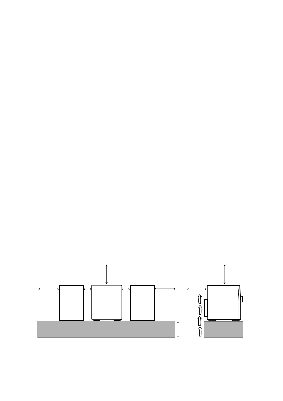
Caution: Proper Ventilation
To avoid risk of electric shock and fire, and to prevent damage, locate
the apparatus as follows:
1 Front:
No obstructions and open spacing.
2 Sides/ Top/ Back:
No obstructions should be placed in the areas shown by the
dimensions below.
3 Bottom:
Place on the level surface. Maintain an adequate air path for
ventilation by placing on a stand with a height of 10 cm or more.
V oorzichtig: Goede ventilatie vereist
Om brand, elektrische schokken en beschadiging te voorkomen, moet
u het toestel als volgt opstellen:
1 Voorkant:
Geen belemmeringen en voldoende ruimte.
2 Zijkanten/boven-/onderkant:
Geen belemmeringen plaatsen in de hieronder aangegeven zones.
3 Onderkant:
Op vlakke ondergrond plaatsen. Voldoende ventilatieruimte voorzien
door het toestel op een onderstel met een hoogte van 10 cm of
meer te plaatsen.
Achtung: Ausreichende Belüftung
Zur Vermeidung von elektrischen Schlägen, Feuer und sonstigen Schäden
sollte das Gerät unter folgenden Bedingungen aufgestellt werden:
1 Vorderseite:
Hindernisfrei und gut zugänglich.
2 Seiten- und Rückwände:
Hindernisfrei in allen gegebenen Abständen (s. Abbildung).
3 Unterseite:
Die Stellfläche muß absolut eben sein. Sorgen Sie für ausreichende
Luftzufuhr durch Aufstellung auf einem Stand mit mindestens 10 cm
Höhe.
Attention: Aération correcte
Pour prévenir tout risque de décharge électrique ou d’incendie et éviter
toute détérioration, installez l’appareil de la manière suivante:
1 Avant:
Bien dégagé de tout objet.
2 Côtés/dessus/dessous:
Assurez-vous que rien ne bloque les espaces indiqués sur le
schéma ci-dessous.
3 Dessous:
Posez l’appareil sur une surface plane et horizontale. Veillez à ce
que sa ventilation correcte puisse se faire en le plaçant sur un support d’au moins dix centimètres de hauteur.
Precaución: ventilación correcta
Para evitar el riesgo de descargas eléctricas e incendio y prevenir
posibles daños, instale el equipo en un lugar que cumpla los siguientes
requisitos:
1 Parte frontal:
Sin obstrucciones, espacio abierto.
2 Lados/parte superior/parte posterior:
No debe haber ninguna obstrucción en las áreas mostradas por las
dimensiones de la siguiente figura.
3 Parte inferior:
Sitúe el equipo sobre una superficie nivelada. Mantenga un espacio
adecuado para permitir el paso del aire y una correcta ventilación,
situando el equipo sobre un soporte de 10 o más cm de allura.
Attenzione: Per una corretta ventilazione
Per prevenire il rischio di scosse elettriche e di incendio ed evitare
possibili danni, collocare le apparecchiature nel modo seguente:
1 Parte anteriore:
Nessun ostacolo e spazio libero.
2 Lati/Parte superiore/Retro:
Lasciare libere le zone indicate dalle dimensioni di seguito.
3 Base:
Collocare su una superficie piana. Consentire un’adeguata
ventilazione dell’impianto appoggiandolo su un tavolinetto alto almeno
10 cm.
Front view Side view
Vorderansicht Seitenansicht
Face Côté
Vooraanzicht Zijaanzicht
Vista frontal Vista lateral
Vista frontale Vista laterale
15 cm
15 cm
1 cm
1 cm
15 cm
15 cm
CA-MXJ300
CA-MXJ200
10 cm
15 cm
CA-MXJ300
CA-MXJ200
– G-3 –
Page 5
IMPORTANT FOR LASER PRODUCTS / WICHTIGER HINWEIS FÜR LASER-PRODUKTE / IMPORTANT POUR LES PRODUITS LASER /
BELANGRIJKE INFORMATIE VOOR LASERPRODUKTEN / IMPORTANTE PARA LOS PRODUCTOS LÁSER / IMPORTANTE PER I
PRODOTTI LASER
REPRODUCTION OF LABELS/ANBRINGUNGSORTE FÜR LASER-PRODUKTE/REPRODUCTION DES ETIQUETTES/VERKLARING VAN
DE LABELS/REPRODUCCIÓN DE ETIQUETAS/RIPRODUZIONE DELLE ETICHETTE
1 CLASSIFICATION LABEL, PLACED ON REAR ENCLOSURE
1 KLASSIFIKATIONSETIKETTE AN DER RÜCKSEITE
1 ETIQUETTE DE CLASSIFICATION, PLACÉE A L'ARRIÈRE DU
COFFRET
1 KLASSIFIKATIELABEL, OP DE ACHTERZIJDE V AN HET
2 WARNING LABEL, PLACED INSIDE THE UNIT
2 WARNETIKETTE IM GERÄTEINNEREN
2 ETIQUETTE D'AVERTISSEMENT PLACÉE À L'INTERIEUR DE
L'APPAREIL
2 WAARSCHUWINGSLABEL, IN HET APPARAA T
APPARAAT
1 ETIQUETA DE CLASIFICACIÓN, PEGADA EN LA PARTE
POSTERIOR DE LA CAJA
1 ETICHETTA DI CLASSIFICAZIONE, SITUATA SUL
RIVESTIMENTO POSTERIORE
2 ETIQUETA DE ADVERTENCIA, PEGADA EN EL INTERIOR DE
LA UNIDAD
2 ETICHETTA DI AVVERTENZA, SITUATA ALL'INTERNO
DELL'APPARECCHIO
CLASS 1
LASER PRODUCT
1. CLASS 1 LASER PRODUCT
2. DANGER: Invisible laser radiation when open and interlock failed
or defeated. Avoid direct exposure to beam.
3. CAUTION: Do not open the top cover. There are no user service-
able parts inside the Unit; leave all servicing to qualified service
personnel.
1. LASER-PRODUKT DER KLASSE 1
2. GEFAHR: Unsichtbare Laserstrahlung bei Öffnung und
fehlerhafter oder beschädigter Spre. Direkten Kontakt mit dem
Strahl vermeiden!
3. ACHTUNG: Das Gehäuse nicht öffnen. Das Gerät enthält
keinerlei Teile, die vom Benutzer gewartet werden können.
Überlassen Sie Wartungsarbeiten bitte qualifizierten
Kundendienst-Fachleuten.
1. PRODUIT LASER CLASSE 1
2. ATTENTION: Radiation laser invisible quand l'appareil est ouvert
ou que le verrouillage est en panne ou désactivé. Eviter une
exposition directe au rayon.
3. ATTENTION: Ne pas ouvrir le couvercle du dessus. Il n'y a
aucune pièce utilisable à l'intérieur. Laisser à un personnel
qualifié le soin de réparer votre appareil.
DANGER: Invisible laser
radiation when open and
interlock failed or defeated.
AVOID DIRECT EXPOSURE
TO BEAM. (e)
VARNING: Osynlig laserstrålning när denna del är
öppnad och spärren är
urkopplad. Betrakta ej
strålen. (s)
ADVARSEL: Usynlig laserstråling ved åbning, når
sikkerhedsafbrydere er ude
af funktion. Undgå udsættelse for stråling (d)
VARO: Avattaessa ja suojalukitus ohitettaessa olet
alttiina näkymättömälle
lasersäteilylle. Älä katso
säteeseen. (f)
1. KLAS 1 LASERPRODUKT
2. GEVAARLIJK: Onzichtbare laserstraling wanneer open en de
beveiliging faalt of uitgeschakeld is. Voorkom het direkt blootstaan
aan de straal.
3. VOORZICHTIG: De bovenkap niet openen. Binnenin het toestel
bevinden zich geen door de gebruiker te repareren onderdelen:
laat onderhoud over aan bekwaam vakpersoneel.
1. PRODUCTO LASER CLASE 1
2. PELIGRO: En el interior hay radiación láser invisible. Evite el
contacto directo con el haz.
3. PRECAUCIÓN: No abra la tapa superior. En el interior de la
unidad no existen piezas reparables por el usuario; deje todo
servicio técnico en manos de personal calificado.
1. PRODOTTO LASER CLASSE 1
2. PERICOLO: Radiazione laser invisibile quando l'apparecchio è
aperto ed il dispositivo di sicurezza è guasto o disattivato. Evitare
l'esposizione diretta ai raggi.
3. A TTENZIONE: Non aprire il coperchio superiore. Non vi sono parti
adoperabili dall'utente all'interno di questo apparecchio; lasciare tutti i
controlli a personale qualificato.
– G-4 –
Page 6
Introduction
English
We would like to thank you for purchasing one of our JVC products.
Before operating this unit, read this manual carefully and thoroughly to
obtain the best possible performance from your unit, and retain this manual
for future reference.
About This Manual
This manual is organized as follows:
• The manual mainly explains operations using the
buttons and controls on the unit. You can also use the
buttons on the remote control if they have the same or
similar names (or marks) as those on the unit.
If operation using the remote control is different from
that using the unit, it is then explained.
• The illustrations used in this manual are of CA-MXJ300.
• Basic and common information that is the same for many
functions is grouped in one place, and is not repeated in
each procedure. For instance, we do not repeat the
information about turning on/off the unit, setting the
volume, changing the sound effects, and others, which are
explained in the section “Common Operations” on pages
11 to 13.
• The following marks are used in this manual:
Gives you warnings and cautions to prevent
from a damage or risk of fire/electric shock.
Also gives you information which is not good
for obtaining the best possible performance
from the unit.
Gives you information and hints you had better
know .
Power sources
• When unplugging from the wall outlet, always pull the
plug, not the AC power cord.
DO NOT handle the AC power cord with wet
hands.
Moisture condensation
Moisture may condense on the lens inside the unit in the
following cases:
• After starting heating in the room
• In a damp room
• If the unit is brought directly from a cold to a warm place
Should this occur, the unit may malfunction. In this case,
leave the unit turned on for a few hours until the moisture
evaporates, unplug the AC power cord, and then plug it in
again.
Others
• Should any metallic object or liquid fall into the unit,
unplug the unit and consult your dealer before operating
any further.
• If you are not going to operate the unit for an extended
period of time, unplug the AC power cord from the wall
outlet.
DO NOT disassemble the unit since there are no
user serviceable parts inside.
Precautions
Installation
• Install in a place which is level, dry and neither too hot nor
too cold — between 5˚C (41˚F) and 35˚C (95˚F).
• Install the unit in a location with adequate ventilation to
prevent internal heat built-up in the unit.
• Leave sufficient distance between the unit and the TV.
• Keep the speakers away from the TV to avoid interference
with TV.
DO NOT install the unit in a location near heat
sources, or in a place subject to direct sunlight,
excessive dust or vibration.
If anything goes wrong, unplug the AC power cord and
consult your dealer.
– 1 –
Page 7

Contents
English
Location of the Buttons and Controls....................... 3
CA-MXJ300 Front Panel ........................................... 4
CA-MXJ200 Front Panel ........................................... 6
Remote Control .......................................................... 7
Getting Started............................................................ 8
Unpacking .................................................................. 8
Putting the Batteries into the Remote Control ........... 8
Connecting Antennas ................................................. 8
Connecting Speakers .................................................. 9
Connecting Other Equipment................................... 10
Common Operations ................................................ 11
Setting the Clock ...................................................... 11
Turning On the Power and Selecting the Sources....... 12
Adjusting the Volume ............................................... 12
Reinforcing the Bass Sound ..................................... 13
Selecting the Sound Modes ...................................... 13
Listening to FM and AM (MW/LW) Broadcasts ... 14
Tuning in a Station ................................................... 14
Presetting Stations .................................................... 14
Tuning in a Preset Station ........................................ 14
Playing Back CDs ..................................................... 15
Loading CDs ............................................................ 15
Playing Back the Entire Discs
— Continuous Play............................................. 15
Basic CD Operations................................................ 15
Programming the Playing Order of the Tracks
— Program Play ................................................. 16
Playing at Random — Random Play ....................... 17
Repeating Tracks or CDs — Repeat Play ................ 18
Prohibiting Disc Ejection — Tray Lock................... 18
Playing Back Tapes ................................................... 19
Playing Back a Tape ................................................. 19
Recording .................................................................. 20
Recording Tapes on Deck B..................................... 20
Dubbing T apes.......................................................... 21
CD Direct Recording................................................. 21
Using the Timers....................................................... 22
Using Daily Timer.................................................... 22
Using Recording Timer............................................ 24
Using Sleep Timer.................................................... 26
Timer Priority........................................................... 26
Maintenance .............................................................. 27
Troubleshooting ........................................................ 28
Specifications............................................................. 28
– 2 –
Page 8
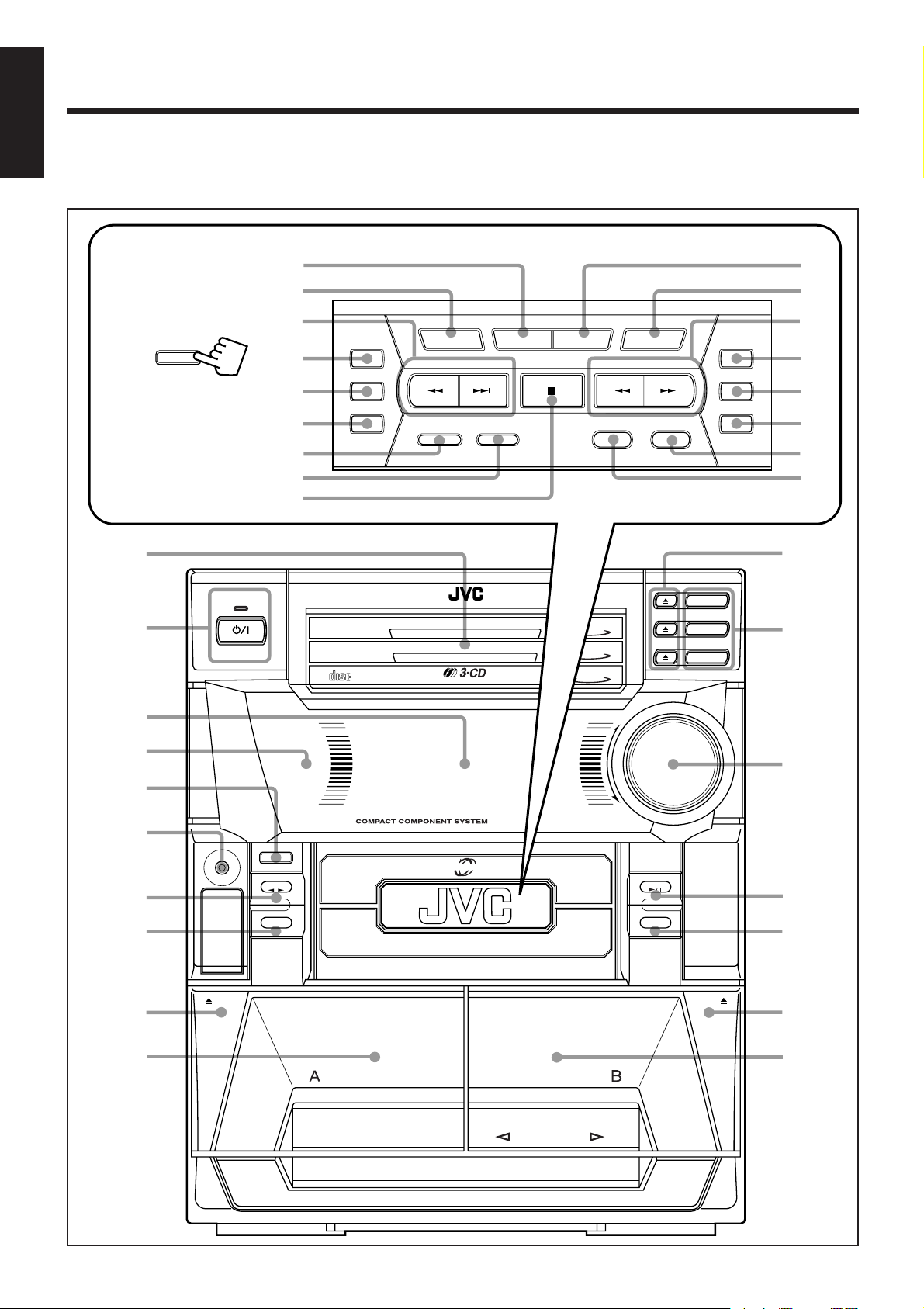
Location of the Buttons and Controls
English
CA-MXJ300
Become familiar with the buttons and controls on your unit.
Powered Rolling Panel
PANEL OPEN /CLOSE
Press PANEL OPEN/
CLOSE to open the panel.
To close the panel, press
the button again.
1
STANDBY
2
3
i
o
;
a
s
d
f
g
h
COMPACT
DIGITAL AUDIO
REC
START/STOP
DUBBING
CD REC START
DEMO
CLOCK/TIMER DISPLAYSET CANCEL
–
PRESET
+–
REVERSE MODE TAPE A/B SOUND MODE ACTIVE BASS EX.
CD
CD
PLAY & EXCHANGE
CD
TUNING
+
3
2
1
VOLUME
+
j
k
l
PROGRAM
/
RANDOM
z
REPEAT
x
c
v
q
CD
3
CD
2
CD
1
w
4
5
6
7
8
9
p
PHONES
COMPU
PLAY
CONTROL
EJECT
1 BIT
DUAL D/A CONVERTER
PANEL OPEN / CLOSE
TAPE
AUX
PLAY
FULL - LOGIC CONTROL
e
–
MX-J300
POWERED ROLLING PANEL
CD
r
FM /AM
t
EJECT
y
u
REC/PLAY
AUTO REVERSE
– 3 –
Page 9
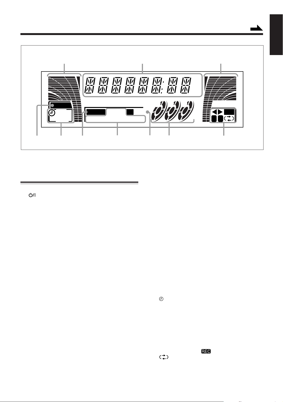
Display Window
Continued
English
112
kHz
MHz
BASS
REC
SLEEP
DAILY
PRGM RANDOM
34 75
See pages in the parentheses for details.
ALL 1 CD
6
ST
MONO
REPEA T
CA-MXJ300 Front Panel
1 Disc trays
2 (standby/on) button and STANDBY lamp (12)
3 Display window
4 Remote sensor
5 PANEL OPEN/CLOSE button (11)
Pressing this button also turns on the unit.
6 PHONES jack (12)
7 TAPE 2 3 button and lamp (19)
Pressing this button also turns on the unit.
8 AUX button and lamp (12)
Pressing this button also turns on the unit.
9 0 EJECT button for deck A (19)
p Deck A cassette holder (19)
q 0 (CD tray open/close) buttons (15)
Pressing one of these buttons also turns on the unit.
w Disc number buttons (CD 1, CD 2, and CD 3) (15, 16, 21)
Pressing one of these buttons also turns on the unit.
e VOLUME control (12)
r CD 6 (play/pause) button and lamp (15)
Pressing this button also turns on the unit.
t FM/AM button and lamp (14)
Pressing this button also turns on the unit.
y EJECT 0 button for deck B (19)
u Deck B cassette holder (19)
Powered Rolling Panel
i SET button (11, 22)
o CLOCK/TIMER button (11, 22)
; PRESET – / + buttons (14)
4 / ¢ (reverse search/forward search) buttons
(11, 16, 22)
4 / ¢ (fast left/fast right) buttons (19)
a REC START/STOP button (20)
231
RECS.MODE
AB
8
s DUBBING button (21)
d CD REC START button (21)
f REVERSE MODE button (19, 21)
g TAPE A/B button (19)
h 7 (stop) button (15, 19)
j CANCEL button (11, 17, 23)
DEMO button (10)
k DISPLAY button (11)
l TUNING – / + buttons (14)
These buttons do not function as 1 / ¡.
/ PROGRAM button (16, 21)
z RANDOM button (17)
x REPEAT button (18)
c ACTIVE BASS EX. (extension) button and lamp (13)
v SOUND MODE button (13)
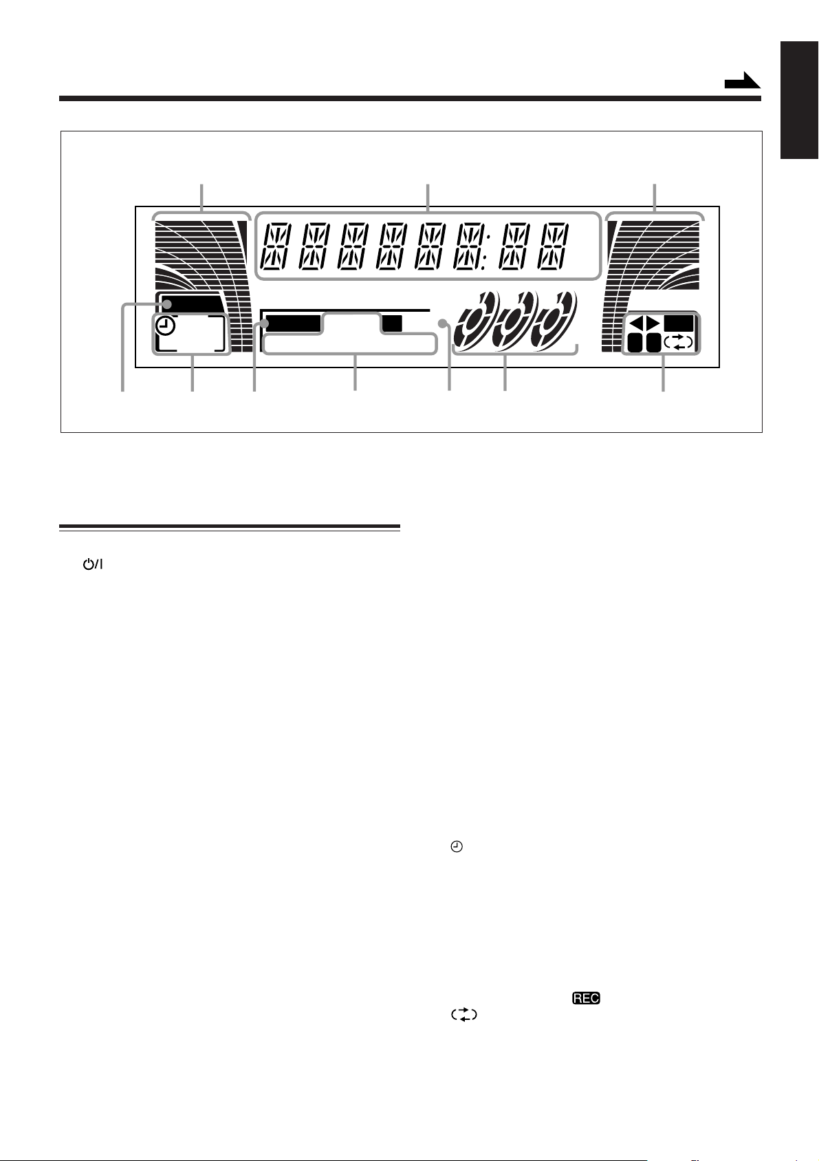
Display window
1 Audio level indicator
2 Main display
• Shows the source name, frequency, etc.
3 BASS (active bass extension) indicator
4 Timer indicators
• , REC, SLEEP, and DAILY indicators
5 S.MODE indicator
6 CD play mode indicators
• PRGM (program), RANDOM and REPEAT
(ALL/1CD/1) indicators
7 Tuner operation indicators
• ST (stereo) and MONO indicators
8 Disc indicators
9 Tape operation indicators
• 2 3 (tape direction), , A/B (operating deck) and
(reverse mode) indicators
9
– 4 –
Page 10
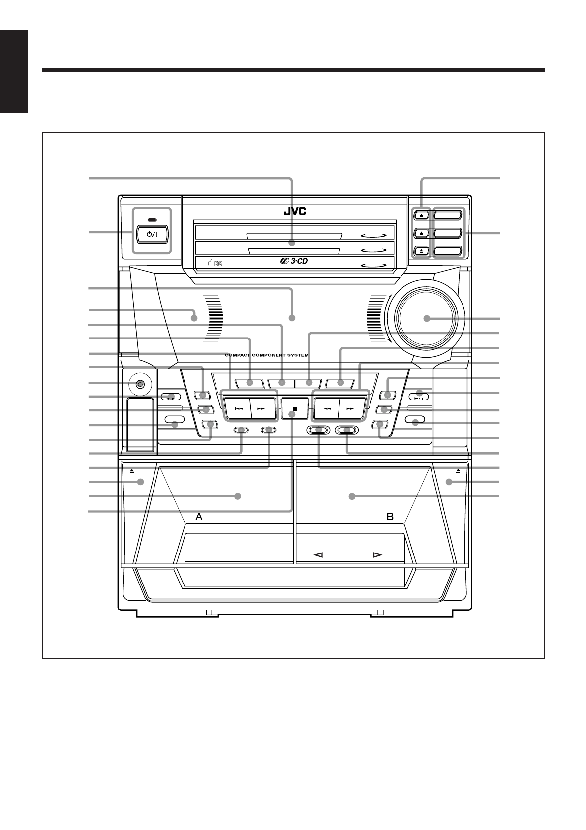
English
CA-MXJ200
Become familiar with the buttons and controls on your unit.
1
2
3
4
5
6
7
8
9
p
q
w
e
r
t
y
u
i
PHONES
COMPU
PLAY
CONTROL
EJECT
STANDBY
1 BIT
DUAL D/A CONVERTER
START/STOP
TAPE
AUX
DIGITAL AUDIO
REC
DUBBING
CD REC START
PLAY
COMPACT
CLOCK/TIMER DISPLAYSET CANCEL
– PRESET +
REVERSE MODE TAPE A/B
PLAY & EXCHANGE
MX-J200
DEMO
–
TUNING +
SOUND MODE ACTIVE BASS EX.
CD
3
CD
2
CD
1
REPEAT
REC/PLAY
PROGRAM
RANDOM
o
CD
3
CD
2
CD
1
VOLUME
+
;
a
s
–
d
f
g
CD
FM /AM
h
j
k
l
/
EJECT
z
x
c
FULL – LOGIC CONTROL
AUTO REVERSE
– 5 –
Page 11
Display Window
Continued
English
112
kHz
MHz
BASS
REC
SLEEP
DAILY
PRGM RANDOM
34 75
See pages in the parentheses for details.
ALL 1 CD
ST
REPEA T
6
CA-MXJ200 Front Panel
1 Disc trays
2 (standby/on) button and STANDBY lamp (12)
3 Display window
4 Remote sensor
5 SET button (11, 22)
6 CLOCK/TIMER button (11, 22)
7 PRESET – / + buttons (14)
4 / ¢ (reverse search/forward search) buttons
(11, 16, 22)
4 / ¢ (fast left/fast right) buttons (19)
8 REC START/STOP button (20)
9 PHONES jack (12)
p TAPE 2 3 button and lamp (19)
Pressing this button also turns on the unit.
q DUBBING button (21)
w AUX button and lamp (12)
Pressing this button also turns on the unit.
e CD REC START button (21)
r REVERSE MODE button (19, 21)
t TAPE A/B button (19)
y 0 EJECT button for deck A (19)
u Deck A cassette holder (19)
i 7 (stop) button (15, 19)
o 0 (CD tray open/close) buttons (15)
Pressing one of these buttons also turns on the unit.
; Disc number buttons (CD 1, CD 2, and CD 3) (15, 16, 21)
Pressing one of these buttons also turns on the unit.
a VOLUME control (12)
s CANCEL button (11, 17, 23)
DEMO button (10)
231
MONO
8
d DISPLAY button (11)
f TUNING – / + buttons (14)
These buttons do not function as 1 / ¡.
g PROGRAM button (16, 21)
h CD 6 (play/pause) button and lamp (15)
Pressing this button also turns on the unit.
j RANDOM button (17)
k FM/AM button and lamp (14)
Pressing this button also turns on the unit.
l REPEAT button (18)
/ ACTIVE BASS EX. (extension) button and lamp (13)
z SOUND MODE button (13)
x EJECT 0 button for deck B (19)
c Deck B cassette holder (19)
Display window
1 Audio level indicator
2 Main display
• Shows the source name, frequency, etc.
3 BASS (active bass extension) indicator
4 Timer indicators
• , REC, SLEEP, and DAILY indicators
5 S.MODE indicator
6 CD play mode indicators
• PRGM (program), RANDOM and REPEAT
(ALL/1CD/1) indicators
7 Tuner operation indicators
• ST (stereo) and MONO indicators
8 Disc indicators
9 Tape operation indicators
• 2 3 (tape direction), , A/B (operating deck) and
(reverse mode) indicators
RECS.MODE
AB
9
– 6 –
Page 12
English
Remote Control
1
2
3
4
5
6
7
8
9
p
q
w
e
r
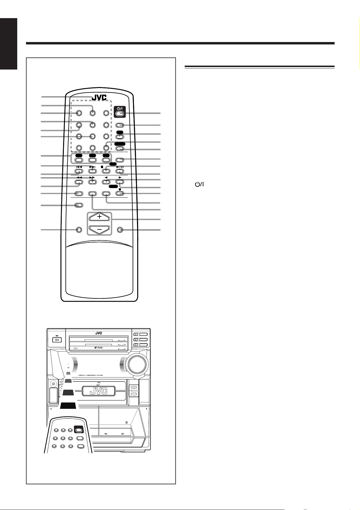
Remote Control
1 Number buttons (14, 16)
2 TIMER button (23, 25)
3 CLOCK button (11)
RM-SMXJ10E REMOTE CONTROL
CLOCK TIMER POWER
1
2 3
–+
SELECT
4 5 6
SET
7 8 9
10 +10
FM MODE
CD3CD2CD1
/CLEAR
SLEEP
AUX
FM/AM
PLAY MODE
C D
t
y
u
i
o
;
a
s
d
f
g
h
REC PAUSE
SHIFT
A – TAPE – B
TAPE
j
SOUND
MODE
VOLUME
ACTIVE
BASS EX.
k
l
CD
STANDBY
COMPACT
DIGITAL AUDIO
1 BIT
DUAL D/A CONVERTER
PHONES
PANEL OPEN / CLOSE
TAPE
COMPU
AUX
PLAY
CONTROL
PLAY & EXCHANGER
POWERED ROLLING PANEL
MX-J300
CD
3
CD
2
CD
1
3
CD
2
CD
1
VOLUME
+
–
CD
FM /AM
4 SELECT + button (11, 23, 25)
5 SELECT – button (11, 23, 25)
6 SET button (11, 23, 25)
7 Disc number buttons (CD 1, CD 2, and CD 3) (15, 16, 21)
Pressing one of these buttons also turns on the unit.
8 ¢ (forward search) button (11, 16, 22)
9 4 (reverse search) button (11, 16, 22)
p ¡ (fast right) button (19)
q 1 (fast left) button (19)
w REC PAUSE button (20)
e SHIFT button (11, 23, 25)
r SOUND MODE button (13)
t (standby/on) button (12)
y SLEEP button (26)
u AUX button (12)
Pressing this button also turns on the unit.
i FM MODE button (14)
o FM/AM button (14)
Pressing this button also turns on the unit.
; PLAY MODE button (16, 17)
a CD 7 (stop) button (15)
CLEAR button (17)
s CD 6 button (15)
Pressing this button also turns on the unit.
d TAPE 2 button (20)
Pressing this button also turns on the unit.
f TAPE 3 button (20)
Pressing this button also turns on the unit.
g TAPE 7 (stop) button (19)
h TAPE B button (19)
j TAPE A button (19)
k VOLUME + / – buttons (12)
l ACTIVE BASS EX. (extension) button (13)
EJECT
PLAY
FULL - LOGIC CONTROL
REC/PLAY
AUTO REVERSE
EJECT
When using the remote control, point it at
the remote sensor on the front panel.
– 7 –
Page 13
Getting Started
Unpacking
Continued
English
Connecting Antennas
After unpacking, check to be sure that you have all the
following items.
The number in the parentheses indicates the quantity of the
pieces supplied.
• AM (MW/LW) loop antenna (1)
• FM antenna (1)
• Remote control (1)
• Batteries (2)
If any is missing, consult your dealer immediately.
Putting the Batteries into the Remote Control
Insert the batteries — R6P/R6PU(SUM-3)/AA(15F) — into
the remote control, by matching the polarity (+ and –) on
the batteries with the + and – markings on the battery
compartment.
When the remote control can no longer operate the unit,
replace both batteries at the same time.
1
2
R6P/R6PU(SUM-3)/
AA(15F)
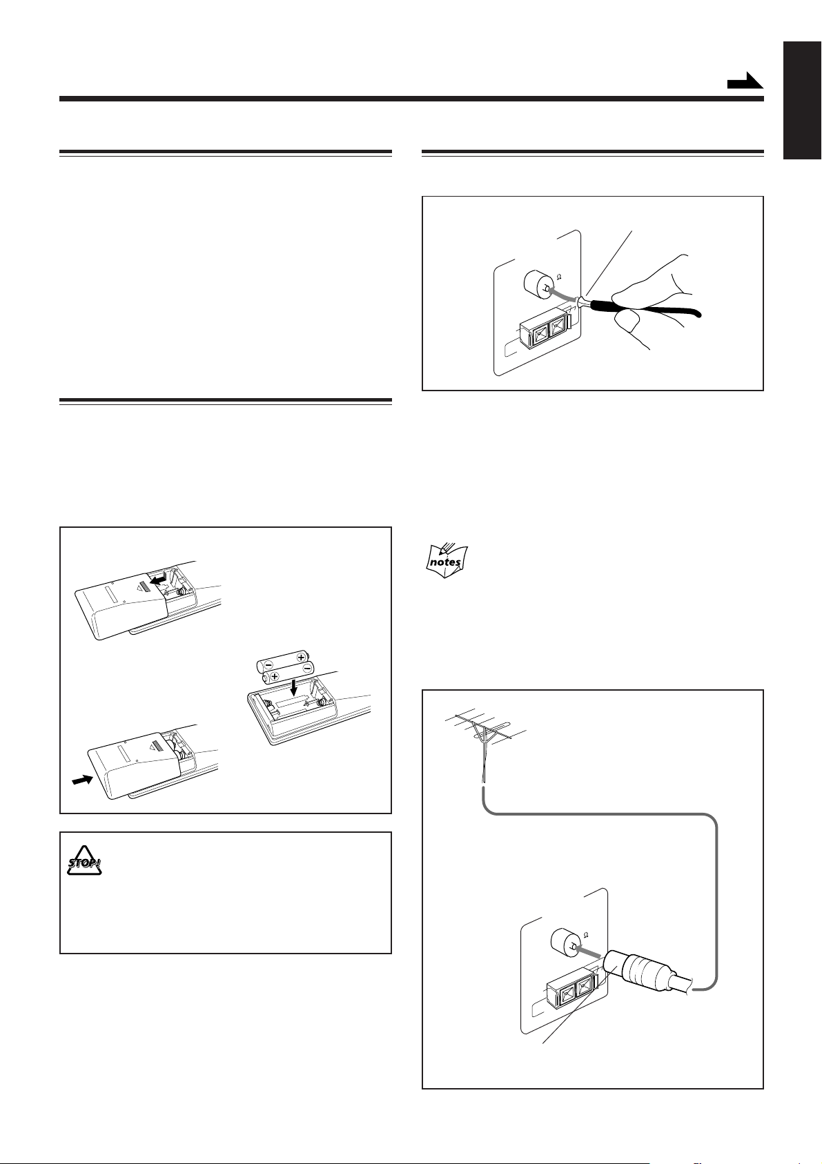
FM antenna
FM antenna (supplied)
ANTENNA
FM 75
COAXIAL
GND
AM
EXT
AM LOOP
1 Attach the FM antenna to the FM 75 Ω
COAXIAL terminal.
2 Extend the FM antenna.
3 Fasten it up in the position which gives you
the best reception.
About the supplied FM antenna
The FM antenna supplied with this unit can be used as temporary
measure. If reception is poor, you can connect an outdoor FM
antenna.
To connect an outdoor FM antenna
Before connecting it, disconnect the supplied FM antenna.
3
• DO NOT use an old battery together with a new one.
• DO NOT use different types of batteries together.
• DO NOT expose batteries to heat or flame.
• DO NOT leave the batteries in the battery
compartment when you are not going to use the
remote control for an extended period of time.
Otherwise, it will be damaged from battery leakage.
Outdoor FM antenna
(not supplied)
ANTENNA
FM 75
COAXIAL
GND
AM
EXT
AM LOOP
A 75Ω antenna with coaxial type connector (DIN 45325)
should be used.
– 8 –
Page 14

English
AM (MW/LW) antenna
AM
EXT
ANTENNA
AM LOOP
231
FM 75
COAXIAL
GND
Vinyl-covered wire
(not supplied)
Connecting Speakers
You can connect a pair of the front speakers.
231
Red
CAUTION:
SPEAKER IMPEDANCE
6~16 OHMS.
SPEAKERS
RIGHT
Speaker
cord
LEFT
Black
Speaker
cord
AM (MW/LW) loop
antenna (supplied)
1 Connect the AM (MW/LW) loop antenna to
the AM LOOP terminals as illustrated.
2 Turn the AM (MW/LW) loop antenna until
you have the best reception.
To connect an outdoor AM (MW/LW) antenna
When reception is poor, connect a single vinyl-covered wire
to the AM EXT terminal and extend it horizontally. (The AM
(MW/LW) loop antenna must remain connected.)
For better reception of both FM and AM (MW/LW)
• Make sure the antenna conductors do not touch any other
terminals and connecting cords.
• Keep the antennas away from metallic parts of the unit,
connecting cords, and the AC power cord.
Right
speaker
Left
speaker
1 Press and hold the clamp of the speaker
terminal on the rear of the unit.
2 Insert the end of the speaker cord into the
terminal.
Match the polarity of the speaker terminals: Red (+) to
red (+) and black (–) to black (–).
3 Release the finger from the clamp.
IMPORTANT: Use only speakers with the same speaker
impedance as indicated by the speaker terminals on the
rear of the unit.
– 9 –
Page 15

Connecting Other Equipment
You can connect an audio equipment — used only as a
playback device.
When you connect and use this equipment, refer also to its
manual.
Be sure that the plugs of the audio cords are color coded:
White plugs and jacks are for left audio signals, and red ones
for right audio signals.
• DO NOT connect any equipment while the power
is on.
• DO NOT plug in any equipment until all
connections are complete.
To connect audio equipment
NOW, you can plug in the unit and other
connected equipment FINALLY!
ANTENNA
FM 75
COAXIAL
AM
EXT
GND
AM LOOP
AUX
IN
RIGHT
LEFT
CAUTION:
SPEAKER IMPEDANCE
6~16 OHMS
SPEAKERS
RIGHT
LEFT
To a wall outlet
English
ANTENNA
FM 75
COAXIAL
AM
EXT
GND
AM LOOP
AUX
IN
RIGHT
LEFT
CAUTION:
SPEAKER IMPEDANCE
6~16 OHMS
SPEAKERS
RIGHT
LEFT
Audio equipment
To audio output
Connect the audio output jacks on the other equipment and
the AUX IN jacks on the rear, using an audio cord (not
supplied).
When connecting the AC power cord into a wall outlet, the
unit automatically starts display demonstration.
To stop the display demonstration, press any button on the
unit or the remote control.
To start the display demonstration manually
Press and hold DEMO for more than 2
seconds.
To stop the demonstration, press any button.
DEMO
CANCEL
– 10 –
Page 16

Common Operations
English
Setting the Clock
Before operating the unit any further, first set the clock built
in this unit.
3
Press SELECT – or + to adjust the
hour, then press SET .
– SELECT +
4
5
For CA-MXJ300 only
Press PANEL OPEN/CLOSE.
The unit is turned on and the Powered
Rolling Panel opens automatically.
On the unit:
1
Press CLOCK/TIMER.
BASS
The hour digits start flashing on the display.
2
Press 4 or ¢ to adjust the
hour, then press SET .
BASS
• If you want to correct the hour after pressing
SET, press CANCEL. The hour digits start
flashing again.
3
Press 4 or ¢ to adjust the
minute, then press SET.
ST
ST
RECSOUND MODE
RECSOUND MODE
PANEL OPEN / CLOSE
–
– PRESET +
CLOCK/TIMER
PRESET
+
SET
BASS
ST
RECSOUND MODE
SET
8
• If you want to correct the hour after pressing
SET, press CANCEL (on the unit). The hour
digits start flashing again.
4
Press SELECT – or + to adjust the
– SELECT +
4
minute, then press SET.
BASS
To check the clock time
Press DISPLAY while playing any source.
• Each time you press the button, the source
indication and the clock time alternate on the
display.
To adjust the clock again
If you have adjusted the clock before, you need to press
CLOCK/TIMER repeatedly until the clock setting mode is
selected.
• Each time you press the button, the clock/timer setting
modes change as follows:
DAILY
Canceled
ON TIME
Clock
setting
(The hour digits start flashing.)
ST
RECSOUND MODE
REC
ON TIME
SET
8
DISPLAY
5
BASS
On the remote control:
1
Press SHIFT.
2
Press CLOCK.
BASS
The hour digits start flashing on the display.
ST
RECSOUND MODE
ST
RECSOUND MODE
SET
SHIFT
CLOCK
1
The clock loses the setting and is reset to “0:00.” You need to set the
clock again.
If there is a power failure
– 11 –
Page 17

Continued
Turning On the Power and Selecting the
Sources
When you press the play button for a particular source (FM/
AM, CD 6, T APE 2 3, and AUX), the unit turns on. (For
CA-MXJ300 only, the Powered Rolling Panel opens
automatically .)
The unit starts playing the source if it is ready — COMPU
PLAY CONTROL.
To listen to the FM/AM (MW/LW) broadcasts, press FM/
AM. (See page 14.)
To play back CDs, press CD 6. (See pages 15 – 18.)
To play back tapes, press T APE 2 3. (See page 19.)
To select the external equipment as the source, press AUX.
FM /AM
CD
To turn on the unit without playing, press
(standby/on) so that the STANDBY lamp goes off.
BASS
(For CA-MXJ300 only, the Powered Rolling Panel opens
automatically .)
TAPE
AUX
STANDBY
ST
RECSOUND MODE
Adjusting the Volume
You can adjust the volume level only while the unit is turned
on.
Turn VOLUME clockwise to increase the
volume or counterclockwise to decrease
it.
BASS
ST
RECSOUND MODE
When using the remote control, press VOLUME + to increase
the volume or press VOLUME – to decrease it.
For private listening
Connect a pair of headphones to the PHONES jack. No sound
comes out of the speakers. Be sure to turn down the volume before
connecting or putting on headphones.
DO NOT turn off (on standby) the unit with the
volume set to an extremely high level; otherwise, a
sudden blast of sound can damage your hearing,
speakers and/or headphones when you turn on the
unit or start playing any source next time.
REMEMBER you cannot adjust the volume level
while the unit is on standby .
VOLUME
+
–
English
To turn off the unit (on standby), press
STANDBY
(standby/on) again so that the STANDBY lamp
lights up.
(For CA-MXJ300 only, the Powered Rolling Panel
also closes.)
A little power is always consumed even while the unit is on
standby.
To switch off the power supply completely, unplug the AC
power cord from the AC outlet.
When you unplug the AC power cord or if a power
failure occurs
The clock is reset to “0:00” right away, while the tuner preset
stations (see page 14) will be erased in a few days.
– 12 –
Page 18

English
Reinforcing the Bass Sound
The richness and fullness of the bass sound is maintained
regardless of how low you set the volume.
You can use this effect only for playback.
To get the effect, press ACTIVE BASS EX.
BASS
ST
RECSOUND MODE
ACTIVE BASE EX.
The BASS indicator also lights up on the display .
To cancel the effect, press the button again.
Selecting the Sound Modes
You can select one of the 6 preset sound modes (3 surround
modes and 3 SEA – Sound Effect Amplifier – modes). The
sound modes can be applied only to playback sounds, and
cannot be used for recording.
To select the sound modes, press SOUND
MODE until the sound mode you want appears on
the display.
BASS
S.MODE
ST
REC
SOUND MODE
The S.MODE indicator also lights up on the display.
• Each time you press the button, the sound modes change as
follows:
D.CLUB
(Dance CLUB)
OFF
(Canceled)
HALL STADIUM ROCK
CLASSIC
POP
Surround modes:
D.CLUB: Increases resonance and bass.
HALL: Adds depth and brilliance to the sound.
STADIUM: Adds clarity and spreads the sound, like in an
outdoor stadium.
SEA modes:
ROCK: Boosts low and high frequency . Good for
acoustic music.
POP: Good for vocal music.
CLASSIC: Good for classical music.
OFF: Cancels the sound mode.
– 13 –
Page 19

Listening to FM and AM (MW/LW) Broadcasts
Tuning in a Station
On the unit ONLY:
2
Press SET.
English
SET
1
Press FM/AM.
The unit automatically turns on and tunes in
the previously tuned station (either FM or AM
— MW/L W). (For CA-MXJ300 only, the
Powered Rolling Panel automatically opens.)
• Each time you press the button, the band alternates
between FM and AM (MW/LW).
2
Press and hold TUNING – / + for
FM /AM
– TUNING +
more than 1 second.
The unit starts searching for stations and
stops when a station of sufficient signal
strength is tuned in.
If a program is broadcast in stereo, the ST (stereo)
indicator lights up.
To stop during searching, press TUNING – / +.
When you press TUNING – / + briefly and repeatedly
The frequency changes step by step.
To change the FM reception mode
When an FM stereo broadcast is hard to receive
or noisy, press FM MODE on the remote control
so that the MONO indicator lights up on the
display. Reception improves.
To restore the ster eo effect, press FM MODE again so that
the MONO indicator goes off.
In this stereo mode, you can hear stereo sounds when a
program is broadcast in stereo.
FM MODE
BASS
3
Press PRESET – / + to select a
ST
– PRESET +
preset number.
BASS
4
Press SET again.
BASS
The tuned station in step 1 is stored in the preset number
selected in step 3.
• Storing a new station on a used number erases the
previously stored one.
When you unplug the AC power cord or if a power
failure occurs
The preset stations will be erased in a few days. If this happens,
preset the stations again.
ST
RECSOUND MODE
SET
ST
Tuning in a Preset Station
1
Press FM/AM.
The unit automatically turns on and tunes in
the previously tuned station (either FM or
AM — MW/L W.) (For CA-MXJ300 only, the
Powered Rolling Panel automatically opens.)
• Each time you press the button, the band alternates
between FM and AM (MW/LW).
FM /AM
Presetting Stations
You can preset 30 FM and 15 AM (MW/LW) stations.
In some cases, test frequencies have been already memorized
for the tuner since the factory examined the tuner preset
function before shipment. This is not a malfunction. You can
preset the stations you want into memory by following the
presetting method.
• There is a time limit in doing the following steps. If the
setting is canceled before you finish, start from step 1
again.
1
Tune in the station you want to preset.
• See “Tuning in a Station” above.
MHz
BASS
ST
RECSOUND MODE
2
– 14 –
Select a preset number.
On the unit:
Press PRESET – / +.
On the remote control:
Press the number buttons.
For preset number 5, press 5.
For preset number 15, press +10
then 5.
For preset number 20, press +10,
then 10.
For preset number 25, press +10,
+10, then 5.
– PRESET +
1 2 3
4 5 6
7 8 9
10+10
Page 20

Playing Back CDs
English
Loading CDs
1
Press 0 for the disc tray (CD 1 to 3)
you want to load a CD onto.
The unit automatically turns on and the disc
tray comes out. (For CA-MXJ300 only, the
Powered Rolling Panel also opens
automatically .)
2
Place a disc correctly on the circle of the disc
tray, with its label side up.
Playing Back the Entire Discs — Continuous
Play
You can play CDs continuously.
1
Load CDs.
2
Press one of the disc number
buttons (CD 1, CD 2, and CD 3)
for the disc you want to play.
CD play starts from the first track of the
selected disc.
Track number Elapsed playing time
CD
3
CD
2
CD
1
CORRECT
• When using a CD single (8 cm), place it on the inner
circle of the disc tray.
3
Press the same 0 you have pressed
INCORRECT
in step 1.
The disc tray closes, and the corresponding
disc number indicator (CD 1 to CD 3) lights
up on the display.
4
Repeat steps 1 to 3 to place other CDs.
When loading more than one CD continuously
When you press 0 for the next tray you want to place another CD
onto, the first disc tray automatically closes and then the next tray
comes out.
About the disc indicators
Each disc indicator corresponds to the disc tray of the same number.
Disc number
Disc indicator
Disc marker
2 31
BASS
• Pressing CD 6 instead of the disc number buttons
starts playing back if a CD is on the trays.
To stop during play, press 7 on the unit (or CD 7/CLEAR
on the remote control).
To remove the disc, press 0 for the corresponding disc tray.
CD playback sequence
When 3 CDs are loaded in the disc trays, they are played in one of
the following sequences.
• When CD 1 is pressed : CD 1 ] CD 2 ] CD 3 (then stops)
• When CD 2 is pressed : CD 2 ] CD 3 ] CD 1 (then stops)
• When CD 3 is pressed : CD 3 ] CD 1 ] CD 2 (then stops)
* When only 2 CDs are loaded, they are played in the same order,
but the disc tray without a CD is skipped.
231
ST
RECSOUND MODE
Basic CD Operations
While playing a CD, you can do the following operations.
To exchange CDs during playback of another
Press 0 corresponding to a CD, not playing or selected
currently, to eject and exchange the CD.
If you exchange CDs during play, the current play will not
stop until all CDs you have exchanged are played.
• The disc marker lights up for the disc number you have selected.
• The disc indicator flashes while the corresponding CD is being
played.
• The disc indicator goes off when the unit has detected that there is
no CD on the corresponding disc tray.
– 15 –
To stop play for a moment
Press CD 6.
BASS
While pausing, the elapsed playing time flashes on the
display.
To resume play, press CD 6 again.
231
ST
RECSOUND MODE
CD
Page 21

Continued
–
PRESET
To locate a particular point in a track
+
During play, press and hold 4 or ¢.
• 4 : Fast reverses the disc.
• ¢ : Fast forwards the disc.
To go to another track
– PRESET +
Press 4 or ¢ repeatedly before or during
playback.
• 4:Goes back to the beginning of the
current or previous tracks.
• ¢:Skips to the beginning of the next or
succeeding tracks.
If you press and hold 4 / ¢ before playing
You can change the tracks continuously.
To go to another track directly using the number
buttons
Pressing the number button(s) before or during play allows
you to start playing the track number you want.
When a track number button is pressed, CD play starts from
the track of the currently selected disc.
Ex.: For track number 5, press 5.
For track number 15, press +10 then 5.
For track number 20, press +10, then 10.
For track number 32, press +10 , +10, +10, then 2.
1 2 3
4 5 6
7 8 9
2
Select the Program play mode.
On the unit:
Press PROGRAM.
On the remote control:
Press PLAY MODE repeatedly until the
PRGM indicator lights on the display. Each
time you press the button, the CD play
mode changes as follows:
Program play = Ramdom play = Continuous play
= (back to the beginning)
BASS
231
PRGM
ST
RECSOUND MODE
• If a program has been stored in memory, the program is
called up.
3
Press one of the disc number
buttons (CD 1, CD 2, and CD 3)
to select the disc number you
want to play.
Track number
Disc number
BASS
PRGM
4
Select a track from the CD selected in the
Program step number
231
ST
PLAY MODE
CD
CD
CD
RECSOUND MODE
above step.
On the unit:
Press 4 or ¢ to select the track number,
then press SET.
– PRESET +
SET
English
PROGRAM
3
2
1
10+10
Programming the Playing Order of the Tracks
— Program Play
You can arrange the order in which the tracks play before you
start playing. You can program up to 32 tracks.
• To use Repeat play for Program play, press REPEAT after
starting Program play.
1
Load discs.
• If the current playing source is not the CD player, press
CD 6, then 7 on the unit (or CD 7/CLEAR on the
remote control) before going to the next step.
– 16 –
On the remote control:
1 2 3
Press the number buttons.
• For how to use the number
buttons, see “To go to another
track directly using the number
buttons” described to the left.
BASS
PRGM
5
Program other tracks you want.
231
• To program tracks from the same disc, repeat step 4.
• To program tracks from a different disc, repeat steps 3
and 4.
6
Press CD 6.
The tracks are played in the order you have programed.
4 5 6
7 8 9
10 +10
ST
RECSOUND MODE
Page 22

English
To stop during play, press 7 on the unit (or CD 7/CLEAR
on the remote control).
To exit from program play mode
On the unit:
Press PROGRAM again before or after play so that the unit
enters Continuous play mode.
On the remote control:
Press PLAY MODE repeatedly until all the CD play mode
indicator go off from the display.
• The program you have made is stored in memory until you
erase the program.
To check the program contents
Before playing, you can check the program contents by
pressing 4 or ¢ on the remote control.
• ¢ : Shows the programed tracks in the programed order.
• 4: Shows them in the reverse order.
Playing at Random — Random Play
The tracks of all loaded CDs will play at random.
• To use Repeat play for Random play, press REPEAT after
starting Random play.
1
Prepare CDs.
• If the current playing source is not the CD player, press
CD 6, then 7 on the unit (or CD 7/CLEAR on the
remote control) before going to the next step.
2
Select the Random play mode.
On the unit:
Press RANDOM.
BASS
231
RANDOM
ST
RECSOUND MODE
RANDOM
To modify the program
Before play, you can erase the programed tracks
shown on the display by pressing CANCEL.
• Each time you press the button, the programed
track shown on the display is erased from the
program.
To add tracks in the program before play, simply select the
disc numbers and the track numbers you want to add by
following steps 3 and 4 of the programming procedure on
page 16.
To erase the entire program before or after play, press 7
on the unit (or CD 7/CLEAR on the remote control).
“PROGRAM” appears on the display.
• Ejecting a CD will also erase the track numbers programed
from the ejected CD.
If you try to program a 33rd step
“FULL” will appear on the display.
If your entry is ignored
You have tried to program a track from an empty tray, or a track
number that does not exist on the CD (for example, selecting track
14 on a CD that only has 12 tracks). Such entries are ignored.
DEMO
CANCEL
On the remote control:
PLAY MODE
Press PLAY MODE repeatedly until the
RANDOM indicator lights on the display.
Each time you press the button, the CD play
mode changes as follows:
Program play = Random play = Continuous play
= (back to the beginning)
3
Press CD 6.
The tracks are played at random.
CD
Random play ends when all the tracks are
played once.
To stop during play, press 7 on the unit (or CD 7/CLEAR
on the remote control).
• Random play also stops when one of the disc trays is
opened.
To exit from Random play mode, press RANDOM again
before or after play so that the unit enters Continuous play
mode.
Even if you press 4
You cannot go back to the previous tracks during Random play.
• If you press ¢, you can go to next random tracks.
– 17 –
Page 23

Repeating Tracks or CDs — Repeat Play
You can have all the CDs, the program or the individual track
currently playing repeat as many times as you like.
English
To repeat play, press REPEAT during or before
REPEAT
playing. To use Repeat play for Program play and
Random play, press the button after starting
playback.
• Each time you press the button, Repeat play mode changes
as follows, and the following indicator lights up on the
display:
REPEAT ALL REPEAT 1CD
Canceled
(Continuous play)
REPEAT 1
REPEA T ALL: Repeats all the tracks on all the CDs
(continuously or at random), or all the
tracks in the program.
REPEAT 1CD*:Repeats all the tracks on one CD.
REPEAT 1: Repeats one track on one CD.
* REPEAT 1CD is not used for Program play and Random
play.
To cancel Repeat play, press REPEAT repeatedly until the
REPEAT indicator (REPEAT ALL, REPEAT 1CD, or
REPEAT 1) goes off from the display.
• Repeat play is also canceled when you press PROGRAM
or RANDOM.
Prohibiting Disc Ejection — Tray Lock
You can prohibit CD ejection from the unit and can lock
discs.
• This operation is possible only using the buttons on the
unit.
To prohibit disc ejection, press 0 for any disc tray while
holding 7. (If there is any disc tray opened, close it first.)
“LOCKED” appears for a while, and the loaded CDs are
locked.
To cancel the prohibition and unlock the CDs, press 0 for
any disc tray while holding 7.
“UNLOCKED” appears for a while, and the loaded CDs are
unlocked.
If you try to eject CDs
“LOCKED” appears to inform you that the Tray Lock is in use.
– 18 –
Page 24

0 EJECT
0 EJECT
Playing Back Tapes
0 EJECT
English
This unit provides two types of cassette deck: Deck A for
one-way playing only and deck B for Reverse Mode playing
as well as one-way playing.
You can play back type I, type II and type IV tapes without
changing any settings.
Playing Back a Tape
1
Press EJECT (0) for the deck you want to
use.
For deck A
For deck B
To fast wind to the left or to the right, press 4 or ¢ (or
1 or ¡ on the remote control).
The tape direction indicator (2 3) starts flashing quickly on
the display.
To remove the cassette, press 0 EJECT for deck A or
EJECT 0 for deck B.
To play both sides repeatedly — Reverse Mode
Reverse Mode works for deck B.
When it is in use, the tape automatically reverses at the end of
a side and the unit starts playing the other side of the tape,
and repeats the same process.
To use Reverse Mode, press REVERSE MODE
so that the Reverse Mode indicator on the display
lights up as — .
REVERSE MODE
2
Put a cassette in, with the exposed part of the
tape down.
3
Close the cassette holder gently.
If you put cassettes in both decks A and B, the last deck
you have put a cassette into is selected.
To operate the other deck, press TAPE A/B (or TAPE A
or TAPE B on the remote control).
4
On the unit:
22
Press TAPE
2
22
33
3.
33
On the remote control:
Press TAPE
direction playback, or press TAPE
33
3 for forward
33
22
2 for
22
reverse direction playback.
• Each time you press the button, the display changes to
show the following:
: The Cassette Deck automatically stops
after playing both sides of the tape.
(Stops when playback in the 2 direction
is finished.)
: The Cassette Deck continues to play both
sides of the tape until the 7 button is
pressed.
: The Cassette Deck automatically stops
after playing one side of the tape.
TAPE
To cancel Reverse Mode, press the button again so that the
Reverse Mode indicator on the display lights up as — .
When the deck A is selected:
The tape plays only the front side and the tape direction
indicator (3) starts flashing slowly.
When the tape plays to the end, the deck automatically stops.
When the deck B is selected:
The tape play starts and the tape direction indicator
(2 3) starts flashing slowly to indicate the tape
running direction.
• Each time you press the button, the tape direction
changes:
33
3 : plays the front side.
33
22
2 : plays the reverse side.
22
When the tape plays to the end, the deck automatically
stops if the Reverse Mode is not on. (See “To play both
sides repeatedly — Reverse Mode.”)
To stop during play, press 7.
To operate the other deck, press TAPE A/B (or TAPE A or
TAPE B on the remote control), then TAPE 2 3.
The use of the C-120 or thinner tape is not
recommended, since characteristic deterioration
may occur and this tape easily jams in the pinchrollers and the capstans.
– 19 –
Page 25

Recording
0 EJECT
0 EJECT
IMPORTANT:
• It may be unlawful to record or play back copyrighted
material without the consent of the copyrighted owner.
• The recording level is automatically set correctly, so it is
not affected by the VOLUME control. Thus, during
recording you can adjust the sound you are actually
listening to without affecting the recording level.
• While recording, you can hear sound modes and/or the
active bass extension effect through the speakers or
headphones. However, the sound is recorded without these
effects (see page 13).
• If recordings you have made have excessive noise or static,
the unit may be too close to a TV. Increase the distance
between the TV and the unit.
• You can use type I and II tapes for recording.
Continued
Recording Tapes on Deck B
1
Press EJECT 0 for the deck B.
2
Put in a recordable cassette, with the exposed
part of the tape down.
3
Close the cassette holder gently.
English
To protect your recording
Cassettes have two small tabs on the back to protect
unexpected erasure or re-recording.
T o protect your recording, remove these tabs.
To re-record on a protected tape, cover the holes with
adhesive tape.
When using type II tape, be careful not to cover the holes
used to detect the tape type.
Type II detection
slot
Adhesive tape
4
Check the tape direction of deck B.
• If the tape direction is not correct, press TAPE 2 3
twice then 7 to change the tape direction.
• If you want to record on both sides of a tape, press
REVERSE MODE until the indicator is lit.
5
Start playing the source — FM, AM*, CD
player, deck A, or auxiliary equipment
connected to AUX jacks.
• When the source is CD, you can also use CD Direct
Recording (see page 21).
• When the source is deck A, you can also use the
dubbing method. (See “Dubbing Tapes” on page 21.)
* See “To record an AM (MW/LW) station – Beat Cut” on page
21.
6
Start recording.
On the unit:
Press REC START/STOP.
The indicator lights up on the display and
recording starts.
On the remote control:
1) Press REC P AUSE.
The indicator starts flashing on
the display.
2) Press TAPE 2 or TAPE 3.
The indicator stops flashing and
remains lit, and recording starts.
REC PAUSE
2 3
REC
START/STOP
TAPE
To stop during recording, press REC START/STOP again,
or press 7.
– 20 –
Page 26

English
To stop recording temporarily (except when the playback
source is deck A), press REC PAUSE on the
remote control.
The REC indicator flashes on the display.
To resume recording, press TAPE 2 3 on the
unit (or TAPE 2 or TAPE 3 on the remote control).
The REC indicator stops flashing and remains lit.
REC PAUSE
CD Direct Recording
Everything on the CD goes onto the tape in the order it is on
the CD, or according to the order you have made for Program
play.
1
Put a recordable cassette into deck B.
To remove the cassette, press EJECT 0 for deck B.
To record on both sides — Reverse Mode
Press REVERSE MODE so that the Reverse Mode
indicator lights up as — .
• When using the Reverse Mode for recording,
start recording in the forward (3) direction first.
Otherwise, recording will stop when recording is done only
on one side (reverse) of the tape.
To cancel Reverse Mode, press the button again so that the
Reverse Mode indicator lights up as — .
REVERSE MODE
To record an AM (MW/LW) station — Beat Cut
While recording an AM (MW/LW) broadcast, beats may be
heard (which are never heard when listening to the broadcast
without recording it).
If this occurs, press PROGRAM repeatedly, while
recording, until the beats are reduced.
• Each time you press the button, the display
changes to show the following:
CUT 1
CUT 2
PROGRAM
Dubbing Tapes
When dubbing tapes, make sure that the playback direction of
deck A and deck B are the same.
1
Press TAPE 2 3, then 7.
2
Put the source cassette in deck A, and a
recordable cassette into deck B.
• Put the cassettes in both decks so that the tapes will run
in the forward (3) direction.
2
Place a disc correctly on the circle of the disc
tray, with its label side up.
CD
3
Press one of the disc number
buttons (CD 1 to CD 3) to select
3
CD
2
the disc, then 7.
CD
1
4
Press CD REC START.
“CD REC” appears, and the indicator
lights up on the display.
Deck B starts recording and the CD player
starts playing.
When the recording is done, “CD REC FINISHED”
appears on the display, and the CD player and deck B
stop.
To stop during CD Direct Recording, press 7.
To remove the cassette, press EJECT 0 for deck B.
To record on both sides — Reverse Mode
Press REVERSE MODE so that the Reverse Mode indicator
lights up as — .
• When using the Reverse Mode for CD Direct Recording,
put a recordable cassette tape into deck B with the font side
facing the holder and start recording in the forward (3)
direction first. When the tape reaches its end while
recording a song in the forward direction (3), the last song
will be recorded at the beginning of the reverse side (2).
If you start recording on the reverse side (2), recording
will stop when recording is done only on one side (reverse)
of the tape.
To cancel Reverse Mode, press the button again so that the
Reverse Mode indicator lights up as — .
CD REC START
3
Press DUBBING.
Dubbing starts.
To stop during dubbing, press 7.
To remove the cassette, press 0 EJECT for deck A and
EJECT 0 for deck B.
DUBBING
To record on both sides — Reverse Mode
Press REVERSE MODE so that the Reverse Mode indicator
lights up as — .
To cancel Reverse Mode, press the button again so that the
Reverse Mode indicator lights up as — .
– 21 –
Page 27

Using the Timers
There are three timers available — Recording Timer, Daily
Timer, and Sleep Timer.
Before using the timers, you need to set the clock built in the
unit. (See page 11.)
Using Daily Timer
With Daily Timer, you can wake to your favorite music or
radio program.
How Daily Timer actually works
The unit automatically turns on, set the volume level to the
preset level, and starts playing the specified source when the
on-time comes (the indicator flashes just before the ontime, and continues flashing while the timer is operating).
Then, when the off-time comes (“OFF” flashes just before the
off-time), the unit automatically turns off (stands by).
The timer setting remains in memory until you change it.
• There is a time limit in doing the following steps. If the
setting is canceled before you finish, start from step 1
again.
• If you have made a mistake while setting timer, press
CANCEL. (However, this does not always work. If
CANCEL does not work, press CLOCK/TIMER repeatedly
and start from step 1 again.)
Continued
3
Set the on-time you want the unit
– PRESET +
to turn on.
1) Press 4 or ¢ to set the hour, then
press SET.
2) Press 4 or ¢ to set the minute, then press
SET .
“OFF TIME” appears for 2 seconds, then
the unit enters off-time setting mode.
4
Set the off-time you want the unit
–
to turn off (on standby).
1) Press 4 or ¢ to set the hour, then
press SET.
2) Press 4 or ¢ to set the minute, then
press SET.
The unit enters source selecting mode.
5
Press 4 or ¢ to select the source to play,
then press SET.
• Each time you press 4 or ¢, the source changes as
follows:
TUNER FM
AUX
TAPE
TUNER AM
– CD – – –
– PRESET +
SET
PRESET
SET
English
+
On the unit:
1
Press CLOCK/TIMER until
“DAILY” appears on the display.
REC
ST
RECSOUND MODE
ST
RECSOUND MODE
BASS
DAIL Y
The DAILY indicator also starts flashing on the display.
• Each time you press the button, the timer setting mode
changes as follows:
DAILY
Canceled
2
Press CLOCK/TIMER again.
ON TIME
Clock
setting
(See page 11.)
ON TIME
“ON TIME” appears for 2 seconds, then the
unit enters on-time setting mode.
BASS
DAIL Y
CLOCK/TIMER
CLOCK/TIMER
BASS
DAIL Y
ST
RECSOUND MODE
SET
TUNER FM: tunes into a specified preset FM station. =
go to step 6.
TUNER AM: tunes into a specified preset AM (MW/LW)
station. = go to step 6.
– CD – – –: plays a disc from a specified track of a
specified disc. = go to step 6.
• Make sure there is a CD on the selected disc
number tray.
T APE: plays a tape in deck A or B. = go to step 7.
• Make sure that a tape is in the deck whose deck
indicator (A or B) is lit on the display.
• Make sure that the tape direction is correct.
AUX: plays an external source.= go to step 7.
• To use this setting, the external component has to
be equipped with the timer function.
BASS
DAIL Y
ST
RECSOUND MODE
– 22 –
Page 28

English
6
7
8
When selecting “– CD – – –”
1) Press 4 or ¢ to select the disc
–
PRESET
number, then press SET.
2) Press 4 or ¢ to set the track
number, then press SET.
The unit enters volume setting mode.
When selecting “TUNER FM” or
SET
“TUNER AM”
Press 4 or ¢ to select the preset station
number, then press SET.
The unit enters volume setting mode.
Press 4 or ¢ to set the volume
– PRESET +
level.
• You can select the volume level from
among four levels. If you select “ VOL – –
–,” the volume is set to the last level when
the unit has been turned off.
BASS
DAIL Y
Press SET to complete the Daily
ST
RECSOUND MODE
SET
Timer setting.
The DAILY indicator stops flashing and remains
lit. The settings you have done are shown on the display
in sequence.
On the remote control:
+
1
Press SHIFT.
2
Press TIMER.
BASS
DAIL Y
The DAILY indicator also starts flashing on the display.
• Each time you press the button, the timer setting mode
changes as follows:
DAILY = ON TIME = REC = ON TIME =
Clock setting
3
Press TIMER again.
“ON TIME” appears for 2 seconds, then the
unit enters on-time setting mode.
BASS
DAIL Y
(See page 11.) = Canceled
SHIFT
TIMER
2
ST
RECSOUND MODE
TIMER
2
ST
RECSOUND MODE
9
Press (standby/on) to turn off the
STANDBY
unit (on standby) if you have set the
Daily Timer with the unit turned on.
To turn on or off Daily Timer after its setting is done
1 Press CLOCK/TIMER repeatedly until
“DAILY” appears on the display.
2 To turn off the Daily Timer, press
CANCEL.
The DAILY indicator goes off and “OFF”
appears on the display.
The Daily Timer is canceled, but the setting for
the Daily Timer remains in memory.
To turn on the Daily Timer, press SET.
The DAILY indicator lights up on the display.
The settings you have done are shown on the
display in sequence for your confirmation.
If the unit is turned on when the timer-on time comes
Daily Timer does not work.
CLOCK/TIMER
DEMO
CANCEL
SET
BASS
DAIL Y
4
Set the on-time you want the unit
to turn on.
1) Press SELECT – or SELECT + to set
the hour, then press SET.
2) Press SELECT – or SELECT + to set
the minute, then press SET.
“OFF TIME” appears for 2 seconds, then
the unit enters off-time setting mode.
5
Set the off-time you want the unit to
turn off (on standby).
1) Press SELECT – or SELECT + to set
the hour, then press SET.
2) Press SELECT – or SELECT + to set
the minute, then press SET.
The unit enters source selecting mode.
ST
RECSOUND MODE
– SELECT +
4
SET
8
– SELECT
4
SET
8
5
+
5
– 23 –
Page 29

6
Press SELECT – or SELECT + to
select the source to play, then
– SELECT
4
press SET.
• Each time you press SELECT – or
SELECT +, the source changes as
follows:
TUNER FM
AUX
BASS
DAIL Y
TAPE
TUNER AM
– CD – – –
ST
RECSOUND MODE
TUNER FM: tunes into a specified preset FM station.
= go to step 7.
TUNER AM: tunes into a specified preset AM (MW/LW)
station. = go to step 7.
– CD – – –: plays a disc from a specified track of a
specified disc. = go to step 7.
• Make sure there is a CD on the selected disc
number tray.
TAPE: plays a tape in deck A or B. = go to step 8.
• Make sure that a tape is in the deck whose deck
indicator (A or B) is lit on the display.
• Make sure that the tape direction is correct.
AUX: plays an external source.= go to step 8.
• To use this setting, the external component has to
be equipped with the timer function.
7
When selecting “– CD – – –”
1) Press SELECT – or SELECT + to
– SELECT +
4
select the disc number, then press
SET.
2) Press SELECT – or SELECT + to set
the track number, then press SET.
The unit enters volume setting mode.
When selecting “TUNER FM” or
SET
8
“TUNER AM”
Press SELECT – or SELECT + to select the
preset station number, then press SET.
The unit enters volume setting mode.
8
Press SELECT – or SELECT +
to set the volume level.
• You can select the volume level from
among four levels. If you select “ VOL –
– –,” the volume is set to the last level
when the unit has been turned off.
– SELECT +
4
8
SET
5
5
Continued
English
+
10
5
Press (standby/on) to turn off
the unit (on standby) if you have set
the Daily Timer with the unit
turned on.
Using Recording Timer
With Recording Timer, you can make a tape of a radio
broadcast automatically.
How Recording Timer actually works
The unit automatically turns on, tunes into the specified
station, sets the volume level to “MIN,” and starts recording
when the on-time comes (the indicator flashes just before
the on-time, and continues flashing while the timer is
operating). Then, when the off-time comes (“OFF” appears
just before the off-time), the unit automatically turns off
(stands by).
The timer setting remains in memory until you change it.
• There is a time limit in doing the following steps. If the
setting is canceled before you finish, start from step 1
again.
• If you have made a mistake while setting the timer, press
CANCEL. (However, this does not always work. If
CANCEL does not work, press CLOCK/TIMER repeatedly
and start from step 1 again.)
On the unit:
1
Put a recordable cassette into deck B.
2
Press CLOCK/TIMER until
“REC” appears on the display.
REC
The REC indicator also starts flashing on the display.
• Each time you press the button, the timer setting mode
changes as follows:
DAILY
Canceled
3
Press CLOCK/TIMER again.
ON TIME
Clock
setting
(See page 11.)
ON TIME
“ON TIME” appears for 2 seconds, then the
unit enters on-time setting mode.
REC
ST
REC
ST
CLOCK/TIMER
RECSOUND MODE
CLOCK/TIMER
RECSOUND MODE
BASS
DAIL Y
9
Press SET to complete the Daily
Timer setting.
The DAILY indicator stops flashing and
remains lit. The settings you have done are
shown on the display in sequence.
ST
RECSOUND MODE
SET
8
REC
ST
RECSOUND MODE
– 24 –
Page 30

English
4
5
6
7
Set the on-time you want the unit
to turn on.
1) Press 4 or ¢ to set the hour, then
press SET.
2) Press 4 or ¢ to set the minute,
then press SET.
“OFF TIME” appears for 2 seconds, then
the unit enters off-time setting mode.
Set the off-time you want the unit
to turn off (on standby).
1) Press 4 or ¢ to set the hour, then
press SET.
2) Press 4 or ¢ to set the minute,
then press SET.
The unit enters preset station selecting
mode.
Select the preset station.
1) Press 4 or ¢ to select the band
(“TUNER FM” or “TUNER AM”), then
press SET.
2) Press 4 or ¢ to select a preset
channel number, then press SET.
The REC indicator stops flashing and
remains lit. The settings you have done are
shown on the display in sequence.
Press (standby/on) to turn off the
unit (on standby) if necessary.
– PRESET +
SET
–
PRESET
SET
–
PRESET
SET
STANDBY
On the remote control:
1
Put a recordable cassette into deck B.
2
Press SHIFT.
3
Press TIMER until “REC” appears
+
on the display.
REC
ST
RECSOUND MODE
The REC indicator also starts flashing on the display.
• Each time you press the button, the timer setting mode
changes as follows:
+
DAILY = ON TIME = REC = ON TIME =
Clock setting
4
Press TIMER again.
(See page 11.) = Canceled
“ON TIME” appears for 2 seconds, then the
unit enters on-time setting mode.
REC
ST
RECSOUND MODE
SHIFT
TIMER
2
TIMER
2
If you want to listen to another source while
recording
Press REC START/STOP to stop recording. Without stopping it, you
cannot change the source.
To turn on or off Recording Timer after its setting is
done
1 Press CLOCK/TIMER repeatedly until
“REC” appears on the display.
2 To turn off the Recording Timer, press
CANCEL (on the unit only).
The REC indicator goes off and “OFF” appears
on the display.
The Recording Timer is canceled, but the setting
for the Recording Timer remains in memory.
To turn on the Recording Timer, press SET.
The REC indicator lights up on the display. The
settings you have done are shown on the display
in sequence for your confirmation.
CLOCK/TIMER
DEMO
CANCEL
SET
REC
5
Set the on-time you want the unit
to turn on.
1) Press SELECT – or SELECT + to set
the hour, then press SET.
2) Press SELECT – or SELECT + to set
the minute, then press SET.
“OFF TIME” appears for 2 seconds, then
the unit enters off-time setting mode.
6
Set the off-time you want the unit to
turn off (on standby).
1) Press SELECT – or SELECT + to set
the hour, then press SET.
2) Press SELECT – or SELECT + to set
the minute, then press SET.
The unit enters source selecting mode.
ST
RECSOUND MODE
– SELECT +
4
5
SET
8
– SELECT
4
+
5
SET
8
– 25 –
Page 31

7
Select the preset station.
1) Press SELECT – or SELECT + to select
the band (“TUNER FM” or “TUNER
AM”), then press SET.
2) Press SELECT – or SELECT + to select
a preset channel number, then press SET.
The REC indicator stops flashing and
remains lit. The settings you have done are
shown on the display in sequence.
8
Press to turn off the unit (on
standby) if necessary.
– SELECT +
4
SET
8
English
Timer Priority
5
Since each timer can be set separately, you may wonder what
happens if the setting for these timers overlaps.
Here are examples.
• Recording Timer has priority over Daily Timer and
Sleep Timer .
If Daily Timer is set to come on while Recording Timer is
operating, Daily Timer will not come on at all.
Recording Timer
Daily Timer
6:00
6:30
does not work.
7:307:00
Using Sleep Timer
With Sleep Timer, you can fall asleep to music.
You can set Sleep Timer when the unit is turned on.
How Sleep Timer actually works
The unit automatically turns off after the specified time
length passes.
On the remote control ONLY:
1
Press SLEEP.
The time length until the shut-off time appears
and the SLEEP indicator starts flashing on the
display.
• Each time you press the button, the time length changes
as follows:
10
2
Wait for about 5 seconds after specifying the
30 60 90 120
20
Canceled
time length.
The SLEEP indicator stops flashing and remains lit.
SLEEP
If Recording Timer is set to come on while Sleep Timer is
operating, Sleep Timer will not work (the SLEEP indicator
does not go off).
7:30
7:00
does not work.
Recording Timer
Sleep Timer
6:00
6:30
To check the remaining time until the shut-off time, press
SLEEP once so that the remaining time until the shut-off time
appears for about 5 seconds.
To change the shut-off time, press SLEEP repeatedly until
the desired time length appears on the display.
To cancel the setting, press SLEEP repeatedly so that the
SLEEP indicator goes off.
• Sleep Timer is also canceled when you turn off the unit.
– 26 –
Page 32

Maintenance
English
To get the best performance of the unit, keep your discs, tapes, and mechanism clean.
Handling discs
• Remove the disc from its case by
holding it at the edge while pressing the
center hole lightly.
• Do not touch the shiny surface of the
disc, or bend the disc.
• Put the disc back in its case after use to
prevent warping.
• Be careful not to scratch the surface of
the disc when placing it back in its
case.
• A void exposure to direct sunlight,
temperature extremes, and moisture.
To clean the disc
Wipe the disc with a soft cloth in a
straight line from center to edge.
Handling cassette tapes
• If the tape is loose in its cassette, take
up the slack by inserting a pencil in
one of the reels and rotating.
• If the tape is loose, it may get
stretched, cut, or caught in the
cassette.
• Be careful not to touch the tape
surface.
• A void the following places to store the
tape:
— In dusty places
— In direct sunlight or heat
— In moist areas
— Near a magnet
DO NOT use any solvent — such as conventional
record cleaner, spray, thinner, or benzine — to
clean the disc.
Cassette decks
If the heads, capstans, and pinch rollers of the cassette
decks become dirty, the following will occur:
• Impaired sound quality
• Discontinuous sound
• Fading
• Incomplete erasure
• Difficulty in recording
To clean the heads, capstans, and pinch rollers
Use a cotton swab moistened with alcohol.
Pinch rollers
Capstans
Heads
To demagnetize the heads
Turn off the unit, and use a head demagnetizer (available at
electronics and record shops).
– 27 –
Page 33

Troubleshooting
If you are having a problem with your unit, check this list for a possible solution before calling for service.
If you cannot solve the problem from the hints given here, or the unit has been physically damaged, call a qualified person,
such as your dealer, for service.
Symptom
No sound is heard.
Hard to listen to broadcasts because of
noise.
The disc sound is discontinuous.
The disc tray does not open or close.
The disc does not play.
The cassette holders cannot be opened.
Impossible to record.
Operations are disabled.
Unable to operate the unit from the remote
control unit.
Connections are incorrect or loose.
• Antennas are disconnected.
• The AM (MW/LW) loop antenna is too
close to the unit.
• The FM antenna is not properly extended
and positioned.
The disc is scratched or dirty.
• The AC power cord is not plugged in.
• Trays are locked.
The disc is placed upside down.
Power supply from the AC power cord has
been cut off while the tape was running.
Small tabs on the back of the cassette are
removed.
The built-in microprocessor may
malfunction due to external electrical
interference.
• The path between the remote control unit
and the remote sensor on the unit is
blocked.
• The batteries are exhausted.
Cause
Action
Check all connections and make
corrections. (See pages 8 to 10.)
• Reconnect the antennas correctly and
securely.
• Change the position and direction of the
AM (MW/LW) loop antenna.
• Extend the FM antenna at the best
position.
Clean or replace the disc. (See page 27.)
• Plug the AC power cord.
• Unlock the trays. (See page 18.)
Place the disc with the label side up.
Turn on the unit.
Cover the holes with adhesive tape.
Unplug the AC power cord and then plug it
back in.
• Remove the obstruction.
• Replace the batteries.
English
Specifications
Amplifier
Output Power
CA-MXJ300: 70 W per channel, min. RMS, both channels driven
into 6 Ω at 1 kHz with no more than 10% total
harmonic distortion
CA-MXJ200: 40 W per channel, min. RMS, both channels driven
into 6 Ω at 1 kHz with no more than 10% total
harmonic distortion
Audio input sensitivity/Impedance (at 1 kHz)
AUX: 300 mV/50 kΩ
Speakers/Impedance: 6 Ω – 16 Ω
Tuner
FM tuning range: 87.50 MHz – 108.00 MHz
AM tuning range: MW: 522 kHz – 1,629 kHz
LW: 144 kHz – 288 kHz
CD player
CD Capacity: 3 CDs
Dynamic range: 85 dB
Signal-to-noise ratio: 90 dB
W ow and flutter: Immeasurable
Design and specifications are subject to change without notice.
Cassette deck
Frequency response
Normal (type I): 50 Hz — 14,000 Hz
CrO2 (type II): 50 Hz — 14,000 Hz
Metal (type IV): 50 Hz — 14,000 Hz (only for playback)
W ow and flutter
0.15% (WRMS)
General
Power requirement: AC 230 V , 50 Hz
Power consumption:
CA-MXJ300: 95 W (at operation)
8 W (on standby)
CA-MXJ200: 85 W (at operation)
9 W (on standby)
Dimensions (approx.): 265 mm x 315 mm x 361 mm (W/H/D)
Mass (approx.):
CA-MXJ300: 8.7 kg (19.2 lbs)
CA-MXJ200: 7.2 kg (15.9 lbs)
7
(10
/16 in. x 12 7/16 in. x 14 1/4 in.)
Supplied accessories
See page 8.
– 28 –
Page 34

VICTOR COMPANY OF JAPAN, LIMITED
EN, GE, FR, NL, SP, IT
JVC
0400KSMMDWHIT
Page 35

INSTRUCTIONS
SPEAKER SYSTEM
SP-MXJ300, SP-MXJ200
BEDIENUNGSANLEITUNG: LAUTSPRECHERSYSTEM
MANUEL D’INSTRUCTIONS: SYSTEME DES ENCEINTES
GEBRUIKSAANWIJZING: LUIDSPREKERSYSTEEM
MANUAL DE INSTRUCCIONES: SISTEMA DE ALTAVOCES
ISTRUZIONI: SISTEMA DI ALTOPARLANTI
BRUKSANVISNING: HÖGTALARSYSTEM
Thank you for purchasing JVC speakers.
Before you begin using them, please read the instructions carefully to be
sure you get the best possible performance. If you have any questions,
consult your JVC dealer.
Vielen Dank für den Kauf dieser JVC-Lautsprecher.
Lesen Sie bitte diese Bedienungsanleitung vor Ingebrauchnahme sorgfältig
durch, um stets optimale Ergebnisse zu erzielen. Wenden Sie sich bei
etwaigen Fragen bitte an Ihren JVC Händler.
Nous vous remercions pour l’achat de ces enceintes JVC.
Avant de les utiliser , lire ces instructions avec attention pour en obtenir les
meilleures performances possibles. En cas de questions, consulter votre
revendeur JVC.
Dank u voor de aanschaf van deze luidsprekers.
Lees alvorens over te gaan tot aansluiten, dez e gebruiksaanwijzing door
zodat u de best mogelijke prestaties zult verkrijgen. Neem kontakt op met
de JVC dealer indien u vragen heeft.
Le estamos muy agradecidos por haber adquirido estos altavoces de JVC .
Antes de utilizarlos, sirvase leer las instrucciones detenidamente a fin de
obtener el mejor rendimiento posible. Si tienenaluna pregunta, acuda a
su agente de JVC.
Grazie per aver acquistato questi altoparlanti della JVC.
Prima di cominciare l’uso degli altoparlanti, leggete attentamente le
istruzioni per assicurare le migliori prestazioni. Qualora sorgessero dei
dubbi, rivolgetevi al vostro rivenditore JVC.
VEJLEDNING: HØJTTALERSYSTEM
KÄYTTÖOHJE: KAIUTINJÄRJESTELMÄ
INSTRUKCJA UŻYTKOWANIA: ZESTAW GŁOŚNIKOWY
HASZNÁLATI ÚTMUTATÓ: HANGSZÓRÓ RENDSZER
NÁVOD K OBSLUZE: REPRODUKTOROVÁ SOUSTAVA
Tack för ditt val av dessa JVC-högtalare.
Innan du kopplar in högtalarna i din ljudanläggning bör du för att få
maximala prestanda från högtalarna läsa igenom bruksanvisningen
noggrant. Kontakta din JVC-återförsäljare om du har frågor eller känner
dig osäker.
Tak for købet af JVC-højttalerne.
Gennemlæs venligst vejledningen omhyggeligt før de tages i brug, så De
kan opnå den bedst mulige ydelse. Forhør hos Deres JVC forhandler hvis
De har nogen spørgsmål.
Kiitos siitä että päädyit valinnassasi JVC-kaiuttimiin.
Ennen kuin alat käyttää niitä, lue käyttöohje huolellisesti, jotta ne toimisivat
parhaalla mahdollisella tavalla. Jos Sinulla on kysyttävää ota yhte ys JVCedustajaan.
Dziękujemy za wybranie zestawu głośnikowego firmy JVC.
Przed rozpoczęciem użytkowania zestawu głośnikowego prosimy o
dokładne zapoznanie się z treścią niniejszej instrukcji użytkowania, aby
uzyskać jak najlepszą pracę głośników. W przypadku jakichkolwiek
zapytań, prosimy o skonsultowanie się z najbliższym dealerm firmy JVC.
Köszönjük, hogy a JVC hangszóró rendszerét választotta. Annak
érdekében, hogy a hangszóró rendszer a legjobb teljesítményt nyújtsa
Önnek, használat előtt kérjük figyelmesen olvassa el ezt a használati
útmutatót. Ha bármilyen kérdése van, forduljon a legközelebbi JVC
márkakereskedőhöz.
Děkujeme Vám, že jste si zakoupili reproduktory JVC.
Dříve než je začnete používat, přečtěte si prosím pečlivě návod k obsluze,
abyste dosáhli co nejlepší možné funkce. Jestliže máte další otázky, spojte
se s svým prodejcem JVC.
— SAFETY INSTRUCTIONS —
“SOME DOS AND DON’TS ON THE SAFE USE OF EQUIPMENT”
This equipment has been designed and manufactured to meet
international safety standards but, like any electrical equipment, care
must be taken if you are to obtain the best results and safety is to be
assured.
Do read the operating instructions before you attempt to use the
equipment.
Do ensure that all electrical connections (including the mains plug,
extension leads and interconnections between pieces of equipment)
are properly made and in accordance with the manufacturer’s
instructions. Switch off and withdraw the mains plug when making or
changing connections.
Do consult your dealer if you are ever in doubt about the installation,
operation or safety of your equipment.
Do be careful with glass panels or doors on equipment.
DON’T continue to operate the equipment if you are in any doubt
about it working normally, or if it is damaged in any way — switch off,
withdraw the mains plug and consult your dealer.
DON’T remove any fixed cover as this may expose dangerous
voltages.
DON’T leave equipment switched on when it is unattended unless it
is specifically stated that it is designed for unattended operation or
has a standby mode.
Switch off using the switch on the equipment and make sure that
your family know how to do this.
Special arrangements may need to be made for infirm of handicapped people.
DON’T use equipment such as personal stereos or radios so that
you are distracted from the requirements of traffic safety. It is illegal
to watch television whilst driving.
DON’T listen to headphones at high volume as such use can
permanently damage your hearing.
DON’T obstruct the ventilation of the equipment, for example with
curtains or soft furnishing.
Overheating will cause damage and shorten the life of the equipment.
DON’T use makeshift stands and NEVER fix legs with wood screws
— to ensure complete safety always fit the manufacturer’s approved
stand or legs with the fixings provided according to the instructions.
DON’T allow electrical equipment to be exposed to rain or moisture.
ABOVE ALL
– NEVER let anyone, especially children, push anything into holes,
slots or any other opening in the case.
– this could result in a fatal electrical shock;
– NEVER guess or take chances with electrical equipment of any
kind
– it is better to be safe than sorry!
LVT0485-001A
1
1
[B. E. EN. EV]
Page 36

Amplifier connection
Ver stärkeranschluß
Raccordement à l'amplificateur
Aansulaiten op de versterker
Anslutning till en förstärkare
Conexión al amplificador
Collegamento dell'amplificatore
Forstærkertilslutning
Vahvistimen liitäntä
Połączenia ze wzmacniaczem
Erősítő csatlakoztatás
Zapojení zesilovače
Right speaker
Rechter Lautsprecher
Enceinte droite
Rechter luidspreker
Altavoz derecho
Altoparlante destro
Höger högtalare
Højre højttaler
Oikeanpuoleinen kaiutin
Prawa kolumna
Jobb hangszóró
Pravý reproduktor
Amplifier output terminals
Ausgang des Verstärkers
Bornes de sortie de l'amplificaterur
Uitgangsaansluitengen van de versterker
Terminales de salida de amplificador
Terminali de uscita dell'amplifcator
Utgångar på förstärkaren
Forstærkerudgangsbøsninger
Vahvistimen ulostuloliittimet
Przyłącza wyjścia ze wzmacniacza
Erősítő kimeneti csatlakozók
Výstupní zdířky zesilovače
SPEAKERS
RIGHT LEFT
Left speaker
Linker Lautsprecher
Enceinte gauche
Linker luidspreker
Altavoz izquierdo
altoparlante sinistro
Vänster högtalare
Venstr højttaler
Vasemmanpuoleinen kaiutin
Lewa kolumna
Bal hangszóró
Levý reproduktor
CONNECTION
• Turn off power to the whole system before connecting the
speakers to the amplifier.
• The nominal impedance of the SP-MXJ300, SP-MXJ200 is 6
Ω. Select for use an amplifier to which a speaker system with
the load impedance of 6 Ω can be connected.
• The maximum power handling capacity of the SP-MXJ300 is
100W and the SP-MXJ200 is 60W . Excessive input will result
in abnormal noise and possible damage. In cases where the
signals described below are applied to the speakers, even if
the signals are below the maximum allowab le input, they ma y
cause an overload and burn the wiring of the speakers. Be
sure to lower the amplifier volume beforehand.
1) Noise during FM tuning.
2) High level signals containing high frequency components
produced by a tape deck in the fast forward mode.
3) Click noise produced when turning power of other components on and off.
4) Click noise produced when connecting or disconnecting
cords with the power on.
5) Click noise produced when the car tridge is replaced with
the power on.
6) Click noise produced when operating amplifier switches.
7) Continuous high frequency oscillation or high pitch electronically produced musical instrument sound.
8) Howling when using a microphones.
Black Svart
Schwarz Sort
Noir Musta
Zwart Czarny
Negro Fekete
Nero Černý
SPECIFICATIONS
Type : 2-way 2-speaker bass-reflex
type
Speaker units : Dual Duct System
Woofer : 16 cm (6-5/16 in.) cone × 1
Tweeter : 4 cm (1-5/8 in.) cone × 1
Power Handling Capacity
SP-MXJ300 : 100 W
SP-MXJ200 : 60 W
Impedance : 6 Ω
Frequence Range : 45 Hz - 22 000 Hz
Sound Pressure Level : 88 dB/W·m
Dimensions (W × H × D) : 215 mm × 315 mm × 273 mm
(8-1/2 in. × 12-7/16 in. × 10-3/4 in.)
Mass : 3.5 kg (7.8 lbs) each
Design and specifications subject to change without notice.
2
2
Page 37

ANSCHLUSS
•
Schalten Sie vor dem Anschluß der Lautsprecher an den V erstärker
die Spannungsversorgung des gesamten Systems aus.
• Die
Nennimpedanz der Lautsprecher — Systeme SP-MXJ300,
SP-MXJ200 beträgt 6 Ω. Wählen Sie einen Verstärker, an den
ein Lautsprechersystem mit einer Lastimpedanz von 6 Ω
angeschlossen werden kann.
• Die maximale Belastbarkeit ist 100 W für SP-MXJ300 und 60 W
für SP-MXJ200. Eine Überlastung führt zu Verzerrungen und
möglicherweise zu Beschädigungen.
Signale der unten beschriebenen Art können, auch wenn sie
unter dem maximal zulässigen Eingang liegen, eine Überlastung
verursachen und die Lautsprecherwicklungen durchbrennen.
Verringern Sie vorher die Lautstärke des Verstärkers.
1) Geräusche beim Einstellen von UKW-Sendern.
2) Hochpegelige Signale mit Hochfrequenz-Anteilen, die von
Tonbanddecks beim Schnellvorspulen erzeugt werden.
3) Klickgeräusche, wenn die Spannungsversorgung anderer
Komponenten ein- und ausgeschaltet wird.
Klickgeräusche, wenn Kabel angeschlossen oder abgetrennt
4)
werden, während die Spannungsversorgung eingeschaltet ist.
5) Klickgeräusche, wenn der Tonabnehmer des Plattenspielers
ausgewechselt wird, während die Spannungsversorgung
eingeschaltet ist.
6) Klickgeräusche, die beim Betätigen von Schaltern des
Verstärkers erzeugt werden.
7) Ständige Hochfrequenzschwingungen oder elektronisch
erzeugte Töne von Musikinstrumenten mit hohen Tonhöhen.
8) Rückkopplungen von Mikrofonen.
RACCORDEMENT
• Mettre hors circuit tout le système avant de raccorder les
enceintes à l’amplificateur.
• L ’impédance nominale des enceintes SP-MXJ300, SP-MXJ200
est de 6 Ω. Sélectionner un amplificateur acceptant une
impédance de charge de haut-parleur de 6 Ω.
• La puissance maximale admissible de la SP-MXJ300 est de
100 W et celle de la SP-MXJ200 est de 60 W.
En dépassant la puissance admissible, cela provoquera des
bruits anormaux et détériorera les enceintes.
Au cas où les signaux décrits ci-dessous sont envoyés aux
enceintes, et même si ces signaux sont inférieurs à la puissance d’entrée maximum admissible, ils risquent de prov oquer
une surcharge ou même un incendie. S’assurer de bien diminuer
le volume sonore de l’amplificateur.
1) Parasites durant une syntonisation FM.
2) Signaux de niveau élevé contenant des composants à haute
fréquence, comme ceux générés par une platine
d’enregistrement en mode avance rapide.
3) Cliquetis se produisant lorsque d’autres appareils sont mis
en ou hors circuit.
4) Cliquetis se produisant lorsque des appareils sont branchés
ou dé-branchés alors que leur alimentation est en circuit.
5) Cliquetis se produisant lorsque la cellule d’une platine tournedisque est changée alors que l’alimentation est en circuit.
6) Cliquetis se produisant lorsque les commandes de
l’amplificateur sont manipulées.
7) Oscillations continuelles à haute fréquence ou sons très aigus
provenant d’instruments de musique électroniques.
8) Hurlements dus à l’utilisation de micros.
TECHNISCHE DATEN
Typ : 2-Weg, 2-Lautsprecher-
Baßreflexbox
Lautsprechereinheiten : Dual Duct System
Tieftöner : 16 cm – Konus × 1
Hochtöner : 4 cm – Konus × 1
Belastbarkeit
SP-MXJ300 : 100 W
SP-MXJ200 : 60 W
Impedanz : 6 Ω
Frequenzbereiche : 45 Hz - 22 000 Hz
Schalldruckpegel : 88 dB/W·m
Abmessungen (W × H × T) : 215 mm × 315 mm × 273 mm
Gewicht : je 3,5 kg.
Technische Änderungen vorbehalten.
CARACTERISTIQUES
T ype : Enceinte 2 v oies, 2 haut-parleurs
type à réflexion des basses
Enceintes : Dual Duct System
Graves : conique de 16 cm × 1
Aigus : conique de 4 cm × 1
Puissance admissible
SP-MXJ300 : 100W
SP-MXJ200 : 60W
Impédance : 6 Ω
Gamme de fréquence : 45 Hz - 22 000 Hz
Niveau de pression sonore
Dimensions (L × H × P) : 215 mm × 315 mm × 273 mm
Masse : 3,5 kg chaque
: 88 dB/W·m
Présentation et caractéristiques modifiables sans préavis.
3
3
Page 38

AANSLUITINGEN
• Schakel de spanning van alle aangesloten componenten uit
alvorens de luidsprekers met de versterker te verbinden.
• De nominale impedantie van de SP-MXJ300, SP-MXJ200
bedraagt 6 Ω.
Kies daarom een versterker waarop u een luidspekersysteem
kunt aansluiten met een impedantie belasting van 6 Ω.
• Het maximum verwerkingsvermogen van de SP-MXJ300 is 100
W en van de SP-MXJ200, 60 W. Te hoge ingang kan in
abnormale geluidsreproductie en in beschadigingen resulteren.
Overbelasting en verbranding van de bedrading kan worden
veroorzaakt wanneer de hieronder beschreven signalen naar
de luidspekers worden gev oed, zelfs wanneer de signalen onder
het maximaal toegestane ingangsvermogen zijn. Verminder
eerst het volume van de versterker.
1) Ruis, zoals dit optreedt tijdens afstemming op een FM-z ender.
2) Hoogfreguentie signalen van een hoog niveau, zoals die
tijdens het vooruitspoelen van een tapedeck worden
geproduceerd.
3) Klikkende geluiden, die worden veroorzaakt door het in - en
uitschakelen van de netspanning van andere componenten.
4) Klikkende geluiden, zoals die worden geproduceerd bij het
tot stand brengen of verbreken van aansluitingen terwijl de
netspanning is ingeschakeld.
5) Klikkende geluiden, zoals die optreden bij het vervangen van
het element van een draaitafel terwijl de netspanning is
ingeschakeld.
6) Klikkende geluiden, zoals die worden geproduceerd door
bediening van de schakelaars van de versterker.
7) Voortdurende hoogfrekwentie-oscillatie, of hoogtonige,
elektronisch geproduceerde geluiden van
muziekinstrumenten.
8) Rondzingend geluid bij gebruik van mikrofoons.
CONEXIÓN
• Desactive la alimentación de todo el sistema antes de conectar
los altavoces al amplificador.
• La impedancia nominal del SP-MXJ300, SP-MXJ200 es de 6
Ω. Seleccione un amplificador al que puedan conectarse
altavoces con una impedancia de carga de 6 Ω.
• La potencia máxima admisible del SP-MXJ es de 100 W y la
del SP-MXJ200 es de 60 W.
Uná entrada excesiva resultará en ruido anormal y posibles
daños.
En casos donde las señales descritas más abajo se apliquen a
los altavoces, aunque las mismas resulten menores que la
entrada máxima permisible, pueden causar una sobrecarga y
quemar el cableado de los altavoces. Asegúrese de disminuir
el volumen del amplificador con anterioridad.
1) Ruido durante la sintonia en FM.
2) Señales de alto nivel que contengan componentes de alta
frecuencia producidos por un magnetófono en el modo de
avance rápido.
3) Ruidos de conmutación provocados al encender y apagar
otros componentes.
4) Ruido de conmutación al conectar o desconectar cables con
los componentes encendidos.
5) Ruido de conmutación cuando se reemplaza la cápsula con
los componentes encendidos.
6) Ruido de conmutación provocados por la operación de los
selectores del amplificador.
7) Continua oscilación de alta frecuencia o de sonidos de tonos
altos provocados por instrumentos electrónicos.
8) Aullidos al utilizar micrófonos.
TECHNISCHE GEGEVENS
Type : 2 tweeweg luidsprekers 2 bass
reflex
Luidsprekers : Dual Duct System
Woofer : 16 cm - kegeltype × 1
Tweeter : 4 cm - kegeltype × 1
Toegestane vermogenverwerking
SP-MXJ300 : 100 W
SP-MXJ200 : 60 W
Impedantie : 6 Ω
Freguentiekarakteristiek : 45 Hz - 22 000 Hz
Geluidsdrukniveau : 88 dB/W·m
Afmetingen (B × H × D) : 215 mm × 315 mm × 273 mm
Gewicht : Elk 3,5 kg
Veranderingen in technische gegevens en ontwerp onder
voorbehoud.
ESPECIFICACIONES
Tipo : Reflex bajo con 2-altavoces
y 2 vias
Unidades de altavoces : Dual Duct System
De grvaes : Tipo cónico de 16 cm × 1
De agudos : Tipo cónico de 4 cm × 1
Potencia máxima
SP-MXJ300 : 100 W
SP-MXJ200 : 60 W
Impédance : 6 Ω
Gama de frecuencias : 45 Hz - 22 000 Hz
Nivel de presión sonora : 88 dB/W·m
Dimensiones (An × Al × Pr) : 215 mm × 315 mm × 273 mm
Peso : 3,5 kg cada uno
El diseño y las especificaciones están sujetos a cambio sin aviso.
4
4
Page 39

COLLEGAMENTO
• Spegnete la corrente dell’intero sistema prima di collegare gli
altoparlanti all’amplificatore.
• L’impedenza nominale del modello SP-MXJ300, SP-MXJ200 è
6 Ω.
Selezionate per l'uso un amplificatore a cui collegare un
altoparlante con un'impedenza di carico di 6 Ω.
• La potenza massima tollerabile dal modello SP-MXJ300 è 100
W; la stessa, per il modello SP-MXJ200, è 60 W. Un ingresso
eccessivo causerà un suono anormale è possibili danni.
Nel caso in cui i segnali descriti qui sotto vengono applicati agli
altoparlanti, possono causare un sovraccarico e bruciare il
cablaggio degli altoparlanti, anche se i segnali siano al di sotto
dell’ingresso massimo ammesso.
Assicuratevi di diminuire il livello del volume dell’altoparlante
prima di procedere.
1) Generazione di rumore durante la sintonizzazione FM.
2) Segnali di alto livello che contengono dei componenti ad alta
frequenza riprodotti da una piastra a cassette nel modo di
avanzamento rapido.
3) Si senitrà uno scatto quando accendete o spegnete la corrente
degli altri compoenti.
4) Si sentirà uno scatto quando collegate o scollegate i cavi con
la corrente accesa.
5) Si sentirà uno scatto quando viene sostituita la cartuccia con
la corrente accesa.
6) Si sentirà uno scatto quando vengono usati gli interruttori
dell’amplificatore.
7) Oscillazione continua ad alta frequenza o suoni acuti da
strumenti musicali elettronici.
8) Ululato quando usate i microfoni.
ANSLUTNING
• Slå av strömmen i alla apparater i ljudanläggningen innan
högtalarna ansluts till förstärkaren.
• Nominell impedans för SP-MXJ300, SP-MXJ200 är 6 Ω. Se till
att använda en förstärkare till vilken högtalare med en
belastnings impedans på 6 Ω kan anslutas.
• Maximal effekthanteringskapacitet är 100 W för SP-MXJ300 och
60 W för SP-MXJ200. Brus uppstår i ljudet och högtalarna kan
skadas om de matas med för hög effekt. I situationerna som
beskrivs nedan kan högtalarna också överbelastas och
kabeltråden inne i hägtalarna brännas sönder, fastän
högtalarnas effekt inte har överskridits.
Sänk därför ljudstyrkan på förhand.
1) Brus under inställning av FM-radiostationer.
2) Starka, högfrekventa signaler från ett kassettdäck under
snabbspolning framåt.
3) Ljudbangar som uppstår när andra apparater i anläggningen
slås till och från.
4) Skrapljud som uppstår när anslutningskablar ansluts eller
kopplas från medan strömmen är på.
5) Skrapljud som uppstår när pickupelementet på en skivspelare
byts medan strömmen är på.
6) Ljudbangar som uppstår när du använder förstärkarens
omkopplare.
7) Kontinuerliga, högfrekvenssvängningar eller högfrekvent ljud
från elektroniska musikinstrument.
8) Akustisk återkoppling (tjutande ljud) vid bruk av mikrofoner.
SPECIFICAZIONI
Tipo : Reflex basso con 2-altoparlanti
e 2 vie
Le unità altoparlante : Dual Duct System
Woofer : Cono da 16 cm × 1
Tweeter : Cono da 4 cm × 1
Capacità di potenza
SP-MXJ300 : 100 W
SP-MXJ200 : 60 W
Impedenza : 6 Ω
Gamma di frequenza : Da 45 Hz a 22 000 Hz
Livello della pressione sonora
Dimensioni : (L × A × P) : 215 mm × 315 mm × 273 mm
Massa : 3,5 kg. ciascuno
: 88 dB/W·m
Il disegno e le specificazioni sono soggetti a cambiamenti senza
preavviso.
TEKNISKA DATA
Typ : 2-vägs, 2-elements
basreflexhögtalare
Högtalarelement : Dual Duct System
Bas : 16 cm kon × 1
Diskant : 4 cm kon × 1
Effekthanteringskapacitet
SP-MXJ300 : 100 W
SP-MXJ200 : 60 W
Impedans : 6 Ω
Frekvensåtergivning : 45 Hz - 22 000 Hz
Ljudtrycksnivå : 88 dB/W·m
Yttermått (B × H × D) : 215 mm × 315 mm × 273 mm
Vikt : 3,5 kg per st.
Rätt till ändringar av utförande och specifikationer förbehålles utan
föregående meddelande.
5
5
Page 40

TILSLUTNING
• Sluk for strømmen til hele systemet før højttalerne forbindes til
forstærkeren.
• Den nominelle impedans for SP-MXJ300, SP-MXJ200 er 6 Ω.
Anvend en f orstærker, hv ortil der kan tilsluttes et højttalersystem
med en belastningsimpedans på 6Ω.
• Den maksimale belastningskapacitet for SP-MXJ300 er 100 W
og for SP-MXJ200 er den 60 W.
For kraftigt indgangssignal vil resultere i unormal stoj og muligvis
beskadigelse.
I tilfælde hvor højttalerne udsættes for signalerne beskrevet
nedenfor , kan der forekomme overbelastning og o verbrænding
af ledningerne i höjttalerne selv om signalstyrken er under den
maksimale tilladte værdi. Husk derfor at at sænke
højttalerlydstyrken i forvejen.
1) Støj under FM-afstemning.
2) Signaler med høje niveauer der indeholder höjfrekvente
komponenter dannet af en båndoptager der er indstillet til
hurtig fremspoling.
3) Klikstøj dannet når der tændes eller slukkes for strommen til
andre domponenter.
4) Klikstøj der dannes når ledninger tilsluttes eller tages ud af
forbindelse mens der er tændt for strømmen.
5) Klikstø j der dannes når pickuppen udskiftes mens der er tændt
for strømmen.
6) Klikstøj der dannes når forstærkerens omskiftere betjenes.
7) Fortsat høj frekvenssvingning, eller en højlyd dannet af et
elektronisk instrument.
8) Hyletoner når der anvendes en mikrofon.
LIITÄNTÄ
• Katkaise koko järjestelmän virta ennen kuin suoritat liitännät
kaiuttimista vahvistimeen.
• Mallin SP-MXJ300, SP-MXJ200 nimellinen impedanssi on 6 Ω.
Valitse käytettäväksi vahvistin, johon voidaan liitää 6 Ω
kuormitusimpedanssin omaavat kaiuttimet.
• Mallin SP-MXJ300 suurin tehonkäsittelykyky on 100 W ja mallin
SP-MXJ200 60W. Liiallinen antoteho aiheuttaa epänormaalia
kohinaa ja jopa vahinkoa.
T apauksissa, missä kaiuttimet joutuv at alla kuvattujen signaalien
kohteeksi, vaikka signaalit olisivat alle sallitun maksimi
antotehon, ne saattavat aiheuttaa ylikuormitusta ja polttaa
kaiuttimien johdot.
Vähennä siis vahvistimen äänenvoimakkuutta jo ennalta.
1) Kohinaa FM-virityksen aikana.
2) Kasettidekistä eteenpäinkelauksen aikana muodostuneet
vahvat, k orkeataajuuksisia komponentteja sisältävät signaalit.
3) Klik-ääni, joka syntyy silloin kun toisten osien virta kytketään
ja katkaistaan.
4) Klik-ääni, joka syntyy silloin kun kytketään tai irrotetaan johtoja
virran ollessa päällä.
5) Klik-ääni, joka syntyy silloin kun vaihdetaan h ylsy virran ollessa
päällä.
6) Klik-ääni, joka syntyy silloin kun käytetään vahvistimen
kytkimiä.
7) Jatkuva korkea värähtely tai elektronisesti tuotettu korkea
soittimen ääni.
8) Ulinaa mikrofonia käytettäessä.
SPECIFIKATIONER
Type : 2-vejs basrefleks-højttaler med
2-elementer
Højttalerenheder : Dual Duct System
Bashøjttaler : 16 cm membran × 1
Diskanthøjttaler : 4 cm membran × 1
Belastningskapacitet
SP-MXJ300 : 100 W
SP-MXJ200 : 60 W
Impedans : 6 Ω
Frekvensområde : 45 Hz - 22 000 Hz
Lydtryksniveau : 88 dB/W·m
Mål (B × H × D) : 215 mm × 315 mm × 273 mm
Vægt : 3,5 kg hver
Design og specifikationer kan blive ændret uden varsel.
TEKNISET TIEDOT
Tyyppi : 2-tie, 2 kolmen kaiuttimen
bassorefleksi
Kaiutinyksiköt : Dual Duct System
Basso : 16 cm kartiomuotoinen × 1
Diskantti : 4 cm kartiomuotoinen × 1
Enimmäisteho
SP-MXJ300 : 100 W
SP-MXJ200 : 60 W
Impedanssi : 6 Ω
Taajuusalue : 45 Hz - 22 000 Hz
Äänenpainetaso : 88 dB/W·m
Mitat (L × K × S) : 215 mm × 315 mm × 273 mm
Paino : 3,5 kg / kaiutin
Oikeudet muutoksiin pidätetään.
6
6
Page 41

PODŁĄCZENIE
• Przed podłączeniem kolumn do wzmacniacza najpierw
wyłączyć sieć całego zestawu.
• Impedancja znamionowa kolumn zestawu głośnikowego SPMXJ300, SP-MXJ200 wynosi 6 Ω.
Wybrać taki wzmacniacz, który pozwala na podłączenie kolumn
o impedancji obciążeniowej wynoszącej 6 Ω.
• Maksymalna moc kolumn zestawu głośnikowego SP-MXJ300
wynosi 100W, a zestawu głośnikowego SP-MXJ200 wynosi
60W. Zbyt wysoki poziom sygnału na wejściu kolumn powoduje
zniekształcenie dźwięku, a nawet może spowodować
uszkodzenie głośników. W przypadku poddania głośników
sygnałom wyszczególnionym poniżej może nastąpić
przeciążenie głośników oraz przepalenie przewodów głośników
nawet, jeżeli sygnały te są poniżej maksymalnego
dopuszczalnego poziomu. Pamiętać zawsze o uprzednim
zmniejszczeniu poziomu głośności wzmacniacza.
1) Szumy w czasie dostrajania pasma FM.
2) Sygnały o wysokim poziomie charakteryzujące się wysokimi
częstotliwościami wytworzonymi przez magnetofon kasetowy
w czasie przewijania taśmy do przodu.
3) Trzaski pojawiające się w czasie włączania i wyłączania sieci
innych elementów zestawu.
4) Trzaski pojawiające się w czasie podłączania lub odłączania
przewodów, kiedy sieć jest włączona.
5) Trzaski pojawiające się w czasie wymiany wkładki
gramofonowej, kiedy sieć jest włączona.
6) Trzaski pojawiające się w czasie przełączania włączonego
wzmacniacza.
7) Długotrwale oscylujące wysokie częstotliwości lub inne
dźwięki wysokiej częstotliwości elektronicznie syntezowane
przez instrument muzyczny.
8) Gwizdy w czasie używania mikrofonu.
CSATLAKOZTATÁS
• Mielőtt a rendszert csatlakoztatná az erősítőhöz, kapcsoljon ki
minden berendezést.
• Az SP-MXJ300, SP-MXJ200 rendszer névleges impedanciája
6 Ω.
Olyan erősítőt válasszon, amelyhez 6 Ω terhelő impedanciával
rendelkező hangszóró rendszer csatlakoztatható.
• Az SP-MXJ300, SP-MXJ200 rendszer maximális bemenő
teljesítménye 60 W. Nagy energiájú bemeneti jel rendellenes
zajt generálhat és a rendszer károsodását okozhatja. Az alább
leírt jelek még a maximális megengedett bemeneti szint alatt is
a rendszer túlterhelését és a hangszóró tekercsek leégését
okozhatják.
1) FM (URH) hangolás alatti zaj.
2) A magnódeck gyors előretekercselés során keletkező, magas
frekvenciájú komponenseket tartalmazó intenzív jelek.
3) Egyéb berendezés be és kikapcsolásakor keletkező kattanó
zaj.
4) Bekapcsolt üzemállapotban a tápkábel össze és
szétcsatlakoztatásakor keletkező kattanó zaj.
5) Bekapcsolt üzemállapotban történő patroncsere során
keletkezőzaj.
6) Az erősítő kapcsolóinak használatakor keletkező kattanó zaj.
7) Elektromos hangszer által keltett folyamatos, magas
frekvenciájú rezgésű vagy magas tónusú hang.
8) Mikrofon használatakor keletkező fütyülő zaj.
DANE TECHNICZNE
Typ : Dwudrożny dwugłośnikowy z
bass-reflexem
Kolumny głośnikowe
Niskotonowy : stożkowy, 16 cm śr. × 1
Wysokotonowy : stożkowy, 4 cm śr. × 1
Moc max
SP-MXJ300 : 100 W
SP-MXJ200 : 60 W
Impedancja : 6 Ω
Zakres częstotliwości : 45 Hz - 22 000 Hz
Poziom ciśnienia akustycznego
Wymiary (szer. × wys. × głęb.): 215
Masa : 3,5 kg każdy
: Dual Duct System
: 88 dB/W·m
mm × 315 mm × 273 mm
Wygląd zewnętrzny oraz dane techniczne urządzenia mogą ulec
zmianie bez uprzedzenia.
MŰSZAKI ADATOK
Típus : 2-utas, 2-hangszórós basszreflex
típus
Hangsugárzó egység
Mélysugárzó : 16 cm, kónuszos, × 1
Magassugárzó : 4 cm, kónuszos, × 1
Bemenő teljesítmény
SP-MXJ300 : 100 W
SP-MXJ200 : 60 W
Impedancia : 6 Ω
Frekvenciatartomány : 45 Hz - 22 000 Hz
Hangnyomásszint : 88 dB/W·m
Méretek (szélesség × magasság × mélység)
Tömeg : 3,5 kg/darab
: Dual Duct System
: 215 mm × 315 mm × 273 mm
A formaterv és a műszaki adatok változtatásának joga – minden
külön értesítés nélkül – fenntartva.
7
7
Page 42

ZAPOJENÍ
• Vypojte napájení celé soustavy před zapojením reproduktorů k
zesilovači.
• Jmenovitá impedance SP-MXJ300, SP-MXJ200 je 6 Ω.
Zvolte si k používání zesilovač, k němuž je možné zapojit
reproduktorovou soustavu s impedancí zátěže 6 Ω.
• Maximální kapacita příkonu, který může zpracovat SP-MXJ300
je 100W a SP-MXJ200 je 60 W. Nadměrný příkon způsobí
abnormální hluk a možné poškození. V případech popsaných
níže a to i tehdy, jsou-li signály pod úrovní maximálního možného
příkonu, může dojít k přetížení a ke spálení vinutí reproduktorů.
Dbejte na snížení výkonu zesilovače předem.
1) Šum během FM ladění.
2) Signály vysoké úrovně obsahující vysokofrekvenční
komponenty vytvořené magnetofonem při rychlém převíjení
vpřed.
3) Zvuk lupnutí vytvořený během zapínání a vypínání ostatních
komponentů.
4) Zvuk lupnutí vytvořený během zapojování nebo rozpojování
šňůr na zapnutém přístroji.
5) Zvuk lupnutí vytvořený při výměně zásobníku na zapnutém
přístroji.
6) Zvuk lupnutí vytvořený při obsluze přepínačů zesilovače.
7) Spojitý vysokofrekvenční oscilační nebo vysokotónový zvuk
elektronicky vytvořený hudebním nástrojem.
8) Houkání při použití mikrofonů.
TECHNICKÁ SPECIFIKACE
Typ : 2-pásmový 2-reproduktorový
basreflexový typ
Reproduktorové soustavy : Dual Duct System
Hloubkový : 16 cm kuželový × 1
Výškový : 4 cm kuželový × 1
Kapacita zpracovatelného příkonu
SP-MXJ300 : 100 W
SP-MXJ200 : 60 W
Impedance : 6 Ω
Frekvenční rozsah : 45 Hz - 22 000 Hz
Hladina zvukového tlaku : 88 dB/W·m
Rozměry (Š × V × H) : 215 mm × 315 mm × 273 mm
Hmotnost : 3,5 kg každý
Vzhled a specifikace podléhají změnám bez předchozího
upozornění.
EN. GE. FR. NL. SP. IT. SW. FI. DA. PO. HU. CZ.
VICTOR COMPANY OF JAPAN, LIMITED
8
0400KSMPRIHIT
8
 Loading...