

Page 1
JVC
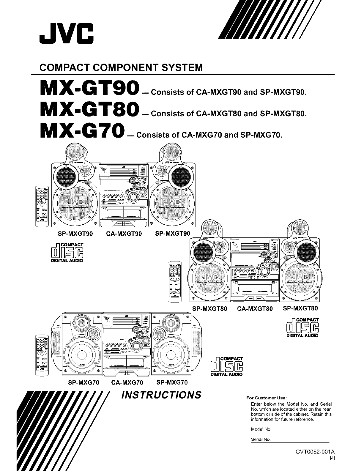
COMPACT COMPONENT SYSTEM
MX,,G T90_ consistsofCA-MXGT90andSP-MXGT90.
MX'G T80- ConsistsofCA-MXGT80andSP-MXGT80.
MXmG 70 -- Consists of CA-MXG70 and SP-MXG70.
SP-MXGT90
DIGITAL AUDIO
CA-MXGT90
SP-MXGT90 !
SP-MXGT80
DIGITAL AUDIO
CA-MXGT80 SP-MXGT80
DIGITAL AUDIO
SP-MXG70 CA-MXG70 SP-MXG70
INSTRUCTIONS
For Customer Use:
Enter" below the Model No. and Serial
No. which are located either on the rear,
bottom or side of the cabinet. Retain this
information for future reference.
Model No.
Serial No.
GVT0052-001A
[J]
Page 2

Warnings, Cautions and Others
Mises en garde, precautions et indications diverses
CAUTION: TO REDUCE THE RISK OF ELECTRIC SHOCK,
DO NOT REMOVE COVER (OR BACK)
NO USER SERVICEABLE PARTS INSIDE
REFER SERVICING TO QUALIFIED SERVICE PERSONNEL
The lightning flash with arrowhead symbol,
within an equilateral tdangle is intended to
alert the user to the presence of uninsulated
"dangerous voltage" within the product's
enclosure that may be of sufficient
magnitude to constitute a risk of electric
shock to persons.
The exclamation point within an equilateral
triangle is intended to alert the user to the
presence of important operating and
maintenance (servicing) instructions in the
literature accompanying the appliance,
WARNING: TO REDUCE THE RISK OF FIRE
OR ELECTRIC SHOCK, DO NOT EXPOSE
THIS APPLIANCE TO RAIN OR MOISTURE.
CAUTION
To reduce the risk of electdcal shocks, fire, etc.:
1. Do not remove screws, covers or cabinet.
2. Do not expose this appliance to rain or moisture.
ATTENTION
Afin d'6viter tout risque d'_lectrocution, d'incendie, etc.:
1. Ne pas enlever les vis ni Ies panneaux et ne pas ouvrir
le coffret de I'appareil.
2. Ne pas exposer I'appareil a Ia pluie ni a I'humidit&
For U.S.A.
This equipment has been tested and found to comply with the limits
for a Class B digital device, pursuant to part 15 of the FCC Rules.
These timits are designed to provide reasonable protection against
harmful interference in a residential installation.
This equipment generates, uses and can radiate radio frequency
energy and, if not installed and used in accordance with the
instructions, may cause harmful interference to radio
communications. However, there is no guarantee that interference
will not occur in a particular insta]lafion. If this equipment does cause
harmful interference to radio or television reception, which can be
determined by turning the equipment off and on, the user is
encouraged to try to correct the interference by one or more of the
following measures:
Reorient or relocate the receiving antenna.
Increase the separation between the equipment and receiver.
Connect the equipment into an outlet on a circuit different from that
to which the receiver is connected.
Consult the dealer or an experienced radio/TV technician for help.
For Canada/pour le Canada
CAUTION: TO PREVENT ELECTRIC SHOCK, MATCH WIDE
BLADE OF PLUG TO WIDE SLOT, FULLY INSERT.
ATTENTION: POUR EVITER LES CHOCS ELECTRIQUES,
INTRODUIRE LA LAME LA PLUS LARGE DE LA FICHE DANS
LA BORNE CORRESPONDANTE DE LA PRISE ET POUSSER
JUSQUAU FOND.
For Canada/pour le Canada
THiS DIGITAL APPARATUS DOES NOT EXCEED THE CLASS
B LIMITS FOR RADIO NOISE EMiSSiONS FROM DIGITAL
APPARATUS AS SET OUT IN THE INTERFERENCE-CAUSING
EQUIPMENT STANDARD ENTITLED "DIGITAL APPARATUS,"
ICES-gO3 OF THE DEPARTMENT OF COMMUNICATIONS.
CET APPAREIL NUMERIQUE RESPECTE LES LIMITES DE
BRUITS RADIOELECTRIQUES APPLICABLES AUX APPAREILS
NUMIRIQUES DE CLASSE B PRESCRITES DANS LA NORME
SUR LE MATERIEL BROUILLEUR:"APPAREILS NUMERIQUES",
NMB-O03 EDICTEE PAR LE MINISTRE DES
COMMUNICATIONS.
Caution- STANDBY/ON Oil button!
Disconnect the mains plug to shut the power offcompletely.
The STANDBY/ON (511 button in any position does not
disconnect the mains line. The power can be remote
controlled.
Attention -- Commutateur STANDBY/ON (._/I buttont
D6connecter Iafiche de secteur pour couper completement
Ie courant. Le commutateur STANDBY/ON (b/I ne coupe
jamais completement la ligne de secteur, quelle que soit sa
position. Le courant peut 6tre t_16command&
1. CLASS 1 LASER PRODUCT
2. DANGER: Invisible laser radiation when open and interlock
failed or defeated. Avoid direct exposure to beam.
3. CAUTION: Do not open the top cover. There are no user
serviceable parts inside the Unit; leave all servicing to
qualified service personnel.
1. PRODUIT LASER CLASSE 1
2. ATTENTION: Radiation laser invisible quand I'appareil est
ouvert ou que le verrouillage est en panne ou d_sactiv&
Eviter une exposition directe au rayon.
3. ATTENTION: Ne pas ouvrir le couvercle du dessus. I1n'y a
aucune piece utilisable a I'int_rieur. Laisser a un personnel
qualifi6 le soin de r6parer votre appareil.
-G-1 -
Page 3
t Instructions for safe use
(Statement in accordance with the UL standards)
1) Read Instructions--Read carefully this instructions for
your safe use before this appliance is installed, wire-
connected, and operated.
2) Retain Instructions -- For your future reference, retain
this instruction.
3) Follow Instructions -- Follow and obey all warnings,
cautions and instructions marked on this appliance and
this instruction.
4) Water and Moisture -- Do not expose this appliance to
rain, water and moisture, or operate it near water -- for
example near a bathtub, wash bowl, kitchen sink,
laundry tub, in a wet basement or near a swimming pool,
and the like.
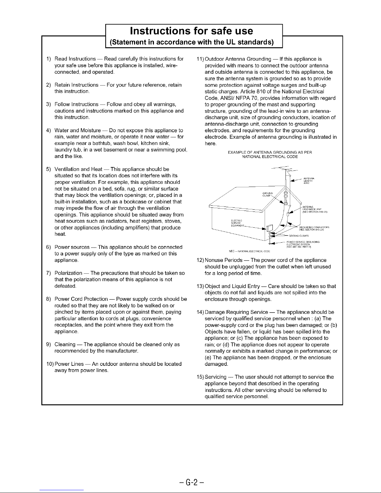
11)Outdoor Antenna Grounding -- If this appliance is
provided with means to connect the outdoor antenna
and outside antenna is connected to this appliance, be
sure the antenna system is grounded so as to provide
some protection against voltage surges and built-up
static charges. Article 810 of the National Electrical
Code, ANSI/NFPA 70, provides information with regard
to proper grounding of the mast and supporting
structure, grounding of the lead-in wire to an antenna-
discharge unit, size of grounding conductors, location of
antenna-discharge unit, connection to grounding
electrodes, and requirements for the grounding
electrode. Example of antenna grounding is illustrated in
here.
EXAMPLE OF ANTENNA GROUNDING AS PER
"_JATIONAL ELECTRICAL CODE
5) Ventilation and Heat-- This appliance should be
situated so that its location does not interfere with its
proper ventilation. For example, this appliance should
not be situated on a bed, sofa, rug, or similar surface
that may block the ventilation openings; or, placed in a
built-in installation, such as a bookcase or cabinet that
may impede the flow of air through the ventilation
openings. This appliance should be situated away from
heat sources such as radiators, heat registers, stoves,
or other appliances (including amplifiers) that produce
heat.
6) Power sources-- This appliance should be connected
to a power supply only of the type as marked on this
appliance.
7) Polarization -- The precautions that should be taken so
that the polarization means of this appliance is not
defeated.
8) Power Cord Protection -- Power supply cords should be
routed so that they are not likely to be walked on or
pinched by items placed upon or against them, paying
particular attention to cords at plugs, convenience
receptacles, and the point where they exit from the
appliance.
9) Cleaning -- The appliance should be cleaned only as
recommended by the manufacturer.
10) Power Lines -- An outdoor antenna should be located
away from power lines.
12) Nonuse Periods -- The power cord of the appliance
should be unplugged from the outlet when left unused
for a long period of time.
13) Object and Liquid Entry-- Care should be taken so that
objects do not fall and liquids are not spilled into the
enclosure through openings.
14) Damage Requiring Service -- The appliance should be
serviced by qualified service personnel when : (a) The
power-supply cord or the plug has been damaged; or (b)
Objects have fallen, or liquid has been spilled into the
appliance; or (c) The appliance has been exposed to
rain; or (d) The appliance does not appear to operate
normally or exhibits a marked change in performance; or
(e) The appliance has been dropped, or the enclosure
damaged.
15) Servicing -- The user should not attempt to service the
appliance beyond that described in the operating
instructions. All other servicing should be referred to
qualified service personnel.
-G-2-
Page 4
Introduction
We would like to thank you for purchasing one of our JVC products.
Before operating this unit, read this manual carefully and thoroughly to
obtain the best possible performance from your unit, and retain this manual
for future reference.
AboutThisManual
This manual is organized as follows:
• The manual mainly explains operations using the
buttons and controls on the unit. You can also use the
buttons on the remote control if they have the same or
similar names (or marks) as those on the unit.
If operation using the remote control is different from
that using the unit, it is then explained.
• Basic and common information thatis the same for many
functions is grouped in one place, and is not repeated in
each procedure. For instance, we do not repeat the
information about turning on/off the unit, setting the
volume, changing the sound effects, and others, which are
explained in the section "Common Operations" on pages 9
to 11.
• The following marks are used in this manual:
Gives you warnings and cautions to prevent
from damage or risk of fire/electric shock,
Also gives you information which is not good
for obtaining the best possible performance
from the unit.
Gi_es you information and hints you had better
know.
Precautions
Installation
• Install in a place which is level, dry and neither too hot nor
too cold between 5°C (41°F) and 35°C (95°F),
• Install the unit in a location with adequate ventilation to
prevent inlernal heat built-up in the unit,
• Leave sufficient distance between the unit and the TV.
• Keep the speakers away from the TV to avoid interference
with TV,
DO NOT install the unit in a location near heatsources, or in a place subject to direct sunlight,
excessive dust or vibration. I
Power sources
• When unplugging from the wall outlet, always pull the
plug, not the AC power cord.
,_ DO NOT handle the AC power cord with wet
hands.
Moisturecondensation
Moisture may condense on the lens inside the unit in the
following cases:
• After starting heating in the room
• in a damp room
• if the unit is brought directly from a cold to a warm place
Should this occur, the unit may malfunction. In this case,
leave the unit turned on for a few hours until the moisture
evaporates, unplug the AC power cord, and then plug it in
again,
Others
• Should any metallic object or liquid fall into the unit,
unplug the unit and consult your dealer before operating
any further.
• if you are not going to operate the unit for an extended
period of time, unplug the AC power cord from the wall
outlet,
DO NOT disassemble the unit since there are no
user serviceable parts inside.
If anything goes wrong, unplug the AC power cord and
consult your dealer.
-1-
Page 5
Contents
Location of the Buttons and Controls ....................... 3
Front Panel ................................................................. 3
Remote Control .......................................................... 5
Getting Started ............................................................ 6
Supplied Accessories .................................................. 6
Putting the Batleries into the Remote Control ........... 6
Connecling Antennas ................................................. 6
Connecling Speakers .................................................. 7
Connecling Other Equipment ..................................... 8
Canceling the display demonstration ........................ 8
Common Operations .................................................. 9
Turning On or Offthe Power ....................................... 9
Selting the Clock ........................................................ 9
Selecling the Sources ................................................... 9
Adjusting the Volume ............................................... 10
Reinforcing the Bass Sound ..................................... 10
Selecting the Sound Modes ...................................... 10
Creating Your Own Sound Mode
Manual Mode ................................................. 11
12
Listening to FM and AM Broadcasts ......................
Tuning in a Station ................................................... 12
Presetting Stations .................................................... 12
Tuning in a Preset Station ........................................ 12
Playing Back CDs (CD/CD-R/CD-RW) .................. 13
Loading CDs ............................................................ 13
Playing Back the Entire Discs
Continuous Play ............................................. 14
Basic CD Operations ................................................ 14
Programming the Playing Order of the Tracks
Program Play ................................................. 15
Playing at Random Random Play ....................... 16
Repeating Tracks or CDs Repeat Play ................ 16
Prohibiling Disc Ejection Tray Lock ................... 16
Playing Back Tapes ................................................... 17
Playing Back a Tape ................................................. 17
Locating the Beginning of a Song Music Scan ,,, 17
Recording .................................................................. 18
Recording a Tape on Deck B .................................... 18
Dubbing Tapes .......................................................... 19
CD Direct Recording ................................................. 19
Aulo Edit Recording .................................................. 20
Using the Timers ....................................................... 21
Using Daily Timer .................................................... 21
Using Recording Timer ............................................ 23
Using Sleep Timer .................................................... 24
Timer Priority ........................................................... 24
Maintenance .............................................................. 25
Troubleshooting ........................................................ 26
Specifications ............................................................. 27
i
%
7
2
Page 6
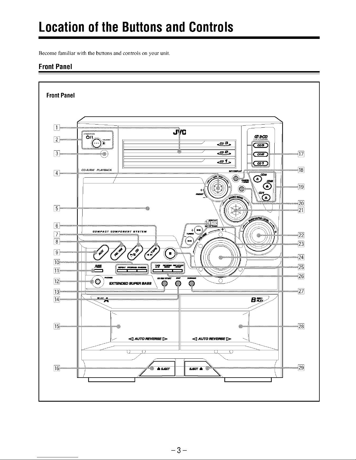
Locationofthe ButtonsandControls
Become familiar with the buttons and controls on your unit,
FrontPanel
FrontPanel
f
CD.R/RW pLAyBACK
<:_AUmR_'RSE[:>
J
<:]Au'm_WRSe _>
f
_3'CD
I I
-3-
Page 7
Continued
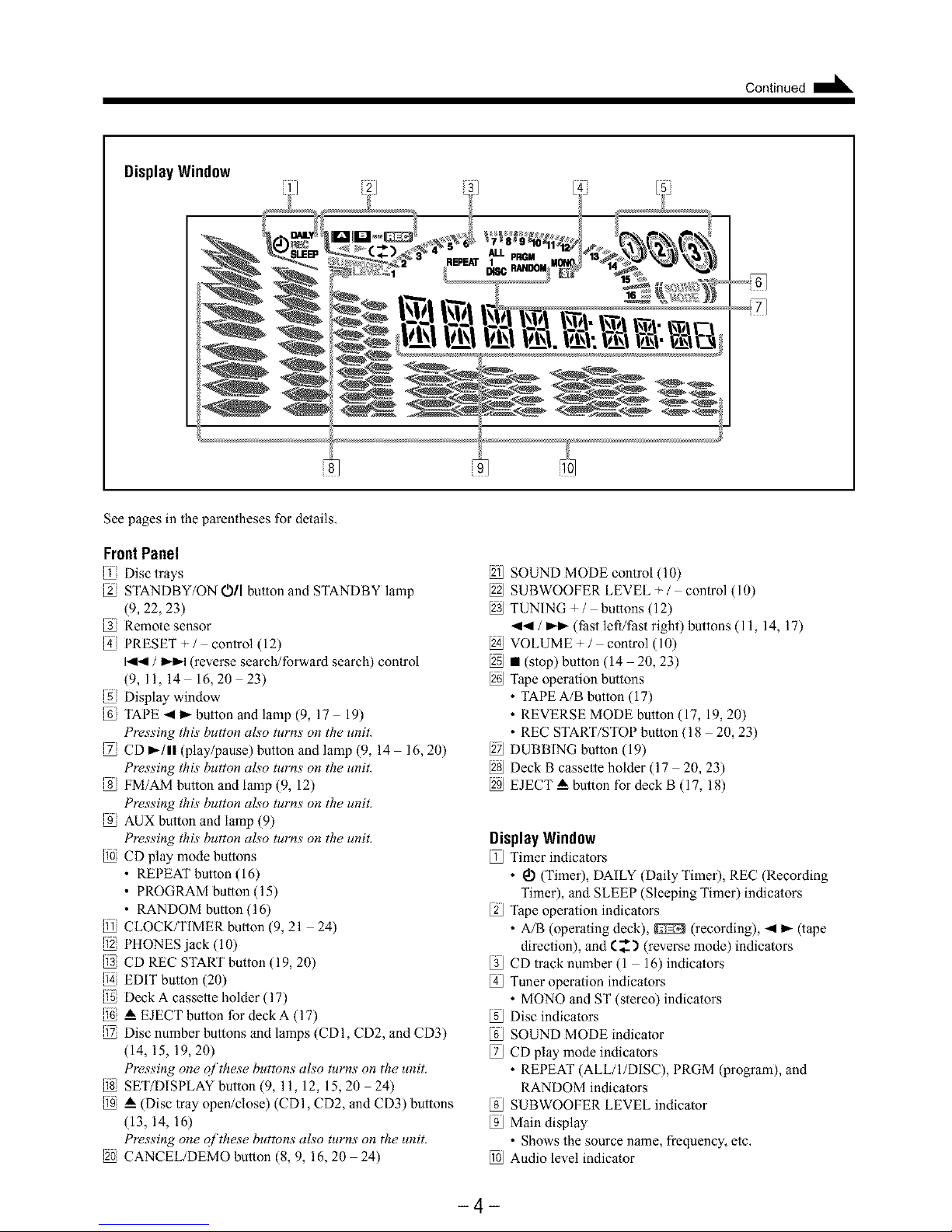
DisplayWindow
% %
See pages in the parentheses for details,
FrontPanel
Disc trays
STANDBY7ON OIl bulton and STANDBY lamp
(9, 22, 23)
Remote sensor
PRESET+/ control (12)
/ _ (reverse search/forward search) control
(9,11,14 16, 20 23)
Display window
TAPE 4 ),- button and lamp (9, 17 19)
Pressing this button also turns on tile unit.
CD _-/1! (play/pause) button and lamp (9, 14 16, 20)
Pressing this button also turns on the unit.
FM/AM butlon and lamp (9, 12)
Pressing this button also turns on the unit.
AUX button and lamp (9)
Pressing this button also turns on the unit.
CD play mode bultons
• REPEAT button (16)
• PROGRAM bulton (15)
• RANDOM bulton (16)
CLOCK/TIMER bulton (9,21 24)
@ PHONES jack (10)
CD REC START bulton (19, 20)
EDIT button (20)
Deck A cassetle holder (17)
A EJECT button for deck A (17)
Disc number butlons and lamps (CDI, CD2, and CD3)
(14, 15, 19, 20)
Pressing one of these buttons also turns on the unit.
SET/DISPLAY button (9, 11, 12, 15,20 24)
_ (Disc tray open/close) (CDI, CD2, and CD3) buttons
(13, 14, 16)
Pressing one of these buttons also turns on the unit.
CANCEL/DEMO button (8, 9, 16, 20 24)
SOUND MODE control (10)
SUBWOOFER LEVEL + / control (10)
TUNING +/ bultons (12)
-ql_ / _ (fast lefl/Past right) buttons (11, 14, 17)
VOLUME+/ control (10)
2_ • (stop) button (14 20, 23)
Tape operalion bultons
• TAPE A/B button (17)
• REVERSE MODE button (17, 19, 20)
• REC START/STOP bulton (18 20, 23)
DUBBING button (19)
Deck B cassette holder (17 20, 23)
EJECT _ button for deck B (17, 18)
DisplayWindow
112JTimer indicators
• _ (Timer), DAILY (Daily Timer), REC (Recording
Timer), and SLEEP (Sleeping Timer) indicators
Tape operalion indicators
• A/B (operaling deck), _ (recording), 4 _ (tape
direction), and (__'_ (reverse mode) indicators
[3J CD track number (1 16) indicators
4[_Tuner operalion indicators
• MONO and ST (stereo) indicators
Disc indicators
SOUND MODE indicator
[2J CD play mode indicators
• REPEAT (ALL/I/DISC), PRGM (program), and
RANDOM indicators
[sJ SUBWOOFER LEVEL indicator
[gJ Main display
• Shows the source name, frequency, etc,
l_J Audio level indicator
-4-
Page 8
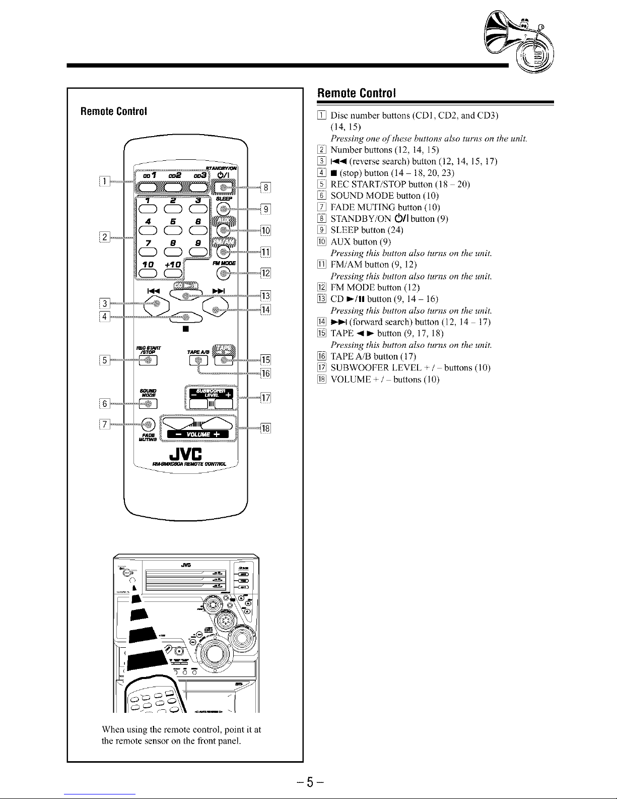
RemoteControl
f
JVn
When using the remote control, point it at
the remote sensor on the front panel.
RemoteControl
Disc number buttons (CDI, CD2, and CD3)
(14, 15)
Pressing one ojtbese buttons also turns on the unit,
Number buttons (12, 14, 15)
[3J _4 (reverse search)button (12, 14, 15, 17)
• (stop) button (14 18, 20, 23)
REC START/STOP bulton (18 20)
SOUND MODE button (10)
[ZJ FADE MUTING button (10)
[sJ STANDBY/ON (_/I bulton (9)
_J SLEEP button (24)
l_J AUX bulton (9)
Pressing this button also turns on the unit,
l_J FM/AM bulton (9, 12)
Pressing this button also turns on the unit,
1_ FM MODE button (12)
1_ CD _/11 bulton (9, 14 16)
Pressing this button also turns on the unit,
[] _ (forward search) button (12, 14 17)
TAPE _I _ button (9, 17, 18)
Pressing this button also turns on the unit,
1_ TAPE A/B bulton (17)
1_ SUBWOOFER LEVEL + / buttons (10)
1_ VOLUME + / bultons (10)
-5-
Page 9
GettingStarted onnt,nued"--=
SuppliedAccessories
Make sure that you have all the following items.
The number in the parentheses indicates the quantity of the
pieces supplied.
• AM loop antenna (1)
• FM antenna (1)
• Remote control (1)
• Batteries (2)
If anything is missing, consult your dealer immediately.
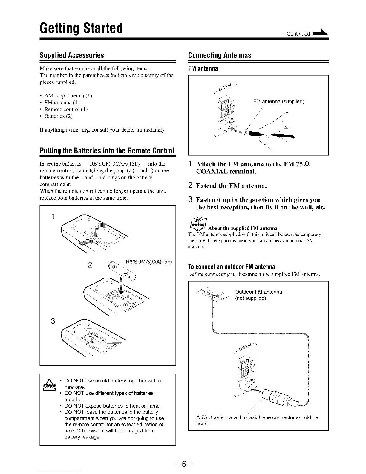
ConnectingAntennas
FMantenna
Puttingthe Batteries into the Remote Control
Insert the batteries R6(SUM-3)/AA(I 5F) into the
remote control, by matching the polarity (+ and ) on the
batteries with the + and markings on the battery
compartment.
When the remote control can no longer operate the unit,
replace both batteries at the same time.
3
2 _SUM-3)/AA(15F)
o _ _'_J
C+
• DO NOT use an old battery together with a
new one.
• DO NOT use different types of batteries
together.
• DO NOT expose batteries to heat or flame.
• DO NOT leave the batteries in the battery
compartment when you are not going to use
the remote control for an extended period of
time, Otherwise, it will be damaged from
battery leakage.
I Attach the FM antenna to the FM 75 _2
COAXIAL terminal.
2 Extend the FM antenna.
3 Fasten it up in the position which gives you
the best reception, then fix it on the wall, etc.
_About the supplied FM antenna
The FM antenna supplied with this unit can be used as temporary
measure. If reception is poor, you can connect an outdoor FM
antenna.
Toconnect an outdoor FMantenna
Before connecting it, disconnect the supplied FM antenna,
Outdoor FM antenna
(not supplied)
A 75 g_antenna with coaxial type connector should be
used.
-6-
Page 10
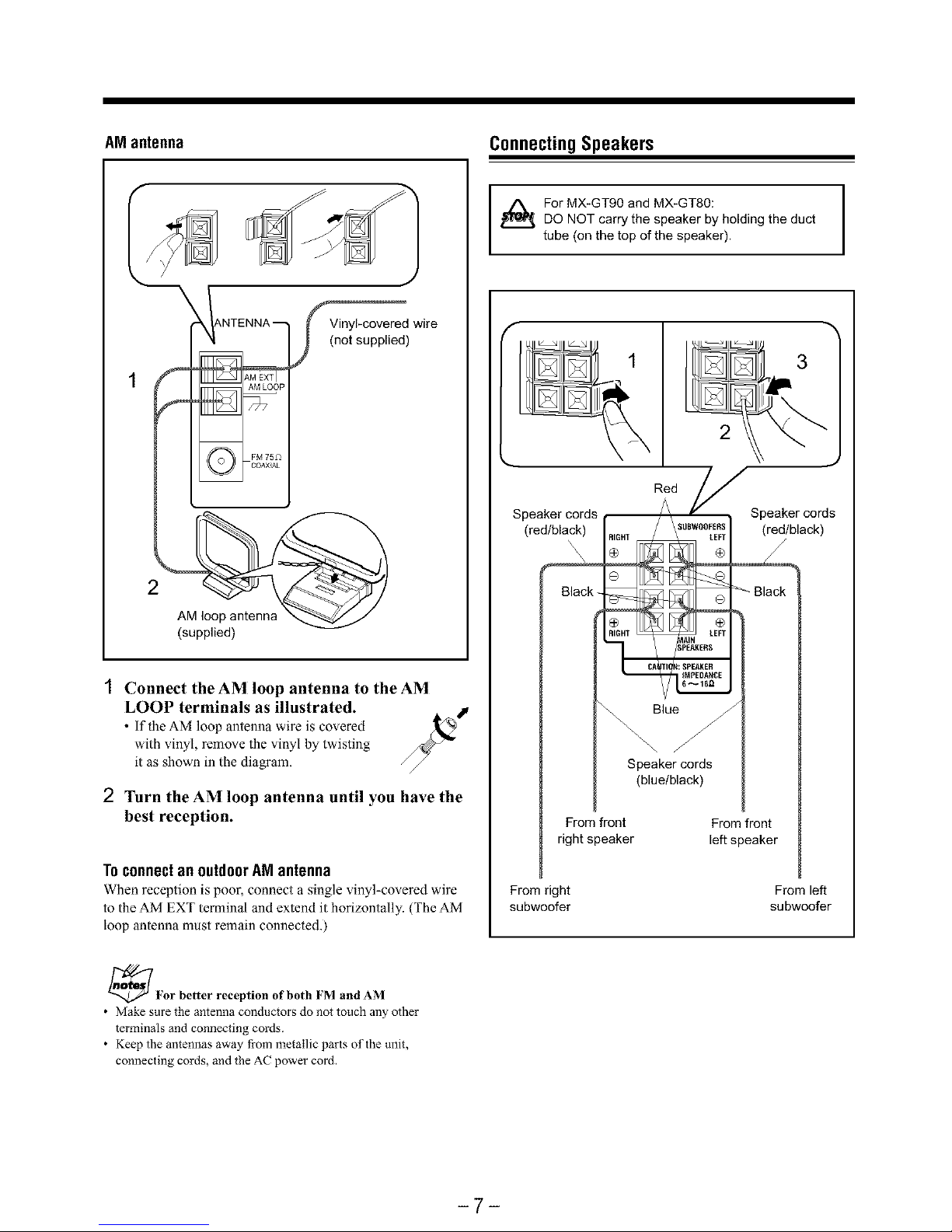
AM antenna ConnectingSpeakers
For MX-GT90 and MX-GT80:
DO NOT carry the speaker by holding the duct
tube (on the top of the speaker),
f
IANTENNA _
_d wire
(not supplied)
2
AM loop
(supplied)
Connect the AM loop antenna to the AM
LOOP terminals as illustrated.
• If the AM loop antenna wire is co\,ered
with vinyl, remove the vinyl by twisting
it as shown in the diagram.
2 Turn the AM loop antenna until you have the
best reception.
TOconnectan outdoorAM antenna
When reception is poor, connect a single vinyl-covered wire
to the AM EXT terminal and extend it horizontally. (The AM
hoop antenna must remain connected.)
3
2
Speaker cords Speaker cords
(red/black) (red/black)
\x\\
Blacl_
Blue
Speaker cords
(blue/black)
From front
right speaker
From front
left speaker
From right
subwoofer
From left
subwoofer
_For better reception of both FM and AM
• Make sure the antenna conductors do not touch any other
terminals and connecting cords.
• Keep the antennas away fi-om metallic parts of the unit,
connecting cords, and the AC power cord.
-7-
Page 11

1 Open the speaker terminals on the rear of the
unit.
2 Insert the end of the speaker cord into the
terminal.
Malch the polarity (colors) of the speaker lerminals: Red
(+) io red (+) and black @) to black ( ); Blue (+) to blue
(+) and black ( ) to black (),
3 Close the speaker terminals.
IMPORTANT: Use only speakers with the same speaker I
impedance as indicated by the speaker terminals on the
I
rear of the unit.
ConnectingOtherEquipment
You can connect both analog and digital equipment,
._- DO NOT connect any equipment while the power I
is on.
I
• DO NOT plug in any equipment until all
connections are complete.
Toconnectan analogcomponent
Be sure that the plugs of the audio cords are colored: White
plugs andjacks are for left audio signals, and red ones for
right audio signals,
Toconnectaudioequipmentwithan optical digital
inputterminal
You can record CD sound onto the connecled digital
equipment.
Before connecting the
other equipment,
remove the protective
plug from the terminal.
[
I Audio equipment with
' _ I an optical digital input
Tooptical digital input _
Connect an optical digital cord (not supplied) between the
optical digital input terminal on the other equipment and the
CD OPTICAL DIGITAL OUTPUT lerminal.
To audio output
Audio equipment
For playing the other equipment through this unit,
connect between the audio output jacks on the other
equipment and AUX jacks by using audio cords (not
supplied).
Now, you can plug the AC power cord.
When connecting the AC power cord into a wall outlet, the
unit automatically starts display demonstration,
IMPORTANT: Be sure to check all connections to be done
before plugging the AC power cord into a wall outlet.
Cancelingthe displaydemonstration
On the unit ONLY:
To cancel the display demonstration, press
CANCEL/DEMO until "DEMO OFF" appears
on the display.
_When you press other buttons
The display demonstration stops tempormily. It will start
automatically again (if no operation is done for 2 minutes) until you
cancel it by pressing CANCEL/DEMO.
To start the display demonstration manually
Press and hold CANCEL/DEMO again for more than 1
second.
-8-
Page 12

CommonOperations
TurningOnorOffthe Power
lb turn on the unit, press
STANDBY/ON O11 so that the
STANDBY lamp goes off,
| IF1
i:=t_F_El
'lb turn off the unit (on standby), press sr_,_By/o_
STANDBY/ON O/I again so that the #O/_sr_o, ,
STANDBYlamptightsup
F I-I 11-i"rt ,,
1Z11_lU,___ E
A little powerisalwaysconsumed even whiletheunitis on
standby.
'lb switch off the power supply completely, unplug the AC
power cord from the AC outlet,
When you unplug the AC power cord or if a power
hilure occurs
The clock is reset to "AM 12:00" right away, while the tuner preset
stations (see page 12) will be erased in a few days,
SettingtheClock
Before operating the unit any further, first set the clock built
in this unit,
You can set the clock whether the unit is on or off,
On the unit ONLY:
1Press CLOCK/TIMER.
The hour digits start flashing on the display,
2 Turn I_,_1 / _-_1 to adjust
the hour, then press
SET/DISPLAY.
The minute digits start flashing on the
display.
%
I_-I'.,I[_U_IRJIy
3 Turn I_1_1/ _-_1 to adjust the minute, then
press SET/DISPLAY.
I Ft t-
Tochecktheclocktime
Press and hold SET/DISPLAY while playing any source.
• Each time you press and hold the button, the source
indication and the clock time allernate on the display,
Toadjustthe clockagain
If you have adjusted the clock before, you need to press
CLOCK/TIMER repeatedly until the clock setting mode is
selected,
• Each time you press the button, the clock/timer setting
modes change as follows:
C DALLY-- ON TIME"_-RECq
Canceed_ ON T ME_
(The hour digits start flashing )
/_When you unplug power or a power
the AC cord if
_,L_ failure occurs
The clock loses the setting and is reset to "AM 12:00.' Yot need to
set the clock again.
SelectingtheSources
'lb listen to the FM/AM broadcasts, press FM/AM. (See
page 12.)
'lb play back CDs, press CD _-/ll. (See pages 13 16.)
'lb play back tapes, press TAPE 4 _. (See page 17.)
'lb select the external equipment as the source, press AUX.
When you press the play button for a particular source
(FM/AM, CD _-/ll, TAPE _1 _, and AUX), the unit turns on
(and the unit starts playing the source if it is ready
COMPU PLAY CONTROL),
if you want to correct the
hour after pressing
SET/DISPLAY, press
CANCEL/DEMO. The hour
digits start flashing again.
_About the audio Level indicator
All the audio level indicators light up when no signals come in.
-9-
Page 13

Continued I_
Adjustingthe Volume
You can adjust the xolume lexel only while the unit is turned
on. The volume lexel can be adjusted in 32 steps (VOL MIN,
VOL 01 VOL 30, and VOL MAX).
Turn VOLUME + / - clockwise (+) to
increase the volume or
counterclockwise (-) to decrease it.
BL
When using the remote control, press VOLUME + to increase
the volume or press VOLUME to decrease it.
_For private listening
Connect a pair of headphones to the PHONES jack. No sound
comes out of the speakers. Be sure to turn down the volume before
connecting or putting on headphones.
DO NOT turn off (on standby) the unit with the
volume set to an extremely high level; otherwise, a
sudden blast of sound can damage your hearing,
speakers and/or headphones when you turn on the
unit or start playing any source next time.
REMEMBER you cannot adjust the volume level
while the unit is on standby.
Toturndownthe volume level temporarily
Press FADE MUTING on the remote control,
The volume level gradually decreases to
"VOL M[N,"
'lb restore the sound, press the button again.
Reinforcingthe BassSound
You can select one of the 4 subwoofer levels. This function
only affects the playback sound, but does not affect your
recording. The subwoofer level can be adjusted in 4 sleps
LEVEL 1, LEVEL 2, LEVEL 3, and LEVEL 4 (MAX
LEVEL),
'lurn SUBWOOFER LEVEL +/-
clockwise (+) to increase the subwoofer
sound or counterclockwise (-) to
decrease it.
When using the remole control, press
SUBWOOFER LEVEL + to increase the subwoofer volume
or press SUBWOOFER LEVEL to decrease it.
SUBWOOFER indicator always lights up
when the unit is on.
SelectingtheSoundModes
You can select one of the 6 preset sound modes (3 surround
modes and 3 SEA Sound Effect Amplifier modes). This
function only affects the playback sound, but does not affect
your recording.
To select the sound modes, turn
SOUND MODE (or press
SOUND MODE on the remole control)
until the sound mode you want appears on
the display.
The SOUND MODE indicator
also lights up on the display.
o,
II t-t 11_i
II _LLLI__
• The sound modes change as follows:
[-_(DD.CLU B-_-_HALL -_-_STAD IUM_-,--ROCK -,,-1
ance CLUB) I'
r ,._ _ _ .-_ .-, POP
OFF * / t t
(Canceled) t
LMANUAL _- _- .,.I CLASSIC
3-,-_ MANUAL 2-,-_ MANUAL 1_,J
* When using the remote control, the sound mode changes in
only one way.
Surround modes **"
D.CLUB: Increases resonance and bass,
HALL: Adds depth and brilliance to the sound,
STADIUM: Adds clarity and spreads the sound, like in an
outdoor stadium.
SEA (Sound Effect Amplifier) modes:
ROCK: Boosts low and high frequency. Good for
acoustic music.
POP: Good for vocal music,
CLASSIC: Good for classical music.
Manual modes:
MANUAL 1/2/3:
Your individual mode slored in memory, See
"Creating Your Own Sound Mode Manual
Mode."
OFF: Cancels the sound mode. The SOUND MODE
indicator goes off from the display.
** Surround elements are added to the SEA elements to create a
being-there feeling in your room.
When one of these modes is selected, the SOUND MODE
While one of the SEA modes including manual modes (SEA
elements without surround elements) is selected, the SOUND
MODE indicator lights up as ............_2/:4_;_/;
-10-
Page 14

CreatingYourOwnSoundMode
-- ManualMode
You can change SEA pattern to suit your preference. These
changed setlings can be stored in the MANUAL 1,
MANUAL 2, and MANUAL 3 modes.
• There is a time limit in doing the following sleps, if the
setting is canceled before you finish, start from step 1
again.
On the unit ONLY:
1 Select one of the preset sound modes.
• If you want to add the surround elements in your
SEA pattern, select one of the surround modes
(D.CLUB, HALL, or STADIUM) before starling the
procedure below. (See "Selecting the Sound Modes" on
page 10,)
2 Press and hold SET/DISPLAY
until "SEA CONT" appears on
the display.
4Press SET/DISPLAY again.
5 Turn I_1_ / i,_l to select one
of the MANUAL 1, 2, and 3
modes into which you want
to store the SEA pattern.
6Press SET/DISPLAY again.
The SEA pattern you have created are stored into the
MANUAL mode selected in the abo_e step,
_ ¢l_ i_a _'_'_,_,_
_Z_X__ _
_._:: I_ I_I I,,I -r -_
/
Current level appears.
Adjust the SEA pattern.
1) Turn I_1_1 / _1 to select
the tYequency range to
adjust (LOW, MID,
HIGH).
2) Press _1_ or _ to
adjust the level (-3 to +3) of
the selected frequency
range.
3) Repeat steps 1) and 2) to
adjust the level of the other
frequency ranges.
+(
Touse yourownsound mode
Select MANUAL 1, MANUAL 2, or MANUAL 3 mode
when using the sound modes. See "Selecting the Sound
Modes" on page 10,
When you unplug the AC power cord or if a power
failure occurs
The setting will be erased in a few days. If this happens, set the
manual sound modes again.
-11 -
Page 15

Listeningto FMandAM Broadcasts
Tuningina Station
1Press FM/AM.
The unit automatically turns on and
tunes in the previously tuned station
(either FM or AM).
• Each time you press the button, the
band alternates between FM and AM,
2 Start searching tbr stations.
On the unit:
Press and hold TUNING +
or TUNING - tbr more than
1 second.
On the remote control:
Press and hold I_1_1 or I_1_1 _" '_
tbr more than 1 second. 0 %
The unit starts searching for stations
and stops when a station of sufficient
signal strength is tuned in,
• ifa program is broadcast in stereo, the ST (stereo)
indicator lights up,
'lb stop searching, press TUNING + or TUNING (or _ /
I,,II41on the remote control),
f_When you press I UNING or 1UNING - (or I_1 /
• , •q_ ,, •
1_14 on the remote control) briefly and repeatedly
The frequency changes step by step
Tochangethe FM receptionmode
When an FM stereo broadcast is hard to receive _'_
or noisy, press FM MODE on the remote
control so that the MONO indicator lights up
on the display, Reception improves,
'lb restore the stereo effect, press FM MODE again so that
the MONO indicator goes off, In this stereo mode, you can
hear stereo sounds when a program is broadcasted•
Presetting Stations
You can preset 30 FM and 15 AM stations.
In some cases, test frequencies have been already memorized
for the tuner since the factory examined the tuner preset
function before shipment, This is not a malfunction• You can
preset the stations you want into memory by following the
presetting method•
• There is a time limit in doing the following steps, if the
setting is canceled before you finish, start from step 1
again.
On the unit ONLY:
1 Tune in the station you want to preset.
• See "Tuning in a Station,"
The tuned station in step 1 is stored in the
preset number selected in step 3.
• Storing a new station on a used number erases the
previously stored one.
When you unplug the AC power cord or if a power
failure occurs
The preset stations will be erased in a few days. If this happens,
preset the stations again.
Tuningina PresetStation
1
2
Press FM/AM.
The unit automatically turns on and
tunes in the previously tuned station
(either FM or AM).
• Each time you press the button, the
band alternates between FM and AM.
Select a preset number.
On the unit:
Turn PRESET + / -.
On the remote control:
Press the number buttons.
Ex,: For preset number 5, press 5.
For preset number 15, press
+10 then 5,
For preset number 20, press
+10, then 10,
For preset number 25, press
+10, +10, then 5.
For preset number 30, press
+10, +10, then 10,
CD CD CD
4 6 8
CD CD CD
7 8 8
CD CD CD
CD
-12-
Page 16

PlayingBackCDs(CD/CD-R/CD-RW)
This unit has been designed to playback the following CDs:
• CD (Audio CD)
• CD-R (CD-Recordable)
• CD-RW (CD-ReWritable)
Continued use of irregular shape CDs
(heart-shape, octagonal, etc.) can damage
the System.
x©
General Notes
In general, you will have the best performance by keeping
your CDs and the mechanism clean,
• Store CDs in their cases, and keep them in cabinets or on
shelves.
• Keep the system's disc trays closed when not in use.
Whenplayinga CD-Ror CD-RW
User-edited CD-Rs (CD-Recordable) and CD-RWs
(CD-ReWritable) can be played back only if they are already
"finalized."
• You can play back your original CD-Rs or CD-RWs
recorded in music CD format, (However, they may not be
played back depending on their characteristics or recording
conditions.)
• Before playing back CD-Rs or CD-RWs, read their
instructions or cautions carefully.
• Some CD-Rs or CD-RWs may not be played back on this
unit because of their disc characteristics, damage or stain
on them, or the player's lens is dirty.
• CD-RWs may require a longer readout time, This is caused
by the fact that the reflectance of CD-RWs is lower than for
regular CDs,
Loading CDs
On the unit ONLY:
1Press A tbr the disc tray @cl_
(CDI, CD2, and CD3) you _
want to load a CD onto. _)
The unit automatically turns on and _...
the disc tray comes out.
2 Place a disc correctly on the circle of the disc
tray, with its label side up.
3
CORRECT INCORRECT
• When using a CDsingle (8 cm), place it on the inner
circle ofthe disc tray.
Press the same A you have ___c_
pressed in step I. _ _
The disc tray closes, and the ((A))
corresponding disc number lamp and _,r 1"'_
disc indicator light up on the display
(CDI, CD2, and CD3).
4 Repeat steps 1 to 3 to place other CDs.
_When loading more than one CD continuously
When you press _ for the next tray you want to place another CD
onto, the first disc tray automatically closes and then the next tray
comes out,
_About the disc indicators and disc number lamps
Each disc indicator corresponds to the disc tray of the same number.
Disc number
Disc indicator J
Disc marker
• The disc marker lights up for the disc number you have selected.
• The disc indicator flashes while the corresponding CD is being
played.
• The disc indicators goes off when the unit has detected that there
is no CD on the corresponding disc tray.
-13-
Page 17

Continued I_
Playing Backthe Entire Discs
-- Continuous Play
1 Load CDs.
2 Press one of the disc number
buttons (CDI, CD2, and
CD3) tbr the disc you want to
play.
CD play starts from the first track of
the selected disc and the disc number lamp starts flashing.
Tracks of the currently playing disc
(Track numbers exceeding 16 are not displayed.)
Track number Elapsed playing time
• Pressing CD I)-/ll instead of the disc number buttons
starts playing back ifa CD is on the trays,
• if no CD is placed on the selected disc tray, "'NO DISC"
appears on the display,
BasicCDOperations
While playing a CD, you can do the following operations.
ToexchangeCDsduringplaybackofanother
_ess A corresponding to a CD, not playing or selected
currently, to eject and exchange the CD.
If you exchange CDs during play, the current play will not
stop until all CDs you have exchanged are played.
Tostopplayfora moment
Press CD _/11.
While pausing, the elapsed playing time
flashes on the display.
To resume playing, press CD I_/11.
To go to another track
Turn 1,,(41/ _ before or during
playback (or press 1414/ _ on the
remote control).
• I..(_: Goes back to the beginning of
the current or previous tracks,
• I_._: Skips to the beginning of the
next or succeeding tracks,
]f you turn I'q4 / )q_l (or press I.(14 /
control) be|bre playing
You can change the tracks continuously
on the remote
'lb stop playing, press II.
'lb remove the disc, press A for the corresponding disc tray.
_CD playback sequence
When 3 CDs* are loaded on the disc trays, they are played in one of
the following sequences.
• When CDI is pressed: CD1 =:> CD2 =:> CD3 (then stops)
• When CD2 is pressed: CD2 =:> CD3 =:> CDI (then stops)
• When CD3 is pressed: CD3 =_5 CDI =_5 CD2 (then stops)
* When only 2 CDs are loaded, they are played in the same order,
but the disc tray without a CD is skipped.
Tolocatea particularpointin a track
During play, press and hold _14 or
(or 1414 / _1 on the remote control),
• 44 (or 141_1): Fast reverses the disc.
• _-_- (or)_).t): Fast forwards the disc,
Togoto anothertrackdirectlyusingthe number
buttons
_essing the number button(s) on the remote control before or
during play allows you to start playing the track number you
want,
Ex.: For track number 5, press 5, * • :)
For track number 15,press+lO, C:) C:D CD
For track number 20, press + 1O, 7 e •
lhen 10, _ _
For track number 32, press+10,+10,+10, then 2. ([D*°I_(_'_
-14-
Page 18

ProgrammingthePlayingOrderoftheTracks
-- ProgramPlay
You can arrange the order in which tracks play before you
start playing, You can program up to 32 tracks.
• To use Repeat play (see page 16) for Program play, press
REPEAT after starting Program play,
• There is a time limit in doing the following slops, if the
setting is canceled before you finish, start from step 2
again.
1Load CDs.
• if the current playing source is not the CD player, press
CO _-/ll, then • before going to the next step.
2 Press PROGRAM so that
"PROGRAM" appears on the
display.
The PRGM (program) indicator also lights up on the
display.
• Ifa program has been stored in memory, the program is
called up,
3 Press one of the disc number
buttons (CDI, CD2, and
CD3) to select the disc
number you want to play.
Track number
Discnumber
4 Select a track from the CD
selected in the above step.
On the unit:
Turn I_1 / l_ll_l to select the
track number and press
SET/DISPLAY.
On the remote control:
Press the number buttons.
• For how to use the number butlons,
see "To go to another track directly
using the number buttons" on page 14.
Program step number
E 13
4 5 B
7 B fl
CD
5 Program other tracks you want.
• To program tracks from the same disc, repeat step 4.
• To program tracks from a different disc, repeat steps 3
and 4.
I'l
O Press CD li_/ll.
The tracks are played in the order you
haxe programed.
To stop playing, press 1.
To exit from Program play mode, press PROGRAM again
before or after play, The PRGM (program) indicator goes off',
The program you ha_e made is stored in memory,
d¢
• If you try to program the 33rd track
"FULL" will appear on the display
• If your entry is ignored
You have tried to program a track from an empty tray, or a track
number that does not exist on the CD (for example, selecting track
14 on a CD that only has 12 tracks). Such entries are ignored.
• If the total playing time is 100 minutes or more
".... : ...2' will appear on the display.
Tochecktheprogramcontents
Before playing, you can check the
program conlents by pressing _ or 1_4
on the remote control.
• _ : Shows the programed tracks in
the programed order.
• I..I1_: Shows them in the reverse order,
0%
Tomodifythe program
Before or after playing, you can erase the last
programed tracks by pressing
CANCEL/DEMO,
• Each time you press the button, the programed
track shown on the display is erased from the
program,
• Ejecting a CD will also erase the track numbers
programmed from the ejecled CD,
To add tracks in the program before playing, simply select
the track numbers you want to add by following step 4 of the
programming procedure on page 15.
To erase the entire program before or after playing, press
1. "PROGRAM" appears on the display.
The program you have made will be erased, when
• You eject all the CDs.
• You unplug the AC power cord.
• A power failure occurs,
-15-
Page 19

Playingat Random-- RandomPlay RepeatingTracksorCDs-- RepeatPlay
The tracks of all loaded CDs will play at random.
• To use Repeat play for Random play, press REPEAT after
starting Random play,
1Load CDs.
• if the current playing source is not the CD player, press
CD _-/ll, then • before going to the next step.
Press RANDOM so that
"RANDOM" appears on the display.
The RANDOM indicator also lights up on the \"
display.
I
3 Press CD I_/ll.
The tracks are played at random.
Random play ends when all the tracks
areplayed once.
YOucan have all the CDs, the program or the individual track
currently playing repeat as many times as you like,
On the unit ONLY:
To repeat playing, press REPEAT during or _r
before play, To use Repeat play for Program
play and Random play, press the button after
starting playback,
• Each time you press the button, Repeat play mode changes
as follows, and the following indicator lights up on the
display:
E_REPEAT ALL _ REPEAT 1 DISC 'q
Canceled _ REPEAT 1
REPEAT ALL: Repeats all the tracks on all the CDs
(continuously or at random), or all the
tracks in the program,
REPEAT 1 DISC : Repeats all the tracks on one CD.
• REPEAT 1 DISC is not used for
Program play and Random play.
REPEAT 1: Repeats one track on one CD,
'lb skip the currently playing track, turn 1414/ _ to the
right (or press _1 on the remote control),
_Even if you turn 1_14 I*1_t to (or press _ on
/ the letT
the remote control)
You cannot go back to the previous tracks during Random play.
'lb stop playing, press !
• Random play also stops when one of the disc trays is
opened,
'l_ exit from Random play mode, press RANDOM again
before or after play.
To cancel Repeat play, press REPEAT repeatedly until the
REPEAT indicators go off from the display,
• Repeat play is also canceled when you select Programplay
or Random play,
Prohibiting Disc Ejection -- Tray Lock
YOUcan prohibit CD ejection from the unit and lock CDs,
• This operation is possible only when the source is the CD
player.
On the unit ONLY:
To prohibit disc ejection, press _ for
any disc tray while holding down •. (If
there is any disc tray opened, close it
first.)
"LOCKED" appears for a while, and the
loaded CDs are locked.
'1o cancel the prohibition and unlock
the CDs, press _ for any disc tray while
holding down !
"UNLOCKED" appears for a while, and
the loaded CDs are unlocked,
_lf you try to eject CDs
"LOCKED" appears to inform you that the Tray Lock is in use.
®
-16-
Page 20

PlayingBackTapes
You can play back type I, type II, and type IV tapes without
changing any settings.
PlayingBacka Tape
1 Press EJECT (A) tbr the deck you want to
use.
For Deck B
For Deck A
2 Put a cassette in with the exposed part of the
tape down.
3 Close the cassette holder gently.
If you put casseltes in both decks A and B, the last deck
you have put a cassetle into is selecled.
To select the other deck, press TAPE A/B
4Press TAPE -q _.
The tape play starts and the tape
direction indicator (_ or 4) starts
flashing slowly to indicate the tape
running direction.
• Each lime you press the bulton, the
tape direction changes.
I_ : plays the front side.
_1 : plays the reverse side,
• if no cassetle is inserted, "'NO TAPE" appears on the
display.
When the tape plays io the end, the deck automatically
stops if the Reverse Mode is not on, (See '"To play both
sides repeatedly Reverse Mode,")
'lb stop playing, press 1L ,,_
'Ib operate the other deck, press TAPE A/B,
then TAPE 4 _,
'lb fast-wind to the left or to the right, press _ or
(1414 or _ on the remote control) while the tape is not
running.
The tape direction indicator (4 or D,-) starts flashing quickly
on the display,
'lb remove the cassette, press A EJECT for deck A or
EJECT _ for deck B,
Toplaybothsidesrepeatedly-- ReverseMode
Reverse Mode works for both decks at the same time,
When it is in use, the tape automatically reverses at the end of
a side and the unit starts playing for the other side of the tape,
and repeats the same process,
'lo use Reverse Mode, press
REVERSE MODE so that the Reverse Mode
indicator on the display lights up like (._ ).
'1o cancel Reverse Mode, press the button
again so that the Reverse Mode indicator on the
display lights up like _.
When Reverse Mode is on with cassettes in both decks
A and B
After the reverse (_1) side of the tape finishes playing, the tape in the
other deck starts playing.
Locatingthe Beginningofa Song
-- MusicScan
YOUcan use Music Scan to locate the beginning of a song,
Music Scan searches for blank portions that usually separate
recorded songs, then plays the next song.
Tofindthe beginningofthe currentsong
During play, press _ or _ (141-qlor
on the remote control) in the opposite
direction Io the tape play,
The tape direction indicator of the opposite
direction to the tape play starts flashing
slowly,
Searching stops automatically at the beginning of the current
song, and the current song starts aulomatically.
Tofindthe beginningofthe nextsong
During play, press _ or _ (141-qlor
on the remote control) in the same
direction as the tape play.
The tape direction indicator of the same
direction as the tape play starts flashing
slowly and quickly alternately.
Searching stops automatically at the beginning of the next
song, and the next song starts aulomatically.
Music Scan works by detecting a 4-second long blank
between each song, so it will not work well in the
tbllowing cases
• No blank at the beginning of a song.
• Noise (often caused by much use or poor quality dubbing) which
fills the blank.
• Long, very soft passages or pauses in a song.
The use of the C-120 or thinner tape is not
recommended, since characteristic deterioration
may occur and this tape easily jams in the pinch-
rollers and the capstans.
-17-
Page 21

Recordi
Continued I_
IMPORTANT:
• It should be noted that it may be unlawful to re-record
pre-recorded tapes, records, or discs without the
consent of the owner of copyright in the sound or video
recording, broadcast or cable programme and in any
literary, dramatic, musical, or artistic embodied
therein.
• The recording level is automatically set correctly, so it is
not affected by the VOLUME, the SUBWOOFER LEVEL,
and the SOUND MODE controls. Thus, during recording
you can adjust the sound you are aclually listening to
without affecting the recording level.
• If recordings you have made have excessive noise or static,
the unit may be too close to a TV. increase the distance
between the TV and the unit.
• You can use lype I tape for recording.
Toprotectyourrecording
Cassettes have two small
tabs on the back to protect
from unexpected erasure or
re-recording.
To prolect your recording,
remove these tabs.
To re-record on a protected tape, co_er the holes with
adhesi_ e tape,
Tokeepthe bestrecordingandplaybacksoundquality
if the heads, capstans, and pinch rollers of the cassetle decks
become dirty, the following will occur:
• impaired sound quality
• Discontinuous sound
• Fading
• incomplete erasure
• Difficully in recording
*lbclean the heads, capstans, and pinch rollers
Use a cotton swab moistened with alcohol.
Pinch rollers
Capstans
Heads
*lb demagnetize the heads
Turn off the unit, and use a head demagnetizer (ax ailable at
electronics and audio shops).
Recordinga TapeonDeckB
1Press EJECT A tbr the deck B.
2
3
4
5
6
Put a recordable cassette into deck B.
Close the cassette holder gently.
Check the tape direction of deck B.
• If the tape direction is not correct, press TAPE 4 D.-
twice then • to change the tape direction.
Start playing the source -- FM, AM, CD
player, deck A, or auxiliary equipment
connected to AUX jacks.
• When the source is CD, you can also use CD Direct
Recording (see page 19) and Aulo Edit Recording (see
page 20).
• When the source is deck A, you can also use the
dubbing method (see "Dubbing Tapes" on page 19).
Start recording. ,,_,T,_-
/IDTCP
On the unit:
Press REC START/STOP.
On the remote control:
Press and hold REC START/STOP ,_m,,
tbr more than 1 second.
The _ (recording) indicator lights up on
the display and recording starts,
• If no cassette is inserted, "NO TAPE" appears on the
display, If a protected tape is inserted, "NO REC"
appears on the display.
To stop recording immediately, press •,
To remove the cassette, press EJECT A for deck B,
-18-
Page 22

Torecordonbothsides-- ReverseMode
Press REVERSE MODE so that the Reverse
Mode indicator lights up like (__), _:_
\-
• When using the Reverse Mode for recording,
start recording in the forward (D,-)direction
first, Otherwise, recording will stop when recording is done
only on one side (reverse) of the tape,
'lb cancel Reverse Mode, press the button again so that the
Reverse Mode indicator lights up like "*
DubbingTapes
You can record from one tape to another.
On the unit ONLY:
1 Press TAPE 411_, then m.
2 Put the source cassette in deck A, and a
recordable cassette into deck B.
• Put the cassettes in both decks so that the tapes will run
in the forward (D,-)direction,
m
3 Press DUBBING.
The _ (recording) indicator lights up on
the display and dubbing starts,
\-
CDDirectRecording
Ex erything on the CD goes onto the tape in the order it is on
the CD, or according to the order you ha_e made for Program
play.
On the unit ONLY:
1 Put a recordable cassette into deck B.
2 Load CDs.
3
4
Press one of the disc
number buttons (CDI,
CD2, and CD3) to select
the disc, then m.
• If you want to make a program, perform steps 2 Io 5 on
page 15. After making a program, go to the next step,
Press CD REC START. _,_srAnr
"CD REC" appears, and the _ QcX%.
(recording) indicator lights up on the
\-,
display.
Deck B starts recording and the CD player starts playing.
When the recording is done, "CD REC FINISHED"
appears on the display, and the CD player and deck B
stop,
'1o stop recording, press REC START/STOP _,,_r
or •, So that a 4-second blank portion is
created on the recording tape. (Remember a 4-
second blank is important when using Music
Scan see page 17.)
'lb stop dubbing, press • so that both decks (A and B) stop,
Torecordonbothsides-- ReverseMode
Press REVERSE MODE so that the Reverse
Mode indicator lights up like (__),
\"
'lb cancel Reverse Mode, press the button
again so that the Reverse Mode indicator
lights up like __,
Torecordonbothsides-- ReverseMode
R_
Press REVERSE MODE so that the Reverse t_
Mode indicator lights up like (__).
\-
• When using the Reverse Mode for CD Direct
Recording, start recording in the forward (_,-)
direction first, When the tape reaches its end while
recording a song in the forward direction (_), the last song
will be re-recorded at the beginning of the reverse side (-ql),
if you start recording on the reverse side (,91), recording
will stop when recording is done only on one side (reverse)
of the tape,
'1o cancel Reverse Mode, press the button again so that the
Reverse Mode indicator lights up like __.
-19-
Page 23

Auto Edit Recording
By using Auto Edit Recording, you can record the CD tracks
to fit the tape. Auto Edit Recording makes a program by
selecting the CD tracks in numerical order. However, to
prevent the end of the last track on the front side from being
cut off; the last track is selected so as to fit on the remaining
tape length.
4Press SET/DISPLAY. .rr,_n_az
• Each time you press the button, the tracks to
be recorded on the front side ("SIDE-A")
and on the reverse side ("SIDE-B") alternate,
Tracks to be recorded on the
reverse side (SIDE-B) appear.
On the unit ONLY:
1Load CDs.
• If the current playing source is not the CD player, press
CD _-/1|, then • before going to the next step.
2 Press EDIT.
3Press the disc number
button (CDI, CD2, and
CD3) tbr the disc you want
to record from.
"T
,FtF,E-
The optimum tape length for the disc appears.
To change the tape length manually
If the tape length selected is not satisfactory, you can
change the tape length by turning I..I1_/ _ on the unit.
You can select the tape length among the following
40, 46, 50, 54, 60, 64, 70, 74, 80, 84, and 90.
Put a recordable cassette of appropriate
length into deck B.
6Press REVERSE MODE so that _
the Reverse Mode indicator lights
up like c:).
\-
• Without turning on lhe Rexerse Mode
(¢_)), recording will stop when the front
side of the tape is recorded.
/Press CD REC START.
co IL_c _
"TAPE SIDE-A STAND-BY" appears,
and the _ (recording) indicator lights
up on the display.
Deck B starts recording then, about 10 seconds later, the
CD player starts playing.
When the recording is done, "CD REC FINISHED"
appears on the display, and the CD player and deck B
stop.
• lfa tape has not been rewound, deck B will rewind the
tape before it starts recording.
• A 10-second blank portion is automatically created at
the beginning of each side of the tape.
To stop during Auto Edit Recording
Press REC START/STOP or •. So that a 4-second blank
portion is created on the recording tape. (Remember a 4-
second blank is important when using Music Scan see
page 17.)
To cancel Auto Edit Recording
Press CANCEL/DEMO or • before or after play.
-20-
Page 24

UsingtheTimers
There are three timers available Daily Timer, Recording
Timer, and Sleep Timer,
Before using the timers, you need to set the clock built in the
unit, (See page 9.)
UsingDailyTimer
With Daily Timer, you can wake to your favorite music or
radio program. You can set the timer whether the unit is on or
of£
HowDaily Timeractuallyworks
The unit aulomatically turns on, set the volume level to the
preset level, and starts playing the specified source when the
on-time comes (the _ indicator ffashes just before the on-
time, and continues flashing while the timer is operating),
Then, when the off-time comes ("OFF" ffashes just before the
off-time), the unit automatically turns off (on standby),
The Daily timer works everyday automatically.
if you do not want to use the Daily timer, turn offthe Daily
timer, (See "To turn on or offDaily Timer after its selting is
done" on page 22,)
The timer setting remains in memory until you change it,
• There is a time limit in doing the following sleps, if the
setting is canceled before you finish, start from step 1
again.
• To correct a mis-entry while selting the timer, press
CANCEL/DEMO,
Before you start...
• When using the tuner as the source toplay
Make sure to select a desired station.
• When using a CD as the source to play
Make sure there is a CD on the selected disc number
tray.
• When using a tape as the source to play
Make sure that a tape is in the deck whose deck
indicator (A or B) is lit on the display,
Make sure that the tape direction is correct,
• When using the external component as the source to
pl.y
Set the timer equipped on the external component at
the same time.
On the unit ONLY:
1 Press CLOCK/TIMER repeatedly
until "DAILY" appears on the
display.
_) indicator lights up and DAILY (Daily
Timer) indicator also starts flashing on the
display,
3t- ; L ','
• Each time you press the button, the timer selting modes
change as follows:
_Bi ON TIME"_'RECq
c,ock--O.
setting
(See page 9)
Press CLOCK/TIMER again.
"ON TIME" appears for 2 seconds, then the
unit enters on-time setting mode,
\-
3Set the on-time you want the unit to turn on
at.
1) Turn 1,9141/ _ to set the hour,
then press SET/DISPLAY.
2) Turn 1,4141/ _ to set the minute,
then press SET/DISPLAY.
"OFF TIME" appears for 2
seconds on the display, then the
unit enlers off:time setting mode,
4 Set the oil:time you want the
unit to turn off (on standby)
at.
1) Turn I..*1_/ _ to set the hour, then press
SET/DISPLAY,
2) Turn I..(14/ _ to set the minute, then press
SET/DISPLAY,
The unit enlers source selecting mode.
_Z_E_Iq.Ay
-21 -
Page 25

Continued I_
5 Turn I_1_ / _l_l to select the source to play,
then press SET/DISPLAY.
• The source changes as follows:
ET x ERjT A--f'ju R
TUNER FM: tunes into a specified preset FM station,
"-* go to step 6.
TUNER AM: tunes into a specified preset AM station,
"-* go to step 6.
- CD - -: plays a disc from a specified track of a
specified disc. _ go to step 6.
TAPE: plays a tape in deck A or B,
-'* go to step 7.
AUX: plays an external source, --_ go to step 7.
6 When selecting "TUNER FM" or "TUNER
AM"
Turn la4 / _ to select the preset station number, then
press SET/DISPLAY.
The unit enters volume setting mode.
When selecting "- CD - -"
1) Turn I.,1141/ _ to select the disc number, then press
SET/DISPLAY,
2) Turn I.,11_/ _ to set the track number, then press
SET/DISPLAY,
The unit enters volume setting mode,
7 Turn laa / I_l_l to set the
volume level.
• The _olume level changes as follows: +l[-[ ((_ '_//_'1/
9 Press STANDBY/ON O/I to s_TJ°_
I_
turn off the unit (on standby) _
if you have set the Daily Timer _
with the unit turned on.
_lf the unit is turned on when the on-time comes
Daily Timer does not work.
Even if you unplug the AC power cord or if a power
failure occurs
Once you set the timer, the timer setting may remain stored in
memory in a few days. In this case, check whether the timer setting
still remains or not.
Toturnon or off DailyTimerafter itssettingis done
l
2
Press CLOCK/TIMER repeatedly until
,,mtm
"DALLY" appears on the display.
'1o turn off the Daily 'rimer, press
CANCEL/DEMO.
_) indicator and the DAILY (Daily Timer) _,mm
indicator go off from the display ("OFF" _
appears for a while),
The Daily Timer is canceled, but the
setting for the Daily Timer remains in
memory.
To turn on the Daily Timer, press
SE'ITDISPLAY.
_) indicator and the DALLY (Daily Timer)
indicator light up on the display, The
settings you have done are shown on the
display in sequence for your confirmation,
tw'rADiflit_.Ay
• If you select" VOL ," the xolume is set to the last
level when the unit has been turned oft:
8 Press SET/DISPLAY to complete
the Daily Timer setting.
The DAILY (Daily Timer) indicator slops
flashing and remains lit. The settings you
have done are shown on the display in
sequence.
-22-
Page 26

UsingRecordingTimer
With Recording Timer, you can make a tape of a radio
broadcast automatically. You can set the timer whether the
system is on or off',
HowRecordingTimer actuallyworks
The unit automatically turns on, tunes into dae specified
station, sets lhe volume level to "MIN," and starts recording
when the on-fime comes (the _ indicator flashes just before
the on-time, and conlinues flashing while the timer is
operating), Then, when the off-time comes ("OFF" appears
just before the oft-time), the unit automatically turns off (on
standby).
The timer setting remains in memory until you change it,
• There is a time limit in doing the following sleps, if the
setting is canceled before you finish, start from step 1
again.
• To correct a mis-entry while selting the timer, press
CANCEL/DEMO,
On the unit ONLY:
1Put a recordable cassette into deck B.
2 Press CLOCK/TIMER repeatedly
until "REC" appears on the
display.
The REC (Recording Timer) indicator also
starts flashing on the display.
P,E,'-_
• Each time you press the bulton, the timer setting modes
change as follows:
o,eo0-
setting
(See page 9)
3Press CLOCK/TIMER again.
"ON TIME" appears for 2 seconds then the
unit enters on-time setting mode,
4 Set the on-time you want the
unit to turn on at.
1) Turn 141_1/ _t to set the hour,
then press SET/DISPLAY,
2) Turn t_l_l / _ to set the minute,
then press SET/DISPLAY,
"OFF TIME" appears for 2
seconds, then the unit enters off'-
time setting mode.
5 Set the oil:time you want the
unit to turn off(on standby) at.
1) Turn 141_1/ _t to set the hour, then press
SET/DISPLAY,
2) Turn 141_1/ _t to set the mintue, then press
SET/DISPLAY,
The unit enters preset station selecting mode.
8_'/DIIDL4 y
6Select the preset station.
1) Turn 1414/ _ to select the band ("TUNER FM" or
"TUNER AM"), then press SET/DISPLAY.
2) Turn 141_1/ _ to select a preset channel number,
then press SET/DISPLAY,
The REC (Recording Timer) indicator stops flashing
and remains lit. The settings you have done are shown
on the display in sequence.
7 Press STANDBY/ON O/I to sT_By_o_
turn off the unit (on standby) O/_o_,--
if necessary.
\-
_lf you want to listen to another source while recording
Press REC START/STOP or • to stop recording. Without stopping
it, you cannot change the source.
Even if you unplug the AC power cord or if a power
failure occurs
Once you set the timer, the timer setting may remain stored in
memory in a few days. In this case, check whether the timer setting
still remains or not.
r-ltl
- 23 -
Page 27

Toturnon or offRecordingTimerafter itssettingis
done
1
2
CL_
Press CLOCK/TIMER repeatedly until /m_
"REC" appears on the display.
\-
'lb turn off the Recording Timer, press
CANCEL/DEMO.
The REC (Recording Timer) indicator goes
off from the display,
The Recording Timer is canceled, but the
setting for the Recording Timer remains in
memory,
'lo turn on the Recording Timer, press
SET/DISPLAY.
The REC (Recording Timer) indicator lights
up on the display, The settings you have done
are shown on the display in sequence Foryour
confirmation,
%
S_-r/DmPI.A ¥
UsingSleepTimer
With Sleep Timer, you can fall asleep to music,
You can set Sleep Timer only while the unit is turned on,
HowSleepTimer actuallyworks
The unit automatically turns off after the specified time
length passes.
On the remote control ONLY:
1Press SLEEP.
f-N
The time length until the shut-off time k_
appears and the SLEEP indicator starts
\"
flashing on the display.
• Each time you press the button, the time length changes
as Follows:
CLEEP10 "_SLE EP20 "_SLE EP30 "_SLE EP60 "]
Canceled _ SLEEP120 _ SLEEP90
TimerPriority
Since each timer can be set separately, you may wonder what
happens if the setting For these timers oxerlaps,
Here are examples.
Recording Timer has priority over Daily Timer and Sleep
Timer.
• if Daily Timer is set to come on while Recording Timer is
operating, Daily Timer will not come on at all.
AM 6:00 6:30 7:00 7:30
I I I I
Recording Timer L j I
I I I I
Daily Timer i
I
• If Recording Timer is set to come on while Sleep Timer is
operating, Sleep Timer will not work (the SLEEP indicator
does not go off),
PM 9:00 9:30 10:00 10:30
I I I I
Recording Timer i I ] i
I I I I
Sleep Timer i
I
not work.
2 Wait tbr about 5 seconds alter specifying the
time length.
The SLEEP indicator stops flashing and remains lit.
'lb check the remaining time until the shut-offtime, press
)
SLEEI once so that the remaining time until the shut-ofFtime
appears for about 5 seconds.
'lb change the shut-off time, press SLEEP repeatedly until
the desired time length appears on the display.
'lb cancel the setting, press SLEEP repeatedly unitil the
SLEEP indicator goes off5
• Sleep Timer is also canceled when you turn offthe unit,
- 24 -
Page 28

Maintenance
To get the best performance of the unit, keep your discs, tapes, and mechanism clean.
Handlingdiscs
fJ
• Remove the disc from its case by
holding it at the edge while pressing the
center hole lightly.
• Do not Iouch the shiny surPace of the
disc, or bend the disc.
• Put the disc back in its case after use to
prevent walping.
• Be careful not io scratch lhe surface of
the disc when placing it back in its
case.
• Avoid exposure to direct sunlight,
temperature extremes, and moisture.
'1o clean the disc
Wipe the disc with a soft cloth in a
straight line from center to edge,
I
DO NOT use any solvent-- such as conventional Irecord cleaner, spray, thinner, or benzine -- to
I
clean the disc.
Handlingcassettetapes
• If the tape is loose in its cassetle, take
up the slack by inserting a pencil in
one of the reels and rotating,
• If the tape is loose, it may get
strelched, cut, or caught in the
cassette.
• Be careful not to iouch the tape
surface.
• Avoid the following places to store the
tape:
In dusty places
In direct sunlight or heat
In moist areas
Near a magnet
Cleaningtheunit
Stains on the unit
Should be wiped offwith a soft cloth, if the unit is
heavily stained, wipe it with a cloth soaked in waler
diluted neutral delergent and wrung well, then wipe clean
with a dry cloth,
Since the unit may deteriorate in quality, become
damaged or get its paint peeled off, be careful about
the followings.
DO NOT wipe it with a hard cloth,
DO NOT wipe it strong.
DO NOT wipe it with thinner or benzine,
DO NOT apply any volatile substance such as
insecticides to it,
DO NOT allow any rubber or plastic to remain in
contact with it for a long time.
-25-
Page 29

Troubleshooting
if you are having a problem with your unit, check this list for a possible solution before calling for service.
if you cannot solve the problem from the hints given here, or the unit has been physically damaged, call a qualified person,
such as your dealer, for service.
Symptom
Unable to cancel the display demonstration.
No sound is heard.
Hard to listen to broadcasts because of
noise.
The disc sound is discontinuous.
The disc tray does not open or close.
The disc does not play.
The cassette holders cannot be opened.
Impossible to record.
Operations are disabled.
Unable to operate the unit from the remote
control.
Cause
Other buttons will pressed to cancel the
display demonstration.
Connections are incorrect or loose.
• Antennas are disconnected.
• The AM loop antenna is too close to the
unit.
• The FM antenna is not properly extended
and positioned.
The disc is scratched or dirty.
• The AC power cord is not plugged in.
• 'Frays are locked.
The disc is placed upside down.
Power supply from the AC power cord has
been cut off while the tape was running.
Small tabs on the back of the cassette are
removed.
The built-in microprocessor may
malfunction due to external electrical
interference.
• The path between the remote control and
the remote sensor on the unit is blocked.
• The batteries are exhausted.
Action
Press CANCEL/DEMO on the unit. (See
page 83
Check all connections and make
corrections. (See pages 6 to 8.)
• Reconnect the antennas correctly and
securely.
• Change the position and direction of the
AM loop antenna.
• Extend the FM antenna at the best
position.
Clean or replace the disc. (See above.)
• Plug the AC power cord.
• Unlock the trays, (See page 16.)
Place the disc with the label side up.
Turn on the unit.
Cover the holes with adhesive tape.
Unplug the AC power cord and then plug it
back in,
• Remove the obstruction,
• Replace the batteries,
-26-
Page 30

Specifications Des,gnspec, cotioosaresubjectto witho ,not,co,
MX-GT90
Amplifiersection-- CA-MXGT90
Output Power
SUBWOOFERS: 160 W per channel, min. RMS, driven into
6 £2 at 63 Hz with no more than 10% total
harmonic distortion.
MAIN SPEAKERS: 70 W per channel, rain. RMS, driven into
6 £2 at 1 kHz with no more than 10% total
harmonic distortion.
Audio input sensitivity/impedance
(at 1 kHz, measured at tape recording signal 300 mV)
AUX: 390 mV/50 k_
Digital output: CD OPTICAL DIGITAL OUTPUT
Signal wave length: 660 nm
Output level: ......15 dBm to 12 dBm
Speakers/Impedance:
SUBWOOFERS: 6 £2 16
MAIN SPEAKERS: 6 £2 16 £_
Tuner
FM tuning range: 87.5 MHz 108.0 MHz
AM tuning range: 530 kHz 1 710 kHz
CDplayer
CD capacity: 3 CDs
Dynamic range: 85 dB
Signabto_noise ratio: 90 dB
Wow and flutter: Immeasurable
Cassettedeck
F'requency response
Normal (type l): 50 Hz 14 000 Hz
Wow and flutter
0.15% (WRMS)
General
Power requirement: AC 120 V rL/, 60 Hz
Power consumption: 175 W/220 VA (at operation)
22 W (on standby)
Dimensions (approx.): 265 mmx 335 mm x 401 mm (W/WD)
(10 _k{,in. x 13 i/_ in. x 15 W., in.)
Mass (approx.): 10.0 kg (22A lbs)
Suppliedaccessories
See page 6.
Speakersection-- SP-MXGT90
Type: 3_Way 3_Speaker Bass&.eflex 'l_pe
Dual Giga-Tube Band-Pass Subwoofers
Speaker units: Subwoofer:
Woofer:
Tweeter:
Power handling capacity:
Subwoofer:
Main speaker:
Impedance: Subwoofer:
Main speaker:
F'requency range: Subwoofer:
Main speaker:
Sound pressure level: Subwoofer:
Dimensions (approx.):
Mass (approx.):
20 cm (7 % in.) cone xl
10 cm (3 _5/,,in.) cone xl
5 cm (2 in.) dome xl
160W
70 W
6£2
6£2
25 Hz 250 Hz
75 Hz- 32 000 Hz
77 dB/W.m
Main speaker: 84 dB/W.m
255 mmx 449 mmx 389 mm (WTWD)
(10 71_,in. x 17W_,in. x 15V_in.)
8.5 kg (18.8 lbs) each
MX-GT80
Amplifiersection-- CA-MXGTSO
Output Power
SUBWOOFERS: 130 W per channel, min. RMS, driven into
6 £2 at 63 Hz with no more than 10% total
harmonic distortion.
MAIN SPEAKERS: 55 W per channel, min. RMS, driven into
6 £2 at 1 kHz with no more than 10% total
harmonic distortion.
Audio input sensitivity/Impedance
(at 1 kHz, measured at tape recording signal 300 mV)
AUX: 390 mV750 kf_
Digital output: CD OPTICAL DIGITAL OUTPUT
Signal wave length: 660 nm
Output level: ......15 dBm to 12 dBm
Speakers/impedance:
SUBWOOFERS: 6 f_ 16 £2
MAIN SPEAKERS: 6 f_ 16 £2
Tuner
FM tuning range: 87.5 MHz 108.0 MHz
AM tuning range: 530 kHz 1 710 kHz
CDplayer
CD capacity: 3 CDs
Dynamic range: 85 dB
Signabtomoise ratio: 90 dB
Wow and flutter: Immeasurable
Cassettedeck
Frequency response
Normal (type I): 50 Hz 14 000 Hz
Wow and flutter
0.15% (WRMS)
General
Power requirement: AC 120 V F_, 60 Hz
Power consumption: 165 W/210 VA (at operation)
20 W (on standby)
Dimensions (approx.): 265 mmx 335 mm x 401 mm (W/H/D)
(l 0_/., in. x 13 I/4 in. x 1513/1_,in.)
Mass (approx.): 10.0 kg (22.1 lbs)
Suppliedaccessories
See page 6.
Speakersection-- SP-MXGT80
Type: 3_Way 3_Speaker Bass-Reflex Type
Dual Giga21_be Band-Pass Subwoofers
Speaker units: Subwoofer: 16 cm (65/E_, in.) cone xl
Woofer: l0 cm (3 W., in.) cone xl
Tweeter: 5 cm (2 in.) dome xl
Power handling capacity:
Subwoofer: 130 W
Main speaker: 55 W
Impedance: Subwoofer: 6
Main speaker: 6
Frequency range: Subwoofer: 30 Hz 120 Hz
Main speaker: 75 Hz 29 000 Hz
Sound pressure level: Subwoofer: 78 dB/W.m
Main speaker: 85 dB/W*m
Dimensions (approx.): 230 mmx 439 mm x 340 mm (W/H/D)
(9 I/l{,in. x 175/., in. x 13 _/l(, in.)
Mass (approx.): 7.2 kg (15.9 lbs) each
-27-
Page 31

MX-G70
Amplifiersection-- CA-MXG70
Output Power
SUBWOOFERS: 110 W per channel, min. RMS, driven into
6 £2 at 63 Hz with no more than 10% total
harmonic distortion.
MAIN SPEAKERS: 55 W per channel, rain. RMS, driven into
6 £2 at 1 kHz with no more than 10% total
harmonic distortion.
Audio input sensitivity/impedance
(at 1 kHz, measured at tape recording signal 300 mV)
AUX: 390 mV/50 kf_
Digital outpat: CD OPTICAL DIGITAL OUTPUT
Signal wave length: 660 nm
Outpat level: ......15 dBm to 12 dBm
Speakers/Impedance:
SUBWOOFERS: 6 £2 16 f_
MAIN SPEAKERS: 6 £2 16 f_
Tuner
FM tuning range: 87.5 MHz 108.0 MHz
AM tuning range: 530 kHz 1 710 kHz
CDplayer
CD capacity: 3 CDs
Dynamic range: 85 dB
Signal-to-noise ratio: 90 dB
Wow and flutter: Immeasurable
Cassettedeck
Frequency response
Normal (type l): 50 Hz 14 000 Hz
Wow and flutter
0.15% (WRMS)
General
Power requirement: AC 120 V rL/, 60 Hz
Power consumption: 160 W/205 VA (at operation)
20 W (on standby)
Dimensions (approx.): 265 mmx 335 mmx 401 mm (W/H/D)
(107k{. in. x 13 i/_ in. x 151 _/E_,in.)
Mass (approx.): 10.0 kg (22A lbs)
Suppliedaccessories
See page 6.
Speakersection-- SP-MXG70
Type: 3_Way 3_Speaker Bassq_.eflex type
Twin Hyper Power-Drive Subwoofer
Speaker units: Subwoofer:
Woofer:
Tweeter:
Power handling capacity:
Subwoofer:
Main speaker:
Impedance: Subwoofer:
Main speaker:
Frequency range: Subwoofer:
Main speaker:
Sound pressure level: Subwoofer:
Dimensions (approx.):
Mass (approx.):
14 cm (5 %(, in.) cone xl
16 cm (65k(, in.) cone xl
5 cm (2 in.) dome xl
ll0W
55W
6£2
6£2
29 Hz - 310 Hz
70Hz 29000Hz
76 dB/W,m
Main speaker: 87 dB/W*m
286 mm x 335 mmx 365 mm (WYH/D)
(115k_,in. x 13 I/4in. x 143/8 in.)
6.3 kg (13.9 lbs) each
-28-
Page 32

O0 't JVC SE VOE
HOW TO LOCATE YOUR JVC SERVICE CENTER
TOLL FREE : 1-800-537-5722
http://wwwjvcservice.com
Dear customer:
In order to receive the most satisfaction from your purchase, read the instruction booklet before operating the unit. In the event that repair
is necessary, or for the address nearest your location, please refer to the factory service center list below or within the Continental
United States, Cal! !-800-537-5722 for your authorized servicer. Remember to retain your Sill of Sale for Warranty Service.
_VC
JVC SERVICE & ENGINEERING
COMPANY OF AMERICA
DIVISION OF JVC AMERICAS CORP.
FACTORY SERVICE CENTER LOCATIONS
10 New Maple Avenue
Pine Brook, NJ 07058-9641
(973) 396-1000
5665 Corporate Avenue
Cypress, CA 90630-0024
(714) 229-8011
13 Cummings Park
Woburn, MA01801
(781) 376-9100
1500 Lakes Parkway
Lawrenceville, GA 30243-5857
(770) 339-2582
2969 Mapunapuna Place
Honolulu, HI 96819-2040
(808) 833-5828
8192 State Road 84
Davie, FL 33324
(954) 472-1960
705 Enterprise Street
Aurora, IL 60504-8149
(630) 851-7855
10700 Hammerly, Suite 110
Houston, TX 77043
(713) 935-9331
890 Dubuque Avenue
South San Francisco, CA 94080-1804
(650) 871-2666
Sophisticated electronic products may require occasional service. Just as quality is a keyword in the engineering and production of
the wide array of JVC products, service is the key to maintaining the high level of performance for which JVC is world famous. The
JVC service and engineering organization stands behind our products.
NATIONAL HEADQUARTERS
JVC SERVICE & ENGINEERING COMPANY OF AMERICA
DIVISION OF JVC AMERICAS CORP.
1700 Valley Road
Wayne, NJ 07470
If you ship the product • • °
Pack your JVC unit in the original carton or one of equivalent
size and strength. Enclose, with the unit, a letter stating the
problem or symptom that exists and also a copy of the
receipt or bil! ofsale you received when you purchased your
JVC unit. Print your home return address on the outside
and the inside of the carton. Send to the appropriate JVC
Factory Service Center as listed above.
Don't service it yourself.
CAUTION
To prevent electrical shock, do not open the cabinet. No user
serviceable parts inside.
Refer servicing to qualified service personnel
_CCESSORIES
To purchase accessories for your JVC product, you may contact your local JVC Dealer.
Or from the 48 Continental United States carl toil free : 800-882-2345
(1099)
Page 33

JVC AO0,O-
JVC COMPANY OF AMERICA warrants this product and all parts thereof, except as set forth below ONLY TO THE ORIGINAL
PURCHASER AT RETAIL to be FREE FROM DEFECTIVE MATERIAL AND WORKMANSHIP from the date of original retail
purchase for the period as shown below. ("The Warranty Period.")
* PARTS LABOR
1YR 1YR
. THIS LIMITED WARRANTY IS VALID ONLY IN THE FIFTY(50) UNITED STATES, THE DISTRICT OF COLUMBIA AND IN
COMMONWEALTH OF PUERTO RICO.
WHAT WE WILL DO:
If this product is found to be defective, JVC will repair or replace defective parts at no charge to the original owner. Such
repair and replacement services shall be rendered by JVC during normal business hours at JVC authorized service centers.
Parts used for replacement are warranted only for the remainder of the Warranty Period. All products and parts thereof may be
* brought to a JVC authorized service center on a carry-in basis except for Television sets having a screen size 28 inches and
above which are covered on an in-home basis.
. WHATYOU MUST DO FOR WARRANTY SERVICE:
Return your product to a JVC authorized service center with a copy of your bill of sale. For your nearest JVC authorized
service center, please call toll free: (800)537-5722.
If service is not available locally, box the product carefully, preferably in the original carton, and ship, insured, with a copy of
* your bill of sale plus and letter of explanation of the problem to the nearest JVC Factory Service Center, the name and location
of which will be given to you by the toll-free number.
If you have any questions concerning your JVC Product, please contact our Customer Relations Department.
WHAT IS NOT COVERED:
This limited warranty provided by JVC does not cover:
1. Products which have been subject to abuse, accident, alteration, modification, tampering, negligence, misuse, faulty
installation, lack of reasonable care, or if repaired or serviced by anyone other than a service facility authorized by JVC to
render such service, or if affixed to any attachment not provided with the products, or if the model number or seriai number
has been altered, tampered with, defaced or removed;
2. Initial installation and installation and removal for repair;
3. Operational adjustments covered in the Owner's Manual, normal maintenance, video and audio head cleaning;
4. Damage that occurs in shipment, due to act of God, and cosmetic damage;
* 5. Signal reception problems and failures due to line power surge;
* 6. Video Pick-up Tubes/CCD Image Sensor, Cartridge, Stylus(Needle) are covered for 90 days from the date of purchase;
. 7. Accessories;
8. Batteries (except the Rechargeable Batteries are covered for 90 days from the date of purchase);
There are no express warranties except as Iisted above.
* THE DURATION OF ANY IMPLIED WARRANTIES, INCLUDING THE IMPLIED WARRANTY OF MERCHANTABILITY, IS
LIMITED TO THE DURATION OF THE EXPRESS WARRANTY HEREIN.
JVC SHALL NOT BE LIABLE FOR THE LOSS OF USE OF THE PRODUCT, INCONVENIENCE, LOSS QR ANY OTHER
DAMAGES, WHETHER DIRECT, INCIDENTAL OR CONSEQUENTIAL (INCLUDING, WITHOUT LIMITATION, DAMAGE TO
TAPES, RECORDS OR DISCS) RESULTING FROM THE USE OF THIS PRODUCT, OR ARISING OUT OF ANY BREACH OF
THIS WARRANTY. ALL EXPRESS AND IMPLIED WARRANTIES, INCLUDING THE WARRANTIES OF MERCHANTABILITY
AND FITNESS FOR PARTICULAR PURPOSE, ARE LIMITED TO THE WARRANTY PERIOD SET FORTH ABOVE.
Some states do not allow the exclusion of incidental or consequential damages or limitations on how long an implied
warranty last, so these limitations or exclusions may not apply to you. This warranty gives you specific legal rights and you
may also have other rights which vary from state to state.
JVC COMPANY OF AMERICA
DIVISION OF JVC AMERICAS CORR
1700 Valley Road
Wayne, NJ 07470
REFURBISHED PRODUCTS CARRY A SEPARATE WARRANTY, THIS WARRANTY DOES NOT APPLY. FOR DETAILS OF
REFURBISHED PRO DUCT WARRANTY, PLEASE REFER TO THE REFURBISHED PRODUCT WARRANTY INFORMATION
PACKAGED WITH EACH REFURBISHED PRODUCT.
For customer use:
Enter below the Model No. and Serial No. which is located either on the rear, bottom or side of the cabinet. Retain this
information for future reference.
Model No.: Serial No.:
Purchase date: Name of dealer:
Page 34

/
JVC
VICTOR COMPANY OF JAPAN, LIMITED
(_EN _ 0101MWMMDWJEM
 Loading...