

Page 1
U
O
ON
SET
BD-X201M DVD RECORDER
DVD RECORDER
is a registered trademark owned by Victor Company of Japan, Limited
is a registered trademark in Japan, the U.S.A., the U.K. and other countries.
© 2005 Victor Company of Japan, Limited
Printed in Japan
LLT0073-001A
BD-X201M
OPERATE
AUDIO
CH1
CH2
PHONES REV
Thank you for purchasing this product. Before operating this
unit, please read the instructions carefully to ensure the best
possible performance.
For Customer Use :
Enter below the Serial No. which is located on the bottom
of the unit.
Retain this information for future reference.
Model No. BD-X201M
Serial No.
DOLBY DIGITAL
LPCMMPEG
STOP PLAY
INSTRUCTIONS
BUSY
OPEN/CLOSE
TOP
MENU MEN
PTI
DVD RECORDER
BD-X201M
TITLE
CHAPTER
FWD PAUSE REC
This instruction book is made from 100 % recycled paper.
LLT0073-001A
Page 2
IMPORTANT SAFEGUARDS
Safety Precautions
1. Read all of these instructions.
2. Save these instructions for later use.
3. All warnings on the product and in the operating instructions should be adhered to.
4. Unplug this appliance system from the wall outlet before cleaning. Do not use liquid cleaners or aerosol cleaners.
Use a damp cloth for cleaning.
5. Do not use attachments not recommended by the appliance manufacturer as they may cause hazards.
6. Do not use this appliance near water - for example, near a bathtub, washbowl, kitchen sink, or laundry tub, in a
wet basement, or near a swimming pool, etc.
7. Do not place this appliance on an unstable cart, stand, or table. The appliance may fall, causing
serious injury to a child or adult, and serious damage to the appliance.
Use only with a cart or stand recommended by the manufacturer, or sold with the appliance. Wall
or shelf mounting should follow the manufacturer’s instructions, and should use a mounting kit
approved by the manufacturer. An appliance and cart combination should be moved with care.
Quick stops, excessive force, and uneven surfaces may cause the appliance and cart combination
to overturn.
8. Slots and openings in the cabinet and the back or bottom are pro-vided for ventilation, and to insure reliable
operation of the appliance and to protect it from overheating, these openings must not be blocked or covered. The
openings should never be blocked by placing the appliance on a bed, sofa, rug, or other similar surface.
This appliance should never be placed near or over a radiator or heat register. This appliance should not be
placed in a built-in installation such as a bookcase unless proper ventilation is provided.
9. This appliance should be operated only from the type of power source indicated on the marking label. If you are
not sure of the type of power supplied to your home, consult your dealer or local power company. For appliance
designed to operate from battery power, refer to the operating instructions.
10. This appliance system is equipped with a 3-wire grounding type plug (a plug having a third (grounding) pin). This
plug will only fit into a grounding-type power outlet. This is a safety feature. If you are unable to insert the plug into
the outlet, contact your electrician to replace your obsolete outlet. Do not defeat the safety purpose of the grounding
plug.
11. For added protection for this product during a lightning storm, or when it is left unattended and unused for long
periods of time, unplug it from the wall outlet and disconnect the antenna or cable system. This will prevent
damage to the product due to lightning and power-line surges.
12. Do not allow anything to rest on the power cord. Do not locate this appliance where the cord will be abused by
persons walking on it.
PORTABLE CART WARNING
(symbol provided by RETAC)
S3125A
13. Follow all warnings and instructions marked on the appliance.
14. Do not overload wall outlets and extension cords as this can result in fire or electric shock.
15. Never push objects of any kind into this appliance through cabinet slots as they may touch dangerous voltage
points or short out parts that could result in a fire or electric shock. Never spill liquid of any kind on the appliance.
16. Do not attempt to service this appliance yourself as opening or removing covers may expose you to dangerous
voltage or other hazards. Refer all servicing to qualified service personnel.
17. Unplug this appliance from the wall outlet and refer servicing to qualified service personnel under the following
conditions:
a. When the power cord or plug is damaged or frayed.
b. If liquid has been spilled into the appliance.
c. If the appliance has been exposed to rain or water.
d. If the appliance does not operate normally by following the operating instructions. Adjust only those controls
that are covered by the operating instructions as improper adjustment of other controls may result in damage
and will often require extensive work by a qualified technician to restore the appliance to normal operation.
e. If the appliance has been dropped or the cabinet has been damaged.
f. When the appliance exhibits a distinct change in performance - this indicates a need for service.
18. When replacement parts are required, be sure the service technician has used replacement parts specified by the
manufacturer that have the same characteristics as the original part. Unauthorized substitutions may result in fire,
electric shock, or other hazards.
19. Upon completion of any service or repairs to this appliance, ask the service technician to perform routine safety
checks to determine that the appliance is in safe operating condition.
I
CAUTION
RISK OF ELECTRIC SHOCK
DO NOT OPEN
CAUTION: TO REDUCE THE RISK OF ELECTRIC SHOCK.
DO NOT REMOVE COVER (OR BACK).
NO USER-SERVICEABLE PARTS INSIDE.
REFER SERVICING TO QUALIFIED SERVICE PERSONNEL.
The lightning flash wish arrowhead symbol, within an equilateral
triangle is intended to alert the user to the presence of uninsulated
“dangerous voltage” within the product's enclosure that may be of
sufficient magnitude to constitute a risk of electric shock to persons.
The exclamation point within an equilateral triangle is intended to
alert the user to the presence of important operating and
maintenance (servicing) instructions in the literature accompanying
the appliance.
Changes or modifications not approved by JVC could void the user’s
authority to operate the equipment.
Information for USA
This device complies with Part 15 of the FCC Rules. Changes or
modifications not approved by JVC could void the user’s authority
to operate the equipment.
INFORMATION (FOR CANADA)
RENSEIGNEMENT (POUR CANADA)
• This Class B digital apparatus complies with Canadian ICES-003.
• Cet appareil numérique de la classe B est conforme à la norme
NMB-003 du Canada.
For North America
®
MEDICAL ELECTRICAL EQUIPMENT
WITH RESPECT TO ELECTRICAL SHOCK, FIRE,
MECHANICAL AND OTHER SPECIFIED HAZARDS
ONLY IN ACCORDANCE WITH
UL.60601-1, CAN/CSA C22.2 NO.601.1
56PA
ATTENTION
RISQUE D’ELECTROCUTION
NE PAS OUVRIR
ATTENTION: POUR EVITER TOUT RISQUE D’ELECTROCUTION
NE PAS OUVRIR LE BOITER.
ACCUNE PIECE INTERIEURE N’EST.
A REGLER PAR L’UTILISATEUR.
SE REFERER A UN AGENT QUALIFIE EN CAS DE PROBLEME.
Le symbole de l’éclair à l’intérieur d’un triangle équilatéral est
destiné à alerter l’utilisateur sur la présence d’une “tension
dangereuse” non isolée dans le boîtier du produit. Cette tension
est suffisante pour provoquer l’électrocution de personnes.
Le point d’exclamation à l’intérieur d’un triangle équilatéral est
destiné à alerter l’utilisateur sur la présence d’opérations
d’entretien importantes au sujet desquelles des renseignements
se trouvent dans le manuel d’instructions.
*Ces symboles ne sont utilisés qu’aux Etats-Unis.
REMARQUE:
La plaque d’identification (numéro de série) se trouve sur le
panneau arrière de l’appareil.
WARNING:
The battery used in this DVD recorder must be replaced by a
JVC authorized service dealer only.
WARNING:
Disporsal of product should follow National, State and Local Laws.
WARNING
It should be noted that it may be unlawful to re-record prerecorded tapes, records, or discs without the consent of the
owner of copyright in the sound or video recording, broadcast, or cable programme and in any literary, dramatic, musical or artistic work embodied therein.
WARNING
This apparatus is Medical Equipment.
Please make sure to use “hospital grade” power supply cord
specified by JVC.
Classifications
• Class : I
• Type : No applied parts
• Moisture Protection : Ordinary
• AP/APG Category : No
• Operation Mode : Continuous
II
Page 3

JVC Sales Office
JVC Professional Products Company
1700 Valley Road, Wayne, NJ 07470 USA HEADQUARTERS
tel: +1(973)317-5000
1. JVC Professional Europe Ltd.
Ullswater House, Kendal Avenue, London W3 0XA U.K.
tel: +44(020)8896-6000
2. JVC Professional Europe Ltd. Frankfurt, Germany
Gruener Weg 10, 61169 Friedberg / Hessen, Germany
tel: +49(06031)6050
3. JVC Professional Europe Ltd. Milano, Italy
Via Cassanese 224 Palazzo Tiepolo 20090 SegrateMilano Oltre, Italy
tel: +39(02)380501
4. JVC Professional Europe Ltd. Paris, France
1
Avenue Eiffel 78422 Carrieres-Sur-Seine Cedex, France
tel: +33(01)61 04 11 11
5. JVC Professional Europe Ltd. Barcelona, Spain
Ctra. De Rubi, 88 Ed. Can Castanyer 08190 Sant Cugat
del Valles (Barcelona) Spain
6. JVC Belgium S.A./N.V.
Rue de la Petite Ile 3, Klein-Eilandstraat, Bruxelles 1070
Brussel, Belgium
tel: +32(02)529-4211
7. JVC Professional Europe Ltd. Leiden, Nederland
JVC Plein, De Heyderweg 2, 2314 XZ Leiden, Nederland
tel: +31(071)545-3333
JVC Canada Inc.
21 Finchdene Square, Scarborough, Ontario, M1X 1A7 Canada
tel: +1(416)293-1311
8. JVC Professional Europe Ltd. Stockholm, Sweden
Veddestavagen 15,S-175 62 Jarfalla, Stockholm,
Sweden
tel: +46(08)7950400
9. JVC Professional Europe Ltd. Tonsberg, Norway
PO Box 2012PT, Wirgenes v5, Barkaker N-3103
Tonberg Norway
tel: +47(333)61600
10. JVC Professional Europe Ltd. Tastrup, Denmark
Helgeshoej Alle 30 DK-2630 Taastrup, Denmark
tel: +45(43)509000
11. Spitzer Electronics AG
Muehlemattstrasse 13, CH-4104 Oberwill Switzerland
tel: +41-61-405-1111
12. Oy Hedpro Ab
Lauttasaarentie 50 FIN-00200 Helsinki Finland
tel: +358-9-6828244
13. ILVI S.A
62,Piraeus Ave., 183 46 Moschato, Greek
tel: +30-210-4832855
Beilage
Dieses Gerät ist zum Gestelleinbau und zum Betreiben in unmittelbarer Nähe anderer Geräte und Vorrichtungen
geeignet.
Zur Erzielung einer optimalen Betriebsleistung und zur Einhaltung elektromagnetischer Schutzbestimmungen wird
die Verwendung von Kabeln empfohlen, die jeweils die angegebene Länge nicht überschreiten sollten:
Anschluss Kabeltyp Länge
AC IN Spezialkabe 2,5 m
Y/C Abgeschirmtes Kabel 3 m
VIDEO LINE Abgeschirmtes Kabel 3 m
AUDIO LINE Abgeschirmtes Kabel 3 m
REMOTE (9P) Abgeschirmtes Kabel 3 m
DV Abgeschirmtes Kabel 3 m
PHONES Abgeschirmtes Kabel 3 m
FOOT SWITCH Nichtabgeschirmtes Kabel 1,5 m
LAN (FOR SERVICE) Abgeschirmtes verdrilltes Doppelkabel 10 m
USB Abgeschirmtes Kabel 1,8 m
Der Einschaltstoßstrom für dieses Gerät beträgt 19 Ampere.
Vorsicht:
5 Bei der Einwirkung starker magnetischer oder elektromagnetischer Felder (z.B. Sendeantennen, Transformatoren,
Motoren etc.) können Bild- und Tonbeeinträchtigungen auftreten. In diesem Fall auf ausreichenden Abstand zur
möglichen Störquelle achten.
Supplement
This apparatus is designed for rack mounting or is used close to other apparatus.
In order to keep the best performance and furthermore for electromagnetic compatibility we recommend to use cables
not exceeding the following lengths:
Port Cable Length
AC IN Exclusive cable 2.5 meters
Y/C Shielded cable 3 meters
VIDEO LINE Shielded cable 3 meters
AUDIO LINE Shielded cable 3 meters
REMOTE (9P) Shielded cable 3 meters
DV Shielded cable 3 meters
PHONES Shielded cable 3 meters
FOOT SWITCH Non-shielded cable 1.5 meters
LAN (FOR SERVICE) Shielded Twist Pair cable 10 meters
USB Shielded cable 1.8 meters
The inrush current of this apparatus is 19 amperes.
Caution:
5 Where there are strong electromagnetic waves or magnetism, for example near a radio or TV transmitter, transformer,
motor, etc., the picture and sound may be disturbed. In such a case, please keep the apparatus away from the
sources of the disturbance.
III
Supplément
Ce matériel est conçu pour le montage en baie et peut être utilisé à proximité d’autres appareils.
Afin de maintenir la meilleure performance et notamment pour la compatibilité électromagnétique, nous recommandons
l’utilisation de câbles n’excédant pas les longueurs suivantes :
Port Câble Longueur
AC IN Câble exclusif 2,5 mètres
Y/C Câble blindé 3 mètres
VIDEO LINE Câble blindé 3 mètres
AUDIO LINE Câble blindé 3 mètres
REMOTE (9P) Câble blindé 3 mètres
DV Câble blindé 3 mètres
PHONES Câble blindé 3 mètres
FOOT SWITCH Câble non blindé 1,5 mètres
LAN (FOR SERVICE) Câble à paire torsadée blindé 10 mètres
USB Câble blindé 1,8 mètres
L’appel de courant de cet appareil est de 19 ampères.
Attention :
5 Dans les endroits où il y a des ondes électromagnétiques puissantes ou du magnétisme, par exemple près d’un
émetteur radio ou TV, d’un transformateur, d’un moniteur, etc., l’image et son peuvent être distordus. Dans ce cas,
veuillez éloigner l’appareil des sources de perturbations.
IV
Page 4
SAFETY PRECAUTIONS
Suplemento
Este aparato está diseñado para su montaje en bastidores o para ser utilizado junto a otro aparato.
Para lograr un mejor rendimiento y, además, conseguir compatibilidad electromagnética, se recomienda utilizar cables
que no excedan las siguientes longitudes:
Puerto Cable Longitud
AC IN Exclusive Cable 2,5 metros
Y/C Cable recubierto 3 metros
VIDEO LINE Cable recubierto 3 metros
AUDIO LINE Cable recubierto 3 metros
REMOTE (9P) Cable recubierto 3 metros
DV Cable recubierto 3 metros
PHONES Cable recubierto 3 metros
FOOT SWITCH Cable no recubierto 1,5 metros
LAN (FOR SERVICE) Cable recubierto de par trenzado 10 metros
USB Cable recubierto 1,8 metros
El flujo de corriente adecuado para este aparato es de 19 amperios.
Precaución:
5 En aquellos lugares en los que haya ondas electromagnéticas o magnetismo fuerte, como por ejemplo, cerca de
una radio, un emisor de TV, un transformador o un motor, etc., la imagen y el sonido pueden sufrir interferencias. Si
esto sucediera, mantenga el aparato alejado de estas fuentes de interferencia.
Supplemento
L’apparecchio è stato ideato per essere posto su un piano ed usato vicino ad altre apparecchiature.
Per mantenere al meglio le prestazioni in particolare ai fini dei requisiti relativi alla compatibilità elettromagnetica,
raccomandiamo di usare cavi che non eccedano le seguenti lunghezze:
Presa Cavo Lunghezza
AC IN Cavo Unico 2,5 metri
Y/C Cavo schermato 3 metri
VIDEO LINE Cavo schermato 3 metri
AUDIO LINE Cavo schermato 3 metri
REMOTE (9P) Cavo schermato 3 metri
DV Cavo schermato 3 metri
PHONES Cavo schermato 3 metri
FOOT SWITCH Cavo non-schermato 1,5 metri
LAN (FOR SERVICE) Doppino schermato 10 metri
USB Cavo schermato 1,8 metri
La corrente interna dell’apparecchio è 19 ampere.
Precauzioni:
5 Qualora vi siano forti onde elettromagnetiche o magnetismo, per esempio vicino a trasmettitori radio o TV,
trasformatori, motori ecc., le immagini e il suono potrebbero risultare disturbati. In tal caso si prega di porre
l’apparecchio lontano dalle sorgenti delle interferenze.
V
Classifications
• Class : I
• Type : No applied parts
• Moisture Protection : Ordinary
• AP/APG Category : No
• Operation Mode : Continuous
Warning Notice
FOR YOUR SAFETY (Australia)
1. Insert this plug only into effectively earthed threepin power outlet.
2. If any doubt exists regarding the earthing, consult a
qualified electrician.
3. Extension cord, if used, must be three-core correctly
wired.
IMPORTANT (In the United Kingdom)
Mains Supply (AC 230 V `)
WARNING – THIS APPARATUS
The wires in this mains lead are coloured in accordance
with the following code;
GREEN-and-YELLOW : EARTH
BLUE : NEUTRAL
BROWN : LIVE
As the colours of the wires in the mains lead of this
apparatus may not correspond with the coloured
markings identifying the terminals in your plug, proceed
as follows.
The wire which is coloured GREEN-AND-YELLOW
must be connected to the terminal in the plug which is
marked with the letter E or by the safety earth symbol
or coloured GREEN or GREEN-AND-YELLOW. The
wire which is coloured BLUE must be connected to the
terminal which is marked with the letter N or which is
coloured BLACK. The wire which is coloured BROWN
must be connected to the terminal which is marked
with the letter L or coloured RED.
FOR YOUR SAFETY PLEASE READ THE FOLLOWING TEXT CAREFULLY.
Appropriate mains cable must be used in each local area, since the other type of mains cable is not suitable.
FOR CONTINENTAL EUROPE, ETC.
Not to be used in the U.K.
MUST BE EARTHED
Caution for AC Mains Lead
POWER SYSTEM
Connection to the mains supply
This unit operates on voltage of 220 V to 240 V AC, 50
Hz/60 Hz.
WARNING:
TO REDUCE THE RISK OF FIRE OR
ELECTRIC SHOCK, DO NOT EXPOSE THIS
APPLIANCE TO RAIN OR MOISTURE.
CAUTION
To prevent electric shock, do not open the cabinet. No
user serviceable parts inside. Refer servicing to
qualified service personnel.
Note:
The rating plate (serial number plate) is on the bottom
of the unit.
The main power switch is on the back side of the unt.
Changes or modifications not approved by JVC could
void the user’s authority to operate the equipment.
The use of ACCESSORY equipment not complying with
the equivalent safety requirements of this equipment
may lead to a reduced level of safety of the resulting
system. Consideration relating to the choice shall
include:
- use of the accessory in the PATIENT VICINITY
- evidence that the safety certification of the
ACCESSORY has been performed in accordance to
the appropriate IEC 60601-1 and/or IEC 60601-1-1
harmonized National Standard.
When clean the equipment, please use dry cleaning
cloth or wet cleaning cloth with amount alcohol.
Do not spill any liquid into this DVD recorder.
Sterilization is not required.
FOR U.K. ONLY
If the plug supplied is not suitable for your socket outlet,
it should be cut off and appropriate one fitted.
VI
Page 5
Sicherheitsvorkehrungen
PRECAUTIONS DE SECURITE
Klassifizierungen
Klasse : I
Typ: Keine betroffene Teile
Feuchtigkeitsschutz : Gewöhnlich
AP/APG Kategorie : Nein
Betriebsart : Kontinuierlich
FÜR IHRE SICHERHEIT (Australien)
1. Den Stecker nur in eine richtig geerdete 3-polige
Steckdose einstecken.
2. Ein qualifizierter Elektriker sollte zu Rate gezogen
werden, falls Zweifel bezüglich der Erdung bestehen.
3. Ein Verlängerungskabel muss Drähte mit 3 Phasen
haben.
WARNUNG – DIESES GERÄT MUSS
Die Drähte der Netzleitung sind mit den folgenden
Farben gekennzeichnet;
GRÜN und GELB : ERDUNG
BLAU : NEUTRAL
BRAUN : SPANNUNGSFÜHREND
Da die Farben der Drähte im Netzkabel von diesen
Farbkennzeichnungen abweichen können, folgendes
ausführen.
Der GRÜNGELBE Draht muss an der Klemme
angeschlossen werden, der mit dem Buchstaben E oder
dem Sicherheits-Erdungssymbol
GRÜN bzw. GRÜN-GELB gefärbt ist. Der BLAUE Draht
muss an der Klemme angeschlossen werden, die mit
dem Buchstaben N gekennzeichnet oder SCHWARZ ist.
Der BRAUNE Draht muss an der Klemme angeschlossen
werden, die mit dem Buchstaben L gekennzeichnet oder
ROT ist.
Zu Ihrer Sicherheit lesen Sie bitte den folgenden Text sorgfältig durch.
Am Betriebsort muss das jeweils richtige Kabel verwendet werden, da der andere Netzkabeltyp nicht geeignet ist.
Für Kontinentaleuropa
Nicht für den Gebrauch in Großbritannien.
Warnung
WICHTIG (für England)
230 V Netzspannung
GEERDET WERDEN.
gekennzeichnet oder
Hinweis zum Netzkabel
SPANNUNGSVERSORGUNG
Anschluss am Netz
Die Betriebsspannung für dieses Gerät beträgt AC 220
V bis 240 V, 50 Hz/60 Hz.
ACHTUNG:
UM DER GEFAHR VON BRÄNDEN UND
ELEKTRISCHEN SCHLÄGEN VORZUBEUGEN,
DARF DIESES GERÄT WEDER DEM REGEN
NOCH HOHER FEUCHTIGKEIT AUSGESETZT
WERDEN.
ACHTUNG
Um elektrische Schläge zu vermeiden, das Gehäuse
nie öffnen. Im Innern befinden sich keine Teile, die vom
Benutzer gewartet werden können. Überlassen Sie die
Wartung qualifiziertem Service-Personal.
Hinweis:
Das Typenschild (Seriennummerplatte) befindet
sich am Unterteil der Einheit.
Der Hauptschalter befindet sich auf der Rückseite der Einheit.
Änderungen oder Modifizierungen die nicht von JVC
zugelassen sind können die Gebrauchsvollmacht um
die Anlage zu betreiben ungültig machen.
Die Verwendung von ZUBEHÖR Anlagen die den
Sicherheitsanforderungen dieser Anlage nicht
entgegenkommen kann zu einem verminderten
Sicherheitsniveau des resultierenden Systems führen.
Die Wahl sollte berücksichtigen:
die Anwendung des Zubehörs in der NÄHE DER PATIENTEN
Offenbarung, dass die Sicherheitszertifizierung des
ZUBEHÖR gemäss der angebrachten IEC 60601-1
und/oder IEC 60601-1-1 harmonisierten Nationalen
Normen erteilt wurde.
Bitte trockene oder mit Alkohol befeuchtete Reinigungstücher
zum Reinigen der Anlage verwenden.
Dieses DVD-Aufnehmer nicht mit Flüssigkeiten spüllen.
Sterilisierung ist nicht erforderlich.
Nur für Großbritannien
Falls der mitgelieferte Stecker sich nicht für Ihre
Steckdose eignet, sollte er abgeschnitten und dafür ein
passender angebracht werden.
Classifications
Classe : I
Type : Aucune pièce appliquée
Protection contre l’humidité
Catégorie AP/APG : No
Mode de fonctionnement : continu
Note d’avertissement
pour votre sécurité (Australie)
1. Insérer cette prise uniquement dans une prise
secteur à trois broches avec mise à la terre.
2. Si vous avez le moindre doute sur la mise à la terre,
consultez un électricien qualifié.
3. Si vous devez utiliser un cordon d’extension, utilisez
un cordon à trois fils avec des fiches mises à la terre
correctement.
IMPORTANT (Royaume-Uni)
Alimentation principale (230 V CA )
AVERTISSEMENT – CET APPAREIL DOIT
Les fils du câble d’alimentation de cet appareil sont
codés avec les couleurs suivantes :
VERT-JAUNE : TERRE
BLEU : NEUTRE
MARRON : PHASE
Les fils du câble d’alimentation de cet appareil peuvent
ne pas correspondre aux codes de couleur identifiant
les bornes de votre prise. Il faut donc procéder ainsi :
Le fil vert-jaune doit être relié à la borne de la prise
portant la lettre E ou le symbole de mise à la terre
ou de couleur verte ou vert-jaune.
Le fil bleu doit être relié à la borne portant la lettre N
ou de couleur noire. Le fil marron doit être relié à la
borne portant la lettre L ou de couleur rouge.
POUR VOTRE SECURITE, LIRE ATTENTIVEMENT LE TEXTE SUIVANT :
Utiliser le câble approprié selon le type de prise de votre pays. Les câbles ne sont pas compatibles l’un avec l’autre.
Ne pas utiliser au Royaume-Uni.
ETRE RELIE A TERRE
POUR L’EUROPE CONTINENTALE
: ordinaire
Précaution d’utilisation du câble d’alimentation
SYSTEME D’ALIMENTATION
Cet appareil fonctionne sur une tension courant
alternatif de 220 à 240 V, 50 Hz/60 Hz.
AVERTISSEMENT :
POUR EVITER LE RISQUES D’INCENDIE OU
D’ELECTROCUTION, N’EXPOSER
L’APPAREIL NI A L’HUMIDITE NI A LA PLUIE.
ATTENTION
Pour éviter les chocs électriques, ne pas ouvrir le coffret.
Aucune pièce à l’intérieur n’est à régler par l’utilisateur.
Confier les opérations d’entretien au personnel de
service qualifié.
Remarque:
La plaque signalétique (plaque du numéro de série)
est située au bas de l’appareil.
L’interrupteur d’alimentation principal est situé à l’arrière
de l’appareil.
Les changements ou modifications qui ne sont pas
approuvés par JVC peuvent annuler l’autorité de
l’utilisateur de faire fonctionner cet équipement.
L’utilisation d’ACCESSOIRE non conformes aux
exigences de sécurité de cet équipement peut mener
à une réduction du niveau de sécurité du système. Les
éléments suivants doivent être pris en considération
lorsqu’on décide d’utiliser des accessoires ou non:
l’utilisation de l’accessoire à PROXIMITÉ DU CLIENT
la preuve que la certification de sécurité de l’ACCESSOIRE
a été exécutée conformément aux normes nationales
harmonisées IEC 60601-1 et/ou IEC 60601-1-1.
Pour nettoyer l’équipement, utiliser un chiffon de
nettoyage sec ou un chiffon de nettoyage mouillé avec
une petite quantité d’alcool.
Ne pas renverser de liquide dans l’enregistreur DVD.
La stérilisation n’est pas requise.
POUR LE ROYAUME-UNI SEULEMENT
Si la fiche d’alimentation ne correspond pas à la prise
secteur, il faut la remplacer par une fiche appropriée.
VII
VIII
Page 6
INSTRUCCIONES DE SEGURIDAD
NORME DI SICUREZZA
Clasificaciones
Clase : I
Tipo : Sin piezas aplicadas
Protección contra Humedad
Categoría AP/APG : No
Modo de Funcionamiento : Continuo
PARA SU SEGURIDAD (Australia)
1. Introduzca este enchufe en tomas de corriente de
tres entradas con una toma de tierra adecuada.
2. Si tiene alguna duda respecto a la toma de tierra,
consulte a un electricista cualificado.
3. Si utiliza un cable de prolongación, éste deberá tener
tres conductores correctamente conectados.
IMPORTANTE (para el Reino Unido)
Alimentación Eléctrica (230 V`CA)
ATENCIÓN - ESTE APARATO DEBE
Los conductores del cable principal de este aparato
tienen un color diferente según el siguiente código:
Puesto que los colores de los conductores del cable
principal de este aparato puede que no se
correspondan con las marcas de color que identifican
las terminales de su toma de corriente, siga las
siguientes instrucciones:
El cable de color VERDE Y AMARILLO se debe
conectar al terminal de la toma de corriente marcado
con la letra E o con el símbolo de seguridad de toma
de tierra
El cable de color azul se debe conectar al terminal
marcado con la letra N o de color NEGRO. El cable de
color MARRÓN se debe conectar al terminal marcado
con la letra L o de color ROJO.
TENER TOMA DE TIERRA
VERDE y AMARILLO : TIERRA
AZUL : NEUTRO
MARRÓN : CON TENSIÓN
o de color VERDE o VERDE Y AMARILLO.
: Normal
Aviso
SISTEMA ELÉCTRICO
Conexión a la alimentación
Esta unidad funciona bajo una tensión de entre 220 V
y 240 V CA, 50 Hz/60Hz.
AVISO:
PARA REDUCIR EL RIESGO DE INCENDIO O
DESCARGAS ELÉCTRICAS NO EXPONGA
ESTE APARATO A LA LLUVIA O A LA HUMEDAD.
ATENCIÓN
Para evitar descargas eléctricas no abra el aparato. El
interior no contiene ninguna pieza para su utilización
por parte del usuario. Consulte el mantenimiento con
técnicos de mantenimiento cualificados.
Nota:
La placa de calificación (placa de número de serie)
está en la base de la unidad.
El interruptor principal de alimentación está en la parte
trasera de la unidad.
Los cambios o modificaciones no aprobados por JVC
podrían anular la autoridad del usuario de hacer
funcionar el equipo.
El uso de equipos ACCESORIO que no cumplan con
los requisitos equivalentes de seguridad de este equipo
puede conllevar a un nivel reducido de seguridad del
sistema resultante. La consideración relacionada con
la opción incluirá:
el uso del accesorio en la CERCANÍA DEL PACIENTE
prueba de que la certificación de seguridad del
ACCESORIO se ha efectuado de acuerdo con el Estándar
Nacional harmonizado IEC 60601-1 y/o IEC 60601-1-1.
Al limpiar el equipo, por favor utilice un trapo de limpieza
seco o paño de limpieza humedecido con una cantidad
de alcohol.
No vierta ningún líquido dentro de esta grabadora de DVD.
No es obligatoria la esterilización.
Classificazioni
Classe : I
Tipo : Nessuna parte applicata
Protezione dall’umidità : Comune
Categoria AP/APG : No
Modalità operativa : Continua
Per l’Australia: ATTENZIONE!
1. Inserire la spina dell’apparecchio solo in una presa
a tre ingressi, collegata ad un impianto di messa a
terra.
2. In caso di dubbi circa la messa a terra consultate un
elettricista qualificato.
3. Se dovessero venire usate delle prolunghe, queste
devono essere composte da cavi a tre conduttori
I fili di questi cavi vengono colorati secondo la seguente
codifica:
VERDE e GIALLO : TERRA
BLU : NEUTRO
MARRONE : CONDUTTORE
Se i colori dei fili nei cavi principali di questo
apparecchio non dovessero corrispondere ai
contrassegni colorati che identificano i terminali della
vostra spina attenetevi alle istruzioni riportate di seguito.
Il filo VERDE E GIALLO deve essere collegato al
terminale della spina siglato dalla lettera E o dal
simbolo di sicurezza della presa a terra
colore VERDE o VERDE E GIALLO. Il filo BLU deve
essere collegato al terminale marcato dalla lettera N,
o di colore NERO. Il filo di colore MARRONE deve
essere collegato al terminale marcato con la lettera L
o di color ROSSO.
Per la vostra sicurezza:
Per la Gran Bretagna: IMPORTANTE!
Alimentazione principale (AC 230 V `)
ATTENZIONE! L’UNITÀ DEVE ESSERE
COLLEGATA ALL’IMPIANTO DI MESSA A
TERRA
, oppure di
SISTEMA DI ALIMENTAZIONE
Connessione all’alimentazione principale
L’unità funziona con un voltaggio da 220V a 240V, con
una frequenza di 50Hz/60Hz.
AVVERTENZA:
PER RIDURRE IL RISCHIO DI INCENDIO O DI
FOLGORAZIONE NON ESPORRE
L’APPARECCHIO ALLA PIOGGIA O
ALL’UMIDITÀ.
ATTENZIONE!
Per prevenire le scosse elettriche, non aprire il pannello
di copertura (o la parte posteriore). All’interno non vi
sono componenti che possono essere riparati dall’utente.
Affidare la manutenzione a personale qualificato.
Nota:
La piastra delle classificazioni (piastra del numero di
serie) si trova sul fondo dell’apparecchio.
L’interruttore dell’alimentazione elettrica si trova sul retro
dell’apparecchio.
Cambiamenti o modifiche non approvate da JVC
possono annullare il diritto dell’utente di mettere in
funzione l’apparecchiatura.
L’uso di apparecchiature ACCESSORIE, che non siano
conformi ai requisiti di sicurezza equivalenti a quelli di
questa apparecchiatura, potrebbe comportare un livello
di sicurezza ridotto del sistema risultante. Le seguenti
considerazioni devono essere tenute presenti quando
si effettua una scelta:
uso dell’accessorio in PROSSIMITÀ DEL PAZIENTE
prova che la certificazione di sicurezza dell’ACCESSORIE
sia stata effettuata in conformità con gli appositi Standard
Nazionali armonizzati IEC 60601-1 e/o IEC 60601-1-1.
Quando si esegue la pulizia dell’apparecchiatura, si
prega di usare un panno asciutto o un panno bagnato
con un po’ di alcol.
Non versare alcun liquido dentro questo registratore DVD.
Non è necessario effettuare la sterilizzazione.
POR RAZONES DE SEGURIDAD LEA DETENIDAMENTE LAS SIGUIENTES INSTRUCCIONES.
Se deben utilizar los cables principales compatibles con las instalaciones de cada zona geográfica, puesto que
cualquier otro tipo de cable principal no es adecuado.
PARA EUROPA CONTINENTAL, ETC.
No se utiliza en Reino Unido.
Instrucciones para el cable principal CA
SÓLO PARA REINO UNIDO
Si el enchufe que se suministra no es el adecuado para
su toma, deberá cortarlo y empalmar otro que sea
compatible.
IX
PER LA VOSTRA SICUREZZA, LEGGERE ATTENTAMENTE LE SEGUENTI INDICAZIONI.
Utilizzare il cavo appropriato in base alla località (l’altro non potrà essere usato).
PER L’EUROPA CONTINENTALE
Non è utilizzabile nel Regno Unito.
Avvertenze relative al cavo di alimentazione CA
SOLO PER IL REGNO UNITO
Se il cavo in dotazione non è adatto per il vostro tipo di
presa, deve essere sostituito con uno appropriato.
X
Page 7

Thank you for purchasing
this DVD Recorder.
These instructions are for the BD-X201ME and BD-X201MU.
Main Features
● Recording of DVD-R and DVD-RW (video mode only) .
● Composite video, YC separate, and DV signals are supported
as video inputs; furthermore, analog or DV signals are
supported as audio inputs.
● A keyboard can be used as an alternative to front panel
buttons.
● The title and chapter menus can be created either
automatically or manually.
● NTSC / PAL selectable
● Dual mode foot switch terminal available.
Recording can be turned ON/OFF and insertion of chapter/
index are possible using the external switch terminal.
● Equipped with an index search feature.
Allows automatic playback upon locating a specific index
position.
Trademarks & Copyrights
● , Dolby and the Double “D” symbols are
trademarks of Dolby Laboratories.
● The copying, broadcasting, screening, or rental of
copyrighted material without the authorization of the
copyright holder is prohibited by law.
Copyright Protection Technology
This DVD recorder utilizes copyright protection technology
and is protected by US patents and intellectual property as
owned by Macrovision and other copyright holders. The
permission of Macrovision is required in order to use this
copyright protection technology, and except in situations
where special permission has been granted by that
company, said technology is restricted to domestic usage
and for certain other viewing purposes. The disassembly
and/or modification of this DVD recorder is also prohibited.
Copyrights
● The recording, dubbing, or playing of software containing
a copyright protection signal is not possible on this DVD
recorder.
● The usage of audio or video discs created using this DVD
recorder either for financial gain or in broadcasting for
widespread viewing may result in the legally-enforceable
rights of the copyright holder being infringed.
● Unless the permission of the copyright holder has been
obtained, audio or video discs created using this DVD
recorder are to be used for personal enjoyment only.
Contents
Introduction
Overview of Functions ......................................................................................................................................................... 4
Precautions for DVD Recorder Use ..................................................................................................................................... 5
Precautions for Disc Usage ................................................................................................................................................. 6
Details Regarding Discs ...................................................................................................................................................... 7
Component Names & Functions
Front Panel .......................................................................................................................................................................... 9
Rear Panel ......................................................................................................................................................................... 12
LCD Display and On-Screen Content
LCD Display ....................................................................................................................................................................... 14
On-Screen Content ........................................................................................................................................................... 16
Status Messages ......................................................................................................................................................... 16
Event Messages .......................................................................................................................................................... 18
Alarm Messages .......................................................................................................................................................... 19
Preparation
Connections ...................................................................................................................................................................... 20
Power Connections............................................................................................................................................................ 21
Turning the Power On & Off............................................................................................................................................... 21
Inserting & Removing Discs .............................................................................................................................................. 22
Using a Keyboard .............................................................................................................................................................. 23
Attach the provided ferrite core.................................................................................................................................... 23
Setting & Displaying the Date & Time ............................................................................................................................... 24
2
Settings & Controls for Recording
DVD Recording ................................................................................................................................................................. 26
Preparing a Disc for Recording ......................................................................................................................................... 27
Pre-Recording Settings ..................................................................................................................................................... 29
Specifying the Disc Status Created when the Disc was Finalized..................................................................................... 30
Setting the Encoding Format for Audio & Video ................................................................................................................ 31
Adjusting of Audio Recording Levels ................................................................................................................................. 32
Checking the Video Input .................................................................................................................................................. 33
Title & Chapter Menus....................................................................................................................................................... 34
Selecting Styles for Title & Chapter Menu ......................................................................................................................... 35
Changing Styles for Title & Chapter Menus....................................................................................................................... 36
Recording
Recording Sequence ......................................................................................................................................................... 37
Recording with the Front Panel ......................................................................................................................................... 38
Inserting Chapter Marks Manually or Automatically .................................................................................................... 39
Using the Foot Switch to Perform Recording..................................................................................................................... 39
Using a Keyboard to Control Recording ............................................................................................................................ 40
Erasing the Last Title......................................................................................................................................................... 41
Finalizing (for Playback on Other DVD Players) ............................................................................................................... 42
Title & Chapter Menu Settings
Changing Chapter Menus (THUMBNAIL EDIT Screen) .................................................................................................... 43
Changing & Naming Thumbnails for Chapter Menus ........................................................................................................ 44
Changing & Checking Chapter Menu Styles ..................................................................................................................... 46
Ending the Editing of Chapter Menus ................................................................................................................................ 48
Changing & Checking Title Menu Styles & Names ........................................................................................................... 49
Playback
Playing Back a Disc ........................................................................................................................................................... 53
Fast & Slow Playback........................................................................................................................................................ 55
Playing the Previous or Next Chapter/Title........................................................................................................................ 55
Index Writing and Index Search ........................................................................................................................................ 56
Setup Menu
Setting the Setup Menu ..................................................................................................................................................... 58
Restoring to Default Settings ....................................................................................................................................... 58
Setup Menu Configuration ................................................................................................................................................. 59
Setup Menus ..................................................................................................................................................................... 60
DISC MENU Screen .......................................................................................................................................................... 61
INPUT SELECT MENU Screen ......................................................................................................................................... 62
SYSTEM MENU Screen .................................................................................................................................................... 62
DVD MENU Screen ........................................................................................................................................................... 65
RECORDER MENU Screen .............................................................................................................................................. 67
REMOTE MENU Screen ................................................................................................................................................... 69
DISPLAY MENU Screen.................................................................................................................................................... 71
CLOCK ADJUST MENU Screen ....................................................................................................................................... 72
NETWORK MENU Screen ................................................................................................................................................ 72
Others
Easymenu : Freeware for Editing Menu Templates ........................................................................................................... 73
Changing the Signal System (NTSC / PAL) ...................................................................................................................... 74
Specifications .................................................................................................................................................................... 75
3
Page 8

Introduction
Overview of Functions
Video and audio signals from this DVD recorder’s input terminals can be recorded to
DVD-R or DVD-RW (video mode only). (☞ Page 29)
The types of signals that can be used are as follows.
Video: Composite video, YC separate, or DV signals (including audio)
Audio: Analog audio or DV signals (including video)
A wide range of recording methods are supported. The appropriate method is to be
selected in accordance with the intended mode of use.
● The REC, PAUSE, and STOP buttons on the front panel can be used for standard operations. (☞ Page 38)
● Recording operations can be carried out using the REC CONTROL panel. Furthermore, a keyboard can also be used when
recording via this panel. (☞ Page 40)
●
Recording can be operated via the external switch that is connected to the foot switch terminal. (
The title and chapter menus can be created either automatically or manually. (☞ Page 43)
Five different patterns have been provided as display styles for the title and chapter menus. Each of these patterns is characterized
by different thumbnail characteristics (i.e., number, position, and size) and background images displayed on the title and
chapter menu screens.
When a display style is selected during the recording of content to a DVD, this DVD recorder will automatically create the title
and chapter menus in accordance with this style.
The DVD MENU screen can be used to modify the thumbnail and background display characteristics of each of the display
styles.
In addition, the THUMBNAIL EDIT screen and the CHAPTER MENU EDIT screen can be used to modify the display style and
thumbnail images for chapter menus, and also to input chapter names and comments. The input of names or comments is
carried out using a keyboard connected to one of the recorder’s USB terminals.
The TITLE MENU EDIT screen can be used to modify the display style for the title menu and to enter title names.
This DVD recorder can be used to play discs that it has created. (☞ Page 53)
● Once a disc has been finalized, it can also be played on other DVD players.
☞ Page
39)
Precautions for DVD Recorder Use
Storage & Usage Locations
The storage and usage of this DVD recorder in the following
types of location should be avoided.
● Areas at temperatures which deviate by a significant degree
above or below the permitted service temperature range
(i.e., 5°C to 35°C).
● Areas at humidities which deviate by a significant degree
above or below the permitted service humidity range (i.e.,
20% to 80% RH).
● Areas where a large amount of dust or sand is present.
● Areas where the DVD recorder may come into contact with
oily smoke or steam, such as in kitchens or in their
immediate vicinity.
● Areas that are unstable or where significant vibration occurs.
● Areas where condensation occurs readily.
● Areas where strong magnetic fields are generated by
transformers, motors, or the like.
● Areas where transceivers, mobile phones, and other
wireless-communication devices are present.
● Areas that are subjected to X-ray irradiation or where
corrosive gases are present. (This precaution must be
strictly observed.)
Handling
● Ensure that this DVD recorder is placed on a flat, horizontal
surface for use.
● Do not place heavy objects such as a monitor on top of the
DVD recorder.
● Do not insert foreign objects into the disc tray opening.
● Be careful not to get your fingers clamped when loading
the disc to prevent injury.
● Do not block the fan’s ventilation holes.
● Avoid knocking or dropping this DVD recorder.
● When the DVD recorder is to be moved, ensure that any
DVD it contains is removed in advance.
● If the DVD recorder is not to be used for an extended period
of time, please set the POWER switch to OFF to avoid
wasting electricity.
Cleaning the Exterior (with the power off)
Use a soft cloth when cleaning the outside of this DVD
recorder.
Do not use paint thinners or organic solvents as cleaning
agents.
Failure to observe these precautions can result in discoloration
or melting of exterior surfaces.
When stubborn dirt is present, wipe away using a cloth soaked
in a dilute neutral solvent.
Always use the power cord provided with this DVD
recorder.
The usage of a different type of cord or a damaged cord can
result in the outbreak of fire or electric shocks.
The power cord supplied with this DVD recorder should
not be used with any other device.
Before connecting this DVD recorder to other
devices, turn those devices off and then carry out
setup procedures as described in the
corresponding user’s manuals.
The DVD drive unit is an expendable part. Although the
service life of the DVD drive unit differs depending on
the usage environment of the customer, replacement
every 1000 hours as a guide is recommended. (☞ Page
63 “TOTAL RECORDING TIME”)
Precautions Regarding Condensation
Condensation
When cold water is poured into a glass and droplets of
water form on its outer surface, this moisture is referred
to as “condensation”.
When condensation occurs
Condensation can cause water droplets to adhere to the
DVD recorder’s internal lens, thus making normal
operation impossible.
Condensation occurs easily in the following situations,
and the appropriate care should be taken.
• When the DVD recorder is moved from a cold location
into a warm room.
• When the room containing the DVD is rapidly heated.
• When an air conditioner’s air duct is pointing straight at
the DVD recorder.
In situations where it is likely that condensation will occur,
remove any DVD that may be present in this DVD recorder
and then turn the power on. As the interior heats up,
condensation will be less likely to occur.
Condensation is a principal cause of the inability to play
discs and other similar problems. In this type of situation,
allow the DVD recorder to remain inactive with its power
on for several hours. If the problem persists after this
period of time has elapsed, contact either the store where
this DVD recorder was purchased or your JVC Authorized
dealer.
Extended Periods of Inactivity
Performance may deteriorate over extended periods of
inactivity; for this reason, the power should be turned on
and the DVD recorder should be operated at regular
intervals.
Compensation for Damaged Content
JVC accepts no responsibility whatsoever for damages
incurred as a result of an inability to play or record audio
and video content in the rare event that this DVD recorder,
a disc fails to operate correctly.
It is recommended that discs containing important content
be backed up at regular intervals (i.e., on a yearly basis).
Although digital signals do not deteriorate, storage
environments can have an effect on a disc’s aging
characteristics, and this may result in an inability to play
or record.
If a disc should break, there will be no way to recover
data from it.
Proper playback of discs recorded using this DVD recorder
on all devices is not guaranteed.
4
5
Page 9
Introduction
Precautions for Disc Usage
Care of Discs to Ensure High-Quality Playback
Fingerprints, dust, or any other similar contamination of the surface of a disc can lead to distortion in the playback of recorded
video and audio. For this reason, it is good practice to wipe each disc with a soft cloth before use.
Looking After Discs
● Using a soft cloth, wipe the disc gently from the inside to
the outside.
● If stubborn dirt is present on the surface of a disc, wipe first
using a slightly wet cloth and then using a dry cloth.
● Paint thinners, organic solvents, analog record cleaning
agents, anti-static sprays, and the like must never be used.
Failure to observe this precaution can lead to discs being
permanently damaged.
Additional Notes on Disc Handling
Never wipe a disc using paint thinners, organic solvents,
alcohol, or record-cleaning fluid.
Do not use disc protectors or scratch guards.
Stickers and other types of paper label should not be applied.
Do not use discs from which stickers or labels have been
removed.
Do not use discs on which illustrations or text has been printed
using a commercially-available label printer. First create a disc
using the unit before printing.
The use of non-circular discs (i.e., heart or rectangular
shaped), warped discs, and cracked discs can lead to
breakage of the DVD recorder.
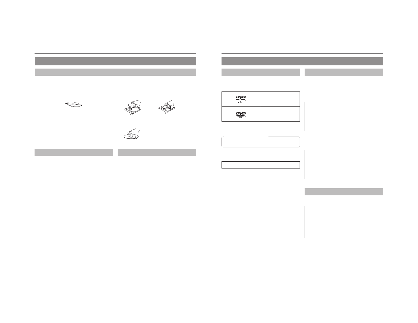
Handling Discs
● Removing a disc ● Placing a disc in its case
● Correct method for holding a disc
Your hands or fingers should not
come into contact with the
recording surface when holding
a disc.
Storing Discs
Avoid storing discs in any of the following locations.
• Areas with high levels of humidity or dust, or areas where
mold is present.
• Areas exposed to direct sunlight or close to heating
equipment.
•Vehicle interiors during summer months.
Take care to avoid dropping or knocking discs.
Place discs in cases and stack these cases for storage.
Discs can be deformed or cracked as a result of stacking,
leaning, or dropping when not inside a case.
Details Regarding Discs
Discs for Recording & Playback
The following shows the discs that can be recorded to and played
using this DVD recorder, in addition to the corresponding display
marks or logos.
DVD-R 12 cm: 4.7 GB
DVD-RW 12 cm: 4.7 GB
* Certain characteristics and properties of a disc can render
them unsuitable for recording or playback.
Recommended manufacturers
DVD-R : JVC, Maxell 2×, 4×, 8×
DVD-RW : JVC 2×, 4×
DVD-R and DVD-RW Details
DVD-R : Only discs that conform with DVD-R Standard 2.0
(video mode) can be used.
DVD-RW : Discs of Version 1.1 or later can be used.
Although Version 1.1 of the DVD-RW Standards
allows the selection of either video mode or VR mode
for recording, this DVD recorder performs recording
in video mode only.
*Version 1.0 of the DVD-RW Standards does not
support video-mode recording, and for this
In terms of recording characteristics, DVD-R and DVD-RW (video
mode) differ as follows.
DVD-R
DVD-RW (video mode)
reason, the corresponding discs cannot be used.
• Each disc can be recorded only one. Accordingly, these
discs are recommended for use in archiving or long-term
storage.
• Once a disc has been finalized, it can also be played on
other DVD players.
• After viewing a disc, all data can be erased and it can be
used to record new content.
• Once a disc has been finalized, it can also be played on
other DVD players.
• It is possible to cancel the finalization and add a recording.
General Version 2.0
(video mode)
Version 1.1 or later
(video mode)
Finalizing
When a DVD-R or a DVD-RW (video mode) has been finalized,
it can be played in the same way as any other DVD using a
standard DVD player. (☞ Page 42)
Recording to unused sections of a disc and the
modification of titles or display styles can be carried
out as required before a disc is finalized.
• In the case of both DVD-Rs and DVD-RWs, it is impossible
to overwrite previously recorded content with new data,
even if the disc in question has not yet been finalized. The
deletion of specific sections of data is also impossible.
• Regardless of whether or not finalization has been carried
out, it will not be possible to use this DVD recorder to
record new content to a DVD-R or DVD-RW that has been
recorded using other devices.
Once a disc has been finalized, it can be used as a
standard DVD and its recorded audio and video can
be played on this and other DVD players.
• After finalizing, a disc’s titles can be selected from the top
menu.
• Additional recording will not be possible after finalizing.
• In the case of a DVD-RW, it is possible to cancel the
finalization and add a recording.
• Although a finalized disc may in principle be played on
other DVD players, certain characteristics of the disc and
its recording conditions may make this impossible.
Playing Discs on this DVD recorder
This DVD recorder is capable of playing any discs that it has
created and finalized.
● The following conditions may occur when attempting to
play discs recorded using other devices on this DVD
recorder.
• Inability to play
• Block-type noise (i.e., mosaic)
• Interruptions in audio and/or video
• Unintentional stopping during playback
● Commercially-available DVD-Videos and DVD-ROMs
cannot be used.
6
7
Page 10
Introduction
Component Names & Functions
Details Regarding Discs (continued)
DVD Data Configuration
Generally speaking, the content recorded on a DVD is separated
into large units referred to as “titles”. A unique number called a
“title number” is assigned to each of these titles, and as a result,
any title can be immediately accessed using its title number. In
addition, each title can be divided into smaller units referred to
as “chapters”. Similarly, a unique number called a “chapter
number” is assigned to each of these chapters, and this allows
any chapter to be immediately accessed using its chapter
number.
Each recording made to a disc is stored as a single title. In this,
each pressing of the STOP button to leave Recording mode
constitutes a different recording. (This action is also referred to
as “title closing”.)
It is also possible to insert chapter marks to partition titles at the
desired points by pressing the REC button while recording. It is
possible to automatically add a chapter mark when recording is
temporarily stopped by pressing the PAUSE button. (Set from
the menu.) In addition, this DVD recorder can also be used to
automatically insert chapter marks at regular intervals.
(CHAPTER CREATION menu settings will be required for this
function.)
Disc
Title 1
Chapter 1 Chapter 2 Chapter 3
● Before a title is closed, it will be possible to modify the style
used for chapter menu display, to change the thumbnails used,
and to input thumbnail names.
● Before a disc is finalized, it will be possible to modify the style
used for the title menu and to input title names.
Title 2
Chapter 1 Chapter 2
Region Codes
One of six numbers referred to as “region codes” is assigned to
DVD content to control the global regions in which this content
may be viewed. If a DVD’s region code does not correspond to
the region code of the DVD player being used, it will not be
possible to play the disc.
● This DVD recorder assigns the region code “ALL” to the discs
that it records.
● It will not be possible to play discs to which region codes have
been assigned.
Screen Sizes
This DVD recorder is capable of recording video content for widescreen TVs (i.e., with a 16:9 aspect ratio).
In addition, signals for normal content with a 4:3 aspect ratio, for
squeezed content (i.e., where the left and right are compressed),
and for letterbox content (i.e., where the top and bottom of the
screen are black) can be recorded as is.
● Thumbnail creation method for use in the title/chapter menu
during wide-signal input can be selected in THUMBNAIL
FORM of the DVD MENU screen. (☞ Page 65)
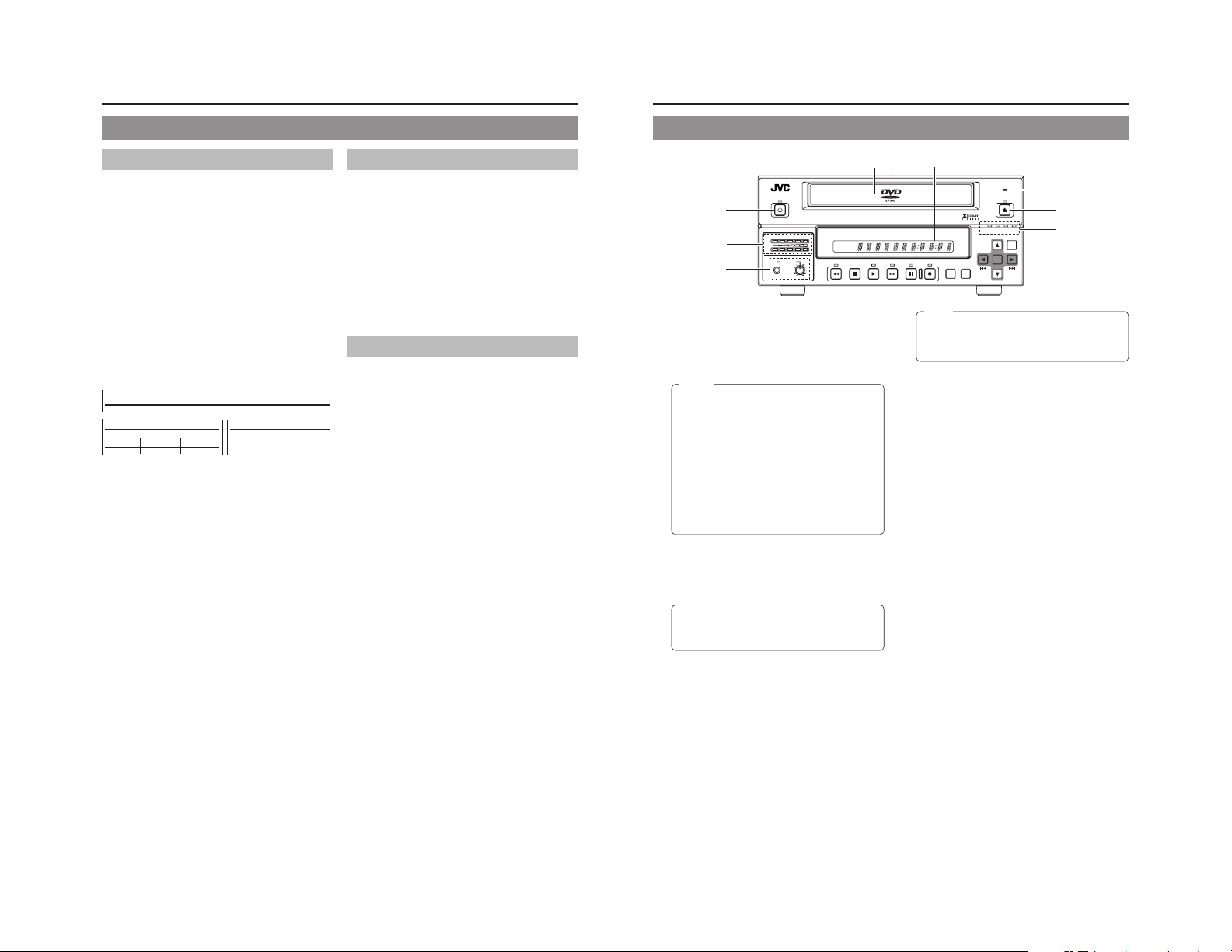
Front Panel
OPERATE
1
AUDIO
5
8
OPERATE button and indicator
1
● This button is used to make it ready for use. Press again to
disable operation (Operate OFF mode).
● The indicator ’s lighting condition depends on the condition
of the DVD recorder and can be one of the following.
Lit in green : Operate ON.
Lit in orange : Operate OFF.
Notes
● The OPERATE button will have no effect if pressed
while the DVD recorder is in either Recording or
Recording Pause mode. This is also the case when
performing finalizing or erasing.
● The DVD recorder continues to use a small amount
of power even after it has been turned off using the
OPERATE button. If it will not be used for an extended
period of time, please set the POWER switch to OFF
to avoid wasting electricity.
● Do not turn the power off when in Operate On mode
as this can result in the DVD recorder being
damaged.
● Malfunction may occur when switching to OPERATE
ON while pressing a key on a connected USB
keyboard.
Disc tray
2
The purpose of the disc tray is to hold DVDs.
This tray opens automatically when the OPEN/CLOSE button
is pressed. In addition, the OPEN/CLOSE button can be
pressed again to close the tray.
Notes
● Do not push the disc tray as it is opening or closing.
● Do not place objects other than discs on the disc
tray.
● Do not press down on the disc tray
BUSY indicator
3
This indicator flashes when the DVD recorder is in Recording
Pause mode or when it is performing time-consuming
operations such as title closing, finalizing, and erasing. None
of the DVD recorder’s buttons will have any effect if pressed
while the BUSY indicator is flashing.
OPEN/CLOSE button and indicator
4
This button is used to open and close the disc tray.
In addition, the OPEN/CLOSE indicator is lit up while the disc
tray is opening, and also when it is open.
CH1
CH2
PHONES REV
DOLBY DIGITAL
LPCMMPEG
DVD RECORDER
BD-X201M
TITLE
CHAPTER
STOP PLAY FWD PAUSE REC
Audio level indicator
5
These meters are used to indicate the current level of audio
on Channel 1 and Channel 2.
Specifically, the audio level meters indicate the audio recording
levels when the DVD recorder is in Recording mode, and the
audio playback levels when it is in Playback mode.
(Adjustment of the audio recording levels: ☞ Page 32.)
LCD display
6
The LCD display is used to present important information.
During recording or playback, for example, the title, chapter
number, and elapsed time are indicated on the LCD display.
(☞ Page 14 for more details.)
Video input indicators
7
OPTION indicator
This indicator is lit up or flashes when INPUT SELECT
from the INPUT SELECT MENU screen has been set to
OPTION. (This setting cannot be carried out using the DVD
recorder alone.)
DV indicator
This indicator is lit up or flashes when INPUT SELECT
from the INPUT SELECT MENU screen has been set to
DV. Specifically, the indicator is lit up when an input signal
is present, and it flashes when no signal is present.
Y/C indicator
This indicator is lit up or flashes when INPUT SELECT
from the INPUT SELECT MENU screen has been set to
Y/C. Specifically, the indicator is lit up when an input signal
is present, and it flashes when no signal is present.
LINE indicator
This indicator is lit up or flashes when INPUT SELECT
from the INPUT SELECT MENU screen has been set to
LINE. Specifically, the indicator is lit up when an input signal
is present, and it flashes when no signal is present.
Phones jack and volume adjuster
8
The phones jack allows headphones to be connected to the
DVD recorder for monitoring of audio levels; in addition, the
headphone volume can be adjusted using the volume adjuster.
Note that this adjuster has no effect on the actual recording
levels.
62
BUSY
OPEN/CLOSE
3
4
OPTION DV Y/C LINE
SET UP
TOP
MENU MENU
Note
The OPEN/CLOSE button will have no effect if pressed
while the DVD recorder is in either Recording or
Recording Pause mode. This is also the case when
performing finalizing or erasing.
SET
7
8
9
Page 11
Component Names & Functions
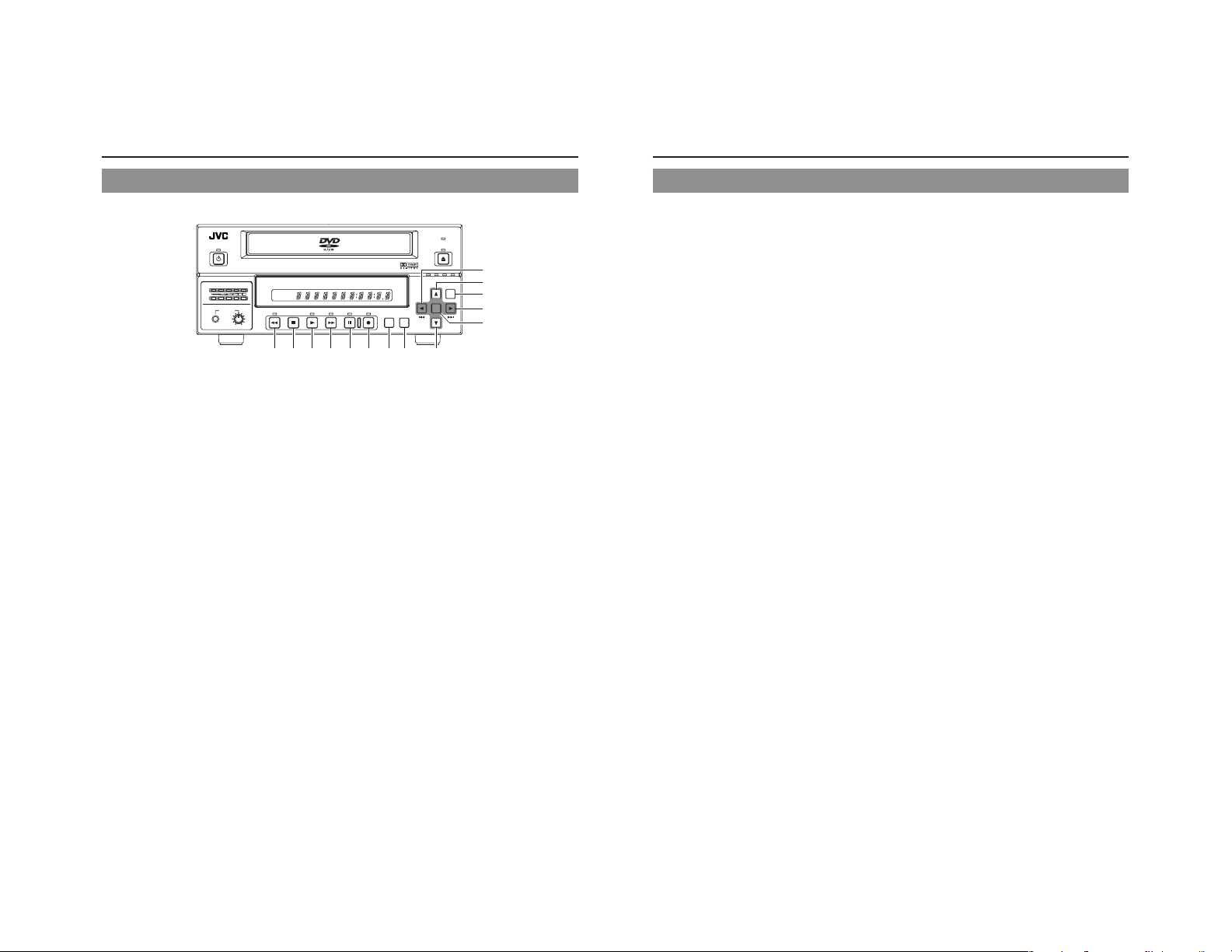
Front Panel (continued)
OPERATE
DVD RECORDER
AUDIO
CH1
CH2
PHONES REV
DOLBY DIGITAL
LPCMMPEG
STOP PLAY FWD PAUSE REC
90!@#$%^
REV button and indicator
9
● Press this button during playback or fast-forward mode to
start fast-reverse play. If pressed during fast-reverse play,
this button toggles the speed of fast-reverse play between
low speed and high speed.
● Press this button in still mode or during slow-forward play
to start slow-reverse play. If pressed during slow-reverse
play, this button toggles the speed of slow-reverse play
between low speed and high speed.
● The REV indicator is lit up during fast-reverse and slowreverse play.
STOP button
0
● This button has the following effect when pressed in
Recording or Recording Pause mode.
If EDIT MENU from the DVD MENU screen is set to
DISABLE, the DVD recorder stops recording (i.e., it
performs title closing).
If EDIT MENU from the DVD MENU screen is set to
ENABLE, the DVD recorder stops recording and the
THUMBNAIL EDIT screen is displayed. It will then be
possible to modify the chapter menu.
● When the STOP button is pressed in Playback mode, the
DVD recorder stops playback.
PLAY button and indicator
!
● If this button is pressed together with the REC button while
a recordable disc is inserted into the DVD recorder,
recording will be started.
● When the PLAY button is pressed in Recording Pause
mode, the DVD recorder restarts recording.
● When an unfinalized disc is inserted and this button is
pressed, playback of the most recent title starts.
● The PLAY indicator is lit up in Recording and Playback
modes.
FWD button and indicator
@
● Press this button during playback or fast-reverse mode to
start fast-forward play. If pressed during fast-forward play,
this button toggles the speed of fast-forward play between
low speed and high speed.
● Press this button in still mode or during slow-reverse play
to start slow-forward play. If pressed during slow-forward
play, this button toggles the speed of slow-forward play
between low speed and high speed.
● The FWD indicator is lit up during fast-forward and slowforward play.
BD-X201M
TITLE
CHAPTER
BUSY
OPEN/CLOSE
SET UP
)
*
&
⁄
TOP
MENU MENU
OPTION DV Y/C LINE
SET
¤
(
PAUSE button and indicator
#
● When this button is pressed while recording, the recorder
enters the recording pause mode.
● If this button is pressed during playback, the DVD recorder
switches to Still mode and freezes playback. If the PAUSE
button is then pressed again in Still mode, the DVD recorder
will advance playback by a single field.
● The PAUSE indicator is lit up in Recording Pause and Still
modes.
REC button and indicator
$
● If this button is pressed together with the PLAY button in
Stop mode, recording will be started.
• If the current disc is blank or title closing has been carried
out, a new title will be created and recording will start at
Chapter 1.
● When this button is pressed during recording, a new chapter
and index will be setup within the continuous video data.
● Press this button during playback to write index.
● If this button is pressed and held for more than 2 seconds
while the DVD recorder is stopped or inserted with no disc,
input signal encoded/decoded in MPEG will be output via
the VIDEO OUT terminal on the rear panel. This will continue
for as long as the button is held, and it allows the DVD
recording quality to be confirmed. Audio will be muted at
this time.
● The REC indicator is lit up in Recording and Recording
Pause modes.
TOP MENU button
%
If this button is pressed while the DVD recorder is in a playback
condition, the current DVD’s top menu (or title menu) will be
displayed on the monitor screen.
If the DVD does not contain a title menu, nothing will be
displayed when the TOP MENU button is pressed.
MENU button
^
If this button is pressed while the DVD recorder is in a playback
condition, the chapter menu for the currently selected title
will be displayed on the monitor screen.
If the DVD title does not contain a chapter menu, nothing will
be displayed when the MENU button is pressed.
SET UP button
&
● This button can be pressed to display the Setup Menu on
the monitor. A wide range of different menu settings can
then be made via the Setup Menu. (☞ Page 58)
In addition, the SET UP button can be pressed again to
hide the Setup Menu.
● If the SET UP button is pressed in Recording or Recording
Pause mode, setting data relevant to recording (i.e., video
bit rate and audio encoding format) will be displayed onscreen. In addition, the SET UP button can be pressed again
to hide this information.
● Press this button when in the Playback mode to display the
INDEX MANAGER screen.
When the INDEX MANAGER screen is displayed, press
this button to return to the original screen. (☞ Page 56)
[6] button
*
● This button is used to select menu items or setting values
when the Setup Menu is displayed.
● Press this button during playback to playback the next title.
● If a title menu or chapter menu is displayed, this button
can be used to select a menu number for playback.
Specifically, pressing of this button moves the selection
position upward.
● The 6 button can be used to adjust the audio recording
levels when the DVD recorder is stopped or in Recording
Pause mode.
• If AUDIO REC VOLUME MODE from the RECORDER
MENU (2/2) screen is set to BOTH and this button is
pressed while either the 8 or t button is being held, the
audio recording levels for both Channel 1 and Channel 2
will increase.
• If AUDIO REC VOLUME MODE from the RECORDER
MENU (2/2) screen is set to INDEPENDENCE and this
button is pressed while the 8 button is being held, the
audio recording level for Channel 1 will increase. Similarly,
if the 6 button is pressed while the t button is being
held, the audio recording level for Channel 2 will increase.
[7] button
(
● This button is used to select menu items or setting values
when the Setup Menu is displayed.
● Press this button during playback to playback the previous
title.
● If a title menu or chapter menu is displayed, this button
can be used to select a menu number for playback.
Specifically, pressing of this button moves the selection
position downward.
● The 7 button can be used to adjust the audio recording
levels when the DVD recorder is stopped or in Recording
Pause mode.
• If AUDIO REC VOLUME MODE from the RECORDER
MENU (2/2) screen is set to BOTH and this button is
pressed while either the 8 or t button is being held, the
audio recording levels for both Channel 1 and Channel 2
will decrease.
• If AUDIO REC VOLUME MODE from the RECORDER
MENU (2/2) screen is set to INDEPENDENCE and this
button is pressed while the 8 button is being held, the
audio recording level for Channel 1 will decrease. Similarly,
if the 7 button is pressed while the t button is being
held, the audio recording level for Channel 2 will decrease.
[8] button
)
● If a title menu or chapter menu is displayed, this button
can be used to select a menu number for playback.
Specifically, pressing of this button moves the selection
position to the left.
● This button can be pressed while the DVD recorder is
playing to move playback to the start of the current chapter.
● The 8 button can be used to adjust the audio recording
levels when the DVD recorder is stopped or in Recording
Pause mode.
• If AUDIO REC VOLUME MODE from the RECORDER
MENU (2/2) screen is set to INDEPENDENCE and either
the 6 or 7 button is pressed while this button is being
held, the audio recording level for Channel 1 will be
adjusted accordingly.
• If AUDIO REC VOLUME MODE from the RECORDER
MENU (2/2) screen is set to BOTH and either the 6 or 7
button is pressed while this button is being held, the audio
recording levels for both Channel 1 and Channel 2 will be
adjusted accordingly.
• If this button is pressed together with the t button, the
audio recording levels will be returned to their default
settings (i.e., unity gain).
[t] button
⁄
● If a title menu or chapter menu is displayed, this button can
be used to select a menu number for playback. Specifically,
pressing of this button moves the selection position to the
right.
● This button can be pressed while the DVD recorder is
playing to move playback to the start of the next chapter.
● The t button can be used to adjust the audio recording
levels when the DVD recorder is stopped or in Recording
Pause mode.
• If AUDIO REC VOLUME MODE from the RECORDER
MENU (2/2) screen is set to INDEPENDENCE and either
the 6 or 7 button is pressed while this button is being
held, the audio recording level for Channel 2 will be
adjusted accordingly.
• If AUDIO REC VOLUME MODE from the RECORDER
MENU (2/2) screen is set to BOTH and either the 6 or 7
button is pressed while this button is being held, the audio
recording levels for both Channel 1 and Channel 2 will be
adjusted accordingly.
• If this button is pressed together with the 8 button, the
audio recording levels will be returned to their default
settings (i.e., unity gain).
SET button
¤
● This button is used to confirm the selection of menu items
or setting values when the Setup Menu is displayed.
● When this button is pressed during normal screen display,
the counter from the DVD recorder’s LCD display will switch
to display of either the elapsed recording/playback time or
the remaining disc/title time.
10
11
Page 12
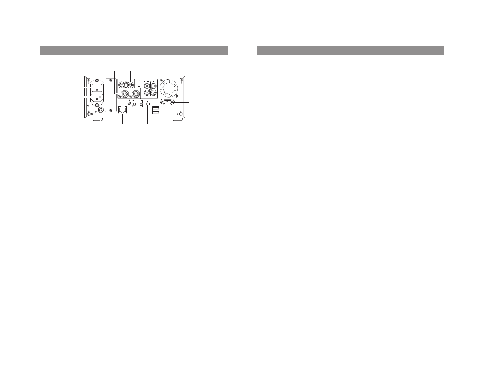
Component Names & Functions
Rear Panel
12345
MAIN
POWER
^
%
AC IN
$
VIDEO LINE IN terminal (BNC)
1
This terminal allows composite video signals to be input to
the DVD recorder.
In order to select these signals for input, set INPUT SELECT
from the INPUT SELECT MENU screen to LINE.
● SETUP from the SYSTEM MENU (1/2) screen should be
set in accordance with whether or not this input signal is a
setup signal. (NTSC only)
VIDEO Y/C IN terminal (4-pin)
2
This terminal allows YC separate video signals to be input to
the DVD recorder.
In order to select these signals for input, set INPUT SELECT
from the INPUT SELECT MENU screen to Y/C.
● SETUP from the SYSTEM MENU (1/2) screen should be
set in accordance with whether or not this input signal is a
setup signal. (NTSC only)
● This terminal’s specification (i.e., S1 or S2) can be selected
using Y/C TERMINAL MODE from the SYSTEM MENU (2/
2) screen.
VIDEO LINE OUT terminal (BNC)
3
This terminal is used to connect the DVD recorder to a monitor.
● When the DVD recorder is in Stop or Recording mode, the
video input signal is output on the E-E screen as a
composite video signal.
● If the REC button is pressed and held for at least 2 seconds
while the DVD recorder is stopped, the input signal will be
subjected to MPEG encode/decode processing and output
via the VIDEO LINE OUT terminal. This will continue for as
long as the REC button is held, and it allows the DVD
recording quality to be confirmed.
● Playback from the DVD is output as a composite signal
when in Playback mode.
● The Setup Menu, title menu, chapter menus, and other
setting and control screens are displayed on the monitor
connected to this terminal.
● Status and alarm information is also displayed on-screen.
(The DISPLAY MENU screen can be used to indicate which
items are to be displayed.)
VIDEO
LINE
Y/C
OUT
IN
FOOT SW
1
FOR SERVICE
#@ ! 09
67
AUDIO
CH1
INPUT
LEVEL
IN
OUT
+
4dB
-
8dB
Y/C
CH2
DV IN/OUT
2
VIDEO Y/C OUT terminal (4-pin)
4
For output of YC separate video signals.
● Information that is the same as that of the VIDEO LINE
OUT terminal is being output.
● This terminal’s specification (i.e., S1 or S2) can be selected
using Y/C TERMINAL MODE from the SYSTEM MENU (2/
2) screen.
AUDIO INPUT LEVEL switch
5
This switch is used to set the standard level for audio input.
+4dB : The standard level is set to +4 dB.
–8dB : The standard level is set to –8 dB.
AUDIO IN terminals (RCA × 2)
6
These terminals allow analog audio signals to be input to the
DVD recorder.
● In order to select these signals for input, set INPUT SELECT
from the INPUT SELECT MENU screen to LINE or Y/C.
AUDIO OUT terminals (RCA × 2)
7
These terminals allow analog audio signals to be output from
the DVD recorder.
● When the DVD recorder is in Stop or Recording mode, the
audio input signals (i.e., E-E signals) are output via these
terminals.
● Audio from the DVD is output when in Playback mode.
RS-232C REMOTE terminal (D-sub 9-pin female)
8
Operation of this unit can be controlled externally by
connecting to an RS-232C control device.
USB terminals (2)
9
For connecting to a USB-supported keyboard.
A keyboard can be used as an alternative to the DVD
recorder’s buttons when using setting and control screens.
The input of text in setting screens is carried out using a
keyboard.
● It is not be possible to operate devices other than a keyboard
by connecting them to the USB terminal.
● Set KEYBOARD STYLE from the SYSTEM MENU (1/2)
screen in accordance with the keyboard’s input language.
Recommended manufacturers: Logitech
REMOTE
USB
8
DV IN/OUT terminal
0
This I/O terminal for digital signals conforms with IEEE1394
specifications.
● In order to select this terminal’s audio and video signals for
input, set INPUT SELECT from the INPUT SELECT MENU
screen to DV.
● REMOTE SELECT from the REMOTE MENU screen is
used to select a control method for this terminal as follows.
DV(SLAVE) : The DVD recorder operates as a slave
DV(TRIGGER) : The DVD recorder performs recording
FOOT SW 1/2 terminal
!
FOOT SW 1 : For controlling the Record/Record Pause
FOOT SW2 : For adding chapters or indexes according to
For selecting the method of control by this terminal using the FOOT
SW1/2 items on the REMOTE menu screen. (☞ Page 69)
FOR SERVICE terminal (RJ-45)
@
● Connect this terminal to a PC that has been installed with
utilities for this unit, such as application software for creating
title/chapter menus.
● NETWORK settings must be carried out using the
NETWORK MENU screen
Optional-board slot cover
#
This cover is removed to allow commercially-available optional
boards to be installed.
Equipotential Terminal
$
Ensure proper connection of the equipotential terminal for
each device when connecting this unit to other devices.
AC IN terminal (3P)
%
For connecting to the power outlet using the power cord
supplied.
MAIN POWER switch
^
Switch for turning ON/OFF the power.
● When the power is turned ON, operating mode can be
selected using the AC IN MODE item on the SYSTEM
MENU (2/2) screen. (☞ Page 64)
device and is controlled by commands
from a master device.
in response to operation of the trigger
button on a camera capable of DV
triggering (i.e., a GY-DV5000 from JVC).
functions of this unit by connecting to an
external switch (foot switch, etc.).
switch signals by connecting to an external
switch (foot switch, etc.).
12
13
Page 13
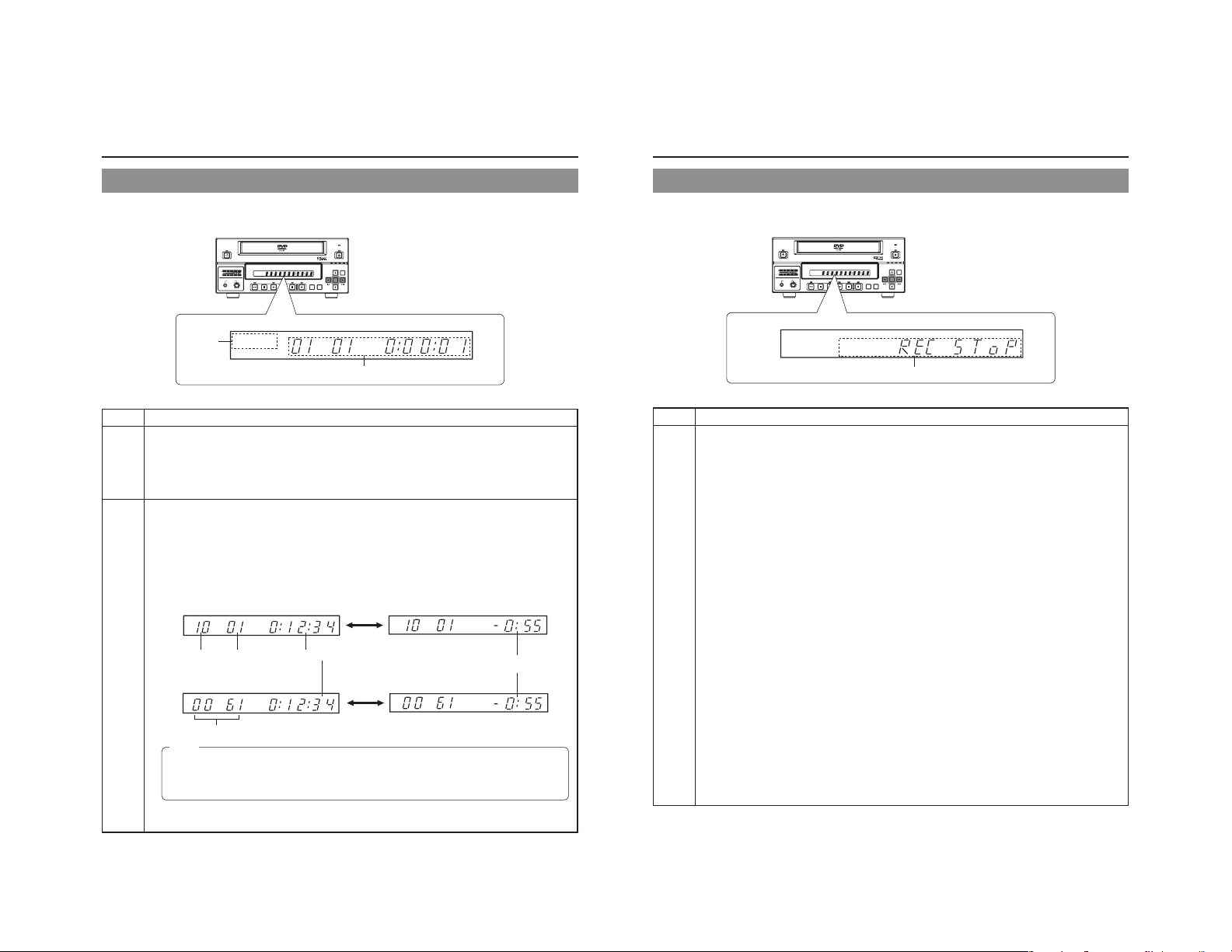
LCD Display and On-Screen Content
LCD Display
The following information and data is presented on the DVD recorder’s LCD display.
BUSY
1
OPERATE
CH1
CH2
AUDIO
PHONES REV
DOLBY DIGITAL
LPCMMPEG
DOLBYDIGITAL
LPCM MPEG
TITLE
CHAPTER
STOP PLAY FWD PAUSE REC
TITLE
TOP
MENU MENU
OPTION DV Y/C LINE
OPEN/CLOSE
SET
SET UP
CHAP
2
No. Description
Encoding format for audio recordings (LPCM / DOLBY DIGITAL / MPEG) …… MPEG can only be selected
1
when in the PAL mode
Recording mode : The encoding format set using AUDIO ENCODE from the RECORDER MENU (1/2) screen is
Playback mode : The encoding format used for audio on the current disc is displayed. This will not be displayed
Information relevant to the current mode.
2
Title number / Chapter number / Index number / Counter
Display details can be selected using the LCD item on the DISPLAY menu screen.
● Displays the title no., chapter no. and elapsed time of a title when the LCD item is set to TITLE+CHAPTER.
● Displays the index no. and elapsed time of a title when the LCD item is set to INDEX.
Press the SET button to alternate counter display between elapsed time and remaining time.
Remaining Time: Displays the remaining time of the disc (hr: min) during recording and remaining time of the title
during playback.
When the LCD item is set to TITLE+CHAPTER
When the LCD item is set to INDEX
Memo
● The remaining disc and title time depend on the amount of data comprising video, and for this reason, they
●
displayed. This will not be displayed when the AUDIO ENCODE item is set to NO AUDIO.
during playback of a recorded disc with the AUDIO ENCODE item set to NO AUDIO.
SET Button
Title No. Chapter No.
Title Recording Elapsed Time (hr: min: sec)
Disc Remaining Time
(hr: min)
SET Button
Index No. (4 digits)
should be taken as being a general indication and not an exact figure.
When the PLAYBACK & 232C TYPE item on the SYSTEM MENU [1/2] screen is set to VTR, the elapsed time
and index no. will represent the total time and total number respectively as accumulated from Title 1. (☞ Page 63)
BUSY
TOP
MENU MENU
OPTION DV Y/C LINE
CHAP
OPEN/CLOSE
SET
SET UP
OPERATE
AUDIO
CH1
CH2
PHONES REV
DOLBYDIGITAL
LPCM MPEG
TITLE
DOLBY DIGITAL
LPCMMPEG
STOP PLAY FWD PAUSE REC
CHAPTER
TITLE
2
No. Description
Indication of the current operating mode
2
PLEASE WAIT : The DVD recorder is starting up.
OPERATE OFF : The DVD recorder is preparing to shut down.
NO DISC : The DVD recorder currently contains no disc.
LOADING : A disc is being loaded into the DVD recorder.
DVD-R : The current disc is a non-finalized DVD-R. (Approximately 3 seconds)
DVD-RW : The current disc is a non-finalized DVD-RW. (Approximately 3 seconds)
DVD : The current disc is a finalized DVD-R or DVD-RW. (Approximately 3 seconds)
REC PAUSE : The DVD recorder is switching from Recording mode to Recording Pause mode.
REC STOP : The DVD recorder is switching from Recording mode to Stop mode.
MENU EDIT : A title menu or chapter menu is currently being edited.
EJECT : The current disc is being ejected.
TITLE CLOSE : The DVD recorder is performing title-close processing.
FINALIZE : The DVD recorder is finalizing the disc.
QUICK ERASE : The DVD recorder is erasing data from a DVD-RW disc.
FULL ERASE : The DVD recorder is erasing data from a DVD-RW disc.
INDEX WRITE : Displayed when index is written. (Approximately 3 seconds)
INDEX ERASE : Displayed when index is erased. (Approximately 3 seconds)
TOP MENU : The disc’s top menu is being played.
MENU : A menu is being played.
ENCODE XX : Encoded video is being output. (XX : Encode quality (UXP, XP, SP, EP, DLP, DEP))
RESTORE XX : Displayed when executing disc recovery. XX: Progress (%)
Display of the Setup Menu
Menu items and setting values from the Setup Menu are displayed. (☞ Page 58)
Event messages
Messages relating to incorrect operation and the like are displayed for approximately 3 seconds. (☞ Page 18)
Alarm messages
Alarms are displayed when the DVD recorder cannot obey a command. (☞ Page 19)
14
15
Page 14
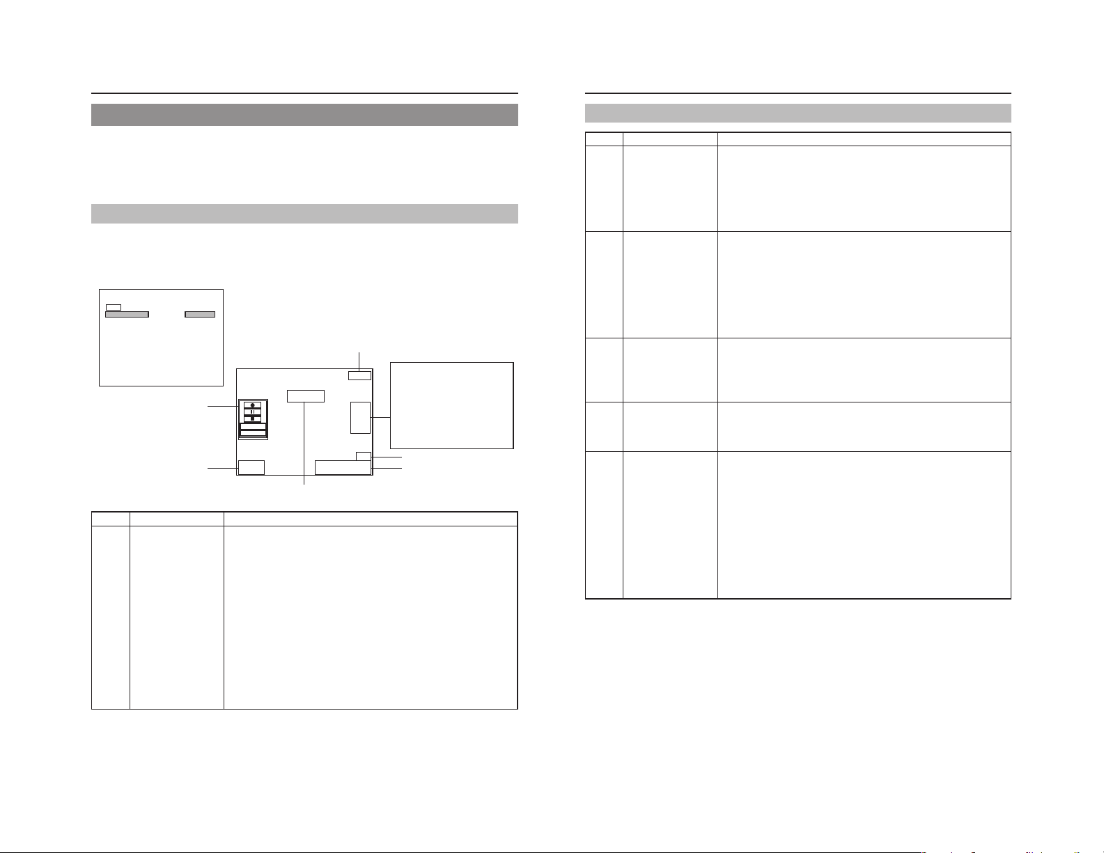
LCD Display and On-Screen Content
On-Screen Content
In addition to E-E and playback screens, the monitor connected to the DVD recorder’s VIDEO LINE OUT terminal can display the
following.
● Status messages
● Event messages
● Alarm messages
● The Setup Menu (☞ Page 58)
● Recording-operation control screens: REC CONTROL panel (☞ Page 40)
Status Messages
The DVD recorder’s setting condition and operation status are indicated by status messages, and these messages are displayed
on E-E or playback screens.
The DISPLAY MENU screen can be used to indicate whether or not status messages are to be displayed.
DISPLAY MENU screen
DISPLAY MENU
MENU
DISPLAY
TITLE/CHAPTER/INDEX
RECORDER MODE
TIME/DATE
REMAIN
DATE STYLE
LCD
ON
TITLE+CHAPTER
ON
TIME+DATE
ON
MM/DD/YY
TITLE+CHAPTER
5
No. Item Description
Operation Mode This area indicates the DVD recorder’s current mode of operation.
1
16
To display status messages:
Set DISPLAY from the DISPLAY MENU screen to ON.
The various items of status information for display can be selected.
If DISPLAY is set to OFF, no status information will be displayed.
TITLE 01 0:11:22
CHAPTER
01 0:11:22
4
000 min
REC
Data relevant to recording:
If the SET UP button is pressed
while in Recording mode, the
video encode quality and the
audio encoding format will be
displayed. If the SET UP button is
then pressed once again, this
information is removed from the
screen.
1
23
FINALIZE
DISC
TITLE
04/05/04
11:20:00
Status Messages
DVD-RW
6
Use RECORDER MODE from the DISPLAY MENU screen to indicate whether or not
this is to be displayed.
NO DISC : The DVD recorder currently contains no disc.
EJECT : The current disc is being ejected.
STOP : Stop mode
REC : Recording mode
REC PAUSE : Recording Pause mode
PLAY:Playback mode
STL : Still mode
FWD >> : Fast-forward playback (low speed)
FWD >>> : Fast-forward playback (high speed)
REV << : Fast-reverse playback (low speed)
REV <<< : Fast-reverse playback (high speed)
SLOW FWD >>> : Slow-forward playback (high speed)
SLOW FWD >> : Slow-forward playback (low speed)
SLOW REV <<< : Slow-reverse playback (high speed)
SLOW REV << : Slow-reverse playback (low speed)
LOADING : A disc is being loaded.
RESTORE : Disc recovery in progress. (☞ Page 41)
No. Item Description
Title number / Chapter
2
number / Index number /
Counter
Date / Time
3
Remaining time
4
REC CONTROL panel
5
DISC STATUS /
6
Index display
Use TITLE/CHAPTER / INDEX from the DISPLAY MENU screen to indicate whether or
not this is to be displayed.
OFF : No information is displayed
TITLE+CHAPTER
INDEX+TITLE : Index no. and elapsed time of a title (hr: min: sec) are displayed.
* When the PLAYBACK & 232C TYPE item on the SYSTEM MENU (1/2) screen is set
to VTR, the elapsed time and index no. will represent the total time and total number
respectively as accumulated from Title 1. (☞ Page 63)
Use TIME/DATE from the DISPLAY MENU screen to select the way in which the date
and time are displayed.
OFF : No information is displayed.
DATE : Only the date is displayed.
TIME : Only the time is displayed.
TIME+DATE : Both date and time are displayed.
● The date display style can be changed using DATE STYLE from the DISPLAY MENU
screen.
Recording mode : The date and time from the internal clock are displayed.
Playback mode : The date and time of disc recording are displayed.
Use REMAIN from the DISPLAY MENU screen to indicate whether or not this is to be
displayed.
Recording mode : The amount of video that can still be recorded on the current disc is
Playback mode : Not displayed
* Remaining time is to be used as a general guide, not as an exact figure.
Provided that a recordable disc has been inserted, this panel will be displayed whenever
REC CONTROL from the REMOTE menu screen is set to ON.
The REC CONTROL panel can be used to control recording operations. (☞ Page 43)
● This is displayed even when the DISPLAY item is set to OFF.
When a disc is inserted into the DVD recorder, one of the following disc status is displayed
on the monitor screen (Approximately 3 seconds)
DVD-R :The current disc is a non-finalized DVD-R.
DVD-RW : The current disc is a non-finalized DVD-RW.
DVD : The current disc is a finalized DVD-R or DVD-RW.
INVALID DISC : The current disc is neither DVD-R or DVD-RW.
● The following will be displayed when index is recorded or erased. (3 seconds)
INDEX WRITE : Displayed when writing index. (This is not displayed if TITLE/
INDEX ERASE : Displayed when erasing index.
This is not displayed if DISPLAY item from the DISPLAY MENU screen is set to OFF.
:Title no., chapter no. and elapsed time of a title (hr: min: sec) are
displayed.
displayed (in minutes).
(Displayed while being inserted.)
CHAPTER/INDEX item from the DISPLAY MENU screen is set to
INDEX+TITLE or LCD item is set to INDEX.)
17
Page 15

LCD Display and On-Screen Content
Event Messages
Event messages are displayed on the DVD recorder’s LCD display and on the monitor when incorrect operations are attempted.
These messages will remain on-screen for approximately 3 seconds.
Monitor screen
TITLE FULL
04/05/04
11:20:00
Monitor message
LCD display
message
INVALID TV INVALId TV A signal of an invalid format has been input.
TITLE FULL TITLE FULL Recording was attempted on a disc already containing 99 titles.
INDEX FULL INdEX FULL An attempt was made to add a index to a title already containing 99 index.
CHAPTER FULL CHAP FULL An attempt was made to add a chapter to a title already containing 99 chapter.
NOT FINALIZE NoT FINAL An attempt was made to eject a disc before it was finalized.
———— A L-xxxx-R Set value is displayed when changing the recording level of analog audio.
———— d L-xxxx-R Set value is displayed when changing the recording level of digital audio.
OPE LOCK oPE LoCK This is displayed when buttons on this unit are operated while the Operation Lock is
TITLE 01 0:11:22
CHAPTER
01 0:11:22
000 min
REC
Event messages:
Displayed when
DISPLAY from
the DISPLAY
MENU screen is
set to ON.
DOLBYDIGITAL
LPCM MPEG
LCD display
Event message
Description
Alternatively, an attempt has been made to play a disc containing signals of an invalid
format.
activated. Operation Lock can be canceled by setting the OPERATION LOCK item
on the SYSTEM MENU (2/2) screen to OFF.
Alarm Messages
Alarm messages are displayed on the DVD recorder’s LCD display and on the monitor when the recorder cannot obey a command.
These messages will remain on-screen until the next operation is carried out.
Monitor screen
REC INHIBIT
04/05/04
11:20:00
Monitor message
LCD display
message
INVALID DISC INVALId dISC The current disc is not a DVD-R or DVD-RW.
NOT SUPPORT NoT SUPPoRT A disc recorded using a different DVD recorder was inserted or played.
DISC
REC INHIBIT REC INH ● Recording was attempted using a disc on which no more data can be recorded.
COPY INHIBIT CoPY INH Recording of a copy-protected signal was attempted.
DISC FULL dISC FULL All remaining space on the disc is used up during recording.
CELL OVER CELL oVER The number of cells for a single title exceeded 255.
OVERHEATING! oVERHEATING Displayed when the internal temperature of the set rises due to fan malfunction, etc.
INVALID SYNC INVALId SYNC This is displayed if recording is discontinued when signals are interrupted and out of
———— ERRoR This is displayed when playback or recording is stopped due to dirt or damage on the
FAN S TOP FAN SToP This is displayed when the fan stops.
TITLE 01 0:11:22
CHAPTER
01 0:11:22
000 min
REC
Alarm messages:
Displayed when
DISPLAY from the
DISPLAY MENU
screen is set to
ON.
DOLBYDIGITAL
LPCM MPEG
LCD display
Alarm message
Description
● The current disc is a non-finalized disc to which no more data can be recorded.
This will be displayed when the recording time for a single title is exceeded as a
result of setting ENCODE QUALITY to a low quality, recording content with little
movement, or other similar factors.
In this case, immediately turn off the power and discontinue use. The power will
automatically shut down in about 20 minutes after the OVERHEATING display.
sync during recording.
disc. In this case, either clean the disc or replace it.
18
CAUTION
If alarm messages such as “INVALID DISC” are displayed several times when a disc recorded using this DVD recorder or a
blank disk is inserted, there is a possibility that the disc itself has been damaged. In such a case, the damaged disc should be
replaced with a new one.
If the alarm messages continue to appear after replacing the disc, the problem may lie within the DVD recorder, and in such a
case, you are recommended to contact either the store where this DVD recorder was purchased or your JVC authorized
dealer.
19
Page 16

Preparation
Signal Connections
Audio and video signals
Video output
Note 1
Input
YC separate
Note 4
MAIN
POWER
AC IN
Composite
LINE IN
IN
FOR SERVICE
AUDIO IN
LINE OUT
VIDEO
LINE
Y/C
OUT
Note 5
Note 3
Note 4
Y/C OUT
INPUT
LEVEL
+
4dB
-
8dB
Y/C
FOOT SW
1
2
AUDIO
DV IN/OUT
CH1
IN
CH2
Composite
YC separate
Analog audio
AUDIO OUT
OUT
USB
USB
REMOTE
REMOTE
PHONES
(on front panel)
Keyboard
Monitor TV
Headphones
Stereo
DV
RS-232C
REMOTE
Audio output
Input
Analog audio
Note 2
DV
DV IN/OUT Y/C IN
Note 6
DV IN/OUT
REMOTE cable
Note 1: The video signal for input is selected using INPUT SELECT from the INPUT SELECT MENU screen.
Note 2: The audio signals for input are selected using INPUT SELECT from the INPUT SELECT MENU screen.
When either LINE or Y/C is set for INPUT SELECT, the analog audio signals from the AUDIO IN terminals will be selected
for input.
When DV is set for INPUT SELECT, the DV audio signals from the DV IN/OUT terminal will be selected for input.
Note 3: When the DVD recorder is in Stop or Recording mode, the video input signal is output on the E-E screen as a composite
video signal.
In addition, the Setup Menu and other setting screens are also displayed on the monitor connected to this terminal. The
DVD recorder’s operation status and other relevant information are displayed on-screen when DISPLAY from the DISPLAY
MENU screen has been set to ON.
Note 4: The Y/C IN/OUT terminal’s specification (i.e., S1 or S2) can be selected using Y/C TERMINAL MODE from the SYSTEM
MENU (2/2) screen. The same information as with the VIDEO LINE OUT terminal is output from the Y/C OUT terminal.
Note 5: The standard input level for audio signals input via the AUDIO IN terminals (i.e., +4 dB or –8 dB) can be selected using the
AUDIO INPUT LEVEL switch on the rear panel.
Note 6: Use the following cable as the DV cable.
VC-VDV204 (2m, 4P-4P) from JVC
VC-VDV206 (2m, 4P-6P) from JVC
Power Connections
Connect the Power cord (included) to the DVD recorder.
MAIN
POWER
MAIN POWER switch
Power cord
(included)
AC
OPERATE indicator
OPERATE button
CH1
CH2
Turning the Power On
While in Operate Off mode (i.e., the OPERATE indicator
is lit up in orange), press the OPERATE button.
● The power will turn on, the color of the OPERATE indicator
will change to green, and the DVD recorder will become
ready for use. (Operate On mode)
Note
● A period of 45 seconds may pass before the DVD recorder
adopts Operate On mode as it prepares for operation.
● A small amount of current will be required by the DVD
recorder when in Operate Off mode.
AC IN
OPERATE
AUDIO
PHONES REV
1.
Connect the Power cord (included) to the DVD
recorder’s AC IN terminal.
2.
Connect the power cord (included) into an
electrical outlet.
3.
Set the MAIN POWER switch to ON.
● Power will be supplied to the DVD recorder and the
OPERATE indicator will be lit up in green. (Operate On
mode)
● The AC IN MODE item on the SYSTEM MENU (2/2)
screen can be used to specify whether to start up in the
Operate ON or OFF mode when the power switch is turned
ON.
(☞ Page 64)
CAUTION
● Always use the AC cord provided with the DVD recorder.
The use of other power cord should be avoided.
● Do not turn the power off during recording or playback.
In the case of DVD-R discs, failure to observe this
precaution will result in the discs becoming unusable.
In the case of DVD-RW discs, it will be necessary to erase
all data from the disc and to start recording again from
the beginning.
Turning the Power Off
Stop the DVD recorder.
(It is recommended that you eject the disc at this time.)
1.
Press the OPERATE button.
● The DVD recorder will adopt Operate Off mode and the
color of the OPERATE indicator will change to orange.
2.
If the DVD recorder will not be used for an extended
period of time, set the MAIN POWER switch to OFF.
● When disconnecting the power cord, remove the power
cord from the electrical outlet first.
Notes
● Pressing the OPERATE button will have no effect in
Recording mode or Recording Pause mode.
● Pressing this button also has no effect during finalizing
and erasing.
20
21
Page 17

Preparation
Inserting & Removing Discs
Disc tray
OPERATE
AUDIO
CH1
CH2
PHONES REV
Inserting a Disc
Press the OPERATE button to activate Operate On mode.
1.
Press the OPEN/CLOSE button.
● The disc tray will open automatically.
While the disc tray is open, the OPEN/CLOSE indicator
will be lit up.
2.
Place the disc on the disc tray.
Ensure that the disc is inserted correctly into the tray’s recess
with the printed side facing upward.
● Carefully place the disc in the tray so as not to hit the front
panel.
3.
Press the OPEN/CLOSE button.
● The disc tray will close automatically.
Notes
● When a disc is inserted, information about that disc is
displayed on-screen. (☞ Page 17)
● When either a new DVD-RW or one that has been erased
on another machine is inserted, quick erase starts up.
(☞ Page 28)
●
When the AUTO CANCEL DISC FINALIZE item on the
DISC menu screen is set to ON, finalization will be
automatically canceled when a DVD-RW that is finalized
using this unit has been inserted. (☞ Page 61)
TITLE
DOLBY DIGITAL
LPCMMPEG
STOP PLAY FWD PAUSE REC
BUSY
OPEN/CLOSE
OPEN/CLOSE indicator
OPEN/CLOSE button
OPTION DV Y/C LINE
CHAPTER
TOP
MENU MENU
SET UP
SET
Removing a Disc
Stop the DVD recorder.
1.
Press the OPEN/CLOSE button.
● The disc tray will open automatically.
While the disc tray is open, the OPEN/CLOSE indicator
will be lit up.
● If the current disc has not been finalized, the message
“NOT FINALIZE” will appear on both the monitor and LCD
display.
2.
Remove the disc from the disc tray.
Be sure to wait until the disc tray has opened fully before
removing the disc.
3.
Press the OPEN/CLOSE button.
● The disc tray will close automatically.
Notes
● If the DVD recorder is in either Recording mode or
Recording Pause mode, the disc tray will not open when
the OPEN/CLOSE button is pressed.
● Pressing this button also has no effect during finalizing
and erasing.
● When the AUTO FINZALIZE item on the DISC menu
screen is set to ON, finalization will be executed when
ejecting an unfinalized disc. (When the EDIT MENU item
on the DVD MENU screen is set to DISABLE.)
Precautions regarding the disc tray
● Do not push the disc tray as it is opening or closing.
● Do not place objects other than discs on the disc tray.
● Do not press down on the disc tray.
Using a Keyboard
Menu settings, the title and chapter settings, and other DVD recorder settings are carried out from setting screens displayed on the
TV or monitor. In addition, recording operations can also be carried out from similar screens.
Although the DVD recorder’s buttons are used in setting and operation screens, a keyboard can be used as an alternative.
Connections
Connect a USB keyboard to the USB terminal on the back of the DVD recorder.
This DVD recorder has the two USB terminals.
Recommended manufacturers: Logitech
IN
FOR SERVICE
'
234567890
U
WER T Y I O P
A
SDFGHJKL
ZXCVBNM
VIDEO
AUDIO
LINE
INPUT
LEVEL
+
4dB
-
8dB
Y/C
Y/C
OUT
FOOT SW
DV IN/OUT
1
2
USB terminal
「
〜
)
Back
Space
-
^
¥
「
`
Enter
[
@
*
+
」
;
]
:
。
、
<>
? _
・
,
.
/
/
CH1
IN
OUT
CH2
REMOTE
USB
Print
Pause
Scroll
Screen
Lock
Sysrq
Break
Page
Num
Insert
Home
/
-
Lock
Up
*
897
Page
Delete End
Down
+
4
56
12
Enter
.
0
MAIN
Attach the provided ferrite core
● Attach the ferrite core as shown in the diagram to reduce
unwanted electromagnetic emissin.
● Attach the ferrite core as shown in the diagram to this DVD
recorder as near as possible.
POWER
AC IN
The provided ferrite core
The wire clamp
Esc F1 F2 F3 F4 F5 F6 F7 F8 F9 F10 F11 F12
! # $ % & =(
1
Q
Tab
Wind the cable once around
the ferrite core.
Procedure
The following functions can be controlled using the keyboard.
Caps Lock
Shift Shift
Ctrl CtrlAlt Alt
Function Front panel Keyboard
Selection of menu t button † key
items or setting 8 button © key
values 6 button ∞ key
Confirmation of SET button Enter key
settings
The entry of names and comments for the title and chapter menus is carried out using the keyboard. (Set KEYBOARD STYLE from
the SYSTEM MENU (1/2) screen in accordance with the keyboard’s input language.)
7 button √ key
Note
Unless otherwise specified, this user’s manual
describes procedures carried out from the DVD
recorder itself.
22
23
Page 18

Preparation
Setting & Displaying the Date & Time
Use the following procedure to set the internal clock’s date and time. Even when the DVD recorder’s power is turned off, the clock’s
date and time settings are stored using the internal battery.
Note that these settings are used to write the current date and time to a disc being recorded.
The DISPLAY screen can be used to indicate whether or not the date and time are to be displayed on-screen.
BUSY
OPERATE
AUDIO
CH1
CH2
PHONES REV
Setup Menu
DISC
INPUT SELECT
SYSTEM
DVD MENU
RECORDER
REMOTE
DISPLAY
CLOCK ADJUST
NETWORK
EXIT
CLOCK ADJUST MENU screen
CLOCK ADJUST MENU
MENU
DATE
TIME
DATE SETTING
04 / 05 / 04
4504
CLOCK ADJUST MENU
MENU
DATE
TIME
07 :
07 44
CLOCK SETTING
04/05/04
10:00
SET
YEARMONTH DAY
04/05/04
12:00
44
SET
TITLE
DOLBY DIGITAL
LPCMMPEG
CHAPTER
STOP PLAY FWD PAUSE REC
TOP
MENU MENU
Setting the Date and Time
Setting of the date and time is carried out using the CLOCK ADJUST MENU
screen. During this procedure, the monitor connected to the VIDEO LINE OUT
terminal is used to monitor the setting of data.
Turn on the power and ensure that the DVD recorder is stopped.
1.
Press the SET UP button to display the Setup Menu.
2.
Open the CLOCK ADJUST MENU screen.
q Use the 6 and 7 buttons to select CLOCK ADJUST. (The currently
selected menu item is displayed as highlighted.)
w Press the SET button to open the CLOCK ADJUST MENU screen.
3.
Set the date and time as required.
q Use the 6 and 7 buttons to select either DATE or TIME. Then press the
SET button.
w Use the t and 8 buttons to select the digit to be changed. (The currently
selected digit is displayed as highlighted text.)
e Use the 6 and 7 buttons to change the value of the selected digit.
r Repeat steps w through e to make all of the required settings, and then
press the SET button.
Note
It is not possible to set the time in units of seconds. After setting the
minutes, press the SET button in sync with a time signal.
4.
After completing all of the required settings, return to the Setup
Menu.
To do this, use the 6 or 7 buttons to select MENU and then press the SET
button.
5.
Return to the normal screen display.
● To do this, press the SET UP button
or
● Select EXIT from the Setup Menu and press the SET button.
OPEN/CLOSE
OPTION DV Y/C LINE
SET
7 button8 button
SET UP
6 button
SET UP button
t button
SET button
24
Setting & Displaying the Date & Time (continued)
Displaying the Date and Time
DISPLAY MENU screen
DISPLAY MENU
MENU
DISPLAY
TITLE/CHAPTER/INDEX
RECORDER MODE
TIME/DATE
REMAIN
DATE STYLE
LCD
On-screen display
04/05/04
11:20:00
TIME/DATE
ON
TITLE+CHAPTER
ON
TIME+DATE
ON
MM/DD/YY
TITLE+CHAPTER
TITLE 01 0:11:22
CHAPTER
01 0:11:22
000 min
REC
Use the DISPLAY MENU screen to indicate whether or not the date and time are
to be displayed on-screen and to set a display style. ( Page 71 for details
regarding setting methods.)
DISPLAY MENU Screen Makeup
DISPLAY: This parameter is used to indicate whether or not data is to
TIME/DATE: This parameter is used to set the way in which the date
DATE STYLE: This parameter is used to select the way in which the
be displayed on-screen.
ON : Data will be displayed on-screen. The following parameters can be
used to indicate which data is to be displayed.
OFF : No data is displayed on-screen.
OFF : Neither date or time are displayed.
TIME : Only the time is displayed.
DATE : Only the date is displayed.
TIME + DATE : Both date or time are displayed.
YY/MM/DD : Year, month, day
MM/DD/YY : Month, day, year
DD/MM/YY : Day, month, year
and time are displayed.
date is to be displayed.
To display date and time information on-screen;
● Set DISPLAY to ON.
● Set TIME/DATE to anything other than OFF.
Date and time information is displayed as follows.
Mode Displayed information
Recording or Stop The value of the internal clock
Playback The date and time at which the current disc was
recorded.
25
Page 19

Settings & Controls for Recording
DVD Recording
DVD recording is carried out using the following procedure.
Pre-Recording Settings
Preparation of the DVD-R or DVDRW (video mode only).
On-screen settings
Adjustment of audio recording levels.
Selection of styles for the title and
chapter menus
Start of
recording
End of
recording
Start of
recording
End of
recording
Start of
recording
End of
recording
Title 1
Title 2
Title 3
Chapter 1
Chapter 2
Chapter 3
Chapter 4
(Title closing)
Chapter 1
Chapter 2
(Title closing)
(Title closing)
● Insert a new DVD-R or DVD-RW (video mode) or alternatively, a similar disc that has
been recorded on using the DVD recorder.
● If the recording on a DVD-RW is to be performed once again from the beginning, erase
the disc’s data using ERASE from the DISC MENU screen. (☞ Page 28)
Use the setting screens to select the appropriate recording signal, setup the recording
conditions, and make other necessary settings. (☞ Page 29)
Audio recording levels can be adjusted in one of two different ways. (☞ Page 32)
The title and chapter menus are used during playback of a disc to select the section of
the disc to be viewed. A total of five different display styles have been made available for
these menus, and these can be selected using the DVD MENU screen. In addition, the
DVD recorder also allows you to freely modify these display styles.
(☞ Page 35)
Recording Operations (☞ Page 37)
● The section between the start of recording using the REC and PLAY buttons
and the end of recording using the STOP button constitutes a single recording
title, and each title is assigned a unique number.
(chapter mark)
A single disc can contain up to 99 different titles.
● Each title can be separated into a number of different chapters by inserting
chapter marks at the appropriate points. Unique numbers are also assigned
to chapters, and a single title can contain up to 99 different chapters.
● Adding chapters
If the REC button is pressed while recording, chapter mark and index will be
inserted.
In addition, CHAPTER CREATION from the RECORDER MENU (1/2) screen
can also be used to setup the automatic or manual insertion of chapter marks
and indexes.
When the INDEX CREATION item on the RECORDER MENU (2/2) screen is
set to AUTO, indexes will be inserted automatically together with chapters at
the record start point and recording pause point.
● Thumbnails (i.e., the frame at the start of recording) and backgrounds are
automatically created for the title and chapter menus using the style selected
using STYLE from the DVD MENU screen.
If EDIT MENU from the DVD MENU screen is set to ENABLE before the start
of recording, it will be possible to modify the chapter menu’s style and
thumbnails and to insert chapter names and comments whenever recording
is stopped (i.e., whenever title closing is performed).
● Once title closing has been carried out, it will not be possible to modify the
chapter menu.
● The REC CONTROL panel can be used to perform recording operations with
a keyboard. (REC CONTROL from the REMOTE MENU screen must be set
to ON.)
● If EDIT MENU from the DVD MENU screen is set to ENABLE, it will be possible
to modify the title menu’s style and to input title names when the disc is being
finalized.
Preparing a Disc for Recording
This DVD recorder is capable of recording to DVD-R and DVD-RW (in video mode).
DVD-R : Only discs that conform with DVD-R Standard 2.0 (video mode) can be used.
DVD-RW : Discs of Version 1.1 or later can be used.
In terms of recording characteristics, DVD-R and DVD-RW (video mode) differ as follows.
DVD-R : Each disc can be recorded only once. Erasing of data and re-recording are not possible.
DVD-RW (video mode) : After viewing a disc, all data can be erased and it can be used to record new content.
The condition of the disc being used will dictate the available recording options as follows.
DVD-R
DVD-RW
● If data has been erased from a disc using a different DVD recorder, it may not be possible to record new content to it using
● New content cannot be recorded to discs that have been finalized.
● Regardless of whether or not finalization has been carried out, it will not be possible to use this DVD recorder to record new
Although Version 1.1 of DVD-RW standards allows the selection of video mode and VR mode for recording, this
DVD recorder performs recording in video mode only.
*Version 1.0 of the DVD-RW standards does not support video-mode recording, and for this reason, the corresponding
discs cannot be used.
Disc condition Recording operations
Blank disc
A disc recorded on using this DVD recorder
but not yet finalized.
Blank disc
A disc recorded on using this DVD recorder
but not yet finalized.
A recorded disc from which data is to be
erased.
Notes
this recorder. To avoid this type of situation, ensure that this DVD recorder is used to erase recorded data.
It is possible to cancel the finalization and add a recording to a DVD-RW finalized on this machine.
content to a disc that has been recorded on using other devices.
New content can be recorded. A new title is created and recording
starts from that title’s first chapter.
A new title is created in the unused section of the disc, and recording
starts from that title’s first chapter.
New content can be recorded. A new title is created and recording
starts from that title’s first chapter.
A new title is created in the unused section of the disc, and recording
starts from that title’s first chapter.
Erase the recorded data (as described below), and then record
new content.
If additional recording is to be
performed:
Press the OPEN/CLOSE button and
remove the disc.
26
Processing After Recording (☞ Page 42)
If the disc is to be played on this DVD recorder or on a different DVD player:
Finalize the disc.
To do this, select FINALIZE from the DISC MENU screen.
* When a disc has been finalized, it will not be possible to record more content to it or to
modify its menu styles.
27
Page 20

Settings & Controls for Recording
Erasing All Data From a DVD-RW Disc
DISC menu screen
DISC MENU
MENU
FINALIZE
CANCEL DISC FINALIZATION
AUTO FINALIZE
AUTO CANCEL DISC FINALIZ.
(
)
DISC ERASE
QUICK
DISC ERASE
(
)
FULL
LAST TITLE ERASE
CANCEL
CANCEL
OFF
OFF
EXECUTE
CANCEL
CANCEL
DISC ERASE(QUICK)
Note
When either a new DVD-RW or one that
has been erased on another machine is
inserted, quick erase starts up.
1.
Insert the DVD-RW from which data is to be erased.
2.
Press the SET UP button to display the Setup Menu.
3.
Use the 7 and 6 buttons to select DISC item and then press
the SET button.
● The DISC menu screen will appear.
4.
Press the 7 or 6 button, select either the DISC ERASE (QUICK)
item or the DISC ERASE (FULL) item, then press the SET button.
● The setting value list box is displayed.
DISC ERASE (QUICK): Only the disc control area is erased. (Quick Erase)
DISC ERASE (FULL): All areas of the disc are erased. (Full Erase) This
5.
Use the 7 and 6 buttons to select EXECUTE from the list and
then press the SET button.
● The erasing of data will begin.
The message “DISC ERASE” appears and the state of progress is displayed
using a progress bar.
● When all data has been erased, the progress bar will disappear.
CAUTION
● All of the data recorded to the disc will be erased in this process. Before
starting, therefore, confirm that no important data is stored on this disc.
● Under no circumstances should the power be turned off or the power cord
disconnected while data is being erased.
Canceling the Finalization of a DVD-RW
When adding an extra recording to a finalized DVD-RW, cancel the finalization.
DISC menu screen
DISC MENU
MENU
FINALIZE
CANCEL DISC FINALIZATION
AUTO FINALIZE
AUTO CANCEL DISC FINALIZ.
(
)
DISC ERASE
QUICK
DISC ERASE
(
)
FULL
LAST TITLE ERASE
CANCEL
EXECUTE
OFF
OFF
CANCEL
CANCEL
CANCEL
CANCELING DISC FINALIZATION
1.
Insert the DVD-RW whose finalization you want to cancel.
2.
Press the SET UP button and the set up top menu screen will be
displayed.
3.
Press the 7 or 6 button to select the DISC item, then press the
SET button.
● The DISC menu screen is displayed.
4.
Press the 7 or 6 button, and select the CANCEL DISC
FINALIZATION item, then press the SET button.
● The setting value list box is displayed.
5.
Press the 7 or 6 button, select EXECUTE from the list box,
then press the SET button.
● Cancellation of finalization starts.
Execution status will be displayed on a progress bar.
● When complete, the progress bar disappears.
Notes
● When canceling finalization the TOP MENU created when finalizing is
deleted.
● Discs finalized on another machine cannot be cancelled.
28
Compared with Full Erase the time to erase is
shorter.
setting is recommended for repeated use of a disc.
Pre-Recording Settings
Recorder switch settings
Use the AUDIO INPUT LEVEL switch on the DVD recorder’s
rear panel to select the reference input level for analog audio
(i.e., +4 dB or –8 dB).
The following screens are used to make settings relevant to
recording. (Screen setting methods: ☞ Page 58)
● INPUT SELECT MENU screen
This screen is used to select the audio and video signals to
be used. For more details, refer to page 62.
● SYSTEM MENU screen
The SYSTEM MENU screen contains two different pages of
parametes.
SYSTEM MENU (1/2) screen
• SET UP (NTSC only)
This parameter is set when an analog video signal (i.e.,
composite or YC separate) is being input to the DVD recorder.
Specifically, a setting is made to reflect whether or not the
input signal is a setup signal. SETUP should be set to ON if
it is a setup signal, or to OFF if it is not.
• TEST SIGNAL
Set this parameter to ON when the color bar output by the
DVD recorder’s internal signal generator is to be recorded.
SYSTEM MENU (2/2) screen
• SYNC SYSTEM Item
For selecting the synchronization method for this unit.
• TV TYPE Item
For selecting the NTSC or PAL mode.
This unit will be rebooted when settings are changed.
• Y/C TERMINAL MODE
This parameter indicates whether the Y/C IN terminal’s
specification is S1 or S2. (Specifically, it selects the recording
method for the wide-screen discrimination signal.)
●
DVD MENU screen
• EDIT MENU
This parameter indicates whether or not a screen for menu
editing is to be displayed during title closing and finalizing.
• STYLE
This screen is used to select the arrangement and
background style for thumbnails displayed on the tops menu.
This DVD recorder can store eight individual style type (i.e.,
TYPE1 through TYPE8), and the most suitable type should
be selected here.
• THUMBNAIL FORM
This parameter selects the method to be used for thumbnail
conversion when recording a wide-screen signal.
•
DISC IN ACTION Item / TITLE END Item / DVD MENU TYPE Item
This is used to set the status of a disc created when finalizing. Set
this before recording to a blank disc. (☞ Refer to pages 65 and 66.)
● RECORDER MENU screen
The RECORDER MENU screen contains two different pages
of parameters.
RECORDER MENU (1/2) screen
• CHAPTER CREATION
This parameter indicates whether chapters are to be created
automatically or manually.
• SET INTERVAL
This parameter is set the time interval for automatic chapter
creation and is set in units of minutes.
• AUTO CHAPTER (REC PAUSE) Item
Set whether to automatically insert a chapter when recording
is paused.
• ENCODE QUALITY
This parameter is used to set the quality for encording (or
compressing) video data.
• AUDIO ENCODE
This parameter is used to set the format for encoding (or
compressing) audio data.
For more details regarding the encoding of audio and video,
refer to pages 31.
RECORDER MENU (2/2) screen
• AUDIO CHANNEL (DV)
This parameter is to be set when recording an audio signal
from the DV IN/OUT terminal.
Specifically, it indicates whether the signals from channels 1
and 2 or from channels 3 and 4 are to be recorded. (Only
with sampling frequency of 32 kHz)
• AUDIO REC VOLUME MODE
This parameter is used to select the method for adjustment
of audio recording levels. Specifically, both channels can be
adjusted while maintaining the same level (BOTH), or each
channel can be adjusted independently (INDEPENDENCE).
For more details regarding methods for the adjustment of
audio recording levels, refer to page 32.
• ASPECT
This parameter is used to set the aspect for recorded video.
(AUTO, 4:3, LETTER, or SQUEEZE)
• INDEX CREATION:
Set whether to insert indexes automatically at record start
points and recording pause point.
● REMOTE MENU screen
• REMOTE SELECT
This parameter should be set to OFF when not controlling
the DVD recorder via the DV IN/OUT terminal.
• REC CONTROL
This parameter indicates whether or not the REC CONTROL
panel is to be displayed constantly on-screen when a
recordable disc has been inserted.
Set this to ON when using a keyboard.
• FOOT SW1 Item
Set this to any mode other than OFF when turning ON/OFF
recording using an external switch that is connected to the
FOOT SW1 terminal at the rear of this unit.
• FOOT SW2 Item
Set this to any mode other than OFF when writing chapters
or indexes using an external switch that is connected to the
FOOT SW2 terminal at the rear of this unit.
Please see page 69 for details
29
Page 21

Settings & Controls for Recording
Specifying the Disc Status Created when the Disc was Finalized
It is possible to specify the action when a finalized disc is inserted into this machine or a DVD player, or the operation when
playback of a title is finished. Also, it is possible to select whether to create a title menu (TOP MENU) or chapter menu (MENU)
when finalizing or closing a title. It is necessary to carry out the setting before recording to a blank disc. The setting is carried out
with the DISC IN ACTION Item, TITLE END Item or DVD MENU TYPE Item of the DISC MENU screen.
Set up top menu screen
DISC
INPUT SELECT
SYSTEM
DVD MENU
RECORDER
REMOTE
DISPLAY
CLOCK ADJUST
NETWORK
EXIT
DVD MENU screen
DVD MENU
MENU
EDIT MENU
STYLE
TITLE PATERN
CAPTER PATERN
THUMNAIL FORM
DVD MENU TYPE
DISC IN ACTION
TITLE END
DVD MENU TYPE Item
This is for selecting whether to create a title menu (TOP MENU) or a chapter menu (MENU) when finalizing or closing a title.
DISC IN ACTION Item
This is to set the operation when a finalized disc is inserted into this machine or a DVD player.
TITLE END Item
This is to set the operation when playback of a title is finished.
* Settings cannot be changed after the title is recorded. Setting is possible only when there is no disc inserted or when a blank
disc is inserted. Please see page 66 for details.
DISABLE
TYPE1
1
1
NORMAL
TOP
TITLE
NEXT TITLE
Operation
The disc should be not inserted, or a blank disc should be inserted.
1.
Display the DVD MENU screen
qPress the SET UP button and the set up top menu screen will be displayed.
wPress either the 6 or 7 button to select the DVD MENU item, then press
the SET button.
2.
Set the DVD MENU menu screen
qWith the 6 or 7 buttons, select Item, press the SET button and the setting
value list box will be displayed.
wWith the 6 or 7 buttons, select the setting value, press the SET button to
confirm the setting value.
3.
Finish the Setting
Carry out either of the following operations.
• Select the MENU item, press the SET button to return to the set up top
menu screen.
• Press the SET UP button to return to the normal screen.
Setting the Encoding Format for Audio & Video
The setting of encoding formats for audio and video is carried out from the RECORDER MENU (1/2) screen as described below.
BUSY
OPEN/CLOSE
OPTION DV Y/C LINE
SET UP
SET UP button
SET
TOP
MENU MENU
SET button
RECORDER MENU (1/2) screen
RECORDER MENU (1/2)
MENU
CHAPTER CREATION
SET INTERVAL
AUTO CHAPTER (RECPAUSE)
ENCODE QUALITY
AUDIO ENCODE
MANUAL
Every05Min
ON
SP
DOLBY DIGITAL
Video Encoding
Item Description
ENCODE QUALITY For setting the recording quality. Recording quality and time vary with the set values as follows:
(For a 4.7 GB disc)
Set Value
UXP (NOT DVD VIDEO)
XP
SP
LP
EP
DLP (Double LP)
DEP (Double EP)
* Only UXP, XP or SP can be selected when the AUDIO ENCODE item is set to LPCM.
Setting Encoding Formats
Stop the DVD recorder.
1.
Open the RECORDER MENU (1/2) screen.
q Press the SET UP button to display the Setup Menu.
w Select RECORDER using the 6 and 7 buttons and then press the SET
button.
2.
Make the required settings on the RECORDER MENU (1/2)
screen.
q Select the parameter to be set using the 6 and 7 buttons, and then
press the SET button to display a list of possible settings.
w Select the required setting using the 6 and 7 buttons, and then press
the SET button to adopt it.
3.
Complete the setting process.
To do so, carry out one of the following procedures.
• Select MENU and press the SET button to return to the Setup Menu.
• Press the SET UP button to return to the normal screen display.
Recording
Time
40 mins
60 mins
120 mins
180 mins
240 mins
360 mins
480 mins
Picture Quality Upload Size
High
D1: NTSC= 720 x 480 dots
∞
Normal
PAL= 720 x 576 dots
√
HalfD1: NTSC = 352 x 480 dots
Low
√
PAL= 352 x 576 dots
30
Audio Encoding
AUDIO ENCODE
This parameter is used to set the encoding format for audio data.
NO AUDIO : Do not record audio sound.
LPCM : Linear PCM encoding
DOLBY DIGITAL: Dolby AC3 encoding.
MPEG : MPEG encoding (Effective only when the TV TYPE item from SYSTEM MENU (2/2) screen is set to PAL.)
Note
If the SET UP button is pressed while in Recording mode, the video encode quality and audio encoding format will be
displayed on-screen. Press the SET UP button once again to hide this information.
31
Page 22

Settings & Controls for Recording
Adjusting of Audio Recording Levels
This DVD recorder’s audio recording levels can be adjusted using two different methods, and AUDIO REC VOLUME MODE from
the RECORDER MENU (2/2) screen indicates the method to be used. In addition, it is also possible to return the audio recording
levels to their default settings (i.e., unity gain).
Note: The AUDIO INPUT LEVEL switch on the DVD recorder’s rear panel can be used to select the reference input level for analog
audio (i.e., +4 dB or –8 dB).
Selecting the Adjustment Method
RECORDER MENU (2/2) screen
RECORDER MENU (2/2)
BACK
AUDIO CHANNEL (DV)
AUDIO REC VOLUME MODE
ASPECT
INDEX CREATION
1,2ch † 1,2ch
BOTH
AUTO
MANUAL
Adjusting the Audio Recording Levels
Audio level indicator
Return from setting screens to the normal display.
Recording levels can be adjusted in either Stop or Recording mode. Be sure to monitor the front panel’s audio level indicator as
the levels are being adjusted. Adjust the level so that the LED on the far right does not light.
Adjusting both channels together (BOTH) Adjusting both channels separately (INDEPENDENCE)
To raise the recording level To adjust the Channel 1 level
Press the 6 button while holding the 8 or
t button to raise the audio recording levels
SET SET
for Channel 1 and Channel 2
simultaneously.
To lower the recording level To adjust the Channel 2 level
Press the 7 button while holding the 8 or
t button to lower the audio recording levels
for Channel 1 and Channel 2
simultaneously.
OPERATE
AUDIO
CH1
CH2
PHONES REV
1.
Open the RECORDER MENU (2/2) screen.
To do this, select † button from the RECORDER MENU (1/2) screen and
press the SET button.
2.
Make the required setting using AUDIO REC VOLUME MODE
from the RECORDER MENU (2/2) screen.
BOTH : Audio levels are adjusted while both the CH1/CH2
INDEPENDENCE : The CH1/CH2 are adjusted separately.
TITLE
CHAPTER
DOLBY DIGITAL
LPCMMPEG
STOP PLAY FWD PAUSE REC
are maintained at the same volume.
BUSY
OPEN/CLOSE
OPTION DV Y/C LINE
SET UP
SET
SETSET
TOP
MENU MENU
Buttons used
Press either the 6 or 7 button while
holding the 8 button.
Pressing the 6 button raises the recording
level.
Pressing the 7 button lowers the recording
level.
Press either the 6 or 7 button while
holding the t button.
Pressing the 6 button raises the recording
level.
Pressing the 7 button lowers the recording
level.
Checking the Video Input
Use the monitor connected to the VIDEO LINE OUT or Y/C OUT terminal to confirm that the input video signal is as required.
The following procedure will allow you to monitor the quality at which the video will be recorded to a DVD.
VIDEO LINE OUT terminal
POWER
BUSY
OPEN/CLOSE
OPTION DV Y/C LINE
SET
VIDEO
AUDIO
LINE
CH1
INPUT
LEVEL
IN
OUT
+
4dB
-
8dB
Y/C
Y/C
OUT
IN
FOR SERVICE
CH2
FOOT SW
1
REMOTE
DV IN/OUT
2
USB
Monitor screen
Signal Connections
Connect the VIDEO LINE OUT or Y/C OUT terminal to the monitor.
Procedure
Press and hold the REC button for at least 2 seconds while the DVD
SET UP
recorder is stopped or inserted with no disc. While this button is being
held, input signal encoded/decoded in MPEG will be output via the VIDEO
OUT or Y/C OUT terminal on the rear panel.
● This function allows the quality of the video to be confirmed before recording
to a DVD.
Note
Audio will be muted at this time.
AC IN
TITLE
CHAPTER
DOLBY DIGITAL
LPCMMPEG
STOP PLAY FWD PAUSE REC
REV
TOP
MENU MENU
REC button
The setting value of the
ENCODER QUALITY is
indicated on the LCD display.
ENCODE XX
UXP, XP, SP, LP,
EP, DLP, DEP
MAIN
Returning Audio Recording Levels to Default Settings (UNITY MODE)
Press and hold the 8 and t buttons simultaneously to return the audio recording levels to their default settings (i.e., unity gain).
● Both of the audio recording levels will be fixed at the default setting.
32
33
Page 23

Settings & Controls for Recording
Title & Chapter Menus
This DVD recorder can automatically create title and chapter menus in response to recording operations and can save these to the
disc being recorded.
When the disc is subsequently played, these title and chapter menus can be used to access specific sections of stored video and
audio.
● When recording is stopped using the STOP button or a similar action (i.e., disc closing), a title number and a thumbnail
(corresponding to the frame at the start of recording) will be created to form part of the disc’s title menu. A single disc can contain
up to 99 different titles.
● Similarly, if a chapter mark is inserted during recording, a chapter number and a thumbnail (corresponding to the frame at the
chapter mark) will be created to form part of the title’s chapter menu. Chapter marks are used as targets for skipping during
playback. Each title can contain up to 99 chapters. In addition, indexes will be inserted together with chapters. (Please see page
56 for details on indexes.)
Start of recording
Title menu
Chapter menus
Display Styles
A total of eight different display styles can be used with title and chapter menus. The DVD MENU screen can be used to select the
type of style to be used in the creation of title and chapter menus.
In addition, each of the display styles can be modified as required. (☞ Page 36)
Depending on the style used and the number of menu items, title and chapter menus may extend over more than one page.
Notes
● This DVD recorder can store a total of six different display patterns for title and chapter menus.
At the time of purchase, this DVD recorder will contain five different template files. Any of the stored display patterns can be
selected to change the styles applied to each of the title and chapter menus.
Modifying Chapter Menus
A chapter menu’s display style and thumbnails can be edited at the end of recording (i.e., during title closing); furthermore, titles
and comments for the chapter menu can also be input at this time. (EDIT MENU from the DVD MENU screen must be set to
ENABLE for this to be possible.) (☞ Page 43)
Modifying the Title Menu
The style used for the title menu and the text input for the title name may both be modified before finalizing is carried out. (EDIT
MENU from the DVD MENU screen must be set to ENABLE for this to be possible.) (☞ Page 49)
Notes
● Thumbnail of the title menu will be the top thumbnail of the chapter menu.
● Once a title is closed, it will no longer be possible to modify the chapter menu.
● No modifications whatsoever will be possible when the disc has been finalized.
● When a disc is finalized, its title menu will be used to create the top menu.
● Thumbnail creation method during wide-signal recording can be selected in THUMBNAIL FORM of the DVD MENU screen.
Title 1
Thumbnail Thumbnail
Chapter mark Chapter mark Chapter mark
Recording Recording
Thumbnail Thumbnail Thumbnail Thumbnail Thumbnail
Chapter 1 Chapter 2
End of recording
Chapter 3
Title 2
Chapter 1 Chapter 2
End of recordingStart of recording
Selecting Styles for Title & Chapter Menu
Each recorded DVD contains title and chapter menus that provide information relating to its titles and chapters.
Whenever recording is carried out, title numbers, chapter numbers, and thumbnails are automatically generated in order to create
the title and chapter menus.
Specifically, the frames from the start of individual recordings are used as thumbnails for the title menu.
In a similar way, the frames at which chapter marks have been inserted are used as thumbnails for chapter menus. (These thumbnails
may be modified later on.) The title menu will become the top thumbnail of the chapter menu.
The term “style” is used to refer to a combination of thumbnail characteristics for the title and chapter menus. This DVD recorder can
store eight different style types, and the DVD MENU screen is used to indicate which of these types is to be used.
Making Settings in the DVD MENU screen
DISC
INPUT SELECT
SYSTEM
DVD MENU
RECORDER
REMOTE
DISPLAY
CLOCK ADJUST
NETWORK
EXIT
DVD MENU screen
DVD MENU
MENU
EDIT MENU
STYLE
TITLE PATERN
CAPTER PATERN
THUMNAIL FORM
DVD MENU TYPE
DISC IN ACTION
TITLE END
STYLE screen
STYLE
BACK
TITLEPATTERN
1
TYPE1
TYPE5 TYPE6
Setup Menu
CHAPTERPATTERN
TYPE3 TYPE4
TYPE2
TYPE7 TYPE8
Style types
DISABLE
TYPE1
1
1
NORMAL
TOP
TITLE
NEXT TITLE
1
1.
Press the SET UP button to display the Setup Menu.
2.
Select DVD MENU from the Setup Menu and then press the SET
button.
● The DVD MENU screen will appear. Within this screen, the STYLE parameter
indicates the style type currently selected for the title and chapter menus.
3.
Confirm the settings for the currently selected style.
Select STYLE and then press the SET button to display the corresponding
STYLE screen.
TITLE PATTERN : The display pattern currently selected for the title
CHAPTER PATTERN : The display pattern currently selected for chapter
4.
Use the cursor buttons (6, 7, t, and 8) to select one of the
eight style types and display the corresponding STYLE screen.
5.
To use a specific style, select the corresponding type number
and then press the SET button.
This type number will then be stored by the DVD recorder.
Following this, the screen’s BACK button will be highlighted. The SET button
can now be pressed to return to the DVD MENU screen.
If BACK is used to exit the STYLE screen without the SET button
being pressed for the newly selected type, the style setting will
1
not be updated.
Notes
● The STYLE settings for chapter menus can be freely modified until title closing
is carried out. (☞ Page 43)
● The STYLE settings for the title menu can be freely modified until the DVD is
finalized. (☞ Page 49)
● Each style can be freely modified and stored in the DVD recorder ’s memory.
In addition, it is also possible to freely select and modify display patterns
(i.e., the number, position, and size of thumbnails in addition to the
background). For more details regarding modification of STYLE, refer to
page 36.
● In certain cases, the frames used for chapter menu thumbnails may differ
slightly from the exact frames at which the corresponding chapter marks
were inserted.
menu. Each display pattern uses different numbers,
positions, and sizes for thumbnails, in addition to
different backgrounds.
menus. Each display pattern uses different numbers,
positions, and sizes for thumbnails, in addition to
different backgrounds.
34
35
Page 24

Settings & Controls for Recording
Changing Styles for Title & Chapter Menus
The DVD MENU screen can be used to change the styles used for displaying title and chapter menus. One of eight different types
of style can be selected for each of the title and chapter menus.
This DVD recorder can also store a total of six different display patterns for title and chapter menus. At the time of purchase, this
DVD recorder will contain five different template files. Any of the stored display patterns can be selected to change the styles
applied to each of the title and chapter menus.
DVD MENU screen
DVD MENU
MENU
EDIT MENU
STYLE
TITLE PATERN
CAPTER PATERN
THUMNAIL FORM
DVD MENU TYPE
DISC IN ACTION
TITLE END
TITLE PATTERN screen
TITLEPATTERN
BACK
TITLEPATTERN
BACK
TITLEPATTERN
BACK
DISABLE
TYPE1
1
1
NORMAL
TOP
TITLE
NEXT TITLE
1.
Open the DVD MENU screen.
This screen allows patterns to be modified for the style indicated by the STYLE
parameter.
TITLE PATTERN : Shows the pattern number for the current title-menu
CHAPTER PATTERN : Shows the pattern number for the current chapter-
When the STYLE parameter’s number setting is changed, the patterns
used for title and chapter menus in the new style will be displayed by
TITLE PATTERN and CHAPTER PATTERN respectively.
2.
Change the display patterns for the title and chapter menus as
required.
1
1
4
For example, let’s change the title menu’s display pattern from 1 to 4.
Select TITLE PATTERN from the DVD MENU screen and press the SET
button.
● The TITLE PATTERN screen will appear.
3.
Use the cursor buttons (t, 8, 6, and 7) to select the fourth
pattern on the TITLE PATTERN screen, and then press the SET
button.
● The title menu’s display pattern changes to No. 4, and the BACK button
becomes highlighted.
4.
With the BACK button highlighted, press the SET button and return
to the DVD MENU screen.
If BACK is used to exit the TITLE PATTERN screen without the SET button being
pressed for the newly selected pattern, the pattern setting will not be updated.
To change the display pattern for chapter menus, select CHAPTER
PATTERN from the DVD MENU screen and then proceed in the same way
as described above.
Note
The TITLE PATTERN screen and CHAPTER PATTERN screen show the
patterns that are currently stored in this DVD recorder.
Display pattern: A combination of thumbnail characteristics (i.e., position,
display style as indicated by the STYLE parameter.
menu display style as indicated by the STYLE
parameter.
quantity, and size) and the type of menu background used.
Recording
Recording Sequence
Use the following sequence as a reference when performing recording.
● Input settings: ☞ Page 62.
● Video and audio quality settings: ☞ Page 31.
● Navigation settings (i.e., DISC IN ACTION , TITLE END and DVD MENU TYPE): ☞ Page 63
REC button + PLAY button
Start of recording
Chapter 1
REC button
Chapter 2
REC button
Chapter 3
PAUSE button
Recording Pause
PLAY button or PAUSE button
Resumption of recording
PAUSE button
Recording Pause
STOP button
End of recording
Title closing
Recording of a new title
*1
Chapter 4
*1
Processing time:
Chapter menu modification possible*2 (☞Page 43)
30 seconds maximum
Processing time:
several seconds ~ several minutes
Title menu modification possible*2 (☞Page 49)
Index 1 *4
Index 2
Index 3
Title 1
Index 4 *4
36
Finalizing
Playback possible (Other DVD player)
*1 It is possible to select whether to automatically insert a chapter mark when there is a pause in the recording using the AUTO
CHAPTER (REC PAUSE) item of the RECORDER MENU (1/2) screen.
*2 Title and chapter menu modification will be possible when EDIT MENU from the DVD MENU screen has been set to ENABLE.
*3 It is possible to playback a disc that has been recorded on this machine even before finalizing it.
*4 When the INDEX CREATION item on the RECORDER MENU (2/2) screen is set to AUTO, indexes will be inserted automatically
together with chapters at the record start point and recording pause point.
*3
Processing time:
20 minutes maximum
37
Page 25

Recording
Recording with the Front Panel
This DVD recorder recording operations can be carried out in two different ways — namely, using the buttons provided on the front
panel and using the on-screen REC CONTROL panel. In the latter case, furthermore, recording operations can be performed using
a keyboard. The following section, however, will provide a description of recording using the front panel buttons.
On a DVD, the section of video recorded between the start of recording and pressing of the STOP button to end recording is stored
as a single title, and a unique title number is assigned to each of these sections. A single disc can contain up to 99 different titles.
In addition, each title can be separated into a number of different chapters by inserting chapter marks at the appropriate points, and
each title can contain up to 99 chapters.
Information relating to titles and chapters is stored on a disc in the form of title and chapter menus. When the disc is being played,
therefore, the title and chapter menus can be used to access specific sections of stored video and audio.
LCD display
BUSY
TOP
MENU MENU
REC button
OPEN/CLOSE
OPTION DV Y/C LINE
SET
OPEN/CLOSE button
SET UP
OPERATE
AUDIO
CH1
CH2
PHONES REV
STOP button
Monitor display
04/05/04
11:20:00
Title and chapter numbers
Notes
● A maximum of 10 minutes will be
required to complete title closing.
● The remaining time available for
recording on a disc will be displayed
on the monitor. Note that this is to be
used as a general guide, not as an
exact figure. (DISPLAY and REMAIN
from the DISPLAY MENU screen must
both be ON for this figure to be
displayed.)
● During the recording process, the
current title number and chapter
number are displayed on the monitor.
(ONSCREEN will be displayed when
the DISPLAY item is ON and the TITLE/
CHAPTER/INDEX item is set to
TITLE+CHAPTER.)
Remaining time
TITLE 01 0:11:22
CHAPTER
01 0:11:22
000 min
REC
TITLE
CHAPTER
DOLBY DIGITAL
LPCMMPEG
STOP PLAY FWD PAUSE REC
PAUSE button
Insert a disc that can be recorded on.
1.
With the DVD recorder stopped, make all of the required settings
and adjust the audio recording levels.
2.
Start recording.
This is done by pressing the REC and PLAY buttons simultaneously.
3.
Pause recording.
This is done by pressing the PAUSE button.
● The recording pause mode is entered.
When the AUTO CHAPTER (REC PAUSE) item of the RECORDER [1/2]
screen is set to ON, a chapter mark is automatically inserted when the
recording pause mode is entered.
A number of different methods can also be used for the manual or automatic
insertion of chapter marks. (☞ Page 39)
4.
Restart recording.
Press the PLAY or PAUSE button.
● Recording will begin once again and a new chapter will be created in the
current title.
5.
End recording (i.e., close the title)
Press the STOP button when either recording or paused.
● The action of the DVD recorder following the end of recording depends on
the setting of EDIT MENU from the DVD MENU screen.
DISABLE : Recording is ended and the chapter menu is created using
ENABLE : The THUMBNAIL EDIT screen will appear. This screen can be
If additional recording is to be carried out, repeat steps 1 through
5
above.
● In such a case, the subsequent recording is stored as a new title.
preset settings (i.e., the title is closed).
used to modify the chapter menu’s display style, to change the
thumbnails used, to input chapter names, and to perform other
similar functions. For more details, refer to page 44.
Recording with the Front Panel (continued)
6.
Note
When recording is stopped or a title is
closed, the state of progress will be
indicated on-screen using a progress bar.
Recording stopped Title closing
REC STOP
Progress bar
TITLE CLOSE
Inserting Chapter Marks Manually or Automatically
RECORDER MENU (1/2) screen
RECORDER MENU (1/2)
MENU
CHAPTER CREATION
SET INTERVAL
AUTO CHAPTER (RECPAUSE)
ENCODE QUALITY
AUDIO ENCODE
MANUAL
Every05Min
ON
SP
DOLBY DIGITAL
Using the Foot Switch to Perform Recording
Operations such as recording and writing chapter marks (indexes) can be performed using the external switch that is connected to
the foot switch terminal at the rear of this unit.
● Use the FOOT SW1 terminal to turn ON/OFF recording. The FOOT SW1 item on the REMOTE menu screen can be used to
specify whether to use the FOOT SW1 terminal as well as to specify conditions for using the terminal. (☞ Page 69)
● Use the FOOT SW2 terminal to write chapter marks (indexes). The FOOT SW2 item on the REMOTE menu screen can be used
to specify whether to use the FOOT SW2 terminal as well as to specify conditions for using the terminal. (☞ Page 69)
● It is necessary to set this unit to the Recording mode or Recording pause mode in advance when using the FOOT SW1 terminal.
End recording and remove the disc.
Depending on how the disc will be used, one of two different procedures is
implemented at this time.
● If more content will be recorded to the disc using this DVD recorder:
Simply press the OPEN/CLOSE button and remove the disc. (Do not finalize
the disc before it is removed.)
* The AUTO FINALIZE item on the DISC menu screen will have to be set to
OFF.
● If the disc is to be played on a different DVD player:
Finalize the disc, press the OPEN/CLOSE button, and then remove the disc.
For more details regarding finalizing, refer to page 42.
It is possible to insert a chapter mark either manually or automatically.
Indxes are written together with chapter marks.
The actual method to be used is determined by CHAPTER CREATION and
SET INTERVAL from the RECORDER MENU (1/2) screen.
● If chapter marks are to be inserted manually at any point, set CHAPTER
CREATION to MANUAL.
Chapter marks and indexes can then be inserted by pressing the REC button
while recording.
● If chapter marks are to be inserted automatically, first of all set CHAPTER
CREATION to AUTO. Then use SET INTERVAL to set a time (in minutes) for
chapter mark insertion.
The DVD recorder will insert chapter marks and indexes at the corresponding
intervals during recording.
Whether a chapter mark is automatically inserted or not during a recording
pause is set with the AUTO CHAPTER (REC PAUSE) item.
ON : Insert a chapter mark.
OFF : Do not insert a chapter mark.
Notes
● When the INDEX CREATION item on the RECORDER MENU (2/2) screen
is set to AUTO, indexes will be inserted together with chapters at the
record start point and reording pause point.
● The frame at which a chapter mark is inserted will be used for the
corresponding thumbnail in the chapter menu. When EDIT MENU from
the DVD MENU screen is set to ENABLE, the frames used for thumbnails
can be modified on the THUMBNAIL EDIT screen that appears
automatically at the end of recording.
● Each title can contain up to 99 chapters.
● In certain cases, the frames used for chapter menu thumbnails may differ
slightly from the exact frames at which the corresponding chapter marks
were inserted.
● Indexes can be added or deleted when in the Playback mode.
38
39
Page 26

Recording
Using a Keyboard to Control Recording
Recording operations of this DVD recorder can be carried out using the REC CONTROL panel displayed on the monitor. In
addition, a keyboard can also be used when working with this panel.
VIDEO
MAIN
POWER
AC IN
Esc F1 F2 F3 F4 F5 F6 F7 F8 F9 F10 F11 F12
! # $ % & =(
1
234567890
Q
WER TY I OP
Tab
Caps Lock
A
SDFGHJKL
ZXCVBNM
Shift Shift
Ctrl CtrlAlt Alt
REMOTE MENU screen
REMOTE MENU
MENU
REMOTE SELECT
REC CONTROL
FOOT SW1
FOOT SW2
232C BAUDRATE
232C PROTOCOL TYPE
FINALIZE
DISC
TITLE
04/05/04
11:20:00
REC CONTROL panel
Notes
● DISC TITLE from the REC CONTROL
panel can be selected to allow a name
to be input for the disc. This type of
name proves useful when managing
discs using a PC. Note that disc names
are not displayed on the monitor or the
DVD recorder.
Characters allowed for the disc title are
alphanumerical characters and
underscore (_) only. Space and other
symbols may not be used.
● FINALIZE and DISC TITLE from the
REC CONTROL panel cannot be used
while recording.
● The Record (r) button from the REC
CONTROL panel can be activated or
clicked to insert chapter marks (indexes)
and thumbnails during recording.
FOR SERVICE
'
AUDIO
LINE
CH1
INPUT
LEVEL
IN
OUT
+
4dB
8dB
Y/C
Y/C
OUT
IN
CH2
REMOTE
FOOT SW
DV IN/OUT
1
2
USB
Signal Connections
Connect a keyboard to the USB terminals on the back of the DVD recorder.
Settings
● If the REC CONTROL panel is to be displayed on-screen, set REC CONTROL
from the REMOTE MENU screen to ON.
Print
Pause
Scroll
Screen
Lock
Sysrq
Break
「
〜
)
Num
Page
Back
Insert
Home
/
-
Lock
Space
Up
*
-
^
¥
897
「
U
`
Page
Enter
Delete End
Down
[
@
+
*
+
」
56
4
;
]
:
。
、
<>
? _
12
・
,
/
.
/
Enter
.
0
This panel will be displayed in Stop, Recording, and Recording Pause mode.
To open the Setup Menu, press the DVD recorder’s SET UP button. Or, press
the ESC key on the keyboard, and the set up menu will be displayed.
Procedure
1.
OFF
ON
OFF
OFF
9600
TYPE1
TITLE 01 0:11:22
CHAPTER
01 0:11:22
000 min
REC
Start recording.
Keyboard : Use the arrow keys (©, †, ∞, and √) to select Record (r) from
2.
Pause recording.
Keyboard : Use the arrow keys (©, †, ∞ , and √) to select Pause (w) from
● The DVD recorder will adopt Recording Pause mode; in addition, a chapter
3.
Restart recording.
Keyboard : Use the arrow keys (©, †, ∞, and √) to select either Record (r)
Steps 2 and 3 can be repeated to create a single, partitioned title.
4.
End recording (i.e., close the title)
Select Stop (q) from the REC CONTROL panel and press the Enter key.
● The action of the DVD recorder following the end of recording depends on
If additional recording is to be carried out, repeat steps 1 through 4 above.
● In such a case, each subsequent recording will be stored as a new title.
5.
End recording and remove the disc.
Depending on how the disc will be used, one of two different procedures
is implemented at this time.
● If more content will be recorded to the disc using this DVD recorder:
● If the disc is to be played on a different DVD player:
the REC CONTROL panel, and then press the Enter key.
the REC CONTROL panel, and then press the Enter key.
mark (index) and thumbnail will be inserted at the current position.
or Pause (w) from the REC CONTROL panel, and then press the
Enter key.
the setting of EDIT MENU from the DVD MENU screen.
DISABLE : Recording is ended and the chapter menu is created using
ENABLE : The THUMBNAIL EDIT screen will appear. This screen can be
Simply press the DVD recorder’s OPEN/CLOSE button and remove the disc.
(Do not finalize the disc before it is removed.)
Use FINALIZE from the REC CONTROL panel to finalize the disc before it is
ejected.
For more details regarding finalizing, refer to page 42.
standard settings (i.e., the title is closed).
used to modify the chapter menu’s display style, to change the
thumbnails used, to input chapter names, and to perform other
similar functions. For more details, refer to page 43.
Erasing the Last Title
Only the last title of an unfinalized disc that is recorded using this unit will be erased.
1.
DISC MENU screen
DISC MENU
MENU
FINALIZE
CANCEL DISC FINALIZATION
AUTO FINALIZE
AUTO CANCEL DISC FINALIZ.
(
)
DISC ERASE
QUICK
DISC ERASE
(
)
FULL
LAST TITLE ERASE
CANCEL
CANCEL
OFF
OFF
CANCEL
CANCEL
EXECUTE
Insert the DVD-R/DVD-RW.
2.
Press the SET UP button to display the Setup Menu.
3.
Use the 7 and 6 buttons to select DISC item and then press the
SET button.
● The DISC menu screen will appear.
4.
Press the 7 or 6 button, select either the LAST TITLE ERASE
item, then press the SET button.
● The setting value list box is displayed.
5.
Use the 7 and 6 buttons to select EXECUTE from the list and
then press the SET button.
● The last title will be erased.
Note
In the case of DVD-R, erasing a title will not create more disc space.
Caution
Under no circumstances should the power be turned off or the power cord
disconnected while data is being erased.
Disc Repair Feature
When the power supply is cut off during recording or other operations on this unit, there is a feature to repair the disc.
After the power supply is cut off during recording or other operations, the disc repair (RESTORE) will automatically start when
the power is supplied again.
Cautions
● Do not switch off or plug out the power cord during disc repair.
● The repair might not be possible depending on the disc.
40
41
Page 27

Recording
Title & Chapter Menu Settings
Finalizing (for Playback on Other DVD Players)
Finalize a disc recorded using this DVD recorder as described below in order to ensure that it can be played on other DVD players.
In the case of DVD-RWs, playback will be possible on DVD players that support video mode.
After finalizing a disc;
● No additional recording will be possible.
● The title menu cannot be changed.
● The titles created before finalizing will be displayed as the top menu.
Finalizing
The process of finalizing can be carried out in two different ways.
● Select DISC MENU and then FINALIZE from the Setup Menu.
● Select FINALIZE on the REC CONTROL panel when this is being used for recording.
Setup Procedure: Insert the disc to be finalized.
1.
If using the Setup Menu:
DISC
MENU
MENU
FINALIZE
CANCEL DISC FINALIZATION
AUTO FINALIZE
AUTO CANCEL DISC FINALIZ.
DISC ERASE (QUICK)
DISC ERASE (FULL)
LAST TITLE ERASE
q Press the SET UP button to
display the Setup Menu, and
EXECUTE
then select DISC.
CANCEL
OFF
w Set FINALIZE from the DISC
OFF
CANCEL
MENU screen to EXECUTE
CANCEL
CANCEL
and then press the SET button.
The screen that will now be displayed depends on the setting of EDIT MENU from the DVD MENU screen.
When DISABLE is set, finalization starts. If this is set to ENABLE, a screen for editing title menus will
Progress screen
FINALIZE
● A bar showing the state of progress will be displayed during finalizing.
● The progress bar will disappear when finalization has been completed and
the normal screen display will then be restored.
(The REC CONTROL panel will not be displayed.)
Select NO from the confirmation screen to cancel finalizing and return to the
previous screen.
Notes
● A maximum of 20 minutes will be required to complete finalizing.
● When finalizing is carried out, all of the disc’s recorded video and audio are
stored in accordance with the DVD Video Standard; accordingly, this content
can also be replayed as DVD video.
● Although a disc finalized using this DVD recorder may in principle be played
on other DVD players, there is no guarantee that all of its content will be
playable.
● When the AUTO FINALIZE item on the DISC menu screen is set to ON,
finalization will be automatically performed when ejecting the disc. (When
the EDIT MENU item on the DVD MENU screen is set to DISABLE.)
● In the case of a DVD-RW, it is possible to cancel the finalization and make
an additional recording. (☞ page 28.)
1.
If using the REC CONTROL panel:
FINALIZE
DISC
TITLE
04/05/04
11:20:00
appear. Use this screen to confirm that the title menu is as
required, to modify the display style, and to input title
names. (☞ Page 49)
DVD-RW
FINALIZE button
TITLE 01 0:11:22
CHAPTER
01 0:11:22
000 min
Select FINALIZE and then press
the keyboard’s Enter key.
REC
Changing Chapter Menus (THUMBNAIL EDIT Screen)
This DVD recorder can automatically create title and chapter menus as recording operations are started and stopped.
Title and chapter menus are created using the following.
● Chapter thumbnails : The frames at which chapter marks have been inserted are used as thumbnails.
● Title thumbnails : The frames at the start of individual recordings are used as thumbnails. As a result, a title’s thumbnail is
● Display style : Menus are created using the style set using the DVD MENU screen. (Styles determine factors such as
After chapter menus have been created in this way, it will be possible to modify thumbnails and styles, or to insert new names and
comments.
In specific terms, the editing of chapter menus is carried out using the THUMBNAIL EDIT screen that appears when recording of a
title is ended.
Opening the THUMBNAIL EDIT Screen
DVD MENU Screen
DVD MENU
MENU
EDIT MENU
STYLE
TITLE PATERN
CAPTER PATERN
THUMNAIL FORM
DVD MENU TYPE
DISC IN ACTION
TITLE END
THUMBNAIL EDIT screen
When initially displayed, the THUMBNAIL EDIT screen contains thumbnails for up to six recorded chapters in the order that they
were recorded. The seventh and subsequent thumbnails are displayed on the following pages.
● This initial screen can be used to change a chapter ’s thumbnail or to input names and comments.
● Operations on this screen can be carried out using the front panel buttons or a keyboard.
Front panel : Select using the t, 8, 6, and 7 buttons, and confirm the selection using the SET button.
Keyboard : Select using the arrow keys and confirm the selection using the Enter key. The input of names and comments is
This button is used to close a disc’s
titles when editing has been
completed. As such, it should not be
used until all other operations have
been completed.
When title close processing has ended,
the display will return to the E-E screen,
and subsequent editing of chapter
menus will not be possible.
Highlighted item:
The currently selected item is
displayed in highlight.
the same as that of its first chapter.
thumbnail positioning and background)
Set EDIT MENU from the DVD MENU screen to ENABLE.
● The THUMBNAIL EDIT screen will appear automatically whenever moving to
ENABLE
TYPE1
1
1
NORMAL
TOP
TITLE
NEXT TITLE
also carried out using the keyboard.
Displays the CHAPTER MENU EDIT screen.
Specifically, this screen is used to check and
change display styles.
Stop mode from Recording mode or Recording Pause mode.
Note
If EDIT MENU from the DVD MENU screen is set to DISABLE, the THUMBNAIL
EDIT screen will not be displayed. In such a case, title and chapter menus are
created using preset settings.
Displays the previous page
Displays the next page
THUMBNAIL EDIT
TITLE CLOSE
AAA
DDD
1
4
BBB3CCC
2
EEE6FFF
5
1 - 6
CHAPTER MENU TEXT LOAD TEMP LOAD
Reads title text that has been created using
an external application.
Thumbnail
Chapter number:
This number is used during
description of operation.
It will not appear on the
actual screen.
This is used for
importing a template
using the “EasyMenu”
menu template editing
software.
42
43
Page 28

Title & Chapter Menu Settings
Changing & Naming Thumbnails for Chapter Menus
The modification of chapter menu thumbnails and the entry of names and comments are carried out as described below using the
THUMBNAIL EDIT screen.
Changing Thumbnails
THUMBNAIL EDIT screen
THUMBNAIL EDIT
TITLE CLOSE
AAA2BBB3CCC
1
1.
DDD5EEE
4
CHAPTER MENU TEXT LOAD TEMP LOAD
THUMBNAIL EDIT
BACK
2.
3.
PREVIEW
THUMBNAIL EDIT
BACK
PREVIEW
BBB
BBBB
2
TEXT INPUT
2
TEXT INPUT
CHAPTER
LENGTH:
POSITION:
CHAPTER
LENGTH:
POSITION:
1 - 6
5000 sec
40/100
5000 sec
50/100
For example, let’s change the thumbnail for the second chapter.
1.
Select the second chapter and press the SET button.
● The thumbnail screen for this chapter will be displayed.
The CHAPTER LENGTH item displays the chapter length (sec.).
The denominator of the POSITION item is the range in which the thumbnail
can be changed. The numerator shows the current display position.
2.
Select the thumbnail to be used for the second chapter.
Thumbnails can be selected using the † and © buttons found on this screen.
● If you select † and press the SET button, the image* recorded after the
selected thumbnail will be displayed. Each time the SET button is pressed, a
subsequent image will be displayed. (*Image after 15 frames)
By selecting the †† item and pressing the SET button, the display moves
forward by 10 frames.
● If you select © and press the SET button, the image recorded before the
selected thumbnail will be displayed. Each time the SET button is pressed, a
previous image will be displayed.
By selecting the ©© item and pressing the SET button, the display moves
backward by 10 frames.
3.
Select BACK and press the SET button to change that chapter’s
thumbnail.
THUMBNAIL EDIT
TITLE CLOSE
AAA2BBBB3CCC
1
DDD5EEE6FFF
4
CHAPTER MENU TEXT LOAD TEMP LOAD
● The initial THUMBNAIL EDIT screen is
1 - 6
displayed once again.
The thumbnail for the second chapter will have
changed to that just selected.
* Thumbnail of the title menu will be the top thumbnail of the chapter menu.
Checking Thumbnails
THUMBNAIL EDIT
TITLE CLOSE
AAA2BBBB3CCC
1
1.
DDD5EEE6FFF
4
CHAPTER MENU TEXT LOAD TEMP LOAD
THUMBNAIL EDIT
BACK
PREVIEW
2.
BACK
3.
BBB
TEXT INPUT
1 - 6
CHAPTER
LENGTH:
5000 sec
2
POSITION:
40/100
Use the following procedure to confirm that thumbnails are as desired by displaying
them in full-screen mode.
For example, let’s look at the thumbnail for the second chapter.
1.
Select the second chapter and press the SET button.
● The thumbnail screen for this chapter will be displayed.
2.
Select PREVIEW and then press the SET button.
● The thumbnail image for this chapter will be displayed in full-screen mode.
3.
Select BACK and press the SET button to return to the THUMBNAIL
EDIT screen.
BBBB
44
Changing & Naming Thumbnails for Chapter Menus (continued)
Entering Names and Comments for Chapter Menus
THUMBNAIL EDIT
TITLE CLOSE
AAA2BBB3CCC
1.
2.
3.
5.
1
DDD5EEE6FFF
4
CHAPTER MENU TEXT LOAD TEMP LOAD
THUMBNAIL EDIT
BACK
CHAPTER
LENGTH:
AAA
POSITION:
TEXT INPUT
AAA
TITLE INPUT
CANCEL
AAA
april
TEXT INPUT
23
CHAPTER
LENGTH:
POSITION:
CHAPTER
LENGTH:
POSITION:
40/100
5000 sec
5000 sec
40/100
PREVIEW
THUMBNAIL EDIT
BACK
april
THUMBNAIL EDIT
BACK
PREVIEW
THUMBNAIL EDIT
TITLE CLOSE
AAA BBB CCC
april
DDD5EEE6FFF
4
CHAPTER MENU TEXT LOAD TEMP LOAD
Display Characters
The characters displayed in title and
chapter menus depend on the title
or chapter pattern that has been
selected. A preview allows actual
display characters to be confirmed.
Note that at the time of purchase,
display characters will be as follows.
PATTERN No. Display characters
1 17 x 2 (34)
2 17 x 2 (34)
3 32 x 4 (128)
4 50 (Included Title No.)
5 25 (Included Title No.)
6—
1 - 6
5000 sec
1 - 6
Use the following procedure to apply names to the thumbnails used in chapter
menus, and also to add comments to be displayed on a chapter menu screen.
Names and comments are entered using a keyboard.
Set KEYBOARD STYLE from the SYSTEM MENU (1/2) screen in accordance
with the keyboard’s input language.
The following description assumes that all operations are carried out by keyboard.
For example, let’s now apply a name to the first chapter.
1.
Use the arrow keys to select the first chapter from the THUMBNAIL
EDIT screen, and then press the Enter key.
● The thumbnail screen for this chapter will be displayed.
2.
Select TEXT INPUT using the arrow keys and then press the Enter
key.
● A box for inputting text will appear.
3.
Enter a name or comment into the text box.
Enter a comment to be displayed on
the chapter menu screen.
TITLE INPUT
april
CANCEL
Notes
● The ¥ mark will become a backslash.
● If text cannot be entered, press the CTRL key (right side) on the keyboard.
4.
After the required text has been entered, press the Enter key.
● The text box will close.
The name just entered will be applied to the selected chapter.
* The text that has been input will be displayed on the chapter menu screen.
5.
Select BACK and then press the Enter key.
● The initial THUMBNAIL EDIT screen will again be displayed, and the name
or comment will be shown for the first chapter.
Note
THUMBNAIL EDIT
TITLE CLOSE
AAA2BBB3CCC
1
DDD5EEE6FFF
4
CHAPTER MENU TEXT LOAD TEMP LOAD
If you select TEXT LOAD from the THUMBNAIL
EDIT screen and then press the SET button, title
1 - 6
text created using an external application will be
read into the DVD recorder for use as a thumbnail
name.
TEXT LOAD
Enter a name for the chapter
menu thumbnail. (Names can be
up to 20 characters in length.)
Select CANCEL and press the Enter key to
close the text box without applying the name
or comment that has been entered.
45
Page 29

Title & Chapter Menu Settings
Changing & Checking Chapter Menu Styles
Although display styles for chapter menus are created using settings from the STYLE item of the DVD MENU screen as described
above, the following procedure can be used to modify these styles at the end of title recording. In addition, it will also be possible at
this time to confirm that chapter menus are as required.
These actions are carried out by selecting and confirming CHAPTER MENU from the THUMBNAIL EDIT screen.
Changing the Display Style
THUMBNAIL EDIT
TITLE CLOSE
AAA BBB CCC
april
23
DDD5EEE6FFF
4
CHAPTER MENU TEXT LOAD TEMP LOAD
1.
CHAPTER MENU
BACK
PRESET STYLE
2.
CHAPTER MENU PREVIEW
PRESET STYLE MENU screen
PRESET STYLE
BACK
TYPE 1
TITLE PATTERN 1
3.
CHAPTER PATTERN
1
1 - 6
1.
Select CHAPTER MENU from the THUMBNAIL EDIT screen and
press the SET button.
● The CHAPTER MENU EDIT screen will appear.
2.
Select PRESET STYLE from the CHAPTER MENU EDIT screen
and then press the SET button.
● The PRESET STYLE MENU screen will appear.
The style number set using the PRESET STYLE parameter will be displayed
in this screen.
3.
To change the display PATTERN;
Select PATTERN and then press the SET button.
Turn to page 36 for details regarding the editing procedure.
* TITLE PATTERN and CHAPTER PATTERN changed here are also reflected in
DVD MENU of the SETUP MENU.
Checking the Chapter Menu Screen
Use the following procedure to see how the chapter menu looks when the selected display style is used.
THUMBNAIL EDIT START screen
THUMBNAIL EDIT
TITLE CLOSE
AAA
april
DDD5EEE6FFF
CHAPTER MENU TEXT LOAD TEMP LOAD
1.
4
BBB CCC
23
1 - 6
CHAPTER MENU EDIT screen
CHAPTER MENU
BACK
PRESET STYLE
CHAPTER MENU PREVIEW
2.
CHAPTER MENU PREVIEW screen
BACK
4.
01102
The denominator shows the total
number of thumbnails, and the
numerator shows the number of
thumbnails currently created.
03
03/08
1.
Select CHAPTER MENU from the THUMBNAIL EDIT START screen
and press the SET button.
● The CHAPTER MENU EDIT screen will appear.
2.
Select CHAPTER MENU PREVIEW from the CHAPTER MENU EDIT
screen and press the SET button.
● The CHAPTER MENU PREVIEW screen will appear. Here, it will be possible
to preview the first page of the chapter menu.
3.
Confirm that the other pages are as required.
Select † from the CHAPTER MENU PREVIEW screen and press the SET
button to move to the next page.
Select © and press the SET button to move to the previous page.
†† and ©© can be used in combination with the SET button to skip forward
or back in units of ten pages.
4.
Complete the preview process.
To do this, select BACK from the CHAPTER MENU PREVIEW screen and
press the SET button.
● The CHAPTER MENU EDIT screen will reappear.
5.
Select BACK from the CHAPTER MENU EDIT screen and press
the SET button to return to the THUMBNAIL EDIT screen.
Notes
● Up to 20 seconds per page will be required to create preview displays.
More time may be required depending on the number of thumbnails per
page.
● During creation of preview displays, jump by selecting the †† button can
only be made to the page being created.
● A maximum of 33 pages can be created for the Chapter Menu.
46
47
Page 30

Title & Chapter Menu Settings
Ending the Editing of Chapter Menus
Once all of the necessary changes and checks have been made using the THUMBNAIL EDIT screen, title closing must be carried
out.
Please ensure that title closing is performed as the last stage of chapter menu editing.
Even if the chapter menu is to be left unchanged, title closing must be carried out to leave the THUMBNAIL EDIT screen. Note that
when title closing has been completed, chapter menu details will be permanently set.
THUMBNAIL EDIT
TITLE CLOSE
1.
AAA
april
DDD EEE FFF
CHAPTER MENU TEXT LOAD TEMP LOAD
THUMBNAIL EDIT
TITLE CLOSE
AAA
april
2.
CHAPTER MENU
Select NO and then press
the SET button to close the
confirmation window.
The title will not be closed
in this case.
BBBB CCC
BBBB CCC
TITLE CLOSE
YES
NO
TEXT LOAD TEMP LOAD
1.
Select TITLE CLOSE from the THUMBNAIL EDIT screen and press
the SET button.
● A confirmation window will appear.
2.
If you wish to proceed with title closing, select YES and then press
the SET button.
● Title closing will begin. The state of progress during title closing is displayed
using a progress bar.
TITLE CLOSE
When title closing has been completed, the progress bar will disappear.
Notes
● A maximum of 10 minutes will be required to complete title closing.
● If EDIT MENU from the DVD MENU screen is set to DISABLE, title closing
will be carried out automatically whenever recording is ended by, for example,
pressing the STOP button. In such a case, title and chapter menus are created
using preset settings.
Changing & Checking Title Menu Styles & Names
If EDIT MENU from the DVD MENU screen is set to ENABLE, the TITLE MENU EDIT screen will be displayed upon disc finalizing.
Using this screen, it will be possible to change the title menu’s display style, to enter title names, and to confirm that the title and
chapter menus are as required.
● Thumbnail of the title menu will be the top thumbnail of the chapter menu.
Opening the TITLE MENU EDIT Screen
TITLE MENU EDIT screen
TITLE MENU
FINALIZE
PRESET STYLE
TITLE TEXT INPUT
TITLE MENU PREVIEW
EXIT
Changing the Display Style
TITLE MENU EDIT screen
TITLE MENU
FINALIZE
PRESET STYLE
1.
TITLE TEXT INPUT
TITLE MENU PREVIEW
EXIT
PRESET STYLE screen
PRESET STYLE
BACK
TYPE 1
TITLE PATTERN 1
2.
Settings
Set EDIT MENU from the DVD MENU screen to ENABLE.
Procedure
The TITLE MENU EDIT screen will be displayed when finalizing of the disc is
started.
1.
Select PRESET STYLE from the TITLE MENU EDIT screen and
press the SET button.
● The PRESET STYLE screen will appear.
2.
To change the display PATTERN;
Select TITLE PATTERN and then press the SET button.
For more details regarding the editing procedure, refer to page 36.
* The TITLE PATTERN changed here is also reflected in DVD MENU of the SETUP
MENU.
48
49
Page 31

Title & Chapter Menu Settings
Changing & Checking Title Menu Styles & Names (continued)
Checking the Title Menu Screen
TITLE MENU EDIT screen
TITLE MENU
FINALIZE
PRESET STYLE
TITLE TEXT INPUT
TITLE MENU PREVIEW
1.
EXIT
TITLE MENU PREVIEW screen
BACK 1
3.
01 02 03
03/08
TITLE MENU EDIT screen
TITLE MENU
FINALIZE
4.
PRESET STYLE
TITLE TEXT INPUT
TITLE MENU PREVIEW
EXIT
1.
Select TITLE MENU PREVIEW from the TITLE MENU EDIT screen
and press the SET button.
● The TITLE MENU EDIT screen will appear.
2.
Confirm that the other pages are as required.
● Select † from the TITLE MENU PREVIEW screen and press the SET button
to move to the next page. Starting with the first page of the title menu, the
display will move forward through the pages each time ¥ is selected and
the SET button is pressed.
● Select © and press the SET button to move to the previous page.
● †† and ©© can be used in combination with the SET button to skip
forward or back in units of ten pages.
Displays the previous page Displays the next page
03/08
Displays the page
number
The denominator
shows the total
number of
thumbnails, and the
numerator shows the
number of thumbnails
currently created.
BACK 1
Thumbnail
01 02 03
Background
3.
Complete the preview process.
To do this, select BACK from the TITLE MENU PREVIEW screen and press
the SET button.
● The TITLE MENU EDIT screen will reappear.
4.
If you wish to finalize the disc, select FINALIZE from the TITLE
MENU EDIT screen and then press the SET button.
(☞ Page 52)
Notes
● Up to 20 seconds may be required per page to display the PREVIEW screen.
More time may be required depending on the number of thumbnails per
page.
● During creation of preview displays, jump by selecting the †† button can
only be made to the page being created.
● A maximum of 33 pages can be created for the Title Menu.
Changing Names for the Title Menu
TITLE MENU EDIT screen
TITLE MENU
FINALIZE
PRESET STYLE
TITLE TEXT INPUT
1.
TITLE MENU PREVIEW
EXIT
TITLE TEXT INPUT screen
TITLE TEXT INPUT
BACK
AAA BBB CCC
2.
DDD
TITLE TEXT INPUT
BACK
AAA BBB CCC
4.
6.
5.
august
DDD
TITLE TEXT INPUT
BACK
AAA BBB CCC
august
DDD
Display Characters
The characters displayed in title and
chapter menus depend on the title
or chapter pattern that has been
selected. A preview allows actual
display characters to be confirmed.
Note that at the time of purchase,
display characters will be as follows.
PATTERN No. Display characters
1 17 x 2 (34)
2 17 x 2 (34)
3 32 x 4 (128)
4 50 (Included Title No.)
5 25 (Included Title No.)
6—
1 - 6
TEXT LOAD
1 - 6
TITLE INPUT
CANCEL
TEXT LOAD
1 - 6
TEXT LOAD
Each title will be automatically assigned with a recording date/time and ENCODE
QUALITY.
Use the following procedure to enter manually names for titles in the title menu.
Names and comments are entered using a keyboard.
Set KEYBOARD STYLE from the SYSTEM MENU (1/2) screen in accordance
with the keyboard’s input language.
The following description assumes that all operations are carried out by keyboard.
1.
Select TITLE TEXT INPUT from the TITLE MENU EDIT screen and
press the Enter key.
● The TITLE TEXT INPUT screen is displayed.
2.
Use the arrow keys to select the title for which text is to be input.
● The currently selected title is highlighted.
3.
Press the Enter key.
● A box for inputting text will appear.
4.
Change the default name in the text box.
TITLE INPUT
august
CANCEL
Select CANCEL and press the Enter key to
close the text box without applying the
name or comment that has been entered.
Notes
● The ¥ mark will become a backslash.
● If text cannot be entered, press the CTRL key (right side) on the keyboard.
5.
After the required text has been entered, press the Enter key.
● The text box will close.
The name just entered will be applied to the selected title.
6.
Select BACK and then press the Enter key.
● The TITLE MENU EDIT screen will reappear.
Note
TITLE TEXT INPUT
BACK
AAA BBB CCC
DDD
TEXT LOAD
If you select TEXT LOAD from the TITLE
1 - 6
MENU screen and then press the SET button,
title text created using an external application
will be read into the DVD recorder for use as
a title name.
TEXT LOAD
Enter a name for the title.
(Names can be up to 20
characters in length.)
50
51
Page 32

Title & Chapter Menu Settings
Playback
Changing & Checking Title Menu Styles & Names (continued)
Finalizing Discs
TITLE MENU EDIT screen
TITLE MENU
FINALIZE
1.
PRESET STYLE
TITLE TEXT INPUT
TITLE MENU PREVIEW
EXIT
Confirmation screen
FINALIZE
2.
YES NO
Progress screen
FINALIZE
1.
Select FINALIZE from the TITLE MENU EDIT screen and press the
SET button.
● A confirmation window will appear.
2.
Select YES and then press the SET button.
● The disc finalizing process will begin.
The state of progress during finalizing is displayed using a progress bar.
When the disc has been finalized, the progress bar will disappear and the E-E
screen will return.
Notes
● A maximum of 20 minutes will be required to complete finalizing.
● When finalizing is carried out, all of the disc’s recorded video and audio are
stored in accordance with the DVD Video Standard; accordingly, this content
can then also be replayed as DVD video.
● Although a disc finalized using this DVD recorder may in principle be played
on other DVD players, there is no guarantee that all of its content will be
playable.
● The action to be taken by this DVD recorder when a finalized disc is inserted
or when playback of a title has ended is specified by DISC IN ACTION and
TITLE END respectively from the DVD MENU screen.
● Select EXIT from the TITLE MENU EDIT screen and then press the SET
button to return to the E-E screen without finalizing the disc.
Playing Back a Disc
It is possible to playback a disc recorded on this DVD recorder.
Playback operation may vary according to whether finalization has been performed.
Playing Back a Disc before Finalizing
Operation
BUSY
TOP
MENU MENU
OPEN/CLOSE
OPTION DV Y/C LINE
SET
1.
Insert the disc.
2.
SET UP
Play the disc.
Press the PLAY button.
● The final title is played.
3.
Select still mode.
Press the PAUSE button.
● The machine enters still mode.
● If the PAUSE button is then pressed again in Still mode, the DVD
recorder will advance playback by a single frame.
4.
Restart the play.
Press the PLAY button.
Upon reaching a title end, it will automatically jump to the next title
and play back all titles.
When disc end is reached it will automatically enter stop mode.
Stop position may vary according to settings of the PLAYBACK&232C
TYPE item on the SYSTEM MENU (1/2) screen.
When set to DVD : Beginning of last title
When set to VTR : 3 seconds before end position
5.
To manually stop playback press the STOP button.
When the STOP button is pressed, the stop position will be registered
and the next playback will start from the same position. (Resume feature)
OPERATE
AUDIO
CH1
CH2
PHONES REV
Clearing Resume Data
● When the PLAYBACK&232C TYPE item on
the SYSTEM MENU (1/2) screen is set to
DVD, resume data will be cleared and the stop
position will return to the beginning of the last
title if the STOP button is pressed when in
the Stop mode.
● When the PLAYBACK&232C TYPE item is set
to VTR, resume data will not be cleared even
if the STOP button is pressed when in the
Stop mode.
● Resume data will be cleared upon ejecting
the disc.
DOLBY DIGITAL
LPCMMPEG
STOP button
TITLE
CHAPTER
STOP PLAY FWD PAUSE REC
PAUSE button
PLAY button
Playing Back a Finalized Disc
When a disc is finalized, its title menu will be used to create the top menu.
The action taken by this DVD recorder when a disc it has finalized is inserted or when playback of a title has ended will depend on
the settings of DISC IN ACTION and TITLE END as set on the DVD MENU screen during recording.
* Playback may not proceed smoothly with discs recorded using different devices, regardless of whether or not they have been finalized.
BUSY
TOP
MENU MENU
OPEN/CLOSE
OPTION DV Y/C LINE
SET
SET UP
Cursor buttons
OPERATE
AUDIO
CH1
CH2
PHONES REV
TITLE
CHAPTER
DOLBY DIGITAL
LPCMMPEG
STOP PLAY FWD PAUSE REC
52
PAUSE
STOP
1.
Insert a disc.
Depending upon the DISC IN ACTION item settings of the DVD MENU screen during recording, the operation will differ.
Operate in accordance with the table below.
PLAY button
SET button
53
Page 33

Playback
Fast & Slow Playback
DISC IN ACTION setting made during recording
MENU TITLE
The title menu (TOP MENU) will appear
2.
Select the number of the title to be played.
Use the t, 8,7, and 6 buttons to select the title number
for playback.
3.
Press the SET button to begin playback.
4.
Set to Still mode.
This is done by pressing the PAUSE button.
● The DVD recorder enters Still mode.
● If the PAUSE button is then pressed again in Still mode, the DVD recorder will advance playback by a single frame.
5.
Restart playback.
Press the PLAY button.
The DVD recorder will behave as follows when title playback has ended.
These actions will depend on the setting made for TITLE END from the DVD MENU screen during recording.
Playback starts automatically from the first title.
TITLE END item setting during recording
Set to MENU Set to REPEAT Set to STOP Set to NEXT TITLE
Enters stop mode and the title
menu (TOP MENU) is displayed.
6.
Stop playback.
This is done by pressing the STOP button.
● The DVD recorder enters Stop mode.
● When the STOP button is pressed, the stop position will be registered and the next playback will start from the same position.
(Resume feature)
Clearing Resume Data
● When the STOP button is pressed while in the Stop mode, resume data will be cleared and the stop position will return to the
beginning of the first title.
● Resume data will be cleared upon ejecting the disc.
Repeats playback within the
title.
Enters the stop mode. The title
menu (TOP MENU) is not
displayed.
Stops at the beginning of the
first title.
Next title is played. When
playback of the final title
finished, the first title is played.
(Disc repeat playback)
A Disc Set with No Menu
If a disc with DVD MENU TYPE item of the DVD MENU screen set to NONE is inserted, the title 1 will automatically play.
When the end of the title is reached the next title will be played.
Precaution regarding the playback
● During playback of a disc, if the input setting is DV then the sound can be delayed. In this case, change the input setting to LINE
or Y/C.
● If the disc is dirty or damaged good playback may not be possible. In this case either clean the disc or change it.
● When playing back an unfinalized disc containing mixed data such as screen aspect ratio of 4:3, squeezed, and letterbox
format or a menuless disc, the wide information is not always correctly output.
BUSY
OPERATE
AUDIO
CH1
CH2
PHONES REV
TITLE
DOLBY DIGITAL
LPCMMPEG
CHAPTER
STOP PLAY FWD PAUSE REC
FWD buttonREV button
MENU MENU
OPEN/CLOSE
OPTION DV Y/C LINE
SET UP
SET
TOP
Fast-Forward & Fast-Reverse Play Slow-Forward & Slow-Reverse Play
Fast-forwarding
● Press the FWD button during playback or fast-reverse play
to start fast-forward play.
If the FWD button is pressed during fast-forward playback,
the machine toggles between fast- and slow-forward
playback.
Fast-reversing
● Press the REV button during playback or fast-forward play
to start fast-reverse play.
If the REV button is pressed during fast-reverse playback,
the machine toggles between fast- and slow-reverse
playback.
Note
The DVD recorder can be returned to Playback mode during fast-forward, fast-reverse, slow-forward, or slow-reverse play by
pressing the PLAY button. Still mode can be activated by pressing the PAUSE button. Stop mode is activated by pressing the
STOP button.
Slow-forwarding
● Press the FWD button in Still mode or during slow-reverse
play to start slow-forward play.
If the FWD button is pressed during slow-forward playback,
each time it is pressed the slow-forward playback speed
changes from HIGH (>>>) † LOW (>>) † HIGH (>>>).
Slow-reversing
● Press the REV button in Still mode or during slow-forward
play to start slow-reverse play.
If the REV button is pressed during slow-reverse playback,
each time it is pressed the slow-reverse playback speed
changes from HIGH (<<<) † LOW (<<) † HIGH (<<<).
Playing the Previous or Next Chapter
Press the t button while the DVD recorder is playing to move playback to the
start of the next chapter.
Press the 8 button while the DVD recorder is playing to move playback to the
start of the current chapter.
When the 8 button is pressed within 1 second of a chapter mark, playback
from the beginning of the previous chapter starts.
* The t button is deactivated during playback of the final chapter.
TOP
MENU MENU
OPTION DV Y/C LINE
8 button
SET UP
SET
t button
Playing the Previous or Next Titles
TOP
MENU MENU
OPTION DV Y/C LINE
SET
SET UP
6 button
7 button
During playback, press the 6 button and the next title will be played.
During playback, press the 7 button and previous title will be played.
* During playback of the first title the 7 button is ineffective.
During playback of the final title the 6 button is ineffective.
54
55
Page 34

Playback
Index Writing and Index Search
Indexes are used to locate the beginning of specific positions when in the Playback mode. (Index search)
Viewing of index information (index no. and counter data) and index search can be performed on the INDEX MANAGER screen.
Writing Index
Chapter points registered during the Recording mode are used as index values.
When recording is executed with the INDEX CREATION item on the RECORDER MENU (2/2) screen set to AUTO, record start
points and recording pause points will be used as indexes.
Additionally, indexes can also be written to any position when in the Playback mode. Indexes can only be written for unfinalized
discs.
1.
Play back an unfinalized disc.
2.
Select a position and press the REC button accordingly.
● Index will be written to the disc. When doing so, an "INDEX WRITE" message will be displayed on the panel of the main unit
as well as onscreen for approximately 3 seconds.
Notes
● Up to 99 indexes can be written for each title.
● When the FOOT SW2 item on the REMOTE menu screen is set to any mode other than OFF, indexes can be written via
operation of the switch that is connected to the FOOT SW2 terminal of this unit.
Performing Index Search and Erasing Indexes
Index search and erasing of indexes can be performed upon starting up the INDEX MANAGER screen.
1.
Starting up the INDEX MANAGER screen.
Press the SET UP button on the front panel when in the Playback mode (PLAY or STILL mode).
● The INDEX MANAGER screen will be displayed on the monitor.
* The INDEX MANAGER screen will not be displayed if the Top Menu or Menu of a finalized disc is currently displayed.
Title No
Title No. Display Area
Displays the selected title no..
INDEX MANAGER
01
Index No Counter Data
0001:
00:05:00:00
0002:
00:05:00:01
0003:
00:05:00:02
0004:
00:05:00:03
0005:
00:05:00:04
0006:
00:05:00:05
0007:
00:05:00:06
0008:
00:05:00:07
0009:
00:05:00:08
0010:
00:05:00:09
Title Selection Buttons
: Move to the next title
: Move 10 titles forward
0001
PLAY
ERASE
ALL ERS
Index No. Display Area
Displays the selected index no..
For searching and playing
back a selected index.
For erasing a selected index.
For erasing all indexes in
a selected title.
Title Selection Buttons
: Move to the previous title
: Move 10 titles backwards
INDEX LIST Scroll Buttons
6:
For scrolling the index
no. at the topmost part of
the INDEX LIST in the
des-cending direction.
7:
For scrolling the index
no. at the bottommost
part of the INDEX LIST in
the ascending direction.
Index Writing and Index Search (continued)
2.
Selecting an index to search or erase.
Upon starting up the INDEX MANAGER screen, the title and index of the point for which its screen is called up will be selected.
When selecting a title no.
q Press the cursor buttons ( / / / ) on the main unit to highlight the title selection buttons ( / / / ) on the
INDEX MANAGER screen.
w Press the SET button on the main unit to select the title no.. The title no. changes each time the SET button is pressed. The
selected title no. will be displayed on the Title No. Display Area.
When selecting an index no.
q Press the cursor buttons (
w Press the SET button on the main unit and the highlighted index no. will be selected.
● The selected index no. will be displayed on the Index No. Display Area.
*To scroll the INDEX LIST automatically, highlight the 6 / 7 buttons on the INDEX MANAGER screen, followed by pressing
the SET button on the main unit.
3.
Performing index search
q Press the cursor buttons ( / / / ) on the main unit to highlight the PLAY button on the INDEX MANAGER screen.
w Press the SET button on the main unit to execute index search.
● The unit will automatically search for the index position and play back accordingly.
● The INDEX MANAGER screen disappears.
4.
Erasing indexes
Select an index according to the procedure in 2. above.
q Press the cursor buttons ( / / / ) on the main unit to highlight the ERASE button on the INDEX MANAGER screen.
w Press the SET button on the main unit to display the confirmation dialog box.
e Once erase is executed via the confirmation dialog box, the selected index will be deleted.
● When doing so, an "INDEX ERASE" message will be displayed on the panel of the main unit as well as onscreen for
approximately 3 seconds.
● INDEX LIST on the INDEX MANAGER screen will be sorted.
When erasing all indexes in a title,
there is no need to select the indexes.
q Select the ALL ERS button on the INDEX MANAGER screen, followed by pressing the SET button on the main unit.
● A confirmation dialog box will be displayed.
w Once erase is executed via the confirmation dialog box, all indexes of the selected titles will be deleted.
5.
Quitting the INDEX MANAGER screen
Press the SET UP button on the main unit.
Note
Arrow keys (
on the main unit respectively.
/ / / ) and the Enter key on the keyboard can also be used as a substitute to the cursor and SET buttons
/ / / ) on the main unit to move within the INDEX LIST and highlight a specific index no..
56
INDEX LIST
Displays indexes of a selected title.
When the PLAYBACK&232C TYPE item on
the SYSTEM MENU (1/2) screen is set to
VTR, an index value as accumulated from Title
1 will be displayed. (
☞
Page 63)
57
Page 35

Setup Menu
Setting the Setup Menu
Settings made in the setup menus are stored in this DVD recorder’s internal memory and will be retained even when the power is
turned off. It is also possible to return to default settings whenever so required.
In addition to the buttons on the front panel, a keyboard can also be used to perform operations on these menus. The following
section, however, will describe operations performed using the front panel buttons.
Keyboard : Select using the arrow keys (∞ and √), and confirm the selection using the Enter key.
BUSY
Cursor buttons
OPEN/CLOSE
(6, 7, 8 and t)
OPTION DV Y/C LINE
SET UP
SET UP button
SET
TOP
MENU MENU
SET button
Setup Menu
DISC
INPUT SELECT
SYSTEM
DVD MENU
RECORDER
REMOTE
DISPLAY
CLOCK ADJUST
NETWORK
EXIT
RECORDER MENU (1/2) screen
RECORDER MENU (1/2)
MENU
CHAPTER CREATION
SET INTERVAL
AUTO CHAPTER (RECPAUSE)
ENCODE QUALITY
AUDIO ENCODE
RECORDER MENU (1/2)
MENU
CHAPTER CREATION
SET INTERVAL
AUTO CHAPTER (RECPAUSE)
ENCODE QUALITY
AUDIO ENCODE
MANUAL
Every05Min
ON
SP
DOLBY DIGITAL
MANUAL
AUTO
SP
DOLBY DIGITAL
Restoring to Default Settings
SYSTEM MENU screen
SYSTEM MENU (1/2)
MENU
SETUP
TEST SIGNAL
FACTORY SETTING
KEYBOARD STYLE
PLAYBACK & 232C TYPE
OFF
OFF
EXECUTE
ENGLISH
DVD
Setting list
Settings
Setup menu operations are carried out while monitoring the display on the monitor
connected to the VIDEO LINE OUT or Y/C OUT terminal. In addition, setup menu
content also appears on the LCD display.
Stop the DVD recorder.
1.
Open the Setup Menu screen.
To do this, press the SET UP button
2.
Open the setup menu in which settings are to be modified.
q Use the 6 and 7 buttons to select the required screen.
w Press the SET button
* The EXIT option can be selected to return to the normal screen display.
3.
Make the required settings in the setup menu.
q Use the 6 and 7 buttons to select the parameter to be set.
w Press the SET button
● A list of setting values will appear.
e Use the 6 and 7 buttons to select the required value from the list and then
press the SET button.
● The setting value will be modified accordingly.
r Repeat steps q through e until all of the required settings have been
made.
To return to the Setup Menu, select MENU and press the SET button.
To move to the next menu screen, select the † button at the top of the current
screen and press the SET button.
To return to the original menu screen, select either MENU or BACK and press
the SET button.
4.
Use either of the following methods to return to the normal screen
display.
Press the SET UP button.
or
Select EXIT from the Setup Menu and press the SET button.
All settings from the various setup menus can be returned to the corresponding
default settings by setting FACTORY SETTING from the SYSTEM MENU screen
to EXECUTE and by then pressing the SET button.
* The current set values for the TV TYPE item on the SYSTEM MENU (2/2) screen
will not be erased.
Setup Menu Configuration
The Setup Menu screen is displayed on both the monitor and LCD display. As shown below, this screen is used to access this DVD
recorder’s setup menus.
Setup Menu (☞ Page 60 )
DISC
INPUT SELECT
SYSTEM
DVD MENU
RECORDER
REMOTE
DISPLAY
CLOCK ADJUST
NETWORK
EXIT
DISC MENU screen (☞ Page 61)
DISC MENU
MENU
FINALIZE
CANCEL DISC FINALIZATION
AUTO FINALIZE
AUTO CANCEL DISC FINALIZ.
(
DISC ERASE
QUICK
DISC ERASE
(
FULL
LAST TITLE ERASE
SYSTEM MENU (1/2) screen
(☞ Page 62)
SYSTEM MENU (1/2)
MENU
SETUP
TEST SIGNAL
FACTORY SETTING
KEYBOARD STYLE
PLAYBACK & 232C TYPE
TOTAL RECORDING TIME
RECORER MENU (1/2) screen
(☞ Page 67)
RECORDER MENU (1/2)
MENU
CHAPTER CREATION
SET INTERVAL
AUTO CHAPTER (REC PAUSE)
ENCODE QUALITY
AUDIO ENCODE
DISPLAY MENU screen (☞ Page 71)
DISPLAY MENU
MENU
DISPLAY
TITLE/CHAPTER/INDEX
RECORDER MODE
TIME/DATE
REMAIN
DATE STYLE
LCD
NETWORK MENU screen (☞ Page 72)
NETWORK MENU
MENU
HOST NAME
IP ADDRESS SETTING
IP ADDRESS
SUBNET MASK
DEFAULT GATEWAY
CANCEL
CANCEL
OFF
OFF
)
CANCEL
)
CANCEL
CANCEL
ON
OFF
CANCEL
ENGLISH
DVD
5 Hour 30 Min
MANUAL
Every05Min
ON
SP
DOLBY DIGITAL
ON
OFF
OFF
OFF
OFF
MM/DD/YY
TITLE+CHAPTER
bdx201m
STATIC
192.168.0.2
255..255.255.0
192.168.0.254
INPUT SELECT MENU screen
(☞ Page 62)
INPUT SELECT MENU
MENU
INPUT SELECT
SYSTEM MENU (2/2) screen
(☞ Page 64)
SYSTEM MENU (2/2)
BACK
AC IN MODE
SYNC SYSTEM
TV TYPE
VBID OUT(WIDE)
Y/C TERMINAL MODE
OPERATION LOCK
DVD MENU screen (☞ Page 65)
DVD MENU
MENU
EDIT MENU
STYLE
TITLE PATTERN
CHAPTER PATTERN
THUMBNAIL FORM
DVD MENU TYPE
DISC IN ACTION
TITLE END
RECORER MENU (2/2) screen
(☞ Page 68)
RECORDER MENU (2/2)
BACK
AUDIO CHANNEL (DV)
AUDIO REC VOLUME MODE
ASPECT
INDEX CREATION
REMOTE MENU screen (☞ Page 69)
REMOTE MENU
MENU
REMOTE SELECT
REC CONTROL
FOOT SW1
FOOT SW2
232C BAUDRATE
232C PROTOCOL TYPE
CLOCK ADJUST MENU screen
(☞ Page 72)
CLOCK ADJUST MENU
MENU
DATE
TIME
LINE
ON
AUTO
NTSC
OFF
S1
OFF
DISABLE
TYPE1
1
1
NORMAL
TOP
TITLE
NEXT TITLE
1,2ch † 1,2ch
BOTH
AUTO
MANUAL
OFF
OFF
OFF
OFF
9600
TYPE1
04/12/04
10:00
58
TOTAL RECORDING TIME
5 Hour 30 Min
MAC ADDRESS
99.99.99.99.99
59
Page 36

Setup Menu
Setup Menus
The following table identifies and describes the parameters that may be set using the Setup Menus.
Top half : Appearance on monitor screen
Bottom half : Appearance on LCD display
Option Description
DISC
dISC
INPUT SELECT
INPUT SEL
SYSTEM
SYSTEM
DVD MENU
dVd MENU
RECORDER
RECoRdER
REMOTE
REMoTE
DISPLAY
dISPLAY
CLOCK ADJUST
CLoCK
NETWORK
NETWoRK
EXIT
EXIT
This button opens a menu that allows settings to be made for finalizing and other similar disc processes.
This button opens a menu that allows input audio and video signals to be selected.
This button opens a SYSTEM MENU screen containing two different pages of parameters.
This button opens a menu that allows settings to be made for the DVD recorder itself.
This button opens a menu that allows settings to be made for title-menu and chapter-menu display styles.
This buttons opens a RECORDER MENU screen containing two different pages of parameters.
The RECORDER MENU (1/2) screen allows settings to be made for the chapter creation method and the
encoding of audio and video.
The RECORDER MENU (2/2) screen allows the settings required for recording to be made.
This button opens a menu that allows settings to be made for remote operations via the DVD recorder’s
FOOT SW, RS-232C or DV terminal. In addition, this menu also allows indication of whether or not the
REC CONTROL panel is to be displayed.
This button opens a menu that allows settings to be made for the display of status and alarm information
on the TV or monitor screen.
This button opens a menu that allows setting of the internal clock’s date and time.
This button opens a menu that allows network settings to be made for FOR SERVICE terminal usage.
This button is selected to return to the normal screen display.
DISC MENU Screen
The following table identifies and describes the parameters that may be set using the DISC MENU screen.
Top half : Appearance on monitor screen
Bottom half : Appearance on LCD display
[ ] : Default setting
Parameter Possible settings Description
FINALIZE [CANCEL]
FINAL [CAN]
CANCEL DISC [CANCEL]
FINALIZATION EXECUTE
CAN FIN [CAN]
AUTO FINALIZE [OFF]
AFINAL [oFF]
AUTO CANCEL [OFF]
DISC FINALIZ. ON
ACAN FI [oFF]
DISC ERASE [CANCEL]
(QUICK) EXECUTE
q ERASE [CAN]
DISC ERASE [CANCEL]
(FULL) EXECUTE
F ERASE [CAN]
LAST TITLE [CANCEL]
ERASE EXECUTE
TERASE [CAN]
MENU
MENU
EXECUTE
EXE
EXE
ON
oN
oN
EXE
EXE
EXE
This parameter indicates whether or not the recorded disc is to be finalized. If a disc
recorded using this DVD recorder is to be played on a DVD player, it must first be
finalized. Once finalizing has been carried out, no addition recordings can be made
on the disc.
CANCEL : Finalizing is not to be carried out.
EXECUTE : Finalizing is to be carried out.
Select whether to cancel the finalization of a finalized DVD-RW. To add a recording
to a finalized DVD-RW set to EXECUTE. A DVD-RW finalized on another machine
cannot be canceled.
CANCEL : Do not cancel the finalization.
EXECUTE : Cancel the finalization. The TOP MENU created during finalization is
For selecting whether to finalize automatically when ejecting the recorded disc using
the OPEN/CLOSE button.
OFF : Do not finalize
ON : Finalize
For selecting whether to cancel finalization automatically when a finalized DVD-RW
disc is inserted. Set this to ON when recording additional data to a finalized
DVD-RW disc.
Cancellation is not possible for DVD-RW discs that are finalized using other devices.
OFF : Do not cancel finalization
ON : Cancel finalization
Select whether to do a quick erase on a DVD-RW. A quick erase only deletes the
DVD-RW disc control area. The time required is shorter than a full erase, and the
disc data is deleted.
CANCEL : Do not do a quick erase.
EXECUTE : Do a quick erase. The disc can be newly recorded from the beginning.
Select whether to carry out a full erase on a DVD-RW. All areas of a DVD-RW disc
are deleted. If a disc is to be used repeatedly delete using this item.
CANCEL : Do not do a full erase.
EXECUTE : Do a full erase. The disc can be newly recorded from the beginning.
For selecting whether to erase the last title.
This can only be selected when an unfinalized DVD-R/DVD-RW disc recorded using
this unit is inserted.
CANCEL : Do not erase.
EXECUTE : The last title will be erased.
This button is used to return to the Setup Menu screen.
*A maximum of 20 minutes will be required to complete finalizing.
deleted.
* Finalization processes may take up to 20 minutes to complete.
* The disc will be ejected without being finalized if the EXIT item on the Title
Menu Edit screen is selected.
The Top Menu that has been created during the finalization process will also
be erased.
In the case of DVD-R, erasing a title will not create more disc space.
60
61
Page 37

Setup Menu
INPUT SELECT MENU Screen
The following table identifies and describes the parameters that may be set using the INPUT SELECT MENU screen.
Top half : Appearance on monitor screen
Bottom half : Appearance on LCD display
[ ] : Default setting
Parameter Possible settings Description
INPUT SELECT [LINE]
INPUT [LINE]
MENU
MENU
Y/C
DV
YC
dV
This parameter is used to select the audio and video input signals.
LINE : The composite video signal from the VIDEO LINE IN terminal and the analog
audio signals from the AUDIO IN terminals are to be used.
Y/C : The YC separate signal from the Y/C IN terminal and the analog audio signals
from the AUDIO IN terminals are to be used.
DV : The digital video and audio signals from the DV IN/OUT terminal are to be used.
* The front-panel indicator corresponding to the type of input signal selected on this
screen will light up or start to flash.
Setting of this parameter will not be possible when REMOTE SELECT from the
REMOTE MENU screen has been set to DV(SLAVE), or DV(TRIGGER). DV signals
will be used for input at these times
This button is used to return to the Setup Menu screen.
SYSTEM MENU Screen
The following table identifies and describes the parameters that may be set using the SYSTEM MENU screen.
Top half : Appearance on monitor screen
Bottom half : Appearance on LCD display
[ ] : Default setting
SYSTEM MENU (1/2) screen
Parameter Possible settings Description
SETUP OFF
SETUP oFF
TEST SIGNAL [OFF]
TEST S [oFF]
FACTORY [CANCEL]
SETTING EXECUTE
FACTRY [CAN]
KEYBOARD [ENGLISH]
STYLE FRENCH
KboARd [ENG]
[ON]
[oN]
ON
oN
EXE
ITALIAN
GERMAN
SPANISH
JAPANESE
FRN
ITL
GER
ESP
JPN
This parameter is used to indicate whether or not a setup signal is to be added to analog
video (i.e., composite or YC separate) during the recording process. The actual setting depends
on whether the input analog signal contains a setup signal. (NTSC ouly)
OFF : This setting should be made when the input analog signal does not contain
a setup signal.
ON : This setting should be made when the input analog signal contains a setup signal.
This parameter is used to indicate whether or not the color bar output by the DVD
recorder’s internal signal generator is to be displayed.
OFF : The color bar is not displayed and video from the VIDEO LINE IN terminal is
output to the monitor.
ON : The color bar is displayed. Use this setting when the color bar is to be recorded.
This parameter is used to indicate whether or not all setup menu parameters are to
be returned to their default settings.
CANCEL : Default settings are not to be restored.
EXECUTE : Default settings are to be restored. However, the current set values for
The system must be restarted after this parameter is changed.
This parameter is set when using a USB keyboard, and its purpose is to indicate the
keyboard’s layout (or language) as one of the following.
ENGLISH
FRENCH
ITALIAN
GERMAN
SPANISH
JAPANESE
The system must be restarted after this parameter is changed.
the TV TYPE item on the SYSTEM MENU (2/2) screen will not be erased.
Note
Note
62
SYSTEM MENU Screen (continued)
Parameter Possible settings Description
PLAY BACK [DVD]
&232C TYPE VTR
232C [dVd]
TOTAL RECORDING TIME
——
∆
SYS2
MENU
MENU
VTR
Playback
Playback till end point of the last
title.
Index Search
STOP Operation in Stop Mode
(Unfinalized Discs)
LCD / Onscreen
Elapsed Time Display of a Title
Index Value Display
—
For selecting whether to set DVD playback actions and display of a title's elapsed
time /index number to the VTR or DVD mode. Actions via RS-232C control will vary
accordingly with this setting. Please see the following table for details.
Action When Set to VTR When Set to DVD
Searches and stops at the point
that is 3 seconds prior to the end
point.
Accepts index of points that exist
in the disc.
Resume data will not be cleared.
Displays total time as accumulated
from the first title.
Displays total number as
accumulated from the first title.
[Range: 0 - 9801]
This button displays the total time for recording and erasing operations. (xHour xxMin)
This button is used to display the SYSTEM MENU (2/2) screen.
This button is used to return to the Setup Menu screen.
Searches and stops at the
beginning of the last title.
Accepts index of points that exist
in the current title.
Resume data will be cleared.
Searches and stops at the
beginning of the last title.
Displays elapsed time of the current
title.
Displays index value of the current
title. [Range: 0 - 99]
63
Page 38

Setup Menu
SYSTEM MENU (2/2) screen
Parameter Possible settings Description
AC IN MODE [POWER ON]
AC [ oN]
SYNC SYSTEM [AUTO]
SYNC [AUTo]
TV TYPE [NTSC]
TV [NTSC]
VBID OUT (WIDE) [OFF]
Vbid [oFF]
Y/C TERMINAL [S1]
MODE S2
Y C TM [S1]
OPERATION [OFF]
LOCK ON
oPLoCK [oFF]
BACK
bACK
POWER OFF
oFF
INTERNAL
INTE
PAL
PAL
ON
oN
S2
oN
For selecting whether to start up in the Operate ON or OFF mode when the MAIN
POWER switch at the rear of this unit is turned ON.
POWER ON : Start up in Operate ON mode
POWER OFF : Start up in Operate OFF mode
For selecting the synchronization method for this unit.
AUTO : Switches automatically between internal and external synchronization
INTERNAL : Set to internal synchronization
For selecting the signal system during recording and playback.
NTSC : When recording/playing back in the NTSC mode
PAL : When recording/playing back in the PAL mode
This unit will automatically be rebooted when this setting is changed.
Upon reboot, all menu items except the date/time data and hour meter will be
restored to their default values.
For selecting whether to add the JCPX-1204 standard-compliant VBID (Video Blanking
ID) signals to the analog video signals output from this unit. (NTSC only)
OFF : Do not add VBID signals (Copyguard signals will be added.
ON : Add VBID signals
This parameter is used to set the specification for the DVD recorder’s VIDEO Y/C
INPUT and OUTPUT terminal in order to enable the recording of wide-screen
discrimination signals.
S1 : S1 terminal mode is to be adopted. A discrimination signal for normal video
with a 4:3 aspect ratio and squeezed video is to be recorded.
S2 : S2 terminal mode is to be adopted. A discrimination signal for normal video
with a 4:3 aspect ratio, squeezed video, and letterbox video is to be recorded.
Squeezed video : 16:9 wide-screen content with the left and right sides
Letterbox video : Content with the top and bottom of the screen blackened out.
For selecting whether to enable operation lock.
OFF : Operation lock turns OFF and all operation buttons on the main unit are enabled
ON : Operation lock turns ON and operation buttons on the main unit are disabled
However, the CLOSE/OPEN, SET UP, SET and cursor buttons will not be
disabled.
Returns to the SYSTEM MENU (1/2) Screen
compressed for normal aspect screens.
DVD MENU Screen
The following table identifies and describes the parameters that may be set using the DVD MENU screen.
Top half : Appearance on monitor screen
Bottom half : Appearance on LCD display
[ ] : Default setting
Parameter Possible settings Description
EDIT MENU ENABLE
EdIT oN
STYLE [TYPE1]
STYLE [T1]
TITLE PATTERN [1] to 6
TITL P [1] to 6
CHAPTER [1] to 6
PATTERN BACK
CHAP P [1] to 6
THUMBNAIL [NORMAL]
FORM V-CUT
THUMb [NoR]
[DISABLE]
[oFF]
TYPE2
TYPE3
TYPE4
TYPE5
TYPE6
TYPE7
TYPE8
BACK
T2
T3
T4
T5
T6
T7
T8
bACK
BACK
bACK
bACK
H-CUT
V+H CUT
VCUT
HCUT
V+H
This parameter is used to indicate whether or not a screen for editing the title and
chapter menus is to be displayed when title closing or finalizing is performed.
ENABLE : The menu editing screen is to be displayed.
DISABLE : The menu editing screen is not to be displayed.
This parameter is used to select one of the eight different display styles that have
been provided for title and chapter menus. (☞ Page 35)
BACK : returns to the DVD MENU screen.
Default settings
This parameter is used to open the TITLE PATTERN screen.
That screen can then be used to select a display pattern for the title menu.
BACK : Returns to the DVD MENU screen.
* 6 cannot be selected when setting for factory shipment.
This parameter is used to open the CHAPTER PATTERN screen.
That screen can then be used to select a display pattern for the chapter menus.
BACK : Returns to the DVD MENU screen.
* 6 cannot be selected when setting for factory shipment.
Thumbnail creation method for chapter and title menus during wide-signal recording
is selected.
NORMAL : The input signal is to be converted into thumbnails without modification.
V-CUT : In this case, the top and bottom of the video content is to be removed to
H-CUT : In this case, the left and right of the video content is to be removed to
V+H CUT : In this case, the top, bottom, left, and right of the video content is to be
Upon title closing, the THUMBNAIL EDIT screen will be displayed for
the corresponding chapter menu. (☞ Page 43)
Upon finalizing, the TITLE MENU EDIT screen will be displayed for the
title menu. (☞ Page 49)
TYPE TITLE PATTERN CHAPTER PATTERN
11 1
22 2
33 3
44 4
55 5
61 1
72 2
83 3
If the input video has an aspect ratio of 4:3, the corresponding thumbnails
are also to have this aspect ratio.
form thumbnails.
form thumbnails. (SQUEEZE)
removed to form thumbnails. (LETTER BOX)
64
65
Page 39

Setup Menu
Parameter Possible settings Description
DVD MENU TOP+MENU
TYPE [TOP]
MENU T T+M
DISC IN ACTION MENU
dISC IN MENU
TITLE END MENU
TI ENd MENU
MENU
MENU
Note
Settings on this page will change accordingly with the disc information when a recorded disc is loaded.
NONE
[ToP]
NoNE
[TITLE]
[TITL]
REPEAT
STOP
[NEXT TITLE]
REPT
SToP
[NEXT]
Select whether to create a TOP MENU or MENU in a completed disc (finalized disc).
This is set before inserting a disc or when a blank disc is inserted.
TOP+MENU : When finalizing a TOP MENU is created.
TOP : When finalizing a TOP MENU is created.
NONE : Neither a TOP MENU nor a MENU is created. The disc will be without a menu.
Select the action when a completed disc (finalized disc) is inserted into this machine
or a DVD player.
This is set before inserting a disc or when a blank disc is inserted.
MENU : Displays the TOP MENU (title menu)
TITLE : Starts to playback TITLE1
Select the action to be taken when playback within a title of a completed disc (finalized
disc) is finished. This is set before inserting a disc or when a blank disc is inserted.
MENU : Display the TOP MENU (title menu)
REPEAT : Repeat playback within a title.
STOP : Enter stop mode. The TOP MENU is not displayed.
NEXT TITLE : Start to playback the next title. In the case of playback of the final
When closing a title a MENU is created.
When closing a title a MENU is not created.
title, start to playback the first title.
This button is used to return to the Setup Menu screen.
RECORDER MENU Screen
The following table identifies and describes the parameters that may be set using the RECORDER screen.
Top half : Appearance on monitor screen
Bottom half : Appearance on LCD display
[ ] : Default setting
RECORDER MENU (1/2) screen
Parameter Possible settings Description
CHAPTER [MANUAL]
CREATION AUTO
CHAPTR [MANU]
AUTo
SET INTERVAL Every01min
[Every05min]
Every59min
INTERV 1
[5]
59
AUTO CHAPTER OFF
(REC PAUSE) [ON]
ATCHAP oFF
ENCODE UXP (NOT
QUALITY DVD VIDEO)
qUALTY UXP
AUDIO ENCODE NO AUDIO
A ENC oFF
[oN]
XP
[SP]
LP
EP
DLP
DEP
XP
[SP]
LP
EP
dLP
dEP
LPCM
[DOLBY DIGITAL]
MPEG
LPCM
[dd]
MPEG
This parameter is used to indicate whether or not chapters are to be created
automatically at set intervals while recording.
MANUAL : Chapters are not to be created automatically.
AUTO : Chapters are to be created at set intervals during recording.
This parameter becomes active whenever CHAPTER CREATION has been set to
AUTO.
It is used to set the time interval for automatic chapter creation and is set in units of
minutes.
Select whether to automatically insert a chapter mark during a recording pause.
OFF : Do not insert a chapter mark.
ON : Insert a chapter mark.
For setting the recording quality. Recording quality and time vary with the set values
as follows:
(When using a 4.7 GB disc)
* Only UXP, XP or SP can be selected when the AUDIO ENCODE item is set to
This parameter is used to set the encoding format for audio data.
NO AUDIO : Do not record audio sound. The recording time will be longer as
LPCM : Linear PCM encoding (Non-compressed)
DOLBY DIGITAL : Dolby AC3 encoding (Compressed)
MPEG : MPEG encoding (Compressed)
● Only UXP, XP or SP on the ENCODE QUALITY item can be selected when the
● The MPEG set values can be displayed and selected when the TV TYPE item on the
Use this setting when chapters are to be set manually.
The SET INTERVAL parameter below is used to specify this interval.
Set Value
UXP
(NOT DVD VIDEO)
XP
SP
LP
EP
DLP
DEP
Recording Time
40 mins
60 mins
120 mins
180 mins
240 mins
360 mins
480 mins
Picture Quality
High
§
Normal
∫
Low
∫
D1: NTSC= 720 x 480 dots
PAL= 720 x 576 dots
HalfD1: NTSC = 352 x 480 dots
LPCM.
sound recording is not performed.
Notes
AUDIO QUALITY item is set to LPCM.
SYSTEM MENU (2/2) screen is set to PAL.
Upload Size
PAL= 352 x 576 dots
66
67
Page 40

Setup Menu
Parameter Possible settings Description
∆
REC2
MENU
MENU
RECORDER MENU (2/2) screen
Parameter Possible settings Description
AUDIO [1,2ch † 1,2ch]
CHANNEL (DV) 3,4ch † 1,2ch
dV CH [1 2]
AUDIO REC [BOTH]
VOLUME MODE INDEPENDENCE
VRModE [boTH]
ASPECT [AUTO]
ASPECT [AUTo]
INDEX CREATION [MANUAL]
INdEX [MANU]
BACK
bACK
3 4
INdE
4:3
LETTER
SQUEEZE
4 3
LETT
SqUE
AUTO
AUTo
This button is used to display the RECORDER MENU (2/2) screen.
This button is used to return to the Setup MENU screen.
This parameter is to be set when recording an audio signal from the DV IN/OUT
terminal.
Specifically, it indicates whether the signals from channels 1 and 2 or from channels
3 and 4 are to be recorded. (Only available for 32 kHz)
1,2ch † 1,2ch : Channels 1 and 2 are to be recorded.
3,4ch † 3,4ch : Channels 3 and 4 are to be recorded.
This parameter is used to select the method for adjustment of audio recording levels.
Specifically, both channels can be adjusted while maintaining the same level, or
each channel can be adjusted independently.
BOTH : Both channels are to be adjusted while maintaining the same
INDEPENDENCE : Both channels are to be adjusted independently.
The screen aspect distinction signal of recorded video is selected.
AUTO : Aspect distinction signal is recorded according to the screen aspect
4:3 : Constantly records aspect distinction signal of 4:3 aspect ratio.
LETTER : Constantly records aspect distinction signal of letterbox video.
SQUEEZE : Constantly records aspect distinction signal of squeezed video.
Note
Setting this item to LETTER or SQUEEZE will not change the output image during
recording and is reflected only in the recording to the disc.
For selecting whether to insert indexes automatically at record start points and
recording pause point.
MANUAL : Index will not be automatically inserted.
AUTO : Index automatically inserted.
Note
The writing of index at the recording pause point is valid when the AUTO CHAPTER
(REC PAUSE) item is set to ON.
This button is used to return to the RECORDER MENU (1/2) screen.
level.
ratio of the input video.
(Content at the top and bottom of the screen is blackened out.)
(Content at the left and right of the screen is compressed.)
REMOTE MENU Screen
The following table identifies and describes the parameters that may be set using the REMOTE MENU screen.
Top half : Appearance on monitor screen
Bottom half : Appearance on LCD display
[ ] : Default setting
Parameter Possible settings Description
REMOTE SELECT [OFF]
REMoTE [oFF]
REC CONTROL [OFF]
REC [oFF]
FOOT SW1 [OFF]
FSW1 [oFF]
FOOT SW2 [OFF]
FSW2 [oFF]
232C [9600]
BAUDRATE 19200
Bps [96]
DV(SLAVE)
DV(TRIGGER)
dVS
dVT
ON
oN
LOW EDGE
HIGH EDGE
LOW LEVEL
LE
HE
LL
LOW EDGE
HIGH EDGE
BOTH EDGE
LE
HE
bE
192
This parameter is used to select a method for controlling external devices connected
via the DV IN/OUT terminal).
OFF : Control is not to be carried out via the DV IN/OUT terminal.
DV (SLAVE) : This DVD recorder will become the slave device and will be
DV(TRIGGER) : This setting is made when this DVD recorder is connected to a DV
This parameter is used to indicate whether or not the REC CONTROL panel is to be
displayed on the monitor screen.
ON : The REC CONTROL panel is to be displayed only when a recordable disc
OFF : The REC CONTROL panel not to be displayed.
Set this item when connecting an external switch (foot switch, etc.) to the FOOT
SW1 terminal.
Set this unit to the Record Pause or Recording mode when using an external switch
(foot switch, etc.) in the LOW EDGE or HIGH EDGE setting.
OFF : Set to this when an external switch is not used
LOW EDGE :Switch between recording and record pause actions using the low
HIGH EDGE : Switch between recording and record pause actions using the high
LOW LEVEL : Use the low level and high level of external switch signals for recording
Set this item when connecting an external switch (foot switch, etc.) to the FOOT
SW2 terminal.
OFF : Set to this when an external switch is not used
LOW EDGE :Add chapter marks and indexes using the low edge of external switch
HIGH EDGE : Add chapter marks and indexes using the high edge of external switch
BOTH EDGE : Add chapter marks and indexes using the low and high edges of
For setting the communication speed of the RS-232C terminal.
9600 : Communicate at a rate of 9600 bps
19200 : Communicate at a rate of 19200 bps
This is the standard setting for normal operation.
controlled by the master device.
camera featuring a DV record triggering function, and it allows
this DVD recorder to record video from the camera in response to
operation of its trigger button.
has been inserted and the DVD recorder is in Stop, Recording, or Recording
Pause mode.
edge of external switch signals
edge of external switch signals
and record pause respectively
signals
signals
external switch signals
68
69
Page 41

Setup Menu
Parameter Possible settings Description
232C [TYPE1]
PROTOCOL TYPE TYPE2
232C [T1 ]
MENU
MENU
TYPE3
TYPE4
TYPE5
TYPE6
TYPE7
TYPE8
70
T2
T3
T4
T5
T6
T7
T8
Set this item according to the type of controller connected when performing remote
control using the RS-232C terminal.
TYPE1 : Standard operation mode
TYPE2 : For customized use
TYPE3 ~ TYPE8 : Spare
This button is used to return to the Setup Menu screen.
DISPLAY MENU Screen
The following table identifies and describes the parameters that may be set using the DISPLAY screen.
Top half : Appearance on monitor screen
Bottom half : Appearance on LCD display
[ ] : Default setting
Parameter Possible settings Description
DISPLAY OFF
dISPLY oFF
TITLE/CHAPTER/ [OFF]
INDEX TITLE+CHAPTER
TITLE [oFF]
RECORDER [OFF]
MODE ON
ModE [oFF]
TIME/DATE [OFF]
dATE [oFF]
REMAIN [OFF]
REMAIN [oFF]
DATE STYLE YY/MM/DD
dSTYLE YMd
LCD [TITLE+CHAPTER]
LCd [T+C]
MENU
MENU
[ON]
[oN]
INDEX+TITLE
T+C
I+T
oN
DATE
TIME
TIME+DATE
dATE
TIME
T+d
ON
oN
[MM/DD/YY]
DD/MM/YY
[MdY]
dMY
INDEX
INd
This parameter is used to indicate whether or not status and alarm information is to
be displayed on the monitor screen.
OFF : No such data is to be displayed on-screen.
ON : Data is to be displayed on-screen.
When this parameter has been set to ON, the following parameters can be
used to indicate which types of status information will be displayed
For selecting whether to display the title/chapter/index information of a DVD disc
onscreen during recording or playback.
OFF : Do not display onscreen
TITLE+CHAPTER : Display title and chapter onscreen
INDEX+TITLE : Display index and title onscreen
These will not be displayed onscreen when the DISPLAY menu item is set to OFF.
This parameter is used to indicate whether or not the DVD recorder’s current status
is to be displayed on-screen.
OFF : The status is not to be displayed on-screen.
ON : The status is to be displayed on-screen. Note, however, that nothing will be
displayed when OFF has been set for the DISPLAY parameter.
This parameter is used to indicate whether or not the current date and/or time are to
be displayed on-screen.
OFF : No such information is to be displayed on-screen.
DATE : Only the date is to be displayed.
TIME : Only the time is to be displayed.
TIME+DATE : Both date and time are to be displayed.
● When the DVD recorder is stopped or recording, data from the internal clock is
displayed. When playing a disc, the date and time of disc recording are displayed.
● Even if DATE, TIME, or DATE+TIME have been selected, nothing will be displayed
when OFF has been set for the DISPLAY parameter.
This parameter is used to indicate whether or not the disc’s remaining time (in minutes)
is to be displayed on-screen.
OFF : No such data is to be displayed on-screen.
ON : This data is to be displayed on-screen.
● During recording, the remaining space available for recording is displayed (in minutes).
During playback, the time remaining in the current title is displayed.
● Nothing will be displayed when OFF has been set for the DISPLAY parameter.
Note
The remaining space available for recording will depend on factors such as the number
of titles recorded and the data encoding method; accordingly, this value should be
treated as an estimate and not as an exact value.
This parameter is used to select the display style for dates.
YY/MM/DD : Dates are to be displayed in year, month, and day sequence.
MM/DD/YY : Dates are to be displayed in month, day, and year sequence.
DD/MM/YY : Dates are to be displayed in day, month, and year sequence.
Default Setting : MM/DD/YY (NTSC)
For selecting the DVD disc information to display (title/chapter/index) on the LCD
during recording or playback.
TITLE+CHAPTER : Display title and chapter on LCD
INDEX : Display index on LCD
This button is used to return to the Setup Menu screen.
DD/MM/YY (PAL)
71
Page 42

Setup Menu
D
Others
CLOCK ADJUST MENU Screen
The following table identifies and describes the parameters that may be set using the CLOCK ADJUST MENU screen.
Top half : Appearance on monitor screen
Bottom half : Appearance on LCD display
[ ] : Default setting
Parameter Possible settings Description
DATE
dATE
TIME
This parameter is used to set the date.
This parameter is used to set the time.
For more details regarding date and
time settings, refer to page 24.
TIME
MENU
MENU
This button is used to return to the Setup Menu screen.
NETWORK MENU Screen
The following table identifies and describes the parameters that may be set using the NETWORK MENU screen.
Top half : Appearance on monitor screen
Bottom half : Appearance on LCD display
[ ] : Default setting
Parameter Possible settings Description
HOST NAME [bdx201m]
HoST
CANCEL
IP ADDRESS [192.168.0.2]
IP Add [192]
SUBNET MASK [255.255.255.0]
SUbNET [255]
DEFAULT [192.168.0.254]
GATEWAY
GATE [192]
MENU
MENU
* The IP ADDRESS SETTING item cannot be selected.
This parameter is used to enter this DVD recorder’s network name using a keyboard.
The name cannot be input from this DVD recorder.
(Names may be up to 20 characters in length. Alphanumerical characters and hyphen
(-))
CANCEL : Cancel setting the host name.
This parameter is used to set the IP address. It is important to ensure that no two
devices on a single network share the same IP address.
This parameter is used to set the subnet mask. Connected DVD recorders should
have the same network setting.
This parameter is used to set the gateway address. Connected DVD recorders should
have the same address.
This button is used to return to the Setup Menu screen.
Easymenu: Freeware for Editing Menu Templates
The freeware application Easymenu can be used to create original DVD menus on your PC.
Menu templates created with this application can then be transferred to this DVD recorder using a network cable, thus allowing you
to make imaginative and creative DVDs with the minimum of effort.
Easymenu can be downloaded from the following web page. Please refer to the software manual for details regarding usage and
precautions.
http://www.jvc-victor.co.jp/english/pro/prodv/
OPERATE
DVDRECORDER
B
AUDIO
TITLE
CHAPTER
CH1
DOLBY DIGITAL
LPCMMPEG
CH2
STOP PLAY
FWD PA
PHONES REV
Create menu patterns on your PC
Main Specifications (Please refer to the above-mentioned home page for the most up-to-date information.)
OS : Windows XP
Properties set : Thumbnail number, size, and position; background image (per page), and chapter comments.
Readable image files : BMP and JPEG
Layout size : 720 × 480 (NTSC)
Thumbnail highlighting format and color; navigation button design and layout.
720 × 576 (PAL)
Importing a Template Using “EasyMenu”
THUMBNAIL EDIT START screen
THUMBNAIL EDIT
TITLE CLOSE
AAA2BBB3CCC
1
DDD5EEE6FFF
4
CHAPTER MENU TEXT LOAD TEMP LOAD
1.
THUMBNAIL EDIT
TITLE CLOSE
AAA2BBB3CCC
1
DDD5EEE6FFF
4
CHAPTER MENU TEXT LOAD
2.
1 - 6
1 - 6
TEMP LOAD
FTP STOP
In stop mode, the template can always be imported from the EasyMenu
software.
In addition, by using the thumbnail edit start screen, the import is also possible
with the following procedures.
1.
In this state it is possible to import a template using the “EasyMenu” menu
TEMP LOAD
FTP STOP
2.
Transfer the patterns via a network
Select the TEMP LOAD item on the thumbnail edit start screen,
and press the SET button.
● Below the TEMP LOAD item “FTP STOP” is displayed.
template edit software.
When importing the template is finished, press the SET button
and the “FTP STOP” display will disappear.
72
73
Page 43

Others
SDSP3
SDSP3
Changing the Signal System (NTSC / PAL)
This DVD recorder supports both the NTSC and PAL signal systems.
The signal system can be altered at the TV TYPE item on the SYSTEM(2/2) menu screen, or via the following procedure.
The signal system can be changed even when the monitor is not connected.
Operation Procedure
1.
Set this unit to the Stop mode.
2.
Press and hold the SETUP and STOP buttons simultaneously for approximately 3 seconds.
● This changes the signal system. When this is done, the unit will turn off automatically and rebooted.
Specifications
Recording format : DVD Video Version 1.1
Disc format : ISO9660-compatible UDF
Recordable media : DVD-R For General Version 2.0
Recording signals : Must conform to DVD Video Format
Video Signals
Line input : 1.0 V(p-p), 75 Ω unbalanced
Y/C input :
Line output : 1.0 V(p-p), 75 Ω unbalanced
Y/C output :
Encoding format : ISO/IEC13818-2 (MPEG-2 video)
Quantization : 8 bit
Sampling rate : 13.5 MHz
Audio Signals
Line input : –8 dBs, 10 kΩ minimum, unbalanced
Line output : –8 dBs, 1 kΩ minimum, unbalanced
Standard level : –20 dBFS
Dynamic range : 85 dB
Recording format :
Quantization : 16 bit
Sampling rate : 48 kHz
Number of channels
External Dimensions (Unit: mm)
DVD-RW Version 1.1
Y signal = 1.0 V(p-p), 75 Ω unbalanced
C signal = 0.286 V(p-p), 75 Ω unbalanced (NTSC)
C signal =0.3 V (p-p), 75 Ω unbalanced (PAL)
Y signal = 1.0 V(p-p), 75 Ω unbalanced
C signal = 0.286 V(p-p), 75 Ω unbalanced (NTSC)
C signal = 0.3 V(p-p), 75 Ω unbalanced (PAL)
+4 dBs, high impedance, unbalanced
LPCM / DOLBY DIGITAL / MPEG (PAL only)
:2
DV Interface
I/O : IEEE1394
General
FOOT SWITCH terminal
Network terminal : RJ-45 (Category5),
USB terminal : USB 1.1 × 2
Power supply : AC 100V to 240 V `, 50 Hz / 60 Hz
Power consumption
Weight : 4.8 kg (device only)
Dimensions : 212 mm (w) × 352 mm (d) × 88 mm (h)
Permissible operating temperature : 5 °C to 35 °C
Permissible operating humidity : 20 % to 80 % RH
Permissible storage temperature : –20 °C to 60 °C
Permissible storage humidity : 5 % to 80 % RH
Accessories
Instruction manual ................................................................×1
Power cord ...........................................................................×2
Ferrite core (for USB cable) ................................................. ×1
(☞ Page 23)
: 3.5 mm Monaural mini jack
(OPEN/SHORT control
Operation follows menu settings.)
100 BASE-Tx
: 1.0 A to 0.45 A
(not including feet and other protrusions)
74
This product uses partial third-party software.
For information concerning the software used, login via FTP by
inputting the following into the unit and view the readme.txt file:
User: anonymous
Password: None
(If the IP address of the unit is set to 192.168.0.2, FTP
connection can be established by entering ftp://196.168.0.2 in
the address bar of Internet Explorer.)
CH1
CH2
OPERATE
AUDIO
PHONES REV
352
20
212
BUSY
OPEN/CLOSE
OPTION DV Y/C LINE
DVDRECORDER
BD-X201M
CHAPTER
FWD PAUSE REC
SET UP
SET
TOP
MENU MENU
TITLE
DOLBY DIGITAL
LPCMMPEG
STOP PLAY
88 6.5
* Design and specifications are subject to change without notice.
75
Page 44

For Model BD-X201ME
Supplement for medical Use
MEDICAL ELECTRICAL EQUIPMENT needs special precautions regarding EMC and needs to
be installed and put into service according to the EMC information provided in the Accompanying documents.
Portable and mobile RF communications equipment can affect MEDICAL ELECTRICAL EQUIPMENT.
WARNING : The use of ACCESSORIES, transducers and cables other than those specified,with the exception
of transducers and cables sold by the manufacturer of the EQUIPMENT or SYSTEM as replacement
parts for internal components ,may result in increase EMISSIONS or decreased IMMUNITY of the
EQUIPMENT or SYSTEM.
Information of Cables and Accessories
Make sure to use specified Accessories as described below, in order to complied with IEC60601-1-2.
Note : Please refer to a part of “SAFETY PRECAUTIONS” ( page III) and “Accessories (page 75) in the Instruc-
tions.
WARNING : The EQUIPMENT or SYSTEM should not be used adjacent to or stacked with other equipment and
WARNING : The use of ACCESSORY, transducer and cable with EQUIPMENT and SYSTEM other than those
that if adjacent or stacked use is necessary,the EQUIPMENT or SYSTEM should be observed to
verify normal operation in the configuration in which it will be used.
specified may result in increase EMISSIONS or decreased IMMUNITY of the EQUIPMENT or SYSTEM.
Guidance or Manufacturer’s declaration-electromagnetic emissions
The Model BD-X201ME is intended for use in the electromagnetic environment specified below.
The customer or the user of the Model BD-X201ME should assure that it is used in such an environment.
Emission Test
RF emissions
CISPR11/EN55011
RF emissions
CISPR11/EN55011
Harmonic emissions
IEC/EN 61000-3-2
Voltage Fluctuations/
Flicker emissions
IEC/EN 61000-3-3
Compliance
Group 1
Class B
Class A
Complies
Electromagnetic environment-guidance
The Model BD-X201ME uses RF energy only for its internal
function. Therefore, its RF emissions are very low and are not
likely to cause any interference in nearby electronic equipment.
The Model BD-X201ME is suitable for use in all
establishments,including domestic establishments and
those directly connected to the public low-voltage
power supply network that supplies buildings used for
domestic purposes.
Guidance or Manufacturer’s declaration-electromagnetic immunity
The Model BD-X201ME is intended for use in the electromagnetic environment specified below.
The customer or the user of the Model BD-X201ME should assure that it is used in such an environment.
Immunity Test
Electrostatic dis-
charges(ESD)
IEC/EN 61000-4-2
Electrical fast
Transients/burst
IEC/EN 61000-4-4
Surge
IEC/EN 61000-4-5
Voltage dips, short
interruptions and
voltage variations
on power supply
input lines
IEC/EN 61000-4-11
Power frequency
(50 Hz/60 Hz)
Magnetic Field
IEC/EN 61000-4-8
IEC/EN 60601
Test Level
+/- 6 kV:Contact
+/- 8 kV:Air
+/- 2 kV:AC mains
+/- 1 kV:Signal lines
+/-2 kV :Common mode
+/-1 kV :Differential mode
<5 % Ut
(>95 % dip in 100 V and
240 V) : for 0.5 cycle
40 % Ut
(60 % dip in 100 V and
240 V) : for 5 cycles
70 % Ut
(30 % dip in 100 V and
240 V) : for 25 cycles
<5 % Ut
(>95 % dip in 100 V and
240 V) : for 5 s
3 A/m
Compliance Level
+/- 6 kV:Contact
+/- 8 kV:Air
+/- 2 kV:AC mains
+/- 1 kV:Signal lines
+/-2 kV :Common mode
+/-1 kV :Differential mode
<5 % Ut
(>95 % dip in 100 V and
240 V) : for 0.5 cycle
40 % Ut
(60 % dip in 100 V and
240 V) : for 5 cycles
70 % Ut
(30 % dip in 100 V and
240 V) : for 25 cycles
<5 % Ut
(>95 % dip in 100 V and
240 V) : for 5 s
3 A/m
Electromagnetic
environment-guidance
Floor should be wood, concrete or
ceramic tile. If floors are covered
with synthetic material, the relative
humidity should be at least 30 %.
Mains power quality should be that
of a typical commercial or hospital
environment.
Mains power quality should be that
of a typical commercial or hospital
environment.
Mains power quality should be that
of a typical commercial or hospital
enviroment. If the user of the Model
BD-X201ME requires continued
operation during power mains interruptions, it is recommended that
the Model BD-X201ME be powered from an uninterruptible power
supply or a battery.
If image distortion occurs, it may
be necessary to position the Model
BD-X201ME further from sources
of power frequency magnetic fields
or to install magnetic shielding.
The power frequency magnetic
field should be measured in the intended installation location to assure that it is sufficiently low.
Note : Ut is the nominal a.c. mains voltage.
Page 45

Guidance or Manufacturer’s declaration-electromagnetic immunity
The Model BD-X201ME is intended for use in the electromagnetic environment specified below.
The customer or the user of the Model BD-X201ME should assure that it is used in such an environment.
Immunity Test
RF Common mode/
Conducted Susceptibility
IEC/EN 61000-4-6
Radiated RF Electromag-
netic Fields
IEC/EN 61000-4-3
IEC/EN 60601
Test Level
3 Vrms
150 kHz to 80 MHz
3 V/m
80 MHz to 2.5 GHz
Compliance
Level
3 Vrms
3 V/m
Electromagnetic environment-guidance
Portable and mobile RF communications
equipment should be used no closer to any
part of the Model BD-X201ME, including
cables than the recommended separation
distance calculated from the equation applicable to the frequency of the transmitter.
Recommended separation distance
d
=1.2
d
=1.2 : 80 MHz to 800 MHz
d
=2.3 : 800 MHz to 2.5 GHz
WhereP is the maximum output power rating
of the transmitter in watts (W) according to the
transmitter manufacturer and
mended separation distance in meters (m).
Field strengths from fixed RF transmitters, as
determined by an electromagnetic site
a
survey,
should be less than the compliance
level in each frequency range.
Interference may occur in the vicinity of equipment marked with the following symbol:
d
is the recom-
b
Recommended separation distance between portable and mobile RF communi-
cations equipment and the Model BD-X201ME
The Model BD-X201ME is intended for use in the electromagnetic environment in which radiated RF disturbances are controlled. The customer or the user of the Model BD-X201ME can help prevent electromagnetic
interference by maintaining a minimum distance between portable and mobile RF communications equipment
(transmitters) and the Model BD-X201ME as recommended below, according to the maximum output power of
the communications equipment.
Rated maximum output power of transmitter
W
0.01
0.1
1
10
100
For transmitters rated at a maximum output power not listed above, the recommended separation distance
can be estimated using the equation applicable to the frequency of the transmitter, where P is the maximum output power
rating of the transmitter in watt (W) according to the transmitter manufacturer.
NOTE 1 At 80 MHz and 800 MHz, the separation distance for the higher frequency range applies.
NOTE 2 These guidelines may not apply in all situations. Electromagnetic propagation is affected by absorption and
reflection from structures, objects and people.
separation distance according to frequency of transmitter
150 kHz to 80 MHz
d
=1.2
0.12
0.38
1.2
3.8
12
m
80 MHz to 800 MHz
d
=1.2
0.12
0.38
1.2
3.8
12
800 MHz to 2.5 GHz
d
=2.3
0.23
0.73
2.3
7.3
23
d
in meters (m)
NOTE 1 At 80 MHz and 800 MHz, the higher frequency range applies.
NOTE 2 These guidelines may not apply in all situations. Electromagnetic propagation is affected by absorption and reflection
from structures, objects and people.
a
Field strengths from fixed transmitters, such as base stations for radio (cellular/cordless) telephones and land mobile radios,
amateur radio, AM and FM radio broadcast and TV broadcast cannot be predicted theoretically with accuracy. To assess the
electromagnetic environment due to fixed RF transmitters, an electromagnetic site survey should be considered. If the measured field strength in the location in which the Model BD-X201ME is used exceeds the applicable RF compliance level above,
the Model BD-X201ME should be observed to verify normal operation. If abnormal performance is observed, additional
measures may be necessary, such as re-orienting or relocating the Model BD-X201ME.
b
Over the frequency range 150 kHz to 80 MHz, field strengths should be less than 3 V/m.
LLT0090-001A
(BD-X201ME)
 Loading...