

Page 1
E
U
OPERATE
PHONES REV
STOP PLAY
DVD RECORDER
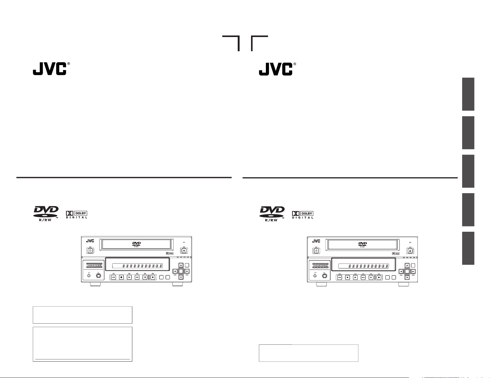
BD-X200
FWD PAUSE REC
BUSY
OPEN/CLOSE
TOP
MENU MENU
OPTION DV Y/C LINE
SET UP
AUDIO
CH1
CH2
TITLE
DOLBY DIGITAL
LPCMMPEG
CHAPTER
SET
BD-X200U
INSTRUCTIONS
DVD RECORDER
LLT0060-001A-C
For Customer Use :
Enter below the Serial No. which is located on the bottom
of the unit.
Retain this information for future reference.
Model No. BD-X200U
Serial No.
Thank you for purchasing this JVC product. Before operating
this unit, please read the instructions carefully to ensue the
best possible performance.
OPERATE
PHONES REV
STOP PLAY
DVD RECORDER
BD-X200
FWD PAUSE REC
BUSY
OPEN/CLOSE
TOP
MENU MENU
OPTION DV Y/C LINE
SET UP
AUDIO
CH1
CH2
TITLE
DOLBY DIGITAL
LPCMMPEG
CHAPTER
SET
BD-X200E
INSTRUCTIONS
BEDIENUNGSANLEITUNG
MANUEL D’INSTRUCTIONS
INSTRUCCIONES
ISTRUZIONI
DVD RECORDER
DVD-RECORDER
ENREGISTREUR DE DVD
GRABADORA DE DVD
MASTERIZZATORE DVD
Deutsch
English
Français
Español
Italiano
LLT0061-001A-C
Thank you for purchasing this JVC product. Before operating
this unit, please read the instructions carefully to ensue the
best possible performance.
Page 2
E
U
1. Read all of these instructions.
2. Save these instructions for later use.
3. All warnings on the product and in the operating instructions should be adhered to.
4. Unplug this appliance system from the wall outlet before cleaning. Do not use liquid cleaners or aerosol cleaners.
Use a damp cloth for cleaning.
5. Do not use attachments not recommended by the appliance manufacturer as they may cause hazards.
6. Do not use this appliance near water - for example, near a bathtub, washbowl, kitchen sink, or laundry tub, in a
wet basement, or near a swimming pool, etc.
7. Do not place this appliance on an unstable cart, stand, or table. The appliance may fall, causing
serious injury to a child or adult, and serious damage to the appliance.
Use only with a cart or stand recommended by the manufacturer, or sold with the appliance. Wall
or shelf mounting should follow the manufacturer’s instructions, and should use a mounting kit
approved by the manufacturer. An appliance and cart combination should be moved with care.
Quick stops, excessive force, and uneven surfaces may cause the appliance and cart combination
to overturn.
8. Slots and openings in the cabinet and the back or bottom are pro-vided for ventilation, and to insure reliable
operation of the appliance and to protect it from overheating, these openings must not be blocked or covered. The
openings should never be blocked by placing the appliance on a bed, sofa, rug, or other similar surface.
This appliance should never be placed near or over a radiator or heat register. This appliance should not be
placed in a built-in installation such as a bookcase unless proper ventilation is provided.
9. This appliance should be operated only from the type of power source indicated on the marking label. If you are
not sure of the type of power supplied to your home, consult your dealer or local power company. For appliance
designed to operate from battery power, refer to the operating instructions.
10. This appliance system is equipped with a 3-wire grounding type plug (a plug having a third (grounding) pin). This
plug will only fit into a grounding-type power outlet. This is a safety feature. If you are unable to inser t the plug into
the outlet, contact your electrician to replace your obsolete outlet. Do not defeat the safety purpose of the grounding
plug.
11. For added protection for this product during a lightning storm, or when it is left unattended and unused for long
periods of time, unplug it from the wall outlet and disconnect the antenna or cable system. This will prevent
damage to the product due to lightning and power-line surges.
12. Do not allow anything to rest on the power cord. Do not locate this appliance where the cord will be abused by
persons walking on it.
13. Follow all warnings and instructions marked on the appliance.
14. Do not overload wall outlets and extension cords as this can result in fire or electric shock.
15. Never push objects of any kind into this appliance through cabinet slots as they may touch dangerous voltage
points or short out parts that could result in a fire or electric shock. Never spill liquid of any kind on the appliance.
16. Do not attempt to service this appliance yourself as opening or removing covers may expose you to dangerous
voltage or other hazards. Refer all servicing to qualified service personnel.
17. Unplug this appliance from the wall outlet and refer servicing to qualified service personnel under the following
conditions:
a. When the power cord or plug is damaged or frayed.
b. If liquid has been spilled into the appliance.
c. If the appliance has been exposed to rain or water.
d. If the appliance does not operate normally by following the operating instructions. Adjust only those controls
that are covered by the operating instructions as improper adjustment of other controls may result in damage
and will often require extensive work by a qualified technician to restore the appliance to normal operation.
e. If the appliance has been dropped or the cabinet has been damaged.
f. When the appliance exhibits a distinct change in performance - this indicates a need for service.
18. When replacement parts are required, be sure the service technician has used replacement parts specified by the
manufacturer that have the same characteristics as the original part. Unauthorized substitutions may result in fire,
electric shock, or other hazards.
19. Upon completion of any service or repairs to this appliance, ask the service technician to perform routine safety
checks to determine that the appliance is in safe operating condition.
PORTABLE CART WARNING
(symbol provided by RETAC)
S3125A
IMPORTANT SAFEGUARDS
I
I
Supplement
This apparatus is designed for rack mounting or is used close to other apparatus.
In order to keep the best performance and furthermore for electromagnetic compatibility we recommend to use cables
not exceeding the following lengths:
Port Cable Length
Y/C Coaxial cable 10 meters
VIDEO LINE Coaxial cable 10 meters
AUDIO LINE Shielded cable 10 meters
REMOTE (9P) Shielded Twist Pair cable 5 meters
DV Shielded Twist Pair cable 4 meters
PHONES Shielded Twist Pair cable 5 meters
MIC Shielded Twist Pair cable 5 meters
LAN Shielded Twist Pair cable 10 meters
USB Shielded Twist Pair cable 5 meters
DC 19V Shielded cable 1.2 meters
The inrush current of this apparatus is 19 amperes.
Caution:
5 Where there are strong electromagnetic waves or magnetism, for example near a radio or TV transmitter, transformer,
motor, etc., the picture and sound may be disturbed. In such a case, please keep the apparatus away from the
sources of the disturbance.
Page 3
E
U
Safety Precautions
CAUTION: TO REDUCE THE RISK OF ELECTRIC SHOCK.
DO NOT REMOVE COVER (OR BACK).
NO USER-SERVICEABLE PARTS INSIDE.
REFER SERVICING TO QUALIFIED SERVICE PERSONNEL.
The lightning flash wish arrowhead symbol, within an equilateral
triangle is intended to alert the user to the presence of uninsulated
“dangerous voltage” within the product's enclosure that may be of
sufficient magnitude to constitute a risk of electric shock to persons.
The exclamation point within an equilateral triangle is intended to
alert the user to the presence of important operating and
maintenance (servicing) instructions in the literature accompanying
the appliance.
RISK OF ELECTRIC SHOCK
DO NOT OPEN
CAUTION
WARNING:
TO REDUCE THE RISK OF FIRE OR ELECTRIC
SHOCK, DO NOT EXPOSE THIS APPLIANCE TO
RAIN OR MOISTURE.
This unit should be used with 120 V AC only.
CAUTION:
To prevent electric shocks and fire hazards, DO NOT
use any other power source.
AVERTISSEMENT:
POUR EVITER LES RISQUES D’INCENDIE OU
D’ELECTRO-CUTION, NE PAS EXPOSER
L’APPAREIL A L’HUMIDITE OU A LA PLUIE.
Ce magnétoscope ne doit être utilisé que sur du
courant alternatif en 120V.
ATTENTION:
Afin d’éviter tout resque d’incendie ou
d’électrocution, ne pas utiliser d’autres sources
d’alimentation électrique.
Note:
The rating plate (serial number plate) is on the bottom of the unit.
INFORMATION
This equipment has been tested and found to comply with the
limits for a Class A digital device, pursuant to Part 15 of the FCC
Rules. These limits are designed to provide reasonable
protection against harmful interference when the equipment is
operated in a commercial environment. This equipment
generates, uses, and can radiate radio frequency energy and, if
not installed and used in accordance with the instruction manual,
may cause harmful interference to radio communications.
Operation of this equipment in a residential area is likely to cause
harmful interference in which case the user will be required to
correct the interference at his own expense.
CAUTION
CHANGES OR MODIFICATIONS NOT APPROVED BY JVC
COULD VOID USER’S AUTHORITY TO OPERATE THE
EQUIPMENT.
This Class A digital apparatus meets all requirements of the
Canadian Interference-Causing Equipment Regulations.
Cet appareil numérique de la classe A respecte toutes les
exigences du Reglement sur le matériel brouilleur du Canada.
REMARQUE:
La plaque d’identification (numéro de série) se trouve sur le
panneau arrière de l’appareil.
WARNING:
The battery used in the BD-X200U must be replaced by a JVC
authorized service dealer only.
ATTENTION: POUR EVITER TOUT RISQUE D’ELECTROCUTION
NE PAS OUVRIR LE BOITER.
ACCUNE PIECE INTERIEURE N
’EST.
A REGLER PAR L’UTILISATEUR.
SE REFERER A UN AGENT QUALIFIE EN CAS DE PROBLEME.
Le symbole de l’éclair à l’intérieur d’un triangle équilatéral est
destiné à alerter l’utilisateur sur la présence d’une “tension
dangereuse” non isolée dans le boîtier du produit. Cette tension
est suffisante pour provoquer l
’électrocution de personnes.
Le point d’exclamation à l’intérieur d’un triangle équilatéral est
destiné à alerter l’utilisateur sur la présence d’opérations
d’entretien importantes au sujet desquelles des renseignements
se trouvent dans le manuel d
’instructions.
*Ces symboles ne sont utilis
és qu’aux Etats-Unis.
RISQUE D’ELECTROCUTION
NE PAS OUVRIR
ATTENTION
II
English
IMPORTANT (In the United Kingdom)
Mains Supply (AC 230 V `)
WARNING – THIS APPARATUS
MUST BE EARTHED
The wires in this mains lead are coloured in accordance
with the following code;
GREEN-and-YELLOW : EARTH
BLUE : NEUTRAL
BROWN : LIVE
As the colours of the wires in the mains lead of this
apparatus may not correspond with the coloured
markings identifying the terminals in your plug, proceed
as follows.
The wire which is coloured GREEN-AND-YELLOW
must be connected to the terminal in the plug which is
marked with the letter E or by the safety earth symbol
or coloured GREEN or GREEN-AND-YELLOW. The
wire which is coloured BLUE must be connected to the
terminal which is marked with the letter N or which is
coloured BLACK. The wire which is coloured BROWN
must be connected to the terminal which is marked
with the letter L or coloured RED.
II
SAFETY PRECAUTIONS
Warning Notice
FOR YOUR SAFETY (Australia)
1. Insert this plug only into effectively earthed three-
pin power outlet.
2. If any doubt exists regarding the earthing, consult a
qualified electrician.
3. Extension cord, if used, must be three-core correctly
wired.
POWER SYSTEM
Connection to the mains supply
This unit operates on voltage of 220 V to 240 V AC, 50
Hz/60 Hz.
WARNING:
TO REDUCE THE RISK OF FIRE OR ELECTRIC
SHOCK, DO NOT EXPOSE THIS APPLIANCE TO
RAIN OR MOISTURE.
CAUTION
To prevent electric shock, do not open the cabinet. No
user serviceable parts inside. Refer servicing to
qualified service personnel.
Note:
The rating plate and the safety caution are on the
bottom of the unit.
The OPERATE button does not completely shut off
mains power from the unit, but switches operating
current on and off.
WARNING
It should be noted that it may be unlawful to re-record
pre-recorded tapes, records, or discs without the
consent of the owner of copyright in the sound or video
recording, broadcast, or cable programme and in any
literary, dramatic, musical or artistic work embodied
therein.
WARNING
This is a Class A product. In a domestic environment
this product may cause radio interference in which case
the user may be required to take adequate measures.
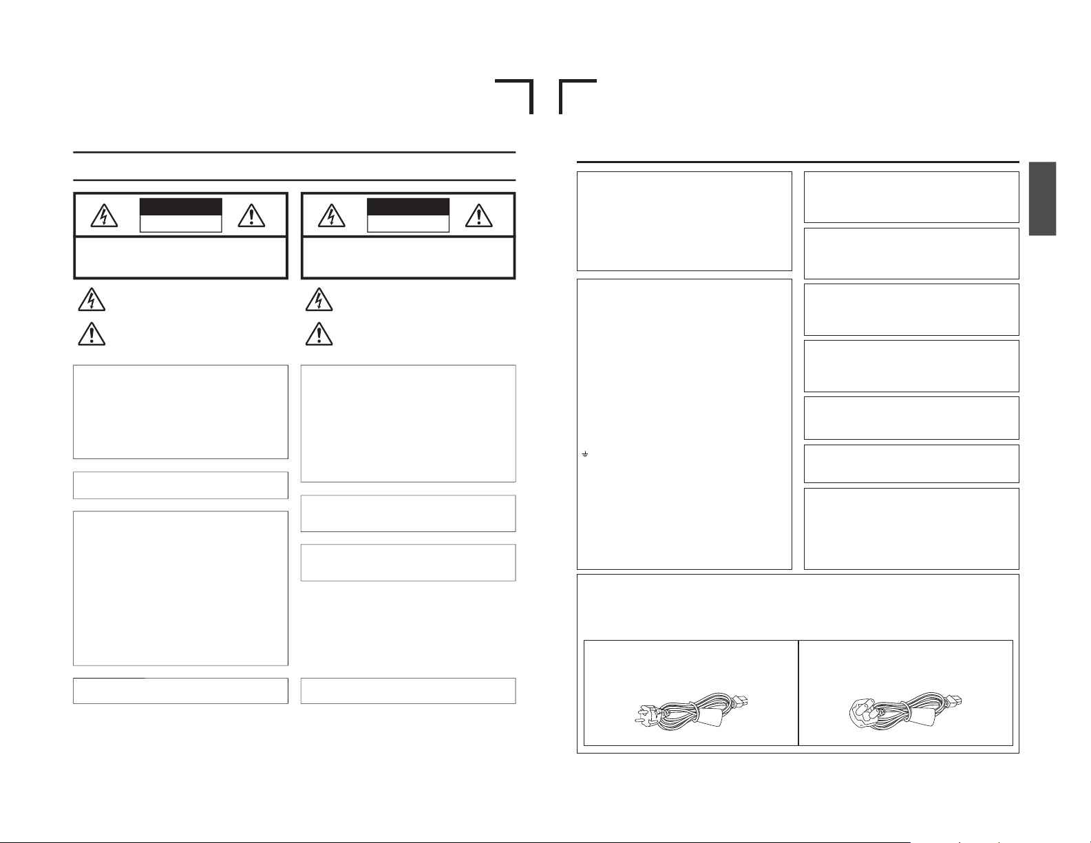
Caution for AC Mains Lead
FOR YOUR SAFETY PLEASE READ THE FOLLOWING TEXT CAREFULLY.
This product is equipped with 2 types of AC cable. One is for continental Europe, etc. and the other one is only for
U.K.
Appropriate mains cable must be used in each local area, since the other type of mains cable is not suitable.
FOR CONTINENTAL EUROPE, ETC.
Not to be used in the U.K.
FOR U.K. ONLY
If the plug supplied is not suitable for your socket outlet,
it should be cut off and appropriate one fitted.
Page 4

2
Thank you for purchasing
this JVC BD-X200 DVD Recorder.
Main Features
● Recording of DVD-R and DVD-RW (video mode only).
● Composite video, YC separate, and DV signals are supported
as video inputs; furthermore, analog or DV signals are
supported as audio inputs.
● A keyboard and mouse can be used as an alternative to front
panel buttons.
● When the BD-X200 is connected to an RS-422A compatible
VCR, RS-422 control can be used to carry out synchronous
recording of the VCR’s video and audio to a DVD.
● Synchronous recording of video and audio from a DV camera
or video player to a DVD can also be carried out.
● The DV IN/OUT terminal can be used to record audio and
video from a non-linear editor to a DVD.
● The title and chapter menus can be created either
automatically or manually.
● This DVD recorder features a LAN terminal. Accordingly, two
of these recorders can be connected using LAN (CAT 5) cables
to perform master-to-receiver dubbing.
Trademarks & Copyrights
●
, Dolby and the Double “D” symbols are
trademarks of Dolby Laboratories.
● The copying, broadcasting, screening, or rental of
copyrighted material without the authorization of the
copyright holder is prohibited by law.
Copyright Protection Technology
This DVD recorder utilizes copyright protection technology
and is protected by US patents and intellectual property as
owned by Macrovision and other copyright holders. The
permission of Macrovision is required in order to use this
copyright protection technology, and except in situations
where special permission has been granted by that
company, said technology is restricted to domestic usage
and for certain other viewing purposes. The disassembly
and/or modification of this DVD recorder is also prohibited.
Copyrights
● The recording, dubbing, or playing of software containing
a copyright protection signal is not possible on this DVD
recorder.
● The usage of audio or video discs created using this DVD
recorder either for financial gain or in broadcasting for
widespread viewing may result in the legally-enforceable
rights of the copyright holder being infringed.
● Unless the permission of the copyright holder has been
obtained, audio or video discs created using this DVD
recorder are to be used for personal enjoyment only.
Contents
Introduction
Overview of BD-X200 Functions ......................................................................................................................................... 4
Precautions for DVD Recorder Use..................................................................................................................................... 5
Precautions for Disc Usage ................................................................................................................................................. 6
Details Regarding Discs ...................................................................................................................................................... 7
Component Names & Functions
F
ront Panel .......................................................................................................................................................................... 9
Rear Panel......................................................................................................................................................................... 12
LCD Display and On-Screen Content
LCD Display....................................................................................................................................................................... 14
On-Screen Content ........................................................................................................................................................... 16
Status Messages ......................................................................................................................................................... 16
Disc Status ................................................................................................................................................................... 18
Event Messages .......................................................................................................................................................... 19
Alarm Messages .......................................................................................................................................................... 20
Preparation
Signal Connections ........................................................................................................................................................... 21
Power Connections ............................................................................................................................................................ 23
Tu r ning the Power On & Off............................................................................................................................................... 24
Inserting & Removing Discs .....................................................................................................
......................................... 25
Using a Keyboard & Mouse ............................................................................................................................................... 26
Setting & Displaying the Date & Time................................................................................................................................ 27
3
Settings & Controls for Recording
DVD Recording.................................................................................................................................................................. 29
Preparing a Disc for Recording ......................................................................................................................................... 30
Pre-Recording Settings ..................................................................................................................................................... 31
Selecting & Confirming Input Signals ................................................................................................................................ 32
Setting the Encoding Format for Audio & Video ..................................................................................
.............................. 33
Adjusting of Audio Recording Levels ................................................................................................................................. 35
Checking the Video Input .................................................................................................................................................. 36
Selecting Styles for Title & Chapter Menu ......................................................................................................................... 37
Recording
Recording Sequence ......................................................................................................................................................... 38
Recording with the Front Panel ......................................................................................................................................... 39
Inserting Chapter Marks Manually or Automatically ..............................................................................
...................... 40
Using a Keyboard & Mouse to Control Recording ..................................................................................
........................... 41
Finalizing (for playback on this and other DVD players) .................................................................................................... 42
Title & Chapter Menu Settings
BD-X200 Title & Chapter Menus ....................................................................................................................................... 43
Selecting and Changing Styles for Title & Chapter Menus................................................................................................ 44
Easymenu: Freeware for Editing Menu Templates ............................................................................................................ 46
Changing Chapter Menus (THUMBNAIL EDIT screen) .................................................................................................... 47
Changing & Naming Thumbnails for Chapter Menus ........................................................................................................ 48
Changing & Checking Chapter Menu Styles ..................................................................................................................... 50
Ending the Editing of Chapter Menus ................................................................................................................................ 52
Changing & Checking Title Menu Styles & Names............................................................................................................ 53
Playback
Playing Discs ..................................................................................................................................................................... 57
Fast & Slow Playback ........................................................................................................................................................ 58
Playing the Previous or Next Chapter................................................................................................................................ 58
Synchronous Recording
Recording Playback Signals From a VCR with RS-422A .................................................................................................. 59
Recording Playback Signals From a DV Camera or VCR ................................................................................................. 63
Recording Video & Audio From a Non-Linear Editor ...............................................................................
.......................... 64
In, Out & Chapter Points from External Edit Lists.............................................................................................................. 68
Recording Operations Using a DV Camera Trigger ........................................................................................................... 69
DVD Dubbing
Dubbing DVDs Using the LAN Terminal ............................................................................................................................ 70
Setup Menu
Setup Menu Configuration .......................................................................................................
.......................................... 74
Setting the Setup Menu ..................................................................................................................................................... 75
Restoring to Default Settings ..................................................................................................
..................................... 75
Setup Menus ....................................................................................................................
................................................. 76
DISC MENU Screen .......................................................................................................................................................... 77
INPUT SELECT MENU screen ......................................................................................................................................... 77
SYSTEM MENU Screen .............................................................................................................
....................................... 78
PRESET STYLE MENU screen .......................................................................................................
................................. 79
RECORDER MENU Screen .............................................................................................................................................. 80
REMOTE MENU screen .............................................................................................................
....................................... 82
DISPLAY MENU screen .................................................................................................................................................... 83
CLOCK ADJUST MENU screen ........................................................................................................................................ 84
DUBBING screen .................................................................................................................
............................................. 84
NETWORK MENU Screen ................................................................................................................................................ 85
Others
Troubleshooting ................................................................................................................................................................. 85
Specifications .................................................................................................................................................................... 86
Page 5

4
Introduction
Overview of BD-X200 Functions
䡵Video and audio signals from this DVD recorder’s input terminals can be recorded to
DVD-R or DVD-RW (video mode only).
(☞ Page 29)
The types of signals that can be used are as follows.
Video: Composite video, YC separate, or DV signals (including audio)
Audio: Analog audio or DV signals (including video)
䡵A wide range of recording methods are supported. The appropriate method is to be
selected in accordance with the intended mode of use.
●
The REC, PAUSE, and STOP buttons on the front panel can be used for standard operations. (☞ Page 39)
● Recording operations can be carried out using the REC CONTROL panel. Furthermore, a keyboard and mouse can also be
used when recording via this panel. (
☞ Page 41)
●
The BD-X200 features an RS-422A terminal. When it is connected to an RS-422A compatible VCR, therefore, RS-422 control
can be used to carry out synchronous recording of the VCR’s video and audio to a DVD. (Various menu settings are required.)
Synchro-recording is carried out from the REMOTE CONTROL screen. (☞
Page 59)
●
When a digital video camera or a DV player is connected to the BD-X200 using a DV cable, and when this DVD recorder is
setup as the master device for DV control (using menu settings), synchronous recording of any video and/or audio signals
from the DV player can be carried out to a DVD. Synchro-recording is carried out from the REMOTE CONTROL screen. (
☞
Page 63)
●
The DV IN/OUT terminal can be used to record audio and video from a non-linear editor to a DVD. In such a case, the BDX200 must be setup as the control slave (using menu settings). The DVD recorder will be controlled by the non-linear editor
in this type of setup. (☞ Page 64)
䡵The title and chapter menus can be created either automatically or manually.
(☞ Page 43)
Five different patterns have been provided as display styles for the title and chapter menus. Each of these patterns is characterized
by different thumbnail characteristics (i.e., number, position, and size) and background images displayed on the title and
chapter menu screens.
When a display style is selected during the recording of content to a DVD, the BD-X200 will automatically create the title and
chapter menus in accordance with this style.
The PRESET STYLE MENU screen can be used to modify the thumbnail and background display characteristics of each of the
display styles.
In addition, the THUMBNAIL EDIT screen and the CHAPTER MENU EDIT screen can be used to modify the display style and
thumbnail images for chapter menus, and also to input chapter names and comments. The input of names or comments is
carried out using a keyboard connected to one of the recorder’s USB terminals.
The TITLE MENU EDIT screen can be used to modify the display style for the title menu and to enter title names.
䡵DVD dubbing can be carried out using the LAN terminal.
This terminal allows two BD-X200 DVD recorders to be connected using a LAN cable, and the recorders can then operate as
master and receiver devices during the dubbing of DVDs. (☞ Page 70)
䡵The BD-X200 can be used to play discs that it has created.
(☞ Page 57)
In this way, it is possible to inspect the content of discs finalized using this DVD recorder.
● Once a disc has been finalized, it can also be played on other DVD players.
5
Precautions for DVD Recorder Use
䡵 Storage & Usage Locations
The storage and usage of this DVD recorder in the following
types of location should be avoided.
● Areas at temperatures which deviate by a significant degree
above or below the permitted service temperature range
(i.e., 5°C to 35°C).
● Areas at humidities which deviate by a significant degree
above or below the permitted service humidity range (i.e.,
20% to 80% RH).
● Areas where a large amount of dust or sand is present.
● Areas where the DVD recorder may come into contact with
oily smoke or steam, such as in kitchens or in their
immediate vicinity.
● Areas that are unstable or where significant vibration occurs.
● Areas where condensation occurs readily.
● Areas where strong magnetic fields are generated by
transformers, motors, or the like.
● Areas where transceivers, mobile phones, and other
wireless-communication devices are present.
● Areas that are subjected to X-ray irradiation or where
corrosive gases are present. (This precaution must be
strictly observed.)
䡵 Handling
● Ensure that this DVD recorder is placed on a flat, horizontal
surface for use.
● Do not place heavy objects such as a monitor on top of the
DVD recorder.
● Do not insert foreign objects into the disc tray opening.
● Be careful not to get your fingers clamped when loading
the disc to prevent injury.
● Do not block the fan’s ventilation holes.
● Avoid knocking or dropping this DVD recorder.
● When the DVD recorder is to be moved, ensure that any
DVD it contains is removed in advance.
● If the DVD recorder is not to be used for an extended period
of time, please disconnect the AC adaptor to avoid wasting
electricity.
䡵 Cleaning the Exterior (with the power off)
Use a soft cloth when cleaning the outside of this DVD
recorder.
Do not use paint thinners or organic solvents as cleaning
agents.
Failure to observe these precautions can result in discoloration
or melting of exterior surfaces.
When stubborn dirt is present, wipe away using a cloth soaked
in a dilute neutral solvent.
䡵 Always use the AC adaptor provided with this DVD
recorder.
䡵 Always use the power cord provided with this DVD
recorder.
The usage of a different type of cord or a damaged cord can
result in the outbreak of fire or electric shocks.
䡵
The power cord or the AC adaptor supplied with this
DVD recorder should not be used with any other device.
䡵 Before connecting the BD-X200 to other devices,
turn those devices off and then carry out setup
procedures as described in the corresponding
user’s manuals.
䡵
The DVD drive unit is an expendable part. Although
the service life of the DVD drive unit differs depending
on the usage environment of the customer, replacement
every 1000 hours as a guide is recommended. (☞ Page
78 “TOTAL RECORDING TIME”)
Precautions Regarding Condensation
䡵Condensation
When cold water is poured into a glass and droplets of
water form on its outer surface, this moisture is referred
to as “condensation”.
䡵When condensation occurs
Condensation can cause water droplets to adhere to the
DVD recorder’s internal lens, thus making normal
operation impossible.
䡵Condensation occurs easily in the following situations,
and the appropriate care should be taken.
• When the DVD recorder is moved from a cold location
into a warm room.
• When the room containing the DVD is rapidly heated.
• When an air conditioner’s air duct is pointing straight at
the DVD recorder.
䡵In situations where it is likely that condensation will occur,
remove any DVD that may be present in the BD-X200
and then turn the power on. As the interior heats up,
condensation will be less likely to occur.
䡵
Condensation is a principal cause of the inability to play
discs and other similar problems. In this type of situation,
allow the DVD recorder to remain inactive with its power
on for several hours. If the problem persists after this
period of time has elapsed, contact either the store where
the BD-X200 was purchased or your nearest JVC
A
uthorized dealer.
Extended Periods of Inactivity
Performance may deteriorate over extended per iods of
inactivity; for this reason, the power should be turned on
and the DVD recorder should be operated at regular
intervals.
Compensation for Damaged Content
䡵JVC accepts no responsibility whatsoever for damages
incurred as a result of an inability to play or record audio
and video content in the rare event that this DVD recorder,
a DVD-R, or a DVD-RW fails to operate correctly.
䡵It is recommended that discs containing important content
be backed up at regular intervals (i.e., on a yearly basis).
Although digital signals do not deteriorate, storage
environments can have an effect on a disc’s aging
characteristics, and this may result in an inability to play
or record.
䡵If a disc should break, there will be no way to recover
data from it.
䡵Proper playback of discs recorded using this DVD recorder
on all devices is not guaranteed.
Page 6
6
Introduction
Precautions for Disc Usage
Care of Discs to Ensure High-Quality Playback
䡵Fingerprints, dust, or any other similar contamination of the surface of a disc can lead to distortion in the playback of recorded
video and audio. For this reason, it is good practice to wipe each disc with a soft cloth before use.
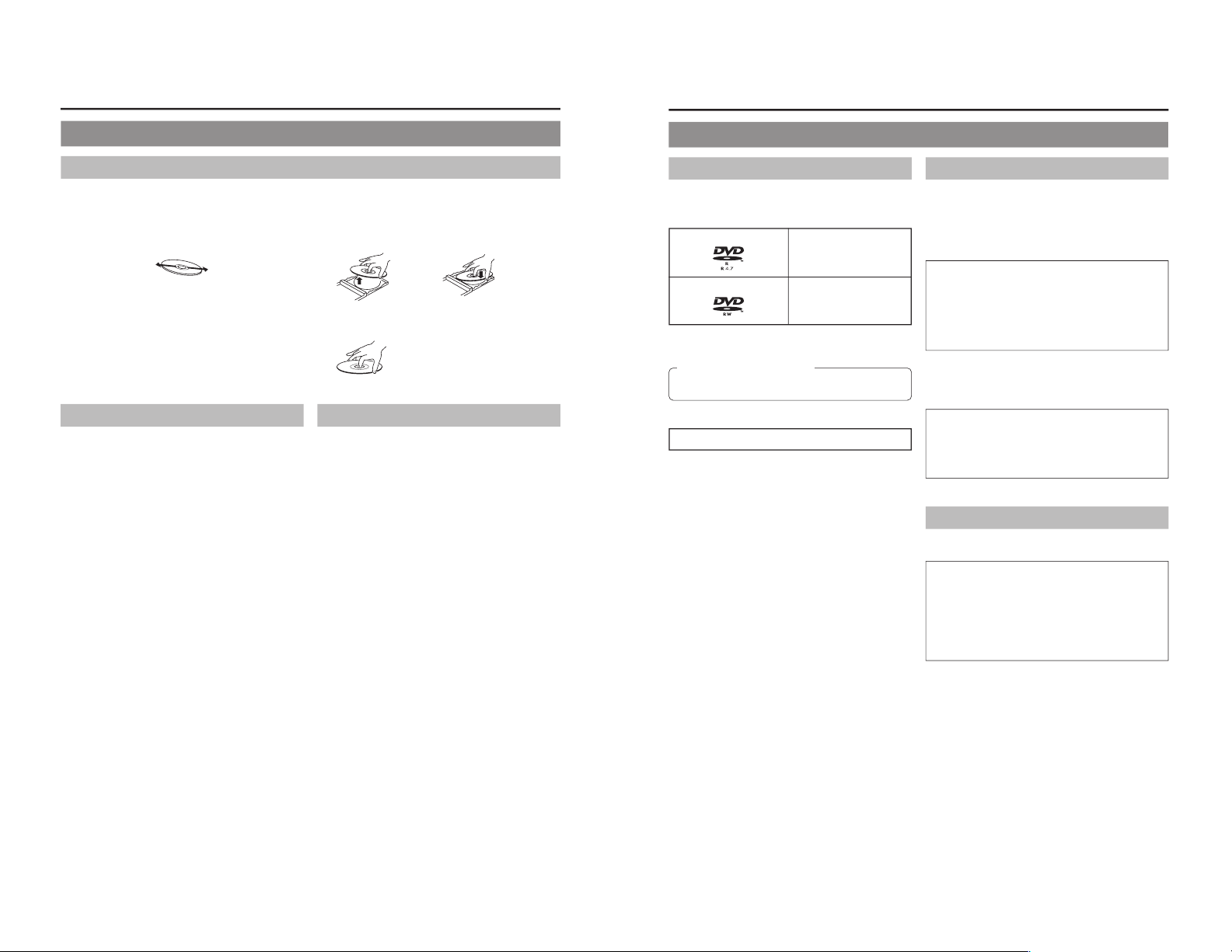
䡵 Looking After Discs
● Using a soft cloth, wipe the disc gently from the inside to
the outside.
● If stubborn dirt is present on the surface of a disc, wipe first
using a slightly wet cloth and then using a dry cloth.
● Paint thinners, organic solvents, analog record cleaning
agents, anti-static sprays, and the like must never be used.
Failure to observe this precaution can lead to discs being
permanently damaged.
䡵 Handling Discs
● Removing a disc ● Placing a disc in its case
● Correct method for holding a disc
Your hands or fingers should not
come into contact with the
recording surface when holding
a disc.
Additional Notes on Disc Handling
䡵Never wipe a disc using paint thinners, organic solvents,
alcohol, or record-cleaning fluid.
䡵Do not use disc protectors or scratch guards.
䡵Stickers and other types of paper label should not be applied.
䡵Do not use discs from which stickers or labels have been
removed.
䡵
Do not use discs on which illustrations or text has been printed
using a commercially-available label printer. First create a disc
using the unit before printing.
䡵The use of non-circular discs (i.e., heart or rectangular
shaped), warped discs, and cracked discs can lead to
breakage of the DVD recorder.
Storing Discs
䡵Avoid storing discs in any of the following locations.
• Areas with high levels of humidity or dust, or areas where
mold is present.
• Areas exposed to direct sunlight or close to heating
equipment.
•Vehicle interiors during summer months.
䡵Ta ke care to avoid dropping or knocking discs.
䡵Place discs in cases and stack these cases for storage.
䡵Discs can be deformed or cracked as a result of stacking,
leaning, or dropping when not inside a case.
7
Details Regarding Discs
Discs for Recording & Playback
The following shows the discs that can be recorded to and played
using this DVD recorder, in addition to the corresponding display
marks or logos.
DVD-R 12 cm: 4.7 GB
General Version 2.0
(video mode)
DVD-RW 12 cm: 4.7 GB
Version 1.1 or later
(video mode)
*
Certain characteristics and properties of DVD-Rs and DVDRWs can render them unsuitable for recording or playback.
Recommended manufacturers
DVD-R : JVC, Maxell, TDK 1×, 2×, 4×
DVD-RW : JVC, TDK 1
×, 2×
DVD-R & DVD-RW Details
DVD-R :
Only discs that conform with DVD-R Standard 2.0
(video mode) can be used.
DVD-RW : Discs of Version 1.1 or later can be used.
Although Version 1.1 of the DVD-RW Standards
allows the selection of either video mode or VR mode
for recording, this DVD recorder perfor ms recording
in video mode only.
*Version 1.0 of the DVD-RW Standards does not
support video-mode recording, and for this
reason, the corresponding discs cannot be used.
In terms of recording characteristics, DVD-R and DVD-RW (video
mode) differ as follows.
䡵 DVD-R
• Each disc can be recorded only one. Accordingly, these
discs are recommended for use in archiving or long-term
storage.
• Once a disc has been finalized, it can also be played on
other DVD players.
䡵 DVD-RW (video mode):
• After viewing a disc, all data can be erased and it can be
used to record new content.
• Once a disc has been finalized, it can also be played on
other DVD players.
Finalizing
When a DVD-R or a DVD-RW (video mode) has been finalized,
it can be played in the same way as any other DVD using a
standard DVD player. (
☞ Page 42)
䡵 Recording to unused sections of a disc and the
modification of titles or display styles can be carried
out as required before a disc is finalized.
• In the case of both DVD-Rs and DVD-RWs, it is impossible
to overwrite previously recorded content with new data,
even if the disc in question has not yet been finalized. The
deletion of specific sections of data is also impossible.
• Regardless of whether or not finalization has been carried
out, it will not be possible to use this DVD recorder to
record new content to a DVD-R or DVD-RW that has been
recorded using other devices.
䡵 Once a disc has been finalized, it can be used as a
standard DVD and its recorded audio and video can
be played on this and other DVD players.
•
After finalizing, a disc’s titles can be selected from the top
menu.
• Additional recording will not be possible after finalizing.
•
Although a finalized disc may in principle be played on
other DVD players, certain characteristics of the disc and
its recording conditions may make this impossible.
Playing Discs on the BD-X200
The BD-X200 is capable of playing any discs that it has created
and finalized.
●
The following conditions may occur when attempting to
play discs recorded using other devices on this DVD
recorder.
• Inability to play
• Block-type noise (i.e., mosaic)
• Interruptions in audio and/or video
•
Unintentional stopping during playback
● Commercially-available DVD-Videos and DVD-ROMs
cannot be used.
Page 7
8
Introduction
Details Regarding Discs (continued)
DVD Data Configuration
Generally speaking, the content recorded on a DVD is separated
into large units referred to as “titles”. A unique number called a
“title number” is assigned to each of these titles, and as a result,
any title can be immediately accessed using its title number. In
addition, each title can be divided into smaller units referred to
as “chapters”. Similarly, a unique number called a “chapter
number” is assigned to each of these chapters, and this allows
any chapter to be immediately accessed using its chapter
number.
Each recording made to a DVD-R or DVD-RW (video mode) is
stored as a single title. In this, each pressing of the STOP button
to leave Recording mode constitutes a different recording. (This
action is also referred to as
“title closing”.)
Whenever the PAUSE button is pressed to pause recording, a
chapter mark is inserted into the current title. It is also possible
to insert chapter marks to partition titles at the desired points by
pressing the REC button while recording. In addition, your BDX200 can also be used to automatically insert chapter marks at
regular intervals. (CHAPTER CREATION menu settings will be
required for this function.)
● Before a title is closed, it will be possible to modify the style
used for chapter menu display, to change the thumbnails used,
and to input thumbnail names.
● Before a disc is finalized, it will be possible to modify the style
used for the title menu and to input title names.
DVD-R or DVD-RW
Title 1
Chapter 1 Chapter 2 Chapter 3
Title 2
Chapter 1 Chapter 2
Region Codes
One of six numbers referred to as
“region codes” is assigned to
DVD content to control the global regions in which this content
may be viewed. If a DVD’s region code does not correspond to
the region code of the DVD player being used, it will not be
possible to play the disc.
● This DVD recorder assigns the region code “ALL” to the discs
that it records.
● It will not be possible to play discs to which region codes have
been assigned.
Screen Sizes
This DVD recorder is capable of recording video content for widescreen TVs (i.e., with a 16:9 aspect ratio).
In addition, signals for normal content with a 4:3 aspect ratio, for
squeezed content (i.e., where the left and right are compressed),
and for letterbox content (i.e., where the top and bottom of the
screen are black) can be recorded as is.
● Thumbnail creation method for use in the title/chapter menu
during wide-signal input can be selected in THUMBNAIL
FORM of the RECORDER (2/2) menu screen. (☞ Page 81)
9
Notes
● Do not push the disc tray as it is opening or closing.
● Do not place objects other than discs on the disc
tray.
● Do not press down on the disc tray
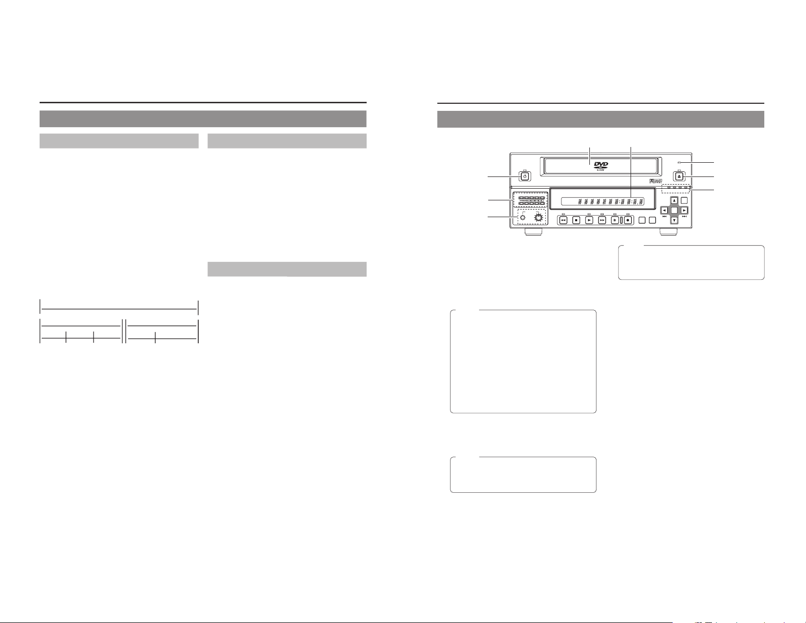
Component Names & Functions
Front Panel
OPERATE
PHONES REV
STOP PLAY
DVD RECORDER
BD-X200
FWD PAUSE REC
BUSY
OPEN/CLOSE
TOP
MENU MENU
OPTION DV Y/C LINE
SET UP
AUDIO
CH1
CH2
TITLE
DOLBY DIGITAL
LPCMMPEG
CHAPTER
SET
1
5
8
62
7
3
4
1
OPERATE button and indicator
● This button is used to turn on the DVD recorder and to
make it ready for use. When pressed a second time, this
button turns off the DVD recorder.
● The indicator’s lighting condition depends on the condition
of the DVD recorder and can be one of the following.
Lit in green : The DVD recorder’s power is on.
Lit in red : The DVD recorder’s power is off.
Flashing in red : An error has occurred.
2
Disc tray
The purpose of the disc tray is to hold DVDs.
This tray opens automatically when the OPEN/CLOSE button
is pressed. In addition, the OPEN/CLOSE button can be
pressed again to close the tray.
3
BUSY indicator
This indicator flashes when the DVD recorder is in Recording
Pause mode or when it is performing time-consuming
operations such as title closing, finalizing, and erasing. None
of the DVD recorder’s buttons will have any effect if pressed
while the BUSY indicator is flashing.
4
OPEN/CLOSE button and indicator
This button is used to open and close the disc tray.
In addition, the OPEN/CLOSE indicator is lit up while the disc
tray is opening, and also when it is open.
5
Audio level indicator
These meters are used to indicate the current level of audio
on Channel 1 and Channel 2.
Specifically, the audio level meters indicate the audio recording
levels when the DVD recorder is in Recording mode, and the
audio playback levels when it is in Playback mode.
(Adjustment of the audio recording levels: ☞
Page 35.)
6
LCD display
The LCD display is used to present important information.
During recording or playback, for example, the title, chapter
number, and elapsed time are indicated on the LCD display.
(☞ Page 14 for more details.)
7
Video input indicators
䡵 OPTION indicator
This indicator is lit up or flashes when INPUT SELECT
from the INPUT SELECT MENU screen has been set to
OPTION. (This setting cannot be carried out using the DVD
recorder alone.)
䡵 DV indicator
This indicator is lit up or flashes when INPUT SELECT
from the INPUT SELECT MENU screen has been set to
DV. Specifically, the indicator is lit up when an input signal
is present, and it flashes when no signal is present.
䡵 Y/C indicator
This indicator is lit up or flashes when INPUT SELECT
from the INPUT SELECT MENU screen has been set to
Y/C. Specifically, the indicator is lit up when an input signal
is present, and it flashes when no signal is present.
䡵 LINE indicator
This indicator is lit up or flashes when INPUT SELECT
from the INPUT SELECT MENU screen has been set to
LINE. Specifically, the indicator is lit up when an input signal
is present, and it flashes when no signal is present.
8
Phones jack and volume adjuster
The phones jack allows headphones to be connected to the
DVD recorder for monitoring of audio levels; in addition, the
headphone volume can be adjusted using the volume adjuster.
Note that this adjuster has no effect on the actual recording
levels.
Note
The OPEN/CLOSE button will have no effect if pressed
while the DVD recorder is in either Recording or
Recording Pause mode. This is also the case when
performing finalizing, erasing, or dubbing.
Notes
● The OPERATE button will have no effect if pressed
while the DVD recorder is in either Recording or
Recording Pause mode. This is also the case when
performing finalizing, erasing, or dubbing.
● The DVD recorder continues to use a small amount
of power even after it has been turned off using the
OPERATE button. If it will not be used for an extended
period of time, please disconnect the AC adaptor to
avoid wasting electricity.
● Do not disconnect the DC cord or power cord when
in Operate On mode as this can result in the DVD
recorder being damaged.
● Malfunction may occur when switching to OPERATE
ON while pressing a key on a connected USB
keyboard.
Page 8
10
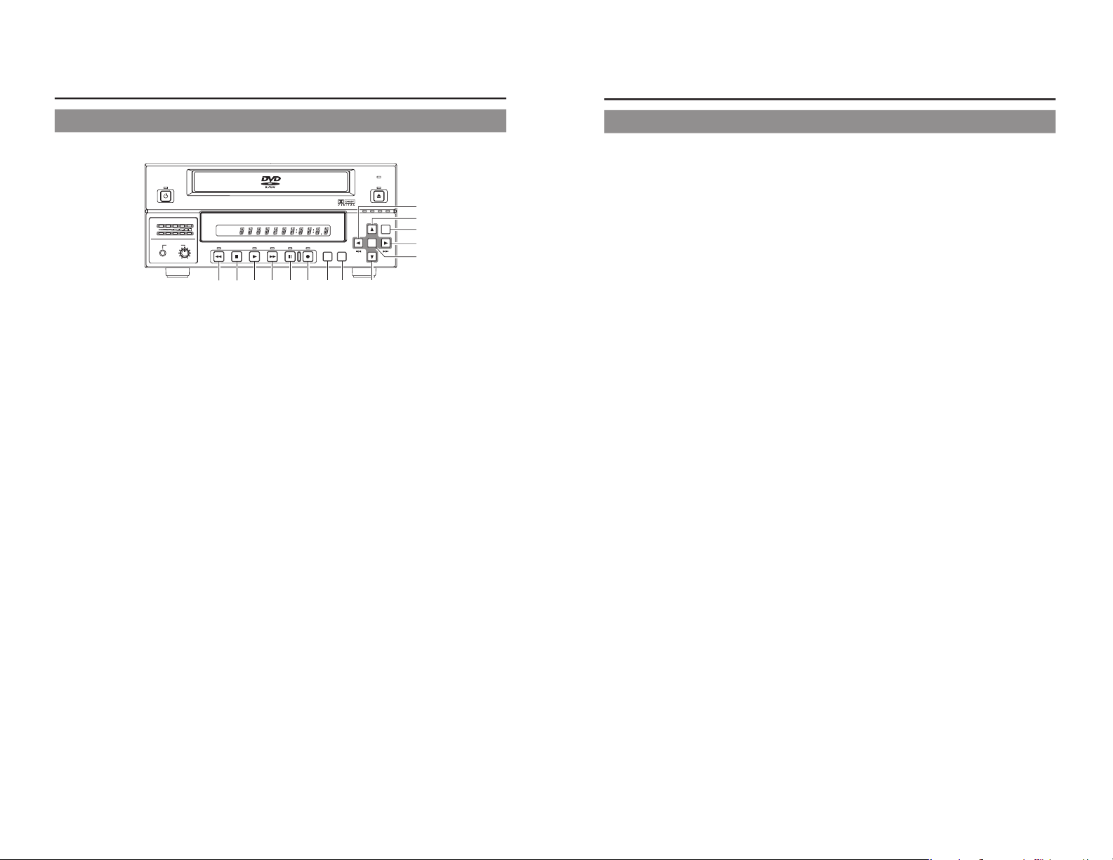
Component Names & Functions
Front Panel (continued)
OPERATE
PHONES REV
STOP PLAY
DVD RECORDER
BD-X200
FWD PAUSE REC
BUSY
OPEN/CLOSE
TOP
MENU MENU
OPTION DV Y/C LINE
SET UP
AUDIO
CH1
CH2
TITLE
DOLBY DIGITAL
LPCMMPEG
CHAPTER
SET
9
REV button and indicator
● When this button is pressed in Playback or Fast-Forward
Play mode, the DVD recorder switches to fast-reverse play.
If pressed again during fast-reverse play, the REV button
toggles the speed of fast-reverse between ×3 and
×15.
● When this button is pressed in Still or Slow-Forward Play
mode, the DVD recorder switches to slow-reverse play. If
pressed again during slow-reverse play, the REV toggles
the speed of slow-reverse between ×0.5 and
×0.06.
● The REV indicator is lit up during fast-reverse and slow-
reverse play.
0
STOP button
● This button has the following effect when pressed in
Recording or Recording Pause mode.
If EDIT MENU from the SYSTEM MENU screen is set to
DISABLE, the DVD recorder stops recording (i.e., it
performs title closing).
If EDIT MENU from the SYSTEM MENU screen is set to
ENABLE, the DVD recorder stops recording and the
THUMBNAIL EDIT screen is displayed. It will then be
possible to modify the chapter menu.
● When the STOP button is pressed in Playback mode, the
D
VD recorder stops playback.
!
PLAY button and indicator
● If this button is pressed together with the REC button while
a recordable disc is inserted into the DVD recorder,
recording will be started.
● When the PLAY button is pressed in Recording Pause
mode, the DVD recorder restarts recording.
● If a finalized disc has been inserted into the DVD recorder,
pressing of this button will start playback.
● The PLAY indicator is lit up in Recording and Playback
modes.
@
FWD button and indicator
● When this button is pressed in Playback or Fast-Reverse
Play mode, the DVD recorder switches to fast-forward play.
If pressed again during fast-forward play, the FWD button
toggles the speed of fast-forward between ×3 and
×15.
● When this button is pressed in Still or Slow-Reverse Play
mode, the DVD recorder switches to slow-forward play. If
pressed again during slow-forward play, the FWD toggles
the speed of slow-forward between ×0.5 and ×0.06.
● The FWD indicator is lit up during fast-forward and slow-
forward play.
#
PAUSE button and indicator
● If this button is pressed during recording, the DVD recorder
switches to Recording Pause mode. A chapter mar k is
inserted at the corresponding point.
● If this button is pressed during playback, the DVD recorder
s
witches to Still mode and freezes playback. If the PAUSE
button is then pressed again in Still mode, the DVD recorder
will advance playback by a single field.
● The PAUSE indicator is lit up in Recording Pause and Still
modes.
$
REC button and indicator
● If this button is pressed together with the PLAY button in
Stop mode, recording will be started.
• If the current disc is blank or title closing has been carried
out, a new title will be created and recording will start at
Chapter 1.
● When this button is pressed during recording, a new chapter
will be setup within the continuous video data.
● If this button is pressed and held for more than 2 seconds
while the DVD recorder is stopped or inserted with no disc,
input signal encoded/decoded in MPEG will be output via
the VIDEO OUT terminal on the rear panel. This will continue
for as long as the button is held, and it allows the DVD
recording quality to be confirmed. Audio will be muted at
this time.
●
The REC indicator is lit up in Recording and Recording
Pause modes.
%
TOP MENU button
If this button is pressed while the DVD recorder is in a playback
condition, the current DVD’s top menu (or title menu) will be
displayed on the monitor screen.
If the DVD does not contain a title menu, nothing will be
displayed when the TOP MENU button is pressed.
^
MENU button
If this button is pressed while the DVD recorder is in a playback
condition, the chapter menu for the currently selected title
will be displayed on the monitor screen.
If the DVD title does not contain a chapter menu, nothing will
be displayed when the MENU button is pressed.
90!@#$ %^
(
)
*
&
⁄
¤
11
&
SET UP button
●
This button can be pressed to display the Setup Menu on
the monitor. A wide range of different menu settings can
then be made via the Setup Menu. (☞ Page 74)
In addition, the SET UP button can be pressed again to
hide the Setup Menu.
● If the SET UP button is pressed in Recording or Recording
Pause mode, setting data relevant to recording (i.e., video
bit rate and audio encoding format) will be displayed onscreen. In addition, the SET UP button can be pressed again
to hide this information.
*
[6] button
● This button is used to select menu items or setting values
when the Setup Menu is displayed.
● If a title menu or chapter menu is displayed, this button can
be used to select a menu number for playback. Specifically,
pressing of this button moves the selection position upward.
●
The 6 button can be used to adjust the audio recording
levels when the DVD recorder is stopped or in Recording
Pause mode.
• If AUDIO REC VOLUME MODE from the RECORDER
MENU (2/2) screen is set to BOTH and this button is
pressed while either the 8
or t button is being held, the
audio recording levels for both Channel 1 and Channel 2
will increase.
• If AUDIO REC VOLUME MODE from the RECORDER
MENU (2/2) screen is set to INDEPENDENCE and this
button is pressed while the 8 button is being held, the
audio recording level for Channel 1 will increase. Similarly,
if the 6 button is pressed while the t b
utton is being
held, the audio recording level for Channel 2 will increase.
(
[7] button
● This button is used to select menu items or setting values
when the Setup Menu is displayed.
●
If a title menu or chapter menu is displayed, this button can
be used to select a menu number for playback. Specifically,
pressing of this button moves the selection position
downward.
● The 7 button can be used to adjust the audio recording
levels when the DVD recorder is stopped or in Recording
P
ause mode.
• If AUDIO REC VOLUME MODE from the RECORDER
MENU (2/2) screen is set to BOTH and this button is
pressed while either the 8 or t button is being held, the
audio recording levels for both Channel 1 and Channel 2
will decrease.
•
If AUDIO REC VOLUME MODE from the RECORDER
MENU (2/2) screen is set to INDEPENDENCE and this
button is pressed while the 8
button is being held, the
audio recording level for Channel 1 will decrease. Similarly,
if the 7 button is pressed while the
t button is being
held, the audio recording level for Channel 2 will decrease.
)
[8] button
● If a title menu or chapter menu is displayed, this button can
be used to select a menu number for playback. Specifically,
pressing of this button moves the selection position to the
left.
● This button can be pressed while the DVD recorder is
playing to move playback to the start of the current chapter.
● The 8 button can be used to adjust the audio recording
levels when the DVD recorder is stopped or in Recording
Pause mode.
• If AUDIO REC VOLUME MODE from the RECORDER
MENU (2/2) screen is set to INDEPENDENCE and either
the 6 or 7 button is pressed while this button is being
held, the audio recording level for Channel 1 will be
adjusted accordingly.
• If AUDIO REC VOLUME MODE from the RECORDER
MENU (2/2) screen is set to BOTH and either the 6 or
7
button is pressed while this button is being held, the audio
recording levels for both Channel 1 and Channel 2 will be
adjusted accordingly.
• If this button is pressed together with the t
button, the
audio recording levels will be returned to their default
settings (i.e., unity gain).
⁄
[t] button
● If a title menu or chapter menu is displayed, this button can
be used to select a menu number for playback. Specifically,
pressing of this button moves the selection position to the
right.
● This button can be pressed while the DVD recorder is
playing to move playback to the start of the next chapter.
● The t
button can be used to adjust the audio recording
levels when the DVD recorder is stopped or in Recording
Pause mode.
• If AUDIO REC VOLUME MODE from the RECORDER
MENU (2/2) screen is set to INDEPENDENCE and either
the 6 or 7 button is pressed while this button is being
held, the audio recording level for Channel 2 will be
adjusted accordingly.
• If AUDIO REC VOLUME MODE from the RECORDER
MENU (2/2) screen is set to BOTH and either the 6
or 7
b
utton is pressed while this button is being held, the audio
recording levels for both Channel 1 and Channel 2 will be
adjusted accordingly.
• If this button is pressed together with the 8
button, the
audio recording levels will be returned to their default
settings (i.e., unity gain).
¤
SET button
● This button is used to confirm the selection of menu items
or setting values when the Setup Menu is displayed.
● When this button is pressed during normal screen display,
the counter from the DVD recorder
’s LCD display will switch
to display of either the elapsed recording/playback time or
the remaining disc/title time.
Page 9
12
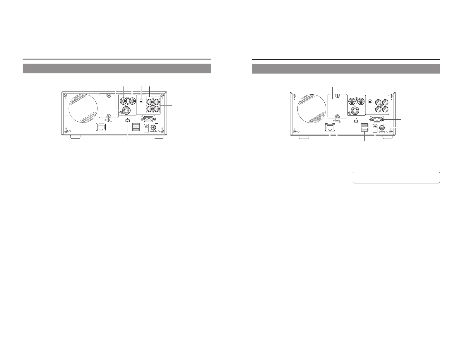
Component Names & Functions
Rear Panel
VIDEO AUDIO
ININOUT
IN
OUT
CH1
CH2
REMOTE
USB
DV IN/OUT
SIGNAL
LAN
GND
DC 19V
4dB
8dB
INPUT
LEVEL
LINE
Y/C
1
VIDEO LINE IN terminal (BNC)
This terminal allows composite video signals to be input to
the DVD recorder.
In order to select these signals for input, set INPUT SELECT
from the INPUT SELECT MENU screen to LINE.
● SETUP from the SYSTEM MENU screen should be set in
accordance with whether or not this input signal is a setup
signal.
(U-model only)
2
VIDEO Y/C IN terminal (4-pin)
This terminal allows YC separate video signals to be input to
the DVD recorder.
In order to select these signals for input, set INPUT SELECT
from the INPUT SELECT MENU screen to Y/C.
● SETUP from the SYSTEM MENU screen should be set in
accordance with whether or not this input signal is a setup
signal. (U-model only)
● This terminal’s specification (i.e., S1 or S2) can be selected
using Y/C TERMINAL MODE from the RECORDER MENU
(2/2) screen.
3
VIDEO LINE OUT terminal (BNC)
This terminal is used to connect the DVD recorder to a monitor.
● When the DVD recorder is in Stop or Recording mode, the
video input signal is output on the E-E screen as a
composite video signal.
● If the REC button is pressed and held for at least 2 seconds
while the DVD recorder is stopped, the input signal will be
subjected to MPEG encode/decode processing and output
via the VIDEO LINE OUT terminal. This will continue for as
long as the REC button is held, and it allows the DVD
recording quality to be confirmed.
● Playback from the DVD is output as a composite signal
when in Playback mode.
● The Setup Menu, title menu, chapter menus, and other
setting and control screens are displayed on the monitor
connected to this terminal.
●
Status and alarm information is also displayed on-screen.
(The DISPLAY MENU screen can be used to indicate which
items are to be displayed.)
4
AUDIO INPUT LEVEL switch
This switch is used to set the standard level for audio input.
+4dB : The standard level is set to +4 dB.
–8dB : The standard level is set to –8 dB.
12345
6
7
5
AUDIO IN terminals (RCA
× 2)
These terminals allow analog audio signals to be input to the
DVD recorder.
●
In order to select these signals for input, set INPUT SELECT
from the INPUT SELECT MENU screen to LINE or Y/C.
6
AUDIO OUT terminals (RCA × 2)
These terminals allow analog audio signals to be output from
the DVD recorder.
● When the DVD recorder is in Stop or Recording mode, the
audio input signals (i.e., E-E signals) are output via these
terminals.
● Audio from the DVD is output when in Playback mode.
7
DV IN/OUT terminal
This I/O terminal for digital signals conforms with IEEE1394
specifications.
As such, it allows the DVD recorder to be connected to DV
cameras, DV VCRs, and non-linear editors with DV terminals.
● In order to select this terminal
’s audio and video signals for
input, set INPUT SELECT from the INPUT SELECT MENU
screen to DV.
● REMOTE SELECT from the REMOTE MENU screen is
used to select a control method for this terminal as follows.
DV(MASTER) : The DVD recorder operates as the
master device and controls a DV camera
or VCR.
DV(SLAVE) : The DVD recorder operates as a slave
device and is controlled by commands
from a non-linear editor.
DV(TRIGGER) : The DVD recorder performs recording
in response to operation of the trigger
button on a camera capable of DV
triggering (i.e., a GY-DV5000).
13
VIDEO AUDIO
ININOUT
IN
OUT
CH1
CH2
REMOTE
USB
DV IN/OUT
SIGNAL
LAN
GND
DC 19V
4dB
8dB
INPUT
LEVEL
LINE
Y/C
8
RS-422A REMOTE terminal (D-sub 9-pin male)
This terminal is used to connect the DVD recorder to a VCR
capable of being controlled via RS-422A. RS-422A control of
a VCR using the RS-422A REMOTE terminal is carried out
with the DVD recorder operating in Master mode.
● In order to use this terminal, set REMOTE SELECT from
the REMOTE MENU screen to 9PIN(MASTER).
Video and audio from the VCR can be recorded to a DVD
using commands issued from the REMOTE CONTROL
screen. (
☞ Page 59)
9
LAN terminal (RJ-45)
● When two DVD recorders are used to perform DVD-to-DVD
dubbing, this terminal is connected to both BD-X200s. A
cable of Category 5 or better is required for this connection.
A cross-type Ethernet cable is required when connecting
directly to another BD-X200.
● This terminal is also used when connecting to a PC on
which BD-X200 utility software for operations such as the
creation of the title and chapter menus has been installed.
● Network settings must be carried out using the NETWORK
MENU screen.
0
USB terminals (2)
These terminals are used when connecting the DVD recorder
to USB devices such as a keyboard or mouse.
A keyboard and mouse can be used as an alternative to the
D
VD recorder’s buttons when using setting and control
screens.
The input of text in setting screens is carried out using a
keyboard.
● It is not be possible to operate devices other than a keyboard
or mouse by connecting them to the USB terminal.
● Set KEYBOARD STYLE from the SYSTEM MENU screen
in accordance with the keyboard’s input language.
Recommended manufacturers: Logitech
8
!
@0#
9
$
!
DC IN terminal (2-pin)
This terminal is used to provide DC at 19 V to the DVD
recorder. The DC power cord from the AC adaptor (included)
should be connected here.
@
DC power cord clamp
This clamp secures the DC power cord in place, and it should
always be used to prevent accidental disconnection.
#
SIGNAL GND terminal
This terminal is used to ground signals.
$
Optional-board slot cover
This cover is removed to allow commercially-available optional
boards to be installed.
Note
When power is supplied via this terminal, the OPERATE
indicator on the front panel lights up in red.
Page 10
14
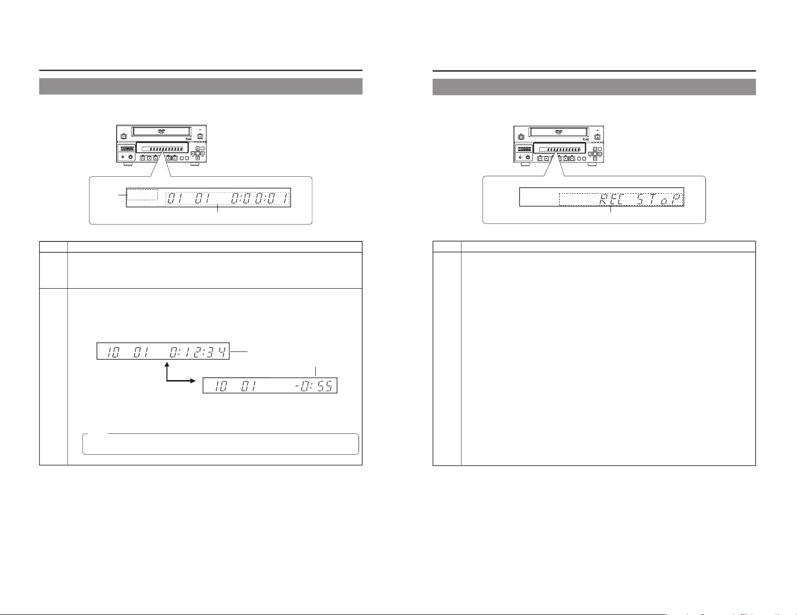
LCD Display and On-Screen Content
LCD Display
The following information and data is presented on the DVD recorder’s LCD display.
TITLE
DOLBYDIGITAL
LPCM
CHAP
OPERATE
PHONES REV
STOP PLAY
DVD RECORDER
BD-X200
FWD PAUSE REC
BUSY
OPEN/CLOSE
TOP
MENU MENU
OPTION DV Y/C LINE
SET UP
AUDIO
CH1
CH2
TITLE
DOLBY DIGITAL
LPCMMPEG
CHAPTER
SET
No. Description
1
Encoding format for audio recordings (LPCM, DOLBY DIGITAL)
Recording mode : The encoding format set using AUDIO ENCODE from the RECORDER MENU (1/2) screen is
displayed.
Playback mode : The encoding format used for audio on the current disc is displayed.
2
Information relevant to the current mode.
䡵Title number / Chapter number / Counter
● When in Recording mode, the LCD display indicates the title number and chapter number currently being recorded,
in addition to either the elapsed title-recording time or the remaining disc space.
The SET button can be pressed to toggle between display of the elapsed recording time and the remaining disc
space in the counter area.
TITLE
CHAP
TITLE
CHAP
● When in Playback mode, the LCD display presents the title number and chapter number currently being played,
in addition to either the elapsed title-playback time or the remaining title-playback time.
The SET button can be pressed to toggle between display of elapsed and remaining title-playback time in the
counter area.
2
1
Elapsed title-recording time (Hour:Minute:Second)
Remaining disc space
(Hour:Minute)
SET button
Note
The remaining disc and title time depend on the amount of data comprising video, and for this reason, they
should be taken as being a general indication and not an exact figure.
15
TITLE
DOLBYDIGITAL
LPCM
CHAP
OPERATE
PHONES REV
STOP PLAY
DVD RECORDER
BD-X200
FWD PAUSE REC
BUSY
OPEN/CLOSE
TOP
MENU MENU
OPTION DV Y/C LINE
SET UP
AUDIO
CH1
CH2
TITLE
DOLBY DIGITAL
LPCMMPEG
CHAPTER
SET
No. Description
2
䡵Indication of the current operating mode
PLEASE WAIT : The DVD recorder is starting up.
OPERATE OFF : The DVD recorder is preparing to shut down.
NO DISC : The DVD recorder currently contains no disc.
LOADING : A disc is being loaded into the DVD recorder.
DVD-R : The current disc is a non-finalized DVD-R. (Approximately 3 seconds)
DVD-RW : The current disc is a non-finalized DVD-RW. (Approximately 3 seconds)
DVD:The current disc is a finalized DVD-R or DVD-RW. (Approximately 3 seconds)
REC PAUSE : The DVD recorder is switching from Recording mode to Recording Pause mode.
REC STOP : The DVD recorder is switching from Recording mode to Stop mode.
MENU EDIT : A title menu or chapter menu is currently being edited.
EJECT : The current disc is being ejected.
TITLE CLOSE : The DVD recorder is performing title-close processing.
FINALIZE : The DVD recorder is finalizing the disc.
ERASE : The DVD recorder is erasing data from a DVD-RW disc.
TOP MENU : The disc’s top menu is being played.
MENU : A menu is being played.
ENCODING XX : Encoded video is being output. (XX indicates the bit rate.)
䡵Display of the Setup Menu
Menu items and setting values from the Setup Menu are displayed. (☞ Page 74)
䡵Event messages
Messages relating to incorrect operation and the like are displayed for approximately 3 seconds. (
☞ Page 19)
䡵Alarm messages
Alarms are displayed when the DVD recorder cannot obey a command. (☞ Page 20)
2
Page 11
16
LCD Display and On-Screen Content
On-Screen Content
In addition to E-E and playback screens, the monitor connected to the DVD recorder’s VIDEO LINE OUT terminal can display the
following.
● Status messages
● Event messages
● Alarm messages
● The Setup Menu (☞ Page 74)
● Recording-operation control screens: REC CONTROL panel (☞ Page 41)
REMOTE CONTROL screen ( ☞
Page 60)
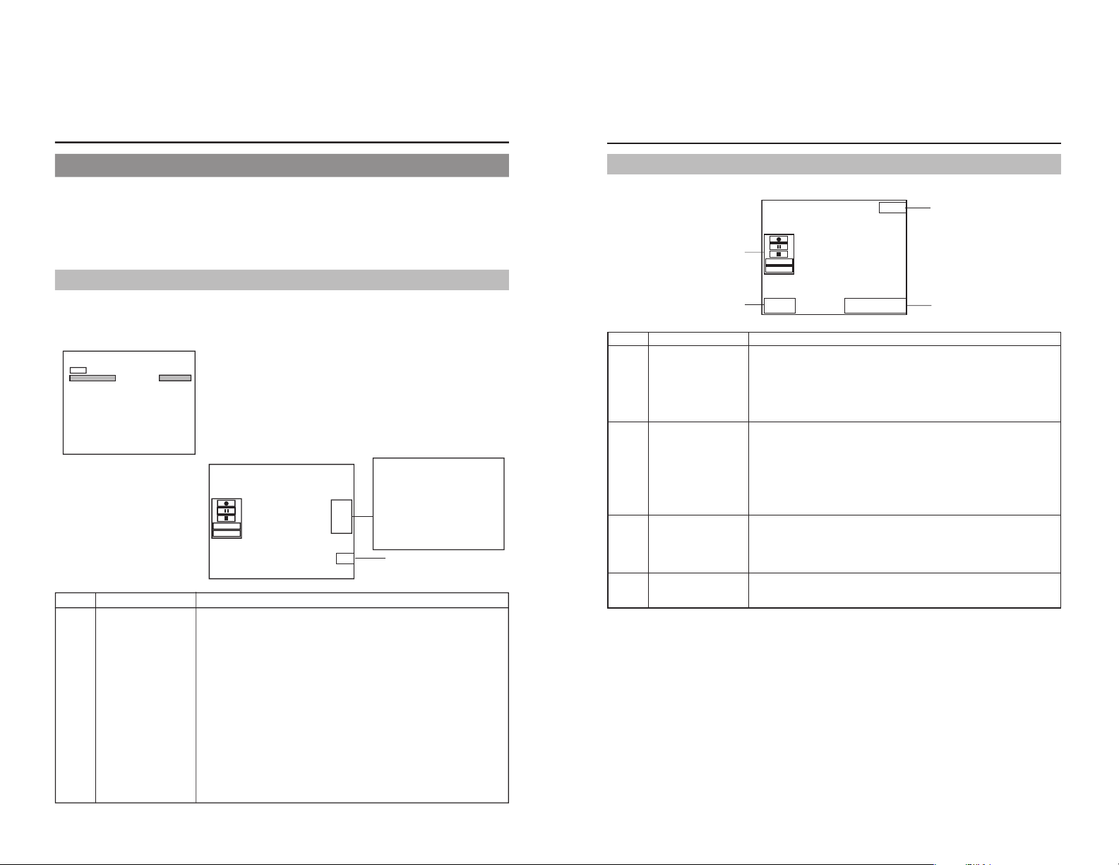
Status Messages
The DVD recorder’s setting condition and operation status are indicated by status messages, and these messages are displaye d
on E-E or playback screens.
The DISPLAY MENU screen can be used to indicate whether or not status messages are to be displ
ayed.
000 min
04/05/04
11:20:00
TITLE 1 0:11:22
CHAPTER
1 0:11:22
REC
FINALIZE
DISC
TITLE
DISPLAY MENU screen
䡵 To display status messages:
Set DISPLAY from the DISPLAY MENU screen to ON.
䡵 The various items of status information for display can be selected.
䡵 If DISPLAY is set to OFF, no status information will be displayed.
Status Messages
1
Data relevant to recording:
If the SET UP button is pressed
while in Recording mod
e, the
video bit-rate setting and the audio
encoding format will be displ
ayed.
If the SET UP button is then
pressed once again, this
information is removed from the
screen.
No. Item Description
1
Operation Mode This area indicates the DVD recorder’s current mode of ope
ration.
Use RECORDER MODE from the DISPLAY MENU screen to indicate whether or not
this is to be displayed.
NO DISC : The DVD recorder currently contains no disc.
EJECT : The current disc is being ejected.
OPE OFF : Operate Off mode
STOP : Stop mode
REC : Recording mode
REC PAUSE : Recording Pause mode
PLAY : Playback mode
STL : Still mode
FWD × 3 : Fast-forward play at 3 times normal speed
FWD × 15 : Fast-forward play at 15 times normal speed
REV × 3 : Fast-reverse play at 3 times normal speed
REV × 15 : Fast-reverse play at 15 times no
rmal speed
SLOW FWD 0.50 : Slow-forward play at 0.5 times normal speed
SLOW FWD 0.06 : Slow-forward play at 0.06 times normal speed
SLOW REV 0.50 : Slow-reverse play at 0.5 times normal speed
SLOW REV 0.06 : Slow-reverse play at 0.06 times normal speed
LOADING : A disc is being loaded.
MENU
DISPLAY
ON
TITLE/CHAPTER
ON
RECORDER MODE
TIME+DATE
ON
TIME/DATE
REMAIN
ON
DATE STYLE
MM/DD/YY
(DD/MM/YY:
E-model)
DISPLAY MENU
17
Status Messages (continued)
000 min
04/05/04
11:20:00
TITLE 1 0:11:22
CHAPTER
1 0:11:22
REC
FINALIZE
DISC
TITLE
4
3
2
5
Status Messages
Title number / Chapter
number / Counter
Date / Time
Remaining time
REC CONTROL panel
No. Item Description
2
3
4
5
Use TITLE/CHAPTER from the DISPLAY MENU screen to indicate whether or not this
is to be displayed.
Recording mode : The title number and chapter number currently being recorded are
displayed together with the elapsed title-recording time (in hours,
minutes, and seconds).
Playback mode : The title number and chapter number currently being played are
displayed together with the elapsed title-playback time (in hours,
minutes, and seconds).
Use TIME/DATE from the DISPLAY MENU screen to select the way in which the date
and time are displayed.
OFF : No information is displayed.
DATE : Only the date is displayed.
TIME : Only the time is displayed.
TIME+DATE : Both date and time are displayed.
● The date display style can be changed using DATE STYLE from the DISPLAY MENU
screen.
Recording mode : The date and time from the inter nal clock are displayed.
Playback mode : The date and time of disc finalizing are displayed.
Use REMAIN from the DISPLAY MENU screen to indicate whether or not this is to be
displayed.
Recording mode : The amount of video that can still be recorded on the current disc is
displayed (in minutes).
Playback mode : Not displayed
* Remaining time is to be used as a general guide, not as an exact figure.
Provided that a recordable disc has been inserted, this panel will be displayed whenever
REC CONTROL from the REMOTE MENU screen is set to ON.
The REC CONTROL panel can be used to control recording operations. (☞ Page 41)
Page 12
18
LCD Display and On-Screen Content
On-Screen Content (continued)
Disc Status
When a disc is inserted into the DVD recorder, one of the following disc status messages is displayed on the monitor screen.
090 min
04/05/04
11:20:00
TITLE 1 0:00:00
CHAPTER
1 0:00:00
REC
DVD-RW
*: The disc status is not displayed if DISPLAY from the DISPLAY MENU screen is set to OFF.
Status Description
DVD-R The current disc is a non-finalized DVD-R. (Approximately 3 seconds)
D
VD-RW
The current disc is a non-finalized DVD-RW. (Approximately 3 seconds)
DVD The current disc is a finalized DVD-R or DVD-RW. (Approximately 3 seconds)
INVALID DISC The current disc is neither a DVD-R nor DVD-RW.
Disc status
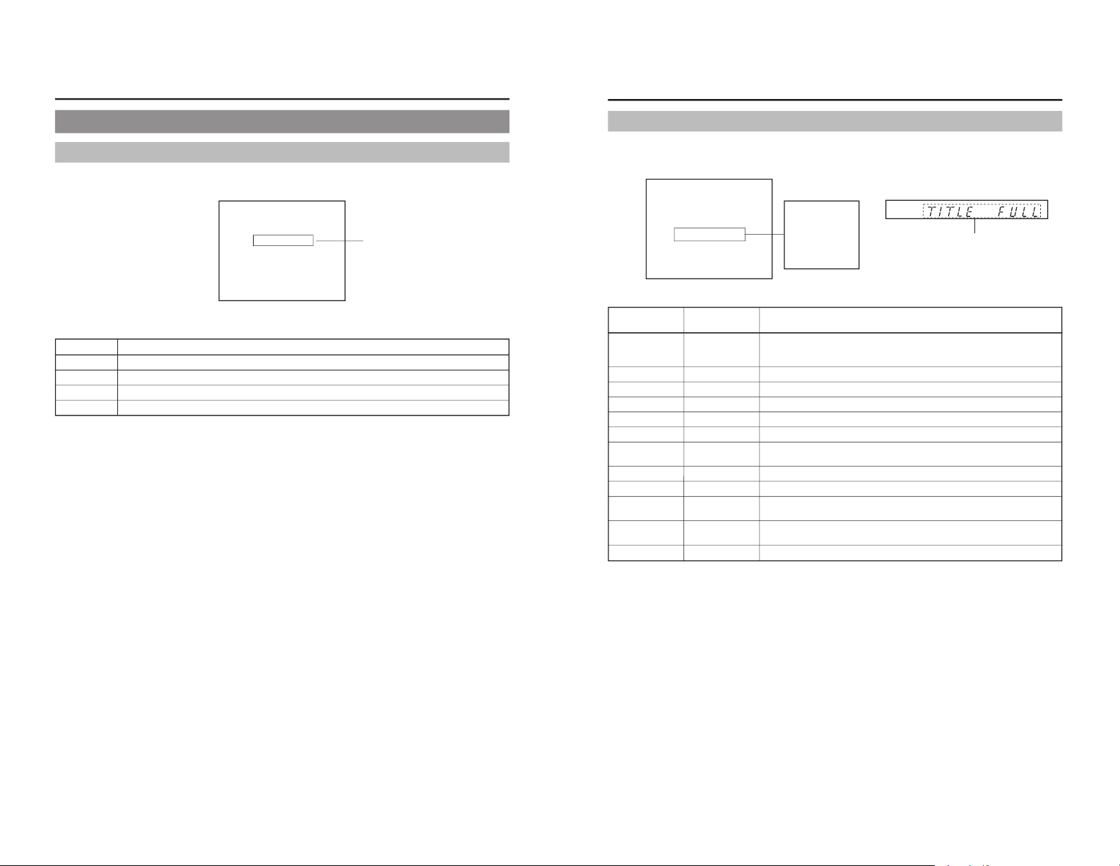
19
Event Messages
Event messages are displayed on the DVD recorder’s LCD display and on the monitor when incorrect operations are attempted.
These messages will remain on-screen for approximately 3 seconds.
000 min
04/05/04
11:20:00
TITLE 1 0:11:22
CHAPTER
1 0:11:22
REC
TITLE FULL
DOLBYDIGITAL
LPCM
LCD display
Monitor message
message
Description
INVALID TV INVALID TV A signal of an invalid for mat has been input.
Alternatively, an attempt has been made to play a disc containing signals of an invalid
format.
TITLE FULL TITLE FULL Recording was attempted on a disc already containing 99 titles.
CHAPTER FULL CHAP FULL An attempt was made to add a chapter to a title already containing 99 chapters.
NOT FINALIZE NOT FINAL An attempt was made to eject a disc before it was finalized.
———— A L-xxxx-R Set value is displayed when changing the recording level of analog audio.
———— D L-xxxx-R Set value is displayed when changing the recording level of digital audio.
DURATION OVER ———— Auto Edit was carried out when the remaining disc space became insufficient during
RS-422A or DV remote operation.
INVALID EDL ———— An incorrect value was entered during the registration of an edit list (EDL).
EDL UNDER EDIT ———— EDL Load was carried out after starting the registration of an edit list (EDL).
NO CASSETTE ———— During RS-422A or DV remote operation, an attempt was made to control the
connected VCR while it did not contain a video tape.
NOT CONNECT ———— During RS-422A or DV remote operation, a control operation was attempted while
no external device was connected.
EDIT FAILURE ———— Editing could not be completed normally.
LCD display
Monitor screen
Event messages:
Displayed when
DISPLAY from
the DISPLAY
MENU screen is
set to ON.
Event message
Page 13
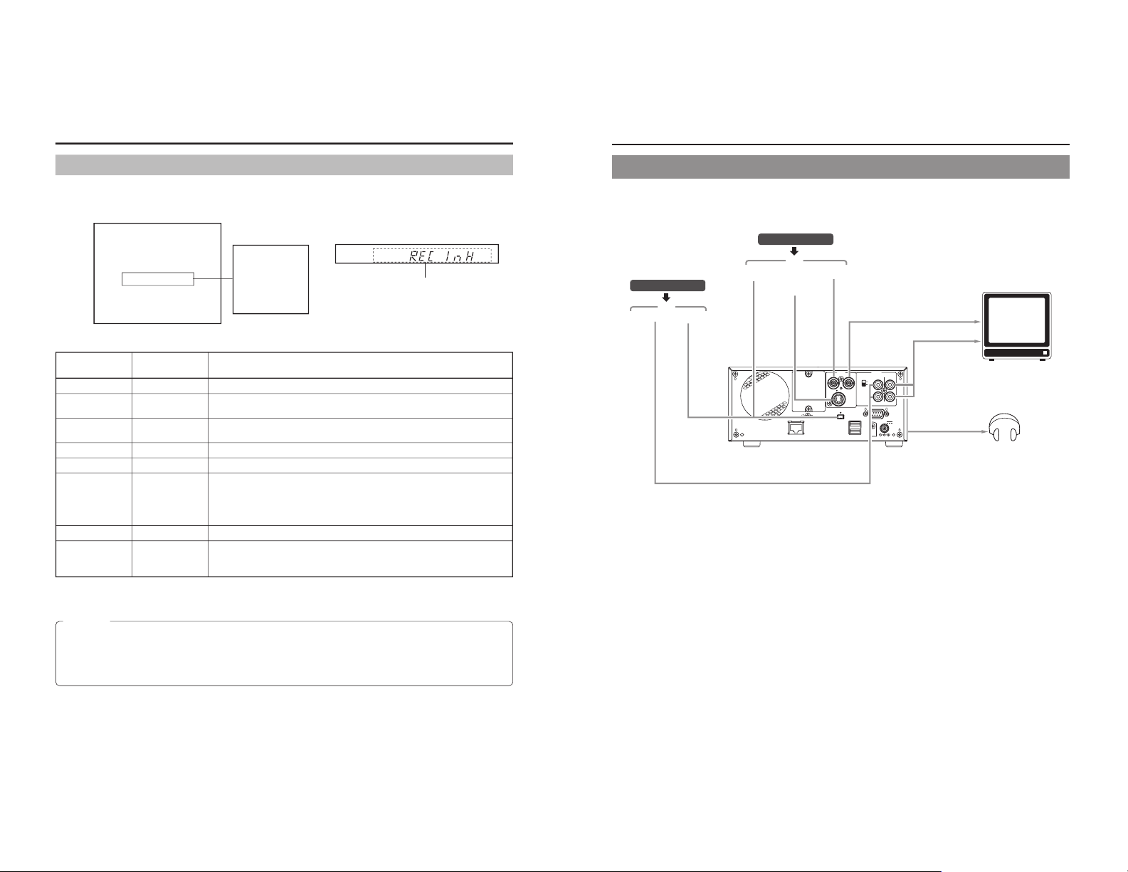
20
LCD Display and On-Screen Content
Alarm Messages
Alarm messages are displayed on the DVD recorder’s LCD display and on the monitor when the recorder cannot obey a command.
These messages will remain on-screen until the next operation is carried out.
000 min
04/05/04
11:20:00
TITLE 1 0:11:22
CHAPTER
1 0:11:22
REC
REC INHIBIT
DOLBYDIGITAL
LPCM
LCD display
Monitor message
message
Description
INVALID DISC INVALID DISC The current disc is not a DVD-R or DVD-RW.
NOT X200 NOT X200 A disc recorded using a different DVD recorder was inserted or played.
REC INHIBIT REC INH ● Recording was attempted using a disc on which no more data can be recorded.
● The current disc is a non-finalized DVD-RW to which no more data can be recorded.
COPY INHIBIT COPY INH Recording of a copy-protected signal was attempted.
DISC FULL DISC FULL All remaining space on the disc is used up during recording.
CELL OVER CELL OVER The number of cells for a single title exceeded 255.
This will be displayed when the recording time for a single title is exceeded as a
result of setting ENCODE QUALITY to a low value (i.e., 4 Mbps or lower), recording
content with little movement, or other similar factors. No error will be triggered when
the time is within that set for the total content.
REGION CODE REGION CODE An attempt was made to play a disc for which a region code has been set.
OVERHEATING! OVERHEATING Displayed when the internal temperature of the set rises due to fan malfunction, etc.
In this case, immediately turn off the power and discontinue use. The power will
automatically shut down in about 20 minutes after the OVERHEATING display.
LCD display
Monitor screen
Alarm messages:
Displayed when
DISPLAY from the
DISPLAY MENU
screen is set to
ON.
Alarm message
CAUTION
If alarm messages such as
“INVALID DISC” are displayed several times when a disc recorded using the BD-X200 or a blank
disk is inserted, there is a possibility that the disc itself has been damaged. In such a case, the damaged disc should be
replaced with a new one.
If the alarm messages continue to appear after replacing the disc, the problem may lie within the DVD recorder, and in such a
case, you are recommended to contact either the store where this BD-X200 was purchased or your nearest JVC authorized
dealer.
21
Preparation
Signal Connections
䡵 Audio and video signals
同期信号発生器
DV IN/OUT
DV IN/OUT Y/C IN LINE IN
LINE OUT
AUDIO OUT
AUDIO IN
DV
DV
VIDEO AUDIO
ININOUT
IN
OUT
CH1
CH2
REMOTE
USB
DV IN/OUT
SIGNAL
LAN
GND
DC 19V
4dB
8dB
INPUT
LEVEL
LINE
Y/C
Note 1: The video signal for input is selected using INPUT SELECT from the INPUT SELECT MENU screen.
Note 2: The audio signals for input are selected using INPUT SELECT from the INPUT SELECT MENU screen.
When either LINE or Y/C is set for INPUT SELECT, the analog audio signals from the AUDIO IN terminals will be selected
for input.
When DV is set for INPUT SELECT, the DV audio signals from the DV IN/OUT terminal will be selected for input.
Note 3: When the DVD recorder is in Stop or Recording mode, the video input signal is output on the E-E screen as a composite
video signal.
In addition, the Setup Menu and other setting screens are also displayed on the monitor connected to this terminal. The
DVD recorder’s operation status and other relevant information are displayed on-screen when DISPLAY from the DISPLAY
MENU screen has been set to ON.
Note 4: The Y/C IN terminal’s specification (i.e., S1 or S2) can be selected using Y/C TERMINAL MODE from the RECORDER
MENU (2/2) screen.
Note 5: The standard input level for audio signals input via the AUDIO IN terminals (i.e., +4 dB or –8 dB) can be selected using the
AUDIO INPUT LEVEL switch on the rear panel.
Input
Input
Audio outputs for VCR
Analog audio
YC separate
Composite
Note 1
Note 2
Note 4
Note 3
Composite
Analog audio
PHONES
(on front panel)
Stereo
Headphones
Monitor or TV
Video outputs for VCR
Note 5
Page 14
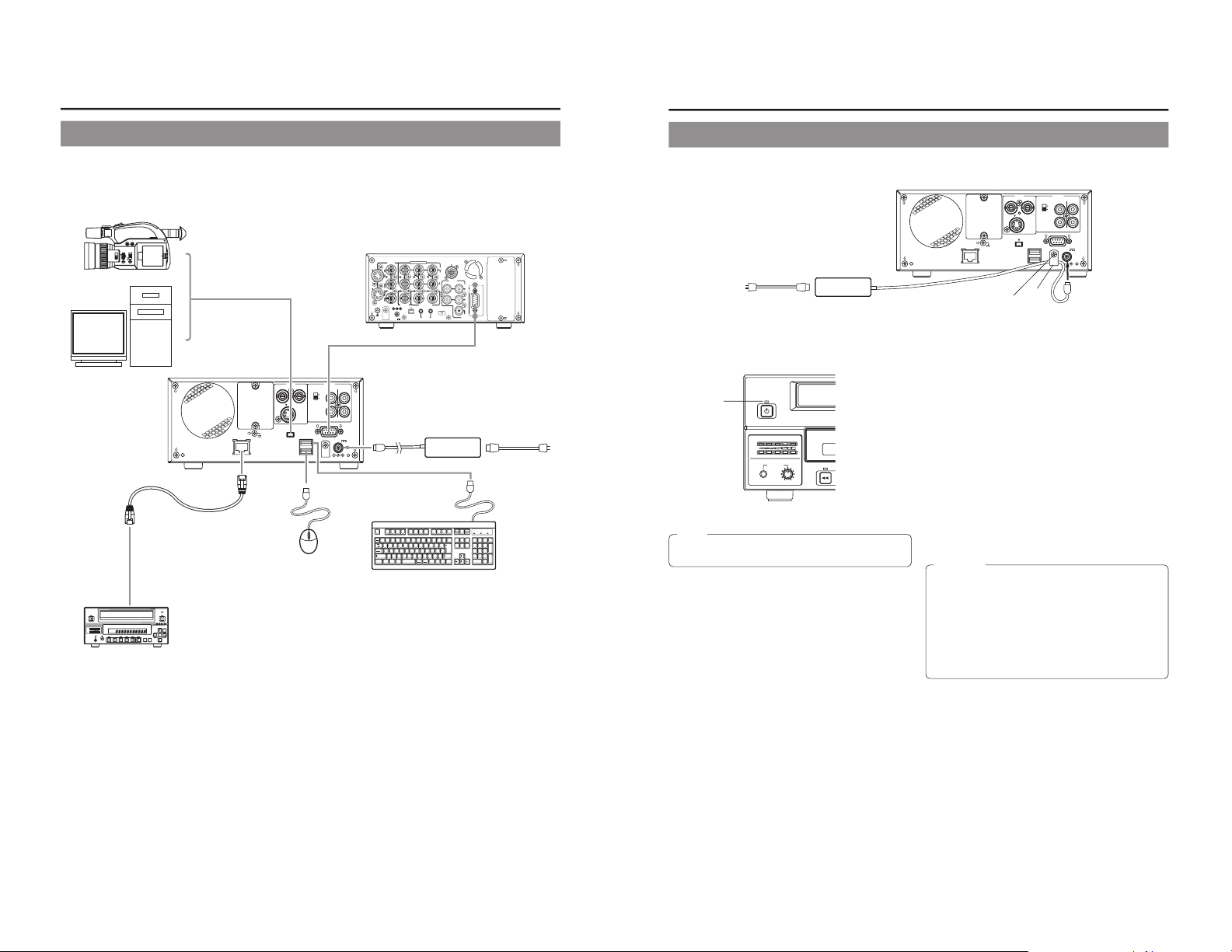
22
Signal Connections (continued)
䡵 Control signals
VIDEO AUDIO
ININOUT
IN
OUT
CH1
CH2
REMOTE
USB
DV IN/OUT
SIGNAL
LAN
GND
DC 19V
4dB
8dB
INPUT
LEVEL
LINE
Y/C
OPEN/CLOSE
OPERATE
OPTION
DV LINEY/C
BUSY
SET UP
SET
TOP
MENU
RECPAUSE
PLAY FF
STOP
REW
PHONES
AUDIO
CH1
CH2
MENU
DV CAMCORDER GY-DV300
AUDIO
LEVEL
CH-1 CH-2
ND FILTER
ON
OFF
FOCUS
AUTO
PUSH
AUTO
MANU
OPEN
IRIS
VIDEO
LINE
IN
OUT
MONITOR
OUT
DC12V
DV
IN/OUT
IN OUT
OFF
AUDIO
REMOTE2
IN
B-YR-Y
SYNC IN
TIME CODE
IN OUT
Y
COMPONENT
OUT
CH 1/3 CH 2/4
IN
OUT
MONITOR
OUT
REMOTE1
TIMER
REC PLAY
SERIAL
REMOTE
SINGLE
GND
Y/C
Esc F1 F2 F3 F4 F5 F6 F7 F8 F9 F10 F11 F12
Print
Screen
Sysrq
Scroll
Lock
Pause
Break
Tab
Caps Lock
Shift Shift
Ctrl CtrlAlt
Alt
Enter
Back
Space
Insert
Delete End
Home
Page
Up
Page
Down
Enter
0
12
56
+
-
4
897
.
/
*
Num
Lock
1
Q
A
ZXCVBNM
<>
? _
SDFGHJKL
U
WER T Y I O P
234567890
-
^
@
¥
「
「
;
:
、
。
/
・
.
/
,
つ
`
[
]
」
+
*
!#$%& =(
)
'
〜
BD-X200
BD-X200
Note 1: In order to use the RS-422A REMOTE terminal, set REMOTE SELECT from the REMOTE MENU screen to 9PIN(MASTER).
Note 2: In order to carry out control using the DV IN/OUT terminal, make the appropriate selection using REMOTE SELECT from
the REMOTE MENU screen.
Note 3: One of the following DV cables should be used.
VC-VDV204 (2 m, 4P-4P) from JVC
VC-VDV206 (2 m, 4P-6P) from JVC
Note 4: When connecting a secondary device directly to your BD-X200, use a Category 5, cross-wired Ethernet cable.
Preparation
DV
camera or VCR
Nonlinear editing system
DV
Note 3
DV cable
Note 2
DV IN /OUT
Note 1
Remote cable
RS-422A compatible VCR
RS-422 REMOTE
REMOTE
LAN
USB
DC IN
AC adaptor (included)
Po
wer cord (included)
AC
Keyboard
Mouse
Category 5 cable
LAN
Receiver device
Note 4
23
Power Connections
Connect the AC adaptor (included) to the DVD recorder.
VIDEO AUDIO
ININOUT
IN
OUT
CH1
CH2
REMOTE
USB
DV IN/OUT
SIGNAL
LAN
GND
DC 19V
4dB
8dB
INPUT
LEVEL
LINE
Y/C
Clamp
AC adaptor
(included)
Power cord
(included)
DC IN
AC
OPERATE
PHONES REV
AUDIO
CH1
CH2
OPERATE
indicator
1.
Connect the AC adaptor’s DC cord to the DVD
recorder’s DC IN terminal.
2.
Secure the DC cord using the DC power cord
clamp in order to prevent accidental
disconnection.
q Remove the screw and then the clamp.
w Inser t the DC cord into the clamp, and then secure the
clamp to the DVD recorder.
3.
Connect the power cord (included) to the AC
adaptor’s AC IN terminal.
4.
Insert the power cord into an electrical outlet.
● Pow er will be supplied to the DVD recorder and the
OPERATE indicator will be lit up in red. (Operate Off mode)
Note
A small amount of current will be required by the DVD
recorder when in Operate Off mode.
CAUTION
● Always use the AC adaptor provided with the DVD
recorder.
The use of other power sources should be avoided.
● Do not disconnect the DC cord or power cord during
recording or playback.
In the case of DVD-R discs, failure to observe this
precaution will result in the discs becoming unusable.
In the case of DVD-RW discs, it will be necessary to erase
all data from the disc and to start recording again from
the beginning.
Screw
Page 15
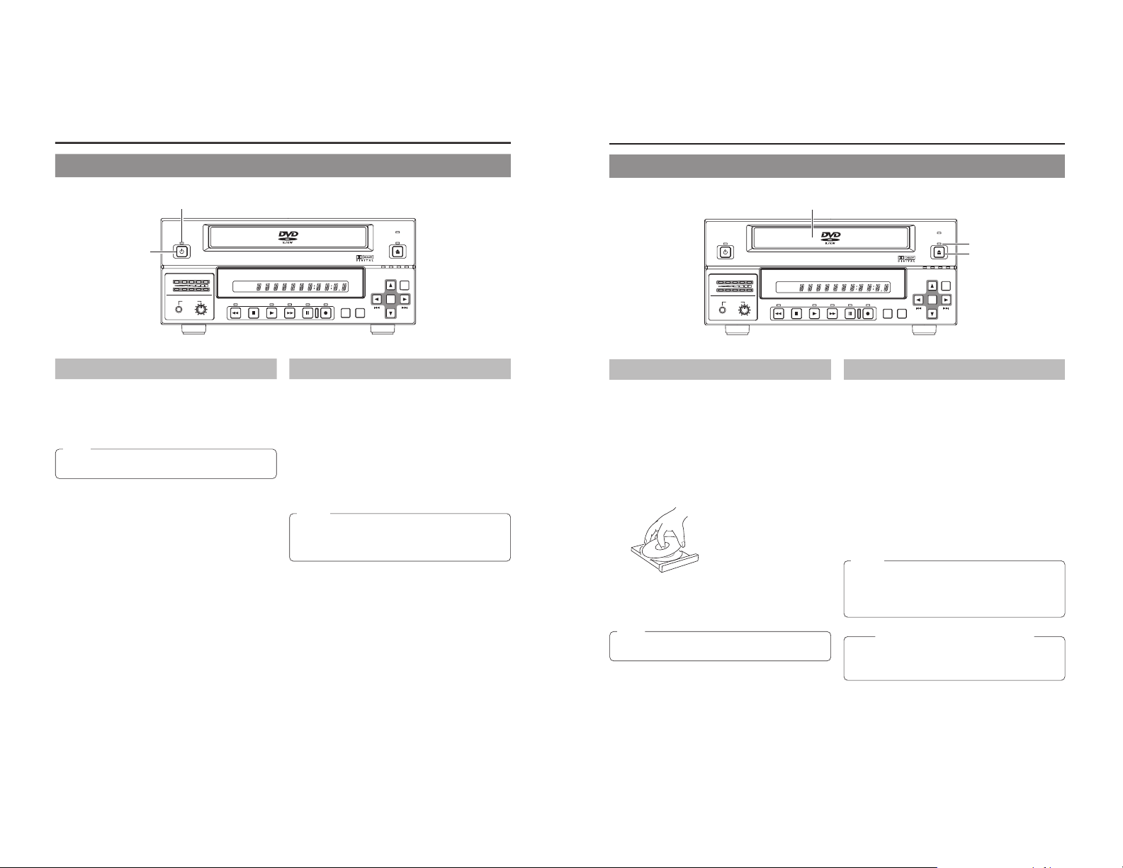
24
Preparation
Turning the Power On & Off
OPERATE
PHONES REV
STOP PLAY
DVD RECORDER
BD-X200
FWD PAUSE REC
BUSY
OPEN/CLOSE
TOP
MENU MENU
OPTION DV Y/C LINE
SET UP
AUDIO
CH1
CH2
TITLE
DOLBY DIGITAL
LPCMMPEG
CHAPTER
SET
OPERATE button
OPERATE indicator
Turning the Power On
䡵 While in Operate Off mode (i.e., the OPERATE indicator
is lit up in red), press the OPERATE button.
●
The power will turn on, the color of the OPERATE indicator
will change to green, and the DVD recorder will become
ready for use. (Operate On mode)
Note
A period of 45 seconds may pass before the DVD recorder
adopts Operate On mode as it prepares for operation.
Turning the Power Off
䡵 Stop the DVD recorder.
(It is recommended that you eject the disc at this time.)
1.
Press the OPERATE button.
● The DVD recorder will adopt Operate Off mode and the
color of the OPERATE indicator will change to red.
2.
If the DVD recorder will not be used for an extended
period of time, disconnect the AC adaptor.
● Before disconnecting the AC adaptor, be sure to remove
the power cord from the electrical outlet.
Notes
● Pressing the OPERATE button will have no effect in
Recording mode or Recording Pause mode.
● Pressing this button also has no effect during finalizing,
erasing, and dubbing.
25
Inserting & Removing Discs
OPERATE
PHONES REV
STOP PLAY
DVDRECORDER
BD-X200
FWD PAUSE REC
BUSY
OPEN/CLOSE
TOP
MENU MENU
OPTION DV Y/C LINE
SET UP
AUDIO
CH1
CH2
TITLE
DOLBY DIGITAL
LPCMMPEG
CHAPTER
SET
Disc tray
Inserting a Disc
䡵
Press the OPERATE button to activate Operate On mode .
1.
Press the OPEN/CLOSE button.
● The disc tray will open automatically.
While the disc tray is open, the OPEN/CLOSE indicator
will be lit up.
2.
Place the disc on the disc tray.
Ensure that the disc is inserted correctly into the tray’s recess
with the printed side facing upward.
● Carefully place the disc in the tray so as not to hit the front
panel.
3.
Press the OPEN/CLOSE button.
● The disc tray will close automatically.
Note
When a disc is inserted, information about that disc is
displayed on-screen. (☞ Page 18)
Removing a Disc
䡵 Stop the DVD recorder.
1.
Press the OPEN/CLOSE button.
● The disc tray will open automatically.
While the disc tray is open, the OPEN/CLOSE indicator
will be lit up.
● If the current disc has not been finalized, the message
“NOT FINALIZE” will appear on both the monitor and LCD
display.
2.
Remove the disc from the disc tray.
Be sure to wait until the disc tray has opened fully before
removing the disc.
3.
Press the OPEN/CLOSE button.
● The disc tray will close automatically.
Precautions regarding the disc tray
●
Do not push the disc tray as it is opening or closing.
● Do not place objects other than discs on the disc tray.
● Do not press down on the disc tray.
OPEN/CLOSE indicator
OPEN/CLOSE button
Notes
● If the DVD recorder is in either Recording mode or
Recording Pause mode, the disc tray will not open when
the OPEN/CLOSE button is pressed.
● Pressing this button also has no effect during finalizing,
erasing, and dubbing.
Page 16

26
Preparation
Using a Keyboard & Mouse
Menu settings, the title and chapter settings, and other DVD recorder settings are carried out from setting screens displayed on the
TV or monitor. In addition, recording operations can also be carr ied out from similar screens.
Although the DVD recorder’s b
uttons are used in setting and operation screens, a keyboard and mouse can be used as an alternative.
䡵 Connections
Connect a USB keyboard and mouse to the two USB
terminals on the back of the DVD recorder.
Recommended manufacturers: Logitech
Esc F1 F2 F3 F4 F5 F6 F7 F8 F9 F10 F11 F12
Print
Screen
Sysrq
Scroll
Lock
Pause
Break
Tab
Caps Lock
Shift Shift
Ctrl CtrlAlt
Alt
Enter
Back
Space
Insert
Delete End
Home
Page
Up
Page
Down
Enter
0
12
56
+
-
4
897
.
/
*
Num
Lock
1
Q
A
ZXCVBNM
<>
? _
SDFGHJKL
U
WER T Y I O P
234567890
-
^
@
¥
「
「
;
:
、
。
/
・
.
/
,
`
[
]
」
+
*
!#$%& =(
)
'
〜
VIDEO AUDIO
ININOUT
IN
OUT
CH1
CH2
REMOTE
USB
DV IN/OUT
SIGNAL
LAN
GND
DC 19V
4dB
8dB
INPUT
LEVEL
LINE
Y/C
䡵 Procedure
The following functions can be controlled using the keyboard and mouse.
USB terminals
The entry of names and comments for the title and chapter menus is carried out using the keyboard. (Set KEYBOARD STYLE from
the SYSTEM MENU screen in accordance with the keyboard’s input language.)
Note
Unless otherwise specified, this user’s manual
describes procedures carried out from the DVD
recorder itself.
Function Front panel Keyboard Mouse
Selection of menu t button † key Move the mouse.
items or setting 8 button © key And then left
values 6
button
∞ key click.
7 button √ key
Confirmation of
SET button Enter key Left click.
settings
27
Setting & Displaying the Date & Time
Use the following procedure to set the internal clock
’s date and time. Even when the DVD recorder’s power is turned off, the clock’s
date and time settings are stored using the internal battery.
Note that these settings are used to write the current date and time to a disc being finalized.
The DISPLAY screen can be used to indicate whether or not the date and time are to be displayed on-screen.
OPERATE
PHONES REV
STOP PLAY
DVDRECORDER
BD-X200
FWD PAUSE REC
BUSY
OPEN/CLOSE
TOP
MENU MENU
OPTION DV Y/C LINE
SET UP
AUDIO
CH1
CH2
TITLE
DOLBY DIGITAL
LPCMMPEG
CHAPTER
SET
6 button
SET UP button
t button
SET button
7 button8 button
Setting the Date and Time
Setting of the date and time is carried out using the CLOCK ADJUST MENU
screen. During this procedure, the monitor connected to the VIDEO LINE OUT
terminal is used to monitor the setting of data.
䡵 Turn on the power and ensure that the DVD recorder is stopped.
1.
Press the SET UP button to display the Setup Menu.
2.
Open the CLOCK ADJUST MENU screen.
q Use the 6 and
7 buttons to select CLOCK ADJUST. (The currently
selected menu item is displayed as highlighted.)
w Press the SET button to open the CLOCK ADJUST MENU screen.
3.
Set the date and time as required.
q Use the 6 and 7
buttons to select either DATE or TIME. Then press the
SET button.
w Use the
t and 8 buttons to select the digit to be changed. (The currently
selected digit is displayed as highlighted text.)
e Use the
6 and 7 buttons to change the value of the selected digit.
r Repeat steps w through
e to make all of the required settings, and then
press the SET button.
4.
After completing all of the required settings, return to the Setup
Menu.
To do this, use the 6 or 7 buttons to select MENU and then press the SET
button.
5.
Return to the normal screen display.
●
To do this, press the SET UP button
or
● Select EXIT from the Setup Menu and press the SET button.
EXIT
DISC MENU
INPUT SELECT
SYSTEM
PRESET STYLE
RECORDER
REMOTE
DISPLAY
CLOCK ADJUST
DUBBING
NETWORK
MENU
DATE
04/05/04
10:00
TIME
CLOCK ADJUST MENU
MENU
DATE
04/05/04
12:00
TIME
CLOCK ADJUST MENU
Setup Menu
CLOCK ADJUST MENU screen
Note
It is not possible to set the time in units of seconds. After setting the
minutes, press the SET button in sync with a time signal.
CLOCK SETTING
07 44
07 :
44
SET
Page 17

28
Setting & Displaying the Date & Time (continued)
Displaying the Date and Time
Use the DISPLAY MENU screen to indicate whether or not the date and time are
to be displayed on-screen and to set a display style. (墌 Page 74 for details
regarding setting methods.)
DISPLAY MENU Screen Makeup
䡵 DISPLAY: This parameter is used to indicate whether or not data is to
be displayed on-screen.
ON : Data will be displayed on-screen. The following parameters can be
used to indicate which data is to be displayed.
OFF : No data is displayed on-screen.
䡵 TIME/DATE: This parameter is used to set the way in which the date
and time are displayed.
OFF : Neither date or time are displayed.
TIME : Only the time is displayed.
DA
TE : Only the date is displayed.
TIME + DATE : Both date or time are displayed.
䡵
DATE STYLE: This parameter is used to select the way in which the
date is to be displayed.
YY/MM/DD : Year, month, day
MM/DD/YY : Month, day, year
DD/MM/YY : Day, month, year
DISPLAY MENU screen
Preparation
To display date and time information on-screen;
●
Set DISPLAY to ON.
● Set TIME/DATE to anything other than OFF.
Date and time information is displayed as follows.
Mode Displayed information
Recording or Stop The value of the internal clock
Playback The date and time at which the current disc was
finalized.
MENU
DISPLAY
ON
TITLE/CHAPTER
ON
RECORDER MODE
TIME+DATE
ON
TIME/DATE
REMAIN
ON
DATE STYLE
MM/DD/YY
DISPLAY MENU
000 min
04/05/04
11:20:00
TITLE 1 0:11:22
CHAPTER
1 0:11:22
REC
On-screen display
TIME/DATE
(DD/MM/YY:
E-model)
29
Settings & Controls for Recording
DVD Recording
DVD recording is carried out using the following procedure.
Pre-Recording Settings
Preparation of the DVD-R or DVDRW (video mode only).
On-screen settings
Adjustment of audio recording levels.
Selection of styles for the title and
chapter menus
● Insert a new DVD-R or DVD-RW (video mode), or alternatively, a similar disc that has
been recorded on using the DVD recorder.
● If the recording on a DVD-RW is to be performed once again from the beginning, erase
the disc’s data using ERASE from the DISC MENU screen. (☞ Page 30)
Use the setting screens to select the appropriate recording signal, setup the recording
conditions, and make other necessary settings. (☞ Page 31)
Audio recording levels can be adjusted in one of two different ways. (☞ Page 35)
The title and chapter menus are used during playback of a disc to select the section of
the disc to be viewed. A total of five different display styles have been made available for
these menus, and these can be selected using the PRESET STYLE MENU screen. In
addition, the DVD recorder also allows you to freely modify these display styles.
(☞ Page 37)
Recording Operations
(☞ P
age 38)
● The section between the start of recording using the REC and PLAY buttons
and the end of recording using the STOP button constitutes a single recording
title, and each title is assigned a unique number.
A single disc can contain up to 99 different titles.
●
Each title can be separated into a number of different chapters by inserting
chapter marks at the appropriate points. Unique numbers are also assigned
to chapters, and a single title can contain up to 99 different chapters.
● Adding chapters
A chapter mark is inserted automatically whenever recording is paused.
In addition, CHAPTER CREATION from the RECORDER MENU (1/2) screen
can also be used to setup the automatic or manual insertion of chapter marks.
● Thumbnails (i.e., the frame at the start of recording) and backgrounds are
automatically created for the title and chapter menus using the style selected
using PRESET STYLE.
If EDIT MENU from the SYSTEM MENU screen is set to ENABLE before the
start of recording, it will be possible to modify the chapter menu’s style and
thumbnails and to insert chapter names and comments whenever recording
is stopped (i.e., whenever title closing is performed).
● Once title closing has been carried out, it will not be possible to modify the
chapter menu.
● The REC CONTROL panel can be used to perform recording operations with
a keyboard and mouse. (REC CONTROL from the REMOTE MENU screen
must be set to ON.)
● If EDIT MENU from the SYSTEM MENU screen is set to ENABLE, it will be
possible to modify the title menu’s style and to input title names when the disc
is being finalized.
Title 1
Chapter 1
Chapter 2
Chapter 3
Chapter 4
Title 2
Chapter 1
Chapter 2
Title 3
(chapter mark)
Start of
recording
End of
recording
(Title closing)
Start of
recording
End of
recording
Start of
recording
End of
recording
(Title closing)
(Title closing)
Processing After Recording
(
☞ Page 42)
If additional recording is to be
performed:
Press the OPEN/CLOSE button and
remove the disc.
If the disc is to be played on this DVD recorder or on a different DVD player:
Finalize the disc.
To do this, select FINALIZE from the DISC MENU screen.
*
When a disc has been finalized, it will not be possible to record more content to it or to
modify its menu styles.
Page 18

30
Settings & Controls for Recording
Preparing a Disc for Recording
䡵
This DVD recorder is capable of recording to DVD-R and DVD-RW (in video mode).
DVD-R : Only discs that conform with DVD-R Standard 2.0 (video mode) can be used.
DVD-RW
: Discs of Version 1.1 or later can be used.
Although Version 1.1 of DVD-RW standards allows the selection of video mode and VR mode for recording, this
DVD recorder performs recording in video mode only.
*Version 1.0 of the DVD-RW standards does not suppor t video-mode recording, and for this reason, the corresponding
discs cannot be used.
䡵In terms of recording characteristics, DVD-R and DVD-RW (video mode) differ as follows.
DVD-R : Each disc can be recorded only once. Erasing of data and re-recording are not possible.
DVD-RW (video mode) : After viewing a disc, all data can be erased and it can be used to record new content.
The condition of the disc being used will dictate the available recording options as follows.
Disc condition Recording operations
DVD-R New content can be recorded. A new title is created and recording
starts from that title’s first chapter.
A new title is created in the unused section of the disc, and recording
starts from that title’s first chapter.
DVD-RW New content can be recorded. A new title is created and recording
starts from that title’s first chapter.
A new title is created in the unused section of the disc, and recording
starts from that title’s first chapter.
Erase the recorded data (as described below), and then record
new content.
Blank disc
A disc recorded on using this DVD recorder
but not yet finalized.
Blank disc
A disc recorded on using this DVD recorder
but not yet finalized.
A recorded disc from which data is to be
erased.
Notes
● If data has been erased from a disc using a different DVD recorder, it may not be possible to record new content to it using
this recorder. To avoid this type of situation, ensure that this DVD recorder is used to erase recorded data.
● New content cannot be recorded to discs that have been finalized.
● Regardless of whether or not finalization has been carried out, it will not be possible to use this DVD recorder to record new
content to a DVD-R or DVD-RW that has been recorded on using other devices.
Erasing All Data From a Disc
1.
Insert the DVD-RW from which data is to be erased.
2.
Press the SET UP button to display the Setup Menu.
3.
Use the 7 and 6 buttons to select DISC MENU and then press
the SET button.
● The DISC MENU screen will appear.
4.
Use the 7
and 6 buttons to select DISC ERASE and then press
the SET button.
● A list of setting values will appear.
5.
Use the 7 and 6 buttons to select EXECUTE from the list and
then press the SET button.
● The erasing of data will begin.
The message “DISC ERASE” appears and the state of progress is displayed
using a progress bar.
● When all data has been erased, the progress bar will disappear.
MENU
FINALIZE
CANCEL
EXECUTE
DISC ERASE
DISC MENU
DISC ERASE
DISC MENU screen
CAUTION
● All of the data recorded to the disc will be erased in this process. Before
starting, therefore, confirm that no important data is stored on this disc.
● Under no circumstances should the power be turned off or the power cord
disconnected while data is being erased.
31
Pre-Recording Settings
䡵 Recorder switch settings
Use the AUDIO INPUT LEVEL switch on the DVD recorder’s
rear panel to select the reference input level for analog audio
(i.e., +4 dB or –8 dB).
䡵
The following screens are used to make settings relevant to
recording.
(Screen setting methods: ☞
Page 75)
● INPUT SELECT MENU screen
This screen is used to select the audio and video signals to
be used.
For more details, refer to page 32.
● SYSTEM MENU screen
• SET UP (U-model only)
This parameter is set when an analog video signal (i.e.,
composite or YC separate) is being input to the DVD recorder.
Specifically, a setting is made to reflect whether or not the
input signal is a setup signal. SETUP should be set to ON if
it is a setup signal, or to OFF if it is not.
• TEST SIGNAL
Set this parameter to ON when the color bar output by the
DVD recorder’s internal signal generator is to be recorded.
• EDIT MENU
This parameter indicates whether or not a screen for menu
editing is to be displayed during title closing and finalizing.
ENABLE : The menu editing screen is to be displayed.
During title closing, this screen can be used to
modify the chapter menu’s
style and thumbnails
and also to insert chapter names. (
☞ Page 47)
During finalizing, the menu editing screen allows
the title menu’s display style to be modified. (☞
Page 53)
DISABLE : The menu editing screen is not to be displayed.
In this case, the chapter menu is created using
preset values as part of title closing when
recording is ended.
● PRESET STYLE MENU screen
This screen is used to select the arrangement and background
style for thumbnails displayed on the tops menu. This DVD
recorder can store eight individual style type (i.e., TYPE1
through TYPE8), and the most suitable type should be selected
here.
For more details, refer to page 37.
● RECORDER MENU screen
The RECORDER MENU screen contains two different pages
of parameters.
RECORDER MENU (1/2) screen
•
CHAPTER CREATION
This parameter indicates whether chapters are to be created
automatically or manually.
MANUAL : Chapters will be created manually. To create a
chapter, press the REC button while recording.
AUTO : Chapters are to be created automatically. In this
case, the DVD recorder will create chapters at
the time intervals set using SET INTERVAL.
•TOTAL CONTENT TIME
This parameter is used to make a setting relevant to the
encoding (or compression) of video data.
A setting should be made here when the DVD recorder is to
automatically set the bit rate based on the recording time
and the remaining disc capacity. Specifically, this parameter
sets the recording time.
• ENCODE QUALITY
This parameter is used to manually set the bit rate for video
data.
• AUDIO ENCODE
This parameter is used to set the format for encoding (or
compressing) audio data.
For more details regarding the encoding of audio and video,
refer to pages 33, 34.
• ASPECT
This parameter is used to set the aspect for recorded video.
(AUTO, 4:3, LETTER BOX, or SQUEEZE)
RECORDER MENU (2/2) screen
• Y/C TERMINAL MODE
This parameter indicates whether the Y/C IN terminal’s
specification is S1 or S2. (Specifically, it selects the recording
method for the wide-screen discrimination signal.)
• THUMBNAIL FORM
This parameter selects the method to be used for thumbnail
conversion when recording a wide-screen signal.
• AUDIO CHANNEL (DV)
This parameter is to be set when recording an audio signal
from the DV IN/OUT terminal.
Specifically, it indicates whether the signals from channels 1
and 2 or from channels 3 and 4 are to be recorded.
• AUDIO REC VOLUME MODE
This parameter is used to select the method for adjustment
of audio recording levels. Specifically, both channels can be
adjusted while maintaining the same level (BOTH), or each
channel can be adjusted independently (INDEPENDENCE).
For more details regarding methods for the adjustment of
audio recording levels, refer to page 35.
• DISC IN ACTION
This parameter’s setting is used during the recording of discs
to indicate the action to be taken when a completed (i.e.,
finalized) disc is inserted into this DVD recorder or a different
DVD player.
MENU : The title menu is displayed.
TITLE : Playback of the main content begins.
• TITLE END
This parameter’s setting is used during the recording of discs
to indicate the action to be taken when playback of a title on
a completed disc has ended.
MENU : The title menu is displayed.
REPEAT : Play back from the top of the title begins.
● REMOTE MENU screen
• REMOTE SELECT
This parameter should be set to OFF when not controlling
the DVD recorder via the RS-422A REMOTE terminal or the
DV IN/OUT terminal.
Alternatively, the REMOTE CONTROL screen can be
displayed by setting this to 9PIN (MASTER), DV (MASTER),
or DV (SLAVE). (☞ Page 60)
•
REC CONTROL
This parameter indicates whether or not the REC CONTROL
panel is to be displayed constantly on-screen when a
recordable disc has been inserted.
Set this to ON when using a keyboard and/or mouse.
Page 19

32
Settings & Controls for Recording
Selecting & Confirming Input Signals
The selection of audio and video input signals is carried out from the INPUT SELECT MENU screen as described below. In
addition, the type of input signals that have been selected can be confirmed on the front panel.
Selecting Input Signals
䡵Stop the DVD recorder.
1.
Open the INPUT SELECT MENU screen.
q Press the SET UP button to display the Setup Menu.
w Select INPUT SELECT using the
6 and
7 buttons and then press the
SET button.
2.
Make the required settings on the INPUT SELECT MENU screen.
q Select the parameter to be set using the 6 and
7 buttons, and then
press the SET button to display a list of possible settings.
w Select the required setting using the 6 and 7
buttons, and then press
the SET button to adopt this setting.
3.
Complete the setting process.
To
do so, carry out one of the following procedures.
• Select MENU and press the SET button to return to the Setup Menu.
•
Press the SET UP button to return to the normal screen display.
MENU
INPUT SELECT
LINE
INPUT SELECT MENU
INPUT SELECT MENU screen
Video input indicators
SET UP button
SET button
BUSY
OPEN/CLOSE
TOP
MENU MENU
OPTION DV Y/C LINE
SET UP
SET
Item Description
INPUT SELECT This parameter is used to select the audio and video input signals.
LINE : The composite video signal from the VIDEO LINE IN terminal and the analog audio signals
from the AUDIO IN terminals are to be used.
Y/C : The YC separate signal from the Y/C IN terminal and the analog audio signals from the
AUDIO IN terminals are to be used.
DV : The audio and video signals from the DV IN/OUT terminal are to be used.
Confirming Input Signals
䡵The type of video signals that have been selected for input can be confirmed
using the video input signal indicators on the DVD recorder’s front panel.
Specifically, the indicator corresponding to the type of input signal selected
using INPUT SELECT will be lit up or flashing.
Lit : The selected signal is being received.
Flashing : The selected signal is not being received.
OPTION
DV
LINE
Y/C
Note
Setting of INPUT SELECT will not be possible when REMOTE SELECT from the REMOTE MENU screen has been set to
DV(MASTER), DV(SLAVE), or DV(TRIGGER).
DV signals will be used for input at these times.
33
Setting the Encoding Format for Audio & Video
The setting of encoding formats for audio and video is carried out from the RECORDER MENU (1/2) screen as described below.
Setting Encoding Formats
䡵Stop the DVD recorder.
1.
Open the RECORDER MENU (1/2) screen.
q
Press the SET UP button to display the Setup Menu.
w Select RECORDER using the 6 and 7 buttons and then press the SET
button.
2.
Make the required settings on the RECORDER MENU (1/2)
screen.
q Select the parameter to be set using the 6
and 7 buttons, and then
press the SET button to display a list of possible settings.
w Select the required setting using the 6 and
7 buttons, and then press
the SET button to adopt it.
3.
Complete the setting process.
To do so, carry out one of the following procedures.
•
Select MENU and press the SET button to return to the Setup Menu.
• Press the SET UP button to return to the normal screen display.
MENU
CHAPTER CREATION
MANUAL
SET INTERVAL
Every05Min
TOTAL CONTENTS TIME
NO USE
ENCODE QUALITY (Mbps)
4.4
AUDIO ENCODE
LPCM
RECORDER MENU (1/2)
ASPECT
AUTO
RECORDER MENU (1/2) screen
SET UP button
SET button
BUSY
OPEN/CLOSE
TOP
MENU MENU
OPTION DV Y/C LINE
SET UP
SET
Video Encoding
Item Description
TOTAL CONTENTS TIME If you already know the duration of the video to be recorded, this parameter can be set to the
corresponding time to allow your BD-X200 to select the optimum encoding bit rate. (Make a setting
in hours and minutes.)
●
If the recording time is set using this parameter, ENCODE QUALITY will be set automatically,
and this setting may not be modified manually.
●
If this function is not to be used, set it to NO USE.
When this setting is made, ENCODE QUALITY will be returned to its previous setting.
ENCODE QUALITY (Mbps) This parameter can be set when TOTAL CONTENTS TIME has been set to NO USE.
Specifically, it allows direct setting of the encoding bit rate (i.e., the amount of data per second).
Large values increase the quality of the video; however, this also increases the overall data size.
Setting range:
The range of values that can be set depends on the audio encoding format.
LPCM : 4.0 to 7.8 Mbps (in 0.2 Mbps steps)
DOLBY DIGITAL : 2.0 to 9.0 Mbps (in 0.2 Mbps steps)
Page 20

U
34
Settings & Controls for Recording
Setting the Encoding Format for Audio & Video (continued)
Audio Encoding
䡵AUDIO ENCODE
This parameter is used to set the encoding format for audio data.
LPCM : Linear PCM encoding
DOLBY DIGITAL: Dolby AC3 encoding.
Guide to Recording Times
The time available for recording on a disc will depend on the video encoding bit rate and audio encoding for mat that have been
set.
Furthermore, the more titles a disc contains, the less time will be available for recording. Use the following table as a guide to the
amount of time available for recording.
Audio encoding format
Encoding bit rate
9 Mbps 8 Mbps 7 Mbps 6 Mbps 5 Mbps 4 Mbps 3 Mbps 2 Mbps
DOLBY DIGITAL 61 min. 68 min. 77 min. 88 min. 103 min. 125 min. 157 min. 212 min.
LPCM — — 67 min. 76 min. 87 min. 102 min. ——
Note
If the SET UP button is pressed while in Recording mode, the video bit-rate setting and audio encoding format will be
displayed on-screen. Press the SET UP button once again to hide this information.
E-34
Settings & Controls for Recording
Setting the Encoding Format for Audio & Video (continued)
Audio Encoding
䡵AUDIO ENCODE
This parameter is used to set the encoding format for audio data.
LPCM : Linear PCM encoding
DOLBY DIGITAL : Dolby AC3 encoding.
MPEG : MPEG encoding.
Guide to Recording Times
The time available for recording on a disc will depend on the video encoding bit rate and audio encoding for mat that have been set.
Furthermore, the more titles a disc contains, the less time will be available for recording. Use the following table as a guide
to the
amount of time available for recording.
Note
If the SET UP button is pressed while in Recording mode, the video bit-rate setting and audio encoding format will be
displayed on-screen. Press the SET UP button once again to hide this information.
Audio encoding format
Encoding bit rate
9 Mbps 8 Mbps 7 Mbps 6 Mbps 5 Mbps 4 Mbps 3 Mbps 2 Mbps
DOLBY DIGITAL 62 min. 69 min. 78 min. 89 min. 105 min. 126 min. 161 min. 218 min.
MPEG 63 min. 70 min. 79 min. 91 min. 108 min. 131 min. 168 min. 231 min.
LPCM — — 68 min. 77 min. 88 min. 103 min. ——
E
Page 21

35
Adjusting of Audio Recording Levels
This DVD recorder’s audio recording levels can be adjusted using two different methods, and AUDIO REC VOLUME MODE from
the RECORDER MENU (2/2) screen indicates the method to be used. In addition, it is also possible to return the audio recording
levels to their default settings (i.e., unity gain).
Note:
The AUDIO INPUT LEVEL switch on the DVD recorder’s rear panel can be used to select the reference input level for analog
audio (i.e., +4 dB or –8 dB).
Selecting the Adjustment Method
1.
Open the RECORDER MENU (2/2) screen.
To do this, select † button from the RECORDER MENU (1/2) screen and
press the SET button.
2.
Make the required setting using AUDIO REC VOLUME MODE
from the RECORDER MENU (2/2) screen.
BOTH :Audio levels are adjusted while both the CH1/CH2
are maintained at the same volume.
INDEPENDENCE : The CH1/CH2 are adjusted separately.
BACK
Y/C TERMINAL MODE
S1
THUMBNAIL FORM
NORMAL
AUDIO CHANNEL (DV)
1,2ch † 1,2ch
AUDIO REC VOLUME MODE
BOTH
DISC IN ACTION
MENU
TITLE END
MENU
RECORDER MENU (2/2)
RECORDER MENU (2/2) screen
Adjusting the Audio Recording Levels
OPERATE
PHONES REV
STOP PLAY
DVDRECORDER
BD-X200
FWD PAUSE REC
BUSY
OPEN/CLOSE
TOP
MENU MENU
OPTION DV Y/C LINE
SET UP
AUDIO
CH1
CH2
TITLE
DOLBY DIGITAL
LPCMMPEG
CHAPTER
SET
䡵Return from setting screens to the normal display.
䡵Recording levels can be adjusted in either Stop or Recording mode. Be sure to monitor the front panel’s audio level indicator as
the levels are being adjusted. Adjust the level so that the LED on the far right does not light.
Buttons used
Audio level indicator
Adjusting both channels together (BOTH) Adjusting both channels separately (INDEPENDENCE)
䡵
To raise the recording level
䡵
To adjust the Channel 1 level
䡵To lower the recording level 䡵To adjust the Channel 2 level
SET
SET
SET
SET
Press the 6 button while holding the 8
or
t button to raise the audio recording levels
for Channel 1 and Channel 2
simultaneously.
Press the 7 button while holding the 8 or
t b
utton to lower the audio recording levels
for Channel 1 and Channel 2
simultaneously.
Press either the 6 or
7 button while
holding the 8 button.
Pressing the 6 button raises the recording
level.
Pressing the 7 button lowers the recording
level.
Press either the 6 or 7 button while
holding the
t button.
Pressing the 6 button raises the recording
level.
Pressing the 7 button lowers the recording
level.
Returning Audio Recording Levels to Default Settings (UNITY MODE)
䡵Press and hold the 8 and t buttons simultaneously to retur n the audio recording levels to their default settings (i.e., unity gain).
● Both of the audio recording levels will be fixed at the default setting.
36
Settings & Controls for Recording
Checking the Video Input
Use the monitor connected to the VIDEO LINE OUT terminal to confirm that the input video signal is as required.
The following procedure will allow you to monitor the quality at which the video will be recorded to a DVD.
VIDEO AUDIO
ININOUT
IN
OUT
CH1
USB
DV IN/OUT
SIGNAL
LAN
GND
4dB
8dB
INPUT
LEVEL
LINE
Y/C
VIDEO LINE OUT terminal
Monitor screen
Signal Connections
REV
STOP PLAY
DVDRECORDER
BD-X200
FWD PAUSE REC
BUSY
OPEN/CLOSE
TOP
MENU MENU
OPTION DV Y/C LINE
SET UP
TITLE
DOLBY DIGITAL
LPCMMPEG
CHAPTER
SET
Connect the VIDEO LINE OUT terminal to the monitor.
Procedure
䡵 Press and hold the REC button for at least 2 seconds while the DVD
recorder is stopped or inserted with no disc. While this button is being
held, input signal encoded/decoded in MPEG will be output via the VIDEO
OUT terminal on the rear panel.
● This function allows the quality of the video to be confirmed before recording
to a DVD.
REC button
Note
Audio will be muted at this time.
The bit-rate setting value is
indicated on the LCD display.
ENCODING XX
Bit-rate value
Page 22

37
BACK
TYPE1
1
1
STYLE
TITLEPATTERN
CHAPTERPATTERN
1
TYPE2
TYPE3
TYPE4
TYPE5 TYPE6
TYPE7 TYPE8
Selecting Styles for Title & Chapter Menu
Each recorded DVD contains title and chapter menus that provide infor mation relating to its titles and chapters.
Whenever recording is carried out, title numbers, chapter numbers, and thumbnails are automatically generated in order to create
the title and chapter menus.
Specifically, the frames from the start of individual recordings are used as thumbnails for the title menu.
In a similar way, the frames at which chapter marks have been inserted are used as thumbnails for chapter menus. (These thumbnails
may be modified later on.) The title menu will become the top thumbnail of the chapter menu.
The term “style” is used to refer to a combination of thumbnail characteristics for the title and chapter menus. This DVD recor
der can
store eight different style types, and the PRESET STYLE MENU screen is used to indicate which of these types is to be used.
1.
Press the SET UP button to display the Setup Menu.
2.
Select PRESET STYLE from the Setup Menu and then press the
SET button.
● The PRESET STYLE MENU screen will appear. Within this screen, the
STYLE parameter indicates the style type currently selected for the title and
chapter menus.
3.
Confirm the settings for the currently selected style.
Select STYLE and then press the SET button to display the corresponding
STYLE screen.
TITLE PATTERN : The display pattern currently selected for the title
menu. Each display pattern uses different numbers,
positions, and sizes for thumbnails, in addition to
different backgrounds.
CHAPTER PATTERN : The display pattern currently selected for chapter
menus. Each display pattern uses different numbers,
positions, and sizes for thumbnails, in addition to
different backgrounds.
4.
Use the cursor buttons (6, 7, t, and
8) to select one of the
eight style types and display the corresponding STYLE screen.
5.
To use a specific style, select the corresponding type number
and then press the SET button.
This type number will then be stored by the DVD recorder.
Following this, the screen’s BACK button will be highlighted. The SET button
can now be pressed to return to the PRESET STYLE MENU screen.
䡵 If BACK is used to exit the STYLE screen without the SET button
being pressed for the newly selected type, the style setting will
not be updated.
Making Settings in the PRESET STYLE MENU screen
EXIT
DISC MENU
INPUT SELECT
SYSTEM
PRESET STYLE
RECORDER
REMOTE
DISPLAY
CLOCK ADJUST
DUBBING
NETWORK
Setup Menu
MENU
STYLE
TYPE1
1
1
TITLE PATTERN
CHAPTER PATTERN
PRESET STYLE MENU
PRESET STYLE MENU screen
Type number
STYLE screen
Style types
Notes
● The STYLE settings for chapter menus can be freely modified until title closing
is carried out. (
☞ Page 47)
● The STYLE settings for the title menu can be freely modified until the DVD is
finalized. (☞ Page 53)
● Each style can be freely modified and stored in the DVD recorder’s memory.
In addition, it is also possible to freely select and modify display patterns
(i.e., the number, position, and size of thumbnails in addition to the
background). For more details regarding modification of PRESET STYLE,
refer to page 43.
● In certain cases, the frames used for chapter menu thumbnails may differ
slightly from the exact frames at which the corresponding chapter marks
w
ere inserted.
38
Recording
Recording Sequence
Use the following sequence as a reference when performing recording.
● Input settings:
☞
Page 32.
● Video and audio quality settings: ☞ Pages 33, 34.
● Navigation settings (i.e., DISC IN ACTION and TITLE END): ☞ Page 81
REC button + PLAY button
PAUSE button
PLAY button or PAUSE button
PAUSE button
STOP button
Start of recording
Resumption of recording
Recording Pause
Recording Pause
End of recording
REC button
REC button
Chapter 1
Chapter 2
Chapter 3
Chapter 4
Title closing
Finalizing
Recording of a new title
Chapter menu modification possible*
Title menu modification possible*
Processing time:
30 seconds maximum
Processing time:
several seconds ~ several minutes
Processing time:
20 minutes maximum
Playback possible
Title 1
* Title and chapter menu modification will be possible when EDIT MENU from the SYSTEM MENU screen has been set to
ENABLE.
* Playback will not be possible until a disc has been finalized.
Page 23

39
Recording with the Front Panel
BD-X200 recording operations can be carried out in two different ways — namely, using the buttons provided on the front panel and
using the on-screen REC CONTROL panel. In the latter case, furthermore, recording operations can be performed using a keyboard
and mouse. The following section, however, will provide a description of recording using the front panel buttons.
On a DVD, the section of video recorded between the star t of recording and pressing of the STOP button to end recording is stored
as a single title, and a unique title number is assigned to each of these sections. A single disc can contain up to 99 different titles.
In addition, each title can be separated into a number of different chapters by inserting chapter marks at the appropriate points, and
each title can contain up to 99 chapters.
Information relating to titles and chapters is stored on a disc in the form of title and chapter menus. When the disc is being played,
therefore, the title and chapter menus can be used to access specific sections of stored video and audio.
OPERATE
PHONES REV
STOP PLAY
DVDRECORDER
BD-X200
FWD PAUSE REC
BUSY
OPEN/CLOSE
TOP
MENU MENU
OPTION DV Y/C LINE
SET UP
AUDIO
CH1
CH2
TITLE
DOLBY DIGITAL
LPCMMPEG
CHAPTER
SET
LCD display
STOP button
PAUSE button
REC button
OPEN/CLOSE button
䡵Insert a disc that can be recorded on.
1.
With the DVD recorder stopped, make all of the required settings
and adjust the audio recording levels.
2.
Start recording.
This is done by pressing the REC and PLAY buttons simultaneously.
3.
Pause recording.
This is done by pressing the PAUSE button.
● The DVD recorder will adopt Recording Pause mode and a chapter mark will
be inserted at the current position.
A number of different methods can also be used for the manual or automatic
insertion of chapter marks. (☞
Page 40)
4.
Restart recording.
Press the PLAY or PAUSE button.
● Recording will begin once again and a new chapter will be created in the
current title.
5.
End recording (i.e., close the title)
Press the STOP button when either recording or paused.
● The action of the DVD recorder following the end of recording depends on
the setting of EDIT MENU from the SYSTEM MENU screen.
DISABLE : Recording is ended and the chapter menu is created using
preset settings (i.e., the title is closed).
ENABLE : The THUMBNAIL EDIT screen will appear. This screen can be
used to modify the chapter menu’s display style, to change the
thumbnails used, to input chapter names, and to perform other
similar functions. For more details, refer to page 47.
䡵 If additional recording is to be carried out, repeat steps
1
through
5
above.
● In such a case, the subsequent recording is stored as a new title.
000 min
04/05/04
11:20:00
TITLE 1 0:11:22
CHAPTER
1 0:11:22
REC
Monitor display
Title and chapter numbers
Remaining time
Notes
● A maximum of 10 minutes will be
required to complete title closing.
● The remaining time available for
recording on a disc will be displayed
on the monitor. Note that this is to be
used as a general guide, not as an
exact figure. (DISPLAY and REMAIN
from the DISPLAY MENU screen must
both be ON for this figure to be
displayed.)
● During the recording process, the
current title number and chapter
number are displayed on the monitor.
(DISPLAY and TITLE/CHAPTER from
the DISPLAY MENU screen must both
be ON for these numbers to be
displayed.)
40
Recording
Recording with the Front Panel (continued)
6.
End recording and remove the disc.
Depending on how the disc will be used, one of two different procedures is
implemented at this time.
● If more content will be recorded to the disc using this DVD recorder:
Simply press the OPEN/CLOSE button and remove the disc. (Do not finalize
the disc before it is removed.)
● If the disc is to be played on this DVD recorder or on a different DVD
player:
Finalize the disc, press the OPEN/CLOSE button, and then remove the disc.
For more details regarding finalizing, refer to page 42.
MENU
MANUAL
SET INTERVAL
Every05Min
TOTAL CONTENTS TIME
NO USE
ENCODE QUALITY (Mbps)
4.4
AUDIO ENCODE
LPCM
RECORDER MENU (1/2)
CHAPTER CREATION
RECORDER MENU (1/2) screen
Inserting Chapter Marks Manually or Automatically
In addition to pausing the recording, a number of different manual and automatic
methods can be used to insert chapter marks.
The actual method to be used is determined by CHAPTER CREATION and SET
INTERVAL from the RECORDER MENU (1/2) screen.
● If chapter marks are to be inserted manually at any point, set CHAPTER
CREATION to MANUAL.
Chapter marks can then be inserted by pressing the REC button while recording.
● If chapter marks are to be inserted automatically, first of all set CHAPTER
CREATION to AUTO. Then use SET INTERVAL to set a time (in minutes) for
chapter mark insertion.
The DVD recorder will insert chapter marks at the corresponding intervals during
recording.
Notes
● The frame at which a chapter mark is inserted will be used for the
corresponding thumbnail in the chapter menu. When EDIT MENU from the
SYSTEM MENU screen is set to ENABLE, the frames used for thumbnails
can be modified on the THUMBNAIL EDIT screen that appears automatically
at the end of recording.
● Each title can contain up to 99 chapters.
● In certain cases, the frames used for chapter menu thumbnails may differ
slightly from the exact frames at which the corresponding chapter marks
were inserted.
Note
When recording is stopped or a title is
closed, the state of progress will be
indicated on-screen using a progress bar.
REC STOP
Recording stopped Title closing
Progress bar
TITLE CLOSE
Page 24

41
Using a Keyboard & Mouse to Control Recording
BD-X200 recording operations can be carried out using the REC CONTROL panel displayed on the monitor. In addition, a keyboard
and mouse can also be used when working with this panel.
Signal Connections
Connect a keyboard and mouse to the USB terminals on the back of the DVD
recorder.
Settings
●
If the REC CONTROL panel is to be displayed on-screen, set REC CONTROL
from the REMOTE MENU screen to ON.
This panel will be displayed in Stop, Recording, and Recording Pause mode.
䡵To open the Setup Menu, press the DVD recorder’s SET UP button. It is not
possible to open this screen using the keyboard or mouse.
Procedure
1.
Start recording.
Keyboard : Use the arrow keys (©
, †, ∞, and √) to select Record (r)
from the REC CONTROL panel, and then press the Enter key.
Mouse : Move the mouse pointer to the Record (r) button and left click
while the Record button selected.
2.
Pause recording.
Keyboard : Use the arrow keys (©, †, ∞, and
√) to select Pause (
w
) from
the REC CONTROL panel, and then press the Enter key.
Mouse : Move the mouse pointer to the Pause (
w) button and left click
while the Pause button is selected.
● The DVD recorder will adopt Recording Pause mode; in addition, a chapter
mark and thumbnail will be inserted at the current position.
3.
Restart recording.
Keyboard : Use the arrow keys (©, †, ∞, and
√) to select either Record
(r) or Pause (w) from the REC CONTROL panel, and then
press the Enter key.
Mouse : Move the mouse pointer to the Record (r) or Pause (w
) button
and left click while the Record or Pause button is selected.
䡵 Steps 2 and 3 can be repeated to create a single, partitioned title.
4.
End recording (i.e., close the title)
Select Stop (q) from the REC CONTROL panel and press the Enter key.
● The action of the DVD recorder following the end of recording depends on
the setting of EDIT MENU from the SYSTEM MENU screen.
DISABLE : Recording is ended and the chapter menu is created using
standard settings (i.e., the title is closed).
ENABLE : The THUMBNAIL EDIT screen will appear. This screen can
be used to modify the chapter menu’s display style, to change
the thumbnails used, to input chapter names, and to perform
other similar functions. For more details, refer to page 47.
䡵 If additional recording is to be carried out, repeat steps 1 through 4
above.
●
In such a case, each subsequent recording will be stored as a new title.
5.
End recording and remove the disc.
Depending on how the disc will be used, one of two different procedures
is implemented at this time.
● If more content will be recorded to the disc using this DVD recorder:
Simply press the DVD recorder’s OPEN/CLOSE button and remove the
disc. (Do not finalize the disc before it is removed.)
● If the disc is to be played on this DVD recorder or on a different DVD
player:
Use FINALIZE from the REC CONTROL panel to finalize the disc before it
is ejected.
F
or more details regarding finalizing, refer to page 42.
Esc F1 F2 F3 F4 F5 F6 F7 F8 F9 F10 F11 F12
Print
Screen
Sysrq
Scroll
Lock
Pause
Break
Tab
Caps Lock
Shift Shift
Ctrl CtrlAlt
Alt
Enter
Back
Space
Insert
Delete End
Home
Page
Up
Page
Down
Enter
0
12
56
+
-
4
897
.
/
*
Num
Lock
1
Q
A
ZXCVBNM
<>
? _
SDFGHJKL
U
WERT Y I OP
234567890
-
^
@
¥
「
「
;
:
、
。
/
・
.
/
,
`
[
]
」
+
*
!#$%& =(
)
'
〜
VIDEO AUDIO
ININOUT
IN
OUT
CH1
CH2
REMOTE
USB
DV IN/OUT
SIGNAL
LAN
GND
DC 19V
4dB
8dB
INPUT
LEVEL
LINE
Y/C
MENU
REMOTE SELECT
REM FF/REW MODE
9PIN(MASTER)
FF/REW
ON
REC CONTROL
REMOTE MENU
000 min
04/05/04
11:20:00
TITLE 1 0:11:22
CHAPTER
1 0:11:22
REC
FINALIZE
DISC
TITLE
REMOTE MENU screen
REC CONTROL panel
Notes
● DISC TITLE from the REC CONTROL
panel can be selected to allow a name
to be input for the disc. This type of
name proves useful when managing
discs using a PC. Note that disc names
are not displayed on the monitor or the
DVD recorder.
Characters allowed for the disc title are
alphanumerical characters and
underscore (_) only. Space and other
symbols may not be used.
● FINALIZE and DISC TITLE from the
REC CONTROL panel cannot be used
while recording.
● The Record (r) button from the REC
CONTROL panel can be activated or
clicked to insert chapter marks and
thumbnails during recording.
42
Recording
Finalizing (for playback on this and other DVD players)
Finalize a disc recorded using this DVD recorder as described below in order to ensure that it can be played on this and other DVD
players. In the case of DVD-RWs, playback will be possible on DVD players that support video mode.
After finalizing a disc;
● No additional recording will be possible.
● The title menu cannot be changed.
● The titles created before finalizing will be displayed as the top menu.
Finalizing
The process of finalizing can be carried out in two different ways.
● Select DISC MENU and then FINALIZE from the Setup Menu.
● Select FINALIZE on the REC CONTROL panel when this is being used for recording.
Setup Procedure: Insert the disc to be finalized.
1.
If using the Setup Menu:
1.
If using the REC CONTROL panel:
MENU
FINALIZE
EXECUTE
CANCEL
DISC ERASE
DISC MENU
000 min
04/05/04
11:20:00
TITLE 1 0:11:22
CHAPTER
1 0:11:22
REC
FINALIZE
DISC
TITLE
q Press the SET UP button to
display the Setup Menu, and
then select DISC MENU.
w Set FINALIZE from the DISC
MENU screen to EXECUTE
and then press the SET button.
Select FINALIZE and then press
the keyboard’s Enter key.
* If operating using a mouse, left
click the FINALIZE button.
FINALIZE button
The screen that will now be displayed depends on the setting of EDIT MENU from the SYSTEM MENU screen.
If this is set to DISABLE, a screen seeking confirmation of
finalizing will appear.
In this case, perform finalizing as described below.
If this is set to ENABLE, a screen for editing title menus will
appear. Use this screen to confirm that the title menu is as
required, to modify the display style, and to input title
names. (☞
Page 53)
YES
NO
Confirmation screen
q Select YES and then press the SET button to continue finalizing.
● The finalizing process will begin.
A bar showing the state of progress will be displayed during finalizing.
●
The progress bar will disappear when finalization has been completed and
the normal screen display will then be restored.
(The REC CONTROL panel will not be displayed.)
䡵 Select NO from the confirmation screen to cancel finalizing and return to the
previous screen.
2.
Make the appropriate selection in the confirmation screen.
FINALIZE
FINALIZE
Progress screen
Notes
● A maximum of 20 minutes will be required to complete finalizing.
● When finalizing is carried out, all of the disc’s recorded video and audio are
stored in accordance with the DVD Video Standard; accordingly, this content
can also be replayed as DVD video.
● Although a disc finalized using this DVD recorder may in principle be played
on other DVD players, there is no guarantee that all of its content will be
playable.
● The action to be taken by this DVD recorder when a finalized disc is inserted
or when playback of a title has ended is specified by DISC IN ACTION and
TITLE END respectively from the RECORDER MENU (2/2) screen.
TITLE END is to be set before recording a title.
DISC IN ACTION is to be set before finalizing.
Page 25

43
End of recording
Title & Chapter Menu Settings
BD-X200 Title & Chapter Menus
This DVD recorder can automatically create title and chapter menus in response to recording operations and can save these to the
disc being recorded.
When the disc is subsequently played, these title and chapter menus can be used to access specific sections of stored video and
audio.
● When recording is stopped using the STOP button or a similar action (i.e., disc closing), a title number and a thumbnail
(corresponding to the frame at the start of recording) will be created to form part of the disc’s title menu. A single disc can contain
up to 99 different titles.
● Similarly, if a chapter mark is inserted during recording, a chapter number and a thumbnail (corresponding to the frame at the
chapter mark) will be created to form part of the title’s chapter menu. Chapter marks are used as targets for skipping during
playback. Each title can contain up to 99 chapters.
䡵Display Styles
A total of eight different display styles can be used with title and chapter menus. The PRESET STYLE MENU screen can be used
to select the type of style to be used in the creation of title and chapter menus.
In addition, each of the display styles can be modified as required. (☞ Page 45)
Depending on the style used and the number of menu items, title and chapter menus may extend over more than one page.
Title menu
Chapter menus
Start of recording
Title 1
End of recording
Start of recording
Title 2
Chapter mark Chapter mark Chapter mark
Thumbnail Thumbnail
Thumbnail Thumbnail Thumbnail Thumbnail Thumbnail
Chapter 1 Chapter 2 Chapter 3 Chapter 1 Chapter 2
Recording Recording
Notes
● This DVD recorder can store a total of six different display patterns for title and chapter menus.
At the time of purchase, your BD-X200 will contain five different template files. Any of the stored display patterns can be
selected to change the styles applied to each of the title and chapter menus.
● In addition, original title and chapter menus can also be created using Easy menu a freeware application for editing menu
templates. (☞ Page 46)
䡵Modifying Chapter Menus
A chapter menu’s display style and thumbnails can be edited at the end of recording (i.e., during title closing); fur thermore, titles
and comments for the chapter menu can also be input at this time. (EDIT MENU from the SYSTEM MENU screen must be set to
ENABLE for this to be possible.)
(☞ Page 47)
䡵Modifying the Title Menu
The style used for the title menu and the text input for the title name may both be modified before finalizing is carried out.
(EDIT
MENU from the SYSTEM MENU screen must be set to ENABLE for this to be possible.)
(☞ Page 53)
Notes
● Thumbnail of the title menu will be the top thumbnail of the chapter menu.
●
Once a title is closed, it will no longer be possible to modify the chapter menu.
● No modifications whatsoever will be possible when the disc has been finalized.
●
When a disc is finalized, its title menu will be used to create the top menu.
● Thumbnail creation method during wide-signal recording can be selected in THUMBNAIL FORM of the RECORDER (2/2)
menu screen.
44
Title & Chapter Menu Settings
Selecting and Changing Styles for Title & Chapter Menus
Title and chapter menus are used during playback of a DVD to select a title or chapter for viewing. Your BD-X200 provides a total of
eight different styles for displaying title and chapter menus. Use the following procedure during the recording process to select
styles for these menus.
1
2
36
5
4
Typical Title Menu
Thumbnail
Background
Title
number
Notes
● This DVD recorder can store a total of eight display styles, where each style
is a combination of title and chapter menu display characteristics.
● The title menu can be displayed by pressing the TOP MENU button on the
front panel while in Stop or Playback mode; furthermore, the chapter menu
can then be opened using the MENU button.
Confirming or Selecting a Style
Display styles can be selected and modified using the PRESET STYLE MENU
screen.
1.
Press the SET UP button to display the Setup Menu, select PRESET
STYLE, and then press the SET button.
● The PRESET STYLE MENU screen will appear.
2.
Confirm the settings for the currently selected style.
The STYLE parameter will display the type number of the style currently
selected.
䡵Select STYLE and then press the SET button to display the corresponding
STYLE screen.
TITLE PATTERN : The display pattern currently selected for the title
menu. Each display pattern uses different numbers,
positions, and sizes for thumbnails, in addition to a
different background.
CHAPTER PATTERN : The display pattern currently selected for chapter
menus. Each display pattern uses different
numbers, positions, and sizes for thumbnails, in
addition to a different background.
3.
Use the cursor buttons (
6, 7, t, and 8) to select one of the
eight style types and to display the corresponding STYLE screen,
containing both title and chapter patterns.
4.
To use a specific style, select the corresponding type number
and then press the SET button.
This type number will then be stored in the DVD recorder’s memory.
Following this, the screen’s BACK button will be highlighted. The SET button
can now be pressed to return to the PRESET STYLE MENU screen.
䡵If BACK is used to exit the STYLE screen without the SET button being
pressed for the newly selected type, the style setting will not be updated.
MENU
STYLE
TYPE1
1
1
TITLE PATTERN
CHAPTER PATTERN
PRESET STYLE MENU
BACK
TYPE1
1
1
STYLE
TITLEPATTERN
CHAPTERPATTERN
1
TYPE2
TYPE3 TYPE4
TYPE5 TYPE6
TYPE7
TYPE8
Type number
STYLE screen
PRESET STYLE MENU screen
Style types
Page 26

45
Selecting Display Styles
The PRESET STYLE MENU screen can be used to change the styles used for displaying title and chapter menus. One of eight
different types of style can be selected for each of the title and chapter menus.
This DVD recorder can also store a total of six different display patter ns for title and chapter menus. At the time of purchase, your
BD-X200 will contain five different template files. Any of the stored display patterns can be selected to change the styles applied to
each of the title and chapter menus.
BACK
1
TITLEPATTERN
BACK
1
TITLEPATTERN
BACK
4
TITLEPATTERN
PRESET STYLE MENU screen
1.
Open the PRESET STYLE MENU screen.
This screen allows patterns to be modified for the style indicated by the STYLE
parameter.
TITLE PATTERN : Shows the pattern number for the current title-menu
display style as indicated by the STYLE parameter.
CHAPTER PATTERN : Shows the pattern number for the current chapter-
menu display style as indicated by the STYLE
parameter.
When the STYLE parameter’s number setting is changed, the patterns
used for title and chapter menus in the new style will be displayed by
TITLE PATTERN and CHAPTER PATTERN respectively.
2.
Change the display patterns for the title and chapter menus as
required.
For example, let’s change the title menu’s display pattern from 1 to 4.
Select TITLE PATTERN from the PRESET STYLE MENU screen and press
the SET button.
● The TITLE PATTERN screen will appear.
3.
Use the cursor buttons (t
, 8, 6, and 7) to select the fourth
pattern on the TITLE PATTERN screen, and then press the SET
button.
● The title menu’s display pattern changes to No. 4, and the BACK button
becomes highlighted.
4.
With the BACK button highlighted, press the SET button and return
to the PRESET STYLE MENU screen.
䡵If BACK is used to exit the TITLE PATTERN screen without the SET button being
pressed for the newly selected pattern, the pattern setting will not be updated.
To
change the display pattern for chapter menus, select CHAPTER
PATTERN from the PRESET STYLE MENU screen and then proceed in
the same way as described above.
MENU
STYLE
TYPE1
1
1
TITLE PATTERN
CHAPTER PATTERN
PRESET STYLE MENU
TITLE PATTERN screen
Note
The TITLE PATTERN screen and CHAPTER PATTERN screen show the
patterns that are currently stored in your BD-X200.
Display pattern: A combination of thumbnail characteristics (i.e., position,
quantity, and size) and the type of menu background used.
46
Title & Chapter Menu Settings
Selecting and Changing Styles for Title & Chapter Menus (continued)
Ending Settings in the PRESET STYLE MENU Screen
PRESET STYLE MENU screen
MENU
STYLE
TYPE1
4
1
TITLE PATTERN
CHAPTER PATTERN
PRESET STYLE MENU
䡵 To end settings in the PRESET STYLE MENU screen;
Select MENU and press the SET button to return to the Setup Menu.
䡵 To end menu settings;
Either press the front panel
’s SET UP button or select EXIT from the Setup
Menu and then press the SET button.
Easymenu: Freeware for Editing Menu Templates
The freeware application Easymenu can be used to create original DVD menus on your PC.
Menu templates created with this application can then be transferred to your BD-X200 using a network cable, thus allowing you to
make imaginative and creative DVDs with the minimum of effort.
Easymenu can be downloaded from the following web page. Please refer to the software manual for details regarding usage and
precautions.
http://www
.jvc-victor
.co
.jp/english/pro/prodv/
䡵 Main Specifications (Please refer to the above-mentioned home page for the most up-to-date information.)
OS : Windows XP
Properties set : Thumbnail number, size, and position; background image (per page), and chapter comments.
Thumbnail highlighting format and color; navigation button design and layout.
Readable image files : BMP and JPEG
Layout size : 720 × 480 (NTSC)
OPERATE
PHONES REV
STOP PLAY
DVDRECORDER
BD-X200
FWD PAUSE REC
BUSY
OPEN/CLOSE
TOP
MENU MENU
OPTIONDV Y/C LINE
SET UP
AUDIO
CH1
CH2
TITLE
DOLBY DIGITAL
LPCMMPEG
CHAPTER
SET
Create menu patterns on your PC
Tr ansfer the patterns via a network
Page 27

47
Changing Chapter Menus (THUMBNAIL EDIT screen)
This DVD recorder can automatically create title and chapter menus as recording operations are started and stopped.
Title and chapter menus are created using the following.
● Title or chapter names : Numbers are applied based on the recording sequence.
● Chapter thumbnails : The frames at which chapter marks have been inserted are used as thumbnails.
● Title thumbnails : The frames at the star t of individual recordings are used as thumbnails. As a result, a title’s thumbnail is
the same as that of its first chapter.
● Display style : Menus are created using the style set using the PRESET STYLE MENU screen. (Styles determine
factors such as thumbnail positioning and background)
After chapter menus have been created in this way, it will be possible to modify thumbnails and styles, or to insert new names and
comments.
In specific terms, the editing of chapter menus is carried out using the THUMBNAIL EDIT screen that appears when recording of a
title is ended.
Opening the THUMBNAIL EDIT screen
SYSTEM MENU Screen
䡵 Set EDIT MENU from the SYSTEM MENU screen to ENABLE.
● The THUMBNAIL EDIT screen will appear automatically whenever moving to
Stop mode from Recording mode or Recording Pause mode.
Note
If EDIT MENU from the SYSTEM MENU screen is set to DISABLE, the
THUMBNAIL EDIT screen will not be displayed. In such a case, title and chapter
menus are created using preset settings.
䡵 THUMBNAIL EDIT screen
When initially displayed, the THUMBNAIL EDIT screen contains thumbnails for up to six recorded chapters in the order that they
were recorded. The seventh and subsequent thumbnails are displayed on the following pages.
● This initial screen can be used to change a chapter
’s thumbnail or to input names and comments.
● Operations on this screen can be carried out using the front panel buttons, a keyboard, or a mouse.
Front panel : Select using the t, 8, 6, and 7
buttons, and confirm the selection using the SET button.
Keyboard : Select using the arrow keys and confirm the selection using the Enter key. The input of names and comments is
also carried out using the keyboard.
Mouse : Left click the required item.
1
AAA
2
BBB
3
CCC
4
DDD
5
EEE
6
FFF
TITLE CLOSE
CHAPTER MENU
TEXT LOAD
THUMBNAIL EDIT
1 - 6
Displays the next page
Chapter number
Thumbnail
Displays the previous page
Highlighted item:
The currently selected item is
displayed in highlighted text.
This button is used to close a disc’s
titles when editing has been
completed. As such, it should not be
used until all other operations have
been completed.
When title close processing has ended,
the display will return to the E-E screen,
and subsequent editing of chapter
menus will not be possible.
Displays the CHAPTER MENU EDIT screen.
Specifically, this screen is used to check and
change display styles.
Reads title text that has been created using
an external application.
MENU
SETUP (U-model only)
OFF
TEST SIGNAL
OFF
FACTORY SETTING
CANCEL
KEYBOARD STYLE
ENGLISH
EDIT MENU
ENABLE
SYSTEM MENU
48
Title & Chapter Menu Settings
Changing & Naming Thumbnails for Chapter Menus
The modification of chapter menu thumbnails and the entry of names and comments are carried out as described below using the
THUMBNAIL EDIT screen.
Changing thumbnails
For example, let’s change the thumbnail for the second chapter.
1.
Select the second chapter and press the SET button.
● The thumbnail screen for this chapter will be displayed.
2.
Select the thumbnail to be used for the second chapter.
Thumbnails can be selected using the
†
and © buttons found on this screen.
● If you select † and press the SET button, the image* recorded after the
selected thumbnail will be displayed. Each time the SET button is pressed, a
subsequent image will be displayed. (*Image after 15 frames)
● If you select
©
and press the SET button, the image recorded before the
selected thumbnail will be displayed. Each time the SET button is pressed, a
previous image will be displayed.
3.
Select BACK and press the SET button to change that chapter’s
thumbnail.
● The initial THUMBNAIL EDIT screen is
displayed once again.
The thumbnail for the second chapter will have
changed to that just selected.
* Thumbnail of the title menu will be the top thumbnail of the chapter menu.
1
AAA
2
BBBB3CCC
4
DDD
5
EEE
6
FFF
TITLE CLOSE
CHAPTER MENU
TEXT LOAD
THUMBNAIL EDIT
1 - 6
Checking thumbnails
Use the following procedure to confirm that thumbnails are as desired by displaying
them in full-screen mode.
For example, let’s look at the thumbnail for the second chapter.
1.
Select the second chapter and press the SET button.
● The thumbnail screen for this chapter will be displayed.
2.
Select PREVIEW and then press the SET button.
● The thumbnail image for this chapter will be displayed in full-screen mode.
3.
Select BACK and press the SET button to return to the THUMBNAIL
EDIT screen.
1
AAA2BBB3CCC
4
DDD
5
EEE
TITLE CLOSE
CHAPTER MENU
TEXT LOAD
THUMBNAIL EDIT
1 - 6
THUMBNAIL EDIT screen
2
BBB
BACK
PREVIEW
TITLE
THUMBNAIL EDIT
2
BBBB
BACK
PREVIEW
TITLE
THUMBNAIL EDIT
3.
2.
1.
1
AAA
2
BBBB
3
CCC
4
DDD
5
EEE
6
FFF
TITLE CLOSE
CHAPTER MENU TEXT LOAD
THUMBNAIL EDIT
1 - 6
2
BBB
BACK
PREVIEW
TITLE
THUMBNAIL EDIT
BACK
BBBB
3.
2.
1.
Page 28

49
Entering Names and Comments for Chapter Menus
Use the following procedure to apply names to the thumbnails used in chapter
menus, and also to add comments to be displayed on a chapter menu screen.
䡵
Names and comments are entered using a keyboard.
Set KEYBOARD STYLE from the SYSTEM MENU screen in accordance with
the keyboard’s input language.
䡵The following description assumes that all operations are carried out by keyboard.
For example, let’s now apply a name to the first chapter.
1.
Use the arrow keys to select the first chapter from the THUMBNAIL
EDIT screen, and then press the Enter key.
● The thumbnail screen for this chapter will be displayed.
2.
Select TITLE using the arrow keys and then press the Enter key.
● A box for inputting text will appear.
3.
Enter a name or comment into the text box.
1
AAA
2
BBB3CCC
4
DDD
5
EEE
6
FFF
TITLE CLOSE
CHAPTER MENU
TEXT LOAD
THUMBNAIL EDIT
1 - 6
AAA
BACK
PREVIEW
TEXT INPUT
THUMBNAIL EDIT
TITLE INPUT
*******************************
1april
CANCEL
AAA
BACK
THUMBNAIL EDIT
april
AAA
BACK
PREVIEW
TEXT INPUT
THUMBNAIL EDIT
AAA BBBB CCC
DDD
EEE FFF
TITLE CLOSE
CHAPTER MENU
TEXT LOAD
THUMBNAIL EDIT
1 - 6
april
1.
2.
3.
TITLE INPUT
*******************************
april
CANCEL
Enter a comment to be displayed on
the chapter menu screen.
Enter a name for the chapter
menu thumbnail. (Names can be
up to 20 characters in length.)
Select CANCEL and press the Enter key to
close the text box without applying the name
or comment that has been entered.
4.
After the required text has been entered, press the Enter key.
● The text box will close.
The field previously showing the chapter number will now be highlighted
showing the text that was input.
* The text that has been input will be displayed on the chapter menu screen.
5.
Select BACK and then press the Enter key.
● The initial THUMBNAIL EDIT screen will again be displayed, and the name
or comment will be shown for the first chapter.
Note
If you select TEXT LOAD from the THUMBNAIL
EDIT screen and then press the SET button, title
text created using an external application will be
read into the DVD recorder for use as a thumbnail
name.
1
AAA
2
BBB3CCC
4
DDD5EEE
6
FFF
TITLE CLOSE
CHAPTER MENU
TEXT LOAD
THUMBNAIL EDIT
1 - 6
TEXT LOAD
Display Characters
The characters displayed in title and
chapter menus depend on the title
or chapter pattern that has been
selected. A preview allows actual
display characters to be confirmed.
Note that at the time of purchase,
display characters will be as follows.
PATTERN No. Display characters
116
219
317
4
20 (15 + line return + 5)
516
6—
Notes
●
The ¥ mark will become a backslash.
● If text cannot be entered, press the CTRL key (right side) on the keyboard.
50
Title & Chapter Menu Settings
Changing & Checking Chapter Menu Styles
Although display styles for chapter menus are created using settings from the PRESET STYLE MENU screen as described above,
the following procedure can be used to modify these styles at the end of title recording. In addition, it will also be possible at this time
to confirm that chapter menus are as required.
These actions are carried out by selecting and confirming CHAPTER MENU from the THUMBNAIL EDIT screen.
Changing the Display Style
1.
Select CHAPTER MENU from the THUMBNAIL EDIT screen and
press the SET button.
● The CHAPTER MENU EDIT screen will appear.
2.
Select PRESET STYLE from the CHAPTER MENU EDIT screen
and then press the SET button.
● The PRESET STYLE MENU screen will appear.
The style number set using the PRESET STYLE parameter will be displayed
in this screen.
3.
To
change the display PATTERN;
Select PATTERN and then press the SET button.
Turn to page 44 for details regarding the editing procedure.
* TITLE PATTERN and CHAPTER PATTERN changed here are also reflected in
PRESET STYLE of the SETUP MENU.
AAA BBBB
CCC
DDD EEE
FFF
TITLE CLOSE
CHAPTER MENU TEXT LOAD
THUMBNAIL EDIT
1 - 6
april
BACK
PRESET STYLE
CHAPTER MENU PREVIEW
CHAPTER MENU
BACK
TYPE 1
TITLE PATTERN
1
CHAPTER PATTERN
PRESET STYLE
1
PRESET STYLE MENU screen
1.
2.
3.
Page 29

51
Checking the Chapter Menu Screen
Use the following procedure to see how the chapter menu looks when the selected display style is used.
1.
Select CHAPTER MENU from the THUMBNAIL EDIT START screen
and press the SET button.
● The CHAPTER MENU EDIT screen will appear.
2.
Select CHAPTER MENU PREVIEW from the CHAPTER MENU EDIT
screen and press the SET button.
●
The CHAPTER MENU PREVIEW screen will appear. Here, it will be possible
to preview the first page of the chapter menu.
3.
Confirm that the other pages are as required.
Select
† from the CHAPTER MENU PREVIEW screen and press the SET
button to move to the next page.
Select
© and press the SET button to move to the previous page.
†† and ©© can be used in combination with the SET button to skip forward
or back in units of ten pages.
4.
Complete the preview process.
To do this, select BACK from the CHAPTER MENU PREVIEW screen and
press the SET button.
● The CHAPTER MENU EDIT screen will reappear.
5.
Select BACK from the CHAPTER MENU EDIT screen and press
the SET button to return to the THUMBNAIL EDIT screen.
AAA BBBB
CCC
DDD EEE
FFF
TITLE CLOSE
CHAPTER MENU TEXT LOAD
THUMBNAIL EDIT
1 - 6
april
THUMBNAIL EDIT START screen
1.
BACK
PRESET STYLE
CHAPTER MENU PREVIEW
CHAPTER MENU
CHAPTER MENU EDIT screen
2.
01102
03
BACK
CHAPTER MENU PREVIEW screen
4.
Notes
● Up to 20 seconds per page will be required to create preview displays.
More time may be required depending on the number of thumbnails per
page.
● During creation of preview displays, jump by selecting the
††
button can
only be made to the page being created.
52
Title & Chapter Menu Settings
Ending the Editing of Chapter Menus
Once all of the necessary changes and checks have been made using the THUMBNAIL EDIT screen, title closing must be carried
out.
Please ensure that title closing is performed as the last stage of chapter menu editing.
Even if the chapter menu is to be left unchanged, title closing must be carried out to leave the THUMBNAIL EDIT screen. Note that
when title closing has been completed, chapter menu details will be permanently set.
1.
Select TITLE CLOSE from the THUMBNAIL EDIT screen and press
the SET button.
● A confirmation window will appear.
2.
If you wish to proceed with title closing, select YES and then press
the SET button.
●
Title closing will begin. The state of progress during title closing is displayed
using a progress bar.
TITLE CLOSE
䡵 When title closing has been completed, the progress bar will disappear.
1.
2.
Select NO and then press
the SET button to close the
confirmation window.
The title will not be closed
in this case.
Notes
●
A maximum of 10 minutes will be required to complete title closing.
● If EDIT MENU from the SYSTEM MENU screen is set to DISABLE, title
closing will be carried out automatically whenever recording is ended by, for
example, pressing the STOP button. In such a case, title and chapter menus
are created using preset settings.
april
AAA BBBB CCC
DDD EEE FFF
TITLE CLOSE
CHAPTER MENU TEXT LOAD
THUMBNAIL EDIT
april
AAA BBBB CCC
TITLE CLOSE
CHAPTER MENU
TEXT LOAD
THUMBNAIL EDIT
RGRJCAJMQC
WCQ LM
Page 30

53
Changing & Checking Title Menu Styles & Names
If EDIT MENU from the SYSTEM MENU screen is set to ENABLE, the TITLE MENU EDIT screen will be displayed upon disc
finalizing. Using this screen, it will be possible to change the title menu’s display style, to enter title names, and to confirm that the
title and chapter menus are as required.
● Thumbnail of the title menu will be the top thumbnail of the chapter menu.
Opening the TITLE MENU EDIT screen
Settings
Procedure
Set EDIT MENU from the SYSTEM MENU screen to ENABLE.
The TITLE MENU EDIT screen will be displayed when finalizing of the disc is
started.
Changing the Display Style
1.
Select PRESET STYLE from the TITLE MENU EDIT screen and
press the SET button.
● The PRESET STYLE screen will appear.
2.
To change the display PATTERN;
Select TITLE PATTERN and then press the SET button.
For more details regarding the editing procedure, refer to page 45.
* The TITLE PATTERN changed here is also reflected in PRESET STYLE of the
SETUP MENU.
FINALIZE
PRESET STYLE
TITLE MENU PREVIEW
EXIT
TITLE TEXT INPUT
TITLE MENU
TITLE MENU EDIT screen
FINALIZE
PRESET STYLE
TITLE MENU PREVIEW
EXIT
TITLE TEXT INPUT
TITLE MENU
TITLE MENU EDIT screen
BACK
TYPE 1
TITLE PATTERN 1
PRESET STYLE
PRESET STYLE screen
1.
2.
54
Title & Chapter Menu Settings
Changing & Checking Title Menu Styles & Names (continued)
Checking the Title Menu Screen
1.
Select TITLE MENU PREVIEW from the TITLE MENU EDIT screen
and press the SET button.
● The TITLE MENU EDIT screen will appear.
2.
Confirm that the other pages are as required.
● Select † from the TITLE MENU PREVIEW screen and press the SET button
to move to the next page. Star ting with the first page of the title menu, the
display will move forward through the pages each time ¥ is selected and
the SET button is pressed.
● Select ©
and press the SET button to move to the previous page.
●
†† and ©© can be used in combination with the SET button to skip
forward or back in units of ten pages.
3.
Complete the preview process.
To do this, select BACK from the TITLE MENU PREVIEW screen and press
the SET button.
● The TITLE MENU EDIT screen will reappear.
4.
If you wish to finalize the disc, select FINALIZE from the TITLE
MENU EDIT screen and then press the SET button.
(☞ page 56)
FINALIZE
PRESET STYLE
TITLE MENU PREVIEW
EXIT
TITLE TEXT INPUT
TITLE MENU
01102
03
BACK
FINALIZE
PRESET STYLE
TITLE MENU PREVIEW
EXIT
TITLE TEXT INPUT
TITLE MENU
01102
03
BACK
TITLE MENU EDIT screen
TITLE MENU PREVIEW screen
TITLE MENU EDIT screen
1.
3.
4.
Displays the previous page Displays the next page
Thumbnail
Background
Notes
● Up to 20 seconds may be required per page to display the PREVIEW screen.
More time may be required depending on the number of thumbnails per
page.
● During creation of preview displays, jump by selecting the †† button can
only be made to the page being created.
Displays the page
n
umber
Page 31

55
Entering Names for the Title Menu
Use the following procedure to enter names for titles in the title menu.
䡵 Names and comments are entered using a keyboard.
Set KEYBOARD STYLE from the SYSTEM MENU screen in accordance with
the keyboard’s input language.
䡵The following description assumes that all operations are carried out by keyboard.
1.
Select TITLE TEXT INPUT from the TITLE MENU EDIT screen and
press the Enter key.
● The TITLE TEXT INPUT screen is displayed.
2.
Use the arrow keys to select the title for which text is to be input.
● The currently selected title is highlighted.
3.
Press the Enter key.
● A box for inputting text will appear.
4.
Enter a name or comment into the text box.
5.
After the required text has been entered, press the Enter key.
● The text box will close.
The name just entered will be applied to the selected title.
6.
Select BACK and then press the Enter key.
● The TITLE MENU EDIT screen will reappear.
FINALIZE
PRESET STYLE
TITLE MENU PREVIEW
EXIT
TITLE TEXT INPUT
TITLE MENU
AAA BBB CCC
DDD
BACK
TEXT LOAD
TITLE TEXT INPUT
1 - 6
AAA BBB
CCC
DDD
BACK
TEXT LOAD
TITLE TEXT INPUT
1 - 6
august
CANCEL
TITLE INPUT
AAA BBB CCC
DDD
BACK
TEXT LOAD
TITLE TEXT INPUT
1 - 6
august
TITLE MENU EDIT screen
TITLE TEXT INPUT screen
Note
If you select TEXT LOAD from the TITLE
MENU screen and then press the SET button,
title text created using an external application
will be read into the DVD recorder for use as
a title name.
AAA BBB CCC
DDD
BACK
TEXT LOAD
TITLE TEXT INPUT
1 - 6
TEXT LOAD
august
CANCEL
TITLE INPUT
Enter a name for the title.
(Names can be up to 20
characters in length.)
Select CANCEL and press the Enter key to
close the text box without applying the
name or comment that has been entered.
1.
2.
4.
6.
5.
Display Characters
The characters displayed in title and
chapter menus depend on the title
or chapter pattern that has been
selected. A preview allows actual
display characters to be confirmed.
Note that at the time of purchase,
display characters will be as follows.
PATTERN No. Display characters
116
219
317
4
20 (15 + line return + 5)
516
6—
Notes
● The ¥ mark will become a backslash.
● If text cannot be entered, press the CTRL key (right side) on the keyboard.
56
Changing & Checking Title Menu Styles & Names (continued)
Finalizing Discs
1.
Select FINALIZE from the TITLE MENU EDIT screen and press the
SET button.
●
A confirmation window will appear.
2.
Select YES and then press the SET button.
● The disc finalizing process will begin.
The state of progress during finalizing is displayed using a progress bar.
䡵When the disc has been finalized, the progress bar will disappear and the E-E
screen will return.
FINALIZE
PRESET STYLE
TITLE MENU PREVIEW
EXIT
TITLE TEXT INPUT
TITLE MENU
YES
NO
FINALIZE
TITLE MENU EDIT screen
Confirmation screen
Progress screen
1.
2.
FINALIZE
Notes
●
A maximum of 20 minutes will be required to complete finalizing.
● When finalizing is carried out, all of the disc’s recorded video and audio are
stored in accordance with the DVD Video Standard; accordingly, this content
can then also be replayed as DVD video.
●
Although a disc finalized using this DVD recorder may in principle be played
on other DVD players, there is no guarantee that all of its content will be
playable.
● The action to be taken by this DVD recorder when a finalized disc is inserted
or when playback of a title has ended is specified by DISC IN ACTION and
TITLE END respectively from the RECORDER MENU (2/2) screen.
● Select EXIT from the TITLE MENU EDIT screen and then press the SET
button to return to the E-E screen without finalizing the disc.
Title & Chapter Menu Settings
Page 32

57
Playback
Playing Discs
This DVD recorder can also be used to playback discs that it has recorded and finalized.
When a disc is finalized, its title menu will be used to create the top menu.
The action taken by your BD-X200 when a disc it has finalized is inserted or when playback of a title has ended will depend on the
settings of DISC IN ACTION and TITLE END as set on the RECORDER MENU (2/2) screen during recording.
* Playback may not proceed smoothly with discs recorded using different devices, regardless of whether or not they have been
finalized.
OPERATE
PHONES REV
STOP PLAY
DVD RECORDER
BD-X200
FWD PAUSE REC
BUSY
OPEN/CLOSE
TOP
MENU MENU
OPTION DV Y/C LINE
SET UP
AUDIO
CH1
CH2
TITLE
DOLBY DIGITAL
LPCMMPEG
CHAPTER
SET
1.
Insert a disc.
The action of the DVD recorder depends on the setting of DISC IN ACTION from the RECORDER MENU (2/2) screen. The
following table describes the operations to be performed in either case.
STOP button
Cursor buttons
(t, 8
, 7, and 6)
PLAY button
PAUSE button
DISC IN ACTION setting made during recording
MENU TITLE
The title menu will appear
2.
Select the number of the title to be played.
Use the t,
8, 7, and 6buttons to select the title number
for playback.
3.
Press the SET button to begin playback.
4.
Set to Still mode.
This is done by pressing the PAUSE button.
● The DVD recorder enters Still mode.
● If the PAUSE button is then pressed again in Still mode, the DVD recorder will advance playback by a single frame.
5.
Restart playback.
Press the PLAY button.
䡵 The DVD recorder will behave as follows when title playback has ended.
These actions will depend on the setting made for TITLE END from the RECORDER MENU (2/2) screen during recording.
6.
Stop playback.
This is done by pressing the STOP button.
● The DVD recorder enters Stop mode.
Playback starts automatically from the first title.
TITLE END SETTING made during recording
MENU REPEAT
The DVD recorder enters Stop mode and displays the title
menu.
Repeat playback is carried out within the title.
SET button
58
Playback
Fast & Slow Playback
OPERATE
PHONES REV
STOP PLAY
DVD RECORDER
BD-X200
FWD PAUSE REC
BUSY
OPEN/CLOSE
TOP
MENU MENU
OPTION DV Y/C LINE
SET UP
AUDIO
CH1
CH2
TITLE
DOLBY DIGITAL
LPCMMPEG
CHAPTER
SET
FWD buttonREV button
Fast-Forward & Fast-Reverse Play
Slow-Forward & Slow-Reverse Play
䡵 Fast-forwarding
● Press the FWD button during playback or fast-reverse play
to start fast-forward play.
If pressed again during fast-forward play, this button toggles
the speed of fast-forward play between ×3 and ×15.
䡵 Fast-reversing
●
Press the REV button during playback or fast-forward play
to start fast-reverse play.
If pressed again during fast-reverse play, this button toggles
the speed of fast-reverse play between
×3 and
×15.
䡵 Slow-forwarding
● Press the FWD button in Still mode or during slow-reverse
play to start slow-forward play.
If pressed again during slow-forward play, this button toggles
the speed of slow-forward play between ×0.5 and
×0.06.
䡵 Slow-reversing
● Press the REV button in Still mode or during slow-forward
play to start slow-reverse play.
If pressed again during slow-reverse play, this button toggles
the speed of slow-reverse play between ×0.5 and ×0.06.
Playing the Previous or Next Chapter
䡵 Press the t button while the DVD recorder is playing to move playback to the
start of the next chapter.
䡵 Press the 8 button while the DVD recorder is playing to move playback to the
start of the current chapter.
If the 8 button is pressed while the DVD recorder is playing the first chapter,
playback will return to the beginning of that chapter.
*
The t button is deactivated during playback of the final chapter.
TOP
MENU MENU
OPTION DV Y/C LINE
SET UP
SET
t button
8 button
Notes
● The DVD recorder can be returned to Playback mode during fast-forward, fast-reverse, slow-forward, or slow-reverse play by
pressing the PLAY button. Still mode can be activated by pressing the PAUSE button. Stop mode is activated by pressing the
STOP button.
● The displayed playback speed is not an exact value.
Page 33

59
VIDEO AUDIO
ININOUT
IN
OUT
CH1
CH2
REMOTE
USB
DV IN/OUT
SIGNAL
LAN
GND
DC 19V
4dB
8dB
INPUT
LEVEL
LINE
Y/C
Esc F1 F2 F3 F4 F5 F6 F7 F8 F9 F10 F11 F12
Print
Screen
Sysrq
Scroll
Lock
Pause
Break
Tab
Caps Lock
Shift Shift
Ctrl CtrlAlt
Alt
Enter
Back
Space
Insert
Delete End
Home
Page
Up
Page
Down
Enter
0
12
56
+
-
4
897
.
/
*
Num
Lock
1
Q
A
ZXCVBNM
<>
? _
SDFGHJKL
U
WER T Y I OP
234567890
-
^
@
¥
「
「
;
:
、
。
/
・
.
/
,
つ
`
[
]
」
+
*
あうえお
やゆよ
!#$%& =(
)
'
〜
POWER
ON I
OFF O
M
H
F
S
REC
MENU
PLAY
PAUSE/STILL
REW
STOP
FF
EJECT
PHONES
CH1
CH2
CH3
CH4
REC
PLAY
PULL FOR VARIABLE
TRACKING
CH1
CH1
CH2
CH3
CH4/
TRACKING
SET
HOLD
PB
PB/EE
COUNTER
UB
CONDITION
AUDIO
INPUT
VIDEO
INPUT
AUDIO
MONITOR
PULL
RELEASE
RESET
VCON
REMOTE
TOP VIDEO AUDIO
OTHERSON SCREENTIME CODE
SERVO/SYS
USER
INSERT
STAND BY
PLAYER
SEARCH VAR
P.PLAY
DA3
DA2
DA1VIDEO
ASSEM
IN
ENTRY
OUT
CANCEL
SHIFT
REVIEW
METER MODE
TRACKING
FINE
PREVIEW
AUTO EDIT
PREROLL
TC
RECORDER
DA4
VIDEO CASSETTE RECORDER
STILL
X-1
REV
FWD
X1
CH2
CH3
CH4
CH1
CH2
CH3
CH4
CH1
CH2
CH3
CH4
SIF
SDI
AES/EBU
AUDIO INPUT / AUDIO MONITOR SELECT
LINE
CPN
L
ANALOG
R
PULL
RELEASE
CTL
P.READ
AUTO
OFF
V.VAR
REMOTE
PB/EE
16:9
TC
UBDF
SERVO
GENCF
AP
525
OVER
–60
–2
–4
+2
+4
0
–40
–30
–20
–10
0
dB
dB
R P
OVER
–60
–2
–4
+2
+4
0
–40
–30
–20
–10
0
dB
dB
R P
OVER
–60
–2
–4
+2
+4
0
–40
–30
–20
–10
0
dB
dB
R P
OVER
–60
–2
–4
+2
+4
0
–40
–30
–20
–10
0
dB
dB
R P
625
Variable Motion
Synchronous Recording
Recording Playback Signals From a VCR with RS-422A
RS-422A control can be used to record playback signals from a VCR with an RS-422A terminal to a disc in your BD-X200.It will also
be possible to control that VCR using this DVD recorder’s REMOTE CONTROL screen.
Signal Connections
● Connect the RS-422A REMOTE terminal on the rear of the DVD recorder to the remote RS-422A terminal on the VCR using an
RS-422A cable.
● Connect the DVD recorder’s VIDEO LINE IN and AUDIO IN terminals to the VCR’s video out and audio out terminals.
● Connect the DVD recorder’s VIDEO LINE OUT and AUDIO OUT terminals to the monitor’s video in and audio in terminals.
● A keyboard and mouse can be used as an alternative to the DVD recorder’s buttons when using the REMOTE CONTROL screen.
If used, these are to be connected to each of the USB terminals on the rear panel.
Setup Procedures
● Insert the tape for playback into the VCR. Ensure that this tape contains an SMPTE time code.
● Insert a recordable disc into your BD-X200.
Settings
VCR : Enable control via RS-422A.
BD-X200 : Set REMOTE SELECT from the REMOTE MENU screen to 9PIN (MASTER).
● When REMOTE SELECT is set to 9PIN (MASTER), the REMOTE CONTROL
(9PIN MASTER) screen will appear. This screen is used to perform editing
operations, and the corresponding operations are described on the following
pages.
Monitor
REMOTE CONTROL (9PIN MASTER) screen
VCR with an RS-422A terminal
USB terminal
Keyboard
Mouse
VIDEO IN
VIDEO OUT
AUDIO IN
AUDIO OUT
AUDIO OUT
VIDEO OUT
MENU
REMOTE SELECT
9PIN(MASTER)
OFF
REC CONTROL
REMOTE MENU
FF/REW
REM FF/REW MODE
REMOTE MENU screen
IN POINT
OUT POINT
TC INPUT
EXIT
REMOTE CONTROL SCREEN
( 9PIN MASTER )
1
:
4
7
h:m:s
f
2
:
5
8
3
6
9
h:m
:
s
f
:h:m:
s
f
CHAPTER
MANUAL
BITRATE
8.0 Mbps
DISC REMAIN
000 min
:
:
EDL LOAD
EDIT/END
TC SET
TC CANCEL
ADJ
FINALIZE
00:00:00:00
00:00:00:00
00:25:00:00
00:40:00:00
00:15:00:00
00:30:00:00
00:45:00:00
00:20:00:00
00:35:00:00
00:50:00:00
00:10:00:00
Note
When pressing and holding the REC
button more than 2 seconds while the DVD
recorder is stopped, encoded output
images can be checked while the button
is being held.
Monitor
MONITOR OUT
REMOTE
60
Synchronous Recording
Recording Playback Signals From a VCR with RS-422A (continued)
Editing Via the REMOTE CONTROL (9PIN MASTER/DV MASTER) Screen
A keyboard and mouse can be used as an alternative to the DVD recorder’s b uttons when using the REMOTE CONTROL (9PIN
MASTER/DV MASTER) screen.
Front panel : Select using the cursor buttons (t, 8
, 7, and 6), and confirm the selection using the SET button.
Keyboard : Select using the arrow keys (†, ©, √, and ∞), and confirm the selection using the Enter key.
Mouse : Left click the required button.
* When the REMOTE CONTROL screen is being displayed, the DVD recorder’s , FWD, REV, PLAY, REC, PAUSE, MENU, and TOP
MENU buttons will be disabled.
IN POINT
OUT POINT
TC INPUT
EXIT
REMOTE CONTROL SCREEN
( 9PIN MASTER )
1
:
4
7
h:m:s
f
2
:
5
8
3
6
9
h:m:s
f
:
h
:m:
s
f
CHAPTER
MANUAL
BITRATE
8.0 Mbps
DISC REMAIN
000 min
::
:
EDL LOAD
EDIT/END
TC SET
TC CANCEL
ADJ
FINALIZE
00:00:00:00
00:00:00:00
00:25:00:00
00:40:00:00
00:15:00:00
00:30:00:00
00:45:00:00
00:20:00:00
00:35:00:00
00:50:00:00
00:10:00:00
In Point (start point for editing):
Set the time code (hours : minutes : seconds : frames) of
the position on the playback tape where recording is to
be started.
Out Point (end point for editing):
Set the time code (hours : minutes : seconds : frames) of
the position on the playback tape where recording is to
be stopped.
TC INPUT:
This field is used to input
time codes for the In
Point, Out Point, and
chapter marks from the
keyboard.
DISC REMAIN:
This field shows an
estimate of the remaining
space for recording on the
disc.
FINALIZE:
This button is used to
finalize the disc.
TC SET
: This button is used to set input time codes for
the In Point, Out Point, and chapter marks.
TC CANCEL
: This button is used to remove setting values
for the In Point, Out Point, and chapter mar ks.
EDL LOAD
: This button is used to load the most-recent
edit list. It can be used whenever CREATION
CHAPTER has been set to MANUAL.
EDIT/END : This button is used to start editing
automatically. When recording has ended, the
DVD recorder automatically adopts Recording
STOP mode. If selected while editing, this
button will end that process.
ADJUST:
This button can be
pressed to determine
the remaining disc time
based on the editing
time and to also set a
suitable bit rate. This
setting is then
displayed in the BIT
RATE field.
VCR Control Panel
The buttons provided in this panel are used to control VCR operations. When a
button is selected and confirmed, the VCR will carry out the corresponding operation.
It is important to remember that these buttons do not control operation of this DVD
recorder.
e
: Eject
w
:Pause
u :Fast reverse or fast-reverse play t : Play
:F
rame-Reverse play
:Frame-advance play
q
: Stop
y
:Fast forward or fast-forward play
* The action to be taken by the DVD recorder in response to pressing of the y
or
u
button (i.e., FF/REW or SEARCH) is selected using REM FF/REW MODE
from the REMOTE MENU screen.
Chapter list:
This displays the time
codes of chapter
marks.
● The In Point’s time
code is registered as
the first chapter
mark.
● A total of 98 chapters
can be setup.
● When CHAPTER
CREATION from the
RECORDER MENU
(2/2) screen is set to
MANUAL, it will be
possible to setup
chapter marks at any
position on the
playback tape.
CHAPTER:
The right-hand field indicates
the current setting for
CHAPTER CREATION from
the RECORDER MENU (2/2)
screen.
● When set to MANUAL,
chapter marks can be
registered in this screen’s
chapter list.
● When set to AUTO, the
D
VD recorder’s chapter
auto-create function will set
chapters. In such a case, it
will not be possible to
register chapters using this
screen’s chapter list.
● Chapter marks are
inserted at GOP intervals
(i.e., 15 frames). It will not
be possible to insert
chapter marks that are
closer together than this
interval.
Page 34

61
1. Registering the In Point, Out Point, and Chapter Marks
The following two methods can be used to register the In Point, Out Point, and chapter marks.
● Recording of time codes corresponding to tape positions.
● Direct entry using a keyboard.
Registering chapter marks : In order to register chapter marks using the REMOTE CONTROL screen, it will first of all be necessary
to set CHAPTER CREATION from the RECORDER MENU (2/2) screen to MANUAL. If this parameter
is set to AUTO, chapter mar ks will be automatically setup at specific intervals. The current setting for
CHAPTER CREATION is indicated in this screen’s CHAPTER field.
Recording from tape positions
Direct keyboard entry
q Use the VCR Control Panel to start playback on the VCR.
Press the STILL (w) button and pause VCR playback at the
position to be registered. If necessary, use frame advance,
and the like to set the exact position.
w Use the cursor buttons (t,
8, 7, and 6) to select the point
to be registered (i.e., the In Point or Out Point), and then
press the SET button.
* The selected point will be highlighted.
e Use the cursor buttons (t, 8
, 7, and 6) to select TC SET
and press the SET button.
● The time code will be registered for the selected point.
● If both IN point and OUT point are not selected, the time
code will be registered as a chapter point.
● When a time code is registered for a chapter mark, the
chapter list will be sorted from the smallest time-code
values, and the newly registered point will be highlighted.
* Editing can only be performed when there is continuous
time code up to 5 seconds from IN POINT.
q Use the arrow keys (†
, ©, ∞, and √) to select the point to
be registered (i.e., the In Point or Out Point), and then press
the Enter key.
w Select the TC INPUT button using the cursor keys and input
a time code (hours: minutes: seconds: frames) into the TC
input field using the keyboard.
e Press the Enter key.
● The time code will be registered for the selected point.
● If both IN point and OUT point are not selected, the time
code will be registered as a chapter point
● When a time code is registered for a chapter mark, the
chapter list will be sorted from the smallest time-code
values, and the newly registered point will be highlighted.
IN POINT
OUT POINT
TC INPUT
EXIT
REMOTE CONTROL SCREEN
( 9PIN MASTER )
1
:
4
7
h:m:s
f
2
:
5
8
3
6
9
h:m:s
f
:h:m:
s
f
CHAPTER MANUAL
BITRATE
8.0 Mbps
DISC REMAIN
000 min
::
:
EDL LOAD
EDIT/END
TC SET
TC CANCEL
ADJ
FINALIZE
00:00:00:00
00:00:00:00
00:25:00:00
00:40:00:00
00:15:00:00
00:30:00:00
00:45:00:00
00:20:00:00
00:35:00:00
00:50:00:00
00:10:00:00
IN POINT
OUT POINT
TC INPUT
EXIT
REMOTE CONTROL SCREEN
( 9PIN MASTER )
1
:
4
7
h:m:s
f
2
:
5
8
3
6
9
h:m:s
f
:
h:m
:
s
f
CHAPTER MANUAL
BITRATE
8.0 Mbps
DISC REMAIN
000 min
::
:
EDL LOAD
EDIT/END
TC SET
TC CANCEL
ADJ
FINALIZE
00:00:00:00
00:00:00:00
00:25:00:00
00:40:00:00
00:15:00:00
00:30:00:00
00:45:00:00
00:20:00:00
00:35:00:00
00:50:00:00
00:10:00:00
q
w
e
q
w
w
IN POINT
OUT POINT
TC INPUT
EXIT
REMOTE CONTROL SCREEN
( 9PIN MASTER )
1
:
4
7
h:m:s
f
2
:
5
8
3
6
9
h:m:s
f
:h:m:
s
f
CHAPTER MANUAL
BITRATE
8.0 Mbps
DISC REMAIN
000 min
:::
EDL LOAD
EDIT/END
TC SET
TC CANCEL
ADJ
FINALIZE
00:00:00:00
00:00:00:00
00:25:00:00
00:40:00:00
00:15:00:00
00:30:00:00
00:45:00:00
00:20:00:00
00:35:00:00
00:50:00:00
00:10:00:00
EDL LOAD
Note
The framing mode will be matched to that used for time
codes on the connected device. When in the drop frame
mode, a value corrected automatically will be registered
when inputting the frame to drop. (U-model only)
Saving & Loading Time-Code Settings
Once settings have been made, they can be saved in your BD-X200’s internal memory. Even if
a different screen is opened or the power is turned off, stored data can then be loaded by
selecting EDL LOAD from the REMOTE CONTROL screen and pressing the Set button.
● If CHAPTER CREATION from the RECORDER MENU (2/2) screen is set to AUTO, it will not
be possible to select EDL LOAD on the REMOTE CONTROL screen.
●
Whenever an external edit list (EDL) is read or time-code registration is started without
performing EDL LOAD, the settings will be updated accordingly. As a result, even if EDL
LOAD is selected in such a case, the previous data will not be reloaded.
Refer to page 68 for more details regarding the loading of external EDL.
62
q
Synchronous Recording
Recording Playback Signals From a VCR with RS-422A (continued)
2. Deleting the In Point, Out Point, and Chapter Marks
q
Use the cursor buttons (t, 8, 7, and 6) to select the point to
be deleted (i.e., In Point, Out Point, or a chapter mark from the
chapter list), and then press the SET button.
w
Use the cursor buttons (t, 8, 7, and 6) to select TC CANCEL
and press the SET button.
● The selected point (i.e., the In Point, Out Point, or a chapter
mark from the chapter list) will be deleted.
● Whenever a chapter mark is deleted, the chapter list will be
resorted.
IN POINT
OUT POINT
TC INPUT
EXIT
REMOTE CONTROL SCREEN
( 9PIN MASTER )
1
:
4
7
h
:m:
s
f
2
:
5
8
3
6
9
h:m:s
f
:h:m:
s
f
CHAPTER
MANUAL
BITRATE
8.0 Mbps
DISC REMAIN
000 min
::
:
EDL LOAD
EDIT/END
TC SET
TC CANCEL
ADJ
FINALIZE
00:00:00:00
00:00:00:00
00:25:00:00
00:40:00:00
00:15:00:00
00:30:00:00
00:45:00:00
00:20:00:00
00:35:00:00
00:50:00:00
00:10:00:00
w
IN POINT
OUT POINT
TC INPUT
EXIT
REMOTE CONTROL SCREEN
( 9PIN MASTER )
1
:
4
7
h:m:s
f
2
:
5
8
3
6
9
h:m:s
f
:h:m:
s
f
CHAPTER MANUAL
BITRATE
8.0 Mbps
DISC REMAIN
000 min
::
:
EDL LOAD
EDIT/END
TC SET
TC CANCEL
ADJ
FINALIZE
00:00:00:00
00:00:00:00
00:25:00:00
00:40:00:00
00:15:00:00
00:30:00:00
00:45:00:00
00:20:00:00
00:35:00:00
00:50:00:00
00:10:00:00
EDIT/END
IN POINT
OUT POINT
TC INPUT
EXIT
REMOTE CONTROL SCREEN
( 9PIN MASTER )
1
:
4
7
h:m:s
f
2
:
5
8
3
6
9
h:m:s
f
:h:m:
s
f
CHAPTER MANUAL
BITRATE
8.0 Mbps
DISC REMAIN
000 min
:::
EDL LOAD
EDIT/END
TC SET
TC CANCEL
ADJ
FINALIZE
00:00:00:00
00:00:00:00
00:25:00:00
00:40:00:00
00:15:00:00
00:30:00:00
00:45:00:00
00:20:00:00
00:35:00:00
00:50:00:00
00:10:00:00
ADJUST
FINALIZE
3. Starting the Record Process
q Select EDIT/END from the REMOTE CONTROL screen and
press the SET button.
● VCR will begin playback by returning to the position 5 seconds
before the IN POINT.
● The unit will start record when the VCR reaches the IN POINT.
Recording of video and audio from the VCR to the DVD will be
carried out from the In Point to the Out Point with chapters
being created as specified.
w When playback reaches the Out Point, title recording will end
automatically.
● The VCR will automatically adopt STOP mode at this time.
● The DVD recorder will return to Stop mode and will end title
recording.
䡵 If another title is to be recorded, repeat operations from the
registration of the In Point and Out Point.
Setting the Optimum Bit Rate
ADJUST can be used to set the optimum bit rate (i.e., the amount of data per
second) for the remaining space on a disc based on the recording time (or duration)
between the In Point and the Out Point.
● DISC REMAIN displays an estimate of the available space for recording on the
current disc.
● BIT RATE displays the current bit-rate setting.
To set the bit rate that best suits the remaining disc capacity, select ADJUST and
then press the SET button.
4. Ending the Record Process
䡵 If you intend to play the recorded disc on this DVD recorder or on another player, select FINALIZE and press the SET button.
Once finalizing has been carried out, no addition recordings can be made on the disc.
䡵 To remove the recorded disc from your BD-X200, press the OPEN/CLOSE button on the front panel.
Notes
● Editing accuracy is ±5 frames.
● If no In Point has been registered, recording will begin at the current tape position. However, the tape must be positioned
before the Out Point and all chapter marks for this to be possible.
● If no Out Point has been registered, a manual stop must be carried out to end recording. Select EDIT/END to end the editing
process.
● When the chapter auto-create function is used, chapters will be created at specific intervals.
Page 35

63
VIDEO AUDIO
ININOUT
IN
OUT
CH1
CH2
REMOTE
USB
DV IN/OUT
SIGNAL
LAN
GND
DC 19V
4dB
8dB
INPUT
LEVEL
LINE
Y/C
Esc F1 F2 F3 F4 F5 F6 F7 F8 F9 F10 F11 F12
Print
Screen
Sysrq
Scroll
Lock
Pause
Break
Tab
Caps Lock
Shift Shift
Ctrl CtrlAlt
Alt
Enter
Back
Space
Insert
Delete End
Home
Page
Up
Page
Down
Enter
0
12
56
+
-
4
897
.
/
*
Num
Lock
1
Q
A
ZXCVBNM
<>
? _
SDFGHJKL
U
WER T Y I OP
234567890
-
^
@
¥
「
「
;
:
、
。
/
・
.
/
,
つ
`
[
]
」
+
*
あうえお
やゆよ
!#$%& =(
)
'
〜
MIC 2 IN
MIC 1 IN
Y/C OUT
VIDEO OUT
LINE
OUT
CH-1CH-2
EARPHONE
DV
Recording Playback Signals From a DV Camera or VCR
DV (IEEE1394) control can be used to record playback signals from a camera or VCR with a DV terminal to a disc in your BD-X200.
It will then be possible to control that VCR using this DVD recorder’s
REMOTE CONTROL screen.
Signal Connections
● Connect the DV IN/OUT terminal on the rear of your BD-X200 to the DV terminal on the DV camera or VCR using a DV (IEEE1394)
cable. One of the commercially-available cables indicated above should be used for this purpose.
● Connect the DVD recorder’s VIDEO LINE OUT and AUDIO OUT terminals to the monitor’s video in and audio in terminals.
● A keyboard and mouse can be used as an alternative to the DVD recorder
’s buttons when using the REMOTE CONTROL screen.
If used, these are to be connected to each of the USB terminals on the rear panel.
Setup Procedures
● Insert the tape for playback into the camera or VCR. Ensure that this tape contains an SMPTE time code.
● Insert a recordable disc into your BD-X200.
Settings
DV camera or VCR : Enable control via DV.
BD-X200 : Set REMOTE SELECT from the REMOTE MENU screen to DV (MASTER).
● When REMOTE SELECT is set to DV (MASTER), the REMOTE CONTROL (DV
MASTER) screen will appear. This screen is used to perform editing operations,
and the corresponding operations are described on pages 60 through 62.
Monitor
REMOTE CONTROL (DV MASTER) screen
DV camera or VCR
USB terminal
Ke
yboard
Mouse
VIDEO OUT
AUDIO OUT
DV IN/OUT terminal
MENU
REMOTE SELECT
DV(MASTER)
OFF
REC CONTROL
FF/REW
REM FF/REW MODE
REMOTE MENU
REMOTE MENU screen
IN POINT
OUT POINT
TC INPUT
EXIT
REMOTE CONTROL SCREEN
( DV MASTER )
1
:
4
7
h:m:s
f
2
:
5
8
3
6
9
h:m:s
f
:h:m:
s
f
CHAPTER
MANUAL
BITRATE
8.0 Mbps
DISC REMAIN
000 min
::
:
EDL LOAD
EDIT/END
TC SET
TC CANCEL
ADJ
FINALIZE
00:00:00:00
00:00:00:00
00:25:00:00
00:40:00:00
00:15:00:00
00:30:00:00
00:45:00:00
00:20:00:00
00:35:00:00
00:50:00:00
00:10:00:00
DV terminal
(video, audio, and control signals)
DV cables:
VC-VDV204 (2 m, 4P-4P) from JVC
VC-VDV206 (2 m, 4P-6P) from JVC
Rear panel
Note
When pressing and holding the REC
button more than 2 seconds while the DVD
recorder is stopped, encoded output
images can be checked while the button
is being held.
VIDEO OUT
Monitor
64
Synchronous Recording
VIDEO AUDIO
ININOUT
IN
OUT
CH1
CH2
REMOTE
USB
DV IN/OUT
SIGNAL
LAN
GND
DC 19V
4dB
8dB
INPUT
LEVEL
LINE
Y/C
Recording Video & Audio From a Non-Linear Editor
By connecting a non-linear editor featuring a DV terminal to this DVD recorder, audio and video processed using the editor can be
easily recorded to a disc. In this case, the BD-X200 will be controlled by commands from the non-linear editor, and these commands
will be communicated via the DV terminal.
Signal Connections
● Connect the DV IN/OUT terminal on the rear of your BD-X200 to the DV terminal on the non-linear editor using a DV (IEEE1394)
cable. One of the commercially-available cables indicated above should be used for this purpose.
● Connect the DVD recorder
’s VIDEO LINE OUT and AUDIO OUT terminals to the monitor’s video in and audio in terminals.
Setup Procedures
● Insert a recordable disc into your BD-X200.
Settings
BD-X200 : Set REMOTE SELECT from the REMOTE MENU screen to DV (SLAVE).
● When REMOTE SELECT is set to DV (SLAVE), the REMOTE CONTROL (DV
SLAVE) screen will appear. This screen can be used to set editing points and
chapter marks. Refer to page 65 for details regarding usage of the REMOTE
CONTROL (DV SLAVE) screen.
Monitor
REMOTE CONTROL (DV SLAVE) screen
Non-linear editor
VIDEO OUT
AUDIO OUT
DV IN/OUT terminal
MENU
REMOTE SELECT
DV(SLAVE)
OFF
REC CONTROL
FF/REW
REM FF/REW MODE
REMOTE MENU
REMOTE MENU screen
IN POINT
OUT POINT
TC INPUT
EXIT
REMOTE CONTROL SCREEN
( DV SLAVE )
1
:
4
7
h:m:s
f
2
:
5
8
3
6
9
h:m:s
f
:h:m:
s
f
CHAPTER MANUAL
BITRATE
8.0 Mbps
DISC REMAIN
000 min
::
:
EDL LOAD
TC CANCEL
ADJ
FINALIZE
00:00:00:00
00:00:00:00
00:25:00:00
00:40:00:00
00:15:00:00
00:30:00:00
00:45:00:00
00:20:00:00
00:35:00:00
00:50:00:00
00:10:00:00
DV terminal
(video, audio, and control signals)
DV cables:
VC-VDV204 (2 m, 4P-4P) from JVC
VC-VDV206 (2 m, 4P-6P) from JVC
Rear panel
Note
When pressing and holding the REC
b
utton more than 2 seconds while the DVD
recorder is stopped, encoded output
images can be checked while the button
is being held.
Page 36

65
Editing Via the REMOTE CONTROL (DV SLAVE) Screen
A keyboard and mouse can be used as an alternative to the DVD recorder’s buttons when using the REMOTE CONTROL (DV
SLAVE) screen.
Front panel : Select using the cursor buttons (t, 8, 7, and
6), and confirm the selection using the SET button.
Keyboard : Select using the arrow keys (†, ©
, √, and ∞), and confirm the selection using the Enter key.
Mouse : Left click the required button.
* Setting of the In Point, Out Point, and chapter points can only be carried out by keyboard input.
IN POINT
OUT POINT
TC INPUT
EXIT
REMOTE CONTROL SCREEN
( DV SLAVE )
1
:
4
7
h
:m:
s
f
2
:
5
8
3
6
9
h:m:s
f
:h:m:
s
f
CHAPTER
MANUAL
BITRATE
8.0 Mbps
DISC REMAIN
000 min
::
:
EDL LOAD
TC CANCEL
ADJ
FINALIZE
00:00:00:00
00:00:00:00
00:25:00:00
00:40:00:00
00:15:00:00
00:30:00:00
00:45:00:00
00:20:00:00
00:35:00:00
00:50:00:00
00:10:00:00
In Point (start point for editing):
Set the time code (hours : minutes : seconds : frames) at
which recording is to be started.
OUT POINT (end point for editing):
Set the time code (hours: minutes: seconds: frames) of
the position to stop recording.
TC INPUT:
This field is used to input
time codes for the In
Point, Out Point, and
chapter marks from the
keyboard.
DISC REMAIN:
This field shows an
estimate of the remaining
space for recording on the
disc.
FINALIZE:
This button is used to
finalize the disc.
TC CANCEL : This button is used to remove setting values
for the In Point, Out Point, and chapter mar ks.
EDL LOAD
:
This button is used to load the most-recent
edit list. It can be used whenever CREATION
CHAPTER has been set to MANUAL.
ADJUST:
This button can be
pressed to determine
the remaining disc time
based on the editing
time and also to set a
suitable bit rate. This
setting is then displayed
in the BIT RATE field.
Chapter list:
This displays the time
codes of chapter
marks. These time
codes are displayed as
relative values with
respect to the In Point.
● The In Point’s time
code is registered as
the first chapter point.
● A total of 98 chapters
can be setup.
● CHAPTER
CREATION from the
RECORDER [2/2]
MENU screen must
be set to MANUAL
for this to be possible.
CHAPTER:
The right-hand field indicates
the current setting for
CHAPTER CREATION from
the RECORDER MENU (2/2)
screen.
● When set to MANUAL,
chapter marks can be
registered in this screen’s
chapter list.
● When set to AUTO, the
DVD recorder’s chapter
auto-create function will set
chapters. In such a case, it
will not be possible to
register chapters using this
screen’s chapter list.
● Chapter marks are
inserted at GOP intervals
(i.e., 15 frames). It will not
be possible to insert
chapter marks that are
closer together than this
interval.
66
IN POINT
OUT POINT
TC INPUT
EXIT
REMOTE CONTROL SCREEN
( DV SLAVE )
1
:
4
7
h:m
:
s
f
2
:
5
8
3
6
9
h:m:s
f
:h:m:
s
f
CHAPTER
MANUAL
BITRATE
8.0 Mbps
DISC REMAIN
000 min
::
:
EDL LOAD
TC CANCEL
ADJ
FINALIZE
00:00:00:00
00:00:00:00
00:25:00:00
00:40:00:00
00:15:00:00
00:30:00:00
00:45:00:00
00:20:00:00
00:35:00:00
00:50:00:00
00:10:00:00
w
IN POINT
OUT POINT
TC INPUT
EXIT
REMOTE CONTROL SCREEN
( DV SLAVE )
1
:
4
7
h:m
:
s
f
2
:
5
8
3
6
9
h:m:s
f
:h:m:
s
f
CHAPTER MANUAL
BITRATE
8.0 Mbps
DISC REMAIN
000 min
:::
EDL LOAD
TC CANCEL
ADJ
FINALIZE
00:00:00:00
00:00:00:00
00:25:00:00
00:40:00:00
00:15:00:00
00:30:00:00
00:45:00:00
00:20:00:00
00:35:00:00
00:50:00:00
00:10:00:00
IN POINT
OUT POINT
TC INPUT
EXIT
REMOTE CONTROL SCREEN
( DV SLAVE )
1
:
4
7
h:m:s
f
2
:
5
8
3
6
9
h:m:s
f
:h:m:
s
f
CHAPTER MANUAL
BITRATE
8.0 Mbps
DISC REMAIN
000 min
::
:
EDL LOAD
TC CANCEL
ADJ
FINALIZE
00:00:00:00
00:00:00:00
00:25:00:00
00:40:00:00
00:15:00:00
00:30:00:00
00:45:00:00
00:20:00:00
00:35:00:00
00:50:00:00
00:10:00:00
Synchronous Recording
Recording Video & Audio From a Non-Linear Editor (continued)
1. Registering the In Point, Out Point, and Chapter Marks
Use the keyboard to directly enter the In Point, Out Point, and chapter marks.
Registering chapter marks : In order to register chapter marks using the REMOTE CONTROL screen, it will first of all be necessary
to set CHAPTER CREATION from the RECORDER MENU (2/2) screen to MANUAL. If this parameter
is set to AUTO, chapter mar ks will be automatically setup at specific intervals. The current setting for
CHAPTER CREATION is indicated in this screen’s CHAPTER field.
q Use the arrow keys (†, ©, ∞
, and √) to select the point to be
registered (i.e., the In Point or Out Point), and then press the
Enter key.
w Select the TC INPUT button using the cursor keys and input a
time code (hours: minutes: seconds: frames) into the TC input
field using the keyboard.
e Press the Enter key.
● The time code will be registered for the selected point.
● If both IN point and OUT point are not selected, the time code
will be registered as a chapter point
● When a time code is registered for a chapter mark, the chapter
list will be sorted from the smallest time-code values, and the
newly registered point will be highlighted.
EDL LOAD
Saving & Loading Time-Code Settings
Once settings have been made, they can be saved on your BD-X200. Even if a different
screen is opened or the power is turned off, stored data can then be loaded by selecting
EDL LOAD from the REMOTE CONTROL screen and pressing the Set button.
●
If CHAPTER CREATION from the RECORDER MENU (2/2) screen is set to AUTO, it will
not be possible to select EDL LOAD on the REMOTE CONTROL screen.
● Whenever an external edit list (EDL) is read or time-code registration is started without
performing EDL LOAD, the settings will be updated accordingly. As a result, even if EDL
LOAD is selected in such a case, the previous data will not be reloaded.
Refer to page 68 for more details regarding the loading of external EDL.
Procedure
2. Deleting the In Point, Out Point, and Chapter Marks
q Use the cursor buttons (t
, 8, 7, and 6) to select the point to
be deleted (i.e., the In Point, Out Point, or a chapter mark from
the chapter list), and then press the SET button.
w Use the cursor buttons (t
, 8, 7, and 6) to select TC CANCEL
and press the SET button.
● The selected point (i.e., In Point, Out Point, or a chapter mark
from the chapter list) will be deleted.
● Whenever a chapter mark is deleted, the chapter list will be
sorted.
q
w
w
q
Note
The framing mode will be matched to that used for time codes
on the connected device. When in the drop frame mode, a value
corrected automatically will be registered when inputting the
frame to drop. (U-model only)
Page 37

67
IN POINT
OUT POINT
TC INPUT
EXIT
REMOTE CONTROL SCREEN
( DV SLAVE )
1
:
4
7
h:m:s
f
2
:
5
8
3
6
9
h:m:s
f
:h:m:
s
f
CHAPTER MANUAL
BITRATE
8.0 Mbps
DISC REMAIN
000 min
: ::
EDL LOAD
TC CANCEL
ADJ
FINALIZE
00:00:00:00
00:00:00:00
00:25:00:00
00:40:00:00
00:15:00:00
00:30:00:00
00:45:00:00
00:20:00:00
00:35:00:00
00:50:00:00
00:10:00:00
ADJUST
3. Starting the Record Process
䡵 Use the non-linear editor to control the DVD recorder.
● Each recording will be stored on the disc as a single title.
● Recording of video and audio to the DVD will be carried out from the In Point to the Out Point with chapters being automatically
created as specified.
Setting the Optimum Bit Rate
ADJUST can be used to set the optimum bit rate (i.e., the amount of data per
second) for the remaining space on a disc based on the recording time (or duration)
between the In Point and the Out Point.
● DISC REMAIN displays an estimate of the available space for recording on the
current disc.
● BIT RATE displays the current bit-rate setting.
To set the bit rate that best suits the remaining disc capacity, select ADJUST and
then press the SET button.
4. Ending the Record Process
Notes
●
If no In Point has been set, recording will start in response to DV commands; however, since time codes are set for chapter
marks as relative values with respect to the In Point, chapters may not be created as intended. It is recommended, therefore,
that an In Point always be specified when chapters are to be created.
● When the chapter auto-create function is used, chapters will be created at specific intervals.
IN POINT
OUT POINT
TC INPUT
EXIT
REMOTE CONTROL SCREEN
( DV SLAVE )
1
:
4
7
h:m:s
f
2
:
5
8
3
6
9
h:m:s
f
:h:m:
s
f
CHAPTER MANUAL
BITRATE
8.0 Mbps
DISC REMAIN
000 min
: ::
EDL LOAD
TC CANCEL
ADJ
FINALIZE
00:00:00:00
00:00:00:00
00:25:00:00
00:40:00:00
00:15:00:00
00:30:00:00
00:45:00:00
00:20:00:00
00:35:00:00
00:50:00:00
00:10:00:00
FINALIZE
䡵 If you intend to play the recorded disc on this DVD recorder or on another player,
select FINALIZE and press the SET button.
Once finalizing has been carried out, no addition recordings can be made on
the disc.
䡵 To remove the recorded disc from your BD-X200, press the OPEN/CLOSE button
on the front panel.
68
Synchronous Recording
In, Out & Chapter Points from External Edit Lists
When dubbing a tape edited using an external VCR or non-linear editor to a DVD, the edit list (or EDL) created during the editing
process can be used to automatically set the In Point, Out Point, and chapter marks.
1.
Transfer the external edit list to your BD-X200.
2.
Select EDL LOAD from the REMOTE CONTROL screen and press
the SET button.
● The In Point, Out Point, and chapter marks are set in accordance with the
EDL.
IN POINT
OUT POINT
TC INPUT
EXIT
REMOTE CONTROL SCREEN
( 9PIN MASTER )
1
:
4
7
h:m:s
f
2
:
5
8
3
6
9
h:m:s
f
:h:m:
s
f
CHAPTER MANUAL
BITRATE
8.0 Mbps
DISC REMAIN
000 min
:::
EDL LOAD
EDIT/END
TC SET
TC CANCEL
ADJ
FINALIZE
00:00:00:00
00:00:00:00
00:25:00:00
00:40:00:00
00:15:00:00
00:30:00:00
00:45:00:00
00:20:00:00
00:35:00:00
00:50:00:00
00:10:00:00
EDL LOAD
IN POINT
OUT POINT
TC INPUT
EXIT
REMOTE CONTROL SCREEN
( 9PIN MASTER )
1
:
4
7
h:m
:
s
f
2
:
5
8
3
6
9
h:m:s
f
:h:m:
s
f
CHAPTER MANUAL
BITRATE
8.0 Mbps
DISC REMAIN
000 min
:
::
EDL LOAD
EDIT/END
TC SET
TC CANCEL
ADJ
FINALIZE
00:00:00:00
00:10:00:00
00:40:00:00
00:20:00:00
00:50:00:00
00:30:00:00
01:10:00:00
:
::
:
::
:
::
:
::
JVC CSV
IN POINT
OUT POINT
Chapter1
Chapter2
Chapter3
Chapter4
Chapter5
00:00:00:00
01:00:00:00
00:10:00:00
00:20:00:00
00:30:00:00
00:40:00:00
00:50:00:00
䡵 Example 1: Loading a CSV-format EDL
EDL LOAD
EDIT
RECORDER-IN RECORDER-OUT
0001 00:00:00:00 00:10:00:00
00:10:00:00 00:20:00:00
00:20:00:00 00:20:00:00
0002
0002
0003 00:30:00:00 00:40:00:00
00:40:00:00 00:50:00:00
00:40:00:00 00:50:00:00
0004
0004
00:50:00:00 01:00:00:00
00:50:05:00 01:00:00:00
0005
0005
IN POINT
OUT POINT
TC INPUT
EXIT
REMOTE CONTROL SCREEN
( 9PIN MASTER )
1
:
4
7
h:m:s
f
2
:
5
8
3
6
9
h:m:s
f
:h:m:
s
f
CHAPTER
MANUAL
BITRATE
8.0 Mbps
DISC REMAIN
000 min
::
:
EDL LOAD
EDIT/END
TC SET
TC CANCEL
ADJ
FINALIZE
00:00:00:00
00:10:00:00
00:40:00:00
00:20:00:00 00:30:00:00
00:50:00:00 00:50:05:00
01:00:00:00
::
:
::
:
::
:
Set as the In Point Set as chapter marks
Set as the
Out Point
Set as a
chapter mark
Already set
EDL LOAD
Procedure
● Line returns at the end of each line.
● Maximum of 98 chapter marks.
● Fr
aming mode determined by the character in front
of the frame field. (U-model only)
Pe
riod (.) : Drop frames
Colon (:) : Non-drop frames
䡵 Example 2: Loading a Sony9100-format EDL
Recorder-In and Recorder-Out time codes are read from the X-source and Y-source rows, and these are then set as the
In Point, Out Point, and chapter marks for editing.
Notes
● Loading of external edit lists is possible when CHAPTER CREATION from the RECORDER [2/2] MENU screen is set to
MANUAL.
● The framing mode for time codes (i.e. drop or non-drop) will be matched to that of the edit list. (U-model only)
● In order to be read, the EDL must be of CSV or Sony9100 format.
● The priority sequence for loading is CSV † Sony9100 † internally-made EDL.
● Chapter marks are inserted at GOP inter vals (i.e., 15 frames). It will not be possible to inser t chapter marks that are closer
together than this interval.
Page 38

69
MONITOR
EDITSEARCH
FILTER
STATUS
SHUTTER
MENU
AUTO IRIS
BACK L
NORMAL
SPOT L
STRETCH
NORMAL
COMPRESS
FULL AUTO BLACK LOLUX
MODE
POWER
ON OFF
VTR
OPEN
VTR
CAM
1
3200K
5600K
5600K
5600K
ND
/
/
ND
2
.3
.4
1
8
1
64
CH-1
AUDIO INPUT
AUDIO SELECT
CH-2
CH-1 CH-2
FRONT
REAR
AUTO
MANUAL
AUDIO
LEVEL
CH-1 CH-2
PULL
OPEN
LCDBRIGHT DISPLAY
VIDEO AUDIO
ININOUT
IN
OUT
CH1
CH2
REMOTE
USB
DV IN/OUT
SIGNAL
LAN
GND
DC 19V
4dB
8dB
INPUT
LEVEL
LINE
Y/C
Recording Operations Using a DV Camera Trigger
By connecting a camera featuring a DV terminal to this DVD recorder, audio and video from the camera can be easily recorded to
a disc. In this type of situation, the DV camera’s trigger button is used to control the BD-X200.
Supported cameras: GY-DV5000 and GY-DV5001.
Signal Connections
● Connect the DV IN/OUT terminal on the rear of your BD-X200 to the DV terminal on the GY-DV5000 using a DV (IEEE1394)
cable. One of the commercially-available cables indicated above should be used for this purpose.
● Connect the DVD recorder’s
VIDEO LINE OUT and AUDIO OUT terminals to the monitor
’s video in and audio in terminals.
Setup Procedures
● Insert a recordable disc into your BD-X200.
Settings
GY-DV5000
:
Set DV REC TRIGGER from the OTHERS MENU (1/2) screen to ON.
BD-X200 : Set REMOTE SELECT from the REMOTE MENU screen to DV(TRIGGER).
Input will automatically be DV.
● The BD-X200 will adopt Slave mode. (It will not be possible to control recording
operations from the DVD recorder.)
TV set or monitor
GY-DV5000
VIDEO OUT
AUDIO OUT
DV IN/OUT terminal
MENU
REMOTE SELECT
DV(TRIGGER)
OFF
REC CONTROL
FF/REW
REM FF/REW MODE
REMOTE MENU
REMOTE MENU screen
DV terminal
(video, audio, and control signals)
DV cables:
VC-VDV204 (2 m, 4P-4P) from JVC
VC-VDV206 (2 m, 4P-6P) from JVC
Rear panel
Procedure
䡵Recording on the BD-X200 will start and stop in response to operation of the trigger button on the GY-DV5000 or GY-DV5001.
* When using, make sure triggers are at least 1 second apart.
Note
Not compatible with the REPLICATION feature of BR-DV6000.
70
DVD Dubbing
Dubbing DVDs Using the LAN Terminal
When the LAN terminal is used to join two BD-X200 DVD recorders via an Ethernet connection, audio and video from a sender
DVD can be dubbed onto a DVD on the receiver device.
Connected devices : One BD-X200 SENDER (used for playback of the master DVD)
One BD-X200 RECEIVER (used for DVD recording)
Signal Connections
All connection and disconnection of cables should be carried out with the power turned off.
䡵 Direct connection of two BD-X200s
Connect an Ethernet cable between the LAN terminals of the sender and receiver devices.
A Category 5, cross-wired Ethernet cable should be used in this case.
VIDEO AUDIO
ININOUT
IN
OUT
CH1
CH2
REMOTE
USB
DV IN/OUT
SIGNAL
LAN
GND
DC 19V
4dB
8dB
INPUT
LEVEL
LINE
Y/C
VIDEO AUDIO
ININOUT
IN
OUT
CH1
CH2
REMOTE
USB
DV IN/OUT
SIGNAL
LAN
GND
DC 19V
4dB
8dB
INPUT
LEVEL
LINE
Y/C
CAT-5 cross-wired cable
Sender BD-X200
LAN terminal
LAN terminal
Receiver BD-X200
Page 39

71
1.
Press the SET UP button to display the Setup Menu.
2.
Select NETWORK from the Setup Menu and then press the SET
button.
●
The NETWORK MENU screen will appear.
3.
Use the following parameters from the NETWORK MENU screen
to make settings required for dubbing.
䡵 HOST NAME
Use the 6 and
7 cursor buttons or the ∞ and √ arrow keys to select this
parameter, and then input the BD-X200’s network name using the USB
keyboard.
(Names may be up to 20 characters in length.)
䡵 IP ADDRESS, SUBNET MASK, and DEFAULT GATEWAY
Refer to the following table for more details regarding these parameters.
q Select the required parameter using the 6 and 7 cursor buttons or the
∞ and √ arrow keys.
w Select the digit to be set using the t and 8 cursor buttons or the †
and © arrow keys.
e Change the selected digit using the 6 and 7 cursor buttons or the ∞
and √ arrow keys.
r Repeat steps w through e
to make all of the required settings, and
then press the SET button or Enter key.
4.
To return to the Setup Menu after all settings have been made,
select MENU from the NETWORK screen, and then press the SET
button or the ENTER key.
5.
Press the SET UP button to return to the normal screen display.
Network Settings
Use the following procedure to carry out network settings on both the sender and receiver devices.
BUSY
OPEN/CLOSE
TOP
MENU MENU
OPTION DV Y/C LINE
SET UP
SET
MENU
HOST NAME
bdx200
STATIC
IP ADDRESS SETTING
255..255.255.0
192.168.0.254
192.168.0.2
IP ADDRESS
SUBNET MASK
DEFAULT GATEWAY
MAC ADDRESS
NETWORK MENU
99.99.99.99.99
SET button
Cursor buttons
(6, 7,
t and 8)
SET UP button
NETWORK MENU Screen
IP ADDRESSS 192.168.100.xxx
SUBNET MASK 255.255.255.000
All devices are set to the same network.
Setting example:
This value is different for each
device.
Parameter Description Default setting
HOST NAME The parameter is used to enter the BD-X200’s network name using a keyboard. bdx200
(Names may be up to 20 characters in length.)
IP ADDRESS This parameter cannot be set and is fixed in STATIC mode. ————
SETTING
IP ADDRESS Use this parameter to set the IP address. Make sure, however, that no two devices 192.168.000.002
on a single network share the same IP address.
SUBNET MASK Use this parameter to set the subnet mask. Connected BD-X200s should have the 255.255.255.000
same network setting.
DEAULT GATEWAY
Use this parameter to set the gateway address. Connected BD-X200s should have 192.168.000.254
the same address.
72
DVD Dubbing
Dubbing DVDs Using the LAN Terminal (continued)
Dubbing
Setup Procedures
Procedure
Sender device : Inser t a finalized disc.
Receiver device : Insert a blank DVD.
Use the DUBBING screen to carry out the dubbing of DVDs.
1.
Sender and receiver devices
Open the DUBBING screen on both the sender and receiver devices.
q Press the SET UP button to display the Main Setup menu.
w Use the 6 and 7 buttons to select DUBBING and then press the SET
button.
● The DUBBING screen will appear.
2.
Sender and receiver devices
On both the sender and receiver devices, set DVD † DVD from the
DUBBING screen to EXECUTE and press the SET button.
Sender device:
● Search for the receiver device. (☞ Page 73)
Receiver device:
● A confirmation box for the sender device’s IP address is displayed.
3.
Receiver device
Set the IP address for the sender device as follows.
q Use the on-screen confirmation box to set the required IP address.
● The IP address of the currently-registered sender device will be displayed.
Press the SET button to use this IP address.
w If setting a new sender-device IP address, set the IP address of the sender
device.
● Use the
t and 8 cursor buttons to select the digit to be changed.
● Press the cursor (6/7) buttons to set the value of the selected digit.
● Repeat the above for all digits, select SET using the 8/t buttons and
press the SET button.
● The sender-device IP address set using this dialog box will be registered
as the most up-to-date address on the receiver device.
DVD
†
DVDRECEIVER
Searching . . .
SENDER IP ADDRESS † 192:168:000:002
ABORT
● When all of the necessary settings have
been made, the status of the sender device
will be displayed on the receiver device’s
monitor.
● This screen will not appear when setting
the sender device first.
MENU
DVD † DVDEXECUTE
DUBBING
DUBBING screen
DVD †
DVD dubbing screen
Sender device
Receiver device
IP address for the sender device
1. 2.
2.
3.
DVD † DVD SENDER
RECEIVER Searching . . .
SENDER IP ADDRESS † 192:168:000:002
ABORT
DVD
†
DVD RECEIVER
SET SENDER IP ADDRESS
192
RECEIVER IP ADDRESS † 192:168:000:003
168 000 002 SET
DVD † DVD RECEIVER
SET SENDER IP ADDRESS
192
RECEIVER IP ADDRESS † 192:168:000:003
168 000
002 SET
To
end dubbing:
Sender device : Select ABORT and press the SET button.
The normal screen display will return.
Receiver device : Press the SET UP button to return to the normal screen
display.
Page 40

73
4.
Sender device
The sender device will begin searching for receiver devices.
● When connection has been completed, a dialog box for confirming the start
of dubbing will appear.
●
The IP address of the identified receiver device will be displayed in the dialog
box for confirming the start of dubbing.
5.
Sender device
To proceed with dubbing, select EXECUTE in the confirmation box for
the start of dubbing and press the SET button.
● DVD to DVD dubbing will begin.
As dubbing is carried out, the state of progress will be displayed on the
monitor connected to each device in the form of a progress bar.
6.
Dubbing proceeds to completion.
When dubbing has ended, the display for the sender device returns to the
DUBBING screen.
Finalizing is performed automatically by the receiver device.
State of
progress
Confirmation box for the start of
dubbing
During Dubbing
DUBBING MENU screen
4.
6.
5.
Sender device
Receiver device
DVD † DVD SENDER
RECEIVER Searching . . .
SENDER IP ADDRESS † 192:168:000:002
ABORT
DVD † DVD SENDER
DUBBING
ABORT
DVD † DVD RECEIVER
DUBBING
ABORT
MENU
DVD † DVDEXECUTE
DUBBING
DVD † DVD SENDER
DUBBING START
SENDER IP ADDRESS † 192:168:000:002
RECEIVER IP ADDRESS † 192:168:000:003
EXECUTE
CANCEL
Notes
● Dubbing will not be carried out if CANCEL is selected from the
confirmation box for the start of dubbing.
●
When dubbing a complete disc, approximately 90 minutes will be
required to complete the process.
● Do not disconnect any cables during the dubbing process.
If cable are accidentally disconnected, both devices should be turned
off once and then restarted before subsequent use.
To cancel dubbing:
If ABORT from the DUBBING screen is selected and confirmed, the
following confirmation box will be displayed.
● Select EXECUTE and then press the SET
button to cancel the dubbing process and
return to the DUBBING menu.
● Select CANCEL and press the SET button
to close the confirmation window without
canceling the dubbing process.
● If dubbing is canceled, the partially-
recorded DVD will no longer be usable.
DVD † DVD SENDER
EXECUTE
CANCEL
Aborting makes the media a UNUSABLE !
RECIEVER disc cannot be re-used.
74
Setup Menu
Setup Menu Configuration
The Setup Menu screen is displayed on both the monitor and LCD display. As shown below, this screen is used to access the
BD-X200’s setup menus.
MENU
STYLE
TYPE1
1
1
TITLE PATTERN
CHAPTER PATTERN
PRESET STYLE MENU
MENU
HOST NAME
bdx200
STATIC
IP ADDRESS SETTING
255..255.255.0
192.168.0.254
192.168.0.2
IP ADDRESS
SUBNET MASK
DEFAULT GATEWAY
MAC ADDRESS
NETWORK MENU
99.99.99.99.99
MENU
REMOTE SELECT
9PIN(MASTER)
OFF
REC CONTROL
REMOTE MENU
MENU
FINALIZE
CANCEL
CANCEL
DISC ERASE
DISC MENU
MENU
DVD † DV D
DUBBING
EXIT
DISC MENU
INPUT SELECT
SYSTEM
PRESET STYLE
RECORDER
REMOTE
DISPLAY
CLOCK ADJUST
DUBBING
NETWORK
MENU
INPUT SELECT
LINE
INPUT SELECT MENU
MENU
SETUP
OFF
TEST SIGNAL
OFF
FACTORY SETTING
CANCEL
KEYBOARD STYLE
ENGLISH
EDIT MENU
ENABLE
TOTAL RECORDING TIME
5 Hour 30 Min
SYSTEM MENU
MENU
CHAPTER CREATION
MANUAL
SET INTERVAL
Every05Min
TOTAL CONTENTS TIME
NO USE
ENCODE QUALITY (Mbps)
4.4
AUDIO ENCODE
LPCM
ASPECT
AUTO
RECORDER MENU (1/2)
BACK
Y/C TERMINAL MODE
S1
THUMBNAIL FORM
NORMAL
AUDIO CHANNEL (DV)
1,2ch † 1,2ch
AUDIO REC VOLUME MODE
BOTH
DISC IN ACTION
MENU
TITLE END
MENU
RECORDER MENU (2/2)
MENU
DISPLAY
ON
TITLE/CHAPTER
ON
RECORDER MODE
TIME+DATE
ON
TIME/DATE
REMAIN
ON
DATE STYLE
MM/DD/YY
CANCEL
DISPLAY MENU
MENU
DATE
04/12/04
10:00
TIME
CLOCK ADJUST MENU
FF/REW
REM FF/REW MODE
Setup Top Menu
DISC MENU Screen
SYSTEM MENU Screen
RECORDER MENU (1/2) Screen
DISPLAY MENU Screen
DUBBING MENU Screen
INPUT SELECT MENU Screen
PRESET STYLE MENU Screen
RECORDER MENU (2/2) Screen
REMOTE MENU Screen
CLOCK ADJUST MENU Screen
NETWORK MENU Screen
(U-model only)
(DD/MM/YY:
E-model only)
Page 41

75
Setting the Setup Menu
Settings made in the setup menus are stored in the BD-X200’s internal memory and will be retained even when the power is turned
off. It is also possible to return to default settings whenever so required.
In addition to the buttons on the front panel, a keyboard and mouse can also be used to perform operations on these menus. The
following section, however, will describe operations performed using the front panel buttons.
Keyboard : Select using the arrow keys (∞ and √), and confirm the selection using the Enter key.
Mouse : Left click the required item.
Setup menu operations are carried out while monitoring the display on the monitor
connected to the VIDEO LINE OUT terminal. In addition, setup menu content also
appears on the LCD display.
䡵 Stop the DVD recorder.
1.
Open the Setup Menu screen.
To do this, press the SET UP button
2.
Open the setup menu in which settings are to be modified.
q
Use the 6 and 7 buttons to select the required screen.
w Press the SET button
* The EXIT option can be selected to return to the normal screen display.
3.
Make the required settings in the setup menu.
q
Use the 6 and 7 buttons to select the parameter to be set.
w Press the SET button
● A list of setting values will appear.
e Use the 6
and 7 buttons to select the required value from the list and then
press the SET button.
● The setting value will be modified accordingly.
r
Repeat steps
q through
e until all of the required settings have been
made.
䡵
To retur n to the Setup Menu, select MENU and press the SET button.
䡵 To move to the next menu screen, select the † button at the top of the current
screen and press the SET button.
䡵 To return to the original menu screen, select either MENU or BACK and press
the SET button.
4.
Use either of the following methods to return to the normal screen
display.
Press the SET UP button.
or
Select EXIT from the Setup Menu and press the SET button.
Settings
MENU
TEST SIGNAL
OFF
FACTORY SETTING
EXECUTE
KEYBOARD STYLE
ENGLISH
EDIT MENU
ENABLE
TOTAL RECORDING TIME
5 Hour 30 Min
SYSTEM MENU
Restoring to Default Settings
All settings from the various setup menus can be returned to the corresponding
default settings by setting FACTORY SETTING from the SYSTEM MENU screen
to EXECUTE and by then pressing the SET button.
BUSY
OPEN/CLOSE
TOP
MENU MENU
OPTION DV Y/C LINE
SET UP
SET
EXIT
DISC MENU
INPUT SELECT
SYSTEM
PRESET STYLE
RECORDER
REMOTE
DISPLAY
CLOCK ADJUST
DUBBING
NETWORK
MENU
CHAPTER CREATION
MANUAL
SET INTERVAL
Every05Min
TOTAL CONTENTS TIME
NO USE
ENCODE QUALITY (Mbps)
4.4
AUDIO ENCODE
LPCM
ASPECT
AUTO
RECORDER MENU (1/2)
MENU
CHAPTER CREATION
SET INTERVAL
TOTAL CONTENTS TIME
ENCODE QUALITY (Mbps)
AUDIO ENCODE
LPCM
4.4
RECORDER MENU (1/2)
MANUAL
AUTO
SET button
Cursor buttons
(6, 7
, 8 and t)
SET UP button
Setup Menu
RECORDER MENU (1/2) screen
Setting list
SYSTEM MENU screen
76
Setup Menu
Setup Menus
The following table identifies and describes the parameters that may be set using the Setup Menus.
Top half : Appearance on monitor screen
Bottom half : Appearance on LCD display
Option Description
DISC MENU
DISC MENU
INPUT SELECT
INPUT SEL
SYSTEM
SYSTEM
PRESET STYLE
PRESET
RECORDER
RECORDER
REMOTE
REMOTE
DISPLAY
DISPLAY
CLOCK ADJUST
CLOCK
DUBBING
DUB
NETWORK
NETWORK
EXIT
This button opens a menu that allows settings to be made for finalizing and other similar disc processes.
This button opens a menu that allows input audio and video signals to be selected.
This button opens a menu that allows settings to be made for the DVD recorder itself.
This button opens a menu that allows settings to be made for title-menu and chapter-menu display styles.
This buttons opens a RECORDER MENU screen containing two different pages of parameters.
The RECORDER MENU (1/2) screen allows settings to be made for the chapter creation method and the
encoding of audio and video.
The RECORDER MENU (2/2) screen allows the settings required for recording to be made.
This button opens a menu that allows settings to be made for remote operations via the DVD recorder
’s
RS-422A or DV terminal. In addition, this menu also allows indication of whether or not the REC CONTROL
panel is to be displayed.
This button opens a menu that allows settings to be made for the display of status and alarm information
on the TV or monitor screen.
This button opens a menu that allows setting of the internal clock’s date and time.
This button opens a menu that allows settings to be made for DVD dubbing.
This button opens a menu that allows network settings to be made for LAN terminal usage.
This button is selected to return to the normal screen display.
Page 42

77
DISC MENU Screen
The following table identifies and describes the parameters that may be set using the DISC MENU screen.
Top half : Appearance on monitor screen
Bottom half : Appearance on LCD display
[ ] : Default setting
Parameter Possible settings Description
FINALIZE [CANCEL]
EXECUTE
FINAL [CAN]
EXE
DISC ERASE [CANCEL]
EXECUTE
ERASE [CAN]
EXE
MENU
This parameter indicates whether or not the recorded disc is to be finalized. If a disc
recorded using this DVD recorder is to be played on a DVD player, it must first be
finalized. Once finalizing has been carried out, no addition recordings can be made
on the disc.
CANCEL
: Finalizing is not to be carried out.
EXECUTE : Finalizing is to be carried out.
It will be necessary to close all titles on a disc before it can be finalized.
*A maximum of 20 minutes will be required to complete finalizing.
This parameter indicates whether or not a DVD-RW (video mode) is to be erased.
CANCEL : This disc is not to be erased.
EXECUTE
: This disc is to be erased. In this process, all recorded data is erased
from the disc, and it can then be recorded to as a new disc.
This button is used to return to the Setup Menu screen.
INPUT SELECT MENU screen
The following table identifies and describes the parameters that may be set using the INPUT SELECT MENU screen.
Top half : Appearance on monitor screen
Bottom half : Appearance on LCD display
[ ] : Default setting
Parameter Possible settings Description
INPUT SELECT [LINE]
Y/C
DV
INPUT [LINE]
YC
DV
MENU
This parameter is used to select the audio and video input signals.
LINE : The composite video signal from the VIDEO LINE IN terminal and the analog
audio signals from the AUDIO IN terminals are to be used.
Y/C : The YC separate signal from the Y/C IN terminal and the analog audio signals
from the AUDIO IN terminals are to be used.
DV
: The digital video and audio signals from the DV IN/OUT terminal are to be
used.
* The front-panel indicator corresponding to the type of input signal selected on this
screen will light up or start to flash.
Setting of this parameter will not be possible when REMOTE SELECT from the
REMOTE MENU screen has been set to DV(MASTER), DV(SLAVE), or
DV(TRIGGER). DV signals will be used for input at these times
This button is used to return to the Setup Menu screen.
78
Setup Menu
SYSTEM MENU Screen
The following table identifies and describes the parameters that may be set using the SYSTEM MENU screen.
Top half : Appearance on monitor screen
Bottom half : Appearance on LCD display
[ ] : Default setting
Parameter Possible settings Description
SET UP [OFF]
ON
(U-model only)
SETUP [OFF]
ON
(U-model only)
TEST SIGNAL [OFF]
ON
TEST S [OFF]
ON
FACTORY [CANCEL]
SETTING EXECUTE
FACTRY [CAN]
EXE
KEYBOARD [ENGLISH]
STYLE FRENCH
ITALIAN
GERMAN
SPANISH
JAPANESE
KBOARD [ENG]
FRN
ITL
GER
ESP
JPN
EDIT MENU [ENABLE]
DISABLE
EDIT [ON]
OFF
TOTAL RECORDING TIME
—
— —
MENU
This parameter is used to indicate whether or not a setup signal is to be added to
analog video (i.e., composite or YC separate) during the recording process. The
actual setting depends on whether the input analog signal contains a setup signal.
OFF : This setting should be made when the input analog signal does not contain
a setup signal.
ON : This setting should be made when the input analog signal contains a setup
signal.
This parameter is used to indicate whether or not the color bar output by the DVD
recorder’s internal signal generator is to be displayed.
OFF
: The color bar is not displayed and video from the VIDEO LINE IN terminal is
output to the monitor.
ON
: The color bar is displayed. Use this setting when the color bar is to be
recorded.
This parameter is used to indicate whether or not all setup menu parameters are to
be returned to their default settings.
CANCEL : Default settings are not to be restored.
EXECUTE : Default settings are to be restored.
This parameter is set when using a USB keyboard, and its purpose is to indicate the
keyboard’s layout (or language) as one of the following.
ENGLISH
FRENCH
ITALIAN
GERMAN
SPANISH
JA
PANESE
Note
The system must be restarted after this parameter is changed.
This parameter is used to indicate whether or not a screen for editing the title and
chapter menus is to be displayed when title closing or finalizing is performed.
ENABLE : The menu editing screen is to be displayed.
Upon title closing, the THUMBNAIL EDIT screen will be displayed for
the corresponding chapter menu. (☞ Page 47)
Upon finalizing, the TITLE MENU EDIT screen will be displayed for the
title menu. (☞ Page 53)
DISABLE : The menu editing screen is not to be displayed.
This button displays the total time for recording and erasing operations. (xHour xxMin)
This button is used to retu4rn to the Setup Menu screen.
Page 43

79
PRESET STYLE MENU screen
The following table identifies and describes the parameters that may be set using the PRESET STYLE MENU screen.
Top half : Appearance on monitor screen
Bottom half : Appearance on LCD display
[ ] : Default setting
Parameter Possible settings Description
STYLE [TYPE1]
TYPE2
TYPE3
TYPE4
TYPE5
TYPE6
TYPE7
TYPE8
STYLE [T1]
T2
T3
T4
T5
T6
T7
T8
TITLE PATTERN [1] to 6
TITL P [1] to 6
CHAPTER [1] to 6
PATTERN
CHAP P [1] to 6
MENU
This parameter is used to select one of the eight different display styles that have
been provided for title and chapter menus. (☞ Page 44)
This parameter is used to open the TITLE PATTERN screen.
That screen can then be used to select a display pattern for the title menu.
This parameter is used to open the CHAPTER PATTERN screen.
That screen can then be used to select a display pattern for the chapter menus.
This button is used to return to the Setup Menu screen.
E-80
Setup Menu
RECORDER MENU Screen
The following table identifies and describes the parameters that may be set using the RECORDER screen.
Top half : Appearance on monitor screen
Bottom half : Appearance on LCD display
[ ] : Default setting
RECORDER MENU (1/2) screen
Parameter Possible settings Description
CHAPTER [MANUAL]
CREATION AUTO
CHAPTR [MANU]
AUTO
SET INTERVAL Every01min
[Every05min]
Every59min
INTERV 1
[5]
59
TOTAL [NO USE]
CONTENTS TIME 0:01
9:59
CNTENS [000]
001
959
ENCODE [8.0]
QUALITY(Mbps) Setting range
described on right.
QUALITY [8.0]
AUDIO ENCODE LPCM
[DOLBY DIGITAL]
MPEG
A ENC LPCM
[DD]
MPEG
ASPECT [AUTO]
4:3
LETTER BOX
SQUEEZE
ASPECT [AUTO]
4 3
LETT
SQUE
†
MENU
This parameter is used to indicate whether or not chapters are to be created
automatically at set intervals while recording.
MANUAL : Chapters are not to be created automatically.
Use this setting when chapters are to be set manually.
AUTO : Chapters are to be created at set intervals during recording.
The SET INTERVAL parameter below is used to specify this interval.
This parameter becomes active whenever CHAPTER CREATION has been set to
AUTO.
It is used to set the time interval for automatic chapter creation and is set in units of
minutes.
If you already know the duration of the video to be recorded, this parameter can be
set to the corresponding time to allow your BD-X200 to select the optimum encoding
bit rate.
(Make a setting in hours and minutes between 00:00 and 9:59.)
● If the recording time is set using this parameter, ENCODE QUALITY will be set
automatically, and this setting may not be modified manually.
● If this function is not to be used, set it to NO USE.
When this setting is made, ENCODE QUALITY will be returned to its previous
setting.
This parameter can be set when TOTAL CONTENTS TIME has been set to NO USE.
Specifically, it allows direct setting of the encoding bit rate (i.e., the amount of data per second).
The actual setting range depends on the setting that has been made for AUDIO
ENCODE.
LPCM : 4.0 to 7.8 Mbps (in 0.2-Mbps steps)
DOLBY DIGITAL: 2.0 to 9.0 Mbps (in 0.2-Mbps steps)
MPEG : 2.0 to 9.0 Mbps (in 0.2-Mbps steps)
(E-model only)
This parameter is used to set the encoding format for audio data.
LPCM : Linear PCM encoding (Non-compressed)
DOLBY DIGITAL: Dolby AC3 encoding (Compressed)
MPEG : MPEG encoding (Compressed)
(E-model only)
The screen aspect distinction signal of recorded video is selected.
AUTO : Aspect distinction signal is recorded according to the screen aspect
ratio of the input video.
4:3 : Constantly records aspect distinction signal of 4:3 aspect ratio.
LETTER BOX : Constantly records aspect distinction signal of letterbox video.
(Content at the top and bottom of the screen is blackened out.)
SQUEEZE : Constantly records aspect distinction signal of squeezed video.
(Content at the left and right of the screen is compressed.)
Note
Setting this item to LETTER BOX or SQUEEZE will not change the output image
during recording and is reflected only in the recording to the disc.
This button is used to display the RECORDER MENU (2/2) screen.
This button is used to return to the Setup Menu screen.
Page 44

81
RECORDER MENU (2/2) screen
Parameter Possible settings Description
Y/C TERMINAL S1
MODE [S2]
Y C TM S1
[S2]
THUMBNAIL [NORMAL]
FORM V CUT
H CUT
V+H CUT
THUMB [NOR]
VCUT
HCUT
V+H
AUDIO [1,2ch
† 1,2ch]
CHANNEL (DV) 3,4ch † 1,2ch
DV CH [1 2]
3 4
AUDIO REC VOL. [BOTH]
MODE INDEPENDENCE
VRMODE [BOTH]
INDE
DISC IN ACTION [MENU]
TITLE
DISCIN [MENU]
TITL
TITLE END [MENU]
REPEAT
TI END [MENU]
REPT
BACK
This parameter is used to set the specification for the DVD recorder
’s VIDEO Y/C
INPUT terminal in order to enable the recording of wide-screen discrimination signals.
S1 : S1 terminal mode is to be adopted. A discrimination signal for normal video
with a 4:3 aspect ratio and squeezed video is to be recorded.
S2 : S2 terminal mode is to be adopted. A discrimination signal for normal video
with a 4:3 aspect ratio, squeezed video, and letterbox video is to be recorded.
Squeezed video : 16:9 wide-screen content with the left and right sides
compressed for normal aspect screens.
Letterbox video : Content with the top and bottom of the screen blackened out.
Thumbnail creation method for chapter and title menus during wide-signal recording
is selected.
NORMAL : The input signal is to be converted into thumbnails without modification.
If the input video has an aspect ratio of 4:3, the corresponding thumbnails
are also to have this aspect ratio.
V CUT : In this case, the top and bottom of the video content is to be removed to
form thumbnails.
H CUT : In this case, the left and right of the video content is to be removed to
form
thumbnails. (SQUEEZE)
V+H CUT : In this case, the top, bottom, left, and right of the video content is to be
removed to form thumbnails. (LETTER BOX)
This parameter is to be set when recording an audio signal from the DV IN/OUT
terminal.
Specifically, it indicates whether the signals from channels 1 and 2 or from channels
3 and 4 are to be recorded. (Only available for 32 kHz)
1,2ch †
1,2ch : Channels 1 and 2 are to be recorded.
3,4ch † 3,4ch : Channels 3 and 4 are to be recorded.
This parameter is used to select the method for adjustment of audio recording levels.
Specifically, both channels can be adjusted while maintaining the same level, or
each channel can be adjusted independently.
BOTH : Both channels are to be adjusted while maintaining the same
level.
INDEPENDENCE
:
Both channels are to be adjusted independently.
This parameter is used to indicate the action to be taken when a completed (i.e.,
finalized) disc is inserted into this DVD recorder or another DVD player. In order to be
effective, this setting must be made during the recording process.
MENU : The title menu is to be displayed.
TITLE
: Playback of the main content is to begin.
This parameter is used to indicate the action to be taken when playback of a title on
a completed (i.e., finalized) disc has ended. In order to be effective, this setting must
be made during the recording process.
MENU : The title menu is to be displayed.
REPEAT : Playback is to be repeated within the current title.
This button is used to return to the RECORDER MENU (1/2) screen.
82
Setup Menu
REMOTE MENU screen
The following table identifies and describes the parameters that may be set using the REMOTE MENU screen.
Top half : Appearance on monitor screen
Bottom half : Appearance on LCD display
[ ] : Default setting
Parameter Possible settings Description
REMOTE SELECT [OFF]
9PIN(MASTER)
DV(MASTER)
DV(SLAVE)
DV(TRIGGER)
REMOTE [OFF]
9PIN
DVM
DVS
DVT
REC CONTROL [OFF]
ON
REC [OFF]
ON
REM FF/REW [FF/REW]
MODE SEARCH
SEARCH [F R]
SEA
MENU
This parameter is used to select a method for controlling external devices connected
via the RS-422A REMOTE terminal or the DV IN/OUT terminal).
OFF : Control is not to be carried out via the RS-422A REMOTE terminal
or the DV IN/OUT terminal. This is the standard setting for normal
operation.
9PIN(MASTER) : This setting is made when recording audio and video from a VCR
connected to the RS-422A REMOTE terminal. When selected,
the REMOTE CONTROL (9PIN MASTER) screen appears, and
this screen can be used to carry out recording operations.
DV(MASTER)
:
This setting is made when recording audio and video from a DV
camera or video connected to the DV IN/OUT terminal.
When selected, the REMOTE CONTROL (DV MASTER) screen
appears, and this screen can be used to carry out recording
operations.
DV(SLAVE) : This setting is made when recording audio and video from a non-
linear editor connected to the DV IN/OUT terminal. When selected,
the REMOTE CONTROL (DV SLAVE) screen appears. In addition,
the BD-X200 will become the slave device and will be controlled
by the non-linear editor.
DV(TRIGGER) : This setting is made when the BD-X200 is connected to a DV
camera featuring a DV record triggering function, and it allows
this DVD recorder to record video from the camera in response to
operation of its trigger button.
Note
When setting this item to 9PIN (MASTER), DV (MASTER) or DV (SLAVE), the video
output image becomes the REMOTE CONTROL screen display. However, video input
can be checked by press and holding the REC button while DVD Recorder is stopped
and viewing the encode output.
This parameter is used to indicate whether or not the REC CONTROL panel is to be
displayed on the monitor screen.
ON : The REC CONTROL panel is to be displayed only when a recordable disc
has been inserted and the DVD recorder is in Stop, Recording, or Recording
Pause mode.
OFF : The REC CONTROL panel not to be displayed.
This parameter is used to select the command output via the RS-422A REMOTE
terminal or DV terminal when the FF or REW button is pressed on the REMOTE
CONTROL (9PIN MASTER/DV MASTER) screen.
FF/REW :A
FF or REW command is to be output accordingly.
SEARCH :Aforward-search or reverse-search command is to be output accordingly.
This button is used to return to the Setup Menu screen.
Page 45

83
DISPLAY MENU screen
The following table identifies and describes the parameters that may be set using the DISPLAY screen.
Top half : Appearance on monitor screen
Bottom half : Appearance on LCD display
[ ] : Default setting
Parameter Possible settings Description
DISPLAY OFF
[ON]
DISPLY OFF
[ON]
TITLE/CHAPTER OFF
[ON]
TITLE OFF
[ON]
RECORDER OFF
MODE [ON]
MODE OFF
[ON]
TIME/DATE [OFF]
DATE
TIME
TIME+DATE
DATE [OFF]
DATE
TIME
T+D
REMAIN [OFF]
ON
REMAIN [OFF]
ON
DATE STYLE YY/MM/DD
[MM/DD/YY] (U model)
[DD/MM/YY] (E model)
DSTYLE YMD
[MDY] (U model)
[DMY] (E model)
MENU
This parameter is used to indicate whether or not status and alarm information is to
be displayed on the monitor screen.
OFF : No such data is to be displayed on-screen.
ON : Data is to be displayed on-screen.
When this parameter has been set to ON, the following parameters can be
used to indicate which types of status information will be displayed
This parameter is used to indicate whether or not the DVD’s title, chapter number,
and elapsed time are to be displayed on-screen during recording and playback.
OFF : No such data is to be displayed on-screen.
ON : This data is to be displayed on-screen. Note, however, that nothing will be
displayed when OFF has been set for the DISPLAY parameter.
This parameter is used to indicate whether or not the DVD recorder’s current status
is to be displayed on-screen.
OFF
: The status is not to be displayed on-screen.
ON : The status is to be displayed on-screen. Note, however, that nothing will be
displayed when OFF has been set for the DISPLAY parameter.
This parameter is used to indicate whether or not the current date and/or time are to
be displayed on-screen.
OFF
: No such information is to be displayed on-screen.
DATE : Only the date is to be displayed.
TIME : Only the time is to be displayed.
TIME+DATE : Both date and time are to be displayed.
● When the DVD recorder is stopped or recording, data from the internal clock is
displayed. When playing a disc, the date and time of disc finalizing are displayed.
● Even if DATE, TIME, or DATE+TIME have been selected, nothing will be displayed
when OFF has been set for the DISPLAY parameter.
This parameter is used to indicate whether or not the disc’s remaining time (in minutes)
is to be displayed on-screen.
OFF :
No such data is to be displayed on-screen.
ON : This data is to be displayed on-screen.
● During recording, the remaining space available for recording is displayed (in
minutes).
During playback, the time remaining in the current title is displayed.
● Nothing will be displayed when OFF has been set for the DISPLAY parameter.
Note
The remaining space available for recording will depend on factors such as the number
of titles recorded and the data encoding method; accordingly, this value should be
treated as an estimate and not as an exact value.
This parameter is used to select the display style for dates.
YY/MM/DD : Dates are to be displayed in year, month, and day sequence.
MM/DD/YY
: Dates are to be displayed in month, day, and year sequence.
DD/MM/YY : Dates are to be displayed in day, month, and year sequence.
This button is used to return to the Setup Menu screen.
84
Setup Menu
CLOCK ADJUST MENU screen
The following table identifies and describes the parameters that may be set using the CLOCK ADJUST MENU screen.
Top half : Appearance on monitor screen
Bottom half : Appearance on LCD display
[ ] : Default setting
Parameter Possible settings Description
DATE
DATE
TIME
TIME
MENU
This parameter is used to set the date.
This parameter is used to set the time.
This button is used to return to the Setup Menu screen.
DUBBING screen
The following table identifies and describes the parameters that may be set using the DUBBING screen.
Top half : Appearance on monitor screen
Bottom half : Appearance on LCD display
[ ] : Default setting
Parameter Possible settings Description
DVD † DVD [CANCEL]
EXECUTE
dub [CAN]
EXE
MENU
This parameter is to be selected to enable DVD-to-DVD dubbing via the LAN terminal.
CANCEL : Dubbing is not to be carried out.
EXECUTE : Dubbing is to be carried out.
(☞ Page 70)
This button is used to return to the Setup Menu screen.
For more details regarding date and
time settings, refer to page 27.
Page 46

85
NETWORK MENU Screen
The following table identifies and describes the parameters that may be set using the NETWORK MENU screen.
Top half : Appearance on monitor screen
Bottom half : Appearance on LCD display
[ ] : Default setting
Parameter Possible settings Description
HOST NAME bdx200
HOST
IP ADDRESS [192.168.0.2]
IP ADD
SUBNET MASK [255.255.255.0]
SUBNET
DEFAULT [192.168.0.254]
GATEWAY
GATE
MENU
This parameter is used to enter the BD-X200’s
network name using a keyboard.
(Names may be up to 20 characters in length. Alphanumerical characters and hyphen
(-))
This parameter is used to set the IP address. It is important to ensure that no two
devices on a single network share the same IP address.
This parameter is used to set the subnet mask. Connected BD-X200s should have
the same network setting.
This parameter is used to set the gateway address. Connected BD-X200s should
have the same address.
This button is used to return to the Setup Menu screen.
Others
Troubleshooting
Before requesting for repair, please check the following URL:
http://www.jvc-victor.co.jp/english/pro/prodv/
If problem persists, contact either the store where the BD-X200 was purchased or your nearest JVC authorized dealer.
Page 47

E
U
86
Others
Specifications
Recording format : DVD Video Version 1.1
Disc format : ISO9660-compatible UDF
Recordable media : DVD-R For General Version 2.0
DVD-RW Version 1.1
Recording signals : Must conform to DVD Video Format
䡵 Video Signals
Line input : 1.0 V(p-p), 75 Ω unbalanced
Y/C input : Y signal = 1.0 V(p-p), 75 Ω unbalanced
C signal = 0.286 V(p-p), 75 Ω unbalanced
Line output : 1.0 V(p-p), 75 Ω unbalanced
Encoding format : ISO/IEC13818-2 (MPEG-2 video)
Quantization : 8 bit
Sampling rate : 13.5 MHz
䡵 Audio Signals
Line input : –8 dBs
, 10 kΩ minimum, unbalanced
+4 dBs, high impedance, unbalanced
Line output : –8 dBs, 1 kΩ
minimum, unbalanced
Standard level : –20 dBFS
Dynamic range : 85 dB
Recording format : LPCM / DOLBY DIGITAL
Quantization : 16 bit
Sampling rate : 48 kHz
Number of channels
:2
䡵
DV Interface
I/O : IEEE1394
䡵 External Dimensions (Unit: mm)
䡵 General
Network terminal : RJ-45 (Category5),
100 BASE-Tx
USB terminal : USB 1.1
× 2
Power supply :19V DC
Power consumption
:31
W 1.63 A
Weight : 4.5 kg (de
vice only)
Dimensions : 212 mm (w)
×
352 mm (d)
× 88 mm (h)
(not including feet and other protrusions)
Per missib
le operating temperature : 5°C to 35°C
Per missible operating humidity : 20 to 80% RH
Pe
rmissible storage temperature : –20°C to 60°C
Per missib
le storage humidity :5 to 80% RH
䡵 AC adapter section
Input : AC 100 V to 240 V `, 50 Hz/60 Hz, 1.6A MAX
Output
: DC 19 V
, 6.3 A
䡵 Accessories
AC
adaptor ...........................................................................
×1
Power cord
........................................................................... ×1
QBQN1
QBQN1
212
88
6.5
20
352
OPERATE
PHONES REV
STOP PLAY
DVDRECORDER
BD-X200
FWD PAUSE REC
BUSY
OPEN/CLOSE
TOP
MENU MENU
OPTIONDV Y/CLINE
SET UP
AUDIO
CH1
CH2
TITLE
DOLBY DIGITAL
LPCMMPEG
CHAPTER
SET
E-86
Others
Specifications
Recording format :DVD Video Version 1.1
Disc format : ISO9660-compatible UDF
Recordable media :DVD-R For General Version 2.0
DVD-RW Version 1.1
Recording signals : Must conform to DVD Video Format
䡵 Video Signals
Line input : 1.0 V(p-p), 75
Ω unbalanced
Y/C input : Y signal = 1.0 V(p-p), 75 Ω unbalanced
C signal = 0.3 V(p-p), 75 Ω unbalanced
Line output : 1.0 V(p-p), 75
Ω unbalanced
Encoding format : ISO/IEC13818-2 (MPEG-2 video)
Quantization :8 bit
Sampling rate : 13.5 MHz
䡵 Audio Signals
Line input : –8 dBs, 10 kΩ minimum, unbalanced
+4 dBs
, high impedance, unbalanced
Line output : –8 dBs
, 1 kΩ minimum, unbalanced
Standard level:–20 dBFS
Dynamic range : 85 dB
Recording format : LPCM / DOLBY DIGITAL / MPEG
Quantization : 16 bit
Sampling rate : 48 kHz
Number of channels
:2
䡵 DV Interface
I/O : IEEE1394
䡵 External Dimensions (Unit: mm)
䡵 General
Network terminal : RJ-45 (Category5),
100 BASE-Tx
USB ter
minal : USB 1.1 × 2
Power supply :19V DC
Po
wer consumption
:31W 1.63 A
Weight : 4.5 kg
(device only)
Dimensions : 212 mm (w) × 352 mm (d) × 88 mm (h)
(not including feet and other protr
usions)
Per missible operating temperature : 5°C to 35°C
Per missible operating humidity : 20 to 80% RH
Per missible storage temperature : –20°C to 60°C
Per missible storage humidity :5 to 80% RH
䡵 AC adapter section
Input : AC 100 V to 240 V `, 50 Hz/60 Hz, 1.6A MAX
Output
: DC 19 V
, 6.3 A
䡵 Accessories
AC adaptor ........................................................................... ×1
Power cord ...........................................................................
×
2
QBQN1
QBQN1
212
88
6.5
20
352
OPERATE
PHONES REV
STOP PLAY
DVDRECORDER
BD-X200
FWD PAUSE REC
BUSY
OPEN/CLOSE
TOP
MENU MENU
OPTIONDV Y/CLINE
SET UP
AUDIO
CH1
CH2
TITLE
DOLBY DIGITAL
LPCMMPEG
CHAPTER
SET
Page 48

87
This product uses partial third-party software.
For information concerning the software used, login via FTP by
inputting the following into the unit and view the readme.txt file:
User: anonymous
Password: None
(If the IP address of the unit is set to 192.168.0.2, FTP
connection can be established by entering ftp://196.168.0.2 in
the address bar of Internet Explorer.)
English
About the audio mode during DV input
When inputting Audio UNLOCK mode signals from the DV input, high harmonic signals modulated from the
audio source may be recorded as noise in rare cases. If this occurs, set the audio mode of the input source to
LOCK mode, or use the LINE input or YC input.
This unit can detect audio signals of UNLOCK mode during DV input. When UNLOCK mode is detected, the
unit displays:
“DV A UNLOCK” on the unit LCD
“UNLOCKED AUDIO(DV)” on the screen
until recording is started.
(May also be displayed when playing back a blank tape.)
In order to achieve higher quality recording, setting the source of DV input to the LOCK mode is recommended.
* About audio LOCK/UNLOCK mode
For DV digital signals, synchronous relationship of video and audio signals is referred to as LOCK mode, and
asynchronous relationship of video and audio signals is referred to as UNLOCK mode.
In the case of DV, 44.1kHz mode is normally the UNLOCK mode.
For the 48 kHz and 32 kHz modes, settings differ depending on the inputting video device. Please check
instruction manual of the used.
LLT0056-001A
(BD-X200E)
E
 Loading...