

Page 1
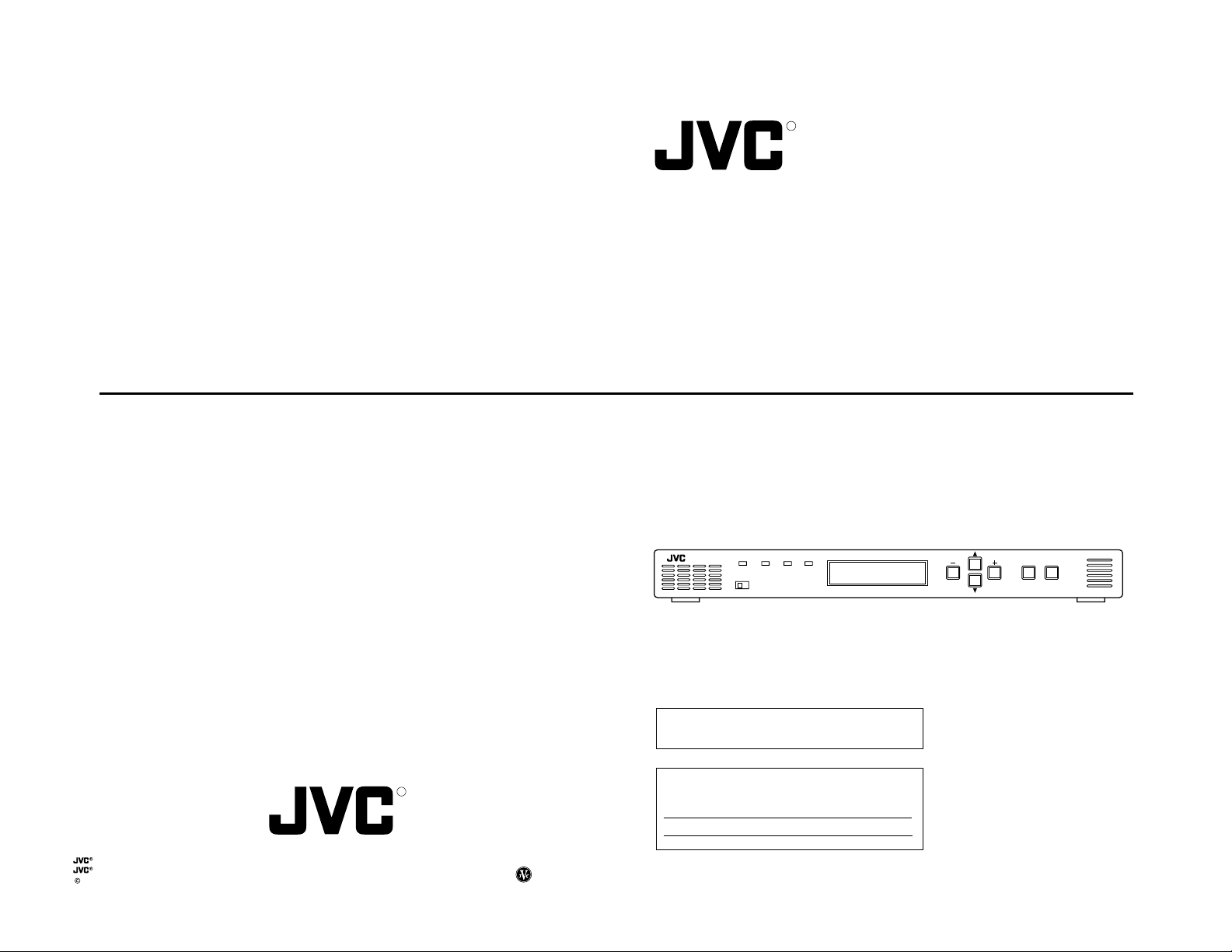
BC-D2300U HDTV UPCONVERTER
HDTV UPCONVERTER
BC-D2300U
R
INSTRUCTIONS
VICTOR COMPANY OF JAPAN, LIMITED
is a registered trademark owned by VICTOR COMPANY OF JAPAN, LTD.
is a registered trademark in Japan, the U.S.A., the U.K. and many other countries.
2001 VICTOR COMPANY OF JAPAN, LIMITED
POWER
STATUS INPUT SYNC
LOCAL REMOTE
Thank you for purchasing this JVC product. Before operating
this unit, please read the instructions carefully to ensure the
best possible performance.
For Customer Use:
R
Printed in Japan
SS961574-002
Enter below the Serial No. which is located on the top cover.
Retain this information for future reference.
Model No. BC-D2300U
Serial No.
This instruction book is made from
100% recycled paper.
BC-D2300U HDTV UP CONVERTER
ENTER ESC
MENU
SS961574-002
Page 2
SAFETY PRECAUTIONS
1. Read all of these instructions.
2. Save these instructions for later use.
3. All warnings on the product and in the operating instructions should be adhered to.
4. Unplug this appliance system from the wall outlet before cleaning. Do not use liquid cleaners or aerosol cleaners.
Use a damp cloth for cleaning.
5. Do not use attachments not recommended by the appliance manufacturer as they may cause hazards.
6. Do not use this appliance near water – for example, near a bathtub, washbowl, kitchen sink, or laundry tub, in a wet
basement, or near a swimming pool, etc.
7. Do not place this appliance on an unstable cart, stand, or table. The appliance may fall, causing serious injury to a child or adult, and serious damage to the appliance.
Use only with a cart or stand recommended by the manufacturer, or sold with the appliance.
Wall or shelf mounting should follow the manufacturer’s instructions, and should use a mounting kit approved by the manufacturer.
An appliance and cart combination should be moved with care. Quick stops, excessive force,
and uneven surfaces may cause the appliance and cart combination to overturn.
8. Slots and openings in the cabinet and the back or bottom are provided for ventilation, and to
insure reliable operation of the appliance and to protect it from overheating, these openings
must not be blocked or covered. The openings should never be blocked by placing the appliance on a bed, sofa,
rug, or other similar surface. This appliance should never be placed near or over a radiator or heat register. This
appliance should not be placed in a built-in installation such as a bookcase unless proper ventilation is provided.
9. This appliance should be operated only from the type of power source indicated on the marking label. If you are not
sure of the type of power supplied to your home, consult your dealer or local power company. For appliance
designed to operate from battery power, refer to the operating instructions.
10. This appliance system is equipped with a 3-wire grounding type plug (a plug having a third (grounding) pin). This
plug will only fit into a grounding-type power outlet. This is a safety feature. If you are unable to insert the plug into
the outlet, contact your electrician to replace your obsolete outlet. Do not defeat the safety purpose of the grounding plug.
11. For added protection for this product during a lightning storm, or when it is left unattended and unused for long
periods of time, unplug it from the wall outlet and disconnect the antenna or cable system. This will prevent damage to the product due to lightning and power-line surges.
12. Do not allow anything to rest on the power cord. Do not locate this appliance where the cord will be abused by
persons walking on it.
13. Follow all warnings and instructions marked on the appliance.
14. Do not overload wall outlets and extension cords as this can result in fire or electric shock.
15. Never push objects of any kind into this appliance through cabinet slots as they may touch dangerous voltage
points or short out parts that could result in a fire or electric shock. Never spill liquid of any kind on the appliance.
16. Do not attempt to service this appliance yourself as opening or removing covers may expose you to dangerous
voltage or other hazards. Refer all servicing to qualified service personnel.
17. Unplug this appliance from the wall outlet and refer servicing to qualified service personnel under the following
conditions:
a. When the power cord or plug is damaged or frayed.
b. If liquid has been spilled into the appliance.
c. If the appliance has been exposed to rain or water.
d. If the appliance does not operate normally by following the operating instructions. Adjust only those controls
that are covered by the operating instructions as improper adjustment of other controls may result in damage
and will often require extensive work by a qualified technician to restore the appliance to normal operation.
e. If the appliance has been dropped or the cabinet has been damaged.
f. When the appliance exhibits a distinct change in performance – this indicates a need for service.
18. When replacement parts are required, be sure the service technician has used replacement parts specified by the
manufacturer that have the same characteristics as the original part. Unauthorized substitutions may result in fire,
electric shock, or other hazards.
19. Upon completion of any service or repairs to this appliance, ask the service technician to perform routine safety
checks to determine that the appliance is in safe operating condition.
CAUTION ATTENTION
RISK OF ELECTRIC SHOCK
DO NOT OPEN
CAUTION: TO REDUCE THE RISK OF ELECTRIC SHOCK,
WARNING:
TO REDUCE THE RISK OF FIRE OR ELECTRIC
SHOCK, DO NOT EXPOSE THIS APPLIANCE
TO RAIN OR MOISTURE.
DO NOT REMOVE COVER (OR BACK).
NO USER-SERVICEABLE PARTS INSIDE.
REFER SERVICING TO QUALIFIED SERVICE PERSONNEL
The lightning flash with arrowhead symbol, within an
equilateral triangle, is intended to alert the user to the
presence of uninsulated “dangerous voltage” within
the product’s enclosure that may be of sufficient
magnitude to constitute a risk of electric shock to
persons.
The exclamation point within an equilateral triangle is
intended to alert the user to the presence of important
operating and maintenance (servicing) instructions in
the literature accompanying the appliance.
This unit should be used with 120 V AC only.
CAUTION:
To prevent electric shocks and fire hazards, do NOT
use any other power source.
NOTE:
The rating plate (serial number plate) is on the top cover.
INFORMATION
This equipment has been tested and found to comply with the
limits for a Class A digital device, pursuant to Part 15 of the
FCC Rules. These limits are designed to provide reasonable
protection against harmful interference when the eqipment is
operated in a commercial environment. This equipment
generates, uses, and can radiate radio frequency energy and, if
not installed and used in accordance with the instruction
manual, may cause harmful interference to radio
communications.
Operation of this eqipment in a residential area is likely to
cause harmful interference in which case the user will be
required to correct the interference at his own expense.
CAUTION
CHANGES OR MODIFICATIONS NOT APPROVED BY JVC
COULD VOID USER’S AUTHORITY TO OPERATE THE
EQUIPMENT.
This Class A digital apparatus meets all requirements of the
canadian Interference-Causing Eqipment Regulations.
RISQUE D'ELECTROCUTION
NE PAS OUVRIR
ATTENTION: POUR EVITER TOUT RISQUE D'ELECTROCUTION
AVERTISSEMENT:
POUR EVITER LES RISQUES D'INCENDIE OU
D'ELECTROCUTION, NE PAS EXPOSER
L'APPAREIL A L'HUMIDITE OU A LA PLUIE.
Ce magnétoscope ne doit être utilisé que sur du
courant alternatif en 120 V.
ATTENTION:
Afin d'éviter tout resque d'incendie ou
d'électrocution, ne pas utiliser d'autres sources
d'alimentation électrique.
REMARQUE:
La plaque d'identification (numéro de série) se trouve sur le
panneau arrière de l'appareil.
Cet appareil numérique de la classe A respecte toutes les
exigences du Reglement sur le matériel brouilleur du Canada.
NE PAS OUVRIR LE BOITER.
AUCUNE PIECE INTERIEURE N'EST
A REGLER PAR L'UTILISATEUR.
SE REFERER A UN AGENT QUALIFIE EN CAS DE PROBLEME.
Le symbole de l’éclair à l’intérieur d'un triangle
équilatéral est destiné à alerter l’utilisateur sur la
présence d’une “tension dangereuse” non isolée
dans le boîtier du produit. Cette tension est suffisante
pour provoquer l’électrocution de personnes.
Le point d’exclamation à l’intérieur d’un triangle
équilatéral est destiné à alerter l’utilisateur sur la
présence d’opérations d’entretien importantes au
sujet desquelles des renseignements se trouvent
dans le manuel d’instructions.
*Ces symboles ne sont utilisés qu’aux Etats-Unis.
2
3
Page 3
CONTENTS
Major features.................................................................. 4
Notes on settings and use ............................................. 4
Handling precautions ..................................................... 4
Installation in a rack........................................................ 4
Controls, indicators and connectors
Front panel .....................................................................5
Rear panel...................................................................... 6
Menu settings
Setting the menu ............................................................7
Sub menu....................................................................... 7
Storing menu settings in memory of this unit ................. 8
Recalling stored menu settings or factory default
settings........................................................................... 8
Entering characters ........................................................9
Menu contents.............................................................. 10
Others
Error output .................................................................. 16
Rear panel connectors .................................................18
Installing the power cable hook.................................... 18
Specifications ...............................................................19
Supplement ..................................................................21
Optional software
For optional software, consult your JVC dealer. Using
it without formal procedures is illegal.
MAJOR FEATURES
This unit converts SMPTE259M-standard SD digital serial signal
input to the SMPTE292M-standard (1080I or 720P) HD digital
serial signal for output.
Conversion modes are provided for input NTSC video signals
with an aspect ratio of 4:3 (standard), in the letter box format or
squeezed.
The delay time for video conversion is added to the embedded
audio to synchronize audio and video for output.
Input signal can be cropped (in the 4:3 mode, independently for
the left and right sides)
Background color can be set with hue, saturation and lightness.
It is possible to set or show the model name (up to 10
characters).
Each function can be set on the front panel with the LCD. The
unit can also be remote-controlled via the 9-pin connector on the
rear panel (RS-485 or RS-232C).
Menu settings can be saved in memory and loaded from
memory.
Four independent memories are provided to store menu settings.
Stored menu settings can be recalled as required.
Compact design allows this unit to be installed in a 1U EIA rack.
Color bar output possible.
External reference sync signal input connector
Three video/audio output connectors
Enhancer (contour correction), motion sensitivity, background
color, screen horizontal/vertical position and system phase can
be adjusted.
Error indication and alarm signal output function
Color correction function (option)
Variable enhancer (option)
NOTES ON SETTINGS
AND USE
● When the menu item <Reference> is set to [INPUT] and there is
no SD input signal, output video signals may be distorted. In this
case, input external sync signals and set <Reference> to [BB] or
[HD-SYNC]. (
● When the menu item <Reference> is set to [BB] or [HD-SYNC]
and these external sync signals are not input or are incorrect,
output video signals may be distorted. In this case, system
phase cannot be assured. (
4
p. 10).
p.10)
HANDLING
PRECAUTIONS
● Avoid using this unit in places subject to the following conditions:
– direct sunlight
– high humidity and dust
– vibrations
– extreme heat
These conditions can cause problems and may damage the unit.
● Influence of strong electric waves and magnetism
Noise may appear on the screen when used in places close to a
transmission antenna, or in places near transformers and motors
where strong magnetism can occur.
● This equipment is meant for use exclusively in commercial and
industrial applications. If used at home, it may cause
interference with radio and television reception.
● To save electricity, shut off the power when the unit is not in use.
● Use the supplied power cable for this unit.
● Do not place heavy objects such as a television monitor on top of
the unit. Doing so could cause damage or adversely affect
performance.
● Do not put any foreign objects into the unit.
● Do not disassemble the unit or try to modify it.
● Do not block the ventilation openings.
● Change the cooling fan about three years after installation of the
unit.
● When cleaning the cabinet, wipe it with soft cloth. Do not use
benzene or thinner as these may deform or discolor the cabinet
surface. To remove excessive dirt, clean the unit with a mild
detergent diluted with water, then wipe it with dry cloth.
● Do not use the unit in an environment exposed to gases
generated by chemicals or organic solvents.
INST ALLATION IN A
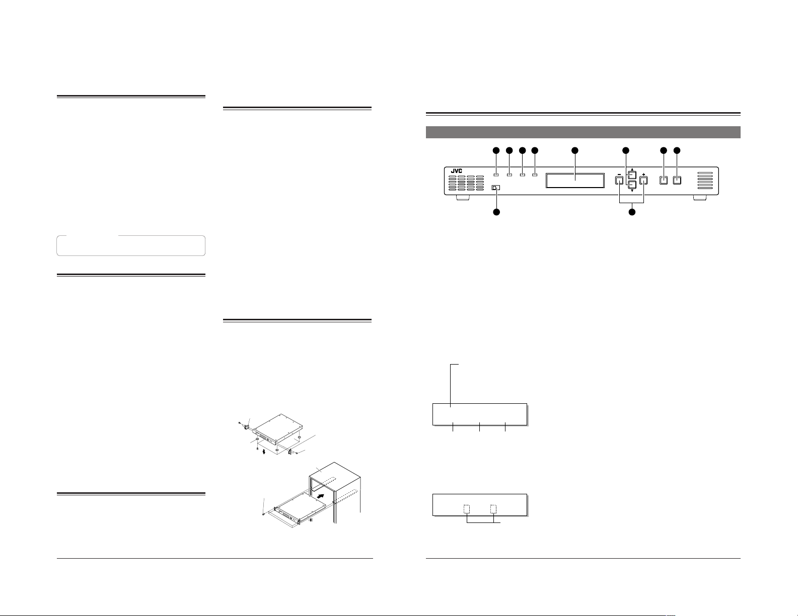
RACK
This unit can be installed in EIA standard rack. Ensure
sufficient rack strength by attaching L-metal supports on
both sides of the rack on which you will place the unit.
1.
Detach the four feet on the base of the unit.
2.
Install the supplied rack mount brackets on both sides of
front panel using the four supplied screws (M4).
3.
Set this unit on the rack, and fix the rack mount brackets
onto the rack using the four supplied screws (M5).
2.
Rack mount
bracket
2.
Rack mount
1.
Foot
3.
Supplied
screw (M5) x 4
See ‘‘Supplement’’ on page 21.
2.
Supplied
screw (M4) x 4
EIA rack
bracket
CONTROLS, INDICATORS AND
CONNECTORS
Front panel
21 3 4
POWER
STATUS INPUT SYNC
LOCAL REMOTE
1
[POWER] indicator
Lights green when power is supplied to this unit.
2
[STATUS] indicator
Normally lights green. Lights orange in the menu setting
mode, when the set value is changed or the set data is
transmitted to this unit. When the transmission is
complete, this indicator lights green again. When errors
occur in hardware, etc., this indicator lights red.
3
[INPUT] indicator
Normally lights green. When no signal is input, this
indicator lights orange. If there is an error in the input
signals, this indicator lights red.
4
[SYNC] indicator
Normally lights green. If a sync system-related error
occurs, this indicator lights red.
● For details on error indicators, see page 17.
5
Display
● When power is applied, the input/output or screen
display mode is shown. (Normal display mode)
Model name:
The model name can be set with the
menu (up to 10 characters). In the
remote mode, the remote ID number
(1 – 31) is shown following the model
name.
(e.g.) BC-D2300 ID:
BC– D2300
[ D1 |1080| 4: 3]
Input form
Memoranda:
● The screen conversion mode can be selected with
● Output form can be selected with menu <Output>.
● When menu <Color Correction> is set to “ON” or
Output form
menu <Output Mode>.
p. 10.
<Colorimetry> is set to “OFF”, the normal display
changes as follows.
Screen conversion mode
p. 10.
BC– D2300
[ D1 /1080/ 4: 3]
8
● Press the
item in the menu setting mode.
● If an error occurs in the normal display mode, a
description of the error is shown.
[ENTER/MENU] button to display the
Change
p. 17.
5 7 8 9
610
6
[+/–] button
Press this button to change the set value for a menu
item in the menu setting mode.
7 [/] button
Press this button to select the menu item in the menu
setting mode.
8
[ENTER/MENU] button
● In the normal display mode, press this button to
engage the menu setting mode.
● In the menu setting mode, press this button to enter
the set value for the following menu items. (? is
shown.)
Output Mode item
Output item
Profile Save item
Profile Load item
● Use to enter the sub menu. ([ENTER] is shown.)
9
[ESC] button
In the menu setting mode, press this button to restore
the normal display mode.
Memorandum:
● To use the menu setting, refer to pages 7 to 9.
0
[LOCAL/REMOTE] switch
Use to select LOCAL or REMOTE to operate this unit.
LOCAL : Set to this position to operate this unit with
the operation buttons on this unit.
REMOTE : Set to this position to remote-control this unit
via the [REMOTE IN] connector or [ALARM]
connector on the rear panel. Also, set to this
position to lock the front panel’s operation
buttons.
● The factory preset is LOCAL.
BC-D2300U HDTV UP CONVERTER
ENTER ESC
MENU
5
Page 4
FUSE
96
5
1
96
5
1
96
5
1
CONTROLS, INDICA TORS AND CONNECTORS
Rear panel
6
1
2
3
FUSE
ON
1.6A(125V)
OFF
AC IN
POWER
4
IN
CN1
SDI
OUT
5
1
[AC IN] power input connector
Connect to an AC 120 V, 50 Hz/60 Hz power outlet with
the provided power cable. Attach the provided hook
beforehand.
2
[POWER] switch
Use to turn the power on/off. When the power is turned
on, the indicators and display on the front panel light up.
3
Fuse holder
The fuse is built in. For fuse replacement, consult your
nearest JVC dealer.
4
[SDI IN] connector
Input a SMPTE259M standard SD digital serial signal
(NTSC). Compatible with embedded audio signals as
well. Embedded 20-bit digital audio with 48 kHz
sampling frequency can be input with 4 channels.
5
[SDI OUT] connector
Active through output of digital serial video/audio
signals input to the
6
[CVBS] connector
Input analog composite signals (NTSC). The optional
BC-D231 (D2/analog optional board) is required.
7
[Y/Pr/Pb] connectors
Input analog component signals (NTSC) to each
connector. The optional BC-D231 (D2/analog optional
board) is required.
Note:
● The [CVBS] and [Y/Pr/Pb] connectors are enabled
8
[REF] external reference sync signal input
connectors (loop-through)
Input external reference sync signal. As these
connectors use a loop-through system, signals input to
one connector can be distributed from another connector
to the other equipment.
Memoranda:
● When signal distribution is not required or this unit is a
● When the signals input to these connectors are used
● When the signals input to these connectors are used
p. 18.
4
[SDI IN] connector is possible.
only when the BC-D231 optional board is installed.
For details, refer to the BC-D231 instruction manual.
terminating device, terminate this unit with the external
75-ohm terminator.
as a reference sync signal, set the menu switch
<Reference> to “B.B” or “HD SYNC”.
as a reference sync signal, synchronize the input
signal with the reference sync signal so that the V
sync is within ±300 µs.
p. 10.
8 9
Pr
CVBS
Pb
Y
7
9
[HD SERIAL OUT] HD digital serial output
connectors (3 lines)
Output SMPTE292M standard HD digital serial signals.
Output embedded digital audio signals with 20-bit
48 kHz sampling frequency as 4-channel signals.
0
[ALARM] connector ... D-sub 9-pin (male)
● This connector is an alarm output (relay contact)
connector. When a problem occurs with this unit, an
alarm signal is output.
● When menu switch <Remote Port> is set to “ALARM”,
remote operation via the RS-232C is possible.
To remote-control this unit via this connector, set the
[LOCAL/REMOTE] switch on the front panel to
“REMOTE”.
!
[REMOTE-IN] connector ... D-sub 9-pin (female)
This connector is the input connector for remote-control
device.
Connect this connector to a device conforming to the
RS-485 serial interface standard.
Memoranda:
● To use this connector, set menu switch <Remote Port>
to “REMOTE-IN”.
● Set the remote ID and remote transmission speed with
the menu switches.
● To remote-control this unit, set the [LOCAL/REMOTE]
switch on the front panel to “REMOTE”.
@
[REMOTE-OUT] connector ... D-sub 9-pin
(female)
Outputs the control signals input to the ! [REMOTE-IN]
connector or
ing to the RS-485 serial interface. Connect this connector to the [REMOTE IN] connector of another device.
Up to 31 devices can be connected in series with this
connection.
#
[TERMINATE] switch
This is the terminating switch for remote control signals.
With a series connection, set this switch to “ON” when
this unit is terminated or control signals from the
[ALARM] connector are received.
● The factory preset is “OFF”.
23
ALARM
1
REMOTE-IN
REF
LOOP
THROUGH
10 11 12 13
0
[ALARM] connector as signals conform-
HD SERIAL OUT
OFF
REMOTE-OUT TERMINATE
MENU SETTINGS
You can set various functions on the menu. Settings are stored and automatically activated whenever you turn on the power.
Up to four independent menu settings can be stored in the unit’s memory and recalled at any time. You can also restore the
default factory settings at any time. The menu is shown on the display.
Setting the menu
2, 5
BC-D2300U HDTV UP CONVERTER
4
[+] button
[ENTER/MENU] button
ENTER ESC
MENU
6
[ESC] button
[STATUS] indicator Display
POWER
ON
STATUS INPUT SYNC
LOCAL REMOTE
4
Normal display
BC– D2300
1
[ D1 |1080| 4: 3]
Menu display
Output Mode
/
[
]
The [–] button
button
is effective.
Item
Press the [ENTER/
MENU] button.
4:3
Setting
The [+] button
is effective.
2
3
4
Re f e r e nc e
I NPUT
Ou t p u t M
Normal display
LETToEdReBOX ?
Press the [ENTER/MENU]
button to enter the value.
The “?”goes out.
Press the [ESC] button.
Refer to the next page for details on how to store menu setting
contents in memory.
5
BC– D2300
[ D1 |1080| LB ]
3
[] button
[–] button
3
[] button
Turn the power of this unit ON.
The model name, input/output and screen display mode are
shown on the display (normal mode).
Press the [ENTER/MENU] button to engage menu
setting mode.
● The display shows the menu. The current setting is shown.
Press the [
]
or [] button to select the menu item.
Press the [+] or [–] button to change the setting.
Memoranda:
● When “[” is shown at the right of the display, press the
[+] button to change the setting. When “p“ is shown at the
left of the display, press the [–] button.
● When “?“ appears after the value you want to set, press the
[ENTER/MENU] button to enter the setting.
● When the setting is changed, the [STATUS] indicator lights
orange while the set data is transmitted to this unit. When the
transmission is complete, this indicator lights green.
Press the [ESC] button to end menu setting.
● Your changes are stored in memory and the display returns to
normal.
Note:
If power is turned OFF without pressing the [ESC] button,
setting changes are not saved.
Sub menu
Menu display
C
olor Co[rrecti
[ENTER/MENU] button
Sub menu
Wh i t e L e ve l
/
[
]
button
ON ENT E
[ESC] button
on
R]
0
0
Exact settings for variable enhancer (option), color correction
(option) and administration can be done on the sub menu.
1.
When setting the variable enhancer or color correction to ON,
or selecting administration, [ENTER] is shown on the display.
To enter the sub menu, press the [ENTER/MENU] button.
2.
Set each menu item in the same way as with the ordinary
menu.
3.
Press the [ESC] button to go to the upper menu by one.
6
7
Page 5

MENU SETTINGS
Storing menu settings in memory of this unit
Normal display
BC– D2300
[ D1 | 1080| 4 :3 ]
ENTER/MENU
Profile Save
Menu display
ESC
Prof i leMESMaOvRe
Y2?
ENTER/MENU
Check screen
ESC
Prof i le
MEMORY 2SSaavveeOK?
ENTER/MENU
Completion screen
Prof i le SavSe
aved.
ENTER/MENU or ESC
1 Press the [ENTER/MENU] button to engage the Menu
Display mode.
2
Select Profile Save with the [] or [] button.
3
Select the memory number where you want to store
the menu settings with the [+] or [–] button (one of
MEMORY 1 to 4).
● The “?” is added to the end of the selected memory number.
4
Press the [ENTER/MENU] button.
● The check screen is shown for confirmation.
5
Press the [ENTER/MENU] button again to confirm the
setting.
● The menu settings are stored in the selected memory. Once
the settings have been stored, the completion screen is
shown.
Memorandum:
● When the check screen is shown, press the [ESC] button to
cancel it. The previous Profile Save menu setting display is
restored.
6
Press the [ENTER/MENU] button or [ESC] button.
● Menu setting display is restored.
7
Press the [ESC] button to restore the normal display.
Note:
● Settings for Remote ID, Remote Speed and Remote Port are
not stored in memory for each Profile. One value is used for
all profiles.
Recalling stored menu settings or factory default settings
Normal display
BC– D2300
[ D1 | 1080| 4 :3 ]
ENTER/MENU
Profile Load
Menu display
ESC
Prof i leMELMoOaRd
Y2?
ENTER/MENU ESC
Check screen
Prof i le
MEMORY 2LLooaaddOK?
ENTER/MENU
Completion screen
Prof i le LoLaod
aded.
ENTER/MENU or ESC
1
Press the [ENTER/MENU] button to engage the Menu
Display mode.
2
Select Profile Load with the [] or [] button.
3
Select the memory to be recalled (MEMORY 1 to 4,
DEFAULT) with the [+] or [–] button.
When DEFAULT is selected, the factory setting is
recalled.
4
Press the [ENTER/MENU] button.
● Display the check screen for confirmation.
5
Press the [ENTER/MENU] button again to confirm.
● The selected settings are recalled. When completed, the
completion display is shown.
Memorandum:
● When the check screen is shown, press the [ESC] button to
cancel it. The previous Profile Load menu setting display is
restored.
6
Press the [ENTER/MENU] button or [ESC] button.
● Menu setting display is restored and the recalled menu
settings are activated.
7
Press the [ESC] button to restore the normal display.
Memorandum:
● The factory default settings are stored in MEMORY 1 to 4.
Entering characters
Enter characters to set the model name and the [License key].
Display
POWER
STATUS INPUT SYNC
LOCAL REMOTE
Name menu display
Name
[CB-2D 300 ]
ENTER/MENU
Edit mode
Name EDI
[CB-2D 300 ]
Cursor
ENTER/MENU
ESC
T
1, 3 [
3 [–] button
1, 3
[
An example of model name setting is shown below.
1
Select [Name] in the sub menu for administration.
● The currently-set device name is shown.
2
Press the [ENTER/MENU] button.
● The Edit mode is engaged and the cursor appears.
3
Move the cursor with the [+] or [–] button.
Change the characters with [
10 characters).
4
Press the [ENTER/MENU] button to store the device
name in memory.
● The setting is refreshed and the name menu display is
restored.
Press the [ESC] button to interrupt editing and restore the
previous setting.
● The changed setting is canceled and the name menu is
restored.
5
To restore the normal display, press the [ESC]
button.
2, 4 [ENTER/MENU] button
] button
BC-D2300U HDTV UP CONVERTER
ENTER ESC
MENU
3 [+] button
] button
4, 5 [ESC] button
] or [] button (up to
8
9
Page 6

MENU SETTINGS
Menu contents
Items
Output Mode
Note:
● The following menu item values
can be saved for each setting
mode.
• V Position
• Motion Sense
• Enhance Level
• Variable Enhancer and 5-related
item (option)
When the setting for Output Mode is
changed, check the setting of the
above menu items.
Output
Reference
Note:
● System Phase settings can be
saved for each of these item
settings.
System Phase
H Position
H Crop (Left)
H Crop (Right)
Settings
[4:3]
LETTER BOX
SQUEEZE
[1080I]
720P
[INPUT]
BB
HD-SYNC
–300
…
[0]
300
–120
………
[0]
120
[0]
100
–100
……
[0]
[ ]: Factory Setting
Sets the HD Conversion mode according to the NTSC video source.
4 : 3 : When the input video has an aspect ratio of 4:3, it is converted
LETTER BOX : When the input video is in the LETTER BOX format, it is
SQUEEZE : When the input video has been “squeezed” for display on 4:3
Sets the output video format.
1080I : Effective 1080 scanning lines, interlace.
720P : Effective 720 scanning lines, progressive.
Selects the reference sync signal.
INPUT : Synchronizes with the video signal input to the [SDI IN]
BB : Synchronizes with the black burst signal input to the [REF]
HD-SYNC : Synchronizes with the tri-sync input to the [REF] connector of
Note:
● When this is set to “BB” or “HD-SYNC”, the V sync position of these external
signals and video input signals must synchronize within ±300 µs..
Sets the HD output signal phase for the reference sync signal selected with
<Reference>.
(Variation for ±300 is equivalent to about ±4 µs.)
Adjusts the picture’s horizontal display position (varies in ±120 x 2 pixels).
● This item is enabled only when the Output Mode is set to 4:3.
● When the <Output> item is set to “720P”, the actual display position area is ±80
x 2 pixels. Keep in mind that this is different from the value set with the menu.
Sets the crop width at the left of the input picture.
● This item is enabled only when the Output Mode is set to 4:3.
For the part cropped, the background color is shown.
Sets the crop width at the right of the input picture.
● This item is enabled only when the Output Mode is set to 4:3.
For the part cropped, the background color is shown.
to HD pictures without changing the aspect ratio for output. In
this case, the side panels appear on the screen.
converted to HD pictures with an aspect ratio of 16:9 for output.
screens, it is converted to HD pictures with an aspect ratio of
16:9 for output.
NTSC
HD
connector of this unit.
connector of this unit.
this unit. Tri-sync must be input in the same signal form as the
output setting.
Contents
4 : 3 LETTER BOX SQUEEZE
Side panel
Menu contents (contd.)
The items in the shaded area are shown when the optional software is installed. [ ]: Factory Setting
Items
V Position
Motion Sense
Enhance Level
Variable
Enhancer
Enhance Level
Enhance Freq
Cut Off Freq
Threshold
Noise Reduction
Settings
–63
………
[0]
63
0
[8]
15
–5
……
[0]
…
15
OFF
[ON]
–5
…………
[0]
15
2
[4]
5
3
[7]
[0]
…
15
[OFF]
ON
Adjusts the picture’s vertical position (varies in ±63 lines).
Note:
● When <Output Mode> is set to “4:3” or “SQUEEZE”, the actual variable range
is ±3 lines. Keep in mind that this is different from the value set with the menu.
Motion detection sensitivity adjustment
Sets the optimum conversion sensitivity according to the input material.
Normally use the factory setting.
Adjusts the enhancer (contour compensation) of the video output signal.
Varies in 20 steps. Use this 2-dimensionally (horizontal and vertical).
When the optional variable enhancer function is enabled, the variable enhancer
menu is shown instead of this item.
Sets ON/OFF of the variable enhancer function. When set to “OFF”, the
enhancer is disabled. When set to “ON”, the variable enhancer functions based
on the values of the following five items.
The following five parameters can be displayed and set on the sub menu by
pressing the [ENTER/MENU] button. (
● This item is shown only when the optional variable enhancer function is
enabled.
Sets the enhancement level.
● This item is shown when the optional variable enhancer function is enabled
and <Variable Enhancer> is set to “ON”.
Sets the frequency of the input signal to be enhanced.
● This item is shown when the optional variable enhancer function is enabled
and <Variable Enhancer> is set to “ON”.
Sets the band limit frequency of the input signal. When set to 7 (MHz), band
limitation is not performed.
Note:
When the <Cut Off Freq> setting is smaller than the <Enhance Freq> setting, the
enhancement function is disabled.
● This item is shown when the optional variable enhancer function is enabled
and <Variable Enhancer> is set to “ON”.
Sets the threshold of the enhancement effect. If the enhancement effect is
applied excessively, even low-level noise contained in the original picture will be
emphasized.
With this setting, the enhancement of a small amount of noise can be
suppressed to emphasize only the contour.
● This item is shown when the optional variable enhancer function is enabled
and <Variable Enhancer> is set to “ON”.
When this item is set to “ON”, a small amount of noise lower than the threshold
level can be suppressed. The larger the threshold setting, the larger the effect to
suppress noise.
Note:
This function has no effect unless <Enhance Level> is set to the larger value.
● This item is shown when the optional variable enhancer function is enabled
and <Variable Enhancer> is set to “ON”.
Contents
p. 7 for sub menu)
10
11
Page 7

MENU SETTINGS
Menu contents (contd.)
Items
Back Color Mode
Back Color (Y)
Back Color (Cb)
Back Color (Cr)
Back Color (L)
Back Color (S)
Back Color (H)
Settings
[YCbCr]
HSL
[64]
………
940
64
[512]
960
64
[512]
…………
960
[0]
100
[0]
100
[0]
…
359
[ ]: Factory Setting
Sets the method to specify the background color.
YCbCr : Sets the output value of the background color.
HSL : Sets the background color with the Hue, Saturation and Lightness
values.
Note:
● When this setting is changed, the following three menu settings also change.
In this case, the set value and color may be changed. If this setting is
changed, check the color on the screen again.
Varies the background color brightness. With 4:3 aspect ratio picture input, this
adjustment is applied to the side panels of the picture output.
Set this by checking the screen.
● This item is shown only when the Back Color Mode is set to YCbCr.
Varies the blue of the background color. With 4:3 aspect ratio picture input, this
adjustment is applied to the side panels of the picture output.
Set this by checking the screen.
● This item is shown only when the Back Color Mode is set to YCbCr.
Varies the red of the background color. With 4:3 aspect ratio picture input, this
adjustment is applied to the side panels of the picture output.
Set this by checking the screen.
● This item is shown only when the Back Color Mode is set to YCbCr.
Sets the background color lightness. With 4:3 aspect ratio picture input, this
adjustment is applied to the side panels of the picture output.
Set this by checking the screen.
● This item is shown only when the Back Color Mode is set to HSL.
Sets the background color saturation. With 0, monochrome is shown. The larger
the number, the higher the saturation.
Note:
● The saturation actually output is limited by the setting of the Back Color (L).
Even though the Back Color (S) is set to 100, the picture will be monochrome if
the Back Color (L) is set to 0 (black) or 100 (white).
● This item is shown only when the Back Color Mode is set to HSL.
Sets the background color hue. In most cases, the following colors can be
obtained.
0: Red, 120: Green, 240: Blue
● This item is shown only when the Back Color Mode is set to HSL.
Contents
Menu contents (contd.)
The items in the shaded area are shown when the optional software is installed. [ ]: Factory Setting
Items
Color Correction
White Level
Black Level
White Color (B)
White Color (R)
Back Color (B)
Back Color (R)
Phase
Chroma
Settings
[OFF]
ON
–100
…
[0]
………
100
–100
[0]
100
–100
……
[0]
100
–100
[0]
…………
100
–100
[0]
100
–100
………………
[0]
100
–179
[0]
180
–100
[0]
100
● This menu is shown when the optional color correction function is enabled.
Sets the color correction function ON/OFF.
With OFF, the color correction function is disabled.
With ON, the color is corrected based on the following 8 parameters (items).
When this function is set to ON, the normal display format changes. (
The following eight parameters are shown and set on the sub menu when
<Color Correction> is set to “ON” and the [ENTER/MENU] button is pressed.
Adjusts the high brightness level of the input picture.
● Can be set when the Color Correction is set to ON.
Adjusts the low brightness level of the input picture.
● Can be set when the Color Correction is set to ON.
Adjusts the blue of the high brightness section of the input picture.
● Can be set when the Color Correction is set to ON.
Adjusts the red of the high brightness section of the input picture.
● Can be set when the Color Correction is set to ON.
Adjusts the blue of the low brightness section of the input picture.
● Can be set when the Color Correction is set to ON.
Adjusts the red of the low brightness section of the input picture.
● Can be set when the Color Correction is set to ON.
Adjusts the phase of the input picture.
● Can be set when the Color Correction is set to ON.
Adjusts the chroma of the input picture.
With –100, the picture becomes black-and-white (monochrome).
● Can be set when the Color Correction is set to ON.
Contents
p. 5)
12
13
Page 8

MENU SETTINGS
Menu contents (contd.)
Items
Colorimetry
Out Delay
Audio Group
Audio Delay
Profile Save
Profile Load
Color Bar
Settings
OFF
[ON]
[1FRAME]
1FRAME-90H
NO USE
[1]
2
3
4
–30
…
[0]
…
30
MEMORY 1
MEMORY 2
MEMORY 3
MEMORY 4
MEMORY 1
MEMORY 2
MEMORY 3
MEMORY 4
DEFAULT
[OFF]
ON
[ ]: Factory Setting
Turns the colorimetry parameter conversion function ON/OFF. This function
allows SD (ITU-R601) to be converted to HD (ITU-R709).
Normally, set to ON.
When this function is set to OFF, the normal display format changes. ( p. 5)
Sets the delay time from the input to the output.
1FRAME : Delays by 1 frame (33.37 ms).
1FRAME-90H: Delays by 1 frame -2.67 ms for 1080I. Delays by 1 frame
Selects the audio signal group (groups 1 to 4) multiplexed on the SD digital serial
input signal.
If audio is not used, select No Use.
Sets the delay for the audio signal multiplexed on the SD digital serial input
signal.
Adjustment of ±30 (msec.) is possible with respect to the delay time set with
<Out Delay>.
Four independent memories are provided to store menu settings.
Selects the memory to be used to store the set menu contents.
* Items in the administration sub menu are not stored in memory.
Recalls menu setting stored in memory.
When set to DEFAULT, menu setting set before shipment is recalled.
When set to ON, the built-in color bar (7-line color bar) is output regardless of the
input.
The color bar output turns off automatically when you quit this menu.
-2.00 ms for 720P.
Contents
Menu contents (contd.)
Items
Administration
Remote ID
Remote Speed
Remote Port
Active Line
Alarm
Name
Version
Serial No.
License key
Running Time
Settings
[1]
…
31
9600
19200
[38400]
[REMOTE-IN]
ALARM
480
[486]
OFF
[ON]
[BC-D2300]
[ ]: Factory Setting
Press the [ENTER/MENU] button to enter the administration sub menu.
The following nine items can be set on the administration sub menu.
Sets the remote ID of this unit to remote-control this unit from the Host.
Sets the transmission speed (bit/s) of the remote control signal.
Selects the connection port for the host when this unit is remote-controlled.
REMOTE-IN : Connects RS-485 to the [REMOTE-IN] port.
ALARM : Connect the RS-232C to the [ALARM] port.
Sets the number of effective lines of the input signal when <Output> is set to
“1080I”.
With <Output> set to “720P”, the number is fixed at 480 lines (on the menu, --- is
shown).
When set to “OFF”, the output from the rear panel’s [ALARM] connector stops
(always open except when power is turned off).
Sets the device name that will be shown in the normal display.
For setting, refer to page 9.
Shows the firmware version of this unit.
Shows the serial number of this unit.
Sets the license key to enable optional features such as the variable enhancer
and color compensation function.
For setting, refer to page 9.
To obtain the license key, consult your JVC dealer.
Shows the approx. number of operating days of this unit.
Press the [ENTER/MENU] button twice to clear this number to 0.
Use this as a guide for determining when to replace the fan.
Set to this position to remote-control this unit via the
[REMOTE-IN] connector.
Set to this position to remote-control this unit via the [ALARM]
connector.
Contents
14
15
Page 9

OTHERS
FUSE
96
5
1
96
5
1
96
5
1
When an abnormality is detected, error notification is provided by LED illumination, error indication on the display and error
output to the [ALARM] connector.
Error output
1. LED lighting
The [STATUS], [INPUT] or [SYNC] indicator on the front panel
STATUS INPUT SYNC
POWER
STATUS INPUT SYNC
LOCAL REMOTE
Error indication
Fan
V. D a
ON
OFF
AC IN
POWER
D[1
D[1
FUSE
1.6A(125V)
Err
a
t
CN1
Display
o
108 4: 3 ]0
E
108 4: 3 ]0
CVBS
IN
SDI
Y
OUT
r
rror 03
REF
Pr
LOOP
THROUGH
Pb
ALARM
15
96
ALARM
Front panel
BC-D2300U HDTV UP CONVERTER
ENTER ESC
MENU
Rear panel
23
1
REMOTE-IN
REMOTE-OUT TERMINATE
HD SERIAL OUT
ON
OFF
lights orange (warning) or red (error), depending on the type of
error.
2. Display indication
The first line of the display shows a description of the error. When
the menu is displayed, errors are not shown.
Memoranda:
● With LOCAL, the error indication is shown when the error is
detected and goes out when the error is no longer detected.
With REMOTE, once an error is detected, the indication
remains (goes out when the switch is set to LOCAL).
● Error codes with 2 to 6 digits may be shown at the same time.
In this case, report the error codes to your JVC dealer.
3. [Alarm] connector output
2-line alarm output terminals are provided for the rear panel’s
[ALARM] connector. Terminals A and B are short-circuited (relay
contact) when an error occurs or the power is turned off. Normally,
these terminals are open. (For open and short-circuited conditions,
refer to the table on the next page.)
The maximum rated value is 30 V 0.5 A for AC/DC with noninductive load.
Pin assignment of the [ALARM] connector
Pin
number
Name Contents
1 NC Unconnected
2 (RD) (Reception data for maintenance)
3 (SD) (Transmission data for maintenance)
4 ALARM2-B Alarm output 2 B terminal
5 GND Signal ground
6 ALARM2-A Alarm output 2 A terminal
7 ALARM1-A Alarm output 1 A terminal
8 ALARM1-B Alarm output 1 B terminal
9 NC Unconnected
Error output (contd.)
Error indications and output contents
Error
indications
Power Error Abnormality in the power unit STATUS: Red Short- Open
Fan Error Abnormality in the fan motor
Data No-input No video and audio signal is input. INPUT: Orange Open Open
(warning)
V. Format Error Format error of the SDI input signals INPUT: Red Open ShortV. Data Error Error of video data in the SDI input signal
A. Data Error Error of audio data in the SDI input signal
REF No-input No external sync signal is input (note) SYNC: Red Short- Open
SD Unlock Synchronization is not possible due to incorrect
Ref Unlock Synchronization is not possible due to incorrect
video input signals
external sync signal input
Comm Error Abnormal remote communication STATUS: Red Short- Open
Device Error Abnormality in the internal device
—— Power is turned off. —— Short- Short-
Note: When an incorrect external sync signal is input, the REF No-input error indication may be shown.
When an error indication is shown, check the input signal and connections according to type of error indicated. When this
unit malfunctions, consult your nearest JVC authorized service agent.
on page 1-3.
Error contents LED ALARM 1 ALARM 2
circuited
circuited
circuited
circuited
circuited circuited
See "1.4 About Error Messages"
16
17
Page 10

OTHERS
Rear panel connectors
Names Functions Types Remarks
SDI IN SD digital serial signal input BNC
SDI OUT Active through output BNC
REF External sync input BNC
REF Loop-through BNC
HD SERIAL OUT 1 HD digital serial signal output BNC
HD SERIAL OUT 2 Same as above BNC
HD SERIAL OUT 3 Same as above BNC
CVBS Analog composite input BNC The optional BC-D231 is required.
Y Analog component Y input BNC
Pr Analog component Pr input BNC
Pb Analog component Pb input BNC
ALARM [ALARM] connector/RS-232C D-SUB 9-pin male, inch screw
REMOTE-IN Remote control input D-SUB 9-pin female, mm screw
REMOTE-OUT Remote control bridge D-SUB 9-pin female, mm screw
REMOTE-IN, REMOTE-OUT terminal pin assignment
1
5
9
Note:
● For the REMOTE connection, use a straight cable
which contains twisted paired lines for the signals of
TxA and TxB, RxA and RxB.
6
Pin Signal
number name
1NC— Unconnected
2 TxA O Transmission A RS-485
3 RxB I Reception B RS-485
4SG— Signal ground
5NC— Unconnected
6SG— Signal ground
7 TxB O Transmission B RS-485
8 RxA I Reception A RS-485
9NC— Unconnected
I/O Contents Remarks
Installing the power cable hook
1.
Before connecting the power cable, install the supplied hook as
shown on the left.
2.
After connecting the power cable, lower the hook to secure the
power cable in place.
Specifications
5
Input signal
Video and audio : SD digital serial signal (SMPTE259M)................... 1 line
Sync signals : Sync signal, 75 ohms unbalanced, loop through .... 1 line
5
Output signal
Video and audio : HD digital serial signal
5
Quantization
Video resolution : 10 bits
Audio resolution : 20 bits
5
Signal delay amount
Video system : 1 frame or 1 frame - 90H, the shortest delay setting not available
Audio system : The same delay as the video delay time, can be adjusted by ±30 msec.
5
Conversion mode : Three types (4:3 material, letter box material, squeezed material)
5
Power supply : AC 120 V, 50 Hz/60 Hz
5
Power consumption : 35 W
5
External dimensions
(WHD) : 430 mm x 489 mm x 50 mm
5
Weight : 6.2 kg (13.7 lbs.)
5
Using environment
Installation place : In a room (install on a table or a rack)
Allowable operating
temperature : 10˚C to 40˚C (50˚F to 104˚F)
Allowable operating
humidity : 30%RH to 80%RH (with no condensation)
Allowable storage
temperature : –20˚C to 60˚C (–4˚F to 140˚F)
5
Provided accessories and
options : Warranty card x 1
0.8 Vp-p, 75 ohms unbalanced, active-through
Bit rate: 270 Mbps
Embedded audio signal: 4 ch, sampling frequency of 48 kHz
B.B: 0.45 Vp-p (NTSC)
HD-SYNC: Positive and negative bipolarity tri-sync signal of 600 mVp-p ± 300 mVp-p
(SMPTE292M) .....................................................3 lines
0.8 Vp-p, 75 ohms unbalanced
Bit rate: 1.485/1.001 (1.483516) Gbps, 59.94 Hz
Effective scanning lines: 1080 lines (1080I), 720 line (720P)
Embedded audio signal: 4 ch, sampling frequency of 48 kHz
(16-15/16" x 19-5/16" x 2") (excluding fan motor and connectors)
Instruction manual x 1
Service center list x 1
Power cable (2.5 m) x 1
Rack mount bracket x 2
Screw (M4) x 4
Screw (M5) x 4
Hook (for power cable) x 1
18
Hook
19
Page 11
FUSE
96
5
1
96
5
1
96
5
1
OTHERS
Specifications (contd.)
5 External dimensions (unit: mm)
OFF
ON
HD SERIAL OUT
REMOTE-OUT TERMINATE
23
REMOTE-IN
Supplement
195
ALARM
1
THROUGH
LOOP
Y
Pb
CVBS
REF
Pr
176.5
OUT
SDI
CN1
IN
POWER
AC IN
OFF
1.6A(125V)
ON
FUSE
32
23.1
152.4
489
139.7
362
123.8
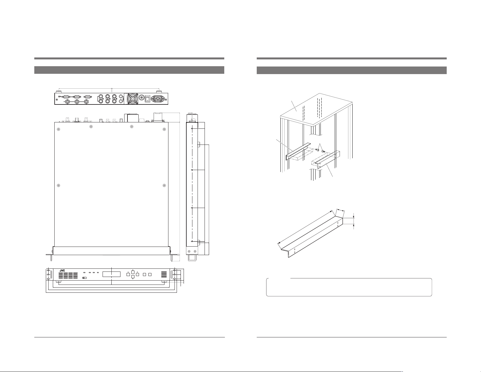
Attaching the L-metal support on EIA rack
L-metal support
EIA rack
L-metal support
Min.420
Screw
L-metal support
M
7
0
Put L-metal supports on the both sides of EIA rack
to secure strength.
in
.
45
20
50
2
23
BC-D2300U
INPUT
STATUS
SYNC
POWER
REMOTE
LOCAL
430±3
465
482
HDTV UP CONVERTER
ENTER
ESC
MENU
195195
1616
43
7
5.5
45
Thickness: 2 mm
WARNING :
● Rack mounting is optional. Use only with racks that have fully adjustable vertical rack rails.
● Use the rack mount brackets (eras) and L-metal supports together.
Do not use only the rack mount brackets (ears) by themselves for support.
Design and specifications subject to change without notice.
21
Page 12

MEMO
MEMO
22
23
 Loading...