

Page 1
AV INTEGRATED AMPLIFIER
AV-INTEGRIERTER VERSTÄRKER
AMPLIFICATEUR INTEGRE AV
GEINTEGREERDE A/V- VERSTERKER
AMPLIFICADOR INTEGRADO DE AV
AMPLIFICATORE INTEGRATO A/V
AX-V55BK
/I
TV
TV VCR AUDIO
/VIDEO
PRESET
SEA MODE
CH+
123
TEST DELAY
SURR MODE
CH– 456
REAR
–+
CD 7/P 8 9
CENTER
–+
CD-DISC
10 +10
TAPE
SEA
SURROUND
AUDIO
TUNER
CONTROL
ON/OFF
ON/OFF
TV CONTROL
VCR TV
VOLUME
–+
ONE TOUCH
VIDEO
OPERATION
PTY SEARCH
DISPLAY
PTY SELECT
–+
PHONO
VOLUME
–+
RM-SAV5RU REMOTE CONTROL
AX-V55 AV INTEGRATED AMPLIFIER
MUTE
STANDBY
POWER
PHONES SPEAKERS
12
_ON —OFF
STANDBY/ON
_ON —OFF
MASTER VOLUME
–+
ENHANCED COMPULINK CONTROL SYSTEM
PRESET SEA SOURCE SURROUND ADJUST
SETTING
ONE TOUCH OPERATION
INSTRUCTIONS
BEDIENUNGSANLEITUNG
MANUEL D’INSTRUCTIONS
GEBRUIKSAANWIJZING
MANUAL DE INSTRUCCIONES
ISTRUZIONI
For Customer Use:
Enter below the Model No. and Serial
No. which are located either on the rear,
bottom or side of the cabinet. Retain this
information for future reference.
Model No.
Serial No.
LVT0236-001A
[E]
Page 2

Table of Contents
English
Switches, Buttons and Controls................................................................................................ 2
Getting Started........................................................................................................................... 3
Before Installation.................................................................................................................... 3
Checking the Supplied Accessories ......................................................................................... 3
Connecting the Speakers .......................................................................................................... 4
Connecting Audio/Video Components .................................................................................... 6
Connecting Audio Components for the COMPU LINK-3 Remote Control System ............... 7
Connecting the Power Cord ..................................................................................................... 8
Putting Batteries in the Remote Control .................................................................................. 8
Basic Operations........................................................................................................................ 9
Turning the Power On and Off (Standby)................................................................................ 9
Selecting the Source to Play..................................................................................................... 9
Selecting the Front Speakers.................................................................................................. 10
Adjusting the Volume ............................................................................................................10
Muting the Sound................................................................................................................... 10
Recording a Source ................................................................................................................ 11
Listening with Headphones.................................................................................................... 11
Basic Settings ........................................................................................................................... 12
Adjusting the Front Speaker Output Balance ........................................................................ 12
Listening at Low Volume (Loudness) ................................................................................... 12
Using the Sleep Timer............................................................................................................ 12
Selecting the Center Speaker Size ......................................................................................... 13
One Touch Operation.............................................................................................................. 14
About the One Touch Operation ............................................................................................ 14
Using the One Touch Operation ............................................................................................ 14
Using the Preset SEA Modes .................................................................................................. 15
Selecting Your Favorite SEA Mode ...................................................................................... 15
Using the Surround Processor................................................................................................ 17
Using JVC’s Hall Surround ................................................................................................... 17
Speaker Arrangements for Dolby Surround........................................................................... 19
Preparing for Dolby Surround................................................................................................ 20
Using Dolby Surround ........................................................................................................... 23
COMPU LINK Remote Control System ............................................................................... 24
Using the Remote Control....................................................................................................... 25
Troubleshooting....................................................................................................................... 27
Specifications............................................................................................................................ 28
Page 1
Page 3

Switches, Buttons and Controls
Become familiar with the buttons and controls on the amplifier before use.
English
21
AX-V55 AV INTEGRATED AMPLIFIER
STANDBY
STANDBY/ON
9p e r
POWER
_ON —OFF
PHONES SPEAKERS
12
_ON —OFF
wq
ENHANCED COMPULINK CONTROL SYSTEM
3
MASTER VOLUME
–+
567
4
PRESET SEA SOURCE SURROUND ADJUST
8
SETTING
ONE TOUCH OPERATION
Refer to the pages in parentheses for details.
t
y
u
i
o
;
TV
/VIDEO
CH+
CH– 456
CD 7/P 8 9
TAPE
TUNER
VCR TV
VIDEO
PHONO
/I
TV VCR AUDIO
PRESET
SEA MODE
123
TEST DELAY
CD-DISC
CONTROL
PTY SEARCH
–+
SURR MODE
REAR
–+
CENTER
–+
10 +10
SEA
SURROUND
AUDIO
ON/OFF
ON/OFF
TV CONTROL
VOLUME
–+
ONE TOUCH
OPERATION
DISPLAY
PTY SELECT
–+
VOLUME
MUTE
RM-SAV5RU REMOTE CONTROL
a
s
d
f
g
h
j
k
Front Panel
1 Remote sensor
2 Display (9)
3 MASTER VOLUME control (10)
4 PRESET SEA button and lamp (15)
5 SOURCE button and lamp (9)
6 SURROUND button and lamp
(17, 20, 23)
7 ADJUST button and lamp (18, 20)
8 SETTING button and lamp (12)
9 STANDBY/ON
button and
STANDBY lamp (9)
p POWER switch (8)
q PHONES jack (11)
w SPEAKERS 1/2 buttons (10)
e Control % / fi / @ / # buttons
r ONE TOUCH OPERATION button
and lamp (14)
Remote Control
t TV/VIDEO button (26)
y CH (+/–) buttons (26)
u CD-DISC button (25)
i AUDIO CONTROL button
(16, 18, 22, 23)
o Source buttons (CD, TAPE,
TUNER, VCR, VIDEO,
PHONO) (9, 25, 26)
; VOLUME (+/–) buttons (10)
a
(Standby/On) buttons (TV,
VCR, AUDIO) (9, 26)
s 10 keys/Audio control buttons
(16, 18, 22, 23, 25)
d SEA ON/OFF button (16)
f SURROUND ON/OFF button
(18, 22, 23)
g TV CONTROL buttons (TV,
VOLUME (+/–)) (26)
h ONE TOUCH OPERATION
button (14)
j Operating buttons for JVC audio/
video components (25, 26)
k MUTE button (10)
Page 2
Page 4

Getting Started
English
Before Installation
Checking the Supplied Accessories
This section explains how to connect stereo components and speakers to the amplifier, and how to connect
the power supply.
General
• Be sure your hands are dry.
• Turn the power off to all components.
• Read the manuals supplied with the components you are going to connect.
Locations
• Install the amplifier in a location that is level and protected from moisture.
• The temperature around the amplifier must be between –5˚ and 35˚ C (23˚ and 95˚ F).
• Make sure there is good ventilation around the amplifier. Poor ventilation could cause overheating and
damage the amplifier.
Handling the amplifier
• Do not insert any metal object into the amplifier.
• Do not disassemble the amplifier or remove screws, covers, or cabinet.
• Do not expose the amplifier to rain or moisture.
Check to be sure you have all of the following items, which are supplied with the amplifier.
The number in the parentheses indicates quantity of the pieces supplied.
• Remote Control (1)
• Batteries (2)
If anything is missing, contact your dealer immediately.
Page 3
Page 5

Connecting the Speakers
Connecting the front speakers
You can connect the following speakers:
• Two sets of front speakers to produce normal stereo sound
• One set of rear speakers to enjoy the surround effect
• One center speaker to produce more effective surround effect (to make human voices outstanding)
• One subwoofer to enhance the bass
For each speaker (except for subwoofer), connect one end of the speaker signal cable (not supplied) to the
speaker terminal on the rear panel and the other end to the speaker. (For connecting a subwoofer, see page 6).
1. Open each terminal.
2. Insert the end of the speaker signal cable as shown (be sure to remove the insulation at the end
of each wire first).
3. Close the terminals to clamp the speaker signal cables firmly in place.
4. Connect the black (–) and red (+) terminals on the rear panel to the black (–) and red (+)
terminals marked on the speakers.
CAUTION:
When connecting speakers, use speakers with the same SPEAKER IMPEDANCE indicated by
the speaker terminals.
Connect the front speakers to the FRONT SPEAKERS terminals.
English
Left Speaker
Connecting the rear and center speakers
Connect rear speakers to the REAR SPEAKERS terminals and a center speaker to the CENTER SPEAKER
terminals.
Center Speaker
SPEAKERS 1
SPEAKERS 2
Right Speaker
CENTER
SPEAKER
RIGHT LEFT
FRONT SPEAKERS
RIGHT LEFT
1
2
REAR
SPEAKERS
1
2
Left Rear
Speaker
Right Rear
Speaker
Note:
When you connect rear speakers, make sure that both left and right speakers are connected; otherwise, no
sound will come out of the rear speakers.
Page 4
Page 6

About the speaker impedance of the speakers
English
Notes:
• The required speaker impedance of the front speakers does not differ depending on whether both the
• The required speaker impedance of the front speakers differs depending on whether or not a center and/
CAUTION:
When connecting speakers, use speakers with the same SPEAKER IMPEDANCE indicated by
the speaker terminals.
1
FRONT SPEAKERS
and FRONT SPEAKERS 2 terminals are used or only one of them is used.
or rear speakers are connected at the same time. Since there are four possible speaker connections with
the amplifier, check which one fits your case and use the speaker with the impedance described below.
CASE 1 When you connect only front speakers
Front
Speaker
Front
Speaker
Use front speakers with 4 — 16 ohm impedance.
CASE 3 When you connect front and rear speakers
CASE 2 When you connect front speakers and a center
speaker
Front
Speaker
Front
Speaker
Center Speaker
Use the following speakers;
• Front speakers: 8 — 16 ohm impedance
• Center speaker: 8 — 16 ohm impedance
CASE 4 When you connect front and rear speakers as
well as a center speaker
Front
Speaker
Rear
Speaker
Use the following speakers;
• Front speakers: 8 — 16 ohm impedance
• Rear speakers: 8 — 16 ohm impedance
Page 5
Front
Speaker
Rear
Speaker
Front
Speaker
Center Speaker
Rear
Speaker
Use the following speakers;
• Front speakers: 8 — 16 ohm impedance
• Rear speakers: 8 — 16 ohm impedance
• Center speaker: 8 — 16 ohm impedance
Front
Speaker
Rear
Speaker
Page 7

Connecting the subwoofer speaker
SUBWOOFER
OUT
Connect the input jack of a powered subwoofer to the SUBWOOFER OUT jack on the rear panel, using a cable
with RCA pin plugs.
Powered subwoofer
Connecting Audio/Video Components
You can connect the following components to the amplifier using cables with RCA pin plugs.
Audio Components Video Components
• Turntable • VCR
• CD player • Video disc player
• Cassette deck • TV
• Tuner
English
Audio component connections
If a ground cable is provided
for your turntable, connect
the cable to the screw marked
Turntable
To audio output
Note:
Any turntables incorporating a small-output cartridge such as an MC (moving-coil type) must be connected
to the amplifier through a commercial head amplifier or step-up transformer. Direct connection may result
in insufficient volume.
on the rear panel.
To audio output
PHONO
TUNER
CD
VIDEO
TAPE
OUT
(REC)IN(PLAY)
OUT
(REC)
(PLAY)
VCR
OUT
(REC)IN(PLAY)
MONITOR
OUT
IN
VIDEO
To audio input
To audio
LEFT
output
AUDIO
RIGHT
CD player
Cassette deck
To audio output
Tuner
Page 6
Page 8

Video component connections
English
MONITOR
OUT
LEFT
AUDIO
RIGHT
TV
To video input
TUNER
CD
VIDEO
TAPEPHONO
OUT
(REC)IN(PLAY)
OUT
(PLAY)
(REC)
VCR
OUT
(REC)IN(PLAY)
IN
VIDEO
To audio/video input
VHS
VCR
To audio/video output
To audio/video output
Video disc player
CAUTION:
If you connect a sound-increasing device such as a graphic equalizer between the source components and the amplifier, the
sound output through the amplifier may be distorted.
Connecting Audio Components for the COMPU LINK-3 Remote Control System
The COMPU LINK-3 remote control system allows you to control other JVC audio components from the
amplifier or vice versa. To use this system, connect your JVC audio components and the amplifier with the
cable (monaural mini-plug) supplied with those components.
If your audio component has two COMPU LINK-3 SYNCHRO jacks, you can use either one.
If it has only one COMPU LINK-3 SYNCHRO jack, connect it so that it is the last item in the series of
components. (for example, the turntable and the tuner in the diagram below)
Notes:
• The COMPU LINK-3 remote control system is the upgraded version of the COMPU LINK-1 and COMPU
LINK-2. Even if your component has the COMPU LINK-1 or COMPU LINK-2 jacks, you can still connect
it in the COMPU LINK-3 remote control system, but some functions may not work correctly.
• For more information about the COMPU LINK-3 (-1 and -2) remote control system, see page 24.
Tuner
CD player
Cassette deck
COMPU LINK – 3
SYNCHRO
Turntable
Page 7
Page 9

Connecting the Power Cord
POWER
ON —OFF
_
Before plugging the amplifier into an AC outlet, make sure that all connections have been made.
1. Plug the power cord into an AC outlet.
2. Press POWER to set it in the
__
_ON position.
__
The STANDBY lamp lights up. A small amount of power is always consumed.
To shut off the power completely:
Press POWER to set it in the —OFF position.
Keep the power cord away from the connecting cables for the TV, VCR, and antenna. The power cord may
cause noise or screen interference.
The difference between the POWER switch and the STANDBY/ON
button
• The POWER switch is the mains supply switch, allowing the amplifier to connect to the mains supply.
To shut off the power completely, press the POWER switch to set it in the —OFF position.
• The STANDBY/ON
button is a functional on/off (standby) switch, and does not disconnect the
amplifier from the mains supply. A small amount of power is consumed even in standby mode for the
amplifier to accept signals from the remote control.
Notes:
The preset settings such as sound adjustment may be erased in the following cases:
—
• When you press POWER to set it in the
OFF position.
• When you unplug the power cord.
• When a power failure occurs.
English
CAUTIONS:
• Do not touch the power cord with wet hands.
• Do not pull on the power cord to unplug the amplifier. When unplugging the amplifier, always
grasp the plug itself so as not to damage the cord.
Putting Batteries in the Remote Control
Before using the remote control, put the two supplied batteries in first. When using the remote control, aim
the remote control directly at the remote sensor on the amplifier.
1. On the back of the remote control, press down on the battery cover and slide it out.
2. Insert batteries. Make sure to observe the proper polarity: (+) to (+) and (–) to (–).
3. Slide the cover.
R6P (SUM-3)/AA (15F)
If the range or effectiveness of the remote control decreases, replace the batteries. Use two R6P (SUM-3)/
AA (15F) type dry-cell batteries.
CAUTIONS:
Follow these precautions to avoid leaking or cracking cells:
• Place batteries in the remote control so they match the polarity indicated: (+) to (+) and (–)
to (–).
• Use the correct type of batteries. Batteries that look similar may differ in voltage.
• Always replace both batteries at the same time.
• Do not expose batteries to heat or flame.
Page 8
Page 10

Basic Operations
English
Turning the Power On and Off (Standby)
STANDBY
The following operations are commonly used when you play any sound source.
On the front panel:
To turn on the power, press STANDBY/ON
.
The STANDBY lamp goes off. The name of the current source appears on the display.
STANDBY/ON
STANDBY
STANDBY/ON
AUDIO
Selecting the Source to Play
SLEEP SEA
PRO LOGIC 3CH LOGIC HALL LOUDNESS
Current source name appears
L
VOLUME
Current volume level is shown here
To turn off the power (into standby mode), press STANDBY/ON
R
again.
The STANDBY lamp lights up.
From the remote control:
To turn on the power, press AUDIO.
The STANDBY lamp goes off. The name of the current source appears on the display.
To turn off the power (into standby mode), press AUDIO again.
The STANDBY lamp lights up.
Note:
Pressing STANDBY/ON
again turns off the power (into standby mode) and lights the STANDBY lamp.
A small amount of power is consumed in standby mode. To turn the power off completely, press POWER to
set it in the —OFF position on the front panel.
SOURCE
CD
TAPE
TUNER
VCR
VIDEO
PHONO
On the front panel:
%%
1. Press SOURCE so that Control
fifi
% /
fi buttons work for selecting the source.
%%
fifi
The lamp above the button lights up.
%%
2. Press Control
fifi
% /
fi until the source name you want appears on the display.
%%
fifi
VOLUME
From the remote control:
Press one of the source button directly.
CD* Listen to the CD player.
TAPE* Listen to the cassette deck connected to the TAPE jacks.
TUNER* Listen to the radio.
VCR View the video component connected to the VCR jacks.
VIDEO View the video component connected to the VIDEO jacks.
PHONO* Listen to a record.
Note:
* When you press one of the source buttons on the remote control marked above with an asterisk, the amplifier
automatically turns on.
Page 9
Page 11

Selecting different sources for picture and sound
You can watch picture from video equipment while listening to sound from audio equipment.
To listen to the sound from audio equipment while watching the picture from video equipment:
1. Select the video equipment as the source (VIDEO or VCR).
2. Press one of the source buttons for the audio equipment (TUNER, TAPE, PHONO or CD) on
the remote control.
Selecting the Front Speakers
When you have connected two sets of front speakers, you can select which to use. Pressing SPEAKERS 1 or
SPEAKERS 2 activates the respective set of speakers.
English
SPEAKERS
12
_ON —OFF
Adjusting the Volume
MASTER VOLUME
–+
On the front panel
VOLUME
–+
From the remote control
To use the set of speakers connected to the FRONT SPEAKERS 1 terminals, press SPEAKERS 1 to set
it in the _ON position, and press SPEAKERS 2 to set it in the —OFF position.
To use the set of speakers connected to the FRONT SPEAKERS 2 terminals, press SPEAKERS 2 to set
it in the _ON position, and press SPEAKERS 1 to set it in the —OFF position.
To use both sets of speakers, press both SPEAKERS 1 and 2 to set them in the _ON position.
To use neither set of speakers, press both SPEAKERS 1 and 2 to set them in the —OFF position.
Note:
When only one set of the front speakers is connected to either the FRONT SPEAKERS
not press both SPEAKERS 1 and 2 to set them in the
_
ON position. If you do, no sound comes out of the front
1
or 2 terminals, do
speakers.
On the front panel:
To increase the volume, turn MASTER VOLUME clockwise.
To decrease the volume, turn it counterclockwise.
When you turn MASTER VOLUME rapidly, the volume level also changes rapidly.
When you turn MASTER VOLUME slowly, the volume level also changes slowly.
From the remote control:
To increase the volume, press VOLUME +.
To decrease the volume, press VOLUME –.
CAUTION:
Always set the volume to the minimum before starting any source. If the volume is set at its high
level, the sudden blast of sound energy can permanently damage your hearing and/or ruin your
speakers.
Muting the Sound
MUTE
From the remote control only:
Press MUTE to mute the sound through all speakers and headphones connected.
“MUTE” appears on the display and the volume turns off.
To restore the sound, press MUTE again so that “OFF” appears on the display.
Turn MASTER VOLUME or pressing VOLUME +/– also restores the sound at the previous volume level.
Page 10
Page 12

Recording a Source
English
Listening with Headphones
SPEAKERS
12
_ON —OFF
You can record any source playing through the amplifier to a cassette deck connected to the TAPE jacks
and VCR connected to the VCR jacks at the same time.
While recording, you can listen to the selected sound source at whatever sound level you like, without
affecting the sound levels of the recording.
Note:
The output volume level, preset SEA, and surround modes cannot affect the recording.
A standard pair of headphones can be connected to the PHONES jack on the front panel. Be sure to turn down
the volume before connecting or putting on headphones, as high volume can damage both the
headphones and your hearing.
To listen with only headphones
Press both SPEAKERS 1 and 2 to set them in the —OFF position.
Page 11
Page 13

Basic Settings
Some of the following settings are required after connecting and positioning your speakers in your listening
room, while others will make operations easier.
Adjusting the Front Speaker Output Balance
SETTING
If the sounds you hear from the front right and left speakers are unequal, you can adjust the speaker output
balance.
On the front panel only:
1. Press SETTING so that the Control
The lamp above the button lights up.
2. Press Control
3. Press Control
• Pressing Control @ decreases the right channel output.
• Pressing Control # decreases the left channel output.
Listening at Low Volume (Loudness)
%%
fifi
@@
% /
%%
%%
fifi
% /
fi until “BALANCE” appears on the display.
%%
fifi
@@
##
@ /
# to adjust the balance.
@@
##
##
fi /
@ /
# buttons work for adjusting the balance.
fifi
@@
##
English
SETTING
Using the Sleep Timer
SETTING
Human ears are not sensitive to bass at low volume. To compensate for this, the loudness function
automatically boosts the bass level as you lower the volume.
On the front panel only:
%%
fifi
@@
1. Press SETTING so that the Control
% /
%%
##
fi /
@ /
# buttons work for setting the loudness.
fifi
@@
##
The lamp above the button lights up.
%%
2. Press Control
3. Press Control
fifi
% /
fi until “LOUDNESS” appears on the display.
%%
fifi
@@
##
@ /
# to set the loudness function to “ON” or “OFF.”
@@
##
• Select “ON” to activate the loudness function.
The LOUDNESS indicator lights up on the display.
• Select “OFF” to cancel it.
The indicator goes off.
Using the Sleep Timer, you can fall asleep to music and know the amplifier will turn off by itself rather than
play all night.
On the front panel only:
%%
fifi
@@
1. Press SETTING so that the Control
% /
%%
##
fi /
@ /
# buttons work for setting the Sleep Timer.
fifi
@@
##
The lamp above the button lights up.
%%
2. Press Control
3. Press Control
fifi
% /
fi until “<SLEEP>” appears on the display.
%%
fifi
@@
##
@ /
# to set the shut-off time.
@@
##
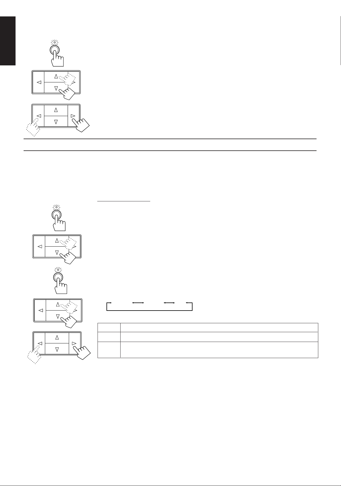
Each time you press the button, the shut-off time on the display changes as follows, and the SLEEP
indicator lights up on the display.
2010 30 40 50 60 70 80
0
(Canceled)
Continue to the next page
Page 12
Page 14
When the shut-off time comes, the amplifier turns off (into standby mode) automatically.
SETTING
English
Selecting the Center Speaker Size
SURROUND
To check or change the time remaining until the shut-off time:
1. Press SETTING if necessary, so that the Control % / fi / @ / # buttons work for setting the Sleep Timer.
2. Press Control % / fi if necessary, until “<SLEEP>” appears on the display.
3. Press Control @ / #.
The remaining time until the shut-off time appears in minutes.
• To change the shut-off time, press Control @ / # repeatedly.
To cancel the Sleep Timer, press Control @ / # repeatedly in step 3 above until “0” appears on the display.
(The SLEEP indicator goes off.)
Turning off the power (into standby mode) also cancels the Sleep Timer.
You can register the information about the center speaker after all connections are completed.
If you do this registration first, you do not have to adjust the center speaker mode when you want to activate
the surround sound.
However, to register the information, first you have to set the surround mode either to “PROLOGIC” or
“3CHLOGIC.” (You cannot select the center speaker size when the surround mode is “OFF” or “HALL.”)
On the front panel only:
%%
1. Press SURROUND so that the Control
fifi
% /
fi buttons work for selecting the surround mode.
%%
fifi
The lamp above the button lights up.
SETTING
%%
2. Press Control
fifi
% /
fi until “PROLOGIC” or “3CHLOGIC” appears on the display.
%%
fifi
The indicator of the selected mode also lights up on the display.
%%
fifi
@@
3. Press SETTING so that the Control
% /
%%
##
fi /
@ /
# buttons work for selecting the center speaker
fifi
@@
##
size.
The lamp above the button lights up.
%%
4. Press Control
5. Press Control
fifi
% /
fi until “CNTR SPK” (Center Speaker) appears on the display.
%%
fifi
@@
##
@ /
# to select the appropriate item about your center speaker.
@@
##
Each time you press the button, the display changes to show the following:
LARGE SMALL
NO
LARGE Select this mode when the size of the center speaker is the same as that of the front speakers.
SMALL Select this mode when the size of the center speaker is smaller than that of the front speakers.
NO Select this mode when you do not use a center speaker.
(This mode cannot be selected when you select “3CHLOGIC.”)
Note:
This “center speaker size” setting is so related to the center mode setting for the Dolby Surround that
changing this setting affects and changes the center mode to a relevant mode, and vice versa.
For example;
• If you select “LARGE,” the center mode is automatically set to “WIDE,” and vice versa.
• If you select “SMALL,” the center mode is automatically set to “NORMAL,” and vice versa.
• If you select “NO,” the center mode is automatically set to “PHANTOM” for PRO LOGIC, and vice versa.
Page 13
Page 15

One Touch Operation
This amplifier can memorize the optimum sound setting for each playing source.
About the One Touch Operation
JVC’s One Touch Operation function is used to assign and store different sound settings for each different
playing source. By using this function, you do not have to change the settings every time you change the
source. The stored settings for the newly selected source are automatically recalled.
The following can be stored for each source:
• Volume level (see page 10)
• Balance (see page 12)
• Loudness (see page 12)
• Preset SEA modes (see page 15)
• Surround mode settings (see page 17)
Using the One Touch Operation
To store the sound settings:
1. Press ONE TOUCH OPERATION.
ONE TOUCH
ONE TOUCH OPERATION
On the front
panel
OPERATION
From the
remote control
2. Adjust the sound using the functions listed above.
To recall the sound settings:
With the ONE TOUCH OPERATION lamp lit, the settings for the currently selected source is recalled, and
appears on the display when the source is selected.
English
The ONE TOUCH OPERATION lamp lights up, then the previously memorized settings are recalled
and appear on the display in turn.
The newly adjusted settings are memorized.
To cancel the One Touch Operation function:
Press ONE TOUCH OPERATION so that the lamp goes off. (Even though the One Touch Operation function
is canceled, the recalled sound effects remain active.)
Page 14
Page 16

Using the Preset SEA Modes
English
Selecting Your Favorite SEA Mode
PRESET SEA
The preset SEA (Sound Effect Amplifier) modes give you control over the way your music sounds.
Note:
The preset SEA mode cannot be used for recording.
On the front panel:
%%
fifi
@@
1. Press PRESET SEA so that the Control
% /
%%
##
fi /
@ /
# buttons work for preset SEA setting.
fifi
@@
##
The lamp above the button lights up.
%%
2. Press Control
fifi
% /
fi until the mode you want appears on the display.
%%
fifi
The SEA indicator also lights up on the display.
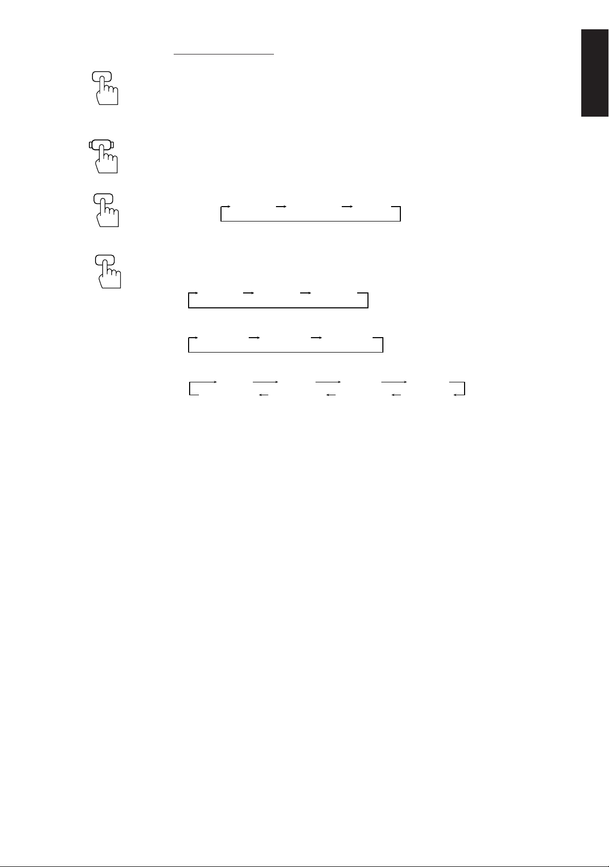
Each time you press the button, the preset SEA modes change as follows:
MOVIE SPORTS MUSIC
OFF
Note:
When you turn on the preset SEA mode, the mode and its effect level previously selected is recalled at first.
@@
3. Press Control
##
@ /
# to select the effect level.
@@
##
Each time you press the button, the effect level changes as follows:
When “MOVIE” is selected:
MOVIE 1 MOVIE 2 MOVIE 3
When “SPORTS” is selected:
SPORTS1 SPORTS2 SPORTS3
When “MUSIC” is selected:
JAZZ 1 JAZZ 2
COUNTRY2 COUNTRY1 MUSICAL2 MUSICAL1
ROCK 1 ROCK 2
MOVIE Adds breadth to sounds so you feel like you are in a movie theater.
SPORTS Makes sound exciting.
MUSIC Select one of the modes below:
JAZZ: Gives a feeling of a live atmosphere. Good for acoustic music.
ROCK: Gives a heavy sound. Both high and low frequencies are boosted.
MUSICAL: Enhances the mid-frequency range, which the human voice is mostly
made up of.
COUNTRY: Enhance the high-frequency range so that instruments such the violin
and banjo are emphasized.
OFF No preset SEA mode is applied. (See below)
To cancel the preset SEA mode, select “OFF” in step 2 above.
The SEA indicator goes off from the display.
Page 15
Page 17
SEA
ON/OFF
AUDIO
CONTROL
From the remote control:
1. Press SEA ON/OFF so that the SEA indicator lights up on the display.
The previously selected mode is recalled (at its previous effect level) and is shown on the display.
Each time you press the button, the preset SEA mode turns on and off.
Note:
When selecting the preset SEA mode, the display will show the current effect level of the preset SEA mode
selected.
2. Press AUDIO CONTROL so that 10 keys work for adjusting the sound.
English
SEA MODE
3
PRESET
2
3. Press SEA MODE until the mode you want appears on the display.
Each time you press the button, the three preset SEA modes change as follows:
Ex.
MOVIE 1 SPORTS2 JAZZ 2
4. Press PRESET to select the effect level.
Each time you press the button, the effect level changes as follows:
When “MOVIE” is selected:
MOVIE 1 MOVIE 2 MOVIE 3
When “SPORTS” is selected:
SPORTS1 SPORTS2 SPORTS3
When “MUSIC” is selected:
JAZZ 1 JAZZ 2
COUNTRY2 COUNTRY1 MUSICAL2 MUSICAL1
ROCK 1 ROCK 2
To cancel the preset SEA mode, press SEA ON/OFF so that the SEA indicator goes off from the
display.
Each time you press the button, the preset SEA mode turns on and off.
Page 16
Page 18

Using the Surround Processor
DOLBY SURROUND
English
What is surround?
The built-in surround processor provides three types of surround programs — Dolby Pro Logic, Dolby 3Channel Logic, and JVC’s Hall Surround.
The sound heard in a concert hall or a movie theater consists of direct sound and indirect sound: early
reflections and reflections from behind. The reflected sounds are always delayed by the distances of the ceiling
and walls from the listener. These reflections are some of the most important elements of the acoustic
surround.
On JVC’s Hall Surround
In order to reproduce a more realistic sound field in your listening
room while playing an ordinary stereo source, JVC’s Hall Surround
has been designed to give you clear vocals and to create the
feeling of a concert hall. The sound is reproduced through the
front speakers and rear speakers.
On Dolby Surround
Dolby Surround has been also developed to reproduce the
important elements of the acoustic surround at home.
To watch the soundtracks of video software bearing the mark
* which includes the same encoded surround
information as found in Dolby Stereo films, the amplifier can
provide you with 2 Dolby Surround programs (Dolby Pro Logic
and Dolby 3ch Logic).
Dolby Pro Logic: Select this mode when the optional rear
speakers are connected (as well as a center speaker).
Dolby 3ch Logic: Select this mode when a center speaker is
connected without rear speakers.
* Manufactured under license from Dolby Laboratories Licensing
Corporation. “Dolby,” the double-D symbol, and “Pro Logic” are
trademarks of Dolby Laboratories Licensing Corporation.
Using JVC’s Hall Surround
You need to connect one set of rear speakers to obtain the full effect.
Once you have adjusted the Hall Surround, the amplifier memorizes the settings.
On the front panel:
SURROUND
1. Press SURROUND so that the Control
modes.
The lamp above the button lights up.
%%
2. Press Control
The HALL indicator also lights up on the display.
Each time you press the button, the surround modes change as follows:
PROLOGIC
fifi
% /
fi until “HALL” appears on the display.
%%
fifi
3CHLOGIC
OFF
The indicator of the selected surround mode lights up in turn as you select the surround modes.
Notes:
• The surround processor has no effect on monaural sources.
• The surround processor cannot be used for recording.
%%
fifi
@@
% /
%%
##
fi /
@ /
# buttons work for selecting the surround
fifi
@@
##
HALL
Page 17
Page 19

ADJUST
3. Press ADJUST so that the Control
The lamp above the button lights up.
%%
% /
%%
fifi
@@
##
fi /
@ /
# buttons work for surround settings.
fifi
@@
##
%%
4. Press Control
5. Press Control
fifi
% /
fi until “– REAR +” appears on the display.
%%
fifi
@@
##
@ /
# to adjust the rear speaker output level.
@@
##
• Pressing Control @ decreases the output level up to –10 dB.
• Pressing Control # increases the output level up to +10 dB.
%%
6. Press Control
7. Press Control
fifi
% /
fi until “–DELAY +” appears on the display.
%%
fifi
@@
##
@ /
# to adjust the delay time of the rear speaker output.
@@
##
Each time you press the button, the delay time changes as follows:
DELAY 1 DELAY 2 DELAY 3
DELAY 1 Select this when the distance from you to your rear speakers is greater than that to the front
speakers.
DELAY 2 Select this when the distance from you to your rear speakers is almost equal to that to the
front speakers.
DELAY 3 Select this when the distance from you to your rear speakers is less than that to the front
speakers.
To cancel the Hall surround, select “OFF” in step 2. The HALL indicator goes off.
English
SURROUND
ON/OFF
AUDIO
CONTROL
SURR MODE
6
REAR
–+
89
DELAY
5
From the remote control:
1. Press SURROUND ON/OFF so that one of the surround mode indicators (PRO LOGIC, 3CH
LOGIC, HALL) lights up on the display.
The previous mode is recalled (at its previous settings) and is shown on the display.
Each time you press the button, the surround mode turns on and off.
2. Press AUDIO CONTROL so that 10 keys work for adjusting the sound.
3. Press SURR MODE until “HALL” appears on the display.
The HALL indicator also lights up on the display.
Each time you press the button, the surround modes change as follows:
PROLOGIC
3CHLOGIC
HALL
The indicator of the selected surround mode lights up in turn as you select the surround modes.
4. Press REAR +/– to adjust the rear speaker output level.
• Pressing REAR – decreases the output level up to –10 dB.
• Pressing REAR + increases the output level up to +10 dB.
5. Press DELAY to adjust the delay time.
Each time you press the button, the delay time changes as follows:
DELAY 1 DELAY 2 DELAY 3
To cancel the Hall Surround, press SURROUND ON/OFF so that the HALL indicator goes off.
Each time you press the button, the surround mode turns on and off.
Page 18
Page 20

Speaker Arrangements for Dolby Surround
English
The following illustrations show how to obtain the optimum sound environment for various Dolby Surround
settings. Try to find the speaker direction and location to create the optimum sound field.
CASE 1 When you have added a center speaker and rear speakers
Front
Speaker
TV
Front
Speaker
Center Speaker
Rear
Speaker
Rear
Speaker
CASE 2 When you have added rear speakers (without a center speaker)
In this case:
1. Select “PROLOGIC.”
2. Select “NORMAL” or “WIDE” for center mode.
See pages 20 to 22 for more details.
Front
Speaker
Rear
Speaker
TV
Front
Speaker
Rear
Speaker
CASE 3 When you have added a center speaker (without rear speakers)
Front
Speaker
TV
Front
Speaker
Center Speaker
In this case:
1. Select “PROLOGIC.”
2. Select “PHANTOM” for center mode.
See pages 20 to 22 for more details.
Page 19
In this case:
1. Select “3CHLOGIC.”
2. Select “NORMAL” or “WIDE” for center mode.
See pages 20 to 22 for more details.
Page 21

Preparing for Dolby Surround
SURROUND
ADJUST
The amplifier memorizes two sets of Dolby Surround adjustments; one for Pro Logic and the other for 3ch
Logic.
On the front panel:
%%
1. Press SURROUND so that the Control
The lamp above the button lights up.
%%
2. Press Control
display.
The PRO LOGIC or 3CH LOGIC indicator also lights up.
Each time you press the button, the surround modes change as follows:
PROLOGIC
fifi
% /
fi until “PROLOGIC” or “3CHLOGIC” whichever you want appears on the
%%
fifi
3CHLOGIC
fifi
% /
fi buttons work for selecting the surround modes.
%%
fifi
HALL
OFF
The indicator of the selected surround mode lights up in turn as you select the surround modes.
PROLOGIC Select this mode when you use a center speaker and rear speakers.
3CHLOGIC Select this mode when you use a center speaker without rear speakers.
HALL This is JVC’s original surround mode, and is different from Dolby Surround. To use
this, see page 17.
OFF Select this to turn off the surround mode.
%%
fifi
@@
3. Press ADJUST so that the Control
surround mode.
The lamp above the button lights up.
% /
%%
##
fi /
@ /
# buttons work for adjusting the selected
fifi
@@
##
English
%%
4. Press Control
5. Press Control
Each time you press the button, the center modes change as follows:
WIDE
fifi
% /
fi until “CNT MODE” (Center Mode) appears on the display.
%%
fifi
@@
##
@ /
# to select the center mode.
@@
##
NORMAL
PHANTOM
OFF
WIDE Select this mode when the center speaker can reproduce the bass better than the front
speakers. All signals of the center channel are output through the center speaker.
NORMAL Select this mode when the center speaker cannot reproduce the bass better than the
front speakers. The bass portions of the center channel signals are output through the
front speakers.
PHANTOM Select this mode when you do not use a center speaker. The center speaker channel
signals are output through the front speakers.
OFF Select this mode to turn off the center speaker channel.
Notes:
• If you have already set the center speaker size following the procedure described on page 13, you do
not have to select the center mode in this procedure.
• When you have selected “3CHLOGIC,” you cannot select “PHANTOM.”
Continue to the next page
Page 20
Page 22

English
%%
6. Press Control
7. Press Control
Each time you press the button, the delay time changes as follows:
fifi
% /
fi until “–DELAY +” appears on the display.
%%
fifi
@@
##
@ /
# to adjust the delay time of the rear speaker output.
@@
##
DELAY 1 DELAY 2 DELAY 3
DELAY 1 Select this when the distance from you to your rear speakers is greater than that to the
front speakers.
DELAY 2 Select this when the distance from you to your rear speakers is almost equal to that to
the front speakers.
DELAY 3 Select this when the distance from you to your rear speakers is less than that to the front
speakers.
Note:
When you have selected “3CHLOGIC,” you cannot adjust the delay time.
%%
8. Press Control
checking the speaker output balance.
“TEST” starts flashing on the display, and a test tone comes out of the speakers in the following
order:
Left front
speaker
fifi
% /
fi until “TEST” appears on the display, then press Control
%%
fifi
Center
speaker
Right front
speaker
@@
@ /
@@
##
# to start
##
Rear
speakers
Notes:
• No test tone comes out of the rear speakers when you have selected “3CHLOGIC.”
• No test tone comes out of the center speaker when you select “PHANTOM” or “OFF” for the center
mode.
9. If necessary, adjust the speaker output balance as follows:
• To adjust the rear speaker output level, press Control % / fi until “– REAR +” appears on the
display, then press Control @ / #.
• To adjust the center speaker output level, press Control % / fi until “–CENTER+” appears on the
display, then press Control @ / #.
Notes:
• The sound levels of the left and right rear speakers will be the same.
• You cannot set the sound level of the rear speakers when you have selected “3CHLOGIC.”
• You cannot set the sound level of the center speaker when you select “PHANTOM” or “OFF” for the
center mode.
%%
10. Press Control
test tone.
fifi
% /
fi until “TEST” appears on the display, then press Control
%%
fifi
@@
##
@ /
# to stop the
@@
##
Page 21
Page 23

From the remote control:
If you have already set the center speaker size following the procedure described on page 13, you can use the
remote control for Dolby Surround preparation.
SURROUND
ON/OFF
AUDIO
CONTROL
SURR MODE
6
DELAY
5
TEST
4
1. Press SURROUND ON/OFF so that one of the surround mode indicators (PRO LOGIC, 3CH
LOGIC, HALL) lights up on the display.
The previous mode is recalled (at its previous settings) and is shown on the display.
Each time you press the button, the surround mode turns on and off.
2. Press AUDIO CONTROL so that 10 keys work for adjusting the sound.
3. Press SURR MODE until “PROLOGIC” or “3CHLOGIC” whichever you want appears on the
display.
Each time you press the button, the surround modes change as follows:
PROLOGIC
3CHLOGIC
HALL
The indicator of the selected surround mode lights up in turn as you select the surround modes.
4. Press DELAY to adjust the delay time of the rear speaker output.
Each time you press the button, the delay time changes as follows:
DELAY 1 DELAY 2 DELAY 3
Note:
When you have selected “3CHLOGIC,” you cannot adjust the delay time.
5. Press TEST to start checking the speaker output balance.
“TEST” starts flashing on the display, and a test tone comes out of the speakers in the following
order:
Left front
speaker
Center
speaker
Right front
speaker
Rear
speakers
Notes:
• No test tone comes out of the rear speakers when you have selected “3CHLOGIC.”
• No test tone comes out of the center speaker when you select “PHANTOM” or “OFF” for the center
mode.
English
REAR
–+
89
CENTER
–+
10 +10
TEST
4
6. If necessary, adjust the speaker output balance as follows:
• To adjust the rear speaker output level, press REAR+/–.
• To adjust the center speaker output level, press CENTER +/–.
Pressing – decreases the output level up to –10 dB.
Pressing + increases the output level up to +10 dB.
Notes:
• The sound levels of the left and right rear speakers will be the same.
• You cannot set the sound level of the rear speakers when you have selected “3CHLOGIC.”
• You cannot set the sound level of the center speaker when you select “PHANTOM” or “OFF” for the
center mode.
7. Press TEST again to stop the test tone.
Page 22
Page 24

Using Dolby Surround
English
SURROUND
SURROUND
ON/OFF
AUDIO
CONTROL
Once you have set the Dolby Surround adjustments, you can use the same adjustments every time you want
to enjoy Dolby Surround.
On the front panel:
%%
1. Press SURROUND so that the Control
fifi
% /
fi buttons work for selecting the surround modes.
%%
fifi
The lamp above the button lights up.
%%
2. Press Control
fifi
% /
fi until “PROLOGIC” or “3CHLOGIC” whichever you want appears on the
%%
fifi
display.
The PRO LOGIC or 3CH LOGIC indicator also lights up.
Each time you press the button, the surround modes change as follows:
PROLOGIC
3CHLOGIC
HALL
OFF
The indicator of the selected surround mode lights up in turn as you select the surround modes.
3. Select and play a sound source which was processed with Dolby Surround and is labeled with
DOLBY SURROUND
To cancel Dolby Surround, select “OFF” in step 2 above. The indicator of the selected mode goes off.
From the remote control:
1. Press SURROUND ON/OFF so that one of the surround mode indicators (PRO LOGIC, 3CH
LOGIC, HALL) lights up on the display.
The previous mode is recalled (at its previous settings) and is shown on the display.
Each time you press the button, the surround mode turns on and off.
2. Press AUDIO CONTROL so that 10 keys work for adjusting the sound.
mark.
SURR MODE
6
3. If necessary, press SURR MODE until “PROLOGIC” or “3CHLOGIC” whichever you want
appears on the display.
Each time you press the button, the surround modes change as follows:
PROLOGIC
3CHLOGIC
HALL
The indicator of the selected surround mode lights up in turn as you select the surround modes.
4. Select and play a sound source which was processed with Dolby Surround and is labeled with
DOLBY SURROUND
mark.
To cancel Dolby Surround, press SURROUND ON/OFF so that the indicator of the selected mode goes
off.
Each time you press the button, the surround mode turns on and off.
Page 23
Page 25

COMPU LINK Remote Control System
The COMPU LINK remote control system allows you to operate JVC audio components through the remote
sensor on the amplifier.
To use this remote control system, you need to connect JVC audio components through the COMPU LINK3 SYNCHRO jacks with the cables (monaural mini-plug supplied with those components). For details, see
page 7.
Notes:
• Without connecting the audio components with RCA pin plugs as described on page 6, the COMPU LINK
remote control system cannot operate the components.
• Refer also to the manuals supplied with your audio components.
This remote control system allows you to use the four functions listed below.
77
7 Remote Control through the Remote Sensor on the Amplifier
77
You can control JVC audio components through the remote sensor on the amplifier using this remote control.
Aim the remote control directly at the remote sensor on the amplifier.
For details, see page 25.
77
7 Automatic Source Selection
77
When you start playing on a connected component, the amplifier automatically turns on and changes its source
to the component. On the other hand, if you select a new source on the amplifier or the remote control, the
selected component begins playing immediately.
In both cases, the previously selected source continues playing without sound for a few seconds.
English
77
7 Automatic Power On/Off (Standby) (only possible with the COMPU LINK-3 connection)
77
The audio components (tuner, CD player and cassette deck) connected to the amplifier automatically turn on
and off (into standby mode) with the amplifier.
When you turn on the amplifier, one of the connected components will turn on automatically, depending which
component has been previously selected.
When you turn off the amplifier (into standby mode), these components connected will turn off (into standby
mode).
77
7 Synchronized Recording
77
Synchronized recording means the cassette deck starts recording as soon as a CD or record begins playing.
To use synchronized recording, follow these steps:
1 Put a tape in the cassette deck, and a disc in the CD player (or a record on the turntable).
2 Press the record (¶) button and the pause (8) button on the cassette deck at the same time.
This puts the cassette deck into recording pause.
Note:
If you do not press the record (¶) button and pause (8) button at the same time, the synchronized recording
feature will not operate.
3 Press the play (3) button on the CD player or on the turntable.
The source changes on the amplifier, and as soon as play starts, the cassette deck starts recording.
When the play ends, the cassette deck enters recording pause, and stops 4 seconds later.
Notes:
• During synchronized recording, the selected source cannot be changed.
• If your CD player is playing in program mode, a 4-second blank is recorded between tracks so that the music
scan feature of your cassette deck can be used on the recorded tape.
• If the power of any component is shut off during synchronized recording, the COMPU LINK remote control
system may not operate properly. In this case, you must start again from the beginning.
• Refer also to the manuals supplied with your CD player and cassette deck.
Page 24
Page 26

Using the Remote Control
You can operate JVC audio and video components with the amplifier’s remote control, since control signals for JVC components are preset in
the remote control.
English
To operate these components with the remote control, first select a source with the source buttons on the remote control. Then, operate that source
using the remote control.
IMPORTANT:
To operate JVC audio components using this remote control:
• You need to connect JVC audio components through the COMPU LINK-3 SYNCHRO jacks (see page 7) in addition to the
connections using cables with RCA pin plugs (see page 6).
• Aim the remote control directly at the remote sensor on the amplifier.
After pressing TUNER, you can perform the following operations:
TV
/VIDEO
CH+
CH– 456
CD 7/P 8 9
TAPE
TUNER
VCR TV
VIDEO
PHONO
/I
TV VCR AUDIO
PRESET
SEA MODE
123
TEST DELAY
CD-DISC
AUDIO
CONTROL
PTY SEARCH
–+
–+
RM-SAV5RU REMOTE CONTROL
SURR MODE
REAR
–+
CENTER
–+
10 +10
SEA
SURROUND
ON/OFF
ON/OFF
TV CONTROL
VOLUME
–+
ONE TOUCH
OPERATION
DISPLAY
PTY SELECT
VOLUME
MUTE
1 — 10, +10 Selects a preset channel number directly
For channel number 5, press 5.
For channel number 15, press +10, then 5.
For channel number 20, press +10, then 10.
For channel number 30, press +10, +10 then 10.
RDS operating buttons
PTY SEARCH Starts and ends searching a broadcast using the RDS.
PTY SELECT +/– Selects a program type.
DISPLAY Changes the RDS display mode.
After pressing CD, you can perform the following operations on a CD player:
3 Starts playing
4 Returns to the beginning of the current (or previous) track
¢ Skips to the beginning of the next track
7 Stops playing
8 Pauses. To resume playing, press 3.
1 — 10, +10 Selects a track number directly
For track number 5, press 5.
For track number 15, press +10, then 5.
For track number 20, press +10, then 10.
For track number 30, press +10, +10, then 10
After pressing CD-DISC, you can perform the following operations on a CD player-changer:
1 — 6, 7/P Select the number of a disc installed in a CD player-changer. Then continue to
operate the CD player as described above.
After pressing TAPE, you can perform the following operations on a cassette deck:
3 Starts playback
4 Fast winds a tape from right to left
¢ Fast winds a tape from left to right
7 Stops operation
8 Pauses. To resume playing, press 3.
Page 25
Page 27

IMPORTANT:
To operate JVC video components using this remote control:
• Aim the remote control directly at the remote sensor on the VCR or TV, not on the amplifier.
After pressing VCR, you can perform the following operations on a VCR:
TV
/VIDEO
CH+
CH– 456
CD 7/P 8 9
TAPE
TUNER
VCR TV
VIDEO
PHONO
/I
TV VCR AUDIO
PRESET
SEA MODE
123
TEST DELAY
CD-DISC
CONTROL
PTY SEARCH
–+
–+
SURR MODE
REAR
–+
CENTER
–+
10 +10
SEA
SURROUND
AUDIO
ON/OFF
ON/OFF
TV CONTROL
VOLUME
–+
ONE TOUCH
OPERATION
DISPLAY
PTY SELECT
VOLUME
MUTE
RM-SAV5RU REMOTE CONTROL
3 Starts playback
4 Rewinds a video tape
¢ Fast winds a video tape
7 Stops operation
8 Pauses. To resume playing, press 3.
CH+/– Changes channels on a VCR
Without pressing VCR, you can always perform the following:
VCR (in the
(Standby/On) section)
Turns on/off the VCR
After pressing TV (in the TV CONTROL section), you can perform the following operations on TV:
CH+/– Changes TV channels
Without pressing TV (in the TV CONTROL section), you can always perform the following :
TV/VIDEO Sets input mode (either to TV or to VIDEO)
VOLUME +/– (in the TV CONTROL section)
Adjusts the volume
TV (in the
(Standby/On) section)
Turns on/off the TV
English
Page 26
Page 28

Troubleshooting
English
Use this chart to help you solve daily operational problems. If there is any problem you cannot solve, contact
your JVC service center.
PROBLEM
The display does not light up
No sound from speakers
Sound from one speaker only
Howling during record
playing
Remote control does not
work
POSSIBLE CAUSE
The power cord is not plugged in
or the POWER switch is
to set in the —OFF position
Speaker signal cables are not
connected
The SPEAKERS 1 and 2 are not
set correctly
An incorrect source is selected
Speaker signal cables are not
connected properly
The balance is set to one extreme
Your turntable is too close to
speakers
There is an obstruction in front of
the remote sensor on the
amplifier
pressed
SOLUTION
Plug the power cord into an AC outlet
and press POWER to set it in the _ON
position
Check speaker wiring and
reconnect if necessary
Press SPEAKERS 1 and 2 correctly
Select the correct source
Check speaker wiring and reconnect if
necessary
Adjust the balance properly (see page
12)
Move speakers away from the turntable
Remove the obstruction
Batteries are weak
Replace batteries
Page 27
Page 29

Specifications
Amplifier
Output Power At Stereo Operation
Front Channels 55 watts per channel, min. RMS, driven into 4 ohms at 1 kHz with
no more than 0.9% total harmonic distortion. (IEC268-3/DIN)
40 watts per channel, min. RMS, driven into 8 ohms at 1 kHz with
no more than 0.9% total harmonic distortion. (IEC268-3/DIN)
40 watts per channel, min. RMS, driven into 8 ohms, 40 Hz to 20
kHz with no more than 0.8% total harmonic distortion.
At Surround Operation
Front Channels 50 watts per channel, min. RMS, driven into 8 ohms at 1 kHz with
no more than 0.8% total harmonic distortion.
Center Channel 50 watts, min. RMS, driven into 8 ohms at 1 kHz, with no more
than 0.8% total harmonic distortion.
Rear Channels 50 watts per channel, min. RMS, driven into 8 ohms at 1kHz, with
no more than 0.8% total harmonic distortion.
Total Harmonic Distortion 0.8 %* at 40 watts output
(8 ohms, 1 kHz) (* Measured by JVC Audio Analysis System)
Frequency Response (8 ohms) PHONO 20 Hz to 20 kHz (±1 dB)
TUNER, CD, TAPE, VCR, VIDEO 20 Hz to 20 kHz (±1 dB)
English
Audio Input Sensitivity/ PHONO (MM) 2.5 mV/47 k ohms
Impedance (1 kHz) TUNER, CD, TAPE, VCR, VIDEO 200 mV/47 k ohms
Audio Output Level TAPE, VCR 200 mV
Signal-to-Noise Ratio PHONO 70 dB/66 dB
(’66 IHF/DIN) TUNER, CD, TAPE, VCR, VIDEO 87 dB/67 dB
RIAA Phono Equalization ±0.5 dB (20 Hz to 20 kHz)
Loudness +5 ± 2 dB at 100 Hz
(Volume Control at –40 dB)
Video Input Sensitivity/ VCR, VIDEO 1 Vp-p/75 ohms
Impedance
Video Output Level VCR, MONITOR OUT 1 Vp-p (at 1 Vp-p input)
Synchronization negative
Signal-to-Noise Ratio 45 dB
General
Power Requirements AC 230V , 50 Hz
Power Consumption 240 watts
2 watts (in standby mode)
Dimensions (W x H x D) 435 x 146 x 403 mm
Mass 8.0 kg (17.7 lbs)
Design & specifications are subject to change without notice
3
(17
/16 x 5 3/4 x 15 7/8 inches)
Page 28
Page 30

VICTOR COMPANY OF JAPAN, LIMITED
EN, GE, FR, NL, SP, IT
JVC
0199HIMMDWJEM
 Loading...