

Page 1
/
,
oM:
~
[DJ
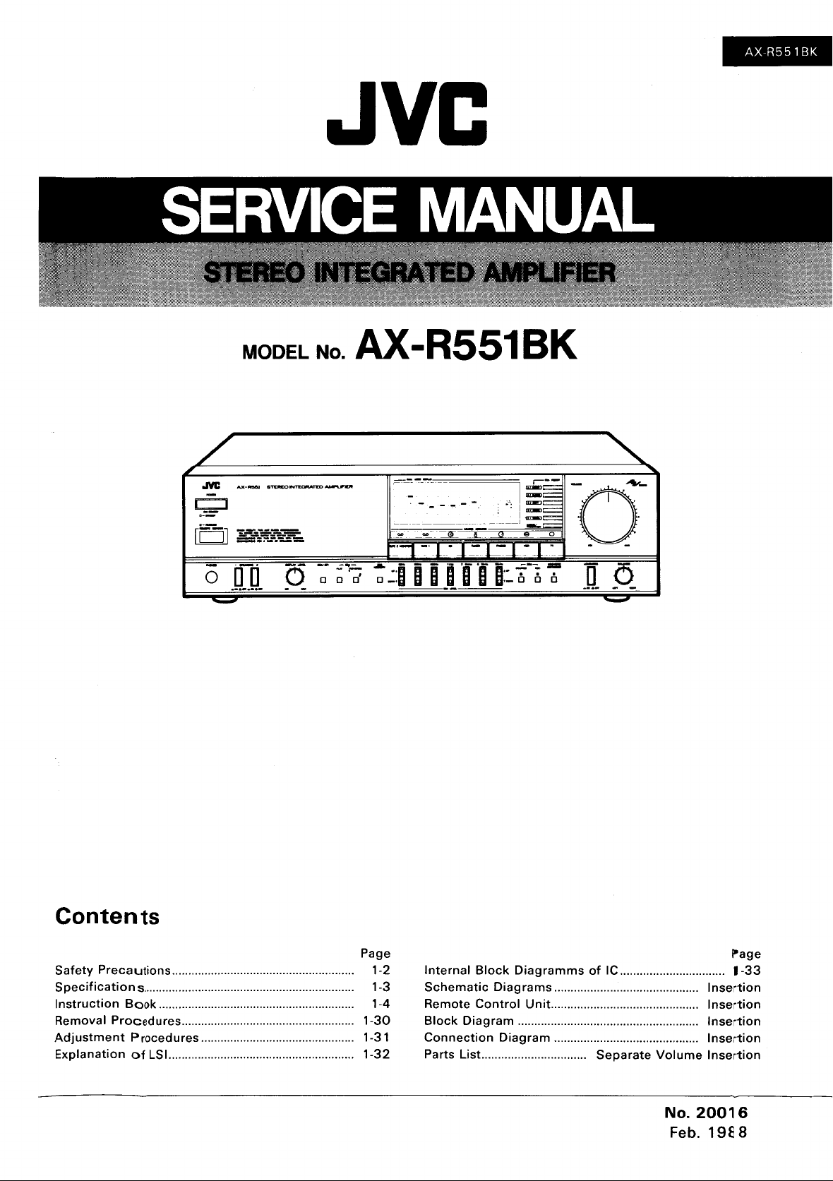
JVC
MODEL No. AX-R551BK
~
- - -- ._.
0'
~
-
-------------
r-~-
"
:-,1
-
~-_
-'1"
0
-- -
=sir
D
-
-
1-1
'0'0
0
-
•
;
_____ I __
0_
D"
8T£MOINTUlRATED
AX·~
-
:=..-=t:C--:.?J:--=-=
0
.D
..
O.
d
"
-
~
_.
-
..
-
-
..-
0
0
-
,~:
l:g~
I=~
-=
0
e
1:'"1"
-
Cl
-
0 0
"
0
_0.
-
C
- -
"
AX
R551
BK
Contents
Safety
Specification
Instruction
Removal Procedures.....................................................
Adjustment
Explanation
Preca
utions
........................................................ 1·2
s,................................................................ 1-3
Book
............................................................ 1-4
Procedures ............................................... 1-31
of
LSI
.........................................................
Page
1·30
1-32
Internal
Schematic
Remote
Block
Connection
Parts List................................
Block
Diagrams
Control
Diagram
Diagram
Diagramms
............................................
Unit.............................................
.......................................................
............................................
of
IC
................................
Separate
Insertion
Insertion
Insertion
Insertion
Volume
No.
Insertion
20016
Feb, 19S 8
i»age
1-33
Page 2
AX-R551BK
'-Safety
1.
The
design
For
continued
manufacturer. Replacement parts must be identical
formed by qualified personnel only.
2. Alterations
should
relieve
the
3. Many electrical and mechanical parts
are often
using replacement
safety
characteristics are identified
are identified by shading
stitute
replacement which does
the
Parts List
in
4.
The
leads
live parts, high
When service
have been returned
5.
Leakage
After
re-assembling
(antenna terminals, knobs, metal cabinet, screw heads,
is
safe
to
Do not use a line isolation transformer during this check.
• Plug
from each exposed metal part
chassis,
• Alternate check
Plug
tivity
tween
Measure
AC voltmeter.
Move
part, particularly
return path
age across
AC
outlet
measured must
corresponds
Precautions----------------,
of
this
product
protection,
of
the
design
not
be made.
manufacturer
not
evident from visual inspection nor can
components
of
Service Manual may create shock, fire, or
in
the
products
temperature
is
required,
to
current
the
the
check (Electrical shock hazard testing)
operate
in
an exposed metal part and a known good
the
without
AC
line cord directly into
to
a known good earth ground. Any leakage
method
AC line cord directly into
the
following manner. Connect a
the
AC voltage across
resistor
to
the
the
resistor. Now, reverse
and
repeat each measurement. Any voltage
not
to
0.5
contains special hardware and may circuits and
no changes should be made
or
circuitry
Any
design alterations
of
responsibility for personal injury
on
the
not
are routed and dressed
parts, moving parts
the
original lead routing
normal, after re-assembling.
the
product,
danger
connection
any
exposed metal part having a
chassis, and measure
exceed
mA
AC
0.75
(r.m.s.).
of
in
the
rated for higher voltage, wattage, etc. Replacement
in
the
schematics and by (Ll",)
have
the
always perform an isolation check
of
electrical shock.
the
of
the
the
the
resistor with
to
each exposed metal
the
VAC
to
the
to
those used
the
product
or
product
Parts List
same safety characteristics
with
and/or
AC
outlet.
cabinet, particularly
AC
outlet.
1,500 n 10
the
AC
plug
(r.m.s.). This
should
additions will void
have special safety-related characteristics. These characteristics
the
of
Service Manual. Electrical
ties, clamps, tubings, barriers and
sharp edges for
and
dress should be observed, and it should be confirmed
headphone
Using a "Leakage Current
current
Use an AC voltmeter having
earth
the
volt-
in
the
not
or
property
protection
on
the
other
any
must
W resistor paralleled by a
ground.
Good
components
original design unless authorized
in
the
original circuits. Service should be per-
be made. Any design alterations
the
manufacturer's warranty and will
damage resulting
afforded by
Parts List
hazards.
the
jack, control shafts, etc.)
exposed metal
not
in
the
as
the
recommended replacement part shown
prevention
on
the
exposed metal parts
Tester",
exceed
0.5
f9
,-----t-o o-r--
0.15,.F
specially for safety purposes.
therefrom.
them
necessarily
parts
which have these special
components
Service Manual. The use
the
of
electric shock and fire hazard.
measure
part
having a return path
mA
AC (r.m.s.) .
1,000
ohms
0.15
ETI
AC
TYPE
having such features
like
to
to
per volt
I1F
AC-type capacitor be-
AC VOLTMETER
(Having
or
more sensitivity. I
1 1
150011
~
earth ground
IOW
in
writing by
of
the
product
further
be
obtained
of
a sub-
be separated from
that
of
the
product
be sure the
the
1000
Place
on each
metal
leakage
or
more sensi-
ohms/volt,
t~is
ptr1:_
product
current
to
probe
exposed
the
by
they
the
\
VVarning----------------------------------~
1.
This
2.
It is the legal responsibility
3.
Repairs
4.
It is essential
5.
If
1-2 (No.
equipment has been designed and manufactured
of
the
must
be made
that
safety critical
mains voltage selector
20016)
repairer
in
accordance with
components
is
provided, check setting for local voltage.
to
ensure
the
are replaced by approved parts.
to
meet international safety standards.
that
these safety standards are maintained.
relevant safety standards.
Page 3
5 pecifications
Output
For
Other areas:
100
watts per channel,
channels
20
harmonic
100
channels
no more
tion.
For
85
(DIN).
75
nels driven,
kHz,
monic
80
nels driven,
more
tion.
(measured
Total
distortion
Power band
Frequency response
driven,
kHz,
with
no more than 0.03%
distortion.
watts per channel, min. RMS,
driven,
than
0.007%
Europe,
watts
watts
watts per channel,
harmonic : 0.03% (20
Australia,
per channel
per channel,
into
with
no
more than 0.007%
distortion.
into
than 0.003%
by
JVC
width
into
into
8 ohms
8 ohms at 1 kHz
min.
8 ohms
8 ohms at 1
total
Germany and
into
min.
min.
total
Audio
20
kHz,
100
watts
area)
0.007% (20
20
kHz,
75
watts
Europe, Australia,
Germany and U. K.)
:
10
Hz - 30
IHF
0.2%, 8 ohms,
both
(For
7 Hz IHF
0.05%, 8 ohms,
both
(For
Germany and
10Hz
+0.5,
(For
Hz
6
+0.5,
(For
Germany and
RMS,
from
harmonic d istor-
8 ohms at 1 kHz
RMS,
both
from
20
total
RMS,
both
harmonic
Analyzer
Hz
-
8 ohms) at
(For
Hz-
8 ohms) at
(For
kHz
channels driven)
other
area)
60
kHz
channels driven)
Europe, Australia,
other
- 70
Europe, Australia,
- 50 k Hz,
-3
dB
(8 ohms)
areas)
kHz,
-3
dB
(8 ohms)
U.K.)
U.
both
20 Hz
total
both
kHz
with
U.K.:
chan-
Hz
to
har-
chan-
with
distor-
System)
other
('66
('66
K.)
to
20
no
Input
terminals
Input
sensit
ivity
impedance
PHONO :
TUNER,
TAPE
TAPE 2 MONITOR
Signal-to-noise ratio
PHONO
TUNER,
TAPE
TV,
TAPE
MONITOR
S.E.A. graphic equalizer
Center frequencies:
Contro
ness
Loud
(Volume
-30
dB
PH
ONO
RIAA
deviation
Record ing
Output
TAPE
VCR
REC
GENERAL
Power source
Dimensions
Weight
and
Design
without
notice.
/
(1 k Hz)
CD,
1,
VCR,
TV,
CD,
1, VCR
2
I range
controls
control
position)
level/impedance
REC-l,
at
output
2 :
specifications subject
2.5
mV/47
mV/35
('66
('78
(DIN)
('66
('78IHF,
Out)
(DIN)
160
2.5
kHz,
16
±1
(at 100 Hz)
(at 10
dB
Hz
- 20 kHz)
mV/l.8
to
the
(W)
x 117 (H) x
(D)
mm
kohms
kohms
IHF)
IHF,
IHF)
Hz,
kHz,
dB,
: 200
: 70
dB
78dB
Out)
67
dB
: 97
dB
74dB
Speaker
68
dB
63
Hz,
1
kHz,
6.3
:
+12dB
-12dB±ldB
:
+4dB
+4dB
: ±0.5
(20
200
Refer
back page.
:
435
345
17
-3/16" x 4-5/8"
13-5/8")
: 9 kg (19.8 Ibs)
Rec
400
kHz
kHz)
kohms
table on
to
change
AX-R551 BK
Hz,
x
POWER
SPECIFICATIONS
Continental Europe
U.K.
Austral
ia
U.S.
Military
Other
areas
Areas
Market
AC 220 V
AC
240
AC
110/
Line
Av,
50
Hz
V Av, 50
Hz
120/220/240
Voltage
V
& Frequency
Av
seiectable,
50/60
Hz
Power
Consumption
205
watts
475
watts
220
watts
(No.
2,)~
16)
1-3
Page 4
AX-R551
BK
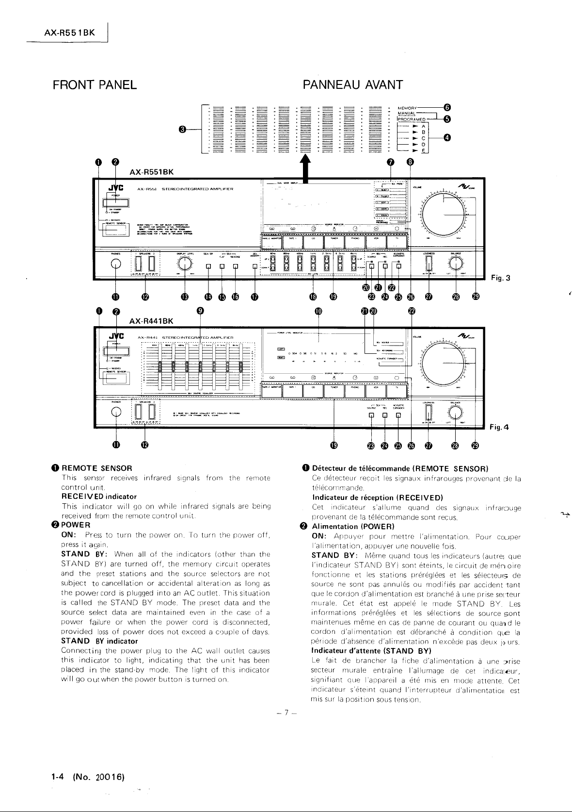
FRONT
PANEL
AX-R551BK
.-~,....,-""""'~
,..---.,""~-~
~"",,"""-'''''''O£T'BO~
__
....
,_c.--....~
-~"",,,,,,,,,,,,,,,,,,
8 :
{
.....
.....
-
=
-=
:
==
:
.=
.=
.=
.=
.=
PANNEAU AVANT
IPROGf.'lA~~
~
MEM
ORV---0
MANUAL
---,
~A
~
B
~C
~
D
~
"
__
e
Fig.3
o
REMOTE
Th
is
control
RECEIVED
This
received from
f)
POWER
ON:
press
STAND
STAND
and
the
subject
the
power
is
called
source
power
provided
STAND
Connecting
this
indicator
placed
will
go
SENSOR
sensor receives
unit.
indicator
indicator
Press
it
out
will
the
remote
to
turn
again.
BY:
When all
BY)
are
turned
preset
stations
to
cancellation
cord
is
the
STAND
select data are
failure
or
loss
of
power
BY
indicator
the
power
to
the
when
light,
stand·by
the
in
infrared
(10 on
the
or
plugged
BY
maintained
when
plu~l
power
•
-'''-'''''''''''':'''"''-'ll''''''''~'''''-'-'''-'
.".
'->.<' ~ ..
"'-
"""
while
control
power
on
of
the
off.
the
and
the
accidental
into
an
mode.
the
power
does
not
to
indicating
mode.
The
button
signals
Indicators
the
from
infrared
unit
To
turn
memory
source selectors are
alteration
AC
outlet.
The
preset data and
even in
cord
exceed a
AC
wall
that
the
light
is
turned
..
,,"'..,
the
remote
signals are being
the
power
(other
than
circuit
operates
as
long
This
situation
the
case
is
disconnected.
u)uple
outlet
unit
of
this
on
of
of
days
causes
has
been
indicator
off.
the
not
the
as
Fig.4
o Detecteur
Ce
telecornmande.
Indicateur
Cet IrlClicateur
provenant
f}
Alimentation (POWER)
ON:
I'alimentation,
STAND
I'indicateur
fonctionne
source ne
que
a
murale. Cet
informations
maintenues
cordon
perlode
Indicateur d'attente
Le
secteur
signifiant
Inclicateur
rnis sllr
de
cJetecteur
cle
Appuyc3[
BY:
le
cordon
d'al
d'ahsence
fait
de
mllrale
que
la
position
telecommande
recoit
les
signaux infrarouges
de
reception
la
appuyer
Meme
STAND
et
sont
(j'alimentation
etat
prereglees et
meme
imentation
(RECEIVED)
s'allume
telecommande
pour
mettre
line
quand
BY)
les
stations
pas
annules ou
est appele
en
cas
est
d'alimentation
(STAND
brancher
s'etelnt
la
entralne
I'apparell a ete rnis
quand
sous tension.
(REMOTE
quand
cles
sont
recus.
I'alimentation.
nouvelle
sont
prereglees et
cle
debranche a
fois.
tous
les
indicateurs
eteints,
modifies
est
branche
le
mode
les
selections de source
panne de
n'excede
BY)
fiche
d'alimentation
I'allurnage
I'intorrupteur
en
SENSOR)
provenant
signallx infrarDuge
Pour
couper
circuit
les
par
(autres
de
men
selecteur5 de
acciclent1ant
le
a une prise sec1eur
ST
AN
D
BY
courant
ou
condition
pas
deux
qua~
qce
10
a une
cle
cet
indlcat€ur,
mode
attente. Cet
(j'alirnentation
de
que
oire
Les
sont
d le
urs.
?rise
est
la
la
-7-
1-4 (No. 20016)
Page 5
AX-R551
BK
Note:
Even
•
when the POWER button
receiver
watts), To
the power cord.
consumes a small
shut
the power
o SPECTRO PEAK indicator/SEA
indicator
This display doubles
and
ed
SPECTRO PEAK
divided
quencies are identical
SPECTRO
level
cator
rising and slower when decaying.
SEA
falls in response
SEA
quency band.
Notes:
• The SEA
•
o
SEA
Pressing
indicator
set
particular mode
pattern
light. These indicators also light when
button
store a newly-created pattern in
o
MANUAL!PROGRAMED
Pressing
"MANUAL"
indicating
o MEMORY indicator
This
MEMORY
to accept the pattern you have created
memory.
(AX·R551
an
SEA
between display
into
in
each
is
designed
GRAPHIC
LEVE L buttons
shown
for about five
is
applied.
When a signal
DICATOR,
for 5
seconds
FLAT,
SEA
or SEA
MEMORY
PRESET indicator (AX-R551 BK only)
the
A,
pattern
was
was
has
the
which
indicator
button
BK
only)
GRAPHIC
seven
PEAK
frequency band. For
GRAPHIC
SEA
SEA REVERSE,
MANUAL/PROGRAMED
B,
C,
being used, no preset
been pressed,
MANUAL/PROGRAMED
or
lights
as
EQUALIZER
by
pressing
INDICATOR:
frequency bands, whose center fre-
to
those
INDICATOR
so
that
EQUALIZER:
to
the pressi
to
show
seconds
level
is
displayed by SPECTRO PEAK IN-
GRAPHIC
by
pressing
button.
D,
or E to
being
used
(MANUAL
indicator
"PROGRAMED"
mode
has
(AX·R551BK
for
is
pressed,
is
amount of electricity (5
off
GRAPHIC
a SPECTRO
the
SPI/SEA
The
of
the
shows the
its response
The
ng
the
EQUALIZER
immediately after power
EQUALIZER
SEA
MANUAL!PROGRAMED
light,
the
last
time
or
PROGRAMED)
to
select a preset pattern
memory.
to
been selected.
only)
about
indicating
set
to
STAND
completely, disconnect
PEAK
indicator.
output
seven
SEA
easy
viewing, the indi-
time
dot
of
the
SEA
level in each fre-
level
LEVE
L,
button
according
the
pattern
an
(AX·R551BK
light on the display,
five seconds when the
the
BY~
EQUALIZER
indicator
It
is
switch-
button.
signal
bands. This
output
signal
is
faster when
point
rises
correspondi
indicator
is
displayed
SEA PRESET,
will
cause
to
which
pre-
unit
was
in
that
If
no preset
indicator
SEA
button
unit
for
will
PR
ESET
or
only)
causes
is
ready
storage in
this
and
ng
to
Remarque:
la
• Meme quand
BY, cet ampli·syntoniseur consomme un
cite (5 watts). Pour couper comphHement I'alimentation,
debrancher
8 Indicateur
phique SEA (SPECTRO PEAK
PHIC
Cet affichage
spectre et
la
is
is
commutation
touche SPI/SEA.
SPECTRO PEAK
de
dont
des
INDICATOR
chaque gamme de frequences. Pour une
I'indicateur
reponse
de
la
SEA
cend
correspondantes
gamme
Remarques:
• L'indicateur
indique pendant environ cinq
apres
• Lorsqu'un
PEAK
PRESET, SEA
PROGRAMED
chage
cinq
(»
Indicateur
(AX·R551BK
Une pression sur
fera s'allumer
prereglee utilisee
mode
forme
lumera.
SEA
prereglee ou
creee.
o Indicateur
(MANUAL!PROGRAMED)
Une pression sur
fait
chage
o Indicateur
ment)
Une pression sur
MORY"
I'appareil
de
EQUALIZER)
indicateur
sortie
sont
les
frequences centrales sont identiques
sept touches SEA. Cet indicateur SPECTRO
soit
descente.
GRAPHIC
en
reponse a
de
frequences.
que I'alimentation
INDICATOR,
montre
secondes.
de
particulier
n'etait
Ces
PR
ESET a ete
de
s'allumer
indiquant
de
pendant environ cinq secondes, indiquant
est
touche POWER
le
cordon d'alimentation.
cretes
de
spectre/de
(AX·R551BK
est a double
entre
INDICATOR:
analyses
indique
est
con(:u
plus rapide lors
EQUALIZER:
la
pour
de
niveau
niveau
FLAT,
ou
le
SEA
formes SEA
seulement}
I'indicateur
la
derniere fois que I'appareil
(MANUAL
utilisee, aucun indicateur de
indicateurs s'allument
pour
mode manu el/programme
"MANUAL"
le mode selectionne.
memoire
la
pret
a memoriser
usage:
de niveau d'egaliseur graphique SEA et
les
affichages
pour
le
niveau
de
maniere
pression sur
indiquer
SEA
est
de
signal
si
la
SEA REVERSE,
SEA
MEMORY
GRAPHIC
prereglees
la
touche
A,
ou
pressee
memoriser une
(AX·R551BK
la
touche
ou "PORGRArv'E
(MEMORY)
touche SEA
est
placee
sur
STAND
peu
d'electri·
niveau
se
fait
niveaux
d'egaliseur gra·
en pressant la
des
signaux
INDICATOR/SEA
seulement)
indicateur de cretes de
Les
sept gammes de frequences
cl
PEAK
de
signal
de
sortie dans
verification
cl
ce
que
sa
duree de
de
la
montee et
Le
les
le
niveau SEA dans chaque
GRAPHIC
secondes
fournie.
est
affiche
touche SEA
EQUALIZER
(SEA PRESET)
MANUA
B,
C,
D ou
PROGRAMED).
aussi
pour
selectionner une
MANUAL/PR
MEMORYa
la
forme que vcus
plus
lente lors
point
monte
touches
EQUALIZER
immediatement
par
est
L/FR OG RAME D
E,
quand une
forme n ouvellement
seulement)
(AX·R551BK
et
SEA
LEVEL
le
SPECTRO
LEVEL,
MANUAL!
~ressee,
selon
'orme
I'affi·
pendant
la
forme
etait
dans
Si
aucune
ne
touche
forme
OGRAMED
D"
cl
I'affi-
seule·
Ilume
"ME-
avez
creee.
GRA·
celles
aisee,
des-
est
SEA
ce
s'al-
que
-8-
(No.
21)()
1 6) 1- 5
Page 6
AX-R5518K
o SEA PRESET (AX-R551
Press
to
store
recall
the
pressed. While in
MEMORY
the
patterns
mode,
priate
be
stored
A
different
PROGRAMED
SOFT,
stored
not
be
more
o
details, refer
MANUAL/PROGRAMED
Press
to
S.
E.A. pattern modes.
the
preset S.E.A.
button
you
that
pattern
SEA PRESET
for
recall in this way.
set
of
mode. These 5 patterns
MOVIE
in
memory
replaced. So,
switch between the
BK
displayed S.E.A. pattern in
the
and then one
have created. Later,
can
S.E.A. patterns
and
before the
up
to
page
only)
pattern
MANUAL
be
recalled
button.
Up
VOCAL)
to
10 patterns may
33.
corresponding
mode, pressing
of
these 5
while
by
pressing
to
5 original patterns
is
available when in
(HEAVY,
have been permanently
unit
was
shipped, and may
(AX-R551BK only)
MANUAL
and
memory
to
the
the
button
will
MANUAL
the
CLEAR,
be
recalled. For
PROGRAMED
o SEA controls (AX-R441BK only)
The
built-in
into
63 Hz
When
quency
±1O
dB
63 Hz:
organs, drums, etc.
emphasis and eliminates the unclear sound response
low
frequencies
160 Hz: Emphasize
sound. Oe-emphasize
large
400
Hz: This frequency range
is
constructed. Emphasize
1 kHz: Most effective in emphasizing
the human voice. Emphasize
brought
it
to
recede
2.5
kHz:
music sounds hard
6.3
kHz:
frequency
the subtleties
16
kHz:
the delicacy
in a
extension.
pensate for cartridge response since most moving-magnet
cartridges
from
4D
POWE R
This
indicator
graphic equalizer divides the audio spectrum
seven
frequency
to
16
kHz at intervals
the
S.E.A. level
response
by raising
Raise
or
nearly
to
the foreground,
into
This frequency stimulates the human ear.
Boost
band varies the
of
Boosting this frequency range
of
more
ear-pleasing manner, and provides a feeling
This frequency band
have
10
kHz
to
lEVEL
lights according
bands
with
center frequencies
of
4/3
is
set
is
flat. The response
or
lowering the knob.
to
emphasize the
It
produces stable and solid sound
with
de-emphasis.
to
obtain
to
empty
the
the music.
highs,
their
eliminate
listening rooms.
background.
or
metallic, de-emphasize.
to
add
clarity
with
cymbals and triangles resounding
resonance peaks in the frequency range
octave.
to
"0"
(center
can
low
bass
a more expanded
unclear sound caused by
is
the
base
to
put
a punch
to
or
to
tonal
or
cause the vocalist
de-emphasize
winds and strings. This
expression, influencing
can
also
20 kHz.
INDICATOR
(AX-R441
to
the
output.
position),
be
varied by
response
on
which
to
your
de-emphasizing
to
properly
be
BK
used
only)
adds
to
or
to
button
SEA
store
appro-
can
the
from
fre-
of
with
of
low
music
music.
to
be
cause
If
the
to
of
com-
o
Touches
de
preniglage
SEA (SEA PRESET) (AX-R551
seulement)
Presser
pour
rappeler
touche
touche
morisera
MANUAL,
touche
originales peuvent etre memorisees
Un ensemble
mode
SOFT,
risees
placees. Ainsi, jusqu'a
Pour plus de details,
memor;ser
la
forme
pressee.
SEA
MEMORY
la
forme
cette
SEA
PRESET appropriee. Jusqu'a
different
PROGRAMED.
MOVIE
avant
et
la
sortie d'usine et
la
forme
S.
E.A. prereglee correspondant a
En
mode
MANUAL,
et sur une de
que vous
forme
VOCAL)
avez
peut etre rappelee
de
formes S.E.A. est
Ces
cinq formes
10 formes peuvent etre rappelees.
voir
page
o Touche manu el/programme
(MANUAL/PROGRAMED)
La
presser
pour
S.E.A.
MANUAL
o Commande
L'egaliseur graphique incorpore divise
sept gammes
vont
de
Quand
la
La
abaissant cette commande.
63
des
stable et solide
peu claire
160
La
salles d'ecoute
vides.
400
la
votre
1 kHz:
la
au
soliste
63
le
n iveau
reponse
reponse peut
Hz: L'elever
graves d'orgues, tambours, etc. Elle
des
Hz: L'elever
baisser
Hz: Cette gamme
musique
musique.
La
voix
humaine. L'elever
premier plan ou
a I'arriere-plan.
commuter
et
de
SEA (AX-R441BK seulement)
de
frequences
Hz
a 16 kHz a
S.
E.A.
en
frequence est
!ltre
pour
avec
basses
pour
pour
eliminer
de
est
construite. L'elever
plus efficace
2,5 kHz: Cette frequence
musique semble dure ou metallique
6,3 kHz: L'augmenter
instruments
diversifie I'expression tonale,
musique
a vent et a cordes. Cette gamme
16 kHz: Une augmentation
ajoute a la
resonnant
un
effet
etre utilisee
que
de
resonance
del icatesse
d'une
maniere plus laissante a
d'extension. Cette gamme de frequences peut
pour
la
majorite
des
dans
compenser
la
a 20 kHz.
4D
Indicateur
(POWER
Cet
de
LEVEL
indicateur
niveau
INDICATOR
s'allume suivant
(AX-R551BK seulement)
PROGRAMED.
est
regie sur
uniforme.
variee de ±10 dB, en elevant ou
mettre
emphase et
frequences par une
obtenir
le
son peu clair provoque par
grandes dimensions ou
de
frequences
pour
pour
la
diminuer
stimule
pour
de
des
hautes,
cellules a aimant
gamme
de
d'alimentation
S.E.A.
affichee
une pression sur
ces
cinq
creee. Plus
ont
ete
ne
pour
definitivement
peuvent
touches metard,
en
cinq
le
rappel.
disponible
(HEAVY,
pas
pressant
etre rem-
33.
entre
les
modes de formes
le
dont
des
intervalles
en
valeur
elimine
un son grave plus etendu.
mettre
amener
ajouter
influencant
cette
la
reponse
frequences allant
(AX-R441BK
le
debit.
spectre audio
les
frequences centrales
de
"0"
est
pour
en
pour
I'oreille
diminuer.
gar1)me
les
cymbales et triangle
mobile
4/3
(position
la
tres
basse
produit
la
reponse sonore
diminution.
pratiquement
celle sur laquelle
donner
du punch a
valeur ou
la
voix
d'un
reculer
la
humaine.
de
la
clarte aux
de
frequences
les
subtilites
de
frequences
I'oreille
et
de
cellule du
ont
leur cr§te
de
seulemenc:))
centrale),
diminuer
BK
ou
pour
en
mode
formes
CLEAR,
memo-
octave.
reponse
un son
eJes
soliste
voix du
Si
d~
proauit
a~
fait
10 kHz
la
la
la
en
en
la
la
ssi
1-6 (No. 2001
-9-
6)
Page 7
Q)
PHONES (Headphone Jack)
Plug
stereo headphones
and
record
from
to
OFF.
~
SPEAKERS
SPEAKERS 1:
the
SPEAKERS 1 terminals
SPEAKERS 2:
the
SPEAKERS 2 terminals
Note:
• When speakers
SPEAKERS
button
pressed, sound will not
system. When
either or both
will
4i)
DISPLAY
Adjusts
PEAK
be
displayed in an easy-to-see
effect on
~
SPI/SEA
Press
PEAK
level
4P
SEA
Press
~
SEA
Press
fj
SEA
Press
for
about
SEA PRESET
currently
~
SEA
The
intu
63
HL
When
quency response
varied
LEVE L
Buttons
the
same
continue rising
63
Hz:
organs, drums,
With
of
low
160
Hz:
De-emphasize
or
nearly
400
Hz:
IS
constructed.
monitoring
the
headphones
Press
Press
terminals,
of
the system connected;
two
SPEAKERS
be
heard from either or both speaker system(s).
LEVE L (AX-R551
the
relative
INDICATOR
the
output
(AX-R551
to
SWitch
INDICATOR
indicator.
FLAT
this
button
REVERSE
this
MEMORY
this
being
LEVEL
built-in
seven
to
16 kHz at intervals
the S.E.A. level
up
buttons.
for
time,
Raise to emphasiLe the very
emphasis and
frequencies
Emphasile
empty
This
the
(AX-R551BK
for a flat
(AX-R551BK
button
to
(AX-R551BK
button
and
five seconds. While It
buttons
displayed,
(AX-R551BK
graphic
frequency
is
to
flat.
±12
dB
different
and
or
falling.
etc
el
with
to
eliminate
listening rooms.
frequency
EmphasiLe
into
this
Jack
for
private
If
you
want
only,
press
to
switch
on
or
to
switch
on
or
are
connected
press
be
pairs
of
speakers
buttons
BK only)
display
so
sound level
BK only)
equali7er divides the
holding
It
iminates the unclear sound response
to
position
that
weak
position.
indication
and
SEA
only)
response
reverse
to
bands With center frequencies
by
frequency
only)
the
only)
the
MEMORY
store in
refer
to
only)
of
4/3
is
set
to
The response in each band can
pressing the
them
produces stable and solid sound
de-emphasis.
obtain a more
unclear sound caused by large
range
is
to
put
to
the
SPEAKERS
the speakers
off
the speakers
off
to
only one of the
only the
if
heard from either speaker
"0"
a punch
both buttons
are connected and
are
on
or
strong level signals can
This
between
GRAPHIC
pattern's
indicator
is
lit,
press one
memory
page 34.
bands can
down
the basis on
the
octave.
(center
UP
causes the level
low
bass
expanded
to
listening
listen
to
sound
buttons
connected
connected
SPEAKERS
pressed, sound
the
SPECTRO
control
has
the
SPECTRO
EQUALIZER
characteristiCS.
will
of
SEA
pattern
audio
spectrum
position),
or
DOWN
be
pressed at
response
low
sound.
which
your
music
music.
are
light
the
from
fre-
SEA
to
to
no
be
to
of
Q)
Prise
de
casque
Y brancher un casque
prive et
ecouter
les
touches
~
Haut-parleurs
SPEAKERS
raccordes aux bornes
SPEAKERS
raccordes aux bornes
Remarque:
• Ouand
de
bornes
systeme raccorde,
fonces,
les
deux paires sont raccordees et que I'une
SPEAKE
audible soit d'un systeme de haut-parleurs, soit
4i)
Niveau d'affichage
(AX-R551BK
la
Regie
PEAK
particulierement
position
une
le
niveau
~
SPI/SEA
Presser
INDICATOR
EQUALIZER.
G)
SEA
FLAT
Presser
~SEA
tfI
~
REVERSE
Presser cette
la
forrne.
Memoire SEA
Presser
pendant
presser uno
forme
SEA
page 34.
Niveau
SEA
L'egaliseur
en
sept gammes de frequences
vont
de 63
Quand
la
reponse
La
reponse dans chaque gamme
±12
dB
Les
touches
peuvent etre pressees
pressees
tinue
du niveau
63
Hz:
des
graves d'orgues, tarnbours, contrebasses.
son stable et solide avec ernphase et
sonore peu claire
160
Hz:
La
baisser
salles
d'ecoute
vides.
400
Hz:
la
rnusique est
a
votre
musique.
d'ecoute (PHONES)
le
contr61e
le
son
provenant
SPEAKERS
(SPEAKERS)
1: Presser
2: Presser
les
haut-parleurs
SPEAKERS,
le
son
RS
ou
seulement)
position
INDICATOR
facile a lire. Cette
dll
son de sortie.
(AX-R551
pour
commuter
et
(AX-R551BK
cette
touche
touche
(SEA
cette
touche
environ
des
touches
actuellernent
(SEA
graphique
H7
a 16 k Hz a
le
niveau S
en
frequence est
en
pressant
pour
provoque
L'elever
L'elever
pour
eliminer
de grandes dimensions
Cette gamme de frequences est cele sur laquelle
constrllite
d'ecoute
de
I'enregistrement.
sur
pour
SPEAKERS 1 en
pour
SPEAKE
si
les
ne
sera
les
deux sont enfoncees,
(DISPLAY
relative de I'affichage sur le
pour
fort
ou faible puissent etre
BK seulement)
I'indication
I'indicateur
pour
une reponse un
(AX-R551BK
pour
MEMORY)
et
I'indicateur
cinq
secondes. Pendant
SEA
affichee. Pour plus de details,
LEVE
L)
incorpore
des
E.A
est regie sur
les
touches UP ou
des
gammes de
en
une
augmentation
pour
rnettre en valeur
des
basses
pour
obtenir
le
stereo
du casque
OFF.
commuter
commuter
RS 2 en
ne
sont raccordes qu'a paire
n'enfoncer que la touche du
deux commutateurs sont en-
audible d'aucun systeme. Ouand
LEVEL)
que
les
touche
de niveau
seulement)
seulementl
inverser
(AX-R551
PRESET
(AX-R551
divise
dont
les
intervalles de
"0"
uniforme.
peut
meme ternps
frequences par
un son graVl
son peu clair
L'elever
AX-R551
pour
I'ecoute
Si
uniquement,
et hors
et hors
entre
les
MEMOR(
DOWNSEA
frequenc"s
pour
vous voulez
les
haut-parleurs
circuit.
les
haut-parleurs
circuit.
des
le
son
des
signaux de niveau
iforne.
cararteristiques
pour
BK
frequences centrales
(posi:i
ou
la
elimil8
SPECTRO
affiches
n'a pas
d'effet
SP~CTRO
SEA
GRAPHIC
~K
seulement)
va
s'allurner
q!'
il
est
mernoriser
SELJ
lement)
le
spectre
4/3
octave.
on
centrale),
etre
modifiee
LEVE
differentes
et
les
maintenir
din
inution
tresbasse reponse
Ell e produit
la
ure
diminution.
plus
pro:oque
ou p ratiquement
dorn
er
du punch
BK
en
presser
touches
sera
deux_
dans
sur
PEAK
de
allume
la
voir
audio
de
L.
con-
un
reponse
etendu.
par des
-10
-
Page 8
AX-R551
BK
1 kHz: Most
the
human
brought
it
to
recede
2.5 kHz: This
music sounds hard
6.3 kHz: Boost
frequency
the
subtleties
16 kHz: Boosting this
the
delicacy
more
in a
extension.
pensate
cartridges
from
Cl)
10kHz
SOURCE
TAPE 2 MONITOR:
connected
this
button
selected
effective
voice. Emphasize
to
the
into
frequency
band varies
of
of
highs,
ear-pleasing manner, and provides a feeling
This
for
cartridge response since most moving-magnet
have
their
to
20
in emphasizing
foreground,
the background.
to
the
frequency
stimulates the human ear.
or
metallic,
add
clarity
the
music.
frequency
with
cymbals and triangles resounding
resonance peaks in the
kHz.
SELECTOR
Press
to
the
TAPE
will
release
this
by
another source select
Note:
• Press this button
ing
to
the sound just recorded)
tape
deck.
TAPE
1:
Press
TAPE
1 terminals.
CD:
Press
connected
TUNER:
PHONO:
PHONO
VCR:
connected
TV:
connected
W
SEA
This
been pressed
fj
SEA
This
pressed
~
ACOUSTIC EXPANDER indicator
This
button
@)
SEA
Press
sound.
~
SEA
Press
this
to
Press
Press
terminals.
Press
to
Press
this
to
SOURCE indicator
indicator
REC
indicator
indicator
to
ON.
indicator
has been pressed
SOURCE
th
is
button
REC
this
button
to
monitor
to
listen
to
button
the CD terminals.
this
the VCR terminals.
the
lights when
to
ON.
lights when the
to
this
button
to
listen
to a turntable
button
to
button
to
listen
TV
terminals.
lights when the
to
ON.
to
I isten
to
record
SE.A-compensated
Note:
•
S.E.A.
recording
terminals are used but
is
possible when the TAPE 1 or VCR
is
terminals are used.
or
to
cause
or
de-emphasize
de-emphasize.
to
winds
tonal
expression,
range
band can also
to
listen
2 terminals.
function
button
de-emphasizing
the
vocalist
to
and strings This
influencing
properly
be
used
frequency
to
a cassette deck
Press
again, and
so
that
the
may
be heard.
the recorded sou nd
when
using a three·head
a cassette deck connected
listen
to a compact
to
listen
to
listen
to
the sound
to
the sound
the
SEA
SOURCE
SEA
REC
ACOUSTIC
to
the S E.A. -compensated
not
possible when the TAPE 2
disc
a radio broadcast.
connected
of
the
from
button
button
has
EXPANDER
signals.
to
cause
If
adds
to
com-
range
source
(I
isten·
player
to
VCR
the
been
be
the
to
of
to
the
TV
has
1 kHz:
la
au
soliste
2,5 kHz: Cette frequence
musique semble dure
6,3 kHz: L'augmenter
ments
diversifie I'expression tonale,
la
16 kHz: Une
aJoute
resonnant
un
etre utilisee
que
de resonance dans
10
~
Selecteur
TAPE
cassette raccordee aux bornes
sur cette
selectionnee par une autre
puisse etre entendue.
La
voix humaine. L'elever
premier
plus efficace
plan ou
pour
la
diminuer
pour
mettre
amener
pour
a I'arriere-plan.
stimule
ou
metallique,
pour
aJouter de
a vent et a cordes. Cette gamme
influencant
musique.
augmentation
a
la
delicatesse
d'une
maniere plus plaisante a
effet
d'extension. Cette gamme de frequences peut aussi
pour
la
kHz
majorite
a 20 kHz.
de
compenser
des
cellules a
source (SOURCE SELECTOR)
2 MONITOR:
touche
liberera cette
de cette gamme
des
hautes,
les
la
reponse de cellules du
aimant
la
gamme de frequences allant de
Appuyer
pour
TAPE
fonction
touche
Remarque:
• Presser
(ecoute
sation d'une platine
TAPE
raccordee aux bornes
CD:
disque
TUNER:
emission.
PHONO:
aux bornes PHONO.
VCR:
du magnetoscope raccorde aux bornes VCR.
TV:
du televiseur raccorde aux bornes
W Indicateur
Cet
ete pressee sur ON.
~
Indicateur
Cet
pressee sur ON.
~
Indicateur d'expanseur
cette
touche
pour
controler
du son qui vient d'etre enregistre) lors de I'utili·
a cassette a trois tetes.
1:
Appuyer
Appuyer
compact
Appuyer
Appuyer
Presser
Presser
SEA
indicateur
SEA
indicateur
pour
ecouter
TAPE
sur cette
raccorde aux bornes CD.
cette
cette
touche
sur cette
pour
ecouter
touche
touche
1.
pour
touche
un tourne-disque raccorde
pour
ecouter
pour
ecouter
TV.
SOURCE
s'allume quand
la
REC
s'allume quand
la
acoustique
touche
touche
DER)
Cet
indicateur
PANDER
@}
SEA
Presser cette
~
SEA
Presser
SOURCE
REC
s'allume quand
a ete pressee sur ON.
touche
pour
cette
touche
pour
la
touche ACOUSTIC
ecouter un son compense
enregistrer
SEA
Remarque:
• L'enregistrement S. E,A.
TAPE 1 ou VCR
lorsque les bornes TAPE 2
sont
est
possible lorsque les
utilisees
sont
utilisees.
en
valeur ou
la
reculer
I'oreille
diminuer.
la
cymbales et triangles
I'oreille
mobile
ecouter une
2.
Une autre pression
pour
de selection de source
une
platine
ecouter
pour
diminuer
voix
d'un
soliste
la
voix
humaine.
clarte aux instru-
de
les
de
ont
que
le
son enregistre
frequences
subtilites
frequences
et
produit
leur
platine
la
source
Si
fait
crete
a cassette
le
lecteur de
le
le
SEA
SEA
ecouter
son
son
une
provenant
provenant
SOURCE
REC a ete
du
(ACOUSTIC EXRAN·
EX-
S.E.A.
des
signaux compenses
bor
nes
et
n'est pas
p~ssible
la
de
a
a
1-8 (No. 2001
6)
-11
-
Page 9
f1;
ACOUSTIC
When
this
indicator
aural Signal
sounds better.
Notes:
•
•
~
SOURCE indicator
The i
button
lights and the sound image
When a TV
tributor (mono right termi
ACOUSTIC
corded.
nd
icator
pressed
o LOUDNESS
Press
this
button
low
ty at
W BALANCE
Use
speakers.
position.
fj)
VOLUME
Controls the
and
pressed
listening levels.
to
adjust the balance between the
Normally
and
th
is
i nd
to
on.
EXPANDER
button
is
pressed, the
will
be
given a stereo
or VCR
Land
nals
.
EXPANDER
I ight correspond i
to
compensate
set
INDICATOR
volume
icator
I ights when the POWE R
ACOUSTIC
effect
is
monaural,
R) for connecting the left
sound effect cannot
ng
to the
for
the ear's lower sensitivi-
this
control
of
the speakers and headphones,
EXPANDER
is
expanded, a
and a stereo signal
use
the
Land R dis-
SOLI
rce
left
and
to
the center
button
mon-
and
be
re·
selector
right
click
has
f})
Expanseur acoustique
Quand cette
EXPANDER
signal monaural beneficiera
stereo sonnera
Remarques:
• Quand
utiliser un distributeur
et droit) pour
de
droite.
• L'effet sonore
enregistre.
fIillndicateurs
L'indicateur
s'allume.
fj
Contour
Presser
de
I'oreille
@)
Commande
L'utiliser
droite.
declic.
@)
Commande
(VOLUME
Pour
cJ'ecollte. Cet
d'allmentatlon
touche
s'allume et I'image sonore est etendue; un
miellx
le
televiseur
le
ACOUSTIC
de
SOURCE
correspondant
(LOUDNESS)
cette
touche
a de
bas
niveallx d'ecoute.
de
balance
pour
equilibrer
La
placer
normalement
de
volume et indicateur
et
INDICATOR)
controler
le
volume
indicateur
est mis sur
(ACOUSTIC
est pressee,
d'un
ou
magnetoscope
gauche
raccordement
EXPANDER
au
selecteur de source enfonce
pour
compenser
(BALANCE)
les
haut-parleurs de gauche et de
des
s'allume quand
la
position
EXPANDER)
I'indicateur
effet
stereo et un
et droit (mono -
des
sur
haut-parleurs
est
bornes
ne
la
plus
basse
la
position
sous tens;on.
AX-R551BK
ACOUSTIC
s'lgnal
monaural,
gauche
de
gauche
peut
pas
etre
sensibilite
centra
le
et
du
casque
i'interrupteur
et
a
-12
-
(No.
20016)
1-9
Page 10
AX-R551
BK
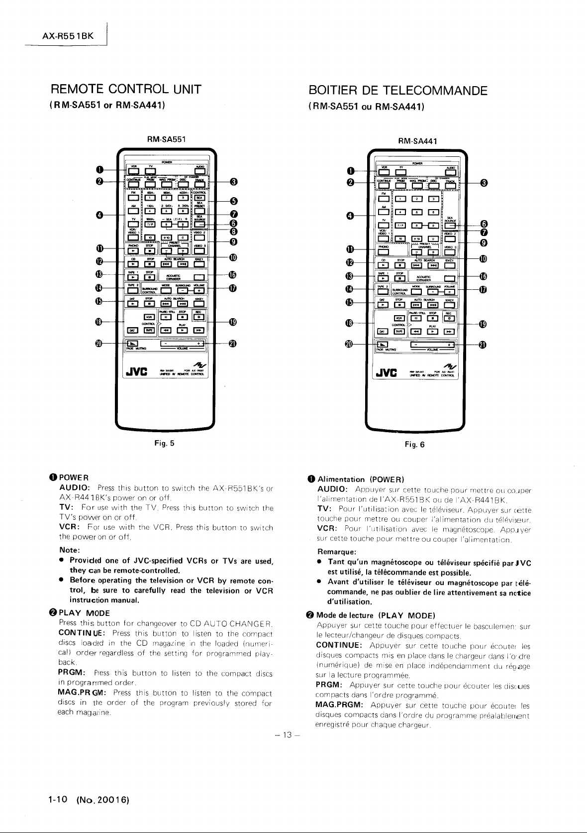
REMOTE CONTROL UNIT
(RM-SA551
or RM-SA441)
RM-SA551
SOITIER
(RM-SA551
DE
TELECOMMANDE
ou
RM-SA441)
RM-SA441
DD
Cl
O:i5p!!~t~[5
o!c:::J
o :
c:::J
m m
CD
m
o
I~~~~~~~~-~
.IVC
Fig_
5
OPOWER
AUDIO:
AX-R441
TV:
TV's
VCR:
the
Note:
• Provided one
• Before operating the television or VCR by remote con-
f)PLAY
Press
CONTIN
discs loaded in
cal)
back.
PRGM:
in
MAG.PRGM:
discs in
each magazine.
Press
this
BK's
power
For
use
power
power
they
trol,
instruction manual,
this
order
progra
with
on
or
For
use
with
on
or
off
can
be
remote-controlled_
be
sure
MODE
button
UE:
Press
regardless
Press
this
mmed
order.
Press
the
order
off
of
to
for
the
button
to
switch
the
on
or
off
the
TV.
Press
this
the
VCR.
Press
JVC-specified VCRs
carefully
changeover
this
CD magaLine in the loaded
of
button
this
of
read
button
the setting
to listen
button
the
program
to
to
to
AXR551
button
this
button
or
the television
CD
AUTO
listen
to
for
programmed
to
the
listen
to
previously
to
switch the
to
TVs
are
or
CHANGER.
the
compact
(numeri-
compact
the
compact
stored
BK's or
switch
used,
VCR
play-
discs
for
-13
o Alimentation (POWER)
AUDIO:
I'alimentatlon
TV:
touche
VCR:
sur cette
Remarque:
• Tant qu'un magmhoscope
• Avant d'utiliser
8 Mode
Apruyer
le
CONTINUE:
disques compacts mis
(numerique)
sur
PRGM:
compacts dans
MAG.PRGM:
disques compacts
enregistre
-
Appuyer
de
Pour
I'utilisa:ion
pour
mettre
Pour l'rJtilisation avec
touche
est
utilise,
la
commande,
d'utilisation.
de
lecteur!changeur de disques compacts
la
lecture programmee.
ne
lecture
sur cette
Appuyer
de mise en
Appuyer
I'ordre
Appuyer
pour
chaque chargeur
Fig. 6
sur cette
l'AXR551
pour
telecommande
le
pas
(PLAY
touche
sur
clans
BK
avec
ou
couper
mettre
televiseur
oublier
MODE)
pour
sur
en
place
rlace
cette
touche
programme
sur cette
I'orclre du
touche
pour
ou de
l'AX-R441
le
televiseur.
I'alimentation
le
ou
courer
ou
est
ou
de
lire attentivement
effectuer
cette
cians
independarmnent
Appuyer
magnetoscope
I'alimentation.
telE!viseur
possible.
magnetoscope par tele-
le
touche
le
chargeur dans
pour
ecouter
touche
programme
mettre
Oll cO.Jper
BK.
sur eette
du
tel8visellr.
ApPJyer
specifie
parJVC
sa
n~1:ice
basculemen' sur
pour
ecouter
1'0'
clu
r893ge
les
clis(
pour
ecoLJter
prealablen,ent
les
dre
ues
les
1-10
(No.20016)
Page 11
@)
CD
CHANGER
These
buttons
its number. When
or
track,
serve
the
DISC:
fl
rst and press 10
ponding
TRACK:
button
1+1
0
I,
Notes:
• For the proper method of
page
• To play a compact
• For details
tion book.
()
SOURCE
FM:
Press
AM:
Press
TV:
Press
TV terminals.
VCR/VIDEO
the VCR terminals and select the external
1"
on the
Notes:
• Where the input
nected
appear
FF, REW or STOP. The video
affect the system's audio
switching
source
• Consult instruction book
o
CONTROL
SEA:
Press
equaliLer using the equalizer
SEA
PRESET:
pattern. Each
is
set
to
- C - D - E returns
(1)
SEA
SOURCE
Press
this
pensation
010
KEY
These
buttons
stations,
track No.
operation
are
for
use
the
changer in advance.
To
to
first and press 10
so
10
KEY
specify a disc No., press
the No
..
To
specify a track
[ill ) corresponding
14.
on
the
CONTROL
this
button
this
button
this
button
1:
Press
TV
set
at the same time.
to
the
VCR,
on
the
TV
to
another source, switch the
other than
(RM-SA551 only)
this
button
Press
time
this
successively change in
to
PROGRAMED
the
MANUAL
button
to
([IJ
~
[IQ]
are
for
or
various
or
the CD changer disc No. and also the
for
selecting
in specifying a disc
specifying the No.
buttons
0 must
KEY
buttons
disc,
CD
to
listen
to
listen
to
to
to
the
a black-and-white stripe pattern will
screen
VIDEO
before
this
button
A.
listen
,[QJ
,I
directly
TV
channels, also
the
f)
No,
KEY
buttons
to
the No.
using
press ~ button
auto changer, consult
to
an
to
an
listen
to
the
listen
to
TV
is
VIDEO
when the
system
1.
of
VCR,
adjusting
control
button
to
is
pressed, the preset
this
A - B - C - D -
to
the source
+101)
accessing
DA
1's
piece No.
or
of a particular
be
this
(DJ
press
10
KEY
FM broadcast.
AM
broadcast.
TV
connected
the VC R connected
VCR
noise
as
audio noise. When
VIDEO
the
buttons.
select
order.
MANUAL
with
the
for
selecting
track
switched over
"DISC"
~
17
/P 1 ) corres-
this
"TRACK"
f)
(DJ
~
buttons,
4fj
.
its
instruc-
input
"VI
1 which
is
switched to
will sometimes
TV
input
and
TV.
S.E.A. graphic
an
S.E.A. preset
pattern
E,
S.E.A. com-
FM/AM
the
10
by
disc
button
[IQ]
see
to
the
DEO
is
con-
to
A - B
then
preset
CD
KEY
to
to
a
,
-14
8 Lecteur/changeur de disques compacts
Ces
touches
une piste par son
ou
d'une
I'une de
puyer
DISC: Pour specifier
sur cette
KEY)
(10
TRACK:
sur cette
touches (10
dant
Remarques:
• Pour
(10
• Pour
touches
• Pour
pacts, consulter
o Commande
FM:
en
FM.
AM:
en
AM.
TV:
raccorde aux bornes
VCR/VIDEO
magnetoscope raccorde aux bornes
I'entree
temps.
Remarques:
• Lorsque I'entree
magnetoscope, une mire rayee
sur
est
ou
audio
ment
sur
Se
•
TV.
o Commande
SEA:
graphique S.E.A.
ega
I i
I'
Prereglage
selectionner une
pression sur cette
est changee dans
PROGRAMED
veau a MANUAL
0SEA
Appuyer
compensation
010
touches
Ces
touches sont utilisees
prE?reglages
la
selection de
lecteur/changeur de disques compacts, ou encore
fonctionnement
tionner
-
doivent
!ltre utilisees
numero.
piste,
il
est necessaire de selectionner
ces
deux touches (DISC et
sur
les
dix
touches
touche
f)
(DJ
Pour specifier
touche
au
KEY)
NO
le
procede d'utilisation convenable
KEY),
voir
la
lecture d'un disque compact, appuyer
4fj
les
details
de
source (SOURCE
Appuyer
Appuyer
Appuyer
1:
externe
I'ecran
du
passe
a celui d'avance rapide
arret (STOP).
du
systeme comme bruit audio. Lors
sur
une autre source, basculer I'entree
une autre source que celle
reporter
au
(CONTROL)
Appuyer
le
"DISC",
a
I7/pl)
le
"TRACK",
f)
(IT] a
page
14.
lE.
sur
le
son
manuel d'instructions.
sur
cette
touche
sur cette
sur cette
televiseur quand
sur
touche
TV
Appuyer
"VIDEO
au
televiseur
Le
bruit video affecte parfois I'appareil
manuel d'instructions pour
cette
en
Pour specifier
(10
NO
puis
correspondant
NO
lecteur/changeur
touche
sur cette
1"
(RM-SA551 seulemellt)
touche
specifiant un disque
KEY)
f).
d'un
disque,
appuyer
d'une
puis
[IQ]
,
1+101,
CONTROL)
pour
pour
pour
sur
le
est
en
le
mode
(FF),
de
VIDEO
avant de
a I'aide des touches de c::>rnmande de
seu
r
(PRESET):
SOURCE
sur cette
(10
FM/AM
le
NO
A - B - C - D -
S.
E.A..
key) ( [!] a
NO
de piece de magnetophone
Appuyer
forme
de prereglage S.E.A. A chaque
touche,
I'ordre
A.
des
MANUAL
touche
ou
pour
de piste de disque compac1 ou de
dix
touches (10
la
forme
pour
[IQ]
pour
les
sur cette
pn?reglee
A - B - C - D - E -
E,
ecouter
,[QJ
,I
I'acces
canaux
piste,
touche
AX-R551
(CD
CHANGER)
le
NO
d'un
TRACK),
appuyer
sur
les
dix
au
NO.
appuyer
appuyer
ecouter
ecouter
ecouter
VCR
televiseur
VIDEO
noir et blanc apparalt
puis
+101
KEY)
sur
[QJ)
correspon-
des
dix touches
de
disques com-
une emission
une
le
pour
et
selectionner
1 raccorde
du
rnagnlltoscope
rebobinage (REW)
du
de
1.
VCR/VIDEO/
regl
er
touche
de
rerient
la
so
urce avec
)
direct
aux stations
TV
ansi
afin
audonumerique.
ou
disque
d'abord
puis d'ap-
d'abord
touches
d'abord
les
dix
sur
les
emiSSion
televiseur
ecouter
en
meme
au
bascule-
televiseur
I'egaliseur
pour
I'egaliseur
de nou-
que
pour
NO
de
pour
le
de selec-
BK
le
la
(No.20()16)
1-11
Page 12
AX-R551
BK
SEA
(RM-SA551
ton
0 has been pressed, some
to
select
the
TV
or
VCR: When
been pressed, these
(TV
5:
Press
Press
Press
Press
channels
CDorDAT:
use
(1
numeric
nu
nels
TUNER,
pressed,
numbers
programmed.
combination
(Examples)
10:
17.
20:
[J]]
when
tion
to
25
Press
only):
graphic equalizer band
of
this
button
- 10)
To
assign a
of
the
buttonW.
meric
button
the
1+101
the
1+101
(Possible
the
component
[TIQJ
button)
the
1+101
When the
the
TV
button
VCR).
When
to
for
a disc
1+101
[]]]
button
button
to
press [±IQ] ,
button
can be used
assign
of
twice
Notes:
•
In
the
case
of
some
only
the
10
KEY
may be used
TUNER,
When entering single-digit numbers, press
as
such
Wand
numbers, such as
•
For
details, consult instruction
VCR,
CD
player and OAT deck.
«;)
SEA
LEVEL (RM-SA551
These
two
band selected using the
keys
Cl)
VIDEO
These
on
To
of
terminals,
put
fP)
PRESET CHANNEL
keys are used
(see
"SEA"
2/VIDEO
buttons
the
TV
set
watch
the
signal from
video
press one
FM/AM/TV/VCR:
VIDEO
channel
quentially
direction.
1 button
can
be selected
scan
wait for 3 seconds. For double-digit
"13",
press
only)
to
adjust
SEA
above)
3
correspond
labeled
the
has
the
to
VIDEO 2 or
equipment
of
these
TV
terminals can be selected easily
When
the
been pressed, a preset stat'lon
by
available stations
CONTROL
of
these
buttons
to
be adjusted.
(VCR/VIDEO
the
10
the
which
track
number
button
once and numeric
once and
tuner
and numeric
CD players
DJ,
book
the
graphic
the external
VIDEO
connected
two
FM,
using these
1)
to
select
KEY
button
CH numbers
is
to
over 10,
and
numeric
numeric
[iJ:Q]
and
has
[]]
button
or
to
set track numbers.
then
rn.
of
level
of
equalizer band select
INPUT
3.
to
these
buttons
AM,
TV,
buttons
or
channels
SEA
can
be
button
TV
has
or
be
played
button.
button[llE].
button
[QJ
buttons
in addi-
button
OAT decks,
the
number,
TUNER,
the
frequency
terminals
two
so
that
the in-
or
or
in
but-
used
has
chan-
been
track
or
use
rn·
TV,
pairs
VCR/
TV
to
se-
either
SEA
(RM-SA551 seulement): Lorsque
TROL
SEA
0 a ete pressee, certaines de
pour
peuvent etre utilisees
seur graph ique
El
regler.
selectionner
Televiseur (TV) ou magnetoscope (VCR): Lorsque
touche
peuvent etre utilisees
televiseurs (canaux de televiseur du magnetoscope)
Syntoniseur, disque
a
numerique
assigner
disque
de piste superieur
touche
(Exemples)
20
25'
TV
(10
KEY)
les
qui
1+101
5
Appuyer
10
Appuyer
17
Appuyer
numerique
Appuyer
numerique
est equipe de
[+IQ],
0Q]
Appuyer
numeriqueW
(VCR/VIDEO
(TUNER/CD/
ont
ete pressees,
numeros de canal ou de piste
est lu ou programme. Pour assigner un
avec une
sur
la
sur
la
sur
la
1)
pour
compact
OAT): Lorsque
El
10,
utiliser
touche
touche
numerlque[]]
touche
numerlque
touche
a ete pressee,
selectionner
ou magnetophone audio-
utiliser
numerlque.
1+101
LZLEJ
sur
la
touche
(Si
touche
touche
1+101
le
corps
[QJ
d'appuyer
1+10
I une fois et sur
il
est
,[2] )
sur
[IQ]
la
possible
la
la
touche
ces
la
gamme de I'egali-
cette
(1
une combinaison de
ITQ]
une fois et sur
une fois et sur
.
principal
en
denhors de celle
sur
les
touches
ces
touches
les
canaux de
les
dix
touches
touche
- 10)
pour
numero
la
touche
la
touche
du
syntoniseur
touches [8Q] ,
la
touche
CON-
la
pour
un
la
de
Remarques:
• Avec certains syntoniseur, lecteurs de disques
ou
certaines platines a cassettes, seulement les
touches
(10
KEY) peuvent etre utilisees pour regler
compacts
dix
les
numeros de piste, Lorsque des numeros d'un chiffre
unique
sont
entres, appuyer sur le numero,
attendre pendant 3 secondes. Pour les numeros de
chiffres,
• Pour les details, se reporter
comme
"13",
appuyer sur
au
manuel d'instructions
pour syntoniseur, televiseur, magnetoscope, disqu
compacts
et
magnetophone audionumerique.
rn,
comme[j]
puis sur
et
deux
rn.
es
(l) Commande de niveau SEA (SEA LEVEL)
(RM-SA551 seulement)
Ces
deux touches sont utilisees
gamme de frequence selectionnee
de selection de gamme de I'egaliseur graphique
ci-dessus)
o VIDEO
~
2/VIDEO
Ces
touches correspondent aux bornes
le
televiseur identifiees
Pour regarder I'appareil video raccorde
bornes,
appuyer
signal
d'entree
selection ne.
3
VIDEO
sur I'une de
El
partir
des
Canal preregle (PRESET CHANNEL)
FM/AM/TV/VCR:
VCR/VIDEO
canal
TV
balayant sequentiellement
ponibles
peut
dans
Ouand
1 a ete pressee, une station prereglee ou
etre selectionne
n'importe
quelle
2 ou
ces
bornes
la
les
stations ou
direction.
pour
en
VIDEO
deux
TV
touche
en
utilisant
regler
utilisant
INPUT
3.
El
ces
deux paires
touches
puisse etre
FM,
AM,
ces
les
le
niveau
les
touches
(voir
"SE~"
externes sur
pour
que
facilement
TV,
touches
canaux cis-
de
de
le
DU
,.)n
en
1-12
(No_
20016)
-15
-
Page 13
4J)
PHONO
IRM-SA551
PHONO I
on
the
STOP
IRM-SA441
PHONO
~CD
CD
d
ise.
STOP
disc.
AUTO
11
~
beginnirlcJ
each
beginnin~
causes
I I ~ I):
elinning
is
pressed, the
the
continuously
10
KEY
buttons
~
TAPE 1
TAPE 1 I
the cassette deck.
STOP
cassette deck
~TAPE
Press
TAPE 2 terminals and press
~DAT
DAT
tape.
STOP
tape
AUTO
I~):
previous
11
~
forward tune.
Note:
•
~~
10
KEY I D):
tons
turntable.
lOO):
ID):
I[EJ):
lOO):
SEARCH
I):
time
the
of
button
f)
I
[jJ):
2
thiS
1[El):
lOO):
SEARCH
tune
I):
,Lffi
f)
for
only)
[El):
Press
Press
only)
Press
Press
Press
II~I,
Press
this
of
the
current
this
button
of
the previous tune. Keeping
pickup
to
Press
thiS
the
next
pickup
pressed causes the
ID):
[El):
button
Press
for
selecting
Press
Press
to
Press
Press
II~I,I~I)
Press
this
Prpss
this
and
Press
selecting
this
this
this
this
button
this
button
tune
is
pressed, the
skip back
button
tune.
moves
th
the
this
this
listen
this
this
button
button
~,~
this
the
DA T rTlUSIC
button
to
start
button
to
stop
button
sets
the
to
start
playing a compact
button
to
stop
~)
to
move the
while
it
is
being played. Then,
pickup
continuously.
to
move the
After
forward
is
button
CD track.
button
button
to
the source connected
it
again
button
button
to
to
have
button
this
this, each
by
pickup
to
to
start
to
stop
to
disengage
to
start a digital
to
stop a digital
select the beginning
select the beginning
the
same
to
use
No.
playing
a record
playing
a record.
sourse selector.
playing a compact
pickup
to
the
will
skip
to
pressed
to
the
button
forward
numeric
a tape in
to
audio
audiu
of
of
the
be-
the
the
the
the
but-
button
pickup
time
this
one tune. Keeping
to
skip
use
the
playing
playing
function.
the
numeric
ID
PH
ONO
IRM-SA551
PHONO I [El):
cer
la
Arret
reter
(RM-SA441
PH
ONO
sEdecteur.
~
Disque
Disque
pour
Arret
reter
Recherche
I 1
.....
capteur du lecteur de disque
de
lecture. Puis a chaque pression de cette
teen sautera
tenant
en
conllnu.
(I ~ I):
teur
sion fait deplacer
maintenant
en
avanl.
10
touches
cette
la
selection de piste de disque compact.
tEl
Bande 1
Bande 1
COrTll1lerlCer
cassette.
Arret
reter
411
Bande 2
Appuyer
au>engager.
41)
Magnetophone
MagOl!tophone
sur cette
audionumerrque.
Arret
reter
Recherche
(I ~ I
capteur du lecleur de disque
cedent.
~
I I
capteur du lecteur de disque
Remarque:
• La
seulement)
Appuyer
lecture
d'un
(STOP)
la
lecture du disque sur
(D):
compact
compact
am?ter
(STOP)
la
lecture du disque
1):
cette
au
debut
touche
(TAPE
(TAPE
(STOP)
la
lecture de
(TAPE
sur cette
bornes TAPE 2 et
touche
(STOP
la
lecture
):
I):
fonction
disque sur
(00):
seulement)
Appuyer
(CD)
(CD)
la
lecture du disque compact.
100):
automatique
Appuyer
Appuyer
cette
sur cette
au
debut
touche
pressee,
sur cette
du morceau suivant. Apres cela, chaque pres-
le
touche
numerique
pour
uti
1)
1):
la
lecture cl'une cassette dans
(00):
la
cassette dans
2)
touche
audionumerique
audionumerique
pour
(00):
d'une
automatique
Appuyer
Appuyer
cassette audionumeriquE
sur
sur cette
de I I ~ I,
sur cette
Appuyer
sur cette
([E):
Appuyer
compact
(AUTO
de
la
selection
capteur
pressee,
110
I iser
les
Appuyer
Appuyer
pour
appuyer
commencer
Appuyer
(AUTO
cette
1 ~ I)
IO~::l,[~1.
Dix
pour
le
NO
(OAT)
touches
(10
utiliser
les
touches numeriques
de morceau de
KEY)
(D):
la
magnetophone aLj i
touche
pour
le
tourne-disque.
sur
cette
touche
le
tourne-disque.
touche
pour
Appuyer
sur
SEARCH)
touche
au
debut
le
capteur
touche
en
avant d'un morceau. En
KEY)
touches numeei ques
sur
la
ecouter
a nouveau
IDAT)
IDAT)
sur cette
SEARCH)
touche
au
touche
au
debut
Appuyer
sur
cette
touche
(I
.....
pour
fai
re deplacer
du morceau
touche,
preCE§dente.
fait
des sauts arriere
pour
deplacer
il
saute
continuellement
(D):
sur
cette
platine
la
lecture
pour
debut
pour
est
f)
Appuyer
cette
touche
touche
a cassette.
la
SOJrce
pour
([B):
d'
tcuche
(I
~
falre
du rTlorceau pre-
falre deplacer
du mQrceau suivant.
indi~~
e
su
eette
afin
ce
AX-R551
commen-
pour
placer
cette
touche
pour
ar-
1 ,I
~
en
cours
le
cap-
En main-
le
cap-
sur
f)
pour
pour
la
platine
pour
ar-
raccordee
la
des-
Appuyer
une cassette
pour
ar-
I,
L~)
deplacer
it
celle
de
touche
selectionner
onumerique
BK
ar-
le
I)
le
a
le
le
-
16-
(No.
2~O
1 6)
1·1
3
Page 14
AX-R551
4D
ACOUSTIC
the
acoustic expander
4fI
SURROUND
In
the
ponding
lowing
TAPE
MODE:
sequentially
effect.
SURROUND
adjusting
speakers in order
For
processor.
Note:
• Consult your
surround
4DCONTROL
Only for
IVCR
to
the
ITAPE
connected
I
DAT
nected
Notes:
•
Press
•
How
1.
2.
41>
TAPE/VCR/DAT
PAUSE/STILL
playback
PLAY
STOP
REC
this
button
(1"'1): For
button
the
For
stop
button
(Shuttle
BK
EXPANDER:
CONTROL
case
of
SURROUND
COMPU
functions. Connect surround processor
2 terminal.
detail,
use
I:
VCR
I:
I:
Press
to
the TAPE 2 button
to
Possible
of
soft
Possible
button.
(00):
(cm):
to
VCR:
mode
for
search).
LINK
Press
this
in order
VOLUME
the
output
to
enhance
consult
the
nearest
processor
with COMPU
Press
this
button
terminals.
Press
this
to TAPE 1 terminals.
this
button
TAPE 2 terminals.
control
JVC
to
control only
logic
deck.
to control
CONTROL
(00):
or
recording. To release th'ls
Press
Press
for
recordinq.
the
quickly
cassette deck
wind
Press
to
the
rewind mode.
high-speed playback in the reverse
Press
function
button
of
to
on
processor
JVC,
to
select
GEl: This
levels
of
the
instruction
JVC
by this button.
LINK
to
operate the VCR connected
button
to
10
operate the
to
listen
COMPU
PLAY
all
in
the
(ITAPE
Press
this
this
button
the
PLAY
([El)
the tape
this
button
this
or
off.
possible
change the surround mode
your
the
front
surround effect.
book
dealer for the controllable
components
operate the cassette deck
to a DAT.
LINK
and
case
of full
lor
button
to
stop operation
button
or
DAT
from
to
take the VCR
During
button
optimum
button
function,
the
playback, press this
to
(optional)
to
control
(optional)
is
and surround
for
the surround
DAT
deck con-
STOP
in
logic
IVCR I or
to
pause
while
deck
right
to
switch
corres-
the
fol-
surround
for
use
the
case
deck.
IDAT
during
press
the
pressing
Press
this
left
reel.
from
the
direction
to
tD
Expanseur acoustique (ACOUSTIC
Appuyer
tion
• Commande d'ambiophonie
Cette commande
phonie
Mode
changer de mode
selectionner ainsi
in
I)
Volume d'ambiophonie
Cette touche
des
I'effet
Pour plus de details, consulter le manuel
pour
Remarque:
• Pour
4Ji)
Commande
Seulement pour I'utilisation
LINK
Magnetoscope (I VCR
faire
VCR.
Magnetophone ( ITAPEI ):
faire
TAPE
Magnetophone audionumerique
cette touche
numerique
Remarques:
• Appuyer
• Utilisation
tII
Commande
audionumerique
ou
Pause/arret
cette touche
strement. Pour liberer cette
PLAY.
Arret (STOP)
reter.
Enregistrement (R
PLAY
strement.
(I'"
audionumerique
defi ler rapidement
Pour
passer
bobinage. Pendant
pour
rapide).
sur cette touche
de I'expanseur acoustique .
est
(optionnel)
(MODE):
hautparleurs avant et
ambiophonique.
le
processeur
le
mande
fonctionner
fonctionner
1.
registreur audionumerique.
1. Pour I'enregistreur logique mou (soft
seuls
controles.
2. Pour I'enregistreur logique integral (full
tous
troles.
I VCR Iou I
(~)
I):
le
magnetoscope:
le
la
lecture rapide dans
La
le
est
utilisee
d'ambiophonie.
processeur
par
cette touche, consulter
(CONTROL)
le
la
pour
raccorde aux bornes
sur
la
avec
des
la
lecture (PLA Y) et I'arret (STOP) peuvent etre
les
modes
de
Bande
(TAPE/VCR/DAT
DATI)
sur
image
pour
(00):
tout
Pour
la
Appuyer
magnetoscope du mode
pour
(SURROUND
utilisee
relie a
la
borne
pression de cette touche permet de
d'ambiophonie
mode desire.
(SURROUND
pour
d'ambiophonie
d'ambiophonie pouvant etre corn·
I):
Appuyer
magnetoscope raccorde aux bornes
platine
a cassettes raccordee aux bornes
faire
fonctionner
touche TAPE 2 pour ecouter un
appareils COMPU
de
cette
/ Magnetoscope / Magnetophone
(PAUSE/STI
faire une pause
fonction,
Appuyer
EC)
([Q]):
en
appuyant
platine a cassette ou
la
bande
Appuyer
la
lecture,
la
EXPANDER):
etablir
ou couper
CONTROL)
pour
le
processeur
TAPE
2.
I'un
apres I'autre et
VOLUME)
regler
les
niveaux
afin
le
distributeur JVC.
avec
des
appareils COMPU
sur cette touche
Appuyer
sur cette touche
sur cette touche
(I
DAT
I):
I'enregistreur audio-
TAPE
2.
LINK
gamme
peuvent
CONTROL)
LL)
([JIll:
en
lecture ou
appuyer sur
sur cette touche
Appuyer
cette touche
de
la
droite
sur cette touche
d'arret
appuyer
direction
inverse
le
vers
en
sur cette touche
la
fonc-
d'ambio-
de
GB:
de
sortie
de
rehausser
d'instructions
pour
pour
Appuyer
JVC
logic
logic
Appuyer
su r la
pour
magnetophon e
mode
(Recherde
et
re con·
(ITAPEI
en
la
pour
I'enregi-
pour
la
gauche.
pour
sur
en·
deck),
deck),
sur
enregi-
touche
s'a
touch e
faire
faire
de
re-
r-
1-14 (No.
20016)
-17
-
Page 15
PLAY
([EJ):
(I~I):
button
to
For
the
stop mode
press
this
direction (Shuttle search).
W FADE
~VOLUME(I-
MUTING
Press
this
in
further
Press
the
button
to
VOLUME
volume level and
Press
For
the
quickly
VCR:
Press
to
the
button
button
to
decreased each
[:±J
button
decrease it. When these
knob
of
the
th
is
button
cassette deck
wind
the
this
fast
for
high-speed playback in
(Dliih:J)
lower
11
to
the
amplifier
knob's
tape
button
forward
the
volume
time
this
increase
indicator
to
or
from
to
mode. During
button
+1)
the
buttons
rotates
play a tape.
OAT
deck
the
left
take
the
VCR
in steps. The
is
pressed.
volume and
are operated,
to
register
blinks.
Press
to
right
from
playback,
the
forward
volume
the
the
this
reel.
the
G
the
new
Lecture (PLAY)
I ire une bande.
( 1 ~ I):
audionumerique:
defiler rapidement
Pour
passer
rapide. Pendant
la
rapide).
~
Silencieux
Appuyer
paliers.
pressee.
f»
VOLUM
Appuyer
et sur
fonctionnent,
tourne
commande clignote.
Pour
le
magnetoscope:
le
magnetoscope
lecture rapide dans
en
sur cette touche
Le
volume
E (,-I
sur
la
touche G pour
pour
(CB):
la
platine
Appuyer
la
bande de
Appuyer
la
lecture,
fondu (FADE
diminue
__
~I
la
touche
la
commande
montrer
le
Appuyer
sur
a cassette ou
sur cette
la
gauche vers
sur cette touche
du
mode
d'arret
appuyer
la
direction
MUTING)
pour
chaque fois que
,-I
=,----+-,-,J)
DJ
le
nouveau niveau et
sur cette
normale
([]jjlli;J)
faire baisser le
pour
augmenter
reduire. Quand
VOLUME
AX-R551BK
cette
touche
le
magnetophone
touche
pour
en
mode d'avance
touche
(Recherche
volume
la
touche est
ces
de
I'amplificateur
l'lndicateur
la
pour
le
volume
touches
pour
faire
droite.
faire
pour
par
de
la
-18
-
(No.
2~cJ
1 6)
1-1
5
Page 16

AX-R551
How
to
Installation
BK
install the batteries
des
piles
Batteries
How
to
•
arrow
2.
with
3. Re-install the cover
• Battery life
The
• Battery replacement time
When
begins
15
•
How
When
remote sensor
used
used
be
shortened
install the batteries
Slide
the
cover
of
to
Install
remove
the
their
polarities
batteries
the
distance at
to
decrease, replace
provided batteries
can
be
VI
to
operate the remote control
the
remote
of
from
from
this
as
far away
a position one side
the
it.
properly
of
used
which
control
unit,
as
the
for
battery
case
("AA"
placed.
battery
case.
an
average
the remote
both
batteries
unit
the remote
seven
unit
is
directly
meters. But, when it
or
the
other,
in the
UM-3,
of
1 year
control
("AA":
control
direction
R6, 1.5 V
unit
functions
UM-3, R6,
in line
with
unit
may
this distance
is
o'f the
the
be
being
will
I I
Piles
• I nstallation
,.
Faire coulisser
direction
I,
2.
Mettre
1.5
3. Remettre
• Du
ree
Les
piles peuvent etre utilisees pendant environ 1 annee.
• Remplacement
Ouand
tions du
remplacer
• Pour faire fonctionner
Ouand
dll
detecteur
telecommande peut etre
quand
sera
plus courte.
des
piles
le
de
en
VII
en
respectant leur
en
de
vie
la
distance sur laquelle il
boitier
les
deux piles
le
boitier
de
II
est
utilise a partir
couvercle du
la
fleche
place
les
place
le
des
piles
des
piles
de telecommande commence a decliner,
de telecommande est
cet apparei I et di rige
pour
piles fournies
cOllvercle du
(Type
le
boitier de telecomniande
utilise
d'une
boitier
le
retirer.
polarite
boitier
est
possible
AA
UM3,
vers
Jusqu'a sept metres. Mais
position
Fig.7
des
piles dans
("AA"
des
piles
d'actlver
R6,
1,5
directement
celu i-ci,
laterale,
(UM-3, R6,
les
fonc-
VI
en
face
le
bc;
itier
de
la
distance
la
OPERATION
Before
use
Connect
to
Basic
,.
2. Select
3. Proceed through the steps described
4.
5.
Listening
1
2. Operate the
1-16
each
an
AC
wall
operation
Press
the
the
your
purpose.
Adjust
the
Use
the
to
Press
the
lights.
(No. 20016)
component
outlet.
POWE R button
speaker system
volume and balance
SEA
buttons
broadcasts
TUNER
tuner
to
button
as
correctly,
to
on.
with
obtain
so
descri bed
then plug the
the
SPEAKERS
you
require
the tone
that
in
below
the
its
power
buttons
according
you
wish
TUNER
operation
cord
to
to
hear.
Indicator
manual
FONCTIONNEMENT
Avant
de
Raccorder
eJ'alimentation sur une prise
Fonctionnement de
1
Presser
2.
Selectlonner
Effectuer
3.
4. Regler
5.
Utiliser
voulez.
Ecoute d'emissions
1.
Presser
TUNER
2.
Faire
fonctionner
manuel
-19
-
faire fonctionner I'appareil
correctement
la
touche
les
les
eta
le
volume
les
touches
la
touche
s'allume.
d'instructions.
chaque apparel I et brancher
CA
base
POWER sur
haut-parleurs
pes
decrites ci-dessous selon
et
la
SEA
TUNER
le
murale.
la
avec
balance comme requis
pour
obtenir
de
maniere a
syntoniseur
position
de
marche.
les
touches SPEAKERS.
la
tonalite
ce
que l'inrJicateur
comme
indlqu8
le
besoin.
le
cordon
que vous
rJans
s()n
Page 17
AX-R551
BK
Listening
1.
2. Operate the
Press
lights.
to
records
the PHONO
turntable
button
so
as
described in its
that
Notes:
• Use a turntable with
If
your turntable has a separate ground lead,
•
an
MM
cartridge.
to the GND terminal.
to
Listening
1.
Press
2. Operate the CD player
Listening
1.
Press
TAPE 1
2. Operate the cassette deck
operation manual.
compact
the CD
to
tapes
the
TAPE 1 or
or
Watching and listening
1.
Press
the
TV
2.
Operate the
Watching and listening
1.
Press
2. Operate the VCR
the VCR
manual.
discs
button
so
that
the
as
described in its
TAPE 2 MON
TAPE 2 MONITOR
for
to
button
TV
TV
so
that
as
described in its
to
a VCR
button.
for
playback
the
CD
indicator
playback
TV
operation
as
described in its
Recording tapes
- Recording from records -
1.
Press
the PHONO
lights
2.
Operate the tu rntable.
3. Operate
the
button
cassette deck
so
for
recording.
that
Note:
The
sound you hear from
•
the source sound,
not
the
the
speakers or headphones
recording
- Recording from other sources (CD,
Press
the
button
corresponding
All
other
operations are identical
from
records.
• For S.E.A. recording using the
page
33.
to
the source
to
SEA
Tape dubbing
To
dub tapes, connect
the
other
for
(connected
(connected
recording You can
to
to
the TAPE 1 REC terminals) and vice versa.
- Dubbing from Tape 1
1 . Activate the TAPE 1
lights
2. Operate the tape deck (connected
terminals)
3.
Operate the tape deck (connected
for recording
for
two
tape decks. One
the
TAPE 2 terminals)
to
Tape 2 -
button
playback.
dub
and the
to
the PHONO
operation
indicator
manual.
connect
indicator
ITO R button
indicator
the PHONO
on
TUNER,
those when recording
to
the TAPE 2 terminals)
lights
operation
so
lights
as
described in its
lights
manual
operation
the tape.
VCR, TV) -
to
be
REC
button,
for
playback and
from
the tape deck
onto
the tape deck
TAPE 1 indicator
the TAPE 1 P
manual
that
indicator
recorded.
refer
LA
the
to
Y
Ecoute de disques
1.
Presser
la
touche
PHONO
2. Faire
dans son manuel
s'allume.
fonctionner
PHONO de maniere a
la
platine
tourne-disque
d'instructions.
ce
que
I'indicateur
comme
indique
Remarques:
it
• Utiliser une platine tourne-disque avec une cellule
MM.
• Si votre platine tourne-disque possede un cable de mise
la
terre separee, le raccorder
cl
la
borne GN
D.
cl
Ecoute de disques compacts
1.
Presser
la
touche
s'allume.
2.
Faire
comme
fonctionner
indique
dans son manuel
CD de maniere a
le
lecteur de disques
ce
que
I'indicateur
d'instructions.
audionumeriques
CD
Ecoute de bandes
1.
Presser
niere
s'allume.
2.
comme
Visionnement
1
Presser
s'allume.
2.
manuel
Visionnement
1.
Presser
2.
Faire
decrit
la
a
ce
Faire
fonctionner
decrit
la
Faire
fonctionner
d'instructions.
la
fonctionner
dans son manuel
touche
TAPE 1 ou
que
I'indicateur
dans son manuel
et
ecoute
touche
TV
et
ecoute
touche
VCR.
TAPE2
TAPE
1 DU TAPE 2
la
platine
a cassette
d'instructions.
de TV
de maniere a
le
televiseur
comme
d'un magnetoscope
le magnetoscope
d'instructions.
MONITOR
ce
que
en
MONITOR
pour
la
I'indicateur
decrit
dans
lecture
de ma-
lecture
TV
son
comme
Enregistrement de bandes
cl
partir
de
is
- Enregistrement
1.
Presser
la
touche
PHONO
2.
Faire
3. Faire
ment.
s'allume.
fonctionner
fonctionner
disques -
PHONO de maniere a
la
platine
tourne-disque.
la
platine
a cassette
ce
pour
que
I'indicateur
I'enregistre-
Remarque:
•
Le
son que vous entendez des haut-parleurs
d'ecoute
dans
- Enregistrement
VCR,
Presser
les
autres
registrement a
'Pour
se
referer a
est
le son de
ce
cas)
et
non I'enregistrement sur
cl
partir d'une autre source [CD,
TV)-
la
touche
correspondant a
fonctionnements
partir
de disques.
I'enregistrement S.E.A.
la
page 33.
la
source (son de lecture du
sont identiques a
en
la
source a en'egistrer
utilisant
la
bande.
la
touche
ou
ceux
du
casque
disque
TUNER,
Taus
de
SEA
REC,
I'en-
Copie de bandes
Connecter deux platines a cassette, une
I'autre
pour
I'enregistrement,
pouvez faire
bornes
pour
la
la
platine
copie
de
a cassette 2
a cassette (connectee aux bornes
la
platine
sur
- Copie de
1.
Enclencher
2.
Faire
bornes de lecture
PLA
3. Faire
bornes
d'enregistrement
a cassette 1
la
platine a cassette 1 vers
la
touche
fonctionner
Y)
dans
le
mode de lecture.
fonctionner
pour
la
platine
la
platine
TAPE
TAPE
la
platine
pour
la
la
platine
a cassette 2
pour
TAPE
de
1 REC) et vice versa.
1,
I'indicateur
a cassette (cDnnectee
platine
a cassette (cDnnectee
pour
la
des
lecture et
bandes.
copier
a cassette (connectee
2) vers I 'autre
sortie
pour
enregistrement
la
platinea
TAPE
cassette 2 -
1 s'allume.
a casset:e 1 TAPE 1
TAPE
2)
dans
le
Vous
aux
platine
aux
aux
mode
-
20-
(No.
20016)
1-17
Page 18
AX-R551
BK
- Dubbing from Tape 2
1.
Activate
MONITOR
2. Operate
for
3. Operate
terminals)
the
the
playback.
the
for
indicator
tape deck (connected
to
Tape 1 -
TAPE
2 MON ITOR
lights.
tape deck (connected
recording.
button
and the TAPE 2
to
the TAPE 2 terminals)
to
the TAPE 1 R
Notes:
•
When
dubbing from the tape deck (connected
onto
terminals)
the other tape deck, select the SOURCE
SELECTOR button other than "TAPE
1".
to
TAPE 2
• While playing back a tape on the tape deck (connected
TAPE 2 terminals), you can
onto
the
component
not
(connected
record another source
to
TAPE 1 R
EC
minals).
When
•
recording or dubbing tapes, the source sound will
heard from the speakers or headphones. (Not the sound
being recorded
S.E.A.
• The
(connected
to
How
2. Make sure
3.
4. Operate the tape deck
5.
6.
operate
1.
Connect the 3-head tape deck
REC terminals, and remove the remote cable connected
the tape deck.
Select a source
the
ing
operation
By
playing
deck.
tape
While recording on the tape deck, the recorded sound
be
heard
unit
this
on
the tape.)
recording
to
the
the
to
connect the signal cords
SOURCE selector
manual.
the source component, you can record on the
by
depressing the TAPE 2
or
that
is
not
applicable
TAPE 2 terminals).
monitor while recording
to
the TAPE 2 terminals.
from
wh ich you
of
the remote
button
for
recording
want
on this
control
to
the tape deck
on
the tape deck
to
the
to
record
unit.
as
described in its
MONITOR button
unit.
PLAY
by
depress-
Using stereo headphones
Stereo headphones
The signal
1.
2. To listen through headphones while listening
from
Plug
stereo
ers,
press the appropriate SPEA K E
can
jack
be
is
this
headphones
plugged
independent
into
into
this jack
the
of
the speakers.
for
RS
button
front
panel jack.
private listening.
to
the speak-
to
ON ( ~ ).
EC
to
ter-
be
and
to
can
on
- Copie de
1.
Enclencher
TAPE 2
Fai
2.
bornes TAPE 2) dans
3. Faire
bornes TAPE 1 REC)
la
MONITOR
re
fonctionner
fonctionner
platine a cassette 2
la
touche TAPE 2 MON
s'allume.
la
platine a cassette (connectee aux
le
mode
de
la
platine a cassette (connectee aux
dans
le
mode d'enregistrement.
vers
lecture.
la
platine
ITOR,
cl
cassette 1 -
I'indicateur
Remarques:
Lors
de
la
•
copie de bandes a partir de
la
platine
cl
(connectee aux bornes TAPE 2) vers une autre platine,
utiliser une touche selecteur d'entree (SOURCE SELECTOR) autre que "TAPE 1".
Lors
de
la
•
lecture de
(connectee aux bornes TAPE
gistrer une autre source d'entree
la
cassette de
2),
la
vous
ne
sur
I'appareil (connectee
platine
cl
pouvez pas enre-
aux bornes TAPE 1 R EC).
•
Lors
de I'enregistrement ou de
delivre
par
les enceintes ou
et
non pas
le
d'entree
son enregistre
• L'enregistrement S.E.A. ne s'applique pas
la
copie de bandes, le son
le
casque est celui de
sur
la
bande.
la
cl
la
platine
cassette (connectee aux bornes TAPE 2).
tout
Comment utiliser le controle de bande
en enregistrant
un magnetocassette.
1.
Connectez un magnetocassette a 3 tetes aux bornes TAPE
2.
2.
Assurez-vous de bien connecter
lecture
(PLAY)
cable
3.
4.
5.
6.
de
Choisissez
une touche du selecteur d'entree (SOURCE SELECTOR)
de
cet appareil.
Faites
fonctionner
registrement comme decrit dans son mode
En
reproduisant
d'enregistrer sur
Tout
en
ecouter le son enregistree
2
MONITOR
telecommande.
et d'enregistrement (REC) et retirez
telecommande connecte
la
source d'entree a enregistrer
le
magnetocassette dans
la
source d'entree il vous
le
enregistrant sur le magnetocassette, vous
magnetocassette.
de cet appareil ou sur celle
les
en
appuyant sur
cordons aux bornes
au
magnetocassette.
en
appuyant sur
le
mode d'en-
d'empbi.
est
la
touche TAPE
de
I'unite
Utilisation d'un casque d'ecoute stereo
Un casque d'ecoute stereo peut etre branche sur
panneau avant.
pendant
1.
2.
des
Brancher
une ecoute
Pour ecouter par
haut-parleurs, presser
(~).
Le
signal provenant
haut-parleurs.
le
casque d'ecoute stereo sur cette prise
en
prive.
le
casque d'ecoute
les
de
cette prise
touches SPEAKERS voulues
tout
la
est
en
ecoutant es
prise du
cassette
cassette
source
cl
sur
de
le
possible
pou~ez
de
ince-
pour
1-18 (No. 2001 6)
~21-
Page 19

HOW
TO
USE
THE
REMOTE CONTROL UNIT
(RM-SA551/RM-SA441 )
• The
• Each
• Example: A
"COMPU
the
following·
player and
terminals
"COMPU
by merely operating the
unit
it
on the
component
the remote
the
other
OAT
for
connection.
is
not
necessary
amplifier.
component
in playback
control
component
LINK"
component
tuner,
CO
deck, all using COMPU LI N K
LINK"
component
unitl:
wi
II
system
player, cassette deck, record
can
button
to
press
the source selector
is
playing when you set the target
by
pressing the
as
you
press
automatically
is
composed
1/SYNCH
be
put
on the remote
in
PLAY
the
PLAY
stop playi
button
operation
ng
Notes:
When
•
the DAT deck
if
other components are started. And vice versa, if a component other than the DA T deck
then started the
•
If
the
component
not covered by "COMPU LINK", it will keep
in
back
the above case. To
is
playing, it will
component
already
not
stop
is
playing and the DA T
that was playing will
in
playback happens
stop
that non-COMPU
playing even
not
to
be device
on
device (which may be a VCR, video deck, TV or sound
processor), press its STOP button.
• The remote
and aimed straight at the remote sensor
(The
amplifier
that
If
the signal
or more components, The recipients may hesitate
up. In this
target components start.
apart,
simultaneously,
In
such
of
each
• The remote
no
memory,
which may
Drawn figures take RM-SA441
and
operation (except
tion (Fig
control
control
order.1
they
memory
RM-SA441 have
is
AX-R551BK
emitted
case,
may
case,
re-aim the
still
component
control
if
desired, must
be a tuner,
121.
unit
keep pressing the
not
so
capability.
unit
works
best when
is
RM-SA551 or RM-SA441 and the
or
AX-R441BK,
by
the
control
If
the target
be
able
to
that
and
unit
CO
the
SEA
SOURCEI and PHONO opera-
receive
some
of
control
player
them may remain still.
unit
press
the
(RM-SA551 or
Thus, programming by using
be
effected at
or
OAT
for
a model. RM-SA551
same
function
it
is
of
the
respectively, in
unit
is
received
button
until
components
the
emitted
to
the remote sensor
button.
RM-SA441I
the
component,
player.
except
held level
amplifier.
all
are
RO
control
button
(of
button,
stop.
playing
LINK
by
two
to
start
of
the
wide
signal
has
SEA
of
UTILISATION DU BOITIER
DE
TELECOMMANDE
AX-R551
BK
(RM-SA551!RM-SA441)
•
Le
systeme d'appareils
suivants: syntoniseur, lecteur
a cassettes, phonographe et enregistreur
Tous
ces
appareils
SYNCH
RO
pour
• Chaque appareil
par une simple
commande: il est necessaire
selecteur
• Exemple: Un appareil
selectionne
sur
la
touche
puie sur
appareils s'arrete
de
source de
le
la
touche
commande
mode
(du
"COMPU
de
utilisent
raccordement.
"COMPU
I'amplificateur.
de
boitier
de lecture
automatiquement.
les
LINK"
de
la
touche
d'appuyer
se
met a
lecture de cet appareil en
de telecommandel:
(PLAYI,
LINK"
est
disques compacts,
bornes COMPU
peut etre mis
fonctionner
compose
audionumerique.
en
du
boltier
sur
la
touche
quand on
appuyant
lorsqu'on
la
lecture
des
des
platine
LINK
fonction
de tele-
de
ap-
autres
1/
Remarques:
is
• Lorsque
cours, elle ne s'arrete pas
mis en marche.
que I'enregistreur audionumerique est en
dernier est mis en marche,
la
lecture
de
I'enregistreur audionumerique est en
meme
si
les autres appareils
De
meme,
si
la
lecture
d'ur!
appareil autre
cours
la
lecture
de
I'appareil ne s'arrete
et
sont
si
ce
pas.
Si
I'appareil en cours de lecture vient a ne pas
•
systeme "COMPU LINK",
ci-dessus. Pour arreter
la
lecture
cet
appareil non-COtJIPU LINK (qui
continue
et
re
muni du
dans le cas
peut etre un magnetoscope, une platine video, un televiseur
ou un processeur
de
son), appuyer
sur
sa
touche
d'arret
(STOP).
•
Le
boltier
de
est tenu
I' amp I ificateu
(Le
boltier
est
AX-R551BK
order. I
Si
le
signal emis par le
deux ou
mettre
touche jusqu'a
route.
ne
pas
certains
diriger de nouveau
teur
de
•
Le
boltier
n'a
pas
de
I'aide
etre effectuee sur I'appareil qui
seur, un lecteur de disques compacts ou
numerique.
telecommande
de
niveau et dirige directement
r.
est
RM-SA551 ou RM-SA441
ou
AX-R551BK,
trois
apparei
en
route.
En
ce
Si
ces
recevoir
d'entre
chaque appareil
de
la
que tous
derniers sont largement eloignes, ils peuvent
simultanement
eux peuvent rester
le
de
telecommande (RM-SA551
fonction
de memoire. Aussi,
fonction
fonctionne
boltier
de
Is,
ce
boltier
de memoire,
telecommande est recu par
les
recepteurs
cas,
continuer a appuyer
les
appareils-cibe
le
de telecommard e sur
immobile
pourrait
le
mieux
vers
ell'amplificateur
respectivement, dans cet
peu,ent
signal
ems,
immobles.
et appuyer sur
la
PlDgrammation a
si
elle
ESt
elre un
un
lorsqu'i I
le
detecteur
hesiter a
se
mettent
de sorte que
En tel cas,
le
la
)U
RM-SA441I
desiree,
syntoni-
lecteur
sur
en
detec-
touche.
doit
audio-
de
se
la
Les
figures
SA551 et RM-SA441
commande
mande PHONO (Fig.
-
22-
prennent
SEA
(excepte
RM-SA441
ont
121.
pour
la
meme fonction excepte
la
source
rTodele. RM-
SEAl
(No.
2~()16)
et
la
la
com-
1-19
Page 20
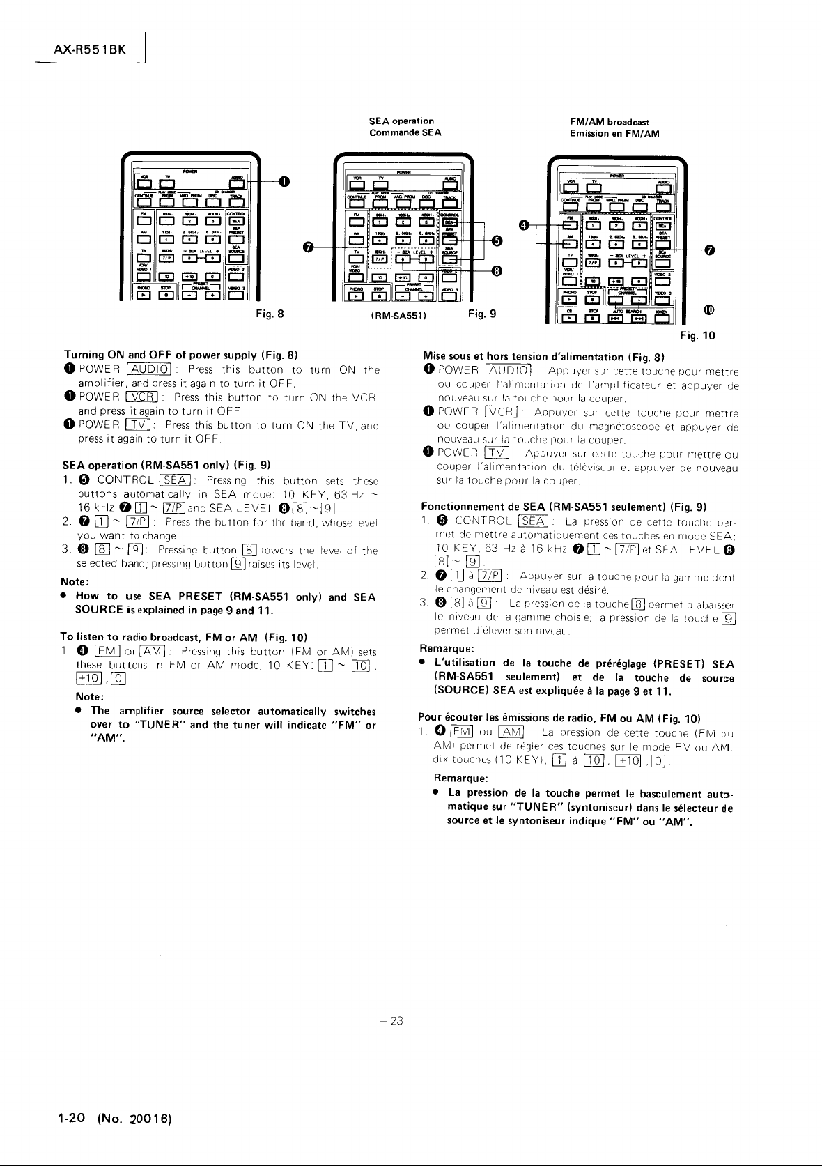
AX-R551
BK
SEA
operation
Commande SEA
FM/AM
Emission
broadcast
en
FM/AM
Turning
o POWER
o POWER
o POWE R
SEA operation (RM-SA551 only) (Fig.
1.
2. 0
3.
Note:
•
To
1. e [fMJor[AMI
ON
and
OFF
of
[AUDIO[
amplifier,
and press
press
Cl)
buttons
16
you
0
selected band; pressing
How
SOURCE
listen
these
[+101 ,[Qj.
Note:
• The amplifier
and
press
[VCR [ Press
it
again
CTIZJ.
it
again
to
turn
CONTROL [ SEA
automatically
kHz
O[}]-[7/P[and
DJ
-
[7/P
want
rn:J -[[]
over
"AM".
[
to change.
Pressing
to
use
SEA PRESET (RM·SA551 only)
is
explained
to
radio broadcast,
buttons
to
"TUNER"
in FM
it
to
Press
Press
source
power supply (Fig. 8)
Press
this
again
to
turn
this
button
turn
it
OFF.
this
button
it
OF
F.
[ Pressing this
in
SEA
mode
SEA
LEVEL
the
button
button
button
in
Pressing
or
and the tuner will indicate
rn:J
lli1
page
9 and 11,
FM
or
AM
this
AM
mode, 10
selector automatically
Fig. 8
button
it
to
OFF.
to
9)
turn
to
turn
ON the
button
10
KEY,
turn
ON the
0[E-ffi]
for
the band, whose level
lowers the level
raises its level.
(Fig. 10)
button
(FM
or
KEY:
[l]
ON the
TV,
sets
63
of
and
AM)
-
switches
"FM"
(RM·SA551)
VCR,
and
these
Hz
-
the
SEA
sets
[IQ]
,
or
Fig. 9
Mise
sous
et
hors
tension d'alimentation (Fig.
o POWE R
ou couper
nOllveau sur
o POWE R
ou
nouveau sur
o POWE R
couper
sur
Fonctionnement
1 0
met de
10
lAUD
10
1
I'alimentation
la
touche
l\Z£;R]:
couper
Lf\/J
I'allmentation
la
touche
CONTROL I SEA I La
mettre
KEY,
63
Appuyer
I'alimentation
la
touche
Appuyer
pour
la
couper.
de
SEA (RM·SA551 seulement) (Fig.
automatiquernent
Hz a
16
ffi]-ffi]
2.
0
DJ
a
[7lP]
le
changement de niveau est desire .
3.
0 [ill a
[]]
le
niveau de
permet
d'
Remarque:
• L'utilisation de
(RM-SA551 seulement) et
(SOURCE) SEA
Pour ecouter
1 0
IFMI
AM)
permet
dix
touches (10
Remarque:
•
La
pression
matique
source
Appuyer
La
pression de
la
gamme choisie,
elever son n iveau.
la
touche
est
expliquee
les
emissions
ou
et
IAMI
(Je
sur
le
La
reg)er
KEY),
de
la
touche permet
"TUNER"
syntoniseur indique
Fig.
10
8)
Appuyer
pour
pour
kHz
ces
sur cette
de
I'amplificateur
la
couper.
sur cette
du magnetoscope et
la
couper.
sur cette touche
du televiseur et appuyer de nouveau
pression de cette
00]
sur
la
touche
la
touche
la
de
pniniglage (PRESET) SEA
de
11
la
de
radio,
pression de cette
touches sur
DJ
a
[JQJ,
(syntoniseur)
touche
et
touche
pour
ces
touches
en
-17/pl
et
SEA
pour
la
[ill permet d'abaisser
presslon de
la
touche
page
9 et 11.
FM
ou
AM
(Fig. 10)
touche
le
mode FM
1+101
,[Q]
le
basculement auto·
dans
ou
le
"AM".
"FM"
pour
appuyer
pour
appuyer
mettre
9)
touche
Illode
LEVEL
gamlTle
la
touche
de
source
(FM
ou
selecteur
mettre
mettre
per-
SEA:
dont
A~1
de
de
ou
0
U'D
ou
de
1-20
(No. :20016)
-
23-
Page 21

2. 0
DJ
~
[IQ]
grammed in
your
of
channel number. Examples
Channels 1
For
For
Channel 17
button
Channel
button
Channel
button
3.
ID>
PRESET
Incrementing
Ing
the
channel
, [±J]J,
the
tuner,
choice, and press the
~
10
Channel 5, press
Channel
17
[IQ]
[§]
Press
IP
I.
20
Press
.
25
Press
.
CHANNEL
or
next
channel above
10,
decrementing the
[]]
numeric
press
[iJ]J
G:IQJ
[iJ]J
Of
check the
button
button
numeric
button
button
button
B
8J
or
below
FM/
AM
Emission
the preset channels, pro-
number
of
the channel
corresponding
to
that
[§J.
button
[IQ]
and then
the
currently
.
then
buttons
That
numeric
numeric
numeric
are
is,
select-
selected
for
once and
once and then
twice
These
number.
broadcast or
en
FM/AM
2.
3. Canal preregle
TV
ou
TV
Fig. 11
f)
DJ
a
[IQ]
,
[±IQ]
,
[QJ.
le
programmes dans
canal selectionne, et
au
numero
de canal. Exemples
a
Canaux 1
Pour Canal 5,
Pour Canal 10,
Canal 17
touche
Canal
touche
Canal
touche
touches sont
Elles
dessus ou au-dessous du canal
10.
Appuyer
numerique
20.
Auuyer
numerique
25.
Appuyer
numerlque
ut,l
permettent
syntoniseur, contr61er
appuyer
appuyer
appuyer
sur
17/pI
sur
sur
sur
la
la
touche
touche
[IQ].
sur
la
touche
ffil
(PRESET
isees
donc
CHANNEL)
pour
augmenter ou
de
selectionner
Pour
les
canaux preregles et
touche
numerique
nUrTerique
une fois, puis
une
une fois, puis
le
correspondant
sur
la
touche
la
la
touche
[±IQ]
0Q]
[±IQ]
ID>
redJ
le
actuelleme~t
canal suivant au-
AX-R551
numero
ill].
[IQ].
fois, puis
BG.
i re
le
numero.
selectionne.
BK
du
la
la
la
Ces
To
listen
to
Turn
1.
0 I
automatically
o
ton.
o I
(TARGET
Notes:
• For remote control or VCR and TV, refer
• These buttons automatically shift
2.
fj
mote
nel.
3.
~
selection
selects
nel.
TV broadcast (Fig.
power
ON in each
TV
I Pressing
ITVI
(TARGET
TV
I.
KEY,
VCR goes
TV
--+
ID>
this
to
TV.
--+
VCR)
goes
into
TV)
PRESET CHANNEL
DJ ~ [[], []] (When
control)
PRESET
the
CHANNE
upward
channel
Press
or
immediately
11)
component
button
(TARGET
into
TV
TV
mode
you
the
button
L
BC±J
downward.
involved.
switches the source selector
--+
AMPLIFIER)
mode
by
by
to
ElG.
select
VCR
for
the
For
Each push
next
to
pressing
pressing this
to
TV mode: 0
or
TV
on
desired
shifting
the channel
of
the
the
current
this
button.
page
the
TV
button
but-
28.
chan-
chan-
10
re-
Pour ecouter les emissions de television (Fig.
-
24-
Appuyer
appareil concerne
1.
2.
3.
sur
la
touche
pour
0 I
TV
I·
La
ment
automatique
source. (Cible
o I
TV
boitier
mangetoscope
scope)
o I
TV
de
telecommande
passe
en
Remarques:
• Pour le
(VCR)
• Ces
TV: dix
SET CHANNEL)
0
DJ
I 'aide du
touche
Canal preregle
decaler
pression de
i m med iatement avant ou apres
pression de cette
sur
--+
Amplificateur)
I Select
de
(TARGET
I·
mode
touches
ionner
telecommande
passe
alors
--+
Selectionner
et
touches
VCR)
et
appuyer
TV.
(Cible
boitier
le televiseur, se rMerer a
de telecommande, le
permettent
(10
GG.
a []],
[QJ
(Lorsque
boitier
pout
la
selection de canal
de telecommande).
le
canal de televiseur desire.
(PRESET
la
touche
pernet
TV.
(TV) a I'a
(TAR:;
la
page
autom,tique
prerigle
ou
TV
ID>
haut ou
u i actuel.
111
dans chaque
le bascule-
(VC
R)
a I
cECte
touche. Le
(Citle
--+
i de du
ET
magnetoscope
IS.
eSI
selectionne
AIPuyer
GG
El
bas.
ner
mettre
I'alimentation
TV
le
le
KEY) 0
touche
(televiseur) dans e selecteur de
(TARGET~AMPLlFIER)
magnetoscope
et appuyer sur
en
mode
televiseur
sur cette touch!_ Le televiseur
--+
televiseur)
le passage
,canal
VCR
CHANNEL)
en
perm et de selectien
cel
'a
ide
magneto-
boitier
--+
TV)
en
mode
ID>
(PRE-
sur
Pour
Chaque
le
canal
du
a
la
(No.
2~O
1 6) 1-21
Page 22

AX-R551 BK
Turntable
Tourne a disque
(RM·SA551)
or
cassette
deck
ou
(TAPE
platine a cassette
,-
-
1)
(TAPE 1)
10
CH:!]
~
wm
i
IES
I m -
,[!]
'mmll
[al
ICb
aoel-[51
mmm
CD CD
[El
II}--[!J
1
lr:::l
[El
11F--.~1
m
lE]
~
="
0
m
Eii3
(RM·SA441)
El
~
CD
-,
§
-~
Gl
""""'"
---
-~I
c::::J-GJ
.~
0,
01
I
01
Fig.
12
CO
player
de
or
disques
Lecteur
magnetophone
OAT
deck
compacts
audionumerique
ou
Fig. 13
To
play
phono
1,
4D
ton
switches the source selector
or
"TAPE 1 ",
playback
Note:
•
4D
switched
2,
4D
phono
To
play CO
4B
or
the
CD
this
button
1+101,
[QJ
1,
4B
mences
Note:
To
•
2 terminal, press
G}
2,
fJ
formance,
3,
AUTO
the selection being played and returns
selection,
AUTO
the
selection,
Note:
• Press once
forward,
or cassette deck (Fig. 12)
PHONO
or
CD
or
music
CB
or
Q)
TAPE
depending
starts
PHONO 0 (RM·SA441 only): Source selector
to
"PHONO".
® STOP m
or
cassette deck,
or
OAT (Fig. 13)
41)
10
KEY
0
or
a program
first and
buttons
for
~
or
G}
play
back,
listen
to
music with a OAT deck
OAT
[El
button.
49
STOP
rn,
SEARCH
SEARCH
(I ~ I),
(I
and
brings
to
advance
keep pressing this
on
Pressing
To
select a
by
the
number
then
press
the 0 10
the selected number,
OAT
~
411
TAPE 2
Press
Pressing
~
I)
Pressing this
the
CD
or
to
the
button.
1
[EJ
automatically
the
button
th
is
button
track
on
the
Pressing
connected
button
this
button
this
to
tape
to
the start
next
selection. For fast
Pressing the
to
"PHONO"
you
press, and
stops the
by
number
OAT
deck,
KEY
DJ
~
th
is
button
to
first
and
to
stop the per-
button
interrupts
the start
button
interrupts
of
the
but·
press
0]],
com·
TAPE
press
of
that
next
on
Pour effectuer
cassettes (F
1,
4D
cette
"PHONO"
le
cholx
is
Note:
•
4D
selecteur de source passe en
4D
2
permet
El
cassettes,
Pour
effectuer
phone
audionumerique
fJ ou
une piste selon
me
selon
appuyer
10
KEY
1
fJ Disque
audionumerique
permet
Remarque:
• Pour
numerique raccorde
sur
audionumerique
2,
fJ ou
arreter
3, Recherche
pression de cette
du morceau
la
selection,
Recherche
pression de cette
morceau et d'amener
debut
Remarque:
Appuyer
•
cer
cement
la
lecture de tourne-disque ou de
ig.
12)
PHONO
ou
~
ou
Q)
TAPE
1
touche
G}
d'abord
DJ
la
de
la
permet
ou
"TAPE
et
la
lecture commence,
PHONO D (RM-SA441 seulement):
Q)
STOP
d'arreter
la
lecture
dix
touches (10
le
numero
le
numero de magnetophone
sur cette
El
[IQ] ,
compact
de commencer
ecouter
touche
49
STOP
la
lecture,
automatique
en
cours de lecture et de
automatique
la
selection suivante,
sur
bande a la
rapide,
le
1"
dans
~
la
lecture du
de
disque
de disque
touche,
[tJ]J
,[QJ
(CD) D ou
(OAT)
[EJ,
la
lecture,
un morceau a I'aide de I'enregistreur audio-
a
la
borne
411
TAPE 2, puis sur
( OAT)
[El
00
(AUTO
touche
permet
(AUTO
touche
permet
le
disque
la
touche
une fois
selection suivante. Pour
continuer a appuyer
[E]
basculement
le
selecteur de source selon
mode
PHONO.
La
pression de cette
tourne·dlsque
compact
KEY)
0 Pour selectionner
compact
PUIS
pour
le
La
pression de cette
TAPE 2,
.
Appuyer
sur cette
SEARCH)
d'interrompre
retourner
SEARCH)
d'interrompre
compact
de
La
autornatique
Le
ou de
ou du magneto-
ou un program-
audionumeriqu
sur
les
numero
plus
selectionne,
49
magnetophone
appuyer
49
magnetophol1e
touche
(I~I)'
au
(L~)'
la
ou
la
pour
effectuer
sur
cette
la
platine a
pression de
touches 6
mode
touche
la
plat:ne
toucne
d'
abord
pour
la
selecti{)n
debut
lecture de
bande a u
faire avarl-
I'avarl-
touche.
sur
du
e,
La
de
La
1-22 (No.
20016)
-
25-
Page 23

CD
AUTO
CHANGER
f)PLAY
8CD
SURROUND
This
ed
button
4fIIMODE]:
4fISURROUND
CDAUTO
Lecteur/changer
MODE
ICONTINUE
magazine sequentially, starting
the program.
IPRGM
med sequence
IMAG.
button.
this
programmed in
Function
CD
players
changer.
CHANGER
Pressing
use
in CD changing.
IDIScl
its
number
button
ITRACKI
by its
TRACK
Notes:
• To understand 10
• For detail, consult the instruction book of the
changer.
control
to
TAPE 2
Cl
sor's selector
the
output
order
lowers and pressing
Note:
• For detail, consult the instruction book of the surround
processor.
I:
I:
Press
PR
GM
of
MAG
then
DISK
+
.,
in
before
+
.,
number
button
CONTROL
is
for
terminal.
first
and then the
Press
from
levels
to
enhance the
CHANGER
de
operation (Fig. 14)
Pressing
this
I:
the
the
or
10
KEY:
the
operating 10 key
10
in the magazine. In the
before operating
the
this
VOLUME
disques compacts
this
button
button
to
Set
your
discs
magazine.
PRGM
consult
TRACK
magazine. In the
KEY:
surround processor
its
magazine in place and press
will
be
played back in the sequence
isn't
operated in the
instruction
button
Press
this
function.
Press
KEY
operation, refer
(Fig. 15)
For
surround
following
button
to
current
mode
BG:
of
the
front
surround
GJbutton
raises the volume.
with
play
this
10
shift
and
effect.
plays the discs in
Disc 1, regardless
the
discs in program-
case
book
of
CD
assigns"
kay
case,
key
key
control,
the
to
another.
For
surround
SURROUND
Commande d'audiophonie
10
to
specify a disc
press 0 DISC
to
specify a
case,
function.
to
page
(optional)
press
surround proces
raising
or
speakers, in
Pressing G
CONTROL
KEY
press 0
14.
CD
connect-
lowering
of
some
auto
track
auto
TAPE
button
the
of
for
by
Fonctionnement
du
lecteur/changeur
de
disques
AX-R551
compacts
BK
(Fig. 14)
8 Mode
@)
2
Commande d'ambiophonie
de
I
CONTINUE
ture
commen<;ant par
programme.
I
PRGMI:
ture
I
MAG.
cette
quence programmee dans
Certains modeles
PRGM.
lecteur/changeur de disques compacts.
Changeur
La
permet d'assigner
utilisation
lecture
sequentielle de disques compacts dans le chargeur,
de disques selon
PRGM
touche:
Se
pression de
I DISC I +
specifier un disque par son
cas,
appuyer
touches
I
pour
En
sur
Remarques:
• Pour
• Pour
(10
TRACK
I +
specifler une piste par son
ce
cas,
les
dix
le
reterer a
plus
du
lecteur/changeur
(PLAY
I:
La
Appuyer
I:
la
reporter
de
disques
la
lors du changement de disques compacts
f)
10
d'abord
KEY).
f)
10
appuyer
touches (10
fonctionnement
la
page
de
details, consulter
MODE)
pression de cette
le
disque (Disc) 1
sur cette
la
Mette
lecture de disques
ne
sont
donc
compacts (CD
touche
les
KEY:
sur
KEY
dabord sur
14.
touche
sequence programmee.
le
chargeur
le
chargeur.
pas
munis
au
manuel
disque
touches
Appuyer
numero
la
touche
:
des
disques
(DISK)
Appuyer
numero
la
dix touches
compacts.
dix
KEY).
de
(SURROUND
touche
perm et
independamment
pour
effectuer
en
place et
commence
de
la
fonction
d'instruction
CHANGER)
ou
piste
(10
KEY)
sur cette
dans
le
chargeur.
0 DISC, puis sur
sur
cette
dans
touche 0 TRACK,
(10
le
manuel d'instructions
CONTROL)
appuyer
selon
(TRACK)
.,
touche
le
chargeur.
KEY),
la
lec-
du
la
lec-
sur
la
se-
MAG.
pour
pour
pour
En
ce
les
dix
touche
puis
se
le
(Fig. 15)
Cette
commande
(optionnel)
commande
TAPE
2
Cl
4111
MODE
actuel du selecteur
411
Volume d'ambiophonie
Cette
touche
de sortie des haut-parleurs avant et
relever
permet d'abaisser
touche
Remarque:
• Pour plus
du
processeur
est utilisee
raccorde
d'ambiophonie,
,puis
la
suivante:
I:
Appuyer
est utilisee
I'effet
d'ambiophonie.
[iJ
permet
de I'elever.
de
details, consulter
d'ambiophonie.
El
la
borne
sur cette
du
processeur
(SURROUND
pour
le
volume,
pour
le
processeur
TAPE
appuyer
d'abord
touche
d'ambiophollie
elever ou abaisser
La
pression de
alors que
le
d'ambiophonie
2. Pour
pour
effectuer
sur
la
decaler le
touche
mode
a un autre.
VOLUME)
d'ambiophonie
la
manuel d'instructions
Bm:
les
niveaux
afin
la
touche
pression de
la
de
B
la
Fig.
14, 15
-
26-
(No.
20016)
1-23
Page 24

AX-R551 BK
Control
without
fier.
See
1.
4El
button
serve
ti>
2.
or
3.
ti>
DAT
4.
ti>
cassette
ti>
recording
ti>
5.
winding
41>
winding
ti>
while
ti>
tons,
operation.
Notes:
* By
"TAPE
(named
TAPE
* *
To
of
4El
Note:
• I n
CONTROL
Commande
du
4D
~
the
COMPU
changing
the
Note**. (Fig. 16)
CONTROL
or
I OAT I
the
cassette
PLAY
DA
the
~:
T deck
STOP
00:
deck
to
PAUSE/STILL
or
OAT
PLAY
[E]:
operation
~:
into
~:
REC
REC
operating
play
the
lOA
the
into
the
[ill
keeping
[ill
ill]
and
(Record
2"
of
"TAPE
2,
press its
the
OAT
amplifier. Press
T 1 and
case
of
TAPE 1 or
du
magnetophone
[d]
m
[!J
1-'
mll
~[
='D
[IT:!
m
GJ8
~ff
II~~
..lYe
LINK
the
"SOURCE
CfAPE=:l
button
deck
or
Pressing this
for
playback.
Pressing
interrupt
the
OAT
magnetophone 1 ou
audionumerique
"""""""
El El
~
-
....
~--I
D--GJ
£Eii3
,.."./
.........
mmm
ElCElEl
I
""""
_SAMl
R)II,t,X-_,
\"*1EII N
REMOTE
cassette
SE
or I OAT
makes
the
OAT
this
button
playback.
[!!] : Pressing this
deck
in
play
that
cassette
~
at
the
can
be
control
will
not
connect
the
the
deck,
back
has been
button
reel.
button
reel.
: Pressing
pressed
same
resumed
But
start
41)
button ~ .
some
Pressing this
Pressing this
left
cassette
Pressing this
right
+
PLAY
[ill
button
+
PAUSE/STILL
OIl
ing
the
remote
the
amplifier.
2")
PLA Y button.
deck,
operate
cassette
01
DI
01
UMC
+
I11
camIOt.
"'"
deck
LECTOR"
I:
the
deck,
button
operation.
button
interrupted
sets
sets
commences
[]I]:
time
at
unit,
the
playing.
it
to
the
TAPE
aren't
,
Fig. 16
and
"OAT
of
the
Pressing
control
respectively.
starts
stops
button
the
the
button
the
the
cassette
pauses
resumes
by pause.
tape
tape
[JB~EJ
cilssette
in
in
[E]
Pressing
pauses
any
you
activated.
recording.
these
the
recording
time. )
can
select
cassette
TAPE 2 terminals
To
2 D
recorder
play
button,
deck"
ampli·
ti>
the
the
rapid
rapid
button
but-
the
the
or
Regler
la
audionumerique
selecteur
marque
1.
2.
3.
4.
5.
Remarques:
*
faire
* *
Remarque:
•
Certaines
platine
de
**.
(Fig. 16)
4El
Commande
audionumerique
pression
magnetophone
la
I'enregistreur
ti>
permet
registreur
ti>
permet
ou
lecture.
ti>
cette
la
ti>
commencer
touche
~
ment
ti>
ment
41>
ment,
presser
~
soirement
[i!]
mence
En
selectionner
teur.
tophone 2 (TAPE
la
Pou
(OAT),
(TAPE
41)
de
touche
Lecture
de
Arret
d'arreter
de
I'enregistreur
Pause/fixe
touche
plallne
PLAY~:
d'arret
L~:J:
rapide
L~
rapide de
REC [QJ+
appuyer
la
REC
[QJ
en
au
utilisant
Toutefois,
fonctionner
touche
de
r faire
raccorder
2)
Magnetophone
platines
iI
cassettes
(OAT
deck)
source
(SOURCE
du
magnetophone 1 ou
(CONTROL
la
touche
de
magnetophone I TAPE
audionumerique
de
commande
audionumerique
(PLAY)
faire
fonctionner
audionumerique
(STOP)
le
(PAUSE/STILL)
permet
cl
cassettes
I'enregistrement
provisoire.
La pression
de
la
I:
La
pression
la
PLAY[EJ:
sur
touche[Q].
+
PAUSE/STlLL[}[]:
I'enregistrement,
me me
temps.
moment
le
boltier
le
Magnetophone 2 (TAPE
I'enregistreur
le
lecture
fonctionner
de
I'amplificateur.
ti>
[EJ:
~:
fonctionnement
audionumer'lque
d'arreter
ou
de
La
pression
de
bande
dans
de
bande
dans
la
touche
(L'enregistrement
desire.)
de
telecommande,
2)")
ne
Magnetophone 2 (TAPE
(PLAY).
le
celui-ci
20,
ii
cassettes
COMPU
sans
LINK
changer
SELECTOR).
[TAPE
LQAfJ
pour
la
platine a cassettes
respectivement.
La
pression
la
platine a cassettes
pour
commencer
La
pression de
de
[If]
provisoirement
I'enregistreur
de
cette
qui a
ete
cette
touche
la
bobine
cette
touche
la
bobine
Pour
commencer
~
tout
appuyer
se
magnetophone
aux
4El1
ne
sur
de
cassette
met
pas
bornes
Appuyer
OAT
I,
fonctionnent
et
I'enregistreur
I'amplificateur
Voir
du
magnetophone
J ou
[Q@):
permet
de
cette
la
cette
la
platine
pour
'Interrompre
:
La
presslon
la
audionumEmque.
touche
permet
interrompu
permet
gauche
de
permet
droite
de cassette.
I'enregistre-
en
continua1t
Pour
arreter
les
touches
peut
et
il
est
possible
2)
de
I'amplifica-
(designe
iI
fonctionner,
21.
appuyer
audionumeriq
de
Magnetophone
sur
les
touches
puis
la
touche ~ .
pas.
la Re-
1 DU de
d'utiliser
touche
DU
de
I'en-
lecture.
touche
El
cassettes
lecture
de
par
I'
enrou
cassette.
I'
enrou
provi-
[Q]
re recom-
"Maine-
Po
du
La
DU
la
de
de
re-
la
le-
le-
a
et
de
ur
sur
ue
2
du
1-24
-- 27 -
(No. 20016)
Page 25

AX-R551
BK
VCR
Magnetoscope
El
ii:i'''ffi
[El
!El
El
II][=]
Video
cassette recorder playback (Fig.
1. 0
VCR/VIDEO
the source selector over
2.
0
VCR/VIDEO
switching
VCR.
1 0 : Pressing this
automatically
1 D (TARGET
the
TV's
"INPUT
SELECT"
Notes:
is
set
to
the
• When the VCR
fast forward, rewind or
mode, selecting the VIDEO signals from the
OUT
terminals (for VIDEO) may cause black and
stripes
on
TV
screen.
book
of
• Consult instruction
the
ponents.
3.
~
PLAY
~
ton sets
(TARGET
the
VCR in playback operation.
-->
VCR): Pressing this but-
Notes:
•
In
this case,
wish
to
• It takes a
the
on-going play
stop, take the action required.
few
seconds for a pictures
screen.
4.
ID
STOP
[jJ
5.
(TARGET
ID>
PRESET CHANNEL B -
For
switching
ward.
How
to
the
1.
2.
control
amplifier's source selector (Fig.
lE)
CONTROL I VCR
control
ID
PLAY
ton starts
the VCR tuner's channel
the
VCR
button ~ serve the VCR.
~
(TARGET
the
VCR in playback.
-->
without
I:
Pressing this
-->
VCR):
CB
making any selection with
17)
VCR): Pressing this
m
17)
button
to
VCR.
-->
TV): This
to
VIDEO
TV
corresponding com-
is
not
stopped. If
to
appear
For
stopping VCR.
(TARGET
upward
button
-->
or
makes the
Fig. 17
switches
is
1 or
stop
LINE
white
you
on
TV
VCR):
down-
but·
for
In the
case
of
IT
ARG
ET
-->
TV)
or
(T
ARG
ET
-->
per end
of
remote
control
unit
then operate remote
Lorsque (Cible
scope)
(TARGET
superieure du
-->
TV)
-->
bOltier
control.
VCR)
Lecture de magnlltoscope (VCR) (Fig.
1 0 Magnetoscope/video (VCR/VIDEO) 1
si
on
de
cette touche perm et le basculement
sur
le
magnetoscope
2.
0 Magnetoscope/video (VCR/VIDEO) 1 D (Cible
Televiseur) (TARGET
permet le basculement
ou
magnetoscope
SE
LECT) du televiseur.
(VCR)
at remote sensor
IT
ARGET
de telecommande vers le detecteur.
est
-+
TV)
indique,
17)
(VCR)
dans
le
selecteurde
-+
TV):
La
pression
automatique
dans
la
selection
VCR) level upof
ou (Cible
diriger
D:
de
du video 1
dentree
automatique
cette touche
Remarques:
est
• Lorsque le magnetoscope
de
rapide,
rebobinage ou d'arret
dans le
les signaux VIDEO des prises de sortie
LINE OUT) du televiseur (pur
que
sible
des bandes noires
et
blanches aj)paraissent sur
et
que
la
VIDEO),
node
I'on selectionne
de
I'ecran TV.
• Se reporter
au
manuel d'instructions
,our
concerne.
3.
~
Lecture (PLAY) [EJ (Cible
-->
GET
placerle magnetoscope dans
VCR):
La
pression de cette
-->
Magnet~scope)
le
mode de lecture.
toU(he
Remarques:
•
En
ce
cas,
la
desire, donner
11
faut quelques secondes
•
lecture en cours ne s'arrete pIS. Si I'arret
la
commande
necessaire_
cl
!'image
pourapparaitre
I'ecran TV.
4.
~
Arret (STOP)
-->
VCR): Pour arreter le magnetoscope.
5.
4D
Canal preregle (PRESET CHANNEL)
-->
Magnetoscope) (TARGET
canal
de
syntoniseur de magnetoscope
Commande du
avec le selecteur
1.
4El
Commande de
La
pression de cette touche permet
commande
2.
4P>
Lecture (PLAY) [EJ (Cible
GET
-+
lecture
VCR):
du
~
(Cible -+
-->
magnetoscope
de
source de I'amplificateur (Fil.
sans effectuer
magnetoscope
4i)
pour
le
magngetoscope.
La
magnetoscope.
pression de cette
Magnetosc~~e)
[]
VCR):
en
-
POL
commuter
haL:
ou
a~~Llne
17)
(CONTROl I VCR
d'util
iSt'
la
-->
Magnet~5c:ope)
touhe
TV
or
VCR
-->
Magneto·
I'extremite
La
pres-
source.
(VIDEO
(I
NPUT
d'avance
ligne (TV
il
est
pos-
I'appareil
(TAR-
perm et de
(TARGET
CB
Cible
en
bas.
selection
I):
touche de
(TAR-
permet
-->
1)
est
sur
le
la
-
28-
(No.2~016)
1-25
Page 26

AX-R551 BK
Notes:
•
In
wish
•
When
2"
If a
tape
button,
•
When
terminals,
To
CONTROL
•
When
nal,
3.
41>
STOP
VCR.
4.
41>
PAUSE/STILL
this
button
toSTILL.
41>
PLAY
ton
resumes
rupted
5.
41>
I
.... I (TARGET
wind
the
41>
I
~
the
tape
PLA Y mode,
the
"SHUTTLE
41>
REC
start
recording,
ton
pressed.
41>
REC
Pressing
pauses
at
any
Switch
the
(connected
01vIDE021
the
Amplifier
01vIDEO
SELECT"
"VIDE03".
ACOUSTIC
CD
I
ACOUSTIC
ACOUST
again,
volume
Move
W
VOLUME
increased
Mute
the
W
FADE
each
time
this
case,
the
to
stop
selecting
terminals,
cassette
playback
press
playing a DAT
start,
press
connecting
do
not
00
on-going
it,
take
the
the
component
press
the
deck
is
connected
cannot
the
PLAY
and
connect
the
TAPE 2 button
button.
the
connect
cassette
the
(TARGET ~ VCR):
[iIJ
while
the
VCR
~
(TARGET ~ VCR):
the
recording
by
pause.
tape.
I
(TARGET
in
rapid
forward
these
two
SEARCH".
[Q] +
PLAY
press
~
[ill
+
these
the
time.)
audio
tothe
210r
the
sound
MUTING
PAUSE/STILL[JI]
buttons,
recording
and
TV
or
IVIDE031:
selects
[ill
operation.
video
set). (Fig.
the
"TV".
l.SLtQfQjJ
of
the
TV
EXPANDER
EXPANDER
I C EXPAN
ACOUSTIC
up
or
1-
or
decreased
(Fig.18)
this
button
I
Efl
1-'
CEJ
[01
ICb
~-'~-~
~
GJ
effects
DE R effects.
EXPANDER
down
(Fig.
11
gradually.
~:
is
pressed.
m rE5B
.-
mll
--
--~I
="
Cl
lEiiEl
ffi
~[]J,=m
IEI
Gl
I - + I
--
play
is
action
TAPE 2 button.
be
started
button
deck,
the
remote
remote
(TARGET ~ VCR):
is
in
operation
VCR):
VCR):
motion.
buttons
[El
button
and
signals
17)
The
(TARGET ~ TV):
set
selects
(Fig.
I:
Press this
18)
The
01
Cl
D--£:I]
not
required.
connected
to
these
with
the
of
the
connect
(TARGET ~ VCR):
+
it
to
cable.
then
deck
to
the
cable.
For
playback
(Recording
from
I:
volume
switches
Pressing
that
Press
this
Press
this
When
the
can
be
used
while
keeping
(TARGET ~ VCR):
[i!J
,
at
the
video
"SOUND
the
18)
button
Pressing th
effects
The
sound
is
further
m.
-:-
01
CEJ
8
......
I
stopped_
terminals,
remote
has
If
to
the
"TAPE
control
cassette
the
"TAPE
press
the
TAPE 2 termi-
stopping
Pressing
its
this
been
button
button
to
tape
is
irr
for
selecting
[QJ but-
the
same
can
be
resumed
equipment
SELECT"
The
"INPUT
"VIDEO
2"
to
engage
is
button
are by-passed.
volume
decreased
Fig.
18
you
since
deck.
2"
DA T
the
mode
but-
inter-
to
re
set
the
To
time
of
or
Remarques:
• En
ce
cas, la
lecture
en
cours
ne
s'arrete
pas. Si
I'arret
desire,
donner
la
commande
•
Pour
selectionner
2",
appuyer
Si
une
comme
avec la
PLA Y de
•
Pour
"TAPE
Pour
appuyer
• Lors
TAPE
3. ~ Arret
~
VCR):
4.
41>
Magnetoscope)
d'arret
cours
~
GET
commencer
mode
5.
41>
Appuyer
~
ApPllyer
rapide
(PLAY),
tionner
SEARCH)
~
~
Magnetoscope)
I'enregistrement,
nuant
~
(PAUSE/STILL)
~
VCR):
[]I]
(L'enregistrement
desire)
Basculement
(raccorde
{1)
[VIDEO
is
(SOUND
ner
o
[S7I5EQ)]
Le
mode
seur
"VIDEO
Effets
(Fig.
18)
d1I
Expanseur
Appuyer
effets
Augmentation
W
Volume
augrnente
Diminution
W
Silencieux
dlrninue
est
platine a cassette
la
touche
la
utiliser
2",
commencer,
sur la
du
raccordement
2,
ne
(STOP) ~ (Cible ~ Magnetoscope)
Pour
Pause/arret
sur image (STI LL),
de
la
lecture
Lecture
-+
VCR):
I'enregistrement
d'arret
1
...
1 (Cible ~ Magnetoscope)
sur
cette
~
(Cible ~ Magnetoscope)
sur
Lorsque
ces
deux
le
mode
Enregistrement
a presser
Enregistrement
La
permet d 'arreter
des
au televiseur) (Fig.
21
ou
SELECT)
le
mode
de
ou I VIDEO
de
selection
perrnet
3".
d'expanseur
acoustique I ACOUSTIC
de
d'expanseur
et
C::=::==:=J
ou
dim i nue
de
volume
en
par paliers a chaqLle prcssion
I'appareil
sur
la
touche
lecture
de
de
telecommande,
platine a cassette.
une
platine
puis
la
raccorder
appuyer
touche
pas
raccorder
arreter
sur
image
(TARGET ~ VCR):
du
(PLAY)
provisoire
cette
magnetoscope
CB (Cible
La
pression
touche
touche
la
bande
touches
de
(REC)
(TARGET ~ VCR):
applJyer
la
touche
(REC)
DIJ
(Cible ~ Magnetoscope)
presslon
peut
signaux
[YfDE([3]:
de
televiseur
d'entree
de
selectionner
acoustique
nouveau
acoustique
diminution
I + I:
graduellemen1.
par
fondu
(FADE
necessaire.
raccorde
TAPE
est
la
bande
DAT, la
sur
DAT
CONTROL.
de
la
platine a cassettes
le
cable
le
magnetoscope.
(PAUSE/STI
appuyer
de
cette
qui a
(PAUSE)
pour
rebobiner
pour
est
peuvent
recherche a navette
[Q]+
sur
la
aux
2.
raccordee
ne
peut
appuyer
raccorder
au
cable
de
la
touche
de
telecommande.
LL)
Pour
sur
~
Magnetoscope)
touche
ete
interrompu
(TARGET ~ VCR):
la
(TARGET
mettre
la
dans
le
mode
etre
utilisees
lecture
(PLAY)
touche
~
[QJ
[Q]
+
pause/arret
simultanre
provisoi
etre
audio
17)
I'amplificateur
(TV)
31
(Cible ~ teh!viseur):
(ACOUSTIC
sur
cette
de
paliers
de
ces
rement I 'enregistremen
recommence
et
video
de
Le
mode
de
perm
(INPUT
(ACOUSTIC
volume
(Fig.18)
MUTING)
le
modE
EXPANDER
touche
(Fig.
Le
SELECT)
EXPANDER)
18)
volume
~:
de
bornes
aces
pas
etre
sur
aux
telecommande.
TAPE
[!iJ
passer au
cette
permet
bande.
-+
bande
(SHUTTLE
Pour
commencer
tout
touches
au
I'appareil
selection
et
de
"VIDEO
pour
ignorer
EXPANDER)
de
cette
est
"TAPE
bornes,
lancee
la
touche
bornes
2,
puis
a la
borne
(TARGET
(Cible
mode
touche
(TAR-
de
re·
dans
VCR):
en
avance
de
lecLl re
pour
Sei8C-
[EJ
(Ci~le
en
conti-
sur
image
(TARGET
[QJ
moment
audio
de
SDn
selection-
du
televi-
2"
:>u
I :
es
son
'st
Le vollll) e
tOLlcile
~
au
le
et
t.
1-26 (No. 20016)
-
29-
Page 27

AX-R551
BK
r"'AJlDI' •
.. " •••
rv
Ill/
Remote
Control
,&IV
•••••
1111
System
,
COMPU LINK REMOTE CONTROL
SYSTEM
The COMPU
developed by JVC.
ponent
following
Automatic
If
the attached remote cable
other
terminals, sources
unit's source selector
ponent
ton
of
activation
When
cassette
will stop playing after
Synchronized recording
Synchronized recording refers
sette deck
nization
Set
the cassette deck
the procedures in the
When
button
The cassette deck enters the record mode the
player starts and synchronized recording commences.
Synchronized recording stops
player stops playing
To cancel synchronized recording, push the STOP
the CD player,
Notes:
•
When
ing
nized recording
cassette
• Abnormal operation will result
of the components
recording.
to restart.
Ensure
•
each
cable_
component
• The
synchronized recording
ing
synchronized recording.
CAUTION:
•
When
to the TAPE 2 terminals
the
component with a remote
• Connect the remote cable
LlNK-1/SYNCHRO
LINK
REMOTE
You
can
from
the remote
advanced operations
source
selection
JVC
components
can
will
start
to
the remote
button
switching
(jeck,
automatically
with
synchronously recording
on
the
the REC/PAUSE mode
the REC
deck's instruction manual.
that the
component
Be
source
to another source. To
a component
SYNCHRO
play
control
may also
from
turntable
the CD player
CD player.
turntable
and
is
If
this
sure
to
very
carefully.
is
locked to CO or PHONO position during
terminals
control
control
with
be
switched
buttons
automatically.
unit
be
one
component
or
CD player, the previous
about
five
commences recording, in synchro-
or
to
the REC/PAUSE mode according
instruction
or
cassette deck.
PLAY
buttons simultaneously, synchro-
not possible. For details, refer
is
interrupted during synchronized
happens.,
COMPU
is
connected with the attached remote
read
the instruction manual
to
(such
cable_
terminals
CONTROL
each
unit,
with
ease.
is
used
to
COMPU
with
and the corresponding com-
or
the
appropriate
used.
seconds.
to
the process whereby a
turntable.
manual.
the
CD player, push the
automatically
is
set
to PAUSE after
if
the power supply
push
the activation button
LlNK-1/SYNCHRO
avoid accidental
change
the source, first
as a cassette
of
the amplifier, do not connect
of
such
component to any other
of a OAT
of
this
SYSTEM
COMPU
and also
connect this
LINK-l/SYNCHRO
just one touch
The source select
to
unit.
LINK
perform
component's
another, such
component
moment
when
button
terminal of
for
stops
or chang-
deck)
is
connected
to the
was
com-
the
unit
to
of
the
but-
as
cas-
to
PLAY
the
CD
the
CD
of
depress-
to
your
of
one
again
each
cancel
COMPU
SYSTEME
DE
TELECOMMANDE
COMPU LINK
Le
COMPU
developpe par JVC. Vous pouvez non seulement
chaque appareil COMPU LI N K a
commande, mais
suivantes avec aisance.
Selection automatique
Si
le
cet apparei I
LlNK-l/SYNCHRO,
seulement un
de
cet appareil et I'appareil correspondant commencera a lire
automatiquement,
de telecommande ou
concerne peur
d'un
tourne-disque ou
precedent s'arretera
Enregistrement synchronise
L'enregistrement synchronise
a
platine a cassette commence
synchronisation
tourne-disque.
Placer
suivant
Pour synchroniser I'enregistrement
compact,
compact.
La
platine
moment
registrement synchronise commence
L'enregistrement synchronise s'arrete
le
lecteur
Pour annuler I'enregistrement synchronise,
touche STOP du lecteur
ou
de
Remarques:
Si
•
sur
PLA
pas
structions
• Un fonctionnement anormal
de
ment synchronise.
touche d'activation pour repartir.
• S'assurer que
chaque appareil
mande fixe.
Bien lire
La
•
pendant I'enregistrement synchronise pour
accidentels
source, annuler d'abord I'enregistrement
ATTENTION:
•
Si
aux bornes TAPE 2
bornes
avec
• Raccorder
audionumerique aux bornes
30-
de
-
LINK
REMOTE
aussi
cable
de
telecommande attache est utilise
de
a d'autres appareils
les
effleurement
La
touche
aussi
appareil a un autre,
la
platine
les
methodes decrites dans
appuyer
etre utilisee.
le
lecteur de disque
de
avec
le
a cassette en mode de pause/enregistrement en
sur
la
a cassette entre dans
ou le lecteur
de
disque
compact
la
platine a cassette.
le
mode
de
PAUSE
Y simultanement, I"enregistrement sYlchronise n'est
possible. Pour
I'un
source
un appareil (comme une platine a cassettl)
un cable de telecommande.
cet appareil.
pause/enregistrement
apres
avoir appuye
de
des
le
SYNCHRO
les
votre platine a cassette.
appareils
Si
la
borne
est
manuel d'instruction
est
verrouilhie a
ou
des
changements
de
d'un tel appareil
le
cable
CONTROL
partir
effectuer
source
sources peuvent etre commutees avec
des
la
touche
lire qu'apres environ
lecteur
touche
de
de
details,
est
cela
raccordee
I'amplificateur,
de
les
JVC
touches du selecteur de source
de
selection de source du
d'activation
En
comme
se
rapporte
automatiquement
de
avec
PLAY
le
mode d'enregistrement
disque compact demarre et I'en-
s'arrete
de
disque· compact,
se
se
produira
interrompue
arrive, appuyer a Ilouveau
COMPU
avec
de
la
position
de
telecommande
COMPU-LlN~-1/SYNCHRO
SYSTEM
commander
du
bo1tier de tele-
operations
avec
des
faisant
la
platine a cassette,
compact,
au
de
pour
raccorder
bornes COMPU
de
I'appareil
les
commutation
I'arpareil
cinq
secondes.
traitement
a enregistrer en
disque
compact
le
manuel
d'instructions.
le
lecteur
de
sur
le
lecteur
de
automatiquement
lire.
appuyer
du
tourne-disque
est
obtelU
en
sur
les
reporter
pendlllt
LlNK-1/lYNCHRO
le
cabl~
chaque alpareil.
source. PC)tH changer
syncil
ne
avec
les
du
appuyant
tOllc::hes R EC
au
manuel d'in-
si
I"alimentation
I'enregistre-
de
tehicom-
Cl>
ou
eliter
PIS raccorder
PHONO
des
ronise.
est
raccorde
,LJ
tres appareils
rwagnetophone
boltier
arrtHes
a ete
pointe
oll
ou
disque
disque
au
quand
sur
et
sur
de
les
le
la
le
la
la
la
(No.
2(016)
1-27
Page 28

AX-R551
BK
OPERATION OF THE S.E.A. GRAPHIC
EQUALIZER
Compensation for room
The
frequency
on the
listener in
provides
responses,
reflection,
The S.E.A. system
of a room
degree
having a high degree
The
tion"
the corresponding frequency band. Since conventional 'tone
control
around
incomplete. The
separate
the necessary adjustments in the precisely
quency bands in
of a room
Operation
S.E.A, pattern memory
For
use
patterns.
PROGRAMED
These
suggested settings
preset
you
However, since
stored
HEAVY
Used
frequencies are emphasized
ful
and
CLEAR
For
middle
and the
component
room's
the
the
as
echo, and absorption affecting each frequency.
flat
of
absorption
frequency
are
narrow;
systems
the
frequency
audio
and
your
own
the
10
five
S.
E.A. patterns were preset
pattern
can
further
pattern
(PROGRAMED
for
music
sound. Higher frequencies are also emphasized
bring
clarity
(PROGRAMED
crisp,
clear sound
frequencies
middle
of
(AX-R551
response
listener
a result
by
frequency bands, thus
any listening position in
sound compensation and processing, you can
PROGRAMED
is
will
and high frequencies
the music are emphasized.
acoustics
of
shape, furnishings, and
room.
Each
with a different
of
can
function
emphasizing those frequencies having a high
and de-emphasizing those frequencies
of
reflection.
range affected
therefore,
simply
adjust the highs and lows centered
off 1 kHz,
AX-R551
order
to
compensate
for
various types
shown below,
change
each
they
are representative patterns, the original,
be
unchanged.
with
a heavy beat, such
to
the highs, including the percussive notes.
with
that
tend
BK only)
the listening area varies depending
listening
different
by
it
is
only
BK
monitors
and
After
frequency band
Al
Fig. 22
to
produce a deeper, more power-
BI Fig, 23
transparent highs. The
to
be
the
position
position
set
degrees
to
make the sound response
"absorption"
they
MANUAL
unclear are de-emphasized,
of
necessary
are
both
and equalizes seven
allowing
appropriate
for
the acoustic response
it.
at
the
factory
of
audio
programs. Each
recalling these patterns,
to
as
rock music.
that
strengthen the vocal
of
in the
of
frequency
reverberation,
and
"reflec-
to
compensate
imprecise and
you
to
preset S.E.A.
to
suit yourself.
to
enhance
low
room
make
offer
the
fre-
Low
and
FONCTIONNEMENT
DE
L'EGALlSEUR GRAPHIQUE S.E.A.
(AX-R551
Compensation
La
forme
piece. Chaque position d'ecoute dans
teur
resultat
et absorption
Le
reponse sonore
ayant un
ont
Les
reflexion"
la
gamme
Du
n'ajuste que
frequence 1 kHz, elles sont toutes deux imprecises et incompletes.
Le
audio
necessaires dans
avec precision,
d'une
Fonctionnement
Memoire
Pour
disposez
MANUAL.
PROGRAMED
Ces
suggestion quant aux divers types
Chaque forme prereglee est indiquee ci-dessous. Apres
rappele
gamme
sont
ne
sera
HEAVY
Utilisee
rock.
son plus
aussi
clarte aux hautes. Y compris
CLEAR
Pour un
Les
claires sont diminuees et
qui renforcent
mentees.
BK seulement)
de
reponse
ou son ameublement et la
un ensemble
de
systeme S.E.A. peut
un
ha
ut
gammes
fait
qu'un
AX-R551 BK
separees
piece et de
de
la
compensation ou
de
cinq formes S.E.A. sont prereglees en usine
ces
de
des
formes representatives,
pas
(A
pour
Les
augmentees
(B
son
frequences
"acoustique d'une piece
en
frequence
differents
affectant
d'une
ha
ut
degre
degre
de
de
frequences affectees par
sont etroites: par consequent, il
de
frequences correspondante.
systeme
les
hautes et
controle
ce
les
de
maniere a compenser
toute
forme S.E.A.
10 formes S.E,A. prereglees
formes, vous pouvez encore changer
frequences a
modifiee.
PROGRAMED)
la
musique ayant un
basses
frequences sont augmentees
profond,
PROGRAMED)
croustillant,
basses
les
d'une
sal
le
d'ecoute varie sel0n
different
qui vous permet
de
degres
chaque frequence.
d'absorption
r8tlexion.
de
gammes
position
reponses
de
reverberation,
fonctionner
piece
en
controle
basses
et egalise sept gammes
de
frequences appropriees,
d'ecoute dans celle-ci.
le
traitement
votre
gout. Cependant,
la
position
centrees aux alentours
de
la
piece donne a I'audi-
en
pour
rendre
augmentant
et
en
diminuant
"I
'absorption "
suffit
de
la
tonalite
d'effectuer
la
reponse acousliq
de
de
programmes audio.
forme
originelle, memolisee
Fig. 22
battement
plus puissant.
pour
mettre
Les
hautes frequences
en
valeur et apporter
les
notes percutantes.
Fig. 23
clair avec
et moyennes qui tendent a etre
les
elements vocaux
des
hautes transpareHes.
frequences moyennes et haJt€s
de
la
musique sont
l'aud'lteur dans
frequence comme
reflexion,
les
de
conventionnel
de
votre son, vous
PROGRAME)
pour
du
lourd,
pour
echo
uniforme
frequences
celles
et
compenser
de
frequences
les
reglages
et
offrir
u ne
woir
chaq
fait
que
comrne
produire
sont
de
peu
au
qui
un
sa
la
la
"la
la
ce
ue
et
ue
ce
le
la
g-
1-28 (No.
20016)
Fig. 22
Fig. 23
-
33-
Page 29

SOFT
(PROGRAMED
For
background music. The very
boosting at
lating effect
sizing high frequencies.
MOVIE
For
quencies, which
sound
deeper sound. Also, the excessive brightness
istic
middle frequency band.
VOCAL
For
quencies, which carry the human voice, are emphasized,
surrounding frequencies are reduced.
vocal notes, the highest frequencies are also boosted.
MANUAL
These five
to
create, store, and recall up
To
1.
Set
buttons. This
if
2.
Press
I ight
low
of
(PROGRAMED
TV, VCR, and video disc sound. The
of
these sources,
of these sources, sound
(PROGRAMED
music
that
S.
E.A. pattern memories are provided
store the S.E.A. pattern in
the
S.EA
it
has
not
been
the
MEMORY
for
five seconds.
3. During this period,
to
button
indicator corresponding
light, the
MEMORY
S. E .A.
The
particular taste and compensates
characteristics,
equ ipped
to
record
Operation
1.
Set
2.
Press
store the pattern in memory. The SEA PRESET
MANUAL
indicator
recording
S.E.A. graphic equalizer tailors the sound
as
with
an
with
the added
the S.E.A. pattern
the SEA R
3. Proceed in the
Notes:
When
you
•
press
during S.E.A. recording, the recording
affected.
• S.E.A. recording
terminals, but not when
the
turn the
VOLUME
C) Fig.
24
low
volume levels, are emphasized, and the
higher frequencies
D) Fig.
are
usually
are
emphasized
is
is
will
same
E) Fig.
chiefly
vocal,
to
pattern using the SEA
cause
the
lit
already.
button.
press
to
indicator
will
go
described on
SEA REC
effect
as
button.
way
VOLUME
is
possible
required.
as
buttons
using
EC
frequencies. which need
is
diminished by de-empha-
25
low
and high fre-
of
insufficient
cut
back by de-emphasizing the
26
or
speech. The
five S.E.A. patterns.
memory,
MANUAL
The
MEMORY
the appropriate SEA PRESET
the
button
off.
for
room acoustics
page
33. The AX-R551 BK
button
which makes
of
the
S.
in normal recording
control
on
the remote control unit
when
using
the TAPE 2 terminals.
strength in the
to
produce a balanced,
that
is
character-
middle
To
accent the higher
to
allow
proceed
will
E.A.
on
the TAPE 1
as
LEVEL
UP/DOWN
indicator
indicator
just pressed
re-light, and the
to
your
it
the amplifier or
level
will not
or
stimu-
fre-
while
you
follows.
to
light,
will
will
own
system
possible
be
or
VCR
AX-R551
SOFT
(C
PROGRAMED)
Pour une musique d'ambiance.
necessitent une
augmentees et I 'effet stimu lant
diminue
MOVIE
Pour
le
disque.
nomi nalement insuffisante dans
augmentees
plus,
la
source
moyennes.
VOCAL
Pour une musique principalement vocale ou
frequences moyennes, qui
augmentees alors que
Pour accentuer
frequences sont
MANUAL
Ces
cinq memoires
permettre
S.E.A..
Pour memoriser
1.
Determiner
LEVEL
NUAL
2.
Presser
s'allumera pendant cinq secondes.
amplification a de
en
diminuant
(0
PROGRAMED)
son
de
la
television,
Les
basses
pour
produire un son equilibre, plus
nettete excessive qui
est
coupee
(E
PROGRAMED)
les
aussi
de
creer, memoriser et rappeler jusqu'a
les
la
forme S.E.A.
UP/DOWN.
s'il n'est
la
touche
3. Pendant cette periode, presser
appropriee
PRESET correspondant a
s'allumera, I'indicateur
teur
is
Enregistrement S.E.A.
L'egaliseur graphique S.E.A. taille
compense I 'acoustique d'une piece ou
chalnes, comme decrit a
d'une
touche SEA REC qui rend possible l'enregisYement
I
'effet
aJoute du S.E.A.
Fonctionnement
1.
Regler
2.
Presser
3.
Proceder
ordinaire.
Remarques:
• Une
ment S.E.A. n'affectera
• Ouand
est
pressee
SOURCE
pour
MEMORY
la
pression
s'eteindra.
forme
S.
la
touche SEA REC.
de
la
meme maniere que
sur
la
touche TAPE 1, TAPE 2
pendant I'enregistrement S.E.A.,
ne
peut
Fig.
24
Les
tres
basses
bas
niveaux
des
les
hautes frequences.
et hautes frequences
en
diminuant
les
frequences avoisinantes sont reduites.
notes vocales
augmentees.
de
forme S.E.A. sont prevues
formes
Ceci
pas
deja allume.
MEMORY.
memoriser
MANUAL
la
E.A. comme voulu.
les
touches
pas
titre selectionne.
frequences plus hautes
Fig.
25
d'un
magnetoscope et
le
son de
est
caracteristique
la
Fig. 26
portent
fera s'allumer
la
page
pas
la
les
S.
E.A. proceder comme suit:
en
utilisant
L'indicateur
la
la
forme.
touche qui vient
se
le
son selon
33.
Le
pour
VOLUME
le
niveau
frequences, qui
de
dont
ces
gamme
plus hautes,
ou
des
des
narrations.
voix humaine, sont
les
I'indicateur
touche
SEA
L'indicateur
reallumera
les
caracteri stiques
AX-R551B K
un enregistrement
pendantl' enregistre-
d'enrlgistrement .
TAPE ~ DUBBING
volume sont
d'un
la
force est
sources, sont
profond.
de
ces
frequences
les
pour
cinq
touches SEA
MEMORY
PRESET
d'etre
et
I'indica-
votre
goOt ou
est
le
mode
est
video-
De
sons
de
Les
hautes
vous
formes
MA-
SEA
pressee
de
muni
avec
SEA
BK
Fig. 24
Fig.
Fig. 25
-
34-
(No.
2GO
16) 1·29
26
Page 30

AX-R551 BK
Removal Procedures
• Removing
1.
Remove
2.
Remove
pulling
• Removing
1.
Remove
2.
Remove
front
3. Pull
out
six screws.
the
it
backward
the
three
panel
the
volume
the
Top Cover
top
cover
the
Front Panel
top
cover.
plastic
and
three
by
lifting
while
rivets on
screws
knob
holding
and
remove
up
the
from
its rear
it
on
upper
the
the
section
incline.
part
lower
front
and
of
the
part.
panel.
• Removing
1.
Remove
2. Remove
3. Remove
R809.
4. Raise
faces up.
5.
Unsolder
6. Remove
using a
the
screws
PC
the
the
wrench
power
the
the
Power
top
cover.
0 -
e.
board
retaining
amplifier
power
transistors.
screws
holding
having a diagonal
Transistors
fastener G located
PCB
so
that
the
pattern
the
power
length
under
side
transistors
of
5.5
mm.
•
Remove
1.
Remove
Remove
2.
bracket.
3.
Turn
the
the
the
front
screws
holder
Motor
Volume
panel.
®
~
®,
and
counterclockwise
PC Board
pull
out
securely,
the
and
front
re-
move
it.
4. Remove
and
remove
pushing
the
it
inside
volume
the
of
retaining
motor
the
volume
set.
nut
and
PC
screNS
Boa'd
<£),
while
@
1-30
(No. 2001
6)
Page 31

AX-R551 BK
Adjustment
•
Power
Amplifier
00
Procedures
Idling
Adjustment
r I
Left
Channel
R751
t@t
(+1
(-I
r
I
R788
:1J
J
Right
(+)
l
Channel
R75Z
t@t
(-I
1.
Before
resistors
of
the
co
unterc loc kwise.
2.
Adjust
and
R7
test
points ® and ® of
test
point
tuning
(R7
51
power
the
semi-fixed
5 2 (for R
© and @
on
the
power,
for L channel
amplifier
resistors R751
channel)
R787
of
so
R788
and
circuit
that
(L
channel)
(R
turn
the
R752
(for
the
voltage
channel)
semi-fixed
for
R channel)
board
L channel)
between
and
between
becomes
fully
5 mV,
Confirm
heatsink
Note:
about
that
temperature
Be sure
probes
separated
R551 BK
and
10
the
to
perform
cabinet
from
or
other
minutes
voltage
the
measuring
after
the
does
increases
the
measurement
of
the
measuring
grounding
power
is
not
vary
further.
equipment
terminals
equipment.
turned
when
with
ofAX-
on.
the
the
(No.
20016)
1-31
Page 32

AX-R551 BK
Explanation
•
JLPD75104G525-18
(1)
External Diagram
(2) Pin Functions
Pin No.
1
2 P40
3
4 P52
5
6
7
8 X2
9
10
11
12
13
14
15
16
17
18
19
20
21
22
23
24
25
26
27
28
29
30
31
32
Symbol
P41
P53
P51
P50
RESET
Xl
P63
P62
P61
P60
P73
P72
P71
P70
P83
P82
P81
P80
P93
P92
P91
P90
Vss
P13/INT3
P12/INT2
P11/INTl
PlO/INTO
PTH03
PTH02
of
LSI
(lC401):
I/O
VCR
0
TAPE 1
0
CD
0
0
0
0
-
-
-
0
0
0
0
-
-
-
-
0
-
0
0
0
0
0
0
-
I
-
I
I
-
-
(LED)
TV
(LED)
TUNER
PHONO(LED)
--
--
--
KEY
KEY
KEY
KEY
--
--
--
--
AC relay ON/OFF
--
--
--
A/E
MUTE
VOLDOWN
VOLUP
--
DCSIN
--
RMIN
INH
--
--
System
Terminal Function
(LED)
(LED)
(LED)
OUT
OUT
OUT
OUT
Controller
IC401
tlPD75104
Pin
No.
33
34
35
36
37
38
39
40
41
42
43
44
45
46
47
48
49
50
51
52
53
54
55
56
57
58
59
60
61
62
63
64
Symbol
PTH01 -
PTHOO
I/O
no
T11
P23
P22 P21
P20/PTOO 0
P03/S1 P02/S0
P01/SCK
POO/INT4
P123
P122
P121
P120
P133
P132
P131
P130
P143
P142
P141
P140
NC
Vdd P33 0
P32 0
P31
P30 0
P43 0
P42 0
Terminal
--
-
--
-
--
--
-
DCSOUT
0
--
-
--
STB
--
Si .............. TC9164
0
CK
0
-
-
............. TC9162
--
KEYIN
KEY
IN
KEY
IN
KEY
IN
KEY
IN
KEYIN
KEY
IN
KEY
IN
TEST (active
CS3 (preparation)
CS2 (relay)
CSI
(4/3
--
--
RM
IND(LED)
VOL IND
A/E
0
IND
TAPE 2
SEA
SOURCE
SEA
REC
(LED)
Func1ion
H)
RS)
(LED)
(LED)
(LED)
(LED)
1-32 (No.
20016)
Page 33

Internal Block Diagrams of ICs
•
NJM4558DD
M5218P
+Vcc
(IC531, IC582)
OUT
r-%----
I
I
I
I
l
\
r'
I
I
I
le
L 2
A A -Vcc
OUT
-IN
(lC301, IC503)
B
7
3
A
+IN
___
B
+IN
5
-,
-@---1
I
I
I
I
I
I
I
I
I
I
I
•
TC9164N
(lC361)
Vss
GND
Vdd
r------~~~------,
AX-R551 BK
• LB1639 (lC351)
IN'
-----------------1
IN2
2 - 3
GND
------
Vcont
• TC4013BP (lC441)
TC4013BP
7
Vee
I
I
L
_____________________
•
TC9162N
I
I
,------0-~_@_------,
(lC362)
Vss
GND
Vdd
J
I
I
I
I
L
-(OM2 7 '----'
I
L
.J:.
u
§
Shift
_________________
Register
.J:.
u
--'
"
~
• BA3812L (lC501, 502)
OUTPUT
CH2
BUFFER
CH3
~
CH4
~
BUFrEfl
n"
(No. 2H> 16) 1-33
Vcc
I
I
I
I
I
I
I
I
I
I
I
-.J
Page 34

AX-R551
BK
• 7EL-SPI-001 (IC442)
r---------------~--~--
16kHz 6.3kHz
• LC7565 (lC443)
TEST2
AI
A2
A3
Al,
A5
A6
A7
A8
A9
AID
All
AI2
Ai3
51
S2
01
CLK
Vss
DSC
G.PH
Vdd
GI
G2
G3
Gl,
G5
G6
G7
G8
G9
DIM
fl
f 2
f 3
fl,
f 5
f6
f 7
TESTI
T.PH
2.5kHz
+Ycc
1kHz
r------
I
'[
17
T
05C
SI
520----1
TE5
T1
0----0-4
01
CLKo--l;:.o..-I
Vdd?
VSS~
L
-Ycc
400Hz
160Hz 63Hz
________
GND
LATCH
G.PH
5R
Signal
OUT
2
--
lPH
------,
_
Signal
IN
3
DIM
---,
___
~TEST2
...1
• LC7522 (IC504)
Vdd
IN
f7
I'"
f6
f 3
f2
r
fl
TEST
TEST
1-34
2
2
1
5
V"
(No_
N
N
'"
....
~
14
20016)
N.C.
IN
2
f7
"'l
f6
f5
f4
f3
f2
fl
Vss
CLK
01
15
Vcc
:c
;;:
'"
J
fl
f 2
f 3
fl, fl,
f5
f 6
f 7
DI
CLK~--Lr-.~L-------------J
S I
TESTI i
L------------6-.6..6..&.-------------J
Shift
'iddVss
Latch
Register
VeeVcc
1------0TEST2
fl
f2
f 3
f5
f6
f 7
Page 35

Schematic Diagrams
• Source Control Section
Notes:
1.
_ shows
2.
- indicates ± B power supp
3. indicates signal path.
DC
voltage
to
the c
J
FW314
~
----
r
-
r;-.-
F"!I..~~
.r-tOt~~---'-1
. ! l
~iBA~L_ANCE
I
QVDA98W
-EF5B
L
--~I,
A-c
-
-B
+8
DI
CKI
L
~If
r r r
FW304
~y"W"'"
......
-------
------
2501
WI
VR
SW391
391 2 [Q(ljiI£SSJ
~
R391
~K
L...--+-----'
1:\
FW309
~-l
I
~
(p-J
I
21
IENE-04S-5
~---.
R393
36K
iQ.
~
!~,
~
~fs,
~3':2
"--+-1-,
R394
rt;;;
I~
Ip~9
~~.
I
~-I«160 ) 6~--,
_
_~~~~:5~~~
(f)uTc)ou(f)<[~
TO
.-P3-0-2------------~--~-----DKT~C
wW
ENB -065-1
I
I
I
I
L
_________
arV"
I44EN
~
_
Page 36

Notes:
1.
_ shows
2.
DC
voltage
indicates ± B power supply.
to
3. indicates signal path.
the chassis
with
no signal input.
4. When replacing the parts in the darkened area ( _ ) and
with
those marked
sure safety.
5.
This is the standard circuit diagram.
The design and contents are subject
Lt. be sure
to
use the designated parts
to
change
without
to
notice.
en-
---------,
AX-R551
BK
250(WI
VR391
~"\;~:.&~-
FW309
SW391
2
c
D=--.l~=~-+O+--J
R391
68K
.....,
I I
I
~~-+-..J
I
R394
I I
~E-048-5
.J
I
I
I
I
I
L
__
470K
x 7
L
______________________
I
FW391
c I
R556
~
I
TO
ENB-043-1
(No.
20016)
Page 37

AX-R551BK
~
• Power Amplifier Section
FOR
paPG
~NH-JI~aJ-
I
~~~~
I
I
(OTHER
r-+-----------~
COUNTORIES)
FOF
470
"
r-~~~~
I R705
~-----4~~--~~--~~
2K
to
ENE-04&-3
to
ENE -
048-1
~H-LU"i"--
Q803
I 2581133 3 1
L _
~)
~-IC>f.:
__
____
to
ENB-065-1
to
.J
F~
_ FL
-8
C829
220J,J/35V
R,
I,
(No.
20016)
R706
R70B
TO
ENE-04B-3
____
r
---1
Page 38

IES
J(
)
FOR
U.S.A') a C
(CANADA)
AC
120V,
60Hz
'_L-2r-
-
--
--
---1
-7:c"-c;:-:-:-=~--~
--
--
1
I
I
I
I
~/35V
11/21
H97
13UNF.C
R916
56K
,-
I
I
I
5901
ION
1
IOFF
I
I
I
b~~---"'l
~H-
'_'_I
:...1.--l-
L
5.6K
I
I
--t
06
TO
ENB -065-
1
~
·048-3
Q752
____
C760
--.J
r
___
I
I
I
I
J
Page 39

•
Power
Amplifier
Section (for U.K.,
Australia
and
AX-R551
Continental
BK
Europe)
AX-R551
BK
•
VC5022-2
(IC751,
IC752)
~I\!
tL-!!
~
f]-
I
L-
1----
TO
ENE-048
FW702
R G L
rENH="iIl-
t-----
I 2581133
L-
---,
L
_________
____
___
--..:;,=:v...:.,::.::.:-.J
Q803
='
___
TO
ENB-065-/
-'
I
I
I
~NG-004r-------------------------l
I
I ' I
I
I
I
I I
I
I I
I I
I
I I
I I
I
: I
I
I
R705 R707
2K 2K
I
----------------,
----,
I
I
I
_
I
I
I
L
_____
_
_______________
Super-A YC5022-2 I
,------+--{9
,---+-+------!---t--{6
---,
I
I
I
I
I
I
I
J
Thermal
Compen-
sation
Center
point
I
1
I
____
J
I
I
P441
to
EN8
-065-1
: I
I I
I I
I I
I I ,
I!
I:
I :
I ~ _______________________________
L
_____________________________________________
J I
r--------------1;N.!i-1!'-.:J-J
~
(E,A,G,BS)
P80S
(E)
(A)
~~---~
FOR
WEST GERMANY
BS)
FOR
UK AC240V
I
_____
AC
220V
50Hz
50Hz
J
(No.
20016)
(No.
20016)
Page 40

• Front Control Section
r---------------------------------------l
FL441
ELUOOOI-036
~j
i!a
~.
0431
L"~~~
r------------------------,
FW302
AX-R551
BK
r::::::::-?
.AA,
....-
~
{
c:::
~
~
RA442
lOOK
..
13
C451
0,041
:~
+
C453
1000006.3V
(C,OI
155133
(I-Jo.
20016)
Page 41

AX-R551
BK
AX-R551
BK
(No.
20016)
(No.
20016)
Page 42

Remote Control Unit (RM-SA551)
AX-R551 BK
• Schematic Diagram
K16
K8
K15 K23
K7
K14
K6
K13
K5
K12
K4
Kll
K3
K2
Kl0
K1
K9
24
23
Kol
KoO
)
K i/o2 K
K i/o3
2 3
1
L---
K24
K22
K21
K20
K19
K18
K17
22
K32
K31
K30
K29
K28
K27 K35
K26
K25
Ko2
i/o1
21
Ko3
Ki/oO
4
K48
K40
K47
K39
K46
K38
K37 K45
K44
K36
K43
K42
K34
K41
K33
19
20
Ko4
S-out
S-in
5 6
K56
K55
K54
K53
K52
K51
K50
K49
18
Ko6
Ko5
ICl
REM
7 8 9
K62
K61
K60
K59
K58
K57
17 16
Ko7
V
OSC-out
DD
15
Ki1
KiO
OSC-in
10
HD~
Zl
--
--
Clf
cif
14
Ki2 Ki3
Vss
11
7/17
13
AC
121
TC4
• Parts
ym
S b I
IC1
Q1
D1
C1,C2
C3
C4,C5
RI
R2
--
-~
cs
C3
7/17
Zl
Zl
List
p
0
pPD6125A
2SC3265(O,
SE303A-Y
NSC21HJ-1
QETB1CM-106 10pF,16V
NCB21HKNRVA82DNRVA42D-1
ECBS455E
+
~
-,.:-
.,.
art
N mber u
G-551
Y)
01
104 O.lpF
270 27n,1/8W
RO
B20 455kHz
G
~
01
>
R2
Ql
Rl
Oescri
pti on
100pF
1.0n,1/4W
• Key Layout
DJ
IT]
[]]
ffi]
[JI]
[ill
[]I]
[ill
[ID
[ill
[ID
[ill
UQJ
JVC
DJ
DJ
[ill
[ill
[}Q]
[ill
[ill
[K]
QQJ
@]
[ill
0[]
UJ
[ill [ill
DIJ
WJ
ffi]
mJ
[ill
[ill
~
[ill
[ill
I
RM·SA551
UNIFIED AV
61
DJ
[ill
[]I]
[ill
[R]
[ill
[ill
[ill
[ill
~
I
FOR
REMOTE
DJ
IT]
[ill
m::J
[ill
[ID
WJ
cru
[ill
[ill
[}Q]
[K]
[ill
62
AX·R551
CONTROL
I
.............
-----
(
(t.Jo.
20016)
Page 43

Connection Diagram
AX-R551 BK
AX-R551 BK
ENE-048-6
Pin
Jack
PCB
__
--.,
-----~~-ORG-------~
-----~I~I~I--BRN------
ENH-111-2
AC Primary
Power Cord
fine
J---=~....-Jfrlr@"""1
-"';;;;~=====~r---
®
. F
Marking
1@ENH-111-5
@ACOutletPCB
~m
I I
PCB
r r r
Ff:
@LJ;;
1~~
Power Transformer
P807
(or
USA
& Canada)
. . .
Ll:::
:t::,
~L
~~~----L-:
GRY
:1
fu
P805
---r-li
~
@~r
P806
P405
ENH-111-1
Power Amplifier
FW802 P801
@lmTlCD
~@
PCB
@
~;r"
-I-------
ENB-043-3
SYNCHRO Jack
PCB
---F~~
P31~~CDJ~-_I---I-_+---__:lr
P804
@ ~
@
CD
3
CD
r?~
=
l
~
P301
[064·1
@~CD
I I
I I
I I
I
~
"~('T'
~~
~@
FW305
L
ENE-048-1
Source Select
FW314
@3
'T'
~
FW391
PCB
@Il
FW301
!!=(}---J
CD
®~
9
P302
FW~CD
----@-~
,
I ,
•
CD~~
FW802~
ENH-111-4
PHONES
Jack
ENB-043-2
Power Switch
FW803
_~
I
@
PCB
PCB
ENE-033-2
SEAPCB
CD
~®FW304
Volume
Indicator
~CD
FW407
ENB-043-4
Display Level
PCB
(No.
20016)
r-----,w
(No.
ENB-043-1
Front Display/Control
20016)
PCB
ENE-048-3
Volume
0:§>@
I~
L..-_--I
i!l@FW309
~CD
~FW313
FW312~
CD
PCB
@
~I
[fffi:J
FW354
Page 44

Block Diagram
RM
/V
Detector
RM461
GP1U501
t
Source
INO
*
0421-
0426
0429
I--
t
Function
Key
mE
SW401-434
INO
0428
*
0427
g1i
t
Matrix
f4-
o
'---
Key
out
Key In
r
Buffer
0406
OCS
1
0822
0827
BUffYrg405
L-<J
.....
--=.;OC;;.;:S~O.:.UT"--'
,...-----'
.;J
SYNCHRO
JACK
J471
Up~..t
Back
C403
~'L
17
+5V Voltage
Regulator
FL441
A
L-,.
Voo
IN
+5VVoltage
Regulator
~
0802
0808
,
EL
UOOOI
Gnd
FL
Driver
Vcc
LC7565
IC443
SYSTEM
~
P D75104G -
Inhibit
0402
r-
0403
+5VVoltage
Regulator
(Vol.Motor)
-036
Anode
t
SI
CK
CONTROL
IC401
Reset
0404
0806
0816
t
Filament
525
~15VVoltagt
Regulator
0801
0806
....
--,
r
x8
1 1
1
1 1
L
1
xl41
_____
-30V
RA441.442
I--
I
Vol.up/down
H5VVoltage
Regulator
t
....
..J
1
0803
0810
Hh
~
r------------,
SI
,--------...::!..--+--!Eleclronic
0441-0449
C441-C449
Peak Hold
i 1
CK
r
x7
Bond
Pas.
Fi
Iter
IC442
Vcc
\U
+~
aOVVoltage
Regulator
'-_--.
0804
0812
0813
t
AlE
MUTE
'-15V
~
{ I :
SEA
Unit
Active
IC50 1 ..
BA38I;t.L
Inductor
IC502
........
~~--~~
f I
Volume I ±6.8V
Lc~~A04
____________
Acoultic
Expander
Switch
.1
IC581
LC496"
7EL -
SP
1-001
Level
shift
0581.0582
Level
shift
0583.0584
I
I Balance
...
-L-
1
1
Vcc
:-7
-1-r--k>1
Motor
1 I M
1 ! 1
1 1 1 _ 1 1 1
1
___
...
L..
Driver
IC351 Main Volume
LBI639
1
1
~I
----------f
!I
I
1
~
16
Vcc
Vas
IC~3
NJM456000
Buffer
r
DATA
~±~1~5~V
0501,0502
R541,R542
CK
STB
Acous
tic
IC582
Vcc
±15V ±15V
Muting
0585-588
___
Expander
M52IBP
Vas
Analog Switch
~
VR391 Loudness Voltage
'::~-l
---~~I
_____
..
~iF
rA-----:1
I-_J
L...
11
L
_______
__
r
oJ
IC361
TC9164N TC9162N
,IC362
Vcc
Vas
f15V
+-+-+-_+-_.-+-
ENG-004
~
~
rJI1:"
>-
...
__
Amp.
VccVas
....
-t---<Jr--t
~
r-
1C301
Bufter
Phono
C 0
Tuner
Tape 1
Tape2
I
I
I
I
I
l
l
I Equalizer
RIAA
NJM4560DD
IC531
T V
VCR
Rec
~
~
Switch
I
I
Rec
)
Rec
)
)
ISPK10UT
..J
SPK20UT
M5218P
Tape 1
Tape2
VCR
r-----'
!~~
Driver
076
1 - 772
~
~.:>t-~t-I--(T
Vcc
Vas
Audio Relay
RY90
r----o-_'
1
(OOIWl
1 6 6 1
IL
--T--..J
~
Protector
IC901
TA7317P
'I"
1
....
I
.........
-f.I-o~l
- 1 L
1
1
11
_____
SPK
AX-R551 BK
Relay
r---
Driver
0823
RYOOl
---,
'---
Tran.former
Back
Up
TOOl
~
0821-
0824
~~~~
I~I
____
) I
'-~rO-+----+-~L._-_~_~r
]
UNSWIT~EO
AC OUTLETS
~
__
~_~
'---y----'
SWITCHED
Filament
~
0801-
0804
Bia.
0805
0814
-
I j I
~~~iii~~~power
~
Tran.former
y
T002
lL-
_____________
~
I
-15V
f
(~O.
20016)
Page 45

•
TA7317P
(leg01)
Power ON/OFF
Detector
Over
Current
Detector
DC
Voltage
AX-R551
BK
(No.2~()
16)
1-35
Page 46

AX-R551 BK
JVC
VICTOR
AUDIO
(No_
CONPANY
PRODUCTS
200161
OF
JAPAN
DIVISION.
LIMITED
YAMATO
PLANT.
1644.
SHIMOTSURUMA.
YAMATO-SHI.
KANAGAWA-KEN.
242.
JAPAN
"
Print
ed
880:;2 G
in
Japan
Page 47

AX-R551 BK
PARTS
LIST
Contents
Main
Parts Locations .................................................................................................................................................................... 2-2
Exploded
Printed
• ENH-111 D
• ENE-048 D Analog
•
ENB-065
• ENG-004 D Pre-Drive
•
END-046
Packing
Accessories
Views
and Parts List ................................................................................................................................................... 2-3
Circuit
Board Ass'y and Parts List .............................................................................................................................. 2-5
Power
D Logic &
D Primary
Materials
List...................................................................................................................................................................... ........
Amplifier
Switch
Tact
PC
PC
and Part
PC
Board Ass'y ..................................................................................................................... 2·5
& Pin
Jack
PC
Board Ass·y ................................................................................................... 2·9
Switch
Board Ass'y ......................................................................................................................... _ ........
Board Ass·y ............................................................................................................................ _ ........
Numbers
PC
Board Ass'y .............................................................................................................
.......................................................................................................................................
2·12
2-14
2-15
2-16
2-1
7
(No.
2()016)
2-1
Page 48

AX-R551 BK
Main
•
Front
E72808-001-----=
Push Button
QMS6A40-021-----==_
Headphone
E73835-001------------'
Push Butto
E7
44
Knob
• Top
Parts
View
Jack
78-001-------------'
View
Locations
E304556-00
Push Button
E304557-002
Window
1 Push Button
Screen
E25555-001
'A';:;E,.-
L-
________
"------E304407-002
-=':::::::'-----
L--------E7
Volume Knob Ass'y
E
74478-001
Knob
3835-00
Push Button
E304556-001
Push Button
1
See
page
Power
See
Power
END-0460
Primary
•
Rear
E70078-00
GND
EM
4P
EM
4P
EMNOOTV-602A---6P
2-4
Transformer
page
2-4
Transformer
PC
Board Ass'y
View
1----------,
Terminal
NOOTV-40:>
Pin
Jack
NOOTV-402A----
Pin
Jack
Pin
Jack
Lh
Lh
A----=
QMS3533-00
EMNOOTV-602A
6P
Pin
Jack
----ENH-lll
----ENE-048
1
k
'----
Power
PC
Analog Switch
Pin
PC
!===-----
EM
BOOTP-80 1 C
Speaker
Terminal
0
Amplifier
Board Ass'y
0
Jack
Board Ass'y
See
page
AC
Outlet
See
page
Cord
Stopper
See
page
Power
Cord
2-4
~
2·
2-4
&
4
Lh
Lh
2-2
(No_
20016)
Lh:
Safet4(
Parts
Page 49

AX-R551
BK
.&,
Item
1
1-1
1-2
1-3
1-4
1-5
1-6
1-7
1-8
1-9
1-10
1-1
1-12
1-13
1-14
1-15
2
3
4
5
6
7
8
9
10
1 1
12
13
14
15
16
17
18
19
20
21
22
23
24
25
26
27
28
29
30
31
32
33
No.
1
Part
EFP-AXR551 BKE
EFP-AXR551 BKU
E25552-002
E25552-003
E72968-001
E73836-002
E73522-001
E73509-001
E304591-001
E72808-00
E304556-001
E25555-001
E304557-002
E72437-008
E73832-001
E25587-001
E70561-018
E73513-001
E304407-002
SBSE3008M
EX0060007N40S
E48729-009
E48729-008
SLT-25VR52F
E304320-002
E74070-001
EWS
142-004
E73905-001
E33754-001
E69291-00
E73218-00
SBSB3008N
SBST3006CC
E73835-001
E23862-005
E74478-001
E11425-001
E74
781-001
E74782-001
E303216-004
E24742-005
E24
719-012
E61660-004
E300
SBST3006Z
GBSB3008CC
E304
7 5
E304787-002
E69384-002
E25549-014
E25549-0
E25549-0
E25549-017
E25549
E25549-0
E73273-00
Part
Number
Front
Panel
Front
Panel
Front
Panel 1
Front Panel 1
JVC
Mark
Push
Button
Indicator
Screen
Push
Button
1 Push
1 Fuse Cover 1
1 Head Phone
167-00
1 Fastener
8-001
15 Rear Panel 1 P,1G,
16
-018
19
1
Button
Push
Button
Push
Button
Window
Indicator
Indicator
FL
Escutcheon
FL
Screen
Volume
Volume
Screw
Felt
Plastic Rivet
Plastic Rivet 5
L.E.D.
Holder
Spacer
Socket
Sheet
Tie Band 1
Screw
Screw
Push
Grill 1 E,BS
Knob
Front
Protect
Protect
Fastener 4
Metal
Metal
Screw
Screw
Screw
Protect
Protect
Fastener 1
Rear Panel 1
Rear Panel 1
Rear Panel 1 A
Rear Panel 1
Rear Panel 1
Screw
Knob
Knob
Spacer
Wire
Button
Bracket
Cover
Cover
Cover 1
Cover
Sheet
Cover
Name
Ass'y
Ass'y
Escutcheon
Escutcheon 1
Screen
Sheet
Ass'y
Escutcheon 1
Ass'y
Ass'y
Bracket
Q'ty
1
1
1
3
2
1
1
2
1
1
1
1
1
1
1
5
3
3
1
1
1
1
1
1
12
4
3
2
1
1
1
1
4
1
8
1
1
1
16
Description
E,A,G,BS
J,C,
J,C,
E,
A,
E,
P,
E,
P,
E,~,
E,
I.,
E,
~S
J,
C,
J,
(
E
G
BS
&:
IAt===ETY
Areas
p,
P,
G,
PG,
PG,
G
G,
A,
PG,
PG,U
BS
U
U
BS
BS
G,
P,
U
U
PG, U
PARTS
2-4
(No.
20016)
Page 50

AX-R551
BK
&,
Item
No.
34
35
&,
36
&,
&,
37
&,
&,
&,
&,
38
39
&,
40
&,
&,
&,
41
42
&,
43
&,
&,
&,
44
45
46
47
48
49
50
51
52
53
54
55
56
&,
57
&,
58
&,
59
&,
60
&,
&,
&,
61
&,
62
63
64
&,
65
66
67
The
Marks
J·················U.SA
C················Canada
E ················Europe
A················Australia
E70078-00
SDSB3008M
OHS3876-162
OHS3876-162BS
OMP1480-200H
OMP2560-244
OMP3900-200
OMP7600-200
OMP90
E65389-002
E65389-005
E3400-375
ETP
ETP
ETP
ETP1200-25EABS
EX0045045R20S10
E73603-002
E73603-003
OMF51U1-6R3
OMF51 A2-3R
OMF51 E2-3R15SBS
E69902-003
E65778-002
E303704-00
E303704-002
E49946-002
E303585-00
E49383-002
E303216-00
E10653-013
E67199-00
E65507-00
E47227-011
SBSB3008Z
EX0085010R10S
E67000-005
OMC0240-002
EMC0232-00 1 BS
EMC0233-00
OMF51
OMF51 A2-3R
OMF51 A2-1 R25S
OMF51 A2-R 1
OMF51
E69589-010
E69291-001
E71073-002
OMG030
SBSB3016M
E49267-001
for
Designated Areas
Part
Number
17-008BS
1200-21
1200-21
1200-25
A2-6R3S
E2-R
1-003
1
JA
FA
EA
15S
1
1
1
1
1
1
15S
OS
1 OSBS
Part
Name
GND
Terminal
Screw
Cord
Stopper
Cord
Stopper
Power
Power
Power
Power
Power
Screw
Screw
Spacer
Power
Power
Power
Power
Spacer
Spacer
Spacer
Fuse
Fuse
Fuse
PC
Spacer
Wire
Wire
PC
Bracket
Fastener
Fastener
Chassis Base
Caution Label
Caution Label
Foot
Screw
Felt
Caution Label
AC
AC
AC
Fuse
Fuse
Fuse
Fuse
Fuse
Spacer
Fuse Cover
Fuse
Fuse
Screw
Origin
Cord
Cord
Cord
Cord
Cord
Transformer
Transformer
Transformer
Transformer
Board
Holder
Clamp
Clamp
Board
Holder
Spacer
Outlet
Outlet
Outlet
Holder
Holder
G················West
BS···············U.K.
P,PG···········U.S.Military
U················Other
No mark indicates all areas.
Bracket
Marking
Label
Germany
Countries
Market
Q'ty
1
2 J,
1
1
1 J
1
1
1
1
4
4
1
1 J, C
1
1
1
1
1 J, C
1
1 J,C
1
1
2
1
2
1
1
1
1
1
1
1
1
5
5
2
1
1
1
1
1
1
1
1
1
1
1
1
1
2
1
Description
&':
Areas
C,
P,
PG,
Except
BS
A
E,
P,
BS
P,
J,
P,
E,
BS
J,C,A,
E,
E,
BS
J,C,
E,
J
C
E,
BS
A
P
PG,
E
E,
BS
J
E,
E,
E,
E,
BS
for
BS
,C
G
PG,U
PG,U
C"
E,
A.
G,
PG,
U
A, G
BS,
A.
G,
BS
A.
G
P,PG,
A,
G,
BS
G
U
A, G
P,
PG.
U
P,
PG.
U
P,
PG.
U
G
SAFETY PARTS
U
BS
E,G
U
(No.
20016)
2-4
Page 51

I AX-R551
BK
Printed
Circuit
• ENH-111 D
Note:
ENH-111 D varies
Power
Board Ass'y and
Amplifier
according
PC
to
Board
the
areas
Ass'y
employed.
Parts
See
note
List
(1)
when
placing
an
order.
(No.
~OO
16)
2-5
Page 52

AX-R551 BK
Note
(1)
PC
Board Ass'y
ENH-l11
ENH-l11
ENH-ll1
ENH-ll1
TRANSISTOR
&
ITEM
PAllT
2SD636(Q,R)
Q751
2SD636(Q,R)
Q752
2SC1740LN(R,S)
Q753
Q753
2SC1740LN(R,S)
Q754
2SC1740LN(R,S)
~scii40L~(R;S)""
Q754
Q755
2SA933LN(R,S)
Q755
2SA933LN(R,S)
Q756
2SA933LN(R,S)
Q756
2SA933LN(R,S)
Q757
2SC1740LN(R,si
Q758
2SC1740LN(R,S)
Q759
2SA933LN(R,S)
Q760
2SA933LN(R,S)
Q761
.-
.....
......
......
...
.
2SC2389(S)
2SC2389(S)'
Q762
Q763
2SA1038(S)
Q764
2SA1038(S)
Q765
2SC2235(0,v)
Q765
2SC2235
2SD669A(B~C)
Q765
Q765
2SD669A(B,C)
Q766 2 SC2235
Q766
2SC2235
Q766
2SD669A(B,C)
Q766
2SD669A(B,C)
Q767
2SA965
Q767
2SA965(0,v)
Q767
2 SB649A
Q767
2SB649A(B,C)
Q768
2 SA965
Q768
2 SA965
Q768
2SB649A(B,Cl
Q768
2 SB649A
Q769
2SC3181NLB(0,R)
Q769
2SC31BiNLB(0,R)
Q769
2SD171BBC(PSQ)
Q769
2SD171BBC(PSQ)
Q770
2SC3181NLB(O,R)
Q770
2SC3181NLB(O,R)
'Q770
iSDl
Q770
2SD171BBC(PSQ)
Q771
2SA1264NLB(0,R)
Q771
2SA1264NLB(O,R)
Q771
2 SB1163BC
Q77t
2
Q772
2SA1264NLB(O,R)
Q772
2SA1264NLB(O,R)
Q772
2SB1163BC(PSQ)
Q772
2SB1163BC
QBOl
2SD1666(R,S)
QB02
2SD1666(R,S)
QB03
2SB1133(R,S)
QB04
2SB1133(R,S)
Q805
...
?~.
Q806
25D1666(R,S)
QB21
25D1265A(0)
QB22
2
Q822
2
Q823
OTC114YN
'Gi823
DTdl,'ytl
Q901
25C23B9(S,E)
Q902
25C2389(S,E)
Q903
25Al03B(S,E)
2-6 (No.
~
[[]
[Q]
[I]
NUMBER
(O,V)
(0,
V)
(0,
V)
(O,V)
(.8,
Cl
(O,Y)
(0,
Y)
(B,
C)
ilBBC
(PStU
sBi163BC(pSQ)
5C2235
5C2235
20016)
(PSQ)
(PSQ)
~.5.~~.A
..
~
.Q.~.
!I.?
(0,
Y)
(0,
Y)
................
Designated Areas
U .S.A.,Canada
U.S.Military
& Other Countries
Europe,Australia,U.K.
West Germany
DES
C R I P T I a N
SILICON
SILICON
SILICON
SILICON
SILICON
~iLIcON"""
SILICON
SILICON
~ILICON
~lLICON
....
I
LI
CON
~ILICON
~ILICON
SILICON
SILICON
.-......
~ILICON""""
~ILICON
SILICON
~ILICON
SILICON
.........
SILICON
!sILICON
SILICON
SILICON
SILICON
....
~ILICON'"
SILICON
SILICON
SILICON
SILICON
........
SI
L I CON·········
SILICON
SILICON
SILICON
SILICON
:;
.11:'1
CON
SILICON
SILICON
~ILICON
SILICON
...
SILICON
SILICON
SILICON
SILICON
SILICON
...
siLIcON
SILICON
r->ILICON
SILICON
.
~ILICON.
.. ......
SILICON
~ILICON
SILICON
r->ILICON
jsJ!-.l.C:9.~
.........
~ILICON
SILICON
~ILICON
SILICON
SILICON
·SILICON·······
SILICON
~ILICON
~ILICON
MATSUSHlTA
MATSUSHlTA
ROHM
OHM
~OHM
OHM
ROHM
ROHM
ROHM
.......
:~HM
OHM
~OHM
OHM
ROHM
~OHM
~OHM
~OHM
~OHM
TOSHIBA
TOSHI6A E
.......
~lTACHl"
~lTACHI
OSHI6A 0
OSHI6A
wrACHI.
TOSHIBA 0
OSHIBA E
~lTACHI
~llACHI
~OSHIBA
TOSHIBA
~lTACHI
~lTACHl
TaSHIBA
...... -.
TaSHIBA
MATSUSHITA
MATSUSHITA
TaSHIBA
TaSHIBA
.............................
.........
MATSUSHITA
MATSUSHITA
TaSHIBA
TaSHIBA
MATSUSHITA
........
MATSUSHITA
aSHIBA
TaSHIBA
MATSUSHITA
MATSUSHITA
~Ar·iyo····
~ANYO
SANYO
~ANYO
t'1I\Ut!.~!ir.:r.A
...
.....
~ANYO
~ATSUSHlT
OSHIBA
OSHIBA
~OHM
ROHM
ROHM
ROHM
ROHM
Market
M A K E R
...
.... -
....
.
..........
_
....
..
lTACHI
.
..........
.....
...............
.........................
.....
....
A
.......
I
CS
ITEM
PART
&
IC751
IC751
IC752
IC752
IC901
VC5D22-2
VC5022-2
VC5022-2
VC5022-2
TA7317P
NUMBER
DES
I.C.
1.
1.
1.
I.C.
C R I P T I a N AREA!
\\
,\
K
SANYO
C.
C.
C.
SANYO
SANYO
SA~YO
TOSHIBA
E
11
j
0
I
E
I
I
0
E
I
DIODES
,1,ITEMPARTNUMBER
0751
lS2473
0751
lS2473
0752
lS2473
0752
lS2473
~jn
i~n~~················
0754
lS2473
0754
ARE
,\
0
E
0
E
0
E
0
E
...
0
- ..
A
6
E
A
B
A
B
o·
E
A
B
0
E'
A
B
0
E
.....
A
B
0
E
A
B
0
E
A
.. B ...
B
A
B
A
...
..
B
......
....
.......
CAPACITORS
&
. _
...
"C754
......
lS2473
0755
152473
0755 1 S24
··b7~61S~iii·
0756
080.1
OB02
0803
08D430DF2Sic:
OB05
0606
0807
~:g~
081e
OBll
0812
~:t!
0815
0816
0821
~:~~
0822
0823
0823
~:~1
0825
082~
082~
~:~~
OB28
0828
0901
~:g~igg~
0904
ITEM
CODl
COOl
C751
C751
C751
USt
C752
C752
C752
C752
C753
C753
C753
C753
C754
C754
C754
C755
C755
C755
C755
C756
C756
C756
73
..................... S
lS2473
300F2SFC
300F2SFC
300F2SFC
lS2473
R016EB3
1S2473
~~~i.~~!l3
R016EB3
lS2473
R015EB3
:~E~~~j··············
lS2473
R05.6EB3
l1E2
................
..........
H~~'"
llE2
11E2
llE2
i~g
...........
.........
R012EB3
lS2473
lS2473
:~t~~:~
152473
1S2473
lS2473
152473
PART
QCZ9019-472
QCl9019-472
QCS22HJ-470A
QCS22HJ-470A
QCS22HJ-470A
(itS~2HJ:;6BOA
QCS22HJ-47DA
QCS22HJ-470A
QCS22HJ-470A
QCS22HJ-68DA
QCS22HJ-47DA
QC522HJ-470A
QCS22HJ-470A
QCS22HJ-680A
QC522HJ-47DA
(iCS2ZHJ::i.iDA·
QC522HJ-470A
QC522HJ-680A
QFN81HK-223
QFNB1HK-223
GiFNslHK::473
QFN81HK-473
QFNB1HK-223
QFN81HK-223
QFN81HK-473
...............
·········~~t~~g~·eg~~
NUMBER
DESCRIPTlaNAREA
M A K E
SILICON
SILICON
SILICON
SILICON
S~~~~~~
~ILICON
SILICON
SILICON
IPCO~
SILICON
SILICON
SILICON
SILICON
SILI~ON
SILICON
~ILICON
Z
ENER
~ILICON
~
i~~ioN··
ZENER
SILICON
lENER
~'~~~:"'~'~2
~ILICON
lENER
SILICON
......
~Rttg~
~ILICON
~ILICON
~ILICON
~~~Hg~
ZENER
~ILlCON
SILICON
~~~~:
SILICON
SILICON
SILICON
SILICON
D E 5 C
(o700PF
(o700PF
(o7PF
7PF
........
~~:~
.........
(o7PF
(o7PF
(o7PF 50DV
.......
~~:}
47PF
7PF
14
j68PF
7PF
......
i47P""""
7PF
14
j68PF
p.022MF
'O
..•
'02.2.MF
........
0.047MF
0.047MF
O.022MF
O.022MF
O.D47MF 50V
~OHM
~OHM
OHM
~OHM
.....
~g~~
OHM
OHM
ROHM
.......
ROHM
ROHM
ROHM
NIHONINTER
NIHONINTER
........
NIHDNIN!ER.
NIHONINTER
OHM
NEC
ROHM
...
~3~M
NEC
ROHM
~EC
~OHM
NEC
NIHONINTER A
····~~~g~~~H:·}
NIHONINTER B
~IHONINTER
~IHONINTER
......
~~~g~~~+~~
~EC
~OHM
~OHM
........
~~~
~OHM
~OHM
fOHM
~OHM
R I P T I a
500V
500V
500V
I"ERAMIC
506Y
CERAMIC
500V
CERAMIC
500V
500V
.......
500V
CERAMIC
500V
CERAfHC
CERAMIC
5DDV
5DOV
5DOV
I"~~:~i~
soW
500V
500V
5DV
~YLAR
50V
..
~XLAR
50V'"
50V
,",VLAR
50V
,",YLAR
50V
~YLAR
r-tYLAR
.<!I.
SAILIY
...
...
.
...
.
...
.
ERAMIC
ERAMIC
ERAMIC
ERAMIC
ERAMIC
ERAMIC
ERAMIC
ERAMIC
ERAMIC
ERAMIC
YLAR
;0
:-'
•
11
A
B
A
B
A
B"
A
B
o
E
O'
A
B
A
.
El'"
B
A
B
A
B
A
B
I···
N
AREA
A
B
A
B
0
..
-
E
A
B
0
E
A
B
0
E
A
. -
El"
0
E
A
B
0
E
A
B
0
,
I"
l~hlS
..
•
Page 53

AX-R551 BK
CAPACITORS
RESISTORS
PART
ITEM
&
QVPC604-471
R751
QVPC604-471
R752
QRD148J-l01S
R753
QRD148J-l01S
R753
QRD148J-152S
R753
QRD148j~152S
R753
QRD148J-I01S
R754
QRD148J-I01S
R754
QRD148J-152S
R754
QR0148J-152S
R754
......
QRD148j~391S
R755
QRD148J-391S
R756
ERT-D2WFL351S
R757
ERT-D2WFL351S
R757
ERT-D2WFL351S
R758
ERT-02WFL351S
R758
QR0148J-471S
R759
QRD148J-471S
R759
QR014BJ-471S
R760
QRD148J-471S
R760
NUMBER
....
.......
......
o E S C
70
470
100
100
1.
5K
'L5K
100
100
1.
5K
1.
5K
390
~90
350
50
13
350
350
470
470
470
70
........
.....
..
........
p.3W
p.3W
1/4W
1/4W
1/4W
iii.1i
1/4W
1/4W
1/4W
1/4W
..
Ij4W
1/4W
1/4W
1/4W
1/4W
lii.w
1/4W
1/4W
1/4W
1/4W
P T I
R I
tvARIABLE
!vARIABLE
CARBON
fARBON
CARBON
CARBON
CARBON
THERMISTOR
THERMISTOR
THERMISTOR
THERMisTOR
CARBON
CARBON
CARBON
AR80N
'ARS()N
ARBON
ARBON
ARS()N
ARBON
0 N
........
E
D
E
o
E
o
E
A
E
A
B
A
B
A
Cl
B
A
8
, A
B
E
E '.
E
E
E
AREA
D
E
A
S
D
E
A
B
0
E
0
...
E
D
E
0
E
RESISTORS
DES
CRI
P T
ION
&ITEM
......
······R779·
.....
·······R781QRDii.l!j~33iS··
'E'
ill
.t;
~
·lh··R71!8ERF032K~R22
&
ill
&
./h
..
ilIR793
.t;
...
&
L!I
l··:i:~~:~H~~~Hg
.t;
.t;
L!I
&
i!:."
L!I
L!I
·it;·'R804QRD125j'~220·
.t;
'"
.t;
.t;
PART
NUMBER
R761
SDT250
R761
SOT250
R762
SOT250
R762
SOT250
R763
QR0148J-l02S
R763
(lR014I!J~i02s""
R764
QR0148J-I02S
R764
QR0148J-I02S
R765
QR0148J-I02S
R765
QROf48J-l02S
R766
QROli.8J~102S
R766
QR0148J-l02S
R767
QRD148J-l01S
R767
QR0148J-l01S
R767
QRD148J-151S
R767
QRD148J-151S
R768
QR0148J-l01S
R768
QRD148J-l01S
R768
QR0148J-151S
R768
QR0148J-151S
R769
QRDli.I!J~101S
R769
QRD148J-l01S
R769
QR0148J-151S
R769
QRD148J-151S
R770
QRD148J-l01S
R770
QR0148J-l01S
R770
QRD148J-151S
R770
QRD148J-151S
R771
QR0148J-131S
R771
QRD148J-131S
R772
QRD148J-131S
R772
QRD148J-131S
R773
QRD148J-131S
R773
QRD148J-131S
R
774
..
~.~.~.1.4.~.~.::.1.3~.S
R774
QR0148J-131S
R775
ERT-D2WFL351S
R775
ERT-D2WFL351S
R776
ERT-D2WFL351S
R776
ERT-D2WFL351S
··R777ERT::'02WFCS51S
R777
ERT-02WFL351S
R778
ERT-D2WFL351S
R778
ERT-D2WFL351S
R779
QRD148J-121S
<iRD148J~121S
R779
QR0148J-331S
R779
QRD148J-331S
R780
QRD148J-121S
R780
QR0148J-121S
··R780
QR0148J~331S··
R780
QRD148J-331S
R781
QRD148J-121S
R781
QRD148J-121S
R781
QRD148J-331S
R782
QRD148J-121S
R782
QR0148J-121S
R782
QRD148J-331S
R782
QRD148J-331S
R783<iRliii.5j~i72S
R784
QRD145J-272S
R785
QRD145J-271S
:i:~
~:~~j~~=~~~S
R789
QR0145J-IOOS
R79(
QR0145J-IOOS
R791
QR0145J-IOOS
R792
QR0145J-l00S
QR0125J~330·
R793
QRD125J-330
R793
QRD125J-330
R793
QRD125J-470
R794
QRD125J-330
R794
QRD12SJ-470
R795
QRG022J-l00A
R796
QRG022J-l00A
'Ri97
'<iRD145J~330S
R798
QRD145J-330S
R801
QRD148J-333S
R802
QRD148J-333S
R803
QRD125J-4R7
RS05
QRG022J-152A
R806
QRG022J-152A
R807
QRG022J-152A
R80S
QRD125J-S22
lK
lK
lK
lK
lK
lK
······lK············l/i.W
lK
100
100
150
150·····tl4WARBON
100
100
150
150
······100
100
150
150
100
100
150
150
130
130
...
130"
130
130
130
......
1}()
130
350
350
~50
350
....
350
350
350
350
120
.
······120·····
330
~30
120
120
·····330
330
120
120
330
330·····
120
120
330
......
1330
2.
7K···1/4W
~.
7K
270
2703~4~
.......
~:~~
10
10
10
10
33"
33
33
~7
..........
~~
33
47
10
10
.......
33
33
33K
33K
4.7
...
22
1.5K
1.5K
1.5K
~.2K
1/4W
iii.1i
1/4W
1/4W
1/4W
1/4W
1/4W
1/4W
1/4W
1/4W
1/4W
14W
1/4W
...... _
1/4W
tli.w
1/4W
1/4W
1/4W
1/4W.r:.ARBON.
·······1/4W
1/4W
1/4W
1/4W
1/4W
"'li4W'
1/4W
1/4W
1/4W
...........
1/4
1/4W
1/4W
1/4W
1/4W
1/4W
···········1
14W
1/4W
1/4W
1/4W
1/4W
.... 1/4W'
1/4W
1/4W
1/4W
1/4W
........
1/4W
1/4W
1/4W
1/4W
1/4W
11
i.w
1/4W
1/4W
1/4W
1/4W
1/4W
1/4W
~W
1/4W
1/4W
1/4W
1/4W
.........
1I2W
1/2W
1/2W
1/2W
..........
}j
~.~
1/2W
1/2W
2W
2W
11i.Ii~NF,
1/4W
1/4W
1/4W
1/2W
..........
1 i
2W
2W
2W
2W
1/2W
L!I
HERMISTER 0
HERMISTER E
HERMISTER 0
THERMISTER E
ARBON
r:.ARSON
ARBON
ARBON
CARBON
ARBON
CA_SON"
ARBON
ARBON
ARBON
ARBON
ARBON
CARBON
CARBON
CARBON
ARBON
ARBON
ARBON
ARBON
CARBON
ARBON
ARBON
CARBON
CARBON
CARBON' 0
ARBON
CARBON
ARBON
W
\;.~.R.EI
CARBON
THERMISTOR 0
THERMISTOR E
THERMISTOR 0
THERMISTOR E
THER
HERMISTOR E
THERMISTOR 0
THERMISTOR E
CARBON
CARBON
CARBON
CARBON
CARBON
ARBON
ARBON
ARBON
CARBON
CARBON
CARBON
CARBON
CARBON
CARBON
ARBON
ARB
~NF:
!UNF.
!uNF.
~~~E
CEM(
UN~
~NF.
~NF.
UNF.
UNF.
~NF.
~NF.
iuNF.
.~~
~~~:::~~I
IuN~
IuN~
p.,."
p.",
IuN~
CAR~ON
CAR~ON
UN~
~N
F
().,."
O.M,
p.,." FILM
~NF,
SAFE-Y I.'IIITS
AREA
D
.
E'
0
E
0
E
6"
E
0
E
A
B····
0
E
A
......... B ..... .
0
E
A
B
.D
....
E
A
B
0
E ..... .
E
0
STOR 0
I B
j 0
...
E
0
E
0
E
A
B
0
E
A
E
A
B
!IN....
HI
ON
CARB()N
CARBON
CAR80NI
~~RBONI
NT
I
CARBON
1
CARBON
CARBON
1
CARBONi
CARBONI
CARSON
CARBON
CARBON
A
B
0
E
:
CARBO~
CARBON
FILM
FILM
CARBON
CARBON
C~DBON
CARSON;
FIU1j
FILM
<ARBON,
0
E
,
(No. 14)016) 2-7
Page 54

AX-R551
BK
RESISTORS OTHERS
LtIT[M
....
........
E··R9Si··QRZ006Z..:1oo········10
&
~
~
PART
NUMBER
R809
QRG022J-222A
R809
QRG022J-222A
R809
QRG022J-561A
R809
QRG022J-561A
::~~~:~~~~}=~~~:
R810
QRG022J-561A
R810
QRG022J-561A
R811
QRG022J-222A
R811
QRG022J-222A
R811
<lRG022J":561A
R811
QRG022J-561A
R812
QRD125J-123
R813
QRG022J-152A
R814
QRG022J-152A
R815
QRG022J-152A
R817
QRD125J-822
R81B
QRD125J-820
R819
QRD125J-562
R820
QRD125J-470
R821
QRD145J":100S
R821
QRD145J-3R3S
R822
QRD148J-472S
R822
QRD148J-472S
R823
QRD148J-821S
R823
<lRD148J":821S·
R824
QRG012J-222A
R831
QRG012J-220AF
R832
QRD125J-183
R901
Q~D148J-681S
R902
QRD148J":681S
R903
QRD148J-562S
R904
QRD148J-562S
R905
QRD148J-123S
R906
QRD148J-123S
R907<lRD148J":152S
R908
QRD148J-152S
R909
QRD148J-103S
R911
QRD148J-332S
R912
QRD148J-473S
R913
QRD148J":104S
R914
QRD148J-823S
R915
QRD148J-473S
R916
QRD148J-563S
R917
QRD148J-683S
R918
Q~D148j..:392S··
R919
QRD148J-392S
R920
QRD148J-333S
R921
QRD148J-224S
R922
QRD148J-562S
R923
QRG022J-182A
R924
QRD148J-181S
R931
QRD145J-470S
R935
QRD148J-822S
Il.9~~
..
Cl.R.o.~.4.!I.J.::~.B.~.Sk>.8K
R937
QRD148J-472S
R941
QRG022J-471A
R942
QRG022J-471A
R943
QRD148J-473S
R944
QRD148J-473S
R952
QRZ0062-100
R953
QRZ0062-100
R954
QRZ0062-100
DES
CRI
PT
ION
AREA
2.2K
2.2K
560
560
......
~:~~····~~l:~:~it~
560
560
2.2K
2.2K
·····560-··
560
12K
1.5K
1.5K
....
··-1.5K···
~.2K
~2
5.6K
~7
10·····-1/4W
3.3
4.7K
4.7K
20
.....
~20
2.2K
22
18K
~80
......
~80·····
5.6K
5.6K
12K
12K
1.
1.SK
10K
~.3K
7K
...
iooi(
~2K
~7K
56K
....
~8K
3.9K
3.9K
33K
220K
5.6K
·······i.8K····-2W·
180
~7
~.2K
~.7K
470
470
~7K
47K
10
10
\"0
....
..........
5K
·······-li4w·
.......
........
········1/"/
2W
p.M.FILM
2W
p.M.FILM
2W
p.M.FILM
2W
~.M.FILM
2W
O.M.FILM
2W
O.M.FILM
2W
O.M.FILM
2W
O.M.FILM
2W
O.M.FILM
2W
.M.FILM
1/2W
~NF.CARBON
2W
p.M.FILM
2W
~.M.FILM
2W···~.M.
1/2W
1/2W
1/2W
1/2W
1/4W
1/4W
1/4W
1/4W
i14w
lW
lW
1/2W
1/4W
lii.w
1/4W
1/4W
1/4W
1/4W
1/4W
1/4W
1/4W
1/4W
ili.w·
1/4W
1/4W
1/4W
1/4W
1/4W
1/4W
1/4W
1/4W
1/4W
1/4W
1/4W
1/4W
1/4W
1/4W
2W
2W
1/4W
1/4W
1/4W
1/4W
1/4W
FILM
UNF.CARBON
~NF.CARBON
UNF.CARBON
UNF.CARBON
UNF.CARBON i
UNF.CARBON B
ARBON
CARBON
CARBON
ARBON
p.M.FILM
p.M.FILM
UNF.CARBON
ARBON
CARBON
ARBON
CARBON
CARBON
CARBON
CARBON
CARBON
CARBON
CARBON
CARBON
CARBON
CARBON
CARBON
CARBON
ARBON
CARBON
ARBON
CARBON
CARBON
CARBON
.M.FILM·
CARBON
UNF.CARBON
CARBON
CARGON
CARBON
p.M.FILM
O.M.FILM
CARBON
CARBON
FlJSIBLE
FUSIBLE
FUSIBLE
FUSIBLE
D
E
A
B
.
~
..
A
B
D
E
A
B
A
B
A
B
B
.............. .
E
E
E
E
.
ITEM
Lt
JOOl
Lt
JOOl
d-.
J901
L751
L752
P301
P354
P405
P441
P801
P804
P80S
P806
P807
P8D7
SOOl
Lt
S901
S902
T002
&
T002
Lt
FI/801
FW802
FWB03
.....
FW804
YOOl
~YOOl
RY901
NUMBER
PART
E67764
E67764-302
E67764-303
E708S9-001
E7094S-H25B
E73090-001
E73090-0Dl
E7326S-001
SBSB3008CC
SBSB3008CC
SBSB3008CC
SBSB3008CC
SBSB3008CC
SBSE3016CC
QMC0637-004
QMC0638-001
QMS6A40-021
EQL010l-1R2
EQL010l-1R2
EMV7112-003
EMV7112-003
EMV7112-004
E~;V7112":003
EMV7112-003
EMV7112-003
E67764-103
E67764-103
EMV7112-004
EMV7112-004
QSR008S-008U
QST4241-EIO
...
Q.S.!.4.?~I.~E.l()
ETP1000-41ZA
ETPIOOO-42JA
EV/R33B-13KST
EWR34B-30SST
EWR36B-40SST
·EWR33B~16KST
ESK1D12-113
ESK1D12-113
ESK5D24-218
202
D E S C R I P T I 0
~RAPPING
~RAPPING
twRAPPING TERMINAL
EARTH
HEAT
fLATE
fLATE
SCREW
SCREW
SCREW
SCREW
SCREW
SCREW
SCREW
OUTLET
~C
AC
OUTLET
HEAD
PHONE
INDUCTOR·
INDUCTOR
CONNECTOR
CONNECTOR
CONNECTOR
CONNECTOR
CONNECTOR
CONNECTOR
~RAPPING
~RAPP!NG
..
CONNECTO~···
CONNECTOR
ivOLTAGE SELECTOR
PUSH
..
PU.~H
..
...
POWER
POWER
FLAT
FLAT WIRE
FLAT WIRE
........
FLAT WIRE
RELAY
RELAY
RELAY
TERMINAL
TERM I NAL
PLATE
SINK
JACK
TERMINAL
TERMINAL
SIJITCH
SWI.T.CH
..
TRANSFORMER
TRANSFORMER
WIRE
.........
~
_ S A I-le
1'1
AREA
B
B
A
B
El
B
A
..
A
B
B
B
A
....
A
B
~
,.,
I Y
PAIl
-.
I S
OTHERS
ITEM
Lt
2-8 (No.
PART
NUMBER
EMBOOTP-B01C
EMG7331-001
E
11414-102
E
300107-005
E300107-006
..
E
300209":021
E
300209-021
E
300209-024
E
300209-024
E33754-001
E655()8~002
E 6
5508-002
E67764-102
E67764-102
E67764-202
20016)
C
D E S
SPEAKER
FUSE
C.B.HOLDER
C.B.HOLDER
...
HEiTSI
HEAT
ieAND
......
TAB
TAB
~RAPPING
~RAPPING
k-/RAPPING TERMINAL
CLIP
SINK
.
.........
TERMINAL
Iili<
R I P T I
.............................
TERMINAL
TERMINAL
..
-...............
0 N
AREA
A
i
B
0
E
P-
B
A
B
A
Page 55

AX-R551 BK
• ENE-048 D
Note:
ENE-048 0
Analog
varies
Switch
according
&
Pin
to
the
Jack
areas
PC
Board
employed.
Ass'y
See
note
(1)
when
placing
an
order.
(No. 1
()O
16)
2-9
Page 56

AX·R551 BK
Note
(1)
PC
Board Ass'y
ENE-048
ENE-048
ENE-048
ENE-048
~
[[]
[Q]
[[J
TRANSISTORS
PART
ITEM
Lt
2SC1740(R,S)
QSOl
2SC1740(R,S)
QS02
2SC1740(R,S)
QS03
2SC1740(R,S)
QS04
OTA114YN
QS81
OTC144EN
QS82
QS83 OTC144EN
QS84
OTA114YN
QS8S 2SK10SCH)
2SK10SCH)
~S!5~.
-.--
QS87
2SKioSCtii
25K10S
QS88
I
CS
ITEhi
IC301
IC3S1
IC361
IC362
ICSOl
ICS02
IC50~
IC504
ICS31
IC581
iC582
PART
NJ
M4S6000
LB1639
TC9164N
TC9162N.
BA3812L
BA3812L
NJ
M4
56000
LC
7522
M5218P
LC4966
M5218P
Lt
......
...
DIODES
ITEM
0501
0502
OS81
PART
MTZ6.8JC
MTZ6.8JC
15S133
Lt
CAPACITORS
ITEM
Lt
2·10
PART
C301 QETB1HM-475
C302
QE
C30~
C303
C303
C30~
C304
C304
C304
C304
C30S
C306
C307
C30a
.
~~~~
C311
012
C313
C314
..
C315
C316
C317
C318
C321
TB1HM-4
QCS21HJ-l0l
QC
S21HJ
QCS21HJ-101
QCS21HJ:;331
QCS21HJ-l0l
QCS21HJ-l0l
QCS21HJ-l01
QCS21HJ-331
..
QE
TB1AM:;476
QETB1AM-476
QCS21HJ-l01
QCS21HJ-l01
QFN81HJ-182
i=
N8iiij:;182
Q
QFN81HJ-682
QFN81HJ-682
QETB1HM-475
QETB1HM-47S
QE
TBi
EM:;226
QETBlEM-226
QCS21HJ-l01
QCS21HJ-101A
QFN81HJ-223
(No. 2001
NUMBER
..
....... ........
CH)
NUMBER
.................
..
...............
NUMBER
NUMBER
75
-101
.......
...
6)
Designated Areas
U .S.A.,Canada
U.S.Military
&
Other
Market
Countries
Europe,Australia,U.K.
West Germany
C R I P T I
D E S
M A K E
SILICON
SILICON
SILICON
SILICON
~
ILICON
....
jsILICON
js 1 LI
CON
SILICON
F.E.T
F. E-T
i:~E~·T"·············
F.E.T
D E S
LC.
LC.
LC.
I.
C.
I.C.
....... -
LC.
LC.
LC.
LC.
1.
C.
.... -
..
i~c~················
DES
ZENER
ZENER
SILICON
D E
14·7MF
14·7MF
100PF
100PF
100PF
........
~j()Pf"
100PF
100PF
100PF
330PF
...
i"7MF
7MF
100PF
100PF
1800PF
_.-.-
..
1800PF····
~800PF
~800PF
7MF
!4.
j4.7MF
...
~2MF
~2MF
100PF
100PF
1o.022MF
jROHM
~OHM
~OHM
~OHM
~OHM
........
iROHM
iROHM
ROHM
NEC
~~t···
NEC
C R I P T I
M A
jsANYO
TOSHI8A
OSHIBA
......
..
~g~~
~ANYO
I'1lTSUBISHI
M~~ZiiiSHT"··
P T
I
C R
MA
~OHM
~OHM
~OHM
S C R I P T I
50V
ELECTRO
ELECTRO
~OV
SOV
~ERAMIC
ERAMIC
SOV
ERAIUC
SOV
....
.....
SOV
ERAMIC
SOV
ERAMIC
SOV
ERAMIC
~ERAMIC
SOV
ERAMIC
SOV
...
.......
10V ELECTRa
ELECTRO
10V
ERAMIC
~OV
ERAMIC
SOV
HLAR
50V
~Yl.AR·········
~civ···
50V
~YLAR
MYLAR
SOV
ELECTRO
SOV
ELECTRO
50V
....
.
ELECTRa
~5ir
ELECTRO
25V
CERAMIC
50V
ERAMIC
50V
50V
MYLAR
0
N
JAil
EA
R
.....
............. ..........
AREA
0 N
K E R
...............
ION
AREA
K E R
o N AREA
A
B
......
.. D ..
E
I-.
B
D
E
...
.....
CAPACITORS
Lt
ITEM
PART
NUMBER
QFN81HJ-223
C322
C324
QFN81HJ-223
C326
QFN81HJ-223
C328
QFV81HJ~73
QCS21HJ-331
C331
C332
~CS21HJ~331···········330P~·
C333
QCS21HJ-331
QCS21HJ-331
C334
QCS21HJ-331
C335
QCS21HJ-331
C336
...... C337
I ..... C341
·····C362
........
······~50a
······~5i~·QFN81iij:;i53
.
.....
...... ··C523
.....
.......
.......
........
......
......
......
QCS2iiij:;331··~30PF··
C338 QCS21HJ-331
C339 QCS21HJ-331
QCS21HJ-331
C340
QCS21HJ-331
C3~2
·QtS21Hj~33i
C351
QCS21HJ-181
C352
QCS21HJ-181
C353 QFN81HJ-473
C361 QETBlEM-476....
QETB1EM:;476 ·····J47M"·····
C363 QFN81HJ-223
C364 QFN81HJ-223
C381 QCF21HP-223
C382 QCF21HP-223
C3~4·QF~81iij:;47j
C391 QFN81HJ-123
C392 QFN81HJ-123
CSOl QETB1HM-475 J4.7MF 50V
~.S.~.2
..
~.E.!.B.l.~.M.:-47S
CS03
QCS21HJ-470
CS04
QCS21HJ-470
CS05
QCS21HJ-l01
C506
QCS21HJ-l01
CS07 QET81HM-47S .7MF
··QETSliiM:;475··········
CS09 QET81HM-475 4.7MF
CS10 QETB1HM-47S .7MF
C511 QETB1HM-47S .7MF
C512 QETB1HM-475 .7MF 50V
CS14 QFN81HJ-1S3
C515 QFN81HJ-104 p.1MF
CS16
QFN81HJ-l04
··~~~~·:;~H~t;n··········~~~~=F
C519 QFN81HJ-102
CS20 QFN81HJ-272
C521 QFN81HJ-272
C522
QFN81HJ-l02
·QFN81iij:;s62
CS24
QCS21HJ-331
C52S QFN81HJ-222
CS26
QFN81HJ-333
{~~~~~~:i~~~i~~
CS29 QFN81HJ-123 O.012MF
C530 QFN81HJ-S62
C531 QFN81HJ-333 O.033MF
.'532
QFN81HJ-222
C533··QFIi8iiij:;68~···········p.68MF··
CS34 QFV81HJ-684
CS35 QFN81HJ-683
C536 QFN81HJ-683
C537 QFN81HJ-S62 ........... S600PF ....
<:"5"38
QfN81HJ-S62
C539 QEK61HM-224G
CS40 QEK61HM-224G
C541
QFN81HJ-473
~~:~
··~~~:i~~~1n··········P;6b~~F.·
C544
QFN81HJ-472
CS4S QETB1HM-475 .7MF
C546 QETB1HM-475 .7MF
CS47
QFN81HJ-223
··~548QFN~·iiij:;22j···
C549 QET81HM-47S 4.7MF
C550 QET81HM-47S 4.7MF
CSSl QETB1HM-475 .7MF 50V
C5S2 QETB1HM-475 4.7MF
··c
S53
··Qcs2iiij:;470
C5S4
QCS21HJ-470
CSS5
QFN81HJ-223
C561 QETB1EM-106
CS62~.E.!.~.1.~.M.::.106
C563 QETB1EM-l06
C564 QETB1EM-106
CS81 QETB1HM-475
CS82 QETB1HM-475
QFN81HJ-472
CS84
DESCR
p.022MF
p.022MF
~.022MF
0.047MF
330PF
330PF
330PF
330PF
330PF
~30PF
P30PF
330PF
.........
P30PF
330PF
180PF
180PF
p.047MF
!47MF
p.022MF
p.022MF
p.022MF
p,022MF
p.()47MF··SOV····~il.Ai··········
p.012MF
p.012MF
4.7MF
7PF
7PF
100PF
100PF
4~7M~··
····p.OlSMF
p.01SMF
p.1MF
1000PF
~700PF
2700PF
..........
1000PF
5600PF
330PF
2200PF
0.033MF
..........
~~~~~~F
5600PF
2200PF
p.68MF
p.068MF
p.068MF
5600PF
p.22MF
p.22MF
p.047MF
I
PT I ON
50V
~YLAR
50V
~YLAR
SOV
~YLAR
50V
.FILM
SOV
CERAMIC
50V
···t~RAMi~···
SOV
~ERAMIC
SOV
ERAMIC
50V
CERAMIC
SOV
CERAMIC
50V··· .
~RAMIC
SOV
50V
50V
....... 50V
SOV
50V
50V
CERAMIC
SOV
.... 25V.
...
....
1YLAR
..
EELLEE.CC.TTRROO
~5"
50V
~YLAR
50V
~YLAR
50V
CERAMIC
50V
50V
~YLAR
50V
~YLAR
ELECTRO
SOV
..
ELECTRO
SOV
SOV
CERAMIC
SOV
CERAMIC
SOV
CERAMIC
SOV
ELECTRO
50V···
ELECTRO
50V
ELECTRO
sov
ELECTRO
sov
ELECTRO
ELECTRO
5OV~iLAR·
50V
~YLAR
50V
~YLAR
SOV
~YLAR
;6~··~~~:~IC
50V
~YLAR
SOV
~YLAR
SOV
~YLAR
50V
..
~XLAR
50V
SOV
50V
MYLAR
SOV
MYLAR
;6~····
~~~::.
50V
MYLAR
50V
MYLAR
50V
~YLAR
50V
..
MYLAR
SOV
T.FILM
SOV
50V
~YLAR
50V
~YLAR
50V
~YLAR
sov·····~Y"LAR····
50V
ELECTRO
SOV
ELECTRO
50V
~YLAR
......
ERAMIC
ERAMIC
ERAMIC
EERRAAMMIICC.······
ERAMIC
............
ERAMIC
ERAMIC
··1······
...
...... .
YLAR
ERAMIC
...
.FILM
;g~····~~t::
700PF 50V
. 0.022MF.
......
0~()22MF
···········4 7P
7PF 50V
O.022MF
10MF
..........
1.Cl.M.F.
10MF
10MF
14·7MF
14·7MF
700PF
F····
.........
~YLAR
SOV
ELECTRO
SOV
ELECTRO
sov
...
MY.LAR
50V
MYLAR
50V
ELECTRO
50V
ELECTRO
ELECTRO
SOV
ELECTRO
so,,···
CERAMIC
50V
MYLAR
25V
ELECTRO
~.~V.
E!,EpR()
25V
ELECTRO
ELECTRO
25V
;~LECTRO
50V
iELECTRO
50V
/-1YLAR
50V
.t. . S A F
ERAM
ET
........... .
..... .
I C
Y P A !Cl' S
AREA
E
..
E
E
E
E
E
E····
E
E
E
f
..
E
..
.
Page 57

AX-R551
BK
CAPACITORS
&.
...
'C591
PART
ITE"
QCS21HJ-271
C585
C586 QFN81HJ-.223
C587
QFN81HJ-223
QETBlEM-l06
C588
C589
QETBlEM-l06
EEZ160l~226
C592
EEZ1601-226
RESISTORS
&.
ITEM
PART
QRD167J-222
R301
R302
QRD167J-222
R303
QRD167J-473
R304
QRD167J-473
QRD167J-561
R305
QRD
R306
R307
R308 QRD167J-'393
R309
R310
......
lUll
R312
R313
Lt.
R314
&
R351
FUS2
,t,.
R361 QRD14CJ-6BOS
R362 QRD14CJ-6BOS
Lt.
R38l
R382
R383
R384
R385
R386
R39l
R392
R393
R394
RSOl
RS02
RS03
RS04
R505
RS06
RS07
RS08
RS09
RS10
RSll
RS12
RS13
R
514
R51S
R516
R517
R518
R
519
RS20
R52l
R
522
RS23
R524
RS25
RS26
RS27
......
R528
R529
R53C
R531
R532
......
'R533
R534
R535
R536
R537
......
'R538
R539
R540
R54l
Lt.
R542
~
..
R543
R544
Lt>
R545
R546
R547
16
QRD167J-393
QRD167J-474
QRD167J-474
QRD167J:':i()4
QRD167J-104
QRD14CJ-680S
QRD14CJ-680S
QRD167J-l05
GRD16iJ:':105
QRD167J-22l
QRD167J-22l
QRDi67j:':221
QRD167J-221
QRD167J-221
QRD167J-22l
QRD167J-683
QRD167J:"683
QRD167J-363
QRD167J-363
QRD167.J-104
QRD167J-l04
QRDli1iJ::224'
QRD167J-224
QRD167J-224
QRD167J-224
QRD167J-l01
QRD16ij:':101
QRD167J-91i
QRD167J-912
QRD167J-1Bl
QRD167J-1Bl
QRDiil7J:':B2l
QRD167J-B2l
QRD167J-223
QRD167J-223
QRD167J-154
QRDi6ij:':154
QRD167J-l03
QRD167J-l03
QRD167J-22l
QRD167J-22l
QRD16ij:':B21
QRD167J-B2l
QRD167J-153
QRD167J-153
QRD167J-l04
. .................
QRD167J-l04
QRD167J-l03
QRD167J-l03
QRD167J-224
QRD167J-224
'GRDli1ii:':z24'
QRD167J-224
QRD167J-B22
QRD167J-B22
QRD167J-822
GROi6 ij:':82 2
QRD167J-224
QRD167J-224
QRD14CJ-6BOS
QRD14CJ-6BOS
QRD12Sj::Z71'
QRD125J-271
QRD167J-681
QRD167J-272
QRD167J-912
NUMBER
NUMBER
iJ
~561
DES
270PF 50V
io·022MF
~.022MF
10MF
10MF
...
. ....
22MF
22MF
D E S C R I
2.2K
2.2K
7K
147K
560
...
560
39K
~9K
70K
14
I4.?OK
.........
lOOK
lOOK
~8
168
lM
lM
~B
~8
220
220
220
220
220
220
.........
~rK
BK
36K
36K
lOOK
lOOK
. .....
22()K
220K
220K
220K
100
...........
loo
~
.1K
~
.1K
lBO
180
...........
/82()
/820
22K
22K
150K
.....
lS0K
10K
10K
220
220
...........
!a20"
820
15K
15K
...
10()K.
.....
lOOK
10K
10K
220K
220K
.....
...
220K
220K 1I6W
1a·2K
/B.2K
/B.2K
_
......
la
•
220K
220K
~8
.~.B
....
270
270
680
2.7K
9.1K
..
...........
..
2K
....
.
.....
.......
- .........
....
..
......
.....
..........
.......
......
.....
.......
....
..
..
C R I P T I
CERAMIC
SOV
~YLAR
50V
/-tYLAR
ELECTRO
25V
25V
ELECTRO
..
ELECTRO
16V
ELECTRO
16V
P T I
1/6W
CARBON
1/6W
CARBON
1/6W
CARBON
ARBON
1/6W
1/6W
CARBON
i/6W
CARBON'
1/6W
CARBON
1/6W
ARBON
1/6W
CARBON
l/6W
ARBON
116W
CARBON
1/6W
CARBON
l/4W
UNF.CARBON
1/4W
~NF.CARBON
1/6W
CARBON
CARBON'
i/6W
1/4W
UNF.CARBON
1/4W
~NF.CARBON
l/6W
CARBON
l/6W
CARBON
ARBON
ii6W
l/6W
CARBON
1/6W
CARBON
1/6W
CARBON
l/6W
CARBON
'CARBON
ij6W
1/6W
CARBON
1/6W
CARBON
1/6W
CARBON
1I6W
FARBON
.
1I6W
CARBON
1/6W
ARBON
1/6W
ARBON
1/6W
ARBON
l/6W
FAHBON
'1/6\~
CARBON
1/6W
CARBON
1/6W
CARBON
l/6W
ARBON
l/6W
CARBON
'CARBON
i/6W
l/6W
CARBON
l/6W
CARBON
l/6W
ARBON
l/6W
CARBON
'CARBON
ij6W
1/6W
CARBON
l/6W
CARBON
1/6W
CARBON
l/6W
CARBON
116W
CARBON
l/6W
CARBON
CARBON
1/6W
1/6W
CARBON
V.6.~
.
.
i\.R.1l9.1I
l/6W
ARBON
1/6W
CARBON
CARBON
1/6W
1/6W
CARBON
1/6W
CARBON
CARBON
li6W
CARBON
1/6W
CAR80N
1/6W
ARBON
1/6W
CARBON
..
ARB()N
1I6W
l/6W
CARBON
1/6W
CARBON
1/4W
juNF.CARBON
1/4W
UN
1/2W
1/2W
1/6W
l/6W
1/6W
F.
juNF
.CARBONI
UNF.CARBON
~ARBON
CARBON
CARBON
0 N AREA
0 N
..
..
..
CARBONI
I
I
i
,\
li
.
.........
EA
....
RESISTORS
&.
-
..
..
__
.....
......
......
......
..
__
,t,.
,t,.
-.-
..
..
PART
ITEM
R548
QRD167J-912
R551
QRD167J-l03
R552
QRD167J-823
R553
QRD167J-103
R554
QRD167J-l03
R555 .
QRD16iJ:':332
R556
QRD167J-332
R561
QRD167J-221
R562
QRD167J-221
RS63
QRD167J-221
R564 ClRD167J:':z21
R565
QRD167J-221
R566
QRD167J-221
R567
QRD167J-221
R568
QRD167J-221
..
GRDfilij:':f02
R569
R570
QRD167J-l02
R571
QRD167J-823
R572
QRD167J-823
R573
QRD167J-124
R574'
QRrifilij:':i24
R575
QRD167J-474
QRD167J-474
R576
R577
QRD167J-221
R57B
QRD167J-221
R5al'
QRD167J-563
R582
QRD167J-563
QRD167J-563
R583
R584
QRD167J-563
R585
QRD167J-223
'R5B6 .
QR[)f67J:':Z73'
R587
QRD167J-474
R588
QRD167J-474
R589
QRD167J-223
R590
QRD167J-474
... -...................... .
R591
QRD167J-l04
R592
QRD167J-154
R593
QRD167J-394
R594
QRD167J-474
R595
QRD167J-333
'QR[)167J:':562
R596
R597
QRD167J-273
R598
QRD14CJ-680S
R599
QRD14CJ-680S
QRB075J-474
~A501
QRB()7SJ:':474
RAS02
QVD8918-EF58 250K
~R351
OTHERS
ITEM
J301
J302
J303
J304
L301
L302
L303'
L304
P302
P312
FW301
FW304
FW305
FW3D6
FW307
FW30B
FW309
FW310
FW313
FW314
FW315
FIB54
FW391
SW391
VA391
PART
E11415-103
E73B37-001
FE-ZMS409
SBST3006Z
EMNOOTV-405A
EMNOoTv:':6()2A
EMNOOTV-402A
EMNOOTP-602A
EQL4004-220
EQL4004-220
EQL4004:':220
EQL4004-220
EMV7112-009
QMV5004-003K
EWR33B-16KST
EWR35S':'3sssi
EWR23C-30NN
EWR23C-2SNN
EWR23C-25NN
EWR23C-30NN
EWR23C':'ZONN
EWR35B-20SST
ElIR23C-20JN
EWR23C-25NN
EWR23C-13NN
EWR33B':'16KST
EWR23C-16NN
QST4102-E08
QVDA98W-EF5C
&.
I
......
NUMBER
.........
....
...........
... .....
............
.
......
...........
"'--"-"-
NUMBER
".-.
........ ..
C R
D E S
19
.1K
10K
~2K
10K
10K
.
... -..
~~3K
3.3K
220
220
220
..
70K
__
.............
70K
.
.......
.
.........
...
.........
..
..
..
220
220
220
220
220
1K
lK
~2K
/B2K
120K
120K
1470K
220
220
S6K
56K
56K
56K
22K
........
27K
~70K
POK
22K
470K
.
.....
lOOK
l50K
~90K
1470K
33K
5.6K
27K
68
~8
~iOK
D E S C R I P 1 I
BRACKET
SH
IELD
..
PIN
PIN
PIN
PIN
RING
JACK
JACK
JACK
JACK
ASSY
WIRE
WIRE
WIRE
WIRE
WIRE
WIRE
WIRE
WIRE
WIRE
WIRE
WIRE
WIRE
WIRE
SWITCH
;t
SCREW
~P
........
I6P
4P
I6P
INDUCTOR
INDUCTOR
INDUCTOR
INDUCTOR
CONNECTOR
PLUG
FLAT
... -....
FLAT
FLAT
FLAT
FLAT
FLAT
FLAT
FLAT
FLAT
FLAT
FLAT
FLAT
FLAT
PUSH
~.RESISTOR
I P T I
1/6W
CAR80N
1/6W
CARBON
1/6W
CARBON
1/6W
CARBON
1/6W
CARBON
ii6W
CARBON
1/6W
CARBON
l/6W
CARBON
1/6W
et,RBON
1/6W
ARBON
1/6W
CARBON
1/6W
CARBON
1/6W
CARBON
1/6W
CARBON
1/6W
CARBON
1/6W
CARBON
1/6W
CARBON
1/6W
CARBON
1/6W
CARBON
1/6W
'l16w
ARBON
.
CARBON
1/6W
CARBON
1/6W
CARBON
1/6W
CARBON
1/6W
CARBON
1/6W
CARBON
1/6W
CARBON
1/6W
CARBON
1/6W
CARBON
1I6W
CARBON
1/6W
CARBON
1/6W
CARBON
1I6W
CARBON
1/6W
CARBON
1/6W
CARBON
...........
1/6W
CAIBON
1/611
CAIBON
1/611
CARBON
1/611
CARBON
1I6\~
CAR80N
1/6W
CARBON
1/611
CARB
1/4W
UN
...
.......
..........
I.
R.
lE
"".
R.IEH/ORK
~ARI
....
-'"
...
..
1/4W
1/8W
i/8W
...................... -..
SAFEr..
All
..
...
......
I···
EA
..
......
....
0 N
ON
CARBONI
TWORK
<''''"I
A8LE
AR
EA
..
..
E
E
E
E
..
..
-.........
-_
-
._
-
-
-
-"
0 N
......
...
P A I1I S
..
(No.
2,)016)
2-11
Page 58

AX-R551 BK
•
ENB-065
Note:
D Logic &
ENB-065
Tact
Switch
0 varies according
PC Board Ass'y
to
the
areas employed. See note
TRANSISTORS
PART
ITEM
Lt
Q401 OTA114EN
Q402
OTC144EN
Q403
25C458(C,0)
Q404
2SC458(C,0)
Q405
......
le
Lt
2SC458(C,0)
2SC4S8(C,Ol
G406
Q441
OTA144EN
Q442
OTC114YN
S
PART
ITEM
UP075104G554-1B
IC401
TC4013BP
IC441
7EL-SPI-00l
IC442
IC443
LC7565
NUMBER
NUMBER
...
(1)
_--
....
when
DES
SILICON
SILICON
SILICON
SILICON
SILICON
SILICON
SILICON
5ILICON
DES
I.C.
1.C.
1.C.
I.C.
placing an oder.
P T
o N
K E R
ION
C R I P T I
M A
~OHM
ROHM
~ITACHI
~ITACHI
~ITACHI
........
~ITACHI
ROHM
UlOHM
C R I
M A K E R
NEC
TOSHIBA
KYOSERA
SANYO
AllEA
AREA
DIODES
&ITEM
..
·····0427
...
PART
NUMBER
0401
ISS133
0402
15S133
0403
ISS133
0404
MTZ5.6JC
0405
155133
0406
ISSI33
............. ·········SILICON ....
0407
1SS133
0408
155133
0409
155133
~~i~i~~i~~
0412
0413
0414
0421
0422
0423
0424
0425
0426
0428
0429
0430
0441
0442
0443
0444
0445
~~~*
0448
0449
0461
0462
··~~~i~g~
155133
ISS133
IS5133
SLR-340C3F
SLR-340C3F
SLR-340C3F
SLR-340C3F
SLR-340C3F
5LR-340C3F
SLR~340C3F
SLR-340C3F
SLR-34VC3F
SLR-340C3F
155133
ISS133··
155133
155133
ISS133
i;;i;~
ISS133
155133
SLR-34VC3F
SLR-34VC3F
............ .•
............
..................
...........
DESCI<
SILICON
SILICON
SILICON
ZENER
SILICON
SILICON
~ILICON
SILICON
SILICON
~ILICON
~ILICON
E,
0 •............
•
E.
O.
.E.O.
.E.O.
.E.O.
L.E.O.
~E~ii:
.E.O.
.E.O.
.E.O.
SILICON
sILIcON
SILICON
SILICON
SILICON
;i~iEg~·
SILICON
SILICON
L.E.O.
.E.O.
I
PT I ON
M A K E
~OHM
~OHM
~OHM
~OHM
ROHM
···~()HM·····
~OHM
~OHM
ROHM
......
:g~~
~OHM
~OHM
iROHM
iROHM
OHM
ROHM
ROHM
ROHM
ROHM
.......
R()HM
ROHM
ROHM
ROHM
ROHM
....... ROHioi·"
ROHM
ROHM
ROHM
......
Rg~~
~OHM
ROHM
~OHM
ROHM
b:.
SAf
................ _
.......... ·
ETY
AREA
11
...............
........-
'.-
.......
PA];ZTS
.
.
2-1
2 (No. 2001
6)
Page 59

AX-R551 BK
CAPACITORS
r=-~
ITEM PART
.6
C401 QETB1HM-l06
C402 QETB1HM-225
C403
EEZ0502-479
C404 QETB1HM-225
C405 QETB1HM-l06
·Ci.07
QEK61CM":107 100MF 16V
C441
QCS21IlJ-l0l
QETBIHM-474
C442
C443 QETB1HM-474
C444 QET61HM-474
.....
Ci.i.S·
GETB1HM::t.7t.·
C446 QETB1HM-474
C447 QETB1HM-474
QETB1HM-474
C448
C449 QETB1HM-474
....
·QtTBl
(:450
C451
QCF21HP-473
QCF21HP-223
C452
QETBOJM-227 220f1F
C453
QCF21HP-223
C471
RESISTORS
ITEM PART
.6
R401
QR0167J-l02
R402
QR0167J-222
R403
QR0167J-331
R405
QRD167J-472
R406
QR0167J-l03
Ri.07
QR0167J::223
R408
QRD167J-473
R409
QR0167J-223
R410
QRD167J-472
QRD167J-183
R 411
R 413
QRD167J-l03
R 414
QRD167J-471
QRD167J-473
R 416
R417
QR0167J-223
QRD167J-l03
R418
QROI67j::Z7t
R419
R420
QR0167J-271
R421
QRD167J-271
QR0167J-271
R 422
QRD167J-271
R423
QRD167J-271
R 424
QR0167J-271
R 425
R426
QRD167J-271
R427
QRD167J-271
QR0167J-271
R428
QRi1l67J::271
R429
R431
QRD167J-l04
R432
QR0167J-I04
R433
QRD167J-I04
R 441
QRDl,67J::l04
QRD167J-473
R442
QRD167J-l04
R 443
R444
QR0167J-473
QRD167J-473
R445
R446
QR0167J-l03
QRD167J:'474·
R447
QRD167J-474
R 448
QRD167J-183
R 449
QRD167J-l04
R 451
QRD167J-l04
R 452
QRD167J::l04
R453
QRD167J-l04
R 454
QR0167J-l04
R 455
QR0167J-l04
R 456
QR0167J-l04
R 457
QR0167J::223
R458
QR0167J-331
R461
QRD167J-271
R462
QR0167J-I01
R481
QRD167J-l03
R 483
....
R
484
RA441
RA442
RM461
VR405
QRDi67J":103
QRB079J-I04
QRB139J-l04
GPIU50lV
QVDA98B-EF5C
NUMBER
EM:"107··
NUMBER
..........
...........
...... -...
..
......
...
...
..
...........
.....
...
....
·1:>70··
.....
.....
DES
C R I
10MF
2.2MF
47000MF
2.2MF
10MF
100PF
0.47MF
O.47MF 50V
0.47MF
0.t.7MF 50V
0.47MF
0.47MF
0.47MF
0.47MF..
100MF 25V
O.047MF
O.022MF
kl.022MF
[)
lK
2.2K
330
~.7K
10K
22K
7K
22K
~.7K
18K
10K
70
7K
22K
IOK
270
270
270
270
270
270
270
270
270
270
lOOK
lOOK
lOOK
lOOK
7K
lOOK
~7K
47K
10K
. iD';:·
70K
18K
lOOK
lOOK
lOO';:·· .
lOOK
lOOK
lOOK
lOOK
~2K
330
270
100
10K
10K
lOOK
lOOK
E
S
..........
..........
......
.
....
..........
.
......
........ .
50V
50V
5.5V
50V
50V
50V
50V
50V
...
50V
50V
50V
50V
50V
50V
6.3V
50V
C R I
1/6W
1/6W
1/6W
1/6W
1/6W
1I6W
1/6,}
1/6,}
1/6W
1/6W
1/6W
1/6W
1/6W
1/6W
1/6W
···1I6W
1/6W
1/6W
1/6W
1/6W
-_
...
ij6W
1/6W
1/6W
1/6W
1/6W
1/6W
1/6W
1/6W
1/6W
1/6W
lj6W
1/6W
1/6W
1/6W
1/6W
..
ij6W
1/6W
1/6W
1/6W
1/6W
li6W
1/6W
1/6W
1I6W
1/6W
. .
li6W
1/6W
1I6W
1/6W
1/6W
..
ti6W
1/10W
1/l0W
~50K
P T I 0 N AREA
I~LECTRO
IELECTRO
,ELECTRO
IELECTRO
;ELECTRO
ELECTRO
CERAMIC
ELECTRO
ELECTRO
ELECTRO
ELECTRO
ELECTRO
ELECTRO
ELECTRO
ELECTRO
...
ELECTRO
CERAMIC
CERAMIC
ELECTRO
CERAMIC
..
P T I 0 N AREA
CARBON
CARBON
CARBON
CARBON
CARBON
CARBON
CARBON
CARBON
CARBON
ARBON
CARBON
ARBON
CARBON
ARBON
CARBON
CAR
liON
CARBON
ARBON
~ARBON
ARBON
ARSON
CARBON
CARBON
ARBON
ARSON
CARBON
ARBON
CARBON
~ARBON
CARBON
CARBON
~ARBON
CARBON
CARBON
k-ARBON
CARBON
k-ARBON
~ARBON
CARBON
CARBON
CARBON
CARBON
~ARBON
~ARBON
JARBON
CARBON
~ARBON
~ARBON
CARBON
CARBON
k-ARBoN
R.NETWORK
R.NETWORK
I.C.
(M)
~ARIABLE
...
.....
.......
.......
. ..........
OTHERS
ITEM PART
.6
E11416-101
E3400-381
E70225-001
QMS3533-001
J471
EWS013-245
P312
......
....
....
....
.
.....
.....
-
..
....
..
__
....
_.
..
EMVSI03-002A
P401
P404
EMV7112-003
P407
EMV7112-003
ELUOOOI-036
FL441
EWR39B-25KST
FW302
.
FWi.02
EWR37B-08SST·
EWR23C-70JN
FW404
EWR34B-2SKST
FW40S
FW407 EWR33B-20KST.
FW441
EWR33B-30KST
;oWe07·
EWR34B-20KST FLAt
ECXOO04-194KM
RE401
SW401
ESPOOOI-007
ESPOOOI-007
SW402
ESPOOOI-007
SW403
-
SW40t.·
ESPOOOI-Ooi
SW405
ESPOOOI-007
SW406
ESPOOOI-007
ESPOOOI-007
SW407
SW408
ESPOO01-007
ESPOOOI::007
SWi.09
ESPOOO1-007
SW41C
SW411
ESPOOOI-007
SW412
ESPOOOI-007
ESPOOOI-007
SW413
ESPOOOI-Ooi
swi.ii.
ESPOO01-007
SW415
ESPOOOI-007
SW416
SW417
ESPOOOI-007
SW418 ESPOOO1-007
ESPOOOl":Ooi·
SW419
ESPOOOI-007
SW420
ESPOOOI-007
SW421
ESPOOOI-007
SW422
ESPOOOI-007
SW423
ESPOOOI":007
SW424
SW425 ESPOOO1-007
SW426
ESPOOOI-007
SW427
ESPOOOI-007
SW428
ESPOOOI-007
··ESPOO01-007
SW429
SW430
ESPOOOI-007
SWOI
ESPOO01-007
ESPOO01-007
SW432
SW433
ESPOOOI-007
..
Espoooi":o07
SW434
ESPOO01-007
SW461
SW471
ESPOO01-010
TP401 QMV5005-002K
NUMBER
.....
........
...........
.........
-.....
.
..
.. . ......
S
D E
C R
FELT
SPACER
EARTH
PLATE
MINI
JACK
SOCKET
PLUG
CONNECTOR
CONNECTOR
FL
FLAT
.....
FLAT
FLAT
FLAT
FLAT
FLAT
~ESONATOR
TACT
TACT
TACT
......
TACT
TACT
TACT
TACT
TACT
TACT
TACT
TACT
TACT
TACT
TACT
TACT
TACT
TACT
TACT
TACT
TACT
TACT
......
TACT
TACT
TACT
TACT
.....
TACT
~ACT
TACT
TACT
TACT
TACT
TACT
TACT
PLUG
ACT
ACT
ACT
ASSY
TUBE
WIRE
WIRE
WIRE
WIRE
WIRE
WIRE
WIRE
SWITCH
SWITCH
SWITCH
SWITCH
SWITCH
SWITCH
SWITCH
SWITCH
SWITCH
SW
SW
SWITCH
SWITCH
SWITCH·
SW
SW
SWITCH
SWITCH
SWITCH
S,JITCH
SWITCH
S,JI
SWITCH
SWITCH
SWITCH
SWITCH
SWITCH
SWITCH
·SW
SWITCH
SWITCH
SWITCH
SWITCH
SWITCH
SW
SWITCH
ASSY
WIRE
..
ITCH
ITCH
ITCH
ITCH
TCH
ITCH
ITCH
6 S A
I P T
................
..
I·
..
r:
I Y
I o N
I'
A
AREA
I
..
HIS
(No.
2GO
16) 2-13
Page 60

AX-R551 BK
•
ENG-004 D Pre-Drive
Note:
Note
ENG-004
ENG-004
ENG-004
ENG-004 0 varies
(1)
PC
Board Ass'y
[gJ
[IJ
[l]
ENG-004 [ill
TRANSISTOR
ITEM
~
Q701
Q702 2SC2240CA,B)
Q703 2SC2240CA,B)
Q704
Q705
......
Qi06
Q707
Q708 2SA933LNCR,S)
Q709
..
Q?~O
......
Q711
Q712
NUMBER
PART
2SC2240(A,B)
2SC2240(A,B)
2SA1038CS,E)
2SA1038(S~E)""''''
2SA933LN(R,S)
2SA1038CS,E)
2SA1038CS,E)
2SC2389 C
2SC2389(S,E)
S~E)"
DIODES
~
...... -
2-14
ITEM
0701
0702
0703
0703
0704
Dial.
0705
(No.
PART
155133
155133
1 S5133
155133
155133
1S5133
MTZ22JC
20016)
NUMBER
.........
..
PC
Board
according
Designated Areas
U .S.A.,Canada
U.S.Military
&
Other
Market
Countries
Europe,Australia,U.K.
West Germany
I P T I
S C R
D E
M A K
S C R
TOSHIBA
TOSHIBA
TOSHIBA
TOSHIBA
ROHM
...
ROHM
ROHM
ROHM
ROHM
...
ROHM
ROHM
ROHM
I P T
M A K E R
ROHM
ROHM
ROHM
ROHM
ROHM
....
ROHM
ROHM
SILICON
~ILlCON
SILICON
SILICON
~ILICON
SILICON
SILICON
SILICON
SILICON
SILICON
......
siliCON
SILICON
D E
SILICON
~ILICON
~ILICON
SILICON
SILICON
.....
SILICON'
ZENER
Ass'y
to
the
areas
o N
AREA
r. R
...
AREA
0 N
I
I
T
U
.
__
.....
T
lJ
employed.
See
CAPACITORS
PART
ITEM
6.
C701
EEZ1601-226
C702
EEZ1601-226
QCS21HJ-271
C703
C704 QCS21HJ-271
C705
QCS21HJ-I0l
QCS21HJ-I0l
C706
C707 QCY21HK-332
C708 QCY21HK-332
C709 QCS21HJ-7RO
C710 QCS21HJ-7RO
..
ilEHCicM::i. 76
C711
C711 QEHCICM-476
C711 QETBICM-476
C711 QETBICM-476
QEHCICM-476
C712
..
··fil2
.....
QE~CICM':4?6
QE
C712
C712
C713
C714
Cil5
C716
C717 QFN81HJ-822
C718 QFN81HJ-822
C719 QFN81HJ-822
Ci20
C721
C721
C721
C721
TBlCM-4 76
QETBlCM-476
QCS21HJ-220
QCS21HJ-220
GlCS21Hj::121
QCS21HJ-121
QFNslHJ::SZ2
QEHCIEM-I06
QEHClEM-I06
QETBUM-I06
QETBlEM-I06
RESISTORS
ITEM PART
Lt
R701
QRD167J-222
R702
QRD167J-222
R703
QRD167J-I04
R704
QRD167J-I04
R705
QRD167J-202
GlRo16iJ
fii06
QRD167J-202
R707
R70B
QRD167J-202
QRD167J-I03
R709
R710
Rhl
R711
R711
R711
R712
R712
R712
R713
R714
.
R7t?
R71B
R719
R719
R719
R7t9
R720
R720
R720
R720
'R723
R723
R723
R723
R724
..
R724'
R724
R724
R727
R727
'R727
R727
R72B
R72B
R728
R72B
R729
R729
R729
R729
QR0167J-I03
QRii16iJ::S61
QRD167J-561
QRD167J-6Bl
QRD167J-681
QRD167J-561
QRiii6iJ:':s61
QRD167J-681
QRD167J-681
QRD167J-I04
QRD167J-104
GlRiii6iJ::io1
QR0167J-I01
QRD145J-121S
QRD145J-121S
QRD145J-201S
QRD14SJ::icilS
QRD145J-121S
QR014SJ-121S
QRD145J-201S
QRD145J-201S
QRofi.i.j::i.?2S
QRD144J-472S
QR0144J-822S
QRD144J-822S
QRD144J-472S
QRiii44J::i.7'iS
QRD144J-822S
QRD144J-822S
QRD144J-472S
QRD144J-472S
QRDii.i.J:':822S
QRD144J-822S
QRD144J-472S
QRD144J-472S
QRD144J-822S
QR0144J::B22S
QRD167J-391
QRD167J-391
QRD167J-681
QRD167J-681
....
"iih2
..
__
Lt
t,
Lt
Lt
t,
Lt
a,
Lt
.....
note
NUMBER
._-_
......
.........
.........
..... ...
. _
..
NUMBER
...... -
::202
..........
..........
..........
.......
......
.......
........
........
(1)
when
D E 5
~2MF
~2MF
~70PF
270PF
100PF
'loop,:
~300PF
3300PF
~PF
7PF
f47MF
f47MF
i"7MF
~7MF
.~~~~
f47MF
f47MF
122PF
22PF
120pF
120PF
~200PF
iB200PF
....
-
~~~g:~
10MF
10MF
10MF
10MF
D E S C R
2.2K
2.21< 1I6W
1001<
lOOK
2K
...
l2iC
2K
2K
10K
10K
560
560
~80
~80
560
560
~80
~80
lOOK
lOOK
100
100
120
120
200
200
120
120
200
.ZOO
4.71<
4_7K
8_2K
8_2K
4_7K
4_7K
8_2K
8.2K
4_7K
4.7K
8~iiC·
8.2K
4.7K
4.7K
8_2K
.2K
8
390
390
680
80
.... -
...
--_
........
.....
.....
..... ....
...........
.......
..
__
.. -
.......
......
····iii.w·
...
.-."
placing
C R
16V
16V
50V
50V
50V
50V
50V
50V
50V
50V
...
16V'"
16V
16V
16V
16V
i6V
16V
16V
50V
50V
SOV'"
50V
SOV
50V
50V
....
50V"
2SV
25V
25V
Z5V
1/6W
1/6W
1/6W
1/6W
'li6W
1/6W
1/6W
1/61-1
1/6W
ii6W
1/6W
1I6W
1/6W
1/61-1
ii6W'
1I6W
1/6W
1/6W
1/61-1
"ii6w'
1I6W
1I4W
1/4W
1/41-1
..
"
iii.ii
1/4W
1/41-1
1I4W
1/41-1
·1.ii.w
1I4W
1I4W
1I4W
1/4W
"iii;w
1/4W
1/41-1
1/4W
1/41-1
1/4W
1/4W
1/4W
1/4W
li4W
1/6W
1/6W
1/6W
1/6W
Lt
an
order.
P T I 0 N
I
ELECTRO
ELECTRO
ERAMIC
~ERAMIC
ERAMIC
....
ERAMIC
ERAMIC
ERAMIC
ERAMIC
~ERAMIC.
ELECTRO
ELECTRO
ELECTRO
ELECTRO
ELECTRO
....
El.
E C T
ELECTRO
ELECTRO
ERAMIC
ERAMIC
~ERAMIC
~ERAMIC
~YLAR
~YLAR
~~t::·
ELECTRO
ELECTRO
ELECTRO
ELECTRO
I P
T I 0 N
ARBON
ARBON
ARBON
CARBON
ARBON
'CARBON
CARBON
CARBON
CARBON
CARBON
'ARBON
ARBON
ARBON
ARBON
ARBON
cARBON
ARBON
ARBON
ARBON
ARBON
ARBON
ARBON
UNF.CARBON
UNF.CARBOI>I
UNF_CARBOt.l
UNF_CARBOi./
UNF.CARBOI>I
UNF.CARBOI>I
UNF.CARBOI>I
UN
F.,
CARBON
CARBON
ARBON
CARBON
CARBON
'CARBON
CARBON
CARBON
CARBON
CARBON
CARBON
CMBON
CARBON
CARBON
ARBON
'CARBON
CARBON
CARBON
CARBON
ARBON
..
SAFElY
....
"'K
RO"
........
....
--.-
...•....
..........
CAR.B.Ot.l
........
.... -
"
.
..
--
PAIlIS
AREA
....
L
T
U
K
.....
t:
T
U
.........
K
L
T
U
AREA
.......
K'
L
T
U
I<
i.:'
T
U
T
U
I<
I.
T
U
K
L
...
T
U
K
L
T
U
K
L
T
U
....
'K
L
T
U
K
T'
T
U
K
L
..
Page 61

RESISTORS RESISTORS
ITEM
PART
Lt.
R730
R730
R730
R730
R731
......
......
......
...... ......
•
........................................
R732
R733
R734
R735
R736
R737
R737
R737
R737
R738
·QR016ij::39i········
R738
R738
R738
R739
R739
··R739·
R739
R740
R740
R740
ENO-046 D Primary
Note:
NUMBER
QRD167J-391
QRD167J-391
QRD167J-681
QRD167J-681
QRD167J-152
QRD167J-152
QRD167J-152
QRD167J-152
QRD167J-333
QRD167J-333
QROf6ij::391
QRD167J-391
QRD167J-681
QRD167J-681
QRD167J-391
QRD167J-681
QRD167J-681
QRD167J-123
QRD167J-123
GR016ij::682
QRD167J-682
QRD167J-123
QRD167J-123
QRD167J-682
END-046 D varies
D E S C R I P T I 0 N
5K
5K
5K
5K
..........
.
.......
li61i
1/6W
1/6W
1/6W
..
1/6W
1I6W
1/6W
1/6W
1/6W
·ii6W
1/6W
1/6W
1/6W
1/6W
1/6W
1/6W
1I6W
1/6W
1/6W
1/6W
1/6W
1/6W
1/6W
1/6W
1/6W
..........
-
390
~90
~80
~80
1.
1.
1.
1.
~3K
~3K
390
390
680
680
390
390
680
680
12K
12K
....
6.8K
6.8K
12K
12K
.8K
PC
according
CARBON
CARBON
CARBON
CARBON
CARBON
CARBON
CARBON
CARBON
CARBON
CARBON
·CARBON
CAR.BON
CARBON
CARBON
CARBON
ARBON
CARBON
CARBON
ARBON
ARBON
ARSON·
ARBON
ARBON
CARBON
CARBON
Board
...
Ass'y
to
the
IIREII
T
U
r.
~
T
U
K
L
T
U
K
L
K
L
f
U
K
L
T
areas
ITEM
R740
R741
R741
R741
R741
R742
R742
R742
R742
R743
·in44
R745
R747
R748
PART
QRD167J-682
QRD167J-123
QRD167J-123
QRD167J-682
QRD167J-682
QRDf6iJ::123
QRD167J-123
QRD167J-682
QRD167J-682
QRD167J-511
·QRD167J::511
QRD125J-182
QRD167J-511
QRD167J-511
....
~
Lt
....
-.
OTHERS
ITEM
P313
P701
PART
E11219-202
EMV7112-003
EMV5101-012B
Lt
employed.
See
NUMBER
...
NUMBER
note
6.8K
12K
12K
6.8K
6.8K
.......
12K
12K
6.8K
6.8K
510
-
....
510··
1.8K
510
.510
CONNECTOR
PLUG
(1)
D E S C R
1/6W
1I6W
1/6W
1/6W
1/6W
.......
116W
1/6W
1/6W
1I6W
1/6W
.....
1/6W
1/2W
1/6W
1I6W
DES
C R I P T
ASSY
when
placing
I P T
I
ARBON
CARBON
CARBON
CARBON
CARBON
CARBON
CARBON
ARBON
CARBON
ARBON
CARBON
UNF.CARBON
ARBON
ARBON
10'1
an
AX·R551
IIREA
0 N
U
K
L
T
U
..
K
L
T
U
IIREA
order.
BK
Note
(1)
PC
Board ASs'y
END-046
END-046
END-046
END-046
~
[QJ
[I]
[]
TRANSISTORS
ITEM
G8Z2
G823
PART
2SC2235
DTC114YN
Lt
BS
NUMBER
(0,
Y)
O~~I
END-04611
-...,.;;-_r
Europe
West Germany
Australia
11688-002
Designated Areas
U.K.
DES
C R I P T I o X
SILICON
SILICON
et
:vi
-
TOSHIBA
ROHM
DIODES
ITEM
PART
Lt
......
0821
11£2
0822
11£2
0823
11£2
0824
11£2
D826
1SS133
·Mi"i6~ijc
0827
D828
lSS133
NUMBER
.....
D E S C R I P 1
SILICON
SILICON
SILICON
SILICON
SILICON
......
.....
lENER
SILICON
IIIIEA
J 0 N
'vi
NIHONI NTER
NIHONI NTER
NIHONI NTER
NIHONI NTER
ROHM
... ...
ROHM
ROHM
R
11
K
E
CAPACITORS
o N
IIR
Lt.
....
ITEM
PART
NUMBER
QCl9019-472
COOl
COOl
QCZ9019-472
QCZ9019-472
COOl
QCZ9019-472BS
COOl
QCF21HP-473
C821
QETB.icM:"477 470MF
C822
QETB1HM-I05
C823
QETBICM-476
C826
QETB1AM-I07
C828
DES
4700PF
4700PF
700PF
700PF
O.047MF
........
IMF 50V
7MF
100MF
C R I
SOV
16V
16V
10V
l'
1 I
CERAMIC
CERAMIC E
CERAMIC
CERAMIC
CERAMIC
...
ELECTRO
ELEe
TRO
ELECTRO
ELECTRO
EA
0
f
CBS
..
RESISTORS
ITEM
PART
.1:.
R821
~
R821
6
R821
~
R821
~
R822
..
R823
OTHERS
F-
ITEM
t:.
1\
I1
Ell
11
K E
I1
P807
T002
~
T002
~
..
T002
~
T002
~
RYOOl
RYOOl
RY001
... RYOOl
NUMBER
QR014CJ-I00S
QRD14CJ-100S
QR014CJ-220S
<lRD14CJ-220S
QRD167J-472
QRD167J::821
PART
NUMBER
EMG7331-001
El1688-002
El1688-002BS
E65~08-002
E67764-102
E67764-202
El0859-001
EMV7112-004
ETPI000-41£A
ETP1000-41£A
ETP1000::4iEA
ETP1000-41EABS
ESKI012-113
ESKID12-113
ESKI012-113
ESKI012-1138S
..
DES
C R
10
10
22
22
...
.......
.......
.
.......
··~2?
D E S C R
FUSE
CLIP
TAB
WRAPPING
....
WRAPP I NG
EARTH
PLATE
CONNECTOR
POWER
TRANSFORMEI
POWER
TRANSFORMEI
POWER
TRANS
POWER
TRANSFORMEI
~ELAY
~ELAY
~ELAY
...
~ELAY
....
~:
I P T I
1/4W
1/4W
1/4W
1/4W
1/6W
ii6W
I P T I
.TERMINAl
TERMINAl
FORMEI
-...
..........
SAFEr-j
(No.
o N
UN
F.
CARBON
UN
F.
CARBON
UNF.CARBON
UNF.CARBON
ARiON
. CARiDN
o N
-
...
...
-
.-
Plllns
2~O
1
6)
AR
EA
0
E
CBS
F
AREA
C8S
D
E
_
..
F
CBS
D
E
F
(ss
2-1
..
5
Page 62

AX-R551 BK
Packing
The
Marks for Designated Areas
Materials
and
Part
Numbers
J·················U.S.A. G················West Germany
BS
..
·· .. ·····
..
··
U.
C ················Canada
K.
E ················Europe P,PG···········U.S.Military Market
A················Australia U················Other Countries
No
mark indicates all areas.
E25560·004
Packing Pad
E25560-003
Packing
Pad
PK-AXR551
(E3003
8 2-8 7 0)
Packing Case
BKE
2-16
(No.
20016)
Page 63

Accessories List
AX-R551
BK
&
Item Part Number
E30580-1447C
E30580-1464A
E30580-1464ABS
BT20025J
BT20029C
BT20048B
BT20060
BT20064
BT20098
BT20046C
BT20071A Service
BT20044E Safety
BT20066
RM-SA551
UM-3(DJ)
f0.
&
6
6
E04056
E MC020 1-00 1
E67142-T3R15 Fuse Lavel 1
E67142-T6R3
QMF51A2-3R15S
QMF51 A2-6R3S
E41202-2
E41202-2BS Envelope 1
E66416-003
E6581-4 Envelope 1
E35497-013
E35497-015
BS
Part Name
Instruction
Instruction
Instruction
Warranty
Warranty
Warranty
Warranty
Warranty
Warranty
Service
EEC
Remote
Baterry
Siemens Plug 1
AC
Fuse
Fuse
Fuse 1
Envelope 1
Envelope 1
Caution
Caution
Book
Book
Book
Card 1
Card
Card
Card
Card
Card
Infomation
Center
Instruction
Agency
Control
Plug 1
Lavel 1
Sheet 1 P
Sheet 1
Card 1 J'p,PG
List 1
Sheet 1 J
Unit
Q'ty
Description Areas
1
1 E,A,G,P,PG,U
1
for
Australia
1 A
1
1 G
for
New
1
1
1
1
for
for
1
for
for
for
for
Zealand
Fuse
Fuse
Instruction
Instruction
Warranty
Fuse
Book
Book
Card J
J,C
BS
C
J,P,PG
BS
A
C
G,BS
PG,U
BS
P
PG,U
P
PG,U
Except
BS
P,PG,U
PG,U
for
BS
The Marks for Designated Areas
J·················U.S.A.
C················Canada
E ················Europe
A················Australia
G················West Germany
BS·
.............. U.K.
P,PG·
.......... U.S.Military Market
U ................
No
mark indicates
Other
Countries
Cl
11
areas.
(No.2()016)
2-17
Page 64

AX-R551 BK I
-MEMO-
(No.
20016)
Page 65

-MEMO-
AX-R551 BK
(No.
20016)
Page 66

AX-R551 BK
-MEMO-
(No.
2001
6)
 Loading...